
Operation Manual
C 2000
2012
Revised (10-12)
Doosan purchased Bobcat Company from Ingersoll-Rand Company in
2007. Any reference to Ingersoll-Rand Company or use of trademarks,
service marks, logos, or other proprietary identifying marks belonging
to Ingersoll-Rand Company in this manual is historical or nominative
in nature, and is not meant to suggest a current affiliation between
Ingersoll-Rand Company and Doosan Company or the products of
either.
1 Gerade BA 2012 9912en
Safety guidelines / Accident prevention
● Please read and observe the information
given in this Operation Manual. This will
enable you to avoid accidents, preserve the
manufacturer’s warranty and maintain the
engine in peak operating condition.
● This engine has been built exclusively for
the application specified in the scope of
supply, as described by the equipment manufacturer and is to be used only for the
intended purpose. Any use exceeding that
scope is considered to be contrary to the
intended purpose. The manufacturer will
not assume responsibility for any damage
resulting therefrom. The risks involved are
to be borne solely by the user.
● Use in accordance with the intended purpose also implies compliance with the conditions laid down by the manufacturer for
operation, maintenance and servicing. The
engine should only be operated by personnel trained in its use and the hazards involved.
● The relevant accident prevention guidelines
and other generally accepted safety and
industrial hygiene regulations must be observed.
● When the engine is running, there is a risk of
injury through:
- turning/hot components
- engines with positive ignition
- ignition systems (high electrical voltage)
You must avoid contact at all times!
00_GB.p65
2
● Unauthorized engine modifications will invalidate any liability claims against the manufacturer for resultant damage.
Manipulations of the injection and regulating
system may also influence the performance
of the engine, and its emissions. Adherence
to legislation on pollution cannot be guaranteed under such conditions.
● Do not change, convert or adjust the cooling
air intake area to the blower.
The manufacturer shall not be held responsible for any damage which results from
such work.
● When carrying out maintenance/repair operations on the engine, the use of DEUTZ
original parts is prescribed. These are specially designed for your engine and guarantee perfect operation.
Non-compliance results in the expiry of the
warranty!
● Maintenance and cleaning of the engine
should only be carried out when the engine
is switched off and has cooled down.
You must ensure that the electrical systems
have been switched off and the ignition key
has been removed.
Accident prevention guidelines concerning
electrical systems (e.g. VDE-0100/-0101/0104/-0105 Electrical protective measures
against dangerous touch voltage) are to be
observed.
When cleaning with fluids, all electrical components are to be covered impermeably.
04.02.2002, 14:23
Operation Manual
2012
0297 9912 en
Engine Serial
Number:
Technical modifications required to improve our
engines are reserved with regard to specification
data and other technical information contained in
this Operation Manual. No parts of this Manual
may be reproduced in any form or by any means
without our written approval.
© 2003
Please enter the engine serial number here. This
number should be quoted when inquiring about
Customer Service, Repairs or Spare Parts (see
Section 2.1).
Foreword
Dear Customer,
Liquid-cooled DEUTZ engines are designed
for a large number of applications. Consequently, a wide range of variants are offered to
meet the requirements of specific cases.
Your engine is appropriately equipped for the
installation concerned, which means that not
all of the components described in this Operation Manual are necessarily mounted to your
engine.
We have endeavored to highlight any differences so that you will be able to locate the
operating and maintenance instructions relevant to your engine quickly and easily.
Please read this Manual before starting your
engine, and always observe the operating
and maintenance instructions.
We are available to help with any additional
inquiries
Sincerely,
DEUTZ AG
© 2003
© 31 493 0
Index
General
2.
Engine Description
2.1 Model
2.1.1 Rating Plate
2.1.2 Position of the Rating Plate
2.1.3 Engine Serial Number
2.1.4 Cylinder Enumeration
2.2 Engine Illustrations
2.2.1 Operating Side 2012
Ribbed V-belt Drive
2.2.2 Starter Side 2012
Ribbed V-belt Drive
2.2.3 Operating Side 2012
2.2.4 Starter Side 2012
2.3 Lube Oil Circuit Schematic
2.3.1 Lube Oil Plan
2.4 Fuel System
2.4.1 Fuel System Plan
2.5 Coolant System
2.5.1 Coolant Plan 2012
3.
Engine Operation
3.1 Commissioning
3.1.1 Pour in Engine Oil
3.1.2 Filling Oil Bath Air Filter with Engine
Oil
3.1.3 Pour in Fuel
3.1.4 Fill / Bleed Cooling System
3.1.5 Other Preparations
3.2
Starting
3.2.1 Electric Starting
3.3 Monitoring Operation
3.3.1 Engine Oil Pressure
3.3.2 Coolant Temperature
3.4 Shutting off
3.4.1 Mech. Stopping
3.4.2 Electr. Stopping
3.5 Operating Conditions
3.5.1 Winter Operation
3.5.2 High Ambient Temperature, High Altitude
4.
Operating Media
4.1 Lube Oil
4.1.1 Quality
4.1.2 Viscosity
4.2 Fuel
4.2.1 Quality
4.2.2 Winter Fuel
4.3 Coolant
4.3.1 Water Quality for Coolant
4.3.2 Coolant Treatment
4.3.3 Cooling System Protectants
5.
5.1
5.2
5.3
6.
6.1
Routine Maintenance
Maintenance Plan
Maintenance Diagram
Maintenance Work Completed
6.1.1 Oil Change Intervals
6.1.2 Check Oil Level, Change Engine Oil
6.1.3 Replace Oil Filter
6.1.4 Clean/Replace Oil Filter (Cup)
6.2 Fuel System
6.2.1 Replace Fuel Filter
6.2.2 Fuel Pre-filter, Clean Filter Element /
Replace if Necessary
6.2.3 Bleed Fuel System
with Fuel Pre-filter
6.2.4 Bleed Fuel System
without Fuel Pre-filter
6.3 Cooling System
6.3.1 Cleaning Intervals
6.3.2 Clean Cooling System
6.3.3 Drain Cooling System
6.3.4 Fill / Bleed Cooling System
6.4 Combustion Air Filter
6.4.1 Cleaning Intervals
6.4.2 Emptying Cyclone Type Precleaner
6.4.3 Clean Oil Bath Air Filter
6.4.4 Dry Type Air Cleaner
6.5 Belt Drives
6.5.1 Check V-belts
– 2012 Standard
– 2012 with Ribbed V-belt
Service and Maintenance
Lubrication System
© 2003
1.
Index
Tension V-belts
Coolant / Fuel Pump
6.5.3 Replace V-belts
Coolant / Fuel Pump
6.5.4 Replace V-belts
Ribbed V-belts
6.5.5 Tension Alternator V-belts
6.5.6 Replace Alternator V-belts
6.5.7 Wedge rib V-belts wear limit examine
6.6 Adjustments
6.6.1
Check Valve Clearance (Adjust if Necessary)
6.6.1.1 Valve Clearance Adjustment Plan
6.7 Accessories
6.7.1
Battery
6.7.2
Rotary Current Alternator
6.7.3 Transportation Shackles
© 2003
6.5.2
7.
7.1
8.
8.1
9.
9.1
9.2
9.3
Faults, Causes and Remedies
Fault Table
Engine Preservation
Preservation
Technical Specification
Engine Specifications and Settings
Screw Tightening Torques
Tools
10. Service
General
DEUTZ Diesel Engines
Care and Maintenance
Service
are the product of many years of research and
development. The resulting know-how, coupled
with stringent quality standards, guarantee their
long service life, high reliability and low fuel
consumption.
It goes without saying that DEUTZ Diesel Engines
meet the highest standards for environmental
protection.
Sound care and maintenance practices will ensure
that the engine continues to meet the requirements
placed on it. Recommended service intervals must
be observed and service and maintenance work
carried out conscientiously.
Special care should be taken under abnormally
demanding operating conditions.
Please contact one of our authorized service
representatives in the event of breakdowns or for
spare parts inquiries. Our trained specialists will
carry out repairs quickly and professionally, using
only genuine spare parts.
Original parts from DEUTZ AG are always produced
in accordance with state-of-the-art technology.
Please turn to the end of this manual for further
service information.
Beware of Running Engine
Safety
1
California
Proposition 65 Warning
Shut the engine down before carrying out maintenance or repair work. Ensure that the engine cannot
be accidentally started. Risk of accidents.
When the work is complete, be sure to refit any
panels and guards that may have been removed.
Never fill the fuel tank while the engine is running.
Observe industrial safety regulations when running
the engine in an enclosed space or underground.
This symbol is used for all safety
warnings. Please follow them
carefully. The attention of operating
personnel should be drawn to these
safety instructions. General safety
and accident prevention regulations laid down by
law must also be observed.
!
Asbestos
DEUTZ original parts are asbestosfree.
Diesel engine exhaust and some of its constituents are known to the State of California to
cause cancer, birth defects, and other reproductive harm.
1
Engine Description
2
© 2003
2.1 Model
2.2 Engine Illustrations
2.3 Lube Oil Circuit Schematic
2.4 Fuel System
2.5 Coolant System
Engine Description
2.1.1 Rating Plate
2
A
2.1 Model
2.1.2 Position of the Rating Plate
2.1.3 Engine Serial Number
B
C
© 26 332 3
© 2003
The model A , the engine serial number B and
the performance data are stamped on the
rating plate.The model and engine serial
number must be given when ordering parts.
© 31 488 0
The rating plate C is attached to the crankcase.
© 31 823 0
The engine serial number is stamped on the
arrow
crankcase (arrow
arrow) as well as the rating plate.
Engine Description
2.1 Model
2.1.4 Cylinder Enumeration
1
2
3
2
4
© 31 813 0
© 2003
Cylinders are numbered consecutively, beginning at the flywheel.
Engine Description
2.2 Engine Illustration
2.2.1 Operating Side 2012
Ribbed V-belt drive
2
1
2
1
2
3
4
5
6
7
8
9
10
11
12
13
14
Alternator
Oil filler
Coolant connection compensation line
Fan pulley
Fuel pump
Coolant pump
Ribbed V-belt pulley on crankshaft
Tension roller
Feet
Oil pan
Oil filler neck
Oil filter housing with engine oil cooler
Oil dipstick
Optional attachment of:
Compressor or hydraulic pump
15 Fuel filter cartridge
16 Oil filter cartridge
17 Tractive electromagnet
3
17
4
© 2003
16
15
5
14
6
13
7
12
11
10
9
8
© 31 482 0
Engine Description
2.2 Engine Illustration
2.2.2 Starter Side 2012
Ribbed V-belt drive
2
18
18
19
20
21
22
23
24
25
26
27
19
27
26
Turbocharger
Engine suspension
Speed regulator
Flywheel
SAE housing
Starter
Exhaust manifold
Coolant inlet
Heater flange not shown
Thermostat housing coolant outlet
20
25
24
23
22
© 31 483 0
© 2003
21
Engine Description
2.2 Engine Illustration
2.2.3 Operating Side 2012
2
14
1
13
2
12
3
11
4
10
© 2003
9
8
7
6
5
© 31 484 0
1
2
3
4
5
6
7
8
9
10
11
12
13
14
Turbocharger
Heater flange
Fan
Alternator
V-belt pulley on crankshaft
Coolant pump
Fuel pump
Oil filler
Oil filter housing with engine oil cooler
Oil filter housing with oil filter cartridge
Oil dipstick
Fuel filter
Tractive electromagnet
Oil filler neck
Engine Description
2.2 Engine Illustration
2.2.4 Starter Side 2012
2
15
16
17
18
19
20
21
22
23
24
25
15
25
24
Engine suspension
Speed regulator
Flywheel
SAE housing
Oil pan
Starter
Feet
Alternator
Coolant inlet
Exhaust manifold
Coolant outlet
16
23
22
21
20
19
18
© 31 485 0
© 2003
17
Engine Description
2
2.3 Lube Oil Circuit Schematic
2.3.1 Lube Oil Plan
1
2
3
4
5
6
7
8
9
10
11
12
13
14
15
16
17
18
19
20
© 2003
21
22
23
© 31 808 0
Oil pan
Intake line
Lube oil pump
Lube oil cooler
4.1 Heat exchanger bypass valve
4.2 Shut-off valve
4.3 Lube oil replacement filter
4.4 Oil pressure sensor
Main oil pipe
Crankshaft bearing
Con-rod bearing
Camshaft bearing
Line to spray nozzle
Spray nozzle for piston cooling
Valve lifter with rocker arm impulse lubrication
Stop rod, oil supply for rocker arm lubrication
Rocker arm
Return line to oil pan
Oil line to turbocharger
Turbocharger
Oil line to compressor or hydraulic pump
Compressor
Hydraulic pump
Return line from compressor or hydraulic
pump
Line to the differential (2x)
Balancer shafts
Turbocharger return to crankcase
Engine Description
2.4 Fuel System
2
2.4.1 Fuel System Plan
9
1
2
3
4
5
6
7
8
9
10
11
Fuel tank
Line to fuel pump
Fuel pump
Line to fuel filter
Fuel filter
Line to the injection pumps
Injection pump
Line to injection valve
Injection valve
Banjo bolt with pressure maintenance valve
Return line to fuel filter housing from
pressure maintenance valve
(with cup filter installation only)
12 Return line to fuel tank
13 Maintain maximum possible distance
7
10
5
11
12
13
1
2
4
3
6
© 31 809 1
© 2003
8
Engine Description
2.5 Coolant System
2.5.1 Coolant block diagram 2012
Example: With cup filter
2
12
13
10
11
6
8
5
7
1
2
9
15
© 2003
3
4
14
© 31 810 1
1.
2.
3.
4.
5.
6.
7.
8.
9.
10.
11.
12.
13.
14.
15.
Thermostat housing
Outlet neck cover
Coolant pump
Lube oil cooler
Cylinder cooling
Cylinder head cooling
Line from engine to heat exchanger
Heat exchanger
Line from heat exchanger to thermostat
Ventilation line to the compensation tank
Compensation tank
Coolant compensation line
Coolant return from heater
Coolant supply to heating at V-belts
Coolant supply to heating at ribbed
V-belts
Engine Operation
3
Commissioning
Starting
Monitoring Operation
Shutting off
Operating Conditions
© 2003
3.1
3.2
3.3
3.4
3.5
Engine Operation
3.1.1 Pour in Engine Oil
3
3.1 Commissioning
3.1.2 Oil Bath Air Filter with
Engine Oil
OIL
FUEL
© 26 398 0
© 31 491 0
© 2003
As a rule, engines are delivered without oil.
Pour lube oil into the oil filler neck (arrow).
Oil capacity, see 9.1.
For oil grade and viscosity, see 4.1.
Fill oil cup 1 of the oil bath air cleaner (if
installed) with oil up to the arrow.
For oil grade and viscosity, see 4.1.
!
Never fill the fuel tank while the
engine is running. Ensure cleanliness! Do not spill fuel!
Engine Operation
3.1 Commissioning
3.1.3 Fill / Bleed Cooling System
3.1.4 Other Preparations
● 2012: In accordance with the radiator supplier’s specifications
● Unit engine: In accordance with the radiator
supplier’s specifications
● Check battery and cable connections, see
6.7.1.
3
● Trial run
- After the engine has been prepared, carry out
a brief trial run for approx. 10 minutes, without
load if possible.
During and after the trial run
- Check the engine for leaks.
After the engine has been turned off
- Check oil level and top up if necessary,
see 6.1.2.
- Retension V-belts, see 6.5.
● Breaking in
During the break-in phase - about 200 operating hours - check the oil level twice a day.
After the engine is broken in, checking once a
day will be sufficient.
© 2003
● In the event of commissioning engines
which have been preserved
Carry out removal of preservation in accordance with Chapter 8.1.
Engine Operation
3.2 Starting
3.2.1 Electric Starting
3
without cold start assistance
Before starting, make sure that
nobody is standing in the immediate vicinity of the engine
or driven machine.
After repair work:
Check that all guards have
been replaced and that all tools have been
removed from the engine.
When starting with glow plugs, do not use any
other starter substance (e.g. injection with
start pilot). Risk of accident!
Caution: If the speed regulator has been
removed, the engine must not be started
under any circumstances.
Disconnect the battery!
!
2
1
© 2003
© 31 824 0
Do not actuate the starter for more than 20
seconds. If the engine does not catch, wait for one
minute then try again.
If the engine does not catch after two attempts,
refer to the Fault Table (see 7.1).
© 25 745 0
● Disengage the clutch to separate the engine from any driven parts.
● Insert key
- Position 0 = no operating voltage.
● Bring speed adjustment lever 1 into at least
the middle speed position in the direction of
the arrow.
● Turn key clockwise
- Position 1 = operating voltage
- Pilot lights 1 and 2 illuminate.
● Move cut-out handle 2 into operating position counter to the direction of the arrow.
● Push key in and turn further clockwise
against spring pressure.
- Position 2 = no function
- Position 3 = start
● Release key as soon as engine fires
- The pilot lights will go out.
3.2 Starting
3
with cold start assistance
Heater flange
© 25 746 2
● Insert key
- Position 0 = no operating voltage.
● Turn key clockwise
- Position 1 = operating voltage.
- Pilot lights illuminate, pre-glowing until
glow indicator is extinguished.
● Release key as soon as engine fires.
- The pilot lights will go out.
© 2003
● Push key in and turn further clockwise
against spring pressure.
- Position 2 = no function
- Position 3 = start
Engine Operation
3.3 Monitoring Operation
3.3.1 Engine Oil Pressure
3
Oil pressure lamp
© 25 752 1
● The oil pressure pilot light comes on with
operating voltage on and engine off.
● The oil pressure pilot light must be extinguished when the engine is running.
© 2003
Oil Pressure Gauge
Oil Pressure Indicator
© 25 753 0
● The pointer must remain in the green sector
over the entire operating range.
© 25 754 0
● The pointer of the oil pressure gauge must
display the minimum oil pressure (see 9.1)
3.3 Monitoring Operation
Engine Operation
3.3.2 Coolant temperature
3
© 26 246 0
© 2003
● The engine temperature gauge pointer
should always remain in the green sector. It
should rarely enter the yellow-green sector.
If the pointer enters the orange sector, the
engine is overheating.
Turn off and establish the cause from the
Fault Table (see 7.1).
Engine Operation
3.4.1 Mechanical Stopping
3
3.4 Shutting Off
3.4.2 Electrical Stopping
2
1
© 31 825 0
● Move speed adjustment lever 1 to low idle.
● Move shut-off lever 2 until the engine comes
to a stop. The charge pilot light and the oil
pressure pilot light illuminate when the engine stops.
© 2003
● Turn key counterclockwise (to position 0)
and remove. The pilot lights will go out.
If possible, do not switch off the engine when
under full load. Subsequently allow the engine to idle for approx. 2 mins.
© 25 746 2
● Turn key counterclockwise (to position 0)
and remove. The pilot lights will go out.
Engine Operation
3.5 Operating Conditions
3.5.1 Winter Operation
● Lube Oil Viscosity
- Select the oil viscosity (SAE grade) according
to the ambient temperature before starting
the engine, see 4.1.2.
- Increase oil change frequency when operating below -10 °C, see 6.1.1.
● Diesel Fuel
- Use winter-grade diesel fuel for operation
below 0 °C, see 4.2.2.
3
● Battery
- Efficient cold starting necessitates that
the battery is well-charged, see 6.7.1.
-The starting limit temperatures can be lowered
by 4-5 °C by heating the battery up to about 20 °C. (To do so, remove the
battery and store in a warm place).
● Coolant
- Mixture ratio of anti-freeze / water for minimum temperature (max. -35 °C),
see 4.3.1.
● Additional Maintenance Work
- Drain the sludge from the fuel tank once a
week (undo the sludge drain screw).
- If necessary, adjust oilbath filter oil level,
like the engine oil, to the ambient temperture.
- Below -20 °C, after removing the starter if
necessary, smear the ring gear on the flywheel via the pinion bore from time to time
with cold-resistant grease. (e.g. Bosch
grease FT 1 V 31).
© 26 248 0
© 2003
● Cold Start Assistance
- The heater flange is automatically initialised at
temperatures < -25 °C.
Engine Operation
3.5 Operating Conditions
3.5.2 High Ambient Temperature
High Altitude
3
● Air density decreases as altitude or ambient temperature increase.
As a result of this, the engine’s maximum
output, the quality of the exhaust gas, the
temperature level and, in extreme cases,
starting behaviour, are impeded.
In the event of non-stationary operation,
use up to altitudes of 1000 m and temperatures of 30 °C is permissible.
If the engine is to operate under unfavourable conditions (at higher altitudes or temperatures), it will be necessary to reduce
the injected fuel quantity and thus, engine
power.
© 2003
● If you have any doubts about engine operation under these or similar conditions, ask
your engine or equipment supplier whether
the engine has been derated in the interests of reliability, service life and exhaust
gas quality (smoke!). Otherwise contact
your service representative.
C
F
0
32
© 25 901 1
Operating Media
4
© 2003
4.1 Lube Oil
4.2 Fuel
4.3 Coolant
Operating Media
4
4.1 Lube Oil
4.1.1 Quality Grade
4.1.2 Viscosity
Lube oils are differentiated by Deutz according
to their performance and quality class. Oils of
other, comparable specifications can be used.
Generally, multi-grade oils shall be used. In
closed heated rooms at temperatures >5°C,
also single-grade oils can be used.
Approved oils:
Deutz
ACEA
DQC I
E2-96
DQC II
DQC III
E3/96/E5-02 E4-99
API
CF/CF-4
CH-4/CG-4
-
DHD
-
DHD-1
-
© 2003
The precise assignment of the admissible
oil qualities to the engines is indicated in
chapter 6.1.1.
If in doubt, contact your service representative.
As the viscosity of lube oil is dependent on
temperature, the choice of SAE grade should
be governed by the ambient temperature
prevailing at the engine operating site.
Optimum operating behaviour will be attained
if you take the accompanying oil viscosity
diagram as a guide.
Should the temperature fall temporarily below
the limits of the SAE grade selected, cold
starting may be affected but the engine will
not be damaged.
In order to keep wear to a minimum, do not
exceed application limits for extended periods
of time.
Synthetic lube oils feature an improved
temperature and oxidation stability.
Only with preheating
30 298 1
Operating Media
4.1 Lube Oil
Turbocharged engines with uprated power and
engines with high loading
The oils listed in enclosure 1 are to be used
for the following engines and applications:
COM/EPA II version and increased output
BF4M 2012/C > 95 kW
BF6M 2012/C > 143 kW (bore 101 + 98-MVS)
BF6M 2012/C > 135 kW (bore 98 mech. FIE)
all engines in CHP plants
all engines in gensets operating in parallel with
the mains/with each other
engines in combines with:
These are high-grade oils according to ACEA or
API. In addition most of these oils are partly
synthetic, some even fully synthetic (5W-40) and
thus achieve the thermal stability required for the
relevant application and are distinguished by a
low tendency to cause deposits in the turbocharger
and in the charge air pipes with closed-circuit
crankcase breather
4
Lube oils for engines with uprated power and engines with high loading
SAE class Availability
Producer
Type of lube oil
DEUTZ
TXL-10W40 FE
10W-40
AGIP
AGIP
ARAL GmbH
ARAL GmbH
BAYWA
BAYWA
Castrol GmbH
Agip Sigma Ultra TFE
Autol Valve Ultra FE
Aral MegaTurboral
Aral SuperTurboral
BayWa Super Truck 1040 MC
BayWa Turbo 4000
Castrol SYNTRUCK
10W-40
10W-40
10W-40
5W-30
10W-40
10W-40
5W-40
Castrol GmbH
Castrol DYNAMAX
7,5W-40
CHEVRON
Chevron Delo 400 Synthtic
ESSO
Essolube XTS 501
FINA
FINA KAPPA FIRST
FINA
FINA KAPPA ULTRA
FUCHS DEA
DEA Cronos Synth
FUCHS DEA
DEA Cronos Premium LD
FUCHS DEA
Fuchs Titan Cargo MC
FUCHS DEA
Deutz Oel TLL 10W-40 MB
FUCHS DEA
DEA Cronos Premium FX
FUCHS DEA
Fuchs Titan Unic Plus MC
MOBIL OIL
Mobil Delvac 1 SHC
MOBIL OIL
Mobil Delvac 1
MOBIL OIL
Mobil Delvac XHP Extra
BP OIL International BP Vanellus HT Extra
Shell International Shell Myrina TX /
Shell Rimula Ultra
Shell International Shell Myrina TX /
Shell Rimula Ultra
TOTAL
TOTAL RUBIA TIR 86000
Schmierölraffinerie Wintershall TFG
Salzbergen GmbH
The table will be extended as and when required.
5W-40
10W-40
5W-30
10W-40
5W-40
10W-40
10W-40
10W-40
10W-40
10W-40
5W-40
5W-40
10W-40
10W-40
5W-30
10W-40
10W-40
10W-40
worldwide
Germany
worldwide
worldwide
South Gemany
South Gemany
Europe, North America, Brazil
Argentina, Australia, South Africa
Europe, North America, Brazil
Argentina, Australia, South Africa
North America
Europe
Europe
Europe
Germany, Europe
Germany, Europe
worldwide
Germany
Europe
worldwide
Europe, SE Asia, Africa
worldwide
Europe, SE Asia
Europe
Europe, different
description in some countries
Europe, different
description in some countries
worldwide
Europe
© 2003
4.1.2.1 Specific lube oil
definitions
Operating Media
4
4.2.1 Quality
4.2.2 Winter Fuel
Use commercially available diesel fuel with
less than 0.5 % sulphur content. If the sulphur
content is higher, oil change intervals should
be reduced (see 6.1.1).
Waxing may occur at low temperatures,
clogging the fuel system and reducing engine
efficiency. Use winter-grade diesel fuel (up to
-20 °C) for operation below 0 °C. This is made
available within good time by filling stations
prior to the start of the winter season.
The following fuel specifications / standards
are approved:
DIN EN 590
BS 2869: A1 and A2
(with A2, take note of the sulphur content!)
ASTM D 975-88; 1-D and 2-D
NATO Code F-54 and F-75
Exhaust emission values which may be
determined in the case of type approval tests
always refer to the reference fuel prescribed
by the authorities for the type approval test.
© 2003
4.2 Fuel
Kerosene must be added at temperatures
below -20 °C. The relevant percentages
are given in the adjacent diagram.
Special diesel fuels may be used in arctic
climatic zones up to -44 °C.
If summer-grade diesel fuel must be used at
temperatures below 0 °C, up to 60% kerosene
can be added (see diagram).
+32
0
+23
-5
+14
- 10
+ 5
- 15
I
- 4 - 20
- 13 - 25
II
- 22 - 30
°F
!
0
10
20
30
40
50
60 %
B
A
In most cases, adequate resistance to cold
can be obtained by adding a flow improver
(additive). Please ask your DEUTZ partner.
Diesel fuels must never be
mixed with gasoline
(Normal and Super grades)!
°C
© 26 441 1
Legend:
I
Summer-grade diesel fuel
II
Winter-grade diesel fuel
A
Ambient temperature
B
Percentage of kerosen added
!
Mix in tank only! Fill with the
appropriate amount of kerosene
first, then add the diesel fuel.
4.3 Coolant
Operating Media
4
4.3.1 Quality of Water for
Coolant
4.3.2 Coolant Treatment
4.3.3 Cooling System
Protectants
The values listed below must not be exceeded.
In order to examine the quality of your water, a test
case can be ordered from DEUTZ under Order
No. 12130382.
In the case of liquid-cooled engines, special
attention must be paid to the treatment and
control of the coolant, as the engine may
otherwise become damaged as a result of
corrosion, cavitation and freezing.
The treatment of the coolant is carried out by
adding a cooling system protectant to the
cooling water.
The cooling system must be continuously monitored, see 5.1. In addition to checking the
coolant level, this also involves checking the
concentration of the cooling system protectant.
The cooling system protectant concentration
can be checked with commercially available
testers (example: gefo glycomat ®).
DEUTZ cooling system protectant must be purchased in drums under Order No. 01011490 (5
litres) or 1221 1500 (210 litres). These are nitrite,
amine and phosphate-free, and provide effective
protection against corrosion, cavitation and freezing.
If the above mentioned cooling system protectant
is unavailable, the following products may be
used in exceptional cases.
Manufacturer
Product designation
min.
max.
6.5
8.5
3
Chloride ion content [mg / dm ]
-
100
Sulphate ion content [mg / dm3]
-
100
Total hardness [°dGH]
3
20
AVIA
ARAL
BASF
DEA
SHELL
AVIA Antifreeze Extra
Antifreeze Extra
Glysantin G 48
DEA Radiator Antifreeze
SHELLGlycoShell
The cooling system protectant in the coolant should
not fall below or exceed the following concentration:
Cooling system protectant
Water
max. 45 Vol.%
55%
min. 35 Vol.%
65%
Filling volume, see chart over page in combination with specifications in Chapter 9.1.
The use of other cooling system protectants, e.g.
chemical anti-corrosion agents, is possible in
exceptional cases. Consult DEUTZ Service.
!
If nitrite-based cooling system
protectants are mixed with
amine-based agents, dangerous nitrosamines are formed.
!
Cooling system protectants must
be disposed of in an environmentally-friendly manner.
© 2003
Water quality
pH value at 20 °C
Operating Media
4
4.3 Coolant
Cooling system protection
Cooling
system
protection
content of coolant system *)
[Litres]
Frost
protection
in
[ °C]
18
35
–22
6,3
7,0
7,7
8,75
9,5
40
–28
7,2
8,0
8,8
10
45
–35
8,1
9,0
9,9
50
–45
9,0
10
11
in
20
22
27
30
32
35
10,5
11,2
12,3
10,8
12
12,8
14
11,3
12,2
13,5
14,4
15,8
12,5
13,5
15
16
17,5
Cooling system protectant
*) For coolant content of your engine, see Operation Manual Chapter 9.1.
Note: Grey sector only after consulting head office
© 2003
25
Routine Maintenance
5
© 2003
5.1 Maintenance Schedule
5.2 Maintenance Chart
5.3 Maintenance Work Completed
Routine Maintenance
5.1 Maintenance Schedule
check= ●
adjust= ❍
clean= ▲
replace= ■
⇓ prior to or during 1st trial run, check 2x daily during the breaking in phase or
when commissioning new and overhauled engines
5
⇓ every 10 hours of operation or daily
Operating hours (OP) every
Years
250
●
500 1000 1 5 0 0 12000
1
2
●
■
■
■
●
■
■
●
●
▲
■
●
■
■
●
●
●
●
●
●
■
●
●
●
●
●
▲
❍
■
Operation
Industrial engines
The specified engine maintenance values are
permissible recommended maximums.
Depending on usage, reduced maintenance
intervals may be necessary, comply with the
unit manufacturer’s operating instructions.
# Maintenance must only be carried out by
authorised service personnel
Top lube oil up if necessary
Lube oil (oil change intervals depending on engine use), see TR 0199-99-3002
Oil filter cartridge (at each lube oil change)
Fuel filter cartridge
Flexible fuel leak oil lines (replace completely)
Injection valve
Fuel pre-cleaner/ filter element (cleaning or replace if necessary)
Coolant (additive concentration)
Coolant pump
Coolant level
Intake air cleaner (If available, maintain according to maintenance indicator)
Intercooler (drain lube oil/condensation)
Battery and cable connectors
Engine monitoring system, warning system
Valve clearance
V-belts (retension or replace if necessary)
© 2003
* When the warning system responds (lamp/horn), the fuel pre-filter must be emptied immediately
Section
6.1.2/3.3.4
6.1.1/ 6.1.2
6.1.3
6.2.1
#
4.2/ 5.2
4.3.1/ 2/ 3
#
–
6.4.3 /6.4.4
6.7.1
3.3 #
6.6.1#
6.5.1
Routine Maintenance
5.1 Maintenance Schedule
check= ●
adjust= ❍
clean= ▲
replace= ■
prior to or during 1st trial run, check 2x daily during the breaking in phase or when
commissioning new and overhauled engines
every 10 hours of operation or daily
In hours of operation (HO) every
Years
250
●
●
●
500 1000 1500 12000
1
2
●
●
●
■
5
Industrial engines
The specified engine maintenance values
are permissible recommended maximums.
Depending on usage, reduced maintenance
intervals may be necessary, comply with the
unit manufacturer’s operating instructions.
# Maintenance must only be carried out by
authorised service personnel
Operation
Check engine for leaks (visual inspection)
Engine suspension (replace if damaged)
Fastenings, hose connections / clamps
Basic overhaul
Section
–
9.2
–
#
Page 2 of 2
prior to or during 1st trial run, check 2x daily during the breaking in
phase or when commissioning new and overhauled engines
every 10 hours of operation or daily
In hours of operation (HO) every
250
Years
500 1000 3000 6000 12000 1
■
2
Operation
Injection valve
Additions and modifications
for engines with EPA approval
The specified engine maintenance values arepermissible
recommended maximums. Depending on usage, reduced
maintenance intervals may be necessary, comply with the
unit manufacturer’s operating instructions.
# Maintenance must only be carried out by authorised
service personnel
Section
#
© 2003
check= ●
adjust= ❍
clean= ▲
replace= ■
Max. permissible reference times in operating hours (HO) every
Routine Maintenance
5.2 Maintenance Chart
Check that this is the case.
If necessary, ask your engine or equipment
supplier for a fresh supply of labels.
h
Std.
AIR
1252000
10
500
OIL
The maintenance chart shown on this page is
supplied as a self-adhesive label with each
engine. It should be affixed where it can be
seen clearly on the engine or driven
equipment.
5
a
in.
1500
ex.
Routine work should be carried out according
to the schedule in 5.1.
OIL
500
FU
EL
1000
10
10
ER
WAT
OIL
max.
© 2003
0297 9901 1
!
Stop the engine before carrying out any maintenance work.
2012
Routine Maintenance
5.2 Maintenance Chart
The maintenance chart shown on this page is supplied as a self-adhesive label with each engine. It should be affixed where it can be seen
clearly on the engine or driven equipment.
Check that this is the case.
If necessary, ask your engine or equipment supplier for a fresh supply of labels.
Routine work should be carried out according to the schedule in 5.1.
5
max
.
min.
© 2003
2012
0297 9902 0
min.
9912EN_K05-1.P65
37
17.02.2003, 12:05 Uhr
Routine Maintenance
5
Op. hours
50-150
Date
*
Signature/stamp
5.3 Maintenance Work Completed
Op. hours
-
125
250
375
500
625
750
875
1000
1125
1250
1375
1500
1625
1750
1875
2000
2115
2250
2375
2500
2625
2750
© 2003
* following commissioning of new and overhauled engines.
Duly completed maintenance jobs can be recorded and signed off in the above chart.
Date
Signature/stamp
Routine Maintenance
5.3 Maintenance Work Completed
Op. hours
Date
Signature/stamp
Op. hours
2875
3000
3125
3250
3375
3500
3625
3750
3875
4000
4125
4250
4375
4500
4625
4750
4875
5000
5125
5250
5375
5500
5625
5750
Date
5
Signature/stamp
© 2003
Duly completed maintenance jobs can be recorded and signed off in the above chart.
Routine Maintenance
5
Op. hours
Date
Signature/stamp
5.3 Maintenance Work Completed
Op. hours
5875
6000
6125
6250
6375
6500
6625
6750
6875
7000
7125
7250
7375
7500
7625
7750
7825
8000
8125
8250
8375
8500
8625
8750
© 2003
Duly completed maintenance jobs can be recorded and signed off in the above chart.
Date
Signature/stamp
Routine Maintenance
5.3 Maintenance Work Completed
Op. hours
Date
Signature/stamp
Op. hours
8875
9000
9125
9250
9375
9500
9625
9750
9875
10000
10125
10250
10375
10500
10625
10750
10825
11000
11125
11250
11375
11500
11625
11750
Date
5
Signature/stamp
© 2003
Duly completed maintenance jobs can be recorded and signed off in the above chart.
Routine Maintenance
5
© 2003
Op. hours
Date
Signature/stamp
5.3 Maintenance Work Completed
Op. hours
Date
Signature/stamp
Service and Maintenance
6
© 2003
6.1 Lubrication System
6.2 Fuel System
6.3 Cooling System
6.4 Combustion Air Filter
6.5 Belt Drives
6.6 Adjustments
6.7 Accessories
Service and Maintenance
6
6.1 Lubrication System
6.1.1 Oil Change Intervals
● The oil change intervals are dependent on
the engine application and the quality of
the lube oil.
● If the engine runs fewer hours during the
year than stated in the table, the oil should
be changed at least once a year.
● If, for vehicle engines, lube oil change
intervals are determined by operating hours,
the lube oil change intervals indicated in table
6.1.1.1. equipment engines.
● The table refers to the following conditions:
– For diesel fuel: sulfur content max. 0.5
% by weight.
– Continuous ambient temperatures down
to -10 °C / +14°F
● For fuels
– with sulfur content is > 0.5 to 1 %
or
– continuous ambient temperature below
-10 °C/+14°F
or
– with bio-diesel fuels in accordance with
DIN 51606-FAME the intervals between
oil changes should be halved.
© 2002
● In the case of fuels containing more than
1 % sulfur, contact your service representative.
Change the oil with the engine off but still
warm (lube oil temperature approx. 80 °C).
ENGLISCH • Kapitel 6 • Seite 52
9682en_K06.p65
52
30.07.2003, 10:13
Service and Maintenance
6.1 Lubrication System
6
6.1.1.2 Lube oil change intervals for industrial and marine engines
Lube oil grade
ACEA-specfication
API-specification
Worldwide specification
special DEUTZ release list
Standard lube oil code for building
equipment and nonraod vehicles
Engine
Engine version
series
2012
DQC I
DQC II
DQC III
E2-96
CF/CF-4
E3-96/E5-02
CG-4/CH-4
E4-99
-
EO...
EO...A, EO...B
DHD-1
EO...C
Enclosure 1
-
Lube oil change intervals in op. hours
Oil use
normal high
All engines except for:
BF4M2012C P > 95 kW
BF6M2012C P > 143 kW, from nonroad stage II
at cylinder bore 101 mm or 98 mm with MV system
BF6M2012C P > 135 kW, from nonroad stage II
at cylinder bore 98 mm with mech. injection system
Other engines from nonroad stage II
eng. in harv. machines, block-typethermal power stat., gensets**
Oil use
normal high
250
-
500
-
500
500
500
-
-
500
-
500
-
500
500
*Gensets as referred to here are units operating in parallel with the mains / with each other.
Emergency power units are dealt with in TR 0199-99-1126.
Oil use
normal high
© 2003
Deutz lube oil quality class
Service and Maintenance
6.1 Lubrication System
6.1.1.2 Oil change intervals for vehicle engines
6
Schmieröl-Qualität
Deutz lube oil quality class
ACEA specification
API specification
worldwide specification
special DEUTZ release
© 2003
E2-96
CF/CF-4
-
DQC II
DQC III
E3-96/E5-02
E4-99
CG-4/CH-4
DHD-1
Enclosure 1
Engine version
Lube oil change intervals in km
25 2012
Euro I
10 000
15 000
20 000
Euro II and Euro III, except for:
15 000
20 000
BF4M2012C > 95 kW from Euro II
20 000
20 000
BF6M2012C > 143 kW from Euro II at cylinder
bore 101 mm with or 98 mm with MV system
> 135 kW from Euro II at cylinder bore 98 mm
20 000
with mechanical injection system
40 2012
Local
Euro I
15 000
20 000
30 000
traffic
Euro II and Euro III,except for:
20 000
30 000
BF4M2012C > 95 kW from Euro II
30 000
BF6M2012C > 143 kW from Euro II at cylinder
30 000
bore 101 mm with or 98 mm with MV system
> 135 kW from Euro II at cylinder
30 000
bore 98 mm with mechanical injection system
60 2012
Long
Euro I
20 000
30 000
40 000
distance
Euro II and Euro III, except for:
30 000
40 000
traffic
BF6M2012C > 143 kW from Euro II at cylinder
40 000
bore 101 mm with or 98 mm with MV system
> 135 kW from Euro II at cylinder
40 000
bore 98 mm with mechanical injection system
If, for vehicle engines, lube oil change intervals are determined by operating hours, the lube oil change intervals indicated in table 4.1. for “Oil
use under normal duty” will apply.
Average speed in km/h approx. ]
Application
Site
vehicles/
busses
DQC I
Service and Maintenance
6.1 Lubrication System
© 25 729 0
Ensure that the engine or vehicle is in a level
position.
Engine warm:
Shut engine off, wait for 5 minutes and check
oil level.
Engine cold:
Check oil level.
Remove the oil dipstick.
Wipe the dipstick with a non-fibrous, clean
cloth.
Insert it to the stop and remove again.
Check the oil level, and if necessary, top up to
the “MAX” mark.
- If the oil level is only just above the “MIN”
mark, more oil must be added.
The level must not fall below the “MIN” mark.
6
6.1.2.2 Engine Oil Change
© 26 022 0
Run engine until warm.
Ensure that the engine or vehicle is in a level
position.
- Lube oil temperature approx. 80 °C.
Switch off the engine.
© 26 023 0
Place oil tray under the engine.
Unscrew oil drain screw.
Drain oil.
Screw oil drain screw in with new seal ring
and tighten. (Tightening torque
see 9.2).
Pour in lube oil.
- For grade / viscosity, see 4.1
- For quantity, see 9.1.
Check oil level, see 6.1.2.1.
Caution when draining hot oil: Risk of
scalding!
Do not let used oil run into the soil but
collect it in a container!
Dispose of this in accordance with environmental
regulations!
© 2003
6.1.2 Check Oil Level / Change
Engine Oil
6.1.2.1
Check Oil Level
6.1.2.1Check
Service and Maintenance
6.1 Lubrication System
6.1.3 Replace Oil Filter
6
© 25 880 0
● With attached locking piston:
Undo tensioning screws and remove
tensioning clamps downwards.
● Undo the lube oil filter cartridge using a
commercial tool and spin off.
● Catch any escaping oil.
© 25 881 0
© 25 882 0
● Clean any dirt from the filter carrier sealing
surface.
● Tighten the lube oil filter cartridge with
another half-turn.
● Lightly oil the rubber gasket of the new lube
oil filter cartridge.
● If locking piston is available:
Position tensioning clamps and tighten with
tensioning screws.
● Manually screw in the new cartridge until
the gasket is flush.
● Check oil level, see 6.1.2.
● Check oil pressure, see 3.3.1.
© 2003
● Check lube oil filter cartridge seal for leaks.
Caution is required in the case of
hot oil: Risk of scalding!
6.1 Lubrication System
Service and Maintenance
6.1.4 Clean / Replace
Oil Filter (Cup)
6
1
2
3
4
© 30 074 0
Caution is required in the case
of hot oil:
Risk of scalding!
● Replace and lightly oil the rubber gasket 2.
● Carefully insert new paper filter cartridge 3
into guide 4.
● Tighten lube oil filter cover 1 in a clockwise
direction (25 Nm).
● Start engine.
● Check oil level, see 6.1.2.
● Check oil pressure, see 3.3.1.
● Check lube oil filter attachment for leaks.
© 2003
● Switch off the engine.
● Loosen lube oil filter cover 1 and unscrew
in an anticlockwise direction, emties itself
the system automatically (drain valve).
● Carefully loosen paper filter cartridge 3
upwards from the guide 4.
● Catch any escaping oil.
● Replace paper filter cartridge 3.
● Clean any dirt from the sealing surface of
the filter carrier and lube oil filter cover 1
and fromb the guide 4.
Service and Maintenance
6.2 Fuel System
6.2.1 Replace Fuel Filter
6
© 25 880 0
Close the fuel shut-off valve.
© 2003
Undo fuel filter cartridge with commercial
tool and spin off.
© 25 881 0
Apply light film of oil or diesel fuel to the
rubber gasket of the new fuel filter cartridge.
Catch any escaping fuel.
Manually screw in the new cartridge until
the gasket is flush.
Clean any dirt from the filter carrier sealing
surface.
Tighten the fuel filter cartridge with a final
half-turn.
© 25 882 0
Open fuel shutoff valve.
Check for leaks.
The fuel system does not need
to be bled.
Keep naked flames away when working on the
fuel system. Do not smoke!
Service and Maintenance
6.2 Fuel System
6.1.4 Clean / Replace
Fuel Oil Filter (Cup)
6
1
2
3
4
© 30 074 0
Keep naked flames away when
working on the fuel system. Do
not smoke!
● Replace and lightly oil the rubber gasket 2.
● Carefully insert new paper filter cartridge 3
into guide 4.
● Tighten fuel oil filter cover 1 in a clockwise
direction (25 Nm).
● Start engine.
● Check fuel oil filter attachment for leaks.
© 2003
● Switch off the engine.
● Loosen fuel oil filter cover 1 and unscrew in
an anticlockwise direction, emties itself the
system automatically (drain valve).
● Carefully loosen paper filter cartridge 3
upwards from the guide 4.
● Catch any escaping oil.
● Replace paper filter cartridge 3.
● Clean any dirt from the sealing surface of
the filter carrier and fuel oil filter cover 1 and
fromb the guide 4.
Service and Maintenance
6.2 Fuel System
6.2.3 Clean / purge or change fuel
pre-filter
6
© 2003
© 31 811 2
Clean (purge) - remove water:
● Turn off engine or, in the case of a changeover filter, switch over to the other filter.
● Close the fuel stopcock or supply. (if available)
● Open the bleed screw 1 on the cover 2
● Place the fuel collector underneath the fuel
pre-filter.
● Empty water and dirt from the bowl 6 by
opening (press in and turn slightly without
using force) the drain cock 8 and close the
drain cock 8 again
● Close the bleed screw 1 on the cover 2 again
● Bleed the fuel pipe according to instructions,
see 6.2.5 opposite
Changing the filter element 5:
Change at least once a year or as required (drop
in performance also after purging)
● Turn off the engine or switch to other filter in
case of changeover filter
● Close the fuel stopcock or supply (if available)
● Loosen the cover screws 3 diagonally
● Remove the cover 2
● Remove the spring cassette 4
● Remove the filter element 5 from the bracket
● Insert new filter element 5
● Place spring cassette 4 on the element
● Check that the cover seal is fit properly in the
cover 2 and check for damage (change if
necessary)
● Tighten the cover 2 with the screws 3
diagonally (torque 6 Nm)
● Check the cover 2 for proper fit and leaks
● Bleed the fuel system, see 6.2.4.
The connection of a warning system
(lamp/horn) via contacts 7 is specified.
Immediate maintenance is necessary when the
warning system is triggered.
Naked flames are prohibited when
working on the fuel system! Do
not smoke!
Dispose of old fuel in an environmentally friendly way!
Service and Maintenance
6.2 Fuel System
6.2.5 Bleed Fuel System
without Fuel Pre-filter
6.2.4 Bleed Fuel System
with Fuel Pre-filter
6
Place fuel collection container beneath the
fuel pre-filter.
Bleed:
Keep naked flames away when
working on the fuel system. Do
not smoke!
Dispose of used fuel in an environmentally-friendly manner!
9
9
© 31 812 0
© 31 812 0
● Bring engine regulator into stop position.
● Open fuel shut-off valve.
● Loosen pressure maintenance valve 9.
Collect any escaping fuel and dispose of
this in an environmentally-friendly manner.
● Turn engine over with starter (max. 20 sec.)
until bubble-free fuel escapes from pressure
maintenance valve 9.
● Tighten pressure maintenance valve 9.
● Bring engine regulator into start position
and start.
● Check for leaks after starting the engine.
Keep naked flames away when
working on the fuel system. Do
not smoke!
Dispose of used fuel in an environmentally-friendly manner!
© 2003
In the event of re-commissioning, following
maintenance work or if the tank has been
run empty, the fuel system must be bled.
Bring engine regulator into stop position.
Position fuel collection container beneath
filter housing 8 / pressure maintenance
valve 9.
Open fuel shut-off valve, pressure
maintenance valve 9, bleeder screw 1.
Turn engine over with starter (max. 20 sec.)
until bubble-free fuel escapes from bleeder
screw 1 and pressure maintenance valve
9.
Firmly tighten bleeder screw 1 and pressure
maintenance valve 9.
Bring engine regulator into start position
and start.
Check for leaks after starting the engine.
Service and Maintenance
6.3 Cooling System
6.3.1 Cleaning Intervals
6
● The amount of contamination in the cooling
system depends on the engine application.
● Oil and fuel residues on the engine increase
the risk of contamination. Therefore pay
special attention to leaks if the engine is
used in dusty environments.
● Serious contamination occurs, for example:
- on construction sites where there is a high
level of air-borne dust.
- in harvesting applications where there are
high concentrations of chaff and chopped
straw in
the vicinity of the machine.
● Because applications vary, cleaning
intervals have to be determined from case
to case. The cleaning intervals given in the
table below can be used as a guide.
6.3.2 Clean Cooling System
Checking or cleaning intervals
Engine application
Guideline
values OH
2000
1000
500
250
© 2003
125
Ships, electrical modules in
enclosed areas, pumps.
Vehicles on paved roads
Tractors, fork-lift trucks,
drivable electric units.
Vehicles on construction sites
and unpaved roads, construction machines, compressors,
underground mining units.
Agricultural machines, tractors
in harvesting applications.
● External cooling system: Clean according
to cooling system manufacturer’s specifications.
Service and Maintenance
6.3 Cooling System
6.3.3 Drain Cooling System
1
6.3.4 Fill / Bleed Cooling System
2012
6
max
.
min.
● Position a collecting pan beneath screw
plug 1.
● Remove screw plug 1 at
crankcase.
● Drain coolant.
● Tighten screw plug 1 again.
● If screw plug 1 is not accessible,
drainage can be carried out at the engine
radiator (coolant channel).
Fill / bleed cooling system see Chapter 6.3.4
Caution when draining hot coolant:
Risk of scalding! Collect coolant
on draining.
Dispose of this in accordance with
environmental regulations!
2012
● Open radiator cap item 1.
● Loosen vent hose item 2.
● Fill coolant item 1b in up to the “MAX” mark or
filling limit (if fitted, system heater valve must
be open).
● Connect vent hose, item 6, + tighten screw
plug item 4.
● Close radiator cap item 7.
● Start engine and warm up until thermostat
opens.
● Switch off the engine.
● Check coolant level when engine is cold, and
top up if necessary.
● Close radiator cap item 1.
Bleed
● External cooling system: According to cooling
system manufacturer’s specifications.
© 2003
© 31 816 0
0297 9902 0
min.
Service and Maintenance
6.4 Combustion Air Filter
6.4.1 Cleaning Intervals
6
The amount of dirt in the combustion air
filter depends on the amount of dust in the
air and the size of the air filter used. If a high
level of dust is anticipated, a cyclone-type
pre-cleaner can be fitted in front of the
combustion air filter.
● Cleaning intervals must therefore be
determined from case to case.
● If dry type air filters are used, cleaning
should only be carried out according to the
service indicator or service switch.
● Filter servicing is needed when:
- Service indicator
the red signal 1 is fully visible when the engine
is off.
- Service switch
the yellow pilot light comes on when the engine is running.
© 2003
● After carrying out service work, press the
reset button on the service indicator. The
service indicator is now ready for operation
again.
© 25 885 1
6.4.2 Emtying Cyclone Type
Precleaner
© 25 886 0
● Undo wing nut 1 and remove cover 2.
● Remove collector bowl 3 from lower section
4 and empty. Clean leaves, straw and other
foreign matter from lower section of
precleaner.
● Reposition collector bowl 3 onto lower
section 4, fasten cover 2 in place by tightening wing nut 1.
Never fill collector bowl with oil. Replace
collector bowl if damaged.
Service and Maintenance
6.4.3 Clean Oil Bath Air Filter
6
© 25 885 1
● Turn engine off and wait about 10 minutes
for the oil to drain from filter housing 1.
● Loosen snap clips 2 and remove oil cup 3
with filter element 4; if necessary, loosen
filter element with the aid of a screwdriver
at the separating point. Do not damage
rubber gasket 5!
● Remove dirty oil and sludge. Clean oil cup.
● Clean filter element 4 in diesel fuel and
allow to drip-dry thoroughly.
● Clean filter housing 1 if very dirty.
● Inspect and replace rubber gasket 5 and 6
if necessary.
● Fill oil cup with engine oil up to the mark
(arrow) (for viscosity, see 4.1.2).
● Refit oil cup and element to filter housing
and secure with snap clips.
Never clean filter with gasoline.
Dispose of old oil in accordance
with environmental regulations!
© 2003
6.4 Combustion Air Filter
Service and Maintenance
6.4.4 Dry Type Air Filter
Dust Discharge Valve
6
Filter Cartridge
© 25 888 1
● Empty dust discharge valve 1 by pressing
apart lips of discharge slot as indicated by
arrows.
● Clean discharge slot from time to time.
● Remove any caked dirt by pressing together
the upper section of the valve.
© 2003
6.4 Combustion Air Filter
© 25 889 0
● Undo clip fasteners 1.
● Take off hood 2 and remove cartridge 3.
● Clean cartridge (replace at least once a
year)
● Clean cartridge 3.
- Using dry compressed air (max. 5 bar),
blow out from inside outwards,
or
- Tap out (in emergencies only). Do not
damage
the cartridge, or
- Wash out according to manufacturer’s
specifications.
● Check paper filter (light showing through)
and gaskets for damage. Replace if
necessary.
● After five filter services or after two years at
the latest, replace safety cartridge 4 (never
clean!).
To do so:
- Undo hex nut 5 and remove cartridge 4.
- Insert new cartridge, re-install hex nut and
tighten.
● Install cartridge 3, replace hood 2 and do
up clip fasteners 1.
Never clean filter cartridge with
gasoline or hot fluids!
Service and Maintenance
6.5 Belt Drives
6.5.1 Check V-belts
2012 Standard
6
2012 with Ribbed V-belt
● Visually inspect entire V-belt for damage.
● Replace damaged V-belts.
● After installing new belts, run engine for 15
minutes, then check belt tension.
● To check the tension of the V-belt, use a
tension gauge (see 9.3).
- Place indicator arm 1 into gauge.
- Position guide 3 on V-belt 2, midway
between
the pulleys, with flange 3 on
bottom of gauge against the edge of belt.
- Push slowly on the black pad 4 at right
angles to V-belt 2 until the spring is heard
or felt to trigger.
© 31 818 0
© 26 261 1
- Carefully raise the gauge without changing the position of indicator arm 1.
- Read off the value where the indicator arm
1 intersects scale 5 (arrow) and read
indicator arm 1 off. For settings, see 9.1.
- If necessary, retension belt and measure
again.
Check, tension and change Vbelts only with the engine off. If
necessary, reinstall V-belt
© 2003
© 31 817 0
Service and Maintenance
6.5.2 Tension V-belts
Coolant / Fuel Pump
6
6.5.3 Replace V-belts
Coolant / Fuel Pump
6.5.4 Replace V-belts
Ribbed V-belts
1
1
3
6.5 Belt Drives
2
3
2
2
1
© 31 819 0
© 2003
● Loosen screws 1 and 2.
● Press fuel pump 3 in direction of arrow until
the correct V-belt tension has been
achieved.
● Tighten screws 1 and 2 again.
Check, tension and change Vbelts only with the engine off. If
necessary, reinstall V-belt guard.
© 31 821 0
● Loosen screws 1 and 2.
● Press fuel pump 3 in direction of arrow.
● Remove V-belt and position new belt.
● Press fuel pump counter to direction of
arrow until the correct V-belt tension has
been achieved.
● Tighten screws 1 and 2 again.
© 31 814 0
● Press tension roller in direction of arrow
until the ribbed V-belt is free.
● First remove ribbed V-belt from the smallest roller.
● Position new ribbed V-belt.
● Press tension roller counter to direction of
arrow until the ribbed V-belt is tensioned.
Check whether ribbed V-belt is
positioned correctly in its guide.
Service and Maintenance
6.5 Belt Drives
6.5.5 Tension V-belts
Alternator
6.5.6 Replace V-belts
Alternator
5
5
3
1
4
© 31 822 0
© 31 820 0
Check, tension and change Vbelts only with the engine off. If
necessary, reinstall V-belt guard.
1
2
2
Loosen screws 1, 2 and 4.
l Adjust alternator 5 in direction of arrow by
turning screw 3 until correct V-belt tension
is achieved.
Retighten screws 1, 2 and 4.
3
Loosen fuel pump V-belt, see 6.5.3
Loosen screws 1, 2 and 4.
Adjust screw 3 until V-belt can be removed.
Position new belt.
Adjust screw 3 until the correct V-belt
tension has been achieved.
Retighten screws 1, 2 and 4.
Tension fuel pump V-belt, see 6.5.4.
© 2003
4
6
Service and Maintenance
6.5 Belt Drives
6.5.7 Wedge rib V-belts wear limit
examine.
6
a
© 31 879 0
© 2003
● Wear limit of the wedge ribV- belt as follows
examine:
● Distance between the nose of the flexibiliti
clamping arm and the notice of the firm
tension adjuster housing examine.
● If „ a “ is smaller than 3 mm, then the wedge
rib V- belt is to be exchanged
Service and Maintenance
6
© 2003
6.6 Adjustments
Service and Maintenance
6.6 Adjustments
6.6.1 Check Valve Clearance,
Adjust if Necessary
6
© 19 691 2
© 2003
Loosen ventilation valve and swing to the
side.
Remove the cylinder head cover.
Position crankshaft as per schematic, see
6.6.1.1.
Before adjusting valve clearance, allow
engine to cool down for at least 30 minutes.
The oil temperature should be below 80 °C.
Check valve clearance 1 between rocker
arm / tappet contact face 2 and valve 3 with
feeler gauge 6 (there should be only slight
resistance when feeler blade is inserted).
For permissible valve clearance, see 9.1.
© 26 262 1
Adjust valve clearance if necessary:
- Release locknut 4.
- Use screwdriver 7 to turn setscrew 5 so
that the
correct valve clearance 1 is
attained after locknut 4 has been tightened.
Check and adjust valve clearance on all
cylinders.
Reinstall cylinder head cover (with new
gasket if necessary).
Swing ventilation valve into position and
fasten.
6.6 Adjustments
Service and Maintenance
6.6.1.1 Valve Clearance Adjustment
Schematic
6
Crankshaft Position 1:
Turn crankshaft until both valves in cylinder
1 overlap (exhaust valve about to close,
inlet valve about to open). Adjust valve
clearance according to schematic (marked
in black)
black). Mark respective rocker arm with
chalk to show that adjustment has been
carried out.
© 26 263 2
© 2003
Crankshaft Position 2:
Turn crankshaft one full revolution (360°).
Adjust valve clearance according to
schematic (marked in black).
Service and Maintenance
6.7.1 Battery
6.7.1.1 Check Battery and
Cable Connections
6
6.7.1.2 Check Electrolyte Level
© 25 895 0
24232 3
Keep battery clean and dry.
Remove sealing caps 1.
Undo dirty clamps.
If testers 2 are present:
Electrolyte level should reach the base of
these.
Clean terminal posts (+ and -) and clamps
of the battery, and grease with acid-free
and acid-resistant grease.
When reassembling, ensure that clamps
make good contact. Tighten clamp bolts
hand-tight.
© 2003
6.7 Accessories
Without testers:
The electrolyte level should be 10-15 mm
above the top of the plates.
If necessary, top up with distilled water.
Screw sealing caps back in.
6.7.1.3
Check Electrolyte Density
6.7.1.3Check
© 25 896 0
Measure the electrolyte density of individual
cells with a commercial hydrometer.
The hydrometer reading (see table on
following page) indicates the battery’s state
of charge. During measurement, the
temperature of the electrolyte should preferably be 20 °C.
Service and Maintenance
6.7 Accessories
6
Electrolyte density
in [kg/ l]
in [°Bé (Baumé scale)*]
Charge status
Normal
Tropical
Normal
Tropical
1.28
1.23
32
27
well charged
1.20
1.12
24
16
semi-charged, re-charge
1.12
1.08
16
11
discharged, immediately charge
The gases emitted by the battery
are explosive! Keep sparks and
naked flames away from the
battery!
Do not allow battery acid to come
into contact with skin or clothing!
Wear protective goggles!
Do not rest tools on the battery!
© 2003
* Measurement of electrolyte density in ° Bé
(Baumé scale) is out of date and rarely
used today.
Service and Maintenance
6.7.2 Rotary Current Alternator
6
6.7 Accessories
6.7.3 Transportation Shackles
Notes on the three-phase system:
Never disconnect the cables between
battery, alternator and regulator while the
engine is running.
If, however, it is necessary to start and
operate the engine without the battery,
disconnect the regulator from the alternator
before starting.
Be sure not to confuse the battery terminals.
Replace defective charge pilot lamp bulb
immediately.
When cleaning the engine: Do not spray
the alternator with a direct jet of water/
steam!
Allow the engine to run warm so that the
remaining water evaporates.
© 31 826 0
● Only use proper lifting gear when
transporting the engine.
The habit of touching a lead against the
frame to check whether it is live must under
no circumstances be used with three-phase
electrical systems.
© 2003
In case of electric welding, connect the
ground terminal on the welder directly to
the piece being welded.
Use only the correct lifting gear !
© 31 827 0
Faults, Causes and Remedies
7
© 2003
7.1 Fault Table
Faults, Causes and Remedies
7
● Faults can frequently be attributed to the fact
that the engine has been incorrectly operated
or not serviced.
● Each time a fault occurs, check whether all
operating and servicing regulations have been
complied with.
● A corresponding fault table can be found
on the opposite page.
© 2003
● If the cause of a fault cannot be
determined, or you are unable to remedy a fault
yourself, then please contact your
DEUTZ Service representative.
Before starting, make sure that nobody is standing in the immediate vicinity of the engine or driven
machine.
In the event of repair work:
Caution: If the speed regulator
has been removed, the engine
must not be started under any
circumstances.
Disconnect the battery!
!
Faults, Causes and Remedies
Faults
Engine does not start or is difficult to start (Starting speed is not achieved on starting)
Engine starts, but runs irregularly or fails
Engine becomes excessively hot. Temperature warning system responds
Engine output is deficient
Engine does not run on all cylinders
Engine oil pressure is non-existant or excessively low
Engine oil consumption excessive
Engine smokes - blue
- white
- black
Cause
●
Not declutched (where possible)
●
●
Below starting limit temperature
●
●
Engine shut-off lever still in stop position (shutoff magnet defective)
●
●
Oil level too low
● ●
● ●
Oil level too high
● ● ●
Excessive inclination of engine
●
Adjust throttle to half actuation travel
● ●
● Air cleaner clogged / turbocharger defective
● ●
● Air cleaner service switch / indicator defective
●
● CPD* defective (connection line leaks)
● ●
● Charge air line leaking
●
Coolant pump defective
●
● Intercooler soiled
●
Coolant heat exchanger soiled
Cooling fan defective, torn or loose V-belt
● ● ● ● ●
(fuel pump in belt drive)
● ●
Cooling air temperature rise / heating short circuits
●
Battery defective or discharged
*CPD = Charge pressure-dependent full-load stop
Measures
Check
Adjust
Replace
Clean
Top up
Bleed
7
P
E
W
R
A
L
Section
Engine Operation
P
P
P
A
S
P/E
P/E
Combustion air P / W
P
P
P/W
Cooling system P / R
P/R
P/R
P/W
P
P
Table 1 of 2
Electrics
© 2003
7.1 Fault Table
Faults, Causes and Remedies
7
Faults
Engine does not start or is difficult to start (Starting speed is not achieved on starting)
Engine starts, but runs irregularly or fails
Engine becomes excessively hot. Temperature warning system responds
Engine output is deficient
Engine does not run on all cylinders
Engine oil pressure is non-existant or excessively low
Engine oil consumption excessive
Engine smokes - blue
- white
- black
Cause
●
Cable connections, starter, electrical circuit loose or oxidised
●
Starter defective or pinion does not engage
● ●
●
● ● Incorrect valve clearance
● ●
● ●
Injection line leaks
●
Ventilation line blocked (coolant heat exchanger)
●
●
Sheathed glow plugs defective
● ● ● ● ●
● ● Injection valve defective
● ●
● ●
Air in the fuel system
● ●
● ●
Fuel filter / fuel pre-cleaner soiled
●
Oil filter defective
●
● ●
Incorrect engine lube oil SAE class or quality
● ●
●
●
Fuel quality not as per operation manual
●
Coolant deficiency
7.1 Fault Table
Measures
Check
Adjust
Replace
Clean
Top up
Reduce
P
E
W
R
A
S
Section
Electrics
P
P
Engine
E
P
P/R
P
P/W
P/W
P/R/W
W
Operating media
W
P/W
P/A
© 2003
Table 2 of 2
Engine Preservation
8
© 2003
8.1 Preservation
Engine Preservation
8.1
8
8.1 Preservation
Preservation
If the engine is to remain idle for an extended
period of time, it is necessary to take protective measures to prevent the formation of
corrosion. The preservative measures described here will protect the engine for up to
approx. 6 months. The procedure will have to
be reversed before the engine is
recommissioned.
Anti-corrosion oils to specification:
- MIL-L 21260B
- TL 9150-037/2
- Nato Code C 640 / 642
Recommended cleaning agent to remove
pre servatives:
- Petroleum benzine (hazardous materials class
A3)
Preserve engine:
Clean engine (poss. with cold cleaner).
Radiator cleaning, see 6.3.2.
Run engine until warm, then turn off.
Drain engine oil, see 6.1.2, and fill with anticorrosion oil.
Drain coolant, see 6.3.3.
Top up anti-corrosion agent, see specifications.
Clean oil bath air filter if necessary, see
6.4.3, and top up anti-corrosion oil.
Drain fuel tank.
Make up a mixture of 90 % diesel fuel and
10 % anti-corrosion oil, and refill fuel tank.
Allow the engine to run for approx. 10 mins.
Switch off the engine.
Manually turn the engine over several times.
When turning over with starter, set shutoff
lever to stop position.
Remove V-belts and store in wrapped condition.
Spray grooves on V-belt pulleys 2 with anticorrosion spray.
Drain anti-corrosion agent, see 6.3.3.
© 2003
Lightly preserve coolant filler neck and seal
with cap.
Seal intake ports and exhaust ports.
Remove engine preservation:
Remove anti-corrosion agent from
grooves in V-belt pulleys 2.
Install V-belts. Retension after brief
operation if necessary, see 6.5.
Remove covers from intake port 3 and
exhaust port 4.
Disconnect coolant inlet and outlet neck
covers, remove protection and connect to
cooling system.
Top up coolant, see 6.3.4.
System must be bled.
Commission engine
Technical Specification
9
© 2003
9.1 Engine Specifications and Settings
9.2 Torque Wrench Settings
9.3 Tools
Technical Specification
Model
Number of cylinders
Cylinder arrangement
Bore
Stroke
9
9.1 Engine Specifications and Settings
----------- BF4M 2012 ------------------------ BF4M 2012 C ---------------------- BF6M 2012 C ------------------------ 4 --------------------------------------- 4 ---------------------------------------- 6 ------------------------------------------------------------------- vertical in line ------------------------------------------------[mm] ---------------------------------------------------------- ø 101 ------------------------------------------------------[mm] ----------------------------------------------------------- 126 --------------------------------------------------------
Total displacement
[cm3] ---------------- 4.04 ----------------------------------- 4.04 ----------------------------------- 6.06 ------------Compression ratio
[ε]. ------------------------------------------------------------ 19 --------------------------------------------------------Working cycle
-------------------------------------------------- Four-stroke diesel ---------------------------------------------Combustion system
---------------------------------- with turbocharging and direct fuel injection -----------------------------Charge air cooling
--------------- without --------------------------------- with ------------------------------------ with ------------Direction of rotation
-------------------------------------------------- counter-clockwise ----------------------------------------------Weight 2012/ C including cooling system
to DIN 70020-A [approx.kg]
------------------------------------------------- Refer to head-office --------------------------------------------Engine output
[kW]
Max. speed
[1/rpm]
Valve clearance with cold engine (PTs)
[mm]
Valve clearance with cold engine standard [mm]
Injector opening pressure
[bar]
Start of feed
[°CS BTOC]
Firing order of the engine
V-belt tension:
Alternator / fan
[N]
Fuel pump - coolant pump
[N]
Compressor
[N]
Ribbed V-belt tension spring-loaded tension roller [N]
© 2003
1)
2)
------------------ 75 ------------------------------------ 103 ------------------------------------ 155 ---------------------------------------------------------------------- 2500 ----------------------------------------------------------------------------------------------- Inlet 0.3 + 0.1 / exhaust 0.5 + 0.1. ------------------------------------------------------------------------- Adjustment with special tool, see 6.6.1 ------------------------------------------------------------------------------------------- 250 -------------------------------------------------------------------------------------------------------------------- 1). ---------------------------------------------------------------------- 1-3-4-2 ------------------------------- 1-3-4-2 ----------------------------- 1-5-3-6-2-4 --------------------------------------------------- Pre-tension / re-tension 2) -------------------------------------------------------------------------------------------------------------------------- 450 / 300 ± 50. ------------------------------------------------------------------------------------------------------ 450 / 300 ± 50. ------------------------------------------------------------------------------------------------------ 550 / 450 ± 50. ------------------------------------------------------------------------------------------------------ 900 / 600 ± 50. --------------------------------------------------
Engine output, speed, start of delivery are stamped on engine rating plate, etc., see also 2.1.
Re-tension 15 minutes after the engine has been operated under load.
9.1 Engine Specifications and Settings
Model
ling
Coolant volume
2012/ C
[ca.ltr.]
Perm. constant coolant temperature
Engine exhaust, output group I
[°C]
Engine exhaust, output group II-IV
[°C]
Thermostat opening commencement at
[°C]
Thermostat fully open from
[°C]
Coolant pre-heating
Coolant pump
Feed pressure in
[bar]
Feed quantity in
[m3 /h]
Power consumption in
[kW]
Lubrication
Oil temperature in oil pan
Min. oil pressure when warm
(120 °C and SAE oil 15 W 40 ) and low idle
Technical Specification
----------- BF4M 2012 ------------------------ BF4M 2012 C ---------------------- BF6M 2012 C ----------------------------------------- Liquid-cooled / cooling system protection -------------------------------
9
----------------- 5,6 ------------------------------------- 5,6 ------------------------------------ 7,3 ------------------------------------------------------------------- max.110 6) . -------------------------------------------------------------------------------------------------------- max. 105 6) . ------------------------------------------------------------------------------------------------------------- 7) . ------------------------------------------------------------------------------------------------------------------ 83 8) . ------------------------------------------------------------------------------------------------------------------ (4 . ------------------------------------------------------------------------------------------------------------------------------------------------------------------------------------------------------------------------------------------
9)
. --------------------------------------------------------. --------------------------------------------------------9)
. --------------------------------------------------------9)
------------------------------------------------- Pressure lubrication --------------------------------------------[°C] ----------------------------------------------------------- 125 -------------------------------------------------------[bar] ------------------------------------------------------------ 0,8 --------------------------------------------------------
Oil plate filling quantity without filter [approx.ltr.] --------------- 8.5 3) . -------------------------------- 8.5 3) . ------------------------------- 12.5 3) . ----------Oil plate filling quantity with filter
[approx.ltr.] ---------------- 10 3) . ---------------------------------- 10 3). --------------------------------- 14.0 3). ----------3)
Approx. values may vary depending on version. The upper oil dipstick mark is always authoritative.
Only necessary in winter operation, see 3.5.1.
5)
Engine content without radiator only. Content of external cooling system depending on cooling system version.
6)
Other output groups have different values, consultation with head office is required.
7)
In the case of external cooling systems with outlet regulation, the thermostat begins to open at 87 °C
8)
In the case of external cooling systems with outlet regulation, the thermostat is fully open at 102 °C
9)
Consultation with head office is required (differ depending on engine version)
© 2003
4)
Technical Specification
9.2 Screw Tightening Torques
9
Installation location
Pre-tension [Nm]
Re-tension [Nm]
1. Stage 2. Stage 3. Stage 1. Stage 2. Stage 3. Stage 4. Stage
Total
[Nm]
Cylinder head screw
8.5
Rocker arm adjustment screw
21
Foot on flywheel side
187
M16x40 8.
8.8 A 4 C
187
M16x40 8.
8.8 A 4 C
Foot on fan side
30
45
Intake manifold
8.5
Exhaust manifold
21
Oil drain screw
50
Injection valve attachment
16
Torx
Injection line attachment
30
M14x1.5
Oil pan (cast)
Oil pan (sheet metal)
© 2003
Comments
29
21
Technical Specification
9.3 Tools
TORX
V-belt tension gauge
26002 0
25899 0
A TORX wrench set is used with engines in
the 2012 series.
This system was chosen because of the many
advantages it offers:
● Outstanding accessibility to bolts.
● High load transfer when loosening and
tightening.
● Almost impossible for socket to slide off
or break, thereby practically ruling out the
risk of injury.
9
The V-belt tension gauge can be obtained
under order number 8115 + 8120 from:
WILBÄR
Postfach 14 05 80
D-42826 Remscheid
WILBÄR
Postfach 14 05 80
D-42826 Remscheid
© 2003
TORX tools can be ordered from:
© 2003
9
Notes
en
Warnings to Place on Equipment
Warning in the Manual
CALIFORNIA
CALIFORNIA
Proposition 65 Warning
Proposition 65 Warning
Diesel engine exhaust and some of its
constituents are known to the State of
California to cause cancer, birth
defects, and other reproductive harm.
Diesel engine exhaust and some of its
constituents are known to the State of
California to cause cancer, birth
defects, and other reproductive harm.
or
CALIFORNIA
Proposition 65 Warning
Diesel engine exhaust and some of its constituents are known
to the State of California to cause cancer, birth defects, and
other reproductive harm.
Notes
CALIFORNIA PROPOSITION 65 INFORMATION
TO CALIFORNIA CUSTOMERS AND
TO CUSTOMERS SELLING DIESEL ENGINE EQUIPMENT INTO OR
FOR USE IN CALIFORNIA.
Proposition 65, a California law, requires warnings on products which expose individuals in California to chemicals listed under that law,
including certain chemicals in diesel engine exhaust.
Obligations of Manufactures of Diesel-Powered Off-Road Equipment. The California Superior Court has approved either of the following
two methods of compliance with Proposition 65 requirements by manufactures of off-road equipment containing diesel engines. (The court
order containing these provisions is attached.)
1. On-Equipment Warning. Place the warning pictured in attachment 1 on all equipment shipped by you into or for sale in California after
January 1, 1996. The warning must be in a location where it is easily visible to the operator of the equipment when (s)he is operating the
equipment. The warning must be secured to the equipment. If warnings or operating instructions are provided through a digital display,
you may usee that method of providing warning.
2. Operator Manual Warning. When the operator manual is next revised or by December 31, 1995 whichever is earlier, place the warning
in attachment 2 in the operator manual. The warning may be either printed in the manual or on a sticker.
The warning must appear in one of the following locations:
●
●
●
●
●
Inside The front cover
Inside the back cover
Outside the front cover
Outside the back cover
As the first page of text
Under either alternative, the warning must appear in the same size, print and format as the attachment selected or be of an equally conspicuous
size and format. If the warning is provided in an on-screen display, the warning must contain the language in the attachment and must be
provided at the time of or in connection with ignition in the same manner as other safety warnings electronically communicated on screen.
Obligation of Resellers of Diesel Engines. This letter must accompany any loose diesel engine sold in California.
Should you have any questions, please call Deutz Corporation Product Support Department.
en
Service
en
Order-No.: 0312 0806
Knowing it’s DEUTZ
DEUTZ has always stood for excellence in motor
construction, pioneering many developments in
the industry. As an independent motor manufacturer, we offer — worldwide — a comprehensive range of diesel and gas motors
spanning from 4kW to 7,400kW. Our products are
perfectly tailored to meet our customers’ individual
requirements.
Over 1.4 million DEUTZ motors do their job
reliably all over the world. We are determined to
preserve the high standard of performance and
dependability of our motors, thus keeping our
customers satisfied at all times. Therefore we are
represented worldwide through a network of highly
competent service partners who will meet the
needs of our customers, wherever they are.
This is why DEUTZ is not only the name for motors
which pack a lot of inventive genius. DEUTZ also
means reliable service and comprehensive support
to enhance your motor’s performance.
This index Sales & Service offers you an overview
of the DEUTZ partners in your vicinity, including the
products for which they are responsible and the
range of services provided. But even when no direct
product responsibility is mentioned, your DEUTZ
partner will be happy to help you with expert advice.
The Index is constantly updated. Please ask your
DEUTZ service partner for the latest edition.
DEUTZ AG — at your service.
Order-No.: 0312 0807 (CD-ROM)
DEUTZ AG
Deutz-Mülheimer Str. 147-149
D-51057 Köln
Obtainable from the local service Partner reponsible
for you or from:
Phone: 0049-221-822-0
Telefax: 0049-221-822-5304
Telex: 8812-0 khd d
http://www.deutz.de
10
DEUTZ AG
Service-Technik
Instandhaltungstechnik Motoren
Deutz-Mülheimer Str. 147-149
D-51063 Köln
Tel.: ++49 (0) 2 21- 8 22 - 0
Fax: ++49 (0) 2 21- 8 22 - 53 58
Internet: www.deutz.de
E-mail:
[email protected]
Printed in Germany
All rights reserved
3. Edition, © 03/03
We move your world
Order No.: 0297 9912 en
 Loading…
![]()
Руководство по эксплуатации
2012
© 2003

© 2003
●Внимательно прочитайте это руководствопоэксплуатацииистрогособлюдайте
содержащиеся в нем указания. Таким
образомВыизбежитенесчастныхслучаев, сохраните гарантию изготовителя и
получите в свое распоряжение полно-
функциональный двигатель, постоянно готовый к работе.
●Двигатель предназначен для работы исключительнопоназначению,определен-
ному в документации на комплект постав-
ки, и имеет соответствующую конструкцию, разработанную изготовителем
оборудования (использование по
назначению). Любое другое применение рассматривается как использование не
по назначению. Изготовитель не несет
ответственности за возникший по этой причине ущерб. Весь риск при этом
полностью возлагается на пользователя.
●Киспользованиюпоназначениюотносится
также соблюдение правил эксплуатации,
обслуживания и ремонта, установленных изготовителем. К эксплуатации, обслужи-
ванию и ремонту двигателя допускается
только изучивший настоящее руководство и проинструктированный по технике безопасности персонал.
●Следует также соблюдать соответствующие правила предотвращения не-
счастныхслучаевипрочиеобщепринятые
правила техники безопасности и производственной гигиены.
●На работающем двигателе могут представлять опасность травмирования:
— вращающиеся и горячие детали;
На двигателях с принудительным зажиганием:
— системазажигания(высокоеэлектрическое
напряжение). Избегайте прикосновения!
●Самовольное внесение изменений в конструкцию двигателя исключает
ответственность изготовителя за
понесенный в результате этого ущерб. Кроме того, вмешательство в системы
подачи топлива и регулирования может
понизитьмощностьдвигателяиухудшить состав выхлопных газов. При этом не
будет обеспечиваться соблюдение
законодательных норм по охране окружающей среды.
●Не допускается изменять, загораживать или закрывать приток охлажда-
ющего воздуха к вентилятору.
Изготовитель не несет ответственности за возникшие в результате
этого повреждения.
●При выполнении работ по обслужи-
ванию и ремонту двигателя следует
применять только фирменные запасные части DEUTZ. Они изготовлены
специально для Вашего двигателя и
обеспечивают его безотказную работу. При несоблюдении этого условия
гарантия аннулируется.
●Работы по обслуживанию и очистке можно выполнять только на выклю-
ченном и охлажденном двигателе. При
этом следует следить за тем, чтобы было отключено электрооборудование
и вынут ключ зажигания.
Следует соблюдать правила предупреждения несчастных случаев при
работе на электроустановках (напри-
мер, стандарт -VDE-0100/-0101/-0104/- 0105, „Меры предосторожности при
работе с токоведущими частями,
находящимися под опасным напряжением“).
На время очистки с применением
жидкостей необходимо плотно закрыть
все части электрооборудования.

Номер двигателя:
Впишитездесьномердвигателя. Этооблегчит
решениевопросовприобращениивсервисную службу по поводу обслуживания, ремонта и
заказа запасных частей (см. раздел 2.1).
Приведенные в этом руководстве по
эксплуатации иллюстрации и данные могут отличаться от реального оборудования из-за
технических усовершенствований двигателя.
Полная или частичная перепечатка и размножениевлюбойформевозможнытолько
с письменного разрешения изготовителя.
Руководство по
эксплуатации
2012
0312 1370 ru
© 2003

Предисловие
Уважаемыйзаказчик!
Двигатели с жидкостным охлаждением
маркиDEUTZ предназначеныдляширокого
кругаприменения. Приэтомбогатыйвыбор предлагаемых вариантов обеспечивает
выполнение самых разнообразных
требований заказчика.
Вашдвигательоборудованвсоответствии
сегоконкретнымназначением, поэтомуна нем установлены не все узлы и детали,
описанные в настоящем руководстве по
эксплуатации.
Мыстаралисьясновыделитьэтиразличия,
чтобы облегчить поиск указаний по эксплуатации и обслуживанию для конкретного варианта оборудования.
Обязательно прочитайте эти указания
передтем, какприступитьквводудвигателя в эксплуатацию, и соблюдайте их при его эксплуатации и обслуживании.
Мы всегда готовы помочь Вам по любому вопросу.
Ваша
Компания DEUTZ AG

Содержание
|
1. |
Общиесведения |
3.2.1 |
Электрический пуск |
6. Работы по уходу и |
|
|
2. |
Описаниедвигателя |
3.3 |
Контроль функционирования |
обслуживанию |
|
|
3.3.1 |
Давление масла |
6.1 |
Система смазки |
||
|
2.1 |
Модель |
3.3.2 |
Температураохлаждающейжидкости |
6.1.1 |
Интервалы замены масла |
|
2.1.1 |
Фирменная табличка |
3.4 |
Останов двигателя |
6.1.2 |
Проверка уровня масла, замена |
|
2.1.2 |
Расположение фирменной |
3.4.1 |
Механический останов |
моторного масла |
|
|
таблички |
3.4.2 |
Электрический останов |
6.1.3 |
Замена масляного фильтра |
|
|
2.1.3 |
Номер двигателя |
3.5 |
Условия эксплуатации |
6.1.4 Очистка / замена масляного |
|
|
2.1.4 |
Нумерация цилиндров |
3.5.1 |
Зимняя эксплуатация |
фильтра (стакана) |
|
|
2.2 |
Общий вид двигателя |
3.5.2 |
Повышенная температура |
6.2 |
Топливная система |
|
2.2.1 |
Рабочая сторона 2012 |
окружающей среды, высокогорье |
6.2.1 |
Замена топливного фильтра |
|
|
Зубчатая ременная передача |
4. |
Горюче-смазочные |
6.2.2 Очистка / замена топливного |
||
|
2.2.2 |
Сторона стартера 2012 |
фильтра (стакана) |
|||
|
Зубчатая ременная передача |
материалы |
6.2.3 |
Топливныйфильтрпредварительной |
||
|
2.2.3 |
Рабочая сторона 2012 |
4.1 |
Моторное масло |
очистки,очистка и замена фильтру- |
|
|
2.2.4 |
Сторона стартера 2012 |
4.1.1 |
Качество |
ющего вкладыша-удаление воды |
|
|
2.3 |
Система смазки |
4.1.2 |
Вязкость |
6.2.4 Удаление воздуха из топливной |
|
|
2.3.1 |
Схема смазки |
4.2 |
Топливо |
системы с топливным фильтром |
|
|
2.4 |
Топливная система |
4.2.1 |
Качество |
предварительной очистки |
|
|
2.4.1 |
Схема топливной системы |
4.2.2 |
Зимнее топливо |
6.2.5 Удаление воздуха из топливной |
|
|
2.5 |
Система жидкостного охлаждения |
4.3 |
Охлаждающая жидкость |
системы без топливного фильтра |
|
|
2.5.1 |
Схемажидкостногоохлаждения2012 |
4.3.1 |
Качество воды для охлаждающей |
предварительной очистки |
|
|
3. |
Управление |
жидкости |
6.3 |
Система охлаждения |
|
|
4.3.2 |
Приготовление охлаждающей |
6.3.1 |
Интервалы очистки |
||
|
3.1 |
Ввод в эксплуатацию |
жидкости |
6.3.2 |
Очистка системы охлаждения |
|
|
3.1.1 |
Заправка моторного масла |
4.3.3 |
Средство защиты системы |
6.3.3 |
Сливание системы охлаждения |
|
3.1.2 |
Заправка топлива |
охлаждения |
6.3.4 Заправка системы охлаждения и |
||
|
3.1.3 Заправка системы охлаждения и |
5. |
Техническое |
удаление воздуха 2012 |
||
|
удаление воздуха |
6.4 Воздушный фильтр для камеры |
||||
|
3.1.4 |
Прочие подготовительные работы |
обслуживание |
сгорания |
||
|
3.2 |
Пуск двигателя |
5.1 |
График техобслуживания |
6.4.1 |
Интервалы очистки |
|
5.2 |
Схема техобслуживания |
6.4.2 |
Сливание циклонного сепаратора |
||
|
5.3 |
Выполненные работы по |
грубой очистки |
|||
|
техобслуживанию |
6.4.3 |
Сухой воздушный фильтр |

Содержание
6.5Ременная передача
6.5.1Проверка приводного ремня
—2012 стандартный
—2012 с зубчатым ремнем
6.5.2Натяжение приводного ремня
Насос охлаждающей жидкости / топливный насос
6.5.3Замена приводного ремня Насос охлаждающей жидкости /
топливный насос
6.5.4Приводной ремень Замена зубчатого приводного
ремня
6.5.5Натяжение приводного ремня Генератор
6.5.6Замена приводного ремня Генератор
6.5.7Зубчатый приводной ремень,
пределы износа, проверка
6.6Регулировочные работы
6.6.1Проверказазораклапанов, при
необходимости– регулировка
6.7Вспомогательные узлы
6.7.1Аккумулятор
6.7.2Генератор переменного тока
6.7.3Транспортная подвеска
7.Неисправности, их причины и устранение
8.Консервациядвигателя
8.1Консервация
9.Технические данные
9.1Характеристики двигателя и
регулировочные данные
9.2Моменты затяжки резьбовых соединений
9.3Инструмент
10. Сервис
7.1Таблица неисправностей
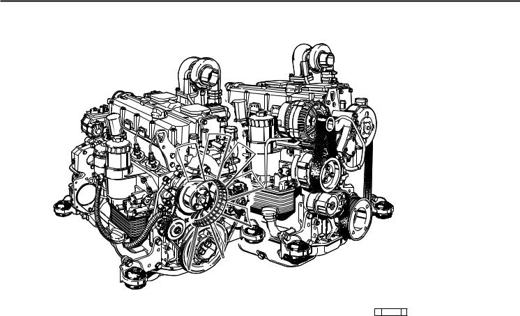
© 31493 0

Общие сведения
|
1 |
||||
|
Двигатели DEUTZ |
Обслуживание и уход |
Сервис |
||
представляют собой результат
многолетних исследований и разработок. Приобретенные при этом опыт и знания в сочетании с высочайшими требованиями к качеству гарантируют изготовление двигателей с продолжительным сроком
службы, исключительной надежностью и
умереннымрасходомтоплива. Самособой разумеется, что выполняются все строгие требованияпоохранеокружающейсреды.
имеютрешающеезначениедлятого, чтобы двигатель полностью отвечал поставленнымтребованиям. Поэтомуисключительно важнособлюдатьустановленнуюпериодичность обслуживания и тщательно выполнятьвсеработыпообслуживаниюиуходу. В особенности нужно следить за такими отклонениями от нормальных условий работы, которыеусложняютэксплуатацию.
Осторожно при работающем двигателе!
Работы по обслуживанию и ремонту должны выполнятьсятольконавыкл.двигателе.Следует убедиться, чтодвигательнельзязапуститьбез
присмотра – опасность несчастного случая! Снятые во время обслуживания защитные приспособленияобязательнонужноустановить
на место после окончания работ. При эксплуатации двигателя в закрытых или подземныхпомещенияхнеобходимособлюдать правилаохранытруда. Привыполненииработ
на работающем двигателе следует надевать прилегающую рабочую одежду. Заправлять топливо разрешается только при выкл. двигателе.
Безопасность
Этот знак сопровождает все указания по технике
!безопасности, несоблюдение
может привести к возникновению прямой
угрозы здоровью и жизни
обслуживающего персонала. Строго соблюдайте эти указания. Обязательно проинструктируйте по технике безопасности весь обслуживающий
персонал. Кромеэтогоследуетсоблюдать законодательные предписания „Общих правил техники безопасности и предупреждения несчастных случаев“.
По вопросам устранения неисправностей и приобретения запасных частей обращайтесь в наши сервисные представительства. В случае выхода двигателя из строя наш обученный персонал позаботится о быстром и квалифицированном ремонте с использованием фирменных запасный частей.
Асбест
В деталях двигателей DEUTZ
не содержится асбест.

1
![]()
Описаниедвигателя
2
2.1Модель
2.2Общий вид двигателя
2.3Система смазки
2.4Топливная система
2.5Система жидкостного охлаждения
© 2003
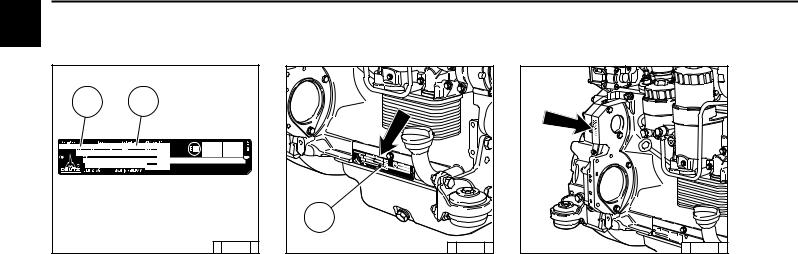
|
Описаниедвигателя |
2.1 Модель |
|||||
|
2 |
2.1.1 |
Фирменнаятабличка |
2.1.2 |
Расположение |
2.1.3 |
Номер двигателя |
|
фирменнойтаблички |
||||||
|
A |
B |
|||||
|
C |
||||||
|
© 26 332 3 |
© 31 488 0 |
© 31 823 0 |
||||
|
Модель A, номер двигателя B, а также |
Фирменная табличка C прикреплена на |
Номер двигателя выбит на картере |
||||
|
техническиеданныевыбитынафирменной |
картере коленвала. |
коленвала (стрелка) и на фирменной |
||||
|
табличке. |
табличке. |
© 2003
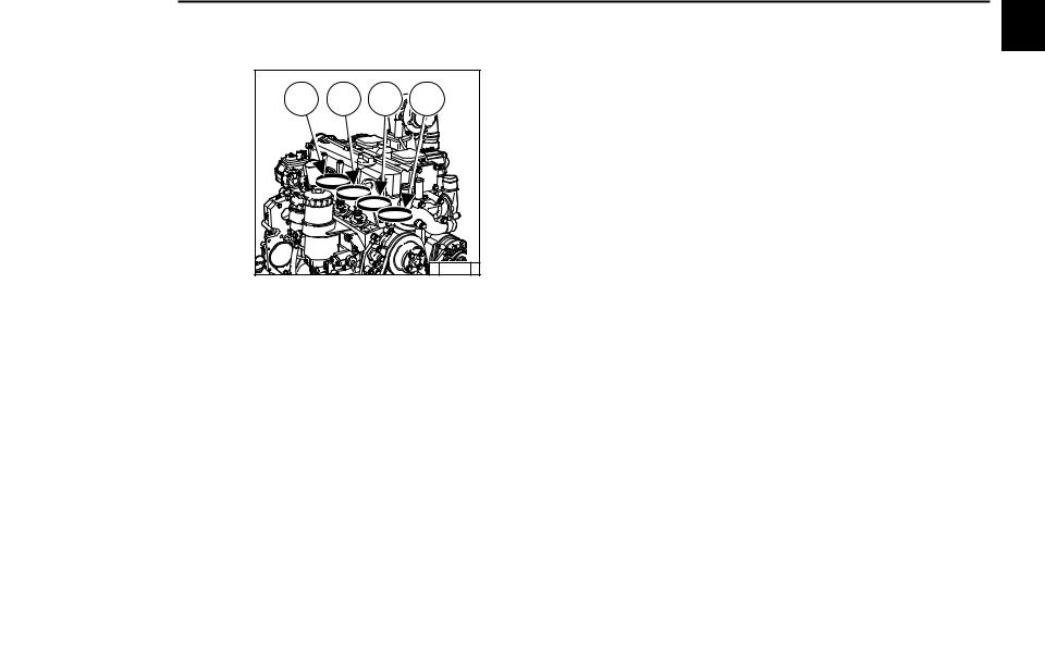
|
2.1 Модель |
Описаниедвигателя |
|||
|
2.1.4 |
Нумерацияцилиндров |
2 |
||
|
1 |
2 |
3 |
4 |
|
|
© 31 813 0 |
||||
|
Цилиндры считаются по порядку, начиная |
||||
|
от маховика. |
© 2003
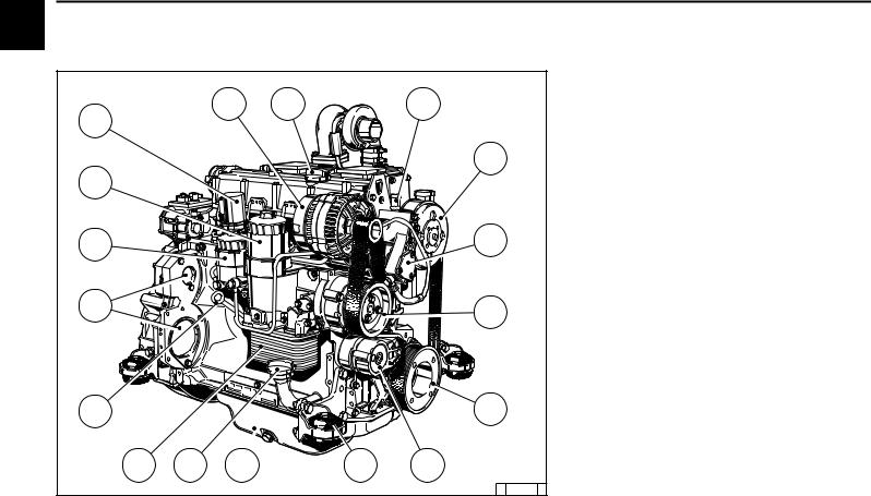
|
Описаниедвигателя |
2.2 Общийвиддвигателя |
|||||||
|
2 |
2.2.1 |
Рабочая сторона 2012 |
||||||
|
Зубчатаяременная передача |
||||||||
|
1 |
Генератор |
|||||||
|
1 |
2 |
3 |
2 |
Заправка масла |
||||
|
17 |
3 |
Штуцер для антифриза — |
||||||
|
4 |
расширительный патрубок |
|||||||
|
Шкив для ремня вентилятора |
||||||||
|
4 |
5 |
Топливный насос |
||||||
|
6 |
Насос охлаждающей жидкости |
|||||||
|
16 |
7 |
Зубчатый шкив на коленчатом валу |
||||||
|
8 |
Натяжной ролик |
|||||||
|
9 |
Опоры |
|||||||
|
10 |
Масляный поддон |
|||||||
|
15 |
5 |
11 |
Маслозаправочная горловина |
|||||
|
12 |
Корпус масляного фильтра с |
|||||||
|
маслорадиатором |
||||||||
|
13 |
Масломер |
|||||||
|
14 |
Установочное место для: |
|||||||
|
14 |
6 |
компрессора или гидравлического |
||||||
|
насоса |
||||||||
|
15 |
Вкладыш топливного фильтра |
|||||||
|
16 |
Вкладыш масляного фильтра |
|||||||
|
17 |
Подъемный электромагнит |
|||||||
|
13 |
7 |
|||||||
|
© 2003 |
12 |
11 |
10 |
9 |
8 |
|||
|
© 31 482 0 |
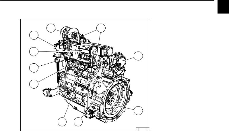
|
2.2 |
Общий вид двигателя |
Описание двигателя |
||
|
2.2.2 |
Сторона стартера 2012 |
2 |
||
|
Зубчатаяременная передача |
||||
|
18 |
Турбонагнетатель |
|||
|
18 |
19 |
19 |
Подвеска двигателя |
|
|
20 |
Регулятор оборотов |
|||
|
27 |
21 |
Маховик |
||
|
22 |
Корпус SAE |
|||
|
23 |
Стартер |
|||
|
24 |
Выхлопной коллектор |
|||
|
25 |
Впускной патрубок охлаждающей |
|||
|
26 |
жидкости |
|||
|
20 |
26 |
Фланец для подогрева не показан |
||
|
27 |
Корпус термостата — Выпускной |
|||
|
патрубок охлаждающей жидкости |
||||
|
25 |
||||
|
24 |
||||
|
21 |
||||
|
23 |
22 |
© 2003 |
||
|
© 31 483 0 |

|
Описание двигателя |
2.2 |
Общий вид двигателя |
|||||
|
2 |
2.2.3 |
Рабочая сторона 2012 |
|||||
|
1 |
Турбонагнетатель |
||||||
|
14 |
1 |
2 |
Фланец для подогрева |
||||
|
3 |
Вентилятор |
||||||
|
4 |
Генератор |
||||||
|
5 |
Клиноременный шкив на коленчатом |
||||||
|
13 |
валу |
||||||
|
6 |
Насос охлаждающей жидкости |
||||||
|
2 |
7 |
Топливный насос |
|||||
|
8 |
Заправка масла |
||||||
|
9 |
Корпус масляного фильтра с |
||||||
|
маслорадиатором |
|||||||
|
12 |
10 |
Корпус масляного фильтра с |
|||||
|
фильтрующим вкладышем |
|||||||
|
3 |
11 |
Масломер |
|||||
|
12 |
Топливный фильтр |
||||||
|
11 |
13 |
Подъемный электромагнит |
|||||
|
14 |
Маслозаправочная горловина |
||||||
|
4 |
|||||||
|
10 |
|||||||
|
2003© |
9 |
||||||
|
8 |
7 |
6 |
© 31 484 0 |
||||
|
5 |
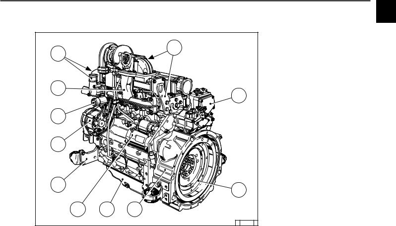
|
2.2 Общийвиддвигателя |
Описаниедвигателя |
||||
|
2.2.4 |
Сторона стартера 2012 |
2 |
|||
|
15 |
Подвеска двигателя |
||||
|
15 |
16 |
Регулятор оборотов |
|||
|
25 |
17 |
Маховик |
|||
|
18 |
Корпус SAE |
||||
|
19 |
Масляный поддон |
||||
|
20 |
Стартер |
||||
|
21 |
Опоры |
||||
|
22 |
Генератор |
||||
|
24 |
23 |
Впускной патрубок охлаждающей |
|||
|
16 |
жидкости |
||||
|
24 |
Выхлопной коллектор |
||||
|
25 |
Выпускной патрубок охлаждающей |
||||
|
23 |
жидкости |
||||
|
22 |
|||||
|
21 |
17 |
||||
|
20 |
19 |
18 |
© 2003 |
||
|
© 31 485 0 |
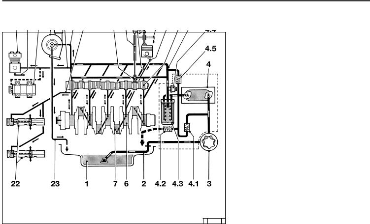
Описание двигателя
© 2003
2.3 Система смазки
1Масляный поддон
2Всасывающий патрубок
3Масляный насос
4Маслорадиатор
4.1Перепускнойклапантеплообменника
4.2Запорный клапан
4.3Сменный масляный фильтр
4.4Датчик давления масла
4.5Регулировочныйклапанмасляного фильтра
5Главный маслопровод
6Коренной подшипник
7Подшипник шатуна
8Подшипник распределительного вала
9Трубка на форсунку
10Форсунка для охлаждения поршня
11Толкатель с импульсной смазкой коромысла
12Шток толкателя, масляный канал для
смазки коромысла
13Коромысло
14Возвратный маслопровод в масляный
поддон
15Маслопровод на турбонагнетатель
16Турбонагнетатель
17Маслопровод на компрессор или гидравлический насос
18Компрессор
19Гидравлический насос
20Возвратный маслопровод с
компрессораилигидравлическогонасоса
21Маслопровод на балансировочный механизм (2x)
22Балансировочные валы
23Турбонагнетатель — возвратный
маслопровод в картер коленвала
© 31 808 1
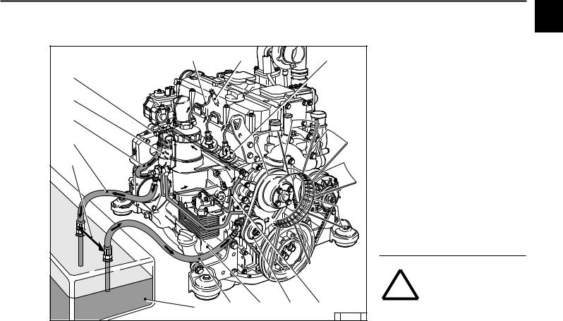
|
2.4 Топливная система |
Описание двигателя |
||||||||||
|
2.4.1 |
Схематопливной системы |
2 |
|||||||||
|
Пример: со стаканным фильтром |
|||||||||||
|
8 |
9 |
7 |
1 |
Топливный бак |
|||||||
|
2 |
Топливопровод на топливный насос |
||||||||||
|
10 |
3 |
Топливный насос |
|||||||||
|
4 |
Топливопровод на топливный фильтр |
||||||||||
|
5 |
Топливный фильтр |
||||||||||
|
5 |
6 |
Топливопровод на насосы высокого |
|||||||||
|
7 |
давления |
||||||||||
|
Топливный насос высокого давления |
|||||||||||
|
11 |
8 |
Топливопровод на клапан впрыска |
|||||||||
|
9 |
Клапан впрыска |
||||||||||
|
12 |
10 |
Полый винт с клапаном регулировки |
|||||||||
|
11 |
давления |
||||||||||
|
Возвратный топливопровод |
|||||||||||
|
13 |
12 |
вытекающего топлива |
|||||||||
|
Возвратный топливопровод в |
|||||||||||
|
13 |
топливный бак |
||||||||||
|
Поддерживать максимально |
|||||||||||
|
возможное расстояние |
|||||||||||
|
При наличии загрязнений в |
|||||||||||
|
топливе |
для |
защиты |
|||||||||
|
! |
двигателей |
настоятельно |
|||||||||
|
рекомендуется установка |
2003 |
||||||||||
|
фильтра предварительной |
|||||||||||
|
1 |
2 |
4 |
3 |
6 |
очистки / ручного |
насоса |
|||||
|
между топливным баком и |
|||||||||||
|
© |
|||||||||||
|
© 31 809 1 |
двигателем. |

|
Описание двигателя |
2.5 |
Система жидкостного охлаждения |
|||||
|
2 |
2.5.1 |
Схема жидкостного охлаждения 2012 |
|||||
|
Пример: со стаканным фильтром |
|||||||
|
1 |
Корпус термостата |
||||||
|
12 |
2 |
Насос охлаждающей жидкости |
|||||
|
3 |
Маслорадиатор |
||||||
|
4 |
Охлаждение цилиндров |
||||||
|
11 |
5 |
Охлаждение головки цилиндров |
|||||
|
13 |
10 |
6 |
Трубкастеплообменниканадвигатель |
||||
|
7 |
Теплообменник |
||||||
|
6 |
8 |
Трубка с двигателя на теплообменник |
|||||
|
9 |
Вентиляционный патрубок из головки |
||||||
|
цилиндров в компенсационный бачок |
|||||||
|
8 |
10 |
Компенсационный бачок |
|||||
|
11 |
Трубкастеплообменниканатермостат |
||||||
|
5 |
12 |
Компенсационный патрубок для |
|||||
|
7 |
охлаждающей жидкости |
||||||
|
13 |
Возвратная трубка охлаждающей |
||||||
|
жидкости с подогрева |
|||||||
|
1 |
14 |
Трубка охлаждающей жидкости на |
|||||
|
подогревсгладкимприводнымремнем |
|||||||
|
2 |
15 |
Трубка охлаждающей жидкости на |
|||||
|
подогрев с зубчатым приводным |
|||||||
|
ремнем |
|||||||
|
15 |
9 |
||||||
|
3 |
|||||||
|
© 2003 |
4 |
14 |
|||||
|
© 31 810 1 |
![]()
Управление
3
3.1Ввод в эксплуатацию
3.2Пуск двигателя
3.3Контроль функционирования
3.4Останов двигателя
3.5Условия эксплуатации
© 2003
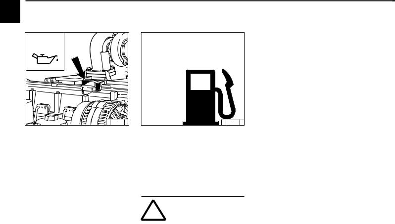
|
Управление |
3.1 Вводвэксплуатацию |
|||||||
|
3 |
3.1.1 |
Заправка моторного |
3.1.2 |
Заправка топлива |
||||
|
масла |
||||||||
|
OIL |
FUEL |
|||||||
|
© 31 491 0 |
© 26 398 0 |
|||||||
|
Как правило, двигатели поставляются не |
Следует применять только очищенное |
|||||||
|
заправленными маслом. |
дизельное топливо общего назначения. |
|||||||
|
Двигатель следует заправить маслом через |
Качество топлива см. в разделе 4.2. |
|||||||
|
заправочную горловину (стрелка). |
Принеобходимостиустановитьтопливный |
|||||||
|
Заправочные объемы см. в разделе 9.1. |
фильтр предварительной очистки. |
|||||||
|
Качествоивязкостьмасласм. вразделе4.1. |
Вслучаесомненийобратитесьвсервисное |
|||||||
|
представительство. |
от |
температуры |
||||||
|
В |
зависимости |
|||||||
|
окружающего воздуха |
необходимо |
|||||||
|
применять летнее или зимнее дизельное |
||||||||
|
топливо. |
||||||||
|
2003 |
! |
Заправлять |
топливо |
|||||
|
разрешается |
только |
при |
||||||
|
выключенном |
двигателе! |
|||||||
|
© |
Следить |
за |
чистотой! |
Не |
||||
|
разливать топливо! |
||||||||

3.1 Вводвэксплуатацию
3.1.3Заправкасистемы охлажденияиудаление воздуха
●2012: согласно указаниям изготовителя системы охлаждения
●Агрегатный двигатель: согласно
указаниям изготовителя системы охлаждения
3.1.4Прочие
подготовительные
работы
●Проверить аккумулятор и кабельные соединения, см. раздел 6.7.1.
●Пробный пуск
— После выполнения подготовительных
работвыполнитьпробныйпусквтечение примерно 10 минут, по возможности без
нагрузки.
Работы во время пробного пуска и после него
— Проверить герметичность уплотнений двигателя.
После остановки двигателя
—Проверить уровень масла, при
необходимостидолить, см. раздел6.1.2.
—Подтянуть приводной ремень, см.
раздел 6.5.
●Обкатка
Во время обкатки, в течение приблизительно 200 часов работы,
рекомендуется проверять уровень масла два раза в день. По окончании
периода обкатки достаточно одной
проверки в день.
●При вводе в эксплуатацию законсервированного двигателя
Выполнить расконсервацию согласно
указаниям в разделе 8.1.
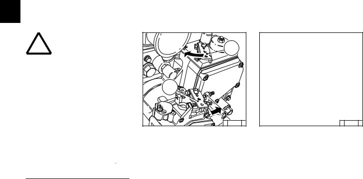
|
Управление |
3.2 Пускдвигателя |
||
|
3 |
|||
|
3.2.1 Электрический пуск |
Безвспомогательногоустройства |
||
пускахолодногодвигателя
Перед пуском двигателя следует убедиться в том, что ! в опасной зоне двигателя или рабочейустановкиникогонет.
После ремонта: Проверить, чтобы были
установлены на место все защитные приспособления, аиздвигателяубранвесь инструмент.
При пуске с помощью фланца для подогрева не применять другие вспомогательные средства пуска (например, впрыск с помощью пускового пилота). Опасность несчастного случая!
Внимание! Категорическизапрещается запускатьдвигательпридемонтированном регуляторе оборотов.
Отсоединить клеммы аккумулятора!
|
2 |
|
|
1 |
|
|
© 31 824 0 |
© 25 745 0 |
|
● По возможности отсоединить двигатель |
● Вставить ключ. |
||
|
от |
приводимого |
устройства |
— Положение 0 = рабочее напряжение |
|
выключением сцепления. |
выключено. |
© 2003
Максимальная продолжительность непрерывного пуска составляет 20 секунд.
Если двигатель не запускается, повторить
попытку пуска черезодну минуту.
Если не удается запустить двигатель после
двух попыток, следует устранить причину неисправности с помощью таблицы поиска
неисправности (раздел 7.1).
●Установить рычаг регулятора оборотов
1 по стрелке в положение средних
оборотов или ниже.
●Рычаг останова 2 перевести в рабочее
положение.
(против стрелки, поз. 1).
●Повернуть ключ вправо.
—Положение 1 = рабочее напряжение
включено
—Загораются сигнальные лампы 1 и 2.
●Прижатьключиповернутьегодалеевправо,
преодолевая сопротивление пружины
—Положение 2 = без функции
—Положение 3 = пуск двигателя.
●Отпустить ключ, как только двигатель
заработает
—Сигнальные лампы погаснут.
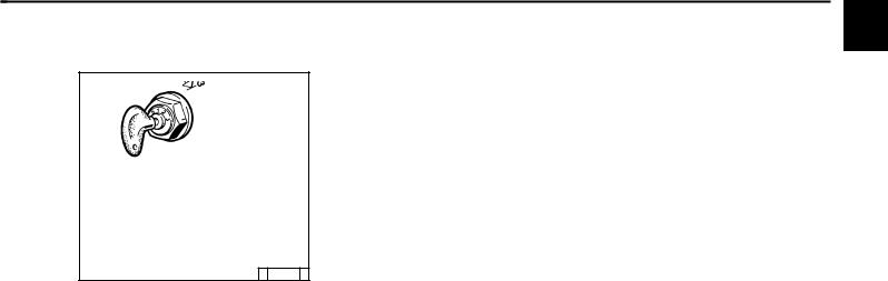
3.2 Пуск двигателя
Совспомогательнымустройством дляпускахолодногодвигателя Фланецдляподогрева
© 25 746 2
●Вставить ключ.
—Положение 0 = рабочее напряжение выключено.
●Повернуть ключ вправо.
—Положение 1 = рабочее напряжение включено.
—Загораются сигнальные лампы. Подогревать, пока не погаснет индикатор подогрева.
●Прижатьключиповернутьегодалеевправо,
преодолевая сопротивление пружиныю
—Положение 2 = без функции
—Положение 3 = пуск двигателя.
●Отпустить ключ, как только двигатель
заработает.
—Сигнальные лампы погаснут.

|
Управление |
3.3 Контроль функционирования |
|||
|
3 |
3.3.1 Давление масла |
|||
|
Сигнальнаялампадавлениямасла |
Указатель давления масла |
Манометр давления масла |
||
|
© |
25 752 |
1 |
© |
25 753 |
0 |
© |
25 754 |
0 |
●Сигнальнаялампадавлениямаслагорит при включенном рабочем напряжении
на выключенном двигателе.
●При работающем двигателе сигнальная
лампа давления масла должна
погаснуть.
|
● Стрелка должна находиться в зеленом |
● Стрелка измерителя давления масла |
|
поле общей рабочей зоны. |
должна показывать минимальное |
|
давление масла (см. раздел 9.1). |
© 2003
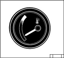
|
3.3 |
Контроль функционирования |
Управление |
||
|
3.3.2 |
Температура |
3 |
||
|
охлаждающей |
||||
|
жидкости |
©26 246 0
●Стрелкауказателятемпературыдолжна постоянно находиться в зеленой зоне и
только изредка переходить в желтозеленую. Перемещение стрелки в
оранжевую зону свидетельствует о
перегреве двигателя.
Остановить двигатель и устранить неисправностьспомощьютаблицы(см.
раздел 7.1).
© 2003
Deutz Engines 912, BF4M2012, F4M2011, BF4M2011, 1011F operators, service and maintenance manuals, error codes list, DTC, spare parts manuals & catalogues, wiring diagrams, schematics free download PDF
![]()
Deutz logo
Deutz engine manuals free download are available for free download.
| Title | File Size | Download Links |
| Deutz 2008-2009 Parts Manual [PDF] | 3.1Mb | Download |
| Deutz 2008-2009 Service Manual [PDF] | 4.4Mb | Download |
| Deutz 226B Operation Manual [PDF] | 8.5Mb | Download |
| Deutz 413 Parts Manual [PDF] | 4.5Mb | Download |
| Deutz Accessories Catalogue [PDF] | 5.2Mb | Download |
| Deutz BF4M1013C Spare Parts Catalogue [PDF] | 3Mb | Download |
| Deutz BFM 1015 Series – BF6M 1015 C, BF8M 1015, BF8M 1015 C, BF8M 1015 CP, BF6M 1015 CP Workshop Manual [PDF] | 12.3Mb | Download |
| Deutz D 2008-2009 Workshop Manual [PDF] | 4.6Mb | Download |
| Deutz D 909 / 910, B / FL 1011 / F / 2011, B / FL 912 / 913 / 914 / C, B / FL 413 F / 513 / C / CP, B / FM 1011 F 2011 Installation Manual [PDF] | 7.8Mb | Download |
| Deutz Engine D2008 2009 Workshop Manual PDF [PDF] | 3.8Mb | Download |
| Deutz Engine Fire Protection – Operation Manual [PDF] | 21.2Mb | Download |
| Deutz Engine S-BV6-8-9M628 Operation Manual [PDF] | 10Mb | Download |
| Deutz FL 411 Service Manual [PDF] | 8.7Mb | Download |
| Deutz FL 413 Service Manual [PDF] | 8.7Mb | Download |
| Deutz Serie 7 Agrotron Service Manual [PDF] | 4.1Mb | Download |
| Gt-50dz Tow Tractor With Deutz Engine [PDF] | 36.1Mb | Download |
Deutz 912
| Title | File Size | Download Links |
| Deutz 912 Parts Manual [PDF] | 4.3Mb | Download |
| Deutz 912 Technical Specifications [PDF] | 384.6kb | Download |
| Deutz 912-913 Repair Manual [PDF] | 5.8Mb | Download |
| Deutz 912-913 Service Manual [PDF] | 2.6Mb | Download |
| Deutz 912-913 Workshop Manual [PDF] | 34.5Mb | Download |
| Deutz F 3 L912 / W, F 4 L912 / W, F 5 L912 / W, B / F6 L912 / W Spare Parts Catalog [PDF] | 15.7Mb | Download |
Deutz 914
| Title | File Size | Download Links |
| Deutz 914 Parts Manual [PDF] | 4.3Mb | Download |
| Deutz 914 Service Manual [PDF] | 2.7Mb | Download |
| Deutz Engine 914 Operation Manual [PDF] | 3.2Mb | Download |
Deutz 1008
| Title | File Size | Download Links |
| Deutz – Workshop Manual BFM 1008F part 1 [PDF] | 2.5Mb | Download |
| Deutz – Workshop Manual BFM 1008F part 2 [PDF] | 2.2Mb | Download |
| Deutz Engines B / FM 1008 / F Workshop Manual [PDF] | 2.7Mb | Download |
Deutz 1011
| Title | File Size | Download Links |
| Deutz 0312 1936 2011 Workshop Manual [PDF] | 20.6Mb | Download |
| Deutz 1011 Parts Manual [PDF] | 1.9Mb | Download |
| Deutz 1011F Workshop Manual [PDF] | 4.7Mb | Download |
| Deutz BF4m1011F Engine Service Parts Manual [PDF] | 4.2Mb | Download |
| Deutz Engine 1011F Werkstatthandbuch [PDF] | 10.3Mb | Download |
| Deutz Engine 1011F Workshop Manual [PDF] | 10.6Mb | Download |
| Deutz Engine B-F L 1011F B-FM 1011F Operation Manual – Engine Description [PDF] | 1.1Mb | Download |
| Deutz Engine B-F L 1011F B-FM 1011F Operation Manual – Engine Operation [PDF] | 157.3kb | Download |
| Deutz Engine B-F L 1011F B-FM 1011F Operation Manual – Engine Preservation [PDF] | 14.2kb | Download |
| Deutz Engine B-F L 1011F B-FM 1011F Operation Manual – Faults, Causes and Remedies [PDF] | 25.1kb | Download |
| Deutz Engine B-F L 1011F B-FM 1011F Operation Manual – General [PDF] | 24.2kb | Download |
| Deutz Engine B-F L 1011F B-FM 1011F Operation Manual – Notes [PDF] | 144.3kb | Download |
| Deutz Engine B-F L 1011F B-FM 1011F Operation Manual – Operating Media [PDF] | 411.2kb | Download |
| Deutz Engine B-F L 1011F B-FM 1011F Operation Manual – Routine Maintenance [PDF] | 299.2kb | Download |
| Deutz Engine B-F L 1011F B-FM 1011F Operation Manual – Service and Maintenance [PDF] | 429.8kb | Download |
| Deutz Engine B-F L 1011F B-FM 1011F Operation Manual – Technical Specifications [PDF] | 53.8kb | Download |
| Deutz Engine B-FL 1011F Operation Manual [PDF] | 2.9Mb | Download |
| Deutz F3M 1011F, BF3M, F4M, BF4M Service Manual [PDF] | 1.3Mb | Download |
Deutz 1012 1013
| Title | File Size | Download Links |
| Deutz 1012 1013 Operation and Maintenance Manual [PDF] | 3.8Mb | Download |
| Deutz 1012-1013 Service Manual [PDF] | 3.6Mb | Download |
| Deutz Engine 1012-1013 Workshop Manual [PDF] | 4.7Mb | Download |
Deutz 1015
| Title | File Size | Download Links |
| Deutz 1015 Maintenance Manual rus [PDF] | 2.8Mb | Download |
| Deutz BFM 1015 Workshop Manual [PDF] | 3.9Mb | Download |
Deutz 2011
| Title | File Size | Download Links |
| Deutz 0312 1936 2011 Workshop Manual- competence level 3 [PDF] | 20.6Mb | Download |
| Deutz 0312 4004 2011 Workshop Manual- competence level 2 [PDF] | 7.5Mb | Download |
| Deutz 2011 – Operation Manual [PDF] | 2.7Mb | Download |
| Deutz D 2011 w, TD 2011 w, TCD 2011 w Workshop Manual- competence level 2 [PDF] | 9.9Mb | Download |
| Deutz D 2011, TD 2011 Workshop Manual- competence level 2 [PDF] | 15.8Mb | Download |
| Deutz Engine B-FL-FM 2011 Operation Manual [PDF] | 7.1Mb | Download |
| Deutz F2M 2011, F3M 2011, F4M 2011, BF3M 2011, BF4M 2011, BF3L 2011, BF4L 2011 F2L 2011, F3L 2011, F4L 2011 Operation Manual [PDF] | 5.2Mb | Download |
| Deutz F4M 2011 Technical Specifications [PDF] | 278.7kb | Download |
| Deutz F4M2011 Service Manual pdf [PDF] | 5.2Mb | Download |
Deutz 2012
| Title | File Size | Download Links |
| Deutz 2012 Service Manual [PDF] | 9.5Mb | Download |
| Deutz BF4M 2012 Operation Manual [PDF] | 4.6Mb | Download |
| Deutz BF4M2012 Workshop Manual [PDF] | 14.3Mb | Download |
| Deutz Engine 2012 Operation Manual [PDF] | 3.7Mb | Download |
| Deutz Engine BF6M 1013 Operation Manual [PDF] | 3.3Mb | Download |
| Deutz Engine BFM-2012 Workshop Manual [PDF] | 8.7Mb | Download |
Deutz TCD 2012
| Title | File Size | Download Links |
| Deutz TCD 2012-2013 Service Manual [PDF] | 3.9Mb | Download |
| Deutz TCD2012 Instruction Manual [PDF] | 5.1Mb | Download |
Deutz TCD 2013
| Title | File Size | Download Links |
| Deutz Engine TCD 2013 2V Workshop Manual [PDF] | 26.9Mb | Download |
| Deutz Engine TCD 2013 L04-06 4V Instruction Manual – Care and maintenance work [PDF] | 1017.5kb | Download |
| Engine corrosion protection [PDF] | 119kb | Download |
| Engine Description [PDF] | 2.1Mb | Download |
| Faults, causes, and remedies [PDF] | 79.7kb | Download |
| General [PDF] | 13.1kb | Download |
| Maintenance [PDF] | 493.5kb | Download |
| Operating substances [PDF] | 44.7kb | Download |
| Operation Manual [PDF] | 15.6kb | Download |
| Operation [PDF] | 151.7kb | Download |
| Service [PDF] | 22.5kb | Download |
| Technical data [PDF] | 72.2kb | Download |
| Deutz TCD 2013 4V – Industry Workshop Manual [PDF] | 535.7kb | Download |
Deutz Engine TCD 2015 Service Manual
| Title | File Size | Download Links |
| General [PDF] | 18.1kb | Download |
| Job card overview [PDF] | 20.3Mb | Download |
| Special tools [PDF] | 299.3kb | Download |
| Standard tools [PDF] | 93.2kb | Download |
| Technical data [PDF] | 185.4kb | Download |
| User notes [PDF] | 51.8kb | Download |
| Deutz TCD 2015 Service Manual [PDF] | 3.2Mb | Download |
Deutz Engines
Modern technologies and materials, top quality, dependability, durability, and longevity are all features of Deutz diesel engines manufactured in Germany. German brand engines have high specific power and torque at the lightest possible weight for power plants with such specs. As a result, Deutz engines, which use the company’s unique innovations, can function well even in the most adverse circumstances and at a high maximum load for extended periods without diminishing motor resources or increasing overhaul time, therefore saving operational expenses.
After years of research at the company’s scientific and design bureaus, Deutz engineers developed motors that balance low operating costs and little impact on the environment. Because of their low fuel consumption, power plants from the German company Deutz are among the most cost effective in the world per kilowatt-hour produced, and they conform to the strictest standards for environmental protection. This means you may save money on gasoline and put Deutz generator installations close to where people live and work.
The Deutz 413 Series consists of V-shaped (V-Twin) diesel engines with 6, 8, 10, or 12 cylinders, a horizontal selection shaft, and valves in the upper location (OHV) for use in industrial and domestic applications. Focused on usage in sub-zero temperatures (down to -30 degrees Celsius), the 137 hp. (100 kW) to 322 hp. (236 kW) range of power and forced air conditioning;
Four-stroke, overhead-valve (OHV), horizontal power-shaft (HPS), and forced-air-cooled (FAC.) Deutz 912 Series diesel engines are designed for typical circumstances and may produce anywhere from 47 horsepower (34 kilowatts) to 111 horsepower (70 kW) (82 kW). The W models have a two-stage fuel combustion mechanism;
The Deutz 913 Series consists of 4-stroke, 3, 4, and 6-cylinder diesel engines with OHV, a horizontal power shaft, and forced air cooling, designed for use in typical circumstances and ranging in output from 59 horsepower (44 kilowatts) to 191 horsepower (141 kilowatts);
The Deutz 914 Series consists of four-stroke, three-, four-, five-, and six-cylinder diesel engines designed for professional and household appliances, featuring overhead valves, a horizontal power shaft, and forced air cooling, and optimized for normal conditions of operation between 59 horsepower (44 kilowatts) and 189 horsepower (141 kilowatts);
The Deutz 912/914 Genset Series includes 19 hp (14 kW) to 97.9 hp (4-stroke, 2, 3, 4, 6, 6-cylinder, OHV, horizontal air-cooled shaft, air-cooled) diesel engines for electro generators designed for usage in normal and harsh climatic situations (73 kW) manufactured with a mechanical or electronic (optional) fuel supply regulator;
The Deutz 1008 Series is a line of four-stroke, 2, 3, and 4-cylinder diesel engines designed for use in construction machinery, featuring overhead valves (OHV), a horizontal power shaft, liquid cooling, and an emphasis on operating in harsh environments, with outputs ranging from 17.7 horsepower (13 kilowatts) to 42 horsepower (31 kilowatts).
The Deutz 1011 Series is a line of 30-liter, 4-stroke, 2-, 3-, and 4-cylinder diesel engines used in construction machinery. These engines have overhead valves (OHV), a horizontal power shaft, and liquid cooling and are optimized for usage in harsh climates. (22 kW) up to (89.5 hp) (61 kW). Gas emission regulations that are in line with those of the European Union’s STEP II and the United States CFR 40, part 89, Tier II;
The Deutz 1013 Series consists of 4-stroke, 4- and 6-cylinder diesel engines with OHV, the horizontal power shaft, liquid cooling, and an output range of 154 hp (115 kW) to 313 hp (233 kW) for use in industrial and construction equipment in both mild and severe climates.
The Deutz 1015 Series consists of 6- and 8-cylinder V-shaped diesel engines with OHV, a horizontal power shaft, liquid cooling, and an output range of 407 hp (300 kW) to 598 hp (440 kW) that are designed for usage in typical climates.
The Deutz 1013/1015 Genset Series consists of four-stroke, six- and eight-cylinder diesel engines for electric generators, with overhead valves (OHV), a horizontal power shaft, liquid cooling, and an output ranging from 103 horsepower (77 kilowatts) to 571 horsepower (362 kilowatts) (426 kW) produced using both a mechanical regulator and electronic control (as an extra);
With power ranging from 31 horsepower (23 kilowatts) to 88 horsepower (65 kilowatts), the Deutz 2011 Series consists of 2, 3, 4, and 4-cylinder diesel engines for mobile medium-power mobile equipment with OHV, horizontal power shaft, air or liquid cooling, and an emphasis on operation in normal climatic conditions; the L models feature a heat exchanger.
The Deutz TCD 2011 Series is a line of air-cooled, OHV, horizontally-mounted, 2- and 3-cylinder diesel engines for medium-power mobile equipment ranging in output from 31 to 100 horsepower (23 to 74 kilowatts) (74.9 kW). Meet the gas emission requirements of European Union (EU) STEP III and United States (US) Tier 3;

Deutz f4m2011
The Deutz 2012 Series is a line of four- and six-cylinder diesel engines designed for medium-power mobile equipment. They feature overhead valves (OHV), a horizontal power shaft, and liquid cooling and are optimized for use in typical climates. Their output ranges from 101.8 horsepower (74.9 kilowatts) to 210 horsepower (155 kilowatts).
The Deutz TCD 2012 Series is a four-stroke and six-cylinder diesel engine line designed for medium-power mobile equipment. They feature overhead valves (OHV), a horizontal power shaft, and liquid cooling and are optimized for use in temperate climates.
The Deutz 2011/2012 Genset Series consists of four-stroke 2, 3, and 4-cylinder diesel engines for electric generators with overhead valves, horizontal power shafts, liquid or air cooling, and a primary focus on operation in both normal and difficult climatic conditions, with outputs ranging from 15.5 horsepower (11.4 kilowatts) to 101 horsepower (75 kilowatts);
The Deutz TCD2013 Series is a line of four- and six-cylinder diesel engines designed for use in mobile medium-power equipment. These engines feature overhead valves (OHV), a horizontal power shaft, liquid cooling, and are optimized for use in temperate climates. Their output ranges from 173 horsepower (129 kilowatts) to 325.9 horsepower (243 kW). Meet the requirements for gas emissions set out by the European Union’s STEP III A and the United States’ Tier 3;
The Deutz TCD2013 Genset Series consists of four- and six-cylinder diesel engines with an output ranging from 121 horsepower (90 kilowatts) to 314 horsepower (234 kilowatts) with an emphasis on normal climate operating.
The Deutz TCD 2015 Series consists of 6 and 8-cylinder, OHV, the horizontal power shaft, liquid-cooled, industrial diesel engines designed for usage in typical climates and capable of producing between 489 horsepower (360 kilowatts) and 670 horsepower (500 kilowatts);
The Deutz TCD 2.9-16 liter Series consists of 4, 6, and 8-cylinder diesel engines for mobile equipment; their engine volumes range from 2.9 to 16 liters; they feature overhead valves (OHV), a horizontal power shaft, water cooling, and are optimized for use in extreme climates; their outputs range from 50 horsepower (36.9 kW) to 697 horsepower (600 lb-ft) (520 kW).
![]()
Руководство по эксплуатации
2012
© 2003
© 2003
●Внимательно прочитайте это руководствопоэксплуатацииистрогособлюдайте
содержащиеся в нем указания. Таким
образомВыизбежитенесчастныхслучаев, сохраните гарантию изготовителя и
получите в свое распоряжение полно-
функциональный двигатель, постоянно готовый к работе.
●Двигатель предназначен для работы исключительнопоназначению,определен-
ному в документации на комплект постав-
ки, и имеет соответствующую конструкцию, разработанную изготовителем
оборудования (использование по
назначению). Любое другое применение рассматривается как использование не
по назначению. Изготовитель не несет
ответственности за возникший по этой причине ущерб. Весь риск при этом
полностью возлагается на пользователя.
●Киспользованиюпоназначениюотносится
также соблюдение правил эксплуатации,
обслуживания и ремонта, установленных изготовителем. К эксплуатации, обслужи-
ванию и ремонту двигателя допускается
только изучивший настоящее руководство и проинструктированный по технике безопасности персонал.
●Следует также соблюдать соответствующие правила предотвращения не-
счастныхслучаевипрочиеобщепринятые
правила техники безопасности и производственной гигиены.
●На работающем двигателе могут представлять опасность травмирования:
— вращающиеся и горячие детали;
На двигателях с принудительным зажиганием:
— системазажигания(высокоеэлектрическое
напряжение). Избегайте прикосновения!
●Самовольное внесение изменений в конструкцию двигателя исключает
ответственность изготовителя за
понесенный в результате этого ущерб. Кроме того, вмешательство в системы
подачи топлива и регулирования может
понизитьмощностьдвигателяиухудшить состав выхлопных газов. При этом не
будет обеспечиваться соблюдение
законодательных норм по охране окружающей среды.
●Не допускается изменять, загораживать или закрывать приток охлажда-
ющего воздуха к вентилятору.
Изготовитель не несет ответственности за возникшие в результате
этого повреждения.
●При выполнении работ по обслужи-
ванию и ремонту двигателя следует
применять только фирменные запасные части DEUTZ. Они изготовлены
специально для Вашего двигателя и
обеспечивают его безотказную работу. При несоблюдении этого условия
гарантия аннулируется.
●Работы по обслуживанию и очистке можно выполнять только на выклю-
ченном и охлажденном двигателе. При
этом следует следить за тем, чтобы было отключено электрооборудование
и вынут ключ зажигания.
Следует соблюдать правила предупреждения несчастных случаев при
работе на электроустановках (напри-
мер, стандарт -VDE-0100/-0101/-0104/- 0105, „Меры предосторожности при
работе с токоведущими частями,
находящимися под опасным напряжением“).
На время очистки с применением
жидкостей необходимо плотно закрыть
все части электрооборудования.
Номер двигателя:
Впишитездесьномердвигателя. Этооблегчит
решениевопросовприобращениивсервисную службу по поводу обслуживания, ремонта и
заказа запасных частей (см. раздел 2.1).
Приведенные в этом руководстве по
эксплуатации иллюстрации и данные могут отличаться от реального оборудования из-за
технических усовершенствований двигателя.
Полная или частичная перепечатка и размножениевлюбойформевозможнытолько
с письменного разрешения изготовителя.
Руководство по
эксплуатации
2012
0312 1370 ru
© 2003
Предисловие
Уважаемыйзаказчик!
Двигатели с жидкостным охлаждением
маркиDEUTZ предназначеныдляширокого
кругаприменения. Приэтомбогатыйвыбор предлагаемых вариантов обеспечивает
выполнение самых разнообразных
требований заказчика.
Вашдвигательоборудованвсоответствии
сегоконкретнымназначением, поэтомуна нем установлены не все узлы и детали,
описанные в настоящем руководстве по
эксплуатации.
Мыстаралисьясновыделитьэтиразличия,
чтобы облегчить поиск указаний по эксплуатации и обслуживанию для конкретного варианта оборудования.
Обязательно прочитайте эти указания
передтем, какприступитьквводудвигателя в эксплуатацию, и соблюдайте их при его эксплуатации и обслуживании.
Мы всегда готовы помочь Вам по любому вопросу.
Ваша
Компания DEUTZ AG
Содержание
|
1. |
Общиесведения |
3.2.1 |
Электрический пуск |
6. Работы по уходу и |
|
|
2. |
Описаниедвигателя |
3.3 |
Контроль функционирования |
обслуживанию |
|
|
3.3.1 |
Давление масла |
6.1 |
Система смазки |
||
|
2.1 |
Модель |
3.3.2 |
Температураохлаждающейжидкости |
6.1.1 |
Интервалы замены масла |
|
2.1.1 |
Фирменная табличка |
3.4 |
Останов двигателя |
6.1.2 |
Проверка уровня масла, замена |
|
2.1.2 |
Расположение фирменной |
3.4.1 |
Механический останов |
моторного масла |
|
|
таблички |
3.4.2 |
Электрический останов |
6.1.3 |
Замена масляного фильтра |
|
|
2.1.3 |
Номер двигателя |
3.5 |
Условия эксплуатации |
6.1.4 Очистка / замена масляного |
|
|
2.1.4 |
Нумерация цилиндров |
3.5.1 |
Зимняя эксплуатация |
фильтра (стакана) |
|
|
2.2 |
Общий вид двигателя |
3.5.2 |
Повышенная температура |
6.2 |
Топливная система |
|
2.2.1 |
Рабочая сторона 2012 |
окружающей среды, высокогорье |
6.2.1 |
Замена топливного фильтра |
|
|
Зубчатая ременная передача |
4. |
Горюче-смазочные |
6.2.2 Очистка / замена топливного |
||
|
2.2.2 |
Сторона стартера 2012 |
фильтра (стакана) |
|||
|
Зубчатая ременная передача |
материалы |
6.2.3 |
Топливныйфильтрпредварительной |
||
|
2.2.3 |
Рабочая сторона 2012 |
4.1 |
Моторное масло |
очистки,очистка и замена фильтру- |
|
|
2.2.4 |
Сторона стартера 2012 |
4.1.1 |
Качество |
ющего вкладыша-удаление воды |
|
|
2.3 |
Система смазки |
4.1.2 |
Вязкость |
6.2.4 Удаление воздуха из топливной |
|
|
2.3.1 |
Схема смазки |
4.2 |
Топливо |
системы с топливным фильтром |
|
|
2.4 |
Топливная система |
4.2.1 |
Качество |
предварительной очистки |
|
|
2.4.1 |
Схема топливной системы |
4.2.2 |
Зимнее топливо |
6.2.5 Удаление воздуха из топливной |
|
|
2.5 |
Система жидкостного охлаждения |
4.3 |
Охлаждающая жидкость |
системы без топливного фильтра |
|
|
2.5.1 |
Схемажидкостногоохлаждения2012 |
4.3.1 |
Качество воды для охлаждающей |
предварительной очистки |
|
|
3. |
Управление |
жидкости |
6.3 |
Система охлаждения |
|
|
4.3.2 |
Приготовление охлаждающей |
6.3.1 |
Интервалы очистки |
||
|
3.1 |
Ввод в эксплуатацию |
жидкости |
6.3.2 |
Очистка системы охлаждения |
|
|
3.1.1 |
Заправка моторного масла |
4.3.3 |
Средство защиты системы |
6.3.3 |
Сливание системы охлаждения |
|
3.1.2 |
Заправка топлива |
охлаждения |
6.3.4 Заправка системы охлаждения и |
||
|
3.1.3 Заправка системы охлаждения и |
5. |
Техническое |
удаление воздуха 2012 |
||
|
удаление воздуха |
6.4 Воздушный фильтр для камеры |
||||
|
3.1.4 |
Прочие подготовительные работы |
обслуживание |
сгорания |
||
|
3.2 |
Пуск двигателя |
5.1 |
График техобслуживания |
6.4.1 |
Интервалы очистки |
|
5.2 |
Схема техобслуживания |
6.4.2 |
Сливание циклонного сепаратора |
||
|
5.3 |
Выполненные работы по |
грубой очистки |
|||
|
техобслуживанию |
6.4.3 |
Сухой воздушный фильтр |
Содержание
6.5Ременная передача
6.5.1Проверка приводного ремня
—2012 стандартный
—2012 с зубчатым ремнем
6.5.2Натяжение приводного ремня
Насос охлаждающей жидкости / топливный насос
6.5.3Замена приводного ремня Насос охлаждающей жидкости /
топливный насос
6.5.4Приводной ремень Замена зубчатого приводного
ремня
6.5.5Натяжение приводного ремня Генератор
6.5.6Замена приводного ремня Генератор
6.5.7Зубчатый приводной ремень,
пределы износа, проверка
6.6Регулировочные работы
6.6.1Проверказазораклапанов, при
необходимости– регулировка
6.7Вспомогательные узлы
6.7.1Аккумулятор
6.7.2Генератор переменного тока
6.7.3Транспортная подвеска
7.Неисправности, их причины и устранение
8.Консервациядвигателя
8.1Консервация
9.Технические данные
9.1Характеристики двигателя и
регулировочные данные
9.2Моменты затяжки резьбовых соединений
9.3Инструмент
10. Сервис
7.1Таблица неисправностей
© 31493 0
Общие сведения
|
1 |
||||
|
Двигатели DEUTZ |
Обслуживание и уход |
Сервис |
||
представляют собой результат
многолетних исследований и разработок. Приобретенные при этом опыт и знания в сочетании с высочайшими требованиями к качеству гарантируют изготовление двигателей с продолжительным сроком
службы, исключительной надежностью и
умереннымрасходомтоплива. Самособой разумеется, что выполняются все строгие требованияпоохранеокружающейсреды.
имеютрешающеезначениедлятого, чтобы двигатель полностью отвечал поставленнымтребованиям. Поэтомуисключительно важнособлюдатьустановленнуюпериодичность обслуживания и тщательно выполнятьвсеработыпообслуживаниюиуходу. В особенности нужно следить за такими отклонениями от нормальных условий работы, которыеусложняютэксплуатацию.
Осторожно при работающем двигателе!
Работы по обслуживанию и ремонту должны выполнятьсятольконавыкл.двигателе.Следует убедиться, чтодвигательнельзязапуститьбез
присмотра – опасность несчастного случая! Снятые во время обслуживания защитные приспособленияобязательнонужноустановить
на место после окончания работ. При эксплуатации двигателя в закрытых или подземныхпомещенияхнеобходимособлюдать правилаохранытруда. Привыполненииработ
на работающем двигателе следует надевать прилегающую рабочую одежду. Заправлять топливо разрешается только при выкл. двигателе.
Безопасность
Этот знак сопровождает все указания по технике
!безопасности, несоблюдение
может привести к возникновению прямой
угрозы здоровью и жизни
обслуживающего персонала. Строго соблюдайте эти указания. Обязательно проинструктируйте по технике безопасности весь обслуживающий
персонал. Кромеэтогоследуетсоблюдать законодательные предписания „Общих правил техники безопасности и предупреждения несчастных случаев“.
По вопросам устранения неисправностей и приобретения запасных частей обращайтесь в наши сервисные представительства. В случае выхода двигателя из строя наш обученный персонал позаботится о быстром и квалифицированном ремонте с использованием фирменных запасный частей.
Асбест
В деталях двигателей DEUTZ
не содержится асбест.
1
![]()
Описаниедвигателя
2
2.1Модель
2.2Общий вид двигателя
2.3Система смазки
2.4Топливная система
2.5Система жидкостного охлаждения
© 2003
|
Описаниедвигателя |
2.1 Модель |
|||||
|
2 |
2.1.1 |
Фирменнаятабличка |
2.1.2 |
Расположение |
2.1.3 |
Номер двигателя |
|
фирменнойтаблички |
||||||
|
A |
B |
|||||
|
C |
||||||
|
© 26 332 3 |
© 31 488 0 |
© 31 823 0 |
||||
|
Модель A, номер двигателя B, а также |
Фирменная табличка C прикреплена на |
Номер двигателя выбит на картере |
||||
|
техническиеданныевыбитынафирменной |
картере коленвала. |
коленвала (стрелка) и на фирменной |
||||
|
табличке. |
табличке. |
© 2003
|
2.1 Модель |
Описаниедвигателя |
|||
|
2.1.4 |
Нумерацияцилиндров |
2 |
||
|
1 |
2 |
3 |
4 |
|
|
© 31 813 0 |
||||
|
Цилиндры считаются по порядку, начиная |
||||
|
от маховика. |
© 2003
|
Описаниедвигателя |
2.2 Общийвиддвигателя |
|||||||
|
2 |
2.2.1 |
Рабочая сторона 2012 |
||||||
|
Зубчатаяременная передача |
||||||||
|
1 |
Генератор |
|||||||
|
1 |
2 |
3 |
2 |
Заправка масла |
||||
|
17 |
3 |
Штуцер для антифриза — |
||||||
|
4 |
расширительный патрубок |
|||||||
|
Шкив для ремня вентилятора |
||||||||
|
4 |
5 |
Топливный насос |
||||||
|
6 |
Насос охлаждающей жидкости |
|||||||
|
16 |
7 |
Зубчатый шкив на коленчатом валу |
||||||
|
8 |
Натяжной ролик |
|||||||
|
9 |
Опоры |
|||||||
|
10 |
Масляный поддон |
|||||||
|
15 |
5 |
11 |
Маслозаправочная горловина |
|||||
|
12 |
Корпус масляного фильтра с |
|||||||
|
маслорадиатором |
||||||||
|
13 |
Масломер |
|||||||
|
14 |
Установочное место для: |
|||||||
|
14 |
6 |
компрессора или гидравлического |
||||||
|
насоса |
||||||||
|
15 |
Вкладыш топливного фильтра |
|||||||
|
16 |
Вкладыш масляного фильтра |
|||||||
|
17 |
Подъемный электромагнит |
|||||||
|
13 |
7 |
|||||||
|
© 2003 |
12 |
11 |
10 |
9 |
8 |
|||
|
© 31 482 0 |
|
2.2 |
Общий вид двигателя |
Описание двигателя |
||
|
2.2.2 |
Сторона стартера 2012 |
2 |
||
|
Зубчатаяременная передача |
||||
|
18 |
Турбонагнетатель |
|||
|
18 |
19 |
19 |
Подвеска двигателя |
|
|
20 |
Регулятор оборотов |
|||
|
27 |
21 |
Маховик |
||
|
22 |
Корпус SAE |
|||
|
23 |
Стартер |
|||
|
24 |
Выхлопной коллектор |
|||
|
25 |
Впускной патрубок охлаждающей |
|||
|
26 |
жидкости |
|||
|
20 |
26 |
Фланец для подогрева не показан |
||
|
27 |
Корпус термостата — Выпускной |
|||
|
патрубок охлаждающей жидкости |
||||
|
25 |
||||
|
24 |
||||
|
21 |
||||
|
23 |
22 |
© 2003 |
||
|
© 31 483 0 |
|
Описание двигателя |
2.2 |
Общий вид двигателя |
|||||
|
2 |
2.2.3 |
Рабочая сторона 2012 |
|||||
|
1 |
Турбонагнетатель |
||||||
|
14 |
1 |
2 |
Фланец для подогрева |
||||
|
3 |
Вентилятор |
||||||
|
4 |
Генератор |
||||||
|
5 |
Клиноременный шкив на коленчатом |
||||||
|
13 |
валу |
||||||
|
6 |
Насос охлаждающей жидкости |
||||||
|
2 |
7 |
Топливный насос |
|||||
|
8 |
Заправка масла |
||||||
|
9 |
Корпус масляного фильтра с |
||||||
|
маслорадиатором |
|||||||
|
12 |
10 |
Корпус масляного фильтра с |
|||||
|
фильтрующим вкладышем |
|||||||
|
3 |
11 |
Масломер |
|||||
|
12 |
Топливный фильтр |
||||||
|
11 |
13 |
Подъемный электромагнит |
|||||
|
14 |
Маслозаправочная горловина |
||||||
|
4 |
|||||||
|
10 |
|||||||
|
2003© |
9 |
||||||
|
8 |
7 |
6 |
© 31 484 0 |
||||
|
5 |
|
2.2 Общийвиддвигателя |
Описаниедвигателя |
||||
|
2.2.4 |
Сторона стартера 2012 |
2 |
|||
|
15 |
Подвеска двигателя |
||||
|
15 |
16 |
Регулятор оборотов |
|||
|
25 |
17 |
Маховик |
|||
|
18 |
Корпус SAE |
||||
|
19 |
Масляный поддон |
||||
|
20 |
Стартер |
||||
|
21 |
Опоры |
||||
|
22 |
Генератор |
||||
|
24 |
23 |
Впускной патрубок охлаждающей |
|||
|
16 |
жидкости |
||||
|
24 |
Выхлопной коллектор |
||||
|
25 |
Выпускной патрубок охлаждающей |
||||
|
23 |
жидкости |
||||
|
22 |
|||||
|
21 |
17 |
||||
|
20 |
19 |
18 |
© 2003 |
||
|
© 31 485 0 |
Описание двигателя
© 2003
2.3 Система смазки
1Масляный поддон
2Всасывающий патрубок
3Масляный насос
4Маслорадиатор
4.1Перепускнойклапантеплообменника
4.2Запорный клапан
4.3Сменный масляный фильтр
4.4Датчик давления масла
4.5Регулировочныйклапанмасляного фильтра
5Главный маслопровод
6Коренной подшипник
7Подшипник шатуна
8Подшипник распределительного вала
9Трубка на форсунку
10Форсунка для охлаждения поршня
11Толкатель с импульсной смазкой коромысла
12Шток толкателя, масляный канал для
смазки коромысла
13Коромысло
14Возвратный маслопровод в масляный
поддон
15Маслопровод на турбонагнетатель
16Турбонагнетатель
17Маслопровод на компрессор или гидравлический насос
18Компрессор
19Гидравлический насос
20Возвратный маслопровод с
компрессораилигидравлическогонасоса
21Маслопровод на балансировочный механизм (2x)
22Балансировочные валы
23Турбонагнетатель — возвратный
маслопровод в картер коленвала
© 31 808 1
|
2.4 Топливная система |
Описание двигателя |
||||||||||
|
2.4.1 |
Схематопливной системы |
2 |
|||||||||
|
Пример: со стаканным фильтром |
|||||||||||
|
8 |
9 |
7 |
1 |
Топливный бак |
|||||||
|
2 |
Топливопровод на топливный насос |
||||||||||
|
10 |
3 |
Топливный насос |
|||||||||
|
4 |
Топливопровод на топливный фильтр |
||||||||||
|
5 |
Топливный фильтр |
||||||||||
|
5 |
6 |
Топливопровод на насосы высокого |
|||||||||
|
7 |
давления |
||||||||||
|
Топливный насос высокого давления |
|||||||||||
|
11 |
8 |
Топливопровод на клапан впрыска |
|||||||||
|
9 |
Клапан впрыска |
||||||||||
|
12 |
10 |
Полый винт с клапаном регулировки |
|||||||||
|
11 |
давления |
||||||||||
|
Возвратный топливопровод |
|||||||||||
|
13 |
12 |
вытекающего топлива |
|||||||||
|
Возвратный топливопровод в |
|||||||||||
|
13 |
топливный бак |
||||||||||
|
Поддерживать максимально |
|||||||||||
|
возможное расстояние |
|||||||||||
|
При наличии загрязнений в |
|||||||||||
|
топливе |
для |
защиты |
|||||||||
|
! |
двигателей |
настоятельно |
|||||||||
|
рекомендуется установка |
2003 |
||||||||||
|
фильтра предварительной |
|||||||||||
|
1 |
2 |
4 |
3 |
6 |
очистки / ручного |
насоса |
|||||
|
между топливным баком и |
|||||||||||
|
© |
|||||||||||
|
© 31 809 1 |
двигателем. |
|
Описание двигателя |
2.5 |
Система жидкостного охлаждения |
|||||
|
2 |
2.5.1 |
Схема жидкостного охлаждения 2012 |
|||||
|
Пример: со стаканным фильтром |
|||||||
|
1 |
Корпус термостата |
||||||
|
12 |
2 |
Насос охлаждающей жидкости |
|||||
|
3 |
Маслорадиатор |
||||||
|
4 |
Охлаждение цилиндров |
||||||
|
11 |
5 |
Охлаждение головки цилиндров |
|||||
|
13 |
10 |
6 |
Трубкастеплообменниканадвигатель |
||||
|
7 |
Теплообменник |
||||||
|
6 |
8 |
Трубка с двигателя на теплообменник |
|||||
|
9 |
Вентиляционный патрубок из головки |
||||||
|
цилиндров в компенсационный бачок |
|||||||
|
8 |
10 |
Компенсационный бачок |
|||||
|
11 |
Трубкастеплообменниканатермостат |
||||||
|
5 |
12 |
Компенсационный патрубок для |
|||||
|
7 |
охлаждающей жидкости |
||||||
|
13 |
Возвратная трубка охлаждающей |
||||||
|
жидкости с подогрева |
|||||||
|
1 |
14 |
Трубка охлаждающей жидкости на |
|||||
|
подогревсгладкимприводнымремнем |
|||||||
|
2 |
15 |
Трубка охлаждающей жидкости на |
|||||
|
подогрев с зубчатым приводным |
|||||||
|
ремнем |
|||||||
|
15 |
9 |
||||||
|
3 |
|||||||
|
© 2003 |
4 |
14 |
|||||
|
© 31 810 1 |
![]()
Управление
3
3.1Ввод в эксплуатацию
3.2Пуск двигателя
3.3Контроль функционирования
3.4Останов двигателя
3.5Условия эксплуатации
© 2003
|
Управление |
3.1 Вводвэксплуатацию |
|||||||
|
3 |
3.1.1 |
Заправка моторного |
3.1.2 |
Заправка топлива |
||||
|
масла |
||||||||
|
OIL |
FUEL |
|||||||
|
© 31 491 0 |
© 26 398 0 |
|||||||
|
Как правило, двигатели поставляются не |
Следует применять только очищенное |
|||||||
|
заправленными маслом. |
дизельное топливо общего назначения. |
|||||||
|
Двигатель следует заправить маслом через |
Качество топлива см. в разделе 4.2. |
|||||||
|
заправочную горловину (стрелка). |
Принеобходимостиустановитьтопливный |
|||||||
|
Заправочные объемы см. в разделе 9.1. |
фильтр предварительной очистки. |
|||||||
|
Качествоивязкостьмасласм. вразделе4.1. |
Вслучаесомненийобратитесьвсервисное |
|||||||
|
представительство. |
от |
температуры |
||||||
|
В |
зависимости |
|||||||
|
окружающего воздуха |
необходимо |
|||||||
|
применять летнее или зимнее дизельное |
||||||||
|
топливо. |
||||||||
|
2003 |
! |
Заправлять |
топливо |
|||||
|
разрешается |
только |
при |
||||||
|
выключенном |
двигателе! |
|||||||
|
© |
Следить |
за |
чистотой! |
Не |
||||
|
разливать топливо! |
||||||||
3.1 Вводвэксплуатацию
3.1.3Заправкасистемы охлажденияиудаление воздуха
●2012: согласно указаниям изготовителя системы охлаждения
●Агрегатный двигатель: согласно
указаниям изготовителя системы охлаждения
3.1.4Прочие
подготовительные
работы
●Проверить аккумулятор и кабельные соединения, см. раздел 6.7.1.
●Пробный пуск
— После выполнения подготовительных
работвыполнитьпробныйпусквтечение примерно 10 минут, по возможности без
нагрузки.
Работы во время пробного пуска и после него
— Проверить герметичность уплотнений двигателя.
После остановки двигателя
—Проверить уровень масла, при
необходимостидолить, см. раздел6.1.2.
—Подтянуть приводной ремень, см.
раздел 6.5.
●Обкатка
Во время обкатки, в течение приблизительно 200 часов работы,
рекомендуется проверять уровень масла два раза в день. По окончании
периода обкатки достаточно одной
проверки в день.
●При вводе в эксплуатацию законсервированного двигателя
Выполнить расконсервацию согласно
указаниям в разделе 8.1.
|
Управление |
3.2 Пускдвигателя |
||
|
3 |
|||
|
3.2.1 Электрический пуск |
Безвспомогательногоустройства |
||
пускахолодногодвигателя
Перед пуском двигателя следует убедиться в том, что ! в опасной зоне двигателя или рабочейустановкиникогонет.
После ремонта: Проверить, чтобы были
установлены на место все защитные приспособления, аиздвигателяубранвесь инструмент.
При пуске с помощью фланца для подогрева не применять другие вспомогательные средства пуска (например, впрыск с помощью пускового пилота). Опасность несчастного случая!
Внимание! Категорическизапрещается запускатьдвигательпридемонтированном регуляторе оборотов.
Отсоединить клеммы аккумулятора!
|
2 |
|
|
1 |
|
|
© 31 824 0 |
© 25 745 0 |
|
● По возможности отсоединить двигатель |
● Вставить ключ. |
||
|
от |
приводимого |
устройства |
— Положение 0 = рабочее напряжение |
|
выключением сцепления. |
выключено. |
© 2003
Максимальная продолжительность непрерывного пуска составляет 20 секунд.
Если двигатель не запускается, повторить
попытку пуска черезодну минуту.
Если не удается запустить двигатель после
двух попыток, следует устранить причину неисправности с помощью таблицы поиска
неисправности (раздел 7.1).
●Установить рычаг регулятора оборотов
1 по стрелке в положение средних
оборотов или ниже.
●Рычаг останова 2 перевести в рабочее
положение.
(против стрелки, поз. 1).
●Повернуть ключ вправо.
—Положение 1 = рабочее напряжение
включено
—Загораются сигнальные лампы 1 и 2.
●Прижатьключиповернутьегодалеевправо,
преодолевая сопротивление пружины
—Положение 2 = без функции
—Положение 3 = пуск двигателя.
●Отпустить ключ, как только двигатель
заработает
—Сигнальные лампы погаснут.
3.2 Пуск двигателя
Совспомогательнымустройством дляпускахолодногодвигателя Фланецдляподогрева
© 25 746 2
●Вставить ключ.
—Положение 0 = рабочее напряжение выключено.
●Повернуть ключ вправо.
—Положение 1 = рабочее напряжение включено.
—Загораются сигнальные лампы. Подогревать, пока не погаснет индикатор подогрева.
●Прижатьключиповернутьегодалеевправо,
преодолевая сопротивление пружиныю
—Положение 2 = без функции
—Положение 3 = пуск двигателя.
●Отпустить ключ, как только двигатель
заработает.
—Сигнальные лампы погаснут.
|
Управление |
3.3 Контроль функционирования |
|||
|
3 |
3.3.1 Давление масла |
|||
|
Сигнальнаялампадавлениямасла |
Указатель давления масла |
Манометр давления масла |
||
|
© |
25 752 |
1 |
© |
25 753 |
0 |
© |
25 754 |
0 |
●Сигнальнаялампадавлениямаслагорит при включенном рабочем напряжении
на выключенном двигателе.
●При работающем двигателе сигнальная
лампа давления масла должна
погаснуть.
|
● Стрелка должна находиться в зеленом |
● Стрелка измерителя давления масла |
|
поле общей рабочей зоны. |
должна показывать минимальное |
|
давление масла (см. раздел 9.1). |
© 2003
|
3.3 |
Контроль функционирования |
Управление |
||
|
3.3.2 |
Температура |
3 |
||
|
охлаждающей |
||||
|
жидкости |
©26 246 0
●Стрелкауказателятемпературыдолжна постоянно находиться в зеленой зоне и
только изредка переходить в желтозеленую. Перемещение стрелки в
оранжевую зону свидетельствует о
перегреве двигателя.
Остановить двигатель и устранить неисправностьспомощьютаблицы(см.
раздел 7.1).
© 2003
Loading…
- Manuals
- Brands
- Deutz Manuals
- Engine
- TCD 2012 Series
- Installation manual
-
Contents
-
Table of Contents
-
Bookmarks
Quick Links
Installation Manual
Series
Directions for the installation of
Liquid-cooled high-speed
Diesel engines
Responsible for contents:
TD/TCD 2012
TD/TCD 2013
DEUTZ AG
Applikations-/ System solutions
Deutz-Mülheimer-Str.147/149
Tel.: (0221) 822 2559
Fax.: (0221) 822 3198
st
1
. Edition 05.2006
Order-No. 0399 1969 en
Related Manuals for Deutz TCD 2012 Series
Summary of Contents for Deutz TCD 2012 Series
-
Page 1: Diesel Engines
Installation Manual Series TD/TCD 2012 TD/TCD 2013 Directions for the installation of Liquid-cooled high-speed Diesel engines DEUTZ AG Responsible for contents: Applikations-/ System solutions Deutz-Mülheimer-Str.147/149 Tel.: (0221) 822 2559 Fax.: (0221) 822 3198 . Edition 05.2006 Order-No. 0399 1969 en…
-
Page 2
INSTALLATION MANUAL TD/TCD 2012 / 2013 These guidelines are not meant to serve as operating instructions for the end user of machinery but refer to all equipment manufacturers using a DEUTZ diesel engine as prime mover in their products. The guidelines are therefore no user information according to DIN Standard 8418;… -
Page 3
INSTALLATION MANUAL TD/TCD 2012 / 2013 List of Modification Modification Date Chapter Request of change / modification Index 2006-06-07 P/N changed from 0399 1965 to 0399 1969 EDITION 05.2006 Modifikation Index 01 00 — 3… -
Page 4: Table Of Contents
INSTALLATION MANUAL TD/TCD 2012 / 2013 Table of Contents Page Engine Cooling System……………. 01 — 1 Arrangement of cooling system………….. 01 — 1 Circuit of engine coolant……………………01 — 1 Layout of fan and cooler…………………..01 — 3 1.3.1 Fan- Layout……………………….
-
Page 5
INSTALLATION MANUAL TD/TCD 2012 / 2013 2.9.2 Rotating screens………………02 — 6 2.9.3 Cooling air cyclone………………. 02 — 6 2.9.4 Cooling air filter mats……………….02 — 7 Combustion air system…………………………………………………….. 03 — 1 General……………………… 03 — 1 Intake vacuum pressure…………….03 — 1 3.2.1 Maximally admissible intake vacuum pressure…….. -
Page 6
INSTALLATION MANUAL TD/TCD 2012 / 2013 4.14 Heat insulation………………04 — 9 4.15 Particulate traps………………04 — 10 4.16 SCR System………………… 04 — 11 4.17 Exhaust gas recirculation………………………… 04 — 11 Fuel system……………………05 — 1 General……………………… 05 — 1 Fuel conveyance (System-Tank-Supply Pump-Tank)…………. -
Page 7
INSTALLATION MANUAL TD/TCD 2012 / 2013 8.3.3.1 Radial power take-off, flywheel side………….………..08 — 8 8.3.3.2 Radial power take-off, damper side (opposite side to clutch)………..08 — 9 Installation references……….………08 — 18 Compressor……………………09 — 1 Place of installation……………… 09 — 1 Compressor / sizes……………………. -
Page 8
INSTALLATION MANUAL TD/TCD 2012 / 2013 15.10.1 Three-phase generators (charging balance)……..15 — 14 15.10.2 Dimensioning of B+ line from the generator ………………….15 — 15 15.10.3 Application and operating conditions for BOSCH compact generators…….……………………………………….. 5 — 18 15.11 Electronic engine equipment…………………………..………..15 — 18 15.11.1 General…………………… -
Page 9: Engine Cooling System
(indirect cooling system). All cooling circuits of the Deutz diesel engines described below are closed circuits (forced circulating cooling system); open-circuit cooling of the diesel engines is not permitted.
-
Page 10
INSTALLATION MANUAL TD/TCD 2012 / 2013 The highest permissible permanent temperature for the TD/TCD engines is 110°C, (exception TCD 2013 L06 2V, performance group II and higher as well as Pgr. 1 above 2100 rpm = 105°C) The engine temperature is monitored by the control unit of the electronic engine control (ECU 3) and, depending on the selected scope of performance, exceeding of the temperature leads in steps to warning, power reduction, adjustment of start of injection and shutdown. -
Page 11: Layout Of Fan And Cooler
— Fan fitted to engine on mounting bracket and one cooler, each, mounted upstream. With these cooling systems, it is up to the customer to choose a system solution from DEUTZ (Gen-set only) or to procure a relevant system himself.
-
Page 12
INSTALLATION MANUAL TD/TCD 2012 / 2013 Performance of the coolant pump: TCD2012L04/06 2V 180** l/min, 2400/min TCD2013L04/06 2V 200** l/min 2300/min The heating circuit must be closed for checking the measurement. TCD2012L04/06 4V 185** l/min, 2400/min TCD2013L04/06 4V 295** l/min, 2300/min 0.35bar ** Maximum permissible pumping resistance for the coolant pump through liquid cooler and… -
Page 13: Cooling Constant
INSTALLATION MANUAL TD/TCD 2012 / 2013 Cooling constant (inlet temperature difference ETD) 1.3.3 The so-called cooling constant refers to the temperature difference t between coolant inlet temperature t and inlet temperature of the cooling air at the cooler: coolant in air in t = t –…
-
Page 14: Additional Coolers
INSTALLATION MANUAL TD/TCD 2012 / 2013 1.3.4 Additional coolers 1.3.4.1 Converter, transmission and retarder oil coolers in engine coolant circuit In view of the higher oil temperature level in the case of converters and retarders (except for hydrostatic transmissions), the temperature difference to the engine coolant temperature is high enough to justify the operation of additional coolers of that kind in the engine coolant circuit.
-
Page 15
INSTALLATION MANUAL TD/TCD 2012 / 2013 1.3.4.3 Additional cooler in the return pipe (engine outlet – inlet engine cooler) FIGURE 1-3 In the case of the OUTLET CONTROL, also an open-blocked thermostat is installed in the engine, if the maximally possible coolant flow shall be ensured. The thermal control is taken over by a pipe thermostat arranged in the return pipe between additional cooler (outlet) and engine cooler (inlet). -
Page 16: Charge Air Cooler Installation
INSTALLATION MANUAL TD/TCD 2012 / 2013 1.3.4.5 Additional cooler in the heating circuit In the case of cooler units with a lower cooling requirement, it may be reasonable to connect an additional cooler using the connectors at the engine (provided for the heating system). A forced bridging of the engine thermostat for representing the maximal flow rate is not necessary –…
-
Page 17: Design Of The Compensation Tank, Compensation And Venting Lines, Water Level Check
— in the additional heat exchanger (heating) — in the additional pipes — in the additional heat exchanger (gear oil) The following specifications apply for the coolant volumes in the DEUTZ engines (without cooling system): TD/TCD L04 2012 5.6 Itr TD/TCD L04 2013 7.4 Itr…
-
Page 18
INSTALLATION MANUAL TD/TCD 2012 / 2013 Insert this in the tank up to the «Max» level Filler neck: and drill a hole of 3mm. Install level monitor on the ABH Level monitoring: N.B.: Pipe connections on the compensation tank: — Centrally at the lowest point so that a. -
Page 19: Pipe Connection For External Expansion Tank
INSTALLATION MANUAL TD/TCD 2012 / 2013 1.4.1 Pipe connections for external expansion tank FIGURE 1-6 1.4.2 Pipe connections for expansion tank in the radiator end box: FIGURE 1-7 EDITION 05.2006 Modification Index 00 01 — 11…
-
Page 20: Water Level Control In The Expansion Tank
(lifting solenoid) is the only really effective monitoring method to protect the engine against damage due to lack of water. DEUTZ offers an inductive level sensor made by BEDIA for the engine series TCD 2012 / 2013 in the «normally open» function.
-
Page 21: Heating System
INSTALLATION MANUAL TD/TCD 2012 / 2013 Heating system With the liquid-cooled DEUTZ diesel engines, the heat contained in the coolant is used for heating driver cabs and passenger compartments. In this case, the engine coolant is ducted directly to the system heat exchanger and the heat is dissipated directly to the environment (direct heating system).
-
Page 22
INSTALLATION MANUAL TD/TCD 2012 / 2013 The engine coolant volume flow rates listed below are available for the heating units, always at maximal rated speed. The specified engine coolant volumes for the heating system must not be exceeded as, otherwise, the coolant supply to the engine is affected. If maximum water flow volume is exceeded an additional restrictor has to be installed in the heater circuit. -
Page 23: Design Of Heating Exchangers
1.5.5 Heating rod The electrically operated heating rod (the so-called socket heating) as per DEUTZ scope of supply (PN 0419 8898 KZ 0130-63, 230V, 820W)) is predominantly provided for keeping the cooling water warm and is installed at the lube oil cooler housing.
-
Page 24: Piping And Fittings
INSTALLATION MANUAL TD/TCD 2012 / 2013 1.6. Pipings and fittings 1.6.1 General The delivery rate and delivery height of the engine-mounted coolant pump (centrifugal pump, is also dependent on the flow resistance of piping and fittings (cocks, valves). The pipe resistances and the type of pipe laying (number and type of pipe bends) must therefore be determined with utmost care.
-
Page 25
INSTALLATION MANUAL TD/TCD 2012 / 2013 From the table (following picture), the equivalent pipe lengths in metres for fittings and shaped pipe elements may be taken. FIGURE 1-12 If the sum of resistances from pipes, fittings and coolant heat exchanger exceeds the available pump delivery head, the pipe diameters must be enlarged. -
Page 26: Pipe Layouts
INSTALLATION MANUAL TD/TCD 2012 / 2013 1.6.3 Pipe layouts Commercial steel pipes (seamless, non-galvanized) are to be used for the engine coolant, which must be descaled at the inside after bending or welding work (pickling, flushing). The pipe ends are to be provided with sealing crimps (as per DIN 71550), in order to ensure a permanent and tight rubber sleeve joint.
-
Page 27: Fastening By Clips
INSTALLATION MANUAL TD/TCD 2012 / 2013 The material for rubber sleeves, moulded parts and corrugated hose pipes (without internal wire coil!) for coolant-carrying pipes must be resistant to corrosion inhibiting oil, engine oil, antifreeze, diesel fuel and be permanently resistant to temperatures between -40°C and +125°C (also see DIN 73411 Part 1 u.2).
-
Page 28: Fan Arrangement
INSTALLATION MANUAL TD/TCD 2012 / 2013 Fan arrangement DEUTZ offer fans adapted to the engine scope of supply. Please contact the head office for air volume flow rate as a function of delivery resistance and fan speed. If the fans are procured from specialist companies, the layout-specific technical data should be clarified with the cooler manufacturer or with DEUTZ.
-
Page 29: Fan Arrangement And Mounting Configurations
INSTALLATION MANUAL TD/TCD 2012 / 2013 Fan arrangements and mounting configurations The following possibilities are provided for mounting the fan to the engine with separately mounted cooler (external cooling system): Fan mounted to coolant pump Fan mounted via mounting bracket at face of engine ( with variable fan mounting heights –…
-
Page 30: Fan Mounted To Coolant Pump
INSTALLATION MANUAL TD/TCD 2012 / 2013 1.8.1 Fan mounted to coolant pump When mounting the fan to the V-belt pulley of the coolant pump, the bearing of the coolant pump is exposed to additional stress loads for the shaft bearing of the coolant pump as a result of increased belt forces and additional axial thrusts or axial pressures (suction or pusher-type fans).
-
Page 31
INSTALLATION MANUAL TD/TCD 2012 / 2013 FIGURE 1-17 Upon reduced speed, the limit values for unbalance- and axial forces can be extended relative to speed: — Extended unbalance limit = (rated engine speed / red. speed) x unbalance — Extended axial force limit = (rated engine speed / red. speed) x axial force All figures in the table apply to a 1-belt drive {coolant pump, crankshaft, fuel pump) Rated engine speed for TCD 2012: n = 2400min… -
Page 32: Fan Mounted By Means Of Bearing Bracket
Fan mounted by means of bearing bracket For increased fan capacities in respect of the air volume flow rate for the supply of additional coolers in addition to the radiator, DEUTZ supplies an engine-mounted bracket for installation of the fan.
-
Page 33
INSTALLATION MANUAL TD/TCD 2012 / 2013 FIGURE 1-19 Upon reduced speed, the limit values for unbalance- and axial forces can be extended relative to speed: — Extended unbalance limit = (rated engine speed / red. speed) x unbalance — Extended axial force limit = (rated engine speed / red. speed) x axial force All figures in the table apply to a 1-belt drive {coolant pump, crankshaft, fuel pump) Rated engine speed for TCD 2012: n = 2400min… -
Page 34: Fan Mounted At Front Crankshaft End
INSTALLATION MANUAL TD/TCD 2012 / 2013 1.8.3 Fan mounted at front crankshaft end When mounting the fan at front crankshaft end, torsional vibration characteristics have to be taken into account. Special attention should be paid to fan assembly and configuration as the fan is exposed to high stress loads due to the tumbling movement at front crankshaft end and the torsional irregularities.
-
Page 35: Cooler / Fan Connections
INSTALLATION MANUAL TD/TCD 2012 / 2013 The specialist companies should be consulted in respect of positioning and configuration of the radiator mounting elements. The following illustration shows the possible composition of a radiator mounting element. FIGURE 1-20 The piping connection to the radiator must also be flexible so as to prevent any forces from being transmitted through the piping.
-
Page 36: Cooler/Fan Connections With Engine-Mounted Fan Ring
INSTALLATION MANUAL TD/TCD 2012 / 2013 1.10.2 Cooler/fan connections with engine-mounted fan ring It is decisive for the delivery rate of the fan to what extent the radial clearance SP between fan outer diameter and cooling duct can be minimised. The smaller, the better the fan delivery rate Für die Förderleistung des Lüfters ist entscheidend, wie klein das Radialspaltmaß…
-
Page 37: Axial Position Of The Fan In The Scoop
INSTALLATION MANUAL TD/TCD 2012 / 2013 1.10.4 Axial position of the fan in the scoop Limited installation space usually necessitates a short configuration of the power train, i.e. fan and cooler must be arranged as close as possible to the engine face. The result is a relatively high resistance at the discharge end.
-
Page 38: Cooling Air System
2.1 General The following two major rules must be observed to ensure that the engine-integrated cooling system of the DEUTZ diesel engines as well as the external cooling systems consisting of fan and cooler can feature their cooling capacity: Only fresh air is suitable for cooling and combustion purposes, the engine should never…
-
Page 39: Connection Of Air Intake And Discharge Ducts
INSTALLATION MANUAL TD/TCD 2012 / 2013 2.3 Connection of air intake and discharge ducts In most installation cases, there will be a «flexible» connection between the fan at the engine and the external cooler. Therefore, the air intake or discharge duct (suction- or pusher-type cooling) will be connected to the cooler.
-
Page 40: Mounting Of Charge Air Coolers
INSTALLATION MANUAL TD/TCD 2012 / 2013 2.5 Mounting of charge air coolers The TCD 2012 / 2013 engines are charge air-cooled. As regards the arrangement of the charge air coolers, they may be arranged side-by side or in-line with the radiator. FIGURE 2-3 In practice frequently in-line arrangement is realized.
-
Page 41: Arrangement Of Auxiliary Coolers
INSTALLATION MANUAL TD/TCD 2012 / 2013 2.6 Arrangement of auxiliary coolers Auxiliary coolers, e.g. hydraulic oil -, transmission coolers are to be arranged parallel to the engine liquid radiator because of their usually increased cooling air heating. It is necessary to adapt the fans (speed, diameter) accordingly to supply the higher additional cooling air volume.
-
Page 42: Heating Up Of Cooling Air
INSTALLATION MANUAL TD/TCD 2012 / 2013 2.8 Heating up of cooling air With the liquid-cooled engines, heating up of the cooling air reduces the cooling capacity of the cooler. This will lower the ambient temperature-operating limit of the engine without confining, however, the engine’s ability to run continuously under full-load conditions.
-
Page 43: Filtration Of Cooling Air
INSTALLATION MANUAL TD/TCD 2012 / 2013 2.9 Filtration of cooling air For special applications of the engines, filtering of the cooling air might become necessary in view of the high dust development, e.g. combine harvesting, beet and fish meal handling, slag and dump sites, etc.).
-
Page 44: Cooling Air Filter Mats
Some well-known manufacturers of combustion air filters offer such packages. Depending on the cooling air volume flow rate, it is urgently recommended to have DEUTZ investigate and evaluate the systems. 2.9.4 Cooling air filter mats Beyond filtering proper, filtering of the cooling air via so-called filter mats offers the advantage of a certain noise reduction on the intake air side.
-
Page 45: Combustion Air System
INSTALLATION MANUAL TD/TCD 2012 / 2013 COMBUSTION AIR SYSTEM 3.1 General Experience has shown that in more than 75% of all cases premature engine wear is attributable to the influence of dust. To avoid this problem, great importance should be attached to filtration of the combustion air and to proper layout of the air cleaners and clean air piping.
-
Page 46: Maximally Admissible Intake Vacuum Pressure
INSTALLATION MANUAL TD/TCD 2012 / 2013 Maximally admissible intake vacuum pressure 3.2.1 The total intake vacuum pressure for engines for «general applications» and engines for «power generating sets» referred to in the following tables 1, 2 are values which, when measured on the engine, must not be exceeded.
-
Page 47: Measuring The Intake Vacuum Pressure
INSTALLATION MANUAL TD/TCD 2012 / 2013 To ensure an adequate service life of the filter elements under normal dust conditions, the following intake vacuum pressure at the clean air socket of the filter (without raw air pipe upstream of the filter) should not exceed the following values in new condition: from 4-cylinder engines 25 mbar, 250 mmWS…
-
Page 48: Monitoring The Intake Vacuum Pressure
INSTALLATION MANUAL TD/TCD 2012 / 2013 FIGURE 3-2 Alternative positions of measuring points in front of turbocharger 3.2.3 Monitoring the intake vacuum pressure Contrary to the oil-bath air cleaners, the flow resistance of the dry-type air cleaner considerably rises with increasing contamination of the paper cartridge; therefore a servicing indicator for monitoring the intake vacuum pressure must be fitted when installing dry-type air cleaners.
-
Page 49: Air Cleaner Systems
Here, the oil-bath air cleaner acts as an excellent preliminary filter. If required, contact the head office of DEUTZ, as systems of that kind are not available by series. EDITION 05.2006…
-
Page 50: Wet-Type Air Cleaners
The combustion air filter versions supplied by DEUTZ are described in detail in the sales documentation of the individual engine series. If an air cleaner especially requested by the customer is not part of the DEUTZ scope of supply, the OEM is fully responsible for the correct layout and execution. If the engine should be damaged as a consequence of mistakes in the cleaner system, DEUTZ refuses any claims under engine warranty.
-
Page 51: Calculation Data For Combustion Air Volume Flow Rate
INSTALLATION MANUAL TD/TCD 2012 / 2013 Calculation data for combustion air volume flow rate Calculation of the combustion air flow rate «Q » Turbocharged engines whose exhaust gas qualities must meet the higher requirements of the recent national and international exhaust gas regulations partly require a higher combustion air volume flow rate.
-
Page 52
INSTALLATION MANUAL TD/TCD 2012 / 2013 Determining the practical service life an air cleaner Before determining the filter size, the dust concentration must be estimated expected for the respective engine application. The table of the reference examples is a selection aid for dimensioning the dry-type air cleaner. -
Page 53
INSTALLATION MANUAL TD/TCD 2012 / 2013 Reference examples for dimensioning the dry-type air cleaners including preliminary filter Table 3 Mean dust Lab test life in Lab test life in hours as Group Engine application concentration in hours as per SAE per ISO at 1000 mg/m mg/m³… -
Page 54: Combustion Air Piping
INSTALLATION MANUAL TD/TCD 2012 / 2013 Combustion air pipings 3.6.1 General remarks to the pipings Combustion air pipings between air cleaner and engine («clean air piping») must be absolutely air-tight and resist the mechanical stresses caused by engine vibrations and pressure pulsations.
-
Page 55: Ribbed Hoses
In this connection, the detailed installation instructions of the hose manufacturers are referred to. Ribbed hoses as per DEUTZ specification * H3482 — 2 have proved in service. Among other items, the DEUTZ specification is as follows: Hose to be composed of two rubber layers with textile reinforcement.
-
Page 56: Rubber Sleeves
Rubber sleeves for charge air lines, hot (between turbocharger and intercooler) The rubber sleeves in this pipe area must meet the requirements of the DEUTZ Works Standard H 3407 – 8. In particular, these sleeves must have an inner locking layer against oil penetration.
-
Page 57: Shapped Rubber Elements
DEUTZ specifications for materials – depending on their position in the pipe system for the combustion air. Shaped rubber elements in air intake lines (vacuum pressure) must comply with the DEUTZ delivery instructions 0161 0093 US 8093-35 which, among others, specify the following:…
-
Page 58: Hose Clamps
INSTALLATION MANUAL TD/TCD 2012 / 2013 3.6.5 Hose clamps The ribbed hoses, rubber sleeves and shaped rubber elements, if any, are fastened to the pipe ends with hose clamps. Admissible are hose clamps with clamping jaws and screw-nut union: Width of the clamp strap at least 15 mm. Hose outer diameter and hose clamp inner diameter must correspond, as the clamping range of the clamping jaw clips is small.
-
Page 59: Installation Manual Td/Tcd
INSTALLATION MANUAL TD/TCD 2012 / 2013 To ensure proper seating of the rubber sleeves or ribbed hoses, observe the following: The connecting ends of sheet metal pipes are to be provided with a sealing crimp a per DIN 71550 (plug-on length of the rubber element 35 mm, hose clamp arranged behind sealing crimp). Cast iron or steel pipings with a wall thickness of more than 2 mm do not require a sealing crimp, if the seat for the rubber sleeves is machined (cast tube) or drawn seamlessly (steel pipe) and the surface quality corresponds to Rt = 40.
-
Page 60: Edition 05.2006 Modification Index
Note: Because of the high pressures and the high temperatures in the charge air system of the TCD engines, DEUTZ recommends only using the double clamping jaw clip in addition to the V-band clamp. Clamps and hose material must be carefully matched. The user is responsible for a durable and tight connection.
-
Page 61
INSTALLATION MANUAL TD/TCD 2012 / 2013 FIGURE 3-4 EDITION 05.2006 Modification index 00 03 — 17… -
Page 62: Passages Of Clean Air Pipes
INSTALLATION MANUAL TD/TCD 2012 / 2013 3.6.6 Passages of clean air pipes The passages of clean air pipes through engine cowlings or sound insulating walls must be executed such that the pipes cannot chafe through. Check for reciprocal vibrations; if necessary, increase the passages for the piping and fill the annular gap towards the pipe with foam rubber or a similar material.
-
Page 63: Charge Air Cooling System
Combustion air outlet to the CAC Inlet always at the bottom if possible Other design data such as: Consult DEUTZ Technical Support air throughput, volume of heat to be dissipated – engine performance-related, etc. * 46°C for the engine TCD 2013L06 4V, power variant 261kW / 2200 rpm **The specification refers to the engine full load operation at nominal speed.
-
Page 64: Intercooler (Air-Air Cooler)
INSTALLATION MANUAL TD/TCD 2012 / 2013 3.10.3 Intercooler (air-air cooler) The coolers used for cooling the charge air are so-called air-air coolers, i.e. the charge air is back-cooled with the cooling air. FIGURE 3-5 3.10.4 Intercooler (air-water cooler) Cooling of the charge air with Engine coolant from the engine coolant circuit or with raw water via separate raw water pump, e.g.
-
Page 65: Pre-Loading Of Hydraulic Oil Tanks
INSTALLATION MANUAL TD/TCD 2012 / 2013 3.11Pre-loading of hydraulic oil tanks To reduce to the tendency of hydraulic systems to form cavitations, closed circuits are used, where the hydraulic oil is pressurized in the hydraulic oil tank (pre-loaded oil). To that end, normally an air compressor is required.
-
Page 66: Exhaust Gas System
TD/TCD 2012 * In individual cases a higher exhaust back-pressure can have been certified. Information for this can be inquired at the technical support DEUTZ. Table 3: BHKW If the engines are used as genset engines in block-type thermal power stations (BHKW),…
-
Page 67: Measuring The Exhaust Gas Back Pressure
(within the area of the pressure pick-up point) as well as the combustion air temperature at (the inlet of the intake pipe). Technical support DEUTZ will assess, whether the measured exhaust gas back pressure is permissible.
-
Page 68: Dimensioning Of Exhaust Gas Pipes And Determination Of The Piping Resistance
INSTALLATION MANUAL TD/TCD 2012 / 2013 Exhaust gas pick-up point (measuring point): See the following sketch FIGURE 4-2 Measures in mm Dimensioning of exhaust gas pipes and determination of the piping resistance The reference value for laying out the exhaust gas piping is the internal diameter of the engine exhaust gas pipe;…
-
Page 69: Silencer And End Pipe Lengths
INSTALLATION MANUAL TD/TCD 2012 / 2013 Examples for determining the piping resistances may be taken from the graphs. For given lengths and resistances, the necessary pipe diameters can be similarly determined with the aid of the graphs. Silencer and end pipe lengths The silencers offered in the respective scope of supply are matched to our engines in respect of noise and resistance.
-
Page 70: Exhaust Brake
This is controlled by the electronic engine control unit (ECU). Therefore the engine brake actuator must be connected accordingly to the engine control unit . See the valid DEUTZ connection diagrams of the engine control units. EDITION 05.2006 Modification index 00…
-
Page 71
The integrated air cylinder for actuating the brake flap is exposed to high thermal stresses. As exhaust flaps are matched to the relevant engine design, it is recommended to only use such flaps which are included in the DEUTZ scope of supply. Installation conditions:… -
Page 72: Nomographs For Determining The Exhaust Gas Pipe Resistance
INSTALLATION MANUAL TD/TCD 2012 / 2013 Nomographs for determining the exhaust gas pipe resistance FIGURE 4-5 EDITION 05.2006 Modification index 00 04 — 7…
-
Page 73: Water Scrubbers
INSTALLATION MANUAL TD/TCD 2012 / 2013 Water scrubbers In the case of water scrubbers, the exhaust gas is directed through a water bath in which the exhaust gas is cooled and some particles are washed out. Water scrubbers are water tanks with several inner baffle plates and separating facilities connected behind, which feature a considerable flow resistance even without water filling.
-
Page 74: Exhaust Gas End Pipe/Water Penetration Guard
A heat insulation of the surfaces of exhaust gas manifolds at the engine and the following exhaust gas turbochargers is generally not permitted and always require a consultation with DEUTZ. Partial insulation especially at a low engine output setting may be permissible but DEUTZ Technical Support must always be consulted first . EDITION 05.2006…
-
Page 75: Particulate Traps
The insulation of the exhaust gas manifold and the turbochargers must always be seen as a function of the engine application and the blocked engine power. Therefore, in the individual case, always technical support DEUTZ must be consulted. 4.15 Particulate traps The exhaust gas emission of a diesel engine contains solid matter –…
-
Page 76: Scr System
Details and installation instructions for this system are shown in a separate installation regulation. 4.17 Exhaust gas recirculation To achieve the exhaust gas emission values, the DEUTZ engines TD / TCD 2012 /2013 are equipped with exhaust gas recirculation systems. The following systems are used:…
-
Page 77: Fuel System
An adequate supply of the injection pump with fuel at all times is a pre condition for proper starting behaviour and satisfactory performance of diesel engines. DEUTZ diesel engines are laid out for the diesel fuels as per DIN EN 590. Release is granted for: Diesel fuel with additives according to EN 590, added by the oil company, as far as the EN 590 /2004 will be complied.
-
Page 78: Fuel Conveyance (System-Tank-Supply Pump-Tank)
INSTALLATION MANUAL TD/TCD 2012 / 2013 Fuel conveyance (System Tank – Supply Pump — Tank) 5.2.1 Permissible resistances The engine integrated fuel supply pumps are gear pumps which are driven, depending on the engine type, by V-belts, poly V-belts or toothed gears. Due to the different drive types, deviations in the transmission ratios occur with slight effects on the supply volumes.
-
Page 79: Permissible Temperatures
INSTALLATION MANUAL TD/TCD 2012 / 2013 5.2.2 Permissible temperatures Component, medium, environment Permanent Brief temperature temperature °C °C Fuel in normal operation » in case of fault briefly in the return up to The fuel temperature may never exceed 90°C in the lead Fuel pipes -40 / 100 Ambient…
-
Page 80
The standard equipment is the 2 x 1.4 ltr. exchange filter. For TIER III engines, there are greater demands on the fuel main filter. Only filters released by DEUTZ may be used. The distance «a» between the return and suction pipe in the tank must be chosen as great as possible. -
Page 81: Tank Arrangement In Relation To The Engine
INSTALLATION MANUAL TD/TCD 2012 / 2013 5.2.4 Tank arrangement in relation to the engine Tank underneath engine At greater suction heights a higher operating tank can be used which can be filled for example with a vane pump or an electric tank supply pump from the main tank. An overflow pipe can be laid between the high tank and the main tank or the tank supply pump of the main tank is switched on intermittently after float contact in the high tank.
-
Page 82: Laying And Dimensioning Of The Fuel Pipes
Deutz scope of delivery must be used. When using standard-compliant pipes, makes sure you select pipes which do not exceed the required inside pipe diameter.
-
Page 83: Pipes In The Low Pressure System
INSTALLATION MANUAL TD/TCD 2012 / 2013 All pipe connections must be made air-tight. The suction opening of the suction pipe in the fuel tank must be about 40 mm away from the bottom of the tank so that no residue water or sludge can be sucked in. 5.3.2 Pipes in the low pressure system The hoses between the supply pump –…
-
Page 84: Fuel Heater, Fuel Cooler
INSTALLATION MANUAL TD/TCD 2012 / 2013 Fuel heater, fuel cooler As a maximum permissible permanent fuel temperature before entering the engine-internal fuel supply pump, 70 °C are permissible. On exceeding the permissible temperature, components of the fuel injection system may be damaged which can be proved to have been caused by non- compliance with the installation regulation.
-
Page 85
INSTALLATION MANUAL TD/TCD 2012 / 2013 Figure: Representation of arrangement of suction and return pipe in the tank When using plastic fuel tanks, consult the fuel tank manufacturer concerning the permissibility of the used plastic with regard to the fuel and temperature. EDITION 05.2006 Modification index 00 05 — 9… -
Page 86: Fuel Filtering / Water Trapping
INSTALLATION MANUAL TD/TCD 2012 / 2013 Fuel filtering / water trapping 5.6.1 Main filtering: The following main filter variants are available for the engine series: FIGURE 5-2 Bowl filter FIGURE 5-3 Mounted main filter EDITION 05.2006 Modification index 00 05 — 10…
-
Page 87: Pre-Filtering
The above mentioned filter exists in the DEUTZ scope of delivery and is prescribed bindingly for engine applications: According to the DEUTZ scope of delivery the filter version has a water collecting vessel with an electric water level monitor to initiate timely disposal of water.
-
Page 88
INSTALLATION MANUAL TD/TCD 2012 / 2013 Installation instructions: Always make sure this fuel pre-filter is installed where it can be easily maintained, i.e. easily visible and accessible for the operator as well as sufficient room for assembly work. Installation position of this fuel pre-filter always standing vertically, water drainage from bottom. -
Page 89: Fuel Filtering In Extreme Applications
INSTALLATION MANUAL TD/TCD 2012 / 2013 FIGURE 5-5 Fuel pre-filter for TIER III engines, TYP RACOR 5.6.3 Fuel filtering in extreme applications In engine and equipment applications under very difficult conditions such as poor fuel quality, i.e. increased soiling of the fuel, large amount of dust in the atmosphere or when refuelling, high workload of the engines, the filter change intervals must be reduced to a max.
-
Page 90: Representation Of Fuel Connections With Regard To Air Tightness
INSTALLATION MANUAL TD/TCD 2012 / 2013 Representation of fuel connections with regard to air tightness When screwing the pipes of the LP system, always make sure that the connections guarantee air tightness during the engine operation. FIGURE 5-6 gives constructional hints which must be observed when fastening.
-
Page 91: Connecting Elements In The Suction Pipe
In fig. 5-7 examples of the connecting elements are shown which are necessary for setting up a low resistance suction pipe system – such elements belong to the DEUTZ scope of delivery for inside pipe diameter 12 mm and 14 mm and can therefore be used up to a pipe length of 6m or 15m as a rule.
-
Page 92: Assembly Instructions For Working On The Low Pressure System
The heating cartridge cannot be screwed in later but the complete filter head must be changed. This is not offered by DEUTZ and can be ordered from the following address if required : See next page: EDITION 05.2006…
-
Page 93
This filter is available at the moment under the following part number: MD 5790R-DTZ-02. Heating power: 300W in 28V systems, 225W in 14V systems. Changes are not tracked by DEUTZ. Agreement with Parker Hannifin may be necessary. DEUTZ Technical Support offers help with application questions. -
Page 94: Lube Oil System
INSTALLATION MANUAL TD/TCD 2012 / 2013 LUBE OIL SYSTEM DEUTZ engines are laid out for forced-feed oil lubrication. Oil pressure and oil volume flow rate ensure lubrication of the engine and also, to a considerable extent, cooling of the engine.
-
Page 95: Layout Of The Pipe Diameter
INSTALLATION MANUAL TD/TCD 2012 / 2013 TDC 2013 L06 4V Industrial engine TDC 2013 L06 4V Agripower TDC 2013 L04 4V Automotive engine TDC 2013 L06 4V Automotive engine 6.1.2 Layout of the pipe diameter When considering the reference value of approx. 5 (m/s) for the maximum volume flow rate in the system elements (piping, banjo bolts etc.), the theoretical design diameter will be: If possible, the actually existing diameters „D «…
-
Page 96
If for the external lube oil filter system the same design is used as for the engine main filter, the filter element resistance may be neglected when determining the external system resistance. For determining the filter element resistance, please consult the technical support DEUTZ. EDITION 05.2006… -
Page 97: Installation Instructions
INSTALLATION MANUAL TD/TCD 2012 / 2013 Example: System resistance of external filter assembly Engine TCD 2012 L04 2V bei n = 2300 min Lube oil filter bracket: Q = 33.3 ltr/min Equipment Distance: LR = 700 mm ; p = 0.09 bar 2300 0,9 22 45,5 ltr/min…
-
Page 98: External Oil Tank
The engine warranty can only be maintained, if such retrofitting are carried out in consultation with the technical support DEUTZ. External oil tank Engines with extremely flat oil pans (so-called dry sump oil pans) will be equipped with separate oil tanks to accommodate the necessary oil volume.
-
Page 99: Engine Mounting
INSTALLATION MANUAL TD/TCD 2012 / 2013 ENGINE MOUNTING General Basically, a properly designed flexible mounting is preferable to other mounting configurations. A flexible mounting is optimally designed, if the natural frequency of the vibrating system comprising the engine mass and the elasticity of the mounting is at least 40% lower than the lowest exciting frequency of the engine.
-
Page 100
INSTALLATION MANUAL TD/TCD 2012 / 2013 When flexible elements are properly dimensioned, coupling, torque converter, transmission etc. can be flanged to the engine. These attachments can be mounted to the engine in an overhung position, if the following limits for the reversed bending moment between engine crankcase and flywheel housing (SAE housing) are not exceeded: FIGURE 7-1 Table 1… -
Page 101
INSTALLATION MANUAL TD/TCD 2012 / 2013 When installing the engine or the engine/transmission driveline with the fitted mounting elements, it must be ensured that the base is plane parallel and even and the connecting surface is not painted. The bore pattern must be within the specified tolerances of longitudinally ± 2 mm and transversely ±… -
Page 102
INSTALLATION MANUAL TD/TCD 2012 / 2013 Uniform loading of mounting elements. When arranging the mounting elements, ensure uniform loading. This can be achieved by balanced distribution of forces acting on the mounting elements, by changing the distances between the mounts or by changing the number of mounts. The variation in the number of mounts is in most cases the more appropriate approach. -
Page 103
INSTALLATION MANUAL TD/TCD 2012 / 2013 Elastic mounting versions: The DEUTZ scope of delivery offers a “hard” and “soft” version of the engine mounting for the different engine variants which are distinguished by low assembly effort and space requirements. The material is identical, the hardness is determined by the form. Flywheel-side double bearings can be arranged especially depending on the load. -
Page 104: Rigid Mounting
INSTALLATION MANUAL TD/TCD 2012 / 2013 Table 2: Admissible mount loads Fig. Design Material Engine type Load per Max. mounting admissible bracket temperature [°C] Strong Natural rubber TD/TCD 2012 / 2013 2200 -40 / +120 cast mounting 56°+/-3° Shore Soft cast Natural rubber TD7TCD 2012 / 2013…
-
Page 105: Bending Moment On The Sae-Housing
If the customer provides the engine mounting, the distance from its centre to the SAE housing or engine block may not exceed the distances of the corresponding DEUTZ engine series, i.e. DEUTZ track width must also be observed by engine mountings provided by the customer.
-
Page 106: Power Transmission
For details, see VDI-regulation 3840. The engine-related data for a torsional vibration calculation can be made available by DEUTZ – please contact the purchase department or the technical support of the head office. 8.1 Clutches / couplings The design of the clutch/coupling for transmitting the engine power to a drive element, e.g.
-
Page 107: Power Take-Offs
1°. Power take-offs 8.3.1 Auxiliary power take-offs at the engine For the DEUTZ diesel engines TD/TCD2012 and TD/TCD2013, beyond the normal power take- offs such as axial and radial power take-offs at the flywheel axial and radial power take-offs at the front crankshaft end,…
-
Page 108
INSTALLATION MANUAL TD/TCD 2012 / 2013 The admissible power take-offs at the auxiliary drives A, B and C are explained in the following pictures: FIGURE 8-2 All auxiliary drives are geared up EDITION 05.2006 Modification index 00 08 — 3… -
Page 109
INSTALLATION MANUAL TD/TCD 2012 / 2013 FIGURE 8-3 All auxiliary drives are geared up Number of teeth for auxiliary drive C of TC/TCD 2013: Crankshaft = 48 Auxiliary drive C = 37 EDITION 05.2006 Modification index 00 08 — 4… -
Page 110: Axial Power Take-Off At Crankshaft
DIN 5482 B 17×4 (for 30 kW) All items a, b, c with pre-bearing d) Bosch through-bolt version DEUTZ, pilot dia. 50 , cone 1:5 with adapter (max. 20 kW) Air compressors are normally connected to auxiliary PTO A, e.g. 225 m compressor, also with straight drive shaft for steering booster pump.
-
Page 111
INSTALLATION MANUAL TD/TCD 2012 / 2013 FIGURE 8 — 4 EDITION 05.2006 Modification index 00 08 — 6… -
Page 112
INSTALLATION MANUAL TD/TCD 2012 / 2013 FIGURE 8-5 EDITION 05.2006 Modification index 00 08 — 7… -
Page 113: Radial Power Takeoff On The Crankshaft
Radial power takeoff without flange-on outer bearing is not permissible on the flywheel side, see FIG. 8-4 / FIG. 8-5. For the assessment of such drives / constructions, always consult the technical support of the DEUTZ head office. EDITION 05.2006 Modification index 00…
-
Page 114: Radial Power Take-Off, Damper Side (Opposite Side To Clutch)
INSTALLATION MANUAL TD/TCD 2012 / 2013 8.3.3.2 Radial power take-off, damper side (opposite side to clutch) Radial power takeoffs produce an oscillating bending stress of the crankshaft as well as an additional load on the crankshaft mounting by the effective cross force. The following charts are showing the calculation program.
-
Page 115
INSTALLATION MANUAL TD/TCD 2012 / 2013 FIGURE 8-7a Example EDITION 05.2006 Modification index 00 08 — 10… -
Page 116
INSTALLATION MANUAL TD/TCD 2012 / 2013 FIGURE 8-7b Example EDITION 05.2006 Modification index 00 08 — 11… -
Page 117
INSTALLATION MANUAL TD/TCD 2012 / 2013 FIGURE 8-8 Table «A» TD/TCD 2012 2V TCD 2013 L06 2V * Containing all additionally torsion-proof front end-mounted masses mass inertia of flywheel and accessories <= 2,5kgm² EDITION 05.2006 Modification index 00 08 — 12… -
Page 118
INSTALLATION MANUAL TD/TCD 2012 / 2013 FIGURE 8-9, DIAGRAMM 2012 EDITION 05.2006 Modification index 00 08 — 13… -
Page 119
INSTALLATION MANUAL TD/TCD 2012 / 2013 FIGURE 8-10 2013 DIAGRAMM 1-7 Lettering for the following diagrams 2-7 see diagram 1 EDITION 05.2006 Modification index 00 08 — 14… -
Page 120
INSTALLATION MANUAL TD/TCD 2012 / 2013 EDITION 05.2006 Modification index 00 08 — 15… -
Page 121
INSTALLATION MANUAL TD/TCD 2012 / 2013 EDITION 05.2006 Modification index 00 08 — 16… -
Page 122
INSTALLATION MANUAL TD/TCD 2012 / 2013 EDITION 05.2006 Modification index 00 08 — 17… -
Page 123: Installation References
2012/2013 were not yet completely available. Therefore, please contact our purchase department or the technical support of the DEUTZ head office. Due to technical changes and further developments, it is generally recommended to always check the validity of the technical data given here in connection with power take-off by consulting our purchase department.
-
Page 124: Compressor
Two-cylinder compressor (720cm³ stroke) The compressors offer the possibility of a hydraulic pump assembly on the powertrain, design details can be found in the electronic pocket book ELTAB or agreed with DEUTZ Technical Support. 9.3 Pipe connections / pipe design All pipes connected to the compressor must be connected in a permanently sealing and air-tight manner;…
-
Page 125
INSTALLATION MANUAL TD/TCD 2012 / 2013 crankcase breathing (as distant as possible) (seen in the direction of flow of the combustion air) to avoid that oil is sucked in by the compressor. (The TIER III engines are supplied with open crankcase breathing system, so that this point is not relevant for the moment. -
Page 126: Pressure Regulation
INSTALLATION MANUAL TD/TCD 2012 / 2013 Table 2: Sizes pressure pipe Pipe length between compressor and following Diameter Compressor size / kind of cooling system (pressure governor) [ mm ] [ cm³ ] Recommendation: maximally up to 4 [m] 225 + 360 + 720 however see note below water cooled (pipe 18×1,5)
-
Page 127: Energy Saving System (Ess) — Not In The 225Cm³ Compressor
INSTALLATION MANUAL TD/TCD 2012 / 2013 9.4.3 Energy saving system ( ESS ) – not in the 225cm³ compressor During the pumping phase the valve piston (1) closes the valve seat (2). The compressor cylinder sucks the air to be compressed through the suction holes (3). The compressor then operates like a compressor of the earlier type without ESS.
-
Page 128: Engine Cooling System
INSTALLATION MANUAL TD/TCD 2012 / 2013 FIGURE 9-3 Control line (connection 4 at cylinder head – see circuit diagram compressor) The control line for the compressor with ESS (energy saving system) must laid by the customer with a continuous inclination between the cylinder of the compressor and the pressure governor or the air drier (connection 4).
-
Page 129: Compressor Design
Optionally, individual compressors are equipped with a power take-off for connecting e.g. auxiliary steering pumps to the compressor crankshaft. Generally, the power take-off is suitable for a take-off of 82Nm. Auxiliary steering pump as per DEUTZ scope of supply (Presently available only for the 225cm³ variant): Vane cell pumps of ZF 21 cm³/min (max 16.l/min delivery, controlled) up to 150 [bar] pressure…
-
Page 130: Coolant Preheating
(to avoid heat losses upon preheating) and internal engine or component preheating. The details for a certain application are to be clarified with the technical support DEUTZ 10.1 Coolant preheating The liquid-cooled DEUTZ diesel engines BF M 1012/1013 and BF M 2012/2013 are equipped for the subsequent installation of a coolant heating system via heating rod (socket heating), PN 0419 8898 KZ 0130-63, having a heating capacity of abt.
-
Page 131: Radiator Cover (Winter Cover)
INSTALLATION MANUAL TD/TCD 2012 / 2013 10.2 Radiator cover (winter cover) When liquid-cooled engines are operated in winter, relevant functions of thermostat and/or viscous fan clutches keep the coolant temperature at optimal level. As a result of installation conditions and equipment applications, additional measures may be required to keep the engine and the engine compartment «warm».
-
Page 132: Vibration Damper
INSTALLATION MANUAL TD/TCD 2012 / 2013 VIBRATION DAMPER 11.1 Cooling system The torsional vibration damper fitted to the free crankshaft end of the engine must emit vibration energy to the environment in the form of heat. To prevent damage to the vibration damper, it must be made sure that the heat energy generated in the vibration damper is dissipated by cooling.
-
Page 133: Sound Insulation / Sound Absorption
INSTALLATION MANUAL TD/TCD 2012 / 2013 SOUND INSULATION / SOUND ABSORPTION 12.1 General The nose of a diesel engine originates from many individual noise sources, e.g. intake and exhaust noise, injection-, combustion- noise, noise generated by the operation of valves, gears, bearings and the blower.
-
Page 134: Sound Insulation And Absorption Materials
INSTALLATION MANUAL TD/TCD 2012 / 2013 In rooms or capsules the active noise level can be increased by unhindered reflections from the walls which could cause additional efforts for insulation measures. To suppress vibrations and thus the noise emissions from walls or body parts, these must be subjected to appropriate damping measures.
-
Page 135: Figure
INSTALLATION MANUAL TD/TCD 2012 / 2013 FIGURE 12 – 1 Material examples EDITION 05.2006 Modification Index 00 12 — 3…
-
Page 136: Additional Measures Required For Engine Enclosures
INSTALLATION MANUAL TD/TCD 2012 / 2013 12.4 Additional measures required for engine enclosures The sound insulation features a high thermal insulation which must be considered for the heat dissipation. The temperatures inside an engine enclosure can considerably increased; therefore, attention must be paid to the temperature resistance of the engine components and used construction elements.
-
Page 137: Heating Of Engine Compartment
INSTALLATION MANUAL TD/TCD 2012 / 2013 13. HEATING OF ENGINE COMPARTMENT 13.1. Radiation heat The air in the engine compartment is heated up by the radiation heat of the engine, the exhaust gas system, the power take-off units at the engine (e.g. generators, transmissions, hydraulic pumps, compressors etc.) as well as of possible auxiliary systems (heating, hot water boiler etc.).
-
Page 138: Air Volume For Ventilating The Engine Compartment
The DEUTZ engines TC/TCD 2012/2013 are provided without re-circulating crankcase breathing systems. If installation assistance is required, please ask the technical support DEUTZ EDITION 05.2006 Modification index 00 13 — 2…
-
Page 139: Installation Survey By Measurement
INSTALLATION MANUAL TD/TCD 2012 / 2013 INSTALLATION SURVEY BY MEASUREMENT For a final assessment of an engine installation, the following examinations must be made by measurement. 14.1 Temperature test: In installed condition (in the equipment), an engine must operate at its full power- without restrictions.
-
Page 140: Pressure Measurement
INSTALLATION MANUAL TD/TCD 2012 / 2013 Temperature at the starter motor / starter solenoid (ambient, housing) Fuel temperature (in tank, if necessary, in front of delivery pump inlet and in the return line) Temperature at the vibration damper (ambient / housing) To complete the temperature examinations, the „Hot-Shut-Down“…
-
Page 141: Temperature Limit Values
INSTALLATION MANUAL TD/TCD 2012 / 2013 Measuring point connections: for pressures: Threaded nipple M12x1,5 or threaded bore M10x1 (P1,P2,P3,P5,P6) Threaded nipple M10x1 (P4) for temperature: Threaded bore M8x1 or M14x1,5 (6,7,8,9,10) 14.3. Temperature limit values The engine installation must be such that, during continuous operation of the engine under nominal load (or at max.
-
Page 142
Fuel main filter: Fuel pre-filter (Racor): Ambient temperature – crankcase bleeding valve Ambient temperature – compressor water-cooled, not a Deutz part Vibration damper Ambient temperature: measured, 100mm axially from damper Component temperature: measured on upper ring Engine mounting (DEUTZ BS) Ambient temperature –… -
Page 143: Diagram Of Measuring Points
INSTALLATION MANUAL TD/TCD 2012 / 2013 14.4 Diagram of measuring points FIGURE 14-1 EDITION 05.2006 Modification index 00 14 — 5…
-
Page 144: Electrics
INSTALLATION MANUAL TD/TCD 2012 / 2013 ELECTRICS 15.1 Starter and battery capacities, Battery switch / master controller / starter switch In view of its short-term high current consumption, the starter is decisive for dimensioning the battery. The starter converts the electrical energy stored in the battery into mechanical energy. It can develop its capacity only, if a battery of sufficient capacity is available.
-
Page 145
INSTALLATION MANUAL TD/TCD 2012 / 2013 The admissible tightening torques for nuts and screws at terminals 30, 50 may be taken form the starter drawings. No additional consumer may be connected at terminal 50, these must be connected to terminal 45. The cables must be fixed after about 30 cm. -
Page 146
INSTALLATION MANUAL TD/TCD 2012 / 2013 If a battery with a larger cold-start test current than recommended is used, the starter can become mechanically and thermally overloaded. If the cold-start test currents are too small, the cold starting behaviour deteriorates; the starting function is no more ensured. -
Page 147
INSTALLATION MANUAL TD/TCD 2012 / 2013 Starter- Rated Admiss. Battery cold- Starter short- Circuit Min. / max. capacity voltage battery start test circuit current diagram of admissible [kW] capacity[Ah] current total [A] (+20°C) [Volt] batteries resistance (27°C) at supply cable l kp [A](-18°C) resistance Batt… -
Page 148: Dimensioning Of The Starter Main Cable
INSTALLATION MANUAL TD/TCD 2012 / 2013 *** This battery capacity is absolutely required, if the max. cold-start limit temperature of the engine (assignment starter – engine type as per pocket book) must be reached. The minimal supply cable resistance of the starter main cable (advance/reverse) with 1 Milliohm (MELCO starter 2mOhm) must be observed.
-
Page 149
4800 0,687 / I iBatt +20°C Attention: The formula only applies in connection with a BOSCH starter system! For MELCO starter systems it is necessary to consult DEUTZ Technical Support at the moment. EDITION 05.2006 Modification Index 00 15 — 6… -
Page 150: Dimensioning Of Control Line To The Starter
(instead of the picking up relay). Required rated cross section of the control cable for engines without cable harness as per DEUTZ scope of supply The rated cross section of the control cable is determined by determining the supply line resistance of the control cable between battery plus pole via starter switch up to terminal 50 (switch relay starter).
-
Page 151
Required cross section of the control cable for engines with cable harness as per DEUTZ scope of supply The portion of the control cable in the cable harness has a line resistance, which must be considered when determining the cross section of the residual length of the control cable. -
Page 152: Triggering Protection Terminal 50
This means that between terminal 50 of the starter solenoid switch and the output of the starter key (terminal 50) no additional consumers are permitted to be connected as this can lead to starter defects due to a hindered reeling out – unless a start lock relay e.g. DEUTZ No. 0421 3663 is connected.
-
Page 153
INSTALLATION MANUAL TD/TCD 2012 / 2013 15.6 Start lock relay — see TPI 0199-99-0217c The start lock relay avoids reeling in of the starter pinion with running engine and, in this way, protects the starter pinion and the girth gear against destruction. The start lock function can be represented by a separate start lock relay or integrated in the electronic engine control (EMR III). -
Page 154
INSTALLATION MANUAL TD/TCD 2012 / 2013 Actual line cross section A [mm²] : The line cross section A determined by calculation must be rounded to the next higher value Aw according to table «copper line cross sections». Cross sections below 1.5 mm² are not admissible! Actual voltage drop U [V] : VList… -
Page 155: Admissible Voltage Drops
DIN VDE 0298, Part 4. Remark 5: smaller outer diameters can be represented with other insulation material (values in brackets for material TPE-E, line 13Y as per DEUTZ works standard 823 600-2, temp.-resistant from -40°C…+150°C, e.g. for engine cable harness). EDITION 05.2006…
-
Page 156: Generators And Regulators
However, this room must not be under vacuum pressure. The availability is to be inquired over the technical support DEUTZ Internal width of the hose line: Upon sucking from free space: 60 mm for 55, 80 Amp.
-
Page 157: Three-Phase Generators (Charging Balance)
All generators with attached governors included in the DEUTZ scope of supply are protected against overvoltage from the on-board mains. Increasingly, however, electronic components are connected to the mains. These electronic components are very sensitive to voltage peaks generated by the generator or during switching operations in the mains.
-
Page 158
INSTALLATION MANUAL TD/TCD 2012 / 2013 15.10.2 Dimensioning of the B+ line from the generator (charging line) Dimensioning of the B+ line (from generator B to battery plus-pole) depends on the maximally admissible voltage loss. Max. admiss. voltage loss = 0,65 V 24V-systems with ground connection total. -
Page 159: Application And Operating Conditions For Bosch Compact Generators
DEUTZ is unable to test all the requirements according to the BOSCH customer document in the course of an engine installation inspection. The equipment manufacturer is therefore jointly responsible for meeting the requirements of this customer document.
-
Page 160
INSTALLATION MANUAL TD/TCD 2012 / 2013 Attention: Disassembly of the battery cable can loosen the generator-side B+nut below it. It is essential to re-tighten the nut in this case. The equipper must ensure that third persons concerned (car repair shops, end customers…) are informed of this in an appropriate manner. (2.5) Generator drive The generator is driven by a V-belt or poly V-belt. -
Page 161: Electronic Engine Equipment
Order no. 0399 1990/5 (German) or 0399 1991/5 (English) 15.11.3 Engine monitoring The engine is monitored by the electronic engine control. Sensors and cable harness up to the engine control unit are delivered by DEUTZ. See the aforementioned installation regulation for installation instructions. EDITION 05.2006…
-
Page 162: Cold Start Aid
INSTALLATION MANUAL TD/TCD 2012 / 2013 15.11.4 Cold start aid The engines are equipped with heating plugs as a standard cold start aid. By pre-heating of the heating plugs in the combustion chamber of the diesel engine, these guarantee a reliable cold start on the one hand and, on the other hand, the emissions of the still “cold running”…
-
Page 163: Accessibility For Servicing And Maintenance Jobs Start-Up Procedure
INSTALLATION MANUAL TD/TCD 2012 / 2013 16. ACCESSIBILITY FOR SERVICING AND MAINTENANCE JOBS, START-UP PROCEDURE 16.1 General A correct installation must not only meet the technical requirements but also ensure an easy access to parts requiring maintenance work. If this accessibility is not given, there is always the risk that the necessary maintenance jobs are not carried out at all or not at the specified intervals.
-
Page 164: Maintenance Jobs Not Requiring Easy Access
INSTALLATION MANUAL TD/TCD 2012 / 2013 Example of a maintenance sticker FIGURE 16 — 1 Maintenance interval dependent on the filter size, with double-filter according to standard 2 x 1,4ltr. = 1000Bh 16.3 Maintenance jobs not requiring easy access Maintenance jobs which should be carried out with direct access wherever practicable, i.e. without having to remove parts or plates and without having to overcome other kinds of access problems: Checking alternators and regulators…
-
Page 165: Engine Commissioning
INSTALLATION MANUAL TD/TCD 2012 / 2013 16.4 Engine commissioning: Venting the fuel system: On long fuel suction pipe, wet the inner parts of the fuel hand supply pump with fuel to guarantee an immediate suction effect of the manual supply pump. Unlock the bayonet connection of the hand supply pump by turning to the left.
-
Page 166: Annex
INSTALLATION MANUAL TD/TCD 2012 / 2013 ANNEX 17.1 Calculation formulae for internal combustion engines Exhaust gas volume flow rate: In the pocket book, the exhaust gas volume flow rate M [kg/h] is indicated related to 25 °C. To determine the actual volume flow rate V , the first «cold»…
-
Page 167: Formal Connections Concerning Fans And Coolant Pumps
[Nm] 18.2 Formal connections concerning fans and coolant pumps The centrifugal pumps used as coolant pumps on DEUTZ diesel engines and the fans are fluid flow engines and, as such, are subject to the same physical laws. For the calculation of the volume flow rates, pressures and the power requirement at different speeds, the following equations apply.
-
Page 168: Checklist For Inspection Of Starter Motor System
INSTALLATION MANUAL TD/TCD 2012 / 2013 17.3 Checklist for inspection of starter motor system Cable laying, cable dimensioning, cable connection: Main cable (to terminal 30) and control cable (to terminal 50) have to be routed in that way that they do not come into contact (prevent short circuit) The cables have to be fixed approx.
-
Page 169: Engine Coolant (Tr 0199 — 99 — 1115)
INSTALLATION MANUAL TD/TCD 2012 / 2013 17.4 Engine coolant Technical Circular 0199-99-1115 Delivery specification coolants H-LV 0161 0188 US 8039-40 17.5 Engine lube oil Technical circular 0199 – 99 – 1119 Technical circular 0199 – 99 – 3002 17.6 Fuel Technical circular 0199 –…
|
Title |
File Size |
Download LInks |
|
Deutz 912 Parts Manual [PDF] |
4.3Mb |
Download |
|
Deutz 912 Technical Specifications [PDF] |
384.6kb |
Download |
|
Deutz 912-913 Repair Manual [PDF] |
5.8Mb |
Download |
|
Deutz 912-913 Service Manual [PDF] |
2.6Mb |
Download |
|
Deutz 912-913 Workshop Manual [PDF] |
34.5Mb |
Download |
|
Deutz F 3 L912 / W, F 4 L912 / W, F 5 L912 / W, B / F6 L912 / W Spare |
15.7Mb |
Download |
|
Title |
File Size |
Download LInks |
|
Deutz 2008-2009 Parts Manual [PDF] |
3.1Mb |
Download |
|
Deutz 2008-2009 Service Manual [PDF] |
4.4Mb |
Download |
|
Deutz 226B Operation Manual [PDF] |
8.5Mb |
Download |
|
Deutz 413 Parts Manual [PDF] |
4.5Mb |
Download |
|
Deutz Accessories Catalogue [PDF] |
5.2Mb |
Download |
|
Deutz BF4M1013C Spare Parts Catalogue [PDF] |
3Mb |
Download |
|
Deutz BFM 1015 Series — BF6M 1015 C, BF8M 1015, BF8M 1015 C, BF8M |
12.3Mb |
Download |
|
Deutz D 2008-2009 Workshop Manual [PDF] |
4.6Mb |
Download |
|
Deutz D 909 / 910, B / FL 1011 / F / 2011, B / FL 912 / 913 / 914 / |
7.8Mb |
Download |
|
Deutz Engine D2008 2009 Workshop Manual PDF [PDF] |
3.8Mb |
Download |
|
Deutz Engine Fire Protection — Operation Manual [PDF] |
21.2Mb |
Download |
|
Deutz Engine S-BV6-8-9M628 Operation Manual [PDF] |
10Mb |
Download |
|
Deutz FL 411 Service Manual [PDF] |
8.7Mb |
Download |
|
Deutz FL 413 Service Manual [PDF] |
8.7Mb |
Download |
|
Deutz Serie 7 Agrotron Service Manual [PDF] |
4.1Mb |
Download |
|
Gt-50dz Tow Tractor With Deutz Engine [PDF] |
36.1Mb |
Download |
|
Title |
File Size |
Download Links |
|
Deutz — Workshop Manual BFM 1008F part 1 [PDF] |
2.5Mb |
Download |
|
Deutz — Workshop Manual BFM 1008F part 2 [PDF] |
2.2Mb |
Download |
|
Deutz Engines B / FM 1008 / F Workshop Manual [PDF] |
2.7Mb |
Download |
|
Title |
File Size |
Download LInks |
|
Deutz 914 Parts Manual [PDF] |
4.3Mb |
Download |
|
Deutz 914 Service Manual [PDF] |
2.7Mb |
Download |
|
Deutz Engine 914 Operation Manual [PDF] |
3.2Mb |
Download |
![]()
Deutz — Workshop Manual BFM 1008F part 1
Deutz — Workshop Manual BFM 1008F part 1
Adobe Acrobat Document
2.5 MB
![]()
Deutz 0312 1936 2011 Workshop Manual
Deutz 0312 1936 2011 Workshop Manual.pdf
Adobe Acrobat Document
20.7 MB
![]()
Deutz 912-913 Workshop Manual
Deutz 912-913 Workshop Manual.pdf
Adobe Acrobat Document
34.6 MB
![]()
Deutz — Workshop Manual BFM 1008F part 2
Deutz — Workshop Manual BFM 1008F part 2
Adobe Acrobat Document
2.2 MB
![]()
Deutz 912-913 Service Manual
Deutz 912-913 Service Manual.pdf
Adobe Acrobat Document
2.8 MB
![]()
Deutz 914 Service Manual PDF
Deutz 914 Service Manual.pdf
Adobe Acrobat Document
2.8 MB
![]()
Deutz 1012-1013 Service Manual
Deutz 1012-1013 Service Manual.pdf
Adobe Acrobat Document
3.7 MB
![]()
Deutz 2008-2009 Service Manual
Deutz 2008-2009 Service Manual.pdf
Adobe Acrobat Document
4.5 MB
![]()
Deutz F3M 1011F, BF3M, F4M, BF4M Service Manual
Deutz F3M 1011F, BF3M, F4M, BF4M Service
Adobe Acrobat Document
1.3 MB
![]()
Deutz Serie 7 Agrotron Service Manual
Deutz Serie 7 Agrotron Service Manual.pd
Adobe Acrobat Document
4.5 MB
![]()
Deutz TCD 2015 Service Manual
Deutz TCD 2015 Service Manual.pdf
Adobe Acrobat Document
4.0 MB
![]()
Deutz 1015 Service Manual
Deutz 1015 Service Manual.pdf
Adobe Acrobat Document
2.9 MB
![]()
Deutz 2012 Service Manual
Deutz 2012 Service Manual.pdf
Adobe Acrobat Document
11.1 MB
![]()
Deutz FL 411 Service Manual
Deutz FL 411 Service Manual.pdf
Adobe Acrobat Document
8.7 MB
![]()
Deutz FL 413 Service Manual
Deutz FL 413 Service Manual.pdf
Adobe Acrobat Document
8.7 MB
![]()
Deutz TCD 2012-2013 Service Manual
Deutz TCD 2012-2013 Service Manual.pdf
Adobe Acrobat Document
3.9 MB
![]()
Deutz 413 Parts Manual
Deutz 413 Parts Manual.pdf
Adobe Acrobat Document
4.6 MB
![]()
Deutz 914 Parts Manual
Deutz 914 Parts Manual.pdf
Adobe Acrobat Document
4.4 MB
![]()
Deutz 2008-2009 Parts Manual
Deutz 2008-2009 Parts Manual.pdf
Adobe Acrobat Document
3.2 MB
![]()
Deutz 912 Parts Manual
Deutz 912 Parts Manual.pdf
Adobe Acrobat Document
4.4 MB
![]()
Deutz 1011 Parts Manual.pdf
Adobe Acrobat Document
2.0 MB
The German company Deutz AG has been producing engines for more than 130 years. Its emblem on diesel engines and gas engines is evidence of the highest quality of products, in
which the rich experience of several generations of talented German engineers and technicians is accumulated. The range of power units offered in 2001 includes dozens of basic models of motors
for various purposes with a power from 4 to 7,400 kW. The long way of Deutz AG to today’s achievements begins in the distant 1864. We will get acquainted with its main stages, especially since in
the history of the firm there were mutually beneficial contacts with our country.

So, the year 1864-th. German designer and inventor Nikolaus Otto, one of the first creators of an efficient internal combustion engine, gets acquainted with an entrepreneur from Cologne, Evgeny
Longen, a very wealthy and technically competent man, and inspires him to create a company that would manufacture industrial combustion engines-atmospheric gas engines.
Longen helps Otto to obtain a patent for the engine and conducts a «wide advertising campaign», demonstrating the motor at many exhibitions in the Old and New World. Finally, in 1867, the sample
was awarded a gold medal at an exhibition in Paris, and interest in it reached the level at which it was worth starting its production. In 1869, launched a large plant near Cologne, in the
suburbs of Doitz. The new enterprise is named after the names of its owners «Longen, Otto and Roosen». At the same time, the license for the production of the internal combustion gas engine of
the English company Crossley is being sold.
So, in the Old World a new compact energy source appeared on the market, ready to compete with bulky steam engines. In 1872 a new technical director — Gottlieb Daimler (the future inventor of the
car) was appointed to the reconstructed enterprise, and Wilhelm Maybach — the person no less legendary in the automotive industry — became the head of the design department. The company receives
the new name Gasmotoren-Fabrik Deutz AG and expands the scope of application of engines.
In 1879 Nikolaus Otto successfully completes the experiment to create the world’s first four-stroke engine with compression of the fuel-air mixture before its ignition — the prototype of most
modern gasoline engines. Encouraged by the success, the enterprise is again being reconstructed and preparing for a new round of development, despite the departure of G. Daimler and V. Maybach
from it. In 1886, Otto received his Ph.D. from the University of Wurzburg and, together with Robert Bosch, developed an electrical ignition system.
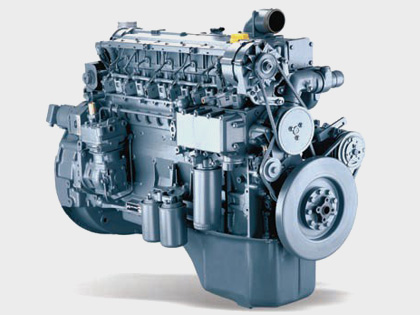
So, working engines that consumed a gasoline mixture, appeared. They are compact, fast and affordable. And all this, thanks to the pioneer of engine building, the company Deutz. In 1896, the
history of the automobile industry begins. At the same time much more powerful gasoline engines began to be installed on railroad locomotives.
However, the technical department of the company was not asleep. In 1898, a fundamentally new engine was constructed and presented to the public, having compression ignition. In honor of the
author, Rudolf Diesel, he was called a diesel engine. A new era in motor-building began.
By 1907, the design of the first sample had been worked out and patented; It was possible to start the production of diesel engines. Their consumption increased, and the size range expanded.
After the short-term production of Deutz-Bugatti cars (1907 — 1912) with the participation of the very creator, Ettore Bugatti, who worked in the company from 1907 to 1909, the management turned
its eyes to the tractors. The first machine of its own design came off the assembly line in 1924. The model was called Deutz MTN 222 and was equipped with special pulleys for driving agricultural
equipment.
At the same time, different types of engines were produced — for cars and trucks, rail cars, as well as industrial engines that were sent to other companies. Since 1921 the company was officially
called Motorenfabrik Deutz AG. In 1938 — the next transformation. Having acquired new plants, the company became known as Klockner-Humboldt-Deutz AG (KHD). In the same year, its technical
department developed another novelty — the first diesel with air cooling. However, soon everything changed abruptly. The bombing of factories by aircraft of the USSR and its allies destroys 74%
of the entire industrial potential of the concern. It was, as can be easily guessed, in late 1944 — the first half of 1945.
A new stage, called «restoration of former grandeur,» began in 1949. It was then that management decided to resurrect the production of agricultural tractors with air-cooled diesel engines. The
goods were dispersed in the market instantly. Gradually, together with the tractors, the production of trucks and buses began, which bore the brand of Magirus-Deutz and was considered one of the
best in Europe.
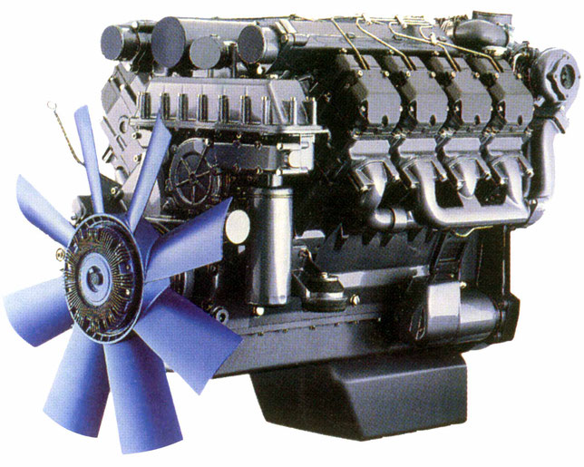
By 1964, a new Technical Center was built near Cologne, which increased the competitiveness of the structures being built. Machines with the KHD brand (dump trucks, construction chassis, diesel
engines) have been exhibited many times since 1964 at exhibitions in Moscow and have been evaluated by domestic experts. When the construction of the Baikal-Amur Mainline began, Deutz AG received
an unprecedented order for the supply in the USSR of 10,000 (!) First-class dump trucks that formed the basis of the contractors’ car fleet. Striking, but true: some of them are still on the go.
After the purchase of the USSR, the license for the right to produce Deutz diesel engines with air cooling, the specialists of the German company together with Russian engineers did a great job
of conducting full-scale tests of the motors on trucks Ural-375D, the ones for which they were intended. The design of the diesel engines was fully adapted to operation at temperatures from -40
to + 40 ° C. The work was carried out in 1966 — 1980 gg. As a result, a plant was built in Kustanai (now the Republic of Kazakhstan), designed to supply several tens of thousands of motors per
year. It was not possible to launch this enterprise before 1991, and then the Soviet Union did not. However, the experience gained in researching diesel engines under extreme conditions has
benefited both Deutz specialists and ours.
In 1975, the brand Magirus-Deutz disappeared from the automobile directories of current products. The truck and bus division was part of IVECO, a multinational concern controlled by FIAT. And the
company Deutz AG continued to engage in engine construction and tractors. In 1978, the production of a 4 millionth internal combustion engine was commemorated in the year 1867. The next such
event occurred only in 1989. And also in connection with the release of a 4 millionth diesel engine, but only with air cooling. Their production began in 1944. In 1995, the department for the
production of tractors and agricultural machines was sold to the Italian company Same Group, and the firm Deutz AG focused on where it started: the engines supplied to a wide variety of
manufacturers. «Everything has returned to normal.»
However, the history of this amazing company does not end there … There are still many interesting projects ahead of it, among them … the organization of the assembly of Deutz diesel engines
in Russia. Were you surprised? Nothing surprising. We need good diesel engines, and Russia needs Deutz AG. That’s all.
Deutz Engines 912, BF4M2012, F4M2011, BF4M2011, 1011F operators, service and maintenance manuals, error codes list, DTC, spare parts manuals & catalogues, wiring diagrams, schematics free download PDF
![]()
Deutz logo
Deutz engine manuals free download are available for free download.
| Title | File Size | Download Links |
| Deutz 2008-2009 Parts Manual [PDF] | 3.1Mb | Download |
| Deutz 2008-2009 Service Manual [PDF] | 4.4Mb | Download |
| Deutz 226B Operation Manual [PDF] | 8.5Mb | Download |
| Deutz 413 Parts Manual [PDF] | 4.5Mb | Download |
| Deutz Accessories Catalogue [PDF] | 5.2Mb | Download |
| Deutz BF4M1013C Spare Parts Catalogue [PDF] | 3Mb | Download |
| Deutz BFM 1015 Series – BF6M 1015 C, BF8M 1015, BF8M 1015 C, BF8M 1015 CP, BF6M 1015 CP Workshop Manual [PDF] | 12.3Mb | Download |
| Deutz D 2008-2009 Workshop Manual [PDF] | 4.6Mb | Download |
| Deutz D 909 / 910, B / FL 1011 / F / 2011, B / FL 912 / 913 / 914 / C, B / FL 413 F / 513 / C / CP, B / FM 1011 F 2011 Installation Manual [PDF] | 7.8Mb | Download |
| Deutz Engine D2008 2009 Workshop Manual PDF [PDF] | 3.8Mb | Download |
| Deutz Engine Fire Protection – Operation Manual [PDF] | 21.2Mb | Download |
| Deutz Engine S-BV6-8-9M628 Operation Manual [PDF] | 10Mb | Download |
| Deutz FL 411 Service Manual [PDF] | 8.7Mb | Download |
| Deutz FL 413 Service Manual [PDF] | 8.7Mb | Download |
| Deutz Serie 7 Agrotron Service Manual [PDF] | 4.1Mb | Download |
| Gt-50dz Tow Tractor With Deutz Engine [PDF] | 36.1Mb | Download |
Deutz 912
| Title | File Size | Download Links |
| Deutz 912 Parts Manual [PDF] | 4.3Mb | Download |
| Deutz 912 Technical Specifications [PDF] | 384.6kb | Download |
| Deutz 912-913 Repair Manual [PDF] | 5.8Mb | Download |
| Deutz 912-913 Service Manual [PDF] | 2.6Mb | Download |
| Deutz 912-913 Workshop Manual [PDF] | 34.5Mb | Download |
| Deutz F 3 L912 / W, F 4 L912 / W, F 5 L912 / W, B / F6 L912 / W Spare Parts Catalog [PDF] | 15.7Mb | Download |
Deutz 914
| Title | File Size | Download Links |
| Deutz 914 Parts Manual [PDF] | 4.3Mb | Download |
| Deutz 914 Service Manual [PDF] | 2.7Mb | Download |
| Deutz Engine 914 Operation Manual [PDF] | 3.2Mb | Download |
Deutz 1008
| Title | File Size | Download Links |
| Deutz – Workshop Manual BFM 1008F part 1 [PDF] | 2.5Mb | Download |
| Deutz – Workshop Manual BFM 1008F part 2 [PDF] | 2.2Mb | Download |
| Deutz Engines B / FM 1008 / F Workshop Manual [PDF] | 2.7Mb | Download |
Deutz 1011
| Title | File Size | Download Links |
| Deutz 0312 1936 2011 Workshop Manual [PDF] | 20.6Mb | Download |
| Deutz 1011 Parts Manual [PDF] | 1.9Mb | Download |
| Deutz 1011F Workshop Manual [PDF] | 4.7Mb | Download |
| Deutz BF4m1011F Engine Service Parts Manual [PDF] | 4.2Mb | Download |
| Deutz Engine 1011F Werkstatthandbuch [PDF] | 10.3Mb | Download |
| Deutz Engine 1011F Workshop Manual [PDF] | 10.6Mb | Download |
| Deutz Engine B-F L 1011F B-FM 1011F Operation Manual – Engine Description [PDF] | 1.1Mb | Download |
| Deutz Engine B-F L 1011F B-FM 1011F Operation Manual – Engine Operation [PDF] | 157.3kb | Download |
| Deutz Engine B-F L 1011F B-FM 1011F Operation Manual – Engine Preservation [PDF] | 14.2kb | Download |
| Deutz Engine B-F L 1011F B-FM 1011F Operation Manual – Faults, Causes and Remedies [PDF] | 25.1kb | Download |
| Deutz Engine B-F L 1011F B-FM 1011F Operation Manual – General [PDF] | 24.2kb | Download |
| Deutz Engine B-F L 1011F B-FM 1011F Operation Manual – Notes [PDF] | 144.3kb | Download |
| Deutz Engine B-F L 1011F B-FM 1011F Operation Manual – Operating Media [PDF] | 411.2kb | Download |
| Deutz Engine B-F L 1011F B-FM 1011F Operation Manual – Routine Maintenance [PDF] | 299.2kb | Download |
| Deutz Engine B-F L 1011F B-FM 1011F Operation Manual – Service and Maintenance [PDF] | 429.8kb | Download |
| Deutz Engine B-F L 1011F B-FM 1011F Operation Manual – Technical Specifications [PDF] | 53.8kb | Download |
| Deutz Engine B-FL 1011F Operation Manual [PDF] | 2.9Mb | Download |
| Deutz F3M 1011F, BF3M, F4M, BF4M Service Manual [PDF] | 1.3Mb | Download |
Deutz 1012 1013
| Title | File Size | Download Links |
| Deutz 1012 1013 Operation and Maintenance Manual [PDF] | 3.8Mb | Download |
| Deutz 1012-1013 Service Manual [PDF] | 3.6Mb | Download |
| Deutz Engine 1012-1013 Workshop Manual [PDF] | 4.7Mb | Download |
Deutz 1015
| Title | File Size | Download Links |
| Deutz 1015 Maintenance Manual rus [PDF] | 2.8Mb | Download |
| Deutz BFM 1015 Workshop Manual [PDF] | 3.9Mb | Download |
Deutz 2011
| Title | File Size | Download Links |
| Deutz 0312 1936 2011 Workshop Manual- competence level 3 [PDF] | 20.6Mb | Download |
| Deutz 0312 4004 2011 Workshop Manual- competence level 2 [PDF] | 7.5Mb | Download |
| Deutz 2011 – Operation Manual [PDF] | 2.7Mb | Download |
| Deutz D 2011 w, TD 2011 w, TCD 2011 w Workshop Manual- competence level 2 [PDF] | 9.9Mb | Download |
| Deutz D 2011, TD 2011 Workshop Manual- competence level 2 [PDF] | 15.8Mb | Download |
| Deutz Engine B-FL-FM 2011 Operation Manual [PDF] | 7.1Mb | Download |
| Deutz F2M 2011, F3M 2011, F4M 2011, BF3M 2011, BF4M 2011, BF3L 2011, BF4L 2011 F2L 2011, F3L 2011, F4L 2011 Operation Manual [PDF] | 5.2Mb | Download |
| Deutz F4M 2011 Technical Specifications [PDF] | 278.7kb | Download |
| Deutz F4M2011 Service Manual pdf [PDF] | 5.2Mb | Download |
Deutz 2012
| Title | File Size | Download Links |
| Deutz 2012 Service Manual [PDF] | 9.5Mb | Download |
| Deutz BF4M 2012 Operation Manual [PDF] | 4.6Mb | Download |
| Deutz BF4M2012 Workshop Manual [PDF] | 14.3Mb | Download |
| Deutz Engine 2012 Operation Manual [PDF] | 3.7Mb | Download |
| Deutz Engine BF6M 1013 Operation Manual [PDF] | 3.3Mb | Download |
| Deutz Engine BFM-2012 Workshop Manual [PDF] | 8.7Mb | Download |
Deutz TCD 2012
| Title | File Size | Download Links |
| Deutz TCD 2012-2013 Service Manual [PDF] | 3.9Mb | Download |
| Deutz TCD2012 Instruction Manual [PDF] | 5.1Mb | Download |
Deutz TCD 2013
| Title | File Size | Download Links |
| Deutz Engine TCD 2013 2V Workshop Manual [PDF] | 26.9Mb | Download |
| Deutz Engine TCD 2013 L04-06 4V Instruction Manual – Care and maintenance work [PDF] | 1017.5kb | Download |
| Engine corrosion protection [PDF] | 119kb | Download |
| Engine Description [PDF] | 2.1Mb | Download |
| Faults, causes, and remedies [PDF] | 79.7kb | Download |
| General [PDF] | 13.1kb | Download |
| Maintenance [PDF] | 493.5kb | Download |
| Operating substances [PDF] | 44.7kb | Download |
| Operation Manual [PDF] | 15.6kb | Download |
| Operation [PDF] | 151.7kb | Download |
| Service [PDF] | 22.5kb | Download |
| Technical data [PDF] | 72.2kb | Download |
| Deutz TCD 2013 4V – Industry Workshop Manual [PDF] | 535.7kb | Download |
Deutz Engine TCD 2015 Service Manual
| Title | File Size | Download Links |
| General [PDF] | 18.1kb | Download |
| Job card overview [PDF] | 20.3Mb | Download |
| Special tools [PDF] | 299.3kb | Download |
| Standard tools [PDF] | 93.2kb | Download |
| Technical data [PDF] | 185.4kb | Download |
| User notes [PDF] | 51.8kb | Download |
| Deutz TCD 2015 Service Manual [PDF] | 3.2Mb | Download |
Deutz Engines
Modern technologies and materials, top quality, dependability, durability, and longevity are all features of Deutz diesel engines manufactured in Germany. German brand engines have high specific power and torque at the lightest possible weight for power plants with such specs. As a result, Deutz engines, which use the company’s unique innovations, can function well even in the most adverse circumstances and at a high maximum load for extended periods without diminishing motor resources or increasing overhaul time, therefore saving operational expenses.
After years of research at the company’s scientific and design bureaus, Deutz engineers developed motors that balance low operating costs and little impact on the environment. Because of their low fuel consumption, power plants from the German company Deutz are among the most cost effective in the world per kilowatt-hour produced, and they conform to the strictest standards for environmental protection. This means you may save money on gasoline and put Deutz generator installations close to where people live and work.
The Deutz 413 Series consists of V-shaped (V-Twin) diesel engines with 6, 8, 10, or 12 cylinders, a horizontal selection shaft, and valves in the upper location (OHV) for use in industrial and domestic applications. Focused on usage in sub-zero temperatures (down to -30 degrees Celsius), the 137 hp. (100 kW) to 322 hp. (236 kW) range of power and forced air conditioning;
Four-stroke, overhead-valve (OHV), horizontal power-shaft (HPS), and forced-air-cooled (FAC.) Deutz 912 Series diesel engines are designed for typical circumstances and may produce anywhere from 47 horsepower (34 kilowatts) to 111 horsepower (70 kW) (82 kW). The W models have a two-stage fuel combustion mechanism;
The Deutz 913 Series consists of 4-stroke, 3, 4, and 6-cylinder diesel engines with OHV, a horizontal power shaft, and forced air cooling, designed for use in typical circumstances and ranging in output from 59 horsepower (44 kilowatts) to 191 horsepower (141 kilowatts);
The Deutz 914 Series consists of four-stroke, three-, four-, five-, and six-cylinder diesel engines designed for professional and household appliances, featuring overhead valves, a horizontal power shaft, and forced air cooling, and optimized for normal conditions of operation between 59 horsepower (44 kilowatts) and 189 horsepower (141 kilowatts);
The Deutz 912/914 Genset Series includes 19 hp (14 kW) to 97.9 hp (4-stroke, 2, 3, 4, 6, 6-cylinder, OHV, horizontal air-cooled shaft, air-cooled) diesel engines for electro generators designed for usage in normal and harsh climatic situations (73 kW) manufactured with a mechanical or electronic (optional) fuel supply regulator;
The Deutz 1008 Series is a line of four-stroke, 2, 3, and 4-cylinder diesel engines designed for use in construction machinery, featuring overhead valves (OHV), a horizontal power shaft, liquid cooling, and an emphasis on operating in harsh environments, with outputs ranging from 17.7 horsepower (13 kilowatts) to 42 horsepower (31 kilowatts).
The Deutz 1011 Series is a line of 30-liter, 4-stroke, 2-, 3-, and 4-cylinder diesel engines used in construction machinery. These engines have overhead valves (OHV), a horizontal power shaft, and liquid cooling and are optimized for usage in harsh climates. (22 kW) up to (89.5 hp) (61 kW). Gas emission regulations that are in line with those of the European Union’s STEP II and the United States CFR 40, part 89, Tier II;
The Deutz 1013 Series consists of 4-stroke, 4- and 6-cylinder diesel engines with OHV, the horizontal power shaft, liquid cooling, and an output range of 154 hp (115 kW) to 313 hp (233 kW) for use in industrial and construction equipment in both mild and severe climates.
The Deutz 1015 Series consists of 6- and 8-cylinder V-shaped diesel engines with OHV, a horizontal power shaft, liquid cooling, and an output range of 407 hp (300 kW) to 598 hp (440 kW) that are designed for usage in typical climates.
The Deutz 1013/1015 Genset Series consists of four-stroke, six- and eight-cylinder diesel engines for electric generators, with overhead valves (OHV), a horizontal power shaft, liquid cooling, and an output ranging from 103 horsepower (77 kilowatts) to 571 horsepower (362 kilowatts) (426 kW) produced using both a mechanical regulator and electronic control (as an extra);
With power ranging from 31 horsepower (23 kilowatts) to 88 horsepower (65 kilowatts), the Deutz 2011 Series consists of 2, 3, 4, and 4-cylinder diesel engines for mobile medium-power mobile equipment with OHV, horizontal power shaft, air or liquid cooling, and an emphasis on operation in normal climatic conditions; the L models feature a heat exchanger.
The Deutz TCD 2011 Series is a line of air-cooled, OHV, horizontally-mounted, 2- and 3-cylinder diesel engines for medium-power mobile equipment ranging in output from 31 to 100 horsepower (23 to 74 kilowatts) (74.9 kW). Meet the gas emission requirements of European Union (EU) STEP III and United States (US) Tier 3;
Deutz f4m2011
The Deutz 2012 Series is a line of four- and six-cylinder diesel engines designed for medium-power mobile equipment. They feature overhead valves (OHV), a horizontal power shaft, and liquid cooling and are optimized for use in typical climates. Their output ranges from 101.8 horsepower (74.9 kilowatts) to 210 horsepower (155 kilowatts).
The Deutz TCD 2012 Series is a four-stroke and six-cylinder diesel engine line designed for medium-power mobile equipment. They feature overhead valves (OHV), a horizontal power shaft, and liquid cooling and are optimized for use in temperate climates.
The Deutz 2011/2012 Genset Series consists of four-stroke 2, 3, and 4-cylinder diesel engines for electric generators with overhead valves, horizontal power shafts, liquid or air cooling, and a primary focus on operation in both normal and difficult climatic conditions, with outputs ranging from 15.5 horsepower (11.4 kilowatts) to 101 horsepower (75 kilowatts);
The Deutz TCD2013 Series is a line of four- and six-cylinder diesel engines designed for use in mobile medium-power equipment. These engines feature overhead valves (OHV), a horizontal power shaft, liquid cooling, and are optimized for use in temperate climates. Their output ranges from 173 horsepower (129 kilowatts) to 325.9 horsepower (243 kW). Meet the requirements for gas emissions set out by the European Union’s STEP III A and the United States’ Tier 3;
The Deutz TCD2013 Genset Series consists of four- and six-cylinder diesel engines with an output ranging from 121 horsepower (90 kilowatts) to 314 horsepower (234 kilowatts) with an emphasis on normal climate operating.
The Deutz TCD 2015 Series consists of 6 and 8-cylinder, OHV, the horizontal power shaft, liquid-cooled, industrial diesel engines designed for usage in typical climates and capable of producing between 489 horsepower (360 kilowatts) and 670 horsepower (500 kilowatts);
The Deutz TCD 2.9-16 liter Series consists of 4, 6, and 8-cylinder diesel engines for mobile equipment; their engine volumes range from 2.9 to 16 liters; they feature overhead valves (OHV), a horizontal power shaft, water cooling, and are optimized for use in extreme climates; their outputs range from 50 horsepower (36.9 kW) to 697 horsepower (600 lb-ft) (520 kW).