Маслоразбрызгивающие форсунки, толкатели и распредвал
- Форсунки устанавливаются на место. Чтобы они встали до упора необходимо нажать.
- Устанавливаются на место толкатели, затем распредвал.

Подшипники коленвала
-
Штихмас устанавливается на размеры:
- для ДВС 1012 – 36 мм;
- для ДВС 1013 − 38 мм.
- Производятся замеры ширины шейки коренного подшипника коленвала.
| Двигатель | Номинальная ширина шейки | Предел ремонтного размера |
|---|---|---|
| BFM 1012 | 36+0,04 мм | 36,4+0,04 мм |
| BFM 1013 | 38+0,06 мм | 38,4+0,06 мм |
- После установки вкладышей подшипника, их размещают в крышке коренного подшипника.
-
После того, как упорные кольца будут приложены к крышке упорного коренного подшипника, производятся замеры. Осевой зазор определяется, как разница между первым и вторым размерами. Например, на ДВС 1012 первый размер составляет 36,04 мм, второй – 35,90 мм. Разница 0,14 мм между ними и даст величину осевого зазора. Допускается осевой зазор в следующих пределах:
- для ДВС 1012 – от 0,1 до 0,3 мм;
- для ДВС 1013 – от 0,1 до 0,3 мм.
- На коленвале до монтажа делается отметка.
- Ставиться отметка на распредвале, после чего он должен быть правильно установлен.
- Устанавливается коленвал, необходимо добиться совмещения нанесенных отметок.

- Перед установкой упорных колец проверяется, чтобы их антифрикционный слой был обращен к щеке коленвала.
- Устанавливаются половинки, у которых нет направляющего выступа.
- Вторые половинки, у которых выступ есть, устанавливаются в крышке с нанесением смазки. Смазка используется в качестве клея. Направленность антифрикционного слоя должна быть такой же, как и примененная ранее.
- Крышка упорного коренного подшипника ставиться на место. Местонахождение крышки первого подшипника – на стороне маховика.
Внимание! У ДВС 1012 надо контролировать, чтобы бобышки смотрели на маховик.
- Дальнейшая установка крышек производится в соответствии с их номерами.

-
Закручивается крепеж в соответствии с требованиями:
Начальное усилие должно составлять:
- для ДВС 1012 – 30 Нм;
- для ДВС 1013 – 50 Нм.
Затем последовательно болты подтягиваются:
- в первый раз на 60°;
- во второй раз на 60°.
Крепеж можно использовать не больше 3 раз.
Балансирные валы ДВС 1012
- ДВС разворачивают на 180° и с помощью инструмента выкручиваются пробки.
- Ставиться на место балансирный вал таким образом, чтобы грузы смотрели в сторону уплотнителя масляного поддона.
- Регулировочный болт вкручивается в картер до конца. Нужно добиться совмещения расточек картера и вала.

- На место устанавливается упорная шайба. Необходимо ее отцентровать, ориентируясь на ось балансирного вала.
- Закручивается болт с усилием 29 Нм.
- Коленвал монтируется таким образом, чтобы первый цилиндр оказался на ВМТ. Для этого отметка на коленвале совмещается с проходящей через центры двух валов (коленчатого и распределительного) линии.
- На место ставится промежуточная шестерня. После установки на нее нажимают с легким усилием так, чтобы эта шестерня вошла в зацепление с шестерней коленвала.
- На противоположных зубьях шестерни делается отметка.
- По часовой поворачивается коленвал, величина поворота – 3 зуба.
- Затем делается поворот коленвала в противоположную сторону так, чтобы совпали расточки.
- Устанавливается коренная шейка и слегка поворачивается коленвал поочередно в противоположные стороны для того, чтобы удостовериться в достигнутой центровке коренных шеек.

- После установки на место крепежного болта его закручивают с усилием 29 Нм.
- Балансирный вал монтируется так, чтобы грузы были ориентированы уплотнителя масляного поддона.
- Болт регулировки вала вставляется в картер до конца. При этом требуется следить за совмещением расточек вала и картера.
- Упорная шайба устанавливается на место. Проводится отцентровка, ориентируясь на ось балансирного вала.
- После установки на место крепежного болта, он закручивается с усилием 29 Нм.
- При установке промежуточной шестерни необходимо следить за совмещением отверстий.

- Устанавливается коренная шейка.
- После установки на место крепежного болта его закручивают с усилием 29 Нм.
- Затем надо извлечь 2 болта для регулировки.
- Берут новые медные кольца для уплотнения и закрывают ими отверстия.
Ведущая шестерня, регулятор, рейка ТНВД
- Собирается ведущая шестерня и опорная шейка, затем они устанавливаются на место. Закручивают крепеж с усилием 21 Нм.
- Ставят на место рейку топливного насоса высокого давления, одновременно устанавливают направляющую втулку.
- На крепеж нанести средство для фиксации DW 71 и закрутить. Усилие должно составлять 10+2 Нм.

Крышка распределительных шестерен и фронтальная крышка
- В точках смазки, нанести на крышки распределительных шестерен средство для уплотнения DW 67.
- Крышка ставится на место, немного прикручивается крепеж, выравнивается деталь по отношению к уплотнителю масляного поддона. После выравнивания крепеж закручивается с усилием 21+2 Нм.
- На роторы во фронтальной крышке наносится немного масла. Уплотнитель фиксируется средством для фиксации DW 71.
- ДВС разворачивается на 180° так, чтобы уплотнитель масляного поддона смотрел вниз.
- Производится выравнивание ротора по отношению к коленвалу.
- Фронтальная крышка ставиться на место, немного прикручивается крепеж, выравнивается деталь по отношению к уплотнителю масляного поддона. После выравнивания закрутить крепеж с усилием 21+2 Нм.

Поршень и шатун
- В шатун вставляются вкладыши шатунного подшипника.
- Угол смещения замков поршневых колец должен составлять 90° — 120° между собой.
- Поршень вместе с шатуном устанавливается в БЦ так, чтобы значок, соответствующий маховику, смотрел на него.
- Необходимо надавить на шатун. Нажимать надо в сторону шатунной шейки. После этого ставиться крышка.
-
Крепеж закручивается в соответствии с требованиями:
Начальное усилие должно составлять — 30 Нм.
Затем последовательно болты подтягиваются:
- в первый раз на 60°;
- во второй раз ДВС 1012 на 30°, а ДВС 1013 на 60°.
- ДВС разворачивают на 180° и контролируется легкость перемещения шатунов.

Монтаж топливного насоса высокого давления
Провести замер хода рейки без ТНВД
- Сначала для рейки ставится стопор.
- Производится замер расстояния от стопора до той точки, где рейка остановилась.
- Производится замер расстояния от стопора до точки, где рейка начинает движение. Разница между этими расстояниями считается ходом рейки.
- Разворачивается стопор. Рукой установить рейку в точку остановки, используя стопор.
- Диск с нанесенной шкалой градусов ставится на фланец маховика, затем устанавливают стрелку.

Определение верхней мертвой точки для поршня, который относится к ТНВД
- Рейка для замера устанавливается на верхней мертвой точки. Поворачивать коленвал необходимо в сторону вращения ДВС и вращать до тех пор, пока стрелка индикатора не достигнет верхней мертвой точки. Индикатор выставляется на 0.
- Далее коленвал поворачивается в противоположную сторону на 90°. Снова изменить направление вращения коленвала. Остановить вал нужно в 8 мм от верхней мертвой точки. Диск со шкалой выставляется на 0.
- Коленвал разворачивается на 90° в том направлении, в котором вращается ДВС. Изменить направление вращения коленвала и остановить вал нужно в 8 мм от верхней мертвой точки. Записать значение в градусах. Верхняя мертвая точка – это половина полученного значения.
- Разворачивается коленвал до отметки на диске, которая соответствует половине полученного значения.
- Перестать вращать коленвал. Немного открутить болты, диск установить на 0.
- На место ставятся роликовые толкатели.

Установка момента впрыска ТНВД
-
Индикатор в приспособлении для проведения измерений выставляется на 0.
- ДВС 1012: индикатор 100 780, установочный размер – 115 мм;
- ДВС 1012: индикатор 100 860, размер – 126 мм;
- ДВС 1013: индикатор 100 840, размер – 150 мм.
- Коленвал разворачивается на 180° в направлении, противоположном вращению ДВС, после чего устанавливается соответствующий роликовый толкатель.
- Осторожно устанавливается приспособление и проводятся измерения.
- Приспособление поворачивается так, чтобы индикатор был за наружным кольцом. Стрелку на 0. Это положение предварительного хода – изменения в направлении вращений больше производиться не будут.
- Делают поворот коленвала в направлении вращения двигателя. Нужно добиться, чтобы индикатор показывал предварительный ход. Записывают угол подачи, тип распредвала и величину предварительного хода.
- Производится замер длины топливного насоса высокого давления.
- Приспособление для измерений вытаскивается и выбирается соответствующие компенсационные прокладки.
- Выбранную прокладку наложить на толкатель.
Повторить эти шаги для каждого топливного насос высокого давления.

ТНВД
Внимание! Очередность этапов работ по сборке топливного насоса высокого давления должны быть повторены для каждого насоса.
- Рычаг поворотного кулака топливного насоса высокого давления выставляется в среднее положение.
- На плоскость с предосторожностями ставится роликовый толкатель нужного цилиндра. Наносится немного масла в гнездо и на кольца уплотнения. После этого аккуратно в рейку топливного насоса высокого давления заводится рычаг поворотного кулака.
- Фланец ставится на место так, чтобы он был ориентирован на корпус топливного насоса высокого давления. На крепеж наносится немного масла, после чего он закручивается с усилием 5 Нм.
- После этого крепеж отворачивают на 60°.
- С помощью торцевого ключа аккуратно против часовой поворачивают топливный насос высокого давления пока не станет заметен упор.
- Опять закручивают крепеж на 60°. Делается это постепенно: затянуть с усилием 7 Нм, повторить − с 10 Нм и завершить – с 30 Нм. Начинают закручивать крепеж с наружного болта.

Проведение замера хода рейки (вместе с топливными насосами высокого давления)
- После откручивания и удаления стопора разворачивают приспособление.
- Производится замер расстояния от стопора до той точки, где рейка остановилась.
- Далее производится замер расстояния от стопора до точки, где рейка начинает движение. Разница между этими расстояниями считается ходом рейки.
- Снимается стопор, стрелка и диск с нанесенной шкалой.

Проверка и замер хода рейки
- Рейка должна оказывать одинаковое сопротивление, когда ее задвигают медленно. После того, как нажатие на рейку прекратилось, пружина должна вернуть ее в начальное положение.
- Измеряется ход рейки от крышки распределительных шестерен до той точки, где рейка остановилась. Это значение учитывают, если регулятор требуется поменять или отремонтировать.

Маховик и шкив клиноременной передачи
- Поставить маховик на место, используя самодельный инструмент (оправку). Вручную закрутить крепеж.
-
Придерживая деталь, закрутить крепеж согласно требованиям:
Начальная протяжка должна производиться для крепежа с размерами:
- 35-45 мм с усилием от 20 до 30 Нм;
- 50-85 мм — от 30 до 40 Нм.
Первый угол дополнительной протяжки для крепежа всех размеров − 60º.
Второй угол дополнительной протяжки для крепежа с размерами:
- 30 мм – 30°;
- 35-85 мм) – 60°.
При наличии подтверждающих документов крепеж разрешено использовать до 5 раз.
- Шкив клиноременной передачи ставится на место. Придерживая шкив, закручивается крепеж согласно требованиям:

Начальная протяжка должна производится с усилием от 40 до 50 Нм.
Первый угол дополнительной протяжки для крепежа с размерами:
- 60 мм – 60°;
- 80 мм – 60°.
Второй угол дополнительной протяжки для крепежа размерами:
- 60 мм – 30°;
- 80 мм – 60°.
При наличии подтверждающих документов крепеж разрешено использовать до 5 раз.
Головка цилиндра
- Выбирается соответствующая прокладка для головки цилиндра, индикатор устанавливается на 0.
- Индикатор устанавливается на первом поршне в точках проведения измерений и измеряется, насколько поршень максимально выступает. Такие измерения провести на каждом поршне.
-
Точки, на которые требуется обратить внимание:
ДВС 1012 – 90 мм,
ДВС 1013 – 95 мм. - Нужная прокладка ГБЦ определяется после сравнения полученных максимальных значений с таблицей.
| Двигатель | Выступание поршня | Обозначение прокладки головки цилиндра |
|---|---|---|
| ДВС 1012 | 0,43 — < 0,64 мм 0,64 — < 0,74 мм 0,74 — 0,85 мм |
1 отверстие 2 отверстия 3 отверстия |
| ДВС 1013 | 0,28 — < 0,54 мм 0,54 — < 0,64 мм 0,64 — 0,75 мм |
1 отверстие 2 отверстия 3 отверстия |
- Прокладку ГБЦ устанавливается на очищенную от грязи и масла поверхность.
Головка цилиндра с приводом клапанов ДВС 1012
- Проводится монтаж головки, короткий крепеж смазывается и закручивается не полностью. Крепеж разрешено использовать до 5 раз.
- Последовательно устанавливаются штанга толкателей и стойка оси коромысла. Затем стойку выравнивают по отношению к клапанам и штанги.
- Длинный крепеж смазывается и закручивается не полностью. Крепеж разрешено использовать до 5 раз.
- Усилие для затяжки болтов М8 – 21 Нм.
-
Крепеж головки цилиндра закручивается согласно требованиям:
- Начальная протяжка с усилием 30 Нм;
- Повторно – 80 Нм;
- Угол протяжки – 90°.

Головка цилиндра с приводом клапанов ДВС 1013
- Проводится монтаж головки, крепеж смазывается и закручивается не полностью. Крепеж разрешено использовать до 5 раз.
-
Крепеж головки цилиндра закручивается согласно требованиям:
- Начальная протяжка с усилием 50 Нм;
- Повторно – 130 Нм;
- Угол протяжки – 90°.
- Последовательно устанавливаются штанга толкателей и стойка оси коромысла. Затем стойку выравнивают по отношению к клапанам и штанги.
- Крепеж закручивается с усилием 21 Нм.
- Вставляются штифтовые свечи накаливания и закручиваются с усилием 20±2 Нм.

Электромагнитный выключатель, форсунки и топливопроводы высокого давления
- Для установки электромагнитного выключателя требуется нажать на рейку так, чтобы она встала в положение, где она останавливается. Удерживать рейку в этом положении. Установка производить с новым кольцом уплотнения, которое предварительно смазать.
- Крепеж закручивается с усилием 21 Нм.
- Форсунки ставятся после нанесения слоя смазки на новый уплотнитель.
- Затем устанавливаются прижимные скобы. Винт немного закручивают.
- Подсоединется топливопровод высокого давления. Всегда устанавливается новый, повторное использование и прогиб после подключения запрещены.
- Усилие для закручивания винта скоб составляет 16+5 Нм.
- Начальная протяжка накидных гаек — 5 Нм, вторая – 25+3,5 Нм.
- Устанавливается новый патрубок аварийного слива топлива через уплотнители. Повторное использование патрубка не допускается.
- После установки регулирующего клапана (обязательно должны стоять новые медные прокладки), с усилием 30 Нм клапан затягивают.

Впускной шланг, коллектор выпускной системы, крышка головки цилиндра, масляный радиатор
- Присоединяется впускной шланг, устанавливаются новые прокладки.
- Закручивается крепеж воздуховода системы наддува с усилием 1±+1 Нм.
- Присоединяется коллектор выпускной системы (прокладки ставят новые), на шпильки наносят пасту S1 N.S, крепеж закручивают с усилием 25±2,5 Нм.
- Устанавливается прокладка, затем крышку ГБЦ. Усилие затяжки крепежа − 9±1 Нм.
- Крепеж масляного радиатора (прокладки устанавливают новые) затягивается с усилием 21±2 Нм. Фиксаторы кабелей ставят, если они предусмотрены.
- Устанавливаются два резиновых патрубка. Крепеж затягивают с усилием 50±5 Нм.
- Патроны масляного и топливного фильтров закручиваются вручную после смазывания уплотнителя.

Насос охлаждающей жидкости, топливный насос
- Перед установкой уплотнительные кольца смазываются специальной смазкой AP25N. Вставка забивается в корпус термостата и помпы системы охлаждения.
- Затем вставляется круглый уплотнитель, предварительно нанеся на него смазку AP25N.
- Монтируется помпа системы охлаждения в сборе. По очереди закручивают крепеж с усилием 21±2 Нм.
- Температурный датчик закручивается с усилием 18±2 Нм.
- Монтируется топливный насос, затем устанавливается трубопроводы топлива с новыми прокладками.

Масляный поддон и маслозаборная труба
- После поворота ДВС на 180° устанавливается маслозаборная труба с держателем без затяжки крепежа.
- Сначала закручивается крепеж фланца овальной формы, затем держатель маслозаборной трубы. Усилие затяжки − 21±2 Нм.
- Часть прокладки, которая будет выступать, срезается. Стыки масляного поддона обрабатываются средством DW 47. На картер укладывается замененная прокладка.
- При монтаже масляного насоса обращают внимание на монтажные метки.
- Литой масляный поддон выравнивается по отношению к крышке распределительных шестерен.
-
Усилие для затяжки крепежа масляного поддона (затяжка производится по очереди):
- металлического − 21±2 Нм;
- литого − 29±2 Нм.

- Manuals
- Brands
- Deutz Manuals
- Engine
- 1012
- Operation manual
-
Contents
-
Table of Contents
-
Troubleshooting
-
Bookmarks
Quick Links
Operation Manual
1012
1013
Related Manuals for Deutz 1012
Summary of Contents for Deutz 1012
-
Page 1
Operation Manual 1012 1013… -
Page 2
The risks involved are ● When carrying out maintenance/repair op- to be borne solely by the user. erations on the engine, the use of DEUTZ ● Use in accordance with the intended pur- original parts is prescribed. These are… -
Page 3
Operation Manual 1012 1013 0297 9682 en Engine serial number: Please enter the engine serial number here. This number should be quoted when enquiring about customer service, repairs or spare parts (see Section 2.1). Technical modifications required to improve our… -
Page 4
Foreword Dear Customer, Liquid-cooled Deutz engines are designed for a large number of applications. Consequently, a wide range of variants are offered to meet the requirements of specific cases. Your engine is appropriately equipped for the installation concerned, which means that not… -
Page 5: Table Of Contents
Operating conditions Unit Engine BF6M 1013 EC 3.5.1 Winter Operation Lube Oil Circuit Schematic 3.5.2 High Ambient Temperature, High 2.3.1 Lube Oil Circuit 1012 / 1012 E Altitude 2.3.2 Lube Oil Circuit 1013 / 1013 E Fuel System 2.4.1 Fuel System Plan…
-
Page 6
6.2.6 Vent Fuel System with Fuel Pre-Filter 1012 6.7.2 Three-Phase Alternator 6.2.7 Clean/Replace/Vent Fuel Pre-Filter, 6.5.3 Changing Fan / Alternator Belts 1012 6.7.3 Lifting Tackle Filter Element 6.5.4 Tensioning Coolant / Fuel Pump Belts 6.2.8 Clean / purge or change fuel… -
Page 9: General
It goes without saying that DEUTZ Diesel Engines Special care should be taken under abnormally Original parts from DEUTZ AG are always produced meet the highest standards for environmental demanding operating conditions.
-
Page 11: Engine Description
Engine Description 2.1 Model 2.2 Engine Illustrations 2.3 Lube Oil Circuit 2.4 Fuel System 2.5 Cooling System…
-
Page 12: Rating Plate
Engine Description 2.1 Model 2.1.1 Rating Plate 2.1.2 Rating Plate Location 2.1.3 Engine Serial Number 26 332 0 26231 1 26232 1 The model A, the engine serial number B and the The rating plate C is attached to the crankcase. The engine serial number is also stamped on the performance data are stamped on the rating plate.
-
Page 13: Cylinder Numbering
Engine Description 2.1 Model 2.1.4 Cylinder Numbering 26233 0 Cylinders are numbered consecutively, beginning at the flywheel end.
-
Page 14: Engine Illustrations
Engine Description 2.2 Engine Illustrations 2.2.1 Service Side 1012 1 Oil filler (option: between filters) 2 Coolant filler 3 Cooling fan 4 Coolant pump 5 Belt pulley 6 Fuel pump 7 Engine mount 8 Fuel filter 9 Lube oil filter…
-
Page 15: Starter Side 1012
Engine Description 2.2 Engine Illustrations 2.2.2 Starter Side 1012 17 Lifting points 18 Exhaust turbocharger 19 Speed governor 20 SAE housing 21 Flywheel 22 Starter motor 23 Hydraulic oil cooler 24 Coolant heat exchanger 25 Coolant level gauge 26 Bleeder valve…
-
Page 16
Engine Description 2.2 Engine Illustrations 2.2.3 Service Side 1012 E 1 Oil filler (option: between filters) 2 Coolant inlet 3 Coolant pump 4 Alternator 5 Belt pulley 6 Engine mount 7 Fuel pump 8 Fuel filter 9 Lube oil filter… -
Page 17: Starter Side 1012 E
Engine Description 2.2 Engine Illustrations 2.2.4 Starter Side 1012 E 16 Lifting points 17 Exhaust turbocharger 18 Speed governor 19 SAE housing 20 Flywheel 21 Starter motor 22 Coolant outlet to heat exchanger 23 Exhaust manifold 24 Air intake manifold…
-
Page 18
Engine Description 2.2 Engine Illustrations 2.2.5 Service Side 1013 1 Oil filler (option: between filters) 2 Alternator 3 Coolant pump 4 Fan 5 Belt Pulley 6 Vibration damper 7 Fuel pump 8 Engine mount 9 Fuel filter 10 Lube oil filter 11 Oil pan 12 Dipstick 13 Lube oil cooler… -
Page 19: Starter Side 1013
Engine Description 2.2 Engine Illustrations 2.2.6 Starter Side 1013 19 Lifting points 20 Exhaust turbocharger 21 Speed governor 22 SAE housing 23 Flywheel 24 Starter motor 25 Coolant level gauge 26 Bleeder valve 27 Coolant filler cap 26 334 0…
-
Page 20
Engine Description 2.2 Engine Illustrations 2.2.7 Service Side 1013 E 1 Oil filler 2 Coolant pump 3 Fuel pump 4 Vibration damper 5 Fuel filter 6 Engine mount 7 Lube oil filter 8 Oil pan 9 Dipstick 10 Lube oil cooler 11 Mounting facility for hydraulic pump 12 Back leak fuel pipe with pressure-regulating valve… -
Page 21: Starter Side 1013 E
Engine Description 2.2 Engine Illustrations 2.2.8 Starter Side 1013 E 14 Lifting points 15 Crankcase breather valve 16 Speed governor 17 SAE housing 18 Flywheel 19 Starter motor 20 Exhaust turbocharger 21 Fan 22 Exhaust manifold 23 Air intake manifold 26 337 0…
-
Page 22: Starter Side
Engine Description 2.2 Engine Illustrations 2.2.9 Starter Side Unit Engine BF4M 1013 EC 1 Coolant filler neck with cap 2 Expansion tank 3 Vent line from cylinder head to expansion tank 4 Coolant line from engine crankcase to engine fluid radiator 5 Expansion line from expansion tank to radiator 6 Charge air line from exhaust turbocharger to charge-air cooler…
-
Page 23
Engine Description 2.2 Engine Illustrations 2.2.10 Service Side Unit Engine BF4M 1013 EC 3 Ventilation line from cylinder head to expansion tank 13 Charge-air line from charge-air cooler to engine 14 Protective guard 30 089 0 26 337 0… -
Page 24
Engine Description 2.2 Engine Illustrations 2.2.11 Starter Side Unit Engine BF6M 1013 EC 1 Filler neck with cap 2 Expansion tank 3 Vent line from cylinder head to expansion tank 4 Expansion line from expansion tank to coolant pump 5 Coolant line from crankcase to engine fluid radiator 6 Charge-air line from charge-air cooler to engine 7 Charge-air line from exhaust turbocharger to… -
Page 25
Engine Description 2.2 Engine Illustrations 2.2.12 Service Side Unit Engine BF6M 1013 EC 9 Engine fluid radiator 10 Charge-air cooler 11 Protective guard 30 086 0… -
Page 26: Lube Oil Circuit Schematic
Engine Description 2.3 Lube Oil Circuit 2.3.1 Lube Oil Circuit Schematic 1012 / 1012 E 1 Oil pan 2 Air intake manifold 3 Lube oil pump 3a Back leak fuel valve 3b Pressure-relief valve 4 Lube oil cooler 5 Lube oil filter…
-
Page 27
Engine Description 2.3 Lube Oil Circuit 2.3.2 Lube Oil Circuit Schematic 1013 / 1013 E 1 Oil pan 2 Air intake manifold 3 Lube oil pump 3a Back leak fuel valve 3b Pressure-relief valve 4 Lube oil cooler 5 Lube oil filter 6 Main oil gallery 7 Crankshaft bearing 8 Conrod bearing… -
Page 28: Fuel System
Engine Description 2.4 Fuel System 2.4.1 Fuel System Schematic 1 Fuel tank 2 Line to fuel pump 3 Fuel pump 4 Line to fuel filter 5 Fuel filter 6 Line to injection pumps 7 Injection pump 8 Line to injector 9 Injector 10 Back leak fuel pipe 11 Banjo bolt with pressure-regulating…
-
Page 29
Engine Description 2.5 Cooling System 2.5.1 Cooling System Schematic 1012 Coolant filler Thermostat housing Coolant pump Lube oil cooler Cylinder cooling Cylinder head cooling Heat exchanger Return from thermostat to coolant pump housing Ventilation line from cylinder head to heat… -
Page 30
Engine Description 2.5 Cooling System 2.5.2 Cooling System Schematic 1012 E entrance regulation Thermostat housing Coolant pump Lube oil cooler Cylinder cooling Cylinder head cooling Heat exchanger Ventilation line expansion tank — coolant pump Line from engine to heat exchanger… -
Page 31
Engine Description 2.5 Cooling System 1012 E escape regulation 1 Thermostat housing 2 Cooling fluid pump 3 Lubricating oil cooler 4 Cylinder cooling 5 Cylinder head cooling 6 Heat exchanger 7 Compensation setting of compensation tank t o cooling fluid pump… -
Page 32
Engine Description 2.5 Cooling System 2.5.3 Cooling System Schematic 1013 Coolant filler Thermostat housing Coolant pump Lube oil cooler Cylinder cooling Cylinder head cooling Heat exchanger Expansion line coolant pump/expansion tank Ventilation line from cylinder head to heat exchanger (expansion tank) 26 338 1… -
Page 33: 1013 E
Engine Description 2.5 Cooling System 2.5.4 Cooling System Schematic 1013 E entrance regulation Thermostat housing Coolant pump Lube oil cooler Cylinder cooling Cylinder head cooling Heat exchanger Ventilation line expansion tank — coolant pump Line from engine to heat exchanger Ventilation line from cylinder head to expansion tank 10 Expansion tank…
-
Page 34
Engine Description 2.5 Cooling System 1013 E escape regulation 1 Thermostat housing 2 Cooling fluid pump 3 Lubricating oil cooler 4 Cylinder cooling 5 Cylinder head cooling 6 Heat exchanger 7 Compensation setting of compensation tank t o cooling fluid pump 8 Line (Crankcase) from thermostat to heat exchanger 9 Ventilation line from cylinder head to… -
Page 35: Commissioning
Engine Operation 3.1 Commissioning 3.2 Starting 3.3 Monitoring Systems 3.4 Stopping 3.5 Operating Conditions…
-
Page 36
Engine Operation 3.1 Commissioning 3.1.1 Adding Engine Oil 3.1.2 Filling Oil Bath Air Cleaner 3.1.3 Adding Fuel 26243 0 24980 2 26244 0 As a rule, engines are delivered empty of oil. Fill oil cup 1 of the oil bath air cleaner (if fitted) Use only commercial-grade diesel fuel. -
Page 37
System ! 1012/1013 ! Check battery and cable connections, see See section 6.3.4 6.7.1. ! 1012 E/1013 E ! Trial run See section 6.3.6 ! Unit engine (with frontal radiator) — After the engine has been prepared, let it See section 6.3.8. -
Page 38
Engine Operation 3.2 Starting 3.2.1 Electric Starting Starting without Cold-Start Aid Make sure that no-one is stand- ing in the danger area of the engine/ machine before switch- ing on. After repairs: Check whether all protection devices are mounted and all tools have been removed from the engine. -
Page 39
Engine Operation 3.2 Starting Starting with Heater Plugs 25746 1 ● Insert key. – Position 0 = no operating voltage. ● Turn key clockwise. – Position 1 = operating voltage. – Pilot lights come on. Leave to preheat until pilot lights go out. ●… -
Page 40: Engine Oil Pressure
Engine Operation 3.3 Monitoring Systems 3.3.1 Engine Oil Pressure Oil Pressure Pilot Light Oil Pressure Gauge Oil Pressure Indicator 25752 1 25753 0 25754 0 ● The oil pressure pilot light comes on with ● The pointer must remain in the green sector ●…
-
Page 41: Coolant Temperature
Engine Operation 3.3 Monitoring Systems 3.3.2 Coolant Temperature 3.3.3 Coolant Level / Coolant Level Gauge 26246 0 26247 0 ● The coolant temperature gauge pointer should ● When the engine is cold, coolant level 1 should ● If a level switch is fitted, the engine is shut remain in the green sector most of the time.
-
Page 42
Engine Operation 3.4 Stopping 3.4.1 Engines with Mechanical 3.4.2 Engines with Electrical Shutdown Shutdown 26266 0 25746 2 ● Move speed control lever 1 to low idle. ● Turn key counterclockwise (to Position 0) and remove. The pilot lights will go out. ●… -
Page 43: Operating Conditions
Engine Operation 3.5 Operating Conditions 3.5.1 Winter Operation ● Lube Oil Viscosity ● Battery – Select the oil viscosity (SAE grade) – Efficient cold starting requires a healthy according to the ambient temperature when battery (see 6.7.1). the engine is started (see 4.1.2). –…
-
Page 44: High Ambient Temperature, High
Engine Operation 3.5 Operating Conditions 3.5.2 High Ambient Temperature, High Altitude ● As the altitude and ambient temperature rise, the density of the air tends to decrease, which affects the maximum power output of the engine, the exhaust gas quality and, in extreme cases, the starting behavior.
-
Page 45: Operating Media
Operating Media 4.1 Lube Oil 4.2 Fuel 4.3 Coolant…
-
Page 46: Viscosity
Operating Media 4.1 Lube Oil 4.1.1 Quality Grade 4.1.2 Viscosity Lube oils are differentiated by Deutz Generally, multi-grade oils shall be used. In according to their performance and quality closed heated rooms at temperatures >5°C, class. Oils of other, comparable specifications also single-grade oils can be used.
-
Page 47
P r o d u c e r Type of lube oil SAE class Availability D E U T Z DEUTZ Oil TLX-10W40FE 1 0 W- 4 0 E u r o p e A D D I N O L… -
Page 48: Winter-Grade Fuel
ASTM D 396; 1 and 2 BS 2869 Class D can be obtained by adding a flow improver Summer diesel fuel (additive). Please contact your Deutz partner. ● Jet fuel Winter diesel fuel — F34/F35/F44 (kerosene) — F54 (equivalent to diesel fuel according to…
-
Page 49: Water Quality For Coolant
A test kit (order number 1213 0382) can be 01011490 (5 litres) or 1221 1500 (210 litres). because corrosion, cavitation and freezing obtained from DEUTZ Service to check the These are nitrite-, amine- and phosphate- can lead to engine damage.
-
Page 50: Cooling System Protective Liquid
Operating Media 4.3 Coolant Cooling System Protection Cooling system capacity *) [Liters] Cooling Cooling system protective protection agent Cooling system protective liquid [Vol %] [°C] [Liters] –22 8.75 10.5 11.2 12.3 –28 10.0 10.8 12.0 12.8 14.0 –35 11.3 12.2 13.5 14.4 15.8…
-
Page 51: Routine Maintenance
Routine Maintenance 5.1 Maintenance Schedule 5.2 Maintenance Chart 5.3 Maintenance Record…
-
Page 52
Every 10 operating hours or daily Depending on the application shorter In operating hours (OH), every *E70=1012 Engines 10000OH maintenance times may be necessary. Please *E70=1013 Engines 13000OH refer to manufacturer’s operating manual. E20 E30 E40 E50 E60 E60 E70* Years # Maintenance work to be carried out only by authorised service personnel. -
Page 53
Every 10 operating hours or daily Depending on the application shorter maintenance times may be necessary. Please In operating hours (OH), every *E70 1012 Engines 10000OH refer to manufacturer’s operating manual. *E70 1013 Engines 13000OH # Maintenance work to be carried out only by… -
Page 54
2000 Bh Extended intermediate overhaul authorized trained staff 3000 Bh (EPA) Extended intermediate overhaul authorized trained staff 10 000 Bh (1012) E 70 Major overhaul authorized trained staff 12 000 Bh (1013) E 70 Major overhaul authorized trained staff… -
Page 55
Routine Maintenance 5.2 Maintenance Chart The maintenance chart shown here is supplied as self-adhesive label with each engine. It should be affixed where it can be seen clearly on the engine or driven equipment. Check that this is the case. If necessary, ask your engine or equipment supplier for a fresh supply of labels. -
Page 56
Check that this is the case. If necessary, ask your engine or equipment supplier for a fresh supply of labels. Routine work should be carried out according to the schedule in 5.1. BFM 1012 Standard engine BFM 1013… -
Page 57
Routine Maintenance 5.2 Maintenance Chart The maintenance chart shown here is supplied as self-adhesive label with each engine. It should be affixed where it can be seen clearly on the engine or driven equipment. Check that this is the case. If necessary, ask your engine or equipment supplier for a fresh supply of labels. -
Page 58
Routine Maintenance 5.3 Completed Maintenance Jobs Hours. Date Signaure / Stamp Hours Date Signaure / Stamp 50-150 1000 1125 1250 1375 1500 1625 1750 1875 2000 2115 2250 2375 2500 2625 2750 * Commissioning new and overhauled engines The maintenance jobs duly completed can be recorded in the above table. -
Page 59
Routine Maintenance 5.3 Completed Maintenance Jobs Hours Date Signaure / Stamp Hours Date Signaure / Stamp 2875 3000 3125 3250 3375 3500 3625 3750 3875 4000 4125 4250 4375 4500 4625 4750 4875 5000 5125 5250 5375 5500 5625 5750 The maintenance jobs duly completed can be recorded in the above table. -
Page 60
Routine Maintenance 5.3 Completed Maintenance Jobs Hours. Date Signaure / Stamp Hours Date Signaure / Stamp 6000 5875 6250 6125 6375 6500 6750 6625 7000 6875 7250 7125 7500 7375 7750 7625 8000 7825 8250 8125 8500 8375 8625 8750 The maintenance jobs duly completed can be recorded in the above table. -
Page 61
Hours Date Signaure / Stamp Hours Date Signaure / Stamp 9000 8875 9250 9125 9500 9375 9750 9625 10000 9875 10250 10125 10500 10375 10750 10625 11000 10825 11250 11125 11500 11375 11750 11625 The maintenance jobs duly completed can be recorded in the above table. -
Page 62
Hours. Date Signaure / Stamp Hours Date Signaure / Stamp… -
Page 63: Service And Maintenance
Service and Maintenance 6.1 Lubrication System 6.2 Fuel System 6.3 Cooling System 6.4 Combustion Air Cleaner 6.5 Belt Drives 6.6 Adjustments 6.7 Accessories…
-
Page 64: Oil Change Intervals
Service and Maintenance 6.1 Lubrication System 6.1.1 Oil Change Intervals The oil change intervals are dependent on If, for vehicle engines, lube oil change the engine application and the quality of intervals are determined by operating hours, the lube oil. the lube oil change intervals indicated in table 6.1.1.1.
-
Page 65
Service and Maintenance 6.1 Lubrication System 6.1.1.1 Lube Oil Change Intervals for Equipment Engines Lube oil grade Deutz lube oil quality class DQC I DQC II DQC III ACEA-specfication E2-96 E3-96/E5-02 E4-99 API-specfication CF/CF-4 CG-4/CH-4 Worldwide specification DHD-1 special DEUTZ release list see chap. -
Page 66
Service and Maintenance 6.1 Lubrication System 6.1.1.2 Oil change intervals for vehicle engines Lube oil-quality Deutz lube oil quality class DQC I DQC II DQC III ACEA-specification E2-96 E3-96/E5-02 E4-99 API-specification CF/CF-4 CG-4/CH-4 worldwide specification DHD-1 special DEUTZ release list see chap. -
Page 67: Checking Oil Level / Changing Engine Oil
Service and Maintenance 6.1 Lubrication System 6.1.2 Checking Oil Level / Changing Engine Oil 6.1.2.1Checking Oil Level 6.1.2.2 Changing Engine Oil © 25 729 0 © 26 022 0 © 26 023 0 Ensure that the engine or vehicle is on a Run the engine warm.
-
Page 68: Changing Oil Filter
Service and Maintenance 6.1 Lubrication System 6.1.3 Changing Oil Filter © 25 880 0 © 25 881 0 © 25 882 0 With fitted torsion lock: Clean any dirt from the filter carrier rim. Check that the cartridge is correctly seated Loosen screws and slide clamps down- against the gasket and tighten with a final wards.
-
Page 69
Service and Maintenance 6.1 Lubrication System 6.1.4 Changing Oil Filter Cup © 30 074 0 Switch off the engine. Replace rubber seal 2 and apply a small Loosen the lube oil filter cap 1 and unscrew amount of grease in an anticlockwise direction. Carefully insert the new paper filter Carefully lift the paper filter cartridge 3 out cartridge 3 in guide 4. -
Page 70: Replace Fuel Filter
Undo fuel filter cartridge with commercial tool Apply light film of oil or diesel fuel to the rubber half-turn. and spin off. gasket of the new DEUTZ original fuel filter cartridge. Open fuel stopcock. Catch any fuel. Screw in the new cartridge finger tight Check for leaks.
-
Page 71
Close the fuel shut-off valve. Apply light film of oil or diesel fuel to the Open fuel shut-off valve. Undo fuel filter cartridge with commercial rubber gasket of the new original DEUTZ Bleed fuel system, see 6.2.4. tool and spin off. fuel filter cartridge. -
Page 72: Clean/Replace Fuel Pre-Filter, Filter Element
Service and Maintenance 6.2 Fuel System 6.2.3 Clean/Replace Fuel Pre-Filter, 6.2.4 Venting the Fuel System Filter Element with Preliminary Fuel Filter Bleed: Place the fuel pan beneath the preliminary fuel filter. Loosen drain plug 4 and observe the draining fluid. When fuel instead of water starts to flow, retighten drain plug 4.
-
Page 73: Clean/Replace Fuel Pre-Filter, Filter Element
Service and Maintenance 6.2 Fuel System 6.2.5 Clean/Replace Fuel Pre-Filter, 6.2.6 Vent Fuel System with Fuel Filter Element Pre-Filter Drain Water: Place fuel collection container beneath the fuel pre-filter. Loosen drain screw 9 and watch the draining liquid, tighten the drain screw 9 when water changes to fuel.
-
Page 74: Clean/Replace/Vent Fuel Pre-Filter, Filter Element
Service and Maintenance 6.2 Fuel System 6.2.7 Clean/Replace/Vent Fuel Pre-Filter, Filter Element © 36 648 0 Open the fuel shut-off valve and bleed the Clean: Vent: system. Close the fuel shut-off valve. Loosen the vent screw 7 slightly. Check for leaks after starting the engine. Place fuel collection container beneath the Actuate the pump until fuel free from air Replace:…
-
Page 75: Clean / Purge Or Change Fuel Pre-Filter
Service and Maintenance 6.2 Fuel System 6.2.8 Clean / purge or Change Fuel Pre-Filter Changing the filter element 5: Change at least once a year or as required (drop in performance also after purging) Turn off the engine or switch to other filter in case of changeover filter Close the fuel stopcock or supply (if available)
-
Page 76: Changing Fuel Leakage Pipes
Service and Maintenance 6.2 Fuel System 6.2.9 Venting Fuel system without 6.2.10 Changing Fuel Leakage Fuel Pre-Filter Pipes © 30 034 1 © 30 901 0 © 30 084 0 Set engine controller to stop position Close fuel stopcock Mounting pressure holding valve 9: Open fuel stopcock Dismantle valve cap cover Tighten up new ring piece with bolt 5.
-
Page 77: Cooling System
Ships, gensets in enclosed Remove the service flap on the heat ex- spaces, pumps Unit engine changer (see insert). Clean as described under series 1012/1013. 1000 Vehicles on paved roads The cleaning jet must be positioned parallel to Compressed Tractors, forklift trucks, the cooling-air ducts.
-
Page 78: Draining Cooling System
Service and Maintenance 6.3 Cooling System 6.3.3 Draining Cooling System 1012 / 1013 © 30 082 0 Place container under drain plug 3. Fill/vent the cooling system: see section Unscrew cap 1. 6.3.4 Unscrew drain plug 3 fully. Drain coolant.
-
Page 79: Filling / Venting Cooling System
Service and Maintenance 6.3 Cooling System 6.3.4 Filling / Venting Cooling System 1012 / 1013 Provide DEUTZ cooling system preser- vative. Fill in the coolant tag and attach in a protected position. Remove the cooler cap (1), mount the filling aid and funnel.
-
Page 80: Draining The Cooling System
6.3.6 Filling/Venting the Cooling 6.3.5 Draining the Cooling System System 1012 E/1013 E Standard engine 1012 E / 1013 E Start engine. Run engine until the operating temperature is reached and the thermostat is open. Continue running the engine at high idling speed.
-
Page 81
Service and Maintenance 6.3 Cooling System 1013 E Short engine BFM 1013E With external cooling systems in accordance with the specifications of the manufacturer. Loosen vent plug position 2 and sealing plug position 3. Add coolant up to the maximum marking or filler limit (heater valve of the system must be opened –… -
Page 82: Draining The Cooling System
Service and Maintenance 6.3 Cooling System 6.3.7 Draining the Cooling System 6.3.8 Filling/Venting the Cooling System Unit engine (6 cylinders) Unit Engine (4 Cylinders) Unit Engine © 30 277 0 © 30 299 0 © 30 277 0 Open the cap 1 of the expansion tank. Open the cap 1 of the expansion tank.
-
Page 83: Draining The Charge-Air Cooler
Service and Maintenance 6.3 Cooling System 6.3.9 Draining the Charge-Air Cooler © 30 191 0 Loosen the drain plug 1 on the end of the charge-air cooler. Drain off any oil residues that may be remaining. Close the drain plug 1.
-
Page 84: Combustion Air Cleaner
Service and Maintenance 6.4 Combustion Air Cleaner 6.4.1 Cleaning Intervals © 25 885 1 The amount of dirt in the air cleaner depends Air cleaner servicing is needed when: on the amount of dust in the air and the size of –…
-
Page 85: Emptying Cyclone Type Precleaner
Service and Maintenance 6.4 Combustion Air Cleaner 6.4.2 Emptying Cyclone Type 6.4.3 Cleaning Oil Bath Air Precleaner Cleaner © 25 886 0 © 25 887 0 Undo wing nut 1 and remove cover 2. Turn engine off and wait about 10 minutes Clean filter housing 1 if very dirty.
-
Page 86: Dry Type Air Cleaner
Service and Maintenance 6.4 Combustion Air Cleaner 6.4.4 Dry Type Air Cleaner Filter Cartridge Dust Discharge Valve © 25 888 1 © 25 889 0 Empty dust discharge valve 1 by pressing Undo clip fasteners 1. After five air cleaner services or after apart lips of discharge slot as indicated two years at the latest, replace safety Take off hood 2 and remove cartridge 3.
-
Page 87: Belt Drives
Service and Maintenance 6.5 Belt Drives 6.5.1 Checking V-Belts 1013 1012 © 26 255 0 © 26 315 0 © 26 261 1 Inspect entire V-belt for damage. Carefully remove the gauge without altering the position of the indicator arm.
-
Page 88: Tensioning Fan / Alternator Belts
6.5.2 Tensioning Fan / 6.5.3 Changing Fan / 6.5.4 Tensioning Coolant / Alternator Belts Alternator Belts Fuel Pump Belts 1012 1012 1012 © 26 449 0 © 26 449 0 © 26 450 0 Slacken off bolts 1, 2 and 3.
-
Page 89: 1012 E
6.5.6 Tensioning Coolant / 6.5.7 Changing Coolant / Fuel Pump Belts Fuel Pump Belts Fuel Pump Belts 1012 1012 E 1012 E © 26 255 0 © 26 315 0 © 26 261 1 Remove fan belt as described in 6.5.3.
-
Page 90: Tensioning Alternator Belt 1012 E
Service and Maintenance 6.5 Belt Drives 6.5.8 Tensioning Alternator Belt 6.5.9 Changing Alternator Belt 1012 E 1012 E © 26 449 0 © 26 449 0 © 26 450 0 Slacken off bolts 1, 2 and 4. Remove fuel pump belt as described in 6.5.7.
-
Page 91: 10Tensioning / Changing Fan Belt 1013
Service and Maintenance 6.5 Belt Drives 6.5.10 Tensioning / 6.5.11 Tensioning Coolant / 6.5.12 Changing Coolant / Changing Fan Belt Fuel Pump belts Fuel Pump Belts 1013 1013 1013 © 26 345 0 © 26 450 0 © 26 450 0 Slacken off bolts 1 and 2.
-
Page 92: 1013 E
Service and Maintenance 6.5 Belt Drives 6.5.13 Tensioning /Changing 6.5.14 Tensioning Coolant /Fuel 6.5.15 Changing Coolant / Alternator Belt Pump Belts Fuel Pump Belts 1013 1013 E 1013 E © 26 449 0 © 26 380 0 © 26 383 0 Tensioning: Slacken off bolts 1 and 2.
-
Page 93: Tensioning / Changing Compressor
Service and Maintenance 6.5 Belt Drives 6.5.16 Tensioning /Changing Compressor Belt © 24 598 1 © 24 599 1 Remove hex. bolts 1. To retension belt, remove one or more shims 3 – as may be required – from inside. Place removed shim(s) outside on removed half- Take off outer half-pulley 2.
-
Page 94: Adjustments
Service and Maintenance 6.6 Adjustments 6.6.1 Checking / Adjusting Valve Clearances 19691 2 26262 1 Slacken off breather valve and swing to one Adjust valve clearance if necessary: side. – Release locknut 4. – Use screwdriver 7 to turn setscrew 5 Remove rocker cover.
-
Page 95
Service and Maintenance 6.6 Adjustments 6.6.1.1 Valve Clearance Adjustment Schematic Crankshaft Position 1: Turn crankshaft until both valves in cylinder 1 overlap (exhaust valve about to close, inlet valve about to open). Adjust clearance of valves marked in black on schematic. -
Page 96: Accessories
Service and Maintenance 6.7 Accessories 6.7.1 Battery 6.7.1.3Checking Specific 6.7.1.1Checking Battery and Cable 6.7.1.2Checking Electrolyte Gravity of Electrolyte Level Connectors © 25 895 0 © 24 232 3 © 25 896 0 Keep battery clean and dry. Remove caps 1. Measure the specific gravity of individual cells with a commercial hydrometer.
-
Page 97
Service and Maintenance 6.7 Accessories Specific Gravity in [kg/l] in °Bé [°Baumé]* State of Charge Normal Tropics Normal Tropics 1.28 1.23 Fully charged 1.20 1.12 Half charged, recharge 1.12 1.08 Discharged, recharge immediately * Measurement of specific gravity in °Bé is out of date and rarely used today. The gases emitted by the battery are explosive. -
Page 98: Three-Phase Alternator
Service and Maintenance 6.7 Accessories 6.7.2 Three-Phase Alternator 6.7.3 Lifting Tackle Notes on the three-phase system: Never disconnect the cables between bat- tery, alternator and regulator while the engine is running. If, however, it is necessary to start and ope- rate the engine without the battery, discon- nect the regulator from the alternator before starting.
-
Page 99
Troubleshooting 7.1 Diagnosis Chart 7.1 Diagnosis Chart… -
Page 100
● A diagnosis chart is given on the facing page. ● If you cannot identify the cause of the problem or are unable to rectify it yourself, please contact DEUTZ Service. Before starting, make sure that nobody is standing in the imme- diate vicinity of the engine or driven machine. -
Page 101: Troubleshooting
Troubleshooting 7.1 Diagnosis Chart Fault Remedy Engine fails or is difficult to start Check Engine starts but runs unevenly or stalls Adjust Engine overheats. Temperature monitor gives warning Replace Engine gives poor performance Clean Engine not firing on all cylinders Top up Engine has little or no oil pressure Lower level…
-
Page 102
Troubleshooting 7.1 Diagnosis Chart Fault Remedy Engine fails or is difficult to start Check Engine starts but runs unevenly or stalls Adjust Engine overheats. Temperature monitor gives warning Replace Engine gives poor performance Clean Engine not firing on all cylinders Top up Engine has little or no oil pressure Lower level… -
Page 103: Engine Preservation
Engine Preservation 8.1 Preservation 8.1 Preservation…
-
Page 104
Engine Preservation 8.1 Preservation 8.1 Preservation If the engine is to remain idle for an extended period of time, it is necessary to take protective measures to prevent rust formation. The pre- servative measures described here will protect the engine for up to 6 months. The procedure will have to be reversed before the engine is re- commissioned. -
Page 105: Technical Specification
Technical Specifications 9.1 Engine Specifications and Settings 9.2 Torque Wrench Settings 9.3 Tools…
-
Page 106: Technical Specifications
Model ————- BF4M 1012 ——— BF4M 1012 C ————— BF6M 1012 ———- BF6M 1012 C ——— ———— BF4M 1012 E ——- BF4M 1012 EC ————- BF6M 1012 E ——- BF6M 1012 EC ——- Number of cylinders ——————- 4 ———————— 4 —————————— 6 ———————— 6 —————…
-
Page 107
Model BFM1012 / E ————- BF4M 1012 ——— BF4M 1012 C ————— BF6M 1012 ———- BF6M 1012 C ——— ———— BF4M 1012 E ——- BF4M 1012 EC ————- BF6M 1012 E ——- BF6M 1012 EC ——- Cooling system ———————————————- Liquid-cooled/Cooling system protection —————————… -
Page 108
Technical Specifications 9.1 Engine Specifications and Settings Model — BF4M 1013 ——— BF4M 1013 C ——— BF6M 1013 —- BF6M 1013 C ——— BF6M 1013 CP — — BF4M 1013 E ——- BF4M 1013 EC ——- BF6M 1013 E — BF6M 1013 EC ——- BF6M 1013 ECP — Number of cylinders ———- 4 ———————- 4 ———————— 6 —————— 6 ———————— 6 ———- Cylinder arrangement… -
Page 109
Technical Specifications 9.1 Engine Specifications and Settings Model 1013 /E ————- BF4M 1013 ——— BF4M 1013 C BF6M 1013 BF6M 1013 C ——- BF6M 1013 CP ——- ———— BF4M 1013 E ——- BF4M 1013 ECBF6M 1013 EBF6M 1013 EC — BF6M 1013 ECP —— Cooling system ———————————————- Liquid-cooled/Cooling system protection ————————— Coolant quantity… -
Page 110
Technical Specifications 9.1 Engine Specifications and Settings Model ————————————- BF4M 1013 FC ———— BF6M 1013 FC ———————————- Number of cylinders ———————————————- 4 —————————— 6 —————————————— Cylinder arrangement —————————————————— vertical, in line ————————————————— Bore [mm] ———————————————————— 108 ——————————————————— Stroke [mm] ———————————————————— 130 ——————————————————— Total displacement ] ——————————————- 4764 ———————— 7146 —————————————- Compression ratio… -
Page 111
Technical Specifications 9.1 Engine Specifications and Settings Model 1013 FC ————————————- BF4M 1013 FC ———— BF6M 1013 FC ———————————- Cooling system ———————————————- Liquid-cooled/Cooling system protection ————————— Coolant quantity 1013 FC [litres approx.] ——————————————— 7.2 ————————— 9.8 —————————————— Permissible continuous coolant temperature Engine outlet, with performance group I [°C] ——————— wi t h hi n ged-type charger (turbocharger) max.110 ./ wi t h fi x ed charger (turbocharger) max.105… -
Page 112
Technical Specifications 9.2 Torque Wrench Settings Preload [Nm] Torquing Load [Nm] Location Total [Nm] Remarks Stage 1 Stage 2 Stage 3 Stage 1 Stage 2 Stage 3 Stage 4 Rocker cover Rocker arm setscrew M16 x40 8.8 Mount, flywheel side M16 x40 8.8 Mount, turbocharger side Air intake manifold… -
Page 113
A TORX wrench set is used with engines in the The V-belt tension gauge can be obtained under The hose clamp pliers can be obtained under order 1012/1013 series. This system was chosen order number 91 107 from: number 8020 from because of the many advantages it offers: WILBÄR… -
Page 114
Technical Specifications 9.2 Tools Filling aid Filling aid BFM 1012/1013 BFM 1012/1013 E 32 039 0 31 145 0 The filling aid is obtainable under order No. The filling aid is obtainable under order No. 170 150 from: 170 140 from: Fa. -
Page 115
Notes Warnings to Place on Equipment Warning in the Manual CALIFORNIA CALIFORNIA Proposition 65 Warning Proposition 65 Warning Diesel engine exhaust and some of its Diesel engine exhaust and some of its constituents are known to the State of constituents are known to the State of California to cause cancer, birth California to cause cancer, birth defects, and other reproductive harm. -
Page 116
Obligation of Resellers of Diesel Engines. This letter must accompany any loose diesel engine sold in California. Should you have any questions, please call Deutz Corporation Product Support Department. -
Page 117
Notes… -
Page 120
DEUTZ AG Supporthouse Information Systems Ottostraße 1 51149 Köln Germany Phone: +49 (0) 221-822-0 Fax: +49 (0) 221-822-5850 E-Mail: info@deutz.com www.deutz.com Printed in Germany © 07/2008 All rights reserved Order number: The engine company. 0297 9682 en…
This manual is also suitable for:
1013
- Manuals
- Brands
- Deutz Manuals
- Engine
- 1013
Manuals and User Guides for Deutz 1013. We have 3 Deutz 1013 manuals available for free PDF download: Workshop Manual, Operation Manual
Deutz 1013 Workshop Manual (490 pages)
Brand: Deutz
|
Category: Engine
|
Size: 14.62 MB
Table of Contents
-
Specifications
12
-
Schematic for Valve Clearance Adjustment
22
-
Tightening Order for Cylinder Head Bolts
23
-
Setting Commencement of Delivery
24
-
Determining Shim Thickness for Commencement of Delivery
27
-
Bosch Injection Pump
27
-
Determining Shim Thickness for Bosch Injection Pump Replacement on BFM 1012 in Case of Service. Standard Dimensions L0=109Mm
31
-
Determining Shim Thickness for Bosch Injection Pump Replacement on BFM 1012 in Case of Service. Standard Dimensions L0=119Mm
35
-
Determining Shim Thickness for Bosch Injection Pump Replacement on BFM 1013 in Case of Service. Standard Dimensions L0=143Mm
39
-
Determining Corrected Installation Dimension (Ek) and EP Code for Bosch Injection Pump
43
-
Key to Symbols
47
-
Checking and Adjusting
53
-
Valve Clearance Checking and Adjusting/Special Tool Required
54
-
Compression Pressure Checking and Adjusting
58
-
Injector Checkind and Adjusting
62
-
Engine View
70
-
Repair of Components
71
-
Crakcase with Integrated Cylinder Liners Repair
73
-
Front Cover/Lube Oil Pump Repair
97
-
Timing Chest Repair
105
-
Crankshaft Repair
111
-
Starter Ring Gear Repair
121
-
Connecting Rod Repair
125
-
Piston
139
-
Cylinder Head
147
-
Camshaft Repair
161
-
Rocker Arm Bracket
165
-
Lube Oil Cooler
169
-
Fuel Pump
181
-
Injector
185
-
Air Compressor
189
-
Injector (Cont.)
191
-
Control Rod Repair
195
-
Air Compressor Repair
201
-
Thermostat Repair
203
-
Coolant Pump Repair
207
-
Blower Repair
211
-
Mass Balancing Shaft Repair
223
-
Hydraulic Pump Drive Repair
227
-
Hydraulic Pump with Fastening Flange Repair
234
-
Disassembly and Reassembly of Complete Engine
243
-
Tools Required for Dismantling the Engine
248
-
Mounting Angled Clamping Plate
248
-
Clamp Engine in Swiveling Assembly Stand and Align
248
-
Bfm 1013
251
-
Removal of BFM 1012 Oil Pressure Pipe, Oil Return Pipe, Exhaust Turbocharger
255
-
Removal of BFM 1013 Oil Pressure Pipe, Oil Return Pipe, Charge Air Eblow and Exhaust Turbocharger
255
-
Reassembling Engine
280
-
Tools Required for the Engine Reassembly
280
-
Oil Spray Nozzles
280
-
Tappets/Camshaft
283
-
Crankshaft Hearings
283
-
Mass Balancing Shafts BFM 1012
291
-
Drive Gear/Governor
300
-
Control Rod
300
-
Timing Chest Cover
303
-
Front Cover
304
-
Piston Complete with Connecting Rod
307
-
Installing Injection Pumps
311
-
Determining TDC of Piston Pertaining to Injection Pump to be Timed
312
-
Determining Commencement of Delivery with Bosch Injection Pump
316
-
Injection Pump Assembly
320
-
Gauging Control Rod Travel with Injection Pumps Installed
324
-
Checking Ease of Movement of Control Rod
327
-
Gauging Control Rod Travel for Governor Adjustment
327
-
Flywheel/V-Belt Pulley
328
-
Cylinder Head Assembly
331
-
Cylinder Head with Valve Gear BFM 1012
335
-
Shutdown Solenoid
340
-
Injector/Injection Lines
343
-
Air Intake/Exhaust Manifold
344
-
Cylinder Head Cover
347
-
Lube Oil Cooler Mounting
348
-
Coolant Pump
351
-
Fuel Pump Fitting
355
-
Oil Suction Pipe/Oil Pan
355
-
Governor
360
-
Cable Harness
364
-
Adapter Housing
367
-
Starter
368
-
Breather Pipe
368
-
Oil Pressure Switch
371
-
Crankcase Breather
372
-
Coolant Pipe Mounting
375
-
Exhaust Turbocharger BFM 1012 Flywheel End
375
-
Adapter
375
-
Exhaust Turbocharger BFM 1013
376
-
Central Arrangement
376
-
Oil Return Pipe/Pressure Oil Pipe BFM 1012
376
-
Pressure Oil Pipe/Oil Return Pipe BFM 1013
379
-
Intake Elbow BFM 1012
383
-
Intake Elbow BFM 1013
384
-
Charge Air Elbow BFM 1013
387
-
Oil Dipstick
388
-
Alternator
391
-
Tensioning V-Belt
391
-
Engine Mounting/Mounting Feet
395
-
Removing and Refitting Components for Integrated Cooling System — BFM 1012
396
-
Removing Components
396
-
Refitting Components
412
-
Oil Pressure Switch/Coolant Temperature Sensor Refitting
412
-
Cable Harness Refitting
412
-
Blower Carrier Refitting
415
-
Vibration Damper/V-Belt Pulley Refitting
416
-
Coolant Pipe Refitting
424
-
Panelling Refitting
427
-
Oil Return Pipe/Pressure Oil Pipe Refitting
427
-
Radiator Refitting
431
-
Replacing Shafts Seals on Complete Engine
436
-
Timing Chest Cover Flywheel End
436
-
Front Cover Refitting
439
-
Removing and Refitting Air Compressor
444
-
Removing and Refitting Power Steering Pump
448
-
Removing and Refitting Hydraulic Pump
452
-
Removing and Refitting Hydraulic Pump Together with Bracket
456
-
Replacing Injection Pump in Case of Service
464
-
Commercial Tools
475
-
Pressure Pump for Coolant Leakage
475
-
Compression Tester
475
-
Nozzle Tester
475
-
Socket A/Flats 15, Long Version for Injector (Cap Nut)
476
-
Screw Driver Socket
476
-
Torx Sockets Long Version
476
-
V-Belt Tension Gauge
476
-
Serrated Wrench for Turning Injection Pump
477
-
Torx Tool Kit
477
-
Valve Spring Assembly Lever
477
-
Spring Clamp Pliers
477
-
Spring Clamp Pliers View
478
-
Auxiliary Tool for Glow Plug Cable Coupler
478
-
Special Tools
479
-
Connector for Compression Tester
479
-
Turning Gear
479
-
Dial Gauge M2T with Locking Ring
479
-
Measuring Bar with Spacers for Gauging TDC and Piston Projection
480
-
Measuring Device for Base Circle Measurement «Injection Pump and Commencement of Delivery»
480
-
Measuring Device for Measuring and Locking Control Rod
480
-
Adjusting Pin for Mass Balancing Shafts
480
-
Press-On Device for Control Rod
481
-
Graduated Disc 360 Degrees with Device for Fastening to Flywheel for TDC and COD Setting
481
-
Adapter for Graduated Disc
481
-
Extractor for Injectors, to be Used with Tool 150 800
481
-
Dolly for Injector A/Flats 11
482
-
Assembly Tool for Control Rod Sleeves
482
-
Swiveling Clamping Stand for Cylinder Head
482
-
Clamping Plate for 120 900
482
-
Piston Ring Pliers
483
-
Piston Ring Compressor
483
-
Assembly Tool for Small End Bush
483
-
Disassembly Tool for Piston Pin Circlip
483
-
Puller (Hook) for Front and Rear Crankshaft Seals
484
-
Assembly Tool for Rear Crankshaft Seal
484
-
Assembly Tool for Crankshaft Seal
484
-
Assembly Tool for Engine Balancer Bushes
484
-
Assembly Tool for Camshaft Sleeves
485
-
Assembly Tool for Cylinder Liner
485
-
Assembly Tool for Pressure Control Valve
485
-
Extractor
485
-
Special Device for Screwing off Filter Cartridge
486
-
Assembly Tool for Coolant Thermostat
486
-
Dolly for Air Compressor Gear
486
-
Engine Assembly Stand for Double-Sided Chucking
486
-
Set of Angled Clamping Plates for Double-Sided Chucking
487
-
Engine Assembly Stand for One-Sided Chucking
487
-
Set of Angled Clamping Plates for Engine with External Cooling System
487
-
Set of Angled Clamping Plates for Engine with Integrated Cooling System
487
Advertisement

Deutz 1013 Operation Manual (120 pages)
Brand: Deutz
|
Category: Engine
|
Size: 4.36 MB
Table of Contents
-
Table of Contents
5
-
1 General
9
-
2 Engine Description
11
-
Model
11
-
Rating Plate
12
-
Engine Serial Number
12
-
Cylinder Numbering
13
-
Engine Illustrations
14
-
Starter Side 1012
15
-
Starter Side 1012 E
17
-
Starter Side 1013
19
-
Starter Side 1013 E
21
-
Starter Side
22
-
Lube Oil Circuit Schematic
26
-
Fuel System
28
-
1013 E
33
-
Cooling System Schematic 1013 E
33
-
Commissioning
35
-
Starting
35
-
Engine Oil Pressure
40
-
Monitoring Systems
40
-
Coolant Temperature
41
-
Operating Conditions
43
-
Winter Operation
43
-
High Ambient Temperature, High
44
-
-
Operating Media
45
-
Viscosity
46
-
Quality Grade
46
-
Winter-Grade Fuel
48
-
Water Quality for Coolant
49
-
Preparation
49
-
Coolant Preparation
49
-
Cooling System Protective Liquid
50
-
-
5 Routine Maintenance
51
-
Maintenance Schedule
51
-
Maintenance Chart
51
-
Maintenance Record
51
-
-
6 Service and Maintenance
63
-
Lubrication System
63
-
Oil Change Intervals
64
-
Checking Oil Level / Changing Engine Oil
67
-
Changing Oil Filter
68
-
Replace Fuel Filter
70
-
Clean/Replace Fuel Pre-Filter, Filter Element
72
-
Venting the Fuel System with Preliminary Fuel Filter
72
-
Clean/Replace Fuel Pre-Filter, Filter Element
73
-
Vent Fuel System with Fuel Pre-Filter
73
-
Clean/Replace/Vent Fuel Pre-Filter, Filter Element
74
-
Clean / Purge or Change Fuel Pre-Filter
75
-
Changing Fuel Leakage Pipes
76
-
Cooling System
77
-
Cleaning Intervals
77
-
Cleaning Cooling System
77
-
Draining Cooling System
78
-
Filling / Venting Cooling System
79
-
Draining the Cooling System
80
-
1012 E / 1013 E
80
-
Filling/Venting the Cooling System
80
-
Draining the Cooling System
82
-
Unit Engine
82
-
-
Filling/Venting the Cooling System
82
-
Draining the Charge-Air Cooler
83
-
Combustion Air Cleaner
84
-
Cleaning Intervals
84
-
Emptying Cyclone Type Precleaner
85
-
Cleaning Oil Bath Air Cleaner
85
-
Dry Type Air Cleaner
86
-
Belt Drives
87
-
Checking V-Belts
87
-
-
Tensioning Fan / Alternator Belts
88
-
Changing Fan / Alternator Belts 1012
88
-
Tensioning Coolant / Fuel Pump Belts 1012 E 8. 6.5.7 Changing Coolant / Fuel Pump Belts
88
-
Changing Coolant / Fuel Pump Belts
88
-
1012 E
89
-
-
Tensioning Alternator Belt 1012 E
90
-
Changing Alternator Belt 1012 E
90
-
10Tensioning / Changing Fan Belt 1013
91
-
11Tensioning Coolant / Fuel Pump Belts
91
-
1013 E
92
-
Tensioning / Changing Alternator
92
-
Tensioning / Changing Compressor
93
-
-
Adjustments
94
-
-
Checking / Adjusting Valve
94
-
Clearances
94
-
-
Accessories
96
-
Battery
96
-
Checking Battery and Cable Connectors
96
-
Checking Electrolyte Level
96
-
Checking Specific Gravity of Electrolyte
96
-
Three-Phase Alternator
98
-
Lifting Tackle
98
-
Troubleshooting
101
-
-
7 Faults, Causes and Remedies
103
-
8 Engine Preservation
103
-
Preservation
103
-
-
Technical Specification
105
-
Engine Specifications and Settings
105
-
Tools
105
-
Technical Specifications
106
-
Deutz 1013 Operation Manual (104 pages)
Liquid-cooled engines
Brand: Deutz
|
Category: Engine
|
Size: 3.14 MB
Table of Contents
-
Engine Serial Number
3
-
Table of Contents
5
-
1 General
9
-
2 Engine Description
11
-
Model
11
-
Cooling System
11
-
Cooling System Schematic 1012 E
30
-
Cooling System Schematic 1013 E
33
-
-
3 Engine Operation
35
-
Commissioning
35
-
Adding Engine Oil
36
-
Filling Oil Bath Air Cleaner
36
-
Adding Fuel
36
-
-
Other Preparations
37
-
Starting
38
-
Electric Starting
38
-
Monitoring Systems
40
-
Engine Oil Pressure
40
-
Coolant Temperature
41
-
Coolant Level/Level Gauge 3.4 Stopping
41
-
-
Engines with Electrical Shutdown
42
-
Operating Conditions
43
-
Winter Operation
43
-
High Ambient Temperature, High Altitude
44
-
-
4 Operating Media
45
-
Lube Oil
45
-
Quality Grade
46
-
Fuel
47
-
Winter Grade Fuel
47
-
Coolant
48
-
Coolant Preparation
48
-
-
5 Routine Maintenance
50
-
Maintenance Schedule
50
-
Maintenance Chart
50
-
Maintenance Record
50
-
-
6 Service and Maintenance
60
-
Lubrication System
60
-
Oil Change Intervals
61
-
Cleaning/Changing Oil Filter (Cup)
64
-
Fuel System
65
-
Changing Fuel Pre-Filter
65
-
Changing Fuel Leakage Pipes
67
-
Cooling System
68
-
Cleaning Intervals
68
-
-
Cleaning Cooling System
68
-
Filling / Venting Cooling System 1012 / 1013
69
-
Draining the Charge Air Cooler
72
-
Combustion Air Cleaner
73
-
Cleaning Intervals
73
-
-
Cleaning Oil Bath Air Cleaner
74
-
Belt Drives
76
-
Checking V-Belts
76
-
-
Tensioning Fan / Alternator Belts 1012
77
-
Changing Fan / Alternator Belts 1012
77
-
Tensioning Coolant / Fuel Pump Belts 1012
77
-
Changing Coolant / Fuel Pump Belts 1012
78
-
1012 E
78
-
-
Changing Alternator Belt 1012 E
79
-
Tensioning Coolant / Fuel Pump Belts
80
-
Changing Coolant / Fuel Pump Belts
80
-
Tensioning /Changing Alternator Belt
81
-
Tensioning Coolant / Fuel Pump Belts 1013 E
81
-
Changing Coolant / Fuel Pump Belts 1013 E
81
-
Tensioning / Changing Compressor Belt
82
-
Adjustments
83
-
-
Checking / Adjusting Valve Clearances
83
-
Valve Clearance Adjustment Schematic
84
-
Accessories
85
-
Checking the Battery and Cable
85
-
Checking Electrolyte Level
85
-
Checking Specific Gravity of Electrolyte
85
-
Three-Phase Alternator
87
-
Troubleshooting
88
-
Troubleshooting
90
-
Engine Preservation
92
-
Engine Preservation
93
-
Technical Specifications
94
-
Technical Specifications
95
-
Torque Wrench Settings
101
-
Service
104
-
-
-
Advertisement
Advertisement
Related Products
-
Deutz 1012
-
Deutz 1015
-
Deutz 0297 9929en
-
Deutz 914
-
Deutz 9929en
-
Deutz B/FL 1011 / F / 2011
-
Deutz B/FL 413 F / 513 /C / CP
-
Deutz B/FL 912/913/914/C
-
Deutz B/FM 1011 F / 2011
-
Deutz BF3L 2011
Deutz Categories
Engine
Toy
Inverter
Measuring Instruments
Controller
More Deutz Manuals
-
Page 1
Operation Manual 1012 1013… -
Page 2
The risks involved are ● When carrying out maintenance/repair op- to be borne solely by the user. erations on the engine, the use of DEUTZ ● Use in accordance with the intended pur- original parts is prescribed. These are… -
Page 3
Operation Manual 1012 1013 0297 9682 en Engine serial number: Please enter the engine serial number here. This number should be quoted when enquiring about customer service, repairs or spare parts (see Section 2.1). Technical modifications required to improve our… -
Page 4
Foreword Dear Customer, Liquid-cooled Deutz engines are designed for a large number of applications. Consequently, a wide range of variants are offered to meet the requirements of specific cases. Your engine is appropriately equipped for the installation concerned, which means that not… -
Page 5: Table Of Contents
Operating conditions Unit Engine BF6M 1013 EC 3.5.1 Winter Operation Lube Oil Circuit Schematic 3.5.2 High Ambient Temperature, High 2.3.1 Lube Oil Circuit 1012 / 1012 E Altitude 2.3.2 Lube Oil Circuit 1013 / 1013 E Fuel System 2.4.1 Fuel System Plan…
-
Page 6
6.2.6 Vent Fuel System with Fuel Pre-Filter 1012 6.7.2 Three-Phase Alternator 6.2.7 Clean/Replace/Vent Fuel Pre-Filter, 6.5.3 Changing Fan / Alternator Belts 1012 6.7.3 Lifting Tackle Filter Element 6.5.4 Tensioning Coolant / Fuel Pump Belts 6.2.8 Clean / purge or change fuel… -
Page 9: General
It goes without saying that DEUTZ Diesel Engines Special care should be taken under abnormally Original parts from DEUTZ AG are always produced meet the highest standards for environmental demanding operating conditions.
-
Page 11: Engine Description
Engine Description 2.1 Model 2.2 Engine Illustrations 2.3 Lube Oil Circuit 2.4 Fuel System 2.5 Cooling System…
-
Page 12: Rating Plate
Engine Description 2.1 Model 2.1.1 Rating Plate 2.1.2 Rating Plate Location 2.1.3 Engine Serial Number 26 332 0 26231 1 26232 1 The model A, the engine serial number B and the The rating plate C is attached to the crankcase. The engine serial number is also stamped on the performance data are stamped on the rating plate.
-
Page 13: Cylinder Numbering
Engine Description 2.1 Model 2.1.4 Cylinder Numbering 26233 0 Cylinders are numbered consecutively, beginning at the flywheel end.
-
Page 14: Engine Illustrations
Engine Description 2.2 Engine Illustrations 2.2.1 Service Side 1012 1 Oil filler (option: between filters) 2 Coolant filler 3 Cooling fan 4 Coolant pump 5 Belt pulley 6 Fuel pump 7 Engine mount 8 Fuel filter 9 Lube oil filter…
-
Page 15: Starter Side 1012
Engine Description 2.2 Engine Illustrations 2.2.2 Starter Side 1012 17 Lifting points 18 Exhaust turbocharger 19 Speed governor 20 SAE housing 21 Flywheel 22 Starter motor 23 Hydraulic oil cooler 24 Coolant heat exchanger 25 Coolant level gauge 26 Bleeder valve…
-
Page 16
Engine Description 2.2 Engine Illustrations 2.2.3 Service Side 1012 E 1 Oil filler (option: between filters) 2 Coolant inlet 3 Coolant pump 4 Alternator 5 Belt pulley 6 Engine mount 7 Fuel pump 8 Fuel filter 9 Lube oil filter… -
Page 17: Starter Side 1012 E
Engine Description 2.2 Engine Illustrations 2.2.4 Starter Side 1012 E 16 Lifting points 17 Exhaust turbocharger 18 Speed governor 19 SAE housing 20 Flywheel 21 Starter motor 22 Coolant outlet to heat exchanger 23 Exhaust manifold 24 Air intake manifold…
-
Page 18
Engine Description 2.2 Engine Illustrations 2.2.5 Service Side 1013 1 Oil filler (option: between filters) 2 Alternator 3 Coolant pump 4 Fan 5 Belt Pulley 6 Vibration damper 7 Fuel pump 8 Engine mount 9 Fuel filter 10 Lube oil filter 11 Oil pan 12 Dipstick 13 Lube oil cooler… -
Page 19: Starter Side 1013
Engine Description 2.2 Engine Illustrations 2.2.6 Starter Side 1013 19 Lifting points 20 Exhaust turbocharger 21 Speed governor 22 SAE housing 23 Flywheel 24 Starter motor 25 Coolant level gauge 26 Bleeder valve 27 Coolant filler cap 26 334 0…
-
Page 20
Engine Description 2.2 Engine Illustrations 2.2.7 Service Side 1013 E 1 Oil filler 2 Coolant pump 3 Fuel pump 4 Vibration damper 5 Fuel filter 6 Engine mount 7 Lube oil filter 8 Oil pan 9 Dipstick 10 Lube oil cooler 11 Mounting facility for hydraulic pump 12 Back leak fuel pipe with pressure-regulating valve… -
Page 21: Starter Side 1013 E
Engine Description 2.2 Engine Illustrations 2.2.8 Starter Side 1013 E 14 Lifting points 15 Crankcase breather valve 16 Speed governor 17 SAE housing 18 Flywheel 19 Starter motor 20 Exhaust turbocharger 21 Fan 22 Exhaust manifold 23 Air intake manifold 26 337 0…
-
Page 22: Starter Side
Engine Description 2.2 Engine Illustrations 2.2.9 Starter Side Unit Engine BF4M 1013 EC 1 Coolant filler neck with cap 2 Expansion tank 3 Vent line from cylinder head to expansion tank 4 Coolant line from engine crankcase to engine fluid radiator 5 Expansion line from expansion tank to radiator 6 Charge air line from exhaust turbocharger to charge-air cooler…
-
Page 23
Engine Description 2.2 Engine Illustrations 2.2.10 Service Side Unit Engine BF4M 1013 EC 3 Ventilation line from cylinder head to expansion tank 13 Charge-air line from charge-air cooler to engine 14 Protective guard 30 089 0 26 337 0… -
Page 24
Engine Description 2.2 Engine Illustrations 2.2.11 Starter Side Unit Engine BF6M 1013 EC 1 Filler neck with cap 2 Expansion tank 3 Vent line from cylinder head to expansion tank 4 Expansion line from expansion tank to coolant pump 5 Coolant line from crankcase to engine fluid radiator 6 Charge-air line from charge-air cooler to engine 7 Charge-air line from exhaust turbocharger to… -
Page 25
Engine Description 2.2 Engine Illustrations 2.2.12 Service Side Unit Engine BF6M 1013 EC 9 Engine fluid radiator 10 Charge-air cooler 11 Protective guard 30 086 0… -
Page 26: Lube Oil Circuit Schematic
Engine Description 2.3 Lube Oil Circuit 2.3.1 Lube Oil Circuit Schematic 1012 / 1012 E 1 Oil pan 2 Air intake manifold 3 Lube oil pump 3a Back leak fuel valve 3b Pressure-relief valve 4 Lube oil cooler 5 Lube oil filter…
-
Page 27
Engine Description 2.3 Lube Oil Circuit 2.3.2 Lube Oil Circuit Schematic 1013 / 1013 E 1 Oil pan 2 Air intake manifold 3 Lube oil pump 3a Back leak fuel valve 3b Pressure-relief valve 4 Lube oil cooler 5 Lube oil filter 6 Main oil gallery 7 Crankshaft bearing 8 Conrod bearing… -
Page 28: Fuel System
Engine Description 2.4 Fuel System 2.4.1 Fuel System Schematic 1 Fuel tank 2 Line to fuel pump 3 Fuel pump 4 Line to fuel filter 5 Fuel filter 6 Line to injection pumps 7 Injection pump 8 Line to injector 9 Injector 10 Back leak fuel pipe 11 Banjo bolt with pressure-regulating…
-
Page 29
Engine Description 2.5 Cooling System 2.5.1 Cooling System Schematic 1012 Coolant filler Thermostat housing Coolant pump Lube oil cooler Cylinder cooling Cylinder head cooling Heat exchanger Return from thermostat to coolant pump housing Ventilation line from cylinder head to heat… -
Page 30
Engine Description 2.5 Cooling System 2.5.2 Cooling System Schematic 1012 E entrance regulation Thermostat housing Coolant pump Lube oil cooler Cylinder cooling Cylinder head cooling Heat exchanger Ventilation line expansion tank — coolant pump Line from engine to heat exchanger… -
Page 31
Engine Description 2.5 Cooling System 1012 E escape regulation 1 Thermostat housing 2 Cooling fluid pump 3 Lubricating oil cooler 4 Cylinder cooling 5 Cylinder head cooling 6 Heat exchanger 7 Compensation setting of compensation tank t o cooling fluid pump… -
Page 32
Engine Description 2.5 Cooling System 2.5.3 Cooling System Schematic 1013 Coolant filler Thermostat housing Coolant pump Lube oil cooler Cylinder cooling Cylinder head cooling Heat exchanger Expansion line coolant pump/expansion tank Ventilation line from cylinder head to heat exchanger (expansion tank) 26 338 1… -
Page 33: 1013 E
Engine Description 2.5 Cooling System 2.5.4 Cooling System Schematic 1013 E entrance regulation Thermostat housing Coolant pump Lube oil cooler Cylinder cooling Cylinder head cooling Heat exchanger Ventilation line expansion tank — coolant pump Line from engine to heat exchanger Ventilation line from cylinder head to expansion tank 10 Expansion tank…
-
Page 34
Engine Description 2.5 Cooling System 1013 E escape regulation 1 Thermostat housing 2 Cooling fluid pump 3 Lubricating oil cooler 4 Cylinder cooling 5 Cylinder head cooling 6 Heat exchanger 7 Compensation setting of compensation tank t o cooling fluid pump 8 Line (Crankcase) from thermostat to heat exchanger 9 Ventilation line from cylinder head to… -
Page 35: Commissioning
Engine Operation 3.1 Commissioning 3.2 Starting 3.3 Monitoring Systems 3.4 Stopping 3.5 Operating Conditions…
-
Page 36
Engine Operation 3.1 Commissioning 3.1.1 Adding Engine Oil 3.1.2 Filling Oil Bath Air Cleaner 3.1.3 Adding Fuel 26243 0 24980 2 26244 0 As a rule, engines are delivered empty of oil. Fill oil cup 1 of the oil bath air cleaner (if fitted) Use only commercial-grade diesel fuel. -
Page 37
System ! 1012/1013 ! Check battery and cable connections, see See section 6.3.4 6.7.1. ! 1012 E/1013 E ! Trial run See section 6.3.6 ! Unit engine (with frontal radiator) — After the engine has been prepared, let it See section 6.3.8. -
Page 38
Engine Operation 3.2 Starting 3.2.1 Electric Starting Starting without Cold-Start Aid Make sure that no-one is stand- ing in the danger area of the engine/ machine before switch- ing on. After repairs: Check whether all protection devices are mounted and all tools have been removed from the engine. -
Page 39
Engine Operation 3.2 Starting Starting with Heater Plugs 25746 1 ● Insert key. – Position 0 = no operating voltage. ● Turn key clockwise. – Position 1 = operating voltage. – Pilot lights come on. Leave to preheat until pilot lights go out. ●… -
Page 40: Engine Oil Pressure
Engine Operation 3.3 Monitoring Systems 3.3.1 Engine Oil Pressure Oil Pressure Pilot Light Oil Pressure Gauge Oil Pressure Indicator 25752 1 25753 0 25754 0 ● The oil pressure pilot light comes on with ● The pointer must remain in the green sector ●…
-
Page 41: Coolant Temperature
Engine Operation 3.3 Monitoring Systems 3.3.2 Coolant Temperature 3.3.3 Coolant Level / Coolant Level Gauge 26246 0 26247 0 ● The coolant temperature gauge pointer should ● When the engine is cold, coolant level 1 should ● If a level switch is fitted, the engine is shut remain in the green sector most of the time.
-
Page 42
Engine Operation 3.4 Stopping 3.4.1 Engines with Mechanical 3.4.2 Engines with Electrical Shutdown Shutdown 26266 0 25746 2 ● Move speed control lever 1 to low idle. ● Turn key counterclockwise (to Position 0) and remove. The pilot lights will go out. ●… -
Page 43: Operating Conditions
Engine Operation 3.5 Operating Conditions 3.5.1 Winter Operation ● Lube Oil Viscosity ● Battery – Select the oil viscosity (SAE grade) – Efficient cold starting requires a healthy according to the ambient temperature when battery (see 6.7.1). the engine is started (see 4.1.2). –…
-
Page 44: High Ambient Temperature, High
Engine Operation 3.5 Operating Conditions 3.5.2 High Ambient Temperature, High Altitude ● As the altitude and ambient temperature rise, the density of the air tends to decrease, which affects the maximum power output of the engine, the exhaust gas quality and, in extreme cases, the starting behavior.
-
Page 45: Operating Media
Operating Media 4.1 Lube Oil 4.2 Fuel 4.3 Coolant…
-
Page 46: Viscosity
Operating Media 4.1 Lube Oil 4.1.1 Quality Grade 4.1.2 Viscosity Lube oils are differentiated by Deutz Generally, multi-grade oils shall be used. In according to their performance and quality closed heated rooms at temperatures >5°C, class. Oils of other, comparable specifications also single-grade oils can be used.
-
Page 47
P r o d u c e r Type of lube oil SAE class Availability D E U T Z DEUTZ Oil TLX-10W40FE 1 0 W- 4 0 E u r o p e A D D I N O L… -
Page 48: Winter-Grade Fuel
ASTM D 396; 1 and 2 BS 2869 Class D can be obtained by adding a flow improver Summer diesel fuel (additive). Please contact your Deutz partner. ● Jet fuel Winter diesel fuel — F34/F35/F44 (kerosene) — F54 (equivalent to diesel fuel according to…
-
Page 49: Water Quality For Coolant
A test kit (order number 1213 0382) can be 01011490 (5 litres) or 1221 1500 (210 litres). because corrosion, cavitation and freezing obtained from DEUTZ Service to check the These are nitrite-, amine- and phosphate- can lead to engine damage.
-
Page 50: Cooling System Protective Liquid
Operating Media 4.3 Coolant Cooling System Protection Cooling system capacity *) [Liters] Cooling Cooling system protective protection agent Cooling system protective liquid [Vol %] [°C] [Liters] –22 8.75 10.5 11.2 12.3 –28 10.0 10.8 12.0 12.8 14.0 –35 11.3 12.2 13.5 14.4 15.8…
-
Page 51: Routine Maintenance
Routine Maintenance 5.1 Maintenance Schedule 5.2 Maintenance Chart 5.3 Maintenance Record…
-
Page 52
Every 10 operating hours or daily Depending on the application shorter In operating hours (OH), every *E70=1012 Engines 10000OH maintenance times may be necessary. Please *E70=1013 Engines 13000OH refer to manufacturer’s operating manual. E20 E30 E40 E50 E60 E60 E70* Years # Maintenance work to be carried out only by authorised service personnel. -
Page 53
Every 10 operating hours or daily Depending on the application shorter maintenance times may be necessary. Please In operating hours (OH), every *E70 1012 Engines 10000OH refer to manufacturer’s operating manual. *E70 1013 Engines 13000OH # Maintenance work to be carried out only by… -
Page 54
2000 Bh Extended intermediate overhaul authorized trained staff 3000 Bh (EPA) Extended intermediate overhaul authorized trained staff 10 000 Bh (1012) E 70 Major overhaul authorized trained staff 12 000 Bh (1013) E 70 Major overhaul authorized trained staff… -
Page 55
Routine Maintenance 5.2 Maintenance Chart The maintenance chart shown here is supplied as self-adhesive label with each engine. It should be affixed where it can be seen clearly on the engine or driven equipment. Check that this is the case. If necessary, ask your engine or equipment supplier for a fresh supply of labels. -
Page 56
Check that this is the case. If necessary, ask your engine or equipment supplier for a fresh supply of labels. Routine work should be carried out according to the schedule in 5.1. BFM 1012 Standard engine BFM 1013… -
Page 57
Routine Maintenance 5.2 Maintenance Chart The maintenance chart shown here is supplied as self-adhesive label with each engine. It should be affixed where it can be seen clearly on the engine or driven equipment. Check that this is the case. If necessary, ask your engine or equipment supplier for a fresh supply of labels. -
Page 58
Routine Maintenance 5.3 Completed Maintenance Jobs Hours. Date Signaure / Stamp Hours Date Signaure / Stamp 50-150 1000 1125 1250 1375 1500 1625 1750 1875 2000 2115 2250 2375 2500 2625 2750 * Commissioning new and overhauled engines The maintenance jobs duly completed can be recorded in the above table. -
Page 59
Routine Maintenance 5.3 Completed Maintenance Jobs Hours Date Signaure / Stamp Hours Date Signaure / Stamp 2875 3000 3125 3250 3375 3500 3625 3750 3875 4000 4125 4250 4375 4500 4625 4750 4875 5000 5125 5250 5375 5500 5625 5750 The maintenance jobs duly completed can be recorded in the above table. -
Page 60
Routine Maintenance 5.3 Completed Maintenance Jobs Hours. Date Signaure / Stamp Hours Date Signaure / Stamp 6000 5875 6250 6125 6375 6500 6750 6625 7000 6875 7250 7125 7500 7375 7750 7625 8000 7825 8250 8125 8500 8375 8625 8750 The maintenance jobs duly completed can be recorded in the above table. -
Page 61
Hours Date Signaure / Stamp Hours Date Signaure / Stamp 9000 8875 9250 9125 9500 9375 9750 9625 10000 9875 10250 10125 10500 10375 10750 10625 11000 10825 11250 11125 11500 11375 11750 11625 The maintenance jobs duly completed can be recorded in the above table. -
Page 62
Hours. Date Signaure / Stamp Hours Date Signaure / Stamp… -
Page 63: Service And Maintenance
Service and Maintenance 6.1 Lubrication System 6.2 Fuel System 6.3 Cooling System 6.4 Combustion Air Cleaner 6.5 Belt Drives 6.6 Adjustments 6.7 Accessories…
-
Page 64: Oil Change Intervals
Service and Maintenance 6.1 Lubrication System 6.1.1 Oil Change Intervals The oil change intervals are dependent on If, for vehicle engines, lube oil change the engine application and the quality of intervals are determined by operating hours, the lube oil. the lube oil change intervals indicated in table 6.1.1.1.
-
Page 65
Service and Maintenance 6.1 Lubrication System 6.1.1.1 Lube Oil Change Intervals for Equipment Engines Lube oil grade Deutz lube oil quality class DQC I DQC II DQC III ACEA-specfication E2-96 E3-96/E5-02 E4-99 API-specfication CF/CF-4 CG-4/CH-4 Worldwide specification DHD-1 special DEUTZ release list see chap. -
Page 66
Service and Maintenance 6.1 Lubrication System 6.1.1.2 Oil change intervals for vehicle engines Lube oil-quality Deutz lube oil quality class DQC I DQC II DQC III ACEA-specification E2-96 E3-96/E5-02 E4-99 API-specification CF/CF-4 CG-4/CH-4 worldwide specification DHD-1 special DEUTZ release list see chap. -
Page 67: Checking Oil Level / Changing Engine Oil
Service and Maintenance 6.1 Lubrication System 6.1.2 Checking Oil Level / Changing Engine Oil 6.1.2.1Checking Oil Level 6.1.2.2 Changing Engine Oil © 25 729 0 © 26 022 0 © 26 023 0 Ensure that the engine or vehicle is on a Run the engine warm.
-
Page 68: Changing Oil Filter
Service and Maintenance 6.1 Lubrication System 6.1.3 Changing Oil Filter © 25 880 0 © 25 881 0 © 25 882 0 With fitted torsion lock: Clean any dirt from the filter carrier rim. Check that the cartridge is correctly seated Loosen screws and slide clamps down- against the gasket and tighten with a final wards.
-
Page 69
Service and Maintenance 6.1 Lubrication System 6.1.4 Changing Oil Filter Cup © 30 074 0 Switch off the engine. Replace rubber seal 2 and apply a small Loosen the lube oil filter cap 1 and unscrew amount of grease in an anticlockwise direction. Carefully insert the new paper filter Carefully lift the paper filter cartridge 3 out cartridge 3 in guide 4. -
Page 70: Replace Fuel Filter
Undo fuel filter cartridge with commercial tool Apply light film of oil or diesel fuel to the rubber half-turn. and spin off. gasket of the new DEUTZ original fuel filter cartridge. Open fuel stopcock. Catch any fuel. Screw in the new cartridge finger tight Check for leaks.
-
Page 71
Close the fuel shut-off valve. Apply light film of oil or diesel fuel to the Open fuel shut-off valve. Undo fuel filter cartridge with commercial rubber gasket of the new original DEUTZ Bleed fuel system, see 6.2.4. tool and spin off. fuel filter cartridge. -
Page 72: Clean/Replace Fuel Pre-Filter, Filter Element
Service and Maintenance 6.2 Fuel System 6.2.3 Clean/Replace Fuel Pre-Filter, 6.2.4 Venting the Fuel System Filter Element with Preliminary Fuel Filter Bleed: Place the fuel pan beneath the preliminary fuel filter. Loosen drain plug 4 and observe the draining fluid. When fuel instead of water starts to flow, retighten drain plug 4.
-
Page 73: Clean/Replace Fuel Pre-Filter, Filter Element
Service and Maintenance 6.2 Fuel System 6.2.5 Clean/Replace Fuel Pre-Filter, 6.2.6 Vent Fuel System with Fuel Filter Element Pre-Filter Drain Water: Place fuel collection container beneath the fuel pre-filter. Loosen drain screw 9 and watch the draining liquid, tighten the drain screw 9 when water changes to fuel.
-
Page 74: Clean/Replace/Vent Fuel Pre-Filter, Filter Element
Service and Maintenance 6.2 Fuel System 6.2.7 Clean/Replace/Vent Fuel Pre-Filter, Filter Element © 36 648 0 Open the fuel shut-off valve and bleed the Clean: Vent: system. Close the fuel shut-off valve. Loosen the vent screw 7 slightly. Check for leaks after starting the engine. Place fuel collection container beneath the Actuate the pump until fuel free from air Replace:…
-
Page 75: Clean / Purge Or Change Fuel Pre-Filter
Service and Maintenance 6.2 Fuel System 6.2.8 Clean / purge or Change Fuel Pre-Filter Changing the filter element 5: Change at least once a year or as required (drop in performance also after purging) Turn off the engine or switch to other filter in case of changeover filter Close the fuel stopcock or supply (if available)
-
Page 76: Changing Fuel Leakage Pipes
Service and Maintenance 6.2 Fuel System 6.2.9 Venting Fuel system without 6.2.10 Changing Fuel Leakage Fuel Pre-Filter Pipes © 30 034 1 © 30 901 0 © 30 084 0 Set engine controller to stop position Close fuel stopcock Mounting pressure holding valve 9: Open fuel stopcock Dismantle valve cap cover Tighten up new ring piece with bolt 5.
-
Page 77: Cooling System
Ships, gensets in enclosed Remove the service flap on the heat ex- spaces, pumps Unit engine changer (see insert). Clean as described under series 1012/1013. 1000 Vehicles on paved roads The cleaning jet must be positioned parallel to Compressed Tractors, forklift trucks, the cooling-air ducts.
-
Page 78: Draining Cooling System
Service and Maintenance 6.3 Cooling System 6.3.3 Draining Cooling System 1012 / 1013 © 30 082 0 Place container under drain plug 3. Fill/vent the cooling system: see section Unscrew cap 1. 6.3.4 Unscrew drain plug 3 fully. Drain coolant.
-
Page 79: Filling / Venting Cooling System
Service and Maintenance 6.3 Cooling System 6.3.4 Filling / Venting Cooling System 1012 / 1013 Provide DEUTZ cooling system preser- vative. Fill in the coolant tag and attach in a protected position. Remove the cooler cap (1), mount the filling aid and funnel.
-
Page 80: Draining The Cooling System
6.3.6 Filling/Venting the Cooling 6.3.5 Draining the Cooling System System 1012 E/1013 E Standard engine 1012 E / 1013 E Start engine. Run engine until the operating temperature is reached and the thermostat is open. Continue running the engine at high idling speed.
-
Page 81
Service and Maintenance 6.3 Cooling System 1013 E Short engine BFM 1013E With external cooling systems in accordance with the specifications of the manufacturer. Loosen vent plug position 2 and sealing plug position 3. Add coolant up to the maximum marking or filler limit (heater valve of the system must be opened –… -
Page 82: Draining The Cooling System
Service and Maintenance 6.3 Cooling System 6.3.7 Draining the Cooling System 6.3.8 Filling/Venting the Cooling System Unit engine (6 cylinders) Unit Engine (4 Cylinders) Unit Engine © 30 277 0 © 30 299 0 © 30 277 0 Open the cap 1 of the expansion tank. Open the cap 1 of the expansion tank.
-
Page 83: Draining The Charge-Air Cooler
Service and Maintenance 6.3 Cooling System 6.3.9 Draining the Charge-Air Cooler © 30 191 0 Loosen the drain plug 1 on the end of the charge-air cooler. Drain off any oil residues that may be remaining. Close the drain plug 1.
-
Page 84: Combustion Air Cleaner
Service and Maintenance 6.4 Combustion Air Cleaner 6.4.1 Cleaning Intervals © 25 885 1 The amount of dirt in the air cleaner depends Air cleaner servicing is needed when: on the amount of dust in the air and the size of –…
-
Page 85: Emptying Cyclone Type Precleaner
Service and Maintenance 6.4 Combustion Air Cleaner 6.4.2 Emptying Cyclone Type 6.4.3 Cleaning Oil Bath Air Precleaner Cleaner © 25 886 0 © 25 887 0 Undo wing nut 1 and remove cover 2. Turn engine off and wait about 10 minutes Clean filter housing 1 if very dirty.
-
Page 86: Dry Type Air Cleaner
Service and Maintenance 6.4 Combustion Air Cleaner 6.4.4 Dry Type Air Cleaner Filter Cartridge Dust Discharge Valve © 25 888 1 © 25 889 0 Empty dust discharge valve 1 by pressing Undo clip fasteners 1. After five air cleaner services or after apart lips of discharge slot as indicated two years at the latest, replace safety Take off hood 2 and remove cartridge 3.
-
Page 87: Belt Drives
Service and Maintenance 6.5 Belt Drives 6.5.1 Checking V-Belts 1013 1012 © 26 255 0 © 26 315 0 © 26 261 1 Inspect entire V-belt for damage. Carefully remove the gauge without altering the position of the indicator arm.
-
Page 88: Tensioning Fan / Alternator Belts
6.5.2 Tensioning Fan / 6.5.3 Changing Fan / 6.5.4 Tensioning Coolant / Alternator Belts Alternator Belts Fuel Pump Belts 1012 1012 1012 © 26 449 0 © 26 449 0 © 26 450 0 Slacken off bolts 1, 2 and 3.
-
Page 89: 1012 E
6.5.6 Tensioning Coolant / 6.5.7 Changing Coolant / Fuel Pump Belts Fuel Pump Belts Fuel Pump Belts 1012 1012 E 1012 E © 26 255 0 © 26 315 0 © 26 261 1 Remove fan belt as described in 6.5.3.
-
Page 90: Tensioning Alternator Belt 1012 E
Service and Maintenance 6.5 Belt Drives 6.5.8 Tensioning Alternator Belt 6.5.9 Changing Alternator Belt 1012 E 1012 E © 26 449 0 © 26 449 0 © 26 450 0 Slacken off bolts 1, 2 and 4. Remove fuel pump belt as described in 6.5.7.
-
Page 91: 10Tensioning / Changing Fan Belt 1013
Service and Maintenance 6.5 Belt Drives 6.5.10 Tensioning / 6.5.11 Tensioning Coolant / 6.5.12 Changing Coolant / Changing Fan Belt Fuel Pump belts Fuel Pump Belts 1013 1013 1013 © 26 345 0 © 26 450 0 © 26 450 0 Slacken off bolts 1 and 2.
-
Page 92: 1013 E
Service and Maintenance 6.5 Belt Drives 6.5.13 Tensioning /Changing 6.5.14 Tensioning Coolant /Fuel 6.5.15 Changing Coolant / Alternator Belt Pump Belts Fuel Pump Belts 1013 1013 E 1013 E © 26 449 0 © 26 380 0 © 26 383 0 Tensioning: Slacken off bolts 1 and 2.
-
Page 93: Tensioning / Changing Compressor
Service and Maintenance 6.5 Belt Drives 6.5.16 Tensioning /Changing Compressor Belt © 24 598 1 © 24 599 1 Remove hex. bolts 1. To retension belt, remove one or more shims 3 – as may be required – from inside. Place removed shim(s) outside on removed half- Take off outer half-pulley 2.
-
Page 94: Adjustments
Service and Maintenance 6.6 Adjustments 6.6.1 Checking / Adjusting Valve Clearances 19691 2 26262 1 Slacken off breather valve and swing to one Adjust valve clearance if necessary: side. – Release locknut 4. – Use screwdriver 7 to turn setscrew 5 Remove rocker cover.
-
Page 95
Service and Maintenance 6.6 Adjustments 6.6.1.1 Valve Clearance Adjustment Schematic Crankshaft Position 1: Turn crankshaft until both valves in cylinder 1 overlap (exhaust valve about to close, inlet valve about to open). Adjust clearance of valves marked in black on schematic. -
Page 96: Accessories
Service and Maintenance 6.7 Accessories 6.7.1 Battery 6.7.1.3Checking Specific 6.7.1.1Checking Battery and Cable 6.7.1.2Checking Electrolyte Gravity of Electrolyte Level Connectors © 25 895 0 © 24 232 3 © 25 896 0 Keep battery clean and dry. Remove caps 1. Measure the specific gravity of individual cells with a commercial hydrometer.
-
Page 97
Service and Maintenance 6.7 Accessories Specific Gravity in [kg/l] in °Bé [°Baumé]* State of Charge Normal Tropics Normal Tropics 1.28 1.23 Fully charged 1.20 1.12 Half charged, recharge 1.12 1.08 Discharged, recharge immediately * Measurement of specific gravity in °Bé is out of date and rarely used today. The gases emitted by the battery are explosive. -
Page 98: Three-Phase Alternator
Service and Maintenance 6.7 Accessories 6.7.2 Three-Phase Alternator 6.7.3 Lifting Tackle Notes on the three-phase system: Never disconnect the cables between bat- tery, alternator and regulator while the engine is running. If, however, it is necessary to start and ope- rate the engine without the battery, discon- nect the regulator from the alternator before starting.
-
Page 99
Troubleshooting 7.1 Diagnosis Chart 7.1 Diagnosis Chart… -
Page 100
● A diagnosis chart is given on the facing page. ● If you cannot identify the cause of the problem or are unable to rectify it yourself, please contact DEUTZ Service. Before starting, make sure that nobody is standing in the imme- diate vicinity of the engine or driven machine. -
Page 101: Troubleshooting
Troubleshooting 7.1 Diagnosis Chart Fault Remedy Engine fails or is difficult to start Check Engine starts but runs unevenly or stalls Adjust Engine overheats. Temperature monitor gives warning Replace Engine gives poor performance Clean Engine not firing on all cylinders Top up Engine has little or no oil pressure Lower level…
-
Page 102
Troubleshooting 7.1 Diagnosis Chart Fault Remedy Engine fails or is difficult to start Check Engine starts but runs unevenly or stalls Adjust Engine overheats. Temperature monitor gives warning Replace Engine gives poor performance Clean Engine not firing on all cylinders Top up Engine has little or no oil pressure Lower level… -
Page 103: Engine Preservation
Engine Preservation 8.1 Preservation 8.1 Preservation…
-
Page 104
Engine Preservation 8.1 Preservation 8.1 Preservation If the engine is to remain idle for an extended period of time, it is necessary to take protective measures to prevent rust formation. The pre- servative measures described here will protect the engine for up to 6 months. The procedure will have to be reversed before the engine is re- commissioned. -
Page 105: Technical Specification
Technical Specifications 9.1 Engine Specifications and Settings 9.2 Torque Wrench Settings 9.3 Tools…
-
Page 106: Technical Specifications
Model ————- BF4M 1012 ——— BF4M 1012 C ————— BF6M 1012 ———- BF6M 1012 C ——— ———— BF4M 1012 E ——- BF4M 1012 EC ————- BF6M 1012 E ——- BF6M 1012 EC ——- Number of cylinders ——————- 4 ———————— 4 —————————— 6 ———————— 6 —————…
-
Page 107
Model BFM1012 / E ————- BF4M 1012 ——— BF4M 1012 C ————— BF6M 1012 ———- BF6M 1012 C ——— ———— BF4M 1012 E ——- BF4M 1012 EC ————- BF6M 1012 E ——- BF6M 1012 EC ——- Cooling system ———————————————- Liquid-cooled/Cooling system protection —————————… -
Page 108
Technical Specifications 9.1 Engine Specifications and Settings Model — BF4M 1013 ——— BF4M 1013 C ——— BF6M 1013 —- BF6M 1013 C ——— BF6M 1013 CP — — BF4M 1013 E ——- BF4M 1013 EC ——- BF6M 1013 E — BF6M 1013 EC ——- BF6M 1013 ECP — Number of cylinders ———- 4 ———————- 4 ———————— 6 —————— 6 ———————— 6 ———- Cylinder arrangement… -
Page 109
Technical Specifications 9.1 Engine Specifications and Settings Model 1013 /E ————- BF4M 1013 ——— BF4M 1013 C BF6M 1013 BF6M 1013 C ——- BF6M 1013 CP ——- ———— BF4M 1013 E ——- BF4M 1013 ECBF6M 1013 EBF6M 1013 EC — BF6M 1013 ECP —— Cooling system ———————————————- Liquid-cooled/Cooling system protection ————————— Coolant quantity… -
Page 110
Technical Specifications 9.1 Engine Specifications and Settings Model ————————————- BF4M 1013 FC ———— BF6M 1013 FC ———————————- Number of cylinders ———————————————- 4 —————————— 6 —————————————— Cylinder arrangement —————————————————— vertical, in line ————————————————— Bore [mm] ———————————————————— 108 ——————————————————— Stroke [mm] ———————————————————— 130 ——————————————————— Total displacement ] ——————————————- 4764 ———————— 7146 —————————————- Compression ratio… -
Page 111
Technical Specifications 9.1 Engine Specifications and Settings Model 1013 FC ————————————- BF4M 1013 FC ———— BF6M 1013 FC ———————————- Cooling system ———————————————- Liquid-cooled/Cooling system protection ————————— Coolant quantity 1013 FC [litres approx.] ——————————————— 7.2 ————————— 9.8 —————————————— Permissible continuous coolant temperature Engine outlet, with performance group I [°C] ——————— wi t h hi n ged-type charger (turbocharger) max.110 ./ wi t h fi x ed charger (turbocharger) max.105… -
Page 112
Technical Specifications 9.2 Torque Wrench Settings Preload [Nm] Torquing Load [Nm] Location Total [Nm] Remarks Stage 1 Stage 2 Stage 3 Stage 1 Stage 2 Stage 3 Stage 4 Rocker cover Rocker arm setscrew M16 x40 8.8 Mount, flywheel side M16 x40 8.8 Mount, turbocharger side Air intake manifold… -
Page 113
A TORX wrench set is used with engines in the The V-belt tension gauge can be obtained under The hose clamp pliers can be obtained under order 1012/1013 series. This system was chosen order number 91 107 from: number 8020 from because of the many advantages it offers: WILBÄR… -
Page 114
Technical Specifications 9.2 Tools Filling aid Filling aid BFM 1012/1013 BFM 1012/1013 E 32 039 0 31 145 0 The filling aid is obtainable under order No. The filling aid is obtainable under order No. 170 150 from: 170 140 from: Fa. -
Page 115
Notes Warnings to Place on Equipment Warning in the Manual CALIFORNIA CALIFORNIA Proposition 65 Warning Proposition 65 Warning Diesel engine exhaust and some of its Diesel engine exhaust and some of its constituents are known to the State of constituents are known to the State of California to cause cancer, birth California to cause cancer, birth defects, and other reproductive harm. -
Page 116
Obligation of Resellers of Diesel Engines. This letter must accompany any loose diesel engine sold in California. Should you have any questions, please call Deutz Corporation Product Support Department. -
Page 117
Notes… -
Page 120
DEUTZ AG Supporthouse Information Systems Ottostraße 1 51149 Köln Germany Phone: +49 (0) 221-822-0 Fax: +49 (0) 221-822-5850 E-Mail: info@deutz.com www.deutz.com Printed in Germany © 07/2008 All rights reserved Order number: The engine company. 0297 9682 en…
![]()
Инструкция по эксплуатации
1012
1013

●Прочитайтеинформацию,приведеннуювданном руководстве по эксплуатации, и соблюдайте соответствующие указания. Тем самым Вы сможете избежать несчастных случаев и сохраните право на получение гарантии со стороны изготовителя, а также будете
располагать функционально исправным и готовым к эксплуатации электродвигателем.
|
! |
● Данный электродвигатель |
предназначен |
||
|
исключительно |
для цели |
применения, |
||
|
соответствующей объему поставки, и выполнен |
||||
|
фирмой-изготовителем приборов (требует |
||||
|
эксплуатации по назначению). Любой случай, |
||||
|
выходящий за пределы установленной области |
||||
|
применения, считается случаем применения не |
||||
|
по назначению. Изготовитель не несет |
||||
|
ответственности за вытекающий из этого ущерб. |
||||
|
Связанный с этим риск относится исключительно |
||||
|
к сфере ответственности пользователя. |
||||
|
● Применение по назначению предполагает также |
||||
|
соблюдение инструкций изготовителя по |
||||
|
эксплуатации, техническому обслуживанию и |
||||
|
уходу за электродвигателем. Эксплуатация, |
||||
|
техническое обслуживание и ремонт электро- |
||||
|
двигателя должны осуществляться только |
||||
|
лицами, ознакомленными с этими инструкциями |
||||
|
и проинструктированными |
в |
отношении |
||
|
возможных опасных факторов и рисков. |
||||
|
● Следует соблюдать соответствующие указания |
||||
|
по технике безопасности, а также другие |
||||
|
общепризнанные правила техники безопасности |
||||
|
и гигиены труда. |
||||
|
● Во время работы двигателя может возникнуть |
||||
|
опасность травмирования от: |
||||
|
— вращающихся / горячих деталей |
||||
|
— двигателей с принудительным зажиганием |
||||
|
— устройств зажигания (высокое электрическое |
||||
|
напряжение). |
Необходимо |
избегать |
соприкосновения с элементами системы зажигания!
●Внесение самовольных изменений в систему двигателя исключают ответственность изготовителя за вытекающий из этого ущерб.
На работу двигателя и параметры ОГ могут повлиять и манипуляции с системой впрыскивания топлива и системой регулирования. При этом больше не обеспечивается соблюдение установленных законом норм защиты окружающей среды .
●Зону притока охлаждающего воздуха к вентилятору не изменять, не заслонять и не заставлять никакими предметами.
Ответственность изготовителя за вытекающий из этого ущерб исключается.
●При проведении работ по техническому обслуживанию/ремонту двигателя принципиальнорекомендуетсяпользоватьсяфирменными деталями компании DEUTZ. Они выполнены специально для вашего двигателя и обеспечивают его безупречную работу.
При несоблюдении этих требований действие гарантии прекращается!
●Проведение работ по техническому обслуживанию/очистке двигателя принципиально допускается только при выключенном и остывшем двигателе.
При этом необходимо следить за тем, чтобы системы электрооборудования были отключены, ключ зажигания вынут.
Следует соблюдать правила техники безопасности для систем электрооборудования (напр. -VDE-0100/-0101/-0104/-0105 «Электротехнические меры защиты от опасных контактных напряжений»).
При очистке с применением жидкостей все электрические детали необходимо герметично закрыть.

Инструкция по эксплуатации
1012
1013
0297 7391 ru
Номердвигателя
Пожалуйста, запишите здесь номер двигателя. Этим Вы облегчаете нам обработку вопросов сервиса, ремонта и запчастей (см. пункт 2.1).
Что касается изображений и данных в настоящей инструкции по эксплуатации, мы оставляем за собой право на технические изменения в связи с усовершенствованием двигателей. Для перепечатки и размножения любого вида данной инструкции или её частей требуется наше письменное разрешение.

Предисловие
Многоуважаемый покупатель,
Двигатели с жидкостным охлаждением марки ДОЙТЦ были созданы для широкой области применения. При этом предлагается обширный спектр вариантов, чем обеспечивается выполнение самых разных специальных требований.
Ваш двигатель оснащён в соответствии со случаем встроения, т. е., не все описанные в данной инструкции по эксплуатации части и компоненты пристроены к вашему двигателю.
Мы постарались ясно выделить различия, так чтобы вы могли легко найти указания по эксплуатации и техобслуживанию, относящиеся к вашему двигателю.
Пожалуйста, прочтите настоящие указания перед вводом в эксплуатацию вашегодвигателя,исоблюдайтеуказания по эксплуатации и техобслуживанию.
Если у вас есть вопросы, то мы с удовольствием готовы предоставить вам консультацию.
Ваша фирма
ДОЙТЦ АГ

Содержание
|
1 |
Общее |
2.5.1 |
Схема циркуляции охлаждающей |
4 |
Эксплуатационные материалы |
|
2 |
Описание двигателя |
жидкости 1012 |
4.1 |
Смазочное масло |
|
|
2.5.2 |
Схема циркуляции охлаждающей |
4.1.1 |
Качество |
||
|
2.1 |
Тип |
жидкости 1012 E |
4.1.2 |
Вязкость |
|
|
2.1.1. |
Фирменная табличка |
2.5.3 |
Схема циркуляции охлаждающей |
4.2 |
Топливо |
|
2.1.2 |
Расположение фирменной таблички |
жидкости 1013 |
4.2.1 |
Качество |
|
|
2.1.3 |
Номер двигателя |
2.5.4 |
Схема циркуляции охлаждающей |
4.2.2 |
Зимнее топливо |
|
2.1.4 |
Нумерация цилиндров |
жидкости 1013 E |
4.3 |
Охлаждающая жидкость |
|
|
2.2 |
Изображения двигателя |
3 |
Обслуживание |
4.3.1 |
Качество воды для охлаждающей жидкости |
|
2.2.1 |
Сторона обслуживания 1012 |
4.3.2 |
Приготовление охлаждающей жидкости |
||
|
2.2.2 |
Сторона стартера 1012 |
3.1 Первый ввод в эксплуатацию |
4.3.3 |
Средство для защиты системы охлаждения |
|
|
2.2.3 |
Сторона обслуживания 1012 Е |
3.1.1 |
Заливка моторного масла |
5 |
Техническое обслуживание |
|
2.2.4 |
Сторона стартера 1012 Е |
3.1.2 |
Наполнение инерционно-масляного |
||
|
2.2.5 |
Сторона обслуживания 1013 |
воздушного фильтра смазочным маслом |
5.1 |
План техобслуживания |
|
|
2.2.6 |
Сторона стартера 1013 |
3.1.3 |
Заливка топлива |
5.2 |
Изображение для техобслуживания |
|
2.2.7 |
Сторона обслуживания 1013 Е |
3.1.4 |
Наполнение системы охлаждения и |
5.3 |
Выполненные работы по техобслуживанию |
|
2.2.8 |
Сторона стартера 1013 Е |
удаление воздуха из нее |
6 |
Работы по уходу и |
|
|
2.2.9 |
Сторона стартера |
3.1.5 |
Прочие подготовительные работы |
||
|
Агрегатный двигатель BF4M 1013 EC |
3.2 |
Пуск |
техобслуживанию |
||
|
2.2.10 |
Сторона обслуживания |
3.2.1 |
Электрический пуск |
6.1 |
Смазочная система |
|
Агрегатный двигатель BF4M 1013 EC |
3.3 |
Контроль работы двигателя |
6.1.1 |
Периодичность смены масла |
|
|
2.2.11 |
Сторона стартера |
3.3.1 |
Давление моторного масла |
6.1.2 |
Контроль уровня масла, смена |
|
Агрегатный двигатель BF6M 1013 EC |
3.3.2 |
Температура охлаждающей жидкости |
моторного масла |
||
|
2.2.12 |
Сторона обслуживания |
3.3.3 |
Уровень охлаждающей жидкости / |
6.1.3 |
Смена масляного фильтра |
|
Агрегатный двигатель BF6M 1013 EC |
визуальный контроль |
6.1.4 |
Очистка/Сменамасляногофильтра(стакана) |
||
|
2.3 |
Циркуляция масла |
3.4 |
Выключение |
6.2 |
Система питания |
|
2.3.1 |
Схема циркуляции смазочного масла |
3.4.1 |
Механическое выключение |
6.2.1 |
Смена топливного фильтра |
|
1012/1012 Е |
3.4.2 |
Электрическое выключение |
6.2.2 |
Замена топливного фильтра |
|
|
2.3.2 |
Схема циркуляции смазочного масла |
3.5 |
Условия эксплуатации |
6.2.3 |
Фильтр грубой очистки топлива, очистка |
|
1013/1013 Е |
3.5.1 |
Зимняя эксплуатация |
и, если нужно, смена фильтрующего |
||
|
2.4 |
Циркуляция топлива |
3.5.2 |
Высокая температура окружающей |
элемента |
|
|
2.4.1 |
Схема циркуляции топлива |
среды, большая высота |
2.5Циркуляция охлаждающей жидкости

Содержание
6.2.4Очистка (в случае необходимости – замена) фильтра предварительной очистки топлива, сменного фильтрующего элемента
6.2.5Очистка (в случае необходимости – замена) фильтра предварительной очистки топлива, сменного фильтрующего элемента
6.2.6Удаление воздуха из топливной системы с помощью фильтра предварительной очистки топлива
6.2.7Очистка (в случае необходимости – замена) / удаление воздуха из фильтра предварительной очистки топлива, сменного фильтрующего элемента
6.2.8Чистка и замена фильтров предварительной очистки при необходимости
6.2.9Удаление воздуха из системы питания без фильтра грубой очистки топлива
6.2.10Замена трубопровода для слива просачивающегося топлива
6.3Система охлаждения
6.3.1Периодичность очистки
6.3.2Очистка системы охлаждения
6.3.3Опорожнение системы охлаждения1012/1013
6.3.4Наполнение системы охлаждения / удаление воздуха 1012/1013
6.3.5Опорожнение системы охлаждения 1012 E/1013 E
6.3.6Наполнение системы охлаждения / удаление воздуха 1012 E / 1013 E
6.3.7Опорожнение системы охлаждения Агрегатный двигатель
6.3.8Наполнение системы охлаждения / удаление воздуха
6.4.4Воздухоочиститель с сухим
фильтрующим элементом
6.5Ременные передачи
6.5.1Проверка клинового ремня
6.5.2Натягивание клинового ремня 1012 Вентилятор / генератор
6.5.3Смена клинового ремня 1012 Вентилятор / генератор
6.5.4Натягивание клинового ремня 1012 Насос для подачи охлаждающей жидкости / топливный насос
6.5.5Смена клинового ремня 1012 Насос для подачи охлаждающей жидкости / топливный насос
6.5.6Натягивание клинового ремня 1012 E Насос для подачи охлаждающей жидкости / топливный насос
6.5.7Смена клинового ремня 1012 E Насос для подачи охлаждающей жидкости / топливный насос
6.5.8Натягивание клинового ремня 1012 E Генератор
6.5.9Смена клинового ремня 1012 E Генератор
6.5.10Натягивание / смена клинового ремня 1013 Вентилятор / генератор
6.5.11Натягивание клинового ремня 1013 Насос для подачи охлаждающей жидкости / топливный насос
6.5.12Смена клинового ремня 1013 Насос для подачи охлаждающей жидкости / топливный насос
6.5.13Натягивание / смена клинового ремня 1013 Генератор
6.5.14Натягивание клинового ремня 1013 E Насос для подачи охлаждающей жидкости / топливный насос
6.5.15Смена клинового ремня 1013 E Насос для подачи охлаждающей жидкости / топливный насос
6.5.16Натягивание или смена клинового ремня Воздушный компрессор
6.6Регулировочные работы
6.6.1Проверка и, если нужно, регулирование зазора в клапанах
6.7Приставные части
6.7.1Аккумуляторная батарея
6.7.2Трехфазный генератор
6.7.3Подвеска для транспортировки
7Неисправности, причины и способы устранения
7.1Таблица неисправностей
8Консервация двигателя
8.1Консервация
9Технические данные
9.1Данные двигателя и данные настройки
9.2Моменты затяжки винтов
9.3Инструменты
10 Сервис


Общее
|
Дизельные двигатели фирмы ДОЙТЦ |
Техническое обслуживание и уход |
Сервисное обслуживание |
1 |
|
|
представляют собой результат многолетних |
относятся к решающим факторам, определяющим, |
В случае эксплуатационных неисправностей и с |
||
|
исследований и разработок. Приобретенный при |
выполняет ли двигатель предъявляемые к нему |
вопросами запчастей обращайтесь, пожалуйста, в |
||
|
этом основательный гноу-хау“, в комбинации с |
требования. |
один из наших компетентных филиалов сервисной |
||
|
высокими требованиями к качеству, гарантирует |
Соблюдение предписанных сроков техобслу- |
службы. В случае аварии наш квалифицированный |
||
|
изготовление двигателей с большим сроком |
живания и тщательное проведение работ по |
специальный персонал обеспечивает быстрый и |
||
|
службы, высокой надёжностью и малым расходом |
техобслуживанию и уходу поэтому необходимы. |
безупречный ремонт при использовании ориги- |
||
|
топлива. Само собой разумеется, что эти двигатели |
В частности, следует учесть отличные от нор- |
нальных фирменных частей. |
||
|
также отвечают высоким требованиям по защите |
мального режима эксплуатации, более тяжелые |
|||
|
окружающей среды. |
условия эксплуатации. |
|
Осторожно при работающем |
Безопасность |
Aсбест |
|
двигателе |
Работы по техобслуживанию или ремонтные работы следует производить только при выключенном двигателе. Необходимо обеспечить, чтобы невозможно было нечаянно пускать двигатель – опасность несчастных случаев!.
Удаленные, возможно, защитные устройства после завершения работ необходимо снова смонтировать.
В случае работы двигателя в закрытых помещениях или под землей необходимо соблюдать положения по охране труда.
При выполнении работ на работающем двигателе необходимо носить плотно прилегающую рабочую одежду.
Заправку топливом осуществлять только при выключенном двигателе.
Этот символ Вы найдете рядом со всеми указаниями по безопасности, несо-
!блюдение которых приводит к непосредственной опасности для жизни и здоровья людей, которых они касаются.
Тщательно соблюдайте эти указания. Передайте инструкции по безопасности и Вашему обслуживающему персоналу.
Кроме того, небходимо соблюдать законоположения гОбщих предписаний по безопасности и предотвращению несчастных случаевг.
Оригинальные части фирмы ДОЙТЦ не содержат асбеста.

1
![]()
Описание двигателя
2
2.1Тип
2.2Изображения двигателя
2.3Циркуляция масла
2.4Циркуляция топлива
2.5Циркуляция охлаждающей жидкости

|
Описание двигателя |
2.1 Тип |
|||||
|
2 |
2.1.1 Фирменная табличка |
2.1.2 Расположение фирменной |
2.1.3 Номер двигателя |
|||
|
таблички |
||||||
|
26 332 |
0 |
26231 |
1 |
26232 |
1 |
|||||
|
Тип А, номер двигателя В, а также рабочие |
Фирменная табличка С закреплена на картере. |
Номер двигателя выбит на картере (стрелка), а |
||||||||
|
характеристики выбиты на фирменной табличке. |
также на фирменной табличке. |
|||||||||
|
При приобретении запасных частей необходимо |
||||||||||
|
указать тип и номер двигателя. |
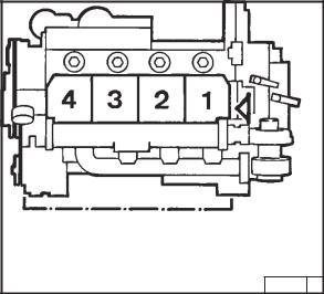
|
2.1 Тип |
Описание двигателя |
||
|
2.1.4 Нумерация цилиндров |
2 |
||
26233 0
Цилиндры пронумерованы последвательно, начиная со стороны маховика.

|
Описание двигателя |
2.2 Изображения двигателя |
22.2.1 Сторона обслуживания 1012
1 Маслоналивная горловина (специальный вариант: между фильтрами)
2 Наливная горловина для охлаждающей жидкостти
3 Вентилятор системы охлаждения
4 Насос для подачи охлаждающей жидкости
5 Ременный шкив
6 Топливоподкачивающий насос
7 Подвеска двигателя
8 Сменный топливный фильтр
9 Сменный фильтр для смазочного масла
10 Масляный поддон
11 Указатель уровня масла
12 Масляный радиатор
13 Элемент для присоединения гидравлических насосов
14 Генератор
15 Трубопровод для слива просачивающегося топлива с клапаном для поддержания напора
16 Головка блока цилиндров
26234 1

|
2.2 Изображения двигателя |
Описание двигателя |
||||
|
2.2.2 Сторона стартера 1012 |
2 |
||||
|
17 |
Транспортное устройство |
||||
|
18 |
Турбокомпрессор, работающий на ОГ |
||||
|
19 |
Регулятор частоты вращения |
||||
|
20 |
Корпус SAE |
||||
|
21 |
Маховик |
||||
|
22 |
Стартер |
||||
|
23 |
Охладитель рабочей жидкости гидросистемы |
||||
|
24 |
Теплообменник охлаждающей жидкости |
||||
|
25 |
Указатель уровня охлаждающей жидкости |
||||
|
26 |
Воздушный клапан |
26235 1
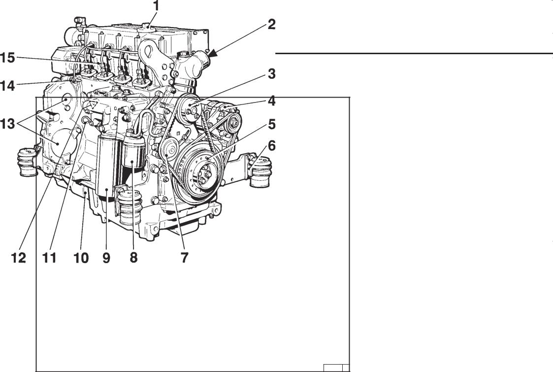
|
Описание двигателя |
2.2 Изображения двигателя |
22.2.3 Сторона обслуживания 1012 E
1 Маслоналивная горловина (специальный вариант: между фильтрами)
2 Соединительный элемент для охлаждающей жидкостти
3 Насос для подачи охлаждающей жидкости
4 Генератор
5 Ременный шкив
6 Подвеска двигателя
7 Топливоподкачивающий насос
8 Сменный топливный фильтр
9 Сменный фильтр для смазочного масла
10 Масляный поддон
11 Указатель уровня масла
12 Масляный радиатор
13 Элемент для присоединения гидравлического насоса
14 Трубопровод для слива просачивающегося топлива с клапаном для поддержания напора
15 Головка блока цилиндров
26236 1
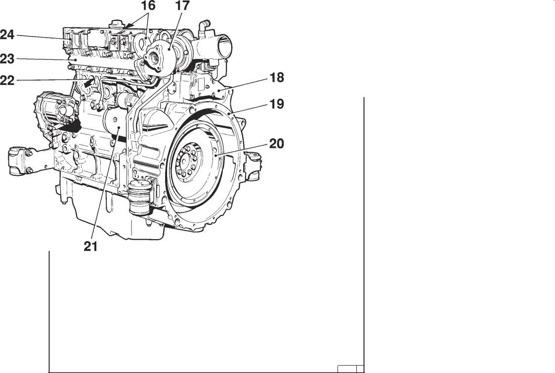
|
2.2 Изображения двигателя |
Описание двигателя |
||||
|
2.2.4 Сторона стартера 1012 E |
2 |
||||
|
16 |
Транспортное устройство |
||||
|
17 |
Турбокомпрессор, работающий на ОГ |
||||
|
18 |
Регулятор частоты вращения |
||||
|
19 |
Корпус SAE |
||||
|
20 |
Маховик |
||||
|
21 |
Стартер |
||||
|
22 |
Выход охлаждающей жидкости к |
||||
|
теплообменнику |
|||||
|
23 |
Выпускной коллектор |
||||
|
24 |
Впускная труба |
26237 0

|
Описание двигателя |
2.2 Изображения двигателя |
22.2.5 Сторона обслуживания 1013
1 Маслоналивная горловина (специальный вариант: между фильтрами)
2 Генератор
3 Насос для подачи охлаждающей жидкости
4 Вентилятор
5 Ременный шкив
6 Демпфер
7 Топливоподкачивающий насос
8 Подвеска двигателя
9 Сменный топливный фильтр
10 Сменный фильтр для смазочного масла
11 Масляный поддон
12 Указатель уровня масла
13 Масляный радиатор
14 Гидравлические насосы (или пристройка компрессора)
15 Топливопровод
16 Подъемный электромагнит
17 Смазочная линия к турбонагнетателю
18 Головка блока цилиндров
26 333 0

|
2.2 Изображения двигателя |
Описание двигателя |
||||
|
2.2.6 Сторона стартера 1013 |
2 |
||||
|
19 |
Транспортное устройство |
||||
|
20 |
Турбокомпрессор, работающий на ОГ |
||||
|
21 |
Регулятор частоты вращения |
||||
|
22 |
Корпус SAE |
||||
|
23 |
Маховик |
||||
|
24 |
Стартер |
||||
|
25 |
Указатель уровня охлаждающей жидкости |
||||
|
26 |
Воздушный клапан |
||||
|
27 |
Колпачок для охлаждающей жидкости |
26 334 0
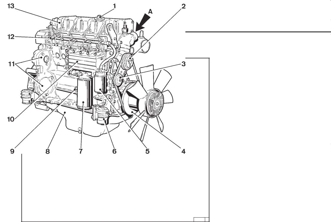
|
Описание двигателя |
2.2 Изображения двигателя |
22.2.7 Сторона обслуживания 1013 E
1 Маслоналивная горловина
2 Насос для подачи охлаждающей жидкости
3 Топливоподкачивающий насос
4 Демпфер
5 Сменный фильтр для смазочного масла
6 Подвеска двигателя
7 Сменный топливный фильтр
8 Масляный поддон
9 Указатель уровня масла
10 Масляный радиатор
11 Элемент для присоединения гидравлического насоса
12 Трубопровод для слива просачивающегося топлива с клапаном для поддержания напора
13 Головка блока цилиндров А Подводящая линия охлаждающей жидкости
26 336 0
![]()
|
2.2 Изображения двигателя |
Описание двигателя |
||||
|
2.2.8 Сторона стартера 1013 E |
2 |
||||
|
14 |
Транспортное устройство |
||||
|
15 |
Воздушный клапан картера |
||||
|
16 |
Регулятор частоты вращения |
||||
|
17 |
Корпус SAE |
||||
|
18 |
Маховик |
||||
|
19 |
Стартер |
||||
|
20 |
Турбокомпрессор, работающий на ОГ |
||||
|
21 |
Вентилятор |
||||
|
22 |
Выпускной коллектор |
||||
|
23 |
Впускная труба |
26 337 0
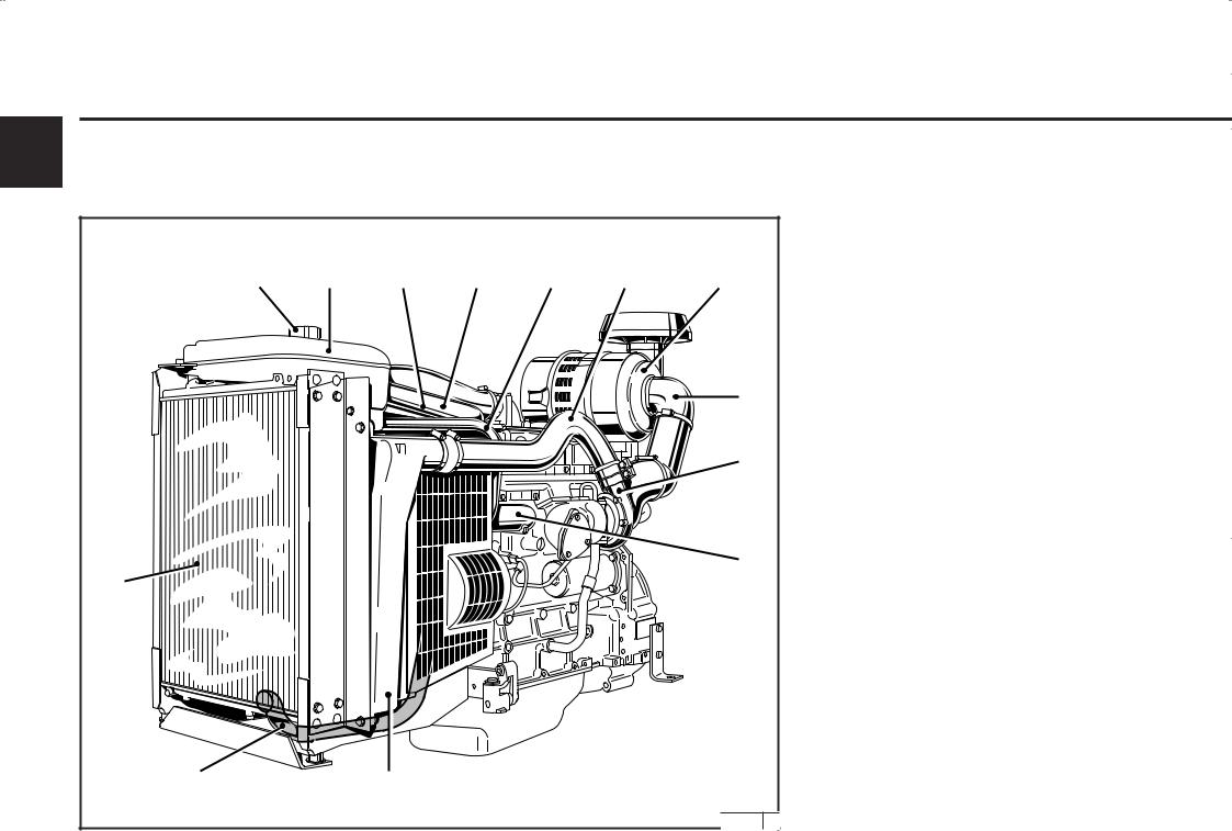
|
Описание двигателя |
2.2 Изображения двигателя |
|||||||||||
|
2 |
2.2.9 |
Сторона стартера |
||||||||||
|
Агрегатный двигатель |
||||||||||||
|
BF4M 1013 EC |
||||||||||||
|
1 |
Наливной патрубок для охлаждающей |
|||||||||||
|
жидкости с крышкой |
||||||||||||
|
1 |
2 |
3 |
4 |
5 |
6 |
7 |
2 |
Компенсационный бак (КБ) |
||||
|
3 |
Вентиляционная линия от блока головки |
|||||||||||
|
цилиндров к компенсационному баку |
||||||||||||
|
4 |
Трубопровод для охлаждающей жидкости от |
|||||||||||
|
картера двигателя к радиатору системы |
||||||||||||
|
жидкостного охлаждения двигателя |
||||||||||||
|
5 |
Уравнительный трубопровод от |
|||||||||||
|
8 |
компенсационного бака (КБ) к радиатору |
|||||||||||
|
6 |
Трубопровод для наддувочного воздуха от |
|||||||||||
|
турбокомпрессора, работающего на ОГ, к |
||||||||||||
|
охладителю наддувочного воздуха (ОНВ) |
||||||||||||
|
9 |
7 |
Воздухоочиститель с сухим фильтрующим |
||||||||||
|
элементом |
||||||||||||
|
8 |
Воздухопроводдлявпускаемоговоздухамежду |
|||||||||||
|
воздухоочистителем с сухим фильтрующим |
||||||||||||
|
элементом и турбокомпрессором, |
||||||||||||
|
10 |
работающим на ОГ |
|||||||||||
|
9 |
Турбокомпрессор, работающий на ОГ (ТКОГ) |
|||||||||||
|
12 |
10 |
Трубопровод для охлаждающей жидкости от |
||||||||||
|
картера к радиатору системы жидкостного |
||||||||||||
|
охлаждения двигателя |
||||||||||||
|
11 |
Охладитель наддувочного воздуха (ОНВ) |
|||||||||||
|
12 |
Радиатор системы жидкостного охлаждения |
|||||||||||
|
двигателя (РСЖОД) |
||||||||||||
|
13 |
Трубопровод для охлаждающей жидкости от |
|||||||||||
|
радиатора системы жидкостного охлаждения |
||||||||||||
|
двигателя к термостату двигателя |
||||||||||||
|
13 |
11 |
|||||||||||
|
2630 |
088336 |
0 |
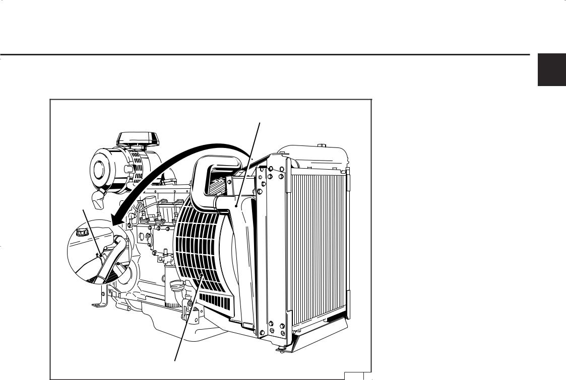
|
2.2 Изображения двигателя |
Описание двигателя |
|
|
2.2.10 Сторона обслуживания |
2 |
|
|
Агрегатный двигатель |
||
|
BF4M 1013 EC |
||
|
3 |
Вентиляционная линия от блока головки |
|
|
13 |
цилиндров к компенсационному баку |
|
|
13 |
Трубопровод для наддувочного воздуха от |
|
|
охладителя наддувочного воздуха к двигателю |
||
|
14 |
Защитная решетка |
|
|
3 |
||
|
14 |
||
|
3026 089337 |
0 |
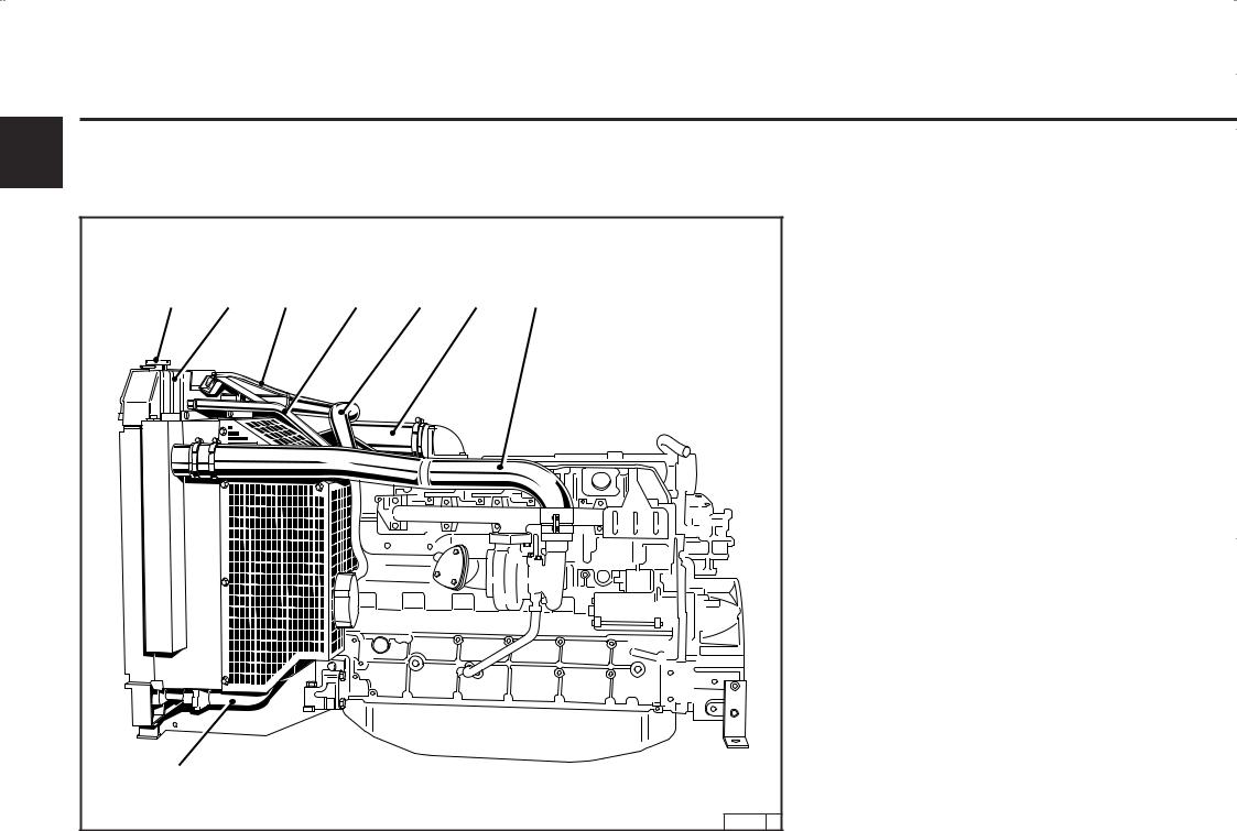
|
Описание двигателя |
2.2 Изображения двигателя |
||||||||
|
2 |
2.2.11 Сторона стартера |
||||||||
|
Агрегатный двигатель |
|||||||||
|
BF6M 1013 EC |
|||||||||
|
1 |
Наливной патрубок с крышкой |
||||||||
|
2 |
Компенсационный бак (КБ) |
||||||||
|
3 |
Вентиляционная линия от блока головки |
||||||||
|
1 |
2 |
3 |
4 |
5 |
6 |
7 |
цилиндров к компенсационному баку |
||
|
4 |
Уравнительный трубопровод от |
||||||||
|
компенсационного бака (КБ) к насосу для |
|||||||||
|
подачи охлаждающей жидкости |
|||||||||
|
5 |
Трубопровод для охлаждающей жидкости от |
||||||||
|
картера двигателя к радиатору системы |
|||||||||
|
жидкостного охлаждения двигателя |
|||||||||
|
6 |
Трубопровод для наддувочного воздуха от |
||||||||
|
охладителя наддувочного воздуха к двигателю |
|||||||||
|
7 |
Трубопровод для наддувочного воздуха от |
||||||||
|
турбокомпрессора, работающего на ОГ (ТКОГ), |
|||||||||
|
к охладителю наддувочного воздуха (ОНВ) |
|||||||||
|
8 |
Трубопровод для охлаждающей жидкости от |
||||||||
|
радиатора системы жидкостного охлаждения |
|||||||||
|
двигателя к термостату двигателя |
|||||||||
|
8 |
|||||||||
|
30 087 |
0 |

|
2.2 Изображения двигателя |
Описание двигателя |
||
|
2.2.12 Сторона обслуживания |
2 |
||
|
Агрегатный двигатель |
|||
|
BF6M 1013 EC |
|||
|
9 |
Радиатор системы жидкостного охлаждения |
||
|
двигателя (РСЖОД) |
|||
|
10 |
Охладитель наддувочного воздуха (ОНВ) |
||
|
11 |
Защитная решетка |
||
|
9 |
|||
|
11 |
10 |
||
|
30 086 |
0 |

|
Описание двигателя |
2.3 Циркуляция масла |
|||
|
2 |
2.3.1 |
Схема циркуляции |
||
|
смазочного масла |
||||
|
1012 / 1012 E |
||||
|
1 |
Масляный поддон |
|||||
|
2 |
Впускной газопровод |
|||||
|
3 |
Масляный насос |
|||||
|
3a |
Перепускной клапан |
|||||
|
3b |
Разгрузочный клапан |
|||||
|
4 |
Масляный радиатор |
|||||
|
5 |
Сменный фильтр для смазочного масла |
|||||
|
6 |
Магистральная масляная труба |
|||||
|
7 |
Коренной подшипник коленчатого вала |
|||||
|
8 |
Шатунный подшипник |
|||||
|
9 |
Подшипник распределительного вала |
|||||
|
10 |
Линия, ведущая к жиклеру |
|||||
|
11 |
Жиклер для охлаждения поршня |
|||||
|
12 |
Толкатель с импульсной смазкой коромысел |
|||||
|
13 |
Штанга толкателя, подача масла для смазки |
|||||
|
коромысел |
||||||
|
14 |
Коромысло |
|||||
|
15 |
Сливная линия к масляному поддону |
|||||
|
16 |
Датчик давления масла |
|||||
|
17 |
Смазочная линия, ведущая к |
|||||
|
турбокомпрессору, работающему на |
||||||
|
отработавших газах |
||||||
|
18 |
Турбокомпрессор, работающий на |
|||||
|
отработавших газах |
||||||
|
19 |
Смазочная линия, ведущая к компрессору или |
|||||
|
гидравлическому насосу |
||||||
|
20 |
Компрессор |
|||||
|
21 |
Гидравлический насос |
|||||
|
22 |
Сливная линия от компрессора или |
|||||
|
гидравлического насоса |
||||||
|
23 |
Линия к коробке передач для уравновешивания |
|||||
|
масс (2x) |
||||||
|
24 |
Валы для уравновешивания масс |
|||||
|
25 |
Сливная линия от турбокомпрессора, |
|||||
|
работающего на ОГ, к картеру |
||||||
|
26238 |
1 |

|
2.3 Циркуляция масла |
Описание двигателя |
2.3.2Схема циркуляции смазочного масла 1013 / 1013 E
2
1 Масляный поддон
2 Впускной газопровод
3 Масляный насос
3a Перепускной клапан
3b Разгрузочный клапан
4 Масляный радиатор
5 Сменный фильтр для смазочного масла
6 Магистральная масляная труба
7 Коренной подшипник коленчатого вала
8 Шатунный подшипник
9 Подшипник распределительного вала
10Линия, ведущая к жиклеру
11Жиклер для охлаждения поршня
12Толкатель с импульсной смазкой коромысел
13Штанга толкателя, подача масла для смазки коромысел
14Коромысло
15Сливная линия к масляному поддону
16Датчик давления масла
17Смазочная линия, ведущая к турбокомпрессору, работающему на отработавших газах
18Турбокомпрессор, работающий на отработавших газах
19Смазочная линия, ведущая к компрессору или гидравлическому насосу
20Компрессор
21Гидравлический насос
22Сливная линия от компрессора или гидравлического насоса
23Сливная линия к масляному поддону
24Сливная линия от турбокомпрессора, работающего на ОГ, к картеру
26 335 0

|
Описание двигателя |
2.4 Циркуляция топлива |
22.4.1 Схема циркуляции топлива
1 Топливный бак
2 Топливопровод к топливоподкачивающему насосу
3 Топливоподкачивающий насос
4 Топливопровод к топливному фильтру
5 Топливный фильтр
6 Топливопровод к топливным насосам высокого давления
7 Топливный насос высокого давления
8 Топливопровод к клапанной форсунке
9 Клапанная форсунка
10 Трубопровод для слива просачивающегося топлива
11 Полый винт с клапаном для поддержания напора
12 Сливная линия к топливному баку
13 Соблюдать максимальное возможное расстояние
26239 1

|
2.5 Циркуляция охлаждающей жидкости |
Описание двигателя |
||||
|
2.5.1 Схема циркуляции |
2 |
||||
|
охлаждающей жидкости 1012 |
|||||
|
1 |
Наливная горловина для охлаждающей |
||||
|
жидкости |
|||||
|
2 |
Корпус термостата |
||||
|
3 |
Насос для подачи охлаждающей жидкости |
||||
|
4 |
Масляный радиатор |
||||
|
5 |
Охлаждение цилиндров |
||||
|
6 |
Охлаждение головки блока цилиндров |
||||
|
7 |
Теплообменник |
||||
|
8 |
Сливная линия от насоса для подачи |
||||
|
охлаждающей жидкости к теплообменнику |
|||||
|
9 |
Вентиляционная линия от блока головки |
||||
|
цилиндров к теплообменнику |
|||||
|
(компенсационный бак) |
26240 2
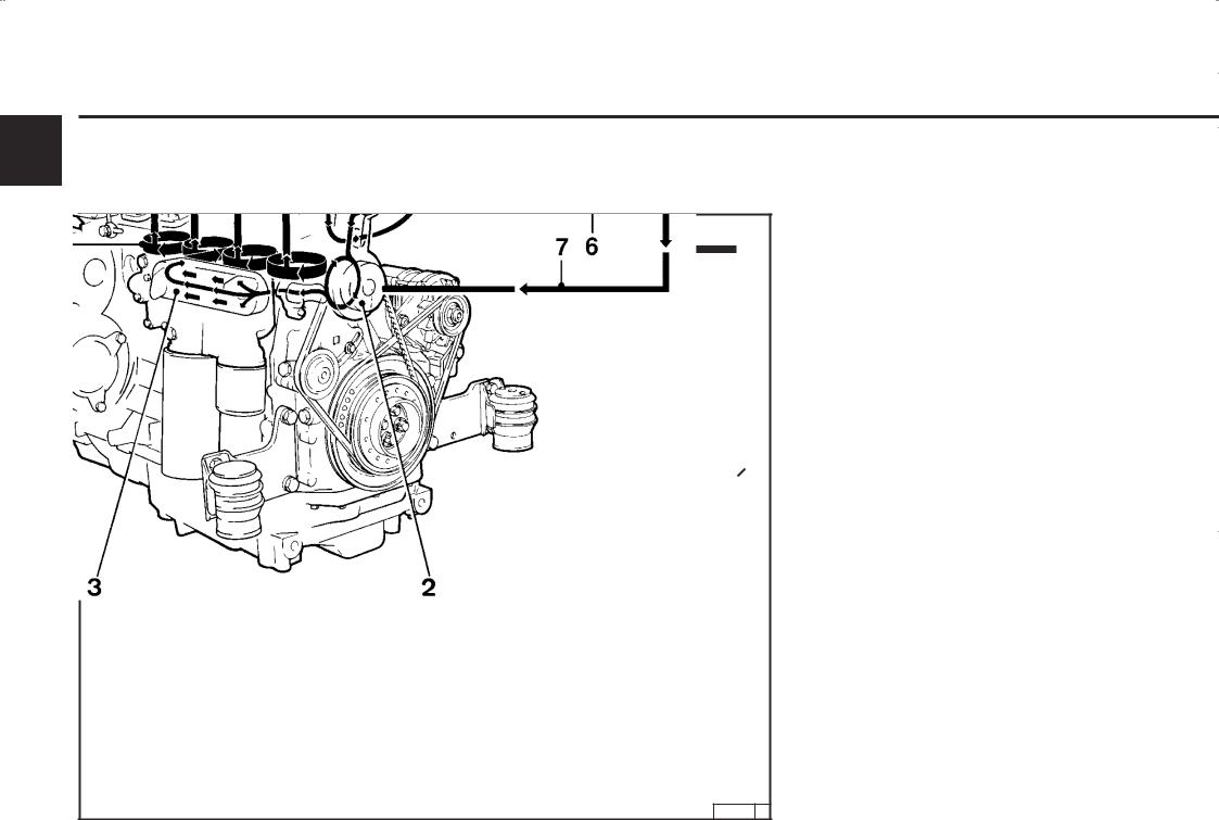
|
Описание двигателя |
2.5 Циркуляция охлаждающей жидкости |
22.5.2 Схема циркуляции охлаждающей жидкости 1012 E
1 Корпус термостата
2 Насос для подачи охлаждающей жидкости
3 Масляный радиатор
4 Охлаждение цилиндров
5 Охлаждение головки блока цилиндров
6 Теплообменник
7 Вентиляционная линия от компенсационного бака к насосу для подачи охлаждающей жидкости
8 Линия, ведущая от двигателя к теплообменнику
9 Вентиляционная линия от блока головки цилиндров к компенсационному баку
10 Компенсационный бак
11 Линия, ведущая от теплообменника к термостату
26 241 4
![]()
|
Описание двигателя |
2.5 Циркуляция охлаждающей жидкости |
|
1012Е |
2 |
|||
|
Ре“улирование выхода |
||||
|
1 |
Корпус термостата |
|||
|
2 |
Насос для подачи охлаждающей жидкости |
|||
|
3 |
Масляный радиатор |
|||
|
4 |
Охлаждение цилиндров |
|||
|
5 |
Охлаждение “оловки блока цилиндров |
|||
|
6 |
Теплообменник |
|||
|
7 |
Уравнительный трубопровод от |
|||
|
компенсационно“о бачка к насосу для подачи |
||||
|
охлаждающей жидкости |
||||
|
8 |
Трубопровод (Воздушный) от термостата к |
|||
|
теплообменнику |
||||
|
9 |
Трубопровод для удаления воздуха от “оловки |
|||
|
блока цилиндров к компенсационному бачку |
||||
|
10 |
Компенсационный бачок |
|||
|
11 |
Трубопровод от теплообменника к насосу для |
|||
|
подачи охлаждающей жидкости |
30 816 0

|
Описание двигателя |
2.5 Циркуляция охлаждающей жидкости |
|
2 |
|||
|
2.5.3 |
Схема циркуляции |
||
|
охлаждающей жидкости 1013 |
|||
1 Наливная горловина для охлаждающей жидкости
2 Корпус термостата
3 Насос для подачи охлаждающей жидкости
4 Масляный радиатор
5 Охлаждение цилиндров
6 Охлаждение головки блока цилиндров
7 Теплообменник
8 Уравнительный трубопровод между насосом для подачи охлаждающей жидкости и теплообменником
9 Вентиляционная линия от блока головки цилиндров к теплообменнику (компенсационный бак)
26 338 1

|
2.5 Циркуляция охлаждающей жидкости |
Описание двигателя |
|||||||
|
2.5.4 Схема циркуляции охлаждающей жидкости 1013 E |
2 |
|||||||
|
1 |
Корпус термостата |
|||||||
|
2 |
Насос для подачи охлаждающей жидкости |
|||||||
|
3 |
Масляный радиатор |
|||||||
|
4 |
Охлаждение цилиндров |
|||||||
|
5 |
Охлаждение головки блока цилиндров |
|||||||
|
6 |
Теплообменник |
|||||||
|
7 |
Вентиляционная линия от компенсационного |
|||||||
|
бака к насосу для подачи охлаждающей |
||||||||
|
жидкости |
||||||||
|
8 |
Линия, ведущая от двигателя к теплообменнику |
|||||||
|
9 |
Вентиляционная линия от блока головки |
|||||||
|
цилиндров к компенсационному баку |
||||||||
|
10 |
Компенсационный бак |
|||||||
|
11 |
Линия, ведущая от теплообменника к |
|||||||
|
термостату |
||||||||

|
Описание двигателя |
2.5 Циркуляция охлаждающей жидкости |
|
2 |
1013Е |
|
|
Ре“улирование выхода |
||
1 Корпус термостата
2 Насос для подачи охлаждающей жидкости
3 Масляный радиатор
4 Охлаждение цилиндров
5 Охлаждение “оловки блока цилиндров
6 Теплообменник
7 Уравнительный трубопровод от компенсационно“о бачка к насосу для подачи охлаждающей жидкости
8 Трубопровод (Воздушный) от термостата к теплообменнику
9 Трубопровод для удаления воздуха от “оловки блока цилиндров к компенсационному бачку
10 Компенсационный бачок
11 Трубопровод от теплообменника к насосу для подачи охлаждающей жидкости
30 817 0

Обслуживание
3
3.1Первый ввод в эксплуатацию
3.2Пуск
3.3Контроль работы двигателя
3.4Выключение
3.5Условия эксплуатации
 Loading…