- Manuals
- Brands
- Mitsubishi Manuals
- Controller
- FX2N series
Manuals and User Guides for Mitsubishi FX2N series. We have 3 Mitsubishi FX2N series manuals available for free PDF download: User Manual, Programming Manual, Hardware Manual
Mitsubishi FX2N series User Manual (520 pages)
FX3U series programmable controllers
Brand: Mitsubishi
|
Category: Controller
|
Size: 14.44 MB
Table of Contents
-
Safety Precautions
9
-
Table of Contents
11
-
Standards
23
-
Certification of UL, Cul Standards
23
-
Compliance with EC Directive (CE Marking)
24
-
Requirement for Compliance with EMC Directive
24
-
Requirement for Compliance with LVD Directive
27
-
Caution for Compliance with EC Directive
28
-
-
-
-
1 Introduction
29
-
Introduction of Manuals
29
-
Classification of Major Components in this Manual
29
-
Manual Organization and Position of this Manual
31
-
List of Manuals
32
-
-
Generic Names and Abbreviations Used in Manuals
39
-
-
2 Features and Part Names
42
-
Major Features
42
-
Names and Functions of Parts
44
-
Front Panel
44
-
Sides
46
-
-
-
3 Introduction of Products (Compliant with Overseas Standards)
47
-
List of Products (to be Connected) and Interpretation of Model Names
47
-
A] Main Units
48
-
B] Input/Output Powered Extension Units
49
-
C] Input/Output Extension Blocks
50
-
D] [E] Special Function Units/Blocks
51
-
F] Display Modules and Holder
53
-
G] Expansion Boards
53
-
H] Special Adapters
54
-
I] Extension Power Supply Unit
55
-
J] Extension Cables and Connector Conversion Adapter [K] Battery [L] Memory Cassettes
55
-
M] FX Series Terminal Blocks (Cables and Connectors)
56
-
N] Remote I/O
56
-
O] Power Supply Unit
56
-
-
Connector Types and Cables for Program Communication
57
-
Programming Tool
58
-
Communication Cables
58
-
Converters and Interface
59
-
-
-
4 Specifications, External Dimensions and Terminal Layout (Main Units)
60
-
Generic Specifications
60
-
Dielectric Withstand Voltage Test and Insulation Resistance Test
61
-
-
Power Supply Specifications
62
-
AC Power Supply/DC Input Type
62
-
DC Power Supply/DC Input Type
63
-
AC Power Supply/Ac Input Type
63
-
-
Input Specifications
64
-
DC Input (Sink/Source) Type
64
-
AC Input Type
65
-
-
Output Specifications
66
-
Relay Output Type
66
-
Product Life of Relay Contacts
67
-
Transistor Output (Sink) Type
68
-
Transistor Output (Source) Type
69
-
Triac Output Type
70
-
-
Performance Specifications
71
-
External Dimensions (Weight and Installation)
74
-
Fx -16M , Fx
74
-
Fx 3U -48M , Fx 3U -64M , Fx 3U -80M , Fx 3U -128M
75
-
-
Terminal Layout
76
-
Interpretation
76
-
Fx 3U -16M
77
-
Fx 3U -32M
78
-
Fx 3U -48M
79
-
Fx 3U -64M
80
-
Fx 3U -80M
81
-
Fx 3U -128M
82
-
-
-
5 Version Information and Peripheral Equipment Connectability
83
-
Version Upgrade History
83
-
How to Look at Manufacturer’s Serial Number
83
-
Version Check Method
84
-
Version Upgrade History
84
-
-
Programming Tool Applicability
85
-
Applicable Versions of Programming Tool
85
-
In Case of Programming Tool (Version) Not Applicable
86
-
Program Transfer Speed and Programming Tools
86
-
Cautions on Connecting Peripheral Equipment by Way of Expansion Board or Special Adapter
87
-
Cautions on Write During RUN
88
-
-
Cautions on Using Transparent Function by Way of USB in GOT1000 Series
92
-
Cautions on Using Transparent Port (2-Port) Function of GOT-F900 Series
93
-
Other Peripheral Equipment Applicability
94
-
-
6 Examination of System Configuration
95
-
Configuration of a Whole System
95
-
List of System Components
96
-
System Configuration with Special Adapters
98
-
-
Rules of System Configuration
99
-
Number of Input/Output Points and Maximum Number of Input/Output Points
101
-
Calculation of Number of Input/Output Points
101
-
Maximum Number of Input/Output Points When CC-Link Master Is Used
103
-
Maximum Number of Input/Output Points When AS-I Master Is Used
104
-
-
Number of Connected Special Extension Devices (Including Extension Cable)
105
-
Expansion Board and Special Adapter
105
-
Special Function Units/Blocks, High-Speed Input/Output Special Adapter
105
-
Extension Cable
105
-
-
Expansion of Main Unit (Calculation of Current Consumption)
106
-
Quick Reference Matrix — When Only Input/Output Devices Are Added (AC Power Supply/DC Input Type)
106
-
When Special Extension Devices Are also Added [Calculation of Current Consumption] (AC Power Supply/DC Input Type)
108
-
Quick Reference Matrix [When Only Input/Output Devices Are Added] (DC Power Type)
111
-
When Special Extension Devices Are also Added [Calculation of Current Consumption] (DC Power Type)
112
-
Quick Reference Matrix [When Only Input/Output Devices Are Added] (AC Power Supply/Ac Input Type)
115
-
(AC Power Supply/Ac Input Type)
116
-
-
-
Expansion of FX 2N Series I/O Powered Extension Unit (Calculation of Current Consumption)
119
-
Quick Reference Matrix (When Only Input/Output Devices Are Added)
119
-
When Special Extension Devices Are also Added (Calculation of Current Consumption)
122
-
-
Expansion of Extension Power Supply Unit (FX 3U -1PSU-5V)
124
-
Number of Input/Output (Occupied) Points and Current Consumption
127
-
A] Main Units
128
-
B] Expansion Boards
130
-
C] Special Adapters
130
-
D] Input/Output Powered Extension Units/Blocks
131
-
E] Special Extension Devices
132
-
G] Display Module
133
-
H] Extension Power Supply Unit
133
-
-
Example of System Configuration and System Modification
134
-
Example System Configuration
134
-
Expansion of Main Unit
135
-
Re-Examination of Suitability for Configuration
138
-
-
-
7 Assignment of Input/Output Numbers (X/Y) and Unit Numbers
143
-
Assignment of Input/Output Numbers (X/Y)
143
-
Concept of Assigning
143
-
Example of Assigning
144
-
Application of I/O Number Label
145
-
-
Unit Numbers of Special Function Units/Blocks
146
-
Concept of Assigning
146
-
Example of Assigning
147
-
Application of Unit Number Labels
148
-
-
Application of the Trimmer Layout Label
148
-
-
8 Installation in Enclosure
149
-
Generic Specifications
152
-
Installation Location
153
-
Installation Location in Enclosure
153
-
Spaces in Enclosure
154
-
-
Layout in Enclosure
155
-
1-Stage Layout
155
-
-
Examination for Installing Method in Enclosure
157
-
Installing Methods
157
-
Cautions on Examining Installing Method
157
-
Examples of Installation
157
-
-
Procedures for Installing on and Detaching from DIN Rail
159
-
Preparation for Installation
159
-
Installation of Main Unit
160
-
Installation of Input/Output Powered Extension Unit/Block and Special Function Unit/Block
161
-
Removal of Main Unit
161
-
-
Procedures for Installing Directly (with M4 Screws)
163
-
Hole Pitches for Direct Mounting
163
-
Example of Mounting Hole Pitches
166
-
Installation of Main Unit
167
-
Installation of Input/Output Powered Extension Unit/Block and Special Function Unit/Block
167
-
-
Connecting Methods for Main Unit and Extension Devices
168
-
Connection of Extension Devices
168
-
Connecting Method a — Connection of Expansion Board
169
-
Connecting Method B — Connection of Special Adapter
170
-
Connecting Method C — Connection of Powered Extension Unit/Block to Main Unit
170
-
Connecting Method D — Connection of Powered Extension Units/Blocks
171
-
Connecting Method E — Connection of Extension Cable and FX 2N -CNV-BC
172
-
Connecting Method F — Connection of Input/Output Powered Extension Unit
172
-
Connecting Method G — Connection of Extension Block to Input/Output Powered Extension Unit
173
-
-
-
9 Preparation for Wiring and Power Supply Wiring Procedures
174
-
Preparation for Wiring
176
-
Wiring Procedures
176
-
Removal and Installation of Quick-Release Terminal Block (Except for the FX 3U -16M )
176
-
-
Cable Connecting Procedures
177
-
Input/Output Terminal Block (Power Supply and Input/Output Wiring)
177
-
Input/Output Connectors
180
-
Terminal Block (for Europe) [Expansion Board and Special Adapters]
181
-
-
Power Supply Specifications
183
-
AC Power Supply Type
183
-
DC Power Supply Type
184
-
-
Grounding
185
-
Examples of External Wiring [AC Power Supply/DC Input Type]
186
-
Example of Input/Output Wiring with 24V DC Service Power Supply
186
-
Example of Sink Input [-Common] Wiring
187
-
Example of Source Input [+Common] Wiring
188
-
An External Wiring Example for the Extension Power Supply Unit (Sink Input [-Common])
189
-
An External Wiring Example for the Extension Power Supply Unit (Source Input [+Common])
190
-
-
Examples of External Wiring [DC Power Supply/DC Input Type]
191
-
Example of Sink Input [-Common] Wiring
191
-
Example of Source Input [+Common] Wiring
192
-
-
Examples of External Wiring [AC Power Supply/Ac Input Type]
193
-
Example of AC Input Wiring
193
-
-
-
10 Input Wiring Procedures (Input Interruption and Pulse Catch)
194
-
Before Starting Input Wiring
196
-
Sink and Source Input (24V DC Input Type)
196
-
-
DC Input Type (Common to Sink/Source Input)
197
-
Input Specifications (Main Unit)
197
-
Handling of 24V DC Input
198
-
Instructions for Connecting Input Devices
199
-
Examples of External Wiring (Sink Input) [AC Power Supply Type]
201
-
Example of External Wiring (Source Input) [AC Power Supply Type]
203
-
Examples of External Wiring (Sink Input) [DC Power Supply Type]
204
-
Example of External Wiring (Source Input) [DC Power Supply Type]
206
-
-
AC Input Type
207
-
Input Specifications (Main Unit)
207
-
Handling of 100V AC Input
208
-
Example of External Wiring
209
-
Input Interruption
210
-
-
To I50 ) — with Delay Function
210
-
Allocation of Pointers to Input Numbers (Input Signal ON/OFF Duration)
210
-
Input Interruption Delay Function
210
-
Cautions for Input Interruption
210
-
Examples of External Wiring
211
-
-
Pulse Catch (M8170 to M8177)
212
-
Allocation of Special Memories to Input Numbers (on Duration of Input Signals)
212
-
Cautions for Pulse Catch
212
-
Examples of External Wiring
213
-
-
-
11 Use of High-Speed Counters (C235 to C255)
214
-
Outline
214
-
Input Specifications
215
-
High-Speed Input Special Adapter (FX 3U -4HSX-ADP)
215
-
Cautions on Connecting Mating Device
215
-
-
Types of Counting and Operations
216
-
Classification According to Counting Method
216
-
Types and Input Signal Forms
216
-
High-Speed Counter Device Notations
216
-
-
List of Device Numbers and Functions
217
-
Allocation of Device Numbers to Input Numbers
219
-
Allocation Table
219
-
Inhibition of Redundant Use of Input Numbers
220
-
-
Handling of High-Speed Counters
221
-
1-Phase 1-Count Input
221
-
1-Phase 2-Count Input
222
-
2-Phase 2-Count Input
223
-
-
Timing of Updating of Current Value and Comparison of Current Value
224
-
Timing of Updating of Current Value
224
-
Comparison of Current Value
224
-
-
Conditions for Hardware Counter to be Handled as Software Counter
225
-
Conditions under Which Counters Are Handled as Software Counters
225
-
Method of Confirming Operation Status of Counters
225
-
-
Calculation of Response Frequency and Overall Frequency
226
-
Response Frequencies of Hardware Counters
226
-
Response Frequencies and Overall Frequency of Software Counters
226
-
-
Examples of External Wiring (Rotary Encoder)
229
-
1-Phase 1-Input [C235 to C245]
229
-
2-Phase 2-Input [C251 to C255]
230
-
Cautions for the Other Side Device
231
-
-
Related Devices and Function Switching Procedures
232
-
Related Devices
232
-
Function Switching] Switching of Logic of External Reset Input Signal
234
-
Function Switching] Switching of Allocation and Functions of Input Terminals
234
-
Function Switching] Procedures for Using 2-Phase 2-Count Input Counters C251 to C255 in 4 Edge Count Mode
235
-
-
Cautions on Use
236
-
-
12 Output Wiring Procedures
237
-
Sink and Source Output (Transistor)
239
-
External Wiring for Relay Output
240
-
Output Specifications (Main Unit) Relay Output
240
-
Product Life of Relay Contacts
241
-
Handling of Relay Output
241
-
External Wiring Precautions
242
-
Example of External Wiring
243
-
-
External Wiring of Transistor Output (Sink/Source) Type
244
-
Output Specifications (Main Unit) Transistor Output (Sink) Type
245
-
Output Specifications (Main Unit) Transistor Output (Source) Type
246
-
Handling of Transistor Output
247
-
External Wiring Precautions
249
-
Example of External Wiring
251
-
-
External Wiring for Triac (SSR) Output Type
253
-
Output Specification (Main Unit) Triac Output Type
253
-
Handling of Triac Output
254
-
External Wiring Precautions
255
-
Example of External Wiring
256
-
-
-
13 Examples of Wiring for Various Uses
257
-
Notes about Examples of Wiring
258
-
Digital Switch [DSW Instruction (FNC 72)/BIN Instruction (FNC 19)]
259
-
When DSW Instructions Are Used
259
-
When bin Instructions Are Used
262
-
-
Ten Key Input [TKY Instruction (FNC 70)]
263
-
Hexadecimal Input [HKY Instruction (FNC 71)]
264
-
Input Matrix [MTR Instruction (FNC 52)]
267
-
Seven Segment with Latch [SEGL Instruction (FNC 74)/BCD Instruction (FNC 18)]
270
-
When SEGL Instructions Are Used
270
-
When BCD Instructions Are Used
272
-
-
-
14 Test Operation, Adjustment, Maintenance and Troubleshooting
274
-
Preparation for Test Operation
275
-
Preliminary Inspection [Power OFF]
275
-
Connection to Built-In Programming Connector
275
-
Writing of Program and Program Check [Power on and PLC Stopped]
276
-
-
Running and Stopping Procedures [Power ON]
277
-
Methods of Running and Stopping
277
-
Use of Several Running/Stopping Methods
278
-
-
Operation and Test [Power on and PLC Running]
279
-
Self-Diagnostic Function
279
-
Test Functions
279
-
Program Modification Function
280
-
-
Maintenance and Periodic Inspection
281
-
Procedures for Checking Model Name
281
-
Periodic Inspection — Battery Life, Etc
281
-
Maintenance — Product Life of Relay Contacts
282
-
Procedures for Replacing Battery
283
-
-
Troubleshooting with Leds
284
-
POWER LED [On/Flashing/Off]
284
-
BATT LED [On/Off]
284
-
ERROR LED [On/Flashing/Off]
285
-
-
Judgment by Error Codes and Representation of Error Codes
286
-
Operation and Check on Display Module (FX 3U -7DM)
286
-
Operation and Check by GX Developer
287
-
Representation of Errors
288
-
Error Code List and Action
289
-
-
Troubleshooting
297
-
Output Does Not Operate (Main Unit and Input/Output Extension Blocks)
297
-
DC Input Does Not Operate (Main Unit and Input/Output Extension Blocks)
297
-
Cautions on Registering a Keyword
298
-
Cautions on Using Block Password
298
-
-
-
15 FX 2N -32/48E*-* (Input/Output Powered Extension Units)
299
-
Outline
301
-
Product Configuration
301
-
Product List
301
-
-
Power Supply Specifications (Power Supply Input/24V DC Service Power Supply)
302
-
Weight, Accessories, Etc
302
-
Part Names
303
-
-
Fx2N-32Er-Es/Ul, Fx2N-48Er-Es/Ul, Fx2N-48Er-Ds
305
-
Product Specifications
305
-
External Dimensions
306
-
Terminal Layout
307
-
-
Fx2N-32Et-Ess/Ul, Fx2N-48Et-Ess/Ul, Fx2N-48Et-Dss
308
-
Product Specifications
308
-
External Dimensions
309
-
Terminal Layout
310
-
-
Fx 2N -32Er, Fx 2N -48Er, Fx 2N -48Er-D
311
-
Product Specifications
311
-
External Dimensions
312
-
Terminal Layout
313
-
-
Fx 2N -32Et, Fx 2N -48Et, Fx 2N -48Et-D
314
-
Product Specifications
314
-
External Dimensions
315
-
Terminal Layout
316
-
-
Fx 2N -32Es
317
-
Product Specifications
317
-
External Dimensions
318
-
Terminal Layout
318
-
-
Fx 2N -48Er-Ua1/Ul
319
-
Product Specifications
319
-
External Dimensions
320
-
Terminal Layout
321
-
-
-
16 FX 2N -8/16E*-*(Input/Output Extension Blocks)
322
-
Outline
323
-
Product Type
323
-
List of Products
324
-
Fx 2N
326
-
-
-
FX -8ER-ES/UL (24V DC Sink/Source Input, Relay Output)
326
-
Product Specifications
326
-
Parts Identification and Terminal Arrangement
327
-
External Dimensions
328
-
-
FX 2N -8ER (24V DC Sink Input, Relay Output)
329
-
Product Specifications
329
-
Parts Identification and Terminal Arrangement
330
-
External Dimensions
331
-
-
Fx 2N -8Ex-Es/Ul, Fx 2N
332
-
16EX-ES/UL (24V DC Sink/Source Input)
332
-
Product Specifications
332
-
Parts Identification and Terminal Arrangement
333
-
External Dimensions
334
-
FX 2N -8EX, FX 2N -16EX and FX 2N -16EX-C
335
-
-
-
FX -8EX, FX -16EX and FX -16EX-C
335
-
Product Specifications
335
-
Parts Identification and Terminal Arrangement
336
-
External Dimensions
337
-
-
FX 2N -16EXL-C (5V DC Input: 16 Points)
339
-
Product Specifications
339
-
Parts Identification and Terminal Arrangement
340
-
External Dimensions
340
-
Example of Wiring
340
-
Fx 2N
342
-
-
-
FX -8EX-UA1/UL (100V AC Input)
342
-
Product Specifications
342
-
Parts Identification and Terminal Arrangement
343
-
External Dimensions
343
-
-
8Eyr-Es/Ul, Fx
344
-
8Eyr-S-Es/Ul, Fx
344
-
16EYR-ES/UL (Relay Output)
344
-
Product Specifications
344
-
FX 2N -8EYR-ES/UL, FX 2N -8EYR-S-ES/UL, FX 2N -16EYR-ES/UL (Relay Output)
344
-
Parts Identification and Terminal Arrangement
345
-
External Dimensions
347
-
-
Fx 2N -8Eyt-Ess/Ul, Fx 2N
348
-
16EYT-ESS/UL (Transistor Output)
348
-
Product Specifications
348
-
Parts Identification and Terminal Arrangement
349
-
External Dimensions
350
-
Fx 2N -8Eyr, Fx 2N
351
-
-
-
FX -8EYR, FX -16EYR (Relay Output)
351
-
Product Specifications
351
-
Parts Identification and Terminal Arrangement
352
-
External Dimensions
353
-
-
FX2N-8EYT, FX2N-16EYT and FX2N-16EYT-C (Transistor Output)
354
-
Product Specifications
354
-
Parts Identification and Terminal Arrangement
355
-
External Dimensions
356
-
-
FX -8EYT-H (Transistor Output)
358
-
Product Specifications
358
-
FX 2N -8EYT-H (Transistor Output)
358
-
Parts Identification and Terminal Arrangement
359
-
External Dimensions
359
-
-
FX -16EYS (Triac Output: 16 Points)
360
-
Product Specifications
360
-
FX 2N -16EYS (Triac Output: 16 Points)
360
-
Parts Identification and Terminal Arrangement
361
-
External Dimensions
361
-
-
-
17 FX 3U -1PSU-5V (Extension Power Supply Unit)
362
-
Introduction
362
-
Specifications
363
-
Generic Specifications
363
-
Performance Specifications
363
-
External Dimensions
363
-
-
Extension Power Supply Unit Related Precaution
363
-
-
18 Other Extension Devices and Optional Units (External Dimensions and Terminal Arrangement)
364
-
Special Function Units/Blocks
364
-
Fx 0N -3A
364
-
Fx 2N -2Ad
364
-
Fx 2N -2Da
365
-
Fx 3U -4Ad
365
-
Fx 3U -4Da
366
-
Fx 2N -4Ad
366
-
Fx 2N -4Da
367
-
Fx 2N -4Ad-Pt
367
-
Fx 2N -4Ad-Tc
368
-
Fx 2N -5A
368
-
Fx 3U -4Lc
369
-
Fx 2N -2Lc
369
-
Fx 2N -8Ad
370
-
Fx 3U -2Hc
370
-
Fx 2N -1Hc
371
-
Fx 3U -20Ssc-H
371
-
Fx 2N -1Pg(-E)
372
-
Fx 2N -10Pg
372
-
Fx 2N -10Gm
373
-
Fx 2N -20Gm
373
-
Fx -1Rm(-E)-Set
374
-
Fx 2N -232If
375
-
Fx 2N -32Asi-M
375
-
Fx 2N -64Cl-M
376
-
Fx 3U -16Ccl-M
376
-
Fx 2N -16Ccl-M
377
-
Fx 2N -32Ccl
377
-
Fx 3U -64Ccl
378
-
Fx 2N -16Lnk-M
378
-
-
Extension Power Supply Unit
379
-
Fx 3U -1Psu-5V
379
-
Special Adapters
379
-
Fx 3U -4Ad-Adp
379
-
Fx 3U -4Da-Adp
380
-
Fx 3U -3A-Adp
380
-
Fx 3U -4Ad-Pt(W)-Adp
380
-
Fx 3U -4Ad-Pnk-Adp
381
-
Fx 3U -4Ad-Tc-Adp
381
-
Fx 3U -232Adp(-Mb)
382
-
Fx 3U -485Adp(-Mb)
382
-
Fx 3U -Cf-Adp
383
-
Fx -4Hsx-Adp
383
-
Fx 3U -2Hsy-Adp
383
-
-
Expansion Board
384
-
Fx 3U -Usb-Bd
384
-
Fx 3U -232-Bd
384
-
Fx 3U -422-Bd
384
-
Fx 3U -485-Bd
385
-
Fx -8Av-Bd
385
-
Fx -Cnv-Bd
385
-
-
Power Supply
386
-
Fx 2N- 20Psu
386
-
-
Connector Conversion Adapter
386
-
Fx 2N -Cnv-Bc
386
-
-
Interface Module
387
-
Fx-232Awc-H
387
-
Fx-Usb-Aw
387
-
-
Display Module
388
-
Fx 3U -7Dm
388
-
Fx 3U -7Dm-Hld
388
-
-
Advertisement
Mitsubishi FX2N series Programming Manual (466 pages)
MELSEC-F
Brand: Mitsubishi
|
Category: Controller
|
Size: 6.84 MB
Table of Contents
-
Table of Contents
7
-
FX Series Programmable Controllers
3
-
Table of Contents
7
-
-
1 Introduction
15
-
Overview
17
-
What Do You Need to Program a PLC
18
-
What Is a Programmable Controller?
18
-
Special Considerations for Programming Equipment
19
-
Current Generation CPU All Versions
19
-
-
Associated Manuals
20
-
-
2 Basic Program Instructions
23
-
What Is a Program
25
-
Outline of Basic Devices Used in Programming
25
-
How to Read Ladder Logic
26
-
Load, Load Inverse
27
-
Out
28
-
Timer and Counter Variations
28
-
Double Coil Designation
29
-
-
And, and Inverse
30
-
Or, or Inverse
31
-
Load Pulse, Load Trailing Pulse
32
-
And Pulse, and Trailing Pulse
33
-
Or Pulse, or Trailing Pulse
34
-
Or Block
35
-
And Block
36
-
MPS, MRD and MPP
37
-
Master Control and Reset
39
-
Set and Reset
41
-
Timer, Counter (out & Reset)
42
-
Basic Timers, Retentive Timers and Counters
42
-
High Speed Counters
43
-
Normal 32 Bit Counters
43
-
-
Leading and Trailing Pulse
44
-
Inverse
45
-
No Operation
46
-
End
47
-
-
3 STL Programming
49
-
What Is STL, SFC and IEC1131 Part 3
51
-
Each Step Is a Program
52
-
-
How STL Operates
52
-
How to Start and End an STL Program
53
-
Activating New States
53
-
Embedded STL Programs
53
-
Terminating an STL Program
54
-
-
Moving between STL Steps
55
-
Using SET to Drive an STL Coil
55
-
Using out to Drive an STL Coil
56
-
-
Rules and Techniques for STL Programs
57
-
Basic Notes on the Behavior of STL Programs
57
-
Single Signal Step Control
59
-
-
Restrictions of some Instructions When Used with STL
60
-
Using STL to Select the most Appropriate Program
61
-
Using STL to Activate Multiple Flowssimultaneously
62
-
General Rules for Successful STL Branching
64
-
General Precautions When Usingfx-PCS/AT-EE Software
65
-
Programming Examples
66
-
A Simple STL Flow
66
-
A Selective Branch/ First State Merge Example Program
68
-
-
Advanced STL Use
70
-
-
4 Devices in Detail
71
-
Inputs
73
-
Outputs
74
-
Auxiliary Relays
75
-
Battery Backed/ Latched Auxiliary Relays
76
-
Special Diagnostic Auxiliary Relays
77
-
Special Single Operation Pulse Relays
77
-
-
State Relays
78
-
General Stable State — State Relays
78
-
Battery Backed/ Latched State Relays
79
-
STL Step Relays
80
-
Annunciator Flags
81
-
-
Pointers
82
-
Interrupt Pointers
83
-
Input Interrupts
84
-
Timer Interrupts
84
-
Counter Interrupts
85
-
Disabling Individual Interrupts
85
-
-
Constant K
86
-
Constant H
86
-
Timers
87
-
General Timer Operation
88
-
Selectable Timers
88
-
Retentive Timers
89
-
Timer Accuracy
90
-
Timers Used in Interrupt and ‘CALL’ Subroutines
90
-
-
Counters
91
-
General/ Latched 16Bit up Counters
92
-
General/ Latched 32Bit Bi-Directional Counters
93
-
High Speed Counters
94
-
Basic High Speed Counter Operation
95
-
Availability of High Speed Counters
96
-
Phase Counters — User Start and Reset (C235 — C240)
98
-
Phase Counters — Assigned Start and Reset (C241 to C245)
99
-
Phase Bi-Directional Counters (C246 to C250)
100
-
A/B Phase Counters (C252 to C255)
101
-
-
Data Registers
102
-
General Use Registers
103
-
Battery Backed/ Latched Registers
104
-
Special Diagnostic Registers
104
-
File Registers
105
-
Externally Adjusted Registers
106
-
-
Index Registers
107
-
Misuse of the Modifiers
108
-
Modifying a Constant
108
-
Using Multiple Index Registers
108
-
-
Bits, Words, BCD and Hexadecimal
109
-
Bit Devices, Individual and Grouped
109
-
Word Devices
109
-
Interpreting Word Data
111
-
Two’s Compliment
114
-
-
Floating Point and Scientific Notation
115
-
Scientific Notation
116
-
Floating Point Format
117
-
Summary of the Scientific Notation and Floating Point Numbers
118
-
-
-
5 Applied Instructions
119
-
Applied Instructions
121
-
Program Flow-Functions 00 to 09
124
-
Cj (Fnc 00)
125
-
Call (Fnc 01)
127
-
Sret (Fnc 02)
129
-
Iret, Ei, DI(Fnc 03, 04, 05)
130
-
Fend (Fnc 06)
132
-
Wdt (Fnc 07)
133
-
For, Next(Fnc 08, 09)
134
-
-
-
-
Pppp —
137
-
Move and Compare — Functions 10 to 19
137
-
Cmp (Fnc 10)
138
-
-
Cmp Fnc
138
-
Zcp (Fnc 11)
139
-
-
Zcp Fnc
139
-
Mov (Fnc 12)
140
-
Smov (Fnc 13)
141
-
-
Smov — Fnc
141
-
Cml (Fnc 14)
142
-
-
Cml Fnc
142
-
Bmov (Fnc 15)
143
-
-
Bmov Fnc
143
-
Fmov (Fnc 16)
144
-
-
Fmov Fnc
144
-
Xch (Fnc 17)
145
-
-
Xch Fnc
145
-
Bcd (Fnc18)
146
-
-
Bcd — Fnc
146
-
Bin (Fnc 19)
147
-
-
BIN — Binary FNC
147
-
Arithmetic and Logical Operations -Functions 20 to 29
149
-
Add (Fnc 20)
150
-
Sub (Fnc 21)
151
-
Mul (Fnc 22)
152
-
DIV (Fnc 23)
153
-
Inc (Fnc 24)
154
-
Dec (Fnc 24)
155
-
Wand (Fnc 26)
156
-
Wor (Fnc 27)
157
-
Wxor (Fnc 28)
158
-
Neg (Fnc 29)
159
-
-
Rotation and Shift — Functions 30 to 39
162
-
Ror (Fnc 30)
163
-
Rol (Fnc 31)
164
-
Rcr (Fnc 32)
165
-
Rcl (Fnc 33)
166
-
Sftr (Fnc 34)
167
-
Sftl (Fnc 35)
168
-
Wsfr (Fnc 36)
169
-
Wsfl (Fnc 37)
170
-
Sfwr (Fnc 38)
171
-
Sfrd (Fnc 39)
172
-
-
Data Operation — Functions 40 to 49
174
-
Zrst (Fnc 40)
175
-
Deco (Fnc 41)
176
-
Enco (Fnc 42)
177
-
Sum (Fnc 43)
178
-
Bon (Fnc 44)
179
-
Mean (Fnc 45)
180
-
Ans (Fnc 46)
181
-
Anr (Fnc 47)
182
-
Sqr (Fnc 48)
183
-
Flt (Fnc 49)
184
-
-
High Speed Processing — Functions 50 to 59
187
-
Ref (Fnc 50)
188
-
Reff (Fnc 51)
189
-
Mtr (Fnc 52)
190
-
Hscs (Fnc 53)
192
-
Hscr (Fnc 54)
194
-
Hsz (Fnc 55)
195
-
Spd (Fnc 56)
198
-
Plsy (Fnc 57)
199
-
Pwm (Fnc 58)
200
-
Plsr (Fnc 59)
201
-
-
Handy Instructions — Functions 60 to 69
204
-
Ist (Fnc 60)
205
-
Ser (Fnc 61)
207
-
Absd (Fnc 62)
208
-
Incd (Fnc 63)
209
-
Ttmr (Fnc 64)
210
-
Stmr (Fnc 65)
211
-
Alt (Fnc 66)
212
-
Ramp (Fnc 67)
213
-
Rotc (Fnc 68)
215
-
Sort (Fnc 69)
217
-
-
External FX I/O Devices — Functions 70 to 79
220
-
Tky (Fnc 70)
221
-
Hky (Fnc 71)
222
-
Dsw (Fnc 72)
224
-
Segd (Fnc 73)
226
-
Segl (Fnc 74)
227
-
Arws (Fnc 75)
229
-
Asc (Fnc 76)
230
-
Pr (Fnc 77)
231
-
From (Fnc 78)
232
-
To (Fnc 79)
234
-
-
External FX Serial Devices — Functions 80 to 89
237
-
Rs (Fnc 80)
238
-
Run (Fnc 81)
239
-
Asci (Fnc 82)
241
-
Hex (Fnc 83)
242
-
CCD (Fnc 84)
243
-
Vrrd (Fnc 85)
244
-
Vrsd (Fnc 86)
245
-
Pid (Fnc 88)
246
-
Floating Point 1 & 2 — Functions 110 to 129
254
-
Ecmp (Fnc 110)
255
-
Ezcp (Fnc 111)
256
-
Ebcd (Fnc 118)
257
-
Ebin (Fnc 119)
258
-
Eadd (Fnc 120)
259
-
Eaub (Fnc 121)
260
-
Emul (Fnc 122)
261
-
Ediv (Fnc 123)
262
-
Esqr (Fnc 127)
263
-
Int (Fnc 129)
264
-
-
Trigonometry — FNC 130 to FNC 139
266
-
Sin (Fnc 130)
267
-
Cos (Fnc 131)
268
-
Tan (Fnc 132)
269
-
-
Data Operations 2 — FNC 140 to FNC 149
271
-
Swap (Fnc 147)
272
-
-
Mitsubishi FX2N series Hardware Manual (152 pages)
PROGRAMMABLE CONTROLLERS
Brand: Mitsubishi
|
Category: Controller
|
Size: 4.73 MB
Table of Contents
-
English
16
-
Table of Contents
16
-
Eng
21
-
Unit Accessories
29
-
World Specification
29
-
Model Name
30
-
Serial Number
31
-
Configuration
32
-
Rules
34
-
Terminal Layouts
39
-
Relay Out, 24V DC Input Mpu’s — Main Processing Unit (Base Units)
40
-
Transistor Output, Mpu’s — (Base Units)
41
-
Powered Extension Units
42
-
Extension Blocks
42
-
FX0N Extension Blocks
43
-
AC 110V Input, Mpus — (Base Units)
44
-
Product Outline
46
-
RUN/STOP Control
48
-
General Specifications
50
-
PLC Mounting Arrangements
52
-
DIN Rail Mounting
55
-
Direct Mounting
56
-
General Notes
57
-
Extension Board Installation
58
-
Extension Units/Blocks Installation
60
-
Wiring Techniques
61
-
Wiring Cautions
61
-
Termination at Screw Terminals
64
-
Power Supply
69
-
Earthing/Grounding
75
-
Service Power Supply
76
-
Inputs
79
-
DC Input Specifications
79
-
Typical Wiring
80
-
Input Circuit Connection
81
-
Diodes and Inputs Connected in Series
82
-
Resistors and Inputs Connected in Parallel
83
-
AC 110V Input, Mpus
84
-
AC Input Specifications
85
-
Typical Wiring
86
-
Programming Caution
87
-
Outputs
89
-
Relay Output Specification
89
-
Product Life of Relay Contacts
91
-
Relay Output Example
96
-
Output Circuit Configuration
97
-
Configuration du Circuit de Sortie
97
-
Triac (SSR) Output Specifications
100
-
In-Rush Currents
102
-
Triac Output Example
103
-
Output Circuit Configuration
104
-
Transistor Output Specification
106
-
Response Times
108
-
Transistor Output Example
109
-
Applying Safe Loads
110
-
Diagnostics
111
-
Preliminary Checks
111
-
Basic Diagnostics
112
-
Power ON, PLC off
112
-
Batt.V Led on
114
-
PROG.E LED Flashes
116
-
Cpu.e Led on
117
-
Common Errors
120
-
Replacing the Battery
121
-
Maintenance
123
-
Error Flags on Indicates Error
124
-
Error Registers
126
-
Error Codes
128
-
Instruction List
129
-
Appendix A: Associated Manuals
133
-
Appendix B: Discontinued Models
137
-
Appendix C: Index
149
-
-
French
21
-
Introduction
21
-
Accessoires D’un Appareil
29
-
Version Internationale
29
-
Designation des Types D’appareils
30
-
Numéro de Serie
31
-
Configuration du Système
32
-
Règles de Base Relatives À la Construction du Système
35
-
Occupation des Bornes
39
-
Appareils de Base Avec Sorties de Relais Et Entrées 24V CC
40
-
Appareils de Base Avec Sorties de Transistor
41
-
Appareils D’extension Alimentés en Tension
42
-
Modules D’extension
42
-
Appareils de Base Avec Entrées 110V CA
44
-
Installation
45
-
Description de L’appareil
46
-
Commande Run/Stop
49
-
Caractéristiques Générales
50
-
Montage de L’api
52
-
Montage de L’appareil Sur Rail DIN
55
-
Montage Direct
56
-
Instructions Générales
57
-
Installation de la Carte D’extension
58
-
Installation D’extensions
60
-
Raccordement Électrique
61
-
Instructions Relatives Au Cablage
62
-
Bornes À Vis
64
-
Alimentation en Tension
69
-
Mise À la Terre
75
-
Alimentation en Tension de Service
76
-
Caractéristiques Techniques des Entrées Pour 24 V CC
79
-
Exemple de Câblage
80
-
Circuit D’entrée
81
-
Diodes Et Entrées Montées en Série
82
-
Appareils de Base Avec Entrées 110V CA
84
-
Caractéristiques Techniques des Entrées Pour 110 V CA
85
-
Exemple de Câblage
86
-
Caractéristiques Techniques des Sorties Triac (SSR)
100
-
Impulsions de Courant
102
-
Caractéristiques Techniques des Sorties Triac
103
-
Configuration du Circuit de Sortie
104
-
Caractéristiques Techniques des Sorties des Transistors
106
-
Temps de Réponse
108
-
Exemple D’un Câblage de Sortie de Transistor
109
-
Prescriptions de Sécurité Pour la Mise en Circuit de Charges
110
-
Vérifications À Effectuer Avant la Mise en Service
111
-
Diagnostic D’erreurs Général
112
-
Tension MARCHE, API ARRET
112
-
LED BATT.V S’allume
114
-
Led Prog.e
116
-
La LED CPU.E Est Allumée
117
-
Autres Causes D’erreurs
120
-
Remplacement de la Batterie
121
-
Entretien
123
-
Indicateurs D’erreurs «MARCHE» Désigne Une Erreur
124
-
Codes D’erreurs
128
-
Vue D’ensemble des Instructions Relatives Aux Applications
129
-
Appendix A:autres Manuels
133
-
Appendix B:modèles Abandonnés
137
-
Appendix C: Index
140
-
Advertisement
Advertisement
Related Products
-
Mitsubishi FX2N-485-BD
-
Mitsubishi FX2NC-485ADP
-
Mitsubishi FX2N-422-BD
-
Mitsubishi FX2N-32DP-IF-D
-
Mitsubishi FX2N-16CCL-M
-
Mitsubishi FX2N-10GM
-
Mitsubishi FX2N-64CL-M
-
Mitsubishi FX2NC DSS Series
-
Mitsubishi FX2NC DS Series
-
Mitsubishi MELSEC-F FX2N-16
Mitsubishi Categories
![]()
Air Conditioner
Controller
![]()
Projector
Automobile
Engine
More Mitsubishi Manuals

USER’S MANUAL
FX2N-32DP-IF PROFIBUS-DP INTERFACE UNIT

FX2N-32DP-IF Profibus-DP Interface Unit
Foreword
•This manual contains text, diagrams and explanations which will guide the reader in the correct installation and operation of the FX2N-32DP-IF Profibus-DP Interface Unit. It should be read and understood before attempting to install or use the unit.
•Further information can be found in the FX2N Series and FX0/FX0N Series Hardware Manual, manual of special function blocks and manual of Profibus-DP master CPUs.
•If in doubt at any stage during the installation of the FX2N-32DP-IF Profibus-DP Interface Unit always consult a professional electrical engineer who is qualified and trained to the local and national standards.
•If in doubt the operation or use of the FX2N-32DP-IF Profibus-DP Interface Unit please consult the nearest Mitsubishi Electric distributor.
•This manual is subject to change without notice.

FX2N-32DP-IF Profibus-DP Interface Unit
FX2N-32DP-IF PROFIBUS-DP
INTERFACE UNIT
USER’S MANUAL
Manual number : JY992D79401
Manual revision : A
i

FX2N-32DP-IF Profibus-DP Interface Unit
ii

FX2N-32DP-IF Profibus-DP Interface Unit
FAX BACK
Mitsubishi has a world wide reputation for its efforts in continually developing and pushing back the frontiers of industrial automation. What is sometimes overlooked by the user is the care and attention to detail that is taken with the documentation. However,to continue this process of improvement, the comments of the Mitsubishi users are always welcomed. This page has been designed for you,the reader,to fill in your comments and fax them back to us. We look forward to hearing from you.
|
Fax numbers: |
Your name ……………………………………………. |
|
|
Mitsubishi Electric |
…. |
…………………………………………………………… |
|
America |
(708)298-1834 |
Your company ………………………………………. |
|
Australia |
(02)638 7072 |
…………………………………………………………… |
|
Germany |
(0 21 02)4 86-1 12 |
Your location:………………………………………… |
|
South Africa |
(0111)444-8304 |
…………………………………………………………… |
|
United Kingdom |
(01707)278695 |
|
Please tick the box of your choice |
|||
|
What condition did the manual arrive in? |
Good |
Minor damage |
Unusable |
|
Will you be using a folder to store the manual? Yes |
No |
||
|
What do you think to the manual presentation? Tidy |
Un-friendly |
||
|
Are the explanations understandable? |
Yes |
Not too bad |
Unusable |
Which explanation was most difficult to understand: …………………………………………………………
………………………………………………………………………………………………………………………………….
|
Are there any diagrams which are not clear? |
Yes |
No |
|
|
If so,which: …………………………………………………………………………………………………………………. |
|||
|
What do you think to the manual layout? |
Good |
Not too bad |
Un-helpful |
If there one thing you would like to see improved,what is it? ………………………………………………
………………………………………………………………………………………………………………………………….
………………………………………………………………………………………………………………………………….
Could you find the information you required easily using the index and/or the contents,if possi-
ble please identify your experience:………………………………………………………………………………..
………………………………………………………………………………………………………………………………….
………………………………………………………………………………………………………………………………….
………………………………………………………………………………………………………………………………….
………………………………………………………………………………………………………………………………….
Do you have any comments in general about the Mitsubishi manuals? ……………………………….
………………………………………………………………………………………………………………………………….
………………………………………………………………………………………………………………………………….
………………………………………………………………………………………………………………………………….
………………………………………………………………………………………………………………………………….
Thank you for taking the time to fill out this questionnaire. We hope you found both the product and this manual easy to use.
iii

FX2N-32DP-IF Profibus-DP Interface Unit
iv
FX2N-32DP-IF Profibus-DP Interface Unit
Guidelines for the Safety of the User and Protection of the FX2N-32DP-IF Profi- bus-DP Interface Unit.
This manual provides information for the use of the FX2N-32DP-IF Profibus-DP Interface Unit. The manual has been written to be used by trained and competent personnel. The definition of such a person or persons is as follows:
a)Any engineer who is responsible for the planning, design and construction of automatic equipment using the product associated with this manual should be of a competent nature, trained and qualified to the local and national standards required to fulfill that role. These engineers should be fully aware of all aspects of safety with regards to automated equipment.
b)Any commissioning or service engineer must be of a competent nature, trained and qualified to the local and national standards required to fulfill that job. These engineers should also be trained in the use and maintenance of the completed product. This includes being completely familiar with all associated documentation for the said product. All maintenance should be carried out in accordance with established safety practices.
c)All operators of the completed equipment should be trained to use that product in a safe and coordinated manner in compliance to established safety practices. The operators should also be familiar with documentation which is connected with the actual operation of the completed equipment.
Note : the term ‘completed equipment’ refers to a third party constructed device which contains or uses the product associated with this manual.
Notes on the Symbology Used in this Manual
At various times through out this manual certain symbols will be used to highlight points of information which are intended to ensure the users personal safety and protect the integrity of equipment. Whenever any of the following symbols are encountered its associated note must be read and understood. Each of the symbols used will now be listed with a brief description of its meaning.
Hardware Warnings
1)Indicates that the identified danger WILL cause physical and property damage.
2)Indicates that the identified danger could POSSIBLY cause physical and property damage.
3)Indicates a point of further interest or further explanation.
Software Warnings
4) Indicates special care must be taken when using this element of software.
5) Indicates a special point which the user of the associate software element should be aware of.
6) Indicates a point of interest or further explanation.
v

FX2N-32DP-IF Profibus-DP Interface Unit
•Under no circumstances will Mitsubishi Electric be liable responsible for any consequential damage that may arise as a result of the installation or use of this equipment.
•All examples and diagrams shown in this manual are intended only as an aid to understanding the text, not to guarantee operation. Mitsubishi Electric will accept no responsibility for actual use of the product based on these illustrative examples.
•Owing to the very great variety in possible application of this equipment, you must satisfy yourself as to its suitability for your specific application.
vi

FX2N-32DP-IF Profibus-DP Interface Unit
Table of Contents
Guideline……………………………………………………………………………………………………………. v
|
1. Introduction……………………………………………………………………………….. |
1-1 |
||
|
1.1 |
Features of the 32DP-IF ………………………………………………………………………….. |
1-1 |
|
|
1.2 |
External Dimensions and Each Part Name ………………………………………………… |
1-2 |
|
|
1.2.1 |
Pin Configuration …………………………………………………………………………………………. |
1-3 |
|
|
1.3 |
System Configuration ……………………………………………………………………………… |
1-4 |
|
|
1.3.1 |
Connected Programming Tools……………………………………………………………………… |
1-5 |
|
|
1.3.2 |
Connected Extension Units/Blocks ………………………………………………………………… |
1-6 |
|
|
1.3.3 |
Configuration Rules ……………………………………………………………………………………… |
1-8 |
|
|
1.3.4 |
Example Configuration …………………………………………………………………………………. |
1-9 |
|
2. Wiring and Mounting Arrangements……………………………………………… |
2-1 |
|
|
2.1 |
Mounting Arrangements ………………………………………………………………………….. |
2-1 |
|
2.2 |
Wiring …………………………………………………………………………………………………… |
2-2 |
|
2.2.1 Caution for Wiring………………………………………………………………………………………… |
2-2 |
|
|
2.2.2 Wiring for 32DP-IF and Profibus-DP Network ………………………………………………….. |
2-3 |
|
|
2.2.3 Wiring for Extension I/O Units/Blocks and Special Function Blocks…………………….. |
2-4 |
|
3. Specifications ……………………………………………………………………………. |
3-1 |
|
|
3.1 |
General Specifications…………………………………………………………………………….. |
3-1 |
|
3.2 |
Power Supply Specifications ……………………………………………………………………. |
3-1 |
|
3.3 |
Performance Specifications……………………………………………………………………… |
3-2 |
|
4. Advanced Devices……………………………………………………………………… |
4-1 |
|
|
4.1 |
Data Registers……………………………………………………………………………………….. |
4-1 |
|
4.1.1 Example of Allocating Device ………………………………………………………………………… |
4-2 |
|
|
4.2 |
Diagnostic Devices (Special Devices) ……………………………………………………….. |
4-3 |
|
4.2.1 32DP-IF Status (M8000 ~ M8009 and D8000 ~ D8009) ……………………………………. |
4-4 |
|
|
4.2.2 Profibus-DP Network Status (M8020 ~ M8039 and D8020 ~ D8039) ………………….. |
4-5 |
|
|
4.2.3 Configuration Status (M8040 ~ M8059 and D8040 ~ D8059) …………………………….. |
4-9 |
|
|
4.2.4 Error Status (M8060 ~ M8069 and D8060 ~ D8069) ………………………………………. |
4-10 |
|
5. Address Setting …………………………………………………………………………. |
5-1 |
|
|
5.1 |
Setting Address ……………………………………………………………………………………… |
5-1 |
|
5.2 |
Example Address Setting ………………………………………………………………………… |
5-1 |
|
6. User Parameter …………………………………………………………………………. |
6-1 |
|
|
6.1 |
User Parameter Rules …………………………………………………………………………….. |
6-1 |
|
6.2 |
Configuring Slave Parameter …………………………………………………………………… |
6-4 |
|
6.2.1 Configuring Slave Parameter by GSD file ……………………………………………………….. |
6-4 |
|
|
6.2.2 Configuring Slave Parameter by Programming Tool …………………………………………. |
6-4 |
|
|
7. Diagnostic Message …………………………………………………………………… |
7-1 |
|
|
7.1 |
Diagnostic Massage Frame ……………………………………………………………………… |
7-1 |
|
7.2 |
Diagnostic Message Contents List ……………………………………………………………. |
7-1 |
vii

FX2N-32DP-IF Profibus-DP Interface Unit
|
8. Diagnostics……………………………………………………………………………….. |
8-1 |
||
|
8.1 |
Preliminary Checks…………………………………………………………………………………. |
8-1 |
|
|
8.2 |
Check the Status of the LEDs for the 32DP-IF……………………………………………. |
8-2 |
|
|
8.3 |
Check Error Status of the 32DP-IF ……………………………………………………………. |
8-3 |
|
|
8.3.1 Error Status in D8029 …………………………………………………………………………………… |
8-3 |
||
|
8.3.2 |
Error Flags………………………………………………………………………………………………….. |
8-4 |
|
|
8.3.3 |
Error Code………………………………………………………………………………………………….. |
8-5 |
|
|
Appendix A |
|||
|
Default Parameter <After Power ON>……………………………………………… |
A-1 |
||
|
A-1 |
User Parameter <After Power ON>…………………………………………………………… |
A-1 |
|
|
A-2 |
Exchanged Data by Default Parameter ……………………………………………………… |
A-2 |
|
|
Appendix B |
|||
|
Example Setting User Parameters ………………………………………………….. |
B-1 |
||
|
B-1 |
Example Configuration User Parameters …………………………………………………… |
B-1 |
|
|
B-1-1 Example Setting for FX2N-4AD………………………………………………………………………. |
B-1 |
||
|
B-1-2 Example Setting for FX2N-4DA………………………………………………………………………. |
B-2 |
||
|
B-1-3 Example Setting for FX2N-4AD-PT…………………………………………………………………. |
B-3 |
||
|
B-1-4 Example Setting for FX2N-4AD-TC…………………………………………………………………. |
B-4 |
||
|
B-2 |
Setting the Number of Average for Leveled Input Data………………………………… |
B-5 |
|
|
B-3 |
Adjusting Offset and Gain………………………………………………………………………… |
B-6 |
|
|
B-4 |
Changing the High Speed Mode/Normal Mode …………………………………………. |
B-11 |
|
|
B-5 |
Returning to Default Settings………………………………………………………………….. |
B-12 |
viii
![]()
|
FX2N-32DP-IF Profibus-DP Interface Unit |
Introduction 1 |
1.Introduction
The FX2N-32DP-IF Profibus-DP Interface Unit (hereafter called “32DP-IF”) can be used to connect extension blocks/units and special function blocks of FX2N/FX0N series directly to an existing Profibus-DP network.
The 32DP-IF provides an intelligent slave function for decentralized control applications. Digital and analog data from a Profibus-DP master CPU (hereafter called “DP-master”) can be sent and received to/from any of the supported I/O blocks and special function blocks.
1.1Features of the 32DP-IF
Using the 32DP-IF extension blocks, units, special function blocks of FX2N/FX0N series can exchange data with any DP-master.
•Up to 256 I/O points and/or up to 8 special function blocks can be connected to the 32DP-IF. However, adjust total control I/O points to 256 or less. See section 1.3.
•The slave address of the 32DP-IF is adjusted by DIP switches. See chapter 5.
•The 32DP-IF can be connected to a Profibus-DP network by a standard 9-pin D-SUB connector and a shielded twisted pair cable complying with EN50170. Optional glassfiber adapters are supported by the 32DP-IF and are available from other vendors.
See chapter 2.
•An FX-20P-E or personal computer can be used to monitor the devices of the 32DP-IF or to set parameter for special function blocks connected to the 32DP-IF. For operating instructions of the FX-20P-E or personal computer, refer to their respective operation manuals and to section 1.3.1. For device numbers and explanation, refer to Chapter 4. For parameter of 32DP-IF, refer to chapter 6 and appendix B.
1-1
|
FX2N-32DP-IF Profibus-DP Interface Unit |
Introduction 1 |
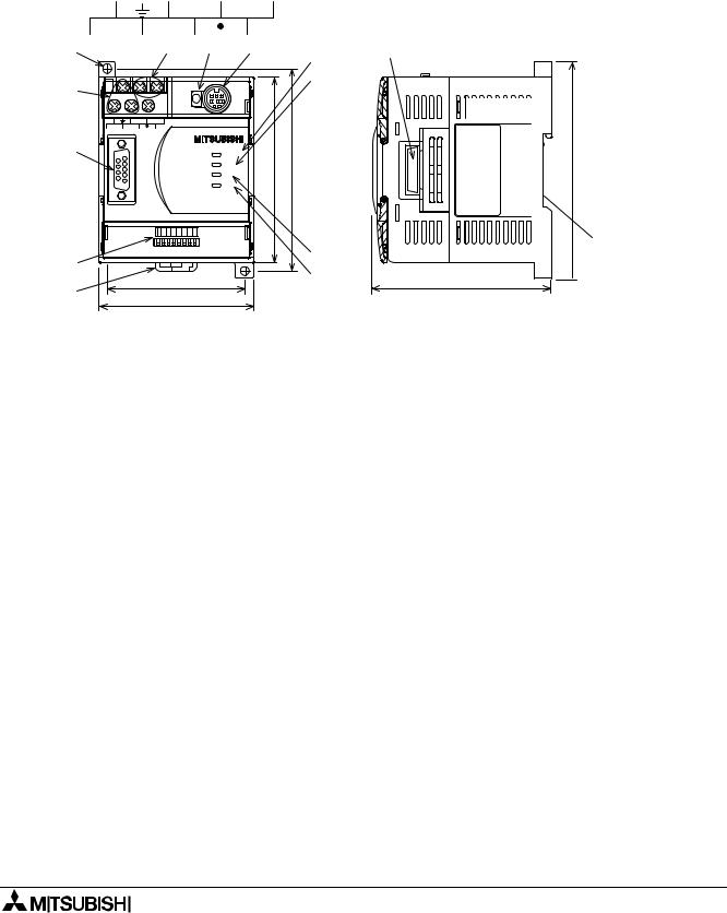
1.2External Dimensions and Each Part Name
|
Dimensions: mm (inches) |
Weight: Approx. 0.4 kg (0.88 lbs) |
Accessory: GSD files (FD: 1 piece)
Figure 1.1:External Dimensions
|
C O M |
) ) |
+ |
||||||
|
2 4 |
||||||||
|
L |
N |
» « |
||||||
|
c ) |
d ) e ) f46) |
g ) |
||||||
|
5 |
8 |
|||||||
|
h ) |
||||||||
|
b ) |
R U N |
. . |
||||||
|
S T O P |
3 3 |
|||||||
|
C O 2M 4 + |
( ( |
|||||||
|
L |
N |
|||||||
|
a ) |
P O W E R |
|||||||
|
R U N |
0 |
8 |
||||||
|
B F |
||||||||
|
D I A |
||||||||
|
F 2X-N 3 2 D 9P —9I F |
||||||||
|
64 32 16 8 4 |
2 |
1 |
O N |
|||||
|
i |
) |
|||||||
|
O F F |
||||||||
|
l ) |
j |
) |
||||||
|
6 7 |
||||||||
|
k ) |
( 2 . 6 4 » ) |
|||||||
|
7 5 |
( 2 . 9 5 » ) |
|||||||
m )
a)Connector for Profibus cable (D-SUB 9 pin)
b)Power supply terminals (screws terminal: M3.5 (0.14″))
c)Direct mounting hole (2-φ4.5 (0.18″))
d)24 V DC power terminal (screws terminal: M3.5 (0.14″))
e)RUN/STOP switch: When this switch is in the RUN position, the 32DP-IF will exchange
data with extension units/blocks and special function blocks. If this switch is in the STOP position, the 32DP-IF will exchange only input data with extension units/blocks.
f)Communication port for FX-20P-E and personal computer
g)POWER LED : ON when AC power is supplied.
|
h) RUN LED |
: ON when 32DP-IF is exchanging data with extension units/blocks and |
|
|
special function blocks. |
||
|
i) |
BF LED |
: ON when a communication error is detected (No data exchange). |
|
j) |
DIA LED |
: ON when notice of diagnostic data is detected. |
k)Hook for mounting DIN rail
l)DIP switches for slave address of this unit
m)Connector for extension cable
n)Groove for mounting DIN rail (DIN rail width: 35 mm (1.38″))
1-2

|
FX2N-32DP-IF Profibus-DP Interface Unit |
Introduction 1 |
1.2.1Pin Configuration
The connector is a 9-pin D-SUB type and the pin configuration is shown below.
Figure 1.2:Pin Layout 9-pin D-SUB
6 7 8 9 1 2 3 4 5
|
Table 1.1: |
Pin Configuration |
|||||
|
Connector |
Signal |
Meaning |
||||
|
3 |
RXD/TXD-P |
Receive/transmit-Data-P(+) |
||||
|
4 |
RTS |
Request to send |
||||
|
Assigned |
5 |
DGND |
Data Ground |
|||
|
Not assigned |
6 |
VP |
Voltage-Plus(+) |
|||
|
8 |
RXD/TXD-N |
Receive/transmit-Data-N(+) |
||||
|
1,2,7,9 |
NC |
Pin not assigned |
||||
1-3
|
FX2N-32DP-IF Profibus-DP Interface Unit |
Introduction 1 |
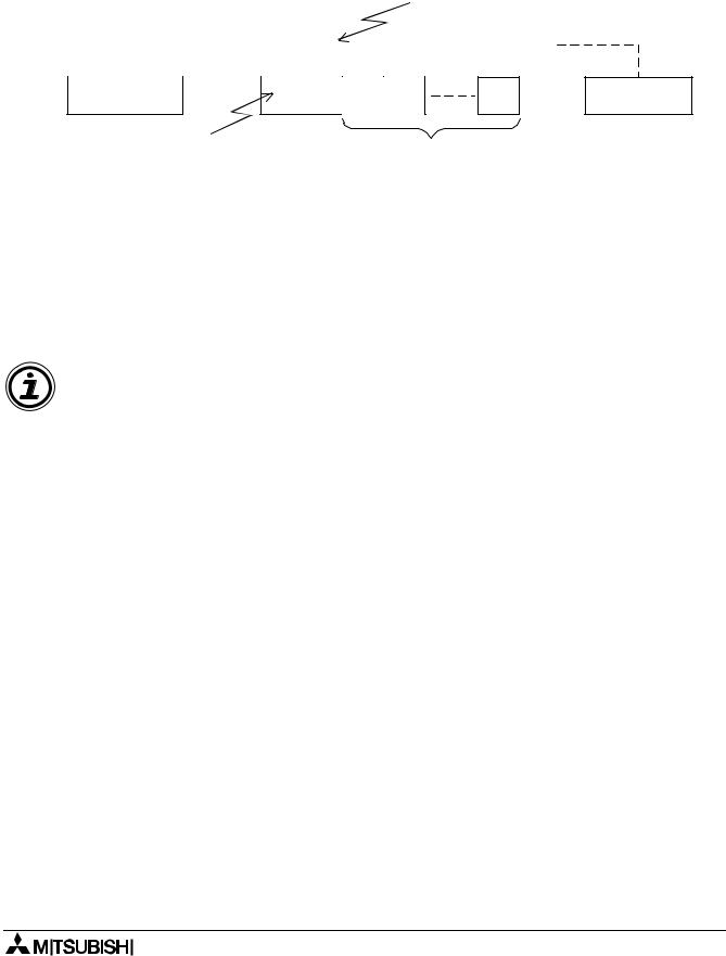
1.3System Configuration
Figure 1.3:System Configuration
|
DP-master |
Profibus-DP network |
|||||||
Slave or DP-master *1
Slave or DP-master *1
|
FX2N-32DP-IF Profibus-DP |
Extension I/O units/blocks and |
|
interface unit *2 |
special function blocks *3 |
*1 The units at each end of the Profibus-DP network must have a terminating resistor. This will either be in the master or slave unit or in the Profibus connector.
*2 For connecting monitoring tool, refer to section 1.3.1
*3 For connecting extension I/O units/blocks and special function blocks, refer to section 1.3.2.
Caution
The parameter data of the 32DP-IF must be set correctly in the DP-master, If the parameter data are not correct, the operation of the module might be affected. For a detailed overview of the parameter of 32DP-IF, refer to chapter 6.
1-4

|
FX2N-32DP-IF Profibus-DP Interface Unit |
Introduction 1 |
1.3.1Connected Programming Tools
An FX-20P-E or personal computer can be used to monitor the devices of the 32DP-IF or to set parameter data for special function blocks connected to the 32DP-IF. For operating instructions of the FX-20P-E or personal computer, refer to their respective operation manuals. For device numbers and explanation, refer to chapter 4.
Connecting cable is same as FX0N/FX2N programmable controller.
Table 1.2: Connected Programming Tools
|
Monitoring Tools |
Description |
||
|
FX-20P-E |
“Device Monitor”, “Data Change” and “Forced ON/OFF” in the Online |
||
|
Monitor /Test mode can be used for supported devices. |
|||
|
Personal Computer |
“Device Edit” and “Entry Data Monitor” can be used for supported |
||
|
(MELSEC MEDOC PLUS) |
devices. |
||
1-5

|
FX2N-32DP-IF Profibus-DP Interface Unit |
Introduction 1 |
1.3.2Connected Extension Units/Blocks
The table below shows extension units/blocks and their data lengths when connected to a 32DP-IF. Data is exchanged between the 32DP-IF and DP-master during every cycle. The maximum amount of data that can be exchanged with the 32DP-IF is 200 bytes of input data and 200 bytes of output data. Please check the specification of the DP-master, it may limit the total amount of exchanged data.
Table 1.3: Connected Extension Units/Blocks and Exchanged Data Length
|
Items |
Description |
Exchange Data Length |
||||||
|
Output Data (Y) |
Input Data (X) |
|||||||
|
FX2N-32ER-ES/UL |
Input = 16 points |
2 Bytes (Y0 ~ Y17) |
2 Bytes (X0 ~ X17) |
|||||
|
Extension I/O Units |
FX2N-32ET-ESS/UL |
Output = 16 points |
||||||
|
FX2N-48ER-ES/UL |
Input = 24 points |
3 Bytes (Y0 ~ Y27) |
3 Bytes (X0 ~ X27) |
|||||
|
FX2N-48ET-ESS/UL |
Output = 24 points |
|||||||
|
FX2N-16EX-ES/UL |
Input = 16 points |
— |
2 Bytes (X0 ~ X17) |
|||||
|
Output = 0 point |
||||||||
|
FX2N |
||||||||
|
FX2N-16EYR-ES/UL |
||||||||
|
Series |
||||||||
|
Input = 0 point |
||||||||
|
FX2N-16EYT-ESS/UL |
2 Bytes (Y0 ~ Y17) |
— |
||||||
|
Output = 16 points |
||||||||
|
FX2N-16EYS-ES/UL |
||||||||
|
FX0N-8EX-UA1/UL |
Input = 8 points |
1 Bytes (X0 ~ X7) |
||||||
|
FX0N-8EX-ES/UL |
Output = 0 point |
— |
||||||
|
Extension |
||||||||
|
Input = 16 points |
||||||||
|
I/O Blocks |
FX0N-16EX-ES/UL |
2 Bytes (X0 ~ X17) |
||||||
|
Output = 0 point |
||||||||
|
FX0N |
FX0N-8ER-ES/UL |
Input = 4 points |
1 Bytes (Y0 ~ Y3) |
1 Bytes (X0 ~ X3) |
||||
|
Output = 4 points |
||||||||
|
Series |
||||||||
|
FX0N-8EYR-ES/UL |
Input = 0 point |
1 Bytes (Y0 ~ Y7) |
||||||
|
FX0N-8EYT-ESS/UL |
Output = 8 points |
|||||||
|
FX0N-16EYR-ES/UL |
Input = 0 point |
2 Bytes (Y0 ~ Y17) |
||||||
|
— |
||||||||
|
FX0N-16EYT-ESS/UL |
Output = 16 points |
|||||||
|
Digital to analog |
8 Bytes, |
|||||||
|
FX2N-4DA |
Analog output data |
|||||||
|
converter |
||||||||
|
(BFM #1 ~ #4) |
||||||||
|
Special Function |
FX2N-4AD |
Analog to digital |
8 Bytes *1 |
|||||
|
converter |
||||||||
|
Blocks |
||||||||
|
FX2N-4AD-PT |
PT100 probe |
— |
8 Bytes *2 |
|||||
|
interface |
||||||||
|
FX2N-4AD-TC |
Thermo-couple |
8 Bytes *3 |
||||||
|
interface |
||||||||
*1 Total 8 bytes, selection between averaged data (BFM #5 ~ #8) or present data (BFM #9 ~ #12) can be done by GSD file configuration for each channel separately.
1-6

|
FX2N-32DP-IF Profibus-DP Interface Unit |
Introduction 1 |
*2 Total 8 bytes, selection between °C and °F, averaged or present data can be done by GSD file configuration for each channel separately.
Table 1.4: BFM No. of FX2N-4AD-PT
|
Items |
BFM No. |
||
|
°C (averaged) |
BFM #5 ~ #8 |
||
|
°C (present) |
BFM #9 ~ #12 |
||
|
°F (averaged) |
BFM #13 ~ #16 |
||
|
°F (present) |
BFM #17 ~ #20 |
||
*3 Total 8 bytes, selection between °C and °F, averaged or present data and the type of thermocouple can be done by GSD file configuration for each channel separately.
Table 1.5: BFM No. of FX2N-4AD-TC
|
Items |
BFM No. |
||
|
°C (averaged) |
BFM #5 ~ #8 |
||
|
°C (present) |
BFM #9 ~ #12 |
||
|
°F (averaged) |
BFM #13 ~ #16 |
||
|
°F (present) |
BFM #17 ~ #20 |
||
1-7

|
FX2N-32DP-IF Profibus-DP Interface Unit |
Introduction 1 |
1.3.3Configuration Rules
1)Special function blocks: Max. 8 blocks per 32DP-IF.
Check the loading on the 5 V DC bus supply. Consumption values for special function blocks can be found in Table 1.7. For maximum available current see the Table 1.6.
2)Maximum I/O points: 256 or less.
3)Check the loading on the 24 V DC service supply. Look up the number of expansion I/O in Figure 1.4. Find the residual current. This can then be used to power sensors etc.
4)Check total exchanged data length in DP-master, this number might be limited by the DPmaster unit. Data length is exchanged between the 32DP-IF and a DP-master in every cycle.
For the data length of connected extension units/blocks, refer to Table 1.3.
However, the maximum amount of data that can be exchanged with the 32DP-IF is 200 byte inputs and 200 byte outputs.
Table 1.6: 24 and 5 V DC Supply Capacity
|
Items |
Power Supply |
||
|
24 V DC Service Supply |
500 mA at 24 V DC |
||
|
Max. 5 V DC Bus Supply |
220 mA at 5 V DC |
||
Table 1.7: Power Supply for Special Function Blocks
|
Number of |
Power Supply |
|||||
|
Model |
Description |
|||||
|
Internal 5 V DC |
External 24 V DC |
|||||
|
I/O Points |
||||||
|
(mA) |
(mA) |
|||||
|
FX2N-4DA |
Digital to analog converter |
8 |
30 |
200 |
||
|
FX2N-4AD |
Analog to digital converter |
8 |
30 |
55 |
||
|
FX2N-4AD-PT |
PT100 probe interface |
8 |
30 |
50 |
||
|
FX2N-4AD-TC |
Thermo-couple interface |
8 |
30 |
50 |
||
Figure 1.4:Number of Expansion I/O and 24 V DC Service Supply Capacity (mA)
Number of additional output (points)
|
> 32 |
|||||||||||
|
Invalid configuration |
|||||||||||
|
32 |
200 |
150 |
100 |
50 |
0 |
||||||
|
24 |
275 |
225 |
175 |
125 |
75 |
25 |
|||||
|
16 |
350 |
300 |
250 |
200 |
150 |
100 |
50 |
0 |
|||
|
8 |
425 |
375 |
325 |
275 |
225 |
175 |
125 |
75 |
25 |
||
|
0 |
500 |
450 |
400 |
350 |
300 |
250 |
200 |
150 |
100 |
||
|
0 |
8 |
16 |
24 |
32 |
40 |
48 |
56 |
64 |
> 64 |
||
Number of additional input (points)
For extension unit, refer to FX2N Series Hardware Manual.
1-8

|
FX2N-32DP-IF Profibus-DP Interface Unit |
Introduction 1 |
1.3.4Example Configuration
Figure 1.5:Example Configuration
A Series
PLC
|
Profibus-DP |
|||||||||
|
network |
A1SJ71PB92 (software version E) |
||||||||
|
FX2N— |
FX2N-16EX |
FX2N-16EYT |
FX2N— |
FX2N— |
FX2N— |
||||
|
32DP-IF |
-ES/UL |
-ESS/UL |
4AD |
4DA |
4DA |
||||
For configuration rules, refer to section 1.3.3.
1)Check special function blocks.
a)Count special function blocks.
This 32DP-IF has 3 special function blocks connected (FX2N-4AD × 1, FX2N-4DA × 2). This configuration is OK as the total number of blocks is less than 8.
b)Check the loading on the 5 V DC bus supply. Consumption values for special function blocks can be found in Table 1.7. For maximum available current see the Table 1.6.
Table 1.8: Check 5 V DC Bus Supply
|
Items |
Internal 5 V DC |
External 24 V DC |
||
|
FX2N-4AD |
30 mA |
55 mA |
||
|
FX2N-4DA |
30 mA |
200 mA |
||
|
FX2N-4DA |
30 mA |
200 mA |
||
|
Total Consumption Values |
90 mA <220 mA |
455 mA |
||
This configuration is OK as the 5 V DC bus supply consumption value is less than 220 mA (5 V DC bus supply capacity).
However, this system needs a supply of 455 mA from an external 24 V DC power supply, for the special function blocks. In this case, the 32DP-IF can supply 250 mA for external 24 V DC. See next page (check the loading on the 24 V DC service supply)
1-9

|
FX2N-32DP-IF Profibus-DP Interface Unit |
Introduction 1 |
2)Check total I/O points and the loading on the 24 V DC service supply. For the loading on the 24 V DC service supply, refer to Figurer 1.4.
Table 1.9: Check Total I/O Points and the Loading on the 24 V DC Service Supply
|
Addressable I/O |
24 V DC Service Supply |
|||||||
|
Units/Block Name |
Special |
|||||||
|
Inputs |
Outputs |
Function |
Sum I/O |
Sum |
||||
|
(X) |
(Y) |
Blocks |
||||||
|
(X/Y) |
||||||||
|
FX2N-32DP-IF |
0 |
0 |
— |
|||||
|
Inputs (X) = 16 |
+ 250 mA |
|||||||
|
FX2N-16EX-ES/UL |
16 |
0 |
— |
|||||
|
Outputs (Y) = 16 |
According to Figure 1.4 |
|||||||
|
FX2N-16EYT-ESS/UL |
0 |
16 |
— |
|||||
|
FX2N-4AD |
— |
— |
8 |
— |
0 mA |
|||
|
FX2N-4DA |
— |
— |
8 |
— |
0 mA |
|||
|
FX2N-4DA |
— |
— |
8 |
— |
0 mA |
|||
|
16 |
16 |
24 |
This configuration can supply 250 mA at |
|||||
|
Total I/O is 56 points <256 points |
24 V DC service supply for other usages. |
|||||||
This configuration is OK as the total I/O points are less than 256. It is also OK with the loading on the 24 V DC service supply, this configuration can supply 250 mA at 24 V DC service supply for other usages.
3)Check the total allowable exchanged data length for each input data and output data in the DP-master, because this number might be limited by the DP-master unit.
Maximum exchanged data length of 32DP-IF can be found in Table 3.3. For the data length of connected extension units/blocks, refer to Table 1.3.
Table 1.10:Check Total Exchanged Data Length
|
Units/Blocks Name |
Exchanged Data Length |
|||
|
Input Data |
Output Data |
|||
|
FX2N-16EX-ES/UL |
2 bytes |
0 byte |
||
|
FX2N-16EYT-ESS/UL |
0 byte |
2 bytes |
||
|
FX2N-4AD |
8 bytes |
0 byte |
||
|
FX2N-4DA |
0 byte |
8 bytes |
||
|
FX2N-4DA |
0 byte |
8 bytes |
||
|
Total exchanged data length |
10 bytes < 200 bytes *1 |
18 bytes < 200 bytes *1 |
||
|
<244 bytes *2 |
<244 bytes *2 |
|||
*1 This value is maximum exchanged data length of 32DF-IF.
*2 This example configuration use A series programmable controllers A1SJ71PB92D (software version is E). This DP-master is limited to 244 bytes of input data and 244 bytes of output data.
This configuration is OK as the each total input data and total output data length is less than 200 bytes.
1-10
![]()
|
FX2N-32DP-IF Profibus-DP Interface Unit |
Wiring and Mounting Arrangements 2 |
2.Wiring and Mounting Arrangements
2.1Mounting Arrangements
To prevent a rise in temperature, mount the units to back walls. Never mount them to the floor, ceiling or side wall of an enclosure.
Figure 2.1:Mounting Location
> 50 mm
FX2N-32DP-IF
(1.97″)
> 50 mm (1.97″)
|
FX2N-4DA |
FX2N-4AD |
FX2N-16EX -ES/UL |
|
> 50 mm (1.97″)
FX2N-16EYT
-ESS/UL
> 50 mm (1.97″)
Figure 2.2:Mounting Arrangement
2-1
 Loading…
- Инструкции и руководства
- Бренды
- Mitsubishi Electronics
- MELSEC FX2N
- Справочник Пользователя
MELSEC FX2N series
Programmable Controller
Hardware Manual
FX2N
66014
JY992D66301-H
MITSUBISHI ELECTRIC
Art.No.:
2001 05 07
MITSUBISHI ELECTRIC
INDUSTRIAL AUTOMATION

- 1
- 2
- 3
- 4
- 5
- 6
- 7
- 8
- 9
- 10
- 11
- 12
- 13
- 14
- 15
- 16
- 17
- 18
- 19
- 20
- 21
- 22
- 23
- 24
- 25
- 26
- 27
- 28
- 29
- 30
- 31
- 32
- 33
- 34
- 35
- 36
- 37
- 38
- 39
- 40
- 41
- 42
- 43
- 44
- 45
- 46
- 47
- 48
- 49
- 50
- 51
- 52
- 53
- 54
- 55
- 56
- 57
- 58
- 59
- 60
- 61
- 62
- 63
- 64
- 65
- 66
- 67
- 68
- 69
- 70
- 71
- 72
- 73
- 74
- 75
- 76
- 77
- 78
- 79
- 80
- 81
- 82
- 83
- 84
- 85
- 86
- 87
- 88
- 89
- 90
- 91
- 92
- 93
- 94
- 95
- 96
- 97
- 98
- 99
- 100
- 101
- 102
- 103
- 104
- 105
- 106
- 107
- 108
- 109
- 110
- 111
- 112
- 113
- 114
- 115
- 116
- 117
- 118
- 119
- 120
- 121
- 122
- 123
- 124
- 125
- 126
- 127


R100

Mitsubishi R100 User manual,
102 pages
SH-080007
Mitsubishi SH-080007 User`s manual,
424 pages
E1032
Mitsubishi E1032 User`s guide,
65 pages
R100
Mitsubishi R100 User`s manual,
272 pages
QJ71C24/-R2

Módulos de Comunicación QJ71C24/-R2, QJ71C24N/-R2/ [en] ,
542 pages
QJ71C24/-R2
Mitsubishi QJ71C24/-R2 Specifications,
66 pages
A8GT-50KBF
Mitsubishi A8GT-50KBF Specifications,
33 pages
2404f
INDEX Application Guide,
230 pages
QJ71C24/-R2
G3 Communication with Mitsubishi Q PLC over [en] ,
7 pages
2408f
Mitsubishi 2408f Product manual,
30 pages
QJ71C24/-R2
Mitsubishi QJ71C24/-R2 User`s manual,
24 pages
DS5000TK
Mitsubishi DS5000TK User`s guide,
174 pages
MIM-A01
Mitsubishi MIM-A01 Specifications,
62 pages
SH-080007
Mitsubishi SH-080007 User`s manual,
74 pages
MIM-G01
Mitsubishi MIM-G01 Specifications,
136 pages
R100
Mitsubishi Electric Air Conditioner CITY MULTI Twinning Kit,
4 pages
A8GT-50KBF
Mitsubishi A8GT-50KBF Specifications,
27 pages
MAM-AM20
Modems Product Information,
4 pages
A8GT-50KBF
Mitsubishi A8GT-50KBF User`s manual,
124 pages
QJ71C24/-R2
Mitsubishi QJ71C24/-R2 User`s manual,
358 pages