- Manuals
- Brands
- Endress+Hauser Manuals
- Measuring Instruments
- Deltabar S PMD75
Manuals and User Guides for Endress+Hauser Deltabar S PMD75. We have 15 Endress+Hauser Deltabar S PMD75 manuals available for free PDF download: Operating Instructions Manual, Technical Information, Brief Operating Instructions, Special Documentation, Installation Instructions Manual
Endress+Hauser Deltabar S PMD75 Operating Instructions Manual (238 pages)
Description of Device Functions
Brand: Endress+Hauser
|
Category: Measuring Instruments
|
Size: 10.19 MB
Table of Contents
-
Table of Contents
5
-
1 Notes on Use
6
-
Finding Parameter Descriptions Using ID Numbers
6
-
Finding Function Groups Using Graphic Representation
6
-
Finding Parameter Descriptions Using Parameter Names
6
-
(Index)
6
-
-
-
2 Parameter Description of Local Operation and Fieldcare
7
-
3 Graphic Representation of Function Groups
11
-
Representation Via Device Display
11
-
Representation in Fieldcare
12
-
-
4 Pressure Measurement (FF Configuration Program)
13
-
5 Level Measurement (FF Configuration Program)
14
-
Overview of Level Measurement
14
-
Level Easy Pressure» Level Selection
15
-
Level Easy Height» Level Selection
19
-
Level Standard» Level Selection, «Linear» Level Mode
23
-
Level Standard» Level Selection
27
-
Pressure Linearized» Level Mode
27
-
-
Height Linearized» Level Mode
31
-
-
6 Flow Measurement (FF Configuration Program)
34
-
Calibration
34
-
Totalizer
36
-
-
7 Parameter Description (FF Configuration Program)
38
-
Cerabar S/Deltabar S/Deltapilot S Block Model
38
-
Resource Block
41
-
Transducer Blocks
51
-
Analog Input Block (Function Block)
93
-
-
8 Pressure Measurement (Via Local Operation and Fieldcare)
104
-
9 Level Measurement (Via Local Operation and Fieldcare)
105
-
Overview of Level Measurement
105
-
Level Easy Pressure» Level Selection
106
-
Level Easy Height» Level Selection
110
-
Level Standard» Level Selection, «Linear» Level Mode
114
-
Level Standard» Level Selection
118
-
Pressure Linearized» Level Mode
118
-
Height Linearized» Level Mode
124
-
-
10 Flow Measurement (Via Local Operation and Fieldcare)
129
-
Calibration
129
-
Totalizer
131
-
-
Parameter Description (Local Operation and Fieldcare)
133
-
12 Troubleshooting
209
-
Messages
209
-
Response of Outputs to Errors
219
-
Confirming Messages
220
-
-
13 Appendix
221
-
Operating Menu
221
-
-
Index
231
Advertisement

Endress+Hauser Deltabar S PMD75 Operating Instructions Manual (162 pages)
Process pressure / Differential pressure, Flow / Hydrostatic
Brand: Endress+Hauser
|
Category: Transmitter
|
Size: 2.07 MB
Table of Contents
-
Table of Contents
3
-
1 Notes on Use
4
-
Finding Parameter Description Using ID Numbers
4
-
Finding Function Group Using Graphic Representation
4
-
Finding Parameter Description Using Parameter Names (Index)
4
-
-
2 Finding Parameter Description Using
5
-
ID Numbers
5
-
3 Graphic Representation of Function Groups
9
-
4 Pressure Measurement
11
-
5 Level Measurement
12
-
Overview of Level Measurement
12
-
Level Easy Pressure» Level Selection
13
-
Level Easy Height» Level Selection
17
-
Level Standard» Level Selection, «Linear» Level Type
21
-
Level Standard» Level Selection, «Pressure Linearized» Level Type
25
-
Level Standard» Level Selection, «Height Linearized» Level Type
31
-
-
6 Flow Measurement
38
-
Calibration
38
-
Totalizers
40
-
-
7 Description of Parameters
41
-
Measuring Mode
42
-
Level Selection
43
-
Calib. Offset
51
-
BASIC SETUP Pressure
52
-
BASIC SETUP Level
55
-
Full Pressure
58
-
Height Unit
61
-
Empty Height
62
-
Full Height
63
-
Level Mode
65
-
Lin. Measurand
67
-
Tank Volume
72
-
Tank Height
73
-
Lind. MEASURAND
76
-
Hydr. Press Max
78
-
Comb.measurand
80
-
Level Max
83
-
Flow-Meas. Type
90
-
Mass Flow Unit
91
-
Cust. Unit Fact. F
92
-
EXTENDED SETUP Pressure
93
-
Process Density
94
-
Set.l.fl.cut-Off
95
-
Tank Content Max
96
-
Lin. Edit Mode
97
-
MEASURING TABLE (Display)
98
-
Linearization
99
-
Fact.u.u.total.1
103
-
Fact. U. U. Total. 2
104
-
Menu Descriptor
105
-
Display Contrast
106
-
Ai out Value
107
-
DEVICE SERIAL no
108
-
Software Version
109
-
Mat. Proc. Conn
110
-
SENSOR SER. no
111
-
PROCESS VALUES Pressure
112
-
PROCESS VALUES Level
113
-
-
Level before Lin
114
-
Suppressed Flow
115
-
COUNTER T>Tmax
116
-
Reset Peakhold
117
-
Download Funct
118
-
Simulation Mode
119
-
Alarm Status
120
-
Alarm Delay
121
-
Pminalarm WINDOW
122
-
-
-
8 Slot/Index Tables
142
-
9 Troubleshooting
148
-
Messages
148
-
Response of Outputs to Errors
156
-
Confirming Messages
158
-
-
Index
159
Endress+Hauser Deltabar S PMD75 Technical Information (84 pages)
Differential pressure measurement
Differential pressure transmitter with ceramic and silicon sensors
Overload-resistant and function-monitored, Communication via
HART, PROFIBUS PA or FOUNDATION Fieldbus
Brand: Endress+Hauser
|
Category: Measuring Instruments
|
Size: 2.24 MB
Table of Contents
-
Table of Contents
2
-
Function and System Design
4
-
Device Selection
4
-
Measuring Principle
5
-
Flow Measurement
6
-
Level Measurement (Level, Volume and Mass)
7
-
Communication Protocol
7
-
-
Input
8
-
Measured Variable
8
-
Measuring Range
8
-
Explanation of Terms
9
-
-
Output
10
-
Output Signal
10
-
Signal Range — 4
10
-
Signal on Alarm
10
-
Load — 4
10
-
Resolution
10
-
Dynamic Behavior Current Output
11
-
Dynamic Behavior HART
11
-
Dynamic Behavior PROFIBUS PA
12
-
Dynamic Behavior FOUNDATION Fieldbus
12
-
Damping
13
-
Data of the FOUNDATION
13
-
Fieldbus Interface
13
-
-
Power Supply
15
-
Electrical Connection
15
-
Supply Voltage
18
-
Current Consumption
18
-
Cable Entry
18
-
Cable Specification
18
-
Residual Ripple
18
-
Influence of Power Supply
18
-
-
Performance Characteristics — General
19
-
Reference Operating Conditions
19
-
Long-Term Stability
19
-
Influence of the Installation Position
19
-
Vibration Effects
19
-
-
Performance Characteristics — Metallic Process Isolating Diaphragms
20
-
Reference Accuracy — PMD75, FMD77, FMD78
20
-
Total Performance — PMD75
20
-
Total Error
20
-
Warm-Up Period — PMD75, FMD77, FMD78
21
-
Influence of the Operating Pressure on Zero Point and Span — PMD75, FMD77, FMD78
21
-
Thermal Change of the Zero Output and the Output Span — PMD75
21
-
-
Performance Characteristics — Ceramic Process Isolating Diaphragms
22
-
Reference Accuracy — PMD70, FMD76
22
-
Total Performance — PMD70, FMD76
22
-
Total Error
22
-
Warm-Up Period — PMD70, FMD76
22
-
Influence of the Operating Pressure on Zero Point and Span — PMD70, FMD76
22
-
Thermal Change of the Zero Output and the Output Span — PMD70, FMD76
22
-
-
Operating Conditions (Installation)
23
-
General Installation Instructions
23
-
Measuring Arrangement
23
-
Heat Insulation — FMD77
24
-
Wall- and Pipe-Mounting
24
-
Separate Housing» Version
25
-
Turn the Housing
26
-
Oxygen Applications
26
-
Ultra Pure Gas Applications
26
-
Process Isolating Diaphragms for Materials with Hydrogen Build-Up (Gold-Rhodium Coating)
27
-
-
Operating Conditions (Environment)
27
-
Ambient Temperature Range
27
-
Storage Temperature Range
27
-
Degree of Protection
27
-
Climate Class
27
-
Vibration Resistance
27
-
Electromagnetic Compatibility
27
-
Overvoltage Protection (Optional)
28
-
-
Operating Conditions (Process)
28
-
Process Temperature Limits
28
-
Process Temperature Range, Seals
28
-
Pressure Specifications
29
-
-
Mechanical Construction
30
-
Housing Dimensions T14, Optional Display on the Side
30
-
Housing Dimensions T15, Optional Display on the Top
30
-
Housing Dimensions T17, Optional Display on the Top
30
-
Diaphragms
31
-
Process Connections PMD70 with Ceramic Process Isolating (Continued)
32
-
Process Connections PMD75 with Metallic Process Isolating Diaphragms
33
-
Diaphragms (Continued)
34
-
Diaphragms (Continued)
35
-
Process Connection FMD76 with Ceramic Process Isolating
36
-
Diaphragms
36
-
Diaphragms (Continued)
37
-
Process Connection FMD76 with Ceramic Process Isolating
38
-
Diaphragms (Continued)
38
-
Process Connections FMD77 with Metallic Process Isolating
38
-
Diaphragms, Low-Pressure Side
38
-
Process Connections FMD77 with Metallic Process Isolating Diaphragms, High-Pressure Side
39
-
Process Connections FMD77 with Metallic Process Isolating Diaphragms, High-Pressure Side (Continued)
40
-
Process Connections FMD77 with Metallic Process Isolating Diaphragms, High-Pressure Side (Continued)
41
-
FMD78 Basic Unit
42
-
Process Connection FMD78 with Metallic Process Isolating Diaphragm
43
-
Diaphragm (Continued)
44
-
Process Connection FMD78 with Metallic Measuring Diaphragms (Continued)
45
-
Process Connection FMD78 with Metallic Measuring Diaphragms (Continued)
46
-
Process Connection FMD78 with Metallic Measuring Diaphragms (Continued)
47
-
Process Connection FMD78 with Metallic Measuring Diaphragms (Continued)
48
-
Process Connection FMD78 with Metallic Measuring Diaphragms (Continued)
49
-
Separate Housing» Version
50
-
Weight
51
-
Material
51
-
-
Human Interface
53
-
Operating Elements
53
-
Local Operation
55
-
Remote Operation
55
-
Hard- und Software for On-Site and Remote Operation
56
-
-
Planning Instructions, Diaphragm Seal Systems
58
-
Applications
58
-
Design and Operation Mode
58
-
Diaphragm Seal Filling Oils
59
-
Influence of the Temperature on the Zero Point
60
-
Ambient Temperature Range
62
-
Response Time
62
-
Installation Instructions
64
-
-
Certificates and Approvals
66
-
CE Mark
66
-
Ex Approvals
66
-
Marine Certificate
66
-
Functional Safety SIL / IEC 61508 Declaration of Conformity (Optional)
66
-
Overspill Protection
66
-
CRN Approvals
66
-
Pressure Equipment Directive (PED)
66
-
Standards and Guidelines
66
-
-
Ordering Information
67
-
Pmd70
67
-
PMD70 (Continued)
68
-
PMD70 (Continued)
69
-
Pmd75
70
-
PMD75 (Continued)
71
-
PMD75 (Continued)
72
-
Fmd76
73
-
FMD76 (Continued)
74
-
FMD76 (Continued)
75
-
Fmd77
76
-
FMD77 (Continued)
77
-
FMD77 (Continued)
78
-
Fmd78
79
-
FMD78 (Continued)
80
-
FMD78 (Continued)
81
-
-
Additional Documentation
82
-
Field of Activities
82
-
Technical Information
82
-
Operating Instructions
82
-
Brief Operating Instructions
82
-
Manual for Functional Safety (SIL)
82
-
Safety Instructions
82
-
Installation/Control Drawings
83
-
Overspill Protection
84
-
Advertisement
Endress+Hauser Deltabar S PMD75 Operating Instructions Manual (114 pages)
Differential pressure measurement
Brand: Endress+Hauser
|
Category: Measuring Instruments
|
Size: 5.02 MB
Table of Contents
-
Table of Contents
3
-
1 Document Information
4
-
Document Function
4
-
Symbols Used
4
-
Registered Trademarks
5
-
Terms and Abbreviations
6
-
Turn down Calculation
7
-
-
2 Basic Safety Instructions
8
-
Requirements Concerning the Staff
8
-
Designated Use
8
-
Workplace Safety
8
-
Operational Safety
8
-
Hazardous Area
9
-
Product Safety
9
-
-
3 Identification
10
-
Product Identification
10
-
Device Designation
10
-
Scope of Delivery
12
-
CE Mark, Declaration of Conformity
12
-
Registered Trademarks
12
-
-
4 Installation
13
-
Incoming Acceptance and Storage
13
-
Installation Conditions
13
-
Installation Instructions
14
-
Post-Installation Check
30
-
-
5 Wiring
31
-
Connecting the Device
31
-
Connecting the Measuring Unit
32
-
Overvoltage Protection (Optional)
33
-
Post-Connection Check
33
-
-
6 Operation
34
-
Onsite Display (Optional)
34
-
Operating Elements
36
-
FOUNDATION Fieldbus Interface
38
-
Local Operation — Onsite Display Connected
51
-
Historom®/M-DAT (Optional)
54
-
Fieldcare
57
-
Locking/Unlocking Operation
57
-
Simulation
59
-
Factory Setting (Reset)
59
-
-
7 Commissioning
62
-
Configuring Messages
62
-
Function Check
62
-
Commissioning Via an FF Configuration Program
62
-
Selecting the Language and Measuring Mode
64
-
Position Adjustment
65
-
Flow Measurement
67
-
Level Measurement
70
-
Differential Pressure Measurement
77
-
Scaling the out Parameter
79
-
Configuring Event Behavior in Accordance with
80
-
FOUNDATION Fieldbus Specification FF912 Field
80
-
Diagnostic Profile
80
-
-
-
8 Maintenance
91
-
Cleaning Instructions
91
-
Exterior Cleaning
91
-
-
9 Diagnostics and Troubleshooting
92
-
Troubleshooting
92
-
Diagnostic Information on Local Display
93
-
Diagnostic Event in the Operating Tool
94
-
Diagnostic Messages in the DIAGNOSTIC Transducer Block (TRDDIAG)
95
-
Overview of Diagnostic Events
99
-
Response of Outputs to Errors
108
-
Confirming Messages
109
-
Repair
109
-
Repair of Ex-Certified Devices
110
-
Spare Parts
110
-
Return
110
-
Disposal
110
-
Software History
111
-
-
10 Technical Data
111
-
Index
112

Endress+Hauser Deltabar S PMD75 Operating Instructions Manual (156 pages)
Process pressure / Differential pressure, Flow / Hydrostatic
Brand: Endress+Hauser
|
Category: Transmitter
|
Size: 6.78 MB
Table of Contents
-
Table of Contents
3
-
Notes on Use
4
-
Finding Parameter Description Using ID Numbers
4
-
Finding Function Group Using Graphic Representation
4
-
Finding Parameter Description Using Parameter Names (Index)
4
-
Finding Parameter Description Using
5
-
ID Numbers
5
-
Graphic Representation of Function Groups
10
-
Pressure Measurement
11
-
Calibration with Reference Pressure
11
-
Calibration Without Reference Pressure
12
-
Level Measurement
14
-
Overview of Level Measurement
14
-
Level Easy Pressure» Level Selection
15
-
Level Easy Height» Level Selection
19
-
Level Standard» Level Selection, «Linear» Level Type
24
-
Level Standard» Level Selection, «Pressure Linearized» Level Type
28
-
Level Standard» Level Selection, «Height Linearized» Level Type
33
-
Flow Measurement
40
-
Calibration
40
-
Totalizers
43
-
Description of Parameters
44
-
Trouble-Shooting
132
-
Messages
132
-
Response of Outputs to Errors
141
-
Confirming Messages
142
-
Appendix
142
-
Operating Menu for On-Site Display, Digital Communication
142
-
Index
151
Endress+Hauser Deltabar S PMD75 Operating Instructions Manual (100 pages)
Differential pressure measurement
Brand: Endress+Hauser
|
Category: Measuring Instruments
|
Size: 5.46 MB
Table of Contents
-
Table of Contents
3
-
Safety Instructions
4
-
Designated Use
4
-
Installation, Commissioning and Operation
4
-
Operational Safety and Process Safety
4
-
Notes on Safety Conventions and Icons
5
-
Identification
6
-
Device Designation
6
-
Scope of Delivery
9
-
CE Mark, Declaration of Conformity
9
-
Registered Trademarks
9
-
Installation
10
-
Incoming Acceptance and Storage
10
-
Installation Conditions
10
-
Installation Instructions
10
-
Post-Installation Check
22
-
Wiring
23
-
Connecting the Device
23
-
Connecting the Measuring Unit
24
-
Post-Connection Check
25
-
Operation
26
-
On-Site Display (Optional)
26
-
Operating Elements
28
-
PROFIBUS PA Communication Protocol
31
-
On-Site Operation — On-Site Display Connected
44
-
Fieldcare
47
-
Historom®/M-DAT (Optional)
47
-
Locking/Unlocking Operation
50
-
Configuring the Device Address
51
-
Factory Setting (Reset)
52
-
Commissioning
54
-
Function Check
54
-
Commissioning Via Class 2 Master (Fieldcare)
55
-
Selecting Language and Measuring Mode
55
-
Position Adjustment
57
-
Flow Measurement
58
-
Level Measurement
61
-
Differential Pressure Measurement
68
-
Scaling out Value
70
-
System Units (SET UNIT to BUS)
71
-
System Integration
72
-
Maintenance
74
-
Exterior Cleaning
74
-
Trouble-Shooting
75
-
Messages
75
-
Response of Outputs to Errors
82
-
Confirming Messages
83
-
Repair
84
-
Repair of Ex-Certified Devices
84
-
Spare Parts
85
-
Returning the Device
86
-
Disposal
86
-
Software History
86
-
Hardware History
86
-
Technical Data
87
-
Appendix
87
-
Menu
87
-
Patents
95
-
Index
96

Endress+Hauser Deltabar S PMD75 Operating Instructions Manual (96 pages)
Brand: Endress+Hauser
|
Category: Measuring Instruments
|
Size: 4.92 MB
Table of Contents
-
Table of Contents
3
-
1 Safety Instructions
4
-
Designated Use
4
-
Installation, Commissioning and Operation
4
-
Operational Safety and Process Safety
4
-
Notes on Safety Conventions and Icons
5
-
-
2 Identification
6
-
Device Designation
6
-
Scope of Delivery
9
-
CE Mark, Declaration of Conformity
9
-
Registered Trademarks
9
-
-
3 Installation
10
-
Incoming Acceptance and Storage
10
-
Installation Conditions
10
-
Installation Instructions
10
-
Post-Installation Check
23
-
-
4 Wiring
24
-
Connecting the Device
24
-
Connecting the Measuring Unit
25
-
Overvoltage Protection (Optional)
26
-
Post-Connection Check
26
-
-
5 Operation
27
-
Onsite Display (Optional)
27
-
Operating Elements
28
-
FOUNDATION Fieldbus Interface
32
-
Local Operation — On-Site Display Connected
45
-
Fieldcare
48
-
Historom®/M-DAT (Optional)
48
-
Locking/Unlocking Operation
50
-
Simulation
52
-
Factory Setting (Reset)
52
-
-
6 Commissioning
55
-
Function Check
55
-
Commissioning Via an FF Configuration Program
55
-
Selecting the Language and Measuring Mode
57
-
Position Adjustment
58
-
Flow Measurement
59
-
Level Measurement
62
-
Differential Pressure Measurement
69
-
Scaling the out Parameter
71
-
-
7 Maintenance
72
-
Exterior Cleaning
72
-
-
8 Troubleshooting
72
-
Messages
72
-
Response of Outputs to Errors
81
-
Confirming Messages
82
-
Repair
82
-
Repair of Ex-Certified Devices
82
-
Spare Parts
83
-
Return
84
-
Disposal
84
-
Software History
84
-
-
10 Appendix
85
-
Menu
85
-
-
9 Technical Data
85
-
Index
95
Endress+Hauser Deltabar S PMD75 Operating Instructions Manual (112 pages)
Differential pressure measurement
Brand: Endress+Hauser
|
Category: Measuring Instruments
|
Size: 6.88 MB
Endress+Hauser Deltabar S PMD75 Brief Operating Instructions (52 pages)
Differential pressure measurement
Brand: Endress+Hauser
|
Category: Measuring Instruments
|
Size: 1.29 MB
Table of Contents
-
Serial Number
2
-
Table of Contents
3
-
1 Document Information
4
-
Document Function
4
-
Symbols Used
4
-
Safety Symbols
4
-
Electrical Symbols
4
-
-
Registered Trademarks
6
-
Terms and Abbreviations
7
-
Turn down Calculation
8
-
-
2 Basic Safety Instructions
9
-
Requirements Concerning the Staff
9
-
Designated Use
9
-
Workplace Safety
9
-
Operational Safety
9
-
Hazardous Area
10
-
Product Safety
10
-
-
3 Identification
10
-
Product Identification
10
-
Device Designation
11
-
Scope of Delivery
11
-
CE Mark, Declaration of Conformity
12
-
Registered Trademarks
12
-
-
4 Installation
13
-
Incoming Acceptance and Storage
13
-
Installation Conditions
14
-
Installation Instructions
14
-
Post-Installation Check
21
-
-
5 Wiring
22
-
Connecting the Device
22
-
Connecting the Measuring Unit
23
-
Overvoltage Protection (Optional)
24
-
Post-Connection Check
24
-
-
6 Operation
25
-
Onsite Display (Optional)
25
-
Operating Elements
27
-
FOUNDATION Fieldbus Interface
30
-
Local Operation — Onsite Display Connected
31
-
Menu Structure
31
-
Historom®/M-DAT (Optional)
35
-
Fieldcare
35
-
Locking/Unlocking Operation
35
-
Simulation
36
-
Factory Setting (Reset)
36
-
-
7 Commissioning
36
-
Configuring Messages
36
-
Function Check
36
-
Commissioning Via an FF Configuration Program
37
-
Selecting the Language and Measuring Mode
37
-
Position Adjustment
37
-
Flow Measurement
38
-
Level Measurement
42
-
Differential Pressure Measurement
48
-
Scaling the out Parameter
51
-
Endress+Hauser Deltabar S PMD75 Special Documentation (40 pages)
Functional Safety Manual, Pressure, differential pressure, level and flow measurement with 4 to 20 mA output signal
Brand: Endress+Hauser
|
Category: Industrial Equipment
|
Size: 2.88 MB
Table of Contents
-
Table of Contents
2
-
SIL Declaration of Conformity
3
-
Safety-Related Parameters
4
-
Useful Lifetime of Electric Components
5
-
-
Certificate
6
-
About this Document
7
-
Document Purpose
7
-
Symbols Used
7
-
Supplementary Device Documentation
8
-
-
Permitted Devices Types
9
-
SIL Label on the Nameplate
10
-
-
Safety Function
11
-
Definition of the Safety Function
11
-
Safety-Related Signal
11
-
Restrictions for Use in Safety-Related Applications
11
-
-
Use in Protective Systems
13
-
Device Behavior During Operation
13
-
Confirmation and Locking Methods
15
-
Increased Security During Parameter Entry Via Onsite Display
16
-
Field Communicator or Fieldcare/Devicecare
16
-
Standard Parameter Entry Via Onsite Display, Field Communicator or Fieldcare/Devicecare
20
-
Conditions for Safe Measuring Mode
21
-
Checks
22
-
Locking/Unlocking
23
-
Proof-Test
23
-
-
Life Cycle
25
-
Requirements for Personnel
25
-
Installation
25
-
Commissioning
25
-
Operation
25
-
Maintenance
25
-
Repair
25
-
Modification
26
-
Decommissioning
26
-
-
Appendix
27
-
Measuring System Design
27
-
Notes on the Redundant Connection of Multiple Sensors
27
-
For SIL 3
27
-
Additional Information
27
-
Change History
28
-
-
Parameter Description
29
-
Pressure» Operating Mode
29
-
-
Form for Device Configuration — Pressure
33
-
Form for Device Configuration — Level
35
-
Form for Device Configuration — Flow
37
Endress+Hauser Deltabar S PMD75 Operating Instructions Manual (44 pages)
Differential pressure measurement
Brand: Endress+Hauser
|
Category: Measuring Instruments
|
Size: 0.98 MB
Table of Contents
-
Table of Contents
2
-
1 Safety Instructions
3
-
Designated Use
3
-
Installation, Commissioning and Operation
3
-
Operational Safety and Process Safety
3
-
Return
3
-
Safety Icons
4
-
-
2 Product Identification
4
-
3 Installation
4
-
General Installation Instructions
4
-
Measuring Arrangement
5
-
Installation Instructions for Devices with Diaphragm Seals (FMD78)
7
-
Assembling and Mounting the «Separate Housing» Version
9
-
-
4 Wiring
10
-
Connecting the Device
10
-
Connecting the Measuring Unit
11
-
-
5 Operation
13
-
Onsite Display (Optional)
13
-
Operating Elements
15
-
Onsite Operation Via Onsite Display
17
-
Locking/Unlocking Operation
21
-
-
6 Commissioning
22
-
Commissioning Via an FF Configuration Program
22
-
Selecting the Language and Measuring Mode
24
-
Position Adjustment
25
-
Flow Measurement
26
-
Level Measurement
31
-
Differential Pressure Measurement
39
-
Scaling the out Parameter
42
-

Endress+Hauser Deltabar S PMD75 Brief Operating Instructions (32 pages)
Differential pressure measurement
Brand: Endress+Hauser
|
Category: Measuring Instruments
|
Size: 0.74 MB
Table of Contents
-
Table of Contents
2
-
Safety Instructions
3
-
Designated Use
3
-
Installation, Commissioning and Operation
3
-
Operational Safety and Process Safety
3
-
Return
3
-
Safety Icons
4
-
Installation
4
-
General Installation Instructions
4
-
Measuring Arrangement
5
-
Installation Instructions for Devices with Diaphragm Seals (FMD78)
6
-
Assembling and Mounting the «Separate Housing» Version
8
-
Wiring
9
-
Connecting the Device
9
-
Connecting the Measuring Unit
10
-
Operation
11
-
On-Site Display (Optional)
11
-
Operating Elements
13
-
On-Site Operation Via On-Site Display
16
-
Configuring the Device Address
20
-
Locking/Unlocking Operation
21
-
Commissioning
22
-
Position Adjustment
23
-
Differential Pressure Measurement
24
-
Level Measurement
26
-
Flow Measurement
30
Endress+Hauser Deltabar S PMD75 Technical Information (21 pages)
Differential pressure transmitter with ceramic and silicon sensors Overload-resistant and function-monitored; Communication via HART, PROFIBUS PA or FOUNDATION Fieldbus
Brand: Endress+Hauser
|
Category: Measuring Instruments
|
Size: 0.47 MB
Table of Contents
-
Technical Information
1
-
Table of Contents
2
-
Function and System Design
4
-
Device Selection
4
-
Measuring Principle
5
-
Flow Measurement
6
-
Level Measurement (Level, Volume and Mass)
7
-
Communication Protocol
7
-
-
Input
8
-
Measured Variable
8
-
Measuring Range
8
-
Explanation of Terms
9
-
-
Output
10
-
Output Signal
10
-
Signal Range — 4 to 20 Ma HART
10
-
Signal on Alarm
10
-
Load — 4 to 20 Ma HART
10
-
Resolution
10
-
Dead Time, Time Constant
11
-
Dynamic Behavior: Current Output
11
-
Dynamic Behavior: Digital Output (HART Electronics)
11
-
Dynamic Behavior: PROFIBUS PA
12
-
Dynamic Behavior: FOUNDATION Fieldbus
13
-
Damping
13
-
Protocol-Specific Data
14
-
-
Power Supply
18
-
Electrical Connection
18
-
Supply Voltage
21
-
Current Consumption
21
-
Cable Entry
21
-
Cable Specification
21
-
Residual Ripple
21
-
Influence of Power Supply
21
-
Housing
21
-
Endress+Hauser Deltabar S PMD75 Brief Operating Instructions (29 pages)
Brand: Endress+Hauser
|
Category: Measuring Instruments
|
Size: 1.5 MB
Table of Contents
-
Associated Documentation
2
-
About this Document
2
-
Document Function
2
-
Symbols Used
3
-
Registered Trademarks
4
-
Basic Safety Instructions
4
-
Requirements for the Personnel
4
-
Intended Use
4
-
Workplace Safety
5
-
Operational Safety
5
-
Product Safety
5
-
Functional Safety SIL3 (Optional)
5
-
Incoming Acceptance and Product Identification
6
-
Storage and Transport
6
-
Mounting Requirements
7
-
Mounting the Device
7
-
Turning the Housing
12
-
Electrical Connection
13
-
Connecting the Measuring Unit
16
-
Operation Options
19
-
Operation Without an Operating Menu
19
-
Position of Operating Elements
19
-
Configuring Messages
25
-
Selecting the Language and Measuring Mode
25
-
Position Adjustment
25
Endress+Hauser Deltabar S PMD75 Installation Instructions Manual (8 pages)
Brand: Endress+Hauser
|
Category: Transmitter
|
Size: 0.42 MB
Table of Contents
-
Designated Use
2
-
Authorized Personnel
2
-
Safety Instructions
2
-
Tools List
3
-
Replacing Electronics
3
-
Bestimmungsgemäße Verwendung
6
-
Reparaturberechtigte Personen
6
-
Elektronik Austauschen
7
Advertisement
Related Products
-
Endress+Hauser Cerabar S PMC71
-
Endress+Hauser Cerabar S PMP71
-
Endress+Hauser Cerabar S PMP75
-
Endress+Hauser Deltabar S PMD70
-
Endress+Hauser Deltabar S PMD76
-
Endress+Hauser Deltabar S PMD77
-
Endress+Hauser Deltabar S PMD78
-
Endress+Hauser Cerabar S PMP7
-
Endress+Hauser Cerabar S PMP72
-
Endress+Hauser SONO-DIS
Endress+Hauser Categories
Measuring Instruments
Transmitter
Radar
![]()
Switch
Accessories
More Endress+Hauser Manuals
Endress+Hauser Deltabar S PMD75 Measuring Instruments PDF User Guides and Manuals for Free Download: Found (13) Manuals for Endress+Hauser Deltabar S PMD75 Device Model (Special Documentation, Installation Instructions Manual)
More Measuring Instruments Device Models:
-
YOKOGAWA
SMARTDAC+ GM10
Data Acquisition System GMFirst Step GuideIM 04L55B01-02EN4th EditionContentsIntroduction ……………………………………………………………………… 2Checking the Package Contents …………………………………………. 3MODEL and SUFFIX Codes ……………………………………. …
SMARTDAC+ GM10 Other, 24
-
Teledyne
HASTINGS 200 Series
126B — PAGE 1HASTINGS 200 SERIESHASTINGS 200 SERIESHASTINGS 200 SERIESHASTINGS 200 SERIESHASTINGS 200 SERIESFFFFFAST RESPONSEAST RESPONSEAST RESPONSEAST RESPONSEAST RESPONSEMASS FLOWMETERSMASS FLOWMETERSMASS FLOWMETERSMASS FLOWMETERSMASS FLOWMETERSINSTRUCTIONINSTRUMENTSTELEDYNE HASTINGSINSTRUCTION MANUAL …
HASTINGS 200 Series Automobile Parts, 28
-
Klein Tools
CL450
INSTRUCTION MANUALENGLISHFRANÇAIS pg. 37ESPAÑOL pg. 19HVAC Clamp Meter1000V600A60MΩTrue RMSMeasurement Technology• MICROAMPS DC• DIFFERENTIAL TEMPERATURE• DIGITAL TEMPERATURE CALIBRATION• INRUSH CURRENT• LOW IMPEDANCECL450 …
CL450 Measuring Instruments, 56
-
Powerfix Profi
KH 2927-2
KOMPERNASS GMBHBURGSTRASSE 21 · D-44867 BOCHUMwww.kompernass.comID-Nr.: KH2927-2-07/11-V1IAN: 69084Multi-Function Detector7MultifunktionsdetektorBedienungsanleitungDetector multifuncţionalInstrucţiunileМултифункционален детекторРъководство за експлоатацияΠολυχρ …
KH 2927-2 Measuring Instruments, 62
Recommended Documentation:
![]()
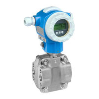
KA01024P/00/EN/18.16
71336239
|
Products |
Solutions |
Services |
Brief Operating Instructions
Deltabar S
PMD75, FMD77, FMD78
Differential pressure measurement
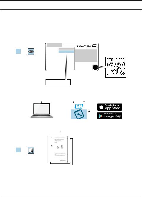
These Instructions are Brief Operating Instructions; they are not a substitute for the Operating Instructions pertaining to the device.
Detailed information about the device can be found in the Operating Instructions and the other documentation:
Available for all device versions via:
–Internet: www.endress.com/deviceviewer
–Smart phone/tablet: Endress+Hauser Operations App
Deltabar S FOUNDATION Fieldbus
|
Order code: |
XXXXX-XXXXXX |
|
|
1. |
Ser. no.: |
XXXXXXXXXXXX |
|
Serial number |
|||||||||||||||||||||||||
|
2. |
www.endress.com/deviceviewer |
Endress+Hauser |
|||||||||||||||||||||||
|
Operations App |
|||||||||||||||||||||||||
3.
A0023555
|
Deltabar S FOUNDATION Fieldbus |
Table of contents |
Table of contents
1 Document information . . . . . . . . . . . . . . . . . . . . . . . . . . . . . . . . . . . . . . . . . . . . . . . . . . . . . . . . . 4
1.1 Document function . . . . . . . . . . . . . . . . . . . . . . . . . . . . . . . . . . . . . . . . . . . . . . . . . . . . . . . . . . . . . . . . . . . . . . . . . . . . . . . . . . 4 1.2 Symbols used . . . . . . . . . . . . . . . . . . . . . . . . . . . . . . . . . . . . . . . . . . . . . . . . . . . . . . . . . . . . . . . . . . . . . . . . . . . . . . . . . . . . . . . 4 1.3 Registered trademarks . . . . . . . . . . . . . . . . . . . . . . . . . . . . . . . . . . . . . . . . . . . . . . . . . . . . . . . . . . . . . . . . . . . . . . . . . . . . . . . 6 1.4 Terms and abbreviations . . . . . . . . . . . . . . . . . . . . . . . . . . . . . . . . . . . . . . . . . . . . . . . . . . . . . . . . . . . . . . . . . . . . . . . . . . . . . . 7 1.5 Turn down calculation . . . . . . . . . . . . . . . . . . . . . . . . . . . . . . . . . . . . . . . . . . . . . . . . . . . . . . . . . . . . . . . . . . . . . . . . . . . . . . . . 8
2 Basic safety instructions . . . . . . . . . . . . . . . . . . . . . . . . . . . . . . . . . . . . . . . . . . . . . . . . . . . . . . . . 9
2.1 Requirements concerning the staff . . . . . . . . . . . . . . . . . . . . . . . . . . . . . . . . . . . . . . . . . . . . . . . . . . . . . . . . . . . . . . . . . . . . . 9 2.2 Designated use . . . . . . . . . . . . . . . . . . . . . . . . . . . . . . . . . . . . . . . . . . . . . . . . . . . . . . . . . . . . . . . . . . . . . . . . . . . . . . . . . . . . . . 9 2.3 Workplace safety . . . . . . . . . . . . . . . . . . . . . . . . . . . . . . . . . . . . . . . . . . . . . . . . . . . . . . . . . . . . . . . . . . . . . . . . . . . . . . . . . . . . 9 2.4 Operational safety . . . . . . . . . . . . . . . . . . . . . . . . . . . . . . . . . . . . . . . . . . . . . . . . . . . . . . . . . . . . . . . . . . . . . . . . . . . . . . . . . . . 9 2.5 Hazardous area . . . . . . . . . . . . . . . . . . . . . . . . . . . . . . . . . . . . . . . . . . . . . . . . . . . . . . . . . . . . . . . . . . . . . . . . . . . . . . . . . . . . 10 2.6 Product safety . . . . . . . . . . . . . . . . . . . . . . . . . . . . . . . . . . . . . . . . . . . . . . . . . . . . . . . . . . . . . . . . . . . . . . . . . . . . . . . . . . . . . . 10
3 Identification. . . . . . . . . . . . . . . . . . . . . . . . . . . . . . . . . . . . . . . . . . . . . . . . . . . . . . . . . . . . . . . . .10
3.1 Product identification . . . . . . . . . . . . . . . . . . . . . . . . . . . . . . . . . . . . . . . . . . . . . . . . . . . . . . . . . . . . . . . . . . . . . . . . . . . . . . . 10 3.2 Device designation . . . . . . . . . . . . . . . . . . . . . . . . . . . . . . . . . . . . . . . . . . . . . . . . . . . . . . . . . . . . . . . . . . . . . . . . . . . . . . . . . . 11 3.3 Scope of delivery . . . . . . . . . . . . . . . . . . . . . . . . . . . . . . . . . . . . . . . . . . . . . . . . . . . . . . . . . . . . . . . . . . . . . . . . . . . . . . . . . . . 11 3.4 CE mark, Declaration of Conformity . . . . . . . . . . . . . . . . . . . . . . . . . . . . . . . . . . . . . . . . . . . . . . . . . . . . . . . . . . . . . . . . . . . 12 3.5 Registered trademarks . . . . . . . . . . . . . . . . . . . . . . . . . . . . . . . . . . . . . . . . . . . . . . . . . . . . . . . . . . . . . . . . . . . . . . . . . . . . . . 12
4 Installation . . . . . . . . . . . . . . . . . . . . . . . . . . . . . . . . . . . . . . . . . . . . . . . . . . . . . . . . . . . . . . . . . .13
4.1 Incoming acceptance and storage . . . . . . . . . . . . . . . . . . . . . . . . . . . . . . . . . . . . . . . . . . . . . . . . . . . . . . . . . . . . . . . . . . . . . 13 4.2 Installation conditions . . . . . . . . . . . . . . . . . . . . . . . . . . . . . . . . . . . . . . . . . . . . . . . . . . . . . . . . . . . . . . . . . . . . . . . . . . . . . . . 14 4.3 Installation instructions . . . . . . . . . . . . . . . . . . . . . . . . . . . . . . . . . . . . . . . . . . . . . . . . . . . . . . . . . . . . . . . . . . . . . . . . . . . . . 14 4.4 Post-installation check . . . . . . . . . . . . . . . . . . . . . . . . . . . . . . . . . . . . . . . . . . . . . . . . . . . . . . . . . . . . . . . . . . . . . . . . . . . . . . 21
5 Wiring . . . . . . . . . . . . . . . . . . . . . . . . . . . . . . . . . . . . . . . . . . . . . . . . . . . . . . . . . . . . . . . . . . . . . .22
5.1 Connecting the device . . . . . . . . . . . . . . . . . . . . . . . . . . . . . . . . . . . . . . . . . . . . . . . . . . . . . . . . . . . . . . . . . . . . . . . . . . . . . . . 22 5.2 Connecting the measuring unit . . . . . . . . . . . . . . . . . . . . . . . . . . . . . . . . . . . . . . . . . . . . . . . . . . . . . . . . . . . . . . . . . . . . . . . 23 5.3 Overvoltage protection (optional) . . . . . . . . . . . . . . . . . . . . . . . . . . . . . . . . . . . . . . . . . . . . . . . . . . . . . . . . . . . . . . . . . . . . . 24 5.4 Post-connection check . . . . . . . . . . . . . . . . . . . . . . . . . . . . . . . . . . . . . . . . . . . . . . . . . . . . . . . . . . . . . . . . . . . . . . . . . . . . . . 24
6 Operation. . . . . . . . . . . . . . . . . . . . . . . . . . . . . . . . . . . . . . . . . . . . . . . . . . . . . . . . . . . . . . . . . . . .25
6.1 Onsite display (optional) . . . . . . . . . . . . . . . . . . . . . . . . . . . . . . . . . . . . . . . . . . . . . . . . . . . . . . . . . . . . . . . . . . . . . . . . . . . . . 25 6.2 Operating elements . . . . . . . . . . . . . . . . . . . . . . . . . . . . . . . . . . . . . . . . . . . . . . . . . . . . . . . . . . . . . . . . . . . . . . . . . . . . . . . . . 27 6.3 FOUNDATION Fieldbus interface . . . . . . . . . . . . . . . . . . . . . . . . . . . . . . . . . . . . . . . . . . . . . . . . . . . . . . . . . . . . . . . . . . . . . 30 6.4 Local operation – onsite display connected . . . . . . . . . . . . . . . . . . . . . . . . . . . . . . . . . . . . . . . . . . . . . . . . . . . . . . . . . . . . . 31 6.5 HistoROM®/M-DAT (optional) . . . . . . . . . . . . . . . . . . . . . . . . . . . . . . . . . . . . . . . . . . . . . . . . . . . . . . . . . . . . . . . . . . . . . . . 35 6.6 FieldCare . . . . . . . . . . . . . . . . . . . . . . . . . . . . . . . . . . . . . . . . . . . . . . . . . . . . . . . . . . . . . . . . . . . . . . . . . . . . . . . . . . . . . . . . . . 35 6.7 Locking/unlocking operation . . . . . . . . . . . . . . . . . . . . . . . . . . . . . . . . . . . . . . . . . . . . . . . . . . . . . . . . . . . . . . . . . . . . . . . . . 35 6.8 Simulation . . . . . . . . . . . . . . . . . . . . . . . . . . . . . . . . . . . . . . . . . . . . . . . . . . . . . . . . . . . . . . . . . . . . . . . . . . . . . . . . . . . . . . . . . 36 6.9 Factory setting (reset) . . . . . . . . . . . . . . . . . . . . . . . . . . . . . . . . . . . . . . . . . . . . . . . . . . . . . . . . . . . . . . . . . . . . . . . . . . . . . . . 36
7 Commissioning . . . . . . . . . . . . . . . . . . . . . . . . . . . . . . . . . . . . . . . . . . . . . . . . . . . . . . . . . . . . . . .36
7.1 Configuring messages . . . . . . . . . . . . . . . . . . . . . . . . . . . . . . . . . . . . . . . . . . . . . . . . . . . . . . . . . . . . . . . . . . . . . . . . . . . . . . . 36 7.2 Function check . . . . . . . . . . . . . . . . . . . . . . . . . . . . . . . . . . . . . . . . . . . . . . . . . . . . . . . . . . . . . . . . . . . . . . . . . . . . . . . . . . . . . 36 7.3 Commissioning via an FF configuration program . . . . . . . . . . . . . . . . . . . . . . . . . . . . . . . . . . . . . . . . . . . . . . . . . . . . . . . . 37 7.4 Selecting the language and measuring mode . . . . . . . . . . . . . . . . . . . . . . . . . . . . . . . . . . . . . . . . . . . . . . . . . . . . . . . . . . . 37 7.5 Position adjustment . . . . . . . . . . . . . . . . . . . . . . . . . . . . . . . . . . . . . . . . . . . . . . . . . . . . . . . . . . . . . . . . . . . . . . . . . . . . . . . . . 37 7.6 Flow measurement . . . . . . . . . . . . . . . . . . . . . . . . . . . . . . . . . . . . . . . . . . . . . . . . . . . . . . . . . . . . . . . . . . . . . . . . . . . . . . . . . 38 7.7 Level measurement . . . . . . . . . . . . . . . . . . . . . . . . . . . . . . . . . . . . . . . . . . . . . . . . . . . . . . . . . . . . . . . . . . . . . . . . . . . . . . . . . 42 7.8 Differential pressure measurement . . . . . . . . . . . . . . . . . . . . . . . . . . . . . . . . . . . . . . . . . . . . . . . . . . . . . . . . . . . . . . . . . . . . 48 7.9 Scaling the OUT parameter . . . . . . . . . . . . . . . . . . . . . . . . . . . . . . . . . . . . . . . . . . . . . . . . . . . . . . . . . . . . . . . . . . . . . . . . . . 51
|
Document information |
Deltabar S FOUNDATION Fieldbus |
1 Document information
1.1Document function
These Operating Instructions contain all the information that is required in various phases of the life cycle of the device: from product identification, incoming acceptance and storage, to mounting, connection, operation and commissioning through to troubleshooting, maintenance and disposal.
1.2Symbols used
1.2.1 Safety symbols
|
Symbol |
Meaning |
|||||
|
DANGER! |
||||||
|
DANGER |
||||||
|
This symbol alerts you to a dangerous situation. Failure to avoid this situation will result in |
||||||
|
A0011189-DE |
seriousor fatal injury. |
|||||
|
WARNING! |
||||||
|
WARNING |
||||||
|
This symbol alerts you to a dangerous situation. Failure to avoid this situation can result in |
||||||
|
A0011190-DE |
seriousor fatal injury. |
|||||
|
CAUTION! |
||||||
|
CAUTION |
This symbol alerts you to a dangerous situation. Failure to avoid this situation can result in |
|||||
|
A0011191-DE |
minoror medium injury. |
|||||
|
NOTICE! |
||||||
|
NOTICE |
||||||
|
This symbol contains information on procedures and other facts which do not result in |
||||||
|
A0011192-DE |
personalinjury. |
|||||
1.2.2 Electrical symbols
|
Symbol |
Meaning |
Symbol |
Meaning |
||
|
Direct current |
Alternating current |
||||
|
Direct current and alternating current |
Ground connection |
||||
|
) |
A grounded terminal which, as far as |
||||
|
the operator is concerned, is grounded |
|||||
|
via a grounding system. |
|||||
|
Protective ground connection |
Equipotential connection |
||||
|
A terminal which must be connected to |
A connection that has to be connected |
||||
|
ground prior to establishing any other |
to the plant grounding system: This may |
||||
|
connections. |
be a potential equalization line or a star |
||||
|
grounding system depending on |
|||||
|
national or company codes of practice. |
|||||

Deltabar S FOUNDATION Fieldbus Document information
1.2.3 Tool symbols
A0011221
Hexagon wrench
A0011222
1.2.4 Symbols for certain types of information
Symbol Meaning
Permitted
Indicates procedures, processes or actions that are permitted.
A0011182
Forbidden
Indicates procedures, processes or actions that are forbidden.
A0011184
Tip
Indicates additional information.
A0011193
Reference to documentation
A0015482
Reference to page
A0015484
Reference to graphic
A0015487
Series of steps
1. , 2. , 3. …
A0031595
Result of a sequence of actions
A0018343
Visual inspection
A0015502
Document information Deltabar S FOUNDATION Fieldbus
1.2.5 Symbols in graphics
|
Symbol |
Meaning |
||||||
|
1, 2, 3, 4, … |
Item numbers |
||||||
|
Series of steps |
|||||||
|
1. |
, |
2. |
, |
3. |
… |
||
|
A0031595 |
|||||||
|
A, B, C, D, … |
Views |
||||||
1.2.6 Symbols at the device
Symbol Meaning
Safety instructions
Observe the safety instructions contained in the associated Operating Instructions.
A0019159
1.3Registered trademarks
KALREZ, VITON, TEFLON
Registered trademarks of E.I. Du Pont de Nemours & Co., Wilmington, USA
TRI-CLAMP
Registered trademark of Ladish & Co., Inc., Kenosha, USA
FOUNDATIONTM Fieldbus
Registered trademark of the FieldComm Group, Austin, USA
GORE-TEX®
Registered trademarks of W.L. Gore & Associates, Inc., USA

|
Deltabar S FOUNDATION Fieldbus |
Document information |
1.4Terms and abbreviations
|
1 |
|||||
|
2 |
|||||
|
3 |
|||||
|
4 |
|||||
|
p |
|||||
|
0 |
|||||
|
LRL |
LRV |
URV |
URL |
MWP |
OPL |
|
A0029505 |
|
Position |
Term/Abbreviation |
Explanation |
|
1 |
OPL |
The OPL (over pressure limit = sensor overload limit) for the sensors depends |
|
on the lowest-rated element, with regard to pressure, of the selected |
||
|
components, i.e. the process connection must be taken into consideration in |
||
|
addition to the measuring cell. Also observe pressure-temperature |
||
|
dependency. For the relevant standards and additional notes, see technical |
||
|
information. |
||
|
The OPL may be applied for a limited time period. |
||
|
2 |
MWP |
The MWP (maximum working pressure) for the sensors depends on the |
|
lowest-rated element, with regard to pressure, of the selected components, |
||
|
i.e. the process connection has to be taken into consideration in addition to |
||
|
the measuring cell. Also observe pressure-temperature dependency. For the |
||
|
relevant standards and additional notes, see technical information. |
||
|
The MWP may be applied for an unlimited time. |
||
|
3 |
Maximum sensor |
Range between LRL and URL |
|
measuring range |
This span is the maximum calibratable/adjustable measuring span. |
|

|
Document information |
Deltabar S FOUNDATION Fieldbus |
|
|
Position |
Term/Abbreviation |
Explanation |
|
4 |
Calibrated/Adjusted |
Range between LRV and URV |
|
measuring span |
Factory setting: 0…URL |
|
|
Other calibrated spans can be ordered with customised settings. |
||
|
p |
— |
Pressure |
|
— |
LRL |
Lower range limit |
|
— |
URL |
Upper range limit |
|
— |
LRV |
Lower range value |
|
— |
URV |
Upper range value |
|
— |
TD |
Turn down |
1.5Turn down calculation
|
1 = 2 |
3 |
|||||
|
LRL LRV |
URV |
URL |
||||
A0029545
Fig. 1:
1Calibrated/Adjusted measuring span
2Zero-based span
3Upper range limit
|
Example |
||||||
|
• Sensor: 10 bar (150 psi) |
• Calibrated/Adjusted measuring span: 0…5 bar |
|||||
|
• Upper range limit (URL) = 10 bar (150 psi) |
(0…75 psi) |
|||||
|
• Lower range value (LRV) = 0 bar |
||||||
|
Turn down (TD): |
• Upper range value (URV) = 5 bar (75 psi) |
|||||
|
TD |
= |
URL |
||||
|
|URV |
— |
LRV| |
||||
|
TD |
= |
10 bar (150 psi) |
= 2 |
|||
|
|5 bar (75 psi) |
— |
0 bar (0 psi)| |
||||
|
In this example, the TD is thus 2:1. |
||||||
|
This span is based on the zero point. |
||||||
|
Deltabar S FOUNDATION Fieldbus |
Basic safety instructions |
2 Basic safety instructions
2.1Requirements concerning the staff
The personnel for installation, commissioning, diagnostics and maintenance must fulfill the following requirements:
•Trained, qualified specialists: must have a relevant qualification for this specific function and task
•Are authorized by the plant owner/operator
•Are familiar with federal/national regulations
•Before beginning work, the specialist staff must have read and understood the instructions in the Operating Instructions and supplementary documentation as well as in the certificates (depending on the application)
•Following instructions and basic conditions
The operating personnel must fulfill the following requirements:
•Being instructed and authorized according to the requirements of the task by the facility’s owner-operator
•Following the instructions in these Operating Instructions
2.2Designated use
The Deltabar S is a differential pressure transmitter for measuring differential pressure, flow and level.
2.2.1 Incorrect use
The manufacturer is not liable for damage caused by improper or non-designated use. Verification for borderline cases:
For special fluids and fluids for cleaning, Endress+Hauser is glad to provide assistance in verifying the corrosion resistance of fluid-wetted materials, but does not accept any warranty or liability.
2.3Workplace safety
For work on and with the device:
•Wear the required personal protective equipment according to federal/national regulations.
•Switch off the supply voltage before connecting the device.
2.4Operational safety
Risk of injury!
Operate the device in proper technical condition and fail-safe condition only.
The operator is responsible for interference-free operation of the device.
|
Identification |
Deltabar S FOUNDATION Fieldbus |
Conversions to the device
Unauthorized modifications to the device are not permitted and can lead to unforeseeable dangers:
If, despite this, modifications are required, consult with Endress+Hauser.
Repair
To ensure continued operational safety and reliability,
Carry out repairs on the device only if they are expressly permitted.
Observe federal/national regulations pertaining to repair of an electrical device.
Use original spare parts and accessories from Endress+Hauser only.
2.5Hazardous area
To eliminate a danger for persons or for the facility when the device is used in the hazardous area (e.g. explosion protection, pressure vessel safety):
•Based on the nameplate, check whether the ordered device is permitted for the intended use in the hazardous area.
•Observe the specifications in the separate supplementary documentation that is an integral part of these Instructions.
2.6Product safety
This measuring device is designed in accordance with good engineering practice to meet state-of-the- art safety requirements, has been tested, and left the factory in a condition in which they are safe to operate. It fulfills general safety requirements and legal requirements. It also conforms to the EC directives listed in the device-specific EC declaration of conformity. Endress+Hauser confirms this fact by applying the CE mark.
3 Identification
3.1Product identification
The following options are available for identification of the measuring device:
•Nameplate specifications
•Order code with breakdown of the device features on the delivery note
•Enter serial numbers from nameplates in W@M Device Viewer (www.endress.com/deviceviewer): All information about the measuring device is displayed.
For an overview of the technical documentation provided, enter the serial number from the nameplates in the W@M Device Viewer (www.endress.com/deviceviewer).
|
Deltabar S FOUNDATION Fieldbus |
Identification |
3.2Device designation
3.2.1 Nameplates
•The MWP (maximum working pressure) is specified on the nameplate. This value refers to a reference temperature of +20 °C (68°F) and may be applied to the device for an unlimited time. Observe temperature dependency of the MWP. The pressure values permitted at higher temperatures can be found in the standards EN 1092-1: 2001 Tab. 18 (With regard to their stability-temperature property, the materials 1.4435 and 1.4404 are grouped together under 13EO in EN 1092-1 Tab. 18. The chemical composition of the two materials can be identical.), ASME B 16.5a – 1998 Tab. 2-2.2 F316, ASME B 16.5a – 1998 Tab. 2.3.8 N10276, JIS B 2220.
•For PMD75, the MWP applies for the temperature ranges specified in the Technical Information TI00382P in the «Ambient temperature range» and «Process temperature limits» sections.
•The test pressure corresponds to the over pressure limit (OPL) of the device = MWP x 1.5.
•The Pressure Equipment Directive (2014/68/EU) uses the abbreviation «PS».
The abbreviation «PS» corresponds to the MWP (maximum working pressure) of the measuring device.
3.2.2 Identifying the sensor type
See parameter «Sensor Meas.Type» in Operating Instruction BA00303P.
3.3Scope of delivery
The scope of delivery comprises:
•Deltabar S differential pressure transmitter
•For PMD75 with side flanges made of AISI 316L or C22.8: additionally 2 vent valves, AISI 316L
•PMD75 with side flanges made of AISI 316L or C22.8 and side vent: additionally 4 locking screws, AISI 316L
•For devices with the «HistoROM/M-DAT» option: CD-ROM with Endress+Hauser operating program
•Optional accessories
Documentation supplied:
•Operating Instructions BA00301P and BA00303P are available via the Internet.See: www.endress.com Download.
•Brief Operating Instructions KA01024P
•Fold-out brochure KA00252P
•Final inspection report
•Additional Safety Instructions with ATEX, IECEx and NEPSI devices
•Optional: factory calibration form, test certificates
|
Identification |
Deltabar S FOUNDATION Fieldbus |
3.4CE mark, Declaration of Conformity
The devices are designed to meet state-of-the-art safety requirements, have been tested and left the factory in a condition in which they are safe to operate. The devices comply with the applicable standards and regulations as listed in the EC Declaration of Conformity and thus comply with the statutory requirements of the EC Directives. Endress+Hauser confirms the conformity of the device by affixing to it the CE mark.
3.5Registered trademarks
KALREZ, VITON, TEFLON
Registered trademarks of E.I. Du Pont de Nemours & Co., Wilmington, USA
TRI-CLAMP
Registered trademark of Ladish & Co., Inc., Kenosha, USA
FOUNDATIONTM Fieldbus
Registered trademark of the Fieldbus Foundation Austin, Texas, USA

|
Deltabar S FOUNDATION Fieldbus |
Installation |
4 Installation
NOTICE
Incorrect handling!
Damage of the device!
Disassembly of the screws with item number (1) is not permissible under any circumstances and will result in loss of warranty.
1
A0025336
4.1Incoming acceptance and storage
4.1.1 Incoming acceptance
• Check the packaging and the contents for damage.
• Check the shipment, make sure nothing is missing and that the scope of supply matches your order.
4.1.2 Transport
! WARNING
Incorrect transport
Housing and diaphragm may be damaged and and there is a risk of injury!
Transport the measuring device to the measuring point in its original packaging or by the process connection (with secure transport protection for the diaphragm).
Follow the safety instructions and transport conditions for devices of more than 18 kg (39.69 lbs).
Do not use capillaries as a carrying aid for the diaphragm seals.
4.1.3 Storage
The device must be stored in a dry, clean area and protected against impact (EN 837-2). Storage temperature range:
•–40 to +90°C (–40 to +194 °F)
•Onsite display: –40 to +85°C (–40 to +185°F)
•Separate housing: –40 to +60°C (–40 to +140°F)
|
Installation |
Deltabar S FOUNDATION Fieldbus |
4.2Installation conditions
4.2.1 Dimensions
For dimensions, please refer to the Technical Information for Deltabar S TI00382P, «Mechanical construction» section.
4.3Installation instructions
•Due to the orientation of the Deltabar S, there may be a shift in the measured value, i.e. when the container is empty or partially full, the measured value does not display zero. You can correct this zero point shift using the «Zero» key on the electronic insert or externally on the device or via the onsite display. ä 27, Section 6.2.1 «Position of the operating elements»,
ä 29, Section 6.2.3 «Function of the operating elements – onsite display connected» and
ä 37, Section 7.5 «Position adjustment»..
•For FMD77 and FMD78, please refer to Section 4.3.4 «Installation instructions for devices with diaphragm seals (FMD78)», ä 16.
•General recommendations for routing the pressure piping can be found in DIN 19210 «Methods for measurement of fluid flow; differential piping for flow measurement devices» or the corresponding national or international standards.
•Using a three-way or five-way valve manifold allows for easy commissioning, installation and maintenance without interrupting the process.
•When routing the pressure piping outdoors, ensure that sufficient antifreeze protection is used, e.g. by using pipe heat tracing.
•Install the pressure piping with a monotonic gradient of at least 10%.
•To ensure optimal readability of the onsite display, it is possible to rotate the housing up to 380°. ä 20, Section 4.3.9 «Rotating the housing».
•Endress+Hauser offers a mounting bracket for installing on pipes or walls.
ä 18, Section 4.3.7 «Wall and pipe-mounting (optional)».
4.3.1 Installation for flow measurement
Flow measurement in gases with PMD75
•Mount the Deltabar S above the measuring point so that the condensate can run off into the process piping.
Flow measurement in steam with PMD75
•Mount the Deltabar S below the measuring point.
•Mount the condensate traps at the same level as the tapping points and at the same distance to the Deltabar S.
•Prior to commissioning, fill the pressure piping to the level of the condensate traps.
Flow measurement in liquids with PMD75
•Mount the Deltabar S below the measuring point so that the pressure piping is always filled with liquid and gas bubbles can run back into the process piping.
|
Deltabar S FOUNDATION Fieldbus |
Installation |
•When measuring in media with solid parts, such as dirty liquids, installing separators and drain valves is useful for capturing and removing sediment.
4.3.2 Installation for level measurement
Level measurement in an open container with PMD75
•Mount the Deltabar S below the lower measuring connection so that the pressure piping is always filled with liquid.
•The negative side is open to atmospheric pressure.
•When measuring in media with solid parts, such as dirty liquids, installing separators and drain valves is useful for capturing and removing sediment.
Level measurement in an open container with FMD77
•Mount the Deltabar S directly on the container. ä 18, Section 4.3.5 «Seal for flange mounting».
•The negative side is open to atmospheric pressure.
Level measurement in a closed container with PMD75
•Mount the Deltabar S below the lower measuring connection so that the pressure piping is always filled with liquid.
•Always connect the impulse piping of negative side above the maximum level.
•When measuring in media with solid parts, such as dirty liquids, installing separators and drain valves is useful for capturing and removing sediment.
Level measurement in a closed container with FMD77
•Mount the Deltabar S directly on the container. ä 18, Section 4.3.5 «Seal for flange mounting».
•Always connect the impulse piping of negative side above the maximum level.
•When measuring in media with solid parts, such as dirty liquids, installing separators and drain valves is useful for capturing and removing sediment.
Level measurement in a closed container with FMD78
•Mount the Deltabar S below the lower diaphragm seal. ä 16, Section 4.3.4 «Installation instructions for devices with diaphragm seals (FMD78)».
•The ambient temperature should be the same for both capillaries.
Level measurement is only ensured between the upper edge of the lower diaphragm seal and the lower edge of the upper diaphragm seal.
Level measurement in a closed container with superimposed steam with PMD75
•Mount the Deltabar S below the lower measuring connection so that the pressure piping is always filled with liquid.
•Always connect the impulse piping of negative side above the maximum level.

|
Installation |
Deltabar S FOUNDATION Fieldbus |
•A condensate trap ensures constant pressure on the negative side.
•When measuring in media with solid parts, such as dirty liquids, installing separators and drain valves is useful for capturing and removing sediment.
Level measurement in a closed container with superimposed steam with FMD77
•Mount the Deltabar S directly on the container. ä 18, Section 4.3.5 «Seal for flange mounting».
•Always connect the impulse piping of negative side above the maximum level.
•A condensate trap ensures constant pressure on the negative side.
•When measuring in media with solid parts, such as dirty liquids, installing separators and drain valves is useful for capturing and removing sediment.
4.3.3 Installation for differential pressure measurement
Differential pressure measurement in gases and steam with PMD75
•Mount the Deltabar S above the measuring point so that the condensate can run off into the process piping.
Differential pressure measurement in liquids with PMD75
•Mount the Deltabar S below the measuring point so that the pressure piping is always filled with liquid and gas bubbles can run back into the process piping.
•When measuring in media with solid parts, such as dirty liquids, installing separators and drain valves is useful for capturing and removing sediment.
Differential pressure measurement in gases, steam and liquids with FMD78
•Mount the diaphragm seal with capillaries at the top or on the side on the piping.
•For vacuum applications: mount the Deltabar S below the measuring point. ä 17, Section 4.3.4, «Vacuum application (FMD78)».
•The ambient temperature should be the same for both capillaries.
4.3.4 Installation instructions for devices with diaphragm seals (FMD78)
•Please note that the hydrostatic pressure of the liquid columns in the capillaries can cause zero point shift. The zero point shift can be corrected.
•Do not clean or touch the process isolating diaphragm of the diaphragm seal with hard or pointed objects.
•Do not remove process isolating diaphragm protection until shortly before installation.
NOTICE
Improper handling!
Damage to the device!
A diaphragm seal and the pressure transmitter together form a closed, oil-filled calibrated system. The fill fluid hole is sealed and may not be opened.
 Loading…