
-
Contents
-
Table of Contents
-
Troubleshooting
-
Bookmarks
Related Manuals for Basler DECS-100
Summary of Contents for Basler DECS-100
-
Page 1
INSTRUCTION MANUAL DIGITAL EXCITATION CONTROL SYSTEM DECS-100 Publication: 9287500991 Revision: K 05/11… -
Page 3
DECS-100. NOTE Be sure that the DECS-100 is hard-wired to earth ground with no smaller than 12 AWG copp er wire atta ched to the grou nd termin al o n the rea r of the unit ca se. -
Page 4
May 2011 CONFIDENTIAL INFORMATION of Basler Electric, Highland Illinois, USA. It is loaned for confidential use, subject to return on request, and with the mutual understanding that it will not be used in any manner detrimental to the interest of Basler Electric. -
Page 5
REVISION HISTORY The following information provides a historical summary of the changes made to the DECS-100 hardware, firmware, and software. The corresponding revisions made to this instruction manual (9287500991) are also summarized. Revisions are listed in chronological order. Hardware Version and Date… -
Page 6
1 to 300 seconds throughout manual • Corrected figure number references in Sections 5 and 6 E, 03/04 • Added Operating Power Considerations During DECS-100 Programming Installation, Preliminary Setup Section 4, • Added caution box regarding application of operating power during DECS- BESTCOMS for Windows®… -
Page 7
• Revised voltage matching description to cover Maintain and Revert modes • Corrected the hole drilling diameter shown in Figure 4-2 • Added illustration/description for using the ICRM-7 with the DECS-100 BESTCOMS Software for the Palm® OS Platform • Removed Section 6,… -
Page 8
This page intentionally left blank. DECS-100 Introduction 9287500991 Rev K… -
Page 9
Section 1 General Information ………………..1-1 Section 2 Human-Machine Interface ………………2-1 Section 3 Functional Description ………………..3-1 Section 4 Installation ……………………. 4-1 Section 5 BESTCOMS Software ………………..5-1 Section 6 Maintenance and Troubleshooting…………….6-1 9287500991 Rev K DECS-100 Introduction… -
Page 10
This page intentionally left blank. viii DECS-100 Introduction 9287500991 Rev K… -
Page 11: Table Of Contents
Metering (BESTCOMS) ……………………1-5 Environment ……………………….1-6 Type Tests ……………………….1-6 Physical ………………………… 1-6 Agency Recognition ……………………… 1-6 CE Compliance ……………………..1-6 Figures Figure 1-1. DECS-100 Style Chart ………………….1-1 Figure 1-2. Typical V/Hz Curves …………………… 1-4 9287500991 Rev K DECS-100 General Information…
-
Page 12
This page intentionally left blank. DECS-100 General Information 9287500991 Rev K… -
Page 13: Section 1 • General Information
The model number, together with the style number, describe the options included in a specific device, and appear on a label affixed to the rear panel. Upon receipt of a DECS-100, be sure to check the style number against the requisition and the packing list to ensure that they agree.
-
Page 14: Specifications
Style Number Example For example, a DECS-100 with a style number of A15 would have the following characteristics and operating features. A ——- No var or power factor control 1 ——— Voltage matching 5 ——— 5 ampere current sensing SPECIFICATIONS DECS-100 specifications and qualifications are listed in the following paragraphs.
-
Page 15: Accessory Input
Baud: 4800 Data Bits: Parity: None Stop Bit: Contact Input Circuits Type: Dry contacts Interrogation Voltage: 13 Vdc (supplied by DECS-100) Terminal Assignments for Standard Functions Raise: 6U, 7 Lower: 6D, 7 Var/PF Enable: 52J, 52K Parallel Control: 52L, 52M…
-
Page 16: Fcr (Manual) Operating Mode
Pickup Range: 0 to 250 Vdc Time Delay: 10 s (fixed) Generator Overvoltage Protection Pickup Range: 100 to 120% of system voltage setting Increment: 1.0% Alarm Time Delay Range: 0 to 10 s Increment: DECS-100 General Information 9287500991 Rev K…
-
Page 17: Overexcitation Limiter
Range: 0 to 20 A Accuracy: ±0.5% (at 25°C) Bus Voltage Range: 10 V to 79 kV Accuracy: ±0.5% (at 25°C) Auxiliary DC Input Range: –3 V to +3 V Accuracy: ±0.5% (at 25°C) 9287500991 Rev K DECS-100 General Information…
-
Page 18: Environment
Radio Frequency–Conducted: IEC 1000-4-6/EN 61000-4-6, Level A Power Frequency–Magnetic: IEC 1000-4-8/EN 61000-4-8, Level A Dielectric: IEC 255 Surge Immunity: IEC 1000-4-5/EN 61000-4-5, Level B Voltage Dips, Interruptions, and Variations Immunity: IEC 1000-4-11/EN 61000-4-11, Level C DECS-100 General Information 9287500991 Rev K…
-
Page 19: Table Of Contents
Var/P.F. Mode Active ……………………. 2-2 Manual Mode Active ……………………… 2-2 Underfrequency Active ……………………2-2 COMMUNICATION PORT ……………………2-2 Figures Figure 2-1. DECS-100 Front Panel Indicators ………………. 2-1 Figure 2-2. DECS-100 Communication Port Location…………….2-2 9287500991 Rev K DECS-100 Human-Machine Interface…
-
Page 20
This page intentionally left blank. DECS-100 Human-Machine Interface 9287500991 Rev K… -
Page 21
The DECS-100 human-machine interface (HMI) consists of front panel indicators and a rear-panel communication port. FRONT PANEL INDICATORS DECS-100 front panel indicators consist of eight red LEDs. The indicators are shown in Figure 2-1 and described in the following paragraphs. Figure 2-1. DECS-100 Front Panel Indicators… -
Page 22
DECS-100 is powered up following an underexcitation limiting shutdown. Var/P.F. Mode Active This LED lights to indicate that the DECS-100 is operating in the optional Var or Power Factor mode of control. Var/Power Factor control is enabled through BESTCOMS software and when the 52J/K contact input is open. -
Page 23
Field Overvoltage (Overexcitation Shutdown) …………….3-5 Limiters …………………………. 3-6 Overexcitation Limiting ……………………3-6 Underexcitation Limiting ……………………. 3-6 Soft Start ……………………….. 3-6 Voltage Matching (Optional) ………………….. 3-6 Figures Figure 3-1. Simplified DECS-100 Block Diagram ………………3-1 9287500991 Rev K DECS-100 Functional Description… -
Page 24
This page intentionally left blank. DECS-100 Functional Description 9287500991 Rev K… -
Page 25
SECTION 3 • FUNCTIONAL DESCRIPTION INTRODUCTION This section describes how the DECS-100 functions and explains its operating features. To ease understanding, DECS-100 functions are illustrated in the block diagram of Figure 3-1. A detailed DECS-100 Function description of each function block is provided in the paragraphs under the heading of… -
Page 26
Closing a contact across terminals 52J and 52K disables var/power factor control. An open contact enables the DECS-100 to control the generator reactive power in either the var or the power factor mode. The contact has no effect when this function is not enabled in the software. For more information, see… -
Page 27
If the Voltage Matching option is enabled in the software, closing a contact across terminals VM and VMC causes the DECS-100 to operate in the voltage matching mode. An open contact disables voltage matching. Voltage matching is also disabled when either the 52J/K or 52L/M inputs are open. -
Page 28
Var Control Mode (Optional) In Var Control mode, the DECS-100 maintains generator vars (volt-amperes, reactive) at a set level when paralleling with an infinite bus. The DECS-100 calculates generator vars by using the sensed generator output voltage and current quantities. -
Page 29
If transfer to Manual is selected and a loss of sensing occurs, the relay output closes, and the DECS-100 transfers to the Manual mode of operation after the adjustable time delay expires. The DECS-100 will remain in this mode of operation until switched via BESTCOMS. -
Page 30
Its drawback is that it may not provide a smooth transition into and out of the limit. If hardware shutdown is enabled, the DECS-100 will be disabled when the time delay expires. When the DECS-100 is powered up following a shutdown triggered by overexcitation limiting, the Overexcitation Limiting indicator will light for five seconds. -
Page 31
DECS-100 voltage sensing inputs) are within the acceptable range, voltage matching can be achieved. The rate at which the DECS-100 matches the generator input level with the bus input level is controlled by a voltage matching speed setting. this setting is adjustable from 1 to 300 seconds in 0.01 second increments. -
Page 32
This page intentionally left blank. DECS-100 Functional Description 9287500991 Rev K… -
Page 33
Figure 4-10. Typical Connections for Station Power Application and Three-Phase Sensing ….4-12 Figure 4-11. Cross-Current (Reactive Differential) Connections …………. 4-13 Figure 4-12. Operating Power Connections for DECS-100 Programming (Input Voltage >120 Vac)..4-14 Tables Table 4-1. Bus Voltage Sensing Terminals ………………..4-5 Table 4-2. -
Page 34
This page intentionally left blank. DECS-100 Installation 9287500991 Rev K… -
Page 35: Section 4 • Installation
MOUNTING The DECS-100 is normally located in the generator conduit box. It is designed for behind the panel mounting and requires a cutout for front panel viewing. Supplied mounting hardware consists of six #12 thread-forming screws that pass through mounting holes in the conduit box and thread into the plastic shell of the DECS-100.
-
Page 36
Figure 4-1. DECS-100 Dimensions DECS-100 Installation 9287500991 Rev K… -
Page 37
Figure 4-2. Cutout and Drilling Dimensions 9287500991 Rev K DECS-100 Installation… -
Page 38: Connections
IBM compatible PCs and hand-held computers. Figure 4-3 shows the terminal connections located on the rear panel of the DECS-100. Except as noted above, connections should be made with minimum wire size of 14 AWG.
-
Page 39: Bus Voltage Sensing Inputs (Optional)
7. The other two terminals are connected to terminals 6U and 6D. This remote adjust switch may be mounted up to 150 feet away from the DECS-100 when using twisted, shielded cable. Only dry, ungrounded switching contacts should be applied to the Raise and Lower contact inputs.
-
Page 40: Parallel Control And Var/Pf Control Inputs
Power input terminals are labeled 3, 4, and 5. Single-phase or three-phase power may be applied. Single- phase power may be applied to any two of the three terminals. The DECS-100 can be powered directly from a variety of sources as long as the DECS-100 input power specifications are followed (see Section 1, General Information, Specifications).
-
Page 41: Communication Port
DECS-100 operating power is derived from a permanent magnet generator (PMG) and three-phase voltage sensing is applied to the DECS-100. Figure 4-7 shows another PMG application but with single-phase voltage sensing. Figure 4-8 shows an application where DECS-100 operating power is derived from the generator output (shunt application) and three-phase voltage sensing is applied to the DECS-100.
-
Page 42
Figure 4-6. Typical Connections for PMG Application with ABC Rotation and Three-Phase Sensing DECS-100 Installation 9287500991 Rev K… -
Page 43
Figure 4-7. Typical Connections for PMG Application with ABC Rotation and Single-Phase Sensing 9287500991 Rev K DECS-100 Installation… -
Page 44
Figure 4-8. Typical Connections for Shunt Application with ABC Rotation and Three-Phase Sensing 4-10 DECS-100 Installation 9287500991 Rev K… -
Page 45
Figure 4-9. Typical Connections for Shunt Application with ABC Rotation and Single-Phase Sensing 9287500991 Rev K DECS-100 Installation 4-11… -
Page 46
Figure 4-10. Typical Connections for Station Power Application and Three-Phase Sensing 4-12 DECS-100 Installation 9287500991 Rev K… -
Page 47: Installation For Ce Compliance
Lethal voltage is present at the rear panel when the unit is energized. Rear panel connections should be made only when the unit is de-energized. 1. Tag and disconnect all wiring to the DECS-100. Be sure to insulate the wire terminals to prevent a short circuit.
-
Page 48: Operating Power Considerations During Decs-100 Programming
7. Connect the rest of the DECS-100 leads using the tagged identification. 8. Start the prime mover/generator and perform the final adjustments at rated speed and load. 9. After the initial startup, the DECS-100 should not require any further adjustments unless there is a change in the system.
-
Page 49
SECTION 5 • BESTCOMS SOFTWARE ………………..5-1 INTRODUCTION………………………. 5-1 INSTALLATION……………………….5-1 Installing BESTCOMS ……………………5-1 Connecting the DECS-100 and PC ………………..5-1 STARTING BESTCOMS ……………………5-1 Establishing Communication ………………….5-2 CHANGING SETTINGS ……………………. 5-2 SENDING AND RECEIVING SETTINGS ………………..5-3 Sending Settings …………………….. -
Page 50
Figure 5-20. Password Dialog Box ………………….5-21 Figure 5-21. Software Uploading Advisory Dialog Box …………….5-22 Figure 5-22. DECS-100 Embedded Program Loader …………….5-22 Figure 5-23. Retrieved DECS-100 Information ………………5-22 Figure 5-24. Settings File Reminder Dialog Box ………………5-23 Figure 5-25. -
Page 51: Section 5 • Bestcoms Software
BESTCOMS. Software within BESTCOMS enables the user to establish proper PID (proportional + integral + derivative) parameters based on a specified generator and/or exciter time constants. Within BESTCOMS, DECS-100 settings can be saved in a computer file and used later to configure other units with the same settings.
-
Page 52: Establishing Communication
Once all desired setting changes have been made on a setting group screen, the settings must be sent to the DECS-100 before viewing other screens. Otherwise, the settings changes will be lost. Settings changes can be sent to the DECS-100 by clicking the SendToDECS button.
-
Page 53: Sending And Receiving Settings
Settings are saved in nonvolatile memory (EEPROM). In the event of a power loss, these are the settings that are active at power up. If settings are changed and sent to the DECS-100, but not sent to EEPROM, the changed settings are lost if DECS-100 operating power is lost. When exiting BESTCOMS or closing communication, you are asked if you want to save the settings to EEPROM.
-
Page 54: Setting Adjustments
This setting field reads and displays the nominal output of the current transformer (CT) that supplies the DECS-100 with B-phase generator line current. This value (1 or 5) must be manually entered for units with a firmware version lower than 1.12.01.
-
Page 55: Startup Tab
Voltage Matching — Speed (sec). This setting determines how quickly the generator voltage is adjusted by the DECS-100 to match the bus voltage. The Speed setting is adjustable from 1 to 300 seconds in 0.01 increments. Voltage Matching – Disable by Contact.
-
Page 56: Control Gain
The voltage matching mode can be Maintain or Revert. When Maintain is selected, the DECS-100 setpoint is maintained at the bus voltage level even after the generator or utility breaker opens. When Revert is selected, the DECS-100 setpoint reverts to its original level when the generator or utility breaker opens.
-
Page 57
Figure 5-9. Control Gain Screen Table 5-1. DECS-100 Stability Range Settings Time Constants Generator Stability Size Generator (T’do) Exciter (Texc) Range SMALL 0.17 0.25 0.33 0.42 0.50 0.58 0.67 0.75 0.83 0.92 1.00 1.08 1.17 1.25 1.33 1.42 1.50 1.58 10.0… -
Page 58: Analysis
VAR/PF — PF Integral Gain KI. This setting adjusts the integral gain and determines the characteristic of the DECS-100 dynamic response to a changed PF setting. PF KI values of 0 to 1,000 may be entered in increments of 0.01.
-
Page 59: Fcr Tab
Figure 5-11 illustrates the settings, sensing values, and alarm signal indicators of the FCR tab. The settings of the FCR tab make it possible to increment and decrement the FCR setpoint of the DECS-100. The sensing values and alarm signal indicators of the FCR tab are also displayed by the other tabs of the Analysis screen.
-
Page 60: Pf Tab
FCR Setpoint field is selected by clicking the adjacent pushbutton. Clicking this button sends the FCR Setpoint value to the DECS-100 and changes the color of the pushbutton from gray to red. Field Current Step Response — Increment of FCR Setpoint (A).
-
Page 61: Var Tab
FCR Setpoint field is selected by clicking the adjacent pushbutton. Clicking this button sends the PF setpoint value to the DECS-100 and changes the color of the pushbutton from gray to red. Power Factor Step Response — Increment of PF Setpoint.
-
Page 62: Protection Settings
Meter Value field or selected by dragging the dial pointer to the desired value. The new value is sent to the DECS-100 by clicking the Send button.
-
Page 63: Protection Tab
The value in this field is adjustable from 0 to 250 Vdc and determines the field voltage level that will cause the DECS-100 to issue an overexcitation limit alarm. When the field voltage increases above the value of this field for 10 seconds, the Overexcitation Shutdown LED on the front panel lights.
-
Page 64: Limiter Tab
The value of current in this field determines the excitation level that will cause the DECS-100 to issue an overexcitation limit alarm. A current level of 0 to 15 A may be entered in 0.01 increments. When the level of field current increases above the value of this field, the Overexcitation Shutdown LED on the front panel lights and the OEL time delay starts timing down.
-
Page 65: Operation Tab
PT ratio. All metering values are updated once each second. When single-phase sensing is used (System Configuration screen, Sensing Voltage) and the DECS-100 sensing voltage terminals (E1, E2, and E3) are connected as shown in Figures 4-7 or 4-9, all of the generator voltage metering values will be identical.
-
Page 66
Power Factor Control (PF) — PF Setpoint. Power Factor setpoint values are adjustable from -0.6 to -1 (1) or 0.6 to +1 in 0.001 increments. The background color of this field is green when the DECS-100 is operating in AVR mode and is regulating the power factor setpoint. -
Page 67: Alarm/Status Tab
External Adjust terminals (6D and 7 to decrease, 6U and 7 to increase) of the DECS-100. For AVR mode, each click of the Raise button increases the voltage setpoint 0.01 volts; each click of the Lower button decreases the voltage setpoint 0.01 volts.
-
Page 68: Pid Data
PID stands for Proportional, Integral, Derivative. The word proportional means that the response of the DECS-100 output is proportional or relative to the amount of change that is observed. Integral means that the DECS-100 output is proportional to the amount of time that a change is observed. Integral action eliminates offset.
-
Page 69: Adding To The Pid List
BESTCOMS software enables you to print a list of DECS-100 settings, save DECS-100 settings to a file, and open a settings file and upload those settings to a DECS-100. A settings file may also be opened and edited within any text editing software.
-
Page 70: Saving Settings Files
A DECS-100 settings file downloaded from a DECS-100 or created within BESTCOMS can be uploaded to multiple DECS-100 units. Only a DECS-100 settings file with a .de1 extension can be uploaded to a DECS-100 unit. Before uploading a file, communication must be initiated with the DECS-100 that is to Starting BESTCOMS, Establishing Communication receive the settings.
-
Page 71: Terminating Communication
Close Comm Port. You are asked if you want to save the settings to EEPROM. This question is asked even if no changes were made to the DECS-100 settings. When you execute the Close command (with a Yes or No to save settings to EEPROM), communication with the DECS-100 is terminated. If you choose to exit BESTCOMS (by clicking File on the menu bar and then Exit) without first closing communication, you are still given the opportunity to save the settings to EEPROM.
-
Page 72
5. Click the Start Transfer Data button to proceed with software uploading. The dialog box of Figure 5- 24 appears and recommends that your DECS-100 settings be saved in a file that can be uploaded to the DECS-100 after the embedded firmware is updated. -
Page 73
Figure 5-24. Settings File Reminder Dialog Box Clicking No allows you to exit the upload process so that a DECS-100 settings file can be created. Refer to the Settings Files subsection for information about creating a settings file. Clicking Yes continues with the upload process and displays the Open dialog box of Figure 5-25. The Open dialog box is used to locate and select the appropriate file for uploading to the DECS-100. -
Page 74
Figure 5-27. DECS-100 Information After Upload 7. Close the DECS-100 Embedded Program Loader. BESTCOMS loads the default settings, loads the saved settings, and checks the settings. 5-24 DECS-100 BESTCOMS Software 9287500991 Rev K… -
Page 75
Loss of Generator Sensing Indicator is Annunciating ……………. 6-5 Overexcitation Limiting Indicator is Annunciating …………….6-5 Underexcitation Limiting Indicator is Annunciating …………….6-5 Underfrequency Active Indicator is Annunciating …………….6-6 No Droop ……………………….6-6 No Voltage Matching …………………….. 6-7 9287500991 Rev K DECS-100 Maintenance and Troubleshooting… -
Page 76
This page intentionally left blank. DECS-100 Maintenance and Troubleshooting 9287500991 Rev K… -
Page 77: Section 6 • Maintenance And Troubleshooting
TROUBLESHOOTING If you do not get the results that you expect from the DECS-100, first check the programmable settings for the appropriate function. Use the following troubleshooting procedures when difficulties are encountered in the operation of your excitation system.
-
Page 78: Low Generator Output Voltage
Step 7. Verify that the DECS-100 soft start settings are correct. Too long of a soft start setting may give the appearance of no buildup. If the soft start settings are incorrect, adjust the settings. If the soft start settings have no effect, proceed to Step 8.
-
Page 79
If the voltage adjustment is too high, adjust it to the correct setpoint. If the voltage adjustment is correct, proceed to Step 2. 9287500991 Rev K DECS-100 Maintenance and Troubleshooting… -
Page 80: Poor Voltage Regulation
Step 1. Verify that the case of the DECS-100 is properly grounded. If the DECS-100 is not properly grounded, connect a dedicated ground wire to the quarter-inch fast-on connector labeled GND on the rear of the DECS-100 case. If the DECS-100 is properly grounded, proceed to Step 2.
-
Page 81: Overexcitation Shutdown Indicator Is Annunciating
Verify that the generator exciter field voltage requirements are compatible with the DECS-100. If the exciter field voltage requirements are not compatible with the DECS-100, contact Basler Electric Customer Service for recommendations. If the exciter field voltage requirements are compatible with the DECS-100, proceed to Step 3. Step 3. Replace the DECS-100.
-
Page 82: Underfrequency Active Indicator Is Annunciating
If the 52L/M contact input is open, proceed to Step 2. Step 2. Verify that the DECS-100 52J/K contact input (if present) is closed or the Var/PF function is disabled via BESTCOMS. Var/PF operation must be disabled for droop operation. If var/PF operation is disabled, proceed to Step 3.
-
Page 83: No Voltage Matching
If the interconnection is incorrect, reconnect according to the appropriate interconnect diagram. If the interconnection is correct, check for open system fuses. Verify that the potential sensing transformer, if used, is connected to DECS-100 terminals B1 and B3. If potential sensing transformer connections are correct, proceed to Step 5.

INSTRUCTION MANUAL
FOR
DIGITAL EXCITATION CONTROL SYSTEM
DECS-100
Publication: 9287500991
Revision: M
02/15
![]()
INSTRUCTION MANUAL
FOR
DIGITAL EXCITATION CONTROL SYSTEM
DECS-100
|
Publication: |
9287500991 |
|
|
Revision: |
M |
02/15 |

INTRODUCTION
This instruction manual provides information about the operation and installation of the DECS-100 Digital Excitation Control System. To accomplish this, the following information is provided:
•General Information and Specifications
•Controls and Indicators
•Functional Description
•Installation
•Maintenance and Troubleshooting
WARNING!
To avoid personal injury or equipment damage, only qualified personnel should perform the procedures in this manual.
Lethal voltage is present at the rear panel when the unit is energized. Rear panel connections should be made only when the unit is de-energized.
CAUTION
The Manual mode excitation level must be evaluated prior to enabling this feature. If the level of excitation current is inappropriate for the generator, severe damage to the generator may occur.
Improper PID numbers will result in poor system performance or system damage.
When applying operating power for programming purposes, observe the precautions called out in Section 4, Installation, Preliminary Setup.
When programming the DECS-100 without the generator spinning, the connections to DECS-100 terminals F+ and F– should be removed.
Before uploading a settings file, remove operating power from the DECS-100, disconnect the field wiring from terminals F+ and F–, and re-apply operating power to the DECS-100.
NOTE
Be sure that the DECS-100 is hard-wired to earth ground with no smaller than 12 AWG copper wire attached to the ground terminal on the rear of the unit case. When the DECS-100 is configured in a system with other devices, it is recommended to use a separate lead to the ground bus from each unit.
|
9287500991 Rev M |
DECS-100 Introduction |
i |

First Printing: March 2001
Printed in USA
© 2015 Basler Electric, Highland Illinois 62249 USA
All Rights Reserved
CONFIDENTIAL INFORMATION
of Basler Electric, Highland Illinois, USA. It is loaned for confidential use, subject to return on request, and with the mutual understanding that it will not be used in any manner detrimental to the interest of Basler Electric.
It is not the intention of this manual to cover all details and variations in equipment, nor does this manual provide data for every possible contingency regarding installation or operation. The availability and design of all features and options are subject to modification without notice. Should further information be required, contact Basler Electric.
For terms of service relating to this product and software, see the Commercial Terms of Products and Services document available at www.basler.com/terms.
|
BASLER ELECTRIC |
|
|
12570 STATE ROUTE 143 |
|
|
HIGHLAND IL 62249-1074 USA |
|
|
http://www.basler.com, info@basler.com |
|
|
PHONE +1 618.654.2341 |
FAX +1 618.654.2351 |
|
ii |
DECS-100 Introduction |
9287500991 Rev M |

REVISION HISTORY
The following information provides a historical summary of the changes made to the DECS-100 hardware, firmware, and software. The corresponding revisions made to this instruction manual (9287500991) are also summarized. Revisions are listed in chronological order.
|
Hardware |
|||||
|
Version and Date |
Change |
||||
|
E, 01/01 |
• |
Initial release |
|||
|
F, 05/01 |
• |
Deepened potting shell |
|||
|
G, 10/01 |
• |
Began supplying mounting screws |
|||
|
H, 02/02 |
• |
SIL-PADS were added between power components and the heat sinks |
|||
|
• Added manufacturing origin to the rear label |
|||||
|
J, 07/02 |
• |
Revised EEPROM |
|||
|
K, 02/03 |
• |
Replaced transistor Q8B1 with an improved part |
|||
|
L, 03/03 |
• |
Incremental improvements to firmware and BESTCOMS™ |
|||
|
M, 01/04 |
• |
Improved flash memory retention |
|||
|
N, 05/05 |
• |
Redesigned current transformer |
|||
|
• Added front panel Underexcitation Limiting indicator |
|||||
|
• |
Enhanced EMI/RFI immunity |
||||
|
O |
• |
Version letter O not used |
|||
|
P, 08/06 |
• |
Updated CD-ROM supplied with unit to include English and French |
|||
|
language instruction manuals |
|||||
|
Q |
• |
Version letter Q not used |
|||
|
R, 04/07 |
• |
Resolved UEL issue with firmware modification |
|||
|
S, 05/07 |
• |
Provided German language manual on CD-ROM supplied with DECS-100 |
|||
|
T, 07/07 |
• |
Released firmware version 2.13.XX |
|||
|
U, 01/08 |
• |
Improved power amplifier circuitry with more robust components |
|||
|
V, 03/08 |
• |
Added Setpoint Auto Save feature |
|||
|
W, 03/09 |
• |
Released BESTCOMS version 1.08.XX. |
|||
|
X, 02/10 |
• |
Added enhancement for production testing. |
|||
|
Firmware |
|||||
|
Version and Date |
Change |
||||
|
1.09.XX, 01/01 |
• |
Initial release |
|||
|
1.11.XX, 07/01 |
• |
Enabled the protection function during the first 5 seconds of operation |
|||
|
• Modified the OEL setpoint scale factor to be compatible with BESTCOMS |
|||||
|
version 1.03.XX |
|||||
|
• Added the scale factor for per-unit gain |
|||||
|
• Established minimum voltage regulation at 30% of nominal sensing voltage |
|||||
|
1.12.XX, 03/02 |
• |
Added register to detect CT type |
|||
|
2.13.XX, 07/07 |
• |
Added underexcitation limiting |
|||
|
• Added takeover-style excitation limiting |
|||||
|
• Added bus voltage matching provisions |
|||||
|
2.14.XX, 03/08 |
• |
Added Setpoint Auto Save setting |
|||
|
2.14.XX, 04/14 |
• |
Maintenance release |
|||
|
BESTCOMS for |
|||||
|
Windows® OS |
|||||
|
Version and Date |
Change |
||||
|
1.02.XX, 02/01 |
• |
Initial Release |
|||
|
1.03.XX, 08/01 |
• |
Changed OEL scale from 100 to 1,000 to match the change in firmware |
|||
|
version 1.11.01 |
|||||
|
• Changed OEL default setting from 1 to 15 |
|||||
|
• Changed the default for all protection functions to enabled |
|||||
|
9287500991 Rev M |
DECS-100 Introduction |
iii |
|
BESTCOMS for |
||
|
Windows® OS |
||
|
Version and Date |
Change |
|
|
• |
Add support for French regional settings |
|
|
1.04.XX, 04/02 |
• |
Made BESTCOMS compatible with older firmware versions |
|
• |
Added support for all regional settings |
|
|
• |
Enabled reading of secondary CT value for units with firmware version |
|
|
1.12.01 and higher |
||
|
• |
Simplified the Analysis screen |
|
|
• |
Added feature to calculate and send voltage matching reference for |
|
|
different generator and bus PT ratios |
||
|
• |
Changed minimum Ki setpoint from 0 to 0.01 |
|
|
1.05.XX, 05/05 |
• |
Added underexcitation limiting capability |
|
• |
Added ability to select either summing point or takeover style OEL |
|
|
• |
Added provisions for bus voltage matching |
|
|
1.06.XX, 11/07 |
• |
Added compatibility with Microsoft® Vista to BESTCOMS |
|
1.07.XX, 03/08 |
• |
Added Setpoint Auto Save setting. |
|
1.08.XX, 03/09 |
• |
Improved communications with DECS-100. |
|
1.09.XX, 01/11 |
• |
Added Windows® 7 compatibility and improved field overvoltage shutdown. |
|
1.09.XX, 04/14 |
• |
Added Windows® 8 compatibility |
|
BESTCOMS for |
||
|
Palm® OS |
||
|
Version and Date |
Change |
|
|
1.01.XX, 01/01 |
• |
Initial Release |
|
1.02.XX, 08/01 |
• |
Added a Check for New Version button to the Contact Basler screen |
|
• |
Added a date/time stamp to the “Save to File” names |
|
|
• |
Added version checking |
|
|
1.03.XX, 04/02 |
• |
Added password protection |
|
• |
Improved version checking function |
|
|
NOTE |
• |
BESTCOMS for Palm OS is compatible only with firmware versions |
|
1.12.XX and earlier |
||
|
Manual |
||
|
Revision and Date |
Change |
|
|
—, 03/01 |
• |
Initial release |
|
A, 03/01 |
• |
In Section 5, BESTCOMS Software for the Windows® Operating System |
|
and Section 6, BESTCOMS Software for the Palm OS® Platform, Step 2 of |
||
|
Installing BESTCOMS was revised to reflect the addition of an auto-start |
||
|
utility for the DECS-100 CD-ROM |
||
|
B, 08/01 |
• |
Added Embedded Software subsection to Section 5, BESTCOMS Software |
|
for the Windows® Operating System |
||
|
• |
Corrected various minor errors throughout manual |
|
|
C, 05/02 |
• |
Revised the torque specification for the mounting screws supplied with unit |
|
• |
In Section 5, BESTCOMS Software for the Windows® Operating System |
|
|
and Section 6, BESTCOMS Software for the Palm® OS Platform, text and |
||
|
illustrations were revised to accommodate software enhancements |
||
|
D, 01/03 |
• |
Revised Voltage Matching Time Adjustment Range from 0 to 300 seconds |
|
to 1 to 300 seconds throughout manual |
||
|
• |
Corrected figure number references in Sections 5 and 6 |
|
|
E, 03/04 |
• |
Added Operating Power Considerations During DECS-100 Programming to |
|
Section 4, Installation, Preliminary Setup |
||
|
• |
Added caution box regarding application of operating power during DECS- |
|
|
100 programming to Section 5, BESTCOMS for Windows® OS and |
||
|
Section 6, BESTCOMS for Palm OS® |
||
|
• |
Corrected CT ratio setting range stated in Section 5 |
|
iv |
DECS-100 Introduction |
9287500991 Rev M |
|
Manual |
||
|
Revision and Date |
Change |
|
|
F, 05/05 |
• |
Added material covering added UEL capability |
|
• Revised all drawings to show new front panel with UEL indicator |
||
|
• Updated all illustrations of rear panel to show revised CT |
||
|
• Added discussion of summing point and takeover style OEL limiting |
||
|
• Revised voltage matching description to cover Maintain and Revert modes |
||
|
• Corrected the hole drilling diameter shown in Figure 4-2 |
||
|
• Added illustration/description for using the ICRM-7 with the DECS-100 |
||
|
• Removed Section 6, BESTCOMS Software for the Palm® OS Platform and |
||
|
moved Maintenance and Troubleshooting to Section 6 |
||
|
• Added troubleshooting procedure for a UEL annunciation |
||
|
G, 03/07 |
• |
Corrected illustration and descriptions of BESTCOMS Metering, Operation |
|
and Alarms screen, Operation tab |
||
|
• Removed expired patent information |
||
|
H, 05/08 |
• |
Added DNV compliance statement to manual specifications |
|
• Added description of BESTCOMS Setpoint Auto Save feature |
||
|
J, 10/08 |
• |
Revised the setting ranges of control gain settings OEL KI, OEL Kg, |
|
UEL KI, and UEL Kg from 0–1,000 to 0–300 to reflect changes made in |
||
|
BESTCOMS version 1.07.01. |
||
|
K, 05/11 |
• |
Revised Introduction to reflect new epoxy-potted package. |
|
• Removed “(optional feature)” from note 5 of Figures 4-7 to 4-10, due to the |
||
|
setpoint option now being standard. |
||
|
• Added storage / electrolytic capacitors procedure to Section 6. |
||
|
• Corrected various minor errors throughout manual |
||
|
L, 07/13 |
• |
Section 1: Added maritime agency recognition. |
|
• Section 1: Added Power Dissipation to specifications. |
||
|
• Section 4: Added maritime agency conditions of acceptability. |
||
|
• Section 4: Added note box regarding 24 Vdc operating power being used |
||
|
for programming the DECS-100. |
||
|
• Section 5: Added caution box regarding PID calculations and instruction to |
||
|
allow 5 seconds after sending settings or firmware to the DECS-100. |
||
|
• Section 5: Added description for Derivative Gain TD. |
||
|
• Section 6: Added energizing procedure for maintaining electrolytic |
||
|
capacitors while in storage. |
||
|
M, 02/15 |
• |
Added UL recognition for UL6200. |
|
• |
Added EAC certification. |
|
|
• Added ferrite clamp recommendations for CE compliant installation. |
||
|
• |
Minor text edits. |
|
9287500991 Rev M |
DECS-100 Introduction |
v |
This page intentionally left blank.
|
vi |
DECS-100 Introduction |
9287500991 Rev M |

CONTENTS
A detailed table of contents is provided at the start of each manual section. The manual sections are ordered as follows.
|
SECTION 1 • GENERAL INFORMATION……………………………………………………………………………………. |
1-1 |
|
|
SECTION 2 • HUMAN-MACHINE INTERFACE……………………………………………………………………………. |
2-1 |
|
|
SECTION 3 |
• FUNCTIONAL DESCRIPTION……………………………………………………………………………….. |
3-1 |
|
SECTION 4 |
• INSTALLATION……………………………………………………………………………………………………. |
4-1 |
|
SECTION 5 |
• BESTCOMS™ SOFTWARE ………………………………………………………………………………….. |
5-1 |
|
SECTION 6 |
• MAINTENANCE AND TROUBLESHOOTING ………………………………………………………….. |
6-1 |
|
9287500991 Rev M |
DECS-100 Introduction |
vii |
This page intentionally left blank.
|
viii |
DECS-100 Introduction |
9287500991 Rev M |
SECTION 1 • GENERAL INFORMATION
TABLE OF CONTENTS
|
SECTION 1 • GENERAL INFORMATION …………………………………………………………………………………… |
1-1 |
|
INTRODUCTION…………………………………………………………………………………………………………………… |
1-1 |
|
FEATURES ………………………………………………………………………………………………………………………….. |
1-1 |
|
Model and STYLE NUMBERs ………………………………………………………………………………………………… |
1-1 |
|
Style Number…………………………………………………………………………………………………………………….. |
1-1 |
|
SPECIFICATIONS ………………………………………………………………………………………………………………… |
1-2 |
|
Operating Power ……………………………………………………………………………………………………………….. |
1-2 |
|
Generator Voltage Sensing …………………………………………………………………………………………………. |
1-2 |
|
Generator Current Sensing …………………………………………………………………………………………………. |
1-2 |
|
Bus Voltage Sensing (Optional) …………………………………………………………………………………………… |
1-2 |
|
Accessory Input…………………………………………………………………………………………………………………. |
1-3 |
|
Communication Port…………………………………………………………………………………………………………… |
1-3 |
|
Contact Input Circuits …………………………………………………………………………………………………………. |
1-3 |
|
Common Alarm Output……………………………………………………………………………………………………….. |
1-3 |
|
Field Output………………………………………………………………………………………………………………………. |
1-3 |
|
AVR Operating Mode …………………………………………………………………………………………………………. |
1-3 |
|
FCR (Manual) Operating Mode……………………………………………………………………………………………. |
1-4 |
|
Var Operating Mode (Optional) ……………………………………………………………………………………………. |
1-4 |
|
PF Operating Mode (Optional) …………………………………………………………………………………………….. |
1-4 |
|
Parallel Compensation ……………………………………………………………………………………………………….. |
1-4 |
|
Field Overvoltage Protection……………………………………………………………………………………………….. |
1-4 |
|
Generator Overvoltage Protection ……………………………………………………………………………………….. |
1-4 |
|
Overexcitation Limiter…………………………………………………………………………………………………………. |
1-5 |
|
Underexcitation Limiter……………………………………………………………………………………………………….. |
1-5 |
|
Soft Start Function (AVR Mode Only) …………………………………………………………………………………… |
1-5 |
|
Voltage Matching……………………………………………………………………………………………………………….. |
1-5 |
|
Metering (BESTCOMS™) …………………………………………………………………………………………………… |
1-5 |
|
Environment ……………………………………………………………………………………………………………………… |
1-6 |
|
Type Tests………………………………………………………………………………………………………………………… |
1-6 |
|
Physical ……………………………………………………………………………………………………………………………. |
1-6 |
|
Maritime Recognition………………………………………………………………………………………………………….. |
1-6 |
|
EAC Mark (Eurasian Conformity)…………………………………………………………………………………………. |
1-6 |
|
UL Recognized Component ………………………………………………………………………………………………… |
1-6 |
|
CE Compliance …………………………………………………………………………………………………………………. |
1-6 |
Figures |
|
|
Figure 1-1. DECS-100 Style Chart ……………………………………………………………………………………………… |
1-1 |
|
Figure 1-2. Typical V/Hz Curves…………………………………………………………………………………………………. |
1-4 |
|
9287500991 Rev M |
DECS-100 General Information |
i |
This page intentionally left blank.
|
ii |
DECS-100 General Information |
9287500991 Rev M |

SECTION 1 • GENERAL INFORMATION
INTRODUCTION
The Basler Digital Excitation Control System (DECS-100) is an electronic, solid-state, microprocessor based control device. The DECS-100 regulates the output voltage of a brushless, ac generator by controlling the current into the generator exciter field. Input power to the DECS-100 can be from a multipole, high-frequency, permanent magnet generator (PMG) or from the generator output when used as a conventional, shunt-excited, excitation system.
The DECS-100 is supplied in an epoxy-potted package designed for behind-the-panel mounting. The DECS-100 is held in place by thread-forming screws that thread into its plastic shell. Front panel indicators (LEDs) annunciate DECS-100 status and system conditions. DECS-100 connections are made through quarter-inch, quick-connect terminals on the rear panel. A 9-pin DB-9 type connector on the rear panel provides communication between the DECS-100 and an IBM compatible PC.
FEATURES
DECS-100 units have the following features and capabilities:
•Four control modes: automatic voltage regulation (AVR), manual or field current regulation (FCR), power factor (PF) regulation, and reactive power (var) regulation.
•Programmable stability settings.
•Soft start and voltage buildup control with an adjustable ramp in AVR control mode.
•Overexcitation limiting (OEL) and underexcitation limiting (UEL) in AVR, Var, and PF control modes.
•Underfrequency (volts/hertz) regulation.
•Three-phase or single-phase generator voltage (rms) sensing/regulation in AVR mode.
•Single-phase bus voltage (rms) sensing.
•Single-phase generator current sensing for metering and regulation purposes.
•Field current and field voltage sensing.
•One analog input for proportional remote control of the setpoint.
•Five contact sensing inputs for system interface.
•One common output relay for alarm indication and trip functions.
•Three protection functions: field overvoltage, generator overvoltage, and loss of sensing.
•Generator paralleling with reactive droop compensation and reactive differential compensation.
•Rear RS-232 communication port for personal computer communication using BESTCOMS™ Windows® based software for fast, user-friendly, setup and control.
MODEL AND STYLE NUMBERS
The model number, together with the style number, describes the options included in a specific device, and appear on a label affixed to the rear panel. Upon receipt of a DECS-100, be sure to check the style number against the requisition and the packing list to ensure that they agree.
Style Number
DECS-100 electrical characteristics and operational features are defined by a combination of letters and numbers that make up the style number. The DECS-100 style number chart is shown in Figure 1-1.
Figure 1-1. DECS-100 Style Chart
9287500991 Rev M DECS-100 General Information 1-1

Style Number Example
For example, a DECS-100 with a style number of A15 would have the following characteristics and operating features.
A ——- No var or power factor control 1——— Voltage matching
5——— 5 ampere current sensing
SPECIFICATIONS
DECS-100 specifications and qualifications are listed in the following paragraphs.
Operating Power
Refer to Section 4, Installation for special requirements concerning the application of operating power during DECS-100 programming and the application of station power.
|
Voltage: |
88 to 250 Vac, single-phase or three-phase (L-L) |
||
|
Frequency: |
50 to 400 Hz |
||
|
Power Dissipation: |
40 W (maximum continuous) |
||
|
Burden: |
650 |
VA |
|
|
Voltage Buildup: |
≥6 Vac |
||
|
Terminals: |
3, 4, 5 |
||
Generator Voltage Sensing |
|||
|
Type: |
1-Phase/3-Phase, 4 ranges |
||
|
Burden: |
<1 VA per phase |
||
|
Terminals: |
E1, E2, E3 |
||
|
50 Hertz Sensing |
|||
|
Range 1: |
100 |
Vac (85 to 132 Vac) |
|
|
Range 2: |
200 |
Vac (190 to 220 Vac) |
|
|
Range 3: |
400 |
Vac (380 to 440 Vac) |
|
|
Range 4: |
N/A |
||
|
60 Hertz Sensing |
|||
|
Range 1: |
120 |
Vac (85 to 132 Vac) |
|
|
Range 2: |
240 |
Vac (170 to 264 Vac) |
|
|
Range 3: |
480 |
Vac (340 to 528 Vac) |
|
|
Range 4: |
600 |
Vac (540 to 660 Vac) |
|
Generator Current Sensing |
|||
|
Type: |
1-phase (B-phase), 50/60 Hz |
||
|
Style XX1: |
1 Aac maximum continuous |
||
|
Style XX5: |
5 Aac maximum continuous |
||
|
Burden: |
<0.1 VA |
||
|
Terminals: |
CT1, CT2 |
||
Bus Voltage Sensing (Optional) |
|||
|
Type: |
1-phase, 4 ranges |
||
|
Burden: |
<1 VA per phase |
||
|
Terminals: |
B1, B3 |
||
|
50 Hertz Sensing |
|||
|
Range 1: |
100 |
Vac (85 to 132 Vac) |
|
|
Range 2: |
200 |
Vac (190 to 220 Vac) |
|
|
Range 3: |
400 |
Vac (380 to 440 Vac) |
|
|
Range 4: |
N/A |
||
|
60 Hertz Sensing |
|||
|
Range 1: |
120 |
Vac (85 to 132 Vac) |
|
|
Range 2: |
240 |
Vac (170 to 264 Vac) |
|
|
Range 3: |
480 |
Vac (340 to 528 Vac) |
|
|
Range 4: |
600 |
Vac (540 to 660 Vac) |
|
|
1-2 |
DECS-100 General Information |
9287500991 Rev M |
Accessory Input |
|
|
Voltage Range: |
–3 Vdc to +3 Vdc |
|
Setpoint Range: |
–30% to +30% shift |
|
Burden: |
1 kΩ |
|
Terminals: |
A, B |
Communication Port |
|
|
Interface: |
Full duplex RS-232 |
|
Connection: |
Rear panel DB-9 connector |
|
Baud: |
4800 |
|
Data Bits: |
8 |
|
Parity: |
None |
|
Stop Bit: |
1 |
Contact Input Circuits |
|
|
Type: |
Dry contacts |
|
Interrogation Voltage: |
13 Vdc (supplied by DECS-100) |
|
Terminal Assignments for Standard Functions |
|
|
Raise: |
6U, 7 |
|
Lower: |
6D, 7 |
|
Var/PF Enable: |
52J, 52K |
|
Parallel Control: |
52L, 52M |
|
Voltage Matching: |
VM, VMC |
Common Alarm Output |
|
|
Type: |
Form A |
|
Rated Load: |
7 Aac/Adc continuous |
|
Make: |
30 Aac/Adc, carry for 0.2 sec |
|
Break: |
7 Aac/0.1 Adc |
|
Operating Voltage: |
240 Vac/250 Vdc maximum |
|
Terminals: |
AL1, AL2 |
Field Output |
|
|
Continuous Rating: |
63 Vdc, 7 Adc |
|
Field Resistance: |
9 Ω minimum |
|
Terminals: |
F+, F– |
|
10 Second Forcing Rating |
|
|
200 Vac Power Input: |
135 Vdc, 15 Adc |
|
110 Vac Power Input: |
90 Vdc, 10 Adc (9Ω field) |
|
75 Vdc, 15 Adc (5Ω field) |
|
AVR Operating Mode |
|
|
Adjustment Range: |
See Generator Voltage Sensing |
|
Voltage Regulation: |
±0.25% over load range at rated power factor and constant generator |
|
frequency. |
|
|
±0.5% with 3-phase sensing and shunt power at 40% THD of the voltage |
|
|
waveform (due to a six SCR load). |
|
|
Temperature Drift: |
±0.5% for a 40°C change |
|
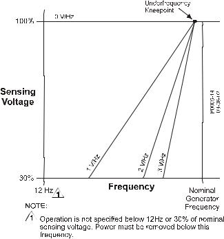
V/Hz Characteristic: |
Slope from 0 to 3PU is adjustable in 0.01PU increments. Transition |
|
(Corner) frequency is adjustable from 40 to 65 Hz. See Figure 1-2 for the |
|
|
V/Hz curves. |
|
|
Response Time: |
Within 1 cycle |
|
9287500991 Rev M |
DECS-100 General Information |
1-3 |
|
Figure 1-2. Typical V/Hz Curves |
||
FCR (Manual) Operating Mode |
||
|
Adjustment Range: |
0 to 7 Adc |
|
|
Increment: |
0.01 Adc |
|
Var Operating Mode (Optional) |
||
|
Adjustment Range: |
–100 to 100% |
|
|
Increment: |
0.1% |
|
PF Operating Mode (Optional) |
||
|
Adjustment Range: |
0.6 lag to 0.6 lead |
|
|
Increment: |
0.001 |
|
Parallel Compensation |
||
|
Modes: |
Reactive Droop and Reactive Differential (cross-current) |
|
|
Droop Adjust Range: |
0 to 10% |
|
|
Increment: |
1% |
|
|
Burden can exceed 1 VA if external resistors are added to the CT circuit. |
||
Field Overvoltage Protection |
||
|
Pickup Range: |
0 to 250 Vdc |
|
|
Time Delay: |
10 s (fixed) |
|
Generator Overvoltage Protection |
||
|
Pickup |
||
|
Range: |
100 to 120% of system voltage setting |
|
|
Increment: |
1.0% |
|
|
Alarm Time Delay |
||
|
Range: |
0 to 10 s |
|
|
Increment: |
1 s |
|
|
1-4 |
DECS-100 General Information |
9287500991 Rev M |
Overexcitation Limiter |
||
|
Pickup |
||
|
Range: |
0 to 15 Adc |
|
|
Increment: |
0.001 Adc |
|
|
Alarm Time Delay |
||
|
Range: |
0 to 10 s |
|
|
Increment: |
1 s |
|
Underexcitation Limiter |
||
|
Pickup |
||
|
Range: |
0 to 100% of rated vars |
|
|
Increment: |
1% |
|
|
Alarm Time Delay |
||
|
Range: |
0 to 10 s |
|
|
Increment: |
1 s |
|
Soft Start Function (AVR Mode Only) |
||
|
Time Adjust Range: |
1 to 7,200 s |
|
|
Increment: |
1 s |
|
Voltage Matching |
||
|
Accuracy: |
Generator rms voltage is matched with the bus rms voltage to within |
|
|
±0.5% of the generator voltage. |
||
|
Time Adjustment |
||
|
Range: |
1 to 300 s |
|
|
Increment: |
0.01 s |
|
Metering (BESTCOMS™) |
||
|
Generator Voltage |
||
|
Range: |
10 V to 79 kV |
|
|
Accuracy: |
±0.5% (at 25°C) |
|
|
Generator Current |
||
|
Range: |
0.04 to 3,000 Aac for 1 A CT (Not to exceed nominal CT rating) |
|
|
0.2 to 15,000 Aac for5 A CT (Not to exceed nominal CT rating) |
||
|
Accuracy: |
±0.5% (at 25°C) |
|
|
Frequency |
||
|
Range: |
40 to 65 Hz |
|
|
Accuracy: |
±0.2 Hz (at 25°C) |
|
|
Field Voltage |
||
|
Range: |
0 to 200 Vdc |
|
|
Accuracy: |
±5.0% (at 25°C) |
|
|
Field Current |
||
|
Range: |
0 to 20 A |
|
|
Accuracy: |
±0.5% (at 25°C) |
|
|
Bus Voltage |
||
|
Range: |
10 V to 79 kV |
|
|
Accuracy: |
±0.5% (at 25°C) |
|
|
Auxiliary DC Input |
||
|
Range: |
–3 V to +3 V |
|
|
Accuracy: |
±0.5% (at 25°C) |
|
|
9287500991 Rev M |
DECS-100 General Information |
1-5 |
Power (Apparent, Real, and Reactive)
|
Range: |
0 to 99 MVA, MW, Mvar |
|
Accuracy: |
±3.0% (at 25°C) |
|
Power Factor |
|
|
Range: |
–1.0 to –0.6, +0.6 to +1.0 |
|
Accuracy: |
±0.02 at rated current (25°C), CT input ≥10% nominal rating |
|
Phase Angle |
|
|
Range: |
0 to 360 degrees |
|
Accuracy: |
±2.0 degrees (at 25°C), CT input ≥10% nominal rating |
Environment |
|
|
Operating Temperature |
|
|
DECS-100: |
–40 to 70°C (–40 to 158°F) |
|
Storage Temperature |
|
|
DECS-100: |
–40 to 85°C (–40 to 185°F) |
|
CD-ROM: |
0 to 50°C (32 to 122°F) |
Type Tests |
|
|
Shock: |
Withstands 20 G in three perpendicular planes |
|
Vibration: |
Withstands 1.2 G at 5 to 26 Hz |
|
Withstands 0.914 mm (0.036 in) double amplitude at 27 to 52 Hz |
|
|
Withstands 5 G at 53 to 500 Hz |
|
|
Salt Fog: |
Qualified per MIL-STD-810E |
Physical |
|
|
Weight |
|
|
Unit: |
1.10 kg (2.42 lb) |
|
Shipping: |
1.31 kg (2.88 lb) |
|
Shipping Carton Dimensions (W x H x D) |
|
|
Single Unit: |
299 x 79 x 146 mm (11.75 x 3.125 x 5.75 in) |
|
48 Units: |
841 x 653 x 352 mm (33.13 x 25.69 x 13.88 in) |
Maritime Recognition
Recognized per standard IACS UR (sections E10 and E22) by the following:
•Bureau Veritas (BV) – BV Rules Pt. C, Ch. 3
•Det Norske Veritas (DNV) – No. 2.4
•Germanischer Lloyd (GL) – VI-7-2
IEC 60092-504 is the base standard for IACS UR section E10. IACS UR is the base standard for the BV, DNV, and GL rules listed above.
Additional conditions must be met in order to comply with maritime agency standards, see Section 4, Installation for further instructions.
EAC Mark (Eurasian Conformity)
•TP TC 004/2011
•TP TC 020/2011
UL Recognized Component
The DECS-100 is recognized to applicable Canadian and US safety standards and requirements by UL. Standards used for evaluation: UL6200
CE Compliance
LVD 2006/95/EC
BS EN 50178 – Electronic Equipment for use in Power Installations
EMC 2004/108/IEC
IEC 61000-6-2 – Electromagnetic Compatibility (EMC) Immunity for Industrial Environments
IEC 61000-6-4 – Electromagnetic Compatibility (EMC) Emissions Standard for Industrial Environments
|
1-6 |
DECS-100 General Information |
9287500991 Rev M |
SECTION 2 • HUMAN-MACHINE INTERFACE
TABLE OF CONTENTS
|
SECTION 2 • HUMAN-MACHINE INTERFACE …………………………………………………………………………… |
2-1 |
|
INTRODUCTION…………………………………………………………………………………………………………………… |
2-1 |
|
FRONT PANEL INDICATORS………………………………………………………………………………………………… |
2-1 |
|
Overexcitation Shutdown ……………………………………………………………………………………………………. |
2-1 |
|
Generator Overvoltage……………………………………………………………………………………………………….. |
2-1 |
|
Loss of Generator Sensing………………………………………………………………………………………………….. |
2-1 |
|
Overexcitation Limiting ……………………………………………………………………………………………………….. |
2-2 |
|
Underexcitation Limiting ……………………………………………………………………………………………………… |
2-2 |
|
Var/P.F. Mode Active …………………………………………………………………………………………………………. |
2-2 |
|
Manual Mode Active…………………………………………………………………………………………………………… |
2-2 |
|
Underfrequency Active ……………………………………………………………………………………………………….. |
2-2 |
|
COMMUNICATION PORT……………………………………………………………………………………………………… |
2-2 |
Figures |
|
|
Figure 2-1. DECS-100 Front Panel Indicators………………………………………………………………………………. |
2-1 |
|
Figure 2-2. DECS-100 Communication Port Location……………………………………………………………………. |
2-2 |
|
9287500991 Rev M |
DECS-100 Human-Machine Interface |
i |
This page intentionally left blank.
|
ii |
DECS-100 Human-Machine Interface |
9287500991 Rev M |
![]()
SECTION 2 • HUMAN-MACHINE INTERFACE
INTRODUCTION
The DECS-100 human-machine interface (HMI) consists of front panel indicators and a rear-panel communication port.
FRONT PANEL INDICATORS
DECS-100 front panel indicators consist of eight red LEDs. The indicators are shown in Figure 2-1 and described in the following paragraphs.
Figure 2-1. DECS-100 Front Panel Indicators
Overexcitation Shutdown
This LED lights when the Overexcitation Protection feature is enabled and the field voltage exceeds the adjustable setpoint for 10 seconds. The DECS-100 will shutdown when an overexcitation condition is detected. The Overexcitation Shutdown LED will light for 5 seconds when the DECS-100 is powered up following an overexcitation shutdown.
Generator Overvoltage
This LED lights when generator output voltage exceeds the adjustable setpoint for 0.75 seconds. When a generator overvoltage condition exists, the DECS-100 output contacts close and the DECS-100 shuts down (if hardware shutdown is enabled). The Generator Overvoltage LED will light for 5 seconds when the DECS-100 is powered up following a generator overvoltage shutdown.
Loss of Generator Sensing
This LED lights when a loss of generator sensing voltage is detected. When a loss of sensing condition occurs, the DECS-100 output contacts close. Depending on the protective action selected, the DECS-100 will either shutdown or transfer to Manual mode. The Loss of Generator Sensing LED will flash for 5 seconds when the DECS-100 is powered up following a loss of generator sensing shutdown.
|
9287500991 Rev M |
DECS-100 Human-Machine Interface |
2-1 |

Overexcitation Limiting
This LED lights when the field current exceeds the programmed overexcitation limit. It stays lit until the overexcitation condition ceases or the overexcitation time delay expires and the DECS-100 shuts down. The Overexcitation Limiting LED will flash for 5 seconds when the DECS-100 is powered up following an overexcitation limiting shutdown.
Underexcitation Limiting
This LED lights when the sensed, reactive power (leading vars) decreases below the programmed underexcitation limit. It stays lit until the underexcitation condition ceases or the underexcitation time delay expires and the DECS-100 shuts down. The Underexcitation Limiting LED will flash for 5 seconds when the DECS-100 is powered up following an underexcitation limiting shutdown.
Var/P.F. Mode Active
This LED lights to indicate that the DECS-100 is operating in the optional Var or Power Factor mode of control. Var/Power Factor control is enabled through BESTCOMS™ software and when the 52J/K contact input is open.
Manual Mode Active
This LED lights when the DECS-100 is operating in Manual mode. Manual mode is enabled through BESTCOMS software.
Underfrequency Active
This LED lights when the generator frequency decreases below the underfrequency setpoint and the DECS-100 is regulating on the selected volts per hertz curve.
COMMUNICATION PORT
The communication port is located on the rear panel and consists of a female, RS-232 (DB-9) connector. The communication port serves as an interface for programming (setup) of the DECS-100. Figure 2-2 illustrates the location of the communication port.
Programming requires a standard, nine-pin, serial communication cable connected between the DECS-100 and an IBM-compatible PC operating with BESTCOMS software. BESTCOMS software is a Microsoft Windows®-based communication software package that is supplied with the DECS-100. A detailed description of BESTCOMS is provided in Section 5, BESTCOMS Software.
WARNING!
Lethal voltage is present at the rear panel when the unit is energized. Rear panel connections should be made only when the unit is de-energized.
Figure 2-2. DECS-100
Communication Port Location
|
2-2 |
DECS-100 Human-Machine Interface |
9287500991 Rev M |
SECTION 3 • FUNCTIONAL DESCRIPTION
TABLE OF CONTENTS
|
SECTION 3 • FUNCTIONAL DESCRIPTION ………………………………………………………………………………. |
3-1 |
|
INTRODUCTION…………………………………………………………………………………………………………………… |
3-1 |
|
DECS-100 FUNCTION BLOCKS…………………………………………………………………………………………….. |
3-1 |
|
Analog Input Circuits ………………………………………………………………………………………………………….. |
3-1 |
|
Bus Voltage……………………………………………………………………………………………………………………. |
3-1 |
|
Generator Voltage ………………………………………………………………………………………………………….. |
3-1 |
|
B-Phase Line Current ……………………………………………………………………………………………………… |
3-2 |
|
Accessory Input (Auxiliary Adjust) …………………………………………………………………………………….. |
3-2 |
|
Field Voltage………………………………………………………………………………………………………………….. |
3-2 |
|
Field Current ………………………………………………………………………………………………………………….. |
3-2 |
|
Contact Input Circuits …………………………………………………………………………………………………………. |
3-2 |
|
Raise…………………………………………………………………………………………………………………………….. |
3-2 |
|
Lower ……………………………………………………………………………………………………………………………. |
3-2 |
|
Var/Power Factor Control (52J/K) Option…………………………………………………………………………… |
3-2 |
|
Parallel Generator Compensation (52L/M)…………………………………………………………………………. |
3-2 |
|
Voltage Matching Control Option………………………………………………………………………………………. |
3-3 |
|
RS-232 Communication Port……………………………………………………………………………………………….. |
3-3 |
|
Microprocessor………………………………………………………………………………………………………………….. |
3-3 |
|
Power Input Stage……………………………………………………………………………………………………………… |
3-3 |
|
Power Supply ……………………………………………………………………………………………………………………. |
3-3 |
|
Power Amplifier Stage………………………………………………………………………………………………………… |
3-3 |
|
Front Panel Indicators ………………………………………………………………………………………………………… |
3-3 |
|
Relay Output……………………………………………………………………………………………………………………… |
3-3 |
|
DECS-100 OPERATING FEATURES ……………………………………………………………………………………… |
3-3 |
|
Operating Modes……………………………………………………………………………………………………………….. |
3-3 |
|
Automatic Voltage Regulation Mode …………………………………………………………………………………. |
3-3 |
|
Manual Mode …………………………………………………………………………………………………………………. |
3-4 |
|
Var Control Mode (Optional)…………………………………………………………………………………………….. |
3-4 |
|
Power Factor Control Mode (Optional)………………………………………………………………………………. |
3-4 |
|
Reactive Droop Compensation ……………………………………………………………………………………………. |
3-4 |
|
Underfrequency…………………………………………………………………………………………………………………. |
3-4 |
|
Protection …………………………………………………………………………………………………………………………. |
3-4 |
|
Generator Overvoltage ……………………………………………………………………………………………………. |
3-5 |
|
Loss of Sensing Voltage ………………………………………………………………………………………………….. |
3-5 |
|
Field Overvoltage (Overexcitation Shutdown) …………………………………………………………………….. |
3-5 |
|
Limiters …………………………………………………………………………………………………………………………….. |
3-6 |
|
Overexcitation Limiting ……………………………………………………………………………………………………. |
3-6 |
|
Underexcitation Limiting ………………………………………………………………………………………………….. |
3-6 |
|
Soft Start…………………………………………………………………………………………………………………………… |
3-7 |
|
Voltage Matching (Optional)………………………………………………………………………………………………… |
3-7 |
Figures |
|
|
Figure 3-1. Simplified DECS-100 Block Diagram………………………………………………………………………….. |
3-1 |
|
Figure 3-2. Time Characteristic Curve for Takeover OEL………………………………………………………………. |
3-6 |
|
9287500991 Rev M |
DECS-100 Functional Description |
i |
This page intentionally left blank.
|
ii |
DECS-100 Functional Description |
9287500991 Rev M |
SECTION 3 • FUNCTIONAL DESCRIPTION
INTRODUCTION
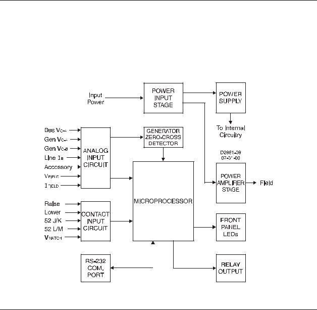
This section describes how the DECS-100 functions and explains its operating features. To ease understanding, DECS-100 functions are illustrated in the block diagram of Figure 3-1. A detailed description of each function block is provided in the paragraphs under the heading of DECS-100 Function Blocks.
DECS-100 operating features include four operating modes, four protective functions, startup provisions, reactive droop compensation, underfrequency compensation, and optional voltage matching. A detailed description of each operating feature is provided in the paragraphs under the heading of DECS-100 Operating Features.
Figure 3-1. Simplified DECS-100 Block Diagram
DECS-100 FUNCTION BLOCKS
The following paragraphs describe each of the function blocks illustrated in Figure 3-1. The function of each block is explained along with the operation of all function block inputs and outputs.
Analog Input Circuits
Seven analog voltages and current may be sensed and applied to the DECS-100.
Bus Voltage
C-phase and A-phase bus voltages are monitored at terminals B3 and B1 on units that include voltage matching. Nominal voltages of up to 600 Vac may be sensed at these terminals. Voltage monitored at this input is scaled and conditioned before being applied to the input of the analog-to-digital converter (ADC). This bus voltage signal applied to the ADC is used to calculate the rms value of the bus voltage across phases C and A (Bus VC-A).
Generator Voltage
Generator voltage is monitored at terminals E1 (A-phase), E2 (B-phase), and E3 (C-phase). Nominal voltages of up to 600 Vac may be sensed at these terminals. Voltage applied to these inputs is scaled
|
9287500991 Rev M |
DECS-100 Functional Description |
3-1 |
and conditioned before being applied to the input of the ADC. The voltage signal from phase C and A (VC-A) of the generator is used by the ADC to calculate the rms value of generator voltage across phases C and A. Likewise, the voltage signal from phase C and B (VC-B) of the generator is used by the ADC to calculate the rms value of generator voltage across phases C and B. The rms value of generator phase B to phase A voltage (VB-A) is calculated by the microprocessor from the phase C to phase A signal (VC-A)and the phase C to phase B (VC-B) signal.
Additionally, the generator phase C to phase A (VC-A) signal is applied to a filtered, zero-cross detector circuit. This signal is applied to the microprocessor and is used to calculate generator frequency.
B-Phase Line Current
The phase B line current (IB) signal is developed through a customer supplied current transformer (CT) and monitored through terminals CT1 and CT2. Depending on the option selected, current up to 1 ampere (style number xx1) or 5 amperes (style number xx5) rms may be monitored at these terminals. The current monitored at these terminals is scaled and conditioned by an internal current transformer and active circuitry for use by the ADC. The signal applied to the ADC is used to calculate the rms value of phase B line current.
Additionally, the phase angle between phase B line current and phase C to phase A generator voltage is calculated for use during droop and var/power factor operation.
Accessory Input (Auxiliary Adjust)
This input allows adjustment of the DECS-100 regulation setpoint by the application of a positive or negative dc voltage across terminals A and B. Positive voltage applied to terminal A with respect to terminal B will cause the active mode setpoint to increase. Voltage from –3 to +3 Vdc may be applied to this input. The circuit induces a 1,000-ohm burden on the dc source. The Application of a ±3 Vdc signal corresponds to a ±30 percent change in setpoint.
Field Voltage
Voltage (VFIELD) across the regulator field output terminals, F+ and F–, is monitored, scaled, and conditioned before being applied to the ADC. This signal is used to calculate the dc value of field voltage for use in system protection.
Field Current
Current (IFIELD) through the main power output switch is converted to a proportional voltage level. This voltage signal is scaled and conditioned before being applied to the input of the ADC. The result is used to calculate the dc value of field current for use in the Manual mode of operation as well as protection of the system.
Contact Input Circuits
Five contact input circuits powered from an internal 13 Vdc power supply provide input control from usersupplied, isolated, dry-type contacts.
Raise
Closing a contact across terminals 6U and 7 causes the active operating setpoint to increase. This function is active as long as the contact is closed.
Lower
Closing a contact across terminals 6D and 7 causes the active operating setpoint to decrease. This function is active as long as the contact is closed.
Var/Power Factor Control (52J/K) Option
Closing a contact across terminals 52J and 52K disables var/power factor control. An open contact enables the DECS-100 to control the generator reactive power in either the var or the power factor mode. The contact has no effect when this function is not enabled in the software. For more information, see
Parallel Generator Compensation (52L/M) and Voltage Matching Control Option. Parallel Generator Compensation (52L/M)
Closing a contact across terminals 52L and 52M disables parallel operation. An open contact enables parallel operation and the DECS-100 operates in reactive droop compensation mode.
|
3-2 |
DECS-100 Functional Description |
9287500991 Rev M |
 Loading…
(Ocr-Read Summary of Contents of some pages of the Basler DECS-100 Document (Main Content), UPD: 21 August 2023)
-
41, DECS-100 BESTCOMS for Windows ® OS 5-5 Figure 5-9. Setting Adjustments Screen, Setpoint Tab Setting Adjustments The Setting Adjustments screen consists of two tabs: Setpoint and Startup. Setpoint Tab The Setpoint tab settings of the Setting Adjustments screen are shown in Figure 5-9. Each setting of the Setpoint tab is described in the following paragraphs. Automatic Voltage Regulator (AVR) — …
-
31, DECS-100 Installation 4-9 Figure 4-7. Typical Connections for PMG Application with ABC Rotation and Single-Phase Sensing
… -
50, DECS-100 BESTCOMS for Windows ® OS5-14 Figure 5-17. Metering, Operation, and Alarms, Operation Tab Loss of Sensing Voltage — Hardware Shutdown. Enabling Hardware Shutdown will cause the DECS-100 to remove field excitation when a loss of sensing voltage occurs. Disabling Hardware Shutdown prevents the DECS-100 from removing excitation during a loss of sensing voltage. Generator Overvoltage — Voltage Level (%). The value of this field is expressed as a perce…
-
72, DECS-100 Maintenance and Troubleshooting 7-1 SECTION 7 • MAINTENANCE AND TROUBLE- SHOOTING PREVENTIVE MAINTENANCE The only preventive maintenance required on the DECS-100 is to periodically check that the connections between the DECS-100 and the system are clean and tight. DECS-100 units are manufactured using state- of-the-art, surface-mount technology. As such, Basler Electric recommends that no repair procedures be attempted by anyone other than Basler …
-
68, DECS-100 BESTCOMS for Palm OS ® 6-7 Regulation and Voltage Matching Buttons Tapping the Reg. Mode button toggles between Field Current Regulation (FCR) mode and Automatic Voltage Regulation (AVR) mode. Tapping the VM Mode button toggles the voltage matching function between the On and Off state. The example of Figure 6-16 shows a DECS-100 operating in the AVR mode with voltage matching disabled. Note that voltag…
-
29, DECS-100 Installation 4-7 Figure 4-5. Personal Computer to DECS-100 Connections DECS-100 Connections for Typical Applications Figures 4-6 through 4-9 illustrate typical applications using the DECS-100. Figure 4-6 shows an application where DECS-100 operating power is derived from a permanent magnet generator (PMG) and three-phase voltage sensing is applied to the DECS-100. Figure 4-7 shows another PMG application but with sing…
-
19, DECS-100 Functional Description3-4 DECS-100 OPERATING FEATURES The following paragraphs describe the characteristics of each DECS-100 operating feature. Operating Modes The DECS-100 provides up to four modes of operation selectable through BESTCOMS software. Automatic voltage regulation mode and Manual mode are standard features. Var and Power Factor modes are an option. Automatic Voltage Regulation Mode In Automatic Voltage Regulation (AVR) mode, the DECS-100 regulates rms ge…
-
71, DECS-100 Maintenance and Troubleshooting i SECTION 7 • MAINTENANCE AND TROUBLE- SHOOTING TABLE OF CONTENTS SECTION 7 • MAINTENANCE AND TROUBLE-SHOOTING ………………………… 7-1 PREVENTIVE MAINTENANCE ……………………………………… 7-1 TROUBLESHOOTING ……………………………………………. 7-1 Generator Voltage Does Not Build …………………………………. 7-1 …
-
56, DECS-100 BESTCOMS for Windows ® OS5-20 Figure 5-21. Settings Upload Dialog Box Figure 5-22. Password Dialog Box The upload process is started by clicking the open icon or clicking F ile on the menu bar and then clicking O pen . A dialog box is then displayed (Figure 5-21) reminding you that the DECS-100 should be off-line before uploading settings. Clicking Y es loads the settings into DECS-100 memory. PASSWORD PROTECTION Passwor…
-
28, DECS-100 Installation4-6 Power Supply Inputs Power input terminals are labeled 3, 4, and 5. Single-phase or three-phase power may be applied. Single- phase power may be applied to any two of the three terminals. Chassis Ground The chassis ground terminal is labeled GND. Power (Field) Output The field output terminals for connection to the generator exciter field are labeled F+ and F–. Relay Output The common alarm relay output contact may be accessed at the term…
-
35, DECS-100 BESTCOMS for Windows ® OS i SECTION 5 • BESTCOMS SOFTWARE FOR THE WINDOWS ® OPERATING SYSTEM TABLE OF CONTENTS SECTION 5 • BESTCOMS SOFTWARE FOR THE WINDOWS ® OPERATING SYSTEM …….. 5-1 INTRODUCTION ……………………………………………………… 5-1 INSTALLATION ………………………………………………………. 5-1 Installing BESTCOMS-DECS100-32 ……………………………………… 5-1 C…
-
27, DECS-100 Installation 4-5 Bus Voltage Sensing Inputs (Optional) The bus voltage sensing terminals are labeled B1 and B3. These terminals are used only on units that include the Voltage Matching option. Table 4-1 lists the terminal assignments for bus voltage sensing. Table 4-1. Bus Voltage Sensing Terminals Bus Voltage Phase Terminal AB1 CB3 Generator Voltage Sensing Inputs The generator voltage sensing terminals ar…
-
30, DECS-100 Installation4-8 Figure 4-6. Typical Connections for PMG application with ABC Rotation and Three-Phase Sensing
… -
17, DECS-100 Functional Description3-2 Generator Voltage Generator voltage is monitored at terminals E1 (A-phase), E2 (B-phase), and E3 (C-phase). Nominal voltages of up to 600 Vac may be sensed at these terminals. Voltage applied to these inputs is scaled and conditioned before being applied to the input of the ADC. The voltage signal from phase C and A (V C-A ) of the generator is used by the ADC to calculate the RMS value of generator voltage across phases C and A. Likewise, the voltage …
-
20, Basler DECS-100 DECS-100 Functional Description 3-5 Underfrequency When generator frequency drops below the selected knee frequency setpoint, the voltage setpoint is automatically adjusted by the DECS-100 so that generator voltage follows the selected PU (per unit) V/Hz curve. When operating on the selected PU V/Hz curve, the UNDERFREQUENCY ACTIVE indicator lights on the front panel and in BESTCOMS. Underfrequency control is disabled belo…
-
61, Basler DECS-100 DECS-100 BESTCOMS for Palm OS ® i SECTION 6 • BESTCOMS SOFTWARE FOR THE PALM OS ® PLATFORM TABLE OF CONTENTS SECTION 6 • BESTCOMS SOFTWARE FOR THE PALM OS ® PLATFORM ……………….. 6-1 INTRODUCTION ……………………………………………………… 6-1 INSTALLATION ………………………………………………………. 6-1 Installing BESTCOMS ………………………………….…
-
38, Basler DECS-100 DECS-100 BESTCOMS for Windows ® OS5-2 Figure 5-2. BESTCOMS Title and Version Figure 5-3. System Configuration Screen Figure 5-4. Communication Port Menu Selection Figure 5-5. Password Dialog Box Figure 5-6. Communication Initialization Screen Establishing Communication Communication between BESTCOMS and the DECS-100 must be established before viewing metering values or reading or changing settings. BESTCOMS screen settings are updat…
-
10, DECS-100 General Information 1-3 Figure 1-2. Typical V/Hz Curves Contact Input Circuits–continued Terminal Assignments for Optional Functions Var/PF Enable: 52J, 52K Voltage Matching: VM, VMC Common Alarm Output Type: Form A Rated Load: 7 Aac/Adc continuous Make: 30 Aac/Adc, carry for 0.2 sec Break: 7 Aac/0.1 Adc Operating Voltage: 240 Vac/250 Vdc maximum Terminals: AL1, AL2 Field Output Field Resistance: 5 S minimum Terminals: F+, F– Continuous Rating: 63 Vdc, 7 Adc 10 Second Forcing Ratin…
-
15, Basler DECS-100 DECS-100 Functional Description i SECTION 3 • FUNCTIONAL DESCRIPTION TABLE OF CONTENTS SECTION 3 • FUNCTIONAL DESCRIPTION ……………………………………… 3-1 INTRODUCTION ……………………………………………………… 3-1 DECS-100 FUNCTION BLOCKS …………………………………………… 3-1 Analog Input Circuits ………………………………………………… 3-1 Bus Voltage ……………………………..…
 07:00
07:00
Tutorial — basler decs 250 over limit excitation
 03:04
03:04
Wiring and testing avr basler decs 250 di genset perkins 350kva
 04:34
04:34
Snapshot Interactive | Basler Electric «75th Anniversary»
 05:05
05:05
Basler Electric Wasselonne en grève
 02:58
02:58
Decs 250 -cara komunikasi AVRZ BASLER ke laptop mengunakan kabel usb
 18:44
18:44
Motorcoach Electrical repairs — 15KVADiesel Genset exciter and contactor repair
 04:51
04:51
Shayna Baszler vs. Rhea Ripley – NXT Women’s Championship Match: WWE NXT, Dec. 18, 2019
РУКОВОДСТВО ПО ЭКСПЛУАТАЦИИ ЦИФРОВОЙ СИСТЕМЫ УПРАВЛЕНИЯ ВОЗБ…
Руководство по эксплуатации, Цифровой системы управления возбуждением decs-100
- Изображение
- Текст
- Содержание
РУКОВОДСТВО
ПО ЭКСПЛУАТАЦИИ
ЦИФРОВОЙ СИСТЕМЫ
УПРАВЛЕНИЯ ВОЗБУЖДЕНИЕМ
DECS-100
Публикация: 9287573991
Редакция: M 02.2015

ВВЕДЕНИЕ
В настоящем руководстве по эксплуатации приведена информация по установке и эксплуатации
цифровой системы управления возбуждением DECS-100. Для выполнения поставленной задачи
в руководство включены следующие сведения
•
Общая информация и технические характеристики
•
Органы управления и индикаторы
•
Функциональное описание
•
Установка
•
Техническое обслуживание. Поиск и устранение неисправностей
ПРЕДУПРЕЖДЕНИЕ!
Во избежание травм персонала или повреждения оборудования все
процедуры, приведенные в настоящем руководстве, должны выполняться
квалифицированными специалистами.
Если на устройство подано напряжение, его задняя панель находится под
смертельно опасным напряжением. Подключения к разъемам, размещенным
на задней панели, должны выполняться только при обесточенных цепях
устройства.
ПРИМЕЧАНИЕ
Убедитесь, что система DECS-100 подключена к точке заземления при
помощи медного провода диаметром не менее 12 AWG, соединенного
с заземляющим выводом на тыльной стороне корпуса устройства. При
выполнении настройки конфигурации DECS-100 в системе, куда включены
и другие устройства, рекомендуется предусмотреть для каждого устройства
отдельный заземляющий провод и подключить его к шине заземления.
ВНИМАНИЕ!
Уровень возбуждения в ручном режиме необходимо оценить до того, как
будет задействована данная функция. Если уровень тока возбуждения не
соответствует требованиям со стороны генератора, это может нанести ему
серьезные повреждения.
Использование ненадлежащих ПИД-коэффициентов приведет к низким
эксплуатационным характеристикам системы и может вывести ее из строя.
При подаче рабочего напряжения с целью выполнения программирования
соблюдайте меры предосторожности, приведенные в разделе 4 «Установка
и предварительная наладка».
При программировании системы DECS-100 без вращения генератора
проводники, подключенные к клеммам F+ и F– системы DECS-100, должны
быть отсоединены.
Прежде чем загружать файл с настройками обесточьте систему DECS-100,
отключите кабели возбуждения от соединительных клемм F+ и F–, после
чего снова подайте рабочее напряжение на DECS-100.
9287573991 ред. M
DECS-
100. Введение
i

Первая публикация: март 2001 г.
Отпечатано в США
© Basler Electric, 2015. Highland Illinois 62249 USA (
США)
Все права защищены
Настоящее руководство не имеет своей целью представить детальное описание и все варианты
поставки оборудования, а также не содержит данных обо всех чрезвычайных ситуациях, которые
могут возникнуть в процессе установки или эксплуатации системы. Доступность функций и их
особенности, а также комплектация системы могут быть изменены без предварительного
уведомления. Для получения дополнительной информации необходимо связаться с представителем
компании Basler Electric.
Условия обслуживания настоящего продукта и программного обеспечения приведены в документе
«Коммерческие условия предоставления продуктов и услуг», который доступен на веб-
странице
www.basler.com/terms
.
BASLER ELECTRIC
12570 State Route 143
Highland IL 62249-1074 USA (
США)
http://www.basler.com, info@basler.com
Тел.: +1 618 654 2341
Факс: +1 618 654 2351
КОНФИДЕНЦИАЛЬНАЯ
ИНФОРМАЦИЯ
© Basler Electric, Highland Illinois, USA (США). Настоящий документ передан
во временное пользование при условии его использования с соблюдением
мер защиты конфиденциальности. Он подлежит возврату по требованию.
Также подразумевается, что данная информация не может использоваться
в любых целях, наносящих вред компании Basler Electric.
ii
DECS-
100. Введение
9287573991 ред. M

СОДЕРЖАНИЕ Подробное содержание приводится в начале каждого…
Страница 5
- Изображение
- Текст

Данная страница умышленно оставлена пустой. viii DECS…
Страница 6
- Изображение
- Текст
Данная страница умышленно оставлена пустой.
viii
DECS-
100. Введение
9287573991 ред. M

ИСТОРИЯ РЕДАКЦИЙ
Данная информация представляет собой хронологическую сводку об изменениях, внесенных
в аппаратное обеспечение, микропрограммы и программное обеспечение системы DECS-100.
Соответствующие редакции настоящего руководства пользователя (9287573991) также приняты во
внимание. Редакции приводятся в хронологическом порядке.
Оборудование
Версия и дата выпуска
Изменение
E, 01.01
•
Первая публикация
F, 05.01
•
Углублена оболочка для заливки компаундом
G, 10.01
•
Начата поставка монтажных винтов
H, 02.02
•
Между силовыми компонентами и радиаторами уложены
электроизолирующие теплопроводные прокладки SIL-PADS
•
В паспортную табличку на тыльной стороне устройства добавлена
страна-изготовитель изделия
J, 07.02
•
Пересмотрена модель электронно-программируемого ПЗУ (EEPROM)
K, 02.03
•
Заменен транзистор Q8B1 на усовершенствованную деталь
L, 03.03
•
Выполнен очередной этап усовершенствования микропрограммы
и BESTCOMS™
M, 01.04
•
Улучшены возможности хранения данных в флеш-памяти
N, 05.05
•
Перепроектирован трансформатор тока
•
На переднюю панель добавлен индикатор ограничения недовозбуждения
•
Повышена стойкость к электромагнитным/радиопомехам
O
•
Буква O не использовалась для обозначения версии
P, 08.06
•
Обновлен компакт-диск, поставляемый в комплекте с устройством,
на котором содержится руководство по эксплуатации на английском
и французском языках
Q
•
Буква Q не использовалась для обозначения версии
R, 04.07
•
Разрешена проблема с недовозбуждением (UEL) за счет внесения
изменений в микропрограмму
S, 05/07
•
Компакт-диск, поставляемый в комплекте с DECS-100, дополнен
инструкцией по эксплуатации на немецком языке
T, 07.07
•
Выпущена микропрограмма версии 2.13.XX
U, 01.08
•
Внесены усовершенствования в силовые цепи усилителя за счет
установки более надежных компонентов
V, 03.08
•
Добавлена функция автоматического сохранения уставок
W, 03.09
•
Выпущено программное обеспечение BESTCOMS версии 1.08.XX.
X, 02.10
•
Внесены усовершенствования в процесс заводских испытаний.
Микропрограмма
Версия и дата выпуска
Изменение
1.09.XX, 01.01
•
Первая публикация
1.11.XX, 07.01
•
Включена возможность использования функции защиты в течение
первых 5 секунд функционирования
•
Изменен коэффициент масштабирования уставки OEL (ограничения
перевозбуждения) с целью обеспечения совместимости с BESTCOMS
версии 1.03.XX
•
Добавлен коэффициент масштабирования коэффициента усиления
в относительных единицах
•
Минимальное значение регулировки напряжения установлено на 30%
номинального значения считываемого напряжения
1.12.XX, 03.02
•
Добавлен регистр для определения типа ТТ
2.13.XX, 07.07
•
Добавлено ограничение недовозбуждения
•
Добавлено ограничение возбуждения с возможностью перехода
в ручной режим регулировки
•
Добавлены средства согласования напряжений шины
2.14.XX, 03.08
•
Добавлен параметр, задающий автоматическое сохранение уставок
2.14.XX, 04.14
•
Отладочная версия
9287573991 ред. M
DECS-
100. Введение
iii

BESTCOMS для
ОС Windows
®
Версия и дата выпуска
Изменение
1.02.XX, 02.01
•
Первая публикация
1.03.XX, 08.01
•
Изменен масштаб ограничения перевозбуждения (OEL) со 100 на
1000 для обеспечения соответствия с измененной микропрограммой
версии 1.11.01
•
Изменено значение по умолчанию для уставки ограничения
перевозбуждения (OEL) с 1 на 15
•
Изменены значения по умолчанию для всех функций защиты на
«Активна»
•
Добавлена поддержка региональных параметров настройки для Франции
1.04.XX, 04.02
•
Программное обеспечение BESTCOMS стало совместимым с более
старыми версиями микропрограммы
•
Добавлена поддержка региональных параметров настройки
•
Активирована функция считывания значения на вторичной обмотке ТТ
для устройств с версией микропрограммы 1.12.01 и более поздней
•
Упрощено представление экрана «Анализ»
•
Добавлена функция расчета и отправки согласования опорного
напряжения для различных коэффициентов трансформации силовых
трансформаторов генераторов и шин
•
Изменено минимальное значение уставки Ki с 0 на 0,01
1.05.XX, 05.05
•
Добавлена возможность использовать ограничение недовозбуждения
•
Добавлена возможность выбора между использованием для
ограничения перевозбуждения (OEL) либо точки суммирования,
либо перехода в ручной режим
•
Добавлены средства согласования напряжений шины
1.06.XX, 11.07
•
В программное обеспечение BESTCOMS добавлена совместимость
с ОС Microsoft® Vista
1.07.XX, 03.08
•
Добавлен параметр, задающий автоматическое сохранение уставок.
1.08.XX, 03.09
•
Усовершенствован обмен данными с DECS-100.
1.09.XX, 01.11
•
Добавлена совместимость с Windows
®
7 и усовершенствована
функция останова по перенапряжению цепи возбуждения.
1.09.XX, 04.14
•
Добавлена совместимость с Windows
®
8
Программное
обеспечение
BESTCOMS
для Palm
®
OS
Версия и дата выпуска
Изменение
1.01.XX, 01.01
•
Первая публикация
1.08.XX, 02.01
•
Добавлена кнопка «Проверить наличие новой версии» на экран
«Связаться с Basler»
•
Добавлена отметка даты/времени в имена файлов для функции
«Сохранить в файл»
•
Добавлена проверка версии
1.03.XX, 04.02
•
Добавлена парольная защита
•
Усовершенствована функция проверки версии
ПРИМЕЧАНИЕ
•
Программное обеспечение BESTCOMS для Palm OS совместимо
с микропрограммами версии 1.12.XX и более поздними
Редакция и дата
выпуска руководства
Изменение
—, 03.01
•
Первая публикация
A, 03.01
•
В разделе 5 «Программное обеспечение BESTCOMS для ОС
Windows®»
и в разделе 6 «Программное обеспечение BESTCOMS
для платформы Palm OS®» шаг 2 процедуры «Установка
программного обеспечения BESTCOMS» был пересмотрен с целью
отражения в нем добавления утилиты автоматического запуска
iv
DECS-
100. Введение
9287573991 ред. M

Редакция и дата выпуска руководства Изменение компакт…
Страница 9
- Изображение
- Текст
Редакция и дата
выпуска руководства
Изменение
компакт-диска DECS-100
B, 08.01
•
В раздел 5 «Программное обеспечение BESTCOMS для ОС
Windows®»
добавлен подраздел «Встроенное программное
обеспечение»
•
Откорректированы различные незначительные ошибки в руководстве
C, 05.02
•
Пересмотрены требования по моментам затяжки монтажных винтов,
поставляемых в комплекте с устройством
•
В разделе 5 «Программное обеспечение BESTCOMS для ОС
Windows®»
и в разделе 6 «Программное обеспечение BESTCOMS
для платформы Palm® OS» были пересмотрены тексты и
иллюстрации с целью их адаптации к усовершенствованиям,
внесенным в программное обеспечение
D, 01.03
•
Пересмотрен диапазон регулировки времени согласования
напряжений и изменен во всем руководстве с «от 0 до 300 секунд» на
«от 1 до 300 секунд»
•
В разделах 5 и 6 откорректированы номера позиций на рисунках
E, 03.04
•
В раздел 4 «Установка и предварительная наладка» добавлен
подраздел «Рекомендации в отношении подачи рабочего
напряжения в процессе программирования DECS-100»
•
Добавлены предостережения относительно подачи рабочего напряжения
в процессе программирования DECS-100 — в раздел 5 «Программное
обеспечение BESTCOMS для ОС Windows®» и в раздел 6
«Программное обеспечение BESTCOMS для платформы Palm® OS»
•
Откорректирован диапазон значений коэффициента трансформации
ТТ, приведенный в разделе 5
F, 05.05
•
Добавлен материал с описанием новой возможности по ограничению UEL
•
Пересмотрены все чертежи с целью отображения на новой передней
панели индикатора UEL
•
Обновлены все иллюстрации с изображением задней панели с учетом
изменений в ТТ
•
Добавлены обсуждения вариантов с использованием точки
суммирования и перехода в ручной режим для ограничения OEL
•
Пересмотрено описание согласования напряжений с учетом режимов
удержания и возврата
•
Откорректирован диаметр просверленного отверстия, показанного на
рис. 4-2
•
Добавлены иллюстрация и описание по использованию ICRM-7
с системой DECS-100
•
Удален раздел 6 «Программное обеспечение BESTCOMS для
платформы Palm® OS» и добавлен раздел 6 «Техническое
обслуживание. Поиск и устранение неисправностей»
•
Добавлена процедура поиска и устранения неисправностей при
отображении сообщения UEL
G, 03.07
•
Откорректированы иллюстрация и описание экрана «Измерения,
функционирование и аварийные сигналы», а также вкладки
«Функционирование» программного обеспечения BESTCOMS
•
Удалена информация о патентах, срок действия которых истек
H, 05.08
•
В данные по руководству добавлено заявление об обеспечении
соответствия требованиям DNV
•
Добавлено описание функции BESTCOMS, обеспечивающей
автоматическое сохранение уставок
J, 10.08
•
Пересмотрены диапазоны регулировки для настроек коэффициента
усиления контуров управления OEL KI, OEL Kg, UEL KI и UEL Kg
с 0–1000 на 0–300 для отражения изменений в программном
обеспечении BESTCOMS с версии 1.07.01.
K, 05.11
•
Пересмотрен раздел «Введение» с целью отражения в нем
информации о новом блоке, залитом эпоксидным компаундом.
9287573991 ред. M
DECS-
100. Введение
v

Редакция и дата
выпуска руководства
Изменение
•
Из примечания 5 к рис. 4-7 — 4-10 изъята фраза «(функция является
опцией)», поскольку функция, использующая уставку, теперь входит
в стандартную конфигурацию.
•
В раздел 6 добавлена процедура для
накопительных/электролитических конденсаторов.
•
Откорректированы различные незначительные ошибки в руководстве
L, 07.13
•
Раздел 1: добавлена аккредитация морского агентства.
•
Раздел 1: в таблицы основных характеристик добавлены данные по
рассеиваемой мощности.
•
Раздел 4: добавлены условия приемлемости со стороны морского
агентства.
•
Раздел 4: добавлен блок, относящийся к рабочему напряжению 24 В
пост. тока, применяемому для программирования DECS-100.
•
Раздел 5: добавлен блок, относящийся к расчету ПИД-регулирования,
а также инструкция, допускающая 5-секундную задержку после
отправки параметров или микропрограммы на DECS-100.
•
Раздел 5: добавлено описание Дифференциальный коэффициент
усиления TD.
•
Раздел 6: добавлена процедура обеспечения подачи питания для
сохранения рабочего состояния электролитических конденсаторов
в режиме накопления.
M, 02.15
•
Добавлена аккредитация UL на соответствие UL6200.
•
Добавлена сертификация EAC.
•
Добавлены рекомендации относительно ферритового зажима для
обеспечения совместимости установки с требованиями по маркировке CE.
•
Незначительные исправления текста.
vi
DECS-
100. Введение
9287573991 ред. M

Комментарии
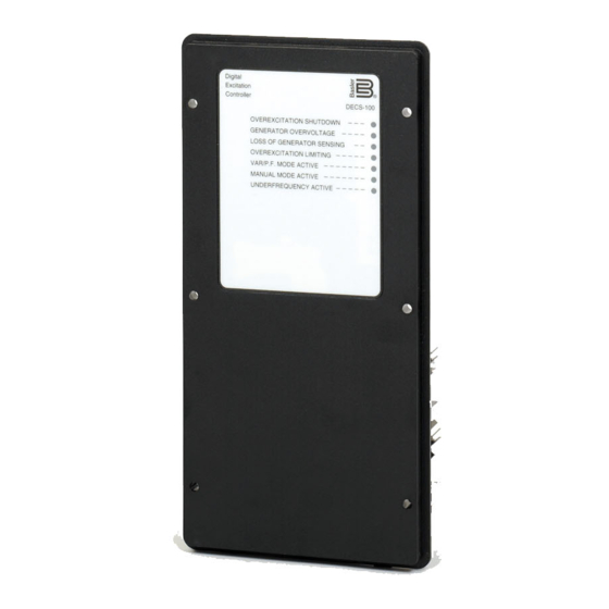
-
Contents
-
Table of Contents
-
Troubleshooting
-
Bookmarks
Quick Links
Chapters
-
Section 1 • General Information
7 -
Section 2 • Human-Machine Interface
12 -
Section 4 • Installation
22 -
Section 5 • Bestcoms Software for the Windows Operating System
35 -
Section 6 • Bestcoms Software for the Palm OS Platform
61 -
Section 7 • Maintenance and Trouble- Shooting
71
Related Manuals for Basler DECS-100
Summary of Contents for Basler DECS-100
-
Page 2
DECS-100. NOTE Be sure that the DECS-100 is hard-wired to earth ground with no smaller than 12 AWG copper wire attached to the ground terminal on the rear of the unit case. When the unit is configured in a system with other devices, it is recommended to use a separate lead to the ground bus from each unit. -
Page 3
August 2001 CONFIDENTIAL INFORMATION of Basler Electric, Highland, IL. It is loaned for confidential use, subject to return on request, and with the mutual understanding that it will not be used in any manner detrimental to the interest of Basler Electric. -
Page 4
MANUAL REVISION HISTORY The following information provides a historical summary of the changes made to the DECS-100 Instruction Manual (9 2875 00 991). Revisions are listed in reverse chronological order. Manual Version, ECO, and Date Change Rev B, 14282, 08/01 Added Embedded Software subsection to Section 5, BESTCOMS Software for the Windows Operating System . -
Page 5
DECS-100 Introduction… -
Page 6
Section 7 Maintenance and Troubleshooting ……. . . 7-1 DECS-100 Introduction… -
Page 7: Table Of Contents
Figure 1-1. DECS-100 Style Chart ……..
-
Page 8: Section 1 • General Information
Upon receipt of a DECS-100, be sure to check the style number against the requisition and the packing list to ensure that they agree.
-
Page 9: Specifications
A ..No var or power factor control 1 ..Voltage matching 5 ..5 ampere CT secondary SPECIFICATIONS DECS-100 electrical and physical specifications are listed in the following paragraphs. Operating Power Bus Voltage Sensing (Optional)–continued Three-Phase:…
-
Page 10: Common Alarm Output
Generator Voltage Range: 10 V to 79 kV Accuracy: ±0.5% (at 25EC) Generator Current Range: 0.04 to 1,000 A (1 A CTs) 0.1 to 5,000 A (5 A CTs) Accuracy: ±0.5% (at 25EC) Figure 1-2. Typical V/Hz Curves DECS-100 General Information…
-
Page 11: Environment
299 mm x 79 mm x 146 mm (11.75″ x 3.125″ x 5.75″) 48 Units: 841 mm x 653 mm x 352 mm (33.13″ x 25.69″ x 13.88″) UL Recognition Recognized per Standard 508, UL File E97035 DECS-100 General Information…
-
Page 12
Table 2-1. DECS-100 Front Panel Indicator Descriptions …….. -
Page 13: Section 2 • Human-Machine Interface
FRONT PANEL INDICATORS DECS-100 front panel indicators consist of seven red LEDs. Figure 2-1 shows the front panel indicators for the DECS-100. Table 2-1 describes the function of each front panel indicator. Figure 2-1. DECS-100 Front Panel Indicators Table 2-1.
-
Page 14: Communication Port
DECS-100 is powered up following an overexcitation limiting shutdown. Var/P.F. Mode Active This LED lights to indicate that the DECS-100 is operating in the optional Var or Power Factor mode of control. Var/Power Factor control is enabled through BESTCOMS software and when the 52J/K contact input is open.
-
Page 15
DECS-100 OPERATING FEATURES …….. -
Page 16
DECS-100 functions are illustrated in the block diagram of Figure 3-1. A detailed description of each function block is provided in the paragraphs under the heading of DECS-100 Function Blocks . DECS-100 operating features include four operating modes, four protective functions, startup provisions, reactive droop compensation, underfrequency compensation, and optional voltage matching. -
Page 17
Accessory Input (Auxiliary Adjust) This input allows adjustment of the DECS-100 regulation setpoint by the application of a positive or negative dc voltage across terminals A and B. Voltage of up to +3 Vdc may be applied to this input. The circuit induces a 1,000-ohm burden on the dc source. -
Page 18
Closing a contact across terminals 52J and 52K disables var/power factor control. An open contact enables the DECS-100 to control the generator reactive power in either the var or the power factor mode. The contact has no effect when this function is not enabled in the software. For more information, refer to the Parallel Generator Compensation (52L/M) contact input. -
Page 19
Accessory input, or through BESTCOMS software. Reactive Droop Compensation The DECS-100 provides a reactive droop compensation feature to assist in the sharing of reactive load during parallel generator operation. When this feature is enabled, the DECS-100 calculates the reactive portion of the generator load using the sensed generator output voltage and current quantities and then modifies the voltage regulation setpoint accordingly. -
Page 20
LOSS OF GENERATOR SENSING indicator will light for 5 seconds. If transfer to manual is selected and a loss of sensing occurs, the relay output closes, and the DECS-100 transfers to the Manual mode of operation after the adjustable time delay expires. The DECS-100 will remain in this mode of operation until power is cycled. -
Page 21
Overexcitation Limiting (Field Current) The DECS-100 field current limit is adjustable from 0 to 15 amperes in 0.1 ampere increments with an adjustable time delay that has a range of 0 to 10 seconds in 1 second increments. Both settings are made through BESTCOMS software. -
Page 22
DECS-100 Connections for Typical Applications …….. -
Page 23: Section 4 • Installation
MOUNTING The DECS-100 is normally located in the generator conduit box. It is designed for behind the panel mounting and requires a cutout for front panel viewing. Mounting hardware consists of six customer supplied, #12 thread-forming screws that pass through mounting holes in the conduit box and thread into the plastic shell of the DECS-100.
-
Page 24
Figure 4-1. DECS-100 Dimensions DECS-100 Installation… -
Page 25
Figure 4-2. Cutout and Drilling Dimensions DECS-100 Installation… -
Page 26: Connections
IBM compatible PCs and hand-held computers. Figure 4-3 shows the terminal connections located on the rear panel of the DECS-100. Except as noted above, connections should be made with minimum wire size of 14 AWG.
-
Page 27: Bus Voltage Sensing Inputs (Optional)
6U, 7, and 6D. To connect this switch, the center pole, or common terminal, must be connected to terminal 7. The other two terminals are connected to terminals 6U and 6D. This remote adjust switch may be mounted up to 150 feet away from the DECS-100 when using twisted, shielded cable.
-
Page 28: Power Supply Inputs
The RS-232 port on the rear panel uses a DB-9 female connector. Figure 4-4 Illustrates the pin assignments of the communication port and Table 4-3 Identifies the RS-232 connector pin functions. A standard communication cable terminated with a DB-9 male connector is used for PC interface with the DECS-100 as shown in Figure 4-5.
-
Page 29: Decs-100 Connections For Typical Applications
DECS-100 operating power is derived from a permanent magnet generator (PMG) and three-phase voltage sensing is applied to the DECS-100. Figure 4-7 shows another PMG application but with single-phase voltage sensing. Figure 4-8 shows an application where DECS-100 operating power is derived from the generator output (shunt application) and three-phase voltage sensing is applied to the DECS-100.
-
Page 30
Figure 4-6. Typical Connections for PMG application with ABC Rotation and Three-Phase Sensing DECS-100 Installation… -
Page 31
Figure 4-7. Typical Connections for PMG Application with ABC Rotation and Single-Phase Sensing DECS-100 Installation… -
Page 32
Figure 4-8. Typical Connections for Shunt Application with ABC Rotation and Three-Phase Sensing 4-10 DECS-100 Installation… -
Page 33
Figure 4-9. Typical Connections for Shunt Application with ABC Rotation and Single-Phase Sensing DECS-100 Installation 4-11… -
Page 34: Preliminary Setup
Before starting the generator and DECS-100 for the first time, proceed as follows. 1. Tag and disconnect all wiring to the DECS-100. Be sure to insulate the wire terminals to prevent a short circuit.
-
Page 35
Saving Settings to DECS-100 Memory …….. -
Page 36
Figure 5-25. DECS-100 Embedded Program Loader …….. -
Page 37: Operating System
Connect a communication cable between the rear RS-232 connector of the DECS-100 and the appropriate communication port of the PC. Refer to Figure 2-2 for the location of the DECS-100 RS-232 connector and Figure 4-5 for the required connections between the DECS-100 and a PC.
-
Page 38: Establishing Communication
When RS-232 Port is selected, the Password dialog box of Figure 5-5 appears and prompts you to enter a password. Each DECS-100 is delivered with “decs” as the default password. See the Password Protection sub-section for information about changing the password.
-
Page 39: Changing Settings
Settings are saved in nonvolatile memory (EEPROM). In the event of a power loss, these are the settings that are active at power up. If settings are changed and sent to the DECS-100, but not sent to EEPROM, the changed settings are lost if DECS-100 operating power is lost. When exiting BESTCOMS or closing communication, you are asked if you want to save the settings to EEPROM.
-
Page 40: System Settings
Regulator Sensing Current (A). This setting field is used to enter the nominal output of the current transformer (CT) that supplies the DECS-100 with B-phase generator line current. A value of 1 A or 5 A may be entered. Version Numbers. These two version numbers are read-only. They indicate the BESTCOMS software version and the DECS-100 embedded software version.
-
Page 41: Setting Adjustments
DECS-100 responds to a reactive load. The setpoint value is adjustable from 0 to 10 percent in increments of 0.01 percent. The setpoint is based on a 0.8 power factor load.
-
Page 42: Control Gain
The soft-start time can be set from 1 to 7,200 seconds in 1 second increments. Voltage Matching — Speed (sec). This setting determines how quickly the generator voltage is adjusted by the DECS-100 to match the bus voltage. The Speed setting is adjustable from 0 to 300 seconds in 0.01 increments.
-
Page 43
Figure 5-11. Control Gain Screen Table 5-1. DECS-100 Stability Range Settings Time Constants Generator Stability Size Generator (T’do) Exciter (Texc) Range SMALL 0.17 0.25 0.33 0.42 0.50 0.58 0.67 0.75 0.83 0.92 1.00 1.08 1.17 1.25 1.33 1.42 1.50 1.58 10.0… -
Page 44: Analysis
VAR/PF — PF Integral Gain KI. This setting adjusts the integral gain and determines the characteristic of the DECS-100 dynamic response to a changed PF setting. PF KI values of 0 to 1,000 may be entered in increments of 0.01.
-
Page 45: Avr Tab
Figure 5-13 illustrates the settings, sensing values, and alarm signal indicators of the FCR tab. The settings of the FCR tab make it possible to increment and decrement the FCR setpoint of the DECS-100. The sensing values and alarm signal indicators of the FCR tab are also displayed by the other tabs of the Analysis screen.
-
Page 46: Pf Tab
Either a new value can be entered into the PF Value field or the pointer of the PF Step Response Settings dial can be adjusted interactively with your computer mouse. ® 5-10 DECS-100 BESTCOMS for Windows…
-
Page 47: Var Tab
Response Settings dial will point to the value that was entered in the PF Value field. The new PF setpoint is then sent to the DECS-100 by clicking the button within the box labeled Power Factor Step Response — Send PF Value To DECS. Clicking and holding this button causes the button label to change from OK to Index 1.
-
Page 48: Protection Settings
Settings dial or the slide scale, the Send % Value To DECS button must be clicked to send the revised setting to the DECS-100. Clicking the Send % Value To DECS button also updates the value shown in the Setpoint Value field.
-
Page 49: Protection Tab
OEL — Current Level (A). The value of current in this field determines the excitation level that will cause the DECS-100 to issue an overexcitation limit alarm. A current level of 0 to 15 A may be entered in 0.001 increments.
-
Page 50: Metering, Operation And Alarms
Loss of Sensing Voltage — Hardware Shutdown. Enabling Hardware Shutdown will cause the DECS-100 to remove field excitation when a loss of sensing voltage occurs. Disabling Hardware Shutdown prevents the DECS-100 from removing excitation during a loss of sensing voltage.
-
Page 51
Operating Status buttons are labeled PF, VAR, and OFF. Clicking the PF button changes the color of the adjacent PF indicator to green and causes the DECS-100 to maintain the desired power factor regulation point. The power factor regulation point can be set within the range of 0.6 lead to 0.6 lag. -
Page 52: Alarm/Status Tab
External Adjust terminals (6D and 7 to decrease, 6U and 7 to increase) of the DECS-100. Each click of the Raise button increases the voltage setpoint 0.01 volts; each click of the Lower button decreases the voltage setpoint 0.01 volts.
-
Page 53: Pid Data
PID stands for Proportional, Integral, Derivative. The word proportional means that the response of the DECS-100 output is proportional or relative to the amount of change that is observed. Integral means that the DECS-100 output is proportional to the amount of time that a change is observed. Integral action eliminates offset.
-
Page 54: Pid Calculation Based On Input Values
PID parameters can also be removed from the list. To remove a list (record), pull down the PID List and select the record or list so that the gain and time constant parameters are displayed. Click the Remove Record button and the listed record is deleted. ® 5-18 DECS-100 BESTCOMS for Windows…
-
Page 55: Retrieving Existing Data From The Pid List
A settings file is created by clicking the save icon or by clicking File on the Menu bar and then clicking Save. When the file command is given, a dialog box asks if you want to save the current settings into a DECS-100 data file.
-
Page 56: Password Protection
The upload process is started by clicking the open icon or clicking File on the menu bar and then clicking Open. A dialog box is then displayed (Figure 5-21) reminding you that the DECS-100 should be off-line before uploading settings. Clicking Yes loads the settings into DECS-100 memory.
-
Page 57: Terminating Communication
Close Comm Port. You are asked if you want to save the settings to EEPROM. This question is asked even if no changes were made to the DECS-100 settings. When you execute the Close command (with a Yes or No to save settings to EEPROM), communication with the DECS-100 is terminated. If you choose to exit BESTCOMS (by clicking File on the menu bar and then Exit) without first closing communication, you are still given the opportunity to save the settings to EEPROM.
-
Page 58
5. Click the Start Transfer Data button to proceed with software uploading. The dialog box of Figure 5-27 appears and recommends that your DECS-100 settings be saved in a file that can be uploaded to the DECS-100 after the embedded firmware is updated. -
Page 59
Figure 5-27. Settings File Reminder Dialog Box Clicking No allows you to exit the upload process so that a DECS-100 settings file can be created. Refer to the Settings Files subsection for information about creating a settings file. Clicking Yes continues with the upload process and displays the Open dialog box of Figure 5-28. The Open dialog box is used to locate and select the appropriate file for uploading to the DECS-100. -
Page 60
Figure 5-30. DECS-100 Information After Upload ® 5-24 DECS-100 BESTCOMS for Windows… -
Page 61: Platform
Connecting the DECS-100 and Handheld ……..
-
Page 62: Section 6 • Bestcoms Software For The Palm Os Platform
100 and the user. BESTCOMS enables you to use a Palm OS handheld or personal digital assistant (PDA) to view and change DECS-100 settings and create settings files that can be uploaded to DECS-100 units. INSTALLATION BESTCOMS software for the Palm OS platform has the following minimum recommended installation and operating requirements.
-
Page 63: Connecting The Decs-100 And Handheld
Connecting the DECS-100 and Handheld Communication between the DECS-100 and your handheld requires the proper connections. A readily available data cable can be used to connect your handheld to the DECS-100. If a data cable isn’t available, ® a 9-pin, male-to-male, null-modem adaptor can be connected in series with a HotSync cable.
-
Page 64: Bestcoms Operating Modes
The Off-Line mode can be used to view and edit settings files when your handheld is not connected to the DECS-100. The handheld can then be connected to the DECS-100 and the settings file uploaded.
-
Page 65: Bestcoms Main Screen
The BESTCOMS main screen of Figure 6-12 is the gateway to other BESTCOMS screens where you can make settings changes, view the status of DECS-100 alarms and outputs, view system parameters, the BESTCOMS version level, and contact information for Basler Electric customer service.
-
Page 66: Navigating Through The Setting Groups
Navigating Through the Setting Groups DECS-100 settings are divided into the seven groups/screens listed below. Each setting group/screen is accessed from the BESTCOMS main screen. Configuration Settings Control Limiter AVR/FCR Gain Protection Var/PF Gain A group of settings is accessed by tapping the group name listed on the main screen. A summary of the individual settings available at each screen is provided in Table 6-1.
-
Page 67: Alarm And Contact Input Status
) on the Other Pages: line and then select Front Panel Alarms from the drop-down menu. The Alarms portion of this screen displays the status of the DECS-100 front panel LEDs. An alarm condition is indicated by a checked box ( ).
-
Page 68: Regulation And Voltage Matching Buttons
Operating Mode Buttons The Operating Mode segment of the System Status screen (Figure 6-16) has three buttons labeled OFF, PF, and VAR. Tapping the PF button places the DECS-100 in the power factor operating mode and causes a checked box ( ) to appear below the PF button.
-
Page 69: Bestcoms File Operations Screen
) on the File Actions line. Selections from the drop- down menu enable you to create a settings file, send a settings file to the DECS-100, retrieve settings from the DECS-100, and delete user-created settings files from the file list on the File Operations screen.
-
Page 70: Reading Settings From The Decs-100
Tap the Ok button in the “Connect Cable” dialog box to send the file. Tap the Ok button to acknowledge that the settings were sent to the DECS-100. To save the settings in DECS-100 memory, tap the Save to DECS button which is accessible from any of the BESTCOMS screens.
-
Page 71
No Voltage Matching ……….7-6 DECS-100 Maintenance and Troubleshooting… -
Page 72: Maintenance And Trouble-Shooting
Basler Electric personnel. TROUBLESHOOTING If you do not get the results that you expect from the DECS-100, first check the programmable settings for the appropriate function. Use the following troubleshooting procedures when difficulties are encountered in the operation of your excitation system.
-
Page 73: Low Generator Output Voltage
If the front panel OVEREXCITATION LIMITING indicator is not lit, proceed to Step 7. Step 7. Verify that the DECS-100 soft start settings are correct. Too long of a soft start setting may give the appearance of no buildup. If the soft start settings are incorrect, adjust the settings.
-
Page 74: High Generator Output Voltage
Step 1. Verify that the case of the DECS-100 is properly grounded. If the DECS-100 is not properly grounded, connect a dedicated ground wire to the quarter-inch fast-on connector labeled GND on the rear of the DECS-100 case. If the DECS-100 is properly grounded, proceed to Step 2.
-
Page 75: Generator Output Unstable (Hunting)
Verify that the generator exciter field voltage requirements are compatible with the DECS-100. If the exciter field voltage requirements are not compatible with the DECS-100, contact Basler Electric Customer Service for recommendations. If the exciter field voltage requirements are compatible with the DECS-100, proceed to Step 3. Step 3. Replace the DECS-100.
-
Page 76: Overexcitation Limiting Indicator Is Annunciating
If the 52L/M contact input is open, proceed to Step 2. Step 2. Verify that the DECS-100 52J/K contact input (if present) is closed or the Var/PF function is disabled via BESTCOMS. Var/PF operation must be disabled for droop operation. If Var/PF operation is disabled, proceed to Step 3.
-
Page 77: No Voltage Matching
If the load being applied to the generator is inductive, proceed to Step 7. Step 7. Verify that your DECS-100 is compatible with the current sensing transformer (1 A or 5 A secondary) being used. For example, a current sensing transformer with a 1 ampere output rating would produce very little droop if your DECS-100 has a 5 ampere current transformer input.
Manuals
-
Instruction Manual
- DECS-100 Instruction Manual, Rev R, English (2.6MB)
- DECS-100 Instruction Manual, Rev R, Italian (2.7MB)
- DECS-100 Instruction Manual, Rev R, Chinese (2.8MB)
- DECS-100 Instruction Manual, Rev R, French (2.7MB)
- DECS-100 Instruction Manual, Rev R, German (2.8MB)
- DECS-100 Instruction Manual, Rev R, Russian (3.1MB)
- DECS-100 Instruction Manual, Rev R, Spanish (2.5MB)
Bulletins
-
Product Bulletin
- DECS-100 Bulletin, Rev 15, Chinese (1.1MB)
- DECS-100 Bulletin, Rev 15, English (938.7KB)
-
Brochure
- Brochure: Power Systems Solutions — Proven Worldwide (6MB)
Solutions for Excitation Systems, Protection Systems/Relays, Voltage Regulators, and Genset/Engine Controllers.
- Brochure: Power Systems Solutions — Proven Worldwide (6MB)
Software for legacy products available upon request. Please contact Technical Support.

Страница 3 в инструкции по эксплуатации Basler Electric DECS-100
ВВЕДЕНИЕ
В настоящем руководстве по эксплуатации приведена информация по установке и эксплуатации цифровой системы управления возбуждением DECS-100 Для выполнения поставленной задачи в руководство включены следующие сведения
• Общая информация и технические характеристики
• Органы управления и индикаторы
• Функциональное описание
• Установка
• Техническое обслуживание Поиск и устранение неисправностей
ПРЕДУПРЕЖДЕНИЕ!
Во избежание травм персонала или повреждения оборудования все процедуры приведенные в настоящем руководстве должны выполняться квалифицированными специалистами Если на устройство подано напряжение его задняя панель находится под смертельно опасным напряжением Подключения к разъемам размещенным на задней панели должны выполняться только при обесточенных цепях устройства
ПРИМЕЧАНИЕ
Убедитесь что система DECS-100 подключена к точке заземления при помощи медного провода диаметром не менее 12 AWG соединенного с заземляющим выводом на тыльной стороне корпуса устройства При выполнении настройки конфигурации DECS-100 в системе куда включены и другие устройства рекомендуется предусмотреть для каждого устройства отдельный заземляющий провод и подключить его к шине заземления
ВНИМАНИЕ!
Уровень возбуждения в ручном режиме необходимо оценить до того как будет задействована данная функция Если уровень тока возбуждения не соответствует требованиям со стороны генератора это может нанести ему серьезные повреждения Использование ненадлежащих ПИД-коэффициентов приведет к низким эксплуатационным характеристикам системы и может вывести ее из строя При подаче рабочего напряжения с целью выполнения программирования соблюдайте меры предосторожности приведенные в разделе 4 «Установка и предварительная наладка». При программировании системы DECS-100 без вращения генератора проводники подключенные к клеммам F+ и F– системы DECS-100 должны быть отсоединены Прежде чем загружать файл с настройками обесточьте систему DECS-100 отключите кабели возбуждения от соединительных клемм F+ и F– после чего снова подайте рабочее напряжение на DECS-100 9287573991 ред M
DECS-
100 Введение i
Loading…
![]()
INSTRUCTION MANUAL
FOR
DIGITAL EXCITATION CONTROL SYSTEM
DECS-100
|
Publication: |
9287500991 |
|
|
Revision: |
M |
02/15 |
INTRODUCTION
This instruction manual provides information about the operation and installation of the DECS-100 Digital Excitation Control System. To accomplish this, the following information is provided:
•General Information and Specifications
•Controls and Indicators
•Functional Description
•Installation
•Maintenance and Troubleshooting
WARNING!
To avoid personal injury or equipment damage, only qualified personnel should perform the procedures in this manual.
Lethal voltage is present at the rear panel when the unit is energized. Rear panel connections should be made only when the unit is de-energized.
CAUTION
The Manual mode excitation level must be evaluated prior to enabling this feature. If the level of excitation current is inappropriate for the generator, severe damage to the generator may occur.
Improper PID numbers will result in poor system performance or system damage.
When applying operating power for programming purposes, observe the precautions called out in Section 4, Installation, Preliminary Setup.
When programming the DECS-100 without the generator spinning, the connections to DECS-100 terminals F+ and F– should be removed.
Before uploading a settings file, remove operating power from the DECS-100, disconnect the field wiring from terminals F+ and F–, and re-apply operating power to the DECS-100.
NOTE
Be sure that the DECS-100 is hard-wired to earth ground with no smaller than 12 AWG copper wire attached to the ground terminal on the rear of the unit case. When the DECS-100 is configured in a system with other devices, it is recommended to use a separate lead to the ground bus from each unit.
|
9287500991 Rev M |
DECS-100 Introduction |
i |
First Printing: March 2001
Printed in USA
© 2015 Basler Electric, Highland Illinois 62249 USA
All Rights Reserved
CONFIDENTIAL INFORMATION
of Basler Electric, Highland Illinois, USA. It is loaned for confidential use, subject to return on request, and with the mutual understanding that it will not be used in any manner detrimental to the interest of Basler Electric.
It is not the intention of this manual to cover all details and variations in equipment, nor does this manual provide data for every possible contingency regarding installation or operation. The availability and design of all features and options are subject to modification without notice. Should further information be required, contact Basler Electric.
For terms of service relating to this product and software, see the Commercial Terms of Products and Services document available at www.basler.com/terms.
|
BASLER ELECTRIC |
|
|
12570 STATE ROUTE 143 |
|
|
HIGHLAND IL 62249-1074 USA |
|
|
http://www.basler.com, info@basler.com |
|
|
PHONE +1 618.654.2341 |
FAX +1 618.654.2351 |
|
ii |
DECS-100 Introduction |
9287500991 Rev M |
REVISION HISTORY
The following information provides a historical summary of the changes made to the DECS-100 hardware, firmware, and software. The corresponding revisions made to this instruction manual (9287500991) are also summarized. Revisions are listed in chronological order.
|
Hardware |
|||||
|
Version and Date |
Change |
||||
|
E, 01/01 |
• |
Initial release |
|||
|
F, 05/01 |
• |
Deepened potting shell |
|||
|
G, 10/01 |
• |
Began supplying mounting screws |
|||
|
H, 02/02 |
• |
SIL-PADS were added between power components and the heat sinks |
|||
|
• Added manufacturing origin to the rear label |
|||||
|
J, 07/02 |
• |
Revised EEPROM |
|||
|
K, 02/03 |
• |
Replaced transistor Q8B1 with an improved part |
|||
|
L, 03/03 |
• |
Incremental improvements to firmware and BESTCOMS™ |
|||
|
M, 01/04 |
• |
Improved flash memory retention |
|||
|
N, 05/05 |
• |
Redesigned current transformer |
|||
|
• Added front panel Underexcitation Limiting indicator |
|||||
|
• |
Enhanced EMI/RFI immunity |
||||
|
O |
• |
Version letter O not used |
|||
|
P, 08/06 |
• |
Updated CD-ROM supplied with unit to include English and French |
|||
|
language instruction manuals |
|||||
|
Q |
• |
Version letter Q not used |
|||
|
R, 04/07 |
• |
Resolved UEL issue with firmware modification |
|||
|
S, 05/07 |
• |
Provided German language manual on CD-ROM supplied with DECS-100 |
|||
|
T, 07/07 |
• |
Released firmware version 2.13.XX |
|||
|
U, 01/08 |
• |
Improved power amplifier circuitry with more robust components |
|||
|
V, 03/08 |
• |
Added Setpoint Auto Save feature |
|||
|
W, 03/09 |
• |
Released BESTCOMS version 1.08.XX. |
|||
|
X, 02/10 |
• |
Added enhancement for production testing. |
|||
|
Firmware |
|||||
|
Version and Date |
Change |
||||
|
1.09.XX, 01/01 |
• |
Initial release |
|||
|
1.11.XX, 07/01 |
• |
Enabled the protection function during the first 5 seconds of operation |
|||
|
• Modified the OEL setpoint scale factor to be compatible with BESTCOMS |
|||||
|
version 1.03.XX |
|||||
|
• Added the scale factor for per-unit gain |
|||||
|
• Established minimum voltage regulation at 30% of nominal sensing voltage |
|||||
|
1.12.XX, 03/02 |
• |
Added register to detect CT type |
|||
|
2.13.XX, 07/07 |
• |
Added underexcitation limiting |
|||
|
• Added takeover-style excitation limiting |
|||||
|
• Added bus voltage matching provisions |
|||||
|
2.14.XX, 03/08 |
• |
Added Setpoint Auto Save setting |
|||
|
2.14.XX, 04/14 |
• |
Maintenance release |
|||
|
BESTCOMS for |
|||||
|
Windows® OS |
|||||
|
Version and Date |
Change |
||||
|
1.02.XX, 02/01 |
• |
Initial Release |
|||
|
1.03.XX, 08/01 |
• |
Changed OEL scale from 100 to 1,000 to match the change in firmware |
|||
|
version 1.11.01 |
|||||
|
• Changed OEL default setting from 1 to 15 |
|||||
|
• Changed the default for all protection functions to enabled |
|||||
|
9287500991 Rev M |
DECS-100 Introduction |
iii |
|
BESTCOMS for |
||
|
Windows® OS |
||
|
Version and Date |
Change |
|
|
• |
Add support for French regional settings |
|
|
1.04.XX, 04/02 |
• |
Made BESTCOMS compatible with older firmware versions |
|
• |
Added support for all regional settings |
|
|
• |
Enabled reading of secondary CT value for units with firmware version |
|
|
1.12.01 and higher |
||
|
• |
Simplified the Analysis screen |
|
|
• |
Added feature to calculate and send voltage matching reference for |
|
|
different generator and bus PT ratios |
||
|
• |
Changed minimum Ki setpoint from 0 to 0.01 |
|
|
1.05.XX, 05/05 |
• |
Added underexcitation limiting capability |
|
• |
Added ability to select either summing point or takeover style OEL |
|
|
• |
Added provisions for bus voltage matching |
|
|
1.06.XX, 11/07 |
• |
Added compatibility with Microsoft® Vista to BESTCOMS |
|
1.07.XX, 03/08 |
• |
Added Setpoint Auto Save setting. |
|
1.08.XX, 03/09 |
• |
Improved communications with DECS-100. |
|
1.09.XX, 01/11 |
• |
Added Windows® 7 compatibility and improved field overvoltage shutdown. |
|
1.09.XX, 04/14 |
• |
Added Windows® 8 compatibility |
|
BESTCOMS for |
||
|
Palm® OS |
||
|
Version and Date |
Change |
|
|
1.01.XX, 01/01 |
• |
Initial Release |
|
1.02.XX, 08/01 |
• |
Added a Check for New Version button to the Contact Basler screen |
|
• |
Added a date/time stamp to the “Save to File” names |
|
|
• |
Added version checking |
|
|
1.03.XX, 04/02 |
• |
Added password protection |
|
• |
Improved version checking function |
|
|
NOTE |
• |
BESTCOMS for Palm OS is compatible only with firmware versions |
|
1.12.XX and earlier |
||
|
Manual |
||
|
Revision and Date |
Change |
|
|
—, 03/01 |
• |
Initial release |
|
A, 03/01 |
• |
In Section 5, BESTCOMS Software for the Windows® Operating System |
|
and Section 6, BESTCOMS Software for the Palm OS® Platform, Step 2 of |
||
|
Installing BESTCOMS was revised to reflect the addition of an auto-start |
||
|
utility for the DECS-100 CD-ROM |
||
|
B, 08/01 |
• |
Added Embedded Software subsection to Section 5, BESTCOMS Software |
|
for the Windows® Operating System |
||
|
• |
Corrected various minor errors throughout manual |
|
|
C, 05/02 |
• |
Revised the torque specification for the mounting screws supplied with unit |
|
• |
In Section 5, BESTCOMS Software for the Windows® Operating System |
|
|
and Section 6, BESTCOMS Software for the Palm® OS Platform, text and |
||
|
illustrations were revised to accommodate software enhancements |
||
|
D, 01/03 |
• |
Revised Voltage Matching Time Adjustment Range from 0 to 300 seconds |
|
to 1 to 300 seconds throughout manual |
||
|
• |
Corrected figure number references in Sections 5 and 6 |
|
|
E, 03/04 |
• |
Added Operating Power Considerations During DECS-100 Programming to |
|
Section 4, Installation, Preliminary Setup |
||
|
• |
Added caution box regarding application of operating power during DECS- |
|
|
100 programming to Section 5, BESTCOMS for Windows® OS and |
||
|
Section 6, BESTCOMS for Palm OS® |
||
|
• |
Corrected CT ratio setting range stated in Section 5 |
|
iv |
DECS-100 Introduction |
9287500991 Rev M |
|
Manual |
||
|
Revision and Date |
Change |
|
|
F, 05/05 |
• |
Added material covering added UEL capability |
|
• Revised all drawings to show new front panel with UEL indicator |
||
|
• Updated all illustrations of rear panel to show revised CT |
||
|
• Added discussion of summing point and takeover style OEL limiting |
||
|
• Revised voltage matching description to cover Maintain and Revert modes |
||
|
• Corrected the hole drilling diameter shown in Figure 4-2 |
||
|
• Added illustration/description for using the ICRM-7 with the DECS-100 |
||
|
• Removed Section 6, BESTCOMS Software for the Palm® OS Platform and |
||
|
moved Maintenance and Troubleshooting to Section 6 |
||
|
• Added troubleshooting procedure for a UEL annunciation |
||
|
G, 03/07 |
• |
Corrected illustration and descriptions of BESTCOMS Metering, Operation |
|
and Alarms screen, Operation tab |
||
|
• Removed expired patent information |
||
|
H, 05/08 |
• |
Added DNV compliance statement to manual specifications |
|
• Added description of BESTCOMS Setpoint Auto Save feature |
||
|
J, 10/08 |
• |
Revised the setting ranges of control gain settings OEL KI, OEL Kg, |
|
UEL KI, and UEL Kg from 0–1,000 to 0–300 to reflect changes made in |
||
|
BESTCOMS version 1.07.01. |
||
|
K, 05/11 |
• |
Revised Introduction to reflect new epoxy-potted package. |
|
• Removed “(optional feature)” from note 5 of Figures 4-7 to 4-10, due to the |
||
|
setpoint option now being standard. |
||
|
• Added storage / electrolytic capacitors procedure to Section 6. |
||
|
• Corrected various minor errors throughout manual |
||
|
L, 07/13 |
• |
Section 1: Added maritime agency recognition. |
|
• Section 1: Added Power Dissipation to specifications. |
||
|
• Section 4: Added maritime agency conditions of acceptability. |
||
|
• Section 4: Added note box regarding 24 Vdc operating power being used |
||
|
for programming the DECS-100. |
||
|
• Section 5: Added caution box regarding PID calculations and instruction to |
||
|
allow 5 seconds after sending settings or firmware to the DECS-100. |
||
|
• Section 5: Added description for Derivative Gain TD. |
||
|
• Section 6: Added energizing procedure for maintaining electrolytic |
||
|
capacitors while in storage. |
||
|
M, 02/15 |
• |
Added UL recognition for UL6200. |
|
• |
Added EAC certification. |
|
|
• Added ferrite clamp recommendations for CE compliant installation. |
||
|
• |
Minor text edits. |
|
9287500991 Rev M |
DECS-100 Introduction |
v |
This page intentionally left blank.
|
vi |
DECS-100 Introduction |
9287500991 Rev M |
CONTENTS
A detailed table of contents is provided at the start of each manual section. The manual sections are ordered as follows.
|
SECTION 1 • GENERAL INFORMATION……………………………………………………………………………………. |
1-1 |
|
|
SECTION 2 • HUMAN-MACHINE INTERFACE……………………………………………………………………………. |
2-1 |
|
|
SECTION 3 |
• FUNCTIONAL DESCRIPTION……………………………………………………………………………….. |
3-1 |
|
SECTION 4 |
• INSTALLATION……………………………………………………………………………………………………. |
4-1 |
|
SECTION 5 |
• BESTCOMS™ SOFTWARE ………………………………………………………………………………….. |
5-1 |
|
SECTION 6 |
• MAINTENANCE AND TROUBLESHOOTING ………………………………………………………….. |
6-1 |
|
9287500991 Rev M |
DECS-100 Introduction |
vii |
This page intentionally left blank.
|
viii |
DECS-100 Introduction |
9287500991 Rev M |
SECTION 1 • GENERAL INFORMATION
TABLE OF CONTENTS
|
SECTION 1 • GENERAL INFORMATION …………………………………………………………………………………… |
1-1 |
|
INTRODUCTION…………………………………………………………………………………………………………………… |
1-1 |
|
FEATURES ………………………………………………………………………………………………………………………….. |
1-1 |
|
Model and STYLE NUMBERs ………………………………………………………………………………………………… |
1-1 |
|
Style Number…………………………………………………………………………………………………………………….. |
1-1 |
|
SPECIFICATIONS ………………………………………………………………………………………………………………… |
1-2 |
|
Operating Power ……………………………………………………………………………………………………………….. |
1-2 |
|
Generator Voltage Sensing …………………………………………………………………………………………………. |
1-2 |
|
Generator Current Sensing …………………………………………………………………………………………………. |
1-2 |
|
Bus Voltage Sensing (Optional) …………………………………………………………………………………………… |
1-2 |
|
Accessory Input…………………………………………………………………………………………………………………. |
1-3 |
|
Communication Port…………………………………………………………………………………………………………… |
1-3 |
|
Contact Input Circuits …………………………………………………………………………………………………………. |
1-3 |
|
Common Alarm Output……………………………………………………………………………………………………….. |
1-3 |
|
Field Output………………………………………………………………………………………………………………………. |
1-3 |
|
AVR Operating Mode …………………………………………………………………………………………………………. |
1-3 |
|
FCR (Manual) Operating Mode……………………………………………………………………………………………. |
1-4 |
|
Var Operating Mode (Optional) ……………………………………………………………………………………………. |
1-4 |
|
PF Operating Mode (Optional) …………………………………………………………………………………………….. |
1-4 |
|
Parallel Compensation ……………………………………………………………………………………………………….. |
1-4 |
|
Field Overvoltage Protection……………………………………………………………………………………………….. |
1-4 |
|
Generator Overvoltage Protection ……………………………………………………………………………………….. |
1-4 |
|
Overexcitation Limiter…………………………………………………………………………………………………………. |
1-5 |
|
Underexcitation Limiter……………………………………………………………………………………………………….. |
1-5 |
|
Soft Start Function (AVR Mode Only) …………………………………………………………………………………… |
1-5 |
|
Voltage Matching……………………………………………………………………………………………………………….. |
1-5 |
|
Metering (BESTCOMS™) …………………………………………………………………………………………………… |
1-5 |
|
Environment ……………………………………………………………………………………………………………………… |
1-6 |
|
Type Tests………………………………………………………………………………………………………………………… |
1-6 |
|
Physical ……………………………………………………………………………………………………………………………. |
1-6 |
|
Maritime Recognition………………………………………………………………………………………………………….. |
1-6 |
|
EAC Mark (Eurasian Conformity)…………………………………………………………………………………………. |
1-6 |
|
UL Recognized Component ………………………………………………………………………………………………… |
1-6 |
|
CE Compliance …………………………………………………………………………………………………………………. |
1-6 |
Figures |
|
|
Figure 1-1. DECS-100 Style Chart ……………………………………………………………………………………………… |
1-1 |
|
Figure 1-2. Typical V/Hz Curves…………………………………………………………………………………………………. |
1-4 |
|
9287500991 Rev M |
DECS-100 General Information |
i |
This page intentionally left blank.
|
ii |
DECS-100 General Information |
9287500991 Rev M |
SECTION 1 • GENERAL INFORMATION
INTRODUCTION
The Basler Digital Excitation Control System (DECS-100) is an electronic, solid-state, microprocessor based control device. The DECS-100 regulates the output voltage of a brushless, ac generator by controlling the current into the generator exciter field. Input power to the DECS-100 can be from a multipole, high-frequency, permanent magnet generator (PMG) or from the generator output when used as a conventional, shunt-excited, excitation system.
The DECS-100 is supplied in an epoxy-potted package designed for behind-the-panel mounting. The DECS-100 is held in place by thread-forming screws that thread into its plastic shell. Front panel indicators (LEDs) annunciate DECS-100 status and system conditions. DECS-100 connections are made through quarter-inch, quick-connect terminals on the rear panel. A 9-pin DB-9 type connector on the rear panel provides communication between the DECS-100 and an IBM compatible PC.
FEATURES
DECS-100 units have the following features and capabilities:
•Four control modes: automatic voltage regulation (AVR), manual or field current regulation (FCR), power factor (PF) regulation, and reactive power (var) regulation.
•Programmable stability settings.
•Soft start and voltage buildup control with an adjustable ramp in AVR control mode.
•Overexcitation limiting (OEL) and underexcitation limiting (UEL) in AVR, Var, and PF control modes.
•Underfrequency (volts/hertz) regulation.
•Three-phase or single-phase generator voltage (rms) sensing/regulation in AVR mode.
•Single-phase bus voltage (rms) sensing.
•Single-phase generator current sensing for metering and regulation purposes.
•Field current and field voltage sensing.
•One analog input for proportional remote control of the setpoint.
•Five contact sensing inputs for system interface.
•One common output relay for alarm indication and trip functions.
•Three protection functions: field overvoltage, generator overvoltage, and loss of sensing.
•Generator paralleling with reactive droop compensation and reactive differential compensation.
•Rear RS-232 communication port for personal computer communication using BESTCOMS™ Windows® based software for fast, user-friendly, setup and control.
MODEL AND STYLE NUMBERS
The model number, together with the style number, describes the options included in a specific device, and appear on a label affixed to the rear panel. Upon receipt of a DECS-100, be sure to check the style number against the requisition and the packing list to ensure that they agree.
Style Number
DECS-100 electrical characteristics and operational features are defined by a combination of letters and numbers that make up the style number. The DECS-100 style number chart is shown in Figure 1-1.
Figure 1-1. DECS-100 Style Chart
9287500991 Rev M DECS-100 General Information 1-1
Style Number Example
For example, a DECS-100 with a style number of A15 would have the following characteristics and operating features.
A ——- No var or power factor control 1——— Voltage matching
5——— 5 ampere current sensing
SPECIFICATIONS
DECS-100 specifications and qualifications are listed in the following paragraphs.
Operating Power
Refer to Section 4, Installation for special requirements concerning the application of operating power during DECS-100 programming and the application of station power.
|
Voltage: |
88 to 250 Vac, single-phase or three-phase (L-L) |
||
|
Frequency: |
50 to 400 Hz |
||
|
Power Dissipation: |
40 W (maximum continuous) |
||
|
Burden: |
650 |
VA |
|
|
Voltage Buildup: |
≥6 Vac |
||
|
Terminals: |
3, 4, 5 |
||
Generator Voltage Sensing |
|||
|
Type: |
1-Phase/3-Phase, 4 ranges |
||
|
Burden: |
<1 VA per phase |
||
|
Terminals: |
E1, E2, E3 |
||
|
50 Hertz Sensing |
|||
|
Range 1: |
100 |
Vac (85 to 132 Vac) |
|
|
Range 2: |
200 |
Vac (190 to 220 Vac) |
|
|
Range 3: |
400 |
Vac (380 to 440 Vac) |
|
|
Range 4: |
N/A |
||
|
60 Hertz Sensing |
|||
|
Range 1: |
120 |
Vac (85 to 132 Vac) |
|
|
Range 2: |
240 |
Vac (170 to 264 Vac) |
|
|
Range 3: |
480 |
Vac (340 to 528 Vac) |
|
|
Range 4: |
600 |
Vac (540 to 660 Vac) |
|
Generator Current Sensing |
|||
|
Type: |
1-phase (B-phase), 50/60 Hz |
||
|
Style XX1: |
1 Aac maximum continuous |
||
|
Style XX5: |
5 Aac maximum continuous |
||
|
Burden: |
<0.1 VA |
||
|
Terminals: |
CT1, CT2 |
||
Bus Voltage Sensing (Optional) |
|||
|
Type: |
1-phase, 4 ranges |
||
|
Burden: |
<1 VA per phase |
||
|
Terminals: |
B1, B3 |
||
|
50 Hertz Sensing |
|||
|
Range 1: |
100 |
Vac (85 to 132 Vac) |
|
|
Range 2: |
200 |
Vac (190 to 220 Vac) |
|
|
Range 3: |
400 |
Vac (380 to 440 Vac) |
|
|
Range 4: |
N/A |
||
|
60 Hertz Sensing |
|||
|
Range 1: |
120 |
Vac (85 to 132 Vac) |
|
|
Range 2: |
240 |
Vac (170 to 264 Vac) |
|
|
Range 3: |
480 |
Vac (340 to 528 Vac) |
|
|
Range 4: |
600 |
Vac (540 to 660 Vac) |
|
|
1-2 |
DECS-100 General Information |
9287500991 Rev M |
Accessory Input |
|
|
Voltage Range: |
–3 Vdc to +3 Vdc |
|
Setpoint Range: |
–30% to +30% shift |
|
Burden: |
1 kΩ |
|
Terminals: |
A, B |
Communication Port |
|
|
Interface: |
Full duplex RS-232 |
|
Connection: |
Rear panel DB-9 connector |
|
Baud: |
4800 |
|
Data Bits: |
8 |
|
Parity: |
None |
|
Stop Bit: |
1 |
Contact Input Circuits |
|
|
Type: |
Dry contacts |
|
Interrogation Voltage: |
13 Vdc (supplied by DECS-100) |
|
Terminal Assignments for Standard Functions |
|
|
Raise: |
6U, 7 |
|
Lower: |
6D, 7 |
|
Var/PF Enable: |
52J, 52K |
|
Parallel Control: |
52L, 52M |
|
Voltage Matching: |
VM, VMC |
Common Alarm Output |
|
|
Type: |
Form A |
|
Rated Load: |
7 Aac/Adc continuous |
|
Make: |
30 Aac/Adc, carry for 0.2 sec |
|
Break: |
7 Aac/0.1 Adc |
|
Operating Voltage: |
240 Vac/250 Vdc maximum |
|
Terminals: |
AL1, AL2 |
Field Output |
|
|
Continuous Rating: |
63 Vdc, 7 Adc |
|
Field Resistance: |
9 Ω minimum |
|
Terminals: |
F+, F– |
|
10 Second Forcing Rating |
|
|
200 Vac Power Input: |
135 Vdc, 15 Adc |
|
110 Vac Power Input: |
90 Vdc, 10 Adc (9Ω field) |
|
75 Vdc, 15 Adc (5Ω field) |
|
AVR Operating Mode |
|
|
Adjustment Range: |
See Generator Voltage Sensing |
|
Voltage Regulation: |
±0.25% over load range at rated power factor and constant generator |
|
frequency. |
|
|
±0.5% with 3-phase sensing and shunt power at 40% THD of the voltage |
|
|
waveform (due to a six SCR load). |
|
|
Temperature Drift: |
±0.5% for a 40°C change |
|
V/Hz Characteristic: |
Slope from 0 to 3PU is adjustable in 0.01PU increments. Transition |
|
(Corner) frequency is adjustable from 40 to 65 Hz. See Figure 1-2 for the |
|
|
V/Hz curves. |
|
|
Response Time: |
Within 1 cycle |
|
9287500991 Rev M |
DECS-100 General Information |
1-3 |
|
Figure 1-2. Typical V/Hz Curves |
||
FCR (Manual) Operating Mode |
||
|
Adjustment Range: |
0 to 7 Adc |
|
|
Increment: |
0.01 Adc |
|
Var Operating Mode (Optional) |
||
|
Adjustment Range: |
–100 to 100% |
|
|
Increment: |
0.1% |
|
PF Operating Mode (Optional) |
||
|
Adjustment Range: |
0.6 lag to 0.6 lead |
|
|
Increment: |
0.001 |
|
Parallel Compensation |
||
|
Modes: |
Reactive Droop and Reactive Differential (cross-current) |
|
|
Droop Adjust Range: |
0 to 10% |
|
|
Increment: |
1% |
|
|
Burden can exceed 1 VA if external resistors are added to the CT circuit. |
||
Field Overvoltage Protection |
||
|
Pickup Range: |
0 to 250 Vdc |
|
|
Time Delay: |
10 s (fixed) |
|
Generator Overvoltage Protection |
||
|
Pickup |
||
|
Range: |
100 to 120% of system voltage setting |
|
|
Increment: |
1.0% |
|
|
Alarm Time Delay |
||
|
Range: |
0 to 10 s |
|
|
Increment: |
1 s |
|
|
1-4 |
DECS-100 General Information |
9287500991 Rev M |
Overexcitation Limiter |
||
|
Pickup |
||
|
Range: |
0 to 15 Adc |
|
|
Increment: |
0.001 Adc |
|
|
Alarm Time Delay |
||
|
Range: |
0 to 10 s |
|
|
Increment: |
1 s |
|
Underexcitation Limiter |
||
|
Pickup |
||
|
Range: |
0 to 100% of rated vars |
|
|
Increment: |
1% |
|
|
Alarm Time Delay |
||
|
Range: |
0 to 10 s |
|
|
Increment: |
1 s |
|
Soft Start Function (AVR Mode Only) |
||
|
Time Adjust Range: |
1 to 7,200 s |
|
|
Increment: |
1 s |
|
Voltage Matching |
||
|
Accuracy: |
Generator rms voltage is matched with the bus rms voltage to within |
|
|
±0.5% of the generator voltage. |
||
|
Time Adjustment |
||
|
Range: |
1 to 300 s |
|
|
Increment: |
0.01 s |
|
Metering (BESTCOMS™) |
||
|
Generator Voltage |
||
|
Range: |
10 V to 79 kV |
|
|
Accuracy: |
±0.5% (at 25°C) |
|
|
Generator Current |
||
|
Range: |
0.04 to 3,000 Aac for 1 A CT (Not to exceed nominal CT rating) |
|
|
0.2 to 15,000 Aac for5 A CT (Not to exceed nominal CT rating) |
||
|
Accuracy: |
±0.5% (at 25°C) |
|
|
Frequency |
||
|
Range: |
40 to 65 Hz |
|
|
Accuracy: |
±0.2 Hz (at 25°C) |
|
|
Field Voltage |
||
|
Range: |
0 to 200 Vdc |
|
|
Accuracy: |
±5.0% (at 25°C) |
|
|
Field Current |
||
|
Range: |
0 to 20 A |
|
|
Accuracy: |
±0.5% (at 25°C) |
|
|
Bus Voltage |
||
|
Range: |
10 V to 79 kV |
|
|
Accuracy: |
±0.5% (at 25°C) |
|
|
Auxiliary DC Input |
||
|
Range: |
–3 V to +3 V |
|
|
Accuracy: |
±0.5% (at 25°C) |
|
|
9287500991 Rev M |
DECS-100 General Information |
1-5 |
Power (Apparent, Real, and Reactive)
|
Range: |
0 to 99 MVA, MW, Mvar |
|
Accuracy: |
±3.0% (at 25°C) |
|
Power Factor |
|
|
Range: |
–1.0 to –0.6, +0.6 to +1.0 |
|
Accuracy: |
±0.02 at rated current (25°C), CT input ≥10% nominal rating |
|
Phase Angle |
|
|
Range: |
0 to 360 degrees |
|
Accuracy: |
±2.0 degrees (at 25°C), CT input ≥10% nominal rating |
Environment |
|
|
Operating Temperature |
|
|
DECS-100: |
–40 to 70°C (–40 to 158°F) |
|
Storage Temperature |
|
|
DECS-100: |
–40 to 85°C (–40 to 185°F) |
|
CD-ROM: |
0 to 50°C (32 to 122°F) |
Type Tests |
|
|
Shock: |
Withstands 20 G in three perpendicular planes |
|
Vibration: |
Withstands 1.2 G at 5 to 26 Hz |
|
Withstands 0.914 mm (0.036 in) double amplitude at 27 to 52 Hz |
|
|
Withstands 5 G at 53 to 500 Hz |
|
|
Salt Fog: |
Qualified per MIL-STD-810E |
Physical |
|
|
Weight |
|
|
Unit: |
1.10 kg (2.42 lb) |
|
Shipping: |
1.31 kg (2.88 lb) |
|
Shipping Carton Dimensions (W x H x D) |
|
|
Single Unit: |
299 x 79 x 146 mm (11.75 x 3.125 x 5.75 in) |
|
48 Units: |
841 x 653 x 352 mm (33.13 x 25.69 x 13.88 in) |
Maritime Recognition
Recognized per standard IACS UR (sections E10 and E22) by the following:
•Bureau Veritas (BV) – BV Rules Pt. C, Ch. 3
•Det Norske Veritas (DNV) – No. 2.4
•Germanischer Lloyd (GL) – VI-7-2
IEC 60092-504 is the base standard for IACS UR section E10. IACS UR is the base standard for the BV, DNV, and GL rules listed above.
Additional conditions must be met in order to comply with maritime agency standards, see Section 4, Installation for further instructions.
EAC Mark (Eurasian Conformity)
•TP TC 004/2011
•TP TC 020/2011
UL Recognized Component
The DECS-100 is recognized to applicable Canadian and US safety standards and requirements by UL. Standards used for evaluation: UL6200
CE Compliance
LVD 2006/95/EC
BS EN 50178 – Electronic Equipment for use in Power Installations
EMC 2004/108/IEC
IEC 61000-6-2 – Electromagnetic Compatibility (EMC) Immunity for Industrial Environments
IEC 61000-6-4 – Electromagnetic Compatibility (EMC) Emissions Standard for Industrial Environments
|
1-6 |
DECS-100 General Information |
9287500991 Rev M |
SECTION 2 • HUMAN-MACHINE INTERFACE
TABLE OF CONTENTS
|
SECTION 2 • HUMAN-MACHINE INTERFACE …………………………………………………………………………… |
2-1 |
|
INTRODUCTION…………………………………………………………………………………………………………………… |
2-1 |
|
FRONT PANEL INDICATORS………………………………………………………………………………………………… |
2-1 |
|
Overexcitation Shutdown ……………………………………………………………………………………………………. |
2-1 |
|
Generator Overvoltage……………………………………………………………………………………………………….. |
2-1 |
|
Loss of Generator Sensing………………………………………………………………………………………………….. |
2-1 |
|
Overexcitation Limiting ……………………………………………………………………………………………………….. |
2-2 |
|
Underexcitation Limiting ……………………………………………………………………………………………………… |
2-2 |
|
Var/P.F. Mode Active …………………………………………………………………………………………………………. |
2-2 |
|
Manual Mode Active…………………………………………………………………………………………………………… |
2-2 |
|
Underfrequency Active ……………………………………………………………………………………………………….. |
2-2 |
|
COMMUNICATION PORT……………………………………………………………………………………………………… |
2-2 |
Figures |
|
|
Figure 2-1. DECS-100 Front Panel Indicators………………………………………………………………………………. |
2-1 |
|
Figure 2-2. DECS-100 Communication Port Location……………………………………………………………………. |
2-2 |
|
9287500991 Rev M |
DECS-100 Human-Machine Interface |
i |
This page intentionally left blank.
|
ii |
DECS-100 Human-Machine Interface |
9287500991 Rev M |
![]()
SECTION 2 • HUMAN-MACHINE INTERFACE
INTRODUCTION
The DECS-100 human-machine interface (HMI) consists of front panel indicators and a rear-panel communication port.
FRONT PANEL INDICATORS
DECS-100 front panel indicators consist of eight red LEDs. The indicators are shown in Figure 2-1 and described in the following paragraphs.
Figure 2-1. DECS-100 Front Panel Indicators
Overexcitation Shutdown
This LED lights when the Overexcitation Protection feature is enabled and the field voltage exceeds the adjustable setpoint for 10 seconds. The DECS-100 will shutdown when an overexcitation condition is detected. The Overexcitation Shutdown LED will light for 5 seconds when the DECS-100 is powered up following an overexcitation shutdown.
Generator Overvoltage
This LED lights when generator output voltage exceeds the adjustable setpoint for 0.75 seconds. When a generator overvoltage condition exists, the DECS-100 output contacts close and the DECS-100 shuts down (if hardware shutdown is enabled). The Generator Overvoltage LED will light for 5 seconds when the DECS-100 is powered up following a generator overvoltage shutdown.
Loss of Generator Sensing
This LED lights when a loss of generator sensing voltage is detected. When a loss of sensing condition occurs, the DECS-100 output contacts close. Depending on the protective action selected, the DECS-100 will either shutdown or transfer to Manual mode. The Loss of Generator Sensing LED will flash for 5 seconds when the DECS-100 is powered up following a loss of generator sensing shutdown.
|
9287500991 Rev M |
DECS-100 Human-Machine Interface |
2-1 |
Overexcitation Limiting
This LED lights when the field current exceeds the programmed overexcitation limit. It stays lit until the overexcitation condition ceases or the overexcitation time delay expires and the DECS-100 shuts down. The Overexcitation Limiting LED will flash for 5 seconds when the DECS-100 is powered up following an overexcitation limiting shutdown.
Underexcitation Limiting
This LED lights when the sensed, reactive power (leading vars) decreases below the programmed underexcitation limit. It stays lit until the underexcitation condition ceases or the underexcitation time delay expires and the DECS-100 shuts down. The Underexcitation Limiting LED will flash for 5 seconds when the DECS-100 is powered up following an underexcitation limiting shutdown.
Var/P.F. Mode Active
This LED lights to indicate that the DECS-100 is operating in the optional Var or Power Factor mode of control. Var/Power Factor control is enabled through BESTCOMS™ software and when the 52J/K contact input is open.
Manual Mode Active
This LED lights when the DECS-100 is operating in Manual mode. Manual mode is enabled through BESTCOMS software.
Underfrequency Active
This LED lights when the generator frequency decreases below the underfrequency setpoint and the DECS-100 is regulating on the selected volts per hertz curve.
COMMUNICATION PORT
The communication port is located on the rear panel and consists of a female, RS-232 (DB-9) connector. The communication port serves as an interface for programming (setup) of the DECS-100. Figure 2-2 illustrates the location of the communication port.
Programming requires a standard, nine-pin, serial communication cable connected between the DECS-100 and an IBM-compatible PC operating with BESTCOMS software. BESTCOMS software is a Microsoft Windows®-based communication software package that is supplied with the DECS-100. A detailed description of BESTCOMS is provided in Section 5, BESTCOMS Software.
WARNING!
Lethal voltage is present at the rear panel when the unit is energized. Rear panel connections should be made only when the unit is de-energized.
Figure 2-2. DECS-100
Communication Port Location
|
2-2 |
DECS-100 Human-Machine Interface |
9287500991 Rev M |
SECTION 3 • FUNCTIONAL DESCRIPTION
TABLE OF CONTENTS
|
SECTION 3 • FUNCTIONAL DESCRIPTION ………………………………………………………………………………. |
3-1 |
|
INTRODUCTION…………………………………………………………………………………………………………………… |
3-1 |
|
DECS-100 FUNCTION BLOCKS…………………………………………………………………………………………….. |
3-1 |
|
Analog Input Circuits ………………………………………………………………………………………………………….. |
3-1 |
|
Bus Voltage……………………………………………………………………………………………………………………. |
3-1 |
|
Generator Voltage ………………………………………………………………………………………………………….. |
3-1 |
|
B-Phase Line Current ……………………………………………………………………………………………………… |
3-2 |
|
Accessory Input (Auxiliary Adjust) …………………………………………………………………………………….. |
3-2 |
|
Field Voltage………………………………………………………………………………………………………………….. |
3-2 |
|
Field Current ………………………………………………………………………………………………………………….. |
3-2 |
|
Contact Input Circuits …………………………………………………………………………………………………………. |
3-2 |
|
Raise…………………………………………………………………………………………………………………………….. |
3-2 |
|
Lower ……………………………………………………………………………………………………………………………. |
3-2 |
|
Var/Power Factor Control (52J/K) Option…………………………………………………………………………… |
3-2 |
|
Parallel Generator Compensation (52L/M)…………………………………………………………………………. |
3-2 |
|
Voltage Matching Control Option………………………………………………………………………………………. |
3-3 |
|
RS-232 Communication Port……………………………………………………………………………………………….. |
3-3 |
|
Microprocessor………………………………………………………………………………………………………………….. |
3-3 |
|
Power Input Stage……………………………………………………………………………………………………………… |
3-3 |
|
Power Supply ……………………………………………………………………………………………………………………. |
3-3 |
|
Power Amplifier Stage………………………………………………………………………………………………………… |
3-3 |
|
Front Panel Indicators ………………………………………………………………………………………………………… |
3-3 |
|
Relay Output……………………………………………………………………………………………………………………… |
3-3 |
|
DECS-100 OPERATING FEATURES ……………………………………………………………………………………… |
3-3 |
|
Operating Modes……………………………………………………………………………………………………………….. |
3-3 |
|
Automatic Voltage Regulation Mode …………………………………………………………………………………. |
3-3 |
|
Manual Mode …………………………………………………………………………………………………………………. |
3-4 |
|
Var Control Mode (Optional)…………………………………………………………………………………………….. |
3-4 |
|
Power Factor Control Mode (Optional)………………………………………………………………………………. |
3-4 |
|
Reactive Droop Compensation ……………………………………………………………………………………………. |
3-4 |
|
Underfrequency…………………………………………………………………………………………………………………. |
3-4 |
|
Protection …………………………………………………………………………………………………………………………. |
3-4 |
|
Generator Overvoltage ……………………………………………………………………………………………………. |
3-5 |
|
Loss of Sensing Voltage ………………………………………………………………………………………………….. |
3-5 |
|
Field Overvoltage (Overexcitation Shutdown) …………………………………………………………………….. |
3-5 |
|
Limiters …………………………………………………………………………………………………………………………….. |
3-6 |
|
Overexcitation Limiting ……………………………………………………………………………………………………. |
3-6 |
|
Underexcitation Limiting ………………………………………………………………………………………………….. |
3-6 |
|
Soft Start…………………………………………………………………………………………………………………………… |
3-7 |
|
Voltage Matching (Optional)………………………………………………………………………………………………… |
3-7 |
Figures |
|
|
Figure 3-1. Simplified DECS-100 Block Diagram………………………………………………………………………….. |
3-1 |
|
Figure 3-2. Time Characteristic Curve for Takeover OEL………………………………………………………………. |
3-6 |
|
9287500991 Rev M |
DECS-100 Functional Description |
i |
This page intentionally left blank.
|
ii |
DECS-100 Functional Description |
9287500991 Rev M |
SECTION 3 • FUNCTIONAL DESCRIPTION
INTRODUCTION
This section describes how the DECS-100 functions and explains its operating features. To ease understanding, DECS-100 functions are illustrated in the block diagram of Figure 3-1. A detailed description of each function block is provided in the paragraphs under the heading of DECS-100 Function Blocks.
DECS-100 operating features include four operating modes, four protective functions, startup provisions, reactive droop compensation, underfrequency compensation, and optional voltage matching. A detailed description of each operating feature is provided in the paragraphs under the heading of DECS-100 Operating Features.
Figure 3-1. Simplified DECS-100 Block Diagram
DECS-100 FUNCTION BLOCKS
The following paragraphs describe each of the function blocks illustrated in Figure 3-1. The function of each block is explained along with the operation of all function block inputs and outputs.
Analog Input Circuits
Seven analog voltages and current may be sensed and applied to the DECS-100.
Bus Voltage
C-phase and A-phase bus voltages are monitored at terminals B3 and B1 on units that include voltage matching. Nominal voltages of up to 600 Vac may be sensed at these terminals. Voltage monitored at this input is scaled and conditioned before being applied to the input of the analog-to-digital converter (ADC). This bus voltage signal applied to the ADC is used to calculate the rms value of the bus voltage across phases C and A (Bus VC-A).
Generator Voltage
Generator voltage is monitored at terminals E1 (A-phase), E2 (B-phase), and E3 (C-phase). Nominal voltages of up to 600 Vac may be sensed at these terminals. Voltage applied to these inputs is scaled
|
9287500991 Rev M |
DECS-100 Functional Description |
3-1 |
and conditioned before being applied to the input of the ADC. The voltage signal from phase C and A (VC-A) of the generator is used by the ADC to calculate the rms value of generator voltage across phases C and A. Likewise, the voltage signal from phase C and B (VC-B) of the generator is used by the ADC to calculate the rms value of generator voltage across phases C and B. The rms value of generator phase B to phase A voltage (VB-A) is calculated by the microprocessor from the phase C to phase A signal (VC-A)and the phase C to phase B (VC-B) signal.
Additionally, the generator phase C to phase A (VC-A) signal is applied to a filtered, zero-cross detector circuit. This signal is applied to the microprocessor and is used to calculate generator frequency.
B-Phase Line Current
The phase B line current (IB) signal is developed through a customer supplied current transformer (CT) and monitored through terminals CT1 and CT2. Depending on the option selected, current up to 1 ampere (style number xx1) or 5 amperes (style number xx5) rms may be monitored at these terminals. The current monitored at these terminals is scaled and conditioned by an internal current transformer and active circuitry for use by the ADC. The signal applied to the ADC is used to calculate the rms value of phase B line current.
Additionally, the phase angle between phase B line current and phase C to phase A generator voltage is calculated for use during droop and var/power factor operation.
Accessory Input (Auxiliary Adjust)
This input allows adjustment of the DECS-100 regulation setpoint by the application of a positive or negative dc voltage across terminals A and B. Positive voltage applied to terminal A with respect to terminal B will cause the active mode setpoint to increase. Voltage from –3 to +3 Vdc may be applied to this input. The circuit induces a 1,000-ohm burden on the dc source. The Application of a ±3 Vdc signal corresponds to a ±30 percent change in setpoint.
Field Voltage
Voltage (VFIELD) across the regulator field output terminals, F+ and F–, is monitored, scaled, and conditioned before being applied to the ADC. This signal is used to calculate the dc value of field voltage for use in system protection.
Field Current
Current (IFIELD) through the main power output switch is converted to a proportional voltage level. This voltage signal is scaled and conditioned before being applied to the input of the ADC. The result is used to calculate the dc value of field current for use in the Manual mode of operation as well as protection of the system.
Contact Input Circuits
Five contact input circuits powered from an internal 13 Vdc power supply provide input control from usersupplied, isolated, dry-type contacts.
Raise
Closing a contact across terminals 6U and 7 causes the active operating setpoint to increase. This function is active as long as the contact is closed.
Lower
Closing a contact across terminals 6D and 7 causes the active operating setpoint to decrease. This function is active as long as the contact is closed.
Var/Power Factor Control (52J/K) Option
Closing a contact across terminals 52J and 52K disables var/power factor control. An open contact enables the DECS-100 to control the generator reactive power in either the var or the power factor mode. The contact has no effect when this function is not enabled in the software. For more information, see
Parallel Generator Compensation (52L/M) and Voltage Matching Control Option. Parallel Generator Compensation (52L/M)
Closing a contact across terminals 52L and 52M disables parallel operation. An open contact enables parallel operation and the DECS-100 operates in reactive droop compensation mode.
|
3-2 |
DECS-100 Functional Description |
9287500991 Rev M |