![]()
РУКОВОДСТВО ПО ЛЕТНОЙ ЭКСПЛУАТАЦИИ
DA 40 NG
|
Категория летной годности |
: |
нормальная |
|
Требования |
: |
JAR-23 |
|
Серийный номер |
: |
________ |
|
Регистрация |
: |
________ |
|
Док. № |
: |
6.01.15-E |
|
Дата выпуска |
: |
01 апреля 2010 г. |
|
Подпись |
: |
|
|
Менеджер проекта со стороны |
||
|
EASA |
: |
|
|
Печать |
: |
|
|
Дата утверждения |
: |
|
|
(Дата утверждения EASA) |
Настоящее Руководство по летной эксплуатации утверждено Европейским агентством авиационной безопасности (EASA). № утверждения
|
DIAMOND AIRCRAFT INDUSTRIES GMBH |
|
|
N.A. OTTO-STR. 5 |
|
|
A-2700 WIENER NEUSTADT |
Стр. 0 — 0 |
|
AUSTRIA (АВСТРИЯ) |

Страница намеренно оставлена пустой.
|
Стр. 0 — 0a |
Ред. 0 |
01 апреля 2010 г. |
Док. № 6.01.15-E |
ПРЕДИСЛОВИЕ
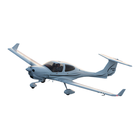
Поздравляем вас с приобретением нового самолета DIAMOND DA 40 NG.
Умелая эксплуатация самолета позволяет повысить как безопасность полета, так и удовольствие от управления самолетом. Просим вас перед эксплуатацией самолета DIAMOND DA 40 NG ознакомиться с его конструкцией и особенностями.
Эксплуатация самолета разрешается только в соответствии с настоящим Руководством по летной эксплуатации и установленными в нем эксплуатационными ограничениями.
Перед началом эксплуатации самолета пилот обязан внимательно ознакомиться с настоящим Руководством по летной эксплуатации.
Если вы приобрели самолет DIAMOND DA 40 NG, ранее бывший в эксплуатации, просим вас сообщить нам свой адрес, чтобы мы могли высылать вам документацию, необходимую для безопасной эксплуатации самолета.
Настоящий документ защищен авторским правом. Все сопутствующие права, в частности, права на перевод, перепечатку, передачу по радиоканалу, копирование фотомеханическими или аналогичными средствами, а также хранение в системах обработки данных полного или частичного содержания настоящего документа сохраняются за правообладателем.
Авторское право © DIAMOND AIRCRAFT INDUSTRIES GMBH N.A. Otto-Strasse 5
A-2700 Wiener Neustadt, Austria (Австрия) Телефон: +43-2622-26700 Факс: +43-2622-26780
Эл. почта: office@diamond-air.at
|
Док. № 6.01.15-E |
Ред. 1 |
15 марта 2011 г. |
Стр. 0 — 1 |

0.1 УТВЕРЖДЕНИЕ
Информация, приведенная в утвержденных разделах, утверждена EASA. Вся прочая информация утверждена DAI на основании выданного EASA свидетельства DOA № EASA.21J.052 в соответствии с положениями Части 21.
0.2 РЕГИСТРАЦИЯ ИЗМЕНЕНИЙ
Все изменения, вносимые в настоящее руководство, за исключением следующих:
•Временные редакции,
•изменения уровня модификации (Раздел 1.1),
•изменения весовых и центровочных данных (Раздел 6.3),
•изменения в Перечне установленного оборудования (Раздел 6.5) и
•изменения в Перечне дополнительной документации (Раздел 9.2), подлежат регистрации в приведенной ниже таблице.
Новый или измененный текст помечается черной вертикальной чертой на левом поле страницы с изменениями. В нижнем колонтитуле указываются номер и дата редакции.
При внесении изменений в страницы, на которых приводится информация, относящаяся к самолету с вашим серийным номером (уровень модификации самолета, весовые и центровочные данные, Перечень установленного оборудования, Перечень дополнительной документации), эту информацию необходимо вписать в новые страницы от руки.
Временные редакции используются для включения в РЛЭ информации о системах и оборудовании до следующей «постоянной» Редакции настоящего Руководства по летной эксплуатации. Если действие «постоянной» Редакции распространяется на область применения Обязательной или Необязательной рекомендации по внесению изменений в конструкцию (MÄM/OÄM), действие соответствующей Временной редакции в применимой части отменяется. Например, действие Редакции 5 распространяется на область применения Необязательной рекомендации OÄM 40-039. В этом случае Временная редакция TR-OÄM-40-039 заменяется «постоянной» Редакцией 5.
Титульные страницы Временных редакций (для Временных редакций) вставляются в настоящее руководство после его титульной страницы; все другие страницы вставляются перед соответствующими страницами настоящего РЛЭ.
|
Стр. 0 — 2 |
Ред. 1 |
15 марта 2011 г. |
Док. № 6.01.15-E |

Страница намеренно оставлена пустой.
|
Стр. 0 — 4 |
Ред. 1 |
15 марта 2011 г. |
Док. № 6.01.15-E |

0.3 ПЕРЕЧЕНЬ ДЕЙСТВУЮЩИХ СТРАНИЦ
|
Раздел |
Стр. |
Дата |
Раздел |
Стр. |
Дата |
|||
|
0 |
0-0 |
01 апреля 2010 г. |
1 |
1-1 |
15 марта 2011 г. |
|||
|
0-0a |
01 апреля 2010 г. |
1-2 |
15 марта 2011 г. |
|||||
|
0-1 |
15 марта 2011 г. |
1-3 |
15 марта 2011 г. |
|||||
|
0-2 |
15 марта 2011 г. |
1-4 |
15 марта 2011 г. |
|||||
|
0-3 |
15 марта 2011 г. |
1-5 |
15 марта 2011 г. |
|||||
|
0-4 |
15 марта 2011 г. |
1-6 |
15 марта 2011 г. |
|||||
|
0-5 |
15 марта 2011 г. |
1-7 |
15 марта 2011 г. |
|||||
|
0-6 |
15 марта 2011 г. |
1-8 |
15 марта 2011 г. |
|||||
|
0-7 |
15 марта 2011 г. |
1-9 |
15 марта 2011 г. |
|||||
|
0-8 |
15 марта 2011 г. |
1-10 |
15 марта 2011 г. |
|||||
|
0-9 |
15 марта 2011 г. |
1-11 |
15 марта 2011 г. |
|||||
|
0-10 |
15 марта 2011 г. |
1-12 |
15 марта 2011 г. |
|||||
|
0-11 |
15 марта 2011 г. |
1-13 |
15 марта 2011 г. |
|||||
|
0-12 |
15 марта 2011 г. |
1-14 |
15 марта 2011 г. |
|||||
|
0-13 |
15 марта 2011 г. |
1-15 |
15 марта 2011 г. |
|||||
|
0-14 |
15 марта 2011 г. |
1-16 |
15 марта 2011 г. |
|||||
|
1-17 |
15 марта 2011 г. |
|||||||
|
1-18 |
15 марта 2011 г. |
|||||||
|
1-19 |
15 марта 2011 г. |
|||||||
|
1-20 |
15 марта 2011 г. |
|||||||
|
Док. № 6.01.15-E |
Ред. 1 |
15 марта 2011 г. |
Стр. 0 — 5 |

2утв. 2-1 15 марта 2011 г.
утв. 2-2 15 марта 2011 г.
утв. 2-3 15 марта 2011 г.
утв. 2-4 15 марта 2011 г.
утв. 2-5 15 марта 2011 г.
утв. 2-6 15 марта 2011 г.
утв. 2-7 15 марта 2011 г.
утв. 2-8 15 марта 2011 г.
утв. 2-9 15 марта 2011 г.
утв. 2-10 15 марта 2011 г.
утв. 2-11 15 марта 2011 г.
утв. 2-12 15 марта 2011 г.
утв. 2-13 15 марта 2011 г.
утв. 2-14 15 марта 2011 г.
утв. 2-15 15 марта 2011 г.
утв. 2-16 15 марта 2011 г.
утв. 2-17 15 марта 2011 г.
утв. 2-18 15 марта 2011 г.
утв. 2-19 15 марта 2011 г.
утв. 2-20 15 марта 2011 г.
утв. 2-21 15 марта 2011 г.
утв. 2-22 15 марта 2011 г.
утв. 2-23 15 марта 2011 г.
утв. 2-24 15 марта 2011 г.
утв. 2-25 15 марта 2011 г.
утв. 2-26 15 марта 2011 г.
утв. 2-27 15 марта 2011 г.
2утв. 2-28 15 марта 2011 г.
утв. 2-29 15 марта 2011 г.
утв. 2-30 15 марта 2011 г.
утв. 2-31 15 марта 2011 г.
утв. 2-32 15 марта 2011 г.
|
Стр. 0 — 6 |
Ред. 1 |
15 марта 2011 г. |
Док. № 6.01.15-E |
- Manuals
- Brands
- Diamond Aircraft Manuals
- Tools
- DA 40 NG
- Airplane maintenance manual
-
Contents
-
Table of Contents
-
Troubleshooting
-
Bookmarks
Related Manuals for Diamond Aircraft DA 40 NG
Summary of Contents for Diamond Aircraft DA 40 NG
-
Page 1
AIRCRAFT DA 40 NG AIRPLANE MAINTENANCE MANUAL Copyright © by DIAMOND AIRCRAFT INDUSTRIES, Wiener Neustadt, Austria… -
Page 2
Introduction DA 40 NG AMM AIRCRAFT This document is protected by copyright. All associated rights, in particular those of translation, reprinting, radio transmission, reproduction by photo-mechanical or similar means and storing in data processing facilities, in whole or part, are reserved. -
Page 3
Time Limits and Maintenance Checks 05-10 Time Limits 05-20 Scheduled Maintenance Checks 05-21 Flight-Line Checks 05-25 Drain Holes Inspection Checklist and Report 05-28 Maintenance Checklist DA 40 NG 05-50 Unscheduled Maintenance Checks 06-00 Dimensions and Areas 07-00 Lifting and Shoring 07-10 Jacking 08-00… -
Page 4
Table of Contents DA 40 NG AMM AIRCRAFT 21-00 Air Conditioning, Heating and Ventilation 21-50 Cooling 21-51 Cooling (OÄM 40-316/i or later installed) 22-00 Auto Flight 22-10 Autopilot, GFC 700 22-11 Autopilot, KAP 140 23-00 Communications 23-10 Speech Communication with G1000 System Installed… -
Page 5
Table of Contents DA 40 NG AMM AIRCRAFT 32-00 Landing Gear 32-10 Main Landing Gear 32-20 Nose Landing Gear 32-40 Wheels and Brakes 33-00 Lights 33-10 Lights — Flight Compartment 33-40 Exterior Lights 34-00 Navigation 34-10 Flight Environment Data 34-20… -
Page 6
Table of Contents DA 40 NG AMM AIRCRAFT 56-00 Windows 56-10 Flight Compartment Windows 57-00 Wings 57-10 Wing Structure 57-50 Flaps 57-60 Aileron 61-00 Propeller 61-10 Propeller Assembly 61-20 Propeller Control 71-00 Power Plant 71-10 Engine Cowling 71-20 Engine Mounting… -
Page 7
Record of Revision DA 40 NG AMM AIRCRAFT Record of Revision 1. Record of Revision Use this check list to record and control all of the revisions which you put in this Airplane Maintenance Manual (AMM). Put the affected pages of the revision into the AMM as soon as you get them. Remove and destroy the pages which are superseded. -
Page 8
Record of Revision DA 40 NG AMM AIRCRAFT 2. Record of Incorporated Temporary Revisions The following Temporary Revisions are incorporated into the DA 40 NG AMM by Revision 1: Temporary Revision Number Description of Temporary Revision AMM-TR-MÄM 40-434 Cowling Redesign AMM-TR-MÄM 40-434/a… -
Page 9
Record of Revision DA 40 NG AMM AIRCRAFT The following Temporary Revisions are incorporated into the DA 40 NG AMM by Revision 2: Temporary Revision Number Description of Temporary Revision AMM-TR-MÄM 40-502/a & Replacement of Charged Air Hoses with Tube AMM-TR-MÄM 40-506/a… -
Page 10
Record of Revision DA 40 NG AMM AIRCRAFT The following Temporary Revisions are incorporated into the DA 40 NG AMM by Revision 3: Temporary Revision Number Description of Temporary Revision AMM-TR-MÄM 40-561 New GFC 700 Autopilot Hardware AMM-TR-MÄM 40-619 Passenger Door Improvement AMM-TR-MÄM 40-635… -
Page 11
Record of Revision DA 40 NG AMM AIRCRAFT Temporary Revision Number Description of Temporary Revision AMM-TR-MÄM 40-865 Conservation of Exterior Parts AMM-TR-MÄM 40-868 Garmin Hard- und Software Upgrade I AMM-TR-MÄM 40-874 Engine Oils AMM-TR-MÄM 40-899 Improved Air Charge Hose AMM-TR-OÄM 40-251 Electrical Pedal Adjustment AMM-TR-OÄM 40-258… -
Page 12
Record of Revision DA 40 NG AMM AIRCRAFT Intentionally left blank Page x Doc # 6.02.15 01 Sep 2017 Rev. 3… -
Page 13
List of Effective Pages DA 40 NG AMM AIRCRAFT LIST OF EFFECTIVE PAGES 1. General The list of effective pages uses this abbreviation: Table of Contents. Record of Revisions. LOEP List of Effective Pages. All Sections have a Title Page and a Table of Contents. The TOC can have one page or it can have many pages. -
Page 14
List of Effective Pages DA 40 NG AMM AIRCRAFT Chapter Page Revision Chapter Page Revision Chapter Page Revision Section Date Section Date Section Date 03-00 01 Sep 2017 05-10 01 Sep 2017 05-28-00 01 Sep 2017 03-00 01 Sep 2017… -
Page 15
List of Effective Pages DA 40 NG AMM AIRCRAFT Chapter Page Revision Chapter Page Revision Chapter Page Revision Section Date Section Date Section Date 05-28-50 01 Sep 2017 05-50 01 Sep 2017 08-00 Title 1 01 Sep 2017 05-50 01 Sep 2017… -
Page 16
List of Effective Pages DA 40 NG AMM AIRCRAFT Chapter Page Revision Chapter Page Revision Chapter Page Revision Section Date Section Date Section Date 09-00 01 Sep 2017 11-20 01 Sep 2017 12-10 01 Sep 2017 09-10 01 Sep 2017… -
Page 17
List of Effective Pages DA 40 NG AMM AIRCRAFT Chapter Page Revision Chapter Page Revision Chapter Page Revision Section Date Section Date Section Date 20-00 TOC 1 01 Sep 2017 21-00 01 Sep 2017 21-51 01 Sep 2017 21-00 01 Sep 2017… -
Page 18
List of Effective Pages DA 40 NG AMM AIRCRAFT Chapter Page Revision Chapter Page Revision Chapter Page Revision Section Date Section Date Section Date 22-10 01 Sep 2017 22-11 01 Sep 2017 23-10 01 Sep 2017 22-10 01 Sep 2017… -
Page 19
List of Effective Pages DA 40 NG AMM AIRCRAFT Chapter Page Revision Chapter Page Revision Chapter Page Revision Section Date Section Date Section Date 23-51 01 Sep 2017 24-30 01 Sep 2017 24-33 01 Sep 2017 24-30 01 Sep 2017… -
Page 20
List of Effective Pages DA 40 NG AMM AIRCRAFT Chapter Page Revision Chapter Page Revision Chapter Page Revision Section Date Section Date Section Date 24-60 01 Sep 2017 25-10 01 Sep 2017 25-60 01 Sep 2017 24-60 01 Sep 2017… -
Page 21
List of Effective Pages DA 40 NG AMM AIRCRAFT Chapter Page Revision Chapter Page Revision Chapter Page Revision Section Date Section Date Section Date 27-10 01 Sep 2017 27-20 01 Sep 2017 27-38 01 Sep 2017 27-20 01 Sep 2017… -
Page 22
List of Effective Pages DA 40 NG AMM AIRCRAFT Chapter Page Revision Chapter Page Revision Chapter Page Revision Section Date Section Date Section Date 27-50 01 Sep 2017 28-10 01 Sep 2017 28-20 01 Sep 2017 27-50 01 Sep 2017… -
Page 23
List of Effective Pages DA 40 NG AMM AIRCRAFT Chapter Page Revision Chapter Page Revision Chapter Page Revision Section Date Section Date Section Date 28-40 01 Sep 2017 31-20 01 Sep 2017 31-40 01 Sep 2017 31-40 01 Sep 2017… -
Page 24
List of Effective Pages DA 40 NG AMM AIRCRAFT Chapter Page Revision Chapter Page Revision Chapter Page Revision Section Date Section Date Section Date 32-10 01 Sep 2017 32-20 01 Sep 2017 32-40 01 Sep 2017 32-10 01 Sep 2017… -
Page 25
List of Effective Pages DA 40 NG AMM AIRCRAFT Chapter Page Revision Chapter Page Revision Chapter Page Revision Section Date Section Date Section Date 33-40 01 Sep 2017 34-00 01 Sep 2017 34-22 01 Sep 2017 34-10 01 Sep 2017… -
Page 26
List of Effective Pages DA 40 NG AMM AIRCRAFT Chapter Page Revision Chapter Page Revision Chapter Page Revision Section Date Section Date Section Date 34-42 01 Sep 2017 34-56 01 Sep 2017 51-20 01 Sep 2017 34-42 01 Sep 2017… -
Page 27
List of Effective Pages DA 40 NG AMM AIRCRAFT Chapter Page Revision Chapter Page Revision Chapter Page Revision Section Date Section Date Section Date 51-30 01 Sep 2017 52-00 TOC 2 01 Sep 2017 52-10 01 Sep 2017 52-00 01 Sep 2017… -
Page 28
List of Effective Pages DA 40 NG AMM AIRCRAFT Chapter Page Revision Chapter Page Revision Chapter Page Revision Section Date Section Date Section Date 53-10 01 Sep 2017 55-20 01 Sep 2017 56-10 01 Sep 2017 53-10 01 Sep 2017… -
Page 29
List of Effective Pages DA 40 NG AMM AIRCRAFT Chapter Page Revision Chapter Page Revision Chapter Page Revision Section Date Section Date Section Date 57-10 01 Sep 2017 61-10 01 Sep 2017 61-20 01 Sep 2017 61-10 01 Sep 2017… -
Page 30
List of Effective Pages DA 40 NG AMM AIRCRAFT Chapter Page Revision Chapter Page Revision Chapter Page Revision Section Date Section Date Section Date 71-00 01 Sep 2017 71-60 01 Sep 2017 72-00 01 Sep 2017 71-00 01 Sep 2017… -
Page 31
List of Effective Pages DA 40 NG AMM AIRCRAFT Chapter Page Revision Chapter Page Revision Chapter Page Revision Section Date Section Date Section Date 75-00 01 Sep 2017 76-00 TOC 2 01 Sep 2017 77-40 01 Sep 2017 76-00 01 Sep 2017… -
Page 32
List of Effective Pages DA 40 NG AMM AIRCRAFT Chapter Page Revision Chapter Page Revision Chapter Page Revision Section Date Section Date Section Date 78-00 01 Sep 2017 81-00 TOC 1 01 Sep 2017 92-00 01 Sep 2017 79-00 Title 1 01 Sep 2017… -
Page 33
Introduction DA 40 NG AMM AIRCRAFT CHAPTER 01 INTRODUCTION Doc # 6.02.15 Page 1 01-TITLE Rev. 3 01 Sep 2017… -
Page 34
Introduction DA 40 NG AMM AIRCRAFT Intentionally left blank Page 2 Doc # 6.02.15 01-TITLE Rev. 3 01 Sep 2017… -
Page 35: Table Of Contents
Introduction DA 40 NG AMM AIRCRAFT TABLE OF CONTENTS CHAPTER 01 INTRODUCTION General …………1 Revision Service .
-
Page 36
Introduction DA 40 NG AMM AIRCRAFT Intentionally left blank Page 2 Doc # 6.02.15 01-CONTENTS Rev. 3 01 Sep 2017… -
Page 37: Introduction
This Airplane Maintenance Manual contains the data necessary to do the maintenance of the DA 40 NG. It contains a full description of the systems, trouble shooting procedures, removal and installation procedures and maintenance instructions. It does not contain maintenance data for components removed from the airplane (maintenance shop data).
-
Page 38: Manual Configuration
Introduction DA 40 NG AMM AIRCRAFT 4. Manual Configuration This manual is written using the regulations of the Air Transport Association of America Specification 100 (ATA 100). Each system is given a chapter number from the ATA 100. Where applicable, a chapter contains sections for each sub-system.
-
Page 39
Introduction DA 40 NG AMM AIRCRAFT A. The ATA100 Numbering System The ATA100 numbering system uses 3 pairs of numbers, for example: 57-50-xx Chapter / System Section / Subsystem Unit / Subject Number (Wings) (Flaps) (Not normally used) The first pair of numbers show the system. System 57 is the Wings. Chapter 57 contains the data for the wings. -
Page 40
Introduction DA 40 NG AMM AIRCRAFT The main contents of each group of chapters is given below: (1) Group A — Introduction Chapter 1 tells you about the Airplane Maintenance Manual, and Chapter 2 tells you how to use the Airplane Maintenance Manual. -
Page 41
Introduction DA 40 NG AMM AIRCRAFT (5) Group E — Propeller Chapter 61 contains the maintenance procedures for the propeller. Refer to the propeller manufacturer’s manual for other data. (6) Group F — Power Plant This group of chapters describes the engine and its systems which make the Power Plant. It contains the maintenance procedures for maintenance on the airplane. -
Page 42: Page Numbering System
Introduction DA 40 NG AMM AIRCRAFT 5. Page Numbering System This manual uses the ATA 100 page block-numbering system. The page number is at the bottom on the outer edge. It is adjacent to the chapter/section number. Each topic in a section has numbers from these page blocks: Description and Operation — Pages 1 to 99.
-
Page 43
Manual Organization DA 40 NG AMM AIRCRAFT CHAPTER 02 ORGANIZATION AND HANDLING OF THE MANUAL Doc # 6.02.15 Page 1 02-TITLE Rev. 3 01 Sep 2017… -
Page 44
Manual Organization DA 40 NG AMM AIRCRAFT Intentionally left blank Page 2 Doc # 6.02.15 02-TITLE Rev. 3 01 Sep 2017… -
Page 45
Manual Organization DA 40 NG AMM AIRCRAFT TABLE OF CONTENTS CHAPTER 02 ORGANIZATION AND HANDLING OF THE MANUAL General …………1 Applicability . -
Page 46
Manual Organization DA 40 NG AMM AIRCRAFT Intentionally left blank Page 2 Doc # 6.02.15 02-CONTENTS Rev. 3 01 Sep 2017… -
Page 47: Organization And Handling Of The Manual
Manual Organization DA 40 NG AMM AIRCRAFT CHAPTER 02 ORGANIZATION AND HANDLING OF THE MANUAL 1. General For data about a system, look in the list of chapters and find the chapter number. The first page of each chapter after the title page shows the contents.
-
Page 48: Service Bulletins
Manual Organization DA 40 NG AMM AIRCRAFT 5. Service Bulletins Service Bulletins get issued when necessary. They give the operator more information on inspections, maintenance, repairs or modifications. Service Bulletins have 4 categories: A. Alert Service Bulletins Alert Service Bulletins are issued if there is an immediate danger (risk of damage or total loss).
-
Page 49: Service Information
Manual Organization DA 40 NG AMM AIRCRAFT 6. Service Information A Service Information tells the operator about permitted installations or provided information to installed or additional equipment. It also gives the applicable technical data. 7. Concession-Reports and Non-Conformance-Reports Concession- and Non-Conformance-Reports are tools to approve and document deviations from the standard manufacturing processes during construction and assembly of an individual airplane (for example, handling of a mis-drilled hole in the fuselage).
-
Page 50: Abbreviations
Manual Organization DA 40 NG AMM AIRCRAFT 8. Abbreviations Where possible, the abbreviations used correspond with the related regulations. Ampere Anti-Collision Light Automatic Direction Finder A.M.E. Aircraft Maintenance Engineer Ampere-Hour A&P Aircraft and Power Plant Mechanic Airspeed Indicator Controller Area Network…
-
Page 51
Manual Organization DA 40 NG AMM AIRCRAFT Secondary Engine Display Serial Number Time Between Overhaul TSMOH Time Since Major Overhaul Ultra High Frequency TTSN Total Time Since New TTSO Total Time Since Overhaul Volt Visual Flight Rules Very High Frequency… -
Page 52: Conversion Factors And Abbreviations
Manual Organization DA 40 NG AMM AIRCRAFT 9. Conversion Factors and Abbreviations Dimension Conversion Factor Conversion Factor Unit [Abbreviation] SI to US/Imperial US/Imperial to SI Length [m] / 0.3048 = [ft] Meter [m] [mm] / 25.4 = [in] Millimeter [mm] [km] / 1.852 = [nm]…
-
Page 53
Manual Organization DA 40 NG AMM AIRCRAFT Dimension Conversion Factor Conversion Factor Unit [Abbreviation] SI to US/Imperial US/Imperial to SI Force or Weight Newton [N] [N] / 4.448 = [lb] Decanewton [daN] [daN] / 0.4448 = [lb] Pound [lb] [lb] x 4.448 = [N] [lb] x 0.4448 = [daN]… -
Page 54: Torque Conversion Graphs
Manual Organization DA 40 NG AMM AIRCRAFT 10. Torque Conversion Graphs Use Figure 1 for conversion of torque values Nm — lbf.ft. Use Figure 2 for conversion of Nm — lbf.in. 10 15 20 25 30 45 50 55 60 65 70 75 80 85 90 95 100 Newton.Metre (Nm)
-
Page 55
Manual Organization DA 40 NG AMM AIRCRAFT 0.5 1.0 1.5 2.0 2.5 3.0 4.5 5.0 5.5 6.0 6.5 7.0 7.5 8.0 8.5 9.0 9.5 10.0 Newton.Metre (Nm) Figure 2: Nm — lbf.in. Find the Nm value on the horizontal axis. Move vertically to the solid black diagonal line. Then move horizontally to the vertical axis. -
Page 56
Manual Organization DA 40 NG AMM AIRCRAFT Intentionally left blank Page 10 Doc # 6.02.15 02-00-00 01 Sep 2017 Rev. 3… -
Page 57
General Description DA 40 NG AMM AIRCRAFT CHAPTER 03 GENERAL DESCRIPTION OF THE AIRPLANE Doc # 6.02.15 Page 1 03-TITLE Rev. 3 01 Sep 2017… -
Page 58
General Description DA 40 NG AMM AIRCRAFT Intentionally left blank Page 2 Doc # 6.02.15 03-TITLE Rev. 3 01 Sep 2017… -
Page 59
General Description DA 40 NG AMM AIRCRAFT TABLE OF CONTENTS CHAPTER 03 GENERAL DESCRIPTION OF THE AIRPLANE General …………1 Description . -
Page 60
General Description DA 40 NG AMM AIRCRAFT Intentionally left blank Page 2 Doc # 6.02.15 03-CONTENTS Rev. 3 01 Sep 2017… -
Page 61: General
DA 40 NG airplane. 2. Description The DA 40 NG is a single-engine, four seat, low-wing monoplane. It has a cantilever wing and a ‘T’ tail. The airplane structure is fiber-reinforced plastic composite. This gives a very strong but light structure.
-
Page 62
The nose leg attaches to the forward fuselage. Each main wheel has a disc brake on the inside. Hydraulic pressure operates each disc brake. The flight control system uses conventional ailerons, elevator and rudder. The DA 40 NG has two control sticks and two rudder pedal assemblies to operate the primary flight-controls. Push-pull rods operate the ailerons and elevator. -
Page 63
A starter key controls the engine starter motor. It also serves as ELECTRIC MASTER key switch. The DA 40 NG has a full range of flight instruments. These include Pitot/static instruments to show airspeed and altitude, as well as electrically driven instruments to show direction. If the G1000 system is installed most indications are shown on the G1000 and only the backup instruments are installed on the instrument panel. -
Page 64: Equipment Data
AIRCRAFT 3. Equipment Data The table below gives you the name and address of the manufacturers who supply systems and/or equipment for the DA 40 NG. This will help you get more data on a system and/or equipment. Equipment/System Address…
-
Page 65
General Description DA 40 NG AMM AIRCRAFT Equipment/System Address Chapter Autopilot System Bendix/King (if KAP 140 A/P is installed): 400 North Rogers Road Olathe, Kansas 66062-1212 Tel: (913) 782-0400 (USA and Canada) (913) 782-0700 (other countries) Website: www.bendixking.com Battery: Concorde Battery Corp. -
Page 66
General Description DA 40 NG AMM AIRCRAFT Equipment/System Address Chapter Backup Attitude Gyro: Mid-Continent Instrument Co., Inc. 7706 E, Osie, Wichita, Kansas 67207 Tel: (316) 683-5619 Fax: (316) 683-1861 Website: www.mcico.com Wheels and Brakes: Parker Hannifin Corporation Aircraft Wheel and Brake Division… -
Page 67: Handling Of Identification Data
General Description DA 40 NG AMM AIRCRAFT Equipment/System Address Chapter Austro Engines E4-A Engine: Austro Engine GmbH Rudolf Diesel-Str. 11 A-2700 Wiener Neustadt Austria Tel: +43 (2622) 23 000 Fax: +43 (2622) 23 000 — 2711 Homepage: www.austroengine.at 4. Handling of Identification Data…
-
Page 68
General Description DA 40 NG AMM AIRCRAFT Intentionally left blank Page 8 Doc # 6.02.15 03-00-00 01 Sep 2017 Rev. 3… -
Page 69
Airworthiness DA 40 NG AMM Limitations CHAPTER 04 AIRWORTHINESS LIMITATIONS Doc # 6.02.15 Page 1 04-TITLE Rev. 3 01 Sep 2017… -
Page 70
Airworthiness DA 40 NG AMM Limitations AIRCRAFT Intentionally left blank Page 2 Doc # 6.02.15 04-TITLE Rev. 3 01 Sep 2017… -
Page 71
Airworthiness DA 40 NG AMM Limitations TABLE OF CONTENTS CHAPTER 04 AIRWORTHINESS LIMITATIONS Airworthiness Limitations ……….3 Continued Airworthiness . -
Page 72
Airworthiness DA 40 NG AMM Limitations AIRCRAFT Intentionally left blank Page 2 Doc # 6.02.15 04-CONTENTS Rev. 3 01 Sep 2017… -
Page 73
Airworthiness DA 40 NG AMM Limitations CHAPTER 04 AIRWORTHINESS LIMITATIONS THIS AIRWORTHINESS LIMITATIONS SECTION IS APPROVED BY EUROPEAN AVIATION SAFETY AGENCY (EASA) IN ACCORDANCE WITH THE APPLICABLE CERTIFICATION PROCEDURES AND THE TYPE CERTIFICATION BASIS. IT SPECIFIES THE AIRWORTHINESS LIMITATIONS REQUIRED BY JAR 23. -
Page 74
Airworthiness DA 40 NG AMM Limitations AIRCRAFT Intentionally left blank Page 2 Doc # 6.02.15 04-00-00 01 Sep 2017 Rev. 3… -
Page 75
Note: Regular inspections of the airplane including replacement and overhaul of certain components are required to ensure Continued Airworthiness of the DA 40 NG. For possible airworthiness limitations of engine, propeller, components and vendor equipment refer to the applicable Maintenance data as listed in Section 05-00. -
Page 76
(2) Life Time Limit / Structure Checks There is no structural life limit. Note: The DA 40 NG has been designed and tested under a ‘damage tolerant structure’ philosophy. Therefore the structural inspections given in Chapter 05 cover all required structure checks. -
Page 77
Limitations C. Color of Airframe It is mandatory to paint the DA 40 NG white as described in Chapter 51 of this manual. This will prevent the temperature of the structure from becoming too high. Examples of approves shades are:… -
Page 78
Airworthiness DA 40 NG AMM Limitations AIRCRAFT Intentionally left blank Page 6 Doc # 6.02.15 04-00-00 01 Sep 2017 Rev. 3… -
Page 79
Time Limits and DA 40 NG AMM Maintenance Checks AIRCRAFT CHAPTER 05 TIME LIMITS AND MAINTENANCE CHECKS Doc # 6.02.15 Page 1 05-TITLE Rev. 3 01 Sep 2017… -
Page 80
Time Limits and DA 40 NG AMM Maintenance Checks AIRCRAFT Intentionally left blank Page 2 Doc # 6.02.15 05-TITLE Rev. 3 01 Sep 2017… -
Page 81
Time Limits and DA 40 NG AMM Maintenance Checks AIRCRAFT TABLE OF CONTENTS CHAPTER 05 TIME LIMITS AND MAINTENANCE CHECKS General …………1 Chapter Configuration . -
Page 82
Drain Holes Inspection Checklist ……..1 Section 05-28 Maintenance Checklist DA 40 NG Section 05-28-00 Maintenance Checklist Engine General . -
Page 83
Time Limits and DA 40 NG AMM Maintenance Checks AIRCRAFT Section 05-28-91 Engine Ground Test Report Engine Ground Test Report ……… . 1… -
Page 84
Time Limits and DA 40 NG AMM Maintenance Checks AIRCRAFT Intentionally left blank Page 4 Doc # 6.02.15 05-CONTENTS 01 Sep 2017 Rev. 3… -
Page 85: Time Limits And Maintenance Checks
TIME LIMITS AND MAINTENANCE CHECKS 1. General This Chapter will help to do the maintenance of the DA 40 NG correctly. Refer to Sections 04-00 and 05-00 for maintenance and inspections. The times given in this Chapter are times recommended by the airplane manufacturer. Do the scheduled maintenance at the given times, because they are the minimum required to keep the airplane in a good technical condition.
-
Page 86
Maintenance Checks AIRCRAFT E. Section 05-28 Section 05-28 contains the Maintenance Checklist for the DA 40 NG airplane. The Section is subdivided into engine and airframe sections and provides checklists for the engines and the airframe and the corresponding reports. -
Page 87
Time Limits and DA 40 NG AMM Maintenance Checks AIRCRAFT G. Referenced Maintenance Data Use latest revision of referenced maintenance data. Supplier Document Name Document No. Artex Installation and Maintenance Manual for the 570-1600 ME406 ELT Austro Engine Austro Engine Operation Manual AE300 E4.01.01… -
Page 88: Definitions
Time Limits and DA 40 NG AMM Maintenance Checks AIRCRAFT 3. Definitions In this Airplane Maintenance Manual, the words that follow have special meanings: Adjust. To put to a specified position or condition. For example, adjust the clearance to 1 mm.
-
Page 89
Time Limits and DA 40 NG AMM Maintenance Checks AIRCRAFT Task. An assigned work or a procedure. For example, each step of the task has an identification letter. Test. That which you do when you operate or examine an item to make sure that it agrees with the applicable specifications. -
Page 90
Time Limits and DA 40 NG AMM Maintenance Checks AIRCRAFT Intentionally left blank Page 6 Doc # 6.02.15 05-00-00 01 Sep 2017 Rev. 3… -
Page 91: Time Limits
Time Limits and DA 40 NG AMM Maintenance Checks AIRCRAFT Section 05-10 Time Limits 1. General This Section lists time limits for scheduled Maintenance on airframe and components, and replacement or overhaul of components directly or by reference. Obey the time limits in this Section to keep the airplane in a technical good condition.
-
Page 92
Time Limits and DA 40 NG AMM Maintenance Checks AIRCRAFT If an inspection is carried out earlier than allowed by the specified tolerance, all subsequent inspection intervals are counted from that inspection. For example: If the 100 hour inspection was done at 83 hours, the next inspection must be done at 183 hours. -
Page 93: Component Time Limits
Time Limits and DA 40 NG AMM Maintenance Checks AIRCRAFT 3. Component Time Limits A. Maintenance Requirements The following table lists airplane components and systems which require overhaul or specific checks. Where an interval is given in both flight time and calendar years, the limit which is reached first must be used.
-
Page 94
Time Limits and DA 40 NG AMM Maintenance Checks AIRCRAFT Kind Interval Component Maintenance Requirement hrs. yrs. Ope. Fire extinguisher. Overhaul. ± 60 days Check valve in front of fuel Clean check valve mesh. 1000 transfer pump. ± 50 Pitot-static system. -
Page 95
Time Limits and DA 40 NG AMM Maintenance Checks AIRCRAFT B. Airplane Life-Limited Components The following table lists life limited airplane components which must be replaced at a specific time. Where an interval is given in both flight time and calendar years, the limit which is reached first must be applied. -
Page 96
Time Limits and DA 40 NG AMM Maintenance Checks AIRCRAFT Replacement Time Kind of Component Operation hrs. yrs. Co-incident Fuel bypass valve. with engine TBO. Fuel tank vent hoses. 8 ± 60 days Fuel filter element. 100 ± 10 1 ± 30 days… -
Page 97: Component Time Tracking
Time Limits and DA 40 NG AMM Maintenance Checks AIRCRAFT 4. Component Time Tracking To make sure that components overhaul/replacement is done at the correct time you must record the data that follows in the Airplane Maintenance Log for each component requiring overhaul/replacement: Serial Number.
-
Page 98
Time Limits and DA 40 NG AMM Maintenance Checks AIRCRAFT Intentionally left blank Page 8 Doc # 6.02.15 05-10-00 01 Sep 2017 Rev. 3… -
Page 99: Scheduled Maintenance Checks
Time Limits and DA 40 NG AMM Maintenance Checks AIRCRAFT Section 05-20 Scheduled Maintenance Checks 1. General Do the scheduled maintenance checks in this Section at the intervals (flight hours and calendar time) stated in Section 05-10, Paragraph 3. Note: Only persons or maintenance organizations authorized by national Regulatory Authorities of the country where the airplane is registered may do these checks.
-
Page 100: Maintenance Checklist Organization
Time Limits and DA 40 NG AMM Maintenance Checks AIRCRAFT 2. Maintenance Checklist Organization Do the scheduled maintenance checks with reference to the Maintenance Checklist in this Section. Before starting a check, complete the requirements of Paragraphs 2 and 3 of the checklist. In parallel do the scheduled drain hole checks with reference to the Drain Holes Inspection Checklist and Report.
-
Page 101: Major Structural Inspection
The Major Structural Inspection (MSI) is an important part of the infinite lifetime concept of the DA 40 NG. It is required to prove the structural integrity of the airframe. It must be carried out at the intervals shown in Section 05-20.
-
Page 102
Time Limits and DA 40 NG AMM Maintenance Checks AIRCRAFT Intentionally left blank Page 4 Doc # 6.02.15 05-20-00 01 Sep 2017 Rev. 3… -
Page 103: Flight-Line Checks
DO ALL THE STEPS OF THE DAILY CHECK CAREFULLY. ACCIDENTS CAN OCCUR IF THE DAILY CHECK IS NOT DONE CORRECTLY. The schedule for the pilot’s daily check is in the Airplane Flight Manual for the DA 40 NG. 3. Post-Flight Check Do the post-flight check after the last flight of the day.
-
Page 104
Time Limits and DA 40 NG AMM Maintenance Checks AIRCRAFT Intentionally left blank Page 2 Doc # 6.02.15 05-21-00 01 Sep 2017 Rev. 3… -
Page 105: Drain Holes Inspection Checklist And Report
Time Limits and DA 40 NG AMM Maintenance Checks AIRCRAFT Section 05-25 Drain Holes Inspection Checklist and Report 1. General Do a check of the drain holes. The drain holes must not be blocked by dirt or other residues. Make sure to remove all foreign objects and clean the drain holes to their full diameter.
-
Page 106: Drain Holes Inspection Checklist
Time Limits and DA 40 NG AMM Maintenance Checks AIRCRAFT Drain Holes Inspection Checklist Drain Hole Location Ref. Hours Initials 1.14 On lowest point of the fin 1.15 On lowest point of the EPC connector 1.16 In rudder bolt mounting shell (on top of the rudder) 1.17…
-
Page 107
Time Limits and DA 40 NG AMM Maintenance Checks AIRCRAFT Drain Holes Inspection Checklist Ref. Drain Hole Location Hours Initials ELEVATOR TRIM TAB 5.01 Lower shell, leading edge section, LH & RH 5.02 Lower shell, in front of trailing edge bonding, LH & RH RUDDER 6.01… -
Page 108
Time Limits and DA 40 NG AMM Maintenance Checks AIRCRAFT 1.22 1.16 To be checked only in production or repair 1.18 1.15 1.17 1.20 1.21 1.19 1.26 1.23 1.25 1.11 1.14 1.12 To be checked only Maintenance Access in production or repair… -
Page 109
Time Limits and DA 40 NG AMM Maintenance Checks AIRCRAFT 1.02 1.10 1.06 1.09 1.01 1.04 1.07 1.13 1.24 1.03 1.05 1.08 1.13 1.01 1.04 1.06 1.10 1.09 1.02 100 Hours Check Horizontal Drainage Hole 200 Hours Check Vertical Drainage Hole… -
Page 110
Time Limits and DA 40 NG AMM Maintenance Checks AIRCRAFT 2.02 2.01 2.01 2.02 100 Hours Check Horizontal Drainage Hole 200 Hours Check Vertical Drainage Hole 2000 Hours Check Exterior Drainage Hole Drainage Hole Inside the Structure Figure 3: Drain Holes Canopy Page 6 Doc # 6.02.15… -
Page 111
Time Limits and DA 40 NG AMM Maintenance Checks AIRCRAFT 2.03 100 Hours Check Horizontal Drainage Hole 200 Hours Check Vertical Drainage Hole 2000 Hours Check Exterior Drainage Hole Drainage Hole Inside the Structure Figure 4: Drain Holes Passenger Door Doc # 6.02.15… -
Page 112
Time Limits and DA 40 NG AMM Maintenance Checks AIRCRAFT 3.07 3.02 3.07 3.06 3.06 3.09 3.09 3.05 3.01 3.05 3.08 3.08 3.04 3.04 4.01 4.01 4.02 4.02 3.03 3.07 5.01 5.01 5.02 5.02 100 Hours Check Horizontal Drainage Hole… -
Page 113
Time Limits and DA 40 NG AMM Maintenance Checks AIRCRAFT View on Arrow A 6.01 6.01 100 Hours Check Horizontal Drainage Hole 200 Hours Check Vertical Drainage Hole 2000 Hours Check Exterior Drainage Hole Drainage Hole Inside the Structure Figure 6: Drain Holes Rudder Doc # 6.02.15… -
Page 114
Time Limits and DA 40 NG AMM Maintenance Checks AIRCRAFT Maintenance Access Maintenance Access 7.11 7.09 7.08 7.07 7.12 7.10 7.03 7.01 9.02 7.12 7.04 7.09 7.09 7.08 7.07 9.04 7.05 7.06 9.03 7.02 9.01 8.01 View A 7.06 7.09… -
Page 115: Maintenance Checklist Da 40 Ng
Time Limits and DA 40 NG AMM Maintenance Checks AIRCRAFT Section 05-28 Maintenance Checklist DA 40 NG Section 05-28-00 Maintenance Checklist Engine 1. General Enter the applicable data in the blocks below: Registration _________________ Date _________________ Airplane S/N _________________ Engine S/N…
-
Page 116: Preparation
Time Limits and DA 40 NG AMM Maintenance Checks AIRCRAFT 2. Preparation CAUTION: OBSERVE THE COMPONENT TIME LIMITS STATED IN SECTIONS 04-00 AND 05-10 OF THIS AIRPLANE MAINTENANCE MANUAL. Do the following items before you start the applicable check: Interval (Flight Hours)
-
Page 117: Engine Ground Test
Time Limits and DA 40 NG AMM Maintenance Checks AIRCRAFT 3. Engine Ground Test Do an engine ground test as follows (complete a copy of the Engine Ground Test Record as part of the engine ground test. (Refer to Section 05-28-91):…
-
Page 118: Engine Maintenance Checklist
Time Limits and DA 40 NG AMM Maintenance Checks AIRCRAFT 4. Engine Maintenance Checklist 100 hr items marked X* apply to US registered airplanes only Interval Inspection Items, Engine 100 200 1000 2000 Time Initials WARNING: MAKE SURE THE EXHAUST SYSTEM IS COOL BEFORE YOU DO MAINTENANCE ON THE ENGINE.
-
Page 119
Time Limits and DA 40 NG AMM Maintenance Checks AIRCRAFT 100 hr items marked X* apply to US registered airplanes only Interval Inspection Items, Engine 100 200 1000 2000 Time Initials Verify proper mixture ratio of the coolant. Refer to the AE Maintenance Manual, latest revision. -
Page 120
Time Limits and DA 40 NG AMM Maintenance Checks AIRCRAFT 100 hr items marked X* apply to US registered airplanes only Interval Inspection Items, Engine 100 200 1000 2000 Time Initials Examine the bonding cables and their connectors in the engine area: S Look specially for rub marks and damage. -
Page 121
Time Limits and DA 40 NG AMM Maintenance Checks AIRCRAFT 100 hr items marked X* apply to US registered airplanes only Interval Inspection Items, Engine 100 200 1000 2000 Time Initials Examine the air intake and turbo-charging system: Look specially for signs of chafing or damage on these items: S Air filter. -
Page 122
Time Limits and DA 40 NG AMM Maintenance Checks AIRCRAFT 100 hr items marked X* apply to US registered airplanes only Interval Inspection Items, Engine 100 200 1000 2000 Time Initials % % % % % % Inspect the V-clamp on the pressure side of the turbo… -
Page 123
Time Limits and DA 40 NG AMM Maintenance Checks AIRCRAFT 100 hr items marked X* apply to US registered airplanes only Interval Inspection Items, Engine 100 200 1000 2000 Time Initials % % % % Perform a coolant tank pressure relief valve test. -
Page 124
Time Limits and DA 40 NG AMM Maintenance Checks AIRCRAFT 100 hr items marked X* apply to US registered airplanes only Interval Inspection Items, Engine 100 200 1000 2000 Time Initials Examine the engine mounts. Look specially for: S Cracks or corrosion. No cracks or corrosion allowed. -
Page 125: Propeller
Time Limits and DA 40 NG AMM Maintenance Checks AIRCRAFT 5. Propeller 100 hr items marked X* apply to US registered airplanes only Interval Inspection Items, Propeller 100 200 1000 2000 Time Initials WARNING: DO NOT LET PERSONS GO INTO THE DANGER AREA OF THE PROPELLER.
-
Page 126
Time Limits and DA 40 NG AMM Maintenance Checks AIRCRAFT Intentionally left blank Page 12 Doc # 6.02.15 05-28-00 01 Sep 2017 Rev. 3… -
Page 127: Maintenance Checklist Airframe
Time Limits and DA 40 NG AMM Maintenance Checks AIRCRAFT Section 05-28-50 Maintenance Checklist Airframe Note: The items of the Major Structural Inspection (MSI) are included in the maintenance checklist of the airframe and identified by the term ‘MSI’ in the ‘Time’ column.
-
Page 128
Time Limits and DA 40 NG AMM Maintenance Checks AIRCRAFT 100 hr items marked X* apply to US registered airplanes only Interval Inspection Items 100 200 1000 2000 Time Initials Do a function test of the door unlocked warning light system. -
Page 129
Time Limits and DA 40 NG AMM Maintenance Checks AIRCRAFT 100 hr items marked X* apply to US registered airplanes only Interval Inspection Items 100 200 1000 2000 Time Initials Remove the main and nose wheels. S Clean and lubricate the bearings (Refer to Section 12-20). -
Page 130
Time Limits and DA 40 NG AMM Maintenance Checks AIRCRAFT 100 hr items marked X* apply to US registered airplanes only Interval Inspection Items 100 200 1000 2000 Time Initials Examine the mounting for the landing gear. Look specially for: S Incorrect attachment. -
Page 131
Time Limits and DA 40 NG AMM Maintenance Checks AIRCRAFT 100 hr items marked X* apply to US registered airplanes only Interval Inspection Items 100 200 1000 2000 Time Initials Remove the access panel for the nose landing gear leg. -
Page 132
Time Limits and DA 40 NG AMM Maintenance Checks AIRCRAFT 100 hr items marked X* apply to US registered airplanes only Interval Inspection Items 100 200 1000 2000 Time Initials Examine the elastomer pack center tube (if OÄM 40-379 is NOT installed): S Remove elastomer pack. -
Page 133
Time Limits and DA 40 NG AMM Maintenance Checks AIRCRAFT 100 hr items marked X* apply to US registered airplanes only Interval Inspection Items 100 200 1000 2000 Time Initials % % % If OÄM 40-379 is installed: Remove and examine the damper assembly and lower attachment brackets: S Check for damage. -
Page 134: Cockpit
Time Limits and DA 40 NG AMM Maintenance Checks AIRCRAFT 2. Cockpit 100 hr items marked X* apply to US registered airplanes only Interval Inspection Items 100 200 1000 2000 Time Initials WARNING: DO NOT LOOSEN THE LEVER FOR THE ADJUSTABLE BACKREST OF THE FRONT SEATS UNINTENTIONALLY.
-
Page 135
Time Limits and DA 40 NG AMM Maintenance Checks AIRCRAFT 100 hr items marked X* apply to US registered airplanes only Interval Inspection Items 100 200 1000 2000 Time Initials Examine the aileron and elevator control system. Look specially for incorrect attachment and loose or missing lock devices. -
Page 136
Time Limits and DA 40 NG AMM Maintenance Checks AIRCRAFT 100 hr items marked X* apply to US registered airplanes only Interval Inspection Items 100 200 1000 2000 Time Initials Examine the brake fluid reservoirs on the co-pilot’s side. Make sure the fluid level is correct: S The fluid level must be 12 mm to 25 mm (½… -
Page 137
Time Limits and DA 40 NG AMM Maintenance Checks AIRCRAFT 100 hr items marked X* apply to US registered airplanes only Interval Inspection Items 100 200 1000 2000 Time Initials Examine the alternate static valve. Make sure that: S The valve is correctly attached. -
Page 138
Time Limits and DA 40 NG AMM Maintenance Checks AIRCRAFT 100 hr items marked X* apply to US registered airplanes only Interval Inspection Items 100 200 1000 2000 Time Initials Examine the trim control in the center console. Make sure that: S There is full and free movement. -
Page 139: Center Fuselage, Internal
Time Limits and DA 40 NG AMM Maintenance Checks AIRCRAFT 100 hr items marked X* apply to US registered airplanes only Interval Inspection Items 100 200 1000 2000 Time Initials If the emergency axe (OÄM 40-326) is installed: S Check attachments for looseness.
-
Page 140
Time Limits and DA 40 NG AMM Maintenance Checks AIRCRAFT 100 hr items marked X* apply to US registered airplanes only Interval Inspection Items 100 200 1000 2000 Time Initials Examine the cabin baggage compartment. Look specially for damage and insecure attachment. Inspect the following components: S Baggage compartment structure. -
Page 141
Time Limits and DA 40 NG AMM Maintenance Checks AIRCRAFT 100 hr items marked X* apply to US registered airplanes only Interval Inspection Items 100 200 1000 2000 Time Initials Examine the flap-actuator indicator and position switches. Look specially for incorrect attachment and operation. -
Page 142
Time Limits and DA 40 NG AMM Maintenance Checks AIRCRAFT 100 hr items marked X* apply to US registered airplanes only Interval Inspection Items 100 200 1000 2000 Time Initials Check the following components for wear and/or corrosion, if installed: S Servo. -
Page 143: Rear Fuselage
Time Limits and DA 40 NG AMM Maintenance Checks AIRCRAFT 4. Rear Fuselage 100 hr items marked X* apply to US registered airplanes only Interval Inspection Items 100 200 1000 2000 Time Initials Examine the complete surface of the rear fuselage.
-
Page 144
Time Limits and DA 40 NG AMM Maintenance Checks AIRCRAFT 100 hr items marked X* apply to US registered airplanes only Interval Inspection Items 100 200 1000 2000 Time Initials Examine the ECU backup battery: S Check for leakage, damage, insecure mounting, and loose connectors. -
Page 145: Tail
Time Limits and DA 40 NG AMM Maintenance Checks AIRCRAFT 5. Tail 100 hr items marked X* apply to US registered airplanes only Interval Inspection Items 100 200 1000 2000 Time Initials Examine the complete surface of the aft part of the fuselage, vertical stabilizer, and horizontal stabilizer.
-
Page 146
Time Limits and DA 40 NG AMM Maintenance Checks AIRCRAFT 100 hr items marked X* apply to US registered airplanes only Interval Inspection Items 100 200 1000 2000 Time Initials Examine the bottom edge of the rudder. Look specially for cracks and deformation. -
Page 147
Time Limits and DA 40 NG AMM Maintenance Checks AIRCRAFT 100 hr items marked X* apply to US registered airplanes only Interval Inspection Items 100 200 1000 2000 Time Initials Inspect the interior structure of the horizontal stabilizer through all access holes with mirror and flashlight. -
Page 148
Time Limits and DA 40 NG AMM Maintenance Checks AIRCRAFT 100 hr items marked X* apply to US registered airplanes only Interval Inspection Items 100 200 1000 2000 Time Initials Inspect the inner skin of the rear fuselage through all access holes with mirror and flashlight. -
Page 149: Wings
Time Limits and DA 40 NG AMM Maintenance Checks AIRCRAFT 6. Wings 100 hr items marked X* apply to US registered airplanes only Interval Inspection Items 100 200 1000 2000 Time Initials Examine the complete surface of the wings. Look specially for damage (dents, cracks, holes and delamination).
-
Page 150
Time Limits and DA 40 NG AMM Maintenance Checks AIRCRAFT 100 hr items marked X* apply to US registered airplanes only Interval Inspection Items 100 200 1000 2000 Time Initials Remove the flap and aileron bellcrank access panels in the wing (Refer to Section 52-40). -
Page 151
Time Limits and DA 40 NG AMM Maintenance Checks AIRCRAFT 100 hr items marked X* apply to US registered airplanes only Interval Inspection Items 100 200 1000 2000 Time Initials Inspect the interior structure of the wing through all access holes with mirror and flashlight. Check for damage, cracks, delamination and disbonding from the wing skin. -
Page 152
Time Limits and DA 40 NG AMM Maintenance Checks AIRCRAFT 100 hr items marked X* apply to US registered airplanes only Interval Inspection Items 100 200 1000 2000 Time Initials WARNING: DO NOT GET FUEL ON YOU. FUEL CAN CAUSE SKIN DISEASE. DO NOT ALLOW FIRE NEAR FUEL. -
Page 153
Time Limits and DA 40 NG AMM Maintenance Checks AIRCRAFT 100 hr items marked X* apply to US registered airplanes only Interval Inspection Items 100 200 1000 2000 Time Initials Examine the fuel tanks: S Remove the fuel tanks. S Look specially for corrosion, leaks and other damage. -
Page 154: General
Time Limits and DA 40 NG AMM Maintenance Checks AIRCRAFT 7. General 100 hr items marked X* apply to US registered airplanes only Interval Inspection Items 100 200 1000 2000 Time Initials If necessary, inspect optional equipment. Refer to Chapter 9 of the Airplane Flight Manual (Supplements).
-
Page 155
Time Limits and DA 40 NG AMM Maintenance Checks AIRCRAFT 100 hr items marked X* apply to US registered airplanes only Interval Inspection Items 100 200 1000 2000 Time Initials Lower the airplane off jacks. (Refer to Section 07-10). Do an operational test of the external lights. -
Page 156
Time Limits and DA 40 NG AMM Maintenance Checks AIRCRAFT Note: If a Maintenance Check was done, complete the Maintenance Report. Refer to Section 05-28-90. Note: If a Major Structural Inspection (MSI) was done, complete the Findings Report for the Major Structural Inspection (MSI). Refer to Section 05-28-93. -
Page 157: Maintenance Report
Time Limits and DA 40 NG AMM Maintenance Checks AIRCRAFT Section 05-28-90 Maintenance Report 1. Maintenance Report Complete a copy of the Maintenance Report after all of the applicable maintenance tasks in the Maintenance Checklist have been initialed. DA 40 NG…
-
Page 158
Time Limits and DA 40 NG AMM Maintenance Checks AIRCRAFT Intentionally left blank Page 2 Doc # 6.02.15 05-28-90 01 Sep 2017 Rev. 3… -
Page 159
Time Limits and DA 40 NG AMM Maintenance Checks AIRCRAFT Section 05-28-91 Engine Ground Test Report 1. Engine Ground Test Report Do the engine test in accordance with Section 71-00 and record results and comments. WARNING: DO NOT STAND WITHIN THE DANGER AREA OF THE PROPELLER. -
Page 160
Time Limits and DA 40 NG AMM Maintenance Checks AIRCRAFT Intentionally left blank Page 2 Doc # 6.02.15 05-28-91 01 Sep 2017 Rev. 3… -
Page 161
Time Limits and DA 40 NG AMM Maintenance Checks AIRCRAFT Section 05-28-92 Check Flight Report 1. Check Flight Report CHECK FLIGHT DA 40 NG AIRCRAFT (See Maintenance Checklist for Applicability) Page 1 of 4 Registration: Pilot: Airdrome: Date: Take-Off: Landing:… -
Page 162
Time Limits and DA 40 NG AMM Maintenance Checks AIRCRAFT CHECK FLIGHT DA 40 NG AIRCRAFT (See Maintenance Checklist for Applicability) Page 2 of 4 Registration: Pilot: Airdrome: Date: Take-Off: Landing: Findings Functional Check, Flight Behavior Engine oil temperature indicator… -
Page 163
Time Limits and DA 40 NG AMM Maintenance Checks AIRCRAFT CHECK FLIGHT DA 40 NG AIRCRAFT (See Maintenance Checklist for Applicability) Page 3 of 4 Registration: Pilot: Airdrome: Date: Take-Off: Landing: Findings Functional Check, Flight Behavior Autopilot (if GFC 700 is installed): S HDG mode. -
Page 164
Time Limits and DA 40 NG AMM Maintenance Checks AIRCRAFT CHECK FLIGHT DA 40 NG AIRCRAFT (See Maintenance Checklist for Applicability) Page 4 of 4 Registration: Pilot: Airdrome: Date: Take-Off: Landing: Findings Functional Check, Flight Behavior Pitot heat Stall warning… -
Page 165: Major Structural Inspection Check Findings Report
Time Limits and DA 40 NG AMM Maintenance Checks AIRCRAFT Section 05-28-93 Major Structural Inspection Check Findings Report 1. General Complete the Findings Report and report the following: Defects found during the Major Structural Inspection (MSI). Structural defects found during the associated 2000 hour inspection.
-
Page 166
Time Limits and DA 40 NG AMM Maintenance Checks AIRCRAFT Enter the applicable data in the blocks below: FINDINGS REPORT DA 40 NG AT MAJOR STRUCTURAL INSPECTION (MSI) Registration __________________ Date _______________ Airplane Airplane S/N _________________ Operating Hours _______________ AMM Rev. -
Page 167
Time Limits and DA 40 NG AMM Maintenance Checks AIRCRAFT defect/finding repair method, remarks at TSN All defects have been repaired. The airplane is airworthy with respect to its maintenance condition. Place: _____________________________________ Date: _____________________________________ Authorized: _____________________________________ Doc # 6.02.15… -
Page 168
Time Limits and DA 40 NG AMM Maintenance Checks AIRCRAFT Intentionally left blank Page 4 Doc # 6.02.15 05-28-93 01 Sep 2017 Rev. 3… -
Page 169: Unscheduled Maintenance Checks
Time Limits and DA 40 NG AMM Maintenance Checks AIRCRAFT Section 05-50 Unscheduled Maintenance Checks 1. General Unscheduled maintenance checks are necessary after any incident that could cause damage to the airplane. 2. Hard Landing Check Figure 1 shows the hard landing check areas. You must do a hard landing check when the pilot makes a report of a hard landing or when ground handling applies unusual loads.
-
Page 170
Time Limits and DA 40 NG AMM Maintenance Checks AIRCRAFT Detail Steps/Work Items Key Items Examine the tires. Look specially for cuts in the Refer to Section 32-40. side walls. Examine the wheel rims. Look specially for cracks and deformation of the flanges. -
Page 171
Time Limits and DA 40 NG AMM Maintenance Checks AIRCRAFT Detail Steps/Work Items Key Items (11) If OÄM 40-379 is installed: Remove and examine the damper assembly: S Check for damage. S Check for looseness of spring. S Check damper for leakage. -
Page 172
Time Limits and DA 40 NG AMM Maintenance Checks AIRCRAFT Detail Steps/Work Items Key Items If the adjustable front seats (OÄM 40-252 or OÄM 40-375) are installed: WARNING: DO NOT ENGAGE THE LEVER OR BUTTON FOR THE ADJUSTABLE BACKREST OF THE FRONT SEATS UNINTENTIONALLY. THE SPRING LOADED BACKREST MAY SNAP FORWARD AND CAN CAUSE INJURY. -
Page 173
Time Limits and DA 40 NG AMM Maintenance Checks AIRCRAFT Firewall Top Hat Profile Closing Rib Bearings for Nose Gear Assembly Nose Gear Assembly Rear Main Bulkhead Front Closing Rib Main Landing Gear Rib Reinforcement Rib (if installed) Inner Mounting… -
Page 174
Time Limits and DA 40 NG AMM Maintenance Checks AIRCRAFT Firewall Top Hat Profile NLG Damper Closing Rib Bearings for Nose Gear Assembly Nose Gear Assembly Rear Main Bulkhead Front Closing Rib Main Landing Gear Ribs Inner Mounting Outer Mounting… -
Page 175: Propeller Strike
Time Limits and DA 40 NG AMM Maintenance Checks AIRCRAFT 3. Propeller Strike A propeller strike can be a moving propeller (engine running) which has hit a solid object. Or it can be a moving object that hits a propeller that is not moving.
-
Page 176: Engine Fire
Time Limits and DA 40 NG AMM Maintenance Checks AIRCRAFT 4. Engine Fire WARNING: BEFORE YOU DO WORK ON THE AIRPLANE MAKE SURE THE FIRE HAS BEEN EXTINGUISHED. LET THE ENGINE COOL AND DISCONNECT THE BATTERY. WARNING: FIRE CAN SERIOUSLY WEAKEN CFRP. IF YOU FIND ANY DAMAGE TO CFRP, DO NOT OPERATE THE AIRPLANE.
-
Page 177
Time Limits and DA 40 NG AMM Maintenance Checks AIRCRAFT Detail Steps/Work Items Key Items Examine the fuselage compartment. Look specially for: S Blisters on the paint or burn marks. S Disbonding of the nacelle skin from the firewall. If you find any damage, ask the airplane manufacturer for advice. -
Page 178: Lightning Strike
Refer to the Wiring Diagrams for data about the electrical wiring. Note: If you find any lightning damage you must make a record of the damage and ask Diamond Aircraft for advice before you repair or operate the airplane. Page 10 Doc # 6.02.15…
-
Page 179
S Propeller and spinner. Make a record of the damage you find S Exhaust pipes. and ask Diamond Aircraft for advice before you repair or operate the S Engine breather. airplane. S Canopy handles. -
Page 180
S Pitot head. Make a record of the damage you find S Static discharge wicks. and ask Diamond Aircraft for advice before you repair or operate the S Wing tip. airplane. S Strobe lights. -
Page 181
Make a record of the damage you find S Horizontal stabilizer tip. and ask Diamond Aircraft for advice S Static discharge wicks. before you repair or operate the airplane. S Trailing edge. -
Page 182
Key Items Examine the metal conduction tubes and Make a record of any damage you find bonding strips in the fuselage and in the wings. and ask Diamond Aircraft for advice Look specially for: before you repair or operate the airplane. -
Page 183
Time Limits and DA 40 NG AMM Maintenance Checks AIRCRAFT Detail Steps/Work Items Key Items (13) Do a test of these attitude and direction systems: S Magnetic compass. S Directional gyro. S Artificial horizon. S Turn & bank indicator. (14) Operate the engine power controls through their Refer to Section 76-10. -
Page 184: Over Temperature
Time Limits and DA 40 NG AMM Maintenance Checks AIRCRAFT Detail Steps/Work Items Key Items (19) Do an ECU test. Refer to Section 71-00. (20) Do an ECU VOTER test. Refer to Section 71-00. (21) Contact the engine manufacturer. (22) Do a compass check swing.
-
Page 185: Oil Pressure Loss
Time Limits and DA 40 NG AMM Maintenance Checks AIRCRAFT 8. Oil Pressure Loss Detail Steps/Work Items Key Items Check the oil quantity. Check the indication. Check the wiring. Check if negative g-load flights have been conducted. (Visual inspection of the breather outlet for oil contamination).
-
Page 186
Time Limits and DA 40 NG AMM Maintenance Checks AIRCRAFT Intentionally left blank Page 18 Doc # 6.02.15 05-50-00 01 Sep 2017 Rev. 3… -
Page 187
Dimensions and Areas DA 40 NG AMM AIRCRAFT CHAPTER 06 DIMENSIONS AND AREAS Doc # 6.02.15 Page 1 06-TITLE Rev. 3 01 Sep 2017… -
Page 188
Dimensions and Areas DA 40 NG AMM AIRCRAFT Intentionally left blank Page 2 Doc # 6.02.15 06-TITLE Rev. 3 01 Sep 2017… -
Page 189
Dimensions and Areas DA 40 NG AMM AIRCRAFT TABLE OF CONTENTS CHAPTER 06 DIMENSIONS AND AREAS General …………1 Dimensions . -
Page 190
Dimensions and Areas DA 40 NG AMM AIRCRAFT Intentionally left blank Page 2 Doc # 6.02.15 06-CONTENTS Rev. 3 01 Sep 2017… -
Page 191
DIMENSIONS AND AREAS 1. General The DA 40 NG uses the System Internationale (SI) for dimensions and areas. Imperial dimensions are also given in brackets. For example: Wing span 11.63 m (38.16 ft). Conversions between SI units and imperial units are given in Chapter 02. -
Page 192
Ø 1.90 m (74.8 in) 2.97 m (9.7 ft) 11.63 m (38.15 ft) Ground Line, Static 3.29 m (10.8 ft) Figure 1: DA 40 NG, Overall Dimensions (Approximate Values) Page 2 Doc # 6.02.15 06-00-00 01 Sep 2017 Rev. 3… -
Page 193
Goodyear 8.50-6; 6 PR, TT 3. Adjustment Values The measurements of the DA 40 NG are recorded on an Adjustment Report at the factory when the airplane is built. See Figure 2 and 3. These Reports become part of the airplane records. -
Page 194
Dimensions and Areas DA 40 NG AMM AIRCRAFT Figure 2: Control Surface Adjustment Report Page 4 Doc # 6.02.15 06-00-00 01 Sep 2017 Rev. 3… -
Page 195
Dimensions and Areas DA 40 NG AMM AIRCRAFT Adjustment Report Registration Date Horizontal Main Landing Gear (at Empty Rudder Wings Stabilizer Weight, on Glide Sheets) Controls Cable Angle of Camber Leading Edge Dihedral Tension Incidence (Wing Supported) Sweep Back Differ-… -
Page 196
Dimensions and Areas DA 40 NG AMM AIRCRAFT Main Landing Gear Wheel Track and Camber Report (for test/adjustment procedure refer to Section 32-10 Paragraph 3 Check procedure Measured data Perform check at empty weight (fuel tank empty) Set airplane MLG wheels on relocatable plates (2 steel plates 250 x 300 x 2 mm;… -
Page 197
Dimensions and Areas DA 40 NG AMM AIRCRAFT dvs = 0° +1°/-0° (Track Sum) ±1° ±1° FS 2194 Main Landing Gear Loaded with Empty Weight ° ° 1° 1° ° ° S (Track) S+200 (Total Track Distance) Figure 4: Main Landing Gear Track and Camber Doc # 6.02.15… -
Page 198
Dimensions and Areas DA 40 NG AMM AIRCRAFT 4. Weight and Static Moments of Control Surfaces WARNING: IF YOU REPAINT (OR DO REPAIRS TO) THE CONTROL SURFACES, YOU MUST MAKE SURE THAT THE WEIGHTS AND STATIC MOMENTS OF THE CONTROL SURFACES ARE IN THE LIMITS IN THE CONTROL SURFACE BALANCING REPORT. -
Page 199
Lifting and Shoring DA 40 NG AMM AIRCRAFT CHAPTER 07 LIFTING AND SHORING Doc # 6.02.15 Page 1 07-TITLE Rev. 3 01 Sep 2017… -
Page 200
Lifting and Shoring DA 40 NG AMM AIRCRAFT Intentionally left blank Page 2 Doc # 6.02.15 07-TITLE Rev. 3 01 Sep 2017… -
Page 201
Lifting and Shoring DA 40 NG AMM AIRCRAFT TABLE OF CONTENTS CHAPTER 07 LIFTING AND SHORING General …………1… -
Page 202
Lifting and Shoring DA 40 NG AMM AIRCRAFT Intentionally left blank Page 2 Doc # 6.02.15 07-CONTENTS Rev. 3 01 Sep 2017… -
Page 203
LIFTING AND SHORING 1. General The DA 40 NG has no hoisting points. Use straps to lift the airplane. You can use your hands to lift the wings and the horizontal stabilizer. Section 07-10 tells you how to lift the airplane with jacks. -
Page 204
Lifting and Shoring DA 40 NG AMM AIRCRAFT Intentionally left blank Page 2 Doc # 6.02.15 07-00-00 01 Sep 2017 Rev. 3… -
Page 205
Jacking 1. General The DA 40 NG has three jacking points. There are main jacking points under each stub-wing. The tie-down hole in the lower fin makes the tail jacking point. For maintenance lift the fuselage with the three hydraulic jacks. Use a trestle with a special former to hold the front of the fuselage. Use standard trestles under the wings at the position where the tips connect to the wing. -
Page 206
Lifting and Shoring DA 40 NG AMM AIRCRAFT Nose Wing Trestle Wing Trestle Main Jack Main Jack Trestle Tail Jacking Main Jacking Point Point LH & RH Nose Tail Jack Trestle Figure 1: Lifting the Airplane on Jacks Page 2 Doc # 6.02.15… -
Page 207
Lifting and Shoring DA 40 NG AMM AIRCRAFT B. Lifting the Airplane Detail Steps/Work Items Key Items/References CAUTION: IF THE AIRPLANE IS IN THE OPEN THEN ALIGN IT INTO THE WIND. MAXIMUM WIND SPEED: 10 KM/H (6 KTS). Apply the parking brake. Put chocks under the main wheels. -
Page 208
Lifting and Shoring DA 40 NG AMM AIRCRAFT C. Lowering the Airplane Detail Steps/Work Items Key Items/References WARNING: MAKE SURE THAT THE AREA UNDER THE AIRPLANE IS CLEAR BEFORE YOU LOWER THE AIRPLANE. Remove the nose trestle from under the fuselage. -
Page 209
Weighing and Levelling DA 40 NG AMM AIRCRAFT CHAPTER 08 WEIGHING AND LEVELLING Doc # 6.02.15 Page 1 08-TITLE Rev. 3 01 Sep 2017… -
Page 210
Weighing and Levelling DA 40 NG AMM AIRCRAFT Intentionally left blank Page 2 Doc # 6.02.15 08-TITLE Rev. 3 01 Sep 2017… -
Page 211
Weighing and Levelling DA 40 NG AMM AIRCRAFT TABLE OF CONTENTS CHAPTER 08 WEIGHING AND LEVELLING General …………1… -
Page 212
Weighing and Levelling DA 40 NG AMM AIRCRAFT Intentionally left blank Page 2 Doc # 6.02.15 08-CONTENTS Rev. 3 01 Sep 2017… -
Page 213
Weighing and Levelling DA 40 NG AMM AIRCRAFT CHAPTER 08 WEIGHING AND LEVELLING 1. General This Chapter tells you how to weigh the airplane. It also tells you how to level the airplane. Use the procedures in Section 08-10 to weigh the airplane and to calculate the airplane moment. Use the procedures in Section 08-20 to level the airplane. -
Page 214
Weighing and Levelling DA 40 NG AMM AIRCRAFT Intentionally left blank Page 2 Doc # 6.02.15 08-00-00 Rev. 3 01 Sep 2017… -
Page 215
Figure 6). The reference plane for the DA 40 NG is a transverse, vertical plane in front of the airplane. It is at right angles to the horizontal reference line. The reference plane lies 2,194 mm (86.38 in) in front of the stub-wing leading edge at the wing joint on each side. -
Page 216
Weighing and Levelling DA 40 NG AMM AIRCRAFT Spirit Level Horizontal Part of Baggage Compartment Frame Figure 1: Level the Airplane Laterally for Weighing 600 mm (23.62 in.) Sprit Level 31 mm (1.22 in.) Wedge Figure 2: Level the Airplane Longitudinally for Weighing Page 2 Doc # 6.02.15… -
Page 217
Weighing and Levelling DA 40 NG AMM AIRCRAFT 2. Weighing with Electronic Weighing Units at the Jacking Points If you can use electronic weighing units to weigh the airplane, you can use the jacks to make the airplane level. You must obey the manufacturers’ instructions on the weighing units. -
Page 218
Weighing and Levelling DA 40 NG AMM AIRCRAFT Reference Plane Arm — Empty Weight X 2194 mm (86.38 in.) 2394 mm (94.25 in.) X 7312 mm (287.87 in.) Legend: = Arm, Reference Plane to Center Line of Main Jacking Points. -
Page 219
Weighing and Levelling DA 40 NG AMM AIRCRAFT B. Weighing Procedure with Electronic Weighing Units at the Jacking Points Detail Steps/Work Items Key Items/References Note: Weigh the airplane in a closed room. This will avoid any wind causing weighing errors. -
Page 220
Weighing and Levelling DA 40 NG AMM AIRCRAFT Detail Steps/Work Items Key Items/References (11) Read the value from the right main jack weighing unit. Enter the value on the Weighing Report under MAIN G Gross. (12) Read the value from the tail jack weighing unit. -
Page 221
DA 40 NG AMM AIRCRAFT WEIGHING REPORT Model: DA 40 NG Serial Number:___________ Registration:_____________ Data with reference to the Type Certificate Data Sheet and the Airplane Flight Manual. Reference Plane: Vertical plane 2194 mm (86.38 in) in front of the leading edge of wing at the root rib. -
Page 222
Weighing and Levelling DA 40 NG AMM AIRCRAFT Reference Plane Arm — Empty Weight X 2194 mm (86.38 in.) If necessary, use blocks under wheels to ensure horizontal alignment Ramp same Height as Nose Scale Legend: = Arm, Reference Plane to center line of main wheels. -
Page 223
Weighing and Levelling DA 40 NG AMM AIRCRAFT 3. Weighing with Mechanical Scales Under the Wheels If you use mechanical scales to weigh the airplane, you must also use wooden blocks under the wheels to level the airplane. You must obey the manufacturers’ instructions on the scales. -
Page 224
Weighing and Levelling DA 40 NG AMM AIRCRAFT B. Weighing Procedure with Mechanical Scales Under the Wheels Detail Steps/Work Items Key Items/References Note: Weigh the airplane in a closed room. This will avoid any wind causing weighing errors. Make a copy of the Weighing Report form. -
Page 225
Weighing and Levelling DA 40 NG AMM AIRCRAFT Detail Steps/Work Items Key Items/References (13) Make the airplane level longitudinally: Refer to Figure 2. S Place a wedge on the rear fuselage with the thin end forward. S Place a spirit level on the wedge. -
Page 226
Weighing and Levelling DA 40 NG AMM AIRCRAFT Detail Steps/Work Items Key Items/References (20) Use the plumb line to mark the position of the reference plane on the floor: S Hold the plumb line against the leading edge Do this on each side. -
Page 227
Weighing and Levelling DA 40 NG AMM AIRCRAFT Detail Steps/Work Items Key Items/References (32) Calculate the Empty Weight, G, from the Net values. Net G + Net G + Net G (33) Calculate the Empty Weight Moment, M. )+( G… -
Page 228
DA 40 NG AMM AIRCRAFT WEIGHING REPORT Model: DA 40 NG Serial Number:___________ Registration:_____________ Data with reference to the Type Certificate Data Sheet and the Airplane Flight Manual. Reference Plane: Vertical plane 2194 mm (86.38 in) in front of the leading edge of wing at the root rib. -
Page 229
Weighing and Levelling DA 40 NG AMM AIRCRAFT Section 08-20 Levelling 1. General These procedures tell you how to make the airplane level. See Section 07-10 for lifting the airplane with jacks. Make the airplane level with jacks unless you are weighing the airplane. If you weigh the airplane, change the airplane tire pressures or use blocks to make the airplane level (see Section 08-10). -
Page 230
Weighing and Levelling DA 40 NG AMM AIRCRAFT Spirit Level Horizontal Part of Baggage Compartment Frame Figure 1: Level the Airplane Laterally 600 mm (23.62 in.) Sprit Level 31 mm (1.22 in.) Wedge Figure 2: Level the Airplane Longitudinally Page 2 Doc # 6.02.15… -
Page 231
Weighing and Levelling DA 40 NG AMM AIRCRAFT B. Level the Airplane with Jacks Procedure Detail Steps/Work Items Key Items/References Note: Level the airplane in a closed room. This will avoid any wind causing levelling errors. Lift the airplane on jacks. -
Page 232
Weighing and Levelling DA 40 NG AMM AIRCRAFT Intentionally left blank Page 4 Doc # 6.02.15 08-20-00 01 Sep 2017 Rev. 3… -
Page 233
Towing and Taxiing DA 40 NG AMM AIRCRAFT CHAPTER 09 TOWING AND TAXIING Doc # 6.02.15 Page 1 09-TITLE Rev. 3 01 Sep 2017… -
Page 234
Towing and Taxiing DA 40 NG AMM AIRCRAFT Intentionally left blank Page 2 Doc # 6.02.15 09-TITLE Rev. 3 01 Sep 2017… -
Page 235
Towing and Taxiing DA 40 NG AMM AIRCRAFT TABLE OF CONTENTS CHAPTER 09 TOWING AND TAXIING General …………1… -
Page 236
Towing and Taxiing DA 40 NG AMM AIRCRAFT Intentionally left blank Page 2 Doc # 6.02.15 09-CONTENTS Rev. 3 01 Sep 2017… -
Page 237
Towing and Taxiing DA 40 NG AMM AIRCRAFT CHAPTER 09 TOWING AND TAXIING 1. General You can move the airplane on the ground by hand or by taxiing it. Use the procedures in Section 09-10 and Section 09-20 to move the airplane safely. Section 09-10 tells you how to tow the airplane. Section 09-20 tells you how to taxi the airplane. -
Page 238
Towing and Taxiing DA 40 NG AMM AIRCRAFT Intentionally left blank Page 2 Doc # 6.02.15 09-00-00 01 Sep 2017 Rev. 3… -
Page 239
Towing 1. General You can move the airplane without using a tow bar. You can push or pull the DA 40 NG at the wing tip, at the wing nose, and at the propeller blades near the spinner. 2. Towing Procedure WARNING: DO NOT PUSH ON THE SPINNER. -
Page 240
Towing and Taxiing DA 40 NG AMM AIRCRAFT Intentionally left blank Page 2 Doc # 6.02.15 09-10-00 01 Sep 2017 Rev. 3… -
Page 241
Section 09-20 Taxiing 1. General When you taxi the DA 40 NG you use the toe operated brakes to steer the airplane. To make the airplane turn operate the left or the right toe brake. WARNING: YOU MUST NOT TAXI THE AIRPLANE UNLESS YOU HAVE BEEN TRAINED TO TAXI AND HAVE BEEN AUTHORIZED BY YOUR AIRWORTHINESS AUTHORITY. -
Page 242
Towing and Taxiing DA 40 NG AMM AIRCRAFT Key Items/References Detail Steps/Work Items WARNING: MAKE SURE THE BRAKES OPERATE CORRECTLY WHEN YOU TAXI THE AIRPLANE. IF THE BRAKES SHOULD FAIL, YOU MUST BE ABLE TO STOP THE AIRPLANE BEFORE YOU HIT PERSONS OR EQUIPMENT. -
Page 243
Towing and Taxiing DA 40 NG AMM AIRCRAFT Figure 1: The Safety Range for Taxiing the DA 40 NG Airplane Doc # 6.02.15 Page 3 09-20-00 Rev. 3 01 Sep 2017… -
Page 244
Towing and Taxiing DA 40 NG AMM AIRCRAFT Intentionally left blank Page 4 Doc # 6.02.15 09-20-00 01 Sep 2017 Rev. 3… -
Page 245
Parking, Mooring, etc. DA 40 NG AMM AIRCRAFT CHAPTER 10 PARKING, MOORING, STORAGE AND RETURN TO SERVICE Doc # 6.02.15 Page 1 10-TITLE Rev. 3 01 Sep 2017… -
Page 246
Parking, Mooring, etc. DA 40 NG AMM AIRCRAFT Intentionally left blank Page 2 Doc # 6.02.15 10-TITLE Rev. 3 01 Sep 2017… -
Page 247
Parking, Mooring, etc. DA 40 NG AMM AIRCRAFT TABLE OF CONTENTS CHAPTER 10 PARKING, MOORING, STORAGE AND RETURN TO SERVICE General …………1… -
Page 248
Parking, Mooring, etc. DA 40 NG AMM AIRCRAFT Intentionally left blank Page 2 Doc # 6.02.15 10-CONTENTS Rev. 3 01 Sep 2017… -
Page 249: General
1. General Always park or moor the DA 40 NG when it is not in use. Use the procedures in Section 10-10 for parking the airplane. Use the procedure in Section 10-20 to moor the airplane. If the airplane is parked over-night, we recommend that you moor the airplane.
-
Page 250
Parking, Mooring, etc. DA 40 NG AMM AIRCRAFT Intentionally left blank Page 2 Doc # 6.02.15 10-00-00 01 Sep 2017 Rev. 3… -
Page 251: Parking And Storage
5 to 30 days. Use the storage procedure if the airplane will be parked for more than 30 days. All pilots and all maintenance staff for the DA 40 NG must know the procedures in this Section. CAUTION: MAKE SURE THAT THE AIRPLANE IS CORRECTLY MOORED AND PROTECTED IF STRONG WINDS ARE FORECAST.
-
Page 252
Parking, Mooring, etc. DA 40 NG AMM AIRCRAFT Detail Steps/Work Items Key Items/References CAUTION: DO NOT SET THE PARKING BRAKE WHEN THE BRAKES ARE OVER-HEATED. THE BRAKES CAN SEIZE ON. Set the parking brake ON. Pull the lever fully aft, and push both brake pedals at least two times. -
Page 253
Parking, Mooring, etc. DA 40 NG AMM AIRCRAFT C. Long-Term Parking CAUTION: MAKE SURE TO PERFORM THE LONG TERM PARKING PROCEDURE WHEN THE AIRPLANE IS PARKED FOR A LONG TIME. IF THE PROCEDURE IS NOT FOLLOWED CORRECTLY, DAMAGE TO THE AIRPLANE CAN OCCUR. -
Page 254: Storage
Parking, Mooring, etc. DA 40 NG AMM AIRCRAFT 2. Storage If the airplane is parked (or not operated) for more than 30 days, you have to do this storage procedure. A. Equipment and Material Item Quantity Part Number Wheel chocks.
-
Page 255: Mooring
Parking, Mooring, etc. DA 40 NG AMM AIRCRAFT Section 10-20 Mooring 1. General CAUTION: IF THE AIRPLANE MUST BE STORED OUTSIDE FOR A LONG TIME, THEN YOU MUST MOOR IT. STRONG WINDS OR GUSTS CAN CAUSE DAMAGE TO AN AIRPLANE WHICH IS NOT MOORED.
-
Page 256
Parking, Mooring, etc. DA 40 NG AMM AIRCRAFT Wing Tie-Down Point Wing Tie-Down Point Mooring Ring Mooring Ring Rear Tie-Down Point Figure 1: Location of Mooring Points on the Airplane Page 2 Doc # 6.02.15 10-20-00 01 Sep 2017 Rev. 3… -
Page 257: Return To Service
Parking, Mooring, etc. DA 40 NG AMM AIRCRAFT Section 10-30 Return to Service 1. General Do this procedure when the airplane has been parked (or stored) for more than 5 days. 2. Return to Service Procedure A. Storage Time Less Than One Year…
-
Page 258
Parking, Mooring, etc. DA 40 NG AMM AIRCRAFT B. Storage Time One Year and More Detail Steps/Work Items Key Items/References Contact the engine manufacturer Austro Engine GmbH. If necessary, install loose equipment which was removed for storage. If the battery has been removed: Refer to Section 24-31. -
Page 259
Placards and Markings DA 40 NG AMM AIRCRAFT CHAPTER 11 PLACARDS AND MARKINGS Doc # 6.02.15 Page 1 11-TITLE Rev. 3 01 Sep 2017… -
Page 260
Placards and Markings DA 40 NG AMM AIRCRAFT Intentionally left blank Page 2 Doc # 6.02.15 11-TITLE Rev. 3 01 Sep 2017… -
Page 261
Placards and Markings DA 40 NG AMM AIRCRAFT TABLE OF CONTENTS CHAPTER 11 PLACARDS AND MARKINGS General …………1… -
Page 262
Placards and Markings DA 40 NG AMM AIRCRAFT Intentionally left blank Page 2 Doc # 6.02.15 11-CONTENTS Rev. 3 01 Sep 2017… -
Page 263
Placards and Markings DA 40 NG AMM AIRCRAFT CHAPTER 11 PLACARDS AND MARKINGS 1. General Placards are used for identification and indication. They show the function, operation and operating limitations of systems and equipment. Note: Placards must not be removed, exchanged or altered unless approved by the national Airworthiness Authority. -
Page 264
Placards and Markings DA 40 NG AMM AIRCRAFT B. Replace a Placard Use this procedure for both internal and external foil placards. Detail Steps/Work Items Key Items/References Remove the old placard: S Heat the placard with a hot air blower. -
Page 265
Exterior Placards and Markings 1. General Figure 1 and 2 show the exterior markings and placards for the DA 40 NG. For the safety walk adhesive strips are installed. Refer to the Maintenance Practices for more details about the positioning of the safety walk adhesive strips. -
Page 266
Placards and Markings DA 40 NG AMM AIRCRAFT WARNING If neither OÄM 40-339 OÄM 40-400 APPROVED FUEL: installed JET-A1 If OÄM 40-348 and or see Airplane Flight Manual OÄM 40-130 is If OÄM 40-339 or installed OÄM 40-400 is installed Usable Fuel Qty.:… -
Page 267
Placards and Markings DA 40 NG AMM AIRCRAFT Basic 3.3 bar / 48 psi If OÄM 40-334 is installed 1.2 bar / 17 psi Basic 3.1 bar / 45 psi If OÄM 40-334 is installed 1.2 bar / 17 psi If MÄM 40-574 &… -
Page 268
Placards and Markings DA 40 NG AMM AIRCRAFT Intentionally left blank Page 4 Doc # 6.02.15 11-20-00 Rev. 3 01 Sep 2017… -
Page 269
Placards and Markings DA 40 NG AMM AIRCRAFT Maintenance Practices 1. General This Section tells you how to replace safety walk adhesive strips. 2. Replace the Safety Walk Adhesive Strips A. Equipment Item Quantity Part Number Safety walk template. D44-1127-10-52. -
Page 270
Placards and Markings DA 40 NG AMM AIRCRAFT Detail Steps/Work Items Key Items/References Remove the adhesives layer of the safety walk adhesive strips from surface: S Use fresh acetone or Socomore® cleaning cloth (P/N: 29003-C86-C10) to remove the adhesive layer. Do not use cleaning or polishing agents which contain silicon. -
Page 271
Placards and Markings DA 40 NG AMM AIRCRAFT Detail Steps/Work Items Key Items/References (16) Place the safety walk adhesive strips into Start from the most forward end of template. the slots of the safety walk template . Refer to Figure 3. -
Page 272
Placards and Markings DA 40 NG AMM AIRCRAFT Prefabricated Strips Root Rib 10mm Place Safety Template Walk Cover to Trailing Edge Place Safety Template Walk Cover to Trailing Edge 10mm Root Rib Prefabricated Strips Figure 3: Safety Walk Template Positioning Page 204 Doc # 6.02.15… -
Page 273
Placards and Markings DA 40 NG AMM AIRCRAFT Section 11-30 Interior Placards and Markings 1. General Figure 1 shows the interior placards and markings. Figures 2 thru 4 show the instrument panel placards, if the G1000 system is installed. Figures 5 shows the instrument panel placards, if the conventional cockpit is installed. -
Page 274
Placards and Markings DA 40 NG AMM AIRCRAFT If OÄM 42-252 or Side Wall of Baggage Rear Wall of Baggage Compartment Compartment — Optional Optional OÄM 42-375 is installed BA GGAGE STAND ARD BAG G AGE C OCKPIT B AGGAGE… -
Page 275
Placards and Markings DA 40 NG AMM AIRCRAFT Optional, if GFC 700 is installed Limitations for GFC 700 Autopilot System: Do not use AP if “Alternate Static” is open. Conduct AP and trim check prior to each flight (see AFM). -
Page 276
Placards and Markings DA 40 NG AMM AIRCRAFT EECU BUS FUEL FUEL EECU A EECU B EECU A EECU B PUMP A PUMP B ESSENTIAL BUS HORIZON AHRS COM1 GPS/NAV1 MASTER CONTROL MAIN BUS ENGINE AVIONICS BUS VOTER MA STER… -
Page 277
Placards and Markings DA 40 NG AMM AIRCRAFT M anouvering speed: L imitations fo r G FC 700 Auto pi lot Sys tem: =11 1 KIA S (above 1036 up to 1200 kg / above 2284 up to 2646 lb) Do not use AP i f “Alte rnate S t atic”… -
Page 278
Placards and Markings DA 40 NG AMM AIRCRAFT OPERATING MANEUVERING SPEED: INSTRUMENT v = 113 KIAS (ABOVE 1180 KG / ABOVE 2601 LB) v = 108 KIAS (ABOVE 1080 KG TO 1180 KG / ABOVE 2381 LB TO 2601 LB) ELECTRIC ESS. -
Page 279
Servicing DA 40 NG AMM AIRCRAFT CHAPTER 12 SERVICING Doc # 6.02.15 Page 1 12-TITLE Rev. 3 01 Sep 2017… -
Page 280
Servicing DA 40 NG AMM AIRCRAFT Intentionally left blank Page 2 Doc # 6.02.15 12-TITLE Rev. 3 01 Sep 2017… -
Page 281
Servicing DA 40 NG AMM AIRCRAFT TABLE OF CONTENTS CHAPTER 12 SERVICING General …………1… -
Page 282
Servicing DA 40 NG AMM AIRCRAFT Section 12-30 Unscheduled Servicing General …………1 Exterior Cleaning . -
Page 283: Servicing
Servicing DA 40 NG AMM AIRCRAFT CHAPTER 12 SERVICING 1. General This Chapter gives these servicing tasks which apply to the whole airplane: Section 12-10. Replenishing procedures for fluid systems. Section 12-20. Lubrication data. Section 12-30. Cleaning and snow and ice removal.
-
Page 284
Servicing DA 40 NG AMM AIRCRAFT Intentionally left blank Page 2 Doc # 6.02.15 12-00-00 01 Sep 2017 Rev. 3… -
Page 285: Replenishing
Servicing DA 40 NG AMM AIRCRAFT Section 12-10 Replenishing 1. General Use the procedures in this Section to replenish the fluid systems on the airplane. Figures 1 thru 2 show the location of the servicing points. 2. Fuel System The fuel tanks are located in each wing between the two main spars. They consist of one (Standard Tank configuration) or two (Long Range Tank configuration) interconnected chambers.
-
Page 286
Servicing DA 40 NG AMM AIRCRAFT WARNING: MAKE SURE THAT A FIRE EXTINGUISHER IS AVAILABLE. WARNING: TURN OFF ALL GROUND EQUIPMENT IN THE REFUELING AREA. WARNING: DO NOT OPERATE ELECTRICAL SWITCHES IN THE AIRPLANE. CAUTION: USE ONLY FUEL TYPES GIVEN IN CHAPTER 2 OF THE AIRPLANE FLIGHT MANUAL. -
Page 287: Refueling/Defueling
Servicing DA 40 NG AMM AIRCRAFT 3. Refueling/Defueling A. Refueling Detail Steps/Work Items Key Items/References Shut down the engine. Set ENGINE MASTER OFF. All occupants leave the airplane. Ground the airplane electrically. At the refueling connection. Ground the refueling vehicle electrically.
-
Page 288: Fuel Contamination Test
Servicing DA 40 NG AMM AIRCRAFT 4. Fuel Contamination Test A. Equipment Item Quantity Part Number Glass container. Commercial. B. Fuel Contamination Test Procedure Detail Steps/Work Items Key Items/References Put the glass container under the fuel tank drain valve that you will take the fuel from.
-
Page 289: Engine Oil System
ENGINE OPERATION WITH NO ENGINE OIL (OR VERY LOW OIL LEVEL) WILL CAUSE ENGINE MALFUNCTION OR FAILURE. The engine installed on the DA 40 NG has a wet-sump oil system. The oil capacities are given in the following table: Oil Sump Capacity…
-
Page 290: Gearbox Oil
Servicing DA 40 NG AMM AIRCRAFT Coolant Gearbox Oil Engine Oil Figure 2: Replenishment Points 2 Page 6 Doc # 6.02.15 12-10-00 01 Sep 2017 Rev. 3…
-
Page 291
Servicing DA 40 NG AMM AIRCRAFT 6. Gearbox Oil WARNING: ENGINE OPERATION WITH NO GEARBOX OIL (OR VERY LOW OIL LEVEL) WILL CAUSE ENGINE MALFUNCTION OR FAILURE. The gearbox oil level can be checked through an oil level window at the front side of the engine. -
Page 292
Servicing DA 40 NG AMM AIRCRAFT Filler Cap To Thermostat Silicate Pouch Cartridge Max. Coolant Level Marking Plate Expansion Tank Pressure Relief Valve Coolant Level Sensor Coolant Bypass Hose Figure 3: Engine Coolant Expansion Tank / Filler Cap (if MÄM 40-763 is installed) Page 8 Doc # 6.02.15… -
Page 293: Engine Coolant
ENGINE WITH A FAULTY COOLING SYSTEM CAN DAMAGE THE ENGINE. The DA 40 NG engine uses liquid coolant to cool the engine and supply heating to the cabin. The coolant is circulated around the engine in an integral water jacket. When the coolant is at normal engine operating temperature a thermostatic valve directs the coolant to flow through a heat exchanger.
-
Page 294
Servicing DA 40 NG AMM AIRCRAFT Detail Steps/Work Items Key Items/References Remove the pressure cap from the coolant tank: S Turn the cap counter-clockwise a small distance to release the pressure. S When the pressure has fully released, turn the cap fully counter-clockwise. -
Page 295
Servicing DA 40 NG AMM AIRCRAFT Detail Steps/Work Items Key Items/References WARNING: DO NOT REMOVE THE PRESSURE CAP FROM THE COOLANT TANK IF THE ENGINE IS HOT. THE PRESSURE IN THE SYSTEM CAN FORCE HOT COOLANT TO COME OUT AND CAUSE INJURY TO PERSONS. -
Page 296: Brake System
Servicing DA 40 NG AMM AIRCRAFT 8. Brake System The brake fluid reservoirs are located on the brake master cylinders on the co-pilot’s side. You get access in the cockpit below the instrument panel. WARNING: DO NOT GET BRAKE FLUID ON YOUR SKIN OR IN YOUR MOUTH.
-
Page 297: Tires
DA 40 NG AMM AIRCRAFT 9. Tires The DA 40 NG has these tires: Main tires: 15 x 6.0 — 6, 6PR, TT, 160 mph, TSO C62; pressure (loaded): 3.3 bar (48 PSI). Nose tire: 5.00 — 5, 6PR, TT, 120 mph; TSO C62; pressure (loaded): 3.1 bar (45 PSI).
-
Page 298
Servicing DA 40 NG AMM AIRCRAFT A. Examine the Tires and Measure the Pressure Detail Steps/Work Items Key Items/References Examine the tires. Look specially for: Move the airplane as necessary so that each part of each tire can be seen. -
Page 299: Scheduled Servicing
Servicing DA 40 NG AMM AIRCRAFT Section 12-20 Scheduled Servicing 1. General This Section gives lubrication data. It tells you where components are located. It gives a list of approved lubricants. It also gives the components which MUST NOT be lubricated.
-
Page 300: Lubrication Schedule
Servicing DA 40 NG AMM AIRCRAFT 2. Lubrication Schedule Table 2 shows the lubrication schedule. Clean each lubrication point before lubrication. See Figures 1 thru 3 for the location of lubrication points listed on the left side of the table. The center columns show the type of lubricant.
-
Page 301
Servicing DA 40 NG AMM AIRCRAFT Notes: Lubricate at the time shown or at every disassembly/assembly. Lubricate more frequently in severe climates or operating conditions. Lubricate at the time shown and at Annual Inspection. Do not get grease on the threads. It will reduce the friction of the lock-nut. -
Page 302
Servicing DA 40 NG AMM AIRCRAFT Table 3 — Lubricant Specifications Specification Product Manufacturer TYPE 1 MIL-G-3545 (obsolete) AeroShell Grease 5 Shell Oil Company (Warm climates only) GOST 6267-74 Grease CIATIM 201 RUSMA LLC Company GOST 9433-80 Grease CIATIM 221… -
Page 303
Servicing DA 40 NG AMM AIRCRAFT 8 — If OÄM 40-379 is installed (Hydraulic Damper) Elastomer Pads Figure 1: Lubrication Points Sheet 1 Doc # 6.02.15 Page 5 12-20-00 Rev. 3 01 Sep 2017… -
Page 304
Servicing DA 40 NG AMM AIRCRAFT 10 & 12 11 & 13 Figure 2: Lubrication Points Sheet 2 Page 6 Doc # 6.02.15 12-20-00 01 Sep 2017 Rev. 3… -
Page 305: Exterior Cleaning
2. Exterior Cleaning The outer surfaces of the DA 40 NG must be kept clean to keep the good performance characteristics of the airplane. The leading edges of the wings are specially important. Protect all control surface bearings and other lubricated components before cleaning the airplane.
-
Page 306: Interior Cleaning
Servicing DA 40 NG AMM AIRCRAFT 4. Interior Cleaning Clean the interior with a flame-proof vacuum cleaner. All plastic surfaces should be wiped clean using a damp cloth without any cleaning agents. CAUTION: IF INSTALLED, THE PFD AND MFD DISPLAYS OF THE GARMIN G1000…
-
Page 307: Snow And Ice Removal
Servicing DA 40 NG AMM AIRCRAFT 6. Snow and Ice Removal Remove snow and ice as soon as possible to prevent melted water from freezing later and causing damage. CAUTION: DO NOT USE SHARP OBJECTS TO REMOVE SNOW OR ICE. YOU CAN DAMAGE THE AIRPLANE STRUCTURE.
-
Page 308: Conservation Of Exterior Parts
Servicing DA 40 NG AMM AIRCRAFT 7. Conservation of Exterior Parts This section tells you which exterior parts are protected with an anti-corrosion coating, when and how a new anti-corrosion coating must be applied. A. Anti-Corrosion Coating Check Check the protected exterior parts (refer to the Anti-Corrosion Checklist and Figures 1 through 11) for a film of the anti-corrosion coating.
-
Page 309
Servicing DA 40 NG AMM AIRCRAFT C. Apply the Anti-Corrosion Coating CAUTION: YOU MUST USE THE APPROVED ANTI-CORROSION COATINGS IN ORDER TO PREVENT DAMAGE TO OTHER PARTS OF THE AIRPLANE. Approved anti-corrosion coatings are: Ardrox® AV 30 (color: red; recommended for not visible parts) Socopac 65H (color: red;… -
Page 310
Servicing DA 40 NG AMM AIRCRAFT Anti-Corrosion Coating Checklist Figure Part / Location Initials FLAPS LH/RH Control rod eye end fitting (2) Ball joint bolt and nut (2) AILERONS LH/RH Control rod eye end fitting (2) Ball joint bolt and nut (2) -
Page 311
Servicing DA 40 NG AMM AIRCRAFT LH Shown, RH Similar Control Rod, Flaps LH & RH Anti-corrosion coating according to Section 12-30-00 of this AMM Figure 1: Anti-Corrosion Coating — Control Rods Flaps LH/RH Doc # 6.02.15 Page 7 12-30-00 Rev. -
Page 312
Servicing DA 40 NG AMM AIRCRAFT LH Shown, RH Similar Control Rod, Ailerons LH & RH Anti-corrosion coating according to Section 12-30-00 of this AMM Figure 2: Anti-Corrosion Coating — Control Rods Ailerons LH/RH Page 8 Doc # 6.02.15 12-30-00 01 Sep 2017 Rev. -
Page 313
Servicing DA 40 NG AMM AIRCRAFT Main Landing Gear Leg LH Shown, RH Similar Anti-corrosion coating according to Section 12-30-00 of this AMM Keep Caliper, Brake Disk, and Tyre free of Anti-corrosion Coating Figure 3: Anti-Corrosion Coating — Main Landing Gear LH/RH (1) Doc # 6.02.15… -
Page 314
Servicing DA 40 NG AMM AIRCRAFT Main Landing Gear Leg LH Shown, RH Similar Anti-corrosion coating according to Section 12-30-00 of this AMM Anti-corrosion coating according to Section 12-30-00 of this AMM Figure 4: Anti-Corrosion Coating — Main Landing Gear LH/RH (2) Page 10 Doc # 6.02.15… -
Page 315
Servicing DA 40 NG AMM AIRCRAFT Coating with Preventives according to Section 12-30-00 of this AMM Coating with Preventives according to Section 12-30-00 of this AMM Keep Elevator Trim System free of Preventives Coating with Preventives according to Section 12-30-00 of this AMM… -
Page 316
Servicing DA 40 NG AMM AIRCRAFT Coating with Preventives according to Section 12-30-00 of this AMM Figure 6: Anti-Corrosion Coating — Elevator and Elevator Trim System (2) Page 12 Doc # 6.02.15 12-30-00 01 Sep 2017 Rev. 3… -
Page 317
Servicing DA 40 NG AMM AIRCRAFT Coating with Preventives according to Coating with Preventives according to Section 12-30-00 of this AMM Section 12-30-00 of this AMM Figure 7: Anti-Corrosion Coating — Elevator and Elevator Trim System (3) Doc # 6.02.15… -
Page 318
Servicing DA 40 NG AMM AIRCRAFT Coating with Preventives according to Section 12-30-00 of this AMM Figure 8: Anti-Corrosion Coating — Elevator Controls Page 14 Doc # 6.02.15 12-30-00 01 Sep 2017 Rev. 3… -
Page 319
Servicing DA 40 NG AMM AIRCRAFT Coating with Preventives according to Section 12-30-00 of this AMM Coating with Preventives according to Section 12-30-00 of this AMM Apply Preventives on complete surface of Pedestal Keep Rods free of Preventives Figure 9: Anti-Corrosion Coating — Rudder Pedestal Doc # 6.02.15… -
Page 320
Servicing DA 40 NG AMM AIRCRAFT Coating with Preventives according to Section 12-30-00 of this AMM Apply Coating with Preventives on both sides of the Bearing Figure 10: Anti-Corrosion Coating — Rudder Page 16 Doc # 6.02.15 12-30-00 01 Sep 2017… -
Page 321
Servicing DA 40 NG AMM AIRCRAFT Coating with Preventives according to Section 12-30-00 of this AMM Coating with Preventives according to Section 12-30-00 of this AMM Coating with Preventives according to Section 12-30-00 of this AMM Figure 11: Anti-Corrosion Coating — Nose Landing Gear Doc # 6.02.15… -
Page 322
Servicing DA 40 NG AMM AIRCRAFT Coating with Preventives according to Section 12-30-00 of this AMM LH shown, RH similar Figure 12: Anti-Corrosion Coating — Foot Step Screws Page 18 Doc # 6.02.15 12-30-00 01 Sep 2017 Rev. 3… -
Page 323
DA 40 NG AMM Standard Practices AIRCRAFT CHAPTER 20 STANDARD PRACTICES Doc # 6.02.15 Page 1 20-TITLE Rev. 3 01 Sep 2017… -
Page 324
Standard Practices DA 40 NG AMM AIRCRAFT Intentionally left blank Page 2 Doc # 6.02.15 20-TITLE Rev. 3 01 Sep 2017… -
Page 325
DA 40 NG AMM Standard Practices AIRCRAFT TABLE OF CONTENTS CHAPTER 20 STANDARD PRACTICES — AIRFRAME General …………1… -
Page 326
Standard Practices DA 40 NG AMM AIRCRAFT Intentionally left blank Page 2 Doc # 6.02.15 20-CONTENTS Rev. 3 01 Sep 2017… -
Page 327: Standard Practices — Airframe
AIRCRAFT CHAPTER 20 STANDARD PRACTICES — AIRFRAME 1. General This Chapter gives you the standard practices for the DA 40 NG airplane. Use industry standard practice where no specific practice is given. This Chapter has the following Sections: Section 20-10.
-
Page 328
Standard Practices DA 40 NG AMM AIRCRAFT Intentionally left blank Page 2 Doc # 6.02.15 20-00-00 01 Sep 2017 Rev. 3… -
Page 329: Standard Practices — Airframe
Standard Practices — Airframe 1. General There are no Maintenance Practices which apply to the DA 40 NG airframe and its systems in general. This Chapter only has data about standard threaded fasteners. Always tighten the nut or bolt to the torque shown in the tables below. Always use the correct locking device with the nut or bolt.
-
Page 330: Standard Torque Values
Standard Practices DA 40 NG AMM AIRCRAFT 3. Standard Torque Values These tables show the correct torque values for bolts and nuts to AN and DIN specifications. Use the following torque values for all bolts, nuts and screws which meet the specifications unless they are in the list of special torque values below.
-
Page 331: Special Torque Values
DA 40 NG AMM Standard Practices AIRCRAFT C. DIN and LN Specifications Metric Thread Torque (Nm) Torque (lbf.ft.) 11.8 23.6 44.3 4. Special Torque Values Part Torque (Nm) Torque (lbf.ft.) Alternator bracket bolts 25 ± 3 18.4 ± 2.2 Propeller governor nut torque.
-
Page 332: Torque Measurement
Standard Practices DA 40 NG AMM AIRCRAFT Part Torque (Nm) Torque (lbf.ft.) Main landing gear inner fitting attachment bolts 11.1 (6x M8 per side). Main landing gear inner height of spring 4 mm 0.16 in attaching bolt. washers (+0.5 mm / -0 mm) (+0.02 in / -0 in)
-
Page 333: Standard Practices — Electrical
AC 43-13.1B. Any time you work on the engine harness refer to AE Maintenance Manual, Doc. No. E4.08.04, latest revision. The satisfactory performance of a modern airplane, like the DA 40 NG, depends to a great extent, on reliability of its electrical systems. Improperly or carelessly maintained wiring can be a source of potential danger, and many malfunctions and failures of an electrical system can be traced to this cause.
-
Page 334
DA 40 NG AMM AIRCRAFT A. Crimp Tools Following crimp tools are commonly used for crimp contacts in the DA 40 NG. Refer to the equipment manufacturer for more details of the tools and their use. Tyco, P/N 69478-1 Tyco CERTI-LOK, P/N 169400… -
Page 335
A single center conductor with a metallic braided outer conductor (coaxial cable). Two or more insulated conductors contained in a common covering (multi conductor cable). One or more insulated conductors with an overall shield (shielded cable). Approved cables for the DA 40 NG are: M27500 M17/60-RG142 M17/128-RG400… -
Page 336
Standard Practices DA 40 NG AMM AIRCRAFT Intentionally left blank Page 4 Doc # 6.02.15 20-30-00 01 Sep 2017 Rev. 3… -
Page 337: Standard Practices — Engine
Standard Practices — Engine 1. General This Section gives you data about the fasteners used on the AE E4-B engine installed in the DA 40 NG airplane. It also gives you the procedures for tightening the fasteners. Refer to the AE Maintenance Manual, latest revision for more data.
-
Page 338
Standard Practices DA 40 NG AMM AIRCRAFT Table 1 — Standard Torque Values for Engine Bolts and Nuts INCH THREAD TORQUE (Nm) TORQUE (lbf.ft.) 5/16 7/16 9/16 Table 2 — Standard Torque Values for Engine Pipe Plugs TAPER THREAD TORQUE (Nm) TORQUE (lbf.ft.) -
Page 339
DA 40 NG AMM Standard Practices AIRCRAFT Table 3 — Standard Torque Values for Engine Crush-Type Asbestos Gaskets THREAD PITCH ANGLE OF TURN THREADS PER INCH ALUMINUM ASBESTOS COPPER ASBESTOS 135° 67° 135° 67° 180° 90° 180° 90° 270° 135°… -
Page 340
Standard Practices DA 40 NG AMM AIRCRAFT Table 5 — Special Torque Values for the Engine ITEM THREAD TORQUE (Nm) TORQUE (lbf.ft.) Engine oil filter 18.5 Coolant silicate pouch 32.5 ± 2.5 24.0 ± 1.8 cartridge Coolant tank filler cap 12-15 8.85-11.06… -
Page 341: Installation And Tightening Torques Of Worm Drive Clamps
DA 40 NG AMM Standard Practices AIRCRAFT 4. Installation and Tightening Torques of Worm Drive Clamps The Figures and tables show the proper installation and the tightening torques of worm drive clamps. A. Single Worm Drive Clamp CAUTION: DO NOT PLACE A WORM DRIVE CLAMP ON A TUBE BEAD. THIS CAN DAMAGE THE HOSE AND MAY (IN CASE OF ENGINE CHARGE AIR INSTALLATION) CAUSE LOSS OF ENGINE POWER.
-
Page 342
Standard Practices DA 40 NG AMM AIRCRAFT B. Two Worm Drive Clamps (1) Axial Placement CAUTION: DO NOT PLACE A WORM DRIVE CLAMP ON A TUBE BEAD. THIS CAN DAMAGE THE HOSE AND MAY (IN CASE OF ENGINE CHARGE AIR INSTALLATION) CAUSE LOSS OF ENGINE POWER. -
Page 343
DA 40 NG AMM Standard Practices AIRCRAFT Expansion Bellows Maximum Insertion Aluminium Tube Beads Aluminium Tube Spring Steel Support Ring Silicon Hose Worm Drive Clamps Figure 4: Installation with Two Worm Drive Clamps, Two Beads (Axial Placement) and a Hose with Flexible Bellows (if MÄM 40-820 is installed) -
Page 344
Standard Practices DA 40 NG AMM AIRCRAFT C. Tightening Torques for Worm Drive Clamps CAUTION: WORM DRIVE CLAMPS MUST BE TIGHTENED ACCORDING TO THE TABLE BELOW. OVER-TIGHTENING A WORM DRIVE CLAMP CAN DAMAGE THE HOSE AND MAY (IN CASE OF ENGINE INSTALLATIONS) CAUSE LOSS OF ENGINE POWER. -
Page 345
Air Conditioning DA 40 NG AMM AIRCRAFT CHAPTER 21 AIR CONDITIONING, HEATING AND VENTILATION Doc # 6.02.15 Page 1 21-TITLE Rev. 3 01 Sep 2017… -
Page 346
Air Conditioning DA 40 NG AMM AIRCRAFT Intentionally left blank Page 2 Doc # 6.02.15 21-TITLE Rev. 3 01 Sep 2017… -
Page 347
Air Conditioning DA 40 NG AMM AIRCRAFT TABLE OF CONTENTS CHAPTER 21 HEATING AND VENTILATION General …………1 Description and Operation . -
Page 348
Air Conditioning DA 40 NG AMM AIRCRAFT Section 21-51 Cooling (OÄM 40-316/i or later installed) General …………1 Description . -
Page 349
RACC system. 2. Description and Operation The DA 40 NG has two separate systems, one for heating and one for cooling/ventilating the cabin. Figure 1 shows the heating system and Figure 2 shows the cooling and ventilation system. -
Page 350
Air Conditioning DA 40 NG AMM AIRCRAFT Canopy Defrost Hot Air Instrument Panel Cover CABIN HEAT Firewall Control Levers Intake CABIN HEAT DEFROST Cabin Heat Exchanger FLOOR Passengers Floor Hot Air Pilots Floor Hot Air Floor Heat/Defrost Distributor Valve Bowden Cables… -
Page 351
Air Conditioning DA 40 NG AMM AIRCRAFT If the heat valve is set to OFF, the hot air is released into the bottom of the engine cowling. If it is set to ON, the hot air is guided through the firewall to the distributor valve. The valve can be set to any position between OFF and ON. -
Page 352
Air Conditioning DA 40 NG AMM AIRCRAFT Cabin Air Control Cabin Air Exhaust NACA Air Inlet NACA Air Inlet Sealed Cabin Air Control RH Rear Cabin Air Control Rear Cabin Air Control Cabin Air Sealed Exhaust Cabin Air Control LH… -
Page 353: General
Air Conditioning DA 40 NG AMM AIRCRAFT Trouble-Shooting 1. General The table below lists the defects you could have with the air conditioning system. If you have the trouble detailed in the Trouble column read across to the Possible Cause column. Then do the repair given in the Repair column.
-
Page 354
Air Conditioning DA 40 NG AMM AIRCRAFT Intentionally left blank Page 102 Doc # 6.02.15 21-00-00 01 Sep 2017 Rev. 3… -
Page 355: General
Air Conditioning DA 40 NG AMM AIRCRAFT Maintenance Practices 1. General This Section gives you the Maintenance Practices for the cabin heating system and tells you how to replace outlets for the cooling system. Refer to Section 75-00 for maintenance data on the heat-exchanger.
-
Page 356
Air Conditioning DA 40 NG AMM AIRCRAFT Distributor Valve Instrument Panel Cover Control Cable Defrost Hose Heat Valve Control Cable Swivel Defrost Fitting Heat Valve Control Hose Cable Lock-Nut Firewall Hot Air Hose to Passenger Swivel Fitting Foot Wells Cable Binder… -
Page 357
Air Conditioning DA 40 NG AMM AIRCRAFT B. Install the Heat Valve Detail Steps/Work Items Key Items/References Examine the copper seal between the distributor Replace defective seal. Use self- valve and the firewall. adhesive copper tape. Put the heat valve in position on the firewall. -
Page 358: Test/Adjust The Heat Valve
Air Conditioning DA 40 NG AMM AIRCRAFT 3. Test/Adjust the Heat Valve WARNING: MAKE SURE THAT THE FLAP ON THE HEAT VALVE FULLY CLOSES THE FIREWALL OUTLET WHEN YOU SET THE CABIN HEAT CONTROL LEVER TO ‘OFF’. THIS IS TO STOP FIRE OR EXHAUST FUMES FROM ENTERING THE COCKPIT IN AN EMERGENCY.
-
Page 359: Remove/Install The Distributor Valve
Air Conditioning DA 40 NG AMM AIRCRAFT 4. Remove/Install the Distributor Valve Refer to Figure 3. A. Remove the Distributor Valve Detail Steps/Work Items Key Items/References Remove the engine cowlings. Refer to Section 71-10. Disconnect the battery. Refer to Section 24-31.
-
Page 360
Air Conditioning DA 40 NG AMM AIRCRAFT B. Install the Distributor Valve Detail Steps/Work Items Key Items/References Hold the distributor valve in front of the firewall. Attach the 2 hot air hoses which go from the Use cable binders. passengers’ footwells to the bottom outlets. -
Page 361
Air Conditioning DA 40 NG AMM AIRCRAFT Detail Steps/Work Items Key Items/References (11) Install the 2 attaching bolts and washers. In the side walls of the floor panel in the cockpit. Torque: 6.4 Nm (4.7 lbf.ft.). (12) Install a new copper seal between the distributor Use self-adhesive copper tape. -
Page 362: Test/Adjust The Distributor Valve
Air Conditioning DA 40 NG AMM AIRCRAFT 5. Test/Adjust the Distributor Valve Detail Steps/Work Items Key Items/References Set the distribution control lever in the cockpit There should be a gap of about 3 mm to DEFROST. (1/8 in) between the back of the lever and the cockpit stop.
-
Page 363
Air Conditioning DA 40 NG AMM AIRCRAFT Detail Steps/Work Items Key Items/References Note: If you cannot get bounce at both ends of the range of movement, adjust the cable to give bounce at the DEFROST end. Do steps 8 and 9 as necessary to get the correct adjustment. -
Page 364
Air Conditioning DA 40 NG AMM AIRCRAFT Intentionally left blank Page 210 Doc # 6.02.15 21-00-00 01 Sep 2017 Rev. 3… -
Page 365: Cooling
Air Conditioning DA 40 NG AMM AIRCRAFT Section 21-50 Cooling 1. General If OÄM 40-316 is installed, a recirculating air — cabin cooling (RACC) system is installed. The RACC system is an independent subsystem of the airplane and is electrically powered. It consists of the central unit (installed aft of baggage compartment) and a control panel (in the cabin, center console).
-
Page 366
Air Conditioning DA 40 NG AMM AIRCRAFT Compartment Fan Airplane Central Unit Cabin Cabin Fan (Radial) in Short Compressor Baggage Extension Evaporator Cabin Fan (Radial) Condenser Fan (Axial) Expansion Valve Condenser Filter / Drier / Collector Air Intake Air Exhaust… -
Page 367
Air Conditioning DA 40 NG AMM AIRCRAFT B. Control Panel The control panel is situated on the center console in the cabin. It is electrically connected to the RACC controller and provides all necessary elements to control the center unit. An integrated display shows the preset air temperature. -
Page 368: Operation
Air Conditioning DA 40 NG AMM AIRCRAFT 3. Operation If electrical power is provided to the RACC system, the blue LED on the control panel flashes. The control panel of the RACC system in the center console allows the crew to control the fan speed and the cabin temperature.
-
Page 369: Trouble Shooting
Air Conditioning DA 40 NG AMM AIRCRAFT Trouble Shooting 1. General The table below lists the defects you could have with the control panel in the center console. If you have the trouble detailed in the Trouble column read across to the Possible Cause column. Then do the repair given in the Repair column.
-
Page 370
Air Conditioning DA 40 NG AMM AIRCRAFT Trouble Possible Cause Repair Insufficient cooling. Air inlet filter contaminated. Clean or replace filter. Hot air outlet on LH fuselage Remove blockage. blocked. Leak in refrigerant circuit. Perform a leak test. Repair leak. -
Page 371: Maintenance Practices
Air Conditioning DA 40 NG AMM AIRCRAFT Maintenance Practices 1. Remove/ Install the Central Unit A. Remove the Central Unit Detail Steps/Work Items Key Items/References Remove the passenger seats. Refer to Section 25-10. Remove the seatbelt pulleys of the passenger Refer to Section 25-10.
-
Page 372
Air Conditioning DA 40 NG AMM AIRCRAFT Compartment Fan Overhead Air Duct Air Outlet Warm Air Exhaust RACC Central Unit Outside Air Intake Figure 3: RACC Central Unit Installation Page 202 Doc # 6.02.15 21-50-00 01 Sep 2017 Rev. 3… -
Page 373
Air Conditioning DA 40 NG AMM AIRCRAFT B. Install the Central Unit Detail Steps/Work Items Key Items/References Lift the RACC central unit into the airplane. Slide the RACC central unit backward. Make sure to position the mounting panel on the mounting panel supports in the fuselage. -
Page 374
Air Conditioning DA 40 NG AMM AIRCRAFT Control Box Cabin Air Out Evaporator Outside Air Outlet Condenser Outside Air Inlet Figure 4: Central Unit — Front and LH Side Page 204 Doc # 6.02.15 21-50-00 01 Sep 2017 Rev. 3… -
Page 375
Air Conditioning DA 40 NG AMM AIRCRAFT Control Box Cabin Air In Condenser Compressor Filter Drier / Collector Bottle Figure 5: Central Unit Back and RH Side Doc # 6.02.15 Page 205 21-50-00 Rev. 3 01 Sep 2017… -
Page 376: Remove/Install The Control Panel
Air Conditioning DA 40 NG AMM AIRCRAFT 2. Remove/Install the Control Panel A. Remove the Control Panel Detail Steps/Work Items Key Items/References Remove the center console. Refer to Section 25-10. Unplug the electrical connectors of the control panel. Unclip the RACC control panel from the center console.
-
Page 377: Racc System Test Procedure
Air Conditioning DA 40 NG AMM AIRCRAFT 3. RACC System Test Procedure Detail Steps/Work Items Key Items/References Perform an engine ground test. Refer to Section 71-00. Set the engine to 1000 to 1200 RPM. Set the AUX POWER switch to ON.
-
Page 378: Remove/Install Parts Of The Refrigerant Circuit
Air Conditioning DA 40 NG AMM AIRCRAFT 4. Remove/Install Parts of the Refrigerant Circuit Note: The refrigerant vapor cooling system is a hermetically sealed and pressurized circuit and contains the refrigerant R134a. WARNING: ALL MAINTENANCE AND REPLENISHMENT WHICH REQUIRES TO…
-
Page 379
Air Conditioning DA 40 NG AMM AIRCRAFT (3) Charge the Refrigerant Circuit Detail Steps/Work Items Key Items/References Make sure that all connectors of the refrigerant circuit are tight. Charge the refrigerant circuit. Follow the instructions of the discharge/charging station. Print the protocol of the discharge/charging… -
Page 380
Air Conditioning DA 40 NG AMM AIRCRAFT B. Remove/Install the Compressor (1) Remove the Compressor Detail Steps/Work Items Key Items/References Discharge the refrigerant circuit. Refer to Paragraph 4A (2). Unplug the electrical connectors from the compressor. Loosen the hose connections of the refrigerant Use caps to plug the hose connectors. -
Page 381
Air Conditioning DA 40 NG AMM AIRCRAFT C. Remove/Install the Filler/Drier Assembly (1) Remove the Filler/Drier Assembly Detail Steps/Work Items Key Items/References Discharge the refrigerant circuit. Refer to Paragraph 4A (2). Remove the electrical connectors from the pressure sensor. Loosen the hose connections of the refrigerant Use caps to plug the hose connectors. -
Page 382
Air Conditioning DA 40 NG AMM AIRCRAFT D. Remove/Install the Expansion Valve (1) Remove the Expansion Valve Detail Steps/Work Items Key Items/References Discharge the refrigerant circuit. Refer to Paragraph 4A (2). Loosen the hose connections of the refrigerant Use caps to plug the hose connectors. -
Page 383: Cooling (Oäm 40-316/I Or Later Installed)
Air Conditioning DA 40 NG AMM AIRCRAFT Section 21-51 Cooling (OÄM 40-316/i or later installed) 1. General If OÄM 40-316/i or later is installed, an improved recirculating air — cabin cooling (RACC) system is installed. The RACC system is an independent subsystem of the airplane and is electrically powered.
-
Page 384
Air Conditioning DA 40 NG AMM AIRCRAFT AIRPLANE Evaporator Fan CABIN (Radial) Vents (x6) Cold Air Compressor Evaporator Duct Compartment Deventilation via Tail Spar Condenser Expansion Valve Receiver/Drier Condenser Fan (Radial) Compartment Exhaust Refrigerant Circuit Ventilation (1 x Ø150mm) (1 x Ø100mm) Air Flow Figure 1: RACC System Schematic (OÄM 40-316/i or later installed) -
Page 385
Air Conditioning DA 40 NG AMM AIRCRAFT B. Control Panel The control panel is situated on the center console in the cabin. It is electrically connected to the RACC controller and provides all necessary elements to control the center unit. An integrated display shows the preset air temperature. -
Page 386: Operation
Air Conditioning DA 40 NG AMM AIRCRAFT 3. Operation If electrical power is provided to the RACC system, the power status LED on the control panel flashes. The control panel of the RACC system in the center console allows the crew to control the fan speed and the cabin temperature.
-
Page 387: Trouble Shooting
Air Conditioning DA 40 NG AMM AIRCRAFT Trouble Shooting 1. General The table below lists the defects you could have with the control panel in the center console. If you have the trouble detailed in the Trouble column read across to the Possible Cause column. Then do the repair given in the Repair column.
-
Page 388
Air Conditioning DA 40 NG AMM AIRCRAFT Trouble Possible Cause Repair Insufficient cooling. Hot air outlet on fuselage Remove blockage. bottom blocked. Leak in refrigerant circuit. Perform a leak test. Repair leak. Charge the system. Condenser faulty. Check condenser coils for dirt accumulation and remove dirt. -
Page 389: Maintenance Practices
Air Conditioning DA 40 NG AMM AIRCRAFT Maintenance Practices 1. Remove/ Install the Central Unit A. Remove the Central Unit Detail Steps/Work Items Key Items/References Remove the passenger seats. Refer to Section 25-10. Remove the seatbelt pulleys of the passenger Refer to Section 25-10.
-
Page 390
Air Conditioning DA 40 NG AMM AIRCRAFT Detail Steps/Work Items Key Items/References (11) Lift the RACC central unit clear of the airplane. RACC Compartment Ventilation Inlet (Drip Tray incl. Filter behind) Flexible Cold Air Hose Overhead Cold Air Duct C-Profile… -
Page 391
Air Conditioning DA 40 NG AMM AIRCRAFT B. Install the Central Unit Detail Steps/Work Items Key Items/References Lift the RACC central unit into the airplane. Slide the RACC central unit backward. Make sure to position the baseplate of the RACC central unit above the RACC brackets and trailing edge of the baseplate inside the C-profile. -
Page 392
Air Conditioning DA 40 NG AMM AIRCRAFT Cabin Cold Air Out Condenser Evaporator Evaporator Fan Condenser Fan Electric Fan with Control Box behind Figure 4: Central Unit — Front and LH Side (if OÄM 40-316/i or later installed) Page 204 Doc # 6.02.15… -
Page 393
Air Conditioning DA 40 NG AMM AIRCRAFT Expansion Valve Evaporator Cover Drier / Receiver Bottle Compressor Figure 5: Central Unit Back and RH Side (if OÄM 40-316/i or later installed) Doc # 6.02.15 Page 205 21-51-00 Rev. 3 01 Sep 2017… -
Page 394: Remove/Install The Control Panel
Air Conditioning DA 40 NG AMM AIRCRAFT 2. Remove/Install the Control Panel A. Remove the Control Panel Detail Steps/Work Items Key Items/References Remove the center console. Refer to Section 25-10. Unplug the electrical connectors of the control panel. Unclip the RACC control panel from the center console.
-
Page 395: Racc — System Test Procedure
Air Conditioning DA 40 NG AMM AIRCRAFT 3. RACC — System Test Procedure Detail Steps/Work Items Key Items/References Perform an engine ground test. Refer to Section 71-00. Set the engine to 1000 to 1200 RPM. The test procedure may be alternatively performed with power supplied by a GPU.
-
Page 396: Remove/Install Parts Of The Refrigerant Circuit
Make sure to obey the regulations for handling the refrigerant. If the refrigerant circuit is open for more than 30 min and the filter /dryer assy is not sealed, Diamond Aircraft recommends to replace the filter/dryer assy by a new one. A. Discharge/Charge the Refrigerant Circuit…
-
Page 397
Air Conditioning DA 40 NG AMM AIRCRAFT (3) Charge the Refrigerant Circuit Detail Steps/Work Items Key Items/References Make sure that all connectors of the refrigerant circuit are tight. Charge the refrigerant circuit with R134a Follow the instructions of the (500 ± 25 g if OÄM 40-316/i and subsequent or discharge/charging station. -
Page 398
Air Conditioning DA 40 NG AMM AIRCRAFT (4) Leakage Test of the Refrigerant Circuit After every discharge/charge of the refrigerant system it must be checked for leakages. Most of the charging stations run automatically a leakage check before charging the air condition system. -
Page 399
Air Conditioning DA 40 NG AMM AIRCRAFT B. Remove/Install the Compressor (1) Remove the Compressor Detail Steps/Work Items Key Items/References Discharge the refrigerant circuit. Refer to Paragraph 4A(2). Unplug the electrical connectors from the compressor. Loosen the hose connections of the refrigerant Use caps to plug the hose connectors. -
Page 400
Air Conditioning DA 40 NG AMM AIRCRAFT C. Remove/Install the Filler/Drier Assembly (1) Remove the Filler/Drier Assembly Detail Steps/Work Items Key Items/References Discharge the refrigerant circuit. Refer to Paragraph 4A(2). Remove the electrical connectors from the pressure sensor. Loosen the hose connections of the refrigerant Use caps to plug the hose connectors. -
Page 401
Air Conditioning DA 40 NG AMM AIRCRAFT D. Remove/Install Parts of the Refrigerant Circuit (1) Remove the Expansion Valve Detail Steps/Work Items Key Items/References Discharge the refrigerant circuit. Refer to Paragraph 4A(2). Open latches of evaporator cover and remove cover. -
Page 402
Air Conditioning DA 40 NG AMM AIRCRAFT Intentionally left blank Page 214 Doc # 6.02.15 21-51-00 01 Sep 2017 Rev. 3… -
Page 403
Auto Flight DA 40 NG AMM AIRCRAFT CHAPTER 22 AUTO FLIGHT Doc # 6.02.15 Page 1 22-TITLE Rev. 3 01 Sep 2017… -
Page 404
Auto Flight DA 40 NG AMM AIRCRAFT Intentionally left blank Page 2 Doc # 6.02.15 22-TITLE Rev. 3 01 Sep 2017… -
Page 405
Auto Flight DA 40 NG AMM AIRCRAFT TABLE OF CONTENTS CHAPTER 22 AUTO FLIGHT General …………1… -
Page 406
Auto Flight DA 40 NG AMM AIRCRAFT Section 22-11 Autopilot, KAP 140 General …………1 Description . -
Page 407
AUTO FLIGHT 1. General This Chapter tells you about the auto flight (autopilot) system which may be installed in the DA 40 NG airplane. This Chapter tells you about the components of the GFC 700 autopilot system of the airplane. -
Page 408
Auto Flight DA 40 NG AMM AIRCRAFT Intentionally left blank Page 2 Doc # 6.02.15 22-00-00 01 Sep 2017 Rev. 3… -
Page 409: Autopilot, Gfc 700
Autopilot, GFC 700 1. General This Section tells you about the GFC 700 autopilot system which may be installed in the DA 40 NG. 2. Description The GFC 700 autopilot system is a digital flight control system that provides roll, pitch, pitch trim with altitude control.
-
Page 410
Auto Flight DA 40 NG AMM AIRCRAFT Reversionary Switch 10XX 10XX GMU 44 GRS 7X GDC 7X GIA 63 W GIA 63 W 1347 GSA 81 Roll Servo GSA 81 Pitch Servo GSA 81 Pitch Trim Servo G1000 LRU Digital Communication… -
Page 411
A. GFC 700 Flight Control For details about operation and the indications concerning GFC 700 functions refer to Garmin DA 40 NG Pilot’s Guide, latest revision. B. GSA 81 Roll Servo The roll servo is located behind the rear main bulkhead on the right side. It is mounted on a mounting plate which is made from sheet aluminum. -
Page 412
Auto Flight DA 40 NG AMM AIRCRAFT Figure 2: Roll Servo Installation Page 4 Doc # 6.02.15 22-10-00 01 Sep 2017 Rev. 3… -
Page 413: Maintenance Practices
Auto Flight DA 40 NG AMM AIRCRAFT Maintenance Practices 1. General These Maintenance Practices tell you how to install the components of the autopilot system. They also tell you how to test and adjust the autopilot system. 2. Remove/Install the Roll Servo A.
-
Page 414: Remove/Install The Roll Servo Clutch
Auto Flight DA 40 NG AMM AIRCRAFT 3. Remove/Install the Roll Servo Clutch A. Equipment Item Quantity Part Number Cable tension gauge. Commercial. B. Remove the Roll Servo Clutch Detail Steps/Work Items Key Items/References Remove the roll servo. Refer to Paragraph 2.
-
Page 415
Auto Flight DA 40 NG AMM AIRCRAFT C. Install the Roll Servo Clutch Detail Steps/Work Items Key Items/References Remove the pilot’s seat or the co-pilot’s seat. Refer to Section 25-10. To give access for the rigging pin. Put the clutch in place on the mounting plate. -
Page 416: Remove/Install The Pitch Servo
Auto Flight DA 40 NG AMM AIRCRAFT 4. Remove/Install the Pitch Servo A. Remove the Pitch Servo Detail Steps/Work Items Key Items/References Remove the trim/cover from the front face of the baggage compartment and remove the lower access panel from the baggage compartment insert.
-
Page 417
Auto Flight DA 40 NG AMM AIRCRAFT Figure 3: Pitch Servo Installation Doc # 6.02.15 Page 205 22-10-00 Rev. 3 01 Sep 2017… -
Page 418: Remove/Install The Pitch Servo Clutch
Auto Flight DA 40 NG AMM AIRCRAFT 5. Remove/Install the Pitch Servo Clutch A. Equipment Item Quantity Part Number Cable tension gauge. Commercial. B. Remove the Pitch Servo Clutch Detail Steps/Work Items Key Items/References Remove the pitch servo. Refer to Paragraph 4.
-
Page 419
Auto Flight DA 40 NG AMM AIRCRAFT C. Install the Pitch Servo Clutch Detail Steps/Work Items Key Items/References Remove the pilot’s seat or the co-pilot’s seat. Refer to Section 25-10. To give access for the rigging pin. Put the clutch in place on the mounting plate. -
Page 420
Auto Flight DA 40 NG AMM AIRCRAFT Figure 4: Pitch Trim Servo Installation Page 208 Doc # 6.02.15 22-10-00 01 Sep 2017 Rev. 3… -
Page 421: Remove/Install The Pitch Trim Servo
Auto Flight DA 40 NG AMM AIRCRAFT 6. Remove/Install the Pitch Trim Servo A. Remove the Pitch Trim Servo Detail Steps/Work Items Key Items/References Remove the co-pilot’s seat. Refer to Section 25-10. Dis-connect the connector from the servo. Remove the mounting screws (2 or 4) which Hold the servo.
-
Page 422: Remove/Install The Pitch Trim Servo Clutch
Auto Flight DA 40 NG AMM AIRCRAFT 7. Remove/Install the Pitch Trim Servo Clutch A. Remove the Pitch Trim Servo Clutch Detail Steps/Work Items Key Items/References CAUTION: DO NOT APPLY STRONG FORCES TO THE CARDAN SHAFT. THE UPPER CARDAN JOINT CONNECTS TO A PART WHICH IS WEAK…
-
Page 423: Adjust The Bridle Cable Tension Of The Roll And Pitch Servos
Auto Flight DA 40 NG AMM AIRCRAFT 8. Adjust the Bridle Cable Tension of the Roll and Pitch Servos A. Equipment Item Quantity Part Number Cable tension gauge. Commercial. B. Adjustment Procedure Detail Steps/Work Items Key Items/References Loosen the bolts in the clamps which connect Do not remove the bolts.
-
Page 424: Adjust/Check The Servo Clutch Torques
Auto Flight DA 40 NG AMM AIRCRAFT 9. Adjust/Check the Servo Clutch Torques A. Equipment Item Quantity Part Number Garmin slip clutch adjustment fixture. T10-00110-01. B. Adjustment/Check Procedure Detail Steps/Work Items Key Items/References Remove the clutch from the airplane. Refer to this Section.
-
Page 425: Mechanical Check Of The Autopilot System (If Mäm 40-561 (Gsm 86 Servo Mounts) Is Not Installed)
Auto Flight DA 40 NG AMM AIRCRAFT Detail Steps/Work Items Key Items/References Remove the clutch assembly from the slip clutch test stand. Apply grease to the servo output gears. Install the clutch to the airplane. Refer to this Section. 10. Mechanical Check of the Autopilot System (if MÄM 40-561 (GSM 86 Servo Mounts) is not installed) Do this check at the intervals given in Section 05-10.
-
Page 426: Slip Clutch Override Procedure
Auto Flight DA 40 NG AMM AIRCRAFT 12. Slip Clutch Override Procedure Detail Steps/Work Items Key Items/References With the autopilot disengaged, check freedom of control movement in all control axes, including pitch trim. Power up the Garmin G1000 in Configuration Refer to G1000 System Maintenance Mode.
-
Page 427: Autopilot, Kap 140
1. General This Section tells you about the KAP 140 autopilot system in the DA 40 NG airplane. 2. Description The KAP 140 autopilot system is a digital flight control system that provides roll, pitch, and pitch trim steering with altitude preselect.
-
Page 428
Auto Flight DA 40 NG AMM AIRCRAFT Garmin 1000 Integrated Cockpit System Turn & Bank Indicator D .C . E LE C . TU R N C O OR D IN ATO R 2 MIN. N O P IT CH… -
Page 429
Auto Flight DA 40 NG AMM AIRCRAFT Figure 2 shows the Bendix/King KAP 140 flight control computer. It is located in the instrument panel, at the bottom. The Bendix/King KAP 140 has the following annunciators on the front panel, above the AP button: P (pitch axis) annunciator. -
Page 430
Auto Flight DA 40 NG AMM AIRCRAFT Altitude Alerter/ Vertical Speed/ Baro Setting Pitch Trim Display Annunciation Pitch and Roll Altitude Alert Altitude Arm Baro Set Mode Displays Annunciation Button Button Pitch Axis BENDIX/KING KAP 140 10.500 Annunciator ALERT Roll Axis… -
Page 431
Auto Flight DA 40 NG AMM AIRCRAFT ALERT (altitude alert) annunciation. This annunciation is used when the altitude preselect option is installed. It illuminates continuously in the region of from 200 to 1000 feet from the selected altitude if the airplane was previously outside of this region. -
Page 432
Auto Flight DA 40 NG AMM AIRCRAFT APR (approach) mode selector button. When pushed, it will select the navigation mode. The mode provides automatic beam capture and tracking of VOR, GPS, LOC, and glideslope (GS) on an ILS, as selected for presentation on the ICS. APR mode tracking sensitivity is recommended for instrument approaches. -
Page 433
B. KCM 100 Configuration Module The data which is specific to the DA 40 NG (for example: gain settings) is stored in the KCM 100 configuration module. It is located on the instrument panel floor, between the instrument panel and the instrument panel frame. -
Page 434
Auto Flight DA 40 NG AMM AIRCRAFT Intentionally left blank Page 8 Doc # 6.02.15 22-11-00 01 Sep 2017 Rev. 3… -
Page 435: Maintenance Practices
Auto Flight DA 40 NG AMM AIRCRAFT Maintenance Practices 1. General These Maintenance Practices tell you how to install the components of the autopilot system. They also tell you how to test and adjust the autopilot system. 2. Remove/Install the Flight Control Computer A.
-
Page 436
Auto Flight DA 40 NG AMM AIRCRAFT B. Install the Flight Control Computer Detail Steps/Work Items Key Items/References Remove the protective covers from the connectors on the replacement unit. Slide the unit into the rack. Engage the locking screw so that the latch front-lobe touches the rack. -
Page 437: Remove/Install The Kcm 100 Configuration Module
Auto Flight DA 40 NG AMM AIRCRAFT 3. Remove/Install the KCM 100 Configuration Module A. Remove the KCM 100 Configuration Module Detail Steps/Work Items Key Items/References Open the AUTOPILOT circuit-breaker. Instrument panel, right side. Remove the instrument panel cover. Refer to Section 25-10.
-
Page 438
MUST MAKE SURE THAT IT HAS THE PART NUMBER WHICH IS SHOWN IN THE EQUIPMENT LIST IN CHAPTER 6 OF THE AIRPLANE FLIGHT MANUAL. THE CONFIGURATION MODULE CONTAINS INFORMATION WHICH IS SPECIFIC FOR THE DA 40 NG AIRPLANE. Slide the KCM 100 into position. Connect the electric cable and engage the two locking screws. -
Page 439: Remove/Install The Roll Servo
Auto Flight DA 40 NG AMM AIRCRAFT 4. Remove/Install the Roll Servo A. Remove the Roll Servo Detail Steps/Work Items Key Items/References Remove the passengers’ seat. Refer to Section 25-10. Dis-connect the connector from the servo. Remove the 2 screws which attach the servo to Hold the servo.
-
Page 440: Remove/Install The Roll Servo Clutch
Auto Flight DA 40 NG AMM AIRCRAFT 5. Remove/Install the Roll Servo Clutch A. Equipment Item Quantity Part Number Cable tension gauge. Commercial. B. Remove the Roll Servo Clutch Detail Steps/Work Items Key Items/References Remove the roll servo. Refer to Paragraph 3.
-
Page 441
Auto Flight DA 40 NG AMM AIRCRAFT C. Install the Roll Servo Clutch Detail Steps/Work Items Key Items/References Remove the pilot’s seat or the co-pilot’s seat. Refer to Section 25-10. To give access for the rigging pin. Put the clutch in place on the mounting plate. -
Page 442: Remove/Install The Pitch Servo
Auto Flight DA 40 NG AMM AIRCRAFT 6. Remove/Install the Pitch Servo A. Remove the Pitch Servo Detail Steps/Work Items Key Items/References Remove the trim/cover from the front face of the baggage compartment and remove the lower access panel from the baggage compartment insert.
-
Page 443: Remove/Install The Pitch Servo Clutch
Auto Flight DA 40 NG AMM AIRCRAFT 7. Remove/Install the Pitch Servo Clutch A. Equipment Item Quantity Part Number Cable tension gauge. Commercial. B. Remove the Pitch Servo Clutch Detail Steps/Work Items Key Items/References Remove the pitch servo. Refer to Paragraph 5.
-
Page 444
Auto Flight DA 40 NG AMM AIRCRAFT C. Install the Pitch Servo Clutch Detail Steps/Work Items Key Items/References Remove the pilot’s seat or the co-pilot’s seat. Refer to Section 25-10. To give access for the rigging pin. Put the clutch in place on the mounting plate. -
Page 445: Remove/Install The Pitch Trim Servo
Auto Flight DA 40 NG AMM AIRCRAFT 8. Remove/Install the Pitch Trim Servo A. Remove the Pitch Trim Servo Detail Steps/Work Items Key Items/References Remove the co-pilot’s seat. Refer to Section 25-10. Dis-connect the connector from the servo. Remove the 2 screws which attach the servo to Hold the servo.
-
Page 446: Remove/Install The Pitch Trim Servo Clutch
Auto Flight DA 40 NG AMM AIRCRAFT 9. Remove/Install the Pitch Trim Servo Clutch A. Remove the Pitch Trim Servo Clutch Detail Steps/Work Items Key Items/References CAUTION: DO NOT APPLY STRONG FORCES TO THE CARDAN SHAFT. THE UPPER CARDAN JOINT CONNECTS TO A PART WHICH IS WEAK…
-
Page 447: Adjust The Bridle Cable Tension
Auto Flight DA 40 NG AMM AIRCRAFT 10. Adjust the Bridle Cable Tension A. Equipment Item Quantity Part Number Cable tension gauge. Commercial. B. Adjustment Procedure Detail Steps/Work Items Key Items/References Loosen the bolts in the clamps which connect Do not remove the bolts. Loosen just the bridle cable to the push-rod.
-
Page 448: Adjust The Servo Clutch Torques
Auto Flight DA 40 NG AMM AIRCRAFT 11. Adjust the Servo Clutch Torques A. Equipment Item Quantity Part Number Goodrich slip clutch test stand. 20-9855-03. B. Adjustment Procedure Detail Steps/Work Items Key Items/References Remove the clutch from the airplane. Refer to this Section.
-
Page 449: Mechanical Test Of The Autopilot
Auto Flight DA 40 NG AMM AIRCRAFT 12. Mechanical Test of the Autopilot Do this check at the intervals given in Section 05-10. Detail Steps/Work Items Key Items/References Check bridle cable tension for the roll servo, Refer to this Section.
-
Page 450
Auto Flight DA 40 NG AMM AIRCRAFT Intentionally left blank Page 216 Doc # 6.02.15 22-11-00 01 Sep 2017 Rev. 3… -
Page 451
DA 40 NG AMM Communications AIRCRAFT CHAPTER 23 COMMUNICATIONS Doc # 6.02.15 Page 1 23-TITLE Rev. 3 01 Sep 2017… -
Page 452
Communications DA 40 NG AMM AIRCRAFT Intentionally left blank Page 2 Doc # 6.02.15 23-TITLE Rev. 3 01 Sep 2017… -
Page 453
DA 40 NG AMM Communications AIRCRAFT TABLE OF CONTENTS CHAPTER 23 COMMUNICATIONS General …………1 Description . -
Page 454
Communications DA 40 NG AMM AIRCRAFT Maintenance Practices General …………201 Remove/Install the NAV/COM Unit . -
Page 455
DA 40 NG AMM Communications AIRCRAFT Maintenance Practices General …………201 Remove/Install the PM 1000 II Intercom . -
Page 456
Communications DA 40 NG AMM AIRCRAFT Intentionally left blank Page 4 Doc # 6.02.15 23-CONTENTS Rev. 3 01 Sep 2017… -
Page 457
COMMUNICATIONS 1. General This Chapter tells you about the communications system in the DA 40 NG. This Section tells you about the intercom system which lets the pilots and passengers talk to each other. It also tells you about the radio system which lets the pilots talk to the ground and other airplane. -
Page 458
Communications DA 40 NG AMM AIRCRAFT B. Communication System if Conventional Cockpit Is Installed The DA 40 NG communication system can have these components: NAV/COM transceiver. Intercom system. COM VHF antenna. NAV (VOR/LOC/GS) antenna. Push-to-talk (PTT) switches. A PTT switch is located on each of the pilots’ control sticks. -
Page 459
G1000 System Installed 1. General This Section tells you about the speech communication system in the DA 40 NG. It does not tell you about the speech communication equipment. Refer to the equipment manufacturers’ manuals for more data about the equipment. -
Page 460
Communications DA 40 NG AMM AIRCRAFT Manouvering speed : Limita tio ns for GFC 7 00 Au top ilot Sys te m: =11 1 KIA S (above 1036 u p to 1200 kg / above 2284 up t o 2646 lb) Do not use AP i f “Alternate S t atic”… -
Page 461
VOL knob. Press the knob to toggle the ON/OFF selection of the automatic squelch control. The pilots use the audio control panel to control all the audio systems of the DA 40 NG. Both speech and navigational audio can be sent to the pilots or passengers headphones. Or can be played on the cockpit loudspeaker. -
Page 462
Communications DA 40 NG AMM AIRCRAFT Intentionally left blank Page 4 Doc # 6.02.15 23-10-00 01 Sep 2017 Rev. 3… -
Page 463
DA 40 NG AMM Communications AIRCRAFT Trouble-Shooting 1. General This table tells you how to trouble-shoot the speech communication system. See Section 23-50 for trouble-shooting the audio integrating system. If you have the trouble detailed in the Trouble column read across to the Possible Cause column. Then do the repair given in the Repair column. -
Page 464
Communications DA 40 NG AMM AIRCRAFT Intentionally left blank Page 102 Doc # 6.02.15 23-10-00 01 Sep 2017 Rev. 3… -
Page 465
DA 40 NG AMM Communications AIRCRAFT Maintenance Practices 1. General This Section tells you how to replace the main components of the speech communication system. Refer to the equipment manufacturers’ manuals for more data about the equipment. The communications transceivers are integral with the GIA 63 integrated avionics units (IAU). Refer to Section 31-40 for data about replacing the GIA 63 IAUs. -
Page 466
Communications DA 40 NG AMM AIRCRAFT B. Install a COM VHF Antenna Detail Steps/Work Items Key Items/References Carefully remove any sealant from the area Take care not to damage the fuselage. where the antenna attaches to the fuselage. If necessary, use a commercial solvent. -
Page 467
DA 40 NG AMM Communications AIRCRAFT 3. Remove/Install a PTT Switch Use this procedure for both pilot’s and co-pilot’s switches. A. Remove a PTT Switch Detail Steps/Work Items Key Items/References Set the ELECTRIC MASTER key switch to OFF. Instrument panel, center. -
Page 468
Communications DA 40 NG AMM AIRCRAFT B. Install a PTT Switch Detail Steps/Work Items Key Items/References Install the electrical cable, if removed before: S Push the cable through the inside of the Through the hole in the stick. stick. S Connect the lower end of cable. -
Page 469
DA 40 NG AMM Communications AIRCRAFT 4. Remove/Install the Cabin Speaker A. Remove the Cabin Speaker Detail Steps/Work Items Key Items/References Remove the map light for the passenger Clean up the silicone from the hole. compartment from the overhead console. -
Page 470
Communications DA 40 NG AMM AIRCRAFT B. Install the Cabin Speaker Detail Steps/Work Items Key Items/References Install the cabin speaker in the overhead console. Connect the cabin speaker connector. Install the cabin speaker cover. Connect the map light for the co-pilot. -
Page 471
Conventional Cockpit Installed 1. General This Section tells you about the speech communication system in the DA 40 NG with conventional cockpit installed. It does not tell you about the speech communication equipment. Refer to the equipment manufacturers’ manuals for more data about the equipment. -
Page 472
Communications DA 40 NG AMM AIRCRAFT COMM 1 VHF- NAV Transponder/DME COMM 1 VHF- NAV Transponder Figure 1: Antenna Locations Page 2 Doc # 6.02.15 23-11-00 01 Sep 2017 Rev. 3… -
Page 473
DA 40 NG AMM Communications AIRCRAFT Active Standby Function Bearing To/From Graphic Frequency Frequency Annunciators Indication Photocell Transmit Annunciator Small PULL SQUELCH Inner Power/ Knob Volume/ Squelch Large Outer Frequency Comm System Ident Enter Knob Flip/Flop Radio Radio Settings Select… -
Page 474
Communications DA 40 NG AMM AIRCRAFT 2. Description The Garmin SL 30 NAV/COM consists of a transmitter/receiver for communication (COM) and a receiver for navigation information (NAV). These are combined with operating controls and course deviation indicator (CDI) in one unit. For the COM part 760 channels are spaced 25 kHz apart and cover a frequency range from 118.000 MHz to 136.975 MHz. -
Page 475
DA 40 NG AMM Communications AIRCRAFT ID. Press ID to select the NAV audio and toggle between voice or ident. Pressing ID will cancel the VOR monitor function. Selecting the monitor function will suspend the ID function until the monitor function is disabled. -
Page 476
Communications DA 40 NG AMM AIRCRAFT Intentionally left blank Page 6 Doc # 6.02.15 23-11-00 01 Sep 2017 Rev. 3… -
Page 477
DA 40 NG AMM Communications AIRCRAFT Trouble-Shooting 1. General The table below lists the defects you could have with the speech communication system. Refer to Section 34-52 for Trouble-Shooting the VOR/LOC/GS system. If you have the trouble detailed in the Trouble column read across to the Possible Cause column. Then do the repair given in the Repair column. -
Page 478
Communications DA 40 NG AMM AIRCRAFT Intentionally left blank Page 102 Doc # 6.02.15 23-11-00 01 Sep 2017 Rev. 3… -
Page 479
DA 40 NG AMM Communications AIRCRAFT Maintenance Practices 1. General This Section tells you how to remove/install the main components of the speech communication system. Refer to the equipment manufacturer’s manuals for more data about the equipment. 2. Remove/Install the NAV/COM Unit A. -
Page 480
Communications DA 40 NG AMM AIRCRAFT B. Install the NAV/COM Unit Detail Steps/Work Items Key Items/References Remove the protective covers from the connectors on the rear of the unit. Slide the unit into the rack. Engage the locking screw so that the lobe of the front latch touches the rack. -
Page 481
DA 40 NG AMM Communications AIRCRAFT 3. Remove/Install a COM VHF Antenna A. Remove a COM VHF Antenna Detail Steps/Work Items Key Items/References Remove the screws which attach the antenna to the fuselage. Carefully pull the antenna clear of the fuselage If necessary, carefully cut the sealant and hold it. -
Page 482
Communications DA 40 NG AMM AIRCRAFT 4. NAV/COM Test If possible, do an operational flight check after the radio has been replaced. Alternatively use a NAV/COM test set to make sure that the system operates correctly. Refer to the manufacturer’s Installation Manual for performance specifications. -
Page 483
G1000 System Installed 1. General The DA 40 NG has a voice-operated (VOX) intercom. This gives full hands-free intercom when head-sets are used. The pilot controls the intercom system with the audio control panel. The audio control panel is located in the instrument panel between the integrated cockpit system (ICS) display screens. -
Page 484
Communications DA 40 NG AMM AIRCRAFT Manouvering speed: Limita tio ns for GFC 7 00 Autopi lot Sys tem: =11 1 KIA S (above 1036 up to 1200 kg / above 2284 up to 2646 lb) Do not use AP i f “Alterna te S t atic” is o pen . -
Page 485
2. Description and Operation Figure 1 shows the GMA 1347 Audio Control Panel of the DA 40 NG airplane. The audio control panel is powered with the Garmin 1000 ICS and is an integral component of the integrated cockpit system. -
Page 486
DA 40 NG AMM AIRCRAFT PA key. This key is not active in the DA 40 NG installation. SPKR key. Press this key to select the cabin speaker. When selected, the cabin speaker will broadcast all the selected audio channels and all unswitched/unmuted audio warnings. The speaker will be muted when a COM microphone is keyed. -
Page 487
DA 40 NG AMM Communications AIRCRAFT PILOT, COPLT keys. These keys control the intercom system (ICS) isolation system. The ICS isolation system has four modes of operation which can all be selected using a combination of the PILOT and COPLT keys. The system has these modes of operation: Pilot Mode. -
Page 488
Communications DA 40 NG AMM AIRCRAFT Intentionally left blank Page 6 Doc # 6.02.15 23-50-00 01 Sep 2017 Rev. 3… -
Page 489
DA 40 NG AMM Communications AIRCRAFT Trouble-Shooting 1. General This table tells you how to trouble-shoot the audio integrating system. See Section 23-10 for trouble-shooting the speech communication system. If you find the trouble in column 1 do the repair given in column 3. -
Page 490
Communications DA 40 NG AMM AIRCRAFT Intentionally left blank Page 102 Doc # 6.02.15 23-50-00 01 Sep 2017 Rev. 3… -
Page 491
DA 40 NG AMM Communications AIRCRAFT Maintenance Practices 1. General This Section tells you how to remove/install the GMA 1347 audio control panel. It also tells you how to adjust/test the ICS. Refer to the equipment manufacturers manuals for more data about the audio integrating system. -
Page 492
Communications DA 40 NG AMM AIRCRAFT B. Install the GMA 1347 Audio Control Panel Detail Steps/Work Items Key Items/References Examine the connectors at the rear of the audio control panel. Look specially for bent or damaged pins. Insert a 3/32 in hexagonal drive wrench into the access hole in the front of the panel and rotate the locking mechanism 90°… -
Page 493
Conventional Cockpit Installed 1. General The audio system in the DA 40 NG with conventional cockpit has the following components: PM 1000 II voice-activated (VOX) intercom, see Figure 1. Sockets for four head-sets on the rear face of the center console. -
Page 494
Communications DA 40 NG AMM AIRCRAFT Squelch Control Squelch Control Pilot Co-Pilot PM1000II PWR/XMT PILOT CO-PILOT VOLUME SQUELCH VOLUME SQUELCH Volume Control Mode Switch Volume Control Pilot Co-Pilot Figure 1: PM 1000 II Intercom Page 2 Doc # 6.02.15 23-51-00 01 Sep 2017 Rev. -
Page 495
DA 40 NG AMM Communications AIRCRAFT 2. Description A. PM 1000 II Intercom Figure 1 shows the PM 1000 II Intercom. It is mounted above the NAV/COM 1 set in the avionics rack in the instrument panel, see Chapter 31. -
Page 496
Communications DA 40 NG AMM AIRCRAFT Intentionally left blank Page 4 Doc # 6.02.15 23-51-00 01 Sep 2017 Rev. 3… -
Page 497
DA 40 NG AMM Communications AIRCRAFT Trouble-Shooting 1. General The table below lists the defects you could have with the audio integrating system and the marker beacon receiver system. If you have the trouble detailed in the Trouble column read across to the Possible Cause column. -
Page 498
Communications DA 40 NG AMM AIRCRAFT Trouble Possible Cause Repair No audio on co-pilot’s or Open audio line. Do a test of the head-set audio passenger headsets. wiring. Refer to Chapter 92 for the wiring diagrams. Faulty intercom. Replace the intercom. -
Page 499
DA 40 NG AMM Communications AIRCRAFT Maintenance Practices 1. General This Section tells you how to remove/install the intercom. It also tells you how to test the intercom. Refer to the equipment manufacturers’ manuals for more data about the audio integrating system. -
Page 500
Communications DA 40 NG AMM AIRCRAFT B. Install the PM 1000 II Intercom Detail Steps/Work Items Key Items/References Put the PM 1000 II in position in the instrument panel. Install the attaching screws and knobs. Connect the connector to the PM 1000 II. -
Page 501
DA 40 NG AMM Communications AIRCRAFT 3. Test the PM 1000 II Intercom Detail Steps/Work Items Key Items/References Make sure all the head-sets are connected. Select the mode switch to ALL. Turn the VOLUME control to switch the unit ON. -
Page 502
Communications DA 40 NG AMM AIRCRAFT Intentionally left blank Page 204 Doc # 6.02.15 23-51-00 01 Sep 2017 Rev. 3… -
Page 503
The static discharging system removes the electro-static charge which collects on the airplane surfaces. The composite structure of the DA 40 NG does not let electricity flow through it. The airplane surfaces are covered with a special conductive filler through which the electricity flows to the static discharge wick. -
Page 504
Communications DA 40 NG AMM AIRCRAFT Intentionally left blank Page 2 Doc # 6.02.15 23-60-00 01 Sep 2017 Rev. 3… -
Page 505
Electrical Power DA 40 NG AMM AIRCRAFT CHAPTER 24 ELECTRICAL POWER Doc # 6.02.15 Page 1 24-TITLE Rev. 3 01 Sep 2017… -
Page 506
Electrical Power DA 40 NG AMM AIRCRAFT Intentionally left blank Page 2 Doc # 6.02.15 24-TITLE Rev. 3 01 Sep 2017… -
Page 507
Electrical Power DA 40 NG AMM AIRCRAFT TABLE OF CONTENTS CHAPTER 24 ELECTRICAL POWER General …………1 28 VDC System Description and Operation . -
Page 508
Electrical Power DA 40 NG AMM AIRCRAFT General …………101 Maintenance Practices General . -
Page 509: Trouble-Shooting
Electrical Power DA 40 NG AMM AIRCRAFT Maintenance Practices General …………201 Electrical Safety .
-
Page 510
Electrical Power DA 40 NG AMM AIRCRAFT Maintenance Practices General …………201 Electrical Safety . -
Page 511: Electrical Power
ELECTRICAL POWER 1. General The DA 40 NG has a 28 VDC electrical system. This Chapter describes the complete system from the power supplies to the circuit-breakers or other interface with the consumers. This Chapter has only simplified schematic diagrams and location diagrams. Refer to Chapter 92 for the wiring diagrams.
-
Page 512
Electrical Power DA 40 NG AMM AIRCRAFT INSTRUMENT PANEL ENGINE COMPARTMENT Avionic Relay AV. BUS Alternator Starter To Avionic Switch Current Sensor Power Relay Aux Power To Alt. Reg. Plug Field To Starter Relay To Battery Starter To Starter Relay… -
Page 513
Electrical Power DA 40 NG AMM AIRCRAFT ENGINE COMPARTMENT FUSE PANEL Power Relay Current Sensor 100A Starter Alternator Relay Engine Electric Starter START Master Master Field Enable Ground Alt. Reg. Ess Tie Power Relay MAIN Plug Battery Relay Main Battery… -
Page 514
Electrical Power DA 40 NG AMM AIRCRAFT ENGINE COMPARTMENT Avionic FUSE PANEL Relay AV. BUS To Avionic Switch Power Relay Current Sensor 100A Starter Alternator Relay Engine Electric Starter START Master Master Field Enable Ground Alt. Reg. Ess Tie Power… -
Page 515
Electrical Power DA 40 NG AMM AIRCRAFT INSTRUMENT PANEL ENGINE COMPARTMENT Avionic Relay Alternator AV. BUS Starter Current Sensor Avionic Switch Power Excitation Relay Supply Lamp Ground Usense 100A Starter Relay Engine Electric START Master Master Battery Relay Main Battery… -
Page 516: Vdc System Description And Operation
Electrical Power DA 40 NG AMM AIRCRAFT 2. 28 VDC System Description and Operation Figure 1 shows the electrical system schematic diagram, if the G1000 system with GFC 700 autopilot is installed. Figure 2 shows the electrical system schematic diagram, if the conventional cockpit (OÄM 40-321 is installed).
-
Page 517
Electrical Power DA 40 NG AMM AIRCRAFT B. Power Supply Control (1) Battery Relay The battery relay is located in the relay junction box on the baggage compartment frame. The output connects directly to the relay junction box bus bar. The coil + of the battery relay is tied to the battery + connection to the relay. -
Page 518
Electrical Power DA 40 NG AMM AIRCRAFT (5) ECU Bus The ECU bus is located at the circuit breakers. The ECU bus has power when the any one of the following are connected to the ECU bus: The main battery. -
Page 519
Electrical Power DA 40 NG AMM AIRCRAFT (9) Essential Bus Switch (Marked ESS BUS) The ESS BUS switch is located in the switch panel at the bottom left of the instrument panel. In the OFF position, the ESS BUS switch gives a ground to the power relay coil. The relay closes and connects the battery bus in the instrument panel to the main bus. -
Page 520
Electrical Power DA 40 NG AMM AIRCRAFT (13) ENGINE MASTER Switch The ENGINE MASTER switch is located on the left, center of the instrument panel switch panel. It has four sets of contacts. When set to ON, each set of contacts connects one input to one output as follows: ECU A power supply to ECU A. -
Page 521: Dc Generation
Electrical Power DA 40 NG AMM AIRCRAFT Section 24-30 DC Generation 1. General The DC generation system for the DA 40 NG has these components: Alternator. Alternator current sensor. Alternator fuse. Voltage regulator. Alternator excitation battery (ECU backup battery). This Section gives you only the simplified description, Trouble-Shooting and Maintenance Practices for the generating system.
-
Page 522
Electrical Power DA 40 NG AMM AIRCRAFT INSTRUMENT PANEL ENGINE COMPARTMENT Power Relay Current Sensor Alternator START To Hot To Alt. Reg. 100A Electric Master Battery Main Battery Relay 24V / 13.6Ah Essential Tie Relay MAIN 100A Essential Bus Switch… -
Page 523
Electrical Power DA 40 NG AMM AIRCRAFT ENGINE COMPARTMENT FUSE PANEL Power Relay Current Sensor 100A Alternator Electric Master Field Enable Ground Alt. Reg. Ess Tie Relay MAIN Battery Relay Main Battery Essential 100A INSTRUMENT PANEL FUSELAGE LEGEND MAIN Circuit-Breaker with Name and Rating… -
Page 524: Description And Operation
Electrical Power DA 40 NG AMM AIRCRAFT 2. Description and Operation Figure 1 shows the generation system simplified schematic diagram if the G1000 system with GFC 700 autopilot is installed. Figure 2 shows the generation system simplified schematic diagram if the conventional cockpit (OÄM 40-321), G1000 system with KAP 140 autopilot (OÄM 40-329) or G1000 system without…
-
Page 525: Trouble-Shooting
Electrical Power DA 40 NG AMM AIRCRAFT Trouble-Shooting 1. General The table below lists the defects you could have with the generating system. If you have the trouble detailed in the Trouble column read across to the Possible Cause column. Then do the repair given in the Repair column.
-
Page 526
Electrical Power DA 40 NG AMM AIRCRAFT Intentionally left blank Page 102 Doc # 6.02.15 24-30-00 01 Sep 2017 Rev. 3… -
Page 527: Maintenance Practices
2. Electrical Safety The DA 40 NG has a low voltage DC electrical system. When correctly maintained it is safe to work on. The battery can supply heavy current through low resistance circuits (for example, if you ground the positive output with a wrench by accident).
-
Page 528: Installed
Electrical Power DA 40 NG AMM AIRCRAFT 3. Replace the Alternator Fuse if OÄM 40-321, OÄM 40-329, OÄM 40-330 Are Not Installed Detail Steps/Work Items Key Items/References Disconnect the airplane main battery: S Disconnect the negative cable from the battery.
-
Page 529: Installed
Electrical Power DA 40 NG AMM AIRCRAFT 4. Replace the Alternator Fuse if OÄM 40-321, OÄM 40-329 or OÄM 40-330 Is Installed Detail Steps/Work Items Key Items/References Disconnect the airplane main battery: S Disconnect the negative cable from the battery.
-
Page 530: Replacement Of The Alternator Cable
Electrical Power DA 40 NG AMM AIRCRAFT 5. Replacement of the Alternator Cable Detail Steps/Work Items Key Items/References Disconnect the airplane main battery: Refer to Section 24-31. S Disconnect the negative cable from the battery. S Disconnect the positive cable from the battery.
-
Page 531
Electrical Power DA 40 NG AMM AIRCRAFT Detail Steps/Work Items Key Items/References (10) Remove the screws, washers and locknuts connecting the current sensor to the instrument panel floor. (11) Disconnect the current sensor at the in-line connector. (12) Remove the alternator cable clear of the airplane and discard (except the insulating boot). -
Page 532
Electrical Power DA 40 NG AMM AIRCRAFT Detail Steps/Work Items Key Items/References (23) Install the instrument panel cover. Refer to Section 25-10. (24) Connect the cables to the ECU backup battery: Refer to Section 24-31. S Connect the positive cable to the battery. -
Page 533: Battery System
Battery System 1. General This Section tells you about the battery systems for DA 40 NG airplanes. See Sections 24-00 and 24-32 for the description and operation of the battery in the electrical generation system. The airplane has three batteries: A main battery located in the rear fuselage behind the baggage compartment frame.
-
Page 534
Electrical Power DA 40 NG AMM AIRCRAFT Positive Terminal Battery Negative Terminal Hold-Down Strap Figure 1: Main Battery Installation Page 2 Doc # 6.02.15 24-31-00 01 Sep 2017 Rev. 3… -
Page 535: Ecu Backup Battery Description And Operation
Electrical Power DA 40 NG AMM AIRCRAFT 3. ECU Backup Battery Description and Operation The ECU backup battery consists of two 12 V, 7.2 Ah sealed units connected in series. A tray behind the first ring spar holds the battery. The positive and negative cables attach to terminals at the top of the battery.
-
Page 536
Electrical Power DA 40 NG AMM AIRCRAFT Intentionally left blank Page 4 Doc # 6.02.15 24-31-00 01 Sep 2017 Rev. 3… -
Page 537: General
Electrical Power DA 40 NG AMM AIRCRAFT Trouble-Shooting 1. General The table below lists the defects you could have with the battery system. If you have the trouble detailed in the Trouble column read across to the Possible Cause column. Then do the repair given in the Repair column.
-
Page 538
Electrical Power DA 40 NG AMM AIRCRAFT Intentionally left blank Page 102 Doc # 6.02.15 24-31-00 01 Sep 2017 Rev. 3… -
Page 539
Electrical Power DA 40 NG AMM AIRCRAFT Maintenance Practices 1. General Keep the battery clean. Remove grease and other contaminants from the battery case. Remove dirt from the area of the terminals. Protect the terminals and cable lugs with Dow Corning compound 4 (DC4). -
Page 540
Electrical Power DA 40 NG AMM AIRCRAFT B. Install the Battery in the Airplane Detail Steps/Work Items Key Items/References Make sure that the battery is clean and dry. Move the battery into position in the battery mount. CAUTION: MAKE SURE THAT YOU CONNECT THE CABLES TO THE CORRECT TERMINALS. -
Page 541
Electrical Power DA 40 NG AMM AIRCRAFT 4. Disconnect/Connect the Battery for Maintenance A. Disconnect the Battery for Maintenance Detail Steps/Work Items Key Items/References Remove the baggage extension and baggage Refer to Section 25-10. tray. Disconnect the negative cable from the battery. -
Page 542
Electrical Power DA 40 NG AMM AIRCRAFT 5. Remove/Install the Battery Relay A. Remove the Battery Relay Detail Steps/Work Items Key Items/References Remove the baggage extension and baggage Refer to Section 25-10. tray. Disconnect the main battery: S Disconnect the negative cable from the battery. -
Page 543
Electrical Power DA 40 NG AMM AIRCRAFT B. Install the Battery Relay Detail Steps/Work Items Key Items/References Put the relay in position in the relay box and Check for correct polarity. connect the control cables to the terminal block. Connect the battery positive cable and the… -
Page 544
Electrical Power DA 40 NG AMM AIRCRAFT 6. Battery Relay Functional Test Detail Steps/Work Items Key Items/References Set the ELECTRIC MASTER key switch to ON. The voltmeter must indicate the battery voltage. Set the ELECTRIC MASTER key switch to OFF. -
Page 545
Emergency Battery System 1. General This Section tells you about the emergency battery system for DA 40 NG airplanes (if G1000 is installed). Regular maintenance of the emergency battery system is necessary. Refer to Chapter 92 for the wiring diagrams. -
Page 546
Electrical Power DA 40 NG AMM AIRCRAFT Intentionally left blank Doc # 6.02.15 Page 2 24-32-00 Rev. 3 01 Sep 2017… -
Page 547
Electrical Power DA 40 NG AMM AIRCRAFT Trouble-Shooting 1. General The table below lists the defects you could have with the emergency battery system. If you have the trouble detailed in the Trouble column read across to the Possible Cause column. Then do the repair given in the Repair column. -
Page 548
Electrical Power DA 40 NG AMM AIRCRAFT Intentionally left blank Doc # 6.02.15 Page 102 24-32-00 Rev. 3 01 Sep 2017… -
Page 549
Electrical Power DA 40 NG AMM AIRCRAFT Maintenance Practices 1. General This Section tells you how to replace the emergency battery pack. It also tells you how to test the emergency battery system. Refer to Chapter 92 for the wiring diagrams. -
Page 550
Electrical Power DA 40 NG AMM AIRCRAFT Washer Safety Cover Artificial Horizon Horizon Emergency Switch Emergency Power Pack Dry Cells (x10) Figure 1: Emergency Battery Pack Doc # 6.02.15 Page 202 24-32-00 Rev. 3 01 Sep 2017… -
Page 551
Electrical Power DA 40 NG AMM AIRCRAFT B. Install the Battery Pack CAUTION: USE ONLY NEW BATTERY PACKS. REFER TO THE EQUIPMENT LIST IN THE AIRPLANE FLIGHT MANUAL, SECTION 6.5, FOR THE CORRECT BATTERY TYPE. CAUTION: DO NOT SHORT CIRCUIT THE BATTERY PACK. -
Page 552
Electrical Power DA 40 NG AMM AIRCRAFT Intentionally left blank Doc # 6.02.15 Page 204 24-32-00 Rev. 3 01 Sep 2017… -
Page 553
Electrical Power DA 40 NG AMM AIRCRAFT Section 24-33 Additional Alternator 1. General If OÄM 40-314 is carried out, an additional alternator is installed. The additional alternator generates electrical DC — power for optional airplane equipment. The additional alternator and its consumers form an additional electrical system which is not connected to the airplanes standard electrical system. -
Page 554
Electrical Power DA 40 NG AMM AIRCRAFT Figure 1: Additional Alternator Electrical System Schematic Diagram Doc # 6.02.15 Page 2 24-33-00 Rev. 3 01 Sep 2017… -
Page 555
Electrical Power DA 40 NG AMM AIRCRAFT 2. Description and Operation Figure 1 shows the additional alternator electrical system schematic diagram. A. Additional Alternator The additional alternator is mounted to the engine gearbox and to the forward RH engine mounting arm. -
Page 556
Electrical Power DA 40 NG AMM AIRCRAFT Intentionally left blank Doc # 6.02.15 Page 4 24-33-00 Rev. 3 01 Sep 2017… -
Page 557
Electrical Power DA 40 NG AMM AIRCRAFT Trouble-Shooting 1. General The table below lists the defects you could have in the additional alternator electrical system. If you have the trouble detailed in the Trouble column read across to the Possible Cause column. Then do the repair in the Repair column. -
Page 558
Electrical Power DA 40 NG AMM AIRCRAFT Intentionally left blank Doc # 6.02.15 Page 102 24-33-00 Rev. 3 01 Sep 2017… -
Page 559: Electrical Safety
AFTER DOING ELECTRICAL MAINTENANCE ALWAYS DO A CONFIDENCE TEST OF THE SYSTEM WITH A 24 VOLT POWER SUPPLY THAT HAS OVER-CURRENT PROTECTION. DO THIS BEFORE CONNECTING THE BATTERY. CAUTION: USE ONLY DA 40 NG SPARE PARTS APPROVED BY THE MANUFACTURER. Doc # 6.02.15 Page 201 24-33-00 Rev.
-
Page 560
Electrical Power DA 40 NG AMM AIRCRAFT 3. Remove/Install the AUX POWER Switch A. Remove the AUX POWER Switch Detail Steps/Work Items Key Items/References Remove the center console. Refer to Section 25-10. Unplug the electrical connector of the AUX POWER switch. -
Page 561
Electrical Power DA 40 NG AMM AIRCRAFT 4. Remove/Install the Additional Alternator Regulator A. Remove the Voltage Regulator Detail Steps/Work Items Key Items/References WARNING: MAKE SURE THAT THE ENGINE IS SAFE BEFORE YOU DO ANY WORK ON THE ADDITIONAL ALTERNATOR REGULATOR. IF THE ENGINE IS TURNED, THE PROPELLER CAN CAUSE INJURY OR DEATH. -
Page 562
Electrical Power DA 40 NG AMM AIRCRAFT B. Install the Voltage Regulator Detail Steps/Work Items Key Items/References WARNING: MAKE SURE THAT THE ENGINE IS SAFE BEFORE YOU DO ANY WORK ON THE ADDITIONAL ALTERNATOR REGULATOR. IF THE ENGINE IS TURNED, THE PROPELLER CAN CAUSE INJURY OR DEATH. -
Page 563
1. General The DA 40 NG has an external power socket located on the left side of the fuselage, near the relay junction box. It is a standard 28 Volt DC power socket. When you connect external power to the external power socket, the external power control relay is energized and the external power comes on-line. -
Page 564
Electrical Power DA 40 NG AMM AIRCRAFT FUSELAGE To Hot Bus Battery Main Battery Relay 24V / 13.6Ah Starter Relay Starter Relay EPU Plug Figure 1: External Power System Schematic Diagram Page 2 Doc # 6.02.15 24-40-00 01 Sep 2017… -
Page 565
Electrical Power DA 40 NG AMM AIRCRAFT 3. Operation When you connect a 24 to 28 V DC power supply to the external power socket these things happen: Current can flow from the small positive pin to the solenoid, the solenoid operates and closes the relay. -
Page 566
Electrical Power DA 40 NG AMM AIRCRAFT Intentionally left blank Page 4 Doc # 6.02.15 24-40-00 01 Sep 2017 Rev. 3… -
Page 567
Electrical Power DA 40 NG AMM AIRCRAFT Trouble-Shooting 1. General The table below lists the defects you could have with the external power system. If you have the trouble detailed in the Trouble column read across to the Possible Cause column. Then do the repair given in the Repair column. -
Page 568
Electrical Power DA 40 NG AMM AIRCRAFT Intentionally left blank Page 102 Doc # 6.02.15 24-40-00 01 Sep 2017 Rev. 3… -
Page 569
2. Electrical Safety The DA 40 NG has a low voltage DC electrical system. When correctly maintained it is safe to work on. The battery can supply heavy current through low resistance circuits (for example, if you ground the positive output with a wrench by accident). -
Page 570: Remove/Install The External Power Relay
Electrical Power DA 40 NG AMM AIRCRAFT 3. Remove/Install the External Power Relay A. Remove the External Power Relay Detail Steps/Work Items Key Items/References Remove the baggage extension and baggage Refer to Section 25-10. tray. Disconnect the battery: S Disconnect the negative cable from the battery.
-
Page 571
Electrical Power DA 40 NG AMM AIRCRAFT B. Install the External Power Relay Detail Steps/Work Items Key Items/References Put the relay in position in the relay junction box Check for correct polarity. and connect the control cables to the terminal block. -
Page 572
Electrical Power DA 40 NG AMM AIRCRAFT Intentionally left blank Page 204 Doc # 6.02.15 24-40-00 01 Sep 2017 Rev. 3… -
Page 573: Dc Electrical Load Distribution
Electrical Power DA 40 NG AMM AIRCRAFT Section 24-60 DC Electrical Load Distribution 1. General This Section tells you about the system which supplies DC electrical power for other systems. The DC electrical load distribution system has these components: Main bus.
-
Page 574
Electrical Power DA 40 NG AMM AIRCRAFT INSTRUMENT PANEL ENGINE COMPARTMENT Avionic Relay AV. BUS Alternator To Avionic Switch Current Sensor Power Relay To Alt. Reg. 100A Essential Tie Relay MAIN FUSELAGE Engine Master Engine Essential Bus Master Switch To Alt. Reg. Enable… -
Page 575
Electrical Power DA 40 NG AMM AIRCRAFT Man ou ver ing speed: Limitations for GF C 700 A utopilot System: =111 KIAS ( ab ove 1036 u p to 1200 kg / a bo ve 228 4 up to 26 46 lb) D o not use A P i f “… -
Page 576
Electrical Power DA 40 NG AMM AIRCRAFT ENGINE COMPARTMENT FUSE PANEL Power Relay Current Sensor 100A Alternator Field Enable Ground Alt. Reg. Ess Tie Relay MAIN Essential Avionic Engine Master Relay AV. BUS Engine Master MASTER CONTROL EECU Backup Avionic… -
Page 577
Electrical Power DA 40 NG AMM AIRCRAFT PM1000II P W R /X MT PILO T CO -PIL OT IS O AL L O FF VOLU ME SQUEL CH VO LU ME SQUEL CH AIRSPEED INSTRUMENT CALI BRA TED 20 ,000 F EET… -
Page 578
Electrical Power DA 40 NG AMM AIRCRAFT ENGINE COMPARTMENT Avionic FUSE PANEL Relay AV. BUS To Avionic Switch Power Relay Current Sensor 100A Alternator Field Enable Ground Alt. Reg. Ess Tie Relay MAIN Essential Engine Master To Avionic Relay Engine… -
Page 579: General
Electrical Power DA 40 NG AMM AIRCRAFT Trouble-Shooting 1. General Make sure that the alternator is supplying power and that there is 28 VDC on the main bus. Refer to Section 24-32. For faults on a piece of equipment, or a system, refer to the applicable Chapter. For example, for no oil pressure indication, see Chapter 77 — Engine Indicating.
-
Page 580
Electrical Power DA 40 NG AMM AIRCRAFT Trouble Possible Cause Repair There is 28 VDC on the battery Power relay defective. Replace the power relay. bus but not an the main bus 5 A power relay fuse failed. Replace the power relay fuse. -
Page 581
2. Electrical Safety The DA 40 NG has a low voltage DC electrical system. When correctly maintained it is safe to work on. The battery can supply heavy current through low resistance circuits (for example, if you ground the positive output with a wrench by accident). -
Page 582: Remove/Install The Avionics Master Relay
Electrical Power DA 40 NG AMM AIRCRAFT 3. Remove/Install the Avionics Master Relay A. Remove the Avionics Master Relay Detail Steps/Work Items Key Items/References Disconnect the battery for maintenance. Refer to Section 24-31. Remove the instrument panel cover. Refer to Section 25-10.
-
Page 583: Remove/Install A Circuit-Breaker
Electrical Power DA 40 NG AMM AIRCRAFT 4. Remove/Install a Circuit-Breaker A. Remove a Circuit-Breaker Detail Steps/Work Items Key Items/References Remove the baggage extension and baggage Refer to Section 25-10. tray. Disconnect the main battery: Refer to Section 24-31. S Disconnect the negative cable from the battery.
-
Page 584
Electrical Power DA 40 NG AMM AIRCRAFT B. Install a Circuit-Breaker Detail Steps/Work Items Key Items/References Put the circuit-breaker in position in the instrument panel. Move the copper bus bar forward together with the remaining circuit-breakers. Connect the wires to the circuit breaker. -
Page 585: Remove /Install An Instrument Panel Switch
Electrical Power DA 40 NG AMM AIRCRAFT 5. Remove /Install an Instrument Panel Switch This procedure applies to the following switches: PITOT. LANDING, TAXI, POSITION and STROBE lights. ESS. BUS. AVIONIC MASTER. FUEL TRANS ». A. Remove an Instrument Panel Switch…
-
Page 586
Electrical Power DA 40 NG AMM AIRCRAFT B. Install an Instrument Panel Switch Detail Steps/Work Items Key Items/References Hold the spring clips on the switch compressed From the front of the instrument panel. and put the switch in position in the instrument Make sure that the clips have expanded panel. -
Page 587: Remove /Install The Engine Switch
Electrical Power DA 40 NG AMM AIRCRAFT 6. Remove /Install the ENGINE Switch A. Remove the ENGINE Switch Detail Steps/Work Items Key Items/References Remove the baggage extension and baggage Refer to Section 25-10. tray. Disconnect the battery: Refer to Section 24-31.
-
Page 588
Electrical Power DA 40 NG AMM AIRCRAFT B. Install the ENGINE Switch Detail Steps/Work Items Key Items/References Put the switch in position adjacent to the switch electrical cables. Connect the electrical cables to the switch. Refer to Chapter 92 for the Wiring Diagrams. -
Page 589
DA 40 NG AMM Equipment/Furnishings AIRCRAFT CHAPTER 25 EQUIPMENT/FURNISHINGS Doc # 6.02.15 Page 1 25-TITLE Rev. 3 01 Sep 2017… -
Page 590
Equipment/Furnishings DA 40 NG AMM AIRCRAFT Intentionally left blank Page 2 Doc # 6.02.15 25-TITLE Rev. 3 01 Sep 2017… -
Page 591
DA 40 NG AMM Equipment/Furnishings AIRCRAFT TABLE OF CONTENTS CHAPTER 25 EQUIPMENT/FURNISHINGS — GENERAL General …………1… -
Page 592
Equipment/Furnishings DA 40 NG AMM AIRCRAFT Section 25-60 Emergency General …………1 Description . -
Page 593: Equipment/Furnishings — General
Emergency Location Transmitter (ELT). Note: Equipment which is certified for installation in the DA 40 NG is listed in Section 6.5 of the Airplane Flight Manual. Such equipment may be installed in accordance with the Airplane Maintenance Manual.
-
Page 594
Equipment/Furnishings DA 40 NG AMM AIRCRAFT Intentionally left blank Page 2 Doc # 6.02.15 25-00-00 01 Sep 2017 Rev. 3… -
Page 595: Flight Compartment
DA 40 NG AMM Equipment/Furnishings AIRCRAFT Section 25-10 Flight Compartment 1. General The flight compartment contains fixed seats for two pilots and two passengers. Each seat has a safety belt. If OÄM 40-252 or OÄM 40-375 is carried out, the pilots’ seats are equipped with adjustable backrests.
-
Page 596
Equipment/Furnishings DA 40 NG AMM AIRCRAFT (2) Pilots’ Seats with Adjustable Backrest (if OÄM 40-252 or OÄM 40-375 is carried out) Figure 1, 2 and 3 show the variants of pilots’ seats with adjustable backrest installations. Each pilots’ seat consists of a seat pan and a backrest made of GFRP/Carbon/Kevlar. Rivets attach a metal plate to the bottom of the seat pan at the back. -
Page 597
DA 40 NG AMM Equipment/Furnishings AIRCRAFT Gaiter for Control Stick Bolt Washer Anchor Plate Press Studs for Seat Cushion Washer Bolt Inner Crash Element Front Main Bulkhead Outer Crash Element Rear Face of the Floor Panel Figure 1: Pilot’s Seat Installation Doc # 6.02.15… -
Page 598
Equipment/Furnishings DA 40 NG AMM AIRCRAFT Padded Cushion Lumbar Support Cushion Flexible Gaiter Backrest Lumbar Support Cover (2 per seat) Inboard Hinge Lamella Package Seat Pan Friction Adjustment Screw Seat Lever Outboard Hinge Bowden Cable Lumbar Support Lever Figure 2: Pilot’s Seat Installation (if OÄM 40-252 is installed) Page 4 Doc # 6.02.15… -
Page 599
DA 40 NG AMM Equipment/Furnishings AIRCRAFT Padded Cushion Lumbar Support Cushion Flexible Gaiter Backrest Lumbar Support Hydraulic Cylinder RH Inboard Hinge Hydraulic Cylinder LH Seat Pan Bowden Cable Outboard Hinge Lumbar Support Lever Release Button Figure 3: Pilot’s Seat Installation (if OÄM 40-252 is installed) Doc # 6.02.15… -
Page 600
Equipment/Furnishings DA 40 NG AMM AIRCRAFT Bolt Bolt Washer Washer Bolt Washer Crash Element Anchor Plate Rear Main Bulkhead Figure 4: Passenger Seat Installation Page 6 Doc # 6.02.15 25-10-00 01 Sep 2017 Rev. 3… -
Page 601
DA 40 NG AMM Equipment/Furnishings AIRCRAFT B. Passenger Seat Figure 4 shows the passenger seat installation. The passenger seat has three main parts. It has a double seat pan which is the full width of the cockpit. The rear part of the seat pan also makes the baggage compartment floor. -
Page 602
Equipment/Furnishings DA 40 NG AMM AIRCRAFT Figure 5: Safety Belt Installation Page 8 Doc # 6.02.15 25-10-00 01 Sep 2017 Rev. 3… -
Page 603
DA 40 NG AMM Equipment/Furnishings AIRCRAFT D. Safety Belts Figure 5 shows the safety belt installation. Each seat has a fixed lap belt and an inertia sensitive shoulder strap. The lap belt has two straps. The outboard strap has an adjuster to tighten the belt in use. -
Page 604
Equipment/Furnishings DA 40 NG AMM AIRCRAFT H. Baggage Extension and Baggage Tray Baggage extension and baggage tray are optional equipment. The baggage extension has a door that may be hinged up to keep items from sliding aft or hinged down to carry long items. The baggage extension also has a removable panel in the bottom to allow access for inspection of the rear fuselage area. -
Page 605: Maintenance Practices
DA 40 NG AMM Equipment/Furnishings AIRCRAFT Maintenance Practices 1. General These Maintenance Practices tell you how to remove/install the seats, the safety belts and other furnishings. See Section 25-60 for data about the ELT. 2. Remove/Install a Pilot’s Seat Note: Some maintenance procedures described in this AMM require the removal of a front seat.
-
Page 606
Equipment/Furnishings DA 40 NG AMM AIRCRAFT Detail Steps/Work Items Key Items/References Remove the 2 bolts with washer plates which From the passenger compartment attach the anchor plates to the front main behind the pilot’s seat. bulkhead. Remove the 2 bolts with washer plates which attach the front of the seat to the rear wall of the floor panel. -
Page 607
DA 40 NG AMM Equipment/Furnishings AIRCRAFT B. Install a Pilot’s Seat Detail Steps/Work Items Key Items/References If the adjustable front seats (OÄM 40-252 or OÄM 40-375) are installed: WARNING: DO NOT ENGAGE THE LEVER OR THE BUTTON FOR THE A D J U S T A B L E… -
Page 608: Additional Maintenance Practices For Seats With Adjustable Backrest
Equipment/Furnishings DA 40 NG AMM AIRCRAFT 3. Additional Maintenance Practices for Seats with Adjustable Backrest Perform the following test of the Adjustable Backrest Mechanism. If the test fails refer to Paragraphs (2) and (3). (1) Test Procedures (a) Test the Backrest Adjustment Mechanism of a Front Seat (if OÄM 40-252 or OÄM 40-375 is installed)
-
Page 609
DA 40 NG AMM Equipment/Furnishings AIRCRAFT Detail Steps/Work Items Key Items/References Allow the backrest to move forward to the upright position: S Check for interference. S Check for lack of spring force. The spring must be strong enough to move the backrest from the full rearward… -
Page 610
Equipment/Furnishings DA 40 NG AMM AIRCRAFT (2) Adjust the Friction of the Backrest (if OÄM 40-252 is installed) Detail Steps/Work Items Key Items/References WARNING: DO NOT ENGAGE THE LEVER OR THE BUTTON FOR THE ADJUSTABLE BACKREST FRONT SEATS UNINTENTIONALLY. THE SPRING LOADED BACKREST MAY SNAP FORWARD AND CAN CAUSE INJURY. -
Page 611
DA 40 NG AMM Equipment/Furnishings AIRCRAFT (3) Visual Inspection of the Adjustment Mechanism (if OÄM 40-252 is installed) Detail Steps/Work Items Key Items/References Remove seat from airplane. Remove seat lever from seat: S Remove plug from lever. S Remove lever mounting screw. -
Page 612
Equipment/Furnishings DA 40 NG AMM AIRCRAFT Detail Steps/Work Items Key Items/References Re-install the leather lining to the seat: S Attach the leather lining to the cover using the velcro fasteners. S Tie the backrest cushion to the seat pan with the 3 strings. -
Page 613
DA 40 NG AMM Equipment/Furnishings AIRCRAFT (5) Disassemble/Assemble the Adjustable Backrest Mechanism Backrest Seat Pan Lamella Package Clamping 0.5mm Disc, Backrest 0.3mm Strong Inner 0.5mm 0.3mm Disc, Backrest 0.5mm Strong Outer 0.3mm 0.5mm Fitting Backrest Lamella, Backrest (x20) Hexagon Screw 1.6mm… -
Page 614
Equipment/Furnishings DA 40 NG AMM AIRCRAFT Backrest Seat Pan Release Button 35 mm (1.38 in) Hydrolok Fixing Bracket Hydraulic Cylinder Bush PAF Bush Backrest Bracket Side Bracket Seat Side Bush Bracket Seat Side PAF Bush Figure 7: Seat Adjustment Mechanism (if OÄM 40-375 is installed) Page 210 Doc # 6.02.15… -
Page 615
DA 40 NG AMM Equipment/Furnishings AIRCRAFT Hydrolok Fixing Bracket Bolt x 1 Washer x 1 Bolt x 3 Hydraulic Cylinder Backrest Washer x 2 Bolt x 2 Backrest Bracket Side Bracket Seat Side Washer x 5 Bolt x 5 Seat Pan Figure 8: Adjustable Backrest Assembly (if OÄM 40-375 is installed) -
Page 616
Equipment/Furnishings DA 40 NG AMM AIRCRAFT (a) Remove Backrest Assembly from Seat (if OÄM 40-252 is installed) Each seat contains a left and right side mechanism. Before you can disassemble the backrest mechanism you must carry out the following steps:… -
Page 617
DA 40 NG AMM Equipment/Furnishings AIRCRAFT Detail Steps/Work Items Key Items/References Remove the nine hexagon screws on both sides of each seat fitting. Remove the eight hexagon screws on both sides of the backrest fitting. Remove the LH and the RH mechanism. -
Page 618
Equipment/Furnishings DA 40 NG AMM AIRCRAFT (b) Remove Backrest Assembly from Seat (if OÄM 40-375 is installed) Each seat contains a left and right side mechanism. Before you can disassemble the backrest mechanism you must carry out the following steps:… -
Page 619
DA 40 NG AMM Equipment/Furnishings AIRCRAFT (d) Assemble the Adjustable Backrest Mechanism (if OÄM 40-252 is installed) The following table describes the assembling of a single backrest mechanism. The assembly procedure is used for both sides. Step Seat Fitting Thickness… -
Page 620
Equipment/Furnishings DA 40 NG AMM AIRCRAFT Step Seat Fitting Thickness Backrest Fitting Thickness Remark Disc, Backrest 4 mm (21) Strong Inner Screw the hexagon screw (M5x6) with the washer (17 mm) into the thread of the bolt (22) and apply Loctite 262 screw locking or equivalent. -
Page 621
DA 40 NG AMM Equipment/Furnishings AIRCRAFT (e) Assemble the Adjustable Backrest Mechanism (if OÄM 40-375 is installed) The following table describes the assembling of a single backrest mechanism. The assembly procedure is used for both sides. Detail Steps/Work Items Key Items/References Screw the Hydrolok hydraulic cylinder into the Refer to Figure 7. -
Page 622
Equipment/Furnishings DA 40 NG AMM AIRCRAFT (f) Assemble a Pilots’ Seat (if OÄM 40-252 is installed) After assembling the adjustable backrest mechanism carry out following steps: Detail Steps/Work Items Key Items/References Fix the inboard mechanism with the 17 hexagonal screws. -
Page 623
DA 40 NG AMM Equipment/Furnishings AIRCRAFT Detail Steps/Work Items Key Items/References Install the seat lever: S Put the lever onto the adjustment mechanism in correct position. S Install the lever mounting screw. S Install plug to lever. (g) Assemble a Pilots’ Seat (if OÄM 40-375 is installed) After assembling the adjusting mechanisms on both sides install the backrest using the steps in the opposite sequence as described in Paragraph 5.(b). -
Page 624: Remove/Install A Pilot’s Seat Access Panel (If Installed)
Equipment/Furnishings DA 40 NG AMM AIRCRAFT 4. Remove/Install a Pilot’s Seat Access Panel (if installed) A. Remove a Pilot’s Seat Access Panel Detail Steps/Work Items Key Items/References Remove the cloth coating from the seat. Remove the 12 (10) bolts which attach the access panel to the seat.
-
Page 625: Remove/Install The Access Panel Of The Passenger Seat (If Installed)
DA 40 NG AMM Equipment/Furnishings AIRCRAFT 5. Remove/Install the Access Panel of the Passenger Seat (if installed) A. Remove the Passenger Seat Access Panel Detail Steps/Work Items Key Items/References Remove the cloth coating from the passenger seat. Remove the 12 fixing bolts of the access panel.
-
Page 626: Remove/Install The Access Panel In The Baggage Extension
Equipment/Furnishings DA 40 NG AMM AIRCRAFT 6. Remove/Install the Access Panel in the Baggage Extension A. Remove the Access Panel in the Baggage Extension Detail Steps/Work Items Key Items/References Fold rear seat-backs forward. Peel back each side of baggage extension carpet Carpet is held with velcro.
-
Page 627: Remove/Install The Baggage Extension And Baggage Tray
DA 40 NG AMM Equipment/Furnishings AIRCRAFT 7. Remove/Install the Baggage Extension and Baggage Tray A. Remove the Baggage Extension and Baggage Tray Detail Steps/Work Items Key Items/References Remove access panel. Refer to Paragraph 6A. Release 4 screws with washers which attach the front of the baggage tray (if fitted) to the rear seats.
-
Page 628: Remove/Install The Short Baggage Extension And Baggage Tray
Equipment/Furnishings DA 40 NG AMM AIRCRAFT 8. Remove/Install the Short Baggage Extension and Baggage Tray (OÄM 40-331 is installed) A. Remove the Short Baggage Extension and Baggage Tray Detail Steps/Work Items Key Items/References Remove access panel. Refer to Paragraph 6A.
-
Page 629
DA 40 NG AMM Equipment/Furnishings AIRCRAFT B. Install the Short Baggage Extension and Baggage Tray Detail Steps/Work Items Key Items/References Do a check for unwanted items in the area below For example: tools. the short baggage extension. Put the short baggage extension in place in the Do not damage the upholstery. -
Page 630
Equipment/Furnishings DA 40 NG AMM AIRCRAFT 9. Remove/Install the Passenger Seat A. Remove the Passenger Seat Detail Steps/Work Items Key Items/References Release the press-studs at the front of the seat Refer to Figure 4. Move the cushion cushion. back far enough to give access to the attaching bolts for the seat. -
Page 631: Remove/Install The Passenger Seat
DA 40 NG AMM Equipment/Furnishings AIRCRAFT B. Install the Passenger Seat Detail Steps/Work Items Key Items/References Examine the crash elements. Look specially for Refer to Figure 4. delamination and buckling. Do a check for unwanted items in the area below For example: tools.
-
Page 632
Equipment/Furnishings DA 40 NG AMM AIRCRAFT 10. Remove/Install a Safety Belt This procedure applies to the pilots’ seats and the passenger seat. A. Remove a Safety Belt Detail Steps/Work Items Key Items/References Remove the seat. Refer to Paragraph 2 or 3. -
Page 633: Remove/Install A Safety Belt
DA 40 NG AMM Equipment/Furnishings AIRCRAFT B. Install a Safety Belt Detail Steps/Work Items Key Items/References Install the bolt and washer which attach the inertia Refer to Figure 5. reel and its cover to the structure. Install the bolt, washer plate and spring washer For the pilots’ seats only.
-
Page 634: Remove/Install The Instrument Panel Cover
Equipment/Furnishings DA 40 NG AMM AIRCRAFT 11. Remove/Install the Instrument Panel Cover A. Remove the Instrument Panel Cover Detail Steps/Work Items Key Items/References Remove the screws which attach the instrument panel cover to the instrument panel and the fuselage. Lift the cover far enough to give access to the defrost hoses.
-
Page 635: Cleaning
DA 40 NG AMM Equipment/Furnishings AIRCRAFT 12. Cleaning A. Seats The seat cushions are made from a fire-resistant material. Clean the cushions with a vacuum cleaner. Use a mild soap solution to remove stains. Make sure that the area is well ventilated after cleaning to remove all moisture.
-
Page 636
Equipment/Furnishings DA 40 NG AMM AIRCRAFT Intentionally left blank Page 232 Doc # 6.02.15 25-10-00 01 Sep 2017 Rev. 3… -
Page 637: Emergency
DA 40 NG AMM Equipment/Furnishings AIRCRAFT Section 25-60 Emergency 1. General This Section tells you about the optional Emergency Location Transmitter (ELT) Artex ME 406. It also tells you about the Remote Control switch (RCS) for the Artex ME 406. Refer to the manufacturer’s Operator’s Manual for more data.
-
Page 638
Equipment/Furnishings DA 40 NG AMM AIRCRAFT B. ELT Batteries The ELT has its own battery pack to supply electrical power. When the ELT is ON and transmitting the batteries will keep the ELT transmitting until battery power is gone on the 121.5 MHz frequency and for up to 24 hours on the 406 MHz frequency. -
Page 639
DA 40 NG AMM Equipment/Furnishings AIRCRAFT Panel Mounted Switch LED Indicator ARTEX Remote Switch TEST/RESET PRESS ON WAIT 1 SECOND PRESS ARM ELT Unit (Front View) Main Switch LED Indicator Antenna Connector Electric Connector Figure 1: ELT Artex ME 406 Doc # 6.02.15… -
Page 640: Operation
Equipment/Furnishings DA 40 NG AMM AIRCRAFT 3. Operation A. ELT The ELT has a switch with these two positions: OFF/ARM. The ON position is for ground test. When the airplane is in use the switch must be in the ARM position.
-
Page 641: Replace The Elt Batteries
DA 40 NG AMM Equipment/Furnishings AIRCRAFT Trouble-Shooting 1. General If you find the trouble given in the Trouble column, do the Repair in column 3. Trouble Possible Cause Repair ELT does not operate on test. ELT batteries discharged. Replace the ELT batteries.
-
Page 642
Equipment/Furnishings DA 40 NG AMM AIRCRAFT Intentionally left blank Page 102 Doc # 6.02.15 25-60-00 01 Sep 2017 Rev. 3… -
Page 643
DA 40 NG AMM Equipment/Furnishings AIRCRAFT Maintenance Practices 1. General This Section tells you how to remove and install the ELT and the RCS. It tells you how to test the ELT in the airplane. It also tells you how replace the batteries in the ELT. This Section also gives you the periodic maintenance necessary to maintain the ELT equipment in a serviceable condition. -
Page 644
Equipment/Furnishings DA 40 NG AMM AIRCRAFT Figure 2: Artex ME 406 ELT Installation Page 202 Doc # 6.02.15 25-60-00 01 Sep 2017 Rev. 3… -
Page 645
DA 40 NG AMM Equipment/Furnishings AIRCRAFT B. Install the ELT Detail Steps/Work Items Key Items/References WARNING: IF THE ELT IS MOVED TO A DIFFERENT AIRPLANE THAN WHICH IT WAS ORIGINALLY REGISTERED WITH, THE ELT MUST BE RE-REGISTERED AND THE PRODUCT LABEL RE-MARKED TO INDICATE THE NEW PROGRAMMING AND/OR NEW COUNTRY OF REGISTRY. -
Page 646
Equipment/Furnishings DA 40 NG AMM AIRCRAFT 3. ELT Functional Test Note: Do this test only during the first 5 minutes of each hour. If you are at a location with a control tower or other monitoring facility, tell them before you do the test. -
Page 647
DA 40 NG AMM Equipment/Furnishings AIRCRAFT 4. Replace the ELT Batteries You must only use a battery pack that is supplied by the equipment manufacturer. Note: The battery pack contains components that are sensitive to static electricity. You must take electro-static discharge precautions before doing work on the battery pack. -
Page 648: Remove/Install The Rcs
Equipment/Furnishings DA 40 NG AMM AIRCRAFT 5. Remove/Install the RCS A. Remove the RCS Detail Steps/Work Items Key Items/References Remove the instrument panel cover. Refer to Section 25-10. Disconnect the electrical cable from the rear of At the in-line connector.
-
Page 649: Elt Periodic Inspection
DA 40 NG AMM Equipment/Furnishings AIRCRAFT 6. ELT Periodic Inspection The ELT installation must be inspected at least once every 12 months to maintain serviceability. Detail Steps/Work Items Key Items/References Examine the ELT and the ELT mounting tray, look specially for: S Security of the fasteners.
-
Page 650
Equipment/Furnishings DA 40 NG AMM AIRCRAFT Intentionally left blank Page 208 Doc # 6.02.15 25-60-00 01 Sep 2017 Rev. 3… -
Page 651
Fire Protection DA 40 NG AMM AIRCRAFT CHAPTER 26 FIRE PROTECTION Doc # 6.02.15 Page 1 26-TITLE Rev. 3 01 Sep 2017… -
Page 652
Fire Protection DA 40 NG AMM AIRCRAFT Intentionally left blank Page 2 Doc # 6.02.15 26-TITLE Rev. 3 01 Sep 2017… -
Page 653
Fire Protection DA 40 NG AMM AIRCRAFT TABLE OF CONTENTS CHAPTER 26 FIRE PROTECTION — GENERAL General …………1 Description . -
Page 654
Fire Protection DA 40 NG AMM AIRCRAFT Intentionally left blank Page 2 Doc # 6.02.15 26-CONTENTS 01 Sep 2017 Rev. 3… -
Page 655
Note: Equipment which is certified for installation in the DA 40 NG is listed in Section 6.5 of the Airplane Flight Manual. Such equipment may be installed in accordance with the Airplane Maintenance Manual. -
Page 656
Fire Protection DA 40 NG AMM AIRCRAFT Release Lever Pressure Safety Guard Carry Handle Gauge Seal Wire Container Nozzle Screw Washer Extinguisher Mount Figure 1: Fire Extinguisher Installation Page 2 Doc # 6.02.15 26-00-00 Rev. 3 01 Sep 2017… -
Page 657
Flight Controls DA 40 NG AMM AIRCRAFT CHAPTER 27 FLIGHT CONTROLS Doc # 6.02.15 Page 1 27-TITLE Rev. 3 01 Sep 2017… -
Page 658
Flight Controls DA 40 NG AMM AIRCRAFT Intentionally left blank Page 2 Doc # 6.02.15 27-TITLE Rev. 3 01 Sep 2017… -
Page 659
Flight Controls DA 40 NG AMM AIRCRAFT TABLE OF CONTENTS CHAPTER 27 FLIGHT CONTROLS General …………1 Description . -
Page 660
Flight Controls DA 40 NG AMM AIRCRAFT Section 27-20 Flight Controls — Rudder General …………1 Description . -
Page 661
Flight Controls DA 40 NG AMM AIRCRAFT Section 27-38 Flight Controls — Elevator Trim General …………1 Description . -
Page 662
Flight Controls DA 40 NG AMM AIRCRAFT Section 27-50 Flight Controls — Flaps General …………1 Description . -
Page 663: Flight Controls
Flaps attached to the trailing edge of each wing give extra lift for landing and for take-off. The DA 40 NG has a control stick for each pilot. The pilot can set the elevator trim with a control wheel in the center console.
-
Page 664
Flight Controls DA 40 NG AMM AIRCRAFT Fixed Fork-End Fitting Welded into Place Control Rod Threaded End Fitting Welded into Place Safety Test Hole Toothed Washer Jam-Nut Eye-End Fitting with Spherical Bearing Figure 1: Standard Push-Rod Page 2 Doc # 6.02.15… -
Page 665: Push-Rods
4. Control Rigging The flight controls of the DA 40 NG have been designed to make correct rigging as easy as possible. All levers and bellcranks have holes for rigging pins. The rigging pins lock the levers in the neutral position.
-
Page 666
Flight Controls DA 40 NG AMM AIRCRAFT Intentionally left blank Page 4 Doc # 6.02.15 27-00-00 01 Sep 2017 Rev. 3… -
Page 667: Maintenance Practices
Flight Controls DA 40 NG AMM AIRCRAFT Maintenance Practices 1. General These Maintenance Practices tell you how to do procedures (such as push-rod adjustment) which apply to all of the control systems. 2. Push-Rod Adjustment WARNING: IF YOU DO AN ADJUSTMENT OF A PUSH-ROD, YOU MUST MAKE SURE THAT THE PUSH-ROD IS STILL IN SAFETY.
-
Page 668: Remove/Install Bellcranks And Levers
3. Remove/Install Bellcranks and Levers The DA 40 NG has standard attachments for bellcranks and levers in the flight control systems. Refer to the tables at the end of each Section for access data. Refer to the Figures in the related Section for the correct orientation.
-
Page 669: Flight Controls — Ailerons And Tabs
Flight Controls — Ailerons and Tabs 1. General The DA 40 NG has two control sticks that operate the ailerons. The aileron control system uses push-rods and bellcranks. Figure 1 shows the aileron controls in the fuselage. Figure 2 shows the aileron controls in the wing.
-
Page 670
Flight Controls DA 40 NG AMM AIRCRAFT Flap Torsion Tube Push Rod to Right Wing Balance Springs Push Rod to Left Wing Rigging Pin Hole Rear Bellcrank Push Rod from Idler Lever Rear Bulkhead Front Bulkhead Control Bulkhead Left Stick… -
Page 671: Description
AIRCRAFT 2. Description The DA 40 NG has a control stick for each pilot for the aileron and elevator controls. Aileron push-rods connect to the bottom of the control sticks. The push-rods connect to the aileron front bellcrank at the control bulkhead.
-
Page 672
Flight Controls DA 40 NG AMM AIRCRAFT Push Rod to Right Wing Rigging Pin Hole Push Rod to Wing Root Rib Left Wing Aileron Bellcrank 2 Guide Rollers Guide Rollers Flap Control Rib Guide Rollers Support Bracket Aileron Rigging Pin Hole… -
Page 673
Flight Controls DA 40 NG AMM AIRCRAFT 3. Operation If you move the control sticks to the left: The push-rods connected to the stick move to the right. The front bellcrank moves the push-rod below the center console to the rear. -
Page 674
Flight Controls DA 40 NG AMM AIRCRAFT Intentionally left blank Page 6 Doc # 6.02.15 27-10-00 01 Sep 2017 Rev. 3… -
Page 675: Trouble-Shooting
Flight Controls DA 40 NG AMM AIRCRAFT Trouble-Shooting 1. General The table below lists the defects you could have in the aileron control system. If you have the trouble detailed in the Trouble column read across to the Possible Cause column. Then do the repair in the Repair column.
-
Page 676
Flight Controls DA 40 NG AMM AIRCRAFT Intentionally left blank Page 102 Doc # 6.02.15 27-10-00 01 Sep 2017 Rev. 3… -
Page 677: Maintenance Practices
Flight Controls DA 40 NG AMM AIRCRAFT Maintenance Practices 1. General These Maintenance Practices tell you how to do tests on the aileron control system. They also tell you how to adjust the aileron control system. Refer to Paragraphs 4 and 5 for removal, installation and access data on the push-rods and bellcranks.
-
Page 678: Aileron Control System Test For Correct Range Of Movement
Flight Controls DA 40 NG AMM AIRCRAFT 2. Aileron Control System Test for Correct Range of Movement A. Equipment Item Quantity Part Number Control stick rigging pins. Ruler. Commercial. B. Aileron Control Test Procedure Note: Use a ruler to make all measurements at the aileron control surfaces. Make the measurement between the top surface of the aileron, and the top surface of the wing tip.
-
Page 679
Flight Controls DA 40 NG AMM AIRCRAFT Detail Steps/Work Items Key Items/References WARNING: WHEN YOU DO WORK ON THE AIRPLANE CONTROLS, YOU MUST MAKE SURE THE AREAS AROUND THE CONTROLS/CONTROL SURFACES ARE CLEAR OF PERSONS/EQUIPMENT. IF YOU DO NOT DO THIS, INJURY TO PERSONNEL AND DAMAGE TO CONTROL SURFACES CAN OCCUR. -
Page 680: Aileron Control System Adjustments
Flight Controls DA 40 NG AMM AIRCRAFT 3. Aileron Control System Adjustments If you cannot get the correct range of movement of the aileron control system, use this procedure to adjust the system. Gust travel refers to the amount of travel remaining at the control surface with the control stick held against the cockpit stop.
-
Page 681
Flight Controls DA 40 NG AMM AIRCRAFT Detail Steps/Work Items Key Items/References Note: Keep the aileron rigging pins in position until you have completed the adjustments. You can do the procedure with 3 rigging pins. Lock each lever or bellcrank in sequence. -
Page 682
Flight Controls DA 40 NG AMM AIRCRAFT Detail Steps/Work Items Key Items/References If necessary, adjust the aileron stop bolts in the Refer to Figure 1. torque tube assembly: S Release the jam-nut on the stop bolt. S Adjust the stop bolt to give the correct range The aileron positions must be the of movement. -
Page 683: Aileron Push-Rod Access
Flight Controls DA 40 NG AMM AIRCRAFT 4. Aileron Push-Rod Access Aileron Push-Rod Remove/Install Access References Between the control stick and the Pilots’ seats. Refer to Section 25-10. bellcrank at the control bulkhead. Between the bellcrank at the control Pilots’ seats.
-
Page 684
Flight Controls DA 40 NG AMM AIRCRAFT Intentionally left blank Page 208 Doc # 6.02.15 27-10-00 01 Sep 2017 Rev. 3… -
Page 685: Flight Controls — Rudder
Flight Controls — Rudder 1. General The DA 40 NG has the usual rudder control system. Each pilot has a rudder pedal assembly. The pilot can adjust the pedal position. Control cables connect the pedal assembly to the rudder. A fixed trim tab gives a small amount of adjustment to the rudder trim.
-
Page 686
Flight Controls DA 40 NG AMM AIRCRAFT Rudder Lower Mounting-Bracket Rudder Pedestal Turnbuckles Teflon Tubes which Guide Cockpit Cables Pulley Fuselage Cables with Guide Tubes Yoke Control Bulkhead Co-Pilot’s Rudder Pedal Assembly Outboard Control Cable Inboard Control Cable Figure 1: Rudder Control System Page 2 Doc # 6.02.15… -
Page 687: Description
2. Description The DA 40 NG has a set of rudder control pedals for each pilot. The pedal assembly can be adjusted. Figures 1, 4, and 5 show you the rudder control system. Figure 2 shows you the rudder pedal assembly with manual pedal adjustment.
-
Page 688: Operation
Flight Controls DA 40 NG AMM AIRCRAFT Two cable assemblies (‘fuselage cables’) attach to the rear of the yoke. Each cable assembly has a short front cable and a long rear cable. All cables go through Teflon tubes. A turnbuckle connects the front and rear cables.
-
Page 689
Flight Controls DA 40 NG AMM AIRCRAFT A. Manual Adjustment You can adjust the position of the rudder pedals. When you pull on the adjuster handle, the latch disengages from the bottom sledge tube. If you pull further, the pedal assembly moves along the sledge tubes towards you. -
Page 690
Flight Controls DA 40 NG AMM AIRCRAFT Right Rudder Pedal Brake Pedals ‘S’ Tube for Adjuster Handle Control Cables Brake Reservoir (Co-Pilot only) Brake Master Cylinder Aft Attachment to Floor Panel Tension Springs Left Rudder Pedal Adjuster Return Springs ‘S’ Tube for… -
Page 691
Flight Controls DA 40 NG AMM AIRCRAFT Right Rudder Pedal Brake Pedals ‘S’ Tube for Control Cables Transmission Mechanism Brake Reservoir (Co-Pilot only) Brake Master Cylinder Left Rudder Pedal Aft Attachment to Floor Panel ‘S’ Tube for Control Cables Front Attachment… -
Page 692
Flight Controls DA 40 NG AMM AIRCRAFT Bush Left Inboard Cable Spacer Rigging Alternative Version Pin Hole Control Bulkhead Mounting Bracket Fuselage Cables Right Inboard Cable Control Yoke Bulkhead Bush Right Outboard Cable Left Inboard Cable Spacer Pulley Oetiker Clamp… -
Page 693: Trouble-Shooting
Flight Controls DA 40 NG AMM AIRCRAFT Trouble-Shooting 1. General The table below lists the defects you could have in the rudder control system. If you have the trouble detailed in the Trouble column read across to the Possible Cause column. Then do the repair in the Repair column.
-
Page 694
Flight Controls DA 40 NG AMM AIRCRAFT Rudder Lower Mounting Bracket Rudder Pedestal Spacer Fuselage Cables Bush with Guide Tubes Rudder Stop Bolt Turnbuckles Locking Clamps Fuselage Cables Bush with Guide Tubes Teflon Tube Plastic Spacer Washer Frame Oetiker Clamp… -
Page 695: Maintenance Practices
Flight Controls DA 40 NG AMM AIRCRAFT Maintenance Practices 1. General These Maintenance Practices tell you how to do test procedures on the rudder control system. They also tell you how to adjust the rudder control system. Refer to Section 55-40 to remove/install the rudder.
-
Page 696
Flight Controls DA 40 NG AMM AIRCRAFT B. Rudder Control Test Procedure Refer to Figure 1. Detail Steps/Work Items Key Items/References Make a copy of the Control Surfaces Adjustment Refer to Section 06-00. Report. Use it to record the measurements. -
Page 697: Rudder Control System Adjustments
Flight Controls DA 40 NG AMM AIRCRAFT 3. Rudder Control System Adjustments If you cannot get the correct range of movement of the rudder control system, use this procedure to adjust the system. A. Equipment Item Quantity Part Number Cable tension gauge.
-
Page 698
Flight Controls DA 40 NG AMM AIRCRAFT Detail Steps/Work Items Key Items/References Set the rudder pedals to fully left. The rudder must hit the stops at the rudder pedestal. The rudder position must be the distance to the left shown in the Control Surfaces Adjustment Report. -
Page 699: Remove/Install Rudder Control Cables
Flight Controls DA 40 NG AMM AIRCRAFT Detail Steps/Work Items Key Items/References (11) Install these items: Refer to Section 25-10. S The pilots’ seats. S The passenger seat. 4. Remove/Install Rudder Control Cables A. Equipment Item Quantity Part Number Cable tension gauge.
-
Page 700
Flight Controls DA 40 NG AMM AIRCRAFT C. Install the Rudder Control Cables (from the Firewall to the Yoke) Detail Steps/Work Items Key Items/References WARNING: ONLY TRAINED AND AUTHORIZED PERSONS SHOULD INSTALL CABLE EYE-ENDS. IF THE EYE-ENDS ARE NOT INSTALLED CORRECTLY, THE RUDDER CONTROLS CAN FAIL. -
Page 701
Flight Controls DA 40 NG AMM AIRCRAFT Detail Steps/Work Items Key Items/References Install the cable to the yoke: S Install the bolt, bush and spacer that attach the cable to the yoke. S Install a washer and self-locking nut. Torque to 6.4 Nm (4.7 lbf.ft.). Use a new self-locking nut. -
Page 702
Flight Controls DA 40 NG AMM AIRCRAFT D. Remove the Fuselage Rudder Control Cables (from the Yoke to the Rudder) Detail Steps/Work Items Key Items/References Remove these items for access: Refer to Section 25-10. S The pilots’ seats. S The passenger seat. -
Page 703
Flight Controls DA 40 NG AMM AIRCRAFT E. Install the Fuselage Rudder Control Cables (from the Yoke to the Rudder) Detail Steps/Work Items Key Items/References WARNING: ONLY TRAINED AND AUTHORIZED PERSONS SHOULD INSTALL CABLE EYE-ENDS. IF THE EYE-ENDS ARE NOT INSTALLED CORRECTLY, THE RUDDER CONTROLS CAN FAIL. -
Page 704
Flight Controls DA 40 NG AMM AIRCRAFT Detail Steps/Work Items Key Items/References Install a new eye-end to the rear cable before you Use cables to specification LN9374 or install it in the airplane: ISO 2020 or MIL-DTL-83420. S Inspect the cable eye-end for correct Use Locoloc thimbles and Nico-Press assembly. -
Page 705: Rudder Control Cable And Yoke Access
Flight Controls DA 40 NG AMM AIRCRAFT Detail Steps/Work Items Key Items/References (10) Do a test for the correct range of rudder Refer to Paragraph 2. movement. (11) Do an inspection of all the controls that you have adjusted. S If necessary for your Airworthiness Authority, do a second inspection of the controls.
-
Page 706
Flight Controls DA 40 NG AMM AIRCRAFT Intentionally left blank Page 212 Doc # 6.02.15 27-20-00 01 Sep 2017 Rev. 3… -
Page 707: Flight Controls — Elevator
Section 27-30 Flight Controls — Elevator 1. General The DA 40 NG has the usual elevator control system. An elevator attached to the horizontal stabilizer gives longitudinal control. The two control sticks operate the elevator. 2. Description Figure 1 shows the elevator controls in the cockpit. Figure 2 shows the elevator controls in the rear fuselage.
-
Page 708
Flight Controls DA 40 NG AMM AIRCRAFT Front Main Bulkhead Left Stick Idler Lever Rigging Pin Hole Push Rod to Idler Lever Rigging Pin Hole Elevator Lever Torque Tube Assy Control Stick Mounting Block Figure 1: Elevator Control Installation in the Cockpit Page 2 Doc # 6.02.15… -
Page 709: Operation
Flight Controls DA 40 NG AMM AIRCRAFT 3. Operation If you move the control stick forward: The torque tube assembly turns. The lever below the torque tube assembly pushes the short push-rod aft. The short push-rod pushes the long push-rod aft.
-
Page 710
Flight Controls DA 40 NG AMM AIRCRAFT Additional Elevator Mass (optional) Balance Weight Elevator Lever Rib Elevator Actuating Lever Large Washer Collar Bush Distance Bush Elevator Push Rod Elevator Bellcrank Rigging Pin Hole Ring Frame 2 Ring Frame 1 Rigging… -
Page 711: Trouble-Shooting
Flight Controls DA 40 NG AMM AIRCRAFT Trouble-Shooting 1. General The table below lists the defects you could have in the elevator control system. If you have the trouble detailed in the Trouble column read across to the Possible Cause column. Then do the repair in the Repair column.
-
Page 712
Flight Controls DA 40 NG AMM AIRCRAFT Intentionally left blank Page 102 Doc # 6.02.15 27-30-00 01 Sep 2017 Rev. 3… -
Page 713: Maintenance Practices
Flight Controls DA 40 NG AMM AIRCRAFT Maintenance Practices 1. General These Maintenance Practices tell you how to do test procedures on the elevator control system. And they tell you how to adjust the elevator control system. Refer to Section 55-20 to remove/install the elevator.
-
Page 714
Flight Controls DA 40 NG AMM AIRCRAFT Detail Steps/Work Items Key Items/References Install the rigging pin through the stick mounting Refer to Figure 1. block and the torque tube. Note: Use a ruler or deflection gauge to make all measurements at the elevator control surface. -
Page 715: Elevator Control System Adjustments
Flight Controls DA 40 NG AMM AIRCRAFT 3. Elevator Control System Adjustments If you cannot get the correct range of movement of the elevator control system, use this procedure to adjust the system. Gust travel refers to the amount of travel remaining at the control surface with the control stick held against the cockpit stop.
-
Page 716
Flight Controls DA 40 NG AMM AIRCRAFT Detail Steps/Work Items Key Items/References If the elevator does not align with the horizontal Refer to Section 27-00 for the push-rod stabilizer, adjust the vertical push-rod at the rear adjustment procedure. bellcrank. Remove rigging pins from the following: S The stick mounting block. -
Page 717: Elevator Push-Rod Access
Flight Controls DA 40 NG AMM AIRCRAFT 4. Elevator Push-Rod Access Elevator Push-Rod Remove/Install Access References Between the control torque tube and Pilots’ seats. Refer to Section 25-10. the idler lever at the front main bulkhead. Between the idler lever at the front Pilots’…
-
Page 718
Flight Controls DA 40 NG AMM AIRCRAFT Intentionally left blank Page 206 Doc # 6.02.15 27-30-00 01 Sep 2017 Rev. 3… -
Page 719: Flight Controls — Elevator Trim
Flight Controls — Elevator Trim 1. General The DA 40 NG has an elevator with a trim tab. The trim tab is mechanically operated. This lets you trim the airplane for different speeds and center-of-gravity positions. A handwheel on the center console controls the elevator trim. An indicator tells the pilot the trim setting.
-
Page 720
Flight Controls DA 40 NG AMM AIRCRAFT Handwheel Right Cover Plate Left Cover Plate Flexible Cable Frame Assembly TRIM HANDWHEEL ASSEMBLY Right Frame Lock Nut Lock Nut Friction Damper Nut Plain Washer Spring Washers Lock Washer Trim Gear Assembly Spring Washers… -
Page 721
Flight Controls DA 40 NG AMM AIRCRAFT B. Flexible Cable A long flexible cable connects the trim handwheel assembly to the trim tab. The cable goes through holes in the front and rear main bulkheads, the baggage frame and each of the ring frames. It goes up the front face of the front web of the vertical stabilizer and through a slot near the top. -
Page 722
Flight Controls DA 40 NG AMM AIRCRAFT TrimTab Right Actuating lever Left Actuating lever Friction Damper Friction Clamp Block Flexible Operating Cable Inner Trim Actuator Mounting Bracket Elevator Stop Flexible Operating Cable Outer Figure 2: Trim Tab Actuator Assembly Page 4 Doc # 6.02.15… -
Page 723: Operation
Flight Controls DA 40 NG AMM AIRCRAFT 3. Operation When you move the top of the trim handwheel forward, these things happen: The small gear wheel moves the top of the gear segment forward. The gear segment pulls the inner core of the flexible cable forward.
-
Page 724
Flight Controls DA 40 NG AMM AIRCRAFT Intentionally left blank Page 6 Doc # 6.02.15 27-38-00 01 Sep 2017 Rev. 3… -
Page 725: Trouble-Shooting
Flight Controls DA 40 NG AMM AIRCRAFT Trouble-Shooting 1. General The table below lists the defects you could have in the elevator trim control system. If you have the trouble detailed in the Trouble column read across to the Possible Cause column. Then do the repair in the Repair column.
-
Page 726
Flight Controls DA 40 NG AMM AIRCRAFT Intentionally left blank Page 102 Doc # 6.02.15 27-38-00 01 Sep 2017 Rev. 3… -
Page 727: Maintenance Practices
Flight Controls DA 40 NG AMM AIRCRAFT Maintenance Practices 1. General These Maintenance Practices tell you how to test the elevator trim control system. They also tell you how to adjust the system. Refer to Section 55-20 for data on how to remove and install the elevator and trim tab.
-
Page 728: Elevator Trim Control System Adjustments
Flight Controls DA 40 NG AMM AIRCRAFT Detail Steps/Work Items Key Items/References Set the trim handwheel to fully NOSE DOWN. Measure the angle of the top surface of the trim Record the angle of the top surface of tab. the trim tab.
-
Page 729
Flight Controls DA 40 NG AMM AIRCRAFT B. Elevator Trim Control Adjustment Procedure Detail Steps/Work Items Key Items/References Remove these items for access: Refer to Section 25-10. S The pilots’ seats. S The center console cover. Put a trestle under the rear fuselage. -
Page 730
Flight Controls DA 40 NG AMM AIRCRAFT C. Elevator Trim Friction Damper Adjustment Procedure Detail Steps/Work Items Key Items/References Remove the horizontal stabilizer fairing. Refer to Section 55-10. Disconnect the right actuator lever from the friction rod: S Release the spring locking clip from the ball-stud. -
Page 731
Flight Controls DA 40 NG AMM AIRCRAFT D. Elevator Trim Handwheel Friction Damper Adjustment Procedure Detail Steps/Work Items Key Items/References Remove these items for access: Refer to Section 25-10. S The pilots’ seats. S The center console cover. Loosen the self-locking nut on the handwheel On the right of the mounting frame. -
Page 732
Flight Controls DA 40 NG AMM AIRCRAFT Intentionally left blank Page 206 Doc # 6.02.15 27-38-00 01 Sep 2017 Rev. 3… -
Page 733: Stall Warning System
Section 27-39 Stall Warning System 1. General The DA 40 NG has a simple mechanical stall warning system. 2. Description and Operation Figure 1 shows the stall warning assy without capillary. Figure 2 shows the stall warning assy with capillary.
-
Page 734
Flight Controls DA 40 NG AMM AIRCRAFT Figure 1: Stall Warning System (Without Capillary) Page 2 Doc # 6.02.15 27-39-00 01 Sep 2017 Rev. 3… -
Page 735
Flight Controls DA 40 NG AMM AIRCRAFT Figure 2: Stall Warning System (With Capillary) Doc # 6.02.15 Page 3 27-39-00 Rev. 3 01 Sep 2017… -
Page 736
Flight Controls DA 40 NG AMM AIRCRAFT Figure 3: Stall Warning System (With Capillary and Ball Valve) Page 4 Doc # 6.02.15 27-39-00 01 Sep 2017 Rev. 3… -
Page 737: Trouble-Shooting
Flight Controls DA 40 NG AMM AIRCRAFT Trouble-Shooting 1. General The table below lists the defects you could have with the stall warning system. If you have the trouble detailed in the Trouble column read across to the Possible Cause column. Then do the repair given in the Repair column.
-
Page 738
Flight Controls DA 40 NG AMM AIRCRAFT Intentionally left blank Page 102 Doc # 6.02.15 27-39-00 01 Sep 2017 Rev. 3… -
Page 739: Maintenance Practices
Flight Controls DA 40 NG AMM AIRCRAFT Maintenance Practices 1. General These Maintenance Practices tell you how to remove/install the stall warning horn. They also tell you how to drain water from the stall warning system. 2. Remove/Install the Stall Warning Horn (System without Capillary) A.
-
Page 740
Flight Controls DA 40 NG AMM AIRCRAFT B. Install the Stall Warning Horn Assy Detail Steps/Work Items Key Items/References Perform a stall warning horn classification check. Refer to Paragraph 4. Make sure to install a stall warning horn with the same classification. -
Page 741: Remove/Install A Stall Warning Horn Assy
Flight Controls DA 40 NG AMM AIRCRAFT 3. Remove/Install a Stall Warning Horn Assy (System with Capillary) A. Remove the Stall Warning Horn Assy Detail Steps/Work Items Key Items/References Remove the instrument panel cover. Refer to Section 25-10. Disconnect the hose from the stall warning horn…
-
Page 742
S Install the cable tie which connects the hose to the stall warning horn assy. Install the instrument panel cover. Refer to Section 25-10. Do a flight check of the stall warning system. Refer to the DA 40 NG Airplane Flight Manual. Page 204 Doc # 6.02.15 27-39-00 01 Sep 2017 Rev. -
Page 743: Ball Valve)
Flight Controls DA 40 NG AMM AIRCRAFT 4. Remove/Install a Stall Warning Horn Assy (System with Capillary and Integrated Ball Valve) A. Remove the Stall Warning Horn Assy Detail Steps/Work Items Key Items/References Remove the instrument panel cover. Refer to Section 25-10.
-
Page 744
S Install the cable tie which connects the hose to the stall warning horn assy. Install the instrument panel cover. Refer to Section 25-10. Do a flight check of the stall warning system. Refer to the DA 40 NG Airplane Flight Manual. Page 206 Doc # 6.02.15 27-39-00 01 Sep 2017 Rev. -
Page 745: Procedure To Remove Water From The Stall Warning System
Flight Controls DA 40 NG AMM AIRCRAFT 5. Procedure to Remove Water from the Stall Warning System Detail Steps/Work Items Key Items/References Remove the left hand pilot’s seat. Refer to Section 25-10. Carefully pull the stall warning hose from the wing root connector.
-
Page 746
Flight Controls DA 40 NG AMM AIRCRAFT Intentionally left blank Page 208 Doc # 6.02.15 27-39-00 01 Sep 2017 Rev. 3… -
Page 747: Flight Controls — Flaps
Flight Controls — Flaps 1. General The DA 40 NG has flaps for landing and take-off. An electric flap actuator moves the flaps. See Section 57-50 for data about the flap structure. A three-position toggle switch controls the flaps. The switch is in the center section or RH section of the instrument panel.
-
Page 748
Flight Controls DA 40 NG AMM AIRCRAFT Rear Closing Rib Torsion Tube Insert Guide Transfer Lever Transfer Pins Push Rod to Right Wing Flap Bushes Torsion Tube Flap Actuator Rear Closing Rib Flap Idler Lever Push Rod to Right Wing… -
Page 749: Description
Flight Controls DA 40 NG AMM AIRCRAFT 2. Description Figure 1 shows the flap control system in the fuselage. Figure 2 shows the flap push-rods and bellcranks in the wing. Figure 3 shows the flap actuator installation. A. Flap Actuator An electric actuator operates the flaps.
-
Page 750
Flight Controls DA 40 NG AMM AIRCRAFT Rigging Pin Hole Right Flap Rib Right Flap Right Wing Root Rib Guide Rollers Push Rod from Fuselage Flap Idler Lever in the Fuselage Push Rod from Fuselage Guide Rollers Left Wing Root Rib… -
Page 751
Flight Controls DA 40 NG AMM AIRCRAFT D. Flap Electrical Control Figure 4 shows the flap electrical control system. The main bus or, if installed, the essential bus supplies power for the flaps. A circuit-breaker protects the circuit (10 A). See Chapter 92 for the wiring diagram. -
Page 752
Flight Controls DA 40 NG AMM AIRCRAFT Actuator Control Rod Worm-Drive Clamps Circuit Board Actuator Motor Cam Adjusting Nuts Actuator Idler Lever Swivel Block Micro-Switches Micro-Switch Base Plate Bush Base Plate Micro-Switch Mounting Bracket Rear Closing Rib TYPICAL ATTACHMENT OF MICRO-SWITCH… -
Page 753: Operation
Flight Controls DA 40 NG AMM AIRCRAFT 3. Operation If you operate the flap selector switch these things happen: The switch energizes the related logic circuit. The logic circuit switches on the related transistors to supply power/ground to the flap motor.
-
Page 754
Flight Controls DA 40 NG AMM AIRCRAFT Flap Selector Switch Flap Position Indicator UP LED Flaps T/O LED LDG LED FLAP CONTROL UNIT IN THE INSTRUMENT PANEL (View Looking Forward) UP Position Open Closed Micro-Switch UP POSITION UP Indication and… -
Page 755: Trouble-Shooting
Flight Controls DA 40 NG AMM AIRCRAFT Trouble-Shooting 1. General The table below lists the defects you could have in the flap control system. If you have the trouble detailed in the Trouble column read across to the Possible Cause column. Then do the repair in the Repair column.
-
Page 756
Flight Controls DA 40 NG AMM AIRCRAFT Trouble Possible Cause Repair Flap circuit-breaker opens Short to ground in the wires to the Do an insulation test between when the flaps have electrical control unit from each wire and ground. Repair moved only a short micro-switch 1. -
Page 757
Flight Controls DA 40 NG AMM AIRCRAFT Trouble Possible Cause Repair No LDG indication when Micro-switch 5 defective. Replace the micro-switch. the flaps are in the LDG Open circuit in the micro-switch 5 Do a continuity test of the position. Flaps will not wiring. -
Page 758
Flight Controls DA 40 NG AMM AIRCRAFT Trouble Possible Cause Repair T/O LED stays on when Micro-switch 3 defective. Replace the micro-switch. the flaps are not in the T/O position. The other indications operate correctly. Flaps move to LDG when Micro-switch 2 defective. -
Page 759: Maintenance Practices
Flight Controls DA 40 NG AMM AIRCRAFT Maintenance Practices 1. General These Maintenance Practices tell you how to remove and install the components of the flap control system. They also tell you how to test and adjust the system. See Section 57-50 for data about removing and installing the flaps.
-
Page 760
Flight Controls DA 40 NG AMM AIRCRAFT 2. Remove/Install the Flap Actuator Refer to Figures 1 and 3. A. Remove the Flap Actuator Detail Steps/Work Items Key Items/References If possible, set the flaps to the T/O position. Disconnect the airplane main battery. -
Page 761
Flight Controls DA 40 NG AMM AIRCRAFT B. Install the Flap Actuator Detail Steps/Work Items Key Items/References Put the flap actuator in position in the fuselage. Install the bolt which attaches the actuator body to At the left rear closing rib. -
Page 762: Test The Flap Control System
Flight Controls DA 40 NG AMM AIRCRAFT 3. Test the Flap Control System A. Equipment Item Quantity Part Number Inclinometer. Commercial. Spring balance. Commercial. B. Test the Flap Control System Procedure Detail Steps/Work Items Key Items/References Make a copy of the Control Surfaces Adjustment Refer to Section 06-00.
-
Page 763
Flight Controls DA 40 NG AMM AIRCRAFT Detail Steps/Work Items Key Items/References Do steps 3 and 4 for the right flap. Zero the inclinometer to the left flap: S Put the inclinometer on the left flap close to the flap horn. -
Page 764: Adjust The Flap Control System
Flight Controls DA 40 NG AMM AIRCRAFT 4. Adjust the Flap Control System If you cannot get the correct range of movement of the flap control system, use this procedure to adjust the system. A. Equipment Item Quantity Part Number Rigging pins.
-
Page 765
Flight Controls DA 40 NG AMM AIRCRAFT Detail Steps/Work Items Key Items/References (10) Make sure that both flaps hit the up stops at the Refer to Section 27-00. same time. If necessary, adjust the rod between the bellcrank in the wing and the flap. -
Page 766
Flight Controls DA 40 NG AMM AIRCRAFT Detail Steps/Work Items Key Items/References (15) Connect the flap actuator: S Hold the flaps hard against the up-stops. S If necessary, adjust the eye-end to align with the idler lever: S Loosen the jam-nut. -
Page 767: Flap Push-Rod Access
Flight Controls DA 40 NG AMM AIRCRAFT Detail Steps/Work Items Key Items/References (21) Install these items: S The passenger seat. Refer to Section 25-10. S The flap bellcrank access panels. Refer to Section 53-40. 5. Flap Push-Rod Access Flap Push-Rod…
-
Page 768
Flight Controls DA 40 NG AMM AIRCRAFT Intentionally left blank Page 210 Doc # 6.02.15 27-50-00 01 Sep 2017 Rev. 3… -
Page 769
Fuel System DA 40 NG AMM AIRCRAFT CHAPTER 28 FUEL SYSTEM Doc # 6.02.15 Page 1 28-TITLE Rev. 3 01 Sep 2017… -
Page 770
DA 40 NG AMM Fuel System AIRCRAFT Intentionally left blank Page 2 Doc # 6.02.15 28-TITLE Rev. 3 01 Sep 2017… -
Page 771
Fuel System DA 40 NG AMM AIRCRAFT TABLE OF CONTENTS CHAPTER 28 FUEL SYSTEM General …………1 Description . -
Page 772
DA 40 NG AMM Fuel System AIRCRAFT Section 28-20 Fuel Distribution System General …………1 Description . -
Page 773
Fuel System DA 40 NG AMM AIRCRAFT Trouble-Shooting General …………101 Maintenance Practices General . -
Page 774
DA 40 NG AMM Fuel System AIRCRAFT Intentionally left blank Page 4 Doc # 6.02.15 28-CONTENTS 01 Sep 2017 Rev. 3… -
Page 775
For more data on the engine fuel system refer to the AE Operation Manual, latest revision. The DA 40 NG has a fuel tank in each wing. Two different tank versions are provided. The total usable fuel capacity of the fuel system is 28 US gal (106 liter) in case of the standard tank and 39 US gal (148 liter) in case of the long range tank. -
Page 776
DA 40 NG AMM Fuel System AIRCRAFT Figure 1: Fuel System Schematic Drawing (Standard Tank Configuration) Page 2 Doc # 6.02.15 28-00-00 01 Sep 2017 Rev. 3… -
Page 777: Fuel System
Fuel System DA 40 NG AMM AIRCRAFT Figure 2: Fuel System Schematic Drawing (Long Range Tank Configuration) Doc # 6.02.15 Page 3 28-00-00 Rev. 3 01 Sep 2017…
-
Page 778: Description
2. Description A. Standard Tank Configuration Figure 1 shows the fuel system schematic of the DA 40 NG (standard tank configuration). A tank located inboard in each wing holds the fuel. Each tank has a fuel filler assembly and a vent connection at the outboard end.
-
Page 779
B. Long Range Tank Configuration (if OÄM 40-130 is installed) Figure 2 shows the fuel system schematic of the DA 40 NG (long range tank configuration). The airplane has two fuel tanks. Each tank is made of two fuel chambers: the inboard fuel chamber and the outboard fuel chamber. -
Page 780: Operation
DA 40 NG AMM Fuel System AIRCRAFT 3. Operation A. Normal Operation Fuel flows through the finger filter of the left tank to the fuel valve. From the valve it flows through the gascolator. The gascolator functions also as a water separator. From there the fuel flows to the electrically driven fuel pumps and fuel filter to the engine.
-
Page 781
Fuel System DA 40 NG AMM AIRCRAFT D. Shut-Off Valve Function During the usual operation, the shut-off function of the fuel valve is used only to isolate the fuel system when the engine is not operating. In an emergency, the shut-off valve function is used to stop all fuel flow to the engine. -
Page 782
DA 40 NG AMM Fuel System AIRCRAFT Intentionally left blank Page 8 Doc # 6.02.15 28-00-00 01 Sep 2017 Rev. 3… -
Page 783: Fuel Storage System
AIRCRAFT Section 28-10 Fuel Storage System 1. General A. Standard Tank Configuration This Section describes the following components of the fuel storage system for the DA 40 NG airplane: Fuel tanks. Fuel filler assembly. Fuel tank vents. Refer to Section 28-00 for a general description of the fuel system and a schematic of the fuel system.
-
Page 784
DA 40 NG AMM Fuel System AIRCRAFT Figure 1: Left Hand Standard Fuel Tank Installation Page 2 Doc # 6.02.15 28-10-00 01 Sep 2017 Rev. 3… -
Page 785
Fuel System DA 40 NG AMM AIRCRAFT Inboard Mounting Rubber (Chafing Protection) Left Fuel Tank Outboard Mounting Rubber Worm-Drive Clamps Cable Conduit for Flexible Coupling High Fuel Sensor Worm-Drive Clamps Fuel Filler Cap Adapter for High Fuel Sensor Mounting Rubber… -
Page 786: Fuel Tank Description
DA 40 NG AMM Fuel System AIRCRAFT 2. Fuel Tank Description A. Standard Tank Description The airplane has two fuel tanks. Each tank has a usable capacity of 14 US gal (53 liter). The tanks are located in the inner part of each wing. Figure 1 shows the left fuel tank assembly. Figure 3 shows the right fuel tank assembly.
-
Page 787
Fuel System DA 40 NG AMM AIRCRAFT B. Long Range Tank Description (if OÄM 40-130 is installed) The airplane has two long range fuel tanks. Each tank has a usable capacity of 19.5 US gal (74 liter). Each wing tank consists of two tank chambers. Figure 2 shows the left long range tank assembly and Figure 4 shows the right long range tank assembly. -
Page 788
DA 40 NG AMM Fuel System AIRCRAFT Vent Hose with Restrictor Fuel Filler Cap Vent Hoses Bonding Connection Worm-Drive Clamps Flexible Coupling Bonding Connection Worm-Drive Clamps Check Valve (Bleed Type) Bonding Connection Outboard Mounting Rubber (Chafing Protection) Fuel Filler Assembly… -
Page 789
Fuel System DA 40 NG AMM AIRCRAFT Fuel Filler Cap Vent Hose with Restrictor Mounting Rubber Check Valve Worm-Drive Clamps (Bleed Type) Flexible Coupling Worm-Drive Clamps Right Outboard Chamber Outboard Mounting Rubber (Chafing Protection) Bonding Connection Right Fuel Tank Vent Hoses… -
Page 790: Fuel Filler Assembly
DA 40 NG AMM Fuel System AIRCRAFT 3. Fuel Filler Assembly Figures 1 and 3 also show the fuel filler assembly. It is a welded tubular aluminum component, approximately 75 mm (3 in) in diameter. The outboard end has a flange that attaches to the top skin of the wing.
-
Page 791: Trouble-Shooting
Fuel System DA 40 NG AMM AIRCRAFT Trouble-Shooting 1. General The table below lists the possible defects of the fuel storage system. When experiencing trouble detailed in the Trouble column read across to the Possible Cause column, then perform the repair given in the Repair column.
-
Page 792
DA 40 NG AMM Fuel System AIRCRAFT Intentionally left blank Page 102 Doc # 6.02.15 28-10-00 01 Sep 2017 Rev. 3… -
Page 793: Maintenance Practices
Fuel System DA 40 NG AMM AIRCRAFT Maintenance Practices 1. General These Maintenance Practices describe how to remove/install the fuel tanks. Obey the safety precautions for fuel at all times. WARNING: DO NOT GET FUEL ON YOU. FUEL CAN CAUSE SKIN DISEASE.
-
Page 794
DA 40 NG AMM Fuel System AIRCRAFT Detail Steps/Work Items Key Items/References Disconnect the following electrical connectors: At the inboard end of the tank. S Fuel quantity probe. S Low fuel sensor. S High fuel sensor (left wing only). S Fuel temperature sensor. -
Page 795
Fuel System DA 40 NG AMM AIRCRAFT Detail Steps/Work Items Key Items/References (10) Gently pull the tank and fuel filler assembly out of Make sure that the tank does not catch the wing through the wing inboard rib. Move the on the wing ribs. -
Page 796: Assemble/Install The Fuel Tank Assembly
DA 40 NG AMM Fuel System AIRCRAFT 3. Assemble/Install the Fuel Tank Assembly A. Preparation Detail Steps/Work Items Key Items/References Examine the fuel tank. Look specially for: S Damage to the aluminum skins and welded Use a strong light and a magnifying seams of the tank.
-
Page 797
Fuel System DA 40 NG AMM AIRCRAFT B. Assemble the Tank Detail Steps/Work Items Key Items/References Install the flexible coupling: Refer to Figure 3. S Push the flexible coupling onto the connector Make sure that the coupling is correctly of the fuel filler assembly. -
Page 798
DA 40 NG AMM Fuel System AIRCRAFT Detail Steps/Work Items Key Items/References Install the connecting link which attaches the tank to the fuel filler assembly: S Move the link into position on the connecting brackets. S Install the two bolts through the link and the connecting brackets. -
Page 799
Fuel System DA 40 NG AMM AIRCRAFT Detail Steps/Work Items Key Items/References Connect two the vent hoses to the adapters on Near the outboard end of the fuel filler the access panel: assembly. S Push the vent hoses onto the adapters on the access panel. -
Page 800
DA 40 NG AMM Fuel System AIRCRAFT Detail Steps/Work Items Key Items/References Install the access panel at the wing root rib: S Put the access panel into position on the studs. S If access panel is made from aluminum install Install on 3 bolt from bottom aft corner. -
Page 801
Fuel System DA 40 NG AMM AIRCRAFT 4. Remove/Disassemble the Long Range Tank Assembly (if OÄM 40-130 is installed) A. Remove the Fuel Tank Assembly Detail Steps/Work Items Key Items/References Remove the wing which has the fuel tank that you Refer to Section 57-10. -
Page 802
DA 40 NG AMM Fuel System AIRCRAFT Detail Steps/Work Items Key Items/References Disconnect the two vent hoses from the adapters Near the outboard end of the outboard on the access panel: fuel tank chamber. S Remove the access panel from the outer Refer to Section 52-40. -
Page 803
Fuel System DA 40 NG AMM AIRCRAFT B. Disassemble the Fuel Tank Assembly Detail Steps/Work Items Key Items/References Remove the fuel tank assembly from the wing. Refer to Paragraph 2A. Remove the connecting link that attaches the Refer to Figures 2 and 4. -
Page 804
DA 40 NG AMM Fuel System AIRCRAFT 5. Assemble/Install the Long Range Tank Assembly (if OÄM 40-130 is installed) A. Preparation Detail Steps/Work Items Key Items/References Examine the fuel tank. Look specially for: S Damage to the skins and welded seams of the Use a strong light and a magnifying tank. -
Page 805
Fuel System DA 40 NG AMM AIRCRAFT B. Assemble the Tank Detail Steps/Work Items Key Items/References Install the flexible coupling: Refer to Figures 2 and 4. S Push the flexible coupling onto the connector Make sure that the coupling is correctly of the outboard fuel tank chamber. -
Page 806
DA 40 NG AMM Fuel System AIRCRAFT Detail Steps/Work Items Key Items/References Install the connecting link which attaches the inboard fuel tank chamber to the outboard tank chamber: S Move the link into position on the connecting brackets. S Install the two bolts through the link and the connecting brackets. -
Page 807
Fuel System DA 40 NG AMM AIRCRAFT C. Install the Tank Assembly Detail Steps/Work Items Key Items/References Move the tank assembly into position in the wing. Make sure that the tank assembly is correctly located. Install the fuel tank: S Make sure that the fuel filler flange in the… -
Page 808
DA 40 NG AMM Fuel System AIRCRAFT Detail Steps/Work Items Key Items/References Attach the bonding strip to the inboard end of the inboard fuel tank chamber: S Put the bolt up through the bonding tag on the inboard fuel tank chamber. -
Page 809
Fuel System DA 40 NG AMM AIRCRAFT Detail Steps/Work Items Key Items/References (11) Refuel the airplane. Refer to Section 12-10. Look specially for fuel leaks from the tanks assembly which you have installed. (12) Do an engine ground test. Refer to Section 71-00. -
Page 810
DA 40 NG AMM Fuel System AIRCRAFT Intentionally left blank Page 218 Doc # 6.02.15 28-10-00 01 Sep 2017 Rev. 3… -
Page 811: Fuel Distribution System
Fuel Distribution System 1. General This Section describes the fuel distribution system of the DA 40 NG airplane. The fuel distribution system supplies fuel from the fuel tanks to the engine. The following components are part of the fuel distribution system: Flexible fuel hoses.
-
Page 812
DA 40 NG AMM Fuel System AIRCRAFT Fuel Return Line From Aux Tank (RH) Fuel Return Line From Engine Check Valve Fuel Transfer Line From Aux Tank (RH) T-Fitting Fuel Transfer Line to Transfer Pump and Fuel Selector then to Main Tank… -
Page 813: Description
AIRCRAFT 2. Description Figure 1 shows the main components of the fuel distribution system for the DA 40 NG. A flexible fuel hose connects the left wing fuel tank to the fuel valve. The fuel valve is located in the center fuselage, below the cockpit floor.
-
Page 814
DA 40 NG AMM Fuel System AIRCRAFT C. Fuel Gascolator and Filter The gascolator connects to the fuel valve and is equipped with a fuel filter and a fuel drain. The filter can be removed for cleaning/replacement. Use the fuel drain to drain the fuel distribution system and to drain fuel to test for fuel contamination. -
Page 815: Fuel Transfer System Operation
Fuel System DA 40 NG AMM AIRCRAFT 4. Fuel Transfer System Operation In the usual operation, fuel flows from the left tank, through the fuel valve to the engine. Return fuel from the engine passes through the cooling loop in the right tank and then into the left tank.
-
Page 816
DA 40 NG AMM Fuel System AIRCRAFT Pulsation Damper Element Damper Housing Damper Housing O-Rings Note: Recess on this side O-Rings Pulsating Damper Assy Fuel Supply Line Fuel Return Line Fitting Fuel Filter Cap If installed: Spray Shield Worm Drive Clamp… -
Page 817: Trouble-Shooting
Fuel System DA 40 NG AMM AIRCRAFT Trouble-Shooting 1. General The table below lists the possible defects of the fuel distribution system. When experiencing trouble detailed in the Trouble column read across to the Possible Cause column, then perform the repair given in the Repair column.
-
Page 818
DA 40 NG AMM Fuel System AIRCRAFT Intentionally left blank Page 102 Doc # 6.02.15 28-20-00 01 Sep 2017 Rev. 3… -
Page 819: Maintenance Practices
Fuel System DA 40 NG AMM AIRCRAFT Maintenance Practices 1. General This Section describes the Maintenance Practices for the fuel distribution system. The procedures are limited to the removal/installation of the main components of the system. Obey the safety precautions for fuel at all times.
-
Page 820
DA 40 NG AMM Fuel System AIRCRAFT Detail Steps/Work Items Key Items/References Remove the fuel valve and the gascolator: S Remove the bolt and washer which attach the gascolator mounting bracket. S Remove the four bolts and washers which Hold the fuel valve! attach the fuel valve to the fuselage. -
Page 821
Fuel System DA 40 NG AMM AIRCRAFT B. Install the Fuel Valve and the Gascolator Detail Steps/Work Items Key Items/References Remove the left pilot’s seat. Refer to Section 25-10. Move the fuel valve and the gascolator into Make sure that the gascolator mounting position in the fuselage. -
Page 822: Remove/Install The Gascolator Filter
DA 40 NG AMM Fuel System AIRCRAFT 3. Remove/Install the Gascolator Filter Obey the safety precautions for fuel at all times. A. Remove the Gascolator Filter Detail Steps/Work Items Key Items/References Set the fuel valve to OFF. Remove the access panel under the fuselage Refer to Section 52-40.
-
Page 823
Fuel System DA 40 NG AMM AIRCRAFT B. Install the Gascolator Filter Detail Steps/Work Items Key Items/References Put the filter into position in the gascolator, tighten filter hand tight. Install a new seal in the filter bowl. Install the filter bowl:… -
Page 824: Remove/Install The Fuel Filter Body
DA 40 NG AMM Fuel System AIRCRAFT 4. Remove/Install the Fuel Filter Body Obey the safety precautions for fuel at all times. A. Remove the Fuel Filter Body Detail Steps/Work Items Key Items/References Make sure that the related FUEL SELECTOR In the cockpit.
-
Page 825
Fuel System DA 40 NG AMM AIRCRAFT B. Install the Fuel Filter Body Detail Steps/Work Items Key Items/References Install the screw with the seal washer into the Refer to Figure 5. new filter body. Use Loctite 243 on adapter to fuel filter body connection. -
Page 826: Remove/Replace/Install The Fuel Pressure Pulsation Damper
DA 40 NG AMM Fuel System AIRCRAFT 5. Remove/Replace/Install the Fuel Pressure Pulsation Damper (if MÄM 40-468 is installed) Obey the safety precautions for fuel at all times. A. Remove the Fuel Pressure Pulsation Damper Assy Detail Steps/Work Items Key Items/References Set the ENGINE MASTER to OFF.
-
Page 827
Fuel System DA 40 NG AMM AIRCRAFT Detail Steps/Work Items Key Items/References Tighten the fuel pressure pulsation damper Torque 80 ± 4 Nm (59.0 ± 2.9 lbf.ft). housing. Secure the fuel pressure pulsation damper housing with locking wire. C. Install the Fuel Pressure Pulsation Damper Housing Assy… -
Page 828: Remove/Install The Electrically Driven Fuel Pumps With Bypass Valve
DA 40 NG AMM Fuel System AIRCRAFT 6. Remove/Install the Electrically Driven Fuel Pumps with Bypass Valve Obey the safety precautions for fuel at all times. A. Remove the Electrically Driven Fuel Pumps with Bypass Valve Detail Steps/Work Items Key Items/References Set the ENGINE MASTER to OFF.
-
Page 829
Fuel System DA 40 NG AMM AIRCRAFT B. Install the Electrically Driven Fuel Pumps with Bypass Valve Detail Steps/Work Items Key Items/References Install the fuel pump assembly and tighten the four worm drive clamps. Install and tighten the two nuts which attach the fuel pump banjo to the support bracket. -
Page 830: Remove/Install The Fuel Transfer Pump
DA 40 NG AMM Fuel System AIRCRAFT 7. Remove/Install the Fuel Transfer Pump Obey the safety precautions for fuel at all times. A. Remove the Fuel Transfer Pump Detail Steps/Work Items Key Items/References Defuel the airplane. Refer to Section 12-10.
-
Page 831: Disassemble/Assemble The Fuel Transfer Pump Assembly
Fuel System DA 40 NG AMM AIRCRAFT 8. Disassemble/Assemble the Fuel Transfer Pump Assembly Obey the safety precautions for fuel at all times. A. Disassemble the Fuel Transfer Pump Assembly Detail Steps/Work Items Key Items/References Loosen jam nuts on 90° fittings and remove Note the installation direction of the fittings from ”in”…
-
Page 832
DA 40 NG AMM Fuel System AIRCRAFT Detail Steps/Work Items Key Items/References Remove one of the top bolts from the pump Remove the lock wire. housing. «Top» means related to the installation in the airplane. (10) Grind housing around the hole where the bolt is To get electrical conductivity. -
Page 833: Remove/Install The Fuel Cooler
Fuel System DA 40 NG AMM AIRCRAFT 9. Remove/Install the Fuel Cooler Obey the safety precautions for fuel at all times. A. Remove the Fuel Cooler Detail Steps/Work Items Key Items/References Defuel the airplane. Refer to Section 12-10. Remove the RH main landing gear cover.
-
Page 834: Test The Fuel Valve
DA 40 NG AMM Fuel System AIRCRAFT 10. Test the Fuel Valve CAUTION: YOU MUST REPLACE THE FUEL VALVE IF THE TEST FAILS. Obey the safety precautions for fuel at all times. Detail Steps/Work Items Key Items/References Remove the cowling.
-
Page 835: Test The Check Valve In The Fuel Return Line
Fuel System DA 40 NG AMM AIRCRAFT 11. Test the Check Valve in the Fuel Return Line CAUTION: YOU MUST REPLACE THE CHECK VALVE IF THE TEST FAILS. Obey the safety precautions for fuel at all times. Detail Steps/Work Items…
-
Page 836
DA 40 NG AMM Fuel System AIRCRAFT Intentionally left blank Page 218 Doc # 6.02.15 28-20-00 01 Sep 2017 Rev. 3… -
Page 837: Fuel Quantity Indicating
B. Long Range Tank Configuration (if OÄM 40-130 is installed) In the DA 40 NG long range tank the fuel quantity indication is the same as in the standard tank. The fuel probe is installed in the inboard fuel tank chamber. This fuel probe measures a fuel quantity of maximum 14 US gal (53 liter), which is the maximum quantity of indicated fuel.
-
Page 838: Operation
DA 40 NG AMM Fuel System AIRCRAFT 3. Operation A. Standard Tank Configuration As the fuel level in the fuel tanks decreases, the area of the fuel probe which is “wetted” with fuel will also decrease. The amount of «wetted» area is converted into an electrical signal which sets the fuel quantity reading at the fuel quantity indicator.
-
Page 839
Fuel System DA 40 NG AMM AIRCRAFT Low Fuel Sensor Left Fuel Tank Fuel Temperature Sensor Fuel Quantity Probe VIEW ON INBOARD END OF LEFT FUEL TANK Figure 1: Fuel Quantity Indication Components in the Left Hand Fuel Tank Doc # 6.02.15… -
Page 840
DA 40 NG AMM Fuel System AIRCRAFT Temperature Sensor Low Fuel Sensor Right Fuel Tank VIEW ON INBOARD END OF RIGHT FUEL TANK Fuel Quantity Probe Figure 2: Fuel Quantity Indication Components in the Right Hand Fuel Tank Page 4 Doc # 6.02.15… -
Page 841
Fuel System DA 40 NG AMM AIRCRAFT Trouble-Shooting 1. General The table below lists the possible defects of the fuel quantity indicating system. When experiencing trouble detailed in the Trouble column read across to the Possible Cause column, then perform the repair given in the Repair column. -
Page 842
DA 40 NG AMM Fuel System AIRCRAFT Intentionally left blank Page 102 Doc # 6.02.15 28-40-00 01 Sep 2017 Rev. 3… -
Page 843
Fuel System DA 40 NG AMM AIRCRAFT Maintenance Practices 1. General The Maintenance Practices in this Section describes how to replace a fuel tank probe and a fuel tank sensor. Refer to Section 31-10 for data on removing/installing a fuel quantity indicator. -
Page 844
DA 40 NG AMM Fuel System AIRCRAFT B. Install a Low Fuel Sensor Detail Steps/Work Items Key Items/References Install the low fuel sensor in the fuel tank: S Apply sealant to the thread of the low fuel Use Loctite 243 or ‘seal-lube’ or sensor. -
Page 845
Fuel System DA 40 NG AMM AIRCRAFT 3. Remove/Install the High Fuel Sensor Only the left tank has a high fuel sensor. Obey the safety precautions for fuel at all times. A. Remove the High Fuel Sensor Detail Steps/Work Items Key Items/References Remove the left wing. -
Page 846
DA 40 NG AMM Fuel System AIRCRAFT 4. Remove/Install a Fuel Quantity Probe Obey the safety precautions for fuel at all times. A. Remove a Fuel Quantity Probe Detail Steps/Work Items Key Items/References Remove the wing where the fuel quantity probe Refer to Section 57-10. -
Page 847
Fuel System DA 40 NG AMM AIRCRAFT B. Install a Fuel Quantity Probe Detail Steps/Work Items Key Items/References Separate the fuel filler assembly from the fuel Refer to Section 28-10. tank. To gain access to the guide at the outboard end of the fuel tank. -
Page 848
DA 40 NG AMM Fuel System AIRCRAFT Intentionally left blank Page 206 Doc # 6.02.15 28-40-00 01 Sep 2017 Rev. 3… -
Page 849
Indicating Systems DA 40 NG AMM AIRCRAFT CHAPTER 31 INDICATING SYSTEMS Doc # 6.02.15 Page 1 31-TITLE Rev. 3 01 Sep 2017… -
Page 850
Indicating Systems DA 40 NG AMM AIRCRAFT Intentionally left blank Page 2 Doc # 6.02.15 31-TITLE Rev. 3 01 Sep 2017… -
Page 851
Indicating Systems DA 40 NG AMM AIRCRAFT TABLE OF CONTENTS CHAPTER 31 INDICATING SYSTEMS General …………1… -
Page 852
Indicating Systems DA 40 NG AMM AIRCRAFT Section 31-20 Independent Instruments General …………1 Description . -
Page 853
Indicating Systems DA 40 NG AMM AIRCRAFT Section 31-51 Central Warning System with Conventional Cockpit Installed General …………1 Description and Operation — White Wire Annunciator Panel . -
Page 854
Indicating Systems DA 40 NG AMM AIRCRAFT Intentionally left blank Page 4 Doc # 6.02.15 31-CONTENTS 01 Sep 2017 Rev. 3… -
Page 855: Indicating Systems
This Chapter tells you about the indicating systems installed in the airplane. Refer to these Sections for the related data: Section 31-10. The instrument and control panels for the DA 40 NG with G1000 system installed. Section 31-11. The instrument and control panels for the DA 40 NG with conventional cockpit installed.
-
Page 856
DA 40 NG AMM AIRCRAFT Note: Equipment which is certified for installation in the DA 40 NG is listed in Section 6.5 of the Airplane Flight Manual. Such equipment may be installed in accordance with the Airplane Maintenance Manual. Any equipment which is not listed in Section 6.5 of the Airplane Flight Manual is called «Additional Equipment». -
Page 857: Instrument And Control Panels With G1000 System Installed
G1000 System Installed 1. General The DA 40 NG has these instrument and control panels: An instrument panel. The instrument panel is made in several pieces with a shelf. The shelf goes between the panel and the instrument panel frame.
-
Page 858
Indicating Systems DA 40 NG AMM AIRCRAFT 12 17 M anouvering speed: L imitatio ns for G FC 700 Au topi lot Sys te m: =11 1 KIA S (above 1036 up to 1200 kg / above 2284 up to 2646 lb) Do not use AP i f “Alternate S t atic”… -
Page 859: Instrument Panel Description
The DA 40 NG has an integrated cockpit system (ICS). The ICS has two large LCD display screens which are located in the instrument panel. These two display screens can digitally display all of the flight, navigation and airplane system data.
-
Page 860
Indicating Systems DA 40 NG AMM AIRCRAFT Top Bracket Rear Bracket Center Bracket Front Bracket Right Side Plate Left Side Plate Figure 2: Engine Control Assembly Structure Page 4 Doc # 6.02.15 31-10-00 01 Sep 2017 Rev. 3… -
Page 861: Center Console Description
Indicating Systems DA 40 NG AMM AIRCRAFT 3. Center Console Description The engine control assembly holds the parking brake and heating controls. It also holds the engine power lever. Figure 2 shows the center console structure. Refer to the related Chapters for the data on the controls.
-
Page 862
Indicating Systems DA 40 NG AMM AIRCRAFT Intentionally left blank Page 6 Doc # 6.02.15 31-10-00 01 Sep 2017 Rev. 3… -
Page 863: Trouble-Shooting
Indicating Systems DA 40 NG AMM AIRCRAFT Trouble-Shooting 1. General The table below lists the defects you could have with the control panel in the center console. If you have the trouble detailed in the Trouble column read across to the Possible Cause column. Then do the repair given in the Repair column.
-
Page 864
Indicating Systems DA 40 NG AMM AIRCRAFT Intentionally left blank Page 102 Doc # 6.02.15 31-10-00 01 Sep 2017 Rev. 3… -
Page 865: Maintenance Practices
Indicating Systems DA 40 NG AMM AIRCRAFT Maintenance Practices 1. General These Maintenance Practices tell you how to remove/install the engine control assembly. See the related Chapter for data about indicators in other systems. 2. Remove/Install the Engine Control Assembly A.
-
Page 866
Indicating Systems DA 40 NG AMM AIRCRAFT B. Install the Engine Control Assembly Detail Steps/Work Items Key Items/References Make sure that there are no loose items, specially in the center console. Move the engine control assembly onto the center console and support it in a position where you can install the control cables. -
Page 867
Indicating Systems DA 40 NG AMM AIRCRAFT Detail Steps/Work Items Key Items/References (10) Install the knob on the emergency fuel valve: S Install the mounting plate. S Push the knob onto the fuel valve selector shaft. S Install the cross-head screw which attaches the knob to the shaft. -
Page 868
Indicating Systems DA 40 NG AMM AIRCRAFT Intentionally left blank Page 204 Doc # 6.02.15 31-10-00 01 Sep 2017 Rev. 3… -
Page 869: Instrument And Control Panels With Conventional Cockpit Installed
Conventional Cockpit Installed 1. General The DA 40 NG with the conventional cockpit installed has these instrument and control panels: An instrument panel. The instrument panel is made in one piece with a shelf. The shelf goes between the panel and the firewall.
-
Page 870
Indicating Systems DA 40 NG AMM AIRCRAFT Figure 2: Instrument Panel with Conventional Instrumentation Page 2 Doc # 6.02.15 31-11-00 01 Sep 2017 Rev. 3… -
Page 871
Indicating Systems DA 40 NG AMM AIRCRAFT Major Instruments and Controls ELECTRIC MASTER key switch ELT control unit FUEL TRANSFER switch Accessory power socket PITOT HEAT switch Airspeed Indicator AVIONICS MASTER switch Attitude Gyro (artificial horizon) ESSENTIAL BUS switch Altimeter… -
Page 872: Instrument Panel Description
Indicating Systems DA 40 NG AMM AIRCRAFT 2. Instrument Panel Description A single piece of aluminum alloy makes the instrument panel. The panel has a vertical face with instruments and a horizontal ‘shelf’ with electrical components. The shelf goes between the firewall and the vertical face of the panel.
-
Page 873: Independent Instruments
Section 31-20 Independent Instruments 1. General This Section tells you about the digital chronometer which can be installed in the DA 40 NG. Refer to the equipment manufacturers’ manuals for more data about the equipment. 2. Description A. Davtron M803 Digital Chronometer Figure 1 shows the Davtron M803 digital chronometer.
-
Page 874
Indicating Systems DA 40 NG AMM AIRCRAFT Figure 1: Davtron M803 Digital Chronometer Page 2 Doc # 6.02.15 31-20-00 01 Sep 2017 Rev. 3… -
Page 875: Maintenance Practices
Indicating Systems DA 40 NG AMM AIRCRAFT Maintenance Practices 1. General This Section tells you how to replace the digital chronometer. Refer to the equipment manufacturer’s manuals for more data on the digital chronometer. 2. Remove/Install the Digital Chronometer A. Remove the Digital Chronometer…
-
Page 876
Indicating Systems DA 40 NG AMM AIRCRAFT B. Install the Digital Chronometer Detail Steps/Work Items Key Items/References Move the chronometer into its position in the instrument panel. Install the screws which attach the chronometer to the instrument panel. Connect the electrical cable to the rear of the chronometer. -
Page 877: Central Computers
PFD and MFD are identically configured to display all of the important flight parameters in the event of display failure. For more detailed data about the ICS refer to the G1000 Cockpit Reference Guide for the DA 40 NG Airplane.
-
Page 878
Indicating Systems DA 40 NG AMM AIRCRAFT Master Configuration Module GMA 1347 Audio Panel Reversionary Reversionary Switch Switch No. 1 No. 2 GDU 10XX ARINC 429 GDU 10XX Primary Multi-Function Flight Display Display ARINC 429 Ethernet Ethernet Ethernet RS-232 Digital COM… -
Page 879: Description
Indicating Systems DA 40 NG AMM AIRCRAFT 2. Description Figure 1 shows the schematic diagram for the ICS. The ICS has these main components: A. Primary Flight Display (PFD) Figure 3 shows the PFD. The PFD is a 10.4 in liquid crystal display. Bezels on the left and right side of the PFD have the controls for the ICS.
-
Page 880
Indicating Systems DA 40 NG AMM AIRCRAFT NAV Vol/Sq Garmin Display Unit PU SH NAV Frequency V OL V OL PU SH Transfer EMERG NAV Frequency P USH P USH BARO Selector SD Card Slots Heading Selector P USH P USH… -
Page 881
Indicating Systems DA 40 NG AMM AIRCRAFT COM knob. This control has a large outer knob and a smaller inner knob. Rotate these knobs to select the COM frequency. Rotate the large outer knob to select the MHz and the inner knob to select the KHz. -
Page 882
Indicating Systems DA 40 NG AMM AIRCRAFT Nav Frequency Waypoint Status Marker Beacon Com Frequency Window Window Window Annunciation 117.90 112.20 KTYS 136.975 118.000 140% 291% 291% NAV1 PUSH PUSH 108.00 117.95 136.975 118.000 NAV2 EMERG TRAFFIC 6600 PUSH PUSH… -
Page 883
Indicating Systems DA 40 NG AMM AIRCRAFT The basic flight instruments are: Airspeed Indicator (ASI). The airspeed indicator is on the left side of the display and indicates the airspeed on a rolling number gauge using a moving tape. The airspeed indicator also displays speed ranges for different airplane configurations, airspeed trends and ‘V’… -
Page 884
Indicating Systems DA 40 NG AMM AIRCRAFT Course Deviation Indicator (CDI). The CDI is a line with an arrowhead that points to the airplane heading on the rotating compass. The line can slide left or right of the center marking to show the deviation of the actual course being flown to the required course. -
Page 885
Indicating Systems DA 40 NG AMM AIRCRAFT B. Multi-Function Display (MFD) The MFD is a 10.4 in liquid crystal display. Bezels on the left and right side of the MFD have the controls for the ICS. The lower edge of the MFD has ‘softkeys’. The function of the soft keys relates to the on-screen display and if a key has a function related to the current display the display will show the function of the key. -
Page 886
Indicating Systems DA 40 NG AMM AIRCRAFT Coolant temperature. A pointer above a range bar indicates the coolant temperature. The range bar is color coded, green to show the normal operating range, yellow in the cautionary range and red in the warning range. The pointer moves from left to right to indicate the coolant temperature. -
Page 887
Indicating Systems DA 40 NG AMM AIRCRAFT Engine gearbox temperature. A pointer above a horizontal range bar shows the gearbox temperature. The range bar is color coded, green in the normal temperature range, yellow in the caution range and then red at the high end of the range. The pointer moves from left to right to show the temperature of the gearbox. -
Page 888
Indicating Systems DA 40 NG AMM AIRCRAFT Figure 4: MFD Full EIS page Page 12 Doc # 6.02.15 31-40-00 01 Sep 2017 Rev. 3… -
Page 889
Indicating Systems DA 40 NG AMM AIRCRAFT C. GMA 1347 Audio Control Panel The GMA 1347 audio control panel is located in the airplane instrument panel between the two display screens. The audio control panel integrates the NAV/COM digital audio, intercom system and marker beacon controls. -
Page 890
Indicating Systems DA 40 NG AMM AIRCRAFT I. GMU 44 Magnetometer The magnetometer senses magnetic field information. Data is sent to the GRS 77/79 ARHS for processing. The magnetometer receives power form the GRS 77/79 and communicates with the GRS 77/79 using RS-485 digital interface. The magnetometer is located in the right outer wing and can accessed through a panel in the lower surface of the wing. -
Page 891: Trouble-Shooting
Indicating Systems DA 40 NG AMM AIRCRAFT Trouble-Shooting 1. General The Garmin ICS has a built-in test and trouble-shooting facility. For more data about troubleshooting the ICS refer to the G1000 System Maintenance Manual. Doc # 6.02.15 Page 101 31-40-00 Rev.
-
Page 892
Indicating Systems DA 40 NG AMM AIRCRAFT Intentionally left blank Page 102 Doc # 6.02.15 31-40-00 01 Sep 2017 Rev. 3… -
Page 893: Maintenance Practices
Indicating Systems DA 40 NG AMM AIRCRAFT Maintenance Practices 1. General These Maintenance Procedures tell you how to replace the main components of the ICS. They do not tell you how to maintain the components. For data about removing/installing the GMA 1347 audio control unit refer to Section 23-50.
-
Page 894
Indicating Systems DA 40 NG AMM AIRCRAFT The specific DA 40 NG values as to the equipment basic setting are given in the table below: Item Basic Setting Main Lighting — Display. Source ……28 VDC Response Time . -
Page 895
Indicating Systems DA 40 NG AMM AIRCRAFT Item Basic Setting GMA Configuration S KEYPAD Annunciators Disable COM3: Disable TEL: Disable DME: specific to airplane Disable ADF: specific to airplane Disable AUX: Disable SPEAKER: blank Disable PA: Disable PLAY: blank Disable MUSIC:… -
Page 896: Remove/Install A Gdu 10Xx Display
Indicating Systems DA 40 NG AMM AIRCRAFT 2. Remove/Install a GDU 10XX Display A. Remove a GDU 10XX Display Detail Steps/Work Items Key Items/References Make sure that the ELECTRIC MASTER key switch is set to OFF. Set the PFD and MFD circuit-breakers open.
-
Page 897
Indicating Systems DA 40 NG AMM AIRCRAFT In-Line Connector GDU 10XX Display Unit Screw Locking Socket Rivet Figure 5: GDU 10XX Display Unit Installation Doc # 6.02.15 Page 205 31-40-00 Rev. 3 01 Sep 2017… -
Page 898
Indicating Systems DA 40 NG AMM AIRCRAFT B. Install a GDU 10XX Display Detail Steps/Work Items Key Items/References If necessary, set the PFD and MFD Right side of instrument panel. circuit-breakers open. Install the display unit: S Move the display unit into position at the instrument panel. -
Page 899: Remove/Install A Gia 63 Integrated Avionics Unit (Iau)
Indicating Systems DA 40 NG AMM AIRCRAFT 3. Remove/Install a GIA 63 Integrated Avionics Unit (IAU) A. Remove a GIA 63 Integrated Avionics Unit (IAU) Detail Steps/Work Items Key Items/References Make sure that the ELECTRIC MASTER key switch is set to OFF.
-
Page 900
Indicating Systems DA 40 NG AMM AIRCRAFT B. Install a GIA 63 Integrated Avionics Unit (IAU) Detail Steps/Work Items Key Items/References Install the IAU: S Move the GIA IAU into position at the Make sure that the unit is seated mounting and lower the unit into position in correctly. -
Page 901
Indicating Systems DA 40 NG AMM AIRCRAFT Figure 6: GIA 63 Integrated Avionics Unit (IAU) Installation Doc # 6.02.15 Page 209 31-40-00 Rev. 3 01 Sep 2017… -
Page 902: Remove/Install The Gtx33/335 R Transponder
Indicating Systems DA 40 NG AMM AIRCRAFT 4. Remove/Install the GTX33/335 R Transponder A. Remove the GTX33/335 R Transponder Detail Steps/Work Items Key Items/References Make sure that the ELECTRIC MASTER key switch is set to OFF. Remove the lower access panel from the rear Refer to Section 25-50.
-
Page 903
Indicating Systems DA 40 NG AMM AIRCRAFT B. Install the GTX33/335 R Transponder Detail Steps/Work Items Key Items/References Install the GTX33/335 R: S Move the GTX33/335 R into position at the Make sure that the unit is seated mounting and lower the unit into position in correctly. -
Page 904
Indicating Systems DA 40 NG AMM AIRCRAFT Locking Screw Retainer GTX33 / 335 R Transponder GTX33 / 335 R Mounting Rack Avionics Enclosure Figure 7: GTX33/335 R Transponder Installation Page 212 Doc # 6.02.15 31-40-00 01 Sep 2017 Rev. 3… -
Page 905: Remove/Install The Grs7X Attitude, Heading And Reference Unit (Ahrs)
Indicating Systems DA 40 NG AMM AIRCRAFT 5. Remove/Install the GRS7X Attitude, Heading and Reference Unit (AHRS) A. Remove the GRS7X Attitude, Heading and Reference Unit (AHRS) Detail Steps/Work Items Key Items/References Make sure that the ELECTRIC MASTER key switch is set to OFF.
-
Page 906
Indicating Systems DA 40 NG AMM AIRCRAFT Detail Steps/Work Items Key Items/References Do a test for the correct operation of the integrated cockpit system (ICS): S Set the ELECTRIC MASTER key switch to The ICS must power-up and success- fully complete its self-test procedure. -
Page 907
Indicating Systems DA 40 NG AMM AIRCRAFT GRS77 AHRS Unit Connector Figure 8: GRS77 Attitude, Heading and Reference Unit (AHRS) Installation Doc # 6.02.15 Page 215 31-40-00 Rev. 3 01 Sep 2017… -
Page 908
Indicating Systems DA 40 NG AMM AIRCRAFT GRS 79 AHRS Unit Connector Mounting Rack Figure 9: GRS79 Attitude, Heading and Reference Unit (AHRS) Installation Page 216 Doc # 6.02.15 31-40-00 01 Sep 2017 Rev. 3… -
Page 909: Remove/Install The Gdc 7X Air Data Computer (Adc)
Indicating Systems DA 40 NG AMM AIRCRAFT 6. Remove/Install the GDC 7X Air Data Computer (ADC) A. Remove the GDC 7X Air Data Computer (ADC) Detail Steps/Work Items Key Items/References Disconnect the airplane main battery. Refer to Section 24-31. Remove the instrument panel cover.
-
Page 910
Indicating Systems DA 40 NG AMM AIRCRAFT B. Install the GDC 7X Air Data Computer (ADC) Detail Steps/Work Items Key Items/References Install the GDC 7X: S Move the GDC 7X into position on the mounting rack. S Install the 2 screws that attach the GDC 7X to the mounting rack. -
Page 911: Remove/Install The Gea 71 Processor
Indicating Systems DA 40 NG AMM AIRCRAFT 7. Remove/Install the GEA 71 Processor A. Remove the GEA 71 Processor Detail Steps/Work Items Key Items/References Disconnect the airplane main battery. Refer to Section 24-31. Remove the instrument panel cover. Refer to Section 25-10.
-
Page 912
Indicating Systems DA 40 NG AMM AIRCRAFT Garmin GEA 71 Unit Retainer Screw Retainer Mounting Rack Figure 10: GEA 71 Processor Installation Page 220 Doc # 6.02.15 31-40-00 01 Sep 2017 Rev. 3… -
Page 913: Gmu 44 Magnetometer
Indicating Systems DA 40 NG AMM AIRCRAFT 8. GMU 44 Magnetometer A. Remove the GMU 44 Magnetometer Detail Steps/Work Items Key Items/References Make sure that the ELECTRIC MASTER key switch is set to OFF. Remove the magnetometer assembly: Refer to Figure 11.
-
Page 914
Indicating Systems DA 40 NG AMM AIRCRAFT B. Install the GMU 44 Magnetometer Detail Steps/Work Items Key Items/References Install the magnetometer assembly: S Move the magnetometer assembly into Pay attention on the dedicated mounting position at the right wing. direction marked by an arrow! S Connect the electrical cables to the At the in-line connector. -
Page 915
Indicating Systems DA 40 NG AMM AIRCRAFT Figure 11: Magnetometer Assembly Installation Doc # 6.02.15 Page 223 31-40-00 Rev. 3 01 Sep 2017… -
Page 916
Indicating Systems DA 40 NG AMM AIRCRAFT Intentionally left blank Page 224 Doc # 6.02.15 31-40-00 01 Sep 2017 Rev. 3… -
Page 917: Central Warning System With Conventional Cockpit Installed
Conventional Cockpit Installed 1. General The DA 40 NG with the conventional cockpit has warning, caution and status lights combined in one ‘White Wire’ annunciator panel. Figure 1 shows the annunciator panel. 2. Description and Operation — White Wire Annunciator Panel A.
-
Page 918
Indicating Systems DA 40 NG AMM AIRCRAFT Figure 1: Central Warning System: White Wire Annunciator Panel C. Warning, Caution and Status Lights START. A red warning light shows that the starter solenoid is energized. The warning light receives an electrical current from the starter side of the starter solenoid. The starter warning message shows when the connection between the starter motor and the engine has not been broken. -
Page 919: Functional Check
Indicating Systems DA 40 NG AMM AIRCRAFT ALTERNATOR. A red warning light shows alternator failure. The regulator of the alternator operates the ALTERNATOR warning message. ECU A. An amber caution light shows when the ECU A fails. ECU B. An amber caution light shows when the ECU B fails.
-
Page 920
Indicating Systems DA 40 NG AMM AIRCRAFT Intentionally left blank Page 4 Doc # 6.02.15 31-51-00 01 Sep 2017 Rev. 3… -
Page 921: Trouble-Shooting
Indicating Systems DA 40 NG AMM AIRCRAFT Trouble-Shooting 1. General The table below lists the defects you could have with the central warning system. If you have the trouble detailed in the Trouble column read across to the Possible Cause column. Then do the repair given in the Repair column.
-
Page 922
Indicating Systems DA 40 NG AMM AIRCRAFT Intentionally left blank Page 102 Doc # 6.02.15 31-51-00 01 Sep 2017 Rev. 3… -
Page 923: Maintenance Practices
Indicating Systems DA 40 NG AMM AIRCRAFT Maintenance Practices 1. General This Section tells you how to replace the main components of the central warning system. Refer to the equipment manufacturer’s manuals for more data on the annunciator panel. Refer to the related Chapter for data on the warning sensors.
-
Page 924: Test The Annunciator Panel
Indicating Systems DA 40 NG AMM AIRCRAFT 3. Test the Annunciator Panel Detail Steps/Work Items Key Items/References Close front canopy and rear door. Put on a head-set. To hear the aural alert. Set the ELECTRIC MASTER key switch to ON.
-
Page 925
Landing Gear DA 40 NG AMM AIRCRAFT CHAPTER 32 LANDING GEAR Doc # 6.02.15 Page 1 32-TITLE Rev. 3 01 Sep 2017… -
Page 926
Landing Gear DA 40 NG AMM AIRCRAFT Intentionally left blank Page 2 Doc # 6.02.15 32-TITLE Rev. 3 01 Sep 2017… -
Page 927
Landing Gear DA 40 NG AMM AIRCRAFT TABLE OF CONTENTS CHAPTER 32 LANDING GEAR General …………1 Description and Operation . -
Page 928
Landing Gear DA 40 NG AMM AIRCRAFT Maintenance Practices General …………201 Remove/Install the Nose Landing Gear Strut . -
Page 929
LANDING GEAR 1. General The DA 40 NG has a fixed tricycle landing gear and a castor nose wheel. This Section gives you the general description and operation of the landing gear. See Section 32-10 for Trouble-Shooting and Maintenance Practices for the main gear. See Section 32-20 for Trouble-Shooting and Maintenance Practices for the nose gear. -
Page 930
Landing Gear DA 40 NG AMM AIRCRAFT Intentionally left blank Page 2 Doc # 6.02.15 32-00-00 01 Sep 2017 Rev. 3… -
Page 931
Landing Gear DA 40 NG AMM AIRCRAFT Section 32-10 Main Landing Gear 1. General This Section gives you the data for the main landing gear. It gives you the Trouble-Shooting and Maintenance Practices. Refer to Section 32-40 for data for the main wheels and the brakes. -
Page 932
Landing Gear DA 40 NG AMM AIRCRAFT Inner Bolt Washer Washer Retaining Bolt Bolt Mounting Block Washer Spring Washers Polyamide Insert Convex Washer Concave Washer Castle Nut Cotter Pin Flexible Insert Retaining Bar Washer Figure 1: Main Landing Gear Strut Mounting Page 2 Doc # 6.02.15… -
Page 933
Landing Gear DA 40 NG AMM AIRCRAFT Inner Bolt Main Landing Gear Ribs Washer Washer Retaining Bolt Mounting Block Washer Spring Washers Polyamide Insert Convex Washer Concave Washer Washer Castle Nut Cotter Pin Flexible Insert Retaining Bar Washer Bolt Figure 2: Main Landing Gear Strut Mounting (if MÄM 40-574 , OÄM 40-334, or OÄM 40-398 is installed) Doc # 6.02.15… -
Page 934
Landing Gear DA 40 NG AMM AIRCRAFT Intentionally left blank Page 4 Doc # 6.02.15 32-10-00 01 Sep 2017 Rev. 3… -
Page 935
Landing Gear DA 40 NG AMM AIRCRAFT Trouble-Shooting 1. General Use the data below to trouble-shoot the main landing gear. WARNING: YOU MUST DO A HARD LANDING CHECK AFTER A HARD LANDING. HARD LANDING CAN CAUSE DAMAGE TO THE STRUCTURE AS WELL AS THE LANDING GEAR. -
Page 936
Landing Gear DA 40 NG AMM AIRCRAFT Intentionally left blank Page 102 Doc # 6.02.15 32-10-00 01 Sep 2017 Rev. 3… -
Page 937
Landing Gear DA 40 NG AMM AIRCRAFT Maintenance Practices 1. General These Maintenance Practices tell you how to remove, install and adjust the main landing gear. Refer to the manufacturer for further data. 2. Remove/Install a Main Landing Gear Strut A. -
Page 938
Landing Gear DA 40 NG AMM AIRCRAFT Detail Steps/Work Items Key Items/References Disconnect the bonding cable from the strut. Remove the 6 bolts, washers and nuts which Refer to Figures 1 and 2. hold the mounting block to the web. -
Page 939
Landing Gear DA 40 NG AMM AIRCRAFT Main Gear Leg Mounting Plate for Fairing Brake Torque Plate 4 mm Shim (if OÄM 40-398 is installed) 1° Shim (if required) Brake Unit Washer Bolt Axle Axle Nut Figure 3: Main Landing Gear Axle Installation Doc # 6.02.15… -
Page 940
Landing Gear DA 40 NG AMM AIRCRAFT Main Gear Leg Brake Torque Plate Washer Brake Unit 1° Shim (if required) Split Pin Axle Bolt Axle Nut Figure 4: Main Landing Gear Axle Installation (if OÄM 40-334 is installed) Page 204 Doc # 6.02.15… -
Page 941
Landing Gear DA 40 NG AMM AIRCRAFT Main Gear Leg Mounting Plate for Fairing Brake Torque Plate 1° Shim (if required) 4 mm Shim Brake Unit Washer Bolt Axle Bush Axle Nut Figure 5: Main Landing Gear Axle Installation (if MÄM 40-574 is installed) Doc # 6.02.15… -
Page 942
Landing Gear DA 40 NG AMM AIRCRAFT C. Install a Main Landing Gear Strut Detail Steps/Work Items Key Items/References Examine the center section in the area of the Refer to Section 51-10 for GFRP main landing gear mountings. Look specially for inspection procedures. -
Page 943
Landing Gear DA 40 NG AMM AIRCRAFT Detail Steps/Work Items Key Items/References Install the axle, brake torque-plate, 4 mm Refer to Figures 3, 4 and 5. (0.16 in) shim (if MÄM 40-574 or OÄM 40-398 is Torque: 6.5 Nm (4.8 lbf.ft.). -
Page 944
Landing Gear DA 40 NG AMM AIRCRAFT 3. Test/Adjust the Main Landing Gear Do this work at the following times: When required by the maintenance checklist (Chapter 05). After a hard landing. After any reinstallation or repair to the main landing gear strut. -
Page 945
Landing Gear DA 40 NG AMM AIRCRAFT Note: Ensure that the floor is levelled in the work area Wing Root Edge Main Landing Gear Leg Straight Edge Angle Bracket Top View Rear Wheel Track Wheel Track Measurement Measurements Front Wheel Track… -
Page 946
Landing Gear DA 40 NG AMM AIRCRAFT DA 40 NG Wheel Track Table (valid for DA 40 NG with 6″ — Parker rim P/N: 40-414A) ° ° ° 0,03 1,04 2,05 0,06 1,07 2,08 0,09 1,10 2,11 0,12 1,13 2,15… -
Page 947
Landing Gear DA 40 NG AMM AIRCRAFT B. Procedure Detail Steps/Work Items Key Items/References Make sure that the airplane is at the empty See the Adjustment Report for the weight. airplane. Remove the wheel fairings (if installed): For each wheel. -
Page 948
Landing Gear DA 40 NG AMM AIRCRAFT Detail Steps/Work Items Key Items/References If necessary, adjust the wheel track and/or Refer to Chapter 06-00 for limits. camber. Maximum 2° shim per side (camber and toe). See the Illustrated Parts Catalogue for the correct shims. -
Page 949
2. Description and Operation Figures 1, 2 and 3 show the nose landing gear installation variants. The DA 40 NG has a fixed nose landing gear with a castor wheel. The nose landing gear strut is a welded tubular-steel component. -
Page 950
Landing Gear DA 40 NG AMM AIRCRAFT Lock Bolt Journal Bearings Elastomer Pack Nose Gear Leg Tubular Strut Nose Wheel Axle Castor Stop Nose Wheel Fork Figure 1: Nose Landing Gear Page 2 Doc # 6.02.15 32-20-00 01 Sep 2017… -
Page 951
Landing Gear DA 40 NG AMM AIRCRAFT Lock Bolt Elastomer Pack Journal Bearings Nose Gear Leg Tubular Strut Nose Wheel Axle Castor Stop Nose Wheel Fork Figure 2: Nose Landing Gear (if MÄM 40-574 or OÄM 40-334 is installed) Doc # 6.02.15… -
Page 952
Landing Gear DA 40 NG AMM AIRCRAFT Lock Bolt NLG Damper Journal Bearings Nose Gear Leg Tubular Strut Nose Wheel Axle Castor Stop Nose Wheel Fork Figure 3: Hydraulic Damper Journal Assembly (if OÄM 40-379 is installed) Page 4 Doc # 6.02.15… -
Page 953
Landing Gear DA 40 NG AMM AIRCRAFT Trouble-Shooting 1. General Use the data below to trouble-shoot the nose landing gear. WARNING: YOU MUST DO A HARD LANDING CHECK AFTER A HARD LANDING. HARD LANDINGS CAN CAUSE DAMAGE TO THE STRUCTURE AS WELL AS THE LANDING GEAR. -
Page 954
Landing Gear DA 40 NG AMM AIRCRAFT Intentionally left blank Page 102 Doc # 6.02.15 32-20-00 01 Sep 2017 Rev. 3… -
Page 955: Maintenance Practices
Landing Gear DA 40 NG AMM AIRCRAFT Maintenance Practices 1. General These Maintenance Practices tell you how to remove, install and adjust the nose landing gear. Refer to the manufacturer for further data. 2. Remove/Install the Nose Landing Gear Strut A.
-
Page 956
Landing Gear DA 40 NG AMM AIRCRAFT Elastomer Element Eye End Spacer Plate Washer Number of Elastomer Elements and Spacers: Top End Cap Standard: MÄM 40-574 or OÄM 40-334: 6 MÄM 40-574 and MÄM 40-631 Center Tube (OÄM 40-334 Assembly… -
Page 957
Landing Gear DA 40 NG AMM AIRCRAFT NLG Damper Bolt Washer Rivet Anchor Nut Bearing Washer Anchor Nut Bearing Rivet Reinforcement Sheet RH Bushing Washer Bolt Reinforcement Sheet LH Washer Bolt Figure 5: Hydraulic Damper (if OÄM 40-379 is installed) Doc # 6.02.15… -
Page 958
Landing Gear DA 40 NG AMM AIRCRAFT C. Install the Nose Landing Gear Strut Detail Steps/Work Items Key Items/References Preparation: Refer to Figures 1 and 2. S Liberally apply corrosion protection to these Use LPS. items: S The inside of the journal assembly. -
Page 959: Remove/Install The Elastomer Pack / Hydraulic Damper
Landing Gear DA 40 NG AMM AIRCRAFT 3. Remove/Install the Elastomer Pack / Hydraulic Damper A. Equipment Item Quantity Part Number Padded trestles. Commercial. Weight and strap. Commercial. B. Remove the Elastomer Pack / Hydraulic Damper Detail Steps/Work Items Key Items/References Use weights to hold the rear fuselage down with Use a strap around the fuselage.
-
Page 960
Landing Gear DA 40 NG AMM AIRCRAFT C. Install the Elastomer Pack / Hydraulic Damper Detail Steps/Work Items Key Items/References If OÄM 40-370 is NOT installed: Install the bearing plates on the lower bearing. Refer to Figure 4. Bearing plates must be installed on journals of trunnion. -
Page 961: Replace The Elastomer Elements (If Oäm 40-379 Is Not Installed)
Landing Gear DA 40 NG AMM AIRCRAFT 4. Replace the Elastomer Elements (if OÄM 40-379 is NOT installed) CAUTION: YOU MUST ALWAYS REPLACE CRACKED OR WORN ELASTOMER ELEMENTS. IF YOU DO NOT REPLACE CRACKED OR WORN ELASTOMER ELEMENTS, THE PROPELLER CAN HIT AN OBJECT.
-
Page 962
Landing Gear DA 40 NG AMM AIRCRAFT B. Assemble the Elastomer Pack Detail Steps/Work Items Key Items/References Install the elastomer elements and remaining Refer to Figure 4. parts of elastomer pack. Adjust length between center of the eye end Refer to Figure 4. -
Page 963: Replace The Center Tube Assembly
Landing Gear DA 40 NG AMM AIRCRAFT 5. Replace the Center Tube Assembly CAUTION: YOU MUST REPLACE THE CENTER TUBE ASSEMBLY IF THE CENTER TUBE SHOWS SIGNS OF WEAR OR DEFORMATION. IF YOU DO NOT REPLACE THE DEFECTIVE CENTER TUBE, THE ELASTOMER PACK MAY COLLAPSE.
-
Page 964
Landing Gear DA 40 NG AMM AIRCRAFT Detail Steps/Work Items Key Items/References Adjust length between center of the eye end Refer to Figure 4. bearing and center of lower journal bearing Use Molykote DX paste when installing (trunnion) with adjusting nut. -
Page 965: Adjust The Nose Wheel Steering Friction
Landing Gear DA 40 NG AMM AIRCRAFT 6. Adjust the Nose Wheel Steering Friction Steering friction prevents nose wheel shimmy. A. Equipment Item Quantity Reference Padded trestle. Commercial. Weight and strap. Commercial. Spring balance. Commercial. B. Procedure Detail Steps/Work Items…
-
Page 966: Nose Wheel Balancing
Landing Gear DA 40 NG AMM AIRCRAFT 7. Nose Wheel Balancing Always have the nose-wheel balanced before installation. Apply a force of 30 — 50 N (6.75 — 11.25 lb.) in both directions along Pivot Nut the line of the Axle…
-
Page 967: Wheels And Brakes
Landing Gear DA 40 NG AMM AIRCRAFT Section 32-40 Wheels and Brakes 1. General This Section gives you the data for the main and nose wheels. It also gives you the data for the brake system. And it gives you the Trouble-Shooting and Maintenance Practices.
-
Page 968
Landing Gear DA 40 NG AMM AIRCRAFT Bolt Hub Half Brake Disk Hub Half Distance Washer if OÄM 40-334 is installed Bolt Hub Half Bearing Hub Half Seals Snap Ring Inner Tube Tire Tapered Bearing MAIN WHEEL Inner Tube Tire… -
Page 969
Landing Gear DA 40 NG AMM AIRCRAFT Max Level 12 mm (0.5 in.) Min Level 25 mm (1 in.) Vented Plug Master Master Fluid Level Cylinders Cylinders Brake Fluid Reservoir Pilot’s Pedals Co-Pilot’s Pedals LOCK PARKING BRAKE Flexible Hose RELEASE… -
Page 970
AIRCRAFT C. Brake System Figure 2 shows the brake system schematic diagram. The DA 40 NG has two separate brake systems. The pilot’s and co-pilot’s left toe brake pedals operate the left system. They supply pressure to the left brake caliper. The right toe brake pedals operate the right brake system and supply pressure to the right caliper. -
Page 971
Landing Gear DA 40 NG AMM AIRCRAFT Figure 3: Brake Master Cylinder and Reservoir Installation Doc # 6.02.15 Page 5 32-40-00 Rev. 3 01 Sep 2017… -
Page 972
Landing Gear DA 40 NG AMM AIRCRAFT (2) Pilot’s Brake Operation When you press on the pilot’s right brake pedal, these things happen: The connection from the co-pilot’s master cylinder is cut off by the initial movement. (Note: Any hydraulic pressure from the co-pilot’s master cylinder pushes on the back of the piston in the pilot’s master cylinder. -
Page 973
Landing Gear DA 40 NG AMM AIRCRAFT Figure 4: Wheel Brake Assembly Doc # 6.02.15 Page 7 32-40-00 Rev. 3 01 Sep 2017… -
Page 974
Landing Gear DA 40 NG AMM AIRCRAFT Back Plate Attaching Bolt Washer Caliper Pressure Plate Back Plates Brake Torque Plate Figure 5: Wheel Brake Assembly (if OÄM 40-334 is installed) Page 8 Doc # 6.02.15 32-40-00 01 Sep 2017 Rev. 3… -
Page 975: Trouble-Shooting
Landing Gear DA 40 NG AMM AIRCRAFT Trouble-Shooting 1. General Use the data below to trouble-shoot the wheel and brake system. Complaint Possible Cause Remedy Too much tire wear. Incorrect toe-in. Adjust the toe-in. Refer to Section 32-10. Incorrect inflation pressure.
-
Page 976
Landing Gear DA 40 NG AMM AIRCRAFT Intentionally left blank Page 102 Doc # 6.02.15 32-40-00 01 Sep 2017 Rev. 3… -
Page 977: Maintenance Practices
Landing Gear DA 40 NG AMM AIRCRAFT Maintenance Practices 1. General These Maintenance Practices tell you how to remove/install components. They also give the conditioning procedure for the brake linings. Refer to the manufacturer’s data (Cleveland/Parker Hannifin Corporation) for other shop work.
-
Page 978
Landing Gear DA 40 NG AMM AIRCRAFT C. Install a Main Wheel Detail Steps/Work Items Key Items/References Apply a light coating of grease to the axle where Use grease MIL-G-3545. the wheel bearings go. Put the wheel in position on the axle. -
Page 979: Remove/Install The Nose Wheel
Landing Gear DA 40 NG AMM AIRCRAFT 3. Remove/Install the Nose Wheel A. Equipment Item Quantity Reference Padded trestle. Commercial. Weight and strap. Commercial. B. Remove the Nose Wheel Detail Steps/Work Items Key Items/References Remove the wheel fairing (if installed): S Remove 6 screws attaching the left half of the fairing to the right half.
-
Page 980
Landing Gear DA 40 NG AMM AIRCRAFT C. Install the Nose Wheel Detail Steps/Work Items Key Items/References Install the axle bolt (if OÄM 40-334 is installed): Refer to Figures 5 and 7. S Make sure the tubular axle is clean and install the axle into the wheel. -
Page 981
Landing Gear DA 40 NG AMM AIRCRAFT Detail Steps/Work Items Key Items/References Install the wheel fairing (if the wheel fairing was installed): S Put the 2 halves in position. S Install the 2 LH and 2 RH mounting screws. S Install the 6 screws which hold the fairing halves together. -
Page 982
Landing Gear DA 40 NG AMM AIRCRAFT Wheel Assembly Fork Washer Spacer Bolt Axle Spacer Washer Fork Figure 6: Nose Wheel Assembly (if OÄM 40-334 is NOT installed) Page 206 Doc # 6.02.15 32-40-00 01 Sep 2017 Rev. 3… -
Page 983
Landing Gear DA 40 NG AMM AIRCRAFT Wheel Assembly Flanged Bush Bolt Spacer Washer Axle Spacer Flanged Bush Washer Fork Figure 7: Nose Wheel Assembly (if OÄM 40-334 is installed) Doc # 6.02.15 Page 207 32-40-00 Rev. 3 01 Sep 2017… -
Page 984: Remove/Install A Brake Master Cylinder
Landing Gear DA 40 NG AMM AIRCRAFT 4. Remove/Install a Brake Master Cylinder A. Remove a Brake Master Cylinder Detail Steps/Work Items Key Items/References WARNING: DO NOT GET BRAKE FLUID ON YOU. BRAKE FLUID CAN CAUSE DISEASE. CAUTION: CLEAN UP SPILT BRAKE FLUID IMMEDIATELY. BRAKE FLUID CAN DAMAGE PAINT AND OTHER MATERIAL.
-
Page 985
Landing Gear DA 40 NG AMM AIRCRAFT B. Install a Brake Master Cylinder Detail Steps/Work Items Key Items/References WARNING: DO NOT GET BRAKE FLUID ON YOU. BRAKE FLUID CAN CAUSE DISEASE. CAUTION: CLEAN UP SPILT BRAKE FLUID IMMEDIATELY. BRAKE FLUID CAN DAMAGE PAINT AND OTHER MATERIAL. -
Page 986: Remove/Install A Brake Cylinder
Landing Gear DA 40 NG AMM AIRCRAFT 5. Remove/Install a Brake Cylinder A. Remove a Brake Cylinder Detail Steps/Work Items Key Items/References Remove the bolts which hold the back-plate. Refer to Figures 4 and 5. Remove the back-plate. 4 bolts (if OÄM 40-334 is installed) or 2 bolts (otherwise).
-
Page 987
Landing Gear DA 40 NG AMM AIRCRAFT B. Install a Brake Cylinder Detail Steps/Work Items Key Items/References Put the brake cylinder and pressure plate in Use Loctite anti-seize compound 767, position on the torque plate. Loctite 8009 or equivalent on the locating pins. -
Page 988
Landing Gear DA 40 NG AMM AIRCRAFT Control Bulkhead Attaching Bolt To Right Brake Swivel Fitting Parking Brake Caliper Lever Inlet for Right Brake System To Left Brake Caliper Parking Brake Valve Cable Adjuster Inlet for Left Brake System Control Bulkhead… -
Page 989: Remove/Install The Parking Brake Valve
Landing Gear DA 40 NG AMM AIRCRAFT 6. Remove/Install the Parking Brake Valve A. Remove the Parking Brake Valve Detail Steps/Work Items Key Items/References Remove the pilots’ seats. Refer to Section 25-10. WARNING: DO NOT GET BRAKE FLUID ON YOU. BRAKE FLUID CAN CAUSE DISEASE.
-
Page 990: Bleed The Brake System
Landing Gear DA 40 NG AMM AIRCRAFT B. Install the Parking Brake Valve Detail Steps/Work Items Key Items/References Put the parking brake valve in position. At the bottom of the control bulkhead. Refer to Figure 8. Install the 2 nuts, bolts and washers which attach Make sure that the bracket for the the valve.
-
Page 991
Landing Gear DA 40 NG AMM AIRCRAFT 7. Bleed the Brake System A. Equipment Item Quantity Reference Pressure bleed equipment with MIL-PRF-5606H brake Commercial. fluid. Transparent overflow pipe and container. Commercial. B. Bleeding Procedure This procedure bleeds the air from the braking system on one side of the airplane (left or right). If necessary, perform this procedure on both braking systems (left and right). -
Page 992
Landing Gear DA 40 NG AMM AIRCRAFT Detail Steps/Work Items Key Items/References Operate the pilot’s brake pedals many times to Continue bleeding the system until the remove air from the system. fluid has no bubbles. (10) Operate the co-pilot’s brake pedals many times to Continue bleeding the system until the remove air from the system. -
Page 993: Condition The Brake Linings
Landing Gear DA 40 NG AMM AIRCRAFT 8. Condition the Brake Linings The brake linings are a non-asbestos organic material. You must condition new brake linings. Conditioning gives a thin layer of glaze at the friction surface. Usual brake usage keeps the layer of glaze for the life of the brake lining.
-
Page 994
Landing Gear DA 40 NG AMM AIRCRAFT Intentionally left blank Page 218 Doc # 6.02.15 32-40-00 01 Sep 2017 Rev. 3… -
Page 995
Lights DA 40 NG AMM AIRCRAFT CHAPTER 33 LIGHTS Doc # 6.02.15 Page 1 33-TITLE Rev. 3 01 Sep 2017… -
Page 996
Lights DA 40 NG AMM AIRCRAFT Intentionally left blank Page 2 Doc # 6.02.15 33-TITLE Rev. 3 01 Sep 2017… -
Page 997
Lights DA 40 NG AMM AIRCRAFT TABLE OF CONTENTS CHAPTER 33 LIGHTS General …………1 Description . -
Page 998
Lights DA 40 NG AMM AIRCRAFT Maintenance Practices General …………201 Remove/Install/Check/Adjust the Taxi Light . -
Page 999: General
CHAPTER 33 LIGHTS 1. General This Chapter tells you about the cockpit and the exterior lighting of the DA 40 NG. Section 33-10 tells you about the flight compartment lighting and Section 33-40 tells you about the exterior lighting. Note: Equipment which is certified for installation in the DA 40 NG is listed in Section 6.5…
-
Page 1000
Lights DA 40 NG AMM AIRCRAFT Right Wing Tip Light Assy Reading Lights (3 off) Left Wing Tip Light Assy Instrument Panel Flood Light Strip Landing/Taxi Light Assy Figure 1: Flight Compartment and Exterior Lights Page 2 Doc # 6.02.15…
-
Page 2
DA 40 NG AFM Introduction Intentionally left blank. Page 0 — 0a Rev. 3 01-Jul-2014 Doc. # 6.01.15-E… -
Page 3
Before this airplane is operated for the first time, the pilot must familiarize himself with the complete contents of this Airplane Flight Manual. In the event that you have obtained your DIAMOND DA 40 NG second-hand, please let us know your address, so that we can supply you with the publications necessary for the safe operation of your airplane. -
Page 4
Introduction DA 40 NG AFM 0.1 APPROVAL The content of approved chapters is approved by EASA. All other content is approved by DAI under the authority of EASA DOA No. EASA.21J.052 in accordance with Part 21. 0.2 RECORD OF REVISIONS All revisions of this manual, with the exception of •… -
Page 5
DA 40 NG AFM Introduction Rev. Chap- Date of Approval Date Date Reason Page(s) Signature Revision Note of Approval Inserted MÄM 40-415, 40-432, 40-440, 40-448, 40-460, 40-466, 40-447, 40-514, Revision 1 of the AFM Doc. No. OÄM 6.01.15-E is all, except… -
Page 6
Introduction DA 40 NG AFM Rev. Chap- Date of Approval Date Date Reason Page(s) Signature Revision Note of Approval Inserted MÄM 40-777/a, 40-766, 40-765, 40-754, 40-751, 40-742, 40-731, 40-710/a, 40-674, 40-672, 40-662, 40-638, 40-631, 40-632, 40-618/a & OÄM 40-321/b, 40-574,… -
Page 7
DA 40 NG AFM Introduction 0.3 LIST OF EFFECTIVE PAGES Page Date Page Date 15-Jun-2011 01-Jul-2014 0-0a 01-Jul-2014 01-Jul-2014 01-Jul-2014 01-Jul-2014 01-Jul-2014 01-Jul-2014 01-Jul-2014 01-Jul-2014 01-Jul-2014 01-Jul-2014 01-Jul-2014 01-Jul-2014 01-Jul-2014 01-Jul-2014 01-Jul-2014 01-Jul-2014 01-Jul-2014 1-10 01-Jul-2014 01-Jul-2014 1-11 01-Jul-2014 0-10… -
Page 8
Introduction DA 40 NG AFM Page Date Page Date appr. 2-28 01-Jul-2014 appr. 2-1 01-Jul-2014 appr. 2-29 01-Jul-2014 appr. 2-2 01-Jul-2014 appr. 2-30 01-Jul-2014 appr. 2-3 01-Jul-2014 appr. 2-31 01-Jul-2014 appr. 2-4 01-Jul-2014 appr. 2-32 01-Jul-2014 appr. 2-5 01-Jul-2014 appr. 2-33 01-Jul-2014 appr. -
Page 9
DA 40 NG AFM Introduction Page Date Page Date 3-29 01-Jul-2014 01-Jul-2014 3-30 01-Jul-2014 01-Jul-2014 3-31 01-Jul-2014 01-Jul-2014 3-32 01-Jul-2014 01-Jul-2014 3-33 01-Jul-2014 01-Jul-2014 3-34 01-Jul-2014 01-Jul-2014 3-35 01-Jul-2014 01-Jul-2014 3-36 01-Jul-2014 01-Jul-2014 3-37 01-Jul-2014 01-Jul-2014 3-38 01-Jul-2014 3-10 01-Jul-2014… -
Page 10
Introduction DA 40 NG AFM Page Date Page Date 4A-28 01-Jul-2014 4A-1 01-Jul-2014 4A-29 01-Jul-2014 4A-2 01-Jul-2014 4A-30 01-Jul-2014 4A-3 01-Jul-2014 4A-31 01-Jul-2014 4A-4 01-Jul-2014 4A-32 01-Jul-2014 4A-5 01-Jul-2014 4A-33 01-Jul-2014 4A-6 01-Jul-2014 4A-34 01-Jul-2014 4A-7 01-Jul-2014 4A-35 01-Jul-2014 4A-8… -
Page 11
DA 40 NG AFM Introduction Page Date Page Date 4B-28 01-Jul-2014 4B-1 01-Jul-2014 4B-29 01-Jul-2014 4B-2 01-Jul-2014 4B-30 01-Jul-2014 4B-3 01-Jul-2014 4B-4 01-Jul-2014 4B-5 01-Jul-2014 4B-6 01-Jul-2014 4B-7 01-Jul-2014 4B-8 01-Jul-2014 4B-9 01-Jul-2014 4B-10 01-Jul-2014 4B-11 01-Jul-2014 4B-12 01-Jul-2014 4B-13… -
Page 12
Introduction DA 40 NG AFM Page Date Page Date 5-28 01-Jul-2014 01-Jul-2014 5-29 01-Jul-2014 01-Jul-2014 5-30 01-Jul-2014 01-Jul-2014 5-31 01-Jul-2014 01-Jul-2014 5-32 01-Jul-2014 01-Jul-2014 5-33 01-Jul-2014 01-Jul-2014 5-34 01-Jul-2014 01-Jul-2014 5-35 01-Jul-2014 01-Jul-2014 5-36 01-Jul-2014 01-Jul-2014 5-37 01-Jul-2014 5-10 01-Jul-2014… -
Page 13
DA 40 NG AFM Introduction Page Date 01-Jul-2014 01-Jul-2014 01-Jul-2014 01-Jul-2014 01-Jul-2014 01-Jul-2014 01-Jul-2014 01-Jul-2014 01-Jul-2014 6-10 01-Jul-2014 6-11 01-Jul-2014 6-12 01-Jul-2014 6-13 01-Jul-2014 6-14 01-Jul-2014 6-15 01-Jul-2014 6-16 01-Jul-2014 6-17 01-Jul-2014 6-18 01-Jul-2014 6-19 01-Jul-2014 6-20 01-Jul-2014 6-21 01-Jul-2014… -
Page 14
Introduction DA 40 NG AFM Page Date Page Date 7-28 01-Jul-2014 01-Jul-2014 7-29 01-Jul-2014 01-Jul-2014 7-30 01-Jul-2014 01-Jul-2014 7-31 01-Jul-2014 01-Jul-2014 7-32 01-Jul-2014 01-Jul-2014 7-33 01-Jul-2014 01-Jul-2014 7-34 01-Jul-2014 01-Jul-2014 7-35 01-Jul-2014 01-Jul-2014 7-36 01-Jul-2014 01-Jul-2014 7-37 01-Jul-2014 7-10 01-Jul-2014… -
Page 15
DA 40 NG AFM Introduction Page Date Page Date 01-Jul-2014 01-Jul-2014 01-Jul-2014 01-Jul-2014 01-Jul-2014 01-Jul-2014 01-Jul-2014 01-Jul-2014 01-Jul-2014 01-Jul-2014 01-Jul-2014 01-Jul-2014 01-Jul-2014 8-10 01-Jul-2014 8-11 01-Jul-2014 8-12 01-Jul-2014 8-13 01-Jul-2014 8-14 01-Jul-2014 Page 0 — 13 Rev. 3 01-Jul-2014 Doc. # 6.01.15-E… -
Page 16
Introduction DA 40 NG AFM 0.4 TABLE OF CONTENTS Chapter GENERAL (a non-approved chapter) ……..1 OPERATING LIMITATIONS (an approved chapter) . -
Page 17: Table Of Contents
DA 40 NG AFM General CHAPTER 1 GENERAL Page INTRODUCTION ……..1-2 CERTIFICATION BASIS .
-
Page 18: Introduction
General DA 40 NG AFM 1.1 INTRODUCTION This Airplane Flight Manual has been prepared in order to provide pilots and instructors with all the information required for the safe and efficient operation of the airplane. The Airplane Flight Manual includes all the data which must be made available to the pilot according to the JAR-23 requirement.
-
Page 19
This Airplane Flight Manual must be kept on board the airplane at all times. Its designated place is the side bag of the forward left seat. CAUTION The DA 40 NG is a single engine airplane. When the operating limitations and maintenance requirements are complied with, it has the high degree of reliability which is required by the certification basis. -
Page 20: Certification Basis
General DA 40 NG AFM 1.2 CERTIFICATION BASIS This airplane has been type certified in accordance with the procedures established by EASA. The certification basis is JAR-23, published on 11-Mar-1994 and additional requirements as laid down in CRI A-01. 1.3 WARNINGS, CAUTIONS AND NOTES…
-
Page 21: Dimensions
DA 40 NG AFM General 1.4 DIMENSIONS NOTE All dimensions shown below are approximate. Overall Dimensions Span 11.63 m 38 ft 2 in Length 8.06 m 26 ft 5 in Height 1.97 m 6 ft 6 in Wing Airfoil Wortmann FX 63-137/20 — W4 Wing area 13.244 m²…
-
Page 22
General DA 40 NG AFM Horizontal Tail Area 2.34 m 25.2 sq.ft. Elevator area 0.665 m 7.2 sq.ft. Angle of incidence : -3.0° relative to longitudinal axis of airplane Vertical Tail Area 1.60 m² 17.2 sq.ft. Rudder area 0.47 m²… -
Page 23: Definitions And Abbreviations
DA 40 NG AFM General 1.5 DEFINITIONS AND ABBREVIATIONS (a) Airspeeds CAS: Calibrated Airspeed. Indicated airspeed, corrected for installation and instrument errors. CAS equals TAS at standard atmospheric conditions (ISA) at MSL. IAS: Indicated Airspeed as shown on an airspeed indicator.
-
Page 24
General DA 40 NG AFM Stalling Speed, or the minimum continuous speed at which the airplane is still controllable in the given configuration. Stalling Speed, or the minimum continuous speed at which the airplane is still controllable in the landing configuration. -
Page 25
DA 40 NG AFM General Pressure Altitude: Altitude above MSL, indicated by a barometric altimeter which is set to 1,013.25 hPa (29.92 inHg). The pressure altitude is the indicated pressure altitude corrected for installation and instrument errors. In this Airplane Flight Manual altimeter instrument errors are regarded as zero. -
Page 26
General DA 40 NG AFM (d) Mass and Balance Center of Gravity, also called ‘center of mass’. Imaginary point in which the airplane mass is assumed to be concentrated for mass and balance calculations. Its distance from the Datum Plane is equal to the Center of Gravity Moment Arm. -
Page 27
DA 40 NG AFM General Moment Arm: The horizontal distance from the Datum Plane to the Center of Gravity of a component. Moment: The mass of a component multiplied by its moment arm. Usable Fuel: The quantity of fuel available for flight planning. -
Page 28
General DA 40 NG AFM (f) Designation of the Circuit Breakers on the Instrument Panel ADC: Air Data Computer. ADF: Automatic Direction Finder. AHRS: Attitude and Heading Reference System. ANNUN: Annunciator Panel. AV/CDU FAN: Avionic-, CDU-Cooling Fans. AV. BUS: Avionic Bus. -
Page 29
DA 40 NG AFM General INST.1: Engine Instrument. INST. LT: Instrument Lights. LANDING: Landing Light. MAIN TIE: Bus Interconnection. MASTER CONTROL: Master Control (Avionics Relay). MFD: Multi Function Display. NAV: NAV Receiver. PFD: Primary Flight Display. PITOT: Pitot Heating System. -
Page 30
General DA 40 NG AFM (i) Miscellaneous ACG: Austro Control GmbH (formerly BAZ, Federal Office of Civil Aviation). ATC: Air Traffic Control. CFRP: Carbon Fiber Reinforced Plastic. EASA: European Aviation Safety Agency. GFRP: Glass Fiber Reinforced Plastic. GIA: Garmin Integrated Avionics. -
Page 31: Units Of Measurement
DA 40 NG AFM General 1.6 UNITS OF MEASUREMENT 1.6.1 CONVERSION FACTORS Dimension SI-Units US Units Conversion Length [mm] millimeter [in] inch [mm] / 25.4 = [in] meter [ft] feet [m] / 0.3048 = [ft] [km] kilometer [NM] nautical mile [km] / 1.852 = [NM]…
-
Page 32
General DA 40 NG AFM Dimension SI-Units US Units Conversion Intensity of ampère electric current Electric [Ah] ampère-hour charge (battery capacity) Electric volt potential Time [sec] second Page 1 — 16 Rev. 3 01-Jul-2014 Doc. # 6.01.15-E… -
Page 33: Conversion Chart Liter / Us Gallon
DA 40 NG AFM General 1.6.2 CONVERSION CHART LITER / US GALLON Liter US Gallon US Gallon Liter 15.1 22.7 30.3 37.9 45.4 10.6 53.0 11.9 60.6 13.2 68.1 15.9 75.7 18.5 83.3 21.1 90.9 23.8 98.4 26.4 106.0 29.1 113.6…
-
Page 34: Three-View Drawing
General DA 40 NG AFM 1.7 THREE-VIEW DRAWING Page 1 — 18 Rev. 3 01-Jul-2014 Doc. # 6.01.15-E…
-
Page 35: Source Documentation
DA 40 NG AFM General 1.8 SOURCE DOCUMENTATION This section lists documents, manuals and other literature that were used as sources for the Airplane Flight Manual, and indicates the respective publisher. However, only the information given in the Airplane Flight Manual is valid.
-
Page 36: Propeller
General DA 40 NG AFM 1.8.2 PROPELLER Address: mt-propeller Airport Straubing Wallmühle D-94348 ATTING GERMANY Phone: +49-9429-9409-0 E-mail: sales@mt-propeller.com Internet: www.mt-propeller.de Documents: E-124, Operation and Installation Manual Hydraulically controlled variable pitch propeller MTV -5, -6, -9, -11, -12, -14, -15, -16, -21, -22, -25 Page 1 — 20 Rev.
-
Page 37
Operating DA 40 NG AFM Limitations CHAPTER 2 OPERATING LIMITATIONS Page INTRODUCTION ……..2-2 AIRSPEED . -
Page 38: Introduction
Operating DA 40 NG AFM Limitations 2.1 INTRODUCTION Chapter 2 of this Airplane Flight Manual includes operating limitations, instrument markings, and placards necessary for the safe operation of the airplane, its power-plant, standard systems and standard equipment. The limitations included in this Chapter are approved.
-
Page 39: Airspeed
Operating DA 40 NG AFM Limitations 2.2 AIRSPEED Airspeed KIAS Remarks up to 1080 kg 101 KIAS (2381 lb) Do not make full or Operating above 1080 kg abrupt control surface maneuvering (2381 lb) to 108 KIAS movement above this…
-
Page 40: Airspeed Indicator Markings
Operating DA 40 NG AFM Limitations 2.3 AIRSPEED INDICATOR MARKINGS Marking Significance White arc 60 KIAS — 98 KIAS Operating range with flaps fully extended. Green arc 66 KIAS — 130 KIAS Normal operating range. Yellow arc 130 KIAS — 172 KIAS ‘Caution’ range — “Only in smooth air”.
-
Page 41: Power-Plant Limitations
Operating DA 40 NG AFM Limitations 2.4 POWER-PLANT LIMITATIONS a) Engine manufacturer Austro Engine b) Engine designation E4-A c) RPM limitations (shown as propeller RPM) Maximum take-off (RPM) 2300 RPM max. 5 min Max. continuous power (RPM) : 2100 RPM Max.
-
Page 42
Operating DA 40 NG AFM Limitations Minimum — 30 °C Maximum 140 °C Normal range 50 °C — 135 °C h) Gearbox temperature Minimum — 30 °C Minimum (full load) 35 °C Maximum 120 °C NOTE A cautionary (yellow) gearbox temperature range is not imposed by the engine manufacturer. -
Page 43
Operating DA 40 NG AFM Limitations k) Fuel pressure (absolute pressure) Minimum 4 bar NOTE The fuel pressure is not indicated; a fuel pressure warning will illuminate on the PFD (if G1000 is installed) or SED (if installed) if the pressure is below the limit. -
Page 44
Operating DA 40 NG AFM Limitations r) Governor mt-Propeller P-853-16 electrical governor s) Oil specification Approved Engine Oil Types SAE Grade SHELL HELIX ULTRA 5W-30 ADDINOL SUPER POWER MV 0537 5W-30 BP Visco 5000 5W-30 5W-30 REPSOL ELITE Common Rail 5W30… -
Page 45
Operating DA 40 NG AFM Limitations CASTROL Edge 0W-40 A3/B4 0W-40 CASTROL Edge Professional A3 0W-40 SHELL HELIX Ultra 0W-40 CAUTION Only engine oils conforming to MB 229.5 specification are approved by Austro Engine GmbH to be used for operation. -
Page 46
Operating DA 40 NG AFM Limitations v) Maximum restart altitude 16,400 ft pressure altitude for immediate restarts 10,000 ft pressure altitude for restarts within 2 minutes EASA Page 2 — 10 Rev. 3 01-Jul-2014 Doc. # 6.01.15-E approved… -
Page 47: Engine Instrument Markings
Operating DA 40 NG AFM Limitations 2.5 ENGINE INSTRUMENT MARKINGS Engine instrument markings and their color code significance are shown in the table below: Indi- Yellow Green Yellow cation arc/bar arc/bar arc/bar arc/bar arc/bar lower caution normal caution upper prohibited…
-
Page 48: Warning, Caution And Status Lights
Operating DA 40 NG AFM Limitations 2.6 WARNING, CAUTION AND STATUS LIGHTS The following tables show the color and significance of the warning, caution and advisory alert lights. There are two variants: G1000 annunciation or SED, MED and ‘White Wire’ annunciator panel.
-
Page 49
Operating DA 40 NG AFM Limitations Warning Alerts (Red) SED, MED, G1000 Meaning / Cause White Wire installed installed Canopy and/or rear door are/is not closed and DOOR OPEN DOORS locked. Display system is not receiving attitude ATTITUDE reference information from the AHRS;… -
Page 50
Operating DA 40 NG AFM Limitations Color and Significance of the Caution Lights (Amber) Caution Alerts (Amber) SED, MED, G1000 Meaning / Cause White Wire installed installed CAUTION CAUTION One of the cautions below is being indicated. A fault has occurred in the engine ECU A… -
Page 51
Operating DA 40 NG AFM Limitations Color and Significance of the Status Lights (White) Advisory Alerts (White) SED, MED, G1000 Meaning / Cause White Wire installed installed GLOW ON GLOW Engine glow plug active. Fuel transfer from auxiliary to main tank is in… -
Page 52: Mass (Weight)
Operating DA 40 NG AFM Limitations 2.7 MASS (WEIGHT) Mass (Weight) Value Maximum take-off mass 1280 kg 2822 lb Maximum take-off mass (if MÄM 40-662 is installed) 1310 kg 2888 lb Maximum landing mass 1216 kg 2681 lb if MÄM 40-574 is installed…
-
Page 53
Operating DA 40 NG AFM Limitations NOTE In some countries the beginning of a flight is defined by starting the engine. In those countries a maximum ramp mass 4 kg (9 lb) above the maximum take-off mass is approved. At the time of lift-off the maximum permitted take-off mass must not be exceeded. -
Page 54: Center Of Gravity
Operating DA 40 NG AFM Limitations 2.8 CENTER OF GRAVITY Datum Plane The Datum Plane (DP) is a plane which is normal to the airplane’s longitudinal axis and in front of the airplane as seen from the direction of flight. The airplane’s longitudinal axis is parallel with the upper surface of a 600:31 wedge which is placed on top of the rear fuselage in front of the vertical stabilizer.
-
Page 55: Approved Maneuvers
Operating DA 40 NG AFM Limitations 2.9 APPROVED MANEUVERS The airplane is to be operated in the Normal Category in accordance with JAR 23. Approved Maneuvers 1) All normal flight maneuvers; 2) Stalling (with the exception of dynamic stalling); and 3) Lazy Eights, Chandelles, as well as steep turns and similar maneuvers, in which an angle of bank of not more than 60°…
-
Page 56: Maneuvering Load Factors
Operating DA 40 NG AFM Limitations 2.10 MANEUVERING LOAD FACTORS WARNING The table below shows structural limitations. Exceeding the maximum load factors will lead to an overstressing of the airplane. CAUTION Intentional negative g-maneuvers are not permitted. at v at v…
-
Page 57: Operating Altitude
Operating DA 40 NG AFM Limitations 2.11 OPERATING ALTITUDE The maximum operating altitude is 16,400 ft (5,000 m) pressure altitude. 2.12 FLIGHT CREW Minimum crew 1 (one person) Maximum number of occupants : 4 (four persons) EASA Doc. # 6.01.15-E Rev.
-
Page 58: Kinds Of Operation
Operating DA 40 NG AFM Limitations 2.13 KINDS OF OPERATION Provided that national operational requirements are met, the following kinds of operation are approved: • Daytime flights according to Visual Flight Rules (VFR) • With the appropriate equipment: night flights according to Visual Flight Rules (NVFR) •…
-
Page 59
Operating DA 40 NG AFM Limitations For daytime VFR In addition In addition flights for night VFR flights for IFR flights Flight & • Airspeed indicator • Vertical speed • Second airspeed naviga- • Altimeter indicator (VSI) indicator (on PFD tion •… -
Page 60
Operating DA 40 NG AFM Limitations For daytime VFR In addition In addition flights for night VFR flights for IFR flights Engine • Fuel qty. • Ammeter instru- • Oil press. • Voltmeter ments • Oil temp. • Coolant temp. -
Page 61
Operating DA 40 NG AFM Limitations For daytime VFR In addition In addition flights for night VFR flights for IFR flights Lighting • Position lights • Strobe lights (anti collision lights) • Landing light • Instrument lighting • Flood light •… -
Page 62: Fuel
Operating DA 40 NG AFM Limitations 2.14 FUEL Approved fuel grades: JET A, JET A-1 (ASTM D 1655) TS-1(Russia, GOST 10227-86) TS-1 (Ukraine, GSTU 320.00149943.011-99) RT (Russia, GOST 10227-86) RT (Ukraine, GSTU 320.00149943.007-97) No. 3 Jet Fuel (China, GB 6537-2006) JP-8 (F34) (USA, MIL-DTL-83133G-2010) and blends of the above listed fuel grades.
-
Page 63
Operating DA 40 NG AFM Limitations CAUTION In case of an unknown or an over dosage of the fuel additives the fuel system must be purged until the dosage is within the permitted limits. NOTE The specified additives are qualified for the operation with the certified fuel grades. -
Page 64
Operating DA 40 NG AFM Limitations Standard Tank Configuration: Total fuel quantity 2 x 15.0 US gal (2 x 56.8 liter) Usable fuel 2 x 14.0 US gal (2 x 53.0 liter) Long Range Tank (if installed) Configuration: Total fuel quantity 2 x 20.5 US gal (2 x 77.6 liter) -
Page 65: Limitation Placards
DA 40 NG AFM Limitations 2.15 LIMITATION PLACARDS All limitation placards relevant for the base DA 40 NG airplane are shown below. A list of all placards is included in the Airplane Maintenance Manual (Doc. No. 6.02.15), Chapter 11. On the Instrument Panel: THIS AIRPLANE MAY ONLY BE OPERATED IN ACCORDANCE WITH THE AIRPLANE FLIGHT MANUAL IN THE «NORMAL»…
-
Page 66
Operating DA 40 NG AFM Limitations Next to Each of the Two Fuel Filler Necks: WARNING APPROVED FUEL JET-A1 or see Airplane Flight Manual Next to the Essential Bus Switch: Ess. Bus NOT for normal operation. See AFM. EASA Page 2 — 30 Rev. -
Page 67
Operating DA 40 NG AFM Limitations In the Cowling, on the Door for the Oil Filler Neck: SHELL HELIX ULTRA 5W30 or see Airplane Flight Manual Next to the Flap Selector Switch: max. 110 KIAS max. 98 KIAS On the Fuel Valve:… -
Page 68
Operating DA 40 NG AFM Limitations Next to the Baggage Compartment: Max. 30 kg/ 66 lb Baggage Tube Compartment: Max. 5 kg/ 11 lb Baggage Tray (if OÄM 40-164 installed, extended baggage compartment): EASA Page 2 — 32 Rev. 3 01-Jul-2014 Doc. -
Page 69
Operating DA 40 NG AFM Limitations COCKPIT BAGGAGE BAGGAGE COMPARTMENT EXTENSION MAX. 45 kg [100 lb] MAX. 18 kg [40 lb] ARM: 3.89 m [153.1”] ARM: 4.54 m [178.7”] MAX. BAGGAGE TOTAL (COCKPIT BAGGAGE COMPARTMENT & EXTENSION): 45 kg [100 lb]… -
Page 70
Operating DA 40 NG AFM Limitations On the Left Sidewall, Next to the Instrument Panel: Alternate Static OPEN CLOSED If Alternate Static is open Emergency Window and Cockpit Vent must be closed Beside the Door Locking Device: EMERGENCY EXIT: The keylock must be… -
Page 71: Other Limitations
Operating DA 40 NG AFM Limitations 2.16 OTHER LIMITATIONS 2.16.1 TEMPERATURE The airplane may only be operated when its temperature prior to operation is not less than -40 °C (-40 °F). With the airplane cold soaked and its temperature below -20 °C (-4 °F) the use of an external pre-heater for the engine and pilot compartment prior to operation is mandatory.
-
Page 72: Door Locking Device
Operating DA 40 NG AFM Limitations 2.16.4 DOOR LOCKING DEVICE The canopy and the passenger door must not be key locked during operation of the airplane. 2.16.5 ELECTRONIC EQUIPMENT The use and switching on of electronic equipment other than that which is part of the equipment of the airplane is not permitted, as it could lead to interference with the airplane’s avionics.
-
Page 73
Emergency DA 40 NG AFM Procedures CHAPTER 3 EMERGENCY PROCEDURES Page INTRODUCTION ……..3-3 3.1.1 GENERAL . -
Page 74
Emergency DA 40 NG AFM Procedures SMOKE AND FIRE ……..3-33 3.5.1 SMOKE AND FIRE ON GROUND . -
Page 75: Introduction
Emergency DA 40 NG AFM Procedures 3.1 INTRODUCTION 3.1.1 GENERAL This Chapter contains checklists as well as the description of recommended procedures to be followed in the event of an emergency. Engine failure or other airplane-related emergencies are most unlikely to occur if the prescribed procedures for pre-flight checks and airplane maintenance are followed.
-
Page 76: Certain Airspeeds In Emergencies
Emergency DA 40 NG AFM Procedures 3.1.2 CERTAIN AIRSPEEDS IN EMERGENCIES Event KIAS Airspeed for best glide angle (Flaps UP) 88 KIAS Flaps UP 83 KIAS Airspeed for emergency Flaps T/O 78 KIAS landing with engine off Flaps LDG 77 KIAS Page 3 — 4 Rev.
-
Page 77: Instrument Indications In Prohibited (Red) Range
Emergency DA 40 NG AFM Procedures 3.2 INSTRUMENT INDICATIONS IN PROHIBITED (RED) RANGE 3.2.1 ENGINE TEMPERATURE Engine coolant temperature is in the upper red range (too high / above 105 °C). Coolant temperatures above the limit value of 105 °C can lead to a total loss of power due to engine failure.
-
Page 78
Emergency DA 40 NG AFM Procedures During cruise: — Reduce power, or — Increase airspeed, if necessary by initiating a descent. — Check coolant temperature in green range. CAUTION If high coolant temperature is indicated and the COOL LVL (if G1000 is installed) or WATERLEV (if SED is installed) -
Page 79: Oil Temperature
Emergency DA 40 NG AFM Procedures 3.2.2 OIL TEMPERATURE Engine oil temperature is in the upper red range (too high / above 140 °C). Oil temperatures above the limit value of 140 °C can lead to a total loss of power due to engine failure.
-
Page 80
Emergency DA 40 NG AFM Procedures CAUTION If high oil temperature is announced and the oil pressure indication is within the green range, it can be assumed that there is no technical defect in the engine oil system and that the above mentioned procedure can decrease the temperature(s). -
Page 81: Oil Pressure
Emergency DA 40 NG AFM Procedures 3.2.3 OIL PRESSURE Engine oil pressure is in the lower red range (too low / below 0.9 bar). Oil pressures below the limit value of 0.9 bar can lead to a total loss of power due to engine failure.
-
Page 82: Gearbox Temperature
Emergency DA 40 NG AFM Procedures 3.2.4 GEARBOX TEMPERATURE Engine gearbox temperature is in the upper red range (too high / above 120 °C). Gearbox temperatures above the limit value of 120 °C can lead to a total loss of power due to engine failure.
-
Page 83: L/R Fuel Temperature
Emergency DA 40 NG AFM Procedures 3.2.5 L/R FUEL TEMPERATURE Fuel temperature is in the upper red range (too high / above 60 °C). Fuel temperatures above the limit value of 60 °C can lead to a noticeable reduction of the high pressure pump efficiency.
-
Page 84: Fuel Pressure
Emergency DA 40 NG AFM Procedures 3.2.6 FUEL PRESSURE Engine fuel pressure is low. 1. Fuel quantity ……check 2.
-
Page 85: Alternator Amps
Emergency DA 40 NG AFM Procedures 3.2.7 ALTERNATOR AMPS Engine alternator output is in the upper red range (too high / above 70 A). This warning is indicated when the consumption of electrical power is too high. Possible reasons are: A fault in wiring or equipment.
-
Page 86: Alternator Fail
Emergency DA 40 NG AFM Procedures 3.2.8 ALTERNATOR FAIL Engine alternator has failed. The batteries are the last remaining source of electrical power for about 30 minutes. 1. Circuit breakers ….. . check 2.
-
Page 87: Engine Problems
Emergency DA 40 NG AFM Procedures 3.3 ENGINE PROBLEMS 3.3.1 ENGINE PROBLEMS ON GROUND 1. POWER lever ……IDLE 2.
-
Page 88: Engine Problems During Take-Off
Emergency DA 40 NG AFM Procedures 3.3.2 ENGINE PROBLEMS DURING TAKE-OFF (a) Take-Off Can Still Be Aborted (Sufficient Runway Length Available) Land Straight Ahead: 1. POWER lever ……IDLE On the Ground: 2.
-
Page 89
Emergency DA 40 NG AFM Procedures (b) Take-Off Can No Longer Be Aborted 1. Airspeed ……immediate pitch down to avoid… -
Page 90: Engine Troubleshooting In Flight
Emergency DA 40 NG AFM Procedures 3.3.3 ENGINE TROUBLESHOOTING IN FLIGHT WARNING Control over the flight attitude has priority over attempts to solve the current problem («first fly the airplane»). 1. Airspeed ……88 KIAS 2.
-
Page 91
Emergency DA 40 NG AFM Procedures WARNING Do not increase the POWER lever past the propeller speed of 1975 RPM or the setting determined in step 6. An increase of engine power beyond this setting leads into another power loss. -
Page 92
Emergency DA 40 NG AFM Procedures Otherwise: 5. VOTER switch ….. . . switch back to AUTO to retain ECU redundancy If normal engine operation is restored continue flight and land as soon as possible. -
Page 93: Engine Failure In Flight
Emergency DA 40 NG AFM Procedures 3.3.4 ENGINE FAILURE IN FLIGHT WARNING Control over the flight attitude has priority over attempts to solve the current problem («first fly the airplane»). NOTE As long as there is no major mechanical engine defect, the propeller will continue to windmill.
-
Page 94: Restarting The Engine In Flight
Emergency DA 40 NG AFM Procedures 3.3.5 RESTARTING THE ENGINE IN FLIGHT NOTE With a failed engine the propeller continues to windmill. A stopped propeller indicates a major mechanical engine defect. Starter assisted restart shall not be considered. Maximum restart altitude: 16,400 ft pressure altitude .
-
Page 95
Emergency DA 40 NG AFM Procedures If Engine Does Not Start: 10. Fuel valve ……EMERGENCY If Engine Does Not Start Adopt Glide Configuration: 11. -
Page 96: Defective Rpm Regulating System
Emergency DA 40 NG AFM Procedures 3.3.6 DEFECTIVE RPM REGULATING SYSTEM WARNING In case of defective RPM regulating system, reduced engine performance should be anticipated. CAUTION Following a failure of the governor the RPM should be adjusted with the POWER lever.
-
Page 97
Emergency DA 40 NG AFM Procedures (b) Propeller Overspeed CAUTION Climb performance will be reduced. NOTE The propeller now works like a fixed pitch propeller. RPM is controlled by the engine power setting. Flight to the nearest airfield can be continued with a lower power setting and at a lower airspeed. -
Page 98
Emergency DA 40 NG AFM Procedures If the Problem Does Not Clear: 7. Land on the nearest suitable airfield. If an Increased Climb Rate is Required: 8. Flaps ……. T/O position 9. -
Page 99
Emergency DA 40 NG AFM Procedures (c) Propeller Underspeed 1. POWER lever ……as required If the Problem Does Not Clear 2. -
Page 100: Fuel Transfer Pump Failure
Emergency DA 40 NG AFM Procedures 3.3.7 FUEL TRANSFER PUMP FAILURE 1. Fuel quantity ……check If Main Tank Fuel Quantity Low: 2.
-
Page 101
Emergency DA 40 NG AFM Procedures NOTE AUX tank quantity must not be less than 1 US gal and MAIN tank quantity must not be more than 14 US gal. 6. Fuel valve ……NORMAL 7. -
Page 102: Failures In The Electrical System
Emergency DA 40 NG AFM Procedures 3.4 FAILURES IN THE ELECTRICAL SYSTEM 3.4.1 COMPLETE FAILURE OF THE ELECTRICAL SYSTEM 1. Circuit breakers ….. . check IN 2.
-
Page 103: High Current
Emergency DA 40 NG AFM Procedures 3.4.2 HIGH CURRENT If HIGH CURRENT (> 70 A) is indicated on the G1000 (if installed) or SED (if installed): 1. ESSENTIAL BUS ….. ON 2.
-
Page 104: Starter Malfunction
Emergency DA 40 NG AFM Procedures 3.4.3 STARTER MALFUNCTION If the starter does not disengage from the engine after starting (Starter engaged warning (STARTER) on the G1000 (if installed) or START on the White Wire annunciator (if installed) illuminates after the engine has started): On Ground: 1.
-
Page 105: Smoke And Fire
Emergency DA 40 NG AFM Procedures 3.5 SMOKE AND FIRE 3.5.1 SMOKE AND FIRE ON GROUND (a) Engine Fire When Starting on the Ground 1. Fuel valve ……OFF 2.
-
Page 106
Emergency DA 40 NG AFM Procedures (b) Electrical Fire with Smoke on the Ground 1. ELECTRIC MASTER ….OFF If the Engine Is Running: 2. -
Page 107: Smoke And Fire During Take-Off
Emergency DA 40 NG AFM Procedures 3.5.2 SMOKE AND FIRE DURING TAKE-OFF (a) If Take-Off Can Still Be Aborted 1. POWER lever ……IDLE 2.
-
Page 108
Emergency DA 40 NG AFM Procedures (b) If Take-Off Cannot Be Aborted 1. Cabin heat ……OFF 2. -
Page 109
Emergency DA 40 NG AFM Procedures CAUTION In case of extreme smoke development, the front canopy may be unlatched during flight. This allows it to partially open, in order to improve ventilation. The canopy will remain open in this position. Flight characteristics will not be affected significantly. -
Page 110: Smoke And Fire In Flight
Emergency DA 40 NG AFM Procedures 3.5.3 SMOKE AND FIRE IN FLIGHT WARNING In the event of smoke or fire, prepare to land the airplane without delay while completing fire suppression and/or smoke evacuation procedures. If it cannot be visually verified that the fire has been completely extinguished, whether the smoke has cleared or not, land immediately.
-
Page 111
Emergency DA 40 NG AFM Procedures (b) Electrical Fire with Smoke in Flight 1. EMERGENCY switch (if installed) ..ON 2. AVIONIC MASTER ….OFF 3. -
Page 112: Gliding
Emergency DA 40 NG AFM Procedures 3.6 GLIDING 1. Flaps ……. UP 2.
-
Page 113: Emergency Landings
Emergency DA 40 NG AFM Procedures 3.7 EMERGENCY LANDINGS NOTE For all airspeed tables in the following sections apply linear variations between weights. 3.7.1 EMERGENCY LANDING WITH ENGINE OFF CAUTION For emergency landing the adjustable backrests (if installed) must be fixed in the upright position.
-
Page 114
Emergency DA 40 NG AFM Procedures 9. Approach speed ….. . see table below: up to 940 kg 1000 kg… -
Page 115: Gear
Emergency DA 40 NG AFM Procedures 3.7.2 LANDING WITH A DEFECTIVE TIRE ON THE MAIN LANDING GEAR CAUTION A defective (e.g. burst) tire is not usually easy to detect. The damage normally occurs during take-off or landing, and is hardly noticeable during fast taxiing. It is only during the roll-out after landing or at lower taxiing speeds that a tendency to swerve occurs.
-
Page 116: Landing With Defective Brakes
Emergency DA 40 NG AFM Procedures 3.7.3 LANDING WITH DEFECTIVE BRAKES In general, a landing on grass is recommended in order to reduce the landing run due to the greater rolling resistance. WARNING If sufficient time is remaining, the risk of fire in the event of a collision can be reduced as follows after a safe touch-down: — Fuel valve .
-
Page 117: Recovery From An Unintentional Spin
Emergency DA 40 NG AFM Procedures 3.8 RECOVERY FROM AN UNINTENTIONAL SPIN CAUTION Steps 1 to 4 must be carried out immediately and simultaneously. 1. POWER lever ……IDLE 2.
-
Page 118: Other Emergencies
Emergency DA 40 NG AFM Procedures 3.9 OTHER EMERGENCIES 3.9.1 ICING Unintentional Flight Into Icing Conditions 1. Leave the icing area (by changing altitude or turning back, in order to reach zones with a higher ambient temperature). 2. Pitot heating ……ON 3.
-
Page 119
Emergency DA 40 NG AFM Procedures 3.9.2 SUSPICION OF CARBON MONOXIDE CONTAMINATION IN THE CABIN Carbon monoxide (CO) is a gas which is developed during the combustion process. It is poisonous and without smell. Since it occurs however usually together with flue gases, it can be detected. -
Page 120
Emergency DA 40 NG AFM Procedures 3.9.3 UNLOCKED DOORS 1. Airspeed ……reduce immediately 2. -
Page 121
Normal Operating DA 40 NG AFM Procedures CHAPTER 4A NORMAL OPERATING PROCEDURES Page 4A.1 INTRODUCTION ……..4A-2 4A.2 AIRSPEEDS FOR NORMAL OPERATING PROCEDURES . -
Page 122: Introduction
Normal Operating DA 40 NG AFM Procedures 4A.1 INTRODUCTION Chapter 4A contains checklists and describes procedures for the normal operation of the airplane. 4A.2 AIRSPEEDS FOR NORMAL OPERATING PROCEDURES NOTE For all airspeed tables in the following Sections apply linear variations between weights.
-
Page 123: Flight Characteristics
(Flaps T/O) 4A.3 FLIGHT CHARACTERISTICS The DA 40 NG is to be flown with «the feet on the pedals“, meaning that coordinated flight in all phases and configurations shall be supported by dedicated use of the rudder and ailerons together.
-
Page 124: Checklists For Normal Operating Procedures
Normal Operating DA 40 NG AFM Procedures 4A.5 CHECKLISTS FOR NORMAL OPERATING PROCEDURES 4A.5.1 PRE-FLIGHT INSPECTION I. Cabin Check a) MET, NAV, Mass & CG ….flight planning completed b) Airplane documents .
-
Page 125
Normal Operating DA 40 NG AFM Procedures n) Position lights, strobe lights (ACL) ..check OFF o) Taxi lights, landing lights ….check OFF p) ELECTRIC MASTER . -
Page 126
Normal Operating DA 40 NG AFM Procedures II. Walk-Around Check, Visual Inspection CAUTION A visual inspection means: examination for damage, cracks, delamination, excessive play, load transmission, correct attachment and general condition. In addition control surfaces should be checked for freedom of movement. -
Page 127
Normal Operating DA 40 NG AFM Procedures 2. Left Wing: a) Entire wing surface ….visual inspection b) Step ……. . visual inspection c) Air intake on lower wing surface . -
Page 128
Normal Operating DA 40 NG AFM Procedures r) Foreign objects in aileron paddle ..visual inspection s) Trim tab ……visual inspection t) Flap and linkage . -
Page 129
Normal Operating DA 40 NG AFM Procedures 5. Fuselage, Right Side: a) Fuselage skin ……visual inspection b) Static source . -
Page 130
Normal Operating DA 40 NG AFM Procedures 7. Right Main Landing Gear: a) Landing gear strut or fairing (if installed) ..visual inspection b) Wear, tread depth of tires ….check c) Tire, wheel, brake . -
Page 131
Normal Operating DA 40 NG AFM Procedures l) Wear, tread depth of tire ….check m) Wheel fairing (if installed) ….visual inspection n) Tow bar . -
Page 132: 5.2 Before Starting Engine
Normal Operating DA 40 NG AFM Procedures 4A.5.2 BEFORE STARTING ENGINE CAUTION For take off the adjustable backrests (if installed) must be fixed in the upright position. NOTE The pilot must ensure that a passenger sitting on a front seat is instructed in the operation of the adjustable backrest (if installed).
-
Page 133
Normal Operating DA 40 NG AFM Procedures NOTE A slight downward pressure on the canopy may be required to ease the handle operation. 10. Parking brake ……set 11. -
Page 134: 5.3 Starting Engine
Normal Operating DA 40 NG AFM Procedures 4A.5.3 STARTING ENGINE CAUTION Before starting the engine and until the engine is shut down, the canopy must be closed and latched in position 1 or 2 (‘cooling gap’) and the door must be closed and latched.
-
Page 135
Normal Operating DA 40 NG AFM Procedures 1. Strobe lights (ACL) ….ON 2. ENGINE MASTER ….ON 3. -
Page 136
Normal Operating DA 40 NG AFM Procedures 7. Annunciations / STARTER (if G1000 is installed) or START (if White Wire annunciator panel is installed) . . check OFF 8. Annunciations / Oil pressure … . . check OK 9. -
Page 137
Normal Operating DA 40 NG AFM Procedures 4A.5.4 BEFORE TAXIING 1. AVIONIC MASTER ….ON 2. Power lever ……as required, max. 50% if engine temperature below green range 3. -
Page 138
Normal Operating DA 40 NG AFM Procedures NOTE If the G1000 avionics system and the autopilot GFC 700 are installed, the AFCS automatically conducts a preflight self-test upon initial power application. The preflight test is indicated by a white boxed PFT on the PFD. Upon successful… -
Page 139
Normal Operating DA 40 NG AFM Procedures 4A.5.5 TAXIING 1. Parking brake ……release 2. Brakes ……test 3. -
Page 140
Normal Operating DA 40 NG AFM Procedures 4A.5.6 BEFORE TAKE-OFF CAUTION For take-off the adjustable backrests (if installed) must be fixed in the upright position. 1. Position airplane into wind if possible. 2. Parking brake ……set 3. -
Page 141
Normal Operating DA 40 NG AFM Procedures 11. Fuel valve ……check NORMAL 12. -
Page 142
Normal Operating DA 40 NG AFM Procedures NOTE The engine oil / gearbox temperature has to be in the green range before starting the test sequence. Efficient engine warm up may require higher power settings (max. 50% engine power). Releasing the ECU TEST BUTTON or manipulating the POWER lever before the test sequence is completed will abort the test sequence. -
Page 143
Normal Operating DA 40 NG AFM Procedures 8. ECU A/B FAIL (if G1000 is installed) or ECU A/B (if White Wire annunciator panel is installed) lights ….verify both OFF Test sequence completed. -
Page 144
Normal Operating DA 40 NG AFM Procedures Available Power Check: 1. POWER lever ……MAX for 10 seconds 2. -
Page 145
Normal Operating DA 40 NG AFM Procedures 4A.5.7 TAKE-OFF Normal Take-Off Procedure 1. Transponder ……as required 2. -
Page 146
Normal Operating DA 40 NG AFM Procedures NOTE A spurious activation of the stall warning during take-off in crosswind conditions, operation on unpaved surfaces and gusty conditions may occur. 6. Airspeed for initial climb ….see table below:… -
Page 147
Normal Operating DA 40 NG AFM Procedures 4A.5.8 CLIMB Procedure for Take-Off Climb 1. Flaps ……T/O 2. -
Page 148
Normal Operating DA 40 NG AFM Procedures 4A.5.9 CRUISE 1. Flaps ……UP 2. -
Page 149
Normal Operating DA 40 NG AFM Procedures 4A.5.10 FUEL TRANSFER CAUTION During normal operation fuel is taken from the main tank only. Therefore fuel must be transferred from the auxiliary tank to the main tank by activating the fuel transfer pump. The transfer rate is approximately 60 US gal/h (227 liter/h). -
Page 150
Normal Operating DA 40 NG AFM Procedures 4A.5.11 DESCENT 1. POWER lever ……as required 2. Airspeed ……as required 3. -
Page 151
Normal Operating DA 40 NG AFM Procedures 4A.5.12 APPROACH & LANDING Approach: NOTE If MÄM 40-574 is NOT carried out, a landing with a mass between 1216 kg (2681 lb) and 1280 kg (2822 lb) constitutes an abnormal operating procedure. Refer to Section 4B.7 — LANDING WITH HIGH LANDING MASS. -
Page 152
Normal Operating DA 40 NG AFM Procedures Before Landing: 8. Airspeed ……see table below:… -
Page 153
Normal Operating DA 40 NG AFM Procedures 4A.5.13 GO-AROUND 1. POWER lever ……MAX 2. Airspeed ……72 KIAS 3. -
Page 154
Normal Operating DA 40 NG AFM Procedures 4A.5.14 AFTER LANDING 1. POWER lever ……IDLE 2. Brakes ……as required 3. -
Page 155
Normal Operating DA 40 NG AFM Procedures 4A.5.15 ENGINE SHUT-DOWN 1. Parking brake ……set 2. POWER lever ……up to 10 % load for 1 minute 3. -
Page 156
Normal Operating DA 40 NG AFM Procedures 4A.5.16 POST FLIGHT INSPECTION 1. Record any problem found in flight and during the post-flight check in the log book. 2. Park the airplane. 3. If necessary, moor the airplane. END OF CHECKLIST 4A.5.17 PARKING… -
Page 157
Normal Operating DA 40 NG AFM Procedures 4A.5.18 FLIGHT IN RAIN NOTE Performance deteriorates in rain; this applies particularly to the take-off distance and to the maximum horizontal speed. The effect on the flight characteristics is minimal. Flight through very heavy rain should be avoided because of the associated visibility problems. -
Page 158
Normal Operating DA 40 NG AFM Procedures Anti-microbial life fuel additives may be manually batch-blended into the fuel tanks. In this case introduce the additive while filling the tank after approximately the half tank is filled. Anti-icing fuel additives should not be batch-blended into the fuel tank. The fuel additive should be injected into a stream of fuel. -
Page 159
Normal Operating DA 40 NG AFM Procedures (c) PRIST Hi-Flash Fuel Quantity Fuel Additive *, ** PRIST Hi-Flash (1500 ppm) Liter US gal 13.2 40.2 88.68 58.9 1.99 26.4 80.4 177.37 117.9 3.99 39.6 120.6 266.05 176.8 5.98 * Densities used for calculation: Fuel: 0.804 kg/l, PRIST Hi-Flash: 1.05 kg/l ** Do not batch blend 4A.5.20 FLIGHT AT HIGH ALTITUDE… -
Page 160
Normal Operating DA 40 NG AFM Procedures Intentionally left blank. Page 4A — 40 Rev. 3 01-Jul-2014 Doc. # 6.01.15-E… -
Page 161
Abnormal Operating DA 40 NG AFM Procedures CHAPTER 4B ABNORMAL OPERATING PROCEDURES Page 4B.1 PRECAUTIONARY LANDING ……4B-2 4B.2 INSTRUMENT INDICATIONS OUTSIDE OF GREEN RANGE . -
Page 162: Precautionary Landing
Abnormal Operating DA 40 NG AFM Procedures 4B.1 PRECAUTIONARY LANDING NOTE A landing of this type is only necessary when there is a reasonable suspicion that due to operational factors such as fuel shortage, weather conditions, etc. the possibility of endangering the airplane and its occupants by continuing the flight cannot be excluded.
-
Page 163
Abnormal Operating DA 40 NG AFM Procedures CAUTION If sufficient time is remaining, the risk of fire in the event of a collision with obstacles can be reduced as follows after a safe touch-down: 6. ENGINE MASTER ….OFF 7. -
Page 164: Instrument Indications Outside Of Green Range
Abnormal Operating DA 40 NG AFM Procedures 4B.2 INSTRUMENT INDICATIONS OUTSIDE OF GREEN RANGE 4B.2.1 RPM High RPM 1. Reduce power. 2. Keep RPM within the green range using the POWER lever. NOTE An RPM in the yellow range is permissible for up to 5 minutes if required, e.g.
-
Page 165: 2.2 Coolant Temperature
Abnormal Operating DA 40 NG AFM Procedures 4B.2.2 COOLANT TEMPERATURE (a) High Coolant Temperature Proceed according to: Section 3.2.1 — ENGINE TEMPERATURE. (b) Low Coolant Temperature — Check for COOL LVL (if G1000 is installed) or WATERLEV (if SED is installed) caution message (low coolant level).
-
Page 166: 2.3 Oil Temperature
Abnormal Operating DA 40 NG AFM Procedures 4B.2.3 OIL TEMPERATURE a) High Oil Temperature Proceed according to: Section 3.2.2 — OIL TEMPERATURE. (b) Low Oil Temperature NOTE During an extended descent from high altitudes with a low power setting oil temperature may decrease. In this case an increase in power can help.
-
Page 167: 2.4 Oil Pressure
Abnormal Operating DA 40 NG AFM Procedures 4B.2.4 OIL PRESSURE High Oil Pressure — Check oil temperature. — Check coolant temperature. If the temperature is within the green range: — Expect false oil pressure indication. Keep monitoring temperatures. If the temperature is outside of the green range: — Reduce power on engine.
-
Page 168: 2.5 Gearbox Temperature
Abnormal Operating DA 40 NG AFM Procedures 4B.2.5 GEARBOX TEMPERATURE High Gearbox Temperature Proceed according to: Section 3.2.4 — GEARBOX TEMPERATURE. NOTE A cautionary (yellow) gearbox temperature range is not imposed by the engine manufacturer. However, there is a delay between power changes and gearbox temperature.
-
Page 169: 2.6 Fuel Temperature
Abnormal Operating DA 40 NG AFM Procedures 4B.2.6 FUEL TEMPERATURE (a) High Fuel Temperature Proceed according to: Section 3.2.5 — L/R FUEL TEMPERATURE. (b) Low Fuel Temperature — Increase power. — Reduce airspeed. CAUTION At low ambient temperature conditions and/or at high…
-
Page 170: 2.7 Voltage
Abnormal Operating DA 40 NG AFM Procedures 4B.2.7 VOLTAGE (a) Low Voltage Indication on the Ground with Engine Running — Terminate flight preparation. (b) Low Voltage During Flight 1. Circuit breakers ….. . check 2.
-
Page 171: 2.8 Current
Abnormal Operating DA 40 NG AFM Procedures 4B.2.8 CURRENT This caution is indicated when the consumption of electric power exceeds 60 A. 1. Electrical equipment ….switch OFF as necessary and…
-
Page 172
Abnormal Operating DA 40 NG AFM Procedures 4B.3 CAUTION-ALERTS 4B.3.1 ECU A FAILURE * Engine ECU A has failed or * is being tested during FADEC test procedure before take-off check. Depending on the type of failure, the ECU failure cautions are either ‘non latched’, i.e. -
Page 173
Abnormal Operating DA 40 NG AFM Procedures 1. ALTERNATE AIR ….OPEN 2. Fuel pump ……ON 3. -
Page 174
Abnormal Operating DA 40 NG AFM Procedures 4B.3.2 ECU B FAILURE * Engine ECU B has failed or * is being tested during FADEC test procedure before take-off check. Depending on the type of failure, the ECU failure cautions are either ‘non latched’, i.e. -
Page 175
Abnormal Operating DA 40 NG AFM Procedures 1. ALTERNATE AIR ….OPEN 2. Fuel pump ……ON 3. -
Page 176
Abnormal Operating DA 40 NG AFM Procedures 4B.3.3 FUEL QUANTITY LOW Left fuel quantity is low. 1. Fuel transfer pump ….ON 2. -
Page 177
Abnormal Operating DA 40 NG AFM Procedures If the Caution Does Not Extinguish: — Be prepared for an emergency landing. — Proceed in accordance with Section 3.7.1 — EMERGENCY LANDING WITH ENGINE OFF. WARNING If air enters the high pressure fuel pump (e.g. empty fuel tank), an inspection of the pump is necessary prior to next flight. -
Page 178
Abnormal Operating DA 40 NG AFM Procedures 4B.3.4 COOLANT LEVEL Engine coolant level is low. A low coolant caution alert may indicate a loss of coolant. This will subsequently lead to decreased engine cooling capability/loss of engine power due to engine failure. -
Page 179
Abnormal Operating DA 40 NG AFM Procedures 4B.3.5 PITOT HEATING FAILURE Pitot heating system has failed. If in Icing Conditions: 1. Expect loss of airspeed indication. 2. Leave icing zone / refer to Section 3.9.1 — ICING. END OF CHECKLIST 4B.3.6 ENGINE CAUTION (IF WHITE WIRE ANNUNCIATOR PANEL IS INSTALLED) -
Page 180
Abnormal Operating DA 40 NG AFM Procedures 4B.4 CANOPY IN COOLING GAP POSITION CAUTION If take-off was inadvertently done with the canopy in the cooling gap position, do not attempt to close the canopy in flight. Land the airplane and close the canopy on ground. -
Page 181
Abnormal Operating DA 40 NG AFM Procedures 4B.5 FAILURES IN FLAP OPERATING SYSTEM Failure in Position Indication or Function 1. FLAPS position ….. . . check visually 2. -
Page 182
Abnormal Operating DA 40 NG AFM Procedures (b) Only T/O Available: Airspeed ……see table below:… -
Page 183
Abnormal Operating DA 40 NG AFM Procedures 4B.6 LIGHTNING STRIKE 1. Airspeed ……as low as practicable, do not exceed v (refer to Section 2.2) -
Page 184
Abnormal Operating DA 40 NG AFM Procedures 4B.7 LANDING WITH MASS ABOVE MAXIMUM LANDING MASS NOTE Refer to Section 4A.5.12 — APPROACH AND LANDING for landings with a mass up to 1216 kg (2681 lb), and if MÄM 40- 574 is carried out for landings with a mass up to 1280 kg (2822 lb). -
Page 185
Abnormal Operating DA 40 NG AFM Procedures 4B.8 STARTING ENGINE WITH EXTERNAL POWER 4B.8.1 BEFORE STARTING ENGINE 1. Pre-flight inspection ….complete 2. -
Page 186
Abnormal Operating DA 40 NG AFM Procedures 13. Friction device on POWER lever ..adjusted 14. Alternate air ……check CLOSED 15. -
Page 187
Abnormal Operating DA 40 NG AFM Procedures 4B.8.2 STARTING ENGINE CAUTION Do not operate the engine starter motor for more than 10 seconds, because of possible overheating of the starter motor. If the STARTER annunciation on the G1000 (if installed) or… -
Page 188
Abnormal Operating DA 40 NG AFM Procedures Annunciations / GLOW ON (if G1000 is installed) or GLOW (if White Wire annunciator panel is installed) … . check ON NOTE GLOW ON (if G1000 is installed) or GLOW (if White Wire annunciator panel is installed) is indicated only when the engine is cold. -
Page 189
Abnormal Operating DA 40 NG AFM Procedures 8. Annunciations / Oil pressure … . . check OK 9. Circuit breakers ….. . . check all IN 10. -
Page 190
Abnormal Operating DA 40 NG AFM Procedures Intentionally left blank. Page 4B — 30 Rev. 3 01-Jul-2014 Doc. # 6.01.15-E… -
Page 191
DA 40 NG AFM Performance CHAPTER 5 PERFORMANCE Page INTRODUCTION ……..5-2 USE OF THE PERFORMANCE TABLES AND DIAGRAMS . -
Page 192: Introduction
Performance DA 40 NG AFM 5.1 INTRODUCTION The performance tables and diagrams on the following pages are presented so that, on the one hand, you can see what performance you can expect from your airplane, while on the other they allow comprehensive and sufficiently accurate flight planning. The values…
-
Page 193
DA 40 NG AFM Performance For operation at outside air temperatures lower than provided in these tables, use data for lowest temperature shown. Use extreme caution for operation at outside air temperatures higher than provided in the tables (areas are indicated with a diagonal line). -
Page 194: Performance Tables And Diagrams
Performance DA 40 NG AFM 5.3 PERFORMANCE TABLES AND DIAGRAMS 5.3.1 AIRSPEED CALIBRATION Airspeed Indicator Calibration Indicated Calibrated Airspeed [KCAS] Airspeed [KIAS] at Various Flap Settings Not applicable % % % % % % Not applicable % % % % % % Page 5 — 4 Rev.
-
Page 195: Fuel Flow
DA 40 NG AFM Performance 5.3.2 FUEL FLOW NOTE The fuel calculations on the FUEL CALC portion of the G1000 MFD do not use the airplane’s fuel quantity indicators. The values shown are numbers which are calculated from the last fuel quantity update done by the pilot and actual fuel flow data.
-
Page 196: Pressure Altitude — Density Altitude
Performance DA 40 NG AFM 5.3.3 PRESSURE ALTITUDE — DENSITY ALTITUDE Conversion from pressure altitude to density altitude. 14000 4000 12000 3500 10000 3000 14000 4000 2500 12000 8000 8000 3500 10000 2000 3000 6000 2500 8000 1500 4000 2000…
-
Page 197: International Standard Atmosphere
DA 40 NG AFM Performance 5.3.4 INTERNATIONAL STANDARD ATMOSPHERE Doc. # 6.01.15-E Rev. 3 01-Jul-2014 Page 5 — 7…
-
Page 198
Performance DA 40 NG AFM 5.3.5 STALLING SPEEDS Stalling Speeds at Various Flight Masses Indicated airspeed may not be accurate at stall. Airspeeds, most forward CG, power off: Bank Angle 1000 kg (2205 lb) 0° 30° 45° 60° Flaps KIAS… -
Page 199
DA 40 NG AFM Performance Bank Angle 1310 kg (2888 lb) 0° 30° 45° 60° Flaps KIAS KCAS KIAS KCAS KIAS KCAS KIAS KCAS Doc. # 6.01.15-E Rev. 3 01-Jul-2014 Page 5 — 9… -
Page 200: Wind Components
Performance DA 40 NG AFM 5.3.6 WIND COMPONENTS Flight Direction 32° 0° 10° 20° 30° 40° 50° 60° 70° 80° 90° 100° 110° 180° 160° 130° 120° Crosswind Component [kts] Example: Flight direction 360° Wind 32°/30 kt Result: Crosswind component 16 kt Max.
-
Page 201: Take-Off Distance
DA 40 NG AFM Performance 5.3.7 TAKE-OFF DISTANCE Conditions: — POWER lever ….. . MAX — Flaps ……T/O — Runway .
-
Page 202
Performance DA 40 NG AFM If brakes are not held while applying power, distances apply where full power setting is complete. WARNING For a safe take-off the available runway length must be at least equal to the take-off distance over a 50 ft (15 m) obstacle. -
Page 203
DA 40 NG AFM Performance Take-Off Distance — Normal Procedure — 1310 kg / 2888 lb Weight: 1310 kg / 2888 lb Flaps: 67 KIAS Power: 72 KIAS Runway: dry, paved, level Press. Outside Air Temperature — [°C] / [°F] Distance Alt. -
Page 204
Performance DA 40 NG AFM Take-Off Distance — Normal Procedure — 1280 kg / 2822 lb Weight: 1280 kg / 2822 lb Flaps: 67 KIAS Power: 72 KIAS Runway: dry, paved, level Press. Outside Air Temperature — [°C] / [°F] Distance Alt. -
Page 205
DA 40 NG AFM Performance Take-Off Distance — Normal Procedure — 1200 kg / 2645 lb Weight: 1200 kg / 2645 lb Flaps: 65 KIAS Power: 70 KIAS Runway: dry, paved, level Press. Outside Air Temperature — [°C] / [°F] Distance Alt. -
Page 206
Performance DA 40 NG AFM Take-Off Distance — Normal Procedure — 1100 kg / 2425 lb Weight: 1100 kg / 2425 lb Flaps: 61 KIAS Power: 67 KIAS Runway: dry, paved, level Press. Outside Air Temperature — [°C] / [°F] Distance Alt. -
Page 207: Climb Performance — Take-Off Climb
DA 40 NG AFM Performance 5.3.8 CLIMB PERFORMANCE — TAKE-OFF CLIMB Conditions: — POWER lever ….92% or max. 2100 RPM — Flaps ….T/O — Airspeed .
-
Page 208
Performance DA 40 NG AFM Take — Off Climb — Flaps T/O Power: 92% or max. Flaps: T/O 2100 RPM : 72 KIAS Rate of Climb — [ft/min] Press. Press. Outside Air Temperature — [°C] / [°F] Alt. Alt. [ft]… -
Page 209
DA 40 NG AFM Performance Take — Off Climb — Flaps T/O Power: 92% or max. Flaps: T/O 2100 RPM : 72 KIAS Rate of Climb — [ft/min] Press. Press. Outside Air Temperature — [°C] / [°F] Alt. Alt. [ft]… -
Page 210: Climb Performance — Cruise Climb
Performance DA 40 NG AFM 5.3.9 CLIMB PERFORMANCE — CRUISE CLIMB Conditions: — POWER lever ….92% or max. 2100 RPM — Flaps ….UP — Airspeed .
-
Page 211
DA 40 NG AFM Performance Cruise Climb — Flaps UP Power: 92% or max. Flaps: UP 2100 RPM : 88 KIAS Rate of Climb — [ft/min] Press. Press. Outside Air Temperature — [°C] / [°F] Alt. Alt. [ft] 2000 4000… -
Page 212
Performance DA 40 NG AFM Cruise Climb — Flaps UP Power: 92% or max. Flaps: UP 2100 RPM : 88 KIAS Rate of Climb — [ft/min] Press. Press. Outside Air Temperature — [°C] / [°F] Alt. Alt. [ft] 2000 4000… -
Page 213: Time, Fuel And Distance To Climb
DA 40 NG AFM Performance 5.3.10 TIME, FUEL AND DISTANCE TO CLIMB Conditions: — Power lever ……92% or max. 2100 RPM — Flaps .
-
Page 214
Performance DA 40 NG AFM Time, Fuel and Distance to Climb Power: 92% or max. 2100 Flaps: UP 88 KIAS Press. Press. Dist- Alt. Alt. Time Fuel ance [ft] [°C] [°F] [kt] [ft/min] [m/s] [min] [NM] gal] 2000 4000 1219… -
Page 215
DA 40 NG AFM Performance Time, Fuel and Distance to Climb Power: 92% or max. 2100 Flaps: UP 88 KIAS Press. Press. Dist- Alt. Alt. Time Fuel ance [ft] [°C] [°F] [kt] [ft/min] [m/s] [min] [NM] gal] 2000 4000 1219… -
Page 216
Performance DA 40 NG AFM 5.3.11 CRUISE PERFORMANCE NOTE For operation without wheel fairings a performance reduction of 4% TAS at all power settings must be expected. Conditions: — Flaps ……UP — Landing gear . -
Page 217: Cruise Performance
DA 40 NG AFM Performance Cruise Performance Outside Air Temperature — [°C] ISA-10 ISA+10 ISA+20 ISA+30 Press. Alt. [ft] / [m] [kt] [kt] [kt] [kt] [kt] gal/h] gal/h] gal/h] gal/h] gal/h] 2000 4000 1219 6000 1829 8000 2438 10000 3048…
-
Page 218: Landing Distances
Performance DA 40 NG AFM 5.3.12 LANDING DISTANCES Conditions: — Power lever ……IDLE — Flaps ……LDG, T/O or UP — Runway .
-
Page 219
DA 40 NG AFM Performance WARNING Poor maintenance condition of the airplane, deviation from the given procedures, uneven runway, as well as unfavorable external factors (rain, unfavorable wind conditions, including cross-wind) will increase the landing distance. CAUTION The factors in the above corrections are typical values. On wet ground or wet soft grass covered runways the landing distance may become significantly longer than stated above. -
Page 220
Performance DA 40 NG AFM Landing Distance — Flaps LDG — 1310 kg / 2888 lb Weight: 1310 kg / 2888 lb Flaps: 77 KIAS Power: IDLE % % % Runway: dry, paved, level Outside Air Temperature — [°C] / [°F] Press. -
Page 221
DA 40 NG AFM Performance Landing Distance — Flaps LDG — 1280 kg / 2822 lb Weight: 1280 kg / 2822 lb Flaps: 77 KIAS Power: IDLE % % % Runway: dry, paved, level Outside Air Temperature — [°C] / [°F] Press. -
Page 222
Performance DA 40 NG AFM Landing Distance — Flaps LDG — 1200 kg / 2645 lb Weight: 1200 kg / 2645 lb Flaps: 76 KIAS Power: IDLE % % % Runway: dry, paved, level Outside Air Temperature — [°C] / [°F] Press. -
Page 223
DA 40 NG AFM Performance Landing Distance — Flaps LDG — 1100 kg / 2425 lb Weight: 1100 kg / 2425 lb Flaps: 72 KIAS Power: IDLE % % % Runway: dry, paved, level Outside Air Temperature — [°C] / [°F] Press. -
Page 224
Performance DA 40 NG AFM 5.3.13 LANDING DISTANCE — ABNORMAL FLAP POSITION Landing Distance — Abnormal Flap Position — 1310 kg / 2888 lb Weight: 1310 kg / 2888 lb Flaps: T/O or UP 78 KIAS (Flaps T/O) Power: IDLE… -
Page 225
DA 40 NG AFM Performance Landing Distance — Abnormal Flap Position — 1280 kg / 2822 lb Weight: 1280 kg / 2822 lb Flaps: T/O or UP 78 KIAS (Flaps T/O) Power: IDLE % % % 83 KIAS (Flaps UP) Runway: dry, paved, level Outside Air Temperature — [°C] / [°F]… -
Page 226
Performance DA 40 NG AFM Landing Distance — Abnormal Flap Position 1200 kg / 2645 lb Weight: 1200 kg / 2645 lb Flaps: T/O or UP 78KIAS (Flaps T/O) Power: IDLE % % % 82 KIAS (Flaps UP) Runway: dry, paved, level Outside Air Temperature — [°C] / [°F]… -
Page 227
DA 40 NG AFM Performance Landing Distance — Abnormal Flap Position 1100 kg / 2425 lb Weight: 1100 kg / 2425 lb Flaps: T/O or UP 74 KIAS (Flaps T/O) Power: IDLE % % % 78 KIAS (Flaps UP) Runway: dry, paved, level Outside Air Temperature — [°C] / [°F]… -
Page 228
Performance DA 40 NG AFM 5.3.14 GO-AROUND CLIMB PERFORMANCE Conditions: — Power lever ……MAX — Flaps ……LDG — Airspeed . -
Page 229
DA 40 NG AFM Performance Go-Around Climb Performance % % % % % % % Flaps: LDG Power: MAX 77 KIAS at 1280 kg (2822 lb) and 1310 kg (2888 lb) 76 KIAS at 1200 kg (2645 lb) 72 KIAS at 1100 kg ( 2425 lb) -
Page 230
Performance DA 40 NG AFM Go-Around Climb Performance % % % % % % % Flaps: LDG Power: MAX 77 KIAS at 1280 kg (2822 lb) and 1310 kg (2888 lb) 76 KIAS at 1200 kg (2645 lb) 72 KIAS at 1100 kg ( 2425 lb) -
Page 231
DA 40 NG AFM Performance 5.3.15 GLIDE The following table shows the glide ratio and the resulting maximum horizontal distance in nautical miles per 1000 ft (305 m) of altitude loss in a glide traveled in still air. Glide ratio… -
Page 232
Performance DA 40 NG AFM 5.3.16 APPROVED NOISE DATA Maximum Flight Mass 1280 kg (2825 lb): ICAO Annex 16 Chapter X ….74.5 dB(A) CS-36 Subpart C . -
Page 233
DA 40 NG AFM Mass & Balance CHAPTER 6 MASS AND BALANCE / EQUIPMENT LIST Page INTRODUCTION ……..6-2 DATUM PLANE . -
Page 234: Introduction
Mass & Balance DA 40 NG AFM 6.1 INTRODUCTION In order to achieve the performance and flight characteristics described in this Airplane Flight Manual and for safe flight operation, the airplane must be operated within the permissible mass and balance envelope.
-
Page 235: Datum Plane
DA 40 NG AFM Mass & Balance NOTE Refer to Section 1.6 — UNITS OF MEASUREMENT for conversion of SI units to US units and vice versa. 6.2 DATUM PLANE The Datum Plane (DP) is a plane which is normal to the airplane’s longitudinal axis and in front of the airplane as seen from the direction of flight.
-
Page 236
Mass & Balance DA 40 NG AFM MASS AND BALANCE REPORT (Continuous report on structural or equipment changes) DA 40 NG Serial No.: Registration: Page No.: Changes in Mass Addition (+) Subtraction (-) Current Empty Mass Moment Moment Moment Description of Entry No. -
Page 237: Flight Mass And Center Of Gravity
Mass & Balance 6.4 FLIGHT MASS AND CENTER OF GRAVITY The following information enables you to operate your DA 40 NG within the permissible mass and balance limits. For the calculation of the flight mass and the corresponding CG position the following tables and diagrams are required: 6.4.1 — MOMENT ARMS…
-
Page 238
Mass & Balance DA 40 NG AFM 5. Graphical method: Diagram 6.4.2 — LOADING DIAGRAM is used to determine the moments. The masses and moments for the individual items of loading are added. Then Diagram 6.4.5 — PERMISSIBLE MOMENT RANGE is used to check whether the total moment associated with the total mass is in the admissible range. -
Page 239
DA 40 NG AFM Mass & Balance 6.4.1 MOMENT ARMS The most important lever arms aft of the Datum Plane: — Front seats : 2.30 m 90.6 in — Rear seats : 3.25 m 128.0 in — Wing tank (Standard & Long Range) : 2.63 m… -
Page 240
Mass & Balance DA 40 NG AFM 6.4.2 LOADING DIAGRAM Page 6 — 8 Rev. 3 01-Jul-2014 Doc. # 6.01.15-E… -
Page 241
DA 40 NG AFM Mass & Balance 6.4.3 CALCULATION OF LOADING CONDITION a) Standard Tank Configuration DA 40 NG Your DA 40 NG (Example) CALCULATION OF Mass Moment Mass Moment LOADING CONDITION [kg] [kgm] [kg] [kgm] [lb] [in.lb] [lb] [in.lb] 1. -
Page 242
Mass & Balance DA 40 NG AFM DA 40 NG Your DA 40 NG (Example) CALCULATION OF Mass Moment Mass Moment LOADING CONDITION [kg] [kgm] [kg] [kgm] [lb] [in.lb] [lb] [in.lb] 9. Total mass and total moment 1,070 2,598.8 with empty fuel tanks (Total… -
Page 243
DA 40 NG AFM Mass & Balance b) Long Range Tank Configuration DA 40 NG Your DA 40 NG (Example) CALCULATION OF Mass Moment Mass Moment LOADING CONDITION [kg] [kgm] [kg] [kgm] [lb] [in.lb] [lb] [in.lb] 1. Empty mass (from Mass and 2,180.8… -
Page 244
Mass & Balance DA 40 NG AFM DA 40 NG Your DA 40 NG (Example) CALCULATION OF Mass Moment Mass Moment LOADING CONDITION [kg] [kgm] [kg] [kgm] [lb] [in.lb] [lb] [in.lb] 9. Total mass and total moment 1,070 2,598.8 with empty fuel tanks (Total… -
Page 245
DA 40 NG AFM Mass & Balance 6.4.4 PERMISSIBLE CENTER OF GRAVITY RANGE If MÄM 40-662 is installed: MTOM 1310 kg (2888 lb) 1310 The CG’s shown in the diagram are from the examples in Tables 6.4.3 — CALCULATION OF LOADING CONDITION a) and b), rows 9 and 11. -
Page 246
Mass & Balance DA 40 NG AFM 6.4.5 PERMISSIBLE MOMENT RANGE Page 6 — 14 Rev. 3 01-Jul-2014 Doc. # 6.01.15-E… -
Page 247: Equipment List And Equipment Inventory
DA 40 NG AFM Mass & Balance 6.5 EQUIPMENT LIST AND EQUIPMENT INVENTORY All equipment approved for installation in the DA 40 NG is shown in the Equipment List below. The items of equipment installed in your particular airplane are indicated in the appropriate column.
-
Page 261
Airplane DA 40 NG AFM Description CHAPTER 7 DESCRIPTION OF THE AIRPLANE AND ITS SYSTEMS Page INTRODUCTION ……..7-2 AIRFRAME . -
Page 262: Introduction
Airplane DA 40 NG AFM Description 7.1 INTRODUCTION Chapter 7 contains a description of the airplane and its systems, together with operating instructions. For details about optional equipment see Chapter 9. 7.2 AIRFRAME Fuselage The GFRP fuselage is of semi monocoque molded construction. The fire protection on the firewall is of a special fire-resistant matting, which is covered on the engine side by stainless steel cladding.
-
Page 263: Flight Controls
Airplane DA 40 NG AFM Description 7.3 FLIGHT CONTROLS The ailerons, elevator and wing flaps are operated through control rods, while the rudder is controlled by cables. The flaps are electrically operated. Elevator forces can be balanced by a trim tab on the elevator, which is operated by a Bowden cable.
-
Page 264
Airplane DA 40 NG AFM Description Flaps Construction: GFRP/CFRP composite sandwich. Hinges: There are 6 hinges, which are hinge pins mounted in an aluminum bracket. They are secured in position by a roll pin. The absence of this roll pin can lead to the loss of the hinge pin and a consequent loss of flight safety. -
Page 265
Airplane DA 40 NG AFM Description The flaps are operated by means of a 3-position flap selector switch on the instrument panel. The positions of the switch correspond to the positions of the flaps, the cruise position of the switch being at the top. If the switch is moved to another position, the flaps continue to travel automatically until they have reached the position selected on the switch. -
Page 266
Airplane DA 40 NG AFM Description Elevator Construction: GFRP sandwich. Hinges: 5 hinges. Operation: Steel push-rods; Two of the bellcrank bearings are accessible to visual inspection next to the lower hinge of the rudder. The elevator horn and its bearing, as well as the connection to the push-rod, can be visually inspected at the upper end of the rudder. -
Page 267
Airplane DA 40 NG AFM Description Elevator Trim The trim control is a black wheel in the center console to the rear of the power lever. To guard against over-rotating, the trim wheel incorporates a friction device. A mark on the wheel shows the take-off (T/O) position. -
Page 268: Instrument Panel
Airplane DA 40 NG AFM Description 7.4 INSTRUMENT PANEL EECU BUS FUE L FUEL EECU A EECU B EECU A EECU B PUMP A PUMP B ESSENTIAL BUS HORIZON AHRS COM1 GPS /NAV 1 MASTER CONTROL MAIN BUS AVIONICS BUS…
-
Page 269
Airplane DA 40 NG AFM Description Instrument Panel with G1000 Doc. # 6.01.15-E Rev. 3 01-Jul-2014 Page 7 — 9… -
Page 270
Airplane DA 40 NG AFM Description Instrument Panel with SED, MED and White Wire Annunciator Panel Page 7 — 10 Rev. 3 01-Jul-2014 Doc. # 6.01.15-E… -
Page 271
Airplane DA 40 NG AFM Description Major Instruments and Controls Electric Master key switch 21 ELT control unit Fuel Transfer switch 22 Accessory power socket Pitot Heat switch Avionics Master switch 24 Primary Flight Display (PFD) Essential Bus switch 25 Audio amplifier / Intercom /… -
Page 272
Airplane DA 40 NG AFM Description NOTE The figures on previous pages show the typical DA 40 NG installation position for the equipment. The actual installation may vary due to the approved equipment version. Cockpit Ventilation Ventilation in the front is provided by the movable ventilation over nozzles (16) in the instrument panel. -
Page 273
Airplane DA 40 NG AFM Description Cabin Air Control Cabin Air Exhaust NACA Air Inlet Sealed Cabin Air Control RH Cover plate Rear Cabin Air Control Cabin Air Sealed Exhaust Cabin Air Control LH Cover plate NACA Air Inlet Doc. # 6.01.15-E Rev. -
Page 274: Landing Gear
Airplane DA 40 NG AFM Description 7.5 LANDING GEAR The landing gear consists of a main landing gear of spring steel struts, and a free-castering nose wheel which is spring-loaded by an elastomer package. The wheel fairings are removable. When flying without wheel fairings, it should be noted that there is a reduction in some areas of performance (see Chapter 5).
-
Page 275
Airplane DA 40 NG AFM Description Hydraulic System Schematic Flexible Hose Flexible Hose Vented Vented Master Master Plug Plug Cylinders Cylinders Fluid Level Brake Fluid Reservoir Pilot’s Pedals Co-Pilot’s Pedals Flexible Hose LOCK PARKING BRAKE Flexible Hose RELEASE Parking Brake Valve… -
Page 276: Seats And Safety Harnesses
Airplane DA 40 NG AFM Description 7.6 SEATS AND SAFETY HARNESSES To increase passive safety, the seats are constructed using a carbon fiber/Kevlar hybrid material and GFRP. The seats are removable to allow the maintenance and inspection of the underlying controls. Covers on the control sticks prevent loose objects from falling into the area of the controls.
-
Page 277
Airplane DA 40 NG AFM Description in the upright position. If possible, set the backrest lever to the „locked“ position. The mechanism must be repaired at the next scheduled inspection. The lumbar support can be adjusted by operating the lumbar support lever mounted on the outboard side of the seat pan. -
Page 278: Baggage Compartment
Airplane DA 40 NG AFM Description 7.7 BAGGAGE COMPARTMENT The baggage compartment is behind the seat backs of the rear seats. Without a baggage net, no baggage may be loaded. As options, a baggage tube or a baggage extension (OÄM 40-164) or a short baggage extension (OÄM 40-331) may be installed.
-
Page 279
Airplane DA 40 NG AFM Description Do not key-lock the front canopy before flight to assure emergency evacuation from outside. A window on the left and right hand side of the canopy can be opened for additional ventilation or as emergency window. -
Page 280
Airplane DA 40 NG AFM Description Emergency Axe If OÄM 40-326 is incorporated an emergency axe is installed on the floor panel under the co-pilot’s seat (see Figure below). If the canopy can not be opened in case of an emergency use the emergency axe to break through the canopy. -
Page 281: Power Plant
Airplane DA 40 NG AFM Description 7.9 POWER PLANT 7.9.1 ENGINE, GENERAL The installed Austro Engine E4-A engine has the following specifications: Liquid-cooled four-cylinder four-stroke engine with wet sump lubrication Inline construction Common rail direct injection Propeller speed reducing gear 1:1.69…
-
Page 282: Operating Controls
Airplane DA 40 NG AFM Description 7.9.2 OPERATING CONTROLS POWER lever The engine performance is controlled by the power lever, situated on the large center console. ‘Front’ and ‘rear’ are defined in relation to the direction of flight. This lever is used to set the desired engine power LOAD (%)
-
Page 283
Airplane DA 40 NG AFM Description ELECTRIC MASTER The key can be switched into three positions: Disconnecting battery power. Connecting battery power to the power distribution system. START Starting the engine. ENGINE MASTER The engine can only be cranked with the ENGINE MASTER switched to ON. To shut down the engine the ENGINE MASTER is switched to OFF. -
Page 284
Airplane DA 40 NG AFM Description ECU TEST POWER lever at IDLE: By pushing and holding the button until the end of the procedure, the self-test of each engine control unit is started. The procedure is possible on the ground only. Otherwise the test will not start. -
Page 285: Propeller
Airplane DA 40 NG AFM Description 7.9.3 PROPELLER An mt-Propeller MTV-6-R/190-69 hydraulically regulated 3-bladed constant speed propeller is installed. The propeller has wood-composite blades with fiber-reinforced plastic coating and metal leading edge protection; in the region of the propeller hub the leading edge is coated with adhesive PU tape.
-
Page 286
Airplane DA 40 NG AFM Description Ground Operation: CAUTION Operation on the ground at high RPM should be avoided as far as possible, as the blades could suffer stone damage. For this reason a suitable site for engine runs should be selected, where there are no loose stones or similar items. -
Page 287: Fuel System
Airplane DA 40 NG AFM Description 7.9.4 FUEL SYSTEM Standard Tank Schematic Doc. # 6.01.15-E Rev. 3 01-Jul-2014 Page 7 — 27…
-
Page 288
Airplane DA 40 NG AFM Description Long Range Tank Schematic Page 7 — 28 Rev. 3 01-Jul-2014 Doc. # 6.01.15-E… -
Page 289
Airplane DA 40 NG AFM Description Normal Fuel Supply & Engine Fuel Valve Normal Fuel Transfer Normal Emergency Fuel Filter Fuel Pumps Main Tank Auxiliary Tank Fuel Supply Transfer Pump Fuel Return Fuel Transfer Emergency Fuel Supply & Engine Fuel Valve… -
Page 290
Airplane DA 40 NG AFM Description Fuel is stored in the fuel tanks which are located in the wings. Normally fuel is taken from the MAIN tank (left wing). The fuel is injected with high pressure directly into the combustion chambers. The injection nozzles (one per cylinder) are supplied with fuel by the common rail. -
Page 291
Airplane DA 40 NG AFM Description CAUTION Switching the fuel valve to the EMERGENCY position will start the transferring of fuel with the help of the electrically driven and engine driven fuel pumps from the auxiliary tank through the fuel return line to the main tank at a rate of approximately 45 US gal/h (170 liter/h) with FUEL PUMPS switch in OFF position. -
Page 292
Airplane DA 40 NG AFM Description Fuel Valve The fuel valve is located at the center console. The selectable positions are NORMAL, EMERGENCY and OFF. The desired position is reached by turning the valve handle while pulling up the safety latch on the valve handle. This is to ensure that a selection is not made unintentionally. -
Page 293
Airplane DA 40 NG AFM Description A gascolator is located at the bottom side of the fuselage which is the lowest point of the entire fuel system. A drain valve (pull to drain) is mounted to the gascolator, to allow the remove of water and sediment which has collected in the fuel system. -
Page 294
Airplane DA 40 NG AFM Description Alternate Means For Fuel Quantity Indication The alternate means for fuel quantity indication allows the fuel quantity in the tank to be determined during the pre-flight inspection. It functions according to the principle of communicating containers. The fuel quantity measuring device has a recess which fits the airfoil of the wing. -
Page 295: Cooling System
Airplane DA 40 NG AFM Description 7.9.5 COOLING SYSTEM The engine is liquid cooled. The liquid cooling system consists of a radiator circuit (coolant heat exchanger) and a bypass circuit (cabin heat exchanger). The radiator circuit is only open during hot coolant temperatures. This assures that a cold engine will warm up quickly.
-
Page 296
Airplane DA 40 NG AFM Description 7.9.6 TURBO CHARGER SYSTEM Engine Air Intake Intercooler Air Filter Box Air Filter Turbine Engine Alternate Air Valve Charger Waste Gate Exhaust The intake air is compressed in the compressor which is driven by the turbine, and is subsequently cooled down in the intercooler. -
Page 297: Oil Systems
Airplane DA 40 NG AFM Description 7.9.7 OIL SYSTEMS The engine has two separate oil systems. Lubrication System (Engine and Turbo Charger) The engine lubrication is a wet sump lubrication system. Oil is cooled by a separate cooler on the underside of the engine.
-
Page 298: Electrical System
Airplane DA 40 NG AFM Description 7.10 ELECTRICAL SYSTEM Electrical System Schematic Page 7 — 38 Rev. 3 01-Jul-2014 Doc. # 6.01.15-E…
-
Page 299: General
Airplane DA 40 NG AFM Description 7.10.1 GENERAL The DA 40 NG has a 28 Volt DC system, which can be sub-divided into: — Power generation — Storage — Distribution — Consumers Power Generation Power generation is provided by a 70 Ampère alternator (generator) which is mounted on the bottom left side of the engine.
-
Page 300
Airplane DA 40 NG AFM Description Storage Main battery power is stored in a 24 V, 13.6 Ah lead-acid battery mounted behind the baggage compartment frame. The main battery is connected to the battery bus via the battery-relay which is installed in the relay junction box behind the baggage compartment frame. -
Page 301
Airplane DA 40 NG AFM Description Distribution Electrical power is distributed via the hot battery bus, the battery bus 1, the battery bus 2, the ECU-bus, the main bus, the essential bus and the avionic bus. Hot Battery Bus: The hot battery bus is directly connected to the main-battery installed in the relay junction box and cannot be disconnected from the main battery. -
Page 302
Airplane DA 40 NG AFM Description Main Bus: The main bus is connected to the battery bus via the power-relay. It provides power to the consumers directly connected to the main bus and the avionic bus via the avionic master-relay. The AVIONIC MASTER switch must be set to ON to connect the main bus to the avionic bus. -
Page 303
Airplane DA 40 NG AFM Description Voltmeter The voltmeter shows the voltage of the essential bus. Under normal operating conditions the alternator voltage is shown, otherwise it is the voltage of the main battery. Ammeter The ammeter displays the intensity of current which is supplied to the electrical system by the alternator, including the current for battery charging. -
Page 304
Airplane DA 40 NG AFM Description Instrument Lighting With a rotary button (INSTRUMENT) in the left-hand section of the instrument panel the internal lighting of the instruments is switched on and its brightness is adjusted. Right Wing Tip Light Assy… -
Page 305
Airplane DA 40 NG AFM Description Pitot Heating The Pitot probe, which provides measurement for the Pitot-static system, is electrically heated. The heating is activated with a switch (PITOT) on the row of switches on the instrument panel. The temperature is automatically kept constant by means of a thermal switch on the Pitot probe, and as an additional safety measure a thermal fuse is built in. -
Page 306
Airplane DA 40 NG AFM Description 7.10.2 ENGINE CONTROL UNIT / ECU Engine Control and Regulation The Electrical ECU is used to control the engine actuator (e.g. fuel injector) according to the engine sensor information. The ECU monitors, controls and regulates all important parameters for engine operation. -
Page 307
Airplane DA 40 NG AFM Description In accordance with the received signals and a comparison with the programmed characteristic diagrams the necessary inputs are calculated and transmitted by the following signal lines to the engine: — Signal for propeller governor pressure valve… -
Page 308
Airplane DA 40 NG AFM Description 7.11 PITOT-STATIC SYSTEM Total pressure is measured at the leading edge of a Pitot probe under the left wing. Static pressure is measured through the static ports in the rear fuselage. To protect against dirt and condensation there are filters in the system. -
Page 309
DA 40 NG AFM Handling CHAPTER 8 AIRPLANE HANDLING, CARE AND MAINTENANCE Page INTRODUCTION ……..8-2 AIRPLANE INSPECTION INTERVALS . -
Page 310: Introduction
Handling DA 40 NG AFM 8.1 INTRODUCTION Chapter 8 contains the manufacturer’s recommended procedures for proper ground handling and servicing of the airplane. The Airplane Maintenance Manual (Doc. No. 6.02.15) lists certain inspection and maintenance requirements which must be followed if the airplane is to retain a new plane performance and reliability.
-
Page 311: Airplane Alterations Or Repairs
DA 40 NG AFM Handling 8.3 AIRPLANE ALTERATIONS OR REPAIRS Alterations or repairs of the airplane may be carried out only according to the Airplane Maintenance Manual, Doc. No. 6.02.15, and only by authorized personnel. 8.4 GROUND HANDLING / ROAD TRANSPORT 8.4.1 GROUND HANDLING WITHOUT TOW BAR…
-
Page 312: Ground Handling With Tow Bar
Handling DA 40 NG AFM 8.4.2 GROUND HANDLING WITH TOW BAR For pushing or pulling the airplane on the ground, it is recommended to use the tow bar which is available from the manufacturer. The tow bar is bent apart and engaged in the appropriate holes in the nose wheel fairing as shown on the picture below.
-
Page 313
DA 40 NG AFM Handling WARNING The tow bar must be removed before starting the engine. CAUTION The tow bar may only be used for moving the airplane on the ground by hand. After moving the airplane, the tow bar must be removed. -
Page 314: Parking
Handling DA 40 NG AFM 8.4.3 PARKING For short term parking, the airplane must be positioned into the wind, the parking brake must be engaged and the wing flaps must be in the retracted position. For extended and unattended parking, as well as in unpredictable wind conditions, the airplane must be anchored to the ground or placed in a hangar.
-
Page 315
+25 °C (77 °F), in order to prevent excessive heat generation within the instrument panel which can cause damage to the equipment. Such a canopy cover is available from Diamond Aircraft Industries, P/N: S_30172. Doc. # 6.01.15-E Rev. 3… -
Page 316
Handling DA 40 NG AFM Page 8 — 8 Rev. 3 01-Jul-2014 Doc. # 6.01.15-E… -
Page 317: Mooring
DA 40 NG AFM Handling 8.4.4 MOORING The tail fin of the airplane has a hole which can be used to tie-down the airplane to the ground. Also on each wing near the wing tip, an eyelet with a metric M8 thread can be installed and used as tie-down points.
-
Page 318: Road Transport
Handling DA 40 NG AFM 8.4.7 ROAD TRANSPORT For transporting the airplane on the road it is recommended that an open trailer be used. All airplane components must be stored on a cushioned surface and secured to avoid any movement during transportation.
-
Page 319: Cleaning And Care
DA 40 NG AFM Handling 8.5 CLEANING AND CARE CAUTION The airplane must be kept clean. The bright surface prevents the structure from overheating. CAUTION Excessive dirt deteriorates the flight performance. 8.5.1 PAINTED SURFACES The entire surface of the airplane is painted with a white weatherproof two component paint.
-
Page 320: Propeller
Handling DA 40 NG AFM 8.5.3 PROPELLER Damage and malfunctions during operation must be inspected by authorized personnel. Surface The manufacturer uses PU paint or acrylic paint which is resistant to almost any solvent. The blades may be treated with commercial automotive cleaning agents or preservatives.
-
Page 321: Ground De-Icing
DA 40 NG AFM Handling 8.6 GROUND DE-ICING Approved de-icing fluids are: Manufacturer Name „Kilfrost“ TKS 80 „Aeroshell“ Compound 07 Any source AL-5 (DTD 406B) 1. Remove any snow from the airplane using a soft brush. 2. Spray de-icing fluid onto ice-covered surfaces using a suitable spray bottle.
-
Page 322
Handling DA 40 NG AFM Intentionally left blank Page 8 — 14 Rev. 3 01-Jul-2014 Doc. # 6.01.15-E… -
Page 323
DA 40 NG AFM Supplements CHAPTER 9 SUPPLEMENTS Page INTRODUCTION ……..9-2 LIST OF SUPPLEMENTS . -
Page 324
Supplements DA 40 NG AFM 9.1 INTRODUCTION Chapter 9 contains information concerning additional (optional) equipment of the DA 40 NG. Unless otherwise stated, the procedures given in the Supplements must be applied in addition to the procedures given in the main part of the Airplane Flight Manual. -
Page 325
01 Apr 2010 G1000 Synthetic Vision 15 Mar 2011 Technology Recirculating Cabin — Air Cooling 01 Jul 2014 Use of the DA 40 NG as Tow- 01 Jul 2014 Plane Doc. # 6.01.15-E Rev. 3 01-Jul-2014 Page 9 — 3… -
Page 326
Supplements DA 40 NG AFM Airplane S/N: Registration: Date: applicable Sup. Rev. Title Date Landing Gear with Large Tyres and 1280 kg Maximum Landing 01 Jul 2014 Mass Cold Weather Operation 01 Jul 2014 Diesel Operation 06 Dec 2013 Page 9 — 4 Rev.
Table of Contents for Diamond Aircraft DA 40 NG:
-
DA 40 NG AFM Supplement S10 Flight Data Logging Device Doc. # 6.01.15-E Rev. 0 29 Jan 2016 Page 9-S10-3 0.2 RECORD OF REVISIONS Rev. No. Reason Cha pter Page(s) Date of Revision Approval Note Date of Approval Date Inserted Signature
-
DA 40 NG AFM Supplement S10 Flight Data Logging Device Doc. # 6.01.15-E Rev. 0 29 Jan 2016 Page 9-S10-8 6. MASS AND BALANCE / EQUIPMENT LIST 6.5 Equipment List and Equipment Inventory Airplane Serial No.: Registration: Date: Description Type Part No.: Manufacturer S/N in- stalled INDICATING / REC. SYSTEM Sensor Interface Unit APICAP-003 iaero Power Supply Unit APIPWR-001 iaero Data Retrieval Unit APISD-001 iaero Memory and Data Processing Unit APIV2-002-HARDEN iaero CAN / ARINC Interface Un
-
DA 40 NG AFM Supplement S10 Flight Data Logging Device Doc. # 6.01.15-E Rev. 0 29 Jan 2016 Page 9-S10-4 0.3 LIST OF EFFECTIVE PAGES Chapter Page Date 0 9-S10-1 9-S10-2 9-S10-3 9-S10-4 9-S10-5 29 Jan 2016 29 Jan 2016 29 Jan 2016 29 Jan 2016 29 Jan 2016 1 9-S10-6 29 Jan 2016 2 9-S10-7 29 Jan 2016 3 9-S10-7 29 Jan 2016 4A 9-S10-7 29 Jan 2016 4B 9-S10-7 29 Jan 2016 5 9-S10-7 29 Jan 2016 6 9-S10-8 29 Jan 2016 7 9-S10-9 9-S10-10 9-S10-11 9-S10-12 29 Jan 2016 29 Jan 2016 29 Ja
-
DA 40 NG AFM Supplement S10 Flight Data Logging Device Doc. # 6.01.15-E Rev. 0 29 Jan 2016 Page 9-S10-6 1. GENERAL This Supplement describes the function of the Flight Data Logging Device and supplies all information for the safe and efficient operation of the system. The Flight Data Logging Device is NOT covered by a TSO, but it has proven fire and crash resistance. The Flight Data Logging Device is able to record audio signals and flight data. The recordings can be store
-
DA 40 NG AFM Supplement S10 Flight Data Logging Device SUPPLEMENT S10 TO THE AIRPLANE FLIGHT MANUAL DA 40 NG FLIGHT DATA LOGGING DEVICE Doc. No. : 6.01.15-E Date of Issue : 29 Jan 2016 Design Change Advisory : OÄM 40-337/b This Supplement to the Airplane Flight Manual has been approved under the authority of DOA No. EASA.21J.052. DIAMOND AIRCRAFT INDUSTRIES GMBH N.A. OTTO-STR. 5 A-2700 WIENER NEUSTADT AUSTRIA Page 9-S10-1, Rev. 0
-
DA 40 NG AFM Supplement S10 Flight Data Logging Device Doc. # 6.01.15-E Rev. 0 29 Jan 2016 Page 9-S10-12 Data Analysis Each APIBOX SYSTEM is provided with iaero’s Analysis Software that can be installed on almost any personal computer. When data are uploaded from an SD card into a Personal Computer, the recorded data are analyzed by the program and displayed on a synthetic and user-friendly display. Refer also to iaero, APIBOX SYSTEM documentation. 8. AIRPLANE HA
-
DA 40 NG AFM Supplement S10 Flight Data Logging Device Doc. # 6.01.15-E Rev. 0 29 Jan 2016 Page 9-S10-11 Following parameters are recorded with the installed system: • Accelerometers (1-4) • Absolute pressure • Differential pressure • Engine type • Engine number •RPM • Coolant temperature • Power load • Fuel pressure • Battery voltage • Oil temperature • Oil pressure • Gearbox temperature • Fuel Flow • Autopilot engage status (Optional) • Flaps (Optional) • A
-
DA 40 NG AFM Supplement S10 Flight Data Logging Device Doc. # 6.01.15-E Rev. 0 29 Jan 2016 Page 9-S10-5 0.4 TABLE OF CONTENTS Page 1. GENERAL ………………………………………..9-S07-6 2. OPERATING LIMITATIONS…………………………….9-S07-7 3. EMERGENCY PROCEDURES ………………………….9-S07-7 4A. NORMAL OPERATING PROCEDURES ……………………9-S07-7 4B. ABNORMAL OPERATING PROCEDURES ……………
-
DA 40 NG AFM Supplement S10 Flight Data Logging Device Doc. # 6.01.15-E Rev. 0 29 Jan 2016 Page 9-S10-2 Intentionally left blank.
-
DA 40 NG AFM Supplement S10 Flight Data Logging Device Doc. # 6.01.15-E Rev. 0 29 Jan 2016 Page 9-S10-10 • The CAN/ARINC Interface Unit (i2060-002) receives data from the engine CAN busses and from the Garmin G1000 via ARINC 429 busses. • The Data Retrieval Unit (APISD-001), receives all data from the Memory and Data Processing Unit and stores the data on a removable SD card. All components of the APIBOX SYSTEM are installed in the aft baggage compartment under the floor panel, just behind the left passenger seat. WORKING PRINCIPALS Data recording The
Questions, Opinions and Exploitation Impressions:
You can ask a question, express your opinion or share our experience of Diamond Aircraft DA 40 NG device using right now.
File Specifications:1488/1488462-da_40_ng.pdf file (24 Apr 2023) |
Accompanying Data:
Diamond Aircraft DA 40 NG Aircrafts, Data Loggers PDF Airplane Maintenance Manual (Updated: Monday 24th of April 2023 06:37:52 PM)
Rating: 4.2 (rated by 70 users)
Compatible devices: DA40-TDI, DA 42, HK 36 TS, DA 42 NG, DV 20 KATANA, HK 36 TC with ROTAX 912 S, DA 62, DV 20 KATANA 100.
Recommended Documentation:
Airplane Maintenance Manual (Text Version):
(Ocr-Read Summary of Contents of some pages of the Diamond Aircraft DA 40 NG Document (Main Content), UPD: 24 April 2023)
-
836, AIRCRAFT Fuel System DA 40 NG AMM Page 218 01 Sep 2017 28-20-00 Doc # 6.02.15 Rev. 3 Intentionally left blank
… -
1386, AIRCRAFT Wings DA 40 NG AMM Page 2 01 Sep 2017 57-60-00 Doc # 6.02.15 Rev. 3 Aileron Leading Edge Aileron Hinge Plastic Plug Flanged Bush Access Hole Access Hole Aileron Horn Aileron Structure Mass Balance Top Shell Bottom Shell Figure 1: Aileron Structure and Assembly
… -
344, AIRCRAFT Standard Practices DA 40 NG AMM Page 8 01 Sep 2017 20-70-00 Doc # 6.02.15 Rev. 3 C. Tightening Torques for Worm Drive Clamps CAUTION: WORM DRIVE CLAMPS MUST BE TIGHTENED ACCORDING TO THE TABLE BELOW. OVER-TIGHTENING A WORM DRIVE CLAMP CAN DAMAGE THE HOSE AND MAY (IN CASE OF ENGINE INSTALLATIONS) CAUSE LOSS OF ENGINE POWER. CAUTION: FOR WORM DRIVE CLAMP INSTALLATION THE ENGINE MUST BE COLD. INSTAL…
-
849, AIRCRAFT DA 40 NG AMM Indicating Systems Doc # 6.02.15 Rev. 3 31-TITLE Page 1 01 Sep 2017 CHAPTER 31 INDICATING SYSTEMS
… -
477, AIRCRAFT DA 40 NG AMM Communications Doc # 6.02.15 Rev. 3 23-11-00 Page 101 01 Sep 2017 Trouble-Shooting 1. General The table below lists the defects you could have with the speech communication system. Refer to Section 34-52 for Trouble-Shooting the VOR/LOC/GS system. If you have the trouble detailed in the Trouble column read across to the Possible Cause column. Then do the repair given in the Repair column. Trouble Possible Cause Repair LCD display ha…
-
234, Diamond Aircraft DA 40 NG AIRCRAFT Towing and Taxiing DA 40 NG AMM Page 2 01 Sep 2017 09-TITLE Doc # 6.02.15 Rev. 3 Intentionally left blank
… -
204, Diamond Aircraft DA 40 NG AIRCRAFT Lifting and Shoring DA 40 NG AMM Page 2 01 Sep 2017 07-00-00 Doc # 6.02.15 Rev. 3 Intentionally left blank
… -
448, Diamond Aircraft DA 40 NG AIRCRAFT Auto Flight DA 40 NG AMM Page 214 01 Sep 2017 22-11-00 Doc # 6.02.15 Rev. 3 11. Adjust the Servo Clutch Torques A. Equipment Item Quantity Part Number Goodrich slip clutch test stand. 1 20-9855-03. B. Adjustment Procedure Detail Steps/Work Items Key Items/References (1) Remove the clutch from the airplane. Refer to this Section. (2) Install the clutch assembly on the slip clutch test stand. Refer to the equipment manufacturers’ documentation. (3) Measure clockwise (CW) and c…
-
1379, AIRCRAFT DA 40 NG AMM Wings Doc # 6.02.15 Rev. 3 57-50-00 Page 201 01 Sep 2017 Maintenance Practices 1. General These Maintenance Practices tell you how to remove and install the flaps. Refer to Section 27-50 for the flap setting procedure. 2. Remove/Install a Flap A. Remove a Flap Detail Steps/Work Items Key Items/References WARNING: MAKE SURE THAT THE AREA AROUND THE FLAPS IS CLEAR OF PERSONS AND EQUIPMENT BEFORE YOU LOWER THE FLAPS. IF NOT, THE FLAPS CAN INJURE PERSONS OR…
-
1412, Diamond Aircraft DA 40 NG AIRCRAFT Propeller DA 40 NG AMM Detail Steps/Work Items Key Items/References Page 206 01 Sep 2017 61-10-00 Doc # 6.02.15 Rev. 3 (11) Install the spinner dome: S Loosely install the screws and plastic washers which attach the spinner dome to the spinner bulkhead. S Tighten all the attaching screws. Align the index mark. Refer to mt-Propeller Operation and Installation Manual, latest revision. (12) Install the engine cowlings. Refer to Sec…
-
131, AIRCRAFT DA 40 NG AMM Time Limits and Maintenance Checks 100 hr items marked X* apply to US registered airplanes only Interval Inspection Items 100 200 1000 2000 Time Initials Doc # 6.02.15 Rev. 3 05-28-50 Page 5 01 Sep 2017 28. Remove the access panel for the nose landing gear leg. (Refer to Section 52-40). % X% XX% 29. Examine the nose-wheel assembly. Look specially for incorrect attachment, cracks and deformation. …
-
1673, AIRCRAFT DA 40 NG AMM Turbo Charger Doc # 6.02.15 Rev. 3 81-00-00 Page 201 01 Sep 2017 Maintenance Practices 1. General This Section tells you how to remove/install the intercooler. CAUTION: YOU CANNOT DO MAINTENANCE ON THE INTERCOOLER. CAUTION: DO NOT TRY TO ADJUST THE WASTE GATE CONTROL PUSH ROD. ANY ADJUSTMENT WILL AFFECT THE CHARACTERISTICS OF THE ELECTRONIC CONTROL SYSTEM. Refer to Section 71-60 for maintenance data on the air f…
-
1682, AIRCRAFT Turbo Charger DA 40 NG AMM Page 210 01 Sep 2017 81-00-00 Doc # 6.02.15 Rev. 3 Firewall Min. 12 mm Min. 5mm Clearance Charge Air Tube Coolant Tube RSGU Clamp Figure 7: Engine Intercooler Tubes — Clearances (if MÄM 40-630 is installed) %
… -
1, AIRCRAFT DA 40 NG AIRPLANE MAINTENANCE MANUAL Copyright © by DIAMOND AIRCRAFT INDUSTRIES, Wiener Neustadt, Austria
… -
991, AIRCRAFT DA 40 NG AMM Landing Gear Doc # 6.02.15 Rev. 3 32-40-00 Page 215 01 Sep 2017 7. Bleed the Brake System A. Equipment Item Quantity Reference Pressure bleed equipment with MIL-PRF-5606H brake % fluid. 1 Commercial. Transparent overflow pipe and container. 1 Commercial. B. Bleeding Procedure This procedure bleeds the air from the braking system on one side of the airplane (left or right). If necessary, perform this procedure …
-
819, AIRCRAFT DA 40 NG AMM Fuel System Doc # 6.02.15 Rev. 3 28-20-00 Page 201 01 Sep 2017 Maintenance Practices 1. General This Section describes the Maintenance Practices for the fuel distribution system. The procedures are limited to the removal/installation of the main components of the system. Obey the safety precautions for fuel at all times. WARNING: DO NOT GET FUEL ON YOU. FUEL CAN CAUSE SKIN DISEASE. WARNING: …
-
1009, AIRCRAFT DA 40 NG AMM Lights Doc # 6.02.15 Rev. 3 33-10-00 Page 201 01 Sep 2017 Maintenance Practices 1. General These Maintenance Practices tell you how to remove/install the main components of the flight compartment lighting systems. Refer to the Chapter 92 for the wiring diagrams. 2. Remove/Install a Cabin Light Assembly A. Remove a Reading Light Assembly Detail Steps/Work Items Key Items/References (1) Pull the circuit-breaker for the reading light. Instrument panel, rig…
-
358, AIRCRAFT Air Conditioning DA 40 NG AMM Page 204 01 Sep 2017 21-00-00 Doc # 6.02.15 Rev. 3 3. Test/Adjust the Heat Valve WARNING: MAKE SURE THAT THE FLAP ON THE HEAT VALVE FULLY CLOSES THE FIREWALL OUTLET WHEN YOU SET THE CABIN HEAT CONTROL LEVER TO ‘OFF’. THIS IS TO STOP FIRE OR EXHAUST FUMES FROM ENTERING THE COCKPIT IN AN EMERGENCY. Detail Steps/Work Items Key Items/References (1) Remove the eng…
-
Diamond Aircraft DA 40 NG User Manual
-
Diamond Aircraft DA 40 NG User Guide
-
Diamond Aircraft DA 40 NG PDF Manual
-
Diamond Aircraft DA 40 NG Owner’s Manuals
Recommended: F-360, Petine, 20FT3037, GPH13H
Links & Tools
Product Types by Diamond Aircraft:
- Tools
- Aircrafts
- Data Loggers
Operating Impressions, Questions and Answers: