-
Contents
-
Table of Contents
-
Bookmarks
Quick Links
D-Link DGS-1216T
16-Port 10/100/1000Mbps + 2 Combo Mini
GBIC Gigabit Smart Switch
Manual
Building Networks for People
Related Manuals for D-Link DGS-1216T
Summary of Contents for D-Link DGS-1216T
-
Page 1
D-Link DGS-1216T 16-Port 10/100/1000Mbps + 2 Combo Mini GBIC Gigabit Smart Switch Manual Building Networks for People… -
Page 2: Table Of Contents
Understanding LED Indicators …15 Power and System LEDs …15 Ports 1~16 Status LEDs…15 Option Ports mini-GBIC 15 & mini-GBIC 16 mini-GBIC Status LEDs…16 Configuration…17 Installing the Web Management Utility…17 Discovery List…18 Monitor List…18 Device Setting…20 Toolbar …22 Configuring the Switch…23…
-
Page 3
Setup Menu…25 Configuring Setup Setting …25 Port Settings…25 VLAN Settings (Virtual Local Area Network)…27 Trunk Setting …28 Mirror Setting …29 Device Status …29 Statistic …29 System Setting …30 Trap Setting …31 Set Password…32 Backup Setting…32 Reset Setting …33 Logout…33 Technical Specifications…37… -
Page 4: About This Guide
Ethernet, 100Mbps Fast Ethernet, and 10Mbps Ethernet network capabilities in a highly flexible package. Purpose This manual discusses how to install and configure the DGS-1216T Web Smart Switch. Terms/Usage In this manual, the term “Switch” (first letter upper case) refers to your DGS- 1216T Web Smart Switch, and “switch”…
-
Page 5: Introduction
INTRODUCTION This chapter describes the features of the DGS-1216T and some background information about Ethernet/Fast Ethernet/Gigabit Ethernet switching technology. Gigabit Ethernet Technology Gigabit Ethernet is an extension of IEEE 802.3 Ethernet utilizing the same packet structure, format, and support for CSMA/CD protocol, full-duplex, flow…
-
Page 6: Fast Ethernet Technology
Ethernet or Fast Ethernet LAN segments. Switching is a cost-effective way of increasing the total network capacity available to users on a local area network. A switch increases capacity and decreases network loading by dividing a local area network into different segments, which do not compete with each other for network transmission capacity.
-
Page 7: Vlan (Virtual Local Area Network)
Cost Reduction: VLANs can be used to create multiple broadcast domains, thus eliminating the need of expensive routers. Port-based (or port-group) VLAN is the common method of implementing a VLAN, and is the one supplied in the Switch. Features 16×10/100/1000Mbps Auto-negotiation Gigabit Ethernet ports…
-
Page 8
Supports port-base QoS Supports Port-trunking Supports Port-mirroring Supports Port-setting for Speed/Disable, Flow control Easy configuration via Web Browser Easy setting via Web Management Utility Standard 19” Rack-mount size… -
Page 9: Unpacking And Installation
This chapter provides unpacking and installation information for the Switch. Unpacking Open the shipping carton of the Switch and carefully unpacks its contents. The carton should contain the following items: One DGS-1216T Web Smart Switch One AC power cord, suitable for your area’s electrical power…
-
Page 10: Rack Mounting
Figure 1. Attach the adhesive rubber pads to the bottom. Rack Mounting The Switch can be mounted in an EIA standard-size, 19-inch rack, which can be placed in a wiring closet with other equipment. Attach the mounting brackets at the Switch’s front panel (one on each side), and secure them with the provided screws.
-
Page 11: Connecting Network Cable
AC Power The Switch uses a 100-240V AC, 50-60 Hz AC power supply. The power switch is located at the rear of the unit adjacent to the AC power connector and the system fan. The Switch’s power supply will adjust to the local power source automatically and may be turned on without having any or all LAN segment cables connected.
-
Page 12: Identifying External Components
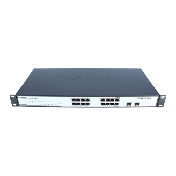
This chapter describes the front panel, rear panel, and LED indicators of the Switch. Front Panel The figure below shows the front panels of the Switch. Figure 4. Front panel of 16-port Gigabit Ethernet Switch. LED Indicator: Comprehensive LED indicators display the status of the Switch and the network (see the LED Indicators chapter below).
-
Page 13: Rear Panel
Rear Panel ● Rese Figure 5. Rear panel of the Switch. AC Power Connector: This is a three-pronged connector that supports the power cord. Plug in the female connector of the provided power cord into this connector, and the male into a power outlet. Supported input voltages range from 100-240V AC at 50-60Hz.
-
Page 14: Understanding Led Indicators
Figure 6. LED indicators of the Switch. Power and System LEDs Power: Power Indicator : When the Power LED lights on, the Switch is receiving power. : When the Power turns off or the power cord is not properly connected. CPU: Management Indicator Blinking : When the CPU is working, the System LED is blinking.
-
Page 15: Option Ports Mini-Gbic 15 & Mini-Gbic 16 Mini-Gbic Status Leds
When the 1000Mbps LED lights on, the respective port is connected to a 1000Mbps Gigabit Ethernet network. When the respective port is connected to a 10Mbps Ethernet or 100Mbps Fast Ethernet network. 100Mbps When the 100Mbps LED lights on, the respective port is connected to a 100Mbps Fast Ethernet network.
-
Page 16: Configuration
CONFIGURATION Through the Web browser you can configure settings on the Switch such as VLAN, Trunking, QoS… etc. With the included Web Management Utility, you can easily discover all the Web Managed switches, assign IP Addresses, change passwords and upgrade new firmware.
-
Page 17: Discovery List
The Web Management Utility is divided into four parts: Discovery List, Monitor List, Device Setting, and Toolbar function. For detailed explanation, follow the section below. Discovery List This is the list where you can discover all the Web management devices in the entire network. By clicking the “Discovery”…
-
Page 18
Gateway: Shows the Gateway set of the device. View Trap: The Trap function can receive the events that occur from the Web Management Switch in the Monitor List. There is a light indicator behind the “View Trap” button. When the indicator lights green, it means that there is no trap transmitted. -
Page 19: Device Setting
Figure 9. Note: In order to receive Trap information, the Switch has to be configured with Trap IP and Trap Events in Web browser, which are available in the Trap Setting Menu (see Page 45 for detail). Add Item: To add a device to the Monitor List manually, enter the IP Address of the device that you want to monitor.
-
Page 20
Figure 10. Configuration Setting Password Change: To change the password, enter the original password, the new password, and confirm the original password. Click the “Set” button to proceed with the password change. Figure 11. Password Change Firmware Upgrade: When the device has a new function, there will be a new firmware to update the device. -
Page 21: Toolbar
Web Access: Double click the device in the Monitor List or select a device in the Monitor List and click the “Web Access” button to access the device in the Web browser. Toolbar The toolbar in the Web Management Utility has four main tabs: File, View, Options, and Help.
-
Page 22: Configuring The Switch
The “Help TAB” has the About function. It will show the current version of the Web Management Utility. Configuring the Switch The DGS-1216T Web Smart Switch has a Web GUI interface for smart switch configuration. The Switch can be configured through the Web Browser. A network administrator can manage, control, and monitor the Switch from the local area network.
-
Page 23
Through the Web Management Utility, you do not need to remember the IP Address. Select the device shown in the Monitor List of the Web Management Utility to settle the device on the Web Browser. When the following dialog page appears, enter the default password «admin»… -
Page 24: Setup Menu
Setup Menu When the main page appears, find the Setup menu in the left side of the screen (Figure 16). Click on the setup item that you want to configure. There are eleven options: Port Settings, VLAN Settings, Trunk Setting, Mirror Setting, Device Status, Statistic, System Settings, Trap Setting, Password Setting, Backup Setting, and Reset Setting, as shown in the Main Menu screen.
-
Page 25
The Link Status in the screen will show the connection speed and duplex mode. If the port is disconnected, the dialog box will display down. Figure 17. Port Setting Note: Be sure that you reset the Gigabit port when transferring the media type (Fiber to Copper or Copper to Fiber). -
Page 26: Vlan Settings (Virtual Local Area Network)
10M Half, Auto, and Disable) for speed or port disable selections. Flow Control: This setting determines whether or not the Switch will be handling flow control. Set FlowCtrl to Enable to avoid data transfer overflows. If set to Disable, there is either no flow control or other hardware/software management.
-
Page 27: Trunk Setting
the “Add Group” button. The new VLAN configuration window will appear. You can fill in the description in order to describe this VLAN Group and check on the port to be a member of this VLAN Group. Click the “Apply” button to execute the setting. Figure 19.
-
Page 28: Mirror Setting
Port Mirroring is a method of monitoring network traffic that forwards a copy of each incoming and/or outgoing packet from one port of a network switch to another port where the packet can be studied. It enables the manager to keep close track of switch performance and alter it if necessary.
-
Page 29: System Setting
Figure 23. Statistic For detailed packet information, click on the ID parameter as shown in Figure 24. Figure 24. System Setting The System Setting includes the System name, Location name, Login Timeout, IP Address, Subnet Mask, and Gateway. Through the Web Management Utility, you can easily recognize the device by using the System Name and the Location Name.
-
Page 30: Trap Setting
Figure 25. Trap Setting The Trap Setting enables the device to monitor the Trap through the Web Management Utility. Set the Trap IP Address of the manager where the trap will be sent. Figure 26. Trap Setting System Events: Monitoring the system’s trap. Device Bootup: A trap when booting up the system.
-
Page 31: Set Password
If you forget the password, press the “Reset” button in the rear panel of the Switch. Current switch settings, such as VLAN, Port Setting… etc. will be lost and the Switch will be restored to the factory default settings. Figure 27. Set Password Backup Setting The backup tools help you to backup the current switch settings.
-
Page 32: Reset Setting
Figure 28. Backup Setting Note: When restoring a recorded file, the current password will not be erased. Reset Setting The Factory Reset button helps you to reset the device back to the factory default settings. Be aware that the entire configuration will be reset.
-
Page 33: Technical Specifications
General Standards IEEE 802.3 10BASE-T Ethernet IEEE 802.3u 100BASE-TX Fast Ethernet IEEE 802.3ab 1000BASE-T Gigabit Ethernet IEEE 802.3x Full Duplex Flow Control IEEE 802.3z 1000BASE-SX/LX Gigabit Ethernet Protocol CSMA/CD Data Transfer Ethernet: 10Mbps (half-duplex), 20Mbps (full-duplex) Rate Fast Ethernet: 100Mbps (half-duplex), 200Mbps (full-duplex) Gigabit Ethernet: 2000Mbps (full-duplex) Topology Star…
-
Page 34
Transmits Method: Store-and-forward Filtering Address 4K entries per device Table: Packet 10Mbps Ethernet: 14,880/pps Filtering/Forwarding 100Mbps Fast Ethernet: 148,800/pps Rate: 1000Mbps Gigabit Ethernet: 1,488,000/pps MAC Address Automatic update Learning: Transmits Method: Store-and-forward RAM Buffer: 272K bytes per device… -
Page 35: Warranty Information
D-Link’s sole obligation shall be to repair or replace the defective Hardware during the Warranty Period at no charge to the original owner or to refund at D-Link’s sole discretion. Such repair or replacement will be rendered by D-Link at an Authorized D-Link Service Office.
-
Page 36
D-Link Systems, 17595 Mt. Herrman Street, Fountain Valley, CA. 92708. D- Link will not be held responsible for any packages that are lost in transit to D-Link. The repaired or replaced packages will be shipped to the customer via UPS Ground or any common carrier selected by D-Link, with shipping charges prepaid. -
Page 37
D-Link; Products that have been purchased from inventory clearance or liquidation sales or other sales in which D-Link, the sellers, or the liquidators expressly disclaim their warranty obligation pertaining to the product. Repair by anyone other than D-Link or an Authorized D-Link Service Office will void this Warranty. -
Page 38
D-Link Corporation/D- Link Systems, Inc., as stipulated by the United States Copyright Act of 1976. Contents are subject to change without prior notice. -
Page 39
Product registration is entirely voluntary and failure to complete or return this form will not diminish your warranty rights.
-
Contents
-
Table of Contents
-
Bookmarks
Quick Links
D-Link DGS-1216T
16-Port 10/100/1000Mbps + 2 Combo Mini
GBIC Gigabit Smart Switch
Manual
Building Networks for People
Related Manuals for D-Link DGS-1216T
Summary of Contents for D-Link DGS-1216T
-
Page 1
D-Link DGS-1216T 16-Port 10/100/1000Mbps + 2 Combo Mini GBIC Gigabit Smart Switch Manual Building Networks for People… -
Page 2: Table Of Contents
Understanding LED Indicators …15 Power and System LEDs …15 Ports 1~16 Status LEDs…15 Option Ports mini-GBIC 15 & mini-GBIC 16 mini-GBIC Status LEDs…16 Configuration…17 Installing the Web Management Utility…17 Discovery List…18 Monitor List…18 Device Setting…20 Toolbar …22 Configuring the Switch…23…
-
Page 3
Setup Menu…25 Configuring Setup Setting …25 Port Settings…25 VLAN Settings (Virtual Local Area Network)…27 Trunk Setting …28 Mirror Setting …29 Device Status …29 Statistic …29 System Setting …30 Trap Setting …31 Set Password…32 Backup Setting…32 Reset Setting …33 Logout…33 Technical Specifications…37… -
Page 4: About This Guide
Ethernet, 100Mbps Fast Ethernet, and 10Mbps Ethernet network capabilities in a highly flexible package. Purpose This manual discusses how to install and configure the DGS-1216T Web Smart Switch. Terms/Usage In this manual, the term “Switch” (first letter upper case) refers to your DGS- 1216T Web Smart Switch, and “switch”…
-
Page 5: Introduction
INTRODUCTION This chapter describes the features of the DGS-1216T and some background information about Ethernet/Fast Ethernet/Gigabit Ethernet switching technology. Gigabit Ethernet Technology Gigabit Ethernet is an extension of IEEE 802.3 Ethernet utilizing the same packet structure, format, and support for CSMA/CD protocol, full-duplex, flow…
-
Page 6: Fast Ethernet Technology
Ethernet or Fast Ethernet LAN segments. Switching is a cost-effective way of increasing the total network capacity available to users on a local area network. A switch increases capacity and decreases network loading by dividing a local area network into different segments, which do not compete with each other for network transmission capacity.
-
Page 7: Vlan (Virtual Local Area Network)
Cost Reduction: VLANs can be used to create multiple broadcast domains, thus eliminating the need of expensive routers. Port-based (or port-group) VLAN is the common method of implementing a VLAN, and is the one supplied in the Switch. Features 16×10/100/1000Mbps Auto-negotiation Gigabit Ethernet ports…
-
Page 8
Supports port-base QoS Supports Port-trunking Supports Port-mirroring Supports Port-setting for Speed/Disable, Flow control Easy configuration via Web Browser Easy setting via Web Management Utility Standard 19” Rack-mount size… -
Page 9: Unpacking And Installation
This chapter provides unpacking and installation information for the Switch. Unpacking Open the shipping carton of the Switch and carefully unpacks its contents. The carton should contain the following items: One DGS-1216T Web Smart Switch One AC power cord, suitable for your area’s electrical power…
-
Page 10: Rack Mounting
Figure 1. Attach the adhesive rubber pads to the bottom. Rack Mounting The Switch can be mounted in an EIA standard-size, 19-inch rack, which can be placed in a wiring closet with other equipment. Attach the mounting brackets at the Switch’s front panel (one on each side), and secure them with the provided screws.
-
Page 11: Connecting Network Cable
AC Power The Switch uses a 100-240V AC, 50-60 Hz AC power supply. The power switch is located at the rear of the unit adjacent to the AC power connector and the system fan. The Switch’s power supply will adjust to the local power source automatically and may be turned on without having any or all LAN segment cables connected.
-
Page 12: Identifying External Components
This chapter describes the front panel, rear panel, and LED indicators of the Switch. Front Panel The figure below shows the front panels of the Switch. Figure 4. Front panel of 16-port Gigabit Ethernet Switch. LED Indicator: Comprehensive LED indicators display the status of the Switch and the network (see the LED Indicators chapter below).
-
Page 13: Rear Panel
Rear Panel ● Rese Figure 5. Rear panel of the Switch. AC Power Connector: This is a three-pronged connector that supports the power cord. Plug in the female connector of the provided power cord into this connector, and the male into a power outlet. Supported input voltages range from 100-240V AC at 50-60Hz.
-
Page 14: Understanding Led Indicators
Figure 6. LED indicators of the Switch. Power and System LEDs Power: Power Indicator : When the Power LED lights on, the Switch is receiving power. : When the Power turns off or the power cord is not properly connected. CPU: Management Indicator Blinking : When the CPU is working, the System LED is blinking.
-
Page 15: Option Ports Mini-Gbic 15 & Mini-Gbic 16 Mini-Gbic Status Leds
When the 1000Mbps LED lights on, the respective port is connected to a 1000Mbps Gigabit Ethernet network. When the respective port is connected to a 10Mbps Ethernet or 100Mbps Fast Ethernet network. 100Mbps When the 100Mbps LED lights on, the respective port is connected to a 100Mbps Fast Ethernet network.
-
Page 16: Configuration
CONFIGURATION Through the Web browser you can configure settings on the Switch such as VLAN, Trunking, QoS… etc. With the included Web Management Utility, you can easily discover all the Web Managed switches, assign IP Addresses, change passwords and upgrade new firmware.
-
Page 17: Discovery List
The Web Management Utility is divided into four parts: Discovery List, Monitor List, Device Setting, and Toolbar function. For detailed explanation, follow the section below. Discovery List This is the list where you can discover all the Web management devices in the entire network. By clicking the “Discovery”…
-
Page 18
Gateway: Shows the Gateway set of the device. View Trap: The Trap function can receive the events that occur from the Web Management Switch in the Monitor List. There is a light indicator behind the “View Trap” button. When the indicator lights green, it means that there is no trap transmitted. -
Page 19: Device Setting
Figure 9. Note: In order to receive Trap information, the Switch has to be configured with Trap IP and Trap Events in Web browser, which are available in the Trap Setting Menu (see Page 45 for detail). Add Item: To add a device to the Monitor List manually, enter the IP Address of the device that you want to monitor.
-
Page 20
Figure 10. Configuration Setting Password Change: To change the password, enter the original password, the new password, and confirm the original password. Click the “Set” button to proceed with the password change. Figure 11. Password Change Firmware Upgrade: When the device has a new function, there will be a new firmware to update the device. -
Page 21: Toolbar
Web Access: Double click the device in the Monitor List or select a device in the Monitor List and click the “Web Access” button to access the device in the Web browser. Toolbar The toolbar in the Web Management Utility has four main tabs: File, View, Options, and Help.
-
Page 22: Configuring The Switch
The “Help TAB” has the About function. It will show the current version of the Web Management Utility. Configuring the Switch The DGS-1216T Web Smart Switch has a Web GUI interface for smart switch configuration. The Switch can be configured through the Web Browser. A network administrator can manage, control, and monitor the Switch from the local area network.
-
Page 23
Through the Web Management Utility, you do not need to remember the IP Address. Select the device shown in the Monitor List of the Web Management Utility to settle the device on the Web Browser. When the following dialog page appears, enter the default password «admin»… -
Page 24: Setup Menu
Setup Menu When the main page appears, find the Setup menu in the left side of the screen (Figure 16). Click on the setup item that you want to configure. There are eleven options: Port Settings, VLAN Settings, Trunk Setting, Mirror Setting, Device Status, Statistic, System Settings, Trap Setting, Password Setting, Backup Setting, and Reset Setting, as shown in the Main Menu screen.
-
Page 25
The Link Status in the screen will show the connection speed and duplex mode. If the port is disconnected, the dialog box will display down. Figure 17. Port Setting Note: Be sure that you reset the Gigabit port when transferring the media type (Fiber to Copper or Copper to Fiber). -
Page 26: Vlan Settings (Virtual Local Area Network)
10M Half, Auto, and Disable) for speed or port disable selections. Flow Control: This setting determines whether or not the Switch will be handling flow control. Set FlowCtrl to Enable to avoid data transfer overflows. If set to Disable, there is either no flow control or other hardware/software management.
-
Page 27: Trunk Setting
the “Add Group” button. The new VLAN configuration window will appear. You can fill in the description in order to describe this VLAN Group and check on the port to be a member of this VLAN Group. Click the “Apply” button to execute the setting. Figure 19.
-
Page 28: Mirror Setting
Port Mirroring is a method of monitoring network traffic that forwards a copy of each incoming and/or outgoing packet from one port of a network switch to another port where the packet can be studied. It enables the manager to keep close track of switch performance and alter it if necessary.
-
Page 29: System Setting
Figure 23. Statistic For detailed packet information, click on the ID parameter as shown in Figure 24. Figure 24. System Setting The System Setting includes the System name, Location name, Login Timeout, IP Address, Subnet Mask, and Gateway. Through the Web Management Utility, you can easily recognize the device by using the System Name and the Location Name.
-
Page 30: Trap Setting
Figure 25. Trap Setting The Trap Setting enables the device to monitor the Trap through the Web Management Utility. Set the Trap IP Address of the manager where the trap will be sent. Figure 26. Trap Setting System Events: Monitoring the system’s trap. Device Bootup: A trap when booting up the system.
-
Page 31: Set Password
If you forget the password, press the “Reset” button in the rear panel of the Switch. Current switch settings, such as VLAN, Port Setting… etc. will be lost and the Switch will be restored to the factory default settings. Figure 27. Set Password Backup Setting The backup tools help you to backup the current switch settings.
-
Page 32: Reset Setting
Figure 28. Backup Setting Note: When restoring a recorded file, the current password will not be erased. Reset Setting The Factory Reset button helps you to reset the device back to the factory default settings. Be aware that the entire configuration will be reset.
-
Page 33: Technical Specifications
General Standards IEEE 802.3 10BASE-T Ethernet IEEE 802.3u 100BASE-TX Fast Ethernet IEEE 802.3ab 1000BASE-T Gigabit Ethernet IEEE 802.3x Full Duplex Flow Control IEEE 802.3z 1000BASE-SX/LX Gigabit Ethernet Protocol CSMA/CD Data Transfer Ethernet: 10Mbps (half-duplex), 20Mbps (full-duplex) Rate Fast Ethernet: 100Mbps (half-duplex), 200Mbps (full-duplex) Gigabit Ethernet: 2000Mbps (full-duplex) Topology Star…
-
Page 34
Transmits Method: Store-and-forward Filtering Address 4K entries per device Table: Packet 10Mbps Ethernet: 14,880/pps Filtering/Forwarding 100Mbps Fast Ethernet: 148,800/pps Rate: 1000Mbps Gigabit Ethernet: 1,488,000/pps MAC Address Automatic update Learning: Transmits Method: Store-and-forward RAM Buffer: 272K bytes per device… -
Page 35: Warranty Information
D-Link’s sole obligation shall be to repair or replace the defective Hardware during the Warranty Period at no charge to the original owner or to refund at D-Link’s sole discretion. Such repair or replacement will be rendered by D-Link at an Authorized D-Link Service Office.
-
Page 36
D-Link Systems, 17595 Mt. Herrman Street, Fountain Valley, CA. 92708. D- Link will not be held responsible for any packages that are lost in transit to D-Link. The repaired or replaced packages will be shipped to the customer via UPS Ground or any common carrier selected by D-Link, with shipping charges prepaid. -
Page 37
D-Link; Products that have been purchased from inventory clearance or liquidation sales or other sales in which D-Link, the sellers, or the liquidators expressly disclaim their warranty obligation pertaining to the product. Repair by anyone other than D-Link or an Authorized D-Link Service Office will void this Warranty. -
Page 38
D-Link Corporation/D- Link Systems, Inc., as stipulated by the United States Copyright Act of 1976. Contents are subject to change without prior notice. -
Page 39
Product registration is entirely voluntary and failure to complete or return this form will not diminish your warranty rights.
Краткое содержание страницы № 1
D-Link DGS-1216T
16-Port 10/100/1000Mbps
Gigabit Ethernet Switch + 2-Port mini GBIC
Web-Smart Switch
Manual
Second Edition
Building Networks for People
Краткое содержание страницы № 2
Краткое содержание страницы № 3
TABLE OF CONTENT About This Guide……………………………………………………………………… 1 Purpose ……………………………………………………………………………….. 1 Terms/Usage ………………………………………………………………………… 1 Introduction……………………………………………………………………………… 3 Gigabit Ethernet Technology……………………………………..
Краткое содержание страницы № 4
Installing the Web Management Utility………………………………….. 18 Discovery List…………………………………………………………………….. 19 Monitor List ……………………………………………………………………….. 20 Device Setting…………………………………………………………………….. 22 Toolbar………………………………………………………………………………. 23 Configuring the
Краткое содержание страницы № 5
Technical Specifications ………………………………………………………….. 48 iii
Краткое содержание страницы № 6
Краткое содержание страницы № 7
ABOUT THIS GUIDE Congratulations on your purchase of the DGS-1216T 16-Port 10/100/1000Mbps Gigabit Ethernet+2-Port Mini GBIC Web Smart Switch. This device integrates 1000Mbps Gigabit Ethernet, 100Mbps Fast Ethernet and 10Mbps Ethernet network capabilities in a highly flexible package. Purpose This guide discusses how to install and configure the DGS-1216T Web Smart Switch. Terms/Usage In this guide, the term “Switch” (first letter upper case) refers to your DGS-1216T Web Smart Switch
Краткое содержание страницы № 8
Краткое содержание страницы № 9
INTRODUCTION This chapter describes the features of the DGS-1216T and some background information about Ethernet/Fast Ethernet/Gigabit Ethernet switching technology. Gigabit Ethernet Technology Gigabit Ethernet is an extension of IEEE 802.3 Ethernet utilizing the same packet structure, format, and support for CSMA/CD protocol, full duplex, flow control, and management objects, but with a tenfold increase in theoretical throughput over 100-Mbps Fast Ethernet and a hundredfold increase ov
Краткое содержание страницы № 10
tomorrow’s rapidly improving switching and routing internetworking technologies. And with expected advances in the coming years in silicon technology and digital signal processing that will enable Gigabit Ethernet to eventually operate over unshielded twisted-pair (UTP) cabling, outfitting your network with a powerful 1000-Mbps- capable backbone/server connection creates a flexible foundation for the next generation of network technology products. Fast Ethernet Technology The growing impo
Краткое содержание страницы № 11
Switching Technology Another approach to pushing beyond the limits of Ethernet technology is the development of switching technology. A switch bridges Ethernet packets at the MAC address level of the Ethernet protocol transmitting among connected Ethernet or Fast Ethernet LAN segments. Switching is a cost-effective way of increasing the total network capacity available to users on a local area network. A switch increases capacity and decreases network loading by dividing a local area n
Краткое содержание страницы № 12
VLAN (Virtual Local Area Network) A VLAN is a group of end-stations that are not constrained by their physical location and can communicate as if a common broadcast domain, a LAN. The primary utility of using VLAN is to reduce latency and need for routers, using faster switching instead. Other VLAN utility includes: Security, Security is increased with the reduction of opportunity in eavesdropping on a broadcast network because data will be switched to only those confidential users withi
Краткое содержание страницы № 13
Up to 8K unicast addresses entities per device, self-learning, and table aging 512KBytes packet buffer Supports IEEE 802.3x flow control for full-duplex mode ports Supports IEEE 802.1Q-based VLAN Supports IEEE 802.1P-based QoS Supports Port-trunking Supports Port-mirroring Supports Port-setting for Speed/Disable, Flow control and Port Priority Support Jumbo-frame setting Supports IEEE 802.1D Spanning Tree protocol Support Simple Network Management Protocol (SNMP) Suppor
Краткое содержание страницы № 14
Краткое содержание страницы № 15
UNPACKING AND INSTALLATION This chapter provides unpacking and installation information for the Switch. Unpacking Open the shipping cartons of the Switch and carefully unpacks its contents. The carton should contain the following items: One DGS-1216T Web Smart Switch One AC power cord, suitable for your area’s electrical power connections Four rubber feet to be used for shock cushioning Screws and two mounting brackets CD-Rom with Web Management Utility and User’s Guide Quick
Краткое содержание страницы № 16
Leave at least 10cm of space at the front and rear of the hub for ventilation. Install the Switch on a sturdy, level surface that can support its weight, or in an EIA standard-size equipment rack. For information on rack installation, see the next section, Rack Mounting. When installing the Switch on a level surface, attach the rubber feet to the bottom of each device. The rubber feet cushion the hub and protect the hub case from scratching. Figure 1. Attach the adhesive rubber pads
Краткое содержание страницы № 17
Then, use screws provided with the equipment rack to mount each switch in the rack. Figure 3. Mount the Switch in the rack Connecting Network Cable The Switch supports 1000Mbps Gigabit Ethernet that runs in Auto- negotiation mode and 10Mbps Ethernet or 100Mbps Fast Ethernet that runs both in half and full duplex mode and 1000Mbps Gigabit Ethernet runs in full duplex mode using four pair of Category 5 Cable. These RJ-45 ports are Auto-MDI type port. The Switch can auto transform to MDI-
Краткое содержание страницы № 18
Краткое содержание страницы № 19
IDENTIFYING EXTERNAL COMPONENTS This chapter describes the front panel, rear panel, and LED indicators of the Switch. Front Panel The figure below shows the front panels of the Switch. Figure 4. Front panel of 16-port Gigabit Ethernet Switch LED Indicator: Comprehensive LED indicators display the status of the switch and the network (see the LED Indicators chapter below). Gigabit Ethernet Ports (Port 1~16): The Switch sixteen Gigabit twisted pair ports, supported auto negotiable 10
Краткое содержание страницы № 20
Rear Panel ● Reset button Figure 5. Rear panel of the Switch AC Power Connector: This is a three-pronged connector that supports the power cord. Plug in the female connector of the provided power cord into this connector, and the male into a power outlet. Supported input voltages range from 100-240V AC at 50-60Hz. Reset: The Reset button is to reset all the setting back to the factory default. Note: Be sure that you recorded the setting of your device, else all the setting will be
Введение
Данное руководство содержит пошаговые инструкции
для настройки всех коммутаторов серии D-Link Web
Smart.
Пожалуйста,
приобретенная
модель
отличаться от изображенной на иллюстрациях. За
более подробной информацией о коммутаторе, его
компонентах, подключении к сети и технической
спецификацией,
пожалуйста,
руководству пользователя, включенного в комплект
поставки коммутатора.
Шаг 1 – Распаковка
Откройте
коробку
содержимое. Пожалуйста, сверьтесь со списком
комплекта поставки, расположенным в руководстве
пользователя. Если какой-то из этих элементов
отсутствует или поврежден, пожалуйста, обратитесь
к продавцу для замены.
— Один коммутатор D-Link Web Smart
— Кронштейны для монтажа в стойку
— Шнур питания
— Компакт-диск с руководством пользователя и
утилитой SmartConsole
— Одно мультиязычное руководство по быстрой
установке
Шаг 2 – Установка
коммутатора
Для безопасной работы и установки коммутатора
необходимо сделать следующие шаги:
♦ Визуально
проверьте
убедитесь в безопасности его подключения к
разъему питания переменного тока
♦ Убедитесь, что вокруг коммутатора достаточно
пространства для вентиляции
♦ Не размещайте тяжелые или нагревающиеся
объекты на коммутаторе
Установка на стол или поверхность
При установке коммутатора на стол или какую-нибудь
поверхность,
необходимо
поставляемые вместе с ним резиновые ножки.
Самоклеющиеся ножки крепятся на дне устройства
по его углам. Обеспечьте достаточное пространство
для вентиляции между устройством и объектами
вокруг него.
имейте
в
виду,
может
незначительно
обратитесь
и
аккуратно
достаньте
силовой
кабель
прикрепить
что
к
Установка в стойку
Коммутатор допускает установку в 19-дюймовую
стойку EIA , которая, как правило, размещается в
ее
серверной комнате вместе с другим оборудованием.
Прикрепите монтажные уголки к боковым панелям
коммутатора (по одному с каждой стороны) и
закрепите их прилагаемыми винтами.
Рисунок 2. Крепление монтажных уголков
Затем, используя винты от стойки, закрепите на ней
коммутатор.
и
Рисунок 3. Установка коммутатора в стандартную
Шаг 3 – Подключение кабеля
питания переменного тока
На данном шаге подключите кабель питания к
к
нему
розетке сети питания (желательно заземленной и
защищенной от перепадов напряжения).
22
Рисунок 1. Крепление резиновых ножек
стойку

DGS-1216T
Настраиваемый коммутатор
D-Link 16-портов 10/100/1000Mбит/с + 2 Combo Mini GBIC Gigabit
Broadband Router

Прежде, чем начать
В этом руководстве по быстрой установке описана последовательность шагов для установки настраиваемого коммутатора Gigabit Ethernet D-Link DGS-1216T Модель, которую Вы купили, может незначительно отличаться от показанной на иллюстрациях. За более подробной информацией о коммутаторе, его компонентах, подключении к сети и технической спецификации, обратитесь, пожалуйста, к руководству пользователя на компакт-диске, включенном в комплект поставки коммутатора.
Проверьте содержимое комплекта поставки
Эти элементы входят в комплект поставки DGS-1216T:
D-Link 16-портов 10/100/1000Mбит/с + 2 Combo Mini GBIC Gigabit
• CD-ROM (содержит руководство пользователя и утилиту установки)
• 100–240В 50/60Гц
Адаптер питания

![]()


![]()
Если что-либо из перечисленного отсутствует, обратитесь к вашему поставщику.
©2003 D-Link Systems, Inc. All rights reserved. Trademarks or registered trademarks are the property of their respective holders. Software and specifications subject to change without notice.
У становка коммутатора Gigabit Ethernet DGS-1216T
 становка коммутатора Gigabit Ethernet DGS-1216T
 Установка коммутаторы может быть выполнена следующим образом:
- Установите DGS-1216T в достаточно прохладное и сухое место. См. Техническую спецификацию для выбора приемлемого диапазона рабочей температуры и влажности.
- Установите DGS-1216T на место, защищенное от генераторов сильного электромагнитного поля (например двигателей), вибрации, пыли и попадания прямых солнечных лучей.
- Оставьте как минимум 10 см свободного пространства спереди и сзади коммутатора для вентиляции.
- Визуально проверьте гнездо питания постоянного тока и убедитесь, что адаптер питания полностью прилегает к нему.
- Установите DGS-1216T ровную, устойчивую поверхность, которая может выдержать его вес или в телекоммуникационную стойку стандартного размера.
- При установке коммутатора на ровную поверхность, присоедините резиновые «ножки» к нижней части каждого устройства. Резиновые «ножки» являются прокладкой и защищают корпус коммутатора от царапин.

Прикрепите клеящиеся резиновые прокладки к нижней стороне корпуса

Установка в стойку
DGS-1216T может быть вмонтирован в 19-ти дюймовую стойку стандартного EIA размера, которая может находиться в аппаратной, вместе с другим оборудованием. Присоедините крепежные скобы к обеим сторонам коммутатора (по одной к каждой стороне) и закрепите их включенными в поставку шурупами.

Используйте шурупы из комплекта поставки. Затем, шурупами, поставляемыми со стойкой, прикрепите коммутатор к стойке.

Монтаж коммутатора в стойку
Подключение сетевого кабеля
DGS-1216T поддерживает 10/100/1000Mбит/с Gigabit Ethernet. Он работает в режимах полного /полу дуплекса для 10/100Mбит/с и полного дуплекса 1000Mбит/с. Каждый порт DGS-1216T поддерживает автоматическое определение полярности Auto-MDI/MDI-X. Auto-MDI/MDI-X – это функция, которая позволяет использовать для подключения любой тип кабеля (прямой или кроссовый) и любому порту быть uplink портом.
Питание
DGS-1216T может использоваться с источником питания переменного тока 100~240В, 50~60Гц. Выключатель питания находится на задней панели устройства рядом с разъемом питания и системным вентилятором. Блок питания коммутатора соединится с локальным источником энергии автоматически и может быть включён без подключения каких-либо сегментов сети.
 Подключение настраиваемого гигабитного коммутатора
DGS-1216T к сети
Передняя панель
10/100/1000 Base-T Mini GBIC порты
порты на витой паре
┌──────────┐ ┌──┐
![]()
└─────┘
Индикаторы
- 1000BASE-T порты на витой паре (Порт 1~16)
DGS-1216T оборудован 16-ю гигабитными портами на витой паре, поддерживающими автосогласование 10/100/1000Mбит/с и автоматическое определение полярности MDI/MDIX. Эти порты могут работать в полу и полнодуплексном режимах работы.
- Mini GBIC порты (Дополнительные порты 15~16)
Коммутатор оборудован двумя mini-GBIC портами, поддерживающими дополнительные модули 1000BASE-SX/LX Mini GBIC.
Примечание: Когда порт устанавливается в режим “Forced Mode”(принудительный режим), автоматическое определение полярности Auto MDI/MDIX будет отключено.
И ндикаторы
 ндикаторы
LED означает Light-Emitting Diode (Свето — испускающий диод).
Индикаторы на передней панели позволяет мгновенно получить информацию о состоянии и упрощают задачи мониторинга и поиска неисправностей..

Индикаторы коммутатора
- Индикаторы Power (Питание)
On Когда индикатор Питание горит, коммутатор получает питание. Off Когда индикатор Питание не горит, неправильно подключен шнур питания. - Индикаторы CPU ( Индикаторы управления)
-
Мигает Когда CPU работает, индикатор System мигает. On/Off CPU не работает.
- Индикаторы состояния портов 1 — 16
Link/Act
| On | Когда индикатор Link/Act горит, соответствующий порт успешно подключен к сети Ethernet. | |
| Мигает | Когда индикатор Link/Act мигает, порт передает или получает данные из сети Ethernet. | |
| Off | Нет связи. |
1000Mbps
| On | Когда индикатор 1000Mbps горит, соответствующий порт подключен к сети 1000Mбит/с Gigabit Ethernet. | |
| Off | Когда индикатор не горит, соответствующий порт подключен к сети 10Мбит/с Ethernet или 100Mбит/с Fast Ethernet. |
100Mbps
| On | Когда индикатор горит, соответствующий порт подключен к сети 100Mбит/с Fast Ethernet.. | |
| Off | Когда индикатор не горит, соответствующий порт подключен к сети 10Мбит/с или сети 1000Мбит/с Gigabit Ethernet. |
- Индикаторы состояния дополнительных портов Mini-GBIC 15~16
Link/Act
-
On Когда модуль mini-GBIC установлен и подключен к сети, индикатор Link/ACT горит. Мигает Когда индикатор мигает, модуль mini-GBIC получает данные из сети. Off Нет связи.
1000Mbps
-
On Когда индикатор 1000Mbps горит, соответствующий порт подключен к сети 1000Mбит/с Gigabit Ethernet Off Когда соответствующий порт отключен от сети
 Установка утилиты Web — управления
Используя Web браузер можно настроить такие функции коммутатора, как VLAN, агрегирование портов, QoS… и т.д..
Следующие инструкции помогут установить утилиту Web-управления.
- Вставить диск с утилитой в привод CD-Rom.
- Из меню Пуск на рабочем столе Windows выбрать Выполнить.
- В диалоговом окне Выполнить, набрать D:Web Management Utilitysetup.exe (D: означает букву Вашего привода СD-Rom) и нажать OK.
- Следуйте экранным командам, чтобы установить утилиту.
- После завершения, перейдите к Program Files -> web_management_utility и запустите утилиту Web-управления. (Рисунок 1.)

Рисунок 1. Утилита Web-управления

Настройка коммутатора
DGS-1216T имеет графический Web-интерфейс для настройки конфигурации коммутатора. Коммутатор может быть настроен с помощью Web браузера. Сетевой администратор может настраивать, управлять и контролировать коммутатор из локальной сети. В этом разделе описывается, как настроить коммутатор, для получения доступа к его «интеллектуальным» функциям.
Используйте Web браузер Internet Explorer 5.0 или выше.
Регистрация
Перед тем, как начать конфигурировать устройство, напомним, что настраиваемый по Web коммутатор, конфигурируется через Ethernet соединение, поэтому убедитесь, что управляющий ПК находится в той же самой IP сети. Например, если по умолчанию IP адрес коммутатора равен 192.168.0.1, то адрес сети управляющего компьютера должен быть установлен в 192.168.0.x (где х означает номер между 2 и 254), и маска подсети по умолчанию должна быть равна 255.255.255.0.
Введите IP адрес
http://192.168.0.1 (установленное по умолчанию значение IP адреса) в адресной строке. (Рисунок 2).
![]()
Рисунок 2.
При использовании утилиты Web-управления, нет необходимости запоминать IP адрес, просто выберите устройство, которое показано в списке Monitor List утилиты Web-управления для установки параметров устройства в браузере.
Когда появится следующее диалоговое окно, не забудьте ввести пароль «admin« и нажать Login для получения доступа к главному окну настройки. (Рисунок 3.)

Рисунок 3.
После ввода пароля, появится главная страница, экран отобразит состояние устройства. (Рисунок 4.)

Рисунок 4.
Меню установки
Когда появится главная страница, на левой стороне экрана найдите Setup menu. (Рисунок 5.) Нажмите на пункте меню, который вы хотите конфигурировать. Доступно 11 пунктов меню: Port Settings, VLAN Settings, Trunk Setting, Mirror Setting, Device Status, Statistic, System Settings, Trap Setting, Password Setting, Backup Setting and Reset Setting, как показано на экране главного меню.

Рисунок 5.
-
D-Link DGS-1216T — page 1
…
-
D-Link DGS-1216T — page 2
…
-
D-Link DGS-1216T — page 3
…
-
D-Link DGS-1216T — page 4
…
-
D-Link DGS-1216T — page 5
…
-
D-Link DGS-1216T — page 6
…
-
D-Link DGS-1216T — page 7
…
-
D-Link DGS-1216T — page 8
…
-
D-Link DGS-1216T — page 9
…
-
D-Link DGS-1216T — page 10
…
-
D-Link DGS-1216T — page 11
…
-
D-Link DGS-1216T — page 12
…
-
D-Link DGS-1216T — page 13
…
-
D-Link DGS-1216T — page 14
…
-
D-Link DGS-1216T — page 15
…
-
D-Link DGS-1216T — page 16
…
-
D-Link DGS-1216T — page 17
…
-
D-Link DGS-1216T — page 18
…
-
D-Link DGS-1216T — page 19
…
-
D-Link DGS-1216T — page 20
…
-
D-Link DGS-1216T — page 21
…
-
D-Link DGS-1216T — page 22
…
-
D-Link DGS-1216T — page 23
…
-
D-Link DGS-1216T — page 24
…
-
D-Link DGS-1216T — page 25
…
-
D-Link DGS-1216T — page 26
…
-
D-Link DGS-1216T — page 27
…
-
D-Link DGS-1216T — page 28
…
-
D-Link DGS-1216T — page 29
…
-
D-Link DGS-1216T — page 30
…
-
D-Link DGS-1216T — page 31
…
-
D-Link DGS-1216T — page 32
…
-
D-Link DGS-1216T — page 33
…
-
D-Link DGS-1216T — page 34
…
-
D-Link DGS-1216T — page 35
…
-
D-Link DGS-1216T — page 36
…
-
D-Link DGS-1216T — page 37
…
-
D-Link DGS-1216T — page 38
…
-
D-Link DGS-1216T — page 39
…
-
D-Link DGS-1216T — page 40
…
-
D-Link DGS-1216T — page 41
…
-
D-Link DGS-1216T — page 42
…
-
D-Link DGS-1216T — page 43
…
-
D-Link DGS-1216T — page 44
…
-
D-Link DGS-1216T — page 45
…
-
D-Link DGS-1216T — page 46
…
-
D-Link DGS-1216T — page 47
…
-
D-Link DGS-1216T — page 48
…
-
D-Link DGS-1216T — page 49
…
-
D-Link DGS-1216T — page 50
…
-
D-Link DGS-1216T — page 51
…
-
D-Link DGS-1216T — page 52
…
-
D-Link DGS-1216T — page 53
…
-
D-Link DGS-1216T — page 54
…
-
D-Link DGS-1216T — page 55
…
-
D-Link DGS-1216T — page 56
…
-
D-Link DGS-1216T — page 57
…
-
D-Link DGS-1216T — page 58
…
-
D-Link DGS-1216T — page 59
…
-
D-Link DGS-1216T — page 60
…
-
D-Link DGS-1216T — page 61
…
Краткое содержание страницы № 1
D-Link DGS-1216T
16-Port 10/100/1000Mbps
Gigabit Ethernet Switch + 2-Port mini GBIC
Web-Smart Switch
Manual
Second Edition
Building Networks for People
Краткое содержание страницы № 2
Краткое содержание страницы № 3
TABLE OF CONTENT About This Guide……………………………………………………………………… 1 Purpose ……………………………………………………………………………….. 1 Terms/Usage ………………………………………………………………………… 1 Introduction……………………………………………………………………………… 3 Gigabit Ethernet Technology……………………………………..
Краткое содержание страницы № 4
Installing the Web Management Utility………………………………….. 18 Discovery List…………………………………………………………………….. 19 Monitor List ……………………………………………………………………….. 20 Device Setting…………………………………………………………………….. 22 Toolbar………………………………………………………………………………. 23 Configuring the
Краткое содержание страницы № 5
Technical Specifications ………………………………………………………….. 48 iii
Краткое содержание страницы № 6
Краткое содержание страницы № 7
ABOUT THIS GUIDE Congratulations on your purchase of the DGS-1216T 16-Port 10/100/1000Mbps Gigabit Ethernet+2-Port Mini GBIC Web Smart Switch. This device integrates 1000Mbps Gigabit Ethernet, 100Mbps Fast Ethernet and 10Mbps Ethernet network capabilities in a highly flexible package. Purpose This guide discusses how to install and configure the DGS-1216T Web Smart Switch. Terms/Usage In this guide, the term “Switch” (first letter upper case) refers to your DGS-1216T Web Smart Switch
Краткое содержание страницы № 8
Краткое содержание страницы № 9
INTRODUCTION This chapter describes the features of the DGS-1216T and some background information about Ethernet/Fast Ethernet/Gigabit Ethernet switching technology. Gigabit Ethernet Technology Gigabit Ethernet is an extension of IEEE 802.3 Ethernet utilizing the same packet structure, format, and support for CSMA/CD protocol, full duplex, flow control, and management objects, but with a tenfold increase in theoretical throughput over 100-Mbps Fast Ethernet and a hundredfold increase ov
Краткое содержание страницы № 10
tomorrow’s rapidly improving switching and routing internetworking technologies. And with expected advances in the coming years in silicon technology and digital signal processing that will enable Gigabit Ethernet to eventually operate over unshielded twisted-pair (UTP) cabling, outfitting your network with a powerful 1000-Mbps- capable backbone/server connection creates a flexible foundation for the next generation of network technology products. Fast Ethernet Technology The growing impo
Краткое содержание страницы № 11
Switching Technology Another approach to pushing beyond the limits of Ethernet technology is the development of switching technology. A switch bridges Ethernet packets at the MAC address level of the Ethernet protocol transmitting among connected Ethernet or Fast Ethernet LAN segments. Switching is a cost-effective way of increasing the total network capacity available to users on a local area network. A switch increases capacity and decreases network loading by dividing a local area n
Краткое содержание страницы № 12
VLAN (Virtual Local Area Network) A VLAN is a group of end-stations that are not constrained by their physical location and can communicate as if a common broadcast domain, a LAN. The primary utility of using VLAN is to reduce latency and need for routers, using faster switching instead. Other VLAN utility includes: Security, Security is increased with the reduction of opportunity in eavesdropping on a broadcast network because data will be switched to only those confidential users withi
Краткое содержание страницы № 13
Up to 8K unicast addresses entities per device, self-learning, and table aging 512KBytes packet buffer Supports IEEE 802.3x flow control for full-duplex mode ports Supports IEEE 802.1Q-based VLAN Supports IEEE 802.1P-based QoS Supports Port-trunking Supports Port-mirroring Supports Port-setting for Speed/Disable, Flow control and Port Priority Support Jumbo-frame setting Supports IEEE 802.1D Spanning Tree protocol Support Simple Network Management Protocol (SNMP) Suppor
Краткое содержание страницы № 14
Краткое содержание страницы № 15
UNPACKING AND INSTALLATION This chapter provides unpacking and installation information for the Switch. Unpacking Open the shipping cartons of the Switch and carefully unpacks its contents. The carton should contain the following items: One DGS-1216T Web Smart Switch One AC power cord, suitable for your area’s electrical power connections Four rubber feet to be used for shock cushioning Screws and two mounting brackets CD-Rom with Web Management Utility and User’s Guide Quick
Краткое содержание страницы № 16
Leave at least 10cm of space at the front and rear of the hub for ventilation. Install the Switch on a sturdy, level surface that can support its weight, or in an EIA standard-size equipment rack. For information on rack installation, see the next section, Rack Mounting. When installing the Switch on a level surface, attach the rubber feet to the bottom of each device. The rubber feet cushion the hub and protect the hub case from scratching. Figure 1. Attach the adhesive rubber pads
Краткое содержание страницы № 17
Then, use screws provided with the equipment rack to mount each switch in the rack. Figure 3. Mount the Switch in the rack Connecting Network Cable The Switch supports 1000Mbps Gigabit Ethernet that runs in Auto- negotiation mode and 10Mbps Ethernet or 100Mbps Fast Ethernet that runs both in half and full duplex mode and 1000Mbps Gigabit Ethernet runs in full duplex mode using four pair of Category 5 Cable. These RJ-45 ports are Auto-MDI type port. The Switch can auto transform to MDI-
Краткое содержание страницы № 18
Краткое содержание страницы № 19
IDENTIFYING EXTERNAL COMPONENTS This chapter describes the front panel, rear panel, and LED indicators of the Switch. Front Panel The figure below shows the front panels of the Switch. Figure 4. Front panel of 16-port Gigabit Ethernet Switch LED Indicator: Comprehensive LED indicators display the status of the switch and the network (see the LED Indicators chapter below). Gigabit Ethernet Ports (Port 1~16): The Switch sixteen Gigabit twisted pair ports, supported auto negotiable 10
Краткое содержание страницы № 20
Rear Panel ● Reset button Figure 5. Rear panel of the Switch AC Power Connector: This is a three-pronged connector that supports the power cord. Plug in the female connector of the provided power cord into this connector, and the male into a power outlet. Supported input voltages range from 100-240V AC at 50-60Hz. Reset: The Reset button is to reset all the setting back to the factory default. Note: Be sure that you recorded the setting of your device, else all the setting will be

![]() Руководство по эксплуатации интернет коммутатор D-Link DGS-1216T 16-Port
Руководство по эксплуатации интернет коммутатор D-Link DGS-1216T 16-Port
скачать мануал на русском языке 16-ти портовый интернет коммутатор D-Link DGS-1216T
Инструкция по эксплуатации для пользователя интернет коммутатор D-Link DGS-1216T 16-Port содержит информацию о распаковке и установке. Распаковка устройства не сложная, но требует определенной сноровки и знаний, которые можно получить из справочника для пользователя, прилагаемого в комплекте. Откройте упаковочные коробки коммутатора и аккуратно распакуйте его.
При установке учитывайте следующие указатели: Установите коммутатор в достаточно прохладном и сухом месте. Смотрите технический спецификации для приемлемой температуры и влажности эксплуатации диапазоны. Установите коммутатор в месте, свободном от сильного электромагнитного поля генераторы (например, двигатели), вибрации, пыли и прямого воздействия солнечных лучей. Оставьте не менее 10 см свободного пространства в передней и задней части втулки для вентиляции. Объедините коммутатор с прилагаемыми винтами. Затем используйте винты, прилагаемые к стойке для оборудования, для крепления каждого их них. Переключатель расположен в стойке. Установите коммутатор в стойку.
Инструкция подключение сетевого кабеля. Коммутатор поддерживает 1000 Мбит / с Gigabit Ethernet, который работает в режиме автосогласования режим и 10 Мбит / с Ethernet или 100 Мбит / с Fast Ethernet, которые работает как в полудуплексном, так и в полнодуплексном режиме и гигабитном режиме 1000 Мбит / с Ethernet работает в дуплексном режиме, используя четыре пары кабелей категории 5. Эти порты RJ-45 являются портами типа Auto-MDI. Переключатель может автоматически преобразовать в тип MDI-II или MDI-X, так что вы можете просто сделать легкий соединение, не беспокоясь, если вы используете стандарт или перекрестный кабель RJ45.
Мощность переменного тока. Коммутатор использовал источник питания переменного тока 100-240В переменного тока, 50-60 Гц. выключатель питания расположен на задней панели устройства рядом с источником переменного тока разъем питания и системный вентилятор. Блок питания коммутатора будет автоматически адаптируется к местному источнику питания и может быть включен без подключения какого-либо или всех кабелей сегмента локальной сети.
Повышенная скорость и дополнительная пропускная способность, предлагаемые Gigabit Ethernet важно справиться с узкими местами сети, которые часто развиваться по мере того, как компьютеры и их шины становятся быстрее и все больше пользователей используют приложения, которые генерируют больше трафика. Обновление ключевых компонентов, такие как ваша магистраль и серверы к Gigabit Ethernet могут значительно улучшить время отклика сети, а также значительно ускорить трафик между вашими подсетями.
Gigabit Ethernet обеспечивает быстрое соединение по оптоволокну для поддержки видеоконференцсвязь, сложная обработка изображений и другие подобные данные Приложения. Аналогично, поскольку передача данных происходит в 10 раз быстрее, чем Fast Ethernet, серверы, оснащенные сетевыми картами Gigabit Ethernet, способны выполнить 10 раз количество операций за то же количество времени. Кроме того, феноменальная пропускная способность обеспечивается Gigabit Ethernet является наиболее экономически эффективным методом, чтобы воспользоваться сегодня и завтрашнее стремительно улучшающееся межсетевое взаимодействие с коммутацией и маршрутизацией технологии. И с ожидаемыми достижениями в ближайшие годы кремниевая технология и цифровая обработка сигналов, которые позволят Гигабитный Ethernet в конечном итоге будет работать по неэкранированной витой паре (UTP) кабели, оснащающие вашу сеть мощным 1000-Мбит / с магистральное серверное соединение создает гибкую основу для следующее поколение продуктов сетевых технологий.
Технология Fast Ethernet. Растущее значение ЛВС и усложнение приложения для настольных компьютеров подпитывают потребность в высоких производительность сетей. Ряд технологий высокоскоростной локальной сети было предложено обеспечить большую пропускную способность и улучшить время отклика клиент / сервер. Среди них 100BASE-T (Fast Ethernet) обеспечивает бесперебойную, плавную эволюцию от текущая технология 10BASE-T. Неразрывный и гладкий характер эволюции и доминирующая потенциальная рыночная база, практически гарантирует экономичный и высокопроизводительный Fast Ethernet решения. Поскольку 100 Мбит / с Fast Ethernet совместим со всеми другими 10 Мбит / с Ethernet среды, он обеспечивает простое обновление и требует преимущество существующих инвестиций в оборудование, программное обеспечение и обучение персонала.
Технология переключения. Еще один подход к выходу за пределы технологии Ethernet это развитие технологии коммутации. Переключатель мостов. Пакеты Ethernet на уровне MAC-адреса протокола Ethernet передача между подключенным Ethernet или Fast Ethernet LAN сегменты. Коммутация является экономически эффективным способом увеличения общей сети емкость доступна пользователям в локальной сети. Переключатель увеличивается емкость и снижает нагрузку на сеть путем разделения локальной области сеть на разные сегменты, которые не конкурируют друг с другом для пропускной способности сети. Переключатель действует как высокоскоростной селективный мост между отдельные сегменты. Переключатель, не мешая другим сегменты, автоматически перенаправляет трафик, который должен идти от одного сегмент к другому. При этом общая емкость сети составляет умножить, сохраняя при этом ту же сеть и адаптер карты.
Инструкция и технология коммутации LAN является заметным улучшением по сравнению с предыдущее поколение сетевых мостов, которые характеризовались более высокие задержки. Маршрутизаторы также использовались, чтобы сегментировать локальную область сети, но стоимость маршрутизатора, настройка и обслуживание требуется сделать роутеры относительно непрактичными. Сегодня коммутаторы идеальны решение большинства видов проблем перегруженности локальной сети.
VLAN (виртуальная локальная сеть). VLAN — это группа конечных станций, которые не ограничены физическое местоположение и может общаться, как если бы общий эфир домен, локальная сеть. Основной утилитой использования VLAN является уменьшение задержка и необходимость в маршрутизаторах, используя вместо этого более быстрое переключение. Другая утилита VLAN включает в себя: Безопасность, Безопасность повышается с уменьшением возможностей в подслушивание в широковещательной сети, потому что данные будут переключаться только тем конфиденциальным пользователям в сети VLAN. Снижение затрат, VLAN могут быть использованы для создания нескольких широковещательных домены, что исключает необходимость дорогих маршрутизаторов. VLAN на основе порта (или группы портов) является распространенным методом реализация VLAN, и это тот, который поставляется в коммутаторе.
Характеристики коммутатора D-Link. G Порты Gigabit Ethernet с автоматическим согласованием 16 ? 10/100/1000 Мбит / с Ports Все порты RJ45 поддерживают автоматический MDI / MDIX, поэтому нет необходимости используйте перекрестные кабели или порт восходящей связи Полудуплексный режим передачи для скорости соединения 10 Мбит / с и 100Mbps. Полнодуплексный режим передачи для скорости соединения 10 Мбит / с, 100 Мбит / с и 1000 Мбит / с Speed Скорость приема и передачи по проводам Capability Возможность схемы хранения и пересылки для поддержки скорости адаптация и обеспечение целостности данных.
Поздравляем с покупкой 16-портового DGS-1216T 10/100/1000 Мбит / с Gigabit Ethernet + 2-портовый мини-GBIC Web Smart Переключатель. Это устройство объединяет 1000 Мбит / с Gigabit Ethernet, 100 Мбит / с Возможности сетей Fast Ethernet и Ethernet 10 Мбит / с гибкий пакет. В этом руководстве рассказывается, как установить и настроить DGS-1216T. Web Smart Switch. Условия Usage в этом руководстве термин «Переключатель» (заглавная буква первой буквы) относится к вашему DGS-1216T Web Smart Switch и «переключатель» (первая буква в нижнем регистре) относится к другим коммутаторам Ethernet.
В этой инструкции пользователя описываются функции DGS-1216T и некоторые справочная информация о Ethernet Fast Ethernet Gigabit Ethernet технология переключения. Технология Gigabit Ethernet Gigabit Ethernet является расширением IEEE 802.3 Ethernet, использующим та же структура пакета, формат и поддержка протокола CSMA CD, полный дуплекс, управление потоком и объекты управления, но с десятикратным увеличение теоретической пропускной способности более 100 Мбит / с Fast Ethernet и 100-кратное увеличение по сравнению с 10-Мбит / с Ethernet. Так как это совместимо со всеми сетевыми средами 10 Мбит / с и 100 Мбит / с, гигабит Ethernet обеспечивает простое обновление без потери. Существующие инвестиции компании в оборудование, программное обеспечение и обучение персонала.
скачать файл
download user’s guide D-Link DGS-1216T File-Size: 1,7 Мб
D-Link
DGS-1216T Инструкция по эксплуатации
Популярность:
1183 просмотры
Подсчет страниц:
61 страницы
Тип файла:
Размер файла:
1.7 Mb