Введение.
1. Быстрый запуск.
1.1 Характеристики.
1.2 Установка программного обеспечения.
1.3 Запуск.
1.3.1 Ярлык рабочего стола.
1.3.2 Меню программы.
1.3.3 Панель инструментов.
1.3.4 Меню «Файл».
1.4 Процесс эксплуатации.
1.4.1 Импорт изображений.
1.4.2 Предварительная обработка.
1.4.3 Технические параметры.
1.4.4 Планирование траектории.
1.4.5 Проверка перед обработкой.
1.4.6 Фактическая обработка.
2 Обработка изображений
2.1 Эффекты отображения графики.
2.2 Выбор изображений.
2.3 Геометрическая трансформация.
2.3.1 Изменение размера.
2.3.2 Интерактивное геометрическое изменение.
2.3.3 Быстрое перемещение и копирование.
2.4 Ввод координат и параметров.
2.5 Автоматическая фиксация.
2.6 Ввод текста.
2.7 Оптимизация изображений.
2.7.1 Smooth / Сглаживание.
2.7.2 Slit / Разрыв.
2.7.3 Remove trivial / Удаление мелких объектов.
2.7.4 Remove Duplication / Удаление дублированных кривых.
2.7.5 Combine Near / Комбинирование.
3 Технический проект.
3.1 Направляющие линии.
3.1.1 Разделение внутреннего и внешнего контура.
3.1.2 Автоматическое расположение направляющих линий.
3.1.3 Ручная настройка направляющих линий.
3.1.4 Проверка направляющих линий.
3.1.5 Уплотнение, зазор и переход за пределы.
3.2 Коррекция резки.
3.3 Micro Joint / Микро-соединение.
3.4 Точка охлаждения.
3.5 Группировка.
3.5.1 Сортировка групп.
3.5.2 Обработка группы.
3.6 Сканирование.
3.7 Coedge / Объединение кромок.
3.7.1 Автоматическая фиксация объединения кромок.
3.7.2 Коррекция объединения кромки.
3.8 Bridge / Перемычка.
3.9 Nest / Размещение.
3.10 Array / Расположение элементов в определенном порядке.
3.10.1 Прямоугольная расстановка.
3.10.2 Расположение элементов в определенном порядке вручную.
3.10.3 Полное заполнение пространства.
3.11 Параметры слоя.
3.11.1 Описание параметров.
3.11.2 Регулировка мощности и частоты.
3.11.3 Способы прожига.
3.11.4 Предварительный прожиг.
3.11.5 Файл библиотеки материалов.
3.11.6 Настройка слоя.
3.12 Сортировка и планирование траектории.
3.12.1 Предварительный просмотр порядка обработки.
3.12.2 Ручная сортировка.
3.12.3 Сортировка по разделам.
4 Управление рабочим процессом.
4.1 Система координат.
4.1.1 Станочная система координат.
4.1.2 Система координат программы.
4.1.3 Поиск нулевой точки после появления ошибки.
4.2 Аварийные сообщения.
4.3 Ручное управление.
4.4 Использование программных пределов.
4.5 Frame / Контур
.
4.6 Обработка и холостой проход / Dry Cut.
4.7 Остановка, пауза и возобновление обработки.
4.8 Точки восстановления.
4.9 Обработка с любой позиции.
4.10 Основные параметры.
5 Дополнительные функции ЧПУ.
5.1 Моделирование обработки.
5.2 Поиск кромки.
5.2.1 Поиск кромки с помощью BCS100.
5.2.2 Инфракрасный поиск кромки.
5.3 Настройка работы ПЛК.
5.4 Возврат к началу координат станка.
5.4.1 Возврат к началу координат станка.
5.4.2 Gantry synchronism / Синхронизация осей.
5.5 Оптическая регулировка.
5.6 Диагностика.
5.7 BCS100.
5.8 QCW.
5.9 Траектория возврата.
6 Приложение.
6.1 Примеры объединения кромок.
6.2 Инструкции по выполнению синхронизации осей.
6.2.1 Конфигурация платформы.
6.2.2 Инициализация и синхронизация осей.
6.2.3 Предупреждения.
6.3 Инструкция по поиску кромки с помощью BCS 100.
6.3.1 Конфигурация платформы.
6.3.2 Инструкции поиска кромки методом одной точки.
6.3.3 Инструкции поиска кромки методом трех вершин.
6.3.4 Меры предосторожности при поиске кромки при помощи BSC100.
6.4 Инструкции по инфракрасному поиску кромки.
6.4.1 Описание фотоэлектрического датчика.
6.4.2 Подключение и конфигурация.
6.4.3 Инструкция поиска кромки методом одной точки.
6.4.4 Инструкции поиска кромки методом трех точек.
6.4.5 Предупреждение при поиске кромки с использованием фотоэлектрического
датчика.
6.5 Регулировка параметров перемещения.
6.5.1 Инструкции для настройки параметров перемещения.
6.5.2 Регулировка ускорения резки.
6.5.3 Регулировка ускорения перемещения.
6.5.4 Регулировка фильтра нижних частот.
6.5.5 Настройка точности резки закруглений и углов.
6.6 Быстрые клавиши.
Введение. Система управления CypCut представляет собой систему программного обеспечения, предназначенного для лазерной резки, которая включает в себя не только управление процессом лазерной резки, но и управление слоями, обработку изображений, настройку процесса резки, планировании траектории обработки, моделирование процесса резки. Программное обеспечение CypCut может выполнять процесс управления только при использовании ключа и платы управления. При отсутствии ключа система CypCut переходит в режим DEMO, что позволяет получить доступ ко всем функциям системы, кроме процесса управления резкой. Это позволяет установить программное обеспечение CypCut на отдельном компьютере для разработки программы обработки. Помните, что данное руководство по эксплуатации относится только к основной программе системы ПО CypCut. Для получения информации по другим инструментам из пакета ПО CypCut обратитесь к соответствующим руководствам по эксплуатации или свяжитесь с производителем. Данное руководство основано на версии 6.3.646.6 CypCut. В связи с обновлением программы возможны различия между функционалом программы и описанием, приведенным в данном руководстве по эксплуатации. Приносим свои извинения за данное неудобство.
Эффективность работы станка напрямую связана с характеристиками обрабатываемых материалов, используемым лазером, газом, давлением воздуха и установленными значениями параметров. Некорректные значения параметров могут привести к снижению эффективности резки, повреждению лазера или других деталей станка, и даже к травмам персонала. В руководстве по эксплуатации программного обеспечения CypCut описаны меры предосторожности, которые должны соблюдать пользователи во избежание получения травм. Компания не несет ответственность за неправильную эксплуатацию станка.
1 Быстрый запуск
1.1 Характеристики
— Программное обеспечение поддерживает форматы графических данных AI, DXF, PLT, Gerber, LXD и другие, а также поддерживает международный стандарт G-кода, разработанный Mater Cam, Type 3, Wentai и др. — автоматическая оптимизация при открытии/импортировании DXF и других файлов, в том числе: удаление повторяющихся линий, объединение кромок, удаление мелких изображений, автоматическое разделение внутренних и внешних контуров и произведение сортировки. Вышеуказанные функции могут быть выполнены вручную. — поддержка функций редактирования и набора, включая: увеличение и уменьшение масштаба, перенос, отражение, вращение, выравнивание, копирование и комбинирование. — простые в использовании настройки внешних и внутренних направляющих, компенсации зазоров, микро-соединений, перемычек, и так далее. — различие внутреннего и внешнего контура, определение направления компенсации зазора в соответствии с внутренним и внешним контуром, проверка направляющих. — поддержка разрыва и соединения кривых, сглаживания кривых, преобразования текста в кривые, группировки/разгруппировки объектов.
— функция автоматического размещения, которая позволяет сократить время разработки проекта и уменьшить количество отходов. — простое заполнение при помощи большого разнообразия шаблонов. — для функций автоматической и ручной сортировки поддерживается настройка порядка обработки изображений в группе. — специальная функция просмотра позволяет выполнять проверку порядка обработки более интерактивным способом, чем моделирование. — поддерживаются режимы двух-стадийного прожига, последовательного прожига, группового предварительного прожига. Настройка режимов зависит от мощности лазера, частоты, вида лазера, типа используемого газа, давления воздуха, тока, времени задержки и высоты отслеживания процессов прожига и резки. — настройка в реальном времени частоты и мощности, настройка параметров для плавного старта. — библиотека материалов хранит в себе все параметры обработки, которые можно повторно использовать для этого материала. — возможность создания точки восстановления в любой точке после остановки или временной остановки; запуск обработки из любой позиции. — программное обеспечение поддерживает резку труб и плоского материала, резку пересекающихся линий. — поддержка отслеживания высоты резки после выхода за пределы листа. — автоматический поиск кромки и точное позиционирование. — поддержка 30 видов ПЛК и более 50 программируемых процессов. — программируемые входы и выходы, программируемый аварийный вход. — удаленное управление системой при помощи беспроводного пульта и Ethernet.
1.2 Установка программного обеспечения.
Перед установкой программного обеспечения, убедитесь, что система соответствует следующим минимальным требованиям: — операционная система должна быть выше Windows 2000. — тактовая частота ЦПУ более 1.0 Ггц. — оперативная память не менее 512 Мб. — цветной VGA-монитор более 15 дюймов с разрешением более 1024х768. — должно быть не менее двух USB- портов. — во избежание возможных ошибок входите в операционную систему как администратор. После завершения проверки, можно начинать установку программного обеспечения. Для обеспечения корректной установки и дальнейшей работы отключите антивирус и брэндмауэр на компьютере.
1.3 Запуск. 1.3.1 Ярлык рабочего стола. После установки на рабочем столе появится иконка . Система лазерной резки CypCut запустится после двойного нажатия на эту иконку. Убедитесь перед запуском системы CypCut, что ключ вставлен в USB-порт. Если ключ не обнаружен, система перейдет в режим DEMO.
1.3.2 Меню программы.
Изображение с черным фоном в центре окна – это Чертежная доска; белая рамка с делениями обозначает габариты рабочего поля станка. Шкала делений изменяется в зависимости от масштаба просмотра. Меню программы при движении сверху вниз состоит из заголовка с названием выполняемого файла, меню и панели инструментов. Панель инструментов состоит из больших иконок, каждая из которых служит для отражения объединенных в группы функций. Основное меню включает в себя меню «File / файл» и 5 инструментальных меню, а именно: «Home / главная страница», «Draw / рисование», «Nest / вставка», «CNC / ЧПУ», и «View / вид». Над главным меню слева расположена панель быстрого доступа, которую можно использовать для быстрого создания, открытия и сохранения файла, а также для выполнения команд отмены и повтора действий. В левой части окна расположена панель рисования, которая в дальнейшем будет именоваться просто левой панелью. Первые пять кнопок панели обеспечивают выполнение базовых функций рисования, в том числе выделение, редактирование узлов, редактирование порядка расположения, перенос и масштабирование элементов. Следующие кнопки позволяют копировать и вставлять изображения на чертежную доску. В нижней части меню расположены три быстрые клавиши: выравнивание по центру, извлечение выбранного графического объекта и скругление. Справа от зоны рисования размещена «Панель инструментов», которая в дальнейшем называется «правая панель инструментов». Она включает в себя кнопку «Layer / Слой» и 17 цветных кнопок. Диалоговое окно «Layer» можно открыть, кликнув кнопку «Layer», после чего можно установить нужные параметры. Каждая цветная кнопка соответствует определенному слою. Для перемещения изображения достаточно выбрать определенное изображение и нажать на кнопку соответствующего слоя. Первая белая кнопка обозначает специальный слой. Изображения, помещенные в этот слой, отображаются белым цветом и не могут быть обработаны. Последние две кнопки показывают первый и последний слой. Ниже чертежной доски расположено меню сообщений с тремя вкладками — Draw, System и Alarm. Данное меню используется для отображения сообщений, относящихся к процессу рисования (Draw), системных сообщений (System) и аварийных сообщений (Alarm). Системные сообщения имеют временную отметку и отображаются разными цветами в соответствии с важностью сообщения: подсказка, предупреждение и ошибка. Аварийные сообщения отображаются белым цветом на красном фоне. В нижней части окна расположена строка состояния, в котором отображается информация в соответствии с различными действиями. Слева показываются базовые сообщения процесса рисования, в правой части строки состояния отображаются координаты курсора, статус обработки, и расположение лазерной головки. Расположение лазерной головки может быть отрегулировано при помощи стрелок перемещения. Последний элемент, отображаемый в строке состояния — это тип карты управления. В правой части окна программы расположена прямоугольная область, которая называется «Консоль». В ней расположены клавиши управления, с помощью которых осуществляется выбор координатной системы, ручное управление, управление обработкой, настройка параметров управления и учет времени работы.
1.3.3 Панель инструментов.
Панель инструментов CypCut использует ленточный стиль оформления. Группы функций располагаются в колонках, а для выполнения наиболее востребованных функций предусмотрены кнопки большого размера. Изображение ниже поможет разобраться в панели инструментов: Вся панель инструментов разделена на 5 вкладок: «Home / Главная страница», «Draw / Рисование», «Nest / Вставка», «CNC / ЧПУ», и «View / Вид». При выборе каждой вкладки открывается список соответствующих функций. Однако, при запуске обработки переход между вкладками невозможен. Каждая вкладка содержит колонки с группами функций, например, «Базовые операции», «Геометрическая трансформация», и т.д. Первые кнопки колонок, как правило, большого размера, ниже которых в правом нижнем углу расположена кнопка расширения . При нажатии на эту кнопку открывается диалоговое меню. Примечание: под некоторыми кнопками большого размера расположены небольшие треугольники, при нажатии на которые появляется выпадающее меню со списком различных функций.
1.3.4 Меню «Файл». В верхнем левом углу панели инструментов расположено специальное меню под названием «Файл», которое объединяет функции, связанные с файловыми операциями. Меню можно открыть, кликнув кнопку « », как показано ниже:
В правой части меню отображается список недавних документов. Файлы, сохраненные программой CypCut, отмечаются иконкой « », что облегчает поиск нужных файлов. Меню «Import» используется для импорта документов в формате, отличном от «lxd», на чертежную панель без удаления существующих изображений. Для открытия существующего файла проекта нажмите на кнопку «Open». Меню «User Parameters» используется для настройки параметров в соответствии с требованиями пользователя; меню «Backup Params» используется для сохранения резервной копии всех параметров в виде сжатого файла; меню «BCS100 monitor» используется для управления и отображения меню контроллера высоты резака BCS100 в окне программы; меню «Diagnosis» используется для диагностики и управления программой.
Информацию о версии программного обеспечения CypCut можно увидеть, кликнув пункт меню «About» в нижнем правом углу.
Процесс эксплуатации.
1.4.1 Импорт изображений.
После нажатия кнопки открытия файлов « » в строке быстрого запуска в левом верхнем углу окна программы, появится диалоговое окно открытия файлов, затем можно выбрать необходимое изображение. При помощи окна предварительного просмотра можно быстро найти нужный файл.
Если нужно нарисовать изображение при помощи программного обеспечения CypCut, нажмите кнопку создания нового файла « », затем нарисуйте изображение при помощи кнопок на панели рисования. Более детальную информацию смотрите в соответствующих разделах.
1.4.2 Предварительная обработка.
При импортировании изображений, программное обеспечение CypCut может автоматически удалять мелкие и дублированные изображения, выполнять объединение, сглаживание, сортировку и разгруппировку. Однако пользователь может настроить импорт изображения
без выполнения предварительной обработки. Для этого необходимо открыть меню «File» → «User Option» → «User Parameter» для настройки параметров. Обычно изображения рассматриваются программным обеспечением как замкнутые кривые. Таким образом, если файл содержит разомкнутые кривые, они отобразятся красным цветом. Данную функцию можно отключить. Для отображения разомкнутых кривых на чертежной доске кликните кнопки « » и « » под меню «View / Вид» на панели инструментов. Также можно кликнуть большую кнопку «Select / Выбрать» с левой стороны панели инструментов, затем нажать «Select Unclosed Curve / Выбрать разомкнутую кривую», чтобы выбрать все подходящие кривые. В некоторых случаях требуется вручную разбить изображения. Для этого кликните кнопку « » под кнопкой «Optimize» в общем меню, затем кликните мышкой в место, где требуется разделить кривую. Для объединения изображений нужно их выбрать, затем кликнуть кнопку « ».
1.4.3 Технические параметры.
Настройка технических параметров проводится при помощи пунктов подменю «Technical Parameter» в главном меню, куда входит настройка направляющих линий, настройка коррекции и т.д. Кнопки большого размера можно использовать для настройки направляющих линий, а кнопки выпадающего меню « » используются для настройки фиксации направляющих, зазоров или параметров выхода направляющих за пределы листа. Кнопка « » используется для коррекции резки; кнопкой « » можно вставить неразрезные микрошвы в изображения; кнопка « » используется для переворачивания изображения; кнопка « » — для настройки точек охлаждения в изображении. Кликните кнопку « », затем кликните на место, где должна находиться начальная точка изображения. Нажмите клавиши Ctrl + А, чтобы выбрать все изображения, затем кликните кнопку «Lead» и настройте параметры направляющих линий, после чего нажмите ОК. Таким образом, программа выполнит поиск подходящих позиций для автоматического размещения направляющих линий в соответствии с выбранными настройками. Для выполнения проверки линий необходимо кликнуть на маленький треугольник под кнопкой «Lead» и выбрать пункт «Check lead lines / Проверка направляющих линий». При выборе «Distinguish inner and outer mold / Разделение внутреннего и внешнего контура», линия может быть автоматически оптимизирована в соответствии с внутренним и внешним контуром.
Для настройки дополнительных параметров резки требуется кликнуть кнопку « » на правой панели инструментов. Диалоговое окно «Layer Parameter settings / Настройка параметров слоя» содержит в себе все параметры, связанные с резкой.
1.4.4 Планирование траектории.
В данном этапе происходит сортировка изображений. Для выполнения автоматической сортировки кликните кнопку « » в меню «Home» или «Nest». Для настройки способов сортировки и управления необходимо кликнуть маленький треугольник под кнопкой, что позволит изменить направление обработки изображений, автоматически разделить внутренний и внешний контур во время автоматической сортировки. Если автоматическая сортировка не отвечает требованиям пользователя, можно кликнуть кнопку « » на панели инструментов слева для перехода в режим ручной сортировки, затем по очереди кликнуть мышкой на изображения, чтобы установить порядок обработки. Также указать порядок обработки изображений можно путем зажатия мышки и протягивания линии от одного изображения к другому. Для того, чтобы зафиксировать порядок обработки отсортированных изображений, необходимо их выбрать, затем кликнуть кнопку « » в меню «Home» или «Nest». Последующие автоматические или ручные сортировки не повлияют на изображения внутри группы, которая будет обрабатываться как одно целое. Для выполнения автоматической сортировки изображений в пределах группы нужно нажать кнопку «Group», затем кликнуть правой кнопкой мыши на группе изображений и выбрать пункт меню «Group Sort / Сортировка группы», а затем указать требуемый вариант сортировки.
1.4.5 Проверка перед обработкой
Перед фактической резкой можно проверить траекторию обработки: выровнять изображения при помощи кнопок выравнивания; быстро просмотреть порядок обработки можно при помощи перетаскивания бегунка в окне просмотра в меню «Draw», как показано ниже; для последовательного просмотра порядка обработки изображений используются кнопки перехода. Для моделирования процесса резки необходимо нажать кнопку « » на консоли, при этом можно отрегулировать скорость отображения смоделированного процесса при помощи функции «Simulation speed / Скорость моделирования» на вкладке « ».
1.4.6 Фактическая обработка
Данный этап выполняется на реальном станке при наличии ключа и карты управления. Перед началом обработки необходимо сопоставить изображение на экране и параметры станка. Для этого необходимо нажать на кнопку просмотра «Preview» на консоли. Данные значения рассчитываются в соответствии с маркерами точек парковки на экране и положением лазерной головки станка. Пример расположения маркеров на экране показан на рисунке ниже. При нажатии кнопки «Preview» (предварительный просмотр) точка парковки будет перемещаться к положению лазерной головки.
Если положение лазерной головки, показанное красным крестом, не совпадает с фактическим положением лазерной головки, убедитесь, что верно настроено начало станочных координат при помощи меню «CNC» → «Go Origin». Если изображения полностью или частично расположены за пределами рабочего поля станка, то во время обработки сработает датчик пределов. Для изменения соотношения между изображениями и точками парковки нужно нажать на кнопку « » в меню «Home». Например: если лазерная головка располагается в левом нижнем углу обрабатываемой заготовки, можно установить левый нижний угол как точку парковки. Если после проверки на экране не отображается ошибка, можно кликнуть кнопку « » на консоли, программа обведет контуры вырезаемых изображений, что позволит проверить корректность положения лазерной головки. Кроме того, можно нажать на кнопку « », чтобы станок прошел по траектории обработки без включения лазера. Для запуска обработки нажмите кнопку « », для приостановки обработки — кнопку « ». Во время паузы можно вручную осуществлять подъем и опускание лазерной головки, также перемещаться по траектории обработки вперед и назад при помощи кнопок . Для продолжения работы нажмите кнопку
При нажатии на кнопку « » обработка прекратится и лазерная головка автоматически вернется в точку, указанную в настройках (начало координат, начало обработки, начало станочных координат и т.д.). Если в изображения не вносились изменения или начинается новая обработка, при нажатии на кнопку система переместится к точке восстановления, а при нажатии на кнопку система продолжит обработку с точки восстановления.
2 Обработка изображений
Система CypCut обеспечивает простые функции рисования, которые доступны на левой панели инструментов. Использование данных функций интуитивно понятно и похоже на работу в системе AutoCAD. В данном руководстве данные функции не описываются детально, в случае возникновения вопросов, свяжитесь с сервисной службой. Рассмотрим несколько специфических функций системы CypCut по обработке изображений.
2.1 Эффекты отображения графики.
Кнопка «View / Вид» в меню «Home» открывает выпадающее меню с множеством кнопок, которые помогают в управлении отображением графики, как показано ниже:
После нажатия кнопок, показанных выше на рисунке, на дисплее мгновенно отобразятся соответствующие дополнительные обозначения. Обратите внимание на изменения цвета кнопок: светло-желтый цвет означает, что соответствующее действие выполняется, отсутствие выделения цветом обозначает, что действие не запущено. Например, при включении опции «Show Patth» « » стрелка на дисплее указывает траекторию обработки изображения на чертежной доске; в выключенном положении кнопки « » стрелка исчезнет. Для показа изображения в центре экрана необходимо выделить изображение и нажать на кнопку « ». Если изображение не выделено, нажатие на кнопку приведет к отображения всех изображений в центре экрана. При нажатии на кнопку « » в нижнем правом углу меню «Home» откроется диалоговое окно, в котором представлены настройки чертежной доски, в том числе включение и выключение горячих клавиш, линейки, координатной сетки и параметры курсора. Масштаб изображения можно изменять при помощи прокрутки колеса мышки на чертежной доске. При нажатии клавиши F3 все объекты отобразятся в центре экрана. При нажатии клавиши F4 на экране отобразится рабочее поле станка. Вышеуказанные действия можно произвести, нажав правую кнопку мышки, выбрав «Zoom» (масштаб) на чертежной доске.
2.2 Выбор изображений
Система CypCut предлагает различные способы выделения изображений. Основной способ «Click Selection» осуществляется путем нажатия мышкой на изображение. Другой способ — «Box Selection»; при помощи зажатия левой кнопки мыши и перемещения курсора на дисплее отображается прозрачный прямоугольник, все попавшие в него объекты становятся выделенными. Существует два варианта способа «Box Selection». При перемещении мышки слева направо, на экране отобразится синий прямоугольник с четкой границей, и выделяться будут только изображения, которые полностью размещаются в прямоугольнике; при перемещении мышки справа налево, на экране отобразится зеленый прямоугольник с пунктирной границей, и выделяться будут все изображения, полностью или частично находящиеся в пределах прямоугольника. Ниже схематически показано различие между двумя вариантами способа выделения «Box Selection». На левом изображении показан первый способ (выделены будут только буквы BC), на правом изображении показан второй способ (будут выделены буквы ABCD).
При любом способе выделения («Click Selection» или «Box Selection»), нажатие клавиши «Shift» во время выделение позволит добавить или удалить к выделению изображения без необходимости очистки первоначального выбора. При нажатии кнопки «Select» появится выпадающее меню, при помощи которого можно выполнить различные действия, включая выбор незамкнутых линий, похожих изображений, внешних и внутренних границ, изображений меньше указанного размера, и т.д. Так, функция «Select similar curve / Выбор похожей кривой» позволяет выбрать все изображения, похожие друг на друга на чертежной доске. Например, можно выбрать все круги диаметром 5 мм, выделив один круг диаметром 5 мм, и нажав «Select similar curve».
2.3 Геометрическая трансформация.
Колонка «Geometric transformation» в меню «Home» обеспечивает большой выбор функций изменения геометрии объектов. Список наиболее часто используемых видов трансформации отрывается при нажатии на треугольник выпадающего под пунктом меню «Transform», например: зеркальное отражение, поворот, выравнивание и изменение масштаба.
2.3.1 Изменение размера.
Система CypCut имеет 7 настроек изменения размера, которые открываются при помощи кнопки выпадающего меню под кнопкой «Scale», как показано на рисунке:
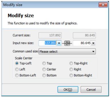
Например: «100 мм» означает увеличение изображения в равных пропорциях с шириной 100 мм, «2 times» (2 раза) означает увеличение изображения в равных пропорциях в 2 раза. Если необходимо ввести точный размер, нажмите непосредственно на кнопку «Scale», в отобразившемся диалоговом окне укажите новый размер и нажмите кнопку «ОК».
При состоянии меню сохраняется пропорция между длиной и шириной изображения. Если необходимо отдельно ввести значения длины и ширины, нужно кликнуть на кнопку , после чего ее состояние сменится на . Параметр «Scale center» позволяет определить соотношение между расположением нового и исходного изображений после процесса масштабирования. Например, при выборе пункта «Top left / Вверху слева» новое и исходное изображение будут выровнены по верхнему левому углу после изменения. Примечание: коррекция направляющих и отверстий не может быть выполнена при трансформации изображения.
16 2.3.2 Интерактивное геометрическое изменение.
Система CypCut поддерживает 3 вида интерактивной геометрической трансформации, включая интерактивное масштабирование, поворот, и зеркальное отражение. Перед выполнением данных действий, в первую очередь, необходимо выбрать изменяемые изображения, кликнуть на соответствующий пункт меню или кнопку, затем выполнить операции в соответствии с подсказками в нижней части экрана. Например, если нужно повернуть прямоугольник, взяв за основу его левый нижний угол, необходимо выполнить следующие действия: 1) выделить прямоугольник. 2) кликнуть маленький треугольник под кнопкой «Transform» и в открывшемся меню выбрать «Rotate / Поворот», после чего в нижней части экрана появится сообщение «Please specify base point / Укажите базовую точку». 3) переместите мышку в нижний левый угол, затем мышка автоматически зафиксируется в нижнем левом углу, как показано на изображении ниже:
4) кликните мышкой, появится всплывающее окно «Specify start point of rotation or input rotation angle / Укажите стартовую точку или введите значение угла вращения» в нижней части экрана. 5) для завершения действия введите число 45 и кликните Enter. Если угол вращения заранее не известен, но требуется повернуть прямоугольник в положение выравнивания с другим изображением, выполните первые четыре пункта, а вместо пункта 5 выполните следующие действия: 6) переместите мышку в нижний правый угол прямоугольника и кликните, чтобы выделить горизонтальную линию и взять ее как основу вращения прямоугольника. 7) на экране всплывет окно «Please specify end point of rotation / Укажите конечную точку вращения». После этого изображение будет вращаться вслед за перемещением мышки. Для завершения действия нужно кликнуть мышкой в конечной точке вращения, как показано на рисунке ниже: Действия по интерактивному масштабированию и зеркальному отображению сходны с действиями по вращению.
2.3.3 Быстрое перемещение и копирование
ПО позволяет быстро перемещать изображения, используя кнопки направления. После того, как изображения выбраны, нажмите кнопку направления, и изображения будут перемещены на расстояние в нужном направлении, параметры расстояния можно ввести в окне « » в нижнем правом углу экрана. Данная функция поможет быстро переместить изображения, затем сфокусироваться на редактировании других изображений, после чего вернуть перемещенные изображения в исходное положение. Благодаря точной настройке параметров исключены возможности отклонения в расположении объектов. Для копирования выбранных изображений требуется нажать Ctrl и кнопку направления. Например, при нажатии “Ctrl + →” (вправо), выбранные изображения скопируются в области на расстоянии 100 мм вправо.
2.4 Ввод координат и параметров.
В некоторых случаях можно выполнить чертеж при помощи ввода точных координат. Программа CypCut позволяет напрямую ввести координаты в следующем формате: ˂ координата Х˃ ˂запятая,˃˂координата Y˃. Например, если требуется ввести координаты (100, 100), нужно ввести только «100, 100». Введенные координаты и параметры будут отображаться синим. Большинство чертежных операций можно выполнить при помощи действий мышкой и прямого ввода координат. Ниже приведен пример создания прямоугольника с закругленными углами длиной 300 мм, шириной 200 мм и закруглением угла 25 мм. 1) необходимо кликнуть иконку « » на левой панели инструментов, после чего на экране появится всплывающее окно «Please specify start point / Укажите стартовую точку». 2) введите координаты «0, 0» и нажмите Enter, затем на экране появится всплывающее окно «Please Specify Cross Point / Укажите точку пересечения». 3) введите координаты «300, 200» и нажмите Enter, затем на экране отобразится всплывающее окно «Please Specify Corner Radius or [Fillet (F)] / Укажите радиус закругления угла или (радиус кривизны (F)». 4) введите «50» и нажмите Enter. Выполнение всех действий завершено, как показано на рисунке ниже:
2.5 Автоматическая фиксация.
Cypcut software system(CypCut for short) is a set of system software designed for plane laser cutting, including laser cutting process, common layout function and laser processing control, most of its functions are applied in graphics processing, parameter settings, custom cutting process editing, layout, path layer planning, simulation and cutting process control.Today I will introduce you to the operation instructions of CypCut’s main program.
Part 1 – Installation
You can contact the supplier to get the software installation program, or go to the official website of Baichu to download the installation program.
Before installing the software, please check whether your system meets the following minimum requirements.
- The operating system should be above Windows 2000.
- CPU with basic frequency above 1.0G
- The memory should be 512Mb at least.
- The VGA monitor should be more than 15 inches with a resolution of more than 1024*768.
- And it would be better to use 32-bit true color display.
- There should be two USB interfaces at least.
- If your operating system is vista-based (including Windows Vista, Windows 7, Windows 8, Windows 2008 Server), please run the system as an administrator as much as possible in order to avoid the possible errors.
After completing the inspection, you can start to install the software. You can just run the installerdirectly. If you want to install the program in Vista-based operating system, you should have
administrator permission so that it can run.
In order to prevent the program files from being modified during the installation process and ensure the normal installation of all drives, please close 360 security guards and anti-virus software in the system. Note: 360 security guards cannot guarantee that there are no viruses in the computer. If the computer has been infected by the viruses, while 360 security guards are running, it may point out that CypCut is a virus, and then cause CypCut not to run normally.
Part 2 – Starting
2.3.1 Desktop Shortcut
After installation, an icon shown on the right will appear on the desktop. The CypCut laser cutting control system will run after double clicking this icon.Please check whether the dongle has been inserted into the USB interface with normal operation before running CypCut. If the dongle detection fails, the system will enter DEMO mode, and you can use all other functions normally except the process control.
2.3.2 User Interface
The figure with black background in the center of the interface is the Drawing Board; while the white frame with shadows represents the machine breadth, and it displays with grids. The staff gauges at the top and the left of the drawing area and the grids will change with the zooming of the views, and in this way they can provide references for drawing. Above the interface from top to bottom one by one are Title Bar, Menu Bar and Toolbar. The toolbar is arranged with very obvious large icons in grouping and most of the common functions can be found here. The menu bar includes the menu “File” and five toolbar menus, namely “Home”, “Draw”, “Nest”, “CNC” and “View”, and toolbar display can be switched through selecting these five menus.There is a toolbar called “Quick Access Bar” at the left of the title bar, which can be used for fast creating, opening and saving a file; besides, undo and redo commands can also be finished quickly here.
At the left of the interface is “Drawing Toolbar”, which is called directly “Left Toolbar” in the following instructions. It provides the basic drawing functions, and the first five buttons are used to
switch the graphics mode, which includes selecting, node editing, order editing, dragging and zooming. The following other buttons respectively correspond to the corresponding graph and a new
graph can be inserted in the drawing board by clicking these buttons. At the bottom there are three shortcut keys, which are Align Center, Explode selected graphic, and Rounded.
At the right of the drawing area is “Process Toolbar”, which is called directly “Right Toolbar” in the following introduction. It includes a “Layer” button and seventeen color square buttons. “Layer”
dialog box can be opened by clicking the “Layer” button, and then most of the parameters can be set.

Each of the seventeen color square buttons corresponds to a layer, and when a graph is selected, the selected graph can be moved to the specified layer by clicking these buttons, when no graphs are selected, it means to set the default layer for the next drawing by clicking these buttons. The first white square indicates a special layer. When “un-exported Layer” is displayed, the graph on this layer will be shown in white and it cannot be processed. The last two layers are layers of first processing and last processing.
There are three scrolling displayed ribbon text windows below the interface. The left one is “DrawWindow”. The related prompting messages of all the draw instructions or input message will be
shown here. The middle one is “System Window”, and other system messages will be displayed here except drawing. Each message has time mark and they will be shown in different colors according to the importance of the message, which includes prompting, warning and error and so on. The right one is “Alarm Window”, in which all the alarm message will be displayed in red background and white text.
There is the Status Bar at the bottom of the interface, which can show different prompting messages according to different operations. There are some basic messages of drawn processing
graphics at the left, and some commonly used messages at the right of the status bar, including the location of the mouse, processing status and the location of the laser head. The latter one is the
fine-tuning distance parameter, which can move the graphs quickly by using direction keys. The final show is the type of control card.
The rectangular area at the right of the interface is called “Console”, and most common operations related to control will be done here. From top to bottom one by one are choices of coordinate system,manual control, work control, processing options and processing count.
2.3.3 Toolbar
The toolbar of CypCut uses a style called Ribbon. It puts the common functions by column and area, and also applies many large-size buttons for easy operation. The photo below will help you to
understand this new toolbar:

The whole toolbar is divided into five “pages”, which can be selected by the five menus “Home”, “Draw”, “Nest”, “CNC” and “View”. When selecting each menu, the pages related to the selected
contents will appear. Furthermore, the page “Being Processed” will appear during processing and it cannot be switched to other pages before stopping.
The toolbar of each page will be arranged again in multiple “Columns” according to the functions, such as “Base operation” and “Geometric transformation” and so on. The first buttons of the general columns are all in large size, and there is a small button“![]() ” at the lower right corners of some columns, which is called “Extending Button”, and a related dialog box can be opened by clicking this button.
” at the lower right corners of some columns, which is called “Extending Button”, and a related dialog box can be opened by clicking this button.
Note: there are small triangles below some large-size buttons, which are called “Drop-down Buttons”, a related “Drop-down Menu” will appear after pressing the button, and the menu can offer
richer operation options. When the mouse is moved to the top of the button, two obviously different rectangles will appear, the corresponding function of the button can be directly executed by pressing the upper part of the button, while a menu can be opened by pressing the lower part of the button.
If you have used Office 2007, Windows 7 or other procedures which use the Ribbon style before, you may have been very familiar with this arrangement. It does not matter even if you use it for the
first time, and we are sure that you will like this style soon.
2.3.4 File Menu
There is a special menu called “File Menu” at the upper left corner of the toolbar, and it contains some menu items related to the files. The menu can be opened by clicking the button “ ![]() ” as
” as
shown below:

Please note that at the right of the menu the recently used files are listed. While the files saved by CypCut are marked with the icon“ ![]() ” , and in this way it is convenient for you to find the designed documents of last time.
” , and in this way it is convenient for you to find the designed documents of last time.
The “Import” in the menu can be used to import another document to the drawing board on the basis that the existing graphics are not cleared. If you just would like to open an external file, please
directly use “Open”.
The menu “User Parameters” is used to set some parameters related to the using habits; and the menu “Backup Params” is used by users to backup all parameters as a compressed file; and the menu.
“BCS100 monitor” is used to monitor and display the interface of BCS100 Height controller in the software; while the menu “Diagnosis” is used for program diagnosis and monitoring. You can see the detailed version information of CypCut software by clicking “About” at the lower right corner.
2.4 Operation Process

2.4.1 Import Graphics
After clicking the button of opening files“![]() ” in the quick launch bar at the upper left corner of the interface, the dialog box of opening files will be popped, and then you can choose the graphic you
” in the quick launch bar at the upper left corner of the interface, the dialog box of opening files will be popped, and then you can choose the graphic you
need to open. There is a quick preview window at the right of the opening file dialogue box, and it can help you to find quickly the file you need.

If you hope to draw a part on the spot through CypCut software, please click the create button“![]() ”and then draw pictures with the buttons of the drawing toolbar at the left. See the details in related chapters.
”and then draw pictures with the buttons of the drawing toolbar at the left. See the details in related chapters.
2.4.2 Preprocessing
When importing the graphics, CypCut will automatically remove trivial and duplication, combine near as well as automatically smooth, sort and de-group. And usually you can start to set technical parameters without other handlings. If the automatic processing cannot meet your requirements, you can open the menu “File” and “User Parameters” for configuration. Generally the graphics to be processed based on the requirements of software as closed curves.
Therefore, if the files you opened include unclosed curves, the software will prompt you and the unclosed curves will be displayed in red. However, this function may be closed. Thus, if you would
like to look over the unclosed curves in the drawing board, you can click the buttons “ ![]() ” and “
” and “![]() ” under menu “View” in the toolbar to highlight them. You can also click the big button “Select” at the leftmost side of the toolbar, and then click “Select Unclosed Curve” to choose all of them. In some cases, you have to split the graphics manually, please click the button“
” under menu “View” in the toolbar to highlight them. You can also click the big button “Select” at the leftmost side of the toolbar, and then click “Select Unclosed Curve” to choose all of them. In some cases, you have to split the graphics manually, please click the button“![]() ” under “Optimize” in the common used menu and then click the mouse in the position where you need to split. When you need to merge the graphics, please select them and then click the button “
” under “Optimize” in the common used menu and then click the mouse in the position where you need to split. When you need to merge the graphics, please select them and then click the button “![]() ”.
”.
2.4.3 Technical Design
In this step you may use most of the functions of “Technical Design” in the common used menu, and Combine near they include setting lead lines, setting compensation and so on. Big size button “![]() ” can be used to set lead lines, and the button “
” can be used to set lead lines, and the button “  ” is used to set lead seal over, lead seal gap or lead seal parameters. The button “
![]() ” is used for cutting compensation; the button“
” is used for cutting compensation; the button“![]() ” can insert micro joint of not cutting into the graphics; the button “
” can insert micro joint of not cutting into the graphics; the button “![]() ” can reverse a single graph; and the button “
” can reverse a single graph; and the button “![]() ” is for setting a cooling point in the graph. Clicking the button“
” is for setting a cooling point in the graph. Clicking the button“![]() ” and then clicking the position where you hope to set as the start of the graphics, you can change the start of the graphics; if you click outside the graphics, and then click on it again, you can draw a lead manually.
” and then clicking the position where you hope to set as the start of the graphics, you can change the start of the graphics; if you click outside the graphics, and then click on it again, you can draw a lead manually.
You can press Ctrl+A to select all the graphics as quick start tutorial, then click the button “Lead” and set the parameters of the lead lines, and then click OK. In this way the software can search
suitable positions to add the lead automatically according to your settings. You can conduct the Lead Lines Check by clicking the small triangle below the button “Lead” and selecting “Check lead lines”. When select “Distinguish inner and outer mold”, lead can be automatically optimized according to inter and outer mold.
You can set detailed cutting technical parameters by clicking the button “ ![]() ” in the toolbar at the right. The dialog box “Layer Parameter Settings” contains almost all the parameters related to the cutting effect.
” in the toolbar at the right. The dialog box “Layer Parameter Settings” contains almost all the parameters related to the cutting effect.
2.4.4 Lead Planning
In this step the graphics will be sorted as required. You can conduct automatic sorting by clicking the button “![]() ” under the “Home” or “Nest” menu, while you can select the ways of sorting and control whether it is allowed to change the direction of the graphics and automatically distinguish inner and outer mold during the automatic sorting by clicking the small triangle under the
” under the “Home” or “Nest” menu, while you can select the ways of sorting and control whether it is allowed to change the direction of the graphics and automatically distinguish inner and outer mold during the automatic sorting by clicking the small triangle under the
button.
If the automatic sorting cannot meet the requirements, you can click the button“ ![]() ” in the toolbar at the left to enter the manual sorting mode, and click the graphics with mouse one by one, and in this way you can set the working order . You can specify the order between these two graphics through pressing the mouse and drawing a line from one graph to another.
” in the toolbar at the left to enter the manual sorting mode, and click the graphics with mouse one by one, and in this way you can set the working order . You can specify the order between these two graphics through pressing the mouse and drawing a line from one graph to another.
You can fix the order of several sorted graphics by selecting them and then clicking “![]() ” button under “Home” or “Nest” menu. The following automatic sorting and manual sorting will not influence the graphics inside the “Group”, and the “Group” will always work as a whole.
” button under “Home” or “Nest” menu. The following automatic sorting and manual sorting will not influence the graphics inside the “Group”, and the “Group” will always work as a whole.
You can conduct automatic sorting for the graphics within the group by selecting a “Group” and then clicking the right key with selecting “Group Sort”.
2.4.5 Inspection before Processing
Before the actual cutting, you can check the working route. You can align graphics by clicking align button; you can view the processing order quickly by dragging the interactive preview progress
bar under “Draw” menu as shown below, and you can view the processing order of the graphics one by one by clicking the interactive preview button.

You can simulate process by clicking the button “![]() ” on the console, and you can adjust the speed of the simulation processing through the function “simulation speed” on the page “
” on the console, and you can adjust the speed of the simulation processing through the function “simulation speed” on the page “ ![]() ”.
”.
2.4.6 Actual Processing
Please note that this step must be done on the actual machine with the support of dongle and the control card. Before formal processing, you need to match the graphics on the screen with the machine. You can find the relative positional relationship between the upcoming processing graphics and the machine breadth on the screen by clicking the left button “ ![]() ” above the “Console”.
” above the “Console”.
This corresponding relationship is calculated in accordance with the dock point markers on the screen and the position matches of the machine laser head. Some common coordinate markers on the screen are shown in the photo below. When you click “Preview”, the “Dock Point” will be moved to the “Laser Head Position” and visually parallel move occurs in the graphics on the whole.
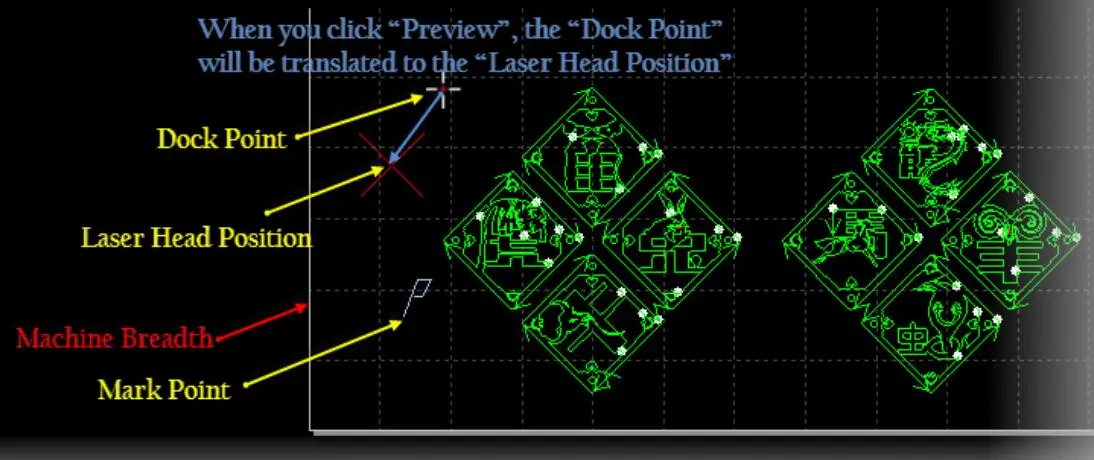
If the “Laser Head Position” shown by the red cross cursor does not match the actual laser head position of the machine, please check whether the position of the machine origin is correct, and it can be corrected through “Numerical Control”—“Go Origin”. After previewing, if you find that the graphics are outside the machine breadth wholly or partially, it means that it may exceed the range of travel during processing.
You can change the relative relationship between the graphics and the dock points by clicking the button “ ![]() ” under “Home” menu. For example, if the laser head is at the lower left corner of the upcoming processing work-piece, you can set the lower left corner as the dock point and so forth.
” under “Home” menu. For example, if the laser head is at the lower left corner of the upcoming processing work-piece, you can set the lower left corner as the dock point and so forth.
If there is no error on the screen after checking, you can click the button “![]() ” on the “Console”, and the software will control the machine to go around the outer frame of the upcoming processing graphics so that you can check whether the working positions are correct. You can also click the button “
” on the “Console”, and the software will control the machine to go around the outer frame of the upcoming processing graphics so that you can check whether the working positions are correct. You can also click the button “![]() ”, and the machine will run completely without laser along the graphics which will be processed so that you can check more carefully whether there may be any impropriety in the processing.
”, and the machine will run completely without laser along the graphics which will be processed so that you can check more carefully whether there may be any impropriety in the processing.
Finally please click the button “ ![]() ” to start the formal processing, and you can click the button“
” to start the formal processing, and you can click the button“ ![]() ” to suspend the processing. During the suspension, you can control the laser head to go up and down manually, and switch the laser, gas and so on manually, besides, you can also trace back along the working route through the buttons “
” to suspend the processing. During the suspension, you can control the laser head to go up and down manually, and switch the laser, gas and so on manually, besides, you can also trace back along the working route through the buttons “![]()
![]() ”. You can continue to work by clicking the button “
”. You can continue to work by clicking the button “ ![]() ”.
”.
You can click the button “![]() ” to stop the processing and the laser head can automatically return to the corresponding point according to your setting. As long as you do not change graphics or start new processing, when click the button “
” to stop the processing and the laser head can automatically return to the corresponding point according to your setting. As long as you do not change graphics or start new processing, when click the button “ ![]() ”, the system will 11 CypCut Laser Cutting Control System allow you to locate to the position you stopped last time; when click the button “
”, the system will 11 CypCut Laser Cutting Control System allow you to locate to the position you stopped last time; when click the button “![]() ”, the system will allow you to continue the processing from the position of last stopping.
”, the system will allow you to continue the processing from the position of last stopping.
Part3 – Graphical Operation
CypCut provides the common drawing functions, which can be available easily from the drawing toolbar on the left. The use of these functions is similar to AutoCAD mostly, and it is very intuitive.
Thus, this Manual will not introduce them in detail, if you have any questions, please feel free to contact the customer service staff or Friendess Electron for help. We will introduce some special
graphical operations of CypCut as the software for laser cutting.
3.1 Graphical Display Effect
“View” in the first column under “Home” menu has multiple buttons which can help to control the display effect, as shown below:

After you click the buttons in the figure above, the display will take effect immediately and then you can find the changes in the display effect in the drawing board. Please pay attention to the display changes of the buttons themselves, if the ground color is light yellow, it shows that the corresponding effect has started; otherwise, it indicates that the display effect does not start yet. For example, in the on- state “ ![]() ”, the arrow will show the graphical processing path in the drawing board; while in the off state “
”, the arrow will show the graphical processing path in the drawing board; while in the off state “![]() ”, the arrow will disappear.
”, the arrow will disappear.
When a graph is selected, by clicking the button “![]() ”, the graph will be shown in the center of the screen. If no graphs are chosen, please just click the button directly, and the whole graphs will be displayed in the center.
”, the graph will be shown in the center of the screen. If no graphs are chosen, please just click the button directly, and the whole graphs will be displayed in the center.
By clicking the button “ ![]() ” in the lower right corner of the column, a dialog box will be opened, and it can conduct more detailed control for the drawing board, including turning on and off the auto attach key-points, turning on and off the ruler and controlling the pick precision of mouse.
” in the lower right corner of the column, a dialog box will be opened, and it can conduct more detailed control for the drawing board, including turning on and off the auto attach key-points, turning on and off the ruler and controlling the pick precision of mouse.
The views can be zoomed by scrolling the mouse wheel in the drawing board. By clicking F3, allthe graphs will be shown in the center of the screen. By clicking F4, the machine breadth range will be displayed in the center. The above operations can be selected by clicking the right key of the mouse with selecting “Zoom” in the drawing board.
3.2 Selection of Graphics
CypCut offers a variety of graphical selection methods. The basic operation is “Click Selection”, and the graphs will be selected just by clicking the mouse on the graph. Another more common
operation is “Box Selection”; by this way, a translucent box can be formed by dragging the mouse in the screen to select the graphs. There are two kinds of box selection. When dragging the mouse from left to right, it shows a blue translucent rectangle with solid line and only the graphs covered completely in the rectangle box can be selected; when dragging the mouse from right to left, a cyan translucent rectangle with dotted line will appear and as long as any part of the graph is in the box, the graph will be selected.
The schematic diagram of these two options is shown below. The left one is the option from left to right and BC will be selected; while the right one is from right to left, and ABCD all will be selected. Flexible use of these two methods can help you to choose the graphs you need in a more convenient way.

No matter it is “Click Selection” or “Box Selection”, if you press “Shift” while you make a selection, you can add or cancel selected graphics without the need for clearing the original selection.
When you click the button “Select”, a drop-down menu will appear, through which you can conduct senior selection operation, including the selection of unclosed graphics, similar graphics, all
outer or inner mold, and all graphics smaller than specific size. Among them, “Select similar curve” allows you to select all the graphics which looks close to each other on the drawing board. For
example, you may select all the circles with a diameter of 5mmm by selecting a circle with a diameter of 5mm and then clicking “Select similar curve”.
3.3 Geometric Transformation
The column “Geometric Transformation” under “Home” menu provides abundant geometric transformation functions. Select wanted transformation graphics before applying. Most of the
commonly used geometric transformations can be completed only by clicking the drop-down triangle under “Transform”, for examples: Mirror, Rotate, Align and Scale.
3.3.1 Size Modification
CypCut provides 7 fast size transformations, which can be completed by the drop-down menu below the button “Scale”. Click the small triangle under “Scale” button, you can open a drop-down
menu, providing selected graph operations of size transformation, as shown below.

For examples: “100mm” means to zoom graphics in equal proportion with a width of 100mm, “2 Times” means to zoom graphics in equal proportion by 2 times. If you want to input accurate size, please directly click the button “Scale”, the following dialog box will appear, then you can input the new size and complete the size transformation by clicking “OK”.
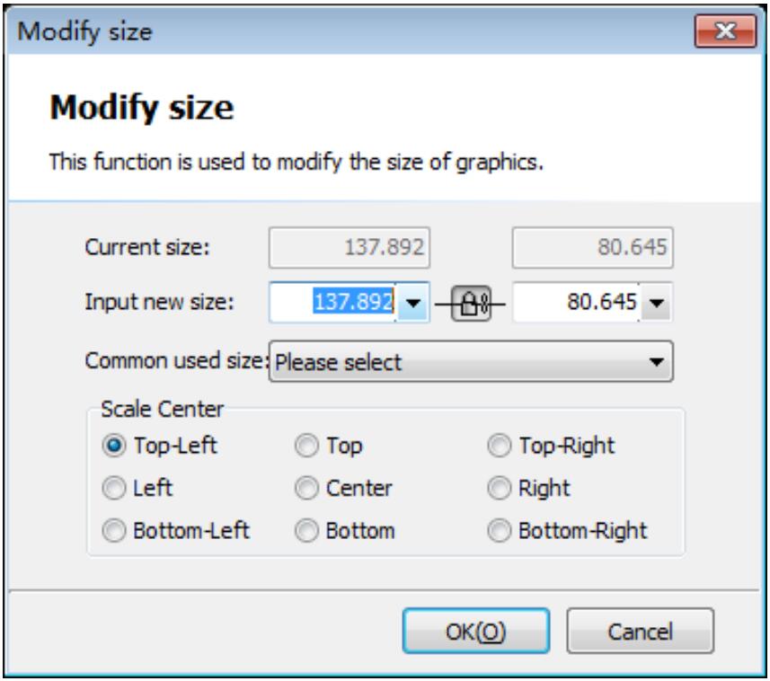
When the status of lock of the interface is ![]() , the length and width are locked as the proportion of the original graphics. If you want to separately input length and width, you can cancel
, the length and width are locked as the proportion of the original graphics. If you want to separately input length and width, you can cancel
the cancel lock status by clicking the button![]() , and then the button will become
, and then the button will become ![]() .
.
“Zoom Center” can determine the location relations between the new graphics and original graphics after being zoomed. For example, when you select “Upper Left”, it means that the new graphics and original graphics are aligned in accordance with the upper left corner after the transformation, and other parts are zoomed by taking the upper left as a basis.
Note: The lead and slotted compensation set for graphics cannot be transformed at the same time, and the numerical value of lead and slotted compensation will not change after the size is
changed.
3.3.2 Interactive Geometric Transformation
CypCut provides 3 kinds of interactive geometric transformation, including interactive zooming, rotation and mirror, and you can achieve more detailed geometric transformation through them.
Before doing these operations, you need to firstly select the operation graphics, click the corresponding menu or button, and then conduct operations in accordance with the tips at the bottom of the screen.
For example, if you want to rotate a rectangle by taking its lower left corner as a basis, you can conduct the operations as follows:
1) Firstly, you need to select the rectangle for operation;
2) You need to click the small triangle below the “Transform” and opening the drop-down
menu, and select “Rotate”, and then there will be a prompt “Please Specify Base Point” in the lower part of the screen;
3) You need to move the mouse to the lower left corner, and then the mouse will be automatically absorbed to the lower left corner. As shown below:

4) You need to click the mouse, and then there will be a prompt “Specify Start Point of Rotation
or Input Rotation Angle” at the bottom of the screen;
5) You can complete the operations by directly inputting 45 and then clicking Enter.
If you do not know the angle of rotation in advance but want to rotate the rectangle to the position aligning with another graphic, then the first four steps is the same as above, please conduct the following operations from step 5:
6) Please move the mouse to the lower right corner of the rectangle, at this moment, click to form a horizontal line and take it as the start line of rotation.
7) The screen shall appear the prompt “Please Specify End Point of Rotation”. Then the graphics will rotate with the mouse when you move the mouse, and you can complete the operations by
clicking the mouse at the expected end point of rotation. As shown below:
The operations of interactive zooming and mirror are similar with this, so there is no further explanation.
3.3.3 Quick Translation and Copy
CypCut software allows you to translate the graphics quickly by using the direction keys. After the graphics are selected, when you press any direction key, the graphics will be translated to a distance in the corresponding direction, and the distance parameters can be inputted in the window “![]() ” at the lower right corner of the main interface. This function can help you to shift away a graphic temporarily and quickly, then you can focus on the design of other graphics, and later you can move it back to the original place rapidly. Since the fine-tune distance parameters can be controlled precisely, you do not have to worry about the deviation of the graphical positions.
” at the lower right corner of the main interface. This function can help you to shift away a graphic temporarily and quickly, then you can focus on the design of other graphics, and later you can move it back to the original place rapidly. Since the fine-tune distance parameters can be controlled precisely, you do not have to worry about the deviation of the graphical positions.
when you press “Ctrl + Rightward”, the selected graphics will be copied at the position with a distance of 100mm on the right.
3.4 Input of Coordinates and Parameters
In some cases, you may hope to draw with precise coordinates. And CypCut allows you to input the coordinates directly and the input format of coordinates is as follows: <X coordinate><comma,><Y coordinate>. For example, if you would like to input the coordinates (100, 100), you can only input “100, 100”. And the inputted coordinates and parameters will be shown in blue.
Most of the drawing operations allow both mouse operation and inputting coordinates directly.
Below is an illustration for drawing a rounded rectangle with a length of 300mm and a width of 200mm and a fillet of 25mm.
1) You need to click the icon “![]() ” on the left toolbar, and then “Please Specify Start Point” will be prompted on the screen.
” on the left toolbar, and then “Please Specify Start Point” will be prompted on the screen.
2) You need to input the coordinates “0, 0” and press Enter, and then “Please Specify Cross Point” will be shown on the screen.
3) You need to input the coordinates “300, 200” and press Enter, and then “Please Specify Corner Radius or [Fillet (F)]” will be shown on the screen.
4) You need to input 50 and press enter. All the operations are completed, as shown below.

3.5 Automatic Adsorption
Cypcut will provide the functions of automatic adsorption during drawing according to the needs, including automatic adsorption to the grids, adsorption to the critic points of the graphics,
adsorption to the borders of the graphics and so on.
You can close the functions of automatic adsorption, and the operation steps are as follows: click the menu “ ”, select “User Parameters”, then select the tab “Drawing Board” in the opened dialog box, and finally cancel the option“ ”. The precision of automatic adsorption can also be set in the above dialog box.
3.6 Text Input
CypCut supports text input and text conversion to curve. After clicking the button“ ” on the drawing toolbar at the left, you can insert text in the position where you hope by clicking the mouse
and the newly inserted text will be selected automatically.
After selecting the text at any moment, a new page “Text” will appear in the toolbar, and you can modify the content, the style and the size of the text and so on using it. As shown below:

Please note that once the text is converted to the curves, the above option cannot be used any longer. If you would like to design a text with specific font and special effect, please convert it to curves after you design it well.
3.7 Graphical Optimization
When importing the external graphics, CypCut can optimize the graphics automatically. If you have to optimize them manually, you can use the right functions in the toolbar. As shown below:

Please select the graphics to be processed, click the corresponding buttons, and then operate according to the prompts.
3.7.1 Smooth
Please select the polylines to be optimized, then click button![]() , a prompt “Smooth the selected curve according to a given precision” will be shown on the dialog box. Please input the
, a prompt “Smooth the selected curve according to a given precision” will be shown on the dialog box. Please input the
expected curve smoothing precision and then click ok.
The contrast between the original curve and the smoothed curve is as shown below. In order to facilitate the observed effect, the curve smoothing precision value entered here is greater. Please use
the actual value according to required processing precision.

3.7.2 Split
Split is to divide the closed graphic into two graphics and the user can edit these two graphics separately. Please click the button “![]() ”, and then click the mouse in the position where you need to split. The process of curve split can be carried out continuously as far as ESC cancels the command or it is switched to other commands.
”, and then click the mouse in the position where you need to split. The process of curve split can be carried out continuously as far as ESC cancels the command or it is switched to other commands.
3.7.3 Remove Tiny Objects
Sometimes the imported graphics may include the curves which are visually imperceptible, which causes the display size to become very small, or move to an abnormal position when processing.
These graphics can be deleted through the function “Remove trivial”. You may click the button “Remove trivial”, set the size range of the graphics, and then confirm the operation. The graphics
smaller than this size will be deleted and other curves will be retained.
3.7.4 Remove Duplicated Curves
This function can be used to delete the visually overlapping lines and only leave one. You can search and clear all the graphics by clicking “Remove Duplication”
3.7.5 Combine Near
The graphics drawn by using AutoCAD often include the graphs which connect visually while do not connect actually. Through connecting near, they can be combined. Please select the graphics to be merged, then click “ ![]() ” and input merging accuracy, lastly confirm the operation.
” and input merging accuracy, lastly confirm the operation.

Note: The end points of the graphics in visual may be not the ones in geometric, and the excess backtrack lines may exist in the end points, and these graphics need to be split and deleted firstly
through “Split”, and then can be combined.
This chapter will describe the related functions of technical parameters provided by Cypcut.Because most of the technical parameters have direct relations with the materials to be cut, the used
lasers and air pressure, you need to set the parameters according to the actual technical requirements.
All the parameters mentioned here including the ones in the graphics should only be used as examples rather than being considered as guidance parameters.
Warning! The inappropriate or incorrect parameters may result in poor cutting effect or even damage to the machine, so please set the parameters carefully.
3.1 Lead lines
3.1.1 Distinguish inner and outer mold
When opening the external files such as DXF and so on, CypCut can distinguish inner and outer mold automatically. If the graphics are modified during editing and they result in the changes in the relationship between inner and outer mold, you can click the button “Auto Sort” when the inner and outer mold need to be distinguished again, and then any way of sorting can distinguish them, which is required to select “Distinguish inner and outer mold when sorting”, locating at the drop-down menu of “Auto Sort” button with default selection. Also, you can directly click drop-down triangle button of “Lead” and select “Distinguish inner and outer mold.
CypCut distinguishes inner and outer mold in accordance with the surrounded relations, and it always takes the outermost layer as outer mold, while the next one as inner mold, then outer mold
and so forth. Besides, an unclosed graphics cannot form a layer. If you would like to start outer mold from one layer, you can choose all the graphics from this layer and inside it, group them, and then distinguish inner mold and outer mold through “Group Sort”.
When adding the lead lines, the external layer is yang cut, so it will be led in from the outside; the internal layer is inner mold and will be lead in from the inside. When set inner and outer mold
manually, please select the graphics to be set, and then click the buttons “![]() ”under “Home” menu.
”under “Home” menu.
3.1.2 Automatic Lead Lines
Please select the graphics to be set with lead lines, click the icon “ ![]() ” under “Home” menu, then set the lead lines parameters in the popped window. As shown below:
” under “Home” menu, then set the lead lines parameters in the popped window. As shown below:
The supported lead types include Arc, Line and Line + Arc, while the supported parameters consist of lead type, lead angle, lead length and lead radius. You can also choose whether to add a
small hole at the starting point of Lead lines.
When you select arc leading, the end of the circular arc needs to keep in tangent with the graphics to be cut (no matter how big the set angle is). As shown in the right figure. In fact, the angle
set at this moment is an included angle between the connecting line of the start point and the end point of the lead line and the graphics to be cut. The lead out lines are similar to it.

Please note that automatically select the appropriate lead position, it will search preset priority long side or priority vertex in order to determine lead position, thus the previous parameters of the
graphics such as lead position and type will be covered. If you have a fixed requirement for the lead position, you can choose to set unified position according to the total length of graphics or un-change the lead position, and only change the type option.
3.1.3 Manually Set lead lines
You can modify the leanin manually by clicking the button “ ” on the toolbar. If you click on the graphics, you can change the position of the lead lines; however, you cannot modify the angle and the length.

Firstly please click (point A, yellow point) outside the graphics, then click (point B, red point) on the graphics, in this way you can draw a lead line from point A to point B.

3.1.4 Check the Lead lines
You can click the small triangle below the button” Lead”, and then select “Check Lead” so that you can check the lead lines which are set already. This function can shorten the lead lines with too
much length, and thus prevent them from intersecting with other graphics. Click “Distinction inner and outer mold”, you can determine the specific lead position according to set inner and outer mold.
3.1.5 Lead Seal, Gap and Over
There are three buttons, as  , in “Technical Design” under “Home” menu, which are used to set lead seal, gap and over. Please select the graphics you need to set, and then click the
corresponding buttons. The size set of “Gap” or “Over” can only be valid when resetting gaps or over cut later, and the size which has been set before will remain unchanged.
3.2 Cutting Compensation
Please select the graphics to be compensated, and then click the button “ ” on the toolbar for cutting compensation.
The cutting width will be obtained in accordance with the actual cutting results. The compensated track will be shown in white on the drawing board and the system will run along the
compensated track during processing. The compensated original drawing will not be processed and will be displayed on the drawing board only in order to facilitate operation.
The direction of cutting compensation can be selected manually. It can also be judged automatically according to outer mold or inner mold. Outer mold needs outward compensation, while
inner mold needs inward compensation.
During the process of cutting compensation, you can select to translate the corner in the form of round angle or right angle. As shown below:

In the figure the green is the original, the white is the compensated track, and the light yellow is the vertical lines drawn from the corner. From the figure you can find that the cutting edges can
coincide with the original after both sides of the vertical lines are compensated, while the corner needs transition. Usually round angle transition can ensure that the cutting edges can still coincide
with the original and run more smoothly during transition.
To facilitate the selection, you can edit the common compensation value in the general configuration.
In order to clear compensation, please select the needed graphics, then click the button “Clear”and choose “Clear Compensation”.
3.3 Micro Joint
“Micro Joint” can be used to insert a micro joint into the track which will not be cut. When cutting to here, the laser will be closed; however, whether closing the gas and the follower is determined by the related parameters of short-distance vacant move during cutting. Micro joint is shown as a gap on the drawing board. As shown below:

You can add a micro joint by clicking at the position of the graphics needed to add micro joints by clicking the button “ ![]() ” on the toolbar,. You can insert multiple micro joints by clicking continuously until you press ESC to cancel the command or switch it to other commands.You can not only click on the graphics but also click on the compensated track to insert micro joints.
” on the toolbar,. You can insert multiple micro joints by clicking continuously until you press ESC to cancel the command or switch it to other commands.You can not only click on the graphics but also click on the compensated track to insert micro joints.
Please directly enter the length parameter of the micro joint in the drawing window at the bottom of the software, and the new parameters will be valid for the following operations after setting.
Except adding the micro joints manually, CypCut also provides the function of inserting micro joints automatically. Users can click the “ ![]() ” button by clicking the small triangle button in the right corner of “Micro Joint”, set the parameters in the popped dialog box, and thenconfirm it. You can select “adding by quantity”, for example, you can add ten micro joints to each graphic; or “adding by distance”; for example, you can insert a micro joint every 100mm.
” button by clicking the small triangle button in the right corner of “Micro Joint”, set the parameters in the popped dialog box, and thenconfirm it. You can select “adding by quantity”, for example, you can add ten micro joints to each graphic; or “adding by distance”; for example, you can insert a micro joint every 100mm.
The graphics may be divided into paragraphs through “Micro joint”. If you want to modify some separation section alone, you can click the “explode MicroJoint” button under the “Micro Joint”
drop-down menu. Unclosed graphics after “Micro Joint” operation will be regarded as a separate entity for modification.
In order to clear the micro joints, users need to select the needed graphics, then click the “Clear”button and choose “Clear Micro Joint”.
3.4 Cooling point
Click the “![]() ” button in the “Home” menu. When click on the corresponding position in the graphics, you can set a cooling point at that location. When cutting is implemented to
” button in the “Home” menu. When click on the corresponding position in the graphics, you can set a cooling point at that location. When cutting is implemented to
the cooling point, laser will be off and blow will be delayed according to cooling point corresponding settings in the global parameter. Later, laser will be on and operate normal cutting. Cooling point displayed as a solid point in the drawing board, as shown below:

Cooling points can also be inserted multiple by continuous clicking as well as Micro Joint.
Cooling points can still be added after operate the process of micro joint and compensation and so on. Cooling point can be deleting by pressing Shift and then clicking the cooling points.
3.5 Group
“Group” in CypCut refers that multiple graphics and even multiple “Groups” are combined together to form a “Group”, and the entire “group” will be regarded as a whole. Within the “Group”,
the order, the positional relationship between the graphics and the layers are all fixed and they will not be influenced during sorting, dragging and other operations.
Please select the graphics which you need to form a group, and then click the button “ ” to combine the selected graphics to a group. If you need to cancel the group, please select the “Group”
button, which has changed to “ ” button. If you would like to explode all the groups on the drawing board, please click the small triangle below “Group”, and then select “Explode Graphics”.
If there is a graphic which can contain all the other graphics in the group, it can be called the outer contour. The “Group” with outer contour will be regarded as a “Part”.
Although CypCut software allows you to group any graphics and operate them as a whole, we still recommend the users to use the function of group “logically” and only group the graphics which
meet the logical conditions of the “part” as much as possible. From now on we may use these two terms “group” and “part” indiscriminately.
Please note that CypCut software will always group the graphics with “Coedges” to ensure the integrity of these graphics. Furthermore, the result of bridging one “Group” with other graphics or
“Groups” must be a “Group” and it can also ensure the integrity of the graphics.
3.5.1 Sorting of Group
The part will be regarded as a whole when being sorted, and it will be involved in sorting with the outer contour or the first graphic as the basis. The graphical order within the part will not change
during sorting.
If you need to sort the graphics within the group without exploding the group, you can select the group, click the right key, and then choose “Sort in Group”.
The operation of “Sort in Group” will not change the graphical order of the sub-group within the group. The order of “Sort in Group” only has the relations with the geometrical properties of the
graphics, while no relation with the layer to which it belongs. During the sorting, it will distinguish inner and outer mold automatically according to the geometrical containing relations.
3.5.2 Processing of Group
The group (the part) will be considered as a whole during processing, and it will be finished by continuous work. No other graphics will be inserted during processing. Even if the group (the part)
includes the graphics at multiple layers, it will be processed successively. Pre-piercing in group also follows this rule.
Please note that no matter what the graphical order within the part is, the outer contour of the part will always be processed finally. Please sort before processing.
3.6 Scanning
When the graphics to be cut are regular (such as rectangular, full circle, polygon) and possess a certain regular arrangement, you can connect the cutting line segment with same direction by
scanning to conduct flight cutting, which will greatly improve the cutting speed and save cutting time.
It recommends that users sort graphics needed to be scanned before scanning. This operation can optimize the path of scanning and save move time.
Click ” ![]() ” button under “Home” menu and then enter the fly cutting parameters setting interface.
” button under “Home” menu and then enter the fly cutting parameters setting interface.
The starting position is to set the starting position of fly cutting. The minimum length of scan line refers to the minimum segment length of actually cutting after fly cutting. If the segment length of actually cutting after fly cutting is less than a given “minimum length of scan line “, the fly cutting does not give any results, and prompt “It does not detect any curve to meet the fly cutting conditions.” At this case, it recommends increase the parameter value of “minimum length of scan line “.
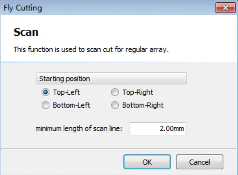
“ Lines scan” under “Scan” button under applies to rectangle and the straight line with same direction, and “Circlescan ” applies to arcs and circles of natural fly cutting. If you choose
“Arc sort before scan”, circle or arc will be sorted from top to bottom and then conduct fly cutting.
The graphics after fly cutting will automatically become a group. The example of fly cutting and its partial enlarged detail is shown as below:

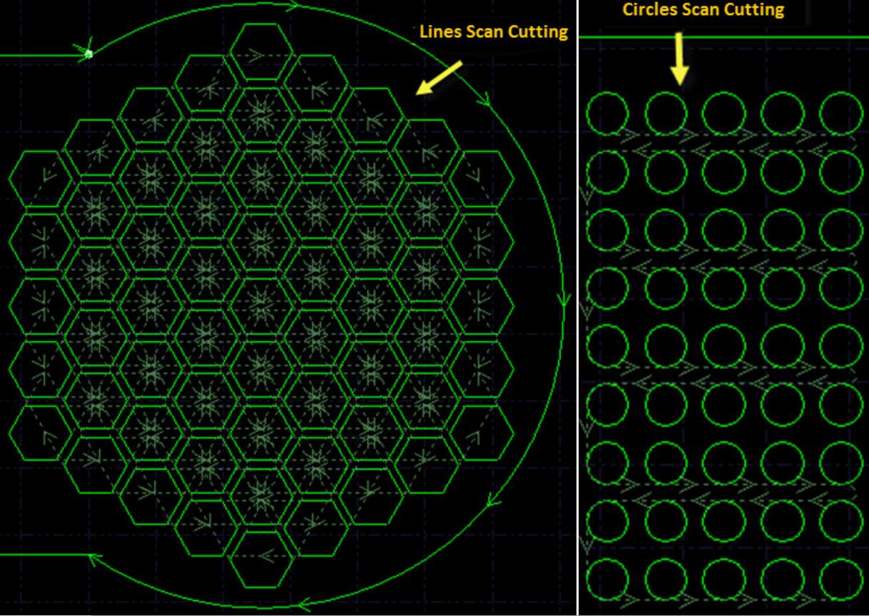
3.7 Coedge
It can save a lot of processing length and improve efficiency by merging the workpieces with same edges. In CypCut, when the boundary distance between two graphics is less than 0.1mm, the
two graphics can use the same edge. The function of automatic adsorption provided by CypCut will drag these two graphics together for coedge.
CypCut Laser Cutting Control System 28 After selecting two or more graphics which you need to coedge and then clicking the button “ ![]() ” on the toolbar, CypCut will try to coedge the selected graphics. If the selected graphics cannot meet the conditions of coedge, the window “Draw” at the lower left corner of the interface will display a prompted message.
” on the toolbar, CypCut will try to coedge the selected graphics. If the selected graphics cannot meet the conditions of coedge, the window “Draw” at the lower left corner of the interface will display a prompted message.
At present CypCut only supports to coedge the four sides of the graphics, and it cannot coedge the straight lines of the recesses within the graphics.
The graphics involved in coedge will be combined to form a “Group” after coedge. If they meet the requirement of the “Part”, the frames of them will be shown in bold like the right figure. If
the graphics involved in coedge include other graphics such as small holes, please combine the graphics and all the interior graphics together to form a group firstly, then coedge them; otherwise, the relationship between the interior graphics and the coedged group will become meaningless, and it will be difficult to determine the processing order and the relations of the internal and external dies
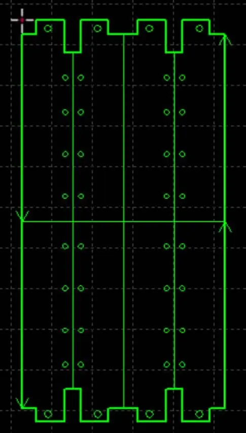
3.7.1 Coedge Automatic Adsorption
In CypCut, when you drag the graphics to the position where you may coedge them, CypCut will try to adsorb automatically and display the corresponding prompted message. You can drag together the two graphics which you need to coedge very easily, and the function of automatic adsorption will help you to locate them quickly when they become close to each other. Even when you select many graphics and drag them together, it can also locate them rapidly.
Once the two graphics are dragged together and they have the same edges, you can finish the coedges just by selecting them and clicking the button “Coedge”. If you would like to disconnect and
continue to edit the coedged “Part”, or set their order, please select “Part”, and then click “Degroup” under “Home” menu. You can combine them again through the button “Group” after editing.

3.7.2 Compensated Coedge
If you hope to still retain the cutting compensation after coedge, firstly please compensate the graphics which you need to coedge, and then coedge them. In any case, “Coedge” will keep the
processing track unchanged. If the coedged graphics contain compensation, the compensated track will be retained after “Coedge” and the original will disappear. As shown below.

In fact, in the figure above, the original A cannot be coedged with the graphic B, and only the compensated track P can be coedged with it. Even if you move the graphic B to the position near to
the original A, you still cannot coedge them because it is not the track to be processed.
3.8 Bridge
When a workpiece consists of many parts and you do not hope to scatter them after cutting, you can connect them through “Bridge”. Besides, this function can also reduce the pierce count. Multiple use of the function “Bridge” can also achieve the effect of “One-stroke” for all the graphics.
To bridge two graphics, please click the button “ ![]() ”, and then draw a line on the screen. And all the graphics intersected with it will be bridged together two by two. As shown below:
”, and then draw a line on the screen. And all the graphics intersected with it will be bridged together two by two. As shown below:

Bridge needs to specify two parameters. The first parameter specifies the maximum distance between two adjacent curves, and you can bridge them when the distance between two graphics is
less than the specified parameter. The second parameter specifies the width of bridge.
Please note that the graphics will become a whole after bridging. Maybe any part will not be cut before completing the “One-stroke” cutting, so you need to pay more attention to the change of the
heat affecting.
3.9 Nest
Nest function is used for reasonably arranging given parts on the plate with maximum utilization. CypCut not only supports nest through a key, but also provides a number of optimization parameters for you to make fine adjustments, such as: Gap, Plate Margin, Rotate Angle, Auto coedge and Create remnant and so on. Click “![]() ” button in “Home” page or “Nest” page to achieve this function. Please specify certain size plate before nesting. You can draw or import a graphic, select it, choose ”
” button in “Home” page or “Nest” page to achieve this function. Please specify certain size plate before nesting. You can draw or import a graphic, select it, choose ” ![]() ” button under “Nest” page, and then click “Set as plate”; Or select the graphics and click right key to select “Set as plate”. You can also click “AutoNest” button to set the length, width and count of standard plate in Auto Nest interface. Similarly, the number and parts can also be set in the similar method. The graphics before nesting is shown as below:
” button under “Nest” page, and then click “Set as plate”; Or select the graphics and click right key to select “Set as plate”. You can also click “AutoNest” button to set the length, width and count of standard plate in Auto Nest interface. Similarly, the number and parts can also be set in the similar method. The graphics before nesting is shown as below:

Auto Nest needs to set some parameters. “Gap” means setting a size not smaller than the distance between the parts and components; “Plate Margin” parameter specifies the plate border of parts
nesting remained; “Rotation Angle” refers to the adjustment angle of rotating parts during nesting, and in the case of not allowing to have relative rotation between parts and plates, lease select “prohibit rotation”; “Nesting direction” means a direction where the parts is close to the plates.

“Nesting strategy” means the strategy that is used to calculate the results of nesting by the program. Currently, auto nest offers five strategies:
Search pattern: Nesting depends on searching shape-matched parts of outline to be ranked space, and nesting results is relatively close between parts.
Stack pattern: The nesting strategies that parts occupied space height is in average growth; when the nesting result is that height of space occupied by parts is lower and more average, larger rectangle remnant can be generated.
Array pattern: Arrange parts into the plate by array pattern when parts have fewer types; It is recommended to use this strategy, especially when single part nesting.
Rectangular pattern: Arrange parts thorough rectangular pattern with the same kinds of parts form into a rectangular block; the nesting results of the local and overall layout are more neat, fit for
parts similar to rectangular pattern.
Sequential pattern: Nest parts in plates from large to small. Graphical after nesting will also have a certain optimization options: select “![]() ” will automatically optimize graphics after nesting, but also will consume more time, you can choose according to the actual situation; “
” will automatically optimize graphics after nesting, but also will consume more time, you can choose according to the actual situation; “![]() ” straighten parts of crooked posture before nesting; “
” straighten parts of crooked posture before nesting; “![]() ” will automatically distinguish parts of complementary shape and then couple together for nesting, to improve the nesting speed and neat of parts arrangement; If you select “
” will automatically distinguish parts of complementary shape and then couple together for nesting, to improve the nesting speed and neat of parts arrangement; If you select “![]() “, you need to set the shortest coedge, only when the coedge length of graph is greater than the value, co-edge will be performed automatically, Note: this function can’t be simultaneously used with “
“, you need to set the shortest coedge, only when the coedge length of graph is greater than the value, co-edge will be performed automatically, Note: this function can’t be simultaneously used with “ ![]() ”. Graph after nesting is shown as below:
”. Graph after nesting is shown as below:

You can also deal with remnant after nesting. Select ” ![]() ” will draw remnant shape drawn on the board, so you will cut down remnant easily.
” will draw remnant shape drawn on the board, so you will cut down remnant easily.
3.10 Array
“Array” command can be used to quickly and accurately copy an object, CypCut provides three ways of array.
3.10.1 Rectangular Array
Click ” ![]() ” button or “Rect Array” under “Array” drop-down menu. Parameter interface appears as shown below.
” button or “Rect Array” under “Array” drop-down menu. Parameter interface appears as shown below.
Set the number of rows, columns, offset and direction and then can quickly copy the selected graphics, as shown below:

Set the number of rows, columns, offset and direction and then can quickly copy the selected graphics, as shown below:

3.10.2 Manual Array
Click “Manual Array”, set up the spacing of line and column, you can designate the area by
dragging the mouse to select the graphics for quick array copy. As shown below:

3.10.3 Full Fill Nest
Full fill Nest is mainly used for entire board cutting of single graphic, click “Full Fill”, the software will quickly full fill nest according to given part, parameters and plate. See plate setting in “Nest” part. Full fill effect is as shown below:

3.11 Layer Parameters
CypCut provides sixteen layers and every layer can set separately the technical parameters such as move speed, laser power, pressure, cut height and so on.
You can open the dialog box “Layer Parameter Settings” by clicking the button “ ![]() ” under “Home” menu. This dialog box includes almost all the technical parameters required for processing.
” under “Home” menu. This dialog box includes almost all the technical parameters required for processing.
The first page of the dialog box is “Global parameter” and they are used to control the parameters outside the layers, including motion parameters, default parameters of laser and gas, and follow
parameters and so on. The other pages of the dialog box list all the currently used layers, and you can set the parameters of this layer separately by clicking every layer.

Note: Different options may be displayed in the dialog “Layer Parameter Setting” due to different lasers, different gas pipeline configurations and different followers. The above figure is only used for reference, and the actual contents displayed in your software shall be taken as the criterion.
3.11.1 Descriptions of Parameters
The brief descriptions of some parameters in the layers are as follows.

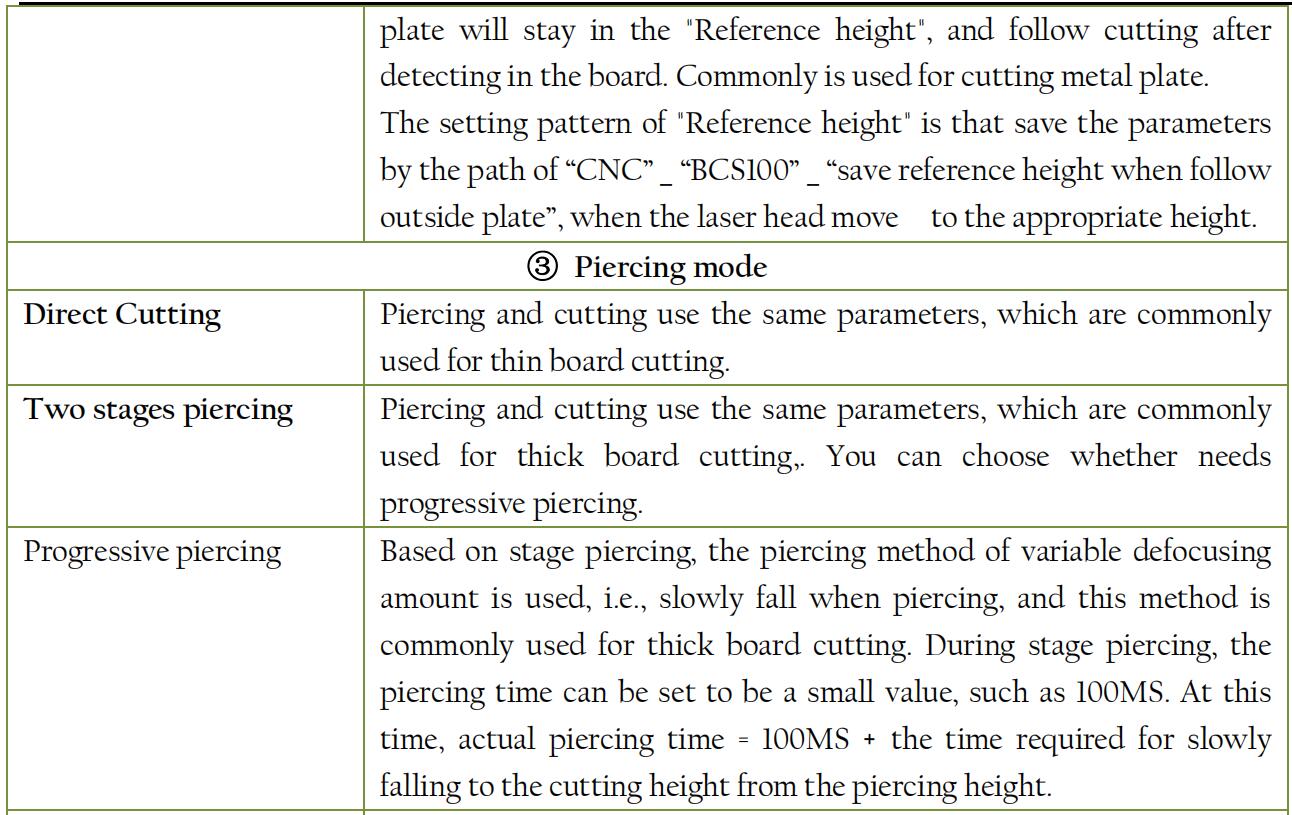


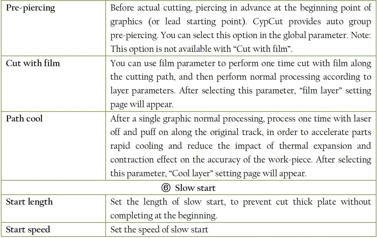
3.11.2 Dynamic power and frequency adjustment
After selecting “![]() ”, the cutting power and frequency will vary with the changes in speed during the cutting process, and the specific changes are determined by the power and frequency curve. You can click “
”, the cutting power and frequency will vary with the changes in speed during the cutting process, and the specific changes are determined by the power and frequency curve. You can click “![]() ”button to edit power and frequency curve.
”button to edit power and frequency curve.
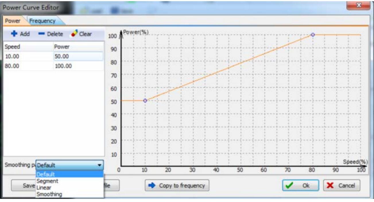
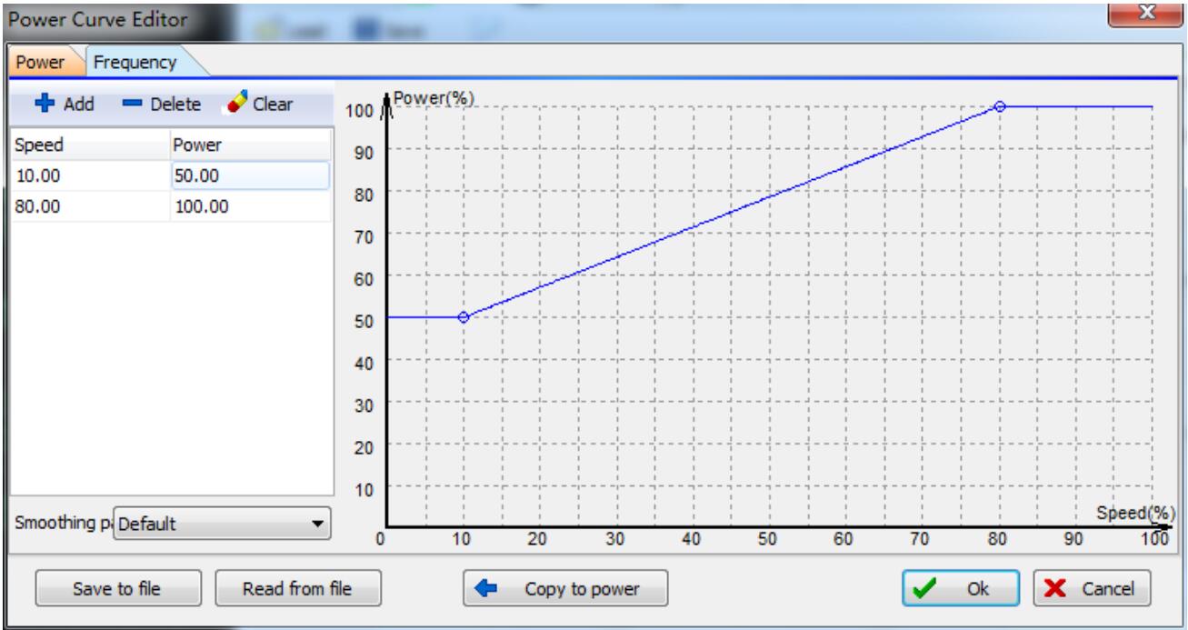
As shown above, the X-coordinate of power / frequency curve represents cutting speed, while the Y-coordinate represents cutting power / frequency, with a unit in percentage. You can add the
appropriate speed corresponding to power point and select the curve smoothing pattern. You can also click “ ![]() ” to copy the power curve as frequency curve. By this table, it can reflect the percentage of actual power/ frequency in cutting power/ frequency when the actual movement reaches the turning and the speed drops to a few percent of target speed. Note: Adjusting frequency in real-time makes sense only after selecting “Dymc Pwr Adj”.
” to copy the power curve as frequency curve. By this table, it can reflect the percentage of actual power/ frequency in cutting power/ frequency when the actual movement reaches the turning and the speed drops to a few percent of target speed. Note: Adjusting frequency in real-time makes sense only after selecting “Dymc Pwr Adj”.
For example, if the laser power is 500W, after setting the cutting speed to be 100mm/s, peak current to be 90% and cutting power to be 80%, when the actual cutting speed drops down to
29mm/s, the power of laser is as follows:
Laser power X Peak current (percentage) X Cutting power (percentage) X Speed following power (percentage) X =500W X 90% X 80% X 79.00%= 284.4W
However, the power cannot be less than a pre-set minimum value, anyhow. Generally, it is set to be 10%, i.e., 500W * 10% = 50W.
If “![]() ” is not selected, the power will remain unchanged in the cutting process. Referring the above example as a reference, the power in the cutting process is as follows: 500W X 90% X 80% = 360W
” is not selected, the power will remain unchanged in the cutting process. Referring the above example as a reference, the power in the cutting process is as follows: 500W X 90% X 80% = 360W
3.11.3 Piercing Ways
CypCut presets three piercing ways, namely direct cutting, two stages piercing and three stages piercing. Two stages piercing and the three stages piercing can be achieved only with the support of
BCS100 height controller. The specific processes of these three piercing ways will be controlled by the preset PLC process. Direct cutting is commonly used in cutting plate; two stages piercing is also known as segment piercing, and achieves the purpose of cutting thicker plates by setting different parameters of piercing and direct cutting. You can choose whether to enable a progressive piercing during segment piercing, which can make piercing process more fully. Three stages piercing is performed before segment piercing. As the same, you can choose whether to enable a progressive piercing during piercing to strengthen piercing effect, usually used for cutting thicker plate.
3.11.4 Pre-piercing
After selecting “![]() ”, it will pierce firstly at all the needed positions when processing this layer. The piercing way will be specified by “
”, it will pierce firstly at all the needed positions when processing this layer. The piercing way will be specified by “ ![]() ” in the layer.You can operate “Direct Cutting” after completing pre-piercing.
” in the layer.You can operate “Direct Cutting” after completing pre-piercing.
Note: You can select “ ![]() ” only after you select “2 stages” or “3 stages” piercing.
” only after you select “2 stages” or “3 stages” piercing.
3.11.5 Material Library file
After editing all the parameters of the layers, you can save them to the material lib for the next use. You can save them to the material lib by clicking the button “ ![]() ” and inputting the file
” and inputting the file
name,. We recommend the user to set the file names by using the material properties as the name, such as 2mm carbon steel.
When you need to use the material library file next time, please click the button “ ![]() ”, and then select the file saved previously. CypCut will prompt you “Whether Covering the Current
”, and then select the file saved previously. CypCut will prompt you “Whether Covering the Current
Parameters”, and the software will import the parameters in material library file automatically when you click “Yes”; if you click “No”, the software will cancel the reading operation.
3.11.6 Layer setting
You can choose lock or display a particular layer according to prompt by clicking drop-down triangle button of “Layer” under “Home” menu. If there are multiple layers when import DXF files,
please click the “DXF Layer Mapping” to see the number of layers and the corresponding graphics. As shown below:

3.12 Sorting and Path Planning
You can find the column shown below in the page “Draw” of the toolbar. It includes all the functions listed in the above figure, furthermore, there are tools for graphical alignment at the top. As
shown below:
As for the rules of group sort, please see the chapter “Group”. If there is no special requirement, we recommend you to select the way of “Grid Sorting”.

3.12.1 Order Preview
You can preview the processing order by dragging the progress bar “Graphical Order Preview” or clicking the button “![]() ”. The figure below demonstrates a screen when previewing the parts.
”. The figure below demonstrates a screen when previewing the parts.

The order preview is fully interactive and it can be more easily controlled than simulation processing. You can also zoom in the position where you would like to observe carefully and preview
forward and backward repeatedly. All the move paths will be shown by clicking the button “ ![]() ” und drop-down triangle button of “View” on the common toolbar, and they will help you to look over the whole processing order.
” und drop-down triangle button of “View” on the common toolbar, and they will help you to look over the whole processing order.
3.12.2 Manual Sorting
If you would like to fine-tune the results of the automatic sort, you can use the manual sorting.Firstly please select the graphics to be adjusted, and then click the buttons in the icon “ ![]() ”.
”.
The functions of the four buttons from left to right are as follows:

Note: no matter how you move the graphics, the order of the graphics can only change within the layers to which they belong. The overall order between the layers can be adjusted in the dialog box
“Layer Parameter Settings”. See the chapter “Layer Parameters”.
Except the manual sort of fine-tuning, you can also perform the manual sort more intuitively through “Manual Sorting Mode”. The system will enter the “Manual Sorting Mode” after you click the
button “ ![]() ” on the left toolbar of the main interface. The move path and the digital display of the graphical order will be opened automatically on the screen. According to your expected order, the processing order of the graphics will be set after you click with the mouse one by one. If click an incorrect position by mistake, you just need to click again from the incorrect position or cancel the operation with the right key. If you just would like to adjust the order between two graphics, you can hold the mouse and draw a line from one graphic to another, and then you can set the order between these two graphics. As shown below.
” on the left toolbar of the main interface. The move path and the digital display of the graphical order will be opened automatically on the screen. According to your expected order, the processing order of the graphics will be set after you click with the mouse one by one. If click an incorrect position by mistake, you just need to click again from the incorrect position or cancel the operation with the right key. If you just would like to adjust the order between two graphics, you can hold the mouse and draw a line from one graphic to another, and then you can set the order between these two graphics. As shown below.

3.12.3 Partition Sorting
After completing sorting the order of one part, if you hope to fix it, you can select the graphics needed to fix the order and then click “Group”. After that, the order between them will maintain
unchanged; besides, the subsequent manual sorting and automatic sorting will not influence the interior of the group. Note: after grouping, all the graphics within the group will be finished by
continuous work from the first to the last, meanwhile, the graphics which are not included in the group will not be processed.
If you just would like to perform automatic sort for part of the graphics without influencing other parts, you can also complete it through grouping. Please select the graphics needed to be sorted
automatically, click “Group”, and then click “Group” with the right key, lastly select “Sort in Group”.

Part4 – Work Control
CypCut is a set of software combining design and work control together. As mentioned above, all the graphics and the parameters can be prepared without the machine tool, the files can be saved after finishing all the design, and then they can be copied to the machine tool for processing.
4.1 Coordinate System
The “Model Coordinate System” used in the graphical design has no relation with the machine, and its zero point is marked by “![]() ” on the screen. However, the coordinate system used in the
” on the screen. However, the coordinate system used in the
processing is related to the operating status of the machine. The correspondence of these two coordinate systems is shown as below.

The positional relation between the graphics and the machine tool breadth will be displayed on the screen after you click the button “preview” on the console.
4.1.1 Mechanical Coordinate System
The mechanical coordinate system is uniquely determined by the machine structure and the machine parameters. At any time all the coordinate systems set through clicking “Go Origin” are
consistent with each other. You can reset the mechanical coordinate system through clicking “Go Origin” in the “CNC” page after completing the initial installation or when the mechanical
coordinate system deviates because of the abnormal reasons.
No matter which kind of mechanical structure is used, the definitions of CypCut for the coordinate systems are always consistent with each other. All the moves are the moves of the laser
head relative to the workpiece. If the laser head is rightward, it is X positive direction; however, if the laser head is backward, it will be Y positive direction. That is to say, the lower left corner of the workpiece (steel plate) is the minimum coordinate, while the upper right corner is the maximum coordinate.
4.1.2 Program Coordinate System
Because the coordinate system of machine tool is fixed, you need to introduce the workpiece coordinate system for convenient use. The direction of each coordinate axis of all the program
coordinate systems in CypCut is fully consistent with the machine coordinate system. Only the zero point of the coordinate system is different, and it is called program zero point. The program
coordinate system is divided into the floating coordinate system and the workpiece coordinate system.

The button at the top of the console can be used to select the program coordinate system, and it can also be used to select “Floating Coordinate System”, nine “Workpiece Coordinate Systems” and
one “External Ucs”.
Usually the floating coordinate system is used for informal processing, and it can be considered that “Where the laser head moves, it will start to work from there”. The zero point of its coordinate
system is automatically set as the current position of the laser head when the users click “Walk”, “Dry Cut” or “Work”.
When selecting the workpiece coordinates 1~9, its zero point will be set manually by the users through “Set the Current Point as the Zero Point”. Once it is set, it will be saved forever until you reset it next time. Thus the workpiece coordinate system is suitable for bulk production, and its location is generally decided by the fixture. It can be maintained that every processing will be
performed in the same position of the machine by using the workpiece coordinate systems 1~9.
Click status bar “![]() “at the bottom. You can choose to “Show Machanical or Program Position. You can also set zero here of the two coordinates. If you select “coordinate
“at the bottom. You can choose to “Show Machanical or Program Position. You can also set zero here of the two coordinates. If you select “coordinate
positioning”, laser head will be positioned to a specified coordinate position.

4.1.3 Searching Zero Point after Exception Occurs
- Case one
If the processing is interrupted only due to the exception of external equipments such as the laser and auxiliary gas, and they do not cause the coordinate system to deviate, you can click directly “Return Zero” to go to the zero point.
- Case Two
If the mechanical coordinate deviates due to suddenly power failure or servo alarm, we recommend the users to perform “Go Origin”, reset the mechanical coordinate system, and then click
“Return Zero” to find the zero point.
4.2 Alarms
CypCut will monitor all the parts during the running of the machine. Once it monitors the alarms, it will display immediately the alarm in red title bar and take measures such as stopping the
motion. Before the software alarms are removed, many operations will be forbidden, and users need to check the machine and operation again after the alarms are canceled. One example of the alarm is as shown below.

Except the title bar, the “Alarm Window” at the lower left corner of the interface can also display the alarm information. After the alarms are removed, the red display of the title bar will disappear,
however, the information in the “Alarm Window” will be retained. You can look over all the history by double clicking “System Window”, so that you can find out the events happened during the
running of the software.
In addition to the alarms, if CypCut detects other operation exceptions, it will display the exceptions in different colors on the “Alarm Window” according to the exception levels, which
include warning, reminding, message and so on. This information will not cause the machine to stop moving, however, it will still suggest you to pay attention to the information shown by the software in time so that you can take the necessary measures as soon as possible.
4.3 Manual Testing
The functions of the manual control on the console are shown in the following figure:

The button with the icon “ ![]() ” will become “
” will become “![]() ” after the corresponding equipment is opened. You can turn on the laser by pressing the button “
” after the corresponding equipment is opened. You can turn on the laser by pressing the button “ ![]() ”, and you can turn off the laser by
”, and you can turn off the laser by
releasing it. You can switch other buttons by pressing them and not conduct any actions by releasing them. Taking button “![]() ” as an example, blowing will start after you press the button, and it will stop after you press the button again. According to the differences of the lasers, the “
” as an example, blowing will start after you press the button, and it will stop after you press the button again. According to the differences of the lasers, the “![]() ” may become “
” may become “![]() ” after pressing the button and this state is read from the laser.
” after pressing the button and this state is read from the laser.
Note: all the button actions need the support of the corresponding parts on the machine. If the machine is not equipped with these parts, or the platform parameter configuration is incorrect, some
buttons may become invalid.
The current position of the machine tool can be recorded by clicking “![]() ”, and the machine can return to the previously recorded position by clicking “
”, and the machine can return to the previously recorded position by clicking “ ![]() ” if required later.
” if required later.
Six positions can be recorded in total and they will be selected through “![]() ”.
”.
4.4 Soft Limit Protection
In order to protect the machine, CypCut is installed internally with the soft limit protection, which can be turned on and off through the option “” on the console. It is enabled by default.
After the soft limit protection is enabled, if the software detects that the motion may exceed the travel range, it will prompt “Motion is Out of the Range”, and will not issue any motion commands to avoid the possible hits. At this moment please check the positions of the graphics and the machine to ensure that there is no mistake before operation.
Apart from this, the software will also monitor the machine coordinates in real time during the motions of the machine. Once they are beyond the soft limits, the software will alarm at once and then stop all the motions.
Note: the soft limit protection depends on the machine coordinate system. If the coordinate system is not correct, the protection will also be incorrect. Thus, after the operations such as
abnormal close of the system and modification of the machine parameters, users need to build the correct machine coordinate system through the operation “Go Origin”.
4.5 Frame
The laser head will dry cut a rectangle along the frame of the graphic to be processed by clicking the button “![]() ” on the console, so that you can determine the approximate size and
” on the console, so that you can determine the approximate size and
position for processing the boards. The speed of walk can be set in the “Layer Parameter Setting” – “Global Parameters” – “Walk Around Parameters”.
Note: If you operate “Edge Seek” before framing, the software will record the results. The laser head will move along the inclined rectangle during framing, that is to say, move along the actual frame which is corrected by the “Edge Seek”. See the Chapter “Edge Seek” for the details.
4.6 Processing and Dry Cut
You can start processing by clicking the button “ ![]() ” on the console. During the processing the monitoring screen will be displayed as below. It includes the information such as the
” on the console. During the processing the monitoring screen will be displayed as below. It includes the information such as the
coordinates, the speed, work time, follow height and so on.

When displaying the screen above, it cannot be switched to other pages of the toolbar, in order to prevent from modifying the graphics during the processing. However, the menu “File” can still be
used. If you need to modify the parameters during the processing, please pause firstly, and then click the button “Layer” on the right toolbar of the interface.
You can perform the operation of dry cut by clicking the button “ ![]() ” on the console. The difference between dry cut and the actual processing lies in that dry cut can select whether to
” on the console. The difference between dry cut and the actual processing lies in that dry cut can select whether to
follow without the need for turning on laser or gas. However, all the running tracks, including the move, speed, process of acceleration and deceleration of “Prepiercing”, are exactly same to the actual processing. You can also perform the same operations of pause, continue, forward and backward; besides, the breakpoint memory after stopping is identical to that of the actual processing;
furthermore, you can modify the parameters after pausing, and then continue the operation of dry cut. Thus dry cut can be used for the comprehensive inspection and simulation of the whole processing without cutting.
If you would like to open “Follow” during the dry cut, please select “ ![]() ” in “Layer Parameter Settings” – “Global Parameters” – “Follower Param”. In the default condition it will not open “Follow” during the dry cut. By default, it will return to the zero point automatically after completing the processing. If you would like to return to other position after the processing, please select the needed position on the console. The supported positions include zero point, start point, end point, origin point and record point. Cancelling “
” in “Layer Parameter Settings” – “Global Parameters” – “Follower Param”. In the default condition it will not open “Follow” during the dry cut. By default, it will return to the zero point automatically after completing the processing. If you would like to return to other position after the processing, please select the needed position on the console. The supported positions include zero point, start point, end point, origin point and record point. Cancelling “ ![]() ” is equal to returning to the “End Point”, that is to say, the laser will not move after the processing. If you use the “Floating Coordinate System”, we recommend you to return to the zero point after the processing. If you hope to return to record point after the processing, please select “Record&1” and confirm it.
” is equal to returning to the “End Point”, that is to say, the laser will not move after the processing. If you use the “Floating Coordinate System”, we recommend you to return to the zero point after the processing. If you hope to return to record point after the processing, please select “Record&1” and confirm it.

Every time when the processing is finished, the process count on the console will add 1, and when it reaches the preset times, a dialog box will
be popped to prompt so that you can control the production. You can open “Auto Pause” interface to control piece management and auto pause
by clicking the button “![]() ”. If you need loop work, please click the button “
”. If you need loop work, please click the button “![]() ” to set corresponding parameters.
” to set corresponding parameters.
4.7 Stop, Pause and Resume
If you need to stop the processing, please click the button “![]() ” on the toolbar during processing or the button “
” on the toolbar during processing or the button “![]() ” on the console. After stopping, the machine will return to
” on the console. After stopping, the machine will return to
the zero point. If you do not hope to go back to the zero point, please cancel the selection of option “![]() ” on the console.
” on the console.
If you pause the processing, please click the button “![]() ” on the toolbar during processing or the button “
” on the toolbar during processing or the button “![]() ” on the console. Then the processing will resume from where you pause.
” on the console. Then the processing will resume from where you pause.
If you need to continue to work, please click the button “![]() ” on the toolbar during processing or the button “
” on the toolbar during processing or the button “![]() ” on the console. If the parameters are modified during the pause, the button “Continue” will be marked with “*”, which indicates that the system needs to rebuild the processing commands. According to the size of the files to be processed, you may need to wait a while if you click the button “Continue” at this moment.
” on the console. If the parameters are modified during the pause, the button “Continue” will be marked with “*”, which indicates that the system needs to rebuild the processing commands. According to the size of the files to be processed, you may need to wait a while if you click the button “Continue” at this moment.
During the pause, you click the button “ ![]() ” or the button “
” or the button “ ![]() ” so that the machine can move backward or forward along the processing track. The distance and the speed of every motion can be set through the button “ ” on the console.
” so that the machine can move backward or forward along the processing track. The distance and the speed of every motion can be set through the button “ ” on the console.
4.8 Breakpoint Memory
If the processing stops or suspends due to accidents, the software will keep breakpoint memory. As long as the graphics or the parameters are not modified, you can click “ ![]() ”, and then the software will automatically locate to the position where it stopped last time; If you click “
”, and then the software will automatically locate to the position where it stopped last time; If you click “![]() ”, the software will continue to start processing from the position where it stopped last time.
”, the software will continue to start processing from the position where it stopped last time.
If you change the corresponding parameters after stopping, the “*” will appear behind “Start” on the console. When “![]() ” appears, functions of “
” appears, functions of “ ![]() ” and “
” and “ ![]() ” will no
” will no
longer be used.
4.9 Processing from Any Location
CypCut support the function to start processing from any specified position. Users can right-click the location where you want to start, and then select “Processing from Here”. As shown in
the right figure.
For safety reasons, the software will pop-up a dialog box and requires reconfirmation after selecting “Processing from Here (F)”. After
confirmation, the laser head will move to the location you specify and then start processing from there, and the tracks in front of the specified location will not be processed.
If you want to first position it to the specified location but do not start processing, please select “Positioning Here”, so that the system will move to the specified location and then go into the suspended state.
You can right-click the place for many times and select “Positioning Here”, until the operation is confirmed. You can also conduct positioning in a more precise manner through “![]() ” and “
” and “![]() ”.
”.

4.10 Global Parameters
Some movement control parameters are provided in the tab “Global Parameters” of dialog box “Layer Parameter Adjustment” for adjustment. The adjustment of these parameters will influence the smoothness of mechanical running as well as processing effect and efficiency.Some parameters of tab “Global Parameters” are list in the table below.


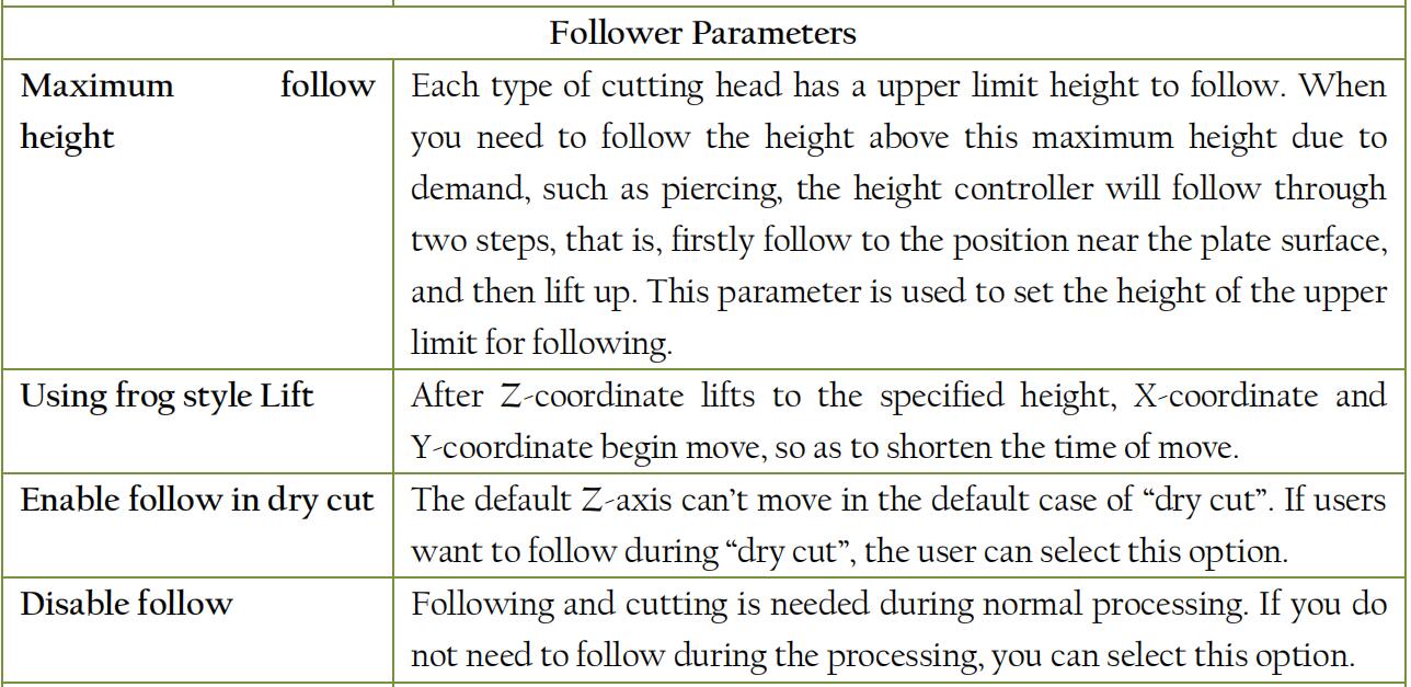

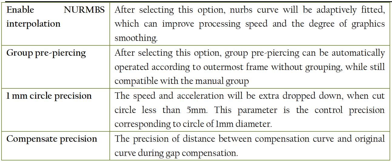
Part5 – NC auxiliary function
5.1 Analog Processing
After all the sorting of patterns is completed, you can simulate the processing of entire document through simulation. This process can be carried out of the machine. Simulations can see not only the order among the graphics, but also the process within graphics.
Click ” ![]() ” button to start simulation, and the toolbar will automatically jump to the “CNC” page. You can adjust the analog processing speed in the first column of “CNC” page, as shown
” button to start simulation, and the toolbar will automatically jump to the “CNC” page. You can adjust the analog processing speed in the first column of “CNC” page, as shown
below.

5.2 Edge seek
CypCut software supports “BCS100 edge seek”, “Infared edge seek” and “Manually edge seeking”.
By clicking “Edge seek” drop-down triangle button, you can choose the most appropriate way to seek
edge, in order to determine the placement of the plate. Seek results will be displayed in the top right
of the drawing area, as shown below:
5.2.1 BCS100 edge seek
By clicking “![]() ” button under the “CNC” page or clicking “BCS100 edge seek”, you can enter the edge interface.
” button under the “CNC” page or clicking “BCS100 edge seek”, you can enter the edge interface.

“BCS100 edge seek” needs to set some parameters. Edge seeking speed has effect on the precision of edge seeking, recommending setting value is 200mm / s. The plate width is length of plate in the machine X axis direction. The plate length is length of plate in the machine Y axis direction. Correction value is used for correcting seek result, with a positive number indicating the laser head is shifted inside the plate and negative number indicating the laser head is shifted outside the plate.
Rising height is the height that the cutting head lifts during edge seeking. After unlocking advanced parameters, you can set the following parameters.

After selecting “Avoid the impact of edge”, you can set “rack space”, “prong space”, “rack direction” and “rack pattern” to avoid rack impact on edge seeking. When you enable this function,
you must firstly mark prong coordinates. “Rack space” is the space between adjacent racks; “prong space” is the distance between adjacent prongs; “rack direction” is the relative relationship between the rack installing position and the machine; “rack pattern” is to select dislocation installation or alignment installation; “No prong” is the setting when the rack is neither dislocation installation nor alignment installation.

You can jog the cutting head to the appropriate starting position through small console on the right. Please move the cutting head inside plate as the starting position of edge seeking, and then
select the operation under edge seeking testing that you want to perform. If select “Edge seek before start”, the software will perform “BCS100 edge seek” during moving or before starting to process based on the stopping position of graphics.
Note: Please return origin to correct the machine coordinate system and confirm cutting head can properly follow before you operate edge seeking. The inclination angle of steel should not exceed
10 degrees.
5.2.2 Infared Edge seeking
At present, the software uses “Infared Edge seeking” function required matching with Omron E3Z-L61 model switch.
Before the first edge seek, the offset value of the photoelectric switch and laser Center should be determined and set in advanced parameters. Before the actual edge seek, please make sure to move the cutting head to the nearby stopping point (among upper left, lower left, upper right, lower right) as the starting position of edge seek.

“Infared Edge seeking” needs to set some parameters. Coarse positioning speed is the speed of coarse positioning during edge seek, and recommended value is 100mm/s. Fine positioning speed is
the speed of fine positioning during edge seek, which will affect the accuracy of edge seek, recommending setting value as 10mm / s without exceeding 30mm / s. The smaller the fine positioning
speed is, the longer the time of edge seek is and the higher positioning accuracy is. Plate size and correction value is similar to “BCS100 edge seek”.
The deviation between the photoelectric switch and the laser head can be corrected by setting advanced parameters and filtering rack interference.
You can set the following parameters: “Offset value” is the deviation between photoelectric switch and the laser head position. After setting the “deviation between photoelectric switch and thelaser head”, the software will automatically set this parameter without manually modifying. “Rack space” can filter out the interference of rack on Infared Edge seeking. It is recommended to set the
value consistent with the actual rack space. “Set edge height” applies to the case of the photoelectric switch fixed in the cutting head. Users can adjust the position of the photoelectric switch thorough jogging height controller. You can read this height through “Set as the current height”.
When the edge seek is opened each time, height controller will move to this height. In addition, move to this height by “positioning”. “Fixed height edge seek” applies to the case of the photoelectric switch without being installed in the cutting head.
Note: Plate tilt angle should not exceed 40 degrees.
5.3 PLC Process
Click the “![]() ” button under the “CNC” page, you can customize the PLC process and execute them.
” button under the “CNC” page, you can customize the PLC process and execute them.
Note: Improper modification may lead to serious consequences! If necessary, please contact our technical staff.
5.4 Go origin
5.4.1 Return to origin
You can click the “![]() ” under the “CNC” page or select “All axis” under its drop-down menu to make laser head return to mechanical origin and reset the machine coordinate system. The details
” under the “CNC” page or select “All axis” under its drop-down menu to make laser head return to mechanical origin and reset the machine coordinate system. The details
refer to “coordinate” part. You can also select “X only” or “Y only” under drop-down menu to make a single axis separately return to origin.
5.4.2 Gantry synchronism
During using a dual-drive gantry machine, the beams of machine may become crooked occurring after a period of operation due to various reasons, such as the unparallel installation of two Y axes,
friction and load, which will affect machining accuracy. Gantry synchronism function judge and automatically adjust the vertical position of the beam by recording and monitoring Z signal of Y1 and Y2 axes when go origin.

Click the drop-down triangle of “Go origin” on the “CNC” Page and select “Gantry initialization”, as shown on the right:
Select “Execute gantry synchronism when return to origin” after completing Gantry initialization”, and enter the password. Related compensation information will be displayed in system window of the software.
Note: Make sure re- execute “Gantry initialization” after adjusting machine. Specific steps and precautions, please, refer to Appendix.
5.5 Optical adjustment
During the specific processing, if you need to locate the cutting head to a specific point, you can click “![]() ” button, and input a specific coordinate you want to locate, as shown at right.
” button, and input a specific coordinate you want to locate, as shown at right.

You can also appropriately set the laser interferometer on the adjustment interface of optical path to test error between the movement position given by the software and the actual mechanical,
thereby performing mechanical error compensation, also known as pitch compensation.
5.6 Diagnosis
During processing, click the ” ![]() ” button, you can observe the state information of each cutting part, in order to determine whether there is a problem in the process.
” button, you can observe the state information of each cutting part, in order to determine whether there is a problem in the process.
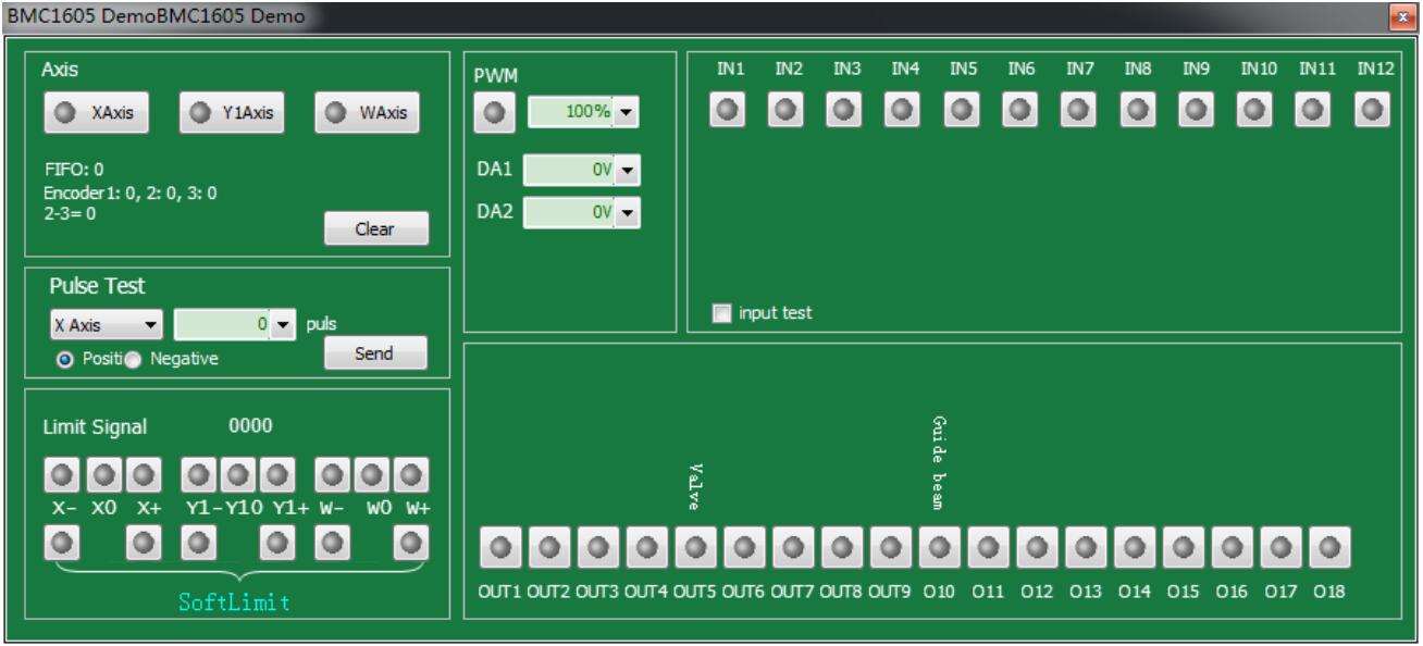
Motion axis shows each axis signal and the corresponding encoder feedback value; Pulse test is used to send fixed pulse to single axis, in order to test the accuracy of pulse equivalent; Limit signal is used for displaying whether the cutting head is hit limit; PWM is used to show the situation of laser switch; The valid situation of 12 inputs and 18 outputs are also shown.
5.7 BCS100
This function must be used compatible with our height controller BCS100. By clicking ” ![]() “, you can operate a series of actions in the software, such as Return to origin, Follow to, Absolute
“, you can operate a series of actions in the software, such as Return to origin, Follow to, Absolute
positioning and one key calibration, to control BCS100. And you can also operate via BCS100 monitoring interface without operating on the entity, which is more convenient and quick.
5.8 QCW
QCW is a mode of laser operation. CW and QCW is two modes d of laser. CW is continuous light, and QCW is pulse laser. By clicking ” ![]() ” button, you can set the appropriate optical
” button, you can set the appropriate optical
parameters.
5.9 Deviation measurement
When click ” ![]() “, the cutting head will move along the graphics to be processed. After the cutting head finishes move, a blue dotted line will appear to show the trajectory of the servo motor
“, the cutting head will move along the graphics to be processed. After the cutting head finishes move, a blue dotted line will appear to show the trajectory of the servo motor
feedback. You can adjust process parameters required for the actual cutting according to this trajectory.\
—End
Краткое описание загружаемого файла
 CAD-CAM ПО для подготовки чертежей, схем раскладки и управления процессом лазерной резки.
Локализованная версия документации к программе CypCut на русском языке в формате PDF.
Предназначена для самостоятельного изучения функций и возможностей программы при подготовке чертежей, схем раскладки и осуществлении процесса управления совместимым оборудованием для лазерной резки.
Система управления CypCut представляет собой систему программного обеспечения, предназначенного для лазерной резки, которая включает в себя не только управление процессом лазерной резки, но и управление слоями, обработку изображений, настройку процесса резки, планировании траектории обработки, моделирование процесса резки.
Программное обеспечение CypCut может выполнять процесс управления только при использовании ключа и платы управления. При отсутствии ключа система CypCut переходит в режим DEMO, что позволяет получить доступ ко всем функциям системы, кроме процесса управления резкой. Это позволяет установить программное обеспечение CypCut на отдельном компьютере для разработки программы обработки.
Данное руководство по эксплуатации относится только к основной программе системы ПО CypCut. Для получения информации по другим инструментам из пакета ПО CypCut обратитесь к соответствующим руководствам по эксплуатации или свяжитесь с производителем.
Данное руководство основано на версии 6.3.646.6 CypCut. В связи с обновлением программы возможны различия между функционалом программы и описанием, приведенным в данном руководстве по эксплуатации.