-
Contents
-
Table of Contents
-
Troubleshooting
-
Bookmarks
Quick Links
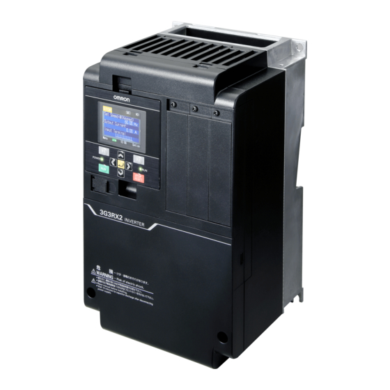
Inverter
RX2 Series
DriveProgramming
User’s Manual
3G3RX2 Series
CX-Drive
I622-E1-01
Related Manuals for Omron RX2 Series
Summary of Contents for Omron RX2 Series
-
Page 1
Inverter RX2 Series DriveProgramming User’s Manual 3G3RX2 Series CX-Drive I622-E1-01… -
Page 2
OMRON. No patent liability is assumed with respect to the use of the information contained herein. Moreover, because OMRON is constantly striving to improve its high-quality products, the information contained in this manual is subject to change without notice. -
Page 3: Introduction
Introduction Introduction Thank you for purchasing the Inverter/Servo support tool CX-Drive and 3G3RX2 Series Inverter. This manual describes the specifications and operating methods of the DriveProgramming for the inverter. When you use this product, refer to the High-function General-purpose Inverter 3G3RX2 Series User’s Manual (I620), besides the CX-Drive Operation Manual (W453).
-
Page 4: Manual Configuration
Manual Configuration Manual Configuration This manual is compiled section by section for user’s convenience as follows. Section Overview This section describes an overview and the system configuration Section 1 Overview of the DriveProgramming. Section 2 Specifications This section describes the specifications of the DriveProgramming. Operation Procedure for This section describes the operation procedure of the Section 3…
-
Page 5: Manual Structure
Manual Structure Manual Structure Page Structure The following page structure and symbol icons are used in this user’s manual. Level 1 heading 8 Errors and Remedies Level 2 heading Troubleshooting This section describes the program operation at the time of error occurrence, the error codes that are specific to the DriveProgramming, and the remedies for them.
-
Page 6
Manual Structure Special Information Special information in this user’s manual is classified as follows: Precautions for Safe Use Precautions on what to do and what not to do to ensure safe usage of the product. Precautions for Correct Use Precautions on what to do and what not to do to ensure proper operation and performance. Additional Information Additional information to read as required. -
Page 7: Sections In This Manual
Sections in this Manual Sections in this Manual Overview Specifications Operation Procedure for DriveProgramming DriveProgramming Editor DriveProgramming User Variables DriveProgramming Commands Precautions for Use of Parameters for DriveProgramming Errors and Remedies DriveProgramming User’s Manual (I622-E1)
-
Page 8: Table Of Contents
CONTENTS CONTENTS Introduction ………………….1 Manual Configuration ………………..2 Manual Structure …………………. 3 Sections in this Manual ………………. 5 CONTENTS…………………… 6 Terms and Conditions Agreement …………….9 Safety Precautions ………………..10 Precautions for Safe Use ………………13 Regulations and Standards ………………. 14 Related Manuals …………………
-
Page 9: Contents
CONTENTS Section 4 DriveProgramming Editor Starting DriveProgramming Editor ………………4-2 Parts of DriveProgramming Editor………………4-6 4-2-1 DriveProgramming Editor ………………….4-6 4-2-2 Toolbar ……………………….4-6 4-2-3 DriveProgramming Area ………………….4-9 4-2-4 Toolbox Window……………………4-13 4-2-5 Block Parameters Window………………….4-14 4-2-6 Properties Window……………………4-15 4-2-7 Error List Tab in Output Window ………………..
-
Page 10
CONTENTS Section 7 Precautions for Use of Parameters for DriveProgram- ming Inverter Parameters Affected by Setting Order …………..7-2 Parameters Affected by Rated Current [%] …………….. 7-6 Parameters Affected by PID Enabled/Disabled …………..7-8 Section 8 Errors and Remedies Troubleshooting ……………………8-2 8-1-1 DriveProgramming Operation on Error ……………… -
Page 11: Terms And Conditions Agreement
OMRON will replace defective media without charge. If OMRON is unable to replace defective media or correct the Software, the liability of OMRON and the User’s remedy shall be limited to the refund of the license fee paid to OMRON for the Software.
-
Page 12: Safety Precautions
Safety Precautions Safety Precautions Indications and Meanings of Safety Information In this manual, the following precautions and signal words are used to provide information to ensure the safe use of the DriveProgramming. The information provided here is vital to safety. Strictly observe the precautions provided. Meanings of Signal Words Indicates an imminently hazardous situation which, if not avoided, is DANGER…
-
Page 13
Safety Precautions WARNING Turn off the power supply and implement wiring correctly. Not doing so may result in a serious injury due to an electric shock. Wiring work must be carried out only by qualified personnel. Not doing so may result in a serious injury due to an electric shock. Do not change wiring and slide switches (SW1 to SW6), put on or take off Operator and optional devices, replace cooling fans while the input power is being supplied. -
Page 14
Safety Precautions Caution Do not connect resistors to the terminals (PD/+1, P/+, N/-) directly. Doing so might result in a small-scale fire, heat generation, or damage to the unit. Install a stop motion device to ensure safety. Not doing so might result in a minor injury. (A holding brake is not a stop motion device designed to ensure safety.) Be sure to use a specified type of braking resistor/regenerative braking unit. -
Page 15: Precautions For Safe Use
Precautions for Safe Use Precautions for Safe Use Operation and Adjustment • If the clock command is used in DriveProgramming, an unexpected operation may occur due to weak battery. Take measures such as detecting a weak battery by [E042]RTC Error and stopping the inverter or programs.
-
Page 16: Regulations And Standards
Regulations and Standards Regulations and Standards To export (or provide to nonresident aliens) any part of this product that falls under the category of goods (or technologies) for which an export certificate or license is mandatory according to the Foreign Exchange and Foreign Trade Control Law of Japan, an export certificate or license (or service transac- tion approval) according to this law is required.
-
Page 17: Related Manuals
Related Manuals Related Manuals You need information on the devices connected for operating this product. Please see the manuals below for related product information. Name Catalog number CX-Drive Operation Manual W453 High-function General-purpose Inverter 3G3RX2 Series User’s Manual I620 Additional Information For the inverter operation, refer to the High-function General-purpose Inverter 3G3RX2 Series User’s Manual (I620).
-
Page 18: Revision History
Revision History Revision History The manual revision code is a number appended to the end of the catalog number found on the front and back covers. Example I622-E1-01 Cat.No. Revision code Revision code Revision date Revised Content January 2019 Original production DriveProgramming User’s Manual (I622-E1)
-
Page 19: Overview
Overview This section describes an overview and the system configuration of the DriveProgramming. 1-1 Overview of DriveProgramming ……..1-2 1-2 Preparation and System Configuration .
-
Page 20: Overview Of Driveprogramming
1 Overview Overview of DriveProgramming The DriveProgramming is the simple sequence function built into the inverter. To create sequence programs and check their status, you use the Inverter/Servo supporting tool, CX-Drive. Transfer (download) the created programs to the 3G3RX2 Series Inverter so that the stand-alone inverter can perform simple sequence control.
-
Page 21
1 Overview Monitoring software CX-Drive Ver. 3.0 or higher *1 (DriveProgramming) 3G3RX2 Series Connect directly Programming Transmission Creation, editing and saving of user programs Upload Compilation Download User Programs Debugging support Program execution Monitor Parameter changed *1. Ver 3.0 or higher: Version supported for 3G3RX2 1 — 3 DriveProgramming User’s Manual (I622-E1) -
Page 22: Preparation And System Configuration
1 Overview Preparation and System Configuration You must prepare the following items to create user programs with functions of the DriveProgramming in CX-Drive and execute the programs in the 3G3RX2 Series Inverter. • 3G3RX2 Series Inverter • Windows personal computer (As for the supported OS (operation system), refer to CX-One User’s Manual (W463).
-
Page 23: Specifications
Specifications This section describes the specifications of the DriveProgramming. 2-1 Specifications ……….2-2 2 — 1 DriveProgramming User’s Manual (I622-E1)
-
Page 24
2 Specifications Specifications The following table shows the specifications related to the DriveProgramming. Item Specifications Program specifica- Programming lan- Flowchart and text language method tions guage Input device Windows personal computer (As for the supported OS (operation system), refer to CX-One User’s Manual (W463). -
Page 25
2 Specifications Item Specifications Function variable User parameter vari- U(00) to U(63)/64 points able Internal user variable UL(00) to UL(15)/16 points Frequency reference SET-Freq variable Acceleration time vari- ACCEL able Deceleration time vari- DECEL able Inverter monitor vari- The monitor functions for the inverter are available as variables. able FM, Iout, Dir, PID-FB, F-CNV, Tmon, Vout, Power, RUN-Time, ON-Time, PlsCnt, POS, STATUS, DCV, ERR-CNT, ERR(1) to ERR(10) -
Page 26
2 Specifications 2 — 4 DriveProgramming User’s Manual (I622-E1) -
Page 27: Operation Procedure For Driveprogramming
Operation Procedure for DriveProgramming This section describes the operation procedure of the DriveProgaramming, related parameters, and program structures. 3-1 Operation Procedure ……… . . 3-2 3-2 Parameters Related to DriveProgramming .
-
Page 28: Operation Procedure
3 Operation Procedure for DriveProgramming Operation Procedure The following figure shows the flow of procedure from programming to executing programs with the DriveProgramming. Item Reference Programming P. 3-3 Compiling Programs P. 3-3 Downloading Programs P. 3-4 Selecting Driveprogramming Functions P. 3-4 Starting Programs P.
-
Page 29
3 Operation Procedure for DriveProgramming Programming You can create user programs in the flowchart method or the text language method. It is also possible to select between two methods for each task or subroutine. Use the DriveProgramming Editor in CX-Drive to input user programs. DriveProgramming Editor consists of the DriveProgramming area, Toolbox window, Block Parameter window, Properties window, and Output window. -
Page 30
3 Operation Procedure for DriveProgramming Downloading Programs Download compiled programs to the inverter and save them in the EEPROM of the inverter. You can start programs saved in the EEPROM after turning on the power supply, without using the tool (CX-Drive). -
Page 31: Parameters Related To Driveprogramming
3 Operation Procedure for DriveProgramming Parameters Related to DriveProgramming This section describes the inverter parameters that are related to the DriveProgramming. Initializing Programs To initialize the DriveProgramming program downloaded to the inverter, select 04 (Trip history + param- eters + DriveProgramming) for the Initialize Mode selection (Ub-01), and execute initialization by Initial- ize Enable (Ub-05).
-
Page 32
3 Operation Procedure for DriveProgramming Setting Inverter I/O Functions In the DriveProgramming, you can use the inverter’s I/O functions (I/O terminal and analog I/O) as the I/O functions of the program. To use the I/O functions, it is necessary to set each I/O function according to the purpose. This section describes how to set I/O functions for the DriveProgramming. -
Page 33
3 Operation Procedure for DriveProgramming Monitor Function of DriveProgramming The following functions are provided to monitor the status of the DriveProgramming. Parameter Function name Data Description db-01 Program download monitor 00: Without a program 00: (Program is not downloaded.) 01: With a program 01: (Program is downloaded.) db-02 Program No. -
Page 34
3 Operation Procedure for DriveProgramming User Parameters of DriveProgramming For user parameters of DriveProgramming, 64 unsigned 1-word variables and 16 signed 2-word vari- ables are provided. Use these parameters for various purposes such as program initial data setting, parameter for adjust- ment, and saving calculation results. -
Page 35
3 Operation Procedure for DriveProgramming Parameter Function name Data Description UE-55 EzSQ user parameter U(45) 0 to 65535 UE-56 EzSQ user parameter U(46) 0 to 65535 • These user parameters corresponds to the function variables U(00) to U(63). UE-57 EzSQ user parameter U(47) 0 to 65535 UE-58 EzSQ user parameter U(48) -
Page 36: Program Structure
3 Operation Procedure for DriveProgramming Program Structure In the DriveProgramming for 3G3RX2 Series Inverter, you can create a maximum of five tasks. The created tasks are processed in parallel. By dividing one application into several processes and allocating them to multiple tasks, you can adjust execution condition, execution order, etc.
-
Page 37
3 Operation Procedure for DriveProgramming • As shown in Task 3, if the “wait” command is executed, the task will be repeatedly executed until a certain condition is met. • As shown in Task 4, if you create a loop by using the “goto” command, the task process will be con- tinuously repeated. -
Page 38: Driveprogramming Start/Stop And Task Operation
3 Operation Procedure for DriveProgramming 3-3-4 DriveProgramming Start/Stop and Task Operation You set the start/stop method of the DriveProgramming programs in the EzSQ function enable (UE-02). Start • When the EzSQ function enable (UE-02) is set to 01 ([PRG] terminal), The program starts when the input terminal set to PRG is turned ON.
-
Page 39
3 Operation Procedure for DriveProgramming • Turn ON the power supply for the inverter again and return the value of UE-02 to that saved in the EEPROM. • Do not perform the following EEPROM saving operations before you turn ON the power sup- ply for the inverter. -
Page 40: Driveprogramming Restart
3 Operation Procedure for DriveProgramming 3-3-5 DriveProgramming Restart You can restart the stopped program by performing the following operations. When the program is restarted, all tasks are started simultaneously from the beginning. • When the DriveProgramming Function Selection (UE-02) is set to 01 ([PRG] terminal): a reset input via the control circuit terminal while the PRG terminal is ON, or turning ON the PRG terminal again.
-
Page 41: Task Operation On Trip
3 Operation Procedure for DriveProgramming 3-3-6 Task Operation on Trip Basically, even if the inverter detects a trip during the DriveProgramming operation, the operation is continued. However, if any of E043 to E045 trips related to the DriveProgramming is detected, the oper- ation is stopped.
-
Page 42
3 Operation Procedure for DriveProgramming 3 — 16 DriveProgramming User’s Manual (I622-E1) -
Page 43
DriveProgramming Editor This section describes how to start the DriveProgramming Editor, saving and loading data, and details on parts of the Editor. 4-1 Starting DriveProgramming Editor ……. . 4-2 4-2 Parts of DriveProgramming Editor . -
Page 44: Driveprogramming Editor
• A password is required when you start the DriveProgramming Editor in the CX-Drive for the first time. Please contact your OMRON representative. CX-Drive and DriveProgramming Editor Screen Layout The DriveProgramming Editor is included as one of the functions of the support tool for the Inverter/Ser- vomotor, CX-Drive.
-
Page 45
Use the following method to start the CX-Drive: from the Windows [Start] Menu, select [All Programs] — [OMRON] — [CX-One] — [CX-Drive]. Click the CX-Drive icon in the CX-Drive folder. After the CX-Drive is started, select [File] from the CX-Drive Menu and click [New] to create a new CX-Drive file. -
Page 46
4 DriveProgramming Editor In the [New Drive] dialog box, you set the connection type for the CX-Drive and the inverter. Under the [Connection Type], select [Direct] and click the [Settings] button to the right. On the [Driver] tab page, set the [Port Selection] to the port name of the computer on which the CX-Drive is installed. -
Page 47
4 DriveProgramming Editor Starting DriveProgramming Editor There are three ways to display the DriveProgramming Editor: • Double click the [DriveProgramming] in the workspace. • Click button on the CX-Drive toolbar. • From the [Drive] Menu, select [Program] — [Program Editor]. Precautions for Correct Use To start the DriveProgramming Editor for the first time after you started the CX-Drive, a pass- word is required. -
Page 48: Parts Of Driveprogramming Editor
4 DriveProgramming Editor Parts of DriveProgramming Editor This section provides the detailed information on each function of the Editor and windows related to the DriveProgramming in the CX-Drive. 4-2-1 DriveProgramming Editor The DriveProgramming Editor is the main widow for the DriveProgramming function. Toolbar DriveProgramming area This window consists of the toolbar in which common commands are included and the DriveProgramming…
-
Page 49
4 DriveProgramming Editor Command Icon Description Transfer to Drive Compiles the program and, if there are no errors, transfers (downloads) it to the drive (inverter). Transfer from Drive Transfers (uploads) the program from the drive (inverter) to the DriveProgramming Editor. Compile Compiles the program in the DriveProgramming area. -
Page 50
4 DriveProgramming Editor Command Icon Description Vertical Align Bottom Aligns vertically the bottoms of the currently selected blocks Orientation Selects an orientation for connecting the blocks Auto-arrange Arranges the blocks of the flowchart automatically in the cur- rently selected orientation. Show Contacts Switches display/hide of the contacts of the blocks Show… -
Page 51: Driveprogramming Area
4 DriveProgramming Editor Command Icon Description Convert Flowchart to Text Converts current flowchart task/subroutine to text. Convert whole program to Converts whole program to text. Text Shortcut keys You can use the following keyboard shortcuts in the DriveProgramming area. Shortcut Description Ctrl + X…
-
Page 52
4 DriveProgramming Editor Flowchart Program In the flowchart program method, a unit of display is called «Block». You create a program by placing more than one block in the area and setting interaction between them. In a flowchart program, when a program is compiled successfully, an icon with a white arrow in a green circle highlights the starting point of each flowchart task. -
Page 53
4 DriveProgramming Editor If you right-click on a flowchart block, a popup menu with more options will appear. The following table shows the menu commands available in the flowchart program. Command Description [Bring To Front] Places the selected block graphically in front of other blocks. [Send To Back] Places the selected block graphically in back of other blocks. -
Page 54
4 DriveProgramming Editor Text Program In the text program method, you create a program by using text language. For text programs that were not compiled successfully, the program errors will be displayed in the Out- put window. The statement with errors will be highlighted with a red line. Right-click the selected text to display a popup menu. -
Page 55: Toolbox Window
4 DriveProgramming Editor 4-2-4 Toolbox Window The Toolbox window allows you to add blocks to the DriveProgramming area by drag and drop. It dis- plays the blocks supported for a particular command, organized in categories. The Toolbox is displayed when the DriveProgramming Editor is started. You can also show or hide it by clicking [DriveProgramming] — [Toolbox] in the [View] Menu.
-
Page 56: Block Parameters Window
4 DriveProgramming Editor 4-2-5 Block Parameters Window The Block Parameters window allows you to edit DriveProgramming user parameters which act as vari- ables of the program. The displayed parameters are organized in categories. The Block Parameters is displayed when the DriveProgramming Editor is started. You can also show or hide it by clicking [DriveProgramming] — [Block Parameters] in the [View] Menu.
-
Page 57: Properties Window
4 DriveProgramming Editor 4-2-6 Properties Window The Properties window allows you to edit the properties of the block which is currently selected in the flowchart program. The Properties is displayed when the DriveProgramming Editor is started. You can also show or hide it by clicking [DriveProgramming] — [Properties] in the [View] Menu.
-
Page 58: Error List Tab In Output Window
4 DriveProgramming Editor 4-2-7 Error List Tab in Output Window The list of errors related to the DriveProgramming is displayed when you click the Error List tab in the Output window. The error list shows the compilation errors and warnings of the program currently created with the DriveProgramming Editor after it is compiled.
-
Page 59: Adding, Deleting And Renaming Tasks
4 DriveProgramming Editor Adding, Deleting and Renaming Tasks The DriveProgramming Editor will display an empty task by default when it is started from the CX-Drive. To add a new task, select [New Tab] in the toolbar of the DriveProgramming Editor, and select [New Task (flowchart)] or [New Task (text)].
-
Page 60: Inserting, Deleting And Calling Subroutines
4 DriveProgramming Editor Inserting, Deleting and Calling Subroutines To insert a subroutine, select the tab of the task in which you want to insert a subroutine, and select [New Tab] — [New Subroutine (flowchart)] or [New Subroutine (text)] in the toolbar of the DriveProgram- ming Editor.
-
Page 61: Creating Flowchart Programs
4 DriveProgramming Editor Creating Flowchart Programs When you create a DriveProgramming program, you can select flowchart or text for each task or subroutine. Follow the steps described below to create a flowchart program. Open the DriveProgramming Editor. The DriveProgramming auxiliary windows (Toolbox, Block Parameters, Properties and Error List tab) are displayed automatically.
-
Page 62: Creating Text Programs
4 DriveProgramming Editor Creating Text Programs When you create a DriveProgramming program, you can select flowchart or text for each task or subroutine. Follow the steps described below to create a text program. Open the DriveProgramming Editor. The DriveProgramming auxiliary windows (Toolbox, Block Parameters, Properties and Error List tab) are displayed automatically.
-
Page 63: Editing Transferred (Uploaded) Programs
4 DriveProgramming Editor Editing Transferred (Uploaded) Programs You can edit the program which is transferred (uploaded) from the inverter. Follow the steps described below to edit the program. Open the DriveProgramming Editor. The DriveProgramming auxiliary windows (Toolbox, Block Parameters and Properties) are dis- played automatically.
-
Page 64: Saving Programs
4 DriveProgramming Editor Saving Programs There are two ways to save programs created with the DriveProgramming function as described below. Select a way suitable for your purpose. Saving whole CX-Drive project By saving the whole project created with the CX-Drive, you can save all drive data including the DriveProgramming program.
-
Page 65
4 DriveProgramming Editor Saving DiveProgramming program by export You can save a DriveProgramming program separately. Click [Drive] in the Menu bar, select [Program] — [Export Program] and enter the file name. CX-Drive separates the program from other drive information and saves the program only. To import the exported program files into the CX-Drive, click [Drive] in the Menu bar, select [Program] — [Import Program] and select the file name. -
Page 66: Transferring And Verifying Programs
4 DriveProgramming Editor Transferring and Verifying Programs Program transfer and verification are possible between the inverter and the DriveProgramming function of the CX-Drive. At the same time, you can also execute parameter transfer and verification. Transfer (from PC to Inverter) The created programs are compiled (program-checked) and transferred (downloaded) to the inverter if there is no error.
-
Page 67: Executing Programs (Driveprogramming Function Selection)
4 DriveProgramming Editor 4-10 Executing Programs (DriveProgramming Function Selection) There are two ways to execute programs after you transferred (downloaded) them to the inverter as described below. Executing Program via CX-Drive Executing via CX-Drive is a convenient way to debug the created program. icon in the toolbar of the DriveProgramming Editor to start the program.
-
Page 68
4 DriveProgramming Editor Parameter Function name Data Description CA-01 to Input terminals 1 to 9, 99: PRG When EzSQ function enable (UE-02) is set CA-11 A and B to 01 ([PRG terminal] (Start/stop via input terminal PRG), the program is started via the input terminal with this setting. -
Page 69
4 DriveProgramming Editor «The program is running, so it cannot be transferred to the drive.» If you click [OK] here, the program is started forcibly regardless of the operation status of the inverter. Before you start the program, check the status of the equipment and ensure safety. 4 — 27 DriveProgramming User’s Manual (I622-E1) -
Page 70: 4-11 Other Useful Functions
4 DriveProgramming Editor 4-11 Other Useful Functions Converting Flowchart to Text There are two ways to convert flowchart programs to text programs. Command Icon Description Convert Flowchart to Text Converts current flowchart task or subroutine to text. Convert Whole Program Converts whole program to text.
-
Page 71
4 DriveProgramming Editor Find and Replace Functions Find and replace functions are only available in text programs. You can look for or replace any charac- ter strings inside the text program by using the find and replace functions. icon or press the shortcut keys Ctrl + F and select [Find] tab. To use the Find function, click icon or press the shortcut keys Ctrl + F and select [Replace] tab. -
Page 72
4 DriveProgramming Editor Alias Definition (Text Program) You can define aliases before the «entry» command in a task of the text program. You cannot define aliases in a subroutine or flowchart program. Alias definition refers to specifying names for parameters, variables, commands and numeric con- stants. -
Page 73
4 DriveProgramming Editor Region Definition (Text Program) You can define regions in tasks or subroutines of the text program. You cannot define regions in flow- chart programs. Region definition refers to dividing a program into groups of lines by specifying their areas. By using the region definition, you can divide a program into parts and fold each of them in the display. -
Page 74
4 DriveProgramming Editor 4 — 32 DriveProgramming User’s Manual (I622-E1) -
Page 75: Driveprogramming User Variables
DriveProgramming User Variables This section describes the user variables provided for DriveProgramming. 5-1 User Variables and User Parameters ……5-2 5-2 Input/Output Terminal Variables .
-
Page 76: User Variables And User Parameters
5 DriveProgramming User Variables User Variables and User Parameters The following variables are provided for creating programs: User parameter variables, internal user variables, and internal user contacts. Use these variables for the program user interface, initial data for calculation, data saving during calcu- lation, data saving, etc.
-
Page 77
5 DriveProgramming User Variables Internal User Variables UL(00) to UL(15) The DriveProgramming’s internal user variables UL(00) to UL(15) are the signed 2-word variables. Use these variables for saving data during calculations such as four arithmetic operations. Function Default Description Data range Unit Data size variable… -
Page 78
5 DriveProgramming User Variables Function Default Description Data range Unit Data size variable data Internal user contact 0 to 255 − Unsigned 1 word (word access) • The internal user contact (word access) UBw is a function to use the internal user contacts UB(0) to UB(15) as a word-size variable. -
Page 79: Input/Output Terminal Variables
5 DriveProgramming User Variables Input/Output Terminal Variables This section describes the variables provided for using the following inverter terminals for the DriveProgramming function: Input terminals, output terminals, relay outputs, analog input terminals, and analog output terminals. Use these variables as the interface between the inverter’s peripheral devices and the DriveProgramming function.
-
Page 80
5 DriveProgramming User Variables Function Default Description Data range Unit Data size variable data Input terminal variable 0 to 65,535 − Unsigned (word access) 1 word • The input terminal variable (word access) Xw is a function to use the input terminal variables X(00) to X(10) as a word-size variable. -
Page 81
5 DriveProgramming User Variables Output Terminal Function variable (CC-01 to CC-07) Y(00) 69:MO1 Y(01) 70:MO2 Y(02) 71:MO3 Y(03) 72:MO4 Y(04) 73:MO5 Y(05) 74:MO6 Y(06) 75:MO7 Function Default Description Data range Unit Data size variable data − Output terminal variable 0 to 65,535 Unsigned (word access) 1 word… -
Page 82
5 DriveProgramming User Variables Analog Input Terminal Variables XA(0) to XA(2) You can use the inverter’s frequency reference input (analog voltage input) Ai1 terminal and the fre- quency reference input (analog current input) Ai2 terminal as the analog input terminal variables XA(0) and XA(1) of the DriveProgramming function. -
Page 83
5 DriveProgramming User Variables • Set the variables in increments of 0.01% as a percentage of the maximum output duty, 10 V or 20 mA. • When you set DriveProgramming for the setting of the inverter parameters, [FM] monitor output selec- tion (Cd-03), [Ao1] monitor output selection (Cd-04) and [Ao2] monitor output selection (Cd-05), the analog output terminal can be controlled via DriveProgramming function. -
Page 84: Timer Variables
5 DriveProgramming User Variables Timer Variables This section describes the timer variables provided for the DriveProgramming’s timer control commands. Timer Variables TD(0) to TD(15) These are the timer counter variables and the timer output contacts used in the timer control com- mands of the DriveProgramming.
-
Page 85
5 DriveProgramming User Variables Timer counter TC(0) to TC(15) These are the timer counter variables used in the timer control commands of the DriveProgramming. The count data for the timer can be read. When the variables are not used in the timer control commands, they are activated as the free running counters. -
Page 86: Inverter Setting Variables
5 DriveProgramming User Variables Inverter Setting Variables This section describes the variables provided for setting inverter’s frequency reference and accelera- tion/deceleration time. Use these variables to control the inverter via the DriveProgramming program. Frequency Reference Variable SET-Freq When you directly control the frequency reference by the DriveProgramming function, set the Main speed input source selection [AA101] to 14 (Program function) to enable the frequency reference vari- able SET-Freq.
-
Page 87
5 DriveProgramming User Variables Acceleration/deceleration Time Variables ACCEL and DECEL When you directly control the acceleration/deceleration time of the frequency reference by the DriveProgramming function, set the inverter’s parameter Acceleration/Deceleration Time Input Type (AC-01) to 04 (DriveProgramming) to enable the acceleration time variable ACCEL and the deceleration time variable DECEL. -
Page 88: Inverter Monitor Variables
5 DriveProgramming User Variables Inverter Monitor Variables You can use the inverter’s internal monitor function and status monitor function as the variables of the DriveProgramming function. For details on each monitor function, refer to the High-function General-purpose Inverter 3G3RX2 Series User’s Manual (I620).
-
Page 89
5 DriveProgramming User Variables Function Default Description Data range Unit Data size variable data Tmon Output Torque Monitor −10,000 to 10,000 − Signed (dA-17) 1 word Use this function to monitor the output torque. The monitored data is equivalent to the data of the Out- put Torque Monitor (dA-17). -
Page 90
5 DriveProgramming User Variables Function Default Description Data range Unit Data size variable data Current Position Monitor In the case of − − Signed (dA-20) AA121=10 and 2 words AA123=03, data range -2147483648 to 2147483647. In the case of the condition men- tioned above, data range -536870912… -
Page 91
5 DriveProgramming User Variables Function Default Description Data range Unit Data size variable data STATUS Inverter status monitor 0: Initialization − − Unsigned 1 word 1: Ground fault selection 2: Stop 3: Run standby 4: Run preparation 5: Run 6: Stop standby 7: Retry standby 8: Retry Use this function to monitor the inverter’s status. -
Page 92: Input Variables
5 DriveProgramming User Variables Input Variables You can execute the functions allocated to the input terminals by the DriveProgramming program. The following variables correspond to the functions which can be allocated to the input terminals. If any of the variables is set to 1 (ON), the corresponding function is enabled in the same way as when the input terminal is turned ON.
-
Page 93
5 DriveProgramming User Variables Function variable Description Reference Reset CA-01 to CA-11 = 28 Jogging CA-01 to CA-11 = 29 Braking with external direct current CA-01 to CA-11 = 30 2-step acceleration/deceleration CA-01 to CA-11 = 31 Free-run stop CA-01 to CA-11 = 32 External abnormality CA-01 to CA-11 = 33 Prevention of power restoration restarting… -
Page 94
5 DriveProgramming User Variables Function variable Description Reference Stopping of acceleration/deceleration CA-01 to CA-11 = 100 Operation permission signal CA-01 to CA-11 = 101 DISP Fixation of display CA-01 to CA-11 = 102 Pulse string input A CA-01 to CA-11 = 103 Pulse string input B CA-01 to CA-11 = 104 Emergency forced operation… -
Page 95: Output Variables
5 DriveProgramming User Variables Output Variables You can execute the functions which can be allocated to the output terminals by using the DrivePro- gramming program. The following variables correspond to the functions which can be allocated to the output terminals. Setting each variable to 1 (ON) or 0 (OFF) causes the same operation as when the output function turns the output terminal ON/OFF.
-
Page 96
5 DriveProgramming User Variables Function variable Description Reference Contactor control CC-01 to CC-07 = 39 0 Hz detection signal CC-01 to CC-07 = 40 Excessive speed deviation CC-01 to CC-07 = 41 Excessive positional deviation CC-01 to CC-07 = 42 Positioning completed CC-01 to CC-07 = 43 PCMP… -
Page 97: Driveprogramming Commands
DriveProgramming Commands This section describes the commands provided for DriveProgramming. 6-1 Command Categories ……… . 6-2 6-2 Command Format .
-
Page 98: Command Categories
6 DriveProgramming Commands Command Categories The commands are divided into the following categories. • Program control commands • Arithmetic operation and logical operation commands • I/O control commands • Timer control commands • Parameter control commands • Inverter control commands 6 — 2 DriveProgramming User’s Manual (I622-E1)
-
Page 99: Command Format
6 DriveProgramming Commands Command Format Each command consists of the command and its arguments (0 up to 5). An example is shown below. Command Argument 1 Argument 2 Argument 3 Argument 4 Argument 5 Description entry Indicates the begin- ning of the program. If there is no argument, the cell is blank.
-
Page 100: Command List
6 DriveProgramming Commands Command List Program Control Commands Command Argument 1 Argument 2 Argument 3 Argument 4 Argument 5 Description entry Indicates the begin- ning of the task. Indicates the end of the task. call <subroutine> Jumps to <subrou- tine>. <subroutine>…
-
Page 101
6 DriveProgramming Commands Command Argument 1 Argument 2 Argument 3 Argument 4 Argument 5 Description select <condition Executes the com- variable> mands after the “case” command when <con- dition variable> is equal to <condition value>. case <condition Starts the commands value 1>… -
Page 102
6 DriveProgramming Commands Conditions Command Argument 1 Argument 2 Argument 3 Argument 4 Argument 5 Description Condition <variable 1/ <variable 2/ TRUE if <variable constant> constant> 1/constant> is equal to <variable 2/constant>. <variable 1/ < <variable 2/ TRUE if <variable constant>… -
Page 103
6 DriveProgramming Commands Command Argument 1 Argument 2 Argument 3 Argument 4 Argument 5 Description Remainder for <variable 1> <variable 2/ <variable 3/ Divides <variable division constant> constant> 2/constant> by <vari- able 3/constant> and assigns the remainder to <variable 1>. : = abs Absolute value <variable 1>… -
Page 104
6 DriveProgramming Commands Command Argument 1 Argument 2 Argument 3 Argument 4 Argument 5 Description Output termi- Y(**) <variable/ Outputs data to the nal variable constant> output terminal Y(**) in output units of bits. 0 = off, 1 = on <variable/ Outputs data to the constant>… -
Page 105
6 DriveProgramming Commands Parameter Control Commands Command Argument 1 Argument 2 Argument 3 Argument 4 Argument 5 Description ChgParam <parameter> <variable/ Replaces the content constant> of <parameter> with <variable/constant>. MonParam <variable> <parameter> Assigns the content of <parameter> to <variable>. Inverter Control Commands Command Argument 1 Argument 2… -
Page 106: Program Control Commands
6 DriveProgramming Commands Program Control Commands Entry Command Description Argument Indicates the beginning of the task. Format Flowchart method Text language method entry entry ↓ Note It is necessary to have this command at the begging of each task. Command Description Argument Indicates the end of the task.
-
Page 107
6 DriveProgramming Commands Command Description Argument Indicates the beginning of the subroutine. Format Flowchart method Text language method ↓ Note It is necessary to have this command at the beginning of each subroutine. End sub Command Description Argument Indicates the end of the subroutine. Format Flowchart method Text language method… -
Page 108
6 DriveProgramming Commands Example Flowchart Text Main Main Main: RunFW Main: RunRV Main: RunFW Main: RunRV Block number Operation 1 and 2 Sets the inverter output frequency to 60.00 Hz and changes the internal user contact UB(0) to ON. 3 to 7 If UB(0) is ON, it executes the subroutine RunFW. -
Page 109
6 DriveProgramming Commands Go To Command Description Argument Jumps to <label> unconditionally. Label: a name that is used to identify a particu- lar function block in the task. Format Flowchart method Text language method goto <label> goto → ↓ Note 1. This command must be connected to the command that is executed next. This is necessary to clarify the program flow. -
Page 110
6 DriveProgramming Commands On Trip Command Description Argument Jumps to <label> when a trip occurs in the Label: a name that is used to identify a particu- inverter. lar function block in the task. Format Flowchart method Text language method on trip goto <label>… -
Page 111
6 DriveProgramming Commands Command Description Argument Jumps to <label> when <condition> is met. Condition: a comparison between two variables or constants with the format <left hand value> <comparison operator> <right hand value>. • Left hand value: any variable or constant (range −128 to 127) •… -
Page 112
6 DriveProgramming Commands Ifs/Else/End If Command Description Argument If <condition> is met, it executes <command set Condition: a comparison between two variables 1> right after this command until the “else” com- or constants with the format <left hand value> mand, and goes to the next step after the “endif” <comparison operator>… -
Page 113
6 DriveProgramming Commands Select/Case/Case Else/EndSelect Command Description Argument Allows the execution of multiple program sections Condition variable: a condition variable you use depending on the variable value. Executes <com- Condition value n: any variable or constant mand set n> when <condition variable> matches (range −128 to 127) <condition value n>… -
Page 114
6 DriveProgramming Commands For/Next Command Description Argument Executes <command set> repeatedly until <vari- Variable: any variable able> started with <start value> reaches <end Start value: initial value. This is the value value>. In every time of execution, <incremental assigned to the variable in the first loop. value>… -
Page 115
6 DriveProgramming Commands While/Wend Command Description Argument Executes <command set> while a condition is Condition: a comparison between two variables met. or constants with the format <left hand value> <comparison operator> <right hand value>. • Left hand value: any variable or constant (range −128 to 127) •… -
Page 116
6 DriveProgramming Commands Until/Loop Command Description Argument Executes <command set> until <condition> is Condition: a comparison between two variables met. or constants with the format <left hand value> <comparison operator> <right hand value>. • Left hand value: any variable or constant (range −128 to 127) •… -
Page 117
6 DriveProgramming Commands Wait Command Description Argument Makes the program wait for specified seconds Value: any variable or constant (specified time × 10 ms) or until a condition is met. Wait time value (0 to 32767 × 10 ms) Condition: a comparison between two variables or constants with the format <left hand value>… -
Page 118
6 DriveProgramming Commands A program example in which the condition to end the wait state is set in <condition>: the program waits until the condition is met. Flowchart Text Block number Operation Waits until X(00) changes to 1. 2 to 3 Adds 1 to U(00) and jumps to the block 1: loop_ unconditionally. -
Page 119: Arithmetic Operation And Logical Operation Commands
6 DriveProgramming Commands Arithmetic Operation and Logical Operation Commands = (Substitution) Command Description Argument Assigns <value> to <result>. Result: any variable Value: any variable or constant (range −2,147,483,648 to 2,147,483,647) Format Flowchart method Text language method <result> : = <value> <result>…
-
Page 120
6 DriveProgramming Commands + (Addition) Command Description Argument Adds <value 1> and <value 2>. Result: any variable Value 1: any variable or constant (range −128 to 127) Value 2: any variable or constant (range −2,147,483,648 to 2,147,483,647) Format Flowchart method Text language method <result>… -
Page 121
6 DriveProgramming Commands − (Subtraction) Command Description Argument Subtracts <value 2> from <value 1>. Result: any variable Value 1: any variable or constant (range −128 to 127) Value 2: any variable or constant (range −2,147,483,648 to 2,147,483,647) Format Flowchart method Text language method <result>… -
Page 122
6 DriveProgramming Commands * (Multiplication) Command Description Argument Multiplies <value 1> by <value 2>. Result: any variable Value 1: any variable or constant (range −128 to 127) Value 2: any variable or constant (range −2,147,483,648 to 2,147,483,647) Format Flowchart method Text language method <result>… -
Page 123
6 DriveProgramming Commands / (Division) Command Description Argument Divides <value 1> by <value 2>. Result: any variable Value 1: any variable or constant (range −128 to 127) Value 2: any variable or constant (range −2,147,483,648 to 2,147,483,647) Format Flowchart method Text language method <result>… -
Page 124
6 DriveProgramming Commands Mod (Modulo-division) Command Description Argument Remainder for division of <value 1> by <value 2>. Result: any variable Value 1: any variable or constant (range −128 to 127) Value 2: any variable or constant (range −2,147,483,648 to 2,147,483,647) Format Flowchart method Text language method… -
Page 125
6 DriveProgramming Commands Abs (Absolute value) Command Description Argument Finds the absolute value of <value>. Result: any variable Value: any variable or constant (Range −2,147,483,647 to 2,147,483,647) Format Flowchart method Text language method <result> : = abs <value> <result> : abs <value>… -
Page 126
6 DriveProgramming Commands And (Logical AND) Command Description Argument Logical AND on <value 1> and <value 2> in Result: any variable binary format Value 1: any variable or constant and (Logical AND) (range −128 to 127) Value 2: any variable or constant Value 1 Value 2 Result… -
Page 127
6 DriveProgramming Commands Or (Logical OR) Command Description Argument Logical OR on <value 1> and <value 2> in Result: any variable binary format Value 1: any variable or constant or (Logical OR) (range −128 to 127) Value 2 : any variable or constant Value 1 Value 2 Result… -
Page 128
6 DriveProgramming Commands XOr (Logical exclusive OR) Command Description Argument Logical exclusive OR on <value 1> and <value Result: any variable 2> in binary format. Value 1: any variable or constant XOr (Logical exclusive OR) (range −128 to 127) Value 2: any variable or constant Value 1 Value 2 Result… -
Page 129
6 DriveProgramming Commands Not (Negation in binary format) Command Description Argument Negation on <value 1> in binary format (bit Result: any variable except variables with bit reversal) data size not (Negation) Value: any variable except variables and con- stants with bit data size Value 1 Result (range −2,147,483,648 to 2,147,483,647) -
Page 130
6 DriveProgramming Commands Inc (Increment by 1) Command Description Argument Increments <value> by 1. Value: any variable Format Flowchart method Text language method inc <value> inc <value> ↓ Note If an overflow or underflow occurs, the DriveProgramming detects it as an error. Take neces- sary measures in the application so that they do not occur. -
Page 131
6 DriveProgramming Commands Dec (Decrement by 1) Command Description Argument Decrements <value> by 1. Value: any variable Format Flowchart method Text language method dec <value> dec <value> ↓ Note If an overflow or underflow occurs, the DriveProgramming detects it as an error. Take neces- sary measures in the application so that they do not occur. -
Page 132: I/O Control Commands
6 DriveProgramming Commands I/O Control Commands Use these I/O control commands to control inputs and outputs. Although you can control I/Os with the = (Assignment) command, the I/O control commands can efficiently use the program capacity because their arguments require smaller data size. var = X(i) Command Description…
-
Page 133
6 DriveProgramming Commands Block number Operation Jumps to the block 1: loop_ unconditionally. var = Xw Command Description Argument Assigns the status of the input terminal variable Variable: any variable to <variable> in units of words. Format Flowchart method Text language method <variable>… -
Page 134
6 DriveProgramming Commands Block number Operation Divides the value of U(00) by 4 (2-bit right shift) to assign X(02) to bit 0. Performs a logical AND operation on U(00) and 15 (binary: 00001111) and changes the bits higher than X(06) to zero. Assigns U(00) to Yw. -
Page 135
6 DriveProgramming Commands Block number Operation 2 to 4 Assigns the variables X(00) to X(02) to the variables UB(0) to UB(2). Assigns UBw to UMon(0). Assigns UB(2) to Y(00). Jumps to the block 1: loop_ unconditionally. Yw = value Command Description Argument Outputs data to the output terminal variable in… -
Page 136
6 DriveProgramming Commands Block number Operation Divides the value of U(00) by 4 (2-bit right shift) to assign X(02) to bit 0. Performs a logical AND operation on U(00) and 15 (binary: 00001111) and changes the bits higher than X(06) to zero. Assigns U(00) to Yw. -
Page 137
6 DriveProgramming Commands var = func Command Description Argument Assigns the status of the output variable to Variable: any variable <variable>. Function: any bit of the output variable Format Flowchart method Text language method <variable> : = <function> <variable> : <function>… -
Page 138
6 DriveProgramming Commands var = UB(i) Command Description Argument Assigns one bit of the value of the internal user Variable: any variable contact to <variable>. (value of the variable is 0 or 1.) i: internal user contact number (range 0 to 7) Format Flowchart method Text language method… -
Page 139
6 DriveProgramming Commands var = UBw Command Description Argument Variable Assigns the value of the internal user contact to : any variable <variable> in units of words. Format Flowchart method Text language method <variable> : = UBw <variable> : ↓ Note When the data is assigned in units of words, zero is read out for the unused upper byte. -
Page 140
6 DriveProgramming Commands Block number Operation Assigns 0 to UBw. 2 to 4 Assigns the variables X(00) to X(02) to the variables UB(0) to UB(2). Assigns UBw to UMon(0). Assigns UB(2) to Y(00). Jumps to the block 1: loop_ unconditionally. UB(i) = value Command Description… -
Page 141
6 DriveProgramming Commands UBw = value Command Description Argument Assigns <value> to the internal user contact in Value: any variable or constant units of words. Format Flowchart method Text language method UBw : = <value> UBw : <value> ↓ Note When the data is assigned in units of words, zero is read out for the unused upper byte. If there is any setting, the setting is ignored. -
Page 142
6 DriveProgramming Commands Block number Operation Assigns 0 to UBw. 2 to 4 Assigns the variables X(00) to X(02) to the variables UB(0) to UB(2). Assigns UBw to UMon(0). Assigns UB(2) to Y(00). Jumps to the block 1: loop_ unconditionally. 6 — 46 DriveProgramming User’s Manual (I622-E1) -
Page 143: Timer Control Commands
6 DriveProgramming Commands Timer Control Commands Delay on/off Command Description Argument Starts the timer(k). The the timer counter TC(k) on/off: operation setting (on/off) after the delay is started with 0 and incremented every 10 ms time until it reaches <value 2>. When <value 2> is Value 1: any contact variable or variable reached, the timer contact TD(k) changes to ON Value 2: any variable or constant…
-
Page 144
6 DriveProgramming Commands Example Flowchart Text In the above example, when X(00) is not 0, a forward operation is started with the “delay on” command and the operation is stopped with the “delay off” command. Block number Operation Assigns 200 to U(00). Assigns 300 to U(01). -
Page 145
6 DriveProgramming Commands Timer set Command Description Argument Starts the timer (k). The the timer counter TC(k) TD(k): the timer output contact of the timer that is started with 0 and incremented every 10 ms you use (range of k is 0 to 7) until it reaches <value>. -
Page 146
6 DriveProgramming Commands Example Flowchart Text In the above example, the set value of TD(0) is incremented by 1 every time the timer execution is com- pleted, and the time required for each loop gets longer every execution. The current value of the timer is reflected in U(02). -
Page 147
6 DriveProgramming Commands Timer Off Command Description Argument Resets the timer counter TC(k) to 0 and starts TD(k): the timer output contact of the timer that the timer in free-run mode. you use (range of k is 0 to 7) Format Flowchart method Text language method… -
Page 148
6 DriveProgramming Commands Example Flowchart Text In the above example, the start/end operation of the timer (0) is repeated when X(01) is not 0. If X(01) changes to 0, the timer is stopped and X(01) is monitored. Block number Operation Assigns 20 to U(01). -
Page 149: Parameter Control Commands
6 DriveProgramming Commands Parameter Control Commands ChgParam Command Description Argument Changes the data of the inverter parameter Parameter: parameter code specified in <parameter> to <value>. (Fxxx, Axxx, bXXX, Cxxx, Hxxx, or Pxxx) You can change any inverter parameter. Value: any variable or constant Format Flowchart method Text language method…
-
Page 150
6 DriveProgramming Commands MonParam Command Description Argument Assigns the content of the inverter parameter Parameter: parameter code specified in <parameter> to <variable>. (Fxxx, Axxx, bxxx, Cxxx, dxxx, Hxxx, or Pxxx) Variable: any variable Format Flowchart method Text language method <variable> : = <parameter> <variable>… -
Page 151
6 DriveProgramming Commands RtcSet Command Description Argument Sets a 6-byte clock data sent from the LCD On/off: continuous/once Operator in the variable. This data corresponds User variable: any user parameter variable or to year, month, day, day of the week, hour and internal user variable U(xx) or UL(xx) minute. -
Page 152
6 DriveProgramming Commands Precautions for Safe Use If the clock command is used in DriveProgramming, an unexpected operation may occur due to weak battery. Take measures such as detecting a weak battery by [E042]RTC Error and stop- ping the inverter or programs. When the LCD Operator is removed or disconnected, DrivePro- gramming is in a waiting status by the clock command. -
Page 153: Inverter Control Commands
6 DriveProgramming Commands Inverter Control Commands Run FW Command Description Argument Makes the inverter start a forward operation. This command is a shortcut of the “func = value” command which is previously set as “FW : = 1”. Format Flowchart method Text language method FW : = 1 FW : = 1…
-
Page 154
6 DriveProgramming Commands Stop (func = value) Command Description Argument Makes the operating inverter decelerate to stop function: select either of the following vari- by using the “func = value” command. ables. Refer to «func value» in 6-6 I/O Control Com- ”FW”: In a forward operation by the “Run FW”… -
Page 155
6 DriveProgramming Commands Stop Command Description Argument Makes the operating inverter decelerate and stop. When a trip is detected by the inverter, this com- mand acts as a reset. Format Flowchart method Text language method stop stop ↓ Note 1. The “stop” command has the same function as the STOP/RESET key of the LCD Operator. This command makes the operating inverter decelerate and stop. -
Page 156
6 DriveProgramming Commands Example Flowchart Text In the above example, if the general-input contact Xw is 1, the motor runs at 10 Hz in the forward direc- tion. If the general-input contact Xw is 2, the motor runs at 15 Hz in the reverse direction. With other val- ues, the motor stops. -
Page 157
6 DriveProgramming Commands Trip Command Description Argument Generates the inverter trip. Value: any variable or constant The inverter stops when it detects a trip. (range 0 to 9) 0 to 9 correspond to the alarm code E050 to E059. Format Flowchart method Text language method trip <value>… -
Page 158
6 DriveProgramming Commands Accel Command Description Argument Sets the inverter acceleration time. Value: any variable or constant This command is a =(Assign) command whose left-hand side is set to the acceleration time variable ACCEL. Unit: 10 ms Format Flowchart method Text language method ACCEL : = <value>… -
Page 159
6 DriveProgramming Commands Example Flowchart Text In the above example, the acceleration time is set to 1.00 second and the deceleration time is set to 20.00 seconds when the input terminal variable X(00) is set to ON. Block number Operation 1 to 6 If X(00) is 1, the acceleration time is set to 1.00 second, the deceleration time is set to 20.00 sec-… -
Page 160
6 DriveProgramming Commands 6 — 64 DriveProgramming User’s Manual (I622-E1) -
Page 161
Precautions for Use of Parameters for DriveProgramming This section describes the precautions for use of parameters for the DriveProgramming. 7-1 Inverter Parameters Affected by Setting Order ….. . 7-2 7-2 Parameters Affected by Rated Current [%] . -
Page 162: Inverter Parameters Affected By Setting Order
7 Precautions for Use of Parameters for DriveProgramming Inverter Parameters Affected by Setting Order In some cases, the setting range of the parameters are restricted by the setting data of other parameters. The following are the representative examples. For details, refer to the High-function General-purpose Inverter 3G3RX2 Series User’s Manual (I620). Parameter Description Data…
-
Page 163
7 Precautions for Use of Parameters for DriveProgramming Parameter Description Data Lower frequency limit, 2nd motor [bA203] ≤ bA203 Lower frequency limit, 2nd motor Async.Motor Maximum frequency setting, 2nd- motor [Hb205] Lower frequency limit, 2nd motor [bA203] ≤ Sync.Maximum frequency setting, 2nd-motor [Hd205] bC120 Free electronic thermal frequency-1, 1st-… -
Page 164
7 Precautions for Use of Parameters for DriveProgramming Parameter Description Data CE-43 Window comparator for [Ai2] higher level Set an upper limit level. Setting range: 0. to 100. Lower limit: Window comparator for [Ai2] lower level [CE-44] + Window comparator for [Ai2] hysteresis width [CE-45] ×… -
Page 165
7 Precautions for Use of Parameters for DriveProgramming Parameter Description Data Hb254 Free-V/f frequency 3 setting, 2nd-motor Free-V/f frequency 2 setting, 2nd-motor to Free-V/f frequency 4 setting, 2nd-motor [Hb256](Hz) Hb256 Free-V/f frequency 4 setting, 2nd-motor Free-V/f frequency 3 setting, 2nd-motor [Hb254] to Free-V/f frequency 5 setting, 2nd-motor [Hb258](Hz) Hb258… -
Page 166: Parameters Affected By Rated Current [%]
7 Precautions for Use of Parameters for DriveProgramming Parameters Affected by Rated Current [%] In the case of parameters for which a current value is set, the parameter’s default data and setting range are restricted by the rated current of the inverter. When you set those parameters, set a percentage [0.01% unit] of the inverter rated current in the DrivePro- gramming program.
-
Page 167
7 Precautions for Use of Parameters for DriveProgramming Parameter Description Data bC223 Free electronic thermal current-2, 2nd- 0.00 to 300.00(%) (Inverter rated current ratio) motor bC225 Free electronic thermal current-3, 2nd- 0.00 to 300.00(%) (Inverter rated current ratio) motor CE202 Low current detection level 1, 2nd-motor 0.00 to 200.00(%) (Inverter rated current ratio) CE203… -
Page 168: Parameters Affected By Pid Enabled/Disabled
7 Precautions for Use of Parameters for DriveProgramming Parameters Affected by PID Enabled/Disabled The set values are scaled by the settings for AH-04/AH-05. Data Parameter Description A071 = 01 or 02 db-30 PID1 feedback data 1 monitor a) Conversion (Scale adjustment) db-32 PID1 feedback data 2 monitor = (PID1 scale adjustment (at 100%) [AH-05] — PID1…
-
Page 169
7 Precautions for Use of Parameters for DriveProgramming The set values are scaled by the settings for AJ-24/AJ-25. Parameter Description Data db-38 PID3 feedback data monitor a) Conversion (Scale adjustment) FA-38 PID3 Set Value = (PID1 scale adjustment (at 100%) [AJ-25] — PID1 scale adjustment (at 0%) [AJ-24]) AJ-30 Set-point setting for PID3… -
Page 170
7 Precautions for Use of Parameters for DriveProgramming 7 — 10 DriveProgramming User’s Manual (I622-E1) -
Page 171
Errors and Remedies This section describes the program operation at the time of error occurrence, the errors that are specific to the DriveProgramming, as well as the causes and remedies. 8-1 Troubleshooting ……….8-2 8-1-1 DriveProgramming Operation on Error . -
Page 172: Troubleshooting
8 Errors and Remedies Troubleshooting This section describes the program operation at the time of error occurrence, the error codes that are specific to the DriveProgramming, and the remedies for them. 8-1-1 DriveProgramming Operation on Error Basically, even if the inverter detects a trip during the DriveProgramming operation, the operation is continued.
-
Page 173: Driveprogramming Operation On Error Reset
8 Errors and Remedies 8-1-2 DriveProgramming Operation on Error Reset The DriveProgramming operation on error reset varies with the reset input method and the setting for the Reset Selection (CA-72). The following table shows the operation for each case. To restart the DriveProgramming, set the Input Terminal Selection (CA-01 to CA-11) to 28 (RS (Reset)) and turn ON the corresponding input terminal.
-
Page 174: Alarm Code List
8 Errors and Remedies 8-1-3 Alarm Code List This section describes the alarm codes that are specific to the DriveProgramming, as well as the causes and remedies. For other errors, refer to the High-function General-purpose Inverter 3G3RX2 Series User’s Manual (I620).
-
Page 176
The Netherlands Hoffman Estates, IL 60169 U.S.A. Tel: (31)2356-81-300/Fax: (31)2356-81-388 Tel: (1) 847-843-7900/Fax: (1) 847-843-7787 © OMRON Corporation 2019 All Rights Reserved. OMRON (CHINA) CO., LTD. OMRON ASIA PACIFIC PTE. LTD. In the interest of product improvement, Room 2211, Bank of China Tower, No.
2
11
СОДЕРЖАНИЕ
Введение
. . . . . . . . . . . . . . . . . . . . . . . . . . . . . . . . . . . . . . . . . . . . . . . . . . . . . . . . . . .
. . . .
3
Составные
части
ингалятора
. . . . . . . . . . . . . . . . . . . . . . . . . . . . . . . . . . . . . . . . . . . .
4
Меры
предосторожности
. . . . . . . . . . . . . . . . . . . . . . . . . . . . . . . . . . . . . . . . . . . . . . . .
5
Важные
указания
по
применению
ингалятора
. . . . . . . . . . . . . . . . . . . . . . . . . . .
6
Подготовка
к
работе
. . . . . . . . . . . . . . . . . . . . . . . . . . . . . . . . . . . . . . . . . . . . . . . . . . . . .
6
Чистка
ингалятора
. . . . . . . . . . . . . . . . . . . . . . . . . . . . . . . . . . . . . . . . . . . . . . . . . . . . . .
8
Замена
фильтра
. . . . . . . . . . . . . . . . . . . . . . . . . . . . . . . . . . . . . . . . . . . . . . . . . . . . . . . .
8
Возможные неисправности
и
способы
их
устранения
. . . . . . . . . . . . . . . . . . . . . . . . . . . . . . . . . . . . . . . . . . . . . . . .
9
Технические
характеристики
. . . . . . . . . . . . . . . . . . . . . . . . . . . . . . . . . . . . . . . . . . . .
9
Адреса региональных торговых представительств
и
центров
технического
обслуживания
OMRON
в
России
. . . . . . . . . . . . . .
1
1
Гарантийный талон
ПРЕДСТАВИТЕЛЬСТВА OMRON В РОССИИ И ЦЕНТРЫ
ТЕХНИЧЕСКОГО ОБСЛУЖИВАНИЯ OMRON В РОССИИ
1.
Официальным представителем OMRON Healthcare в России является ЗАО «КомплектСервис»,
103006, Москва, Воротниковский пер., д. 7, стр. 3, тел.: (095) 299/40/64, 209/37/31,
e/mail: omron@dol.ru, www.omron/med.ru.
Часы работы торгового центра и отдела технического обслуживания OMRON: с 10.00 до 18.00,
кроме субботы и воскресенья
2.
Братск, филиал «ОМРОН/Восток», тел.: (3953) 36/24/24
3.
Волгоград, «ОМРОН/Нижняя Волга», ул. Землянского, д. 7, оф. 4, тел.: (8442) 34/40/77
4.
Воронеж, «ОМРОН/Воронеж», ул. Грамши, д. 73а, тел.: (0732) 51/98/47, 76/74/76
5.
Екатеринбург, OOO «Мединвест/Регион», ул. 8 Марта, д. 13, оф. 513, тел.: (3432) 56/31/87
6.
Иркутск, «ОМРОН/Восток», ул. Трилиссера, д. 87, тел.: (3952) 20/66/87, 20/51/41,
postmaster@omron.irkutsk.ru
7.
Иваново, Аптечный склад «Новый», ул. Колесанова, д. 11/2, тел.: (0932) 23/67/94, 42/61/43
8.
Калуга, ЗАО «МТК», Правобережье, 2/й Академический пр., д. 13, тел.: (0842) 72/98/76, 72/81/81
9.
Кемерово, филиал «ОМРОН/Сибирь», ул. Тайшетская, д. 1, тел.: (3842) 22/06/46
10.
Киров, ООО «Электромаш/2», ул. Производственная, д. 33а, тел.: (8332) 25/45/09, 29/37/14
11
Краснодар, «Медтехника ОМРОН/Кубань», ул. Московская, д. 5, тел.: (8612) 75/92/68
12.
Красноярск, фирма «ОМРОН/Енисей», ул. Красной Гвардии, д. 21, оф. 602,
тел.: (3912) 21/13/82, 21/24/83, 55/70/97
13.
Минск (Беларусь), СП «Группа МБЛ/Бел», ул. Немига, д. 8,
тел.: (1037517) 226/56/54, 227/74/34, 227/81/24
14.
Нижний Новгород, «Медтехника ОМРОН Нижний Новгород», ул. Торговая, д. 12,
тел.: (8312) 78/06/84, 78/06/89, omron@r52.ru, www.omron.r52.ru
15.
Новосибирск, «ОМРОН/Сибирь», ул. Немировича/Данченко, д. 169,
тел.: (3832) 46/18/11, 46/20/68, sbc@telefun.ru
16.
Ростов/на/Дону, «ОМРОН/Ростов/на/Дону», ул. Вавилова, д. 54, тел.: (8632) 77/97/41
17.
Самара, филиал ЗАО «КомплектСервис», ул. Самарская, д. 140, тел.: (8462) 32/81/52
18.
Санкт/Петербург, продажа: ЗАО «Генезис», В. О., 24 линия, д. 27а,
тел.: (812) 329/81/53, 329/56/88;
техническое обслуживание: «ОМРОН/Оптисервис», просп. Просвещения, д. 78,
тел.: (812) 557/11/50
19.
Смоленск, фирма «Партнёр/Март», ул. Твардовского, д. 1в, тел.: (0812) 52/87/00, 52/66/68
20.
Тула, ТПГПВТ «Здравэкспорт», тел.: (0872) 20/01/87, 27/96/25
21.
Тюмень, филиал «ОМРОН/Сибирь», пейдж.: (3452) 45/10/77, аб. 5927
22.
Уфа, OOO «Фирма МЕГИ», б/р Х. Давлетшиной, д. 30, тел.: (3472) 52/08/63, 53/35/88
Маяковская
300 м
ул. Садовая/Триумфальная
Воротниковский пер.
Аптека
Воротниковский пер., д. 7
стр. 3
авт.
шлагбаум
Компания OMRON ведет свою историю с 1933 года. Сегодня она
входит в десятку крупнейших японских фирм и насчитывает около
100 подразделений по всему миру.
OMRON — официальный спонсор Всемирной Лиги Гипертонии,
мировой лидер по производству приборов для измерения артериаль-
ного давления (тонометров).
Медицинские приборы OMRON:
—
тонометры
для домашнего контроля артериального давления;
—
небулайзеры
для лечения заболеваний органов дыхания;
—
медицинские массажеры
;
—
определители жировых отложений
;
—
шагомеры
заслужили самые добрые отзывы как за рубежом, так и в России (в
том числе у врачей Медицинской Академии им. И. М. Сеченова,
Детской клинической больницы № 13 им. Н. Ф. Филатова, Цент-
рального Военного Туберкулезного госпиталя).
Будьте здоровы вместе с OMRON!
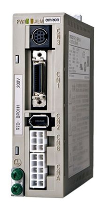
Фирма OMRON для настройки своих приводов предлагает программное обеспечение CX-Drive. Оно позволяет производить параметрирование частных преобразователей, сервоприводов и мониторинг их работы.
Внешний вид CX-Drive.
CX-Drive входит в комплект поставки общего пакета программного обеспечения CX-One фирмы OMRON. Также CX-Drive можно приобрести отдельно по стоимости что-то около 200 евро. При поставке самостоятельной версии в комплект поставки входит соединительный кабель для подключения к преобразователям. Кабедь ничего, сильно страшного, не представляет. С одной стороны обычный разъем DB-9 для COM-порта, с другой сетевая вилка RJ-45. При желании такой кабель можно изготовить самостоятельно. Напрягает только использование COM-порта. В современных ноутбуках, как правило, его нет. Требуется дополнительный переходник. При этом CX-Drive может отказаться работать с некоторыми моделями. Я использую простой преобразователь USB-COM от МастерКит. С программами для оборудования SIEMENS проблем не возикло, а CX-Drive не смог запустить обмен с инвертором, хотя и обнаруживал его. Проблема решилась установкой последних версий драйвера USB-COM.
Работа с CX-Drive достаточно проста, особенно если есть опыт общения с другим ПО от OMRON. К тому же моя версия 1.5 оказалась русифицированной, что еще больше упростило ее освоение. Некоторые сложности возникли при настройках модели привода перед началом работы, но их можно избежать если воспользоваться функцией «Автоопределение». При ее активации, программа сканирует все возможные каналы связи с преобразователем и определяет тип последнего.
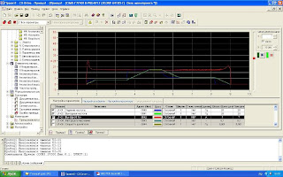
Одной из самых интересных функций программного пакета является возможность мониторинга внутренних параметров с построением графиков. При этом для инверторов можно увидеть даже такие расчетные параметры как активная и индуктивная составляющие тока при векторном управлении.
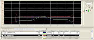
Графики тока и выходной частоты.
К сожалению, имеющаяся у меня версия 1.5, уже устарела. Например не получилось установить соединение с преобразователем F7 со специальной прошивкой S8152. Программа привод видела, но общаться с ним отказалась, ссылаясь на несовместимость прошивки. Очевидно не будут поддерживаться и новые модели инверторов. Остается надеятся, что с официального сайта www.omron.com можно загрузть обновление.
Ярослав писал(а):
Зайдите на сайт Yaskawa. Там есть собственная утилита общения с частотниками, возможно там найдете и прошивку.
Утилиту скачал еще раньше. там да, есть 1022
Но вопрос в чем:
на конвейере стоят частотники, недавно работаю, на всякий случай, сразу, из частотнтков скачал настройки, создал базу (прг у всех 1014). Скачивал программой CX — Drive,
часть частотников (V1000 омрон) вышли из строя, купили новые (яскава), там PRG 1022, а в CX-DRIVE максимум 1021.
(обновления скачал здесь на сайте, потом пробовал скачать с официального сайта,
в списке предлагаемых обновлений есть все программы CX-ONE, но CX-Drive нет)
может, то что яскава с омроном больше не работает, поэтому нет новых обновлений для частотников яскава, или я что-то не так делаю?
сейчас пробовал из CX-Drive загрузить скачанные настройки в новые частотники, внизу красная полоса о несоответствии прошивки.
вопрос:принципиально ли это, так понял, что добавлены несколько новых параметров в новой прошивке (1022) и по идее все должно работать?
если нет придется вручную перенести в яскавовскую утилиту параметры и загрузиться с нее?
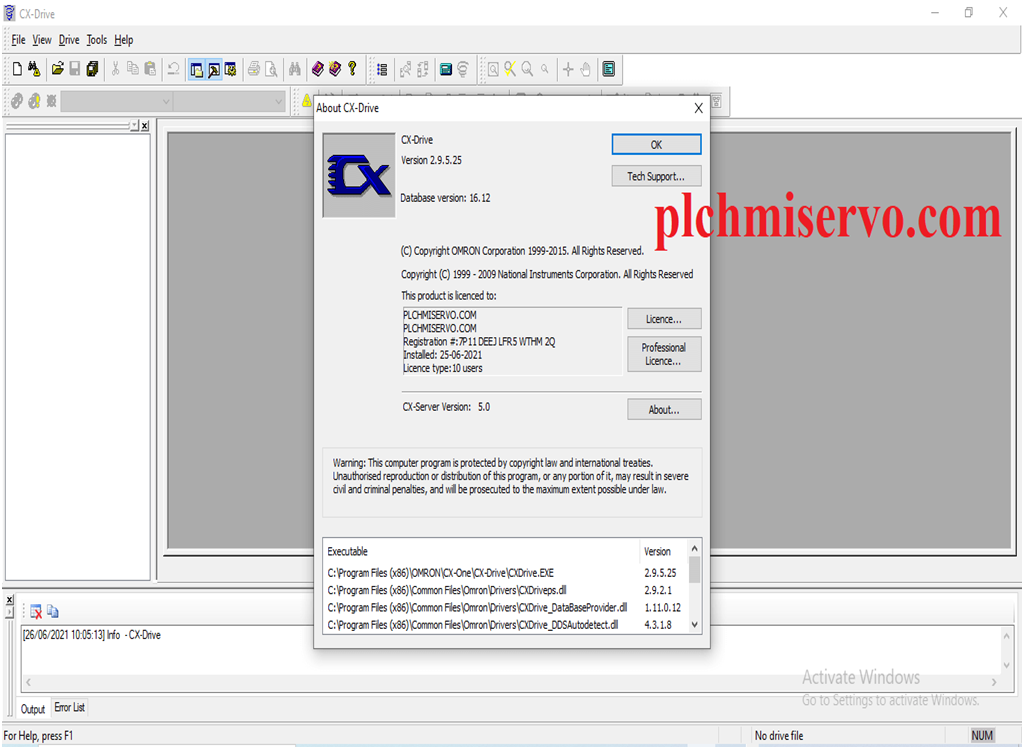
Drive CX software is the Programming software of Omron Servo Drive and VFD. CX-Drive integrated into the CX-One Software. Drive CX Used to the set parameter, performing Monitoring, Test Run, Program Upload/Download, and Data Tracing for Omron Servo Drive and VFD. We can easily find alarms of Servos and VFD through Drive CX.
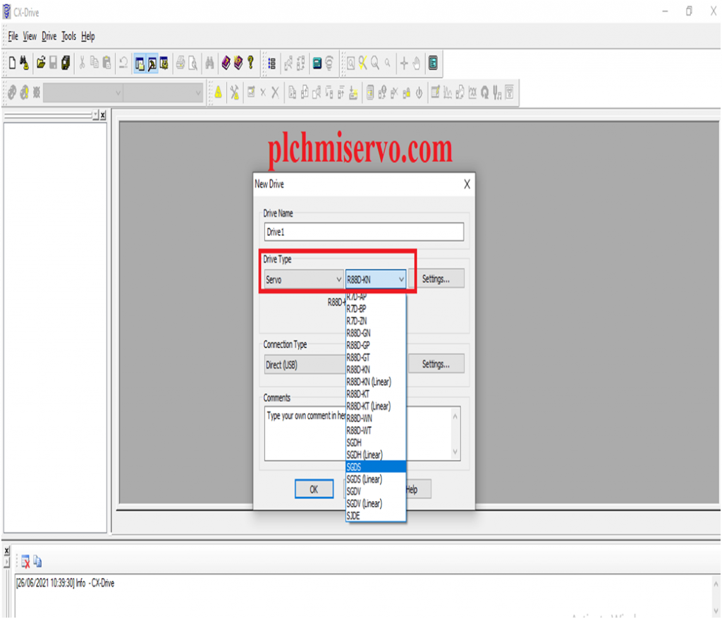
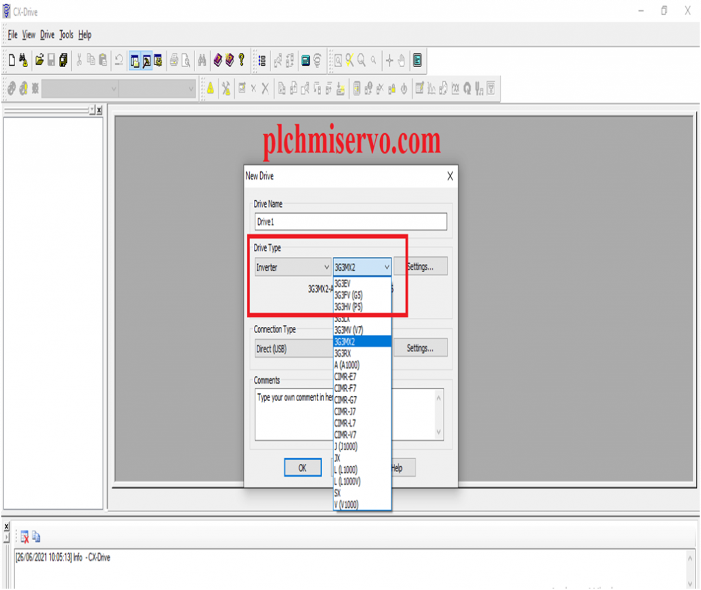
CX-Drive Supports Various types of Omron Servos and VFD
Supported Model VFD and Servo
Supported VFD: 3G3JX Series/3G3MX Series /3G3MX2 Series /3G3RX Series /3G3JV Series /3G3-MV Series and 3G3-RV Series Inverters
Supported Servos: Omron SmartStep/ SmartStep2/ Omnuc G5-series/ Omnuc G series/ Omnuc W-series Servo Drives
Upload +Download System:
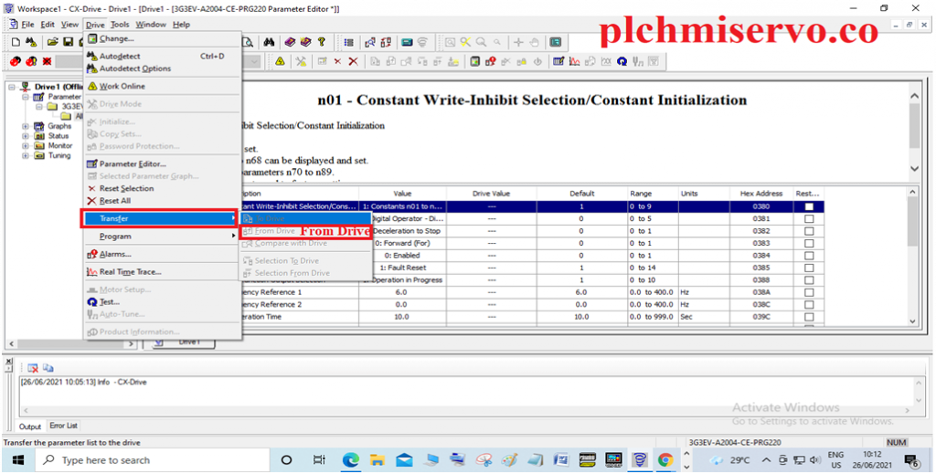
“Download”:
+>Go to the Drive then click the Transfer and click To Drive.
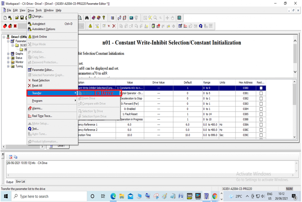
“Upload”:
^>Go to the Drives then Transfer>From Drive.
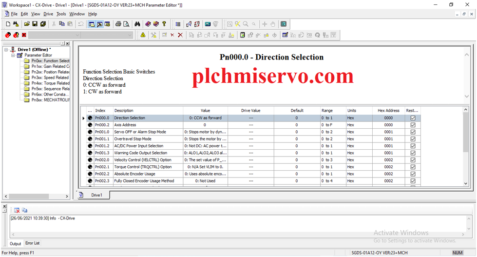
Default Parameter is shown as figure.
>>>Download Google Drive Link :
+ [Download] CX-One Omron “PLC/HMI/SERVO” Software
>>>Link:
https://drive.google.com/drive/folders/1GOVrARCAGkzYQ46IDdvvpUhLQIgPXt-K?usp=sharing
Thanks ………