Manuals Directory
Manualsdir.ru — Онлайн поиск инструкций и руководств
Руководство по эксплуатации
Cодержание
Document Outline
- Правила техники безопасности
- ОГРАНИЧЕНИЕ ОТВЕТСТВЕННОСТИ
- СОДЕРЖАНИЕ
- История редакций
- 1.- ПРОВЕРКИ ПРИ ПОЛУЧЕНИИ
- 2.- Описание изделия
- 3.- Установка аппарата
- 3.1.- РЕКОМЕНДАЦИИ ПО ПРЕДВАРИТЕЛЬНОЙ ПОДГОТОВКЕ
- 3.2.- УСТАНОВКА
- 3.3.- КЛЕММЫ АППАРАТА
- 3.3.1.- Назначение клемм, модели CVM-C10-ITF, CVM-C10-MC и CVM-C10-mV
- 3.3.2.- Назначение клемм, модели CVM-C10-ITF-IN.
- 3.3.1.- Назначение клемм, модели CVM-C10-ITF, CVM-C10-MC и CVM-C10-mV
- 3.4.- СХЕМА СОЕДИНЕНИЙ
- 3.4.1.- Измерение трехфазной сети с 4-проводным соединением, модель CVM-C10-ITF и CVM-C10-mV
- 3.4.2.- Измерение трехфазной сети с 4-проводным соединением, модель CVM-C10-ITF-IN.
- 3.4.3.- Измерение трехфазной сети с 4-проводным соединением, модель CVM-C10-MC.
- 3.4.4.- Измерение трехфазной сети с 3-проводным соединением, модель CVM-C10-ITF и CVM-C10-mV
- 3.4.5.- Измерение трехфазной сети с 3-проводным соединением, модель CVM-C10-MC.
- 3.4.6.- Измерение трехфазной сети с 3-проводным соединением и трансформаторами, соединенными по схеме Арона, модели CVM-C10-ITF, CVM-C10-MC и
- CVM-C10-mV.
- 3.4.7.- Измерение двухфазной сети с 3-проводным соединением, модели CVM-C10-ITF, CVM-C10-MC и CVM-C10-mV.
- 3.4.8.- Измерение двухфазной сети с 3-проводным соединением, модель CVM-C10-ITF-IN.
- 3.4.9.- Измерение однофазной 2-проводной сети между фазами, модели CVM-C10-ITF, CVM-C10-MC и CVM-C10-mV.
- 3.4.10.- Измерение однофазной 2-проводной сети между фазой и нейтралью, модели CVM-C10-ITF, CVM-C10-MC и CVM-C10-mV.
- 3.4.1.- Измерение трехфазной сети с 4-проводным соединением, модель CVM-C10-ITF и CVM-C10-mV
- 4.- РАБОТА
- 4.1.- ПАРАМЕТРЫ ИЗМЕРЕНИЯ
- 4.2.- НАЗНАЧЕНИЕ КНОПОК
- 4.3.1. ИНДИКАТОР COS φ — PF (КОЭФФИЦИЕНТ МОЩНОСТИ)
- 4.3.2. АНАЛОГОВЫЙ ИНДИКАТОР
- 4.3.3. ПРОЧИЕ СИМВОЛЫ ДИСПЛЕЯ
- 4.5.1. ПРОФИЛЬ АНАЛИЗАТОРА
- 4.5.2. ПРОФИЛЬ e3
- 4.6.- ГАРМОНИКИ
- 4.7.- ВХОДЫ
- 4.8.- ВЫХОДЫ
- 4.9.- ПРОГРАММИРОВАНИЕ
- 4.9.4. Вторичная обмотка трансформатора тока ( модель CVM-C10-ITF)
- 4.9.3. Первичная обмотка трансформатора тока
- 4.9.2. Вторичная обмотка трансформатора напряжения
- 4.9.5. первичного тока нейтрали( модель CVM-C10-ITF-IN)
- 4.9.6. вторичный ток нейтрали (модель CVM-C10-ITF-IN)
- 4.9.7. Количество квадрантов
- 4.9.9. Период интегрирования максимальной потребности
- 4.9.8. Тип установки
- 4.9.22. Программирование сигнала тревоги 1 (реле 1)
- 4.9.21. Коэффициент расходов для потребляемой энергии
- 4.9.20. Коэффициент расходов для генерируемой энергии
- 4.9.18. Коэффициент выбросов углекислого газа в кг C02 для генерируемой энергии
- 4.9.17. Активизация экрана отображения гармоник.
- 4.9.16. Выбор шкалы энергий
- 4.9.15. Стирание максимальных и минимальных величин
- 4.9.14. Стирание максимальных и минимальных величин
- 4.9.13. Выбор индикатора Cos φ — PF дисплея
- 4.9.12. Подсветка дисплея
- 4.9.11. Выбор профиля работы
- 4.9.10. Стирание максимальной потребности
- 4.9.23. Программирование сигнала тревоги 2 (реле 2)
- 4.9.24. Программирование сигнала тревоги 3 (цифровой выход T1)
- 4.9.25. Программирование сигнала тревоги 4 (цифровой выход T2)
- 4.9.29. Блокировка программирования
- 4.9.28. Связь RS-485 : Протокол
- 4.9.27. Режим работы цифрового входа 2
- 4.9.26. Режим работы цифрового входа 1
- 4.9.1. Первичная обмотка трансформатора напряжения
- 4.10.- СВЯЗЬ
- 4.10.1. СОЕДИНЕНИЕ
- 4.10.2. ПРОТОКОЛ
- 4.10.3. КОМАНДЫ MODBUS
- 4.10.4. ПРОТОКОЛ BACnet
- 4.10.5. СВИДЕТЕЛЬСТВО PICS
- 5.- ТЕХНИЧЕСКИЕ ХАРАКТЕРИСТИКИ
- 6.- ТЕХНИЧЕСКОЕ ОБСЛУЖИВАНИЕ И УХОД
- 7.- ГАРАНТИЯ
- 8.- СЕРТИФИКАТ СЕ

-
Contents
-
Table of Contents
-
Bookmarks
Quick Links
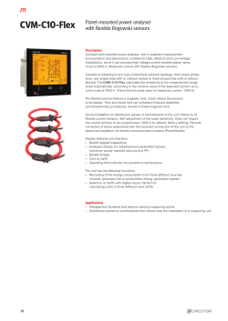
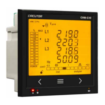
Power analyzer
CVM-C10
INSTRUCTION MANUAL
(M001B01-03-21A)
Related Manuals for Circutor CVM-C10
Summary of Contents for Circutor CVM-C10
-
Page 1
Power analyzer CVM-C10 INSTRUCTION MANUAL (M001B01-03-21A) -
Page 2
CVM-C10 Instruction Manual… -
Page 3: Safety Precautions
CIRCUTOR, SA reserves the right to make modifications to the device or the unit specifications set out in this instruction manual without prior notice. CIRCUTOR, SA on its web site, supplies its customers with the latest versions of the device specifica- tions and the most updated manuals.
-
Page 4: Table Of Contents
3�5�1�- MEASURING THREE-PHASE NETWORKS WITH A 4-WIRE CONNECTION, CVM-C10-ITF AND CVM-C10-mV MODEL� ��������������������������������������������������������������������������������������������������������������������������������������������������������������������� 15 3�5�2�- MEASURING THREE-PHASE NETWORKS WITH A 4-WIRE CONNECTION, CVM-C10-ITF-IN MODEL� ��������� 16 3�5�3�- MEASURING THREE-PHASE NETWORKS WITH A 4-WIRE CONNECTION CVM-C10-MC MODEL� ��������������� 17 3�5�4�- MEASURING THREE-PHASE NETWORKS WITH A 4-WIRE CONNECTION CVM-C10-MC-IN MODEL� ���������� 18 3�5�5�- MEASURING THREE-PHASE NETWORKS WITH A 4-WIRE CONNECTION, CVM-C10-FLEX MODEL ������������…
-
Page 5
CVM-C10 4�9�4� SECONDARY CURRENT ( MODEL CVM-C10-ITF) �������������������������������������������������������������������������������������������49 4�9�5� PRIMARY NEUTRAL CURRENT ( MODELS: CVM-C10-ITF-IN AND CVM-C10-MC-IN) ����������������������������������49 4�9�6� SECUNDARY NEUTRAL CURRENT (MODEL CVM-C10-ITF-IN) ��������������������������������������������������������������������� 50 4�9�7� NUMBER OF QUADRANTS ����������������������������������������������������������������������������������������������������������������������������� 50 4�9�8� MEASUREMENT CONVENTION ��������������������������������������������������������������������������������������������������������������������� 50 4�9�9� TYPE OF INSTALLATION ��������������������������������������������������������������������������������������������������������������������������������� 51 4�9�10�… -
Page 6: Revision Log
CVM-C10 REVISION LOG Table 1: Revision log� Date Revision Description 04/14 M001B01-03-14A Initial Version Changes in the following sections: 06/14 M001B01-03-14B 3.4 — 4.9 — 4.10 — 5 Changes in the following sections: 06/14 M001B01-03-14C 4.9.5 — 4.9.6 — 4.10.2.1…
-
Page 7: 1�- Verification Upon Reception
CIRCUTOR’s after-sales service. 2.- PRODUCT DESCRIPTION The CVM-C10 device measures, calculates and displays the main electrical parameters of the follow- ing networks: single-phase, two-phase, with and without neutral, balanced three-phase, with ARON measurements or unbalanced. The measurement will be taken in RMS with the three AC voltage inputs and three current inputs.
-
Page 8
— 2 digital outputs, fully programmable. (Not available in the CVM-C10-ITF-IN, CVM-C10-MC-IN and CVM-C10-FLEX models) — 2 alarm relays, fully programmable (Not available in the CVM-C10-FLEX model) — RS-485 Communications, with two serial protocols: MODBUS RTU© and BACnet. Instruction Manual… -
Page 9: 3�- Device Installation
The CVM-C10 device must be installed by authorised and qualified staff. The power supply plug must be disconnected and measuring systems switched off before handling, al- tering the connections or replacing the device.
-
Page 10: 3�2�- Installation
The temperature rating of insulation of wires connected to the device will be at minimum 62ºC. 3�3�- CVM-C10-FLEX: ROGOWSKI SENSORS The CVM-C10-FLEX model measures currents using flexible sensors, based on the Rogowski coil prin- ciple. The flexibility of the sensor allows it to measure an alternating current irrespective of the position of the conductor.
-
Page 11
CVM-C10 Table 3: Probe cable terminal connections Probe cable terminal connections FLEX-MAG Shield Común / Common Canal de medida / Measuring channel Black : Shield (SHLD) Blue: Common (C) Green: Measuring channel (L1, L2, L3, N) Instruction Manual… -
Page 12: 3�4�- Device Terminals
CVM-C10 3�4�- DEVICE TERMINALS 3�4�1�- LIST OF TERMINALS, CVM-C10-ITF, CVM-C10-MC AND CVM-C10-mV MODELS Table 4: List of terminals of the CVM-C10-ITF, CVM-C10-MC and CVM-C10-mV� Device terminals 1 : A1 Auxiliary power supply. 13: I2, digital input 2 / tariff selection 2: A2 Auxiliary power supply.
-
Page 13: 3�4�2�- List Of Terminals, Cvm-C10-Itf-In And Cvm-C10-Mc-In Models
CVM-C10 3�4�2�- LIST OF TERMINALS, CVM-C10-ITF-IN AND CVM-C10-MC-IN MODELS� Table 5: List of terminals of the CVM-C10-ITF-IN and CVM-C10-MC-IN� Device terminals 1 : A1 Auxiliary power supply. 12: I2, digital input 2 / tariff selection 2: A2 Auxiliary power supply.
-
Page 14: 3�4�3�- List Of Terminals, Cvm-C10-Flex Model
CVM-C10 3�4�3�- LIST OF TERMINALS, CVM-C10-FLEX MODEL Table 6: List of terminals of the CVM-C10-FLEX� Device terminals 1 : A1 Auxiliary power supply. 10: V , Voltage input L3 2: A2 Auxiliary power supply. 11: N, Neutral 3: A(+), RS485…
-
Page 15: 3�5�- Connection Diagram
S0- S0+ S0+ RS485 INPUTS A(+) B(-) I1 I2 POWER SUPPLY Rc R2 R1 Tc T2 T1 Ph-Ph Ph-N 300V ~ 520V ~ P2 P1 LOAD Figure 4: Three-Phase measuring with a 4-wire connection, CVM-C10-ITF and CVM-C10-mV model� Instruction Manual…
-
Page 16: Model
MODEL� Measurement system: Power Supply OUTPUTS RS485 INPUTS A(+) B(-) I1 I2 POWER SUPPLY Rc R2 R1 Ph-Ph Ph-N 300V ~ 520V ~ P2 P1 P2 S1 LOAD Figure 5: Three-Phase Measuring with a 4-wire connection, CVM-C10-ITF-IN model� Instruction Manual…
-
Page 17: 3�5�3�- Measuring Three-Phase Networks With A 4-Wire Connection Cvm-C10-Mc Model
CVM-C10 3�5�3�- MEASURING THREE-PHASE NETWORKS WITH A 4-WIRE CONNECTION CVM-C10-MC MODEL� Measurement system: Power Supply OUTPUTS S0- S0+ S0+ RS485 INPUTS A(+) B(-) I1 I2 POWER SUPPLY Rc R2 R1 Tc T2 T1 Ph-Ph Ph-N 300V ~ 520V ~ P2 P1 LOAD Figure 6: Three-Phase measuring with a 4-wire connection, CVM-C10-MC model�…
-
Page 18: 3�5�4�- Measuring Three-Phase Networks With A 4-Wire Connection Cvm-C10-Mc-In Model
300V ~ 520V ~ P2 P1 LOAD Figure 7: Three-Phase measuring with a 4-wire connection, CVM-C10-MC-IN model� Note: Do not connect MC current transformers to ground. The MC transformer secondary value is set to 0.250 A (fixed value) Instruction Manual…
-
Page 19: 3�5�5�- Measuring Three-Phase Networks With A 4-Wire Connection, Cvm-C10-Flex Model
CVM-C10 3�5�5�- MEASURING THREE-PHASE NETWORKS WITH A 4-WIRE CONNECTION, CVM-C10-FLEX MO- Measurement system: Power Supply RS485 INPUTS A(+) B(-) I1 I2 POWER SUPPLY Ph-Ph Ph-N FLEX-MAG (100mV~ ) 300V ~ 520V ~ L1 L2 L3 LN C SHLD SHLD LOAD Figure 8: Three-Phase measuring with a 4-wire connection, CVM-C10-FLEX model�…
-
Page 20: Model
INPUTS A(+) B(-) I1 I2 POWER SUPPLY Rc R2 R1 Tc T2 T1 Ph-Ph Ph-N 300V ~ 520V ~ P2 P1 P2 S1 P2 S1 LOAD Figure 9: Three-Phase measuring with a 3-wire connection, CVM-C10-ITF and CVM-C10-mV model� Instruction Manual…
-
Page 21: 3�5�7�- Measuring Three-Phase Networks With A 3-Wire Connection, Cvm-C10-Mc Model
CVM-C10 3�5�7�- MEASURING THREE-PHASE NETWORKS WITH A 3-WIRE CONNECTION, CVM-C10-MC MODEL� Measurement system: Power Supply OUTPUTS S0- S0+ S0+ RS485 INPUTS A(+) B(-) I1 I2 POWER SUPPLY Rc R2 R1 Tc T2 T1 Ph-Ph Ph-N 300V ~ 520V ~ P2 P1 LOAD Figure 10: Three-Phase measuring with a 3-wire connection, CVM-C10-MC model�…
-
Page 22: 3�5�8�- Measuring Three-Phase Networks With A 3-Wire Connection, Cvm-C10-Flex Model
CVM-C10 3�5�8�- MEASURING THREE-PHASE NETWORKS WITH A 3-WIRE CONNECTION, CVM-C10-FLEX MO- DEL� Measurement system: Power Supply RS485 INPUTS A(+) B(-) I1 I2 POWER SUPPLY Ph-Ph Ph-N 300V ~ 520V ~ FLEX-MAG (100mV~ ) L2 L3 LN C SHLD SHLD LOAD Figure 11: Three-Phase measuring with a 3-wire connection, CVM-C10-FLEX model�…
-
Page 23: 3�5�9�- Measuring Three-Phase Networks With A 3-Wire Connection And Transformers With An Aron Connection, Cvm-C10-Itf And Cvm-C10-Mc Models
300V ~ 520V ~ P2 P1 LOAD Figure 12: Three-Phase measuring with a 3-wire connection and transformers with an ARON connection, CVM-C10-ITF and CVM- C10-MC and models� Note: Do not connect MC current transformers to ground. CVM-C10-ITF model: The transformer secondary value must be 5A or 1A CVM-C10-MC model: The MC transformer secondary value is set to 0.250 A (fixed value)
-
Page 24: Cvm-C10-Mv Models
300V ~ 520V ~ P2 P1 LOAD Figure 13: Measuring Two-Phase Networks with a 3-wire connection, CVM-C10-ITF, CVM-C10-MC and CVM-C10-mV models� Note: Do not connect MC current transformers to ground. CVM-C10-ITF model: The transformer secondary value must be 5A or 1A CVM-C10-MC model: The MC transformer secondary value is set to 0.250 A (fixed value)
-
Page 25: Cvm-C10-Mc-In Models
300V ~ 520V ~ P2 P1 LOAD Figure 14: Measuring Two-Phase Networks with a 3-wire connection, CVM-C10-ITF-IN and CVM-C10-MC-IN models� Note: Do not connect MC current transformers to ground. CVM-C10-ITF-IN model: The transformer secondary value must be 5A or 1A CVM-C10-MC-IN model: The MC transformer secondary value is set to 0.250 A (fixed value)
-
Page 26: 3�5�12�- Measuring Two-Phase Networks With A 3-Wire Connection, Cvm-C10-Flex Model
POWER SUPPLY Ph-Ph Ph-N 300V ~ 520V ~ FLEX-MAG (100mV~ ) L2 L3 LN C SHLD SHLD LOAD Figure 15: Measuring Two-Phase Networks with a 3-wire connection, CVM-C10-FLEX model� It is mandatory connect the SHLD terminal of the probe. Instruction Manual…
-
Page 27: 3�5�13�- Measuring Single-Phase Networks, Phase To Phase, With A 2-Wire Connection, Cvm-C10-Itf, Cvm-C10-Mc And Cvm-C10-Mv Models
300V ~ 520V ~ P2 P1 LOAD Figure 16: Measuring Single-Phase Networks, phase to phase, with a 2-wire connection, CVM-C10-ITF, CVM-C10-MC and CVM-C10- mV models� Note: Do not connect MC current transformers to ground. CVM-C10-ITF model: The transformer secondary value must be 5A or 1A CVM-C10-MC model: The MC transformer secondary value is set to 0.250 A (fixed value)
-
Page 28: Cvm-C10-Flex Model
300V ~ 520V ~ FLEX-MAG (100mV~ ) L2 L3 LN C SHLD SHLD LOAD Figure 17: Measuring Single-Phase Networks, phase to phase, with a 2-wire connection, CVM-C10-FLEX model� It is mandatory connect the SHLD terminal of the probe. Instruction Manual…
-
Page 29: 3�5�15�- Measuring Single-Phase Networks, Phase To Neutral, With A 2-Wire Connection, Cvm-C10-Itf, Cvm-C10-Mc And Cvm-C10-Mv Models
300V ~ 520V ~ P2 P1 LOAD Figure 18: Measuring Single-Phase Networks, phase to neutral, with a 2-wire connection, CVM-C10-ITF, CVM-C10-MC and CVM- C10-mV models� Note: Do not connect MC current transformers to ground. CVM-C10-ITF model: The transformer secondary value must be 5A or 1A CVM-C10-MC model: The MC transformer secondary value is set to 0.250 A (fixed value)
-
Page 30: Cvm-C10-Flex Model
300V ~ 520V ~ FLEX-MAG (100mV~ ) L2 L3 LN C SHLD SHLD LOAD Figure 19: Measuring Single-Phase Networks, phase to neutral, with a 2-wire connection, CVM-C10-FLEX model� It is mandatory connect the SHLD terminal of the probe. Instruction Manual…
-
Page 31: 4�- Operation
CVM-C10 4.- OPERATION The CVM-C10 is a four-quadrant power analyzer (consumption and generation). The device can operate according to three different measurement conventions: CIRCUTOR measurement convention. IEC measurement convention. IEEE measurement convention. The measurement convention is configured in the setup menu, see “4.9.8. Measurement convention”.
-
Page 32: 4�1�- Measuring Parameters
P > 0 Q < 0 > Figure 22: Convenio de medida IEEE� 4�1�- MEASURING PARAMETERS The device displays the electrical parameters shown in Table 7 Table 7: Measuring parameters of the CVM-C10� Phases Total Parameter Units L1-L2-L3 Phase-neutral voltage Vph-N …
-
Page 33: 4�2�- Keyboard Functions
4�2�- KEYBOARD FUNCTIONS The CVM-C10 has 3 keys that allow you to browse between the various screens and program the de- vice. Key functions on measuring screens ( Table 8 Table 8: Key functions on measuring screens�…
-
Page 34
CVM-C10 Table 8 (Continuation): Key functions on measuring screens� Long keystroke Short keystroke (2 s) Browsing the different profiles Accessing the programming menu (analyzer, user, e3) Display of the Maximum Demand Active alarm information Unlocks the active alarm Key functions on harmonics screens ( Table 9 Table 9: Key functions on harmonics screens�… -
Page 35: 4�3�- Display
Table 3 The display is divided into four areas ( Figure 23 Figure 23: CVM-C10 Display areas The area with data per phase displays the instantaneous, maximum and minimum values of each phase being measured or calculated by the device.
-
Page 36: 4�3�2� Analogue Bar
CVM-C10 4�3�2� ANALOGUE BAR Figure 25: Analogue Bar The analogue bar displays two parameters: Current power of the installation in % This parameter is displayed in 12 divisions, each one represents 10%, into which the analogue bar is divided.
-
Page 37: 4�4�- Led Indicators
— KEY, LED that is lit when any key is pressed. Figure 26: LED Indicators of the CVM-C10� 4�5�- OPERATION PROFILES The CVM-C10 has 3 operation profiles. The display screens will be opened for the corresponding profile: Analyzer profile, analyzer, Electrical energy efficiency profile, e …
-
Page 38
CVM-C10 Use keys to browse the different screens. The inst symbol on the bottom of the screen indicates that the values being displayed are of the instantaneous type. Table 12: Analyzer profile screens� Screen Parameters (units) phase-phase Voltage L1-L2 (V… -
Page 39
CVM-C10 Table 12 (Continuation): Analyzer profile screens� Screen Parameters (units) Apparent Power L1 (M/KVA) Apparent Power L2 (M/KVA) Apparent Power L3 (M/KVA) Apparent Power III (M/KVA) The generation values are not measured when the 2 quadrant option is selected. Inductive Reactive Power L1 (M/Kvar… -
Page 40
CVM-C10 Table 12 (Continuation): Analyzer profile screens� Screen Parameters (units) Power factor L1 (PF) Power factor L2 (PF) Power factor L3 (PF) Power factor III (PF) Cos φ L1 (cos φ) Cos φ L2 (cos φ) Cos φ L3 (cos φ) Cos φ… -
Page 41
CVM-C10 Figure 29: Analyzer profile screen displaying the minimum values� Maximum Demand The device calculates the maximum demand of the following: • Current • Three-Phase Active Power. • Three-Phase Apparent Power. • Three-Phase Inductive Reactive Power • Three-Phase Capacitive Reactive Power… -
Page 42: 4�5�2� E 3 Profile
This profile is identified with the e symbol on the bottom of the screen ( Figure 31 Figure 31: CVM-C10 screen with the e profile� The installation’s consumed and generated energy are displayed on the e profile of the device.
-
Page 43
CVM-C10 Table 13 (Continuation): Screens of the e profile� Screen Parameters (units) Inductive Reactive Energy Tariff 1, T1 (M/Kvar Inductive Reactive Energy Tariff 2, T2 (M/Kvar Inductive Reactive Energy Tariff 3, T3 (M/Kvar Total Inductive Reactive Energy (M/Kvar Consumption and generation values Only available for the 4 quadrant option. -
Page 44: 4�5�3� User
This profile is identified with the user symbol on the bottom of the screen ( Figure 32 Figure 32: Screen of the CVM-C10 with the user profile� This profile displays the screens selected in the programming menu ( “4.9.12. Selecting the operation profile”…
-
Page 45: 4�7�- Inputs
Figure 1 and ), fully programmable, see “4.9.25. Programming alarm 3 (Digital output T1)” “4.9.26. Figure 3 Programming alarm 4 (Digital output T2)”. Note: The digital outputs are not available on models CVM-C10-ITF-IN, CVM-C10-MC-IN and CVM- C10-FLEX Instruction Manual…
-
Page 46: 4�9�- Programming
CVM-C10 4�9�- PROGRAMMING From the programming menu you can: Lock the status of the menu. Define the transformation ratios. Select the number of quadrants and type of installation. Select the operation profile of the device. Program the carbon emission ratio, kgCO …
-
Page 47: 4�9�1� Primary Voltage
CVM-C10 When the desired value is shown on the screen, move onto the next digit by pressing the key modify the other values. If you press the key after changing the last digit, it will jump back to the first digit so you can modify the previously programmed values again.
-
Page 48: 4�9�2� Secondary Voltage
CVM-C10 4�9�2� SECONDARY VOLTAGE On this screen the voltage transformer secondary is programmed. Press key for 3 seconds to edit the transformer secondary value. The prog icon will be displayed on the bottom of the screen. To enter or modify the value, press the key repeatedly, increasing the value of the flashing digit.
-
Page 49: 4�9�4� Secondary Current ( Model Cvm-C10-Itf)
To validate the data, press Press key to access the next programming step 4�9�5� PRIMARY NEUTRAL CURRENT ( MODELS: CVM-C10-ITF-IN AND CVM-C10-MC-IN) The neutral current transformer primary is programmed on this screen. Press key for 3 seconds to edit the transformer primary value. The prog icon will be displayed on the bottom of the screen.
-
Page 50: 4�9�6� Secundary Neutral Current (Model Cvm-C10-Itf-In)
CVM-C10 4�9�6� SECUNDARY NEUTRAL CURRENT (MODEL CVM-C10-ITF-IN) The neutral current transformer secundary is programmed on this screen. Press key for 3 seconds to edit the transformer secundary value. The prog icon will be displayed on the bottom of the screen.
-
Page 51: 4�9�9� Type Of Installation
CVM-C10 Press key to access the next programming step. 4�9�9� TYPE OF INSTALLATION The type of installation is selected on this screen. Press key for 3 seconds to edit the type of installation. The prog icon will be displayed on the bottom of the screen.
-
Page 52: 4�9�11� Deleting Maximum Demand
CVM-C10 Note: Programming the value 0 disables the calculation of the maximum demand. Press key to access the next programming step. 4�9�11� DELETING MAXIMUM DEMAND On this screen you select whether or not to delete the maximum demand. Press key for 3 seconds to edit the deletion selection.
-
Page 53: 4�9�13� Backlight, Turning On The Backlit Display
CVM-C10 the display screens are those that were stored in previous programming settings of the device. (In the case of new devices, these will be the same as those of the analyzer profile) , the display screens are selected. To validate the data, press for 3 seconds and the prog icon will disappear from the display.
-
Page 54: 4�9�14� Selecting The Cos Φ — Pf Bar On The Display
CVM-C10 To validate the data, press for 3 seconds and the prog icon will disappear from the display. Maximum programming value: 99 seconds. Minimum programming value: 0 seconds. Note: The value 00 indicates that the backlight will stay permanently lit.
-
Page 55: 4�9�17� Selecting The Range Of Energies
CVM-C10 for 3 seconds and the prog icon will disappear from the display. To validate the data, press Press key to access the next programming step. 4�9�17� SELECTING THE RANGE OF ENERGIES The operation of the range of energy is selected on this screen.
-
Page 56: Carbon Emission Ratio Of Generated Energy
CVM-C10 4�9�19� kgC0 CARBON EMISSION RATIO OF GENERATED ENERGY The carbon emissions ratio is the amount of emissions released into the atmosphere to produce a unit of electricity (1 kWh). The ratio for the European mix is approximately 0.65 kgCO per kWh.
-
Page 57: 4�9�21� Cost Ratio Of Generated Energy
CVM-C10 If you press the key after changing the last digit, it will jump back to the first digit so you can modify the previously programmed values again. Press key to browse the different tariffs. for 3 seconds and the prog icon will disappear from the display.
-
Page 58: 4�9�22� Cost Ratio Of Consumed Energy
Press key to access the next programming step. 4�9�23� PROGRAMMING ALARM 1 (RELAY 1) Note: Configuration parameters not available for the CVM-C10-FLEX model. The variable code is selected on this screen, depending on Table 15, which will control alarm relay 1.
-
Page 59
CVM-C10 If you press the key after changing the last digit, it will jump back to the first digit so you can modify the previously programmed values again. To validate the data, press for 3 seconds and the prog icon will disappear from the display. -
Page 60
CVM-C10 Programming the maximum value The maximum value: the alarm is activated when this value is exceeded. Press key for 3 seconds to edit the maximum value selection. The prog icon will be displayed on the bottom of the screen. -
Page 61
CVM-C10 Programming the minimum value The minimum value: the alarm is activated below this value. Press key for 3 seconds to edit the minimum value selection. The prog icon will be displayed on the bottom of the screen. To enter or modify the value, press the key repeatedly, increasing the value of the flashing digit. -
Page 62
CVM-C10 Programming the hysteresis value The hysteresis value, i.e., difference between the alarm connection and disconnection value, in %, is programmed on this screen. Press key for 3 seconds to edit the hysteresis value selection. The prog icon will be displayed on the bottom of the screen. -
Page 63: 4�9�24� Programming Alarm 2 (Relay 2)
“4.9.23. Programming alarm 1 (Relay 1)” 4�9�25� PROGRAMMING ALARM 3 (DIGITAL OUTPUT T1) Note: Configuration parameters not available for the CVM-C10-FLEX, CVM-C10-ITF-IN and CVM-C10- MC-IN models. All values for digital output T1 are programmed on this screen. The variable code is selected on this screen, depending on Table 15 which will control digital output T1.
-
Page 64
CVM-C10 for 3 seconds to edit the code selection. The prog icon will be displayed on the bottom Press key of the screen. To enter or modify the value, press the key repeatedly, increasing the value of the flashing digit. -
Page 65
CVM-C10 Programming kilowatts per pulse Press key for 3 seconds to edit the kilowatts per pulse selection. The prog icon will be displayed on the bottom of the screen. To enter or modify the value, press the key repeatedly, increasing the value of the flashing digit. -
Page 66: 4�9�26� Programming Alarm 4 (Digital Output T2)
Maximum programming value: 500 ms. Minimum programming value: 30 ms. 4�9�26� PROGRAMMING ALARM 4 (DIGITAL OUTPUT T2) Note: Configuration parameters not available for the CVM-C10-FLEX, CVM-C10-ITF-IN and CVM-C10- MC-IN models. All values for digital output T2 are programmed on this screen.
-
Page 67: 4�9�29� Rs-485 Communications: Protocol
CVM-C10 4�9�29� RS-485 COMMUNICATIONS: PROTOCOL The RS-485 communications protocol is selected on this screen. Press the key for 3 seconds to edit the function selection. The prog icon will be displayed on the bottom of the screen. Press key to browse the two options:…
-
Page 68
CVM-C10 for 3 seconds and the prog icon will disappear from the display. To validate the data, press Press key to access the next programming step. Parity The type of parity of Modbus communications is selected on this screen. -
Page 69
CVM-C10 4�9�29�2 BACnet protocol Note: Protocol available in devices with version 3.00 or higher. Transmission speed The transmission speed of BACnet communications is programmed on this screen. Press key for 3 seconds to edit the transmission speed selection. The prog icon will be displayed on the bottom of the screen. -
Page 70: 4�9�30� Locking The Programming
CVM-C10 When the desired value is shown on the screen, press the key to go to the next digit and modify the other values. If you press the key after changing the last digit, it will jump back to the first digit so you can modify the previously programmed values again.
-
Page 71
CVM-C10 To validate the data, press for 3 seconds and the prog icon will disappear from the display. Default password: 1234. This value may only be modified through communications. See “4.10.3.8.17. Password configuration.” Press the key to exit the setup menu. -
Page 72: 4�10�- Communications
CVM-C10 and the master device of 1200 metres. A maximum of 32 CVM-C10 devices can be connected to this bus. Use an intelligent RS-232 to RS-485 network protocol converter to establish the communications with the master device.
-
Page 73: 4�10�2� Protocol
CVM-C10 4�10�2� PROTOCOL In the Modbus protocol, the CVM-C10 device uses the RTU (Remote Terminal Unit) mode. The Modbus functions implemented in the device are as follows: Function 0x03 and 0x04: Reading integer logs. Function 0x05: Writing a relay. Function 0x10: Writing multiple logs.
-
Page 74: 4�10�3� Modbus Commands
CVM-C10 Response: Initial Address Function Value Register 0834 FF00 CEEF 4�10�3� MODBUS COMMANDS 4�10�3�1� Measurement variables� All the adresses of Modbus memory are in Hexadecimal. For these variables is implemented the Function 0x03 and 0x04� Table 19: Modbus memory map (Table 1)
-
Page 75
CVM-C10 Table 19 (Continuation): Modbus memory map (Table 1) Parameter Symbol Instantaneous Maximum Minimum Units L3-L1 Voltage 42-43 148-149 1A6-1A7 V x 10 Neutral Current N 44-45 14A-14B 1A8-1A9 L1 voltage % THD %THDV1 46-47 14C-14D 1AA-1AB % x 10… -
Page 76
CVM-C10 Table 20 (Continuation): Modbus memory map (Table 2) Parameter Symbol Tariff 1 Tariff 2 Tariff 3 Total Units Generated capacitive reactive energy kvarhC III 7C-7D A6-A7 D0-D1 FA-FB varh (varhC) Generated apparent energy (kVAh) kVAh III 7E-7F A8-A9 D2-D3… -
Page 77
CVM-C10 Table 21 (Continuation) : Modbus memory map (Table 3)� Parameter L1 Voltage L2 Voltage L3 Voltage Units 31st Order harmonic % x 10 Table 22: Modbus memory map (Table 4)� Parameter L1 Current L2 Current L3 Current Units Fundamental Harm. -
Page 78
CVM-C10 Table 23: Modbus memory map: Deleting parameters� Parameters Address Valid data margin FF00 Deleting energies FF00 Deleting maximum and minimum values Starting maximum demand FF00 Deleting the hour counters (All tariffs) FF00 Deleting the maximum value of the maximum demand… -
Page 79
Neutral current secondary 271B 5: ../5 A All variables must be programmed at the same time. This variable is only programmed for the CVM-C10-ITF-IN model. 4�10�3�8�3� Number of quadrants Table 30: Modbus memory map: Number of quadrants Maximum demand Default… -
Page 80
CVM-C10 4�10�3�8�5� Type of installation Table 32: Modbus memory map: Type of installation Type of installation Default Configuration variable Address Valid data margin value Three-phase network with 4 wires� Three-phase network with 3 wires. Three-phase network with 3 wires, Aron. -
Page 81
They have 1 decimal place. (10) 4�10�3�8�12� Programming alarms 1 and 2 (Relays 1 and 2) Note: Configuration parameters not available for the CVM-C10-FLEX model. Table 39: Modbus memory map: Programming alarms 1 and 2� Programming alarms 1 and 2… -
Page 82
CVM-C10 4�10�3�8�13� Programming alarms 3 and 4 (Digital outputs T1 and T2) Note: Configuration parameters not available for the CVM-C10-FLEX , CVM-C10-ITF-IN and CVM-C10- MC-IN models. Table 40: Modbus memory map: Programming alarms 3 and 4� Programming alarms 3 and 4… -
Page 83
CVM-C10 Table 45: Variable format: Status of the digital outputs� Bit 7 Bit 6 Bit 5 Bit 4 Bit 3 Bit 2 Bit 1 Bit 0 Output 4 Output 3 Output 2 Output 1 0: OFF 0: OFF 0: OFF… -
Page 84: 4�10�4� Bacnet Protocol
CVM-C10 4�10�4� BACnet PROTOCOL BACnet is a communications protocol for Building Automation and Control NETworks. This protocol replaces the proprietary communications of each device, making it a set of common communication rules that enables the complete integration of the building automation and control devices of different manufacturers.
-
Page 85: 4�10�5� Mapa Pics
CVM-C10 4�10�5� MAPA PICS PICS Vendor Name: CIRCUTOR Product Name: CVM-C10 Product Model Number: 0116 Application Software Version: 1.0 Firmware Revision: 0.7.1 BACnet Protocol Revision: Product Description: Electrical energy meter BACnet Standardized Device Profile (Annex L) BACnet Application Specific Controller (B-ASC)
-
Page 86
CVM-C10 DESCRIPTION SYMBOL ID OBJECTS OBJECT NAME UNITS Potencia reactiva Reactive power kvar 2 ReactPwrPh2 kvar Factor de potencia Power factor PF 2 PwrFactPh2 Tensión fase-neutro Voltage phase to neutral AI10 Ph2NU3 Corriente Current AI11 Ph3Current Potencia activa Active power… -
Page 87
CVM-C10 DESCRIPTION SYMBOL ID OBJECTS OBJECT NAME UNITS Máxima demanda I1 Maximum demand I1 Md (A1) AI44 MaxDemand_A1 Máxima demanda I2 Maximum demand I2 Md(A2) AI45 MaxDemand_A2 Máxima demanda I3 Maximum demand I3 Md(A3) AI46 MaxDemand_A3 Máxima demanda A Maximum demand A… -
Page 88: 5�- Technical Features
CVM-C10 5.- TECHNICAL FEATURES AC Power supply Rated voltage 95 … 240 V ± 10% Frequency 50 … 60 Hz Consumption 4 … 6 VA Installation category CAT III 300 V DC Power supply Rated voltage 105 … 272 V ±…
-
Page 89
Maximum current 50 mA Maximum frequency 16 impulses / sec Pulse width 30 ms to 500 ms (Programmable) Relay outputs (CVM-C10-ITF, CVM-C10-ITF-IN, CVM-C10-MC, CVM-C10-MC-IN, CVM-C10-mV ) (19) Quantity Max� voltage open contacts 250 V ~ Maximum current Maximum switching power… -
Page 90
5 … 95% Maximum altitude 2000 m IP21 Protection degree (20) Front panel: IP51 (IP64 with accessory) Environmental features (CVM-C10-MC, CVM-C10-MC-IN, CVM-C10-mV and CVM-C10-FLEX) Operating temperature -5ºC … +45ºC Storage temperature -10ºC … +50ºC Relative humidity (non-condensing) 5 … 95%… -
Page 91
Electromagnetic compatibility (EMC)� Generic standards� Emission standard BS EN 61000-6-4 for industrial environments Safety requirements for electrical equipment for measurement, control, and UL/CSA 61010-1 3rd edition laboratory use — Part 1: General requirements 60.9 96.7 10.9 Figure 35: Dimensions of the CVM-C10� Instruction Manual… -
Page 92: 6�- Maintenance And Technical Service
CVM-C10 6.- MAINTENANCE AND TECHNICAL SERVICE In the case of any query in relation to device operation or malfunction, please contact the CIRCUTOR, SA Technical Support Service. Technical Assistance Service Vial Sant Jordi, s/n, 08232 — Viladecavalls (Barcelona) Tel: 902 449 459 ( España) / +34 937 452 919 (outside of Spain) email: sat@circutor.com…
-
Page 93: 8�- Ce Certificate
CVM-C10 8.- CE CERTIFICATE Instruction Manual…
-
Page 94
CVM-C10 Instruction Manual… -
Page 95
CVM-C10 Instruction Manual… -
Page 96
CIRCUTOR, SA Vial Sant Jordi, s/n 08232 -Viladecavalls (Barcelona) Tel.: (+34) 93 745 29 00 — Fax: (+34) 93 745 29 14 www.circutor.com central@circutor.com…
Instruction manual
Table of contents
Document Outline
- Safety precautions
- DISCLAIMER
- CONTENTS
- Revision log
- 1.- VERIFICATION UPON RECEPTION
- 2.- Product description
- 3.- Unit installation
- 3.1.- PRIOR RECOMMENDATIONS
- 3.2.- INSTALLATION
- 3.3.- UNIT TERMINALS
- 3.3.1.- List of terminals, CVM-C10-ITF, CVM-C10-MC and CVM-C10-mV models
- 3.3.2.- List of terminals, CVM-C10-ITF-IN models.
- 3.3.1.- List of terminals, CVM-C10-ITF, CVM-C10-MC and CVM-C10-mV models
- 3.4.- CONNECTION DIAGRAM
- 3.4.1.- Measuring Three-Phase Networks with a 4-wire connection, CVM-C10-ITF and
- CVM-C10-mV model.
- 3.4.2.- Measuring Three-Phase Networks with a 4-wire connection, CVM-C10-ITF-IN model.
- 3.4.3.- Measuring Three-Phase Networks with a 4-wire connection, CVM-C10-MC model.
- 3.4.4.- Measuring Three-Phase Networks with a 3-wire connection, CVM-C10-ITF and
- CVM-C10-mV model.
- 3.4.5.- Measuring Three-Phase Networks with a 3-wire connection, CVM-C10-MC model.
- 3.4.6.- Measuring Three-Phase Networks with a 3-wire connection and transformers with an ARON connection, CVM-C10-ITF, CVM-C10-MC and CVM-C10-mV models.
- 3.4.7.- Measuring Two-Phase Networks with a 3-wire connection, CVM-C10-ITF, CVM-C10-MC and CVM-C10-mV models.
- 3.4.8.- Measuring Two-Phase Networks with a 3-wire connection, CVM-C10-ITF-IN model.
- 3.4.9.- Measuring Single-Phase Networks, phase to phase, with a 2-wire connection, CVM-C10-ITF, CVM-C10-MC and CVM-C10-mV models.
- 3.4.10.- Measuring Single-Phase Networks, phase to neutral, with a 2-wire connection, CVM-C10-ITF, CVM-C10-MC and CVM-C10-mV models.
- 3.4.1.- Measuring Three-Phase Networks with a 4-wire connection, CVM-C10-ITF and
- 4.- OPERATION
- 4.1.- MEASURING PARAMETERS
- 4.2.- KEYBOARD FUNCTIONS
- 4.3.1. COS φ — PF (POWER FACTOR) BAR
- 4.3.2. ANALOGUE BAR
- 4.3.3. OTHER SYMBOLS ON THE DISPLAY
- 4.4.- LED INDICATORS
- 4.5.- OPERATION PROFILES
- 4.5.2. e3 PROFILE
- 4.6.- HARMONICS
- 4.7.- INPUTS
- 4.8.- OUTPUTS
- 4.9.- PROGRAMMING
- 4.9.2. Secondary voltage
- 4.9.4. Secondary current ( model CVM-C10-ITF)
- 4.9.5. Primary neutral current ( model CVM-C10-ITF-IN)
- 4.9.6.Secundary neutral current (model CVM-C10-ITF-IN)
- 4.9.7. Number of quadrants
- 4.9.10. Deleting maximum demand
- 4.9.9. Maximum demand integration period
- 4.9.8. Type of installation
- 4.9.22. Programming alarm 1 (Relay 1)
- 4.9.21. Cost Ratio of consumed energy
- 4.9.19. kgC02 carbon emission ratio of consumed energy
- 4.9.18. kgC02 carbon emission ratio of generated energy
- 4.9.17. Activating the harmonics display screen.
- 4.9.16. Selecting the Range of energies
- 4.9.15. Deleting energy values
- 4.9.14. Deleting maximum and minimum values
- 4.9.13. Selecting the Cos φ — PF bar on the display
- 4.9.12. Backlight, Turning on the backlit display
- 4.9.11. Selecting the operation profile
- 4.9.23. Programming alarm 2 (Relay 2)
- 4.9.24. Programming alarm 3 (Digital output T1)
- 4.9.25. Programming alarm 4 (Digital output T2)
- 4.9.29. Locking the programming
- 4.9.28. RS-485 communications: Protocol
- 4.9.27. Operating mode of digital input 2
- 4.9.26. Operating mode of digital input 1
- 4.9.1. Primary voltage
- 4.9.3. Primary current
- 4.9.20. Cost Ratio of generated energy
- 4.10.- COMMUNICATIONS
- 4.10.2. PROTOCOL
- 4.10.3. COMANDOS MODBUS
- 4.10.4. BACnet PROTOCOL
- 4.10.5. MAPA PICS
- 5.- TECHNICAL FEATURES
- 6.- MAINTENANCE AND TECHNICAL SERVICE
- 7.- GUARANTEE
- 8.- CE CERTIFICATE
Вы здесь
Каталог инструкций » C » CIRCUTOR » Измерительные приборы CIRCUTOR » CIRCUTOR CVM-C10 Series » Страница инструкции 1
-

1
-
2
-
3
-
4
-
5
-
6
-
7
-
8
-
9
-
10
-
11
-
12
-
13
-
14
-
15
-
16
-
17
-
18
-
19
-
20
-
21
-
22
-
23
-
24
-
25
-
26
-
27
-
28
-
29
-
30
-
31
-
32
-
33
-
34
-
35
-
36
-
37
-
38
-
39
-
40
-
41
-
42
-
43
-
44
-
45
-
46
-
47
-
48
-
49
-
50


- 1
- 2
- ››
Распечатать
Страница 1 из
- << Предыдущая
- Следующая >>

Руководство по эксплуатации в инструкции по эксплуатации CIRCUTOR CVM-C10 Series
РУКОВОДСТВО ПО ЭКСПЛУАТАЦИИ
(M001B01-04-15A)
Анализатор цепей
CVM-C10
- << Предыдущая
- Следующая >>
-
Contents
-
Table of Contents
-
Bookmarks
Quick Links
Power analyzer
CVM-C10
INSTRUCTION MANUAL
(M001B01-03-17A)
Related Manuals for Circutor CVM-C10
Summary of Contents for Circutor CVM-C10
-
Page 1
Power analyzer CVM-C10 INSTRUCTION MANUAL (M001B01-03-17A) -
Page 2
CVM-C10 Instruction Manual… -
Page 3: Safety Precautions
CIRCUTOR, SA reserves the right to modify features or the product manual without prior notifi cation. DISCLAIMeR CIRCUTOR, SA reserves the right to make modifi cations to the device or the unit specifi ca- tions set out in this instruction manual without prior notice.
-
Page 4: Table Of Contents
3�2�- INSTALLATION ���������������������������������������������������������������������������������������������������������������������������������������� 10 3�3�- CVM-C10-fLeX: ROgOWSKI SeNSORS ����������������������������������������������������������������������������������������������� 10 3�4�- UNIT TeRMINALS ������������������������������������������������������������������������������������������������������������������������������������ 12 3�4�1�- LIST Of TeRMINALS, CVM-C10-ITf, CVM-C10-MC AND CVM-C10-mV MODeLS �������������������� 12 3�4�2�- LIST Of TeRMINALS, CVM-C10-ITf-IN MODeLS� ����������������������������������������������������������������������� 13 3�4�3�- LIST Of TeRMINALS, CVM-C10-fLeX MODeL ��������������������������������������������������������������������������� 14 3�5�- CONNeCTION DIAgRAM ������������������������������������������������������������������������������������������������������������������������…
-
Page 5
4�9�2� SeCONDARy VOLTAge ������������������������������������������������������������������������������������������������������������������ 47 4�9�3� PRIMARy CURReNT ����������������������������������������������������������������������������������������������������������������������� 47 4�9�4� SeCONDARy CURReNT ( MODeL CVM-C10-ITf) ������������������������������������������������������������������������ 48 4�9�5� PRIMARy NeUTRAL CURReNT ( MODeL CVM-C10-ITf-IN) �������������������������������������������������������� 48 4�9�6� SeCUNDARy NeUTRAL CURReNT (MODeL CVM-C10-ITf-IN) �������������������������������������������������� 49 4�9�7� NUMBeR Of qUADRANTS ������������������������������������������������������������������������������������������������������������ 49 4�9�8�… -
Page 6: Revision Log
CVM-C10 ReVISION LOg Table 1: Revision log� Date Revision Description 04/14 M001B01-03-14A Initial Version Changes in the following sections: 06/14 M001B01-03-14B 3.4 — 4.9 — 4.10 — 5 Changes in the following sections: 06/14 M001B01-03-14C 4.9.5 — 4.9.6 — 4.10.2.1…
-
Page 7: 1�- Verification Upon Reception
CIRCUTOR’s after-sales service. 2�- PRODUCT DeSCRIPTION The CVM-C10 device measures, calculates and displays the main electrical parameters of the following networks: single-phase, two-phase, with and without neutral, balanced three-phase, with ARON measurements or unbalanced. The measurement will be taken in RMS with the three AC voltage inputs and three current inputs.
-
Page 8
CVM-C10 (Not available in the CVM-C10-ITf-IN and CVM-C10-fLeX models) — 2 alarm relays, fully programmable (Not available in the CVM-C10-fLeX model) — RS-485 Communications, with two serial protocols: MODBUS RTU© and BACnet. Instruction Manual… -
Page 9: 3�- Unit Installation
The CVM-C10 device must be installed by authorised and qualified staff. The power supply plug must be disconnected and measuring systems switched off before handling, altering the connections or replacing the device.
-
Page 10: 3�2�- Installation
The temperature rating of insulation of wires connected to the device will be at minimum 62ºC. 3.3.- CVM-C10-fLeX: ROGOWSKI SENSORS The CVM-C10-fLeX model measures currents using flexible sensors, based on the Rogowski coil principle. The flexibility of the sensor allows it to measure an alternating current irrespective of the posi- tion of the conductor.
-
Page 11
CVM-C10 Table 4:Probe cable terminal connections Probe cable terminal connections Shield Común / Common Canal de medida / Measuring channel Black : Shield (SHLD) Blue: Common (C) green: Measuring channel (L1, L2, L3, N) Instruction Manual… -
Page 12: 3�4�- Unit Terminals
CVM-C10 3.4.- UNIT TERMINALS 3�4�1�- LIST Of TeRMINALS, CVM-C10-ITf, CVM-C10-MC AND CVM-C10-mV MODeLS Table 5:List of terminals of the CVM-C10-ITf, CVM-C10-MC and CVM-C10-mV� Device terminals 1 : A1 Auxiliary power supply. 13: I2, digital input 2 / tariff selection 2: A2 Auxiliary power supply.
-
Page 13: 3�4�2�- List Of Terminals, Cvm-C10-Itf-In Models
CVM-C10 3�4�2�- LIST Of TeRMINALS, CVM-C10-ITf-IN MODeLS� Table 6:List of terminals of the CVM-C10-ITf-IN� Device terminals 1 : A1 Auxiliary power supply. 13: I2, digital input 2 / tariff selection 2: A2 Auxiliary power supply. 14: V Voltage input L1…
-
Page 14: 3�4�3�- List Of Terminals, Cvm-C10-Flex Model
CVM-C10 3�4�3�- LIST Of TeRMINALS, CVM-C10-fLeX MODeL Table 7:List of terminals of the CVM-C10-fLeX� Device terminals 1 : A1 Auxiliary power supply. 10: V , Voltage input L3 2: A2 Auxiliary power supply. 11: N, Neutral 3: A(+), RS485 12: L1…
-
Page 15: 3�5�- Connection Diagram
S0- S0+ S0+ RS485 INPUTS A(+) B(-) I1 I2 POWER SUPPLY Rc R2 R1 Tc T2 T1 Ph-Ph Ph-N 300V ~ 520V ~ P2 P1 LOAD figure 4: Three-Phase measuring with a 4-wire connection, CVM-C10-ITf and CVM-C10-mV model� Instruction Manual…
-
Page 16: Model
3�5�2�- MeASURINg ThRee-PhASe NeTWORKS WITh A 4-WIRe CONNeCTION, CVM-C10-ITf-IN MODeL� Measurement system: Power Supply OUTPUTS RS485 INPUTS A(+) B(-) I1 I2 POWER SUPPLY Rc R2 R1 Ph-Ph Ph-N 300V ~ 520V ~ P2 P1 LOAD figure 5: Three-Phase Measuring with a 4-wire connection, CVM-C10-ITf-IN model� Instruction Manual…
-
Page 17: Model
POWER SUPPLY Rc R2 R1 Tc T2 T1 Ph-Ph Ph-N 300V ~ 520V ~ P2 P1 LOAD figure 6: Three-Phase measuring with a 4-wire connection, CVM-C10-MC model� The MC transformer secondary value is set to 0.250 A (fixed value) Instruction Manual…
-
Page 18: 3�5�4�- Measuring Three-Phase Networks With A 4-Wire Connection, Cvm-C10-Flex
POWER SUPPLY Ph-Ph Ph-N FLEX-MAG (100mV~ ) 300V ~ 520V ~ L1 L2 L3 LN C SHLD SHLD LOAD figure 7: Three-Phase measuring with a 4-wire connection, CVM-C10-fLeX model� It is mandatory connect the ShLD terminal of the probe. Instruction Manual…
-
Page 19: 3�5�5�- Measuring Three-Phase Networks With A 3-Wire Connection, Cvm-C10-Itf
INPUTS A(+) B(-) I1 I2 POWER SUPPLY Rc R2 R1 Tc T2 T1 Ph-Ph Ph-N 300V ~ 520V ~ P2 P1 P2 S1 P2 S1 LOAD figure 8: Three-Phase measuring with a 3-wire connection, CVM-C10-ITf and CVM-C10-mV model� Instruction Manual…
-
Page 20: 3�5�6�- Measuring Three-Phase Networks With A 3-Wire Connection, Cvm-C10-Mc
POWER SUPPLY Rc R2 R1 Tc T2 T1 Ph-Ph Ph-N 300V ~ 520V ~ P2 P1 LOAD figure 9: Three-Phase measuring with a 3-wire connection, CVM-C10-MC model� The MC transformer secondary value is set to 0.250 A (fixed value) Instruction Manual…
-
Page 21: 3�5�7�- Measuring Three-Phase Networks With A 3-Wire Connection, Cvm-C10-Flex
POWER SUPPLY Ph-Ph Ph-N 300V ~ 520V ~ FLEX-MAG (100mV~ ) L2 L3 LN C SHLD SHLD LOAD figure 10: Three-Phase measuring with a 3-wire connection, CVM-C10-fLeX model� It is mandatory connect the ShLD terminal of the probe. Instruction Manual…
-
Page 22: 3�5�8�- Measuring Three-Phase Networks With A 3-Wire Connection And Transfor
300V ~ 520V ~ P2 P1 LOAD figure 11: Three-Phase measuring with a 3-wire connection and transformers with an ARON connection, CVM-C10- ITf and CVM-C10-MC and models� CVM-C10-ITf model: The transformer secondary value must be 5A or 1A CVM-C10-MC model: The MC transformer secondary value is set to 0.250 A (fixed value)
-
Page 23: 3�5�9�- Measuring Two-Phase Networks With A 3-Wire Connection, Cvm-C10-Itf
Ph-N 300V ~ 520V ~ P2 P1 LOAD figure 12: Measuring Two-Phase Networks with a 3-wire connection, CVM-C10-ITf, CVM-C10-MC and CVM-C10-mV models� CVM-C10-ITf model: The transformer secondary value must be 5A or 1A CVM-C10-MC model: The MC transformer secondary value is set to 0.250 A (fixed value) CVM-C10-mV model: The transformer secondary value must be 0.333 V…
-
Page 24: Model
CVM-C10-ITf-IN MODeL� Measurement system: Power Supply OUTPUTS RS485 INPUTS A(+) B(-) I1 I2 POWER SUPPLY Rc R2 R1 Ph-Ph Ph-N 300V ~ 520V ~ P2 P1 LOAD figure 13: Measuring Two-Phase Networks with a 3-wire connection, CVM-C10-ITf-IN model� Instruction Manual…
-
Page 25
POWER SUPPLY Ph-Ph Ph-N 300V ~ 520V ~ FLEX-MAG (100mV~ ) L2 L3 LN C SHLD SHLD LOAD figure 14: Measuring Two-Phase Networks with a 3-wire connection, CVM-C10-fLeX model� It is mandatory connect the ShLD terminal of the probe. Instruction Manual… -
Page 26: Tion, Cvm-C10-Itf, Cvm-C10-Mc And Cvm-C10-Mv Models
Ph-N 300V ~ 520V ~ P2 P1 LOAD figure 15: Measuring Single-Phase Networks, phase to phase, with a 2-wire connection, CVM-C10-ITf, CVM-C10-MC and CVM-C10-mV models� CVM-C10-ITf model: The transformer secondary value must be 5A or 1A CVM-C10-MC model: The MC transformer secondary value is set to 0.250 A (fixed value) CVM-C10-mV model: The transformer secondary value must be 0.333 V…
-
Page 27: Tion, Cvm-C10-Flex Model
300V ~ 520V ~ FLEX-MAG (100mV~ ) L2 L3 LN C SHLD SHLD LOAD figure 16: Measuring Single-Phase Networks, phase to phase, with a 2-wire connection, CVM-C10-fLeX model� It is mandatory connect the ShLD terminal of the probe. Instruction Manual…
-
Page 28: Nection, Cvm-C10-Itf, Cvm-C10-Mc And Cvm-C10-Mv Models
Ph-N 300V ~ 520V ~ P2 P1 LOAD figure 17: Measuring Single-Phase Networks, phase to neutral, with a 2-wire connection, CVM-C10-ITf, CVM-C10-MC and CVM-C10-mV models� CVM-C10-ITf model: The transformer secondary value must be 5A or 1A CVM-C10-MC model: The MC transformer secondary value is set to 0.250 A (fixed value) CVM-C10-mV model: The transformer secondary value must be 0.333 V…
-
Page 29: Nection, Cvm-C10-Flex Model
300V ~ 520V ~ FLEX-MAG (100mV~ ) L2 L3 LN C SHLD SHLD LOAD figure 18: Measuring Single-Phase Networks, phase to neutral, with a 2-wire connection, CVM-C10-fLeX model� It is mandatory connect the ShLD terminal of the probe. Instruction Manual…
-
Page 30: 4�- Operation
CVM-C10 4�- OPeRATION The CVM-C10 is a four-quadrant power analyzer (consumption and generation). The device can operate according to three different measurement conventions: CIRCUTOR measurement convention. IeC measurement convention. Ieee measurement convention. The measurement convention is configured in the setup menu, see “4.9.8. Measurement con- vention”.
-
Page 31: 4�1�- Measuring Parameters
P < 0 Q < 0 P > 0 Q < 0 figure 21:Convenio de medida Ieee� 4.1.- MEASURING PARAMETERS The device displays the electrical parameters shown in Table 8 Table 8: Measuring parameters of the CVM-C10� Phases Total Parameter Units L1-L2-L3…
-
Page 32: 4�2�- Keyboard Functions
Emissions kgCO 4.2.- KEYBOARD FUNCTIONS The CVM-C10 has 3 keys that allow you to browse between the various screens and program the device. Key functions on measuring screens ( Table 9 Table 9: Key functions on measuring screens�…
-
Page 33
CVM-C10 Table 9 (Continuation) : Key functions on measuring screens� Long keystroke Short keystroke (2 s) Display of the Maximum Demand Active alarm information Unlocks the active alarm Key functions on harmonics screens ( Table 10 Table 10: Key functions on harmonics screens�… -
Page 34: 4�3�- Display
Table 3 The display is divided into four areas ( figure 22 figure 22: CVM-C10 Display areas The area with data per phase displays the instantaneous, maximum and minimum values of each phase being measured or calculated by the device.
-
Page 35: 4�3�2� Analogue Bar
CVM-C10 4�3�2� ANALOgUe BAR figure 24: Analogue Bar The analogue bar displays two parameters: Current power of the installation in % This parameter is displayed in 12 divisions, each one represents 10%, into which the analogue bar is divided.
-
Page 36: 4�4�- Led Indicators
— Key, LED that is lit when any key is pressed. figure 25:LeD Indicators of the CVM-C10� 4.5.- OPERATION PROFILES The CVM-C10 has 3 operation profiles. The display screens will be opened for the correspond- ing profile: Analyzer profile, analyzer, …
-
Page 37
CVM-C10 The device displays 11 different screens for the analyzer profile ( ) and the voltage and Table 13 current harmonics, up to the 31st order harmonic, for each one of the lines, L1, L2 and L3. “4.6.- HARMONICS” Use keys to browse the different screens. -
Page 38
CVM-C10 Table 9 (Continuation) : Analyzer profile screens� Screen Parameters (units) Apparent Power L1 (M/KVA) Apparent Power L2 (M/KVA) Apparent Power L3 (M/KVA) Apparent Power III (M/KVA) The generation values are not measured when the 2 quadrant option is selected. -
Page 39
CVM-C10 Table 9 (Continuation) : Analyzer profile screens� Screen Parameters (units) Power factor L1 (PF) Power factor L2 (PF) Power factor L3 (PF) Power factor III (PF) Cos φ L1 (cos φ) Cos φ L2 (cos φ) Cos φ L3 (cos φ) Cos φ… -
Page 40: 4�5�2� E 3 Profile
The maximum demand values are reset on the programming menu: “4.9.11. Deleting maximum demand” 4�5�2� e PROfILe This profile is identified with the e symbol on the bottom of the screen ( figure 30 figure 30: CVM-C10 screen with the e profile. Instruction Manual…
-
Page 41
CVM-C10 The installation’s consumed and generated energy are displayed on the e profile of the device. The installation status is also displayed: Installation is consuming energy. Installation is generating energy. A long keystroke (3 sec) of key will display the generation values. -
Page 42
CVM-C10 Table 10 (Continuation) : Screens of the e profile� Screen Parameters (units) Capacitive Reactive Energy Tariff 1, T1 (M/Kvar Capacitive Reactive Energy Tariff 2, T2 (M/Kvar Capacitive Reactive Energy Tariff 3, T3 (M/Kvar Total Capacitive Reactive Energy (M/Kvar Consumption and generation values Only available for the 4 quadrant option. -
Page 43: 4�5�3� User
This profile is identified with the user symbol on the bottom of the screen ( figure 31 figure 31: Screen of the CVM-C10 with the user profile. This profile displays the screens selected in the programming menu ( “4.9.12. Selecting the op- eration profile”…
-
Page 44: 4�7�- Inputs
Two digital outputs, optoisolated NPN transistors (terminals 6, 7 and 8 on figure 1 ), fully programmable, see and figure 3 “4.9.25. Programming alarm 3 (Digital output T1)” “4.9.26. Programming alarm 4 (Digital output T2)”. Note: The digital outputs are not available on models CVM-C10-ITF-IN and CVM-C10-FLEX Instruction Manual…
-
Page 45: 4�9�- Programming
CVM-C10 4.9.- PROGRAMMING From the programming menu you can: Lock the status of the menu. Define the transformation ratios. Select the number of quadrants and type of installation. Select the operation profile of the device. Program the carbon emission ratio, kgCO …
-
Page 46: 4�9�1� Primary Voltage
CVM-C10 Enter the password in this screen to modify the programming parameters. Press key for 3 seconds to edit the password. The prog icon will be displayed on the bottom of the screen. To enter or modify the value, press the key repeatedly, increasing the value of the flashing digit.
-
Page 47: 4�9�2� Secondary Voltage
CVM-C10 Minimum programming value: 1. Voltage ratio x Primary Current < 600000 Note: The ratio is the relation between the primary and the secondary. Press key to access the next programming step. 4�9�2� SeCONDARy VOLTAge On this screen the voltage transformer secondary is programmed.
-
Page 48: 4�9�4� Secondary Current ( Model Cvm-C10-Itf)
To validate the data, press for 3 seconds and the prog icon will disappear from the display. Press key to access the next programming step 4�9�5� PRIMARy NeUTRAL CURReNT ( MODeL CVM-C10-ITf-IN) The neutral current transformer primary is programmed on this screen. Press key for 3 seconds to edit the transformer primary value.
-
Page 49: 4�9�6� Secundary Neutral Current (Model Cvm-C10-Itf-In)
Maximum programming value: 10000. Minimum programming value: 1. Press key to access the next programming step 4�9�6� SeCUNDARy NeUTRAL CURReNT (MODeL CVM-C10-ITf-IN) The neutral current transformer secundary is programmed on this screen. Press key for 3 seconds to edit the transformer secundary value.
-
Page 50: 4�9�9� Type Of Installation
CVM-C10 IEEE Ieee measurement convention. To validate the data, press for 3 seconds and the prog icon will disappear from the display. Press key to access the next programming step. 4�9�9� TyPe Of INSTALLATION The type of installation is selected on this screen.
-
Page 51: 4�9�11� Deleting Maximum Demand
CVM-C10 The programmed value will be deleted if the entered value is higher than the maximum programming value. Maximum programming value: 60. Minimum programming value: 0. Note: Programming the value 0 disables the calculation of the maximum demand. Press key to access the next programming step.
-
Page 52
CVM-C10 Selecting the screens that will be displayed (User profile) The following screen is displayed if you have selected the user profile: This screen is used to select whether the unit’s display screens are defined by the user or not. -
Page 53: 4�9�13� Backlight, Turning On The Backlit Display
CVM-C10 4�9�13� BACKLIghT, TURNINg ON The BACKLIT DISPLAy The time that the Backlight will stay lit (in seconds) is programmed on this screen after the last keystroke on the unit . Press key for 3 seconds to edit the backlight value. The prog icon will be displayed on the bottom of the screen.
-
Page 54: 4�9�15� Deleting Maximum And Minimum Values
CVM-C10 4�9�15� DeLeTINg MAXIMUM AND MINIMUM VALUeS On this screen you select whether or not to delete the maximum and minimum values Press key for 3 seconds to edit the selection. The prog icon will be displayed on the bottom of the screen.
-
Page 55: 4�9�18� Activating The Harmonics Display Screen
CVM-C10 To complete the validation, press the key for 3 seconds; the prog icon will disappear from the display. Press key to access the next programming step. 4�9�18� ACTIVATINg The hARMONICS DISPLAy SCReeN� This screen is used to select whether harmonics are displayed or not.
-
Page 56: 4�9�20� Kgc0 2 Carbon Emission Ratio Of Consumed Energy
CVM-C10 Press key to access the next programming step. 4�9�20� kgC0 CARBON eMISSION RATIO Of CONSUMeD eNeRgy The carbon emissions ratio is the amount of emissions released into the atmosphere to produce a unit of electricity (1 kWh). The ratio for the European mix is approximately 0.65 kgCO kWh.
-
Page 57: 4�9�22� Cost Ratio Of Consumed Energy
CVM-C10 to modify the other values. If you press the key after changing the last digit, it will jump back to the first digit so you can modify the previously programmed values again. Press key to browse the different tariffs.
-
Page 58: 4�9�23� Programming Alarm 1 (Relay 1)
CVM-C10 4�9�23� PROgRAMMINg ALARM 1 (ReLAy 1) Note : Configuration parameters not available for the CVM-C10-FLEX model. The variable code is selected on this screen, depending on Table which will control alarm relay 1. Press key for 3 seconds to edit the code selection. The prog icon will be displayed on the bottom of the screen.
-
Page 59
CVM-C10 In addition, there are some parameters ( ) that refer to the three phases at the same Table 17 time (OR function). If you have selected one of these variables, the alarm will be activated when any of the three phases meets the programmed conditions. -
Page 60
CVM-C10 Table 18:Decimal point and units of the alarm parameters� Types of parameters Units Decimal point 2000 V 200.0 V Voltage Programmable 20.00 kV 2.000 kV Current Programmable Frequency Fixed Power Programmable Power factor Fixed Cosine φ φ Fixed Maximum current demand… -
Page 61
CVM-C10 Programming the connection time delay The alarm connection delay is programmed on this screen in seconds. for 3 seconds to edit the delay selection. The prog Press key icon will be displayed on the bottom of the screen. -
Page 62
CVM-C10 Programming the latch The interlocking is selected on this screen, i.e., if the alarm is interlocked after it has been tripped, even when the condition that triggered it has disappeared. Press key for 3 seconds to edit the selection. The prog icon will be displayed on the bottom of the screen. -
Page 63: 4�9�24� Programming Alarm 2 (Relay 2)
4�9�24� PROgRAMMINg ALARM 2 (ReLAy 2) Note : Configuration parameters not available for the CVM-C10-FLEX model. The values for alarm relay 2 are programmed on this screen. They are programmed as in the case of alarm relay 1, see “4.9.23.
-
Page 64
CVM-C10 Table 19: Parameter codes used to program digital outputs� Parameter Tariff Code Tariff Code Tariff Code Tariff Code Consumed Active Energy total Generated Active Energy total Consumed Inductive Reactive total Energy Generated Inductive Reactive total Energy Consumed Capacitive Reac-… -
Page 65: 4�9�26� Programming Alarm 4 (Digital Output T2)
Minimum programming value: 30 ms. 4�9�26� PROgRAMMINg ALARM 4 (DIgITAL OUTPUT T2) Note : Configuration parameters not available for the CVM-C10-FLEX model. All values for digital output T2 are programmed on this screen. They are programmed as in the case of digital output T1, see “4.9.25.
-
Page 66: 4�9�27� Operating Mode Of Digital Input 1
CVM-C10 4�9�27� OPeRATINg MODe Of DIgITAL INPUT 1 The function of digital input 1 is selected on this screen. Press key for 3 seconds to edit the function selection. The prog icon will be displayed on the bottom of the screen.
-
Page 67
CVM-C10 4�9�29�1 Modbus protocol Transmission speed The transmission speed of modbus communications is programmed on this screen. Press key for 3 seconds to edit the transmission speed selection. The prog icon will be displayed on the bottom of the screen. -
Page 68
CVM-C10 even parity. odd parity. To validate the data, press for 3 seconds and the prog icon will disappear from the display. Press key to access the next programming step. Number of data bits The number of data bits of Modbus communications are programmed on this screen. -
Page 69
CVM-C10 4�9�29�2 BACnet protocol Note : Protocol available in devices with version 3.00 or higher. Transmission speed The transmission speed of BACnet communications is programmed on this screen. Press key for 3 seconds to edit the transmission speed selection. The prog icon will be displayed on the bottom of the screen. -
Page 70: 4�9�30� Locking The Programming
CVM-C10 MAC The MAC address is programmed on this screen. Press the key for 3 seconds to edit the value. The prog icon will be displayed on the bottom of the screen. To enter or modify the value, press the key repeatedly, increasing the value of the flashing digit.
-
Page 71
CVM-C10 On this screen you enter the password for locking and unlocking the programming. Press key for 3 seconds to edit the password selection. The prog icon will be displayed on the bottom of the screen. To enter or modify the value, press the key repeatedly, increasing the value of the flashing digit. -
Page 72: 4�10�- Communications
The RS -485 cable must be wired with twisted pair cable with mesh shield (minimum 3 wires), with a maximum distance between the CVM-C10 and the master device of 1200 metres. A maximum of 32 CVM-C10 devices can be connected to this bus.
-
Page 73: 4�10�2� Protocol
CVM-C10 4�10�2� PROTOCOL In the Modbus protocol, the CVM-C10 device uses the RTU (Remote Terminal Unit) mode. The Modbus functions implemented in the device are as follows: 0x03 and 0x04 function. Reading integer logs. 0x05 function. Writing a relay. 0x10 function. Writing multiple logs.
-
Page 74: 4�10�3� Modbus Commands
CVM-C10 Response: Address function Initial log Value 0834 FF00 CEEF 4�10�3� MODBUS COMMANDS 4�10�3�1� Measurement variables� All the adresses of Modbus memory are in Hexadecimal. For these variables is implemented the function 0x03 and 0x04� Table 20: Modbus memory map (Table 1)
-
Page 75
CVM-C10 Table 20 (Continuation) : Modbus memory map (Table 1) Parameter Symbol Instantaneous Maximum Minimum Units Neutral Current N 44-45 14A-14B 1A8-1A9 L1 voltage % THD %THDV1 46-47 14C-14D 1AA-1AB % x 10 L2 voltage % THD %THDV2 48-49 14E-14F… -
Page 76
CVM-C10 Table 21 ( Continuation ) : Modbus memory map (Table 2) Parameter Symbol Tariff 1 Tariff 2 Tariff 3 Total Units Generation Cost 84-85 AE-AF D8-D9 102-103 Hours per tariff Hours 86-87 B0-B1 DA-DB 104-105 4�10�3�3� Voltage and current harmonics�… -
Page 77
CVM-C10 Table 23:Modbus memory map (Table 4)� Parameter L1 Current L2 Current L3 Current Units Fundamental Harm. A88-A89 AA8-AA9 AC8-AC9 mA x 10 2nd Order harmonic % x 10 3rd Order harmonic % x 10 4th Order harmonic % x 10… -
Page 78
CVM-C10 4�10�3�5� Power status� All the Modbus map addresses are hexadecimal. The 0x04 function is implemented for this variable. This variable indicates the quadrant in which the device is operating. Table 25:Modbus memory map: Power status Power status Variable Address… -
Page 79
CVM-C10 Note: The ratio is between the primary and the secondary. 4�10�3�7�2� Neutral current transformation ratios (CVM-C10-ITf-IN)� Table 29:Modbus memory map: Neutral current transformation ratios� Transformation ratios Default Configuration variable Address Valid data margin value 1 — 10000 Neutral current primary 271A 1: …/1A… -
Page 80
CVM-C10 4.10.3.7.7. Operating profile Table 34:Modbus memory map: Operating profile Operating profile Default Configuration variable Address Valid data margin value 0: Analyzer Operating profile 2B60 1: User 2: Electrical energy efficiency, e 4�10�3�7�8� Display backlight Table 35:Modbus memory map: Backlight… -
Page 81
All variables must be programmed at the same time. They have 1 decimal place. 4�10�3�7�12� Programming alarms 1 and 2 (Relays 1 and 2) Note : Configuration parameters not available for the CVM-C10-FLEX model. Table 39:Modbus memory map: Programming alarms 1 and 2� Programming alarms 1 and 2… -
Page 82
CVM-C10 The variable format is shown in Table 43: Table 43:Variable format: Status of digital inputs� Bit 7 Bit 6 Bit 5 Bit 4 Bit 3 Bit 2 Bit 1 Bit 0 Input 2 Input 1 0: OFF 0: OFF… -
Page 83: 4�10�4� Bacnet Protocol
CVM-C10 Table 47:Modbus memory map: Password configuration Password Configuration variable Address Valid data margin Default value Password value 2B70 0 — 9999 1234 0: Unlock Lock-Unlock 2B71 1: Lock You must program all the variables at the same time. The password value is read and written in hexadecimal.
-
Page 84: 4�10�5� Mapa Pics
CVM-C10 4�10�5� MAPA PICS PICS Vendor Name: CIRCUTOR Product Name: CVM-C10 Product Model Number: 0116 Application Software Version: firmware Revision: 0.7.1 BACnet Protocol Revision: 10 Product Description: Electrical energy meter BACnet Standardized Device Profile (Annex L) BACnet Application Specific Controller (B-ASC)
-
Page 85
CVM-C10 DeSCRIPTION SyMBOL ID OBJeCTS OBJeCT NAMe UNITS Potencia activa Active power kW 2 ActPwrPh2 Potencia reactiva Reactive power kvar 2 ReactPwrPh2 kvar Factor de potencia Power factor PF 2 PwrFactPh2 Tensión fase-neutro Voltage phase to AI10 Ph2NU3 neutral Corriente… -
Page 86
CVM-C10 DeSCRIPTION SyMBOL ID OBJeCTS OBJeCT NAMe UNITS Potencia aparente L3 Aparent power L3 AI42 AppPwrPh3 Potencia aparente Three phase aparent kVAIII AI43 AppPw3Ph trifásica power Máxima demanda I1 Maximum demand I1 Md (A1) AI44 MaxDemand_A1 Máxima demanda I2 Maximum demand I2… -
Page 87: 5�- Technical Features
CVM-C10 5�- TeChNICAL feATUReS AC Power supply Rated voltage 95 … 240 V ± 10% frequency 50 … 60 Hz Consumption 4 … 6 VA Installation category CAT III 300 V DC Power supply Rated voltage 105 … 272 V ±…
-
Page 88
Maximum current 50 mA Maximum frequency 16 impulses / sec Pulse width 30 ms to 500 ms (Programmable) Relay outputs (CVM-C10-ITf, CVM-C10-ITf-IN, CVM-C10-MC, CVM-C10-mV ) quantity Max� voltage open contacts 250 V ~ Maximum current Maximum switching power 1500 W (AC1) -
Page 89
CVM-C10 Digital inputs quantity Type NPN Potential free contact Insulation optoisolated Must be connected to SELV circuit. Communications Modbus RTU BACnet RS-485 MS/TP Protocol Modbus RTU BACnet Baud rate 9600 — 1920 Stop bits 1 — 2 Parity without — even — odd… -
Page 90
CVM-C10 60.9 96.7 10.9 figure 34: Dimensions of the CVM-C10� Instruction Manual… -
Page 91: 6�- Maintenance And Technical Service
• CIRCUTOR accepts no liability due to the possible damage to the unit or other parts of the installation, nor will it cover any possible sanctions derived from a pos- sible failure, improper installation or “improper usage”…
-
Page 92: 8�- Ce Certificate
CVM-C10 8�- Ce CeRTIfICATe Instruction Manual…
-
Page 93
CVM-C10 Instruction Manual… -
Page 94
CIRCUTOR, SA Vial Sant Jordi, s/n 08232 -Viladecavalls (Barcelona) Tel.: (+34) 93 745 29 00 — Fax: (+34) 93 745 29 14 www.circutor.com central@circutor.com…
Manuals Directory
Manualsdir.ru — Онлайн поиск инструкций и руководств
Руководство по эксплуатации
Cодержание
Document Outline
- Правила техники безопасности
- ОГРАНИЧЕНИЕ ОТВЕТСТВЕННОСТИ
- СОДЕРЖАНИЕ
- История редакций
- 1.- ПРОВЕРКИ ПРИ ПОЛУЧЕНИИ
- 2.- Описание изделия
- 3.- Установка аппарата
- 3.1.- РЕКОМЕНДАЦИИ ПО ПРЕДВАРИТЕЛЬНОЙ ПОДГОТОВКЕ
- 3.2.- УСТАНОВКА
- 3.3.- КЛЕММЫ АППАРАТА
- 3.3.1.- Назначение клемм, модели CVM-C10-ITF, CVM-C10-MC и CVM-C10-mV
- 3.3.2.- Назначение клемм, модели CVM-C10-ITF-IN.
- 3.3.1.- Назначение клемм, модели CVM-C10-ITF, CVM-C10-MC и CVM-C10-mV
- 3.4.- СХЕМА СОЕДИНЕНИЙ
- 3.4.1.- Измерение трехфазной сети с 4-проводным соединением, модель CVM-C10-ITF и CVM-C10-mV
- 3.4.2.- Измерение трехфазной сети с 4-проводным соединением, модель CVM-C10-ITF-IN.
- 3.4.3.- Измерение трехфазной сети с 4-проводным соединением, модель CVM-C10-MC.
- 3.4.4.- Измерение трехфазной сети с 3-проводным соединением, модель CVM-C10-ITF и CVM-C10-mV
- 3.4.5.- Измерение трехфазной сети с 3-проводным соединением, модель CVM-C10-MC.
- 3.4.6.- Измерение трехфазной сети с 3-проводным соединением и трансформаторами, соединенными по схеме Арона, модели CVM-C10-ITF, CVM-C10-MC и
- CVM-C10-mV.
- 3.4.7.- Измерение двухфазной сети с 3-проводным соединением, модели CVM-C10-ITF, CVM-C10-MC и CVM-C10-mV.
- 3.4.8.- Измерение двухфазной сети с 3-проводным соединением, модель CVM-C10-ITF-IN.
- 3.4.9.- Измерение однофазной 2-проводной сети между фазами, модели CVM-C10-ITF, CVM-C10-MC и CVM-C10-mV.
- 3.4.10.- Измерение однофазной 2-проводной сети между фазой и нейтралью, модели CVM-C10-ITF, CVM-C10-MC и CVM-C10-mV.
- 3.4.1.- Измерение трехфазной сети с 4-проводным соединением, модель CVM-C10-ITF и CVM-C10-mV
- 4.- РАБОТА
- 4.1.- ПАРАМЕТРЫ ИЗМЕРЕНИЯ
- 4.2.- НАЗНАЧЕНИЕ КНОПОК
- 4.3.1. ИНДИКАТОР COS φ — PF (КОЭФФИЦИЕНТ МОЩНОСТИ)
- 4.3.2. АНАЛОГОВЫЙ ИНДИКАТОР
- 4.3.3. ПРОЧИЕ СИМВОЛЫ ДИСПЛЕЯ
- 4.5.1. ПРОФИЛЬ АНАЛИЗАТОРА
- 4.5.2. ПРОФИЛЬ e3
- 4.6.- ГАРМОНИКИ
- 4.7.- ВХОДЫ
- 4.8.- ВЫХОДЫ
- 4.9.- ПРОГРАММИРОВАНИЕ
- 4.9.4. Вторичная обмотка трансформатора тока ( модель CVM-C10-ITF)
- 4.9.3. Первичная обмотка трансформатора тока
- 4.9.2. Вторичная обмотка трансформатора напряжения
- 4.9.5. первичного тока нейтрали( модель CVM-C10-ITF-IN)
- 4.9.6. вторичный ток нейтрали (модель CVM-C10-ITF-IN)
- 4.9.7. Количество квадрантов
- 4.9.9. Период интегрирования максимальной потребности
- 4.9.8. Тип установки
- 4.9.22. Программирование сигнала тревоги 1 (реле 1)
- 4.9.21. Коэффициент расходов для потребляемой энергии
- 4.9.20. Коэффициент расходов для генерируемой энергии
- 4.9.18. Коэффициент выбросов углекислого газа в кг C02 для генерируемой энергии
- 4.9.17. Активизация экрана отображения гармоник.
- 4.9.16. Выбор шкалы энергий
- 4.9.15. Стирание максимальных и минимальных величин
- 4.9.14. Стирание максимальных и минимальных величин
- 4.9.13. Выбор индикатора Cos φ — PF дисплея
- 4.9.12. Подсветка дисплея
- 4.9.11. Выбор профиля работы
- 4.9.10. Стирание максимальной потребности
- 4.9.23. Программирование сигнала тревоги 2 (реле 2)
- 4.9.24. Программирование сигнала тревоги 3 (цифровой выход T1)
- 4.9.25. Программирование сигнала тревоги 4 (цифровой выход T2)
- 4.9.29. Блокировка программирования
- 4.9.28. Связь RS-485 : Протокол
- 4.9.27. Режим работы цифрового входа 2
- 4.9.26. Режим работы цифрового входа 1
- 4.9.1. Первичная обмотка трансформатора напряжения
- 4.10.- СВЯЗЬ
- 4.10.1. СОЕДИНЕНИЕ
- 4.10.2. ПРОТОКОЛ
- 4.10.3. КОМАНДЫ MODBUS
- 4.10.4. ПРОТОКОЛ BACnet
- 4.10.5. СВИДЕТЕЛЬСТВО PICS
- 5.- ТЕХНИЧЕСКИЕ ХАРАКТЕРИСТИКИ
- 6.- ТЕХНИЧЕСКОЕ ОБСЛУЖИВАНИЕ И УХОД
- 7.- ГАРАНТИЯ
- 8.- СЕРТИФИКАТ СЕ
 07:22
07:22
Programming CVM-C10: Basic analyzer programming
 02:35
02:35
CVM-C10. Electrical power analyzer with energy measurement
 14:14
14:14
Programming Electrical Power analyzer, CIRCUTOR CVM — C10, Multifunction Energy Meter Configuration
 01:48
01:48
Programming CVM-C10: Emissions, costs and consumption
 07:22
07:22
Programación CVM-C10: Programación básica del analizador
 01:42
01:42
Programming CVM-C10: Configuration of communications
 03:09
03:09
Programming CVM-C10: Alarm monitoring
 02:35
02:35
CVM-C10. Analyseur de réseaux électriques avec mesure d’énergies
РУКОВОДСТВО ПО ЭКСПЛУАТАЦИИ
(M001B01-04-15A)
Анализатор цепей
CVM-C10

2
CVM-C10
Руководство по эксплуатации

Правила техники безопасности, Ограничение ответственности
Страница 3
- Изображение
- Текст
ПРАВИЛА ТЕХНИКИ БЕЗОПАСНОСТИ
ОГРАНИЧЕНИЕ ОТВЕТСТВЕННОСТИ
Компания
CIRCUTOR,SA рекомендует использовать оригинальные кабе-
ли и принадлежности, поставляемые с аппаратом.
Компания
CIRCUTOR, SA оставляет за собой право вносить изменения в устройство и
характеристики аппарата, описанные в настоящем руководстве, без предварительного
уведомления.
Компания
CIRCUTOR, SA предоставляет в распоряжение своих клиентов последние
версии характеристик устройств и руководства в самой последней версии на своей веб-
странице.
www.circutor.com
ОПАСНО
Предупреждает об опасности, которая может привести к травме или пор-
че имущества.
Соблюдайте предупреждения, показанные в настоящем руководстве при помощи при-
веденных ниже символов.
Если необходимо выполнять работы на аппарате для его установки, запуска или
технического обслуживания, следует учитывать следующее:
Неправильное выполнение работ на аппарате или неправильная установка аппарата
может нанести вред как людям, так и имуществу. В частности, выполнение работ на
аппарате под напряжением может привести к смерти или серьезным травмам персона-
ла, выполняющего соответствующие работы. Неправильная установка или техническое
обслуживание может также привести к пожару.
Внимательно ознакомьтесь с настоящим руководством, прежде чем подключать аппарат.
Следуйте всем инструкциям по установке и техническому обслуживанию аппарата в
течение всего его срока службы. В частности, соблюдайте правила установки, указанные
в Национальных электротехнических нормах.
3
Руководство по эксплуатации
CVM-C10

СОДЕРЖАНИЕ
ПРАВИЛА ТЕХНИКИ БЕЗОПАСНОСТИ ��������������������������������������������������������������������������������������������������������������3
ОГРАНИЧЕНИЕ ОТВЕТСТВЕННОСТИ ���������������������������������������������������������������������������������������������������������������3
СОДЕРЖАНИЕ�������������������������������������������������������������������������������������������������������������������������������������������������������4
ИСТОРИЯ РЕДАКЦИЙ ������������������������������������������������������������������������������������������������������������������������������������������6
1�- ПРОВЕРКИ ПРИ ПОЛУЧЕНИИ �����������������������������������������������������������������������������������������������������������������������7
2�- ОПИСАНИЕ ИЗДЕЛИЯ ������������������������������������������������������������������������������������������������������������������������������������7
3�- УСТАНОВКА АППАРАТА ���������������������������������������������������������������������������������������������������������������������������������8
3�1�- РЕКОМЕНДАЦИИ ПО ПРЕДВАРИТЕЛЬНОЙ ПОДГОТОВКЕ ���������������������������������������������������������������8
3�2�- УСТАНОВКА ����������������������������������������������������������������������������������������������������������������������������������������������9
3�3�- КЛЕММЫ АППАРАТА �����������������������������������������������������������������������������������������������������������������������������10
3�3�1�- Назначение клемм, модели CVM-C10-ITF, CVM-C10-MC и CVM-C10-mV ������������������������������10
3�3�2�- Назначение клемм, модели CVM-C10-ITF-IN� ��������������������������������������������������������������������������� 11
3�4�- СХЕМА СОЕДИНЕНИЙ ��������������������������������������������������������������������������������������������������������������������������12
3�4�1�- Измерение трехфазной сети с 4-проводным соединением, модель CVM-C10-ITF и
CVM-C10-mV ����������������������������������������������������������������������������������������������������������������������������������������������12
3�4�2�- Измерение трехфазной сети с 4-проводным соединением, модель CVM-C10-ITF-IN� ����13
3�4�3�- Измерение трехфазной сети с 4-проводным соединением, модель CVM-C10-MC� ���������14
3�4�4�- Измерение трехфазной сети с 3-проводным соединением, модель CVM-C10-ITF и
CVM-C10-mV ����������������������������������������������������������������������������������������������������������������������������������������������15
3�4�5�- Измерение трехфазной сети с 3-проводным соединением, модель CVM-C10-MC� ��������16
3�4�6�- Измерение трехфазной сети с 3-проводным соединением и трансформаторами,
соединенными по схеме Арона, модели CVM-C10-ITF, CVM-C10-MC и �����������������������������������������17
CVM-C10-mV� ��������������������������������������������������������������������������������������������������������������������������������������������17
3�4�7�- Измерение двухфазной сети с 3-проводным соединением, модели CVM-C10-ITF,
CVM-C10-MC и CVM-C10-mV� ������������������������������������������������������������������������������������������������������������������18
3�4�8�- Измерение двухфазной сети с 3-проводным соединением, модель CVM-C10-ITF-IN� ����19
3�4�9�- Измерение однофазной 2-проводной сети между фазами, модели CVM-C10-ITF,
CVM-C10-MC и CVM-C10-mV� ������������������������������������������������������������������������������������������������������������������20
3�4�10�- Измерение однофазной 2-проводной сети между фазой и нейтралью, модели
CVM-C10-ITF, CVM-C10-MC и CVM-C10-mV� ������������������������������������������������������������������������������������������21
4�- РАБОТА �����������������������������������������������������������������������������������������������������������������������������������������������������������22
4�1�- ПАРАМЕТРЫ ИЗМЕРЕНИЯ �������������������������������������������������������������������������������������������������������������������22
4�2�- НАЗНАЧЕНИЕ КНОПОК �������������������������������������������������������������������������������������������������������������������������23
4�3�- ДИСПЛЕЙ ������������������������������������������������������������������������������������������������������������������������������������������������25
4�3�1� ИНДИКАТОР COS φ — PF (КОЭФФИЦИЕНТ МОЩНОСТИ) ���������������������������������������������������������25
4�3�2� АНАЛОГОВЫЙ ИНДИКАТОР ��������������������������������������������������������������������������������������������������������26
4�3�3� ПРОЧИЕ СИМВОЛЫ ДИСПЛЕЯ ����������������������������������������������������������������������������������������������������26
4�4�- СВЕТОДИОДНЫЕ ИНДИКАТОРЫ ��������������������������������������������������������������������������������������������������������27
4�5�-
ПРОФИЛИ РАБОТЫ �������������������������������������������������������������������������������������������������������������������������������27
4�5�1� ПРОФИЛЬ АНАЛИЗАТОРА ������������������������������������������������������������������������������������������������������������27
4�5�2� ПРОФИЛЬ e
3
������������������������������������������������������������������������������������������������������������������������������������32
4�5�3� ПОЛЬЗОВАТЕЛЬ ����������������������������������������������������������������������������������������������������������������������������34
4�6�-
ГАРМОНИКИ ��������������������������������������������������������������������������������������������������������������������������������������������34
4�7�-
ВХОДЫ �����������������������������������������������������������������������������������������������������������������������������������������������������35
4�8�- ВЫХОДЫ �������������������������������������������������������������������������������������������������������������������������������������������������35
4�9�- ПРОГРАММИРОВАНИЕ �������������������������������������������������������������������������������������������������������������������������36
4�9�1� Первичная обмотка трансформатора напряжения �����������������������������������������������������������������37
4�9�2� Вторичная обмотка трансформатора напряжения �����������������������������������������������������������������38
4�9�3� Первичная обмотка трансформатора тока �������������������������������������������������������������������������������38
4�9�4� Вторичная обмотка трансформатора тока ( модель CVM-C10-ITF) ��������������������������������������39
4�9�5� первичного тока нейтрали( модель CVM-C10-ITF-IN) ��������������������������������������������������������������39
4�9�6� вторичный ток нейтрали (модель CVM-C10-ITF-IN)�����������������������������������������������������������������40
4�9�7� Количество квадрантов ����������������������������������������������������������������������������������������������������������������40
4�9�8� Тип установки ���������������������������������������������������������������������������������������������������������������������������������41
4�9�9� Период интегрирования максимальной потребности ������������������������������������������������������������41
4�9�10� Стирание максимальной потребности ������������������������������������������������������������������������������������42
4�9�11� Выбор профиля работы ������������������������������������������������������������������������������������������������������������42
4�9�12� Подсветка дисплея ����������������������������������������������������������������������������������������������������������������������44
4�9�13� Выбор индикатора Cos φ — PF дисплея ����������������������������������������������������������������������������������44
4
CVM-C10
Руководство по эксплуатации


ИСТОРИЯ РЕДАКЦИЙ
Таблица 1: История редакций�
Дата
Редакция
Описание
02/14
M001B01-04-14A
Первоначальная версия
06/14
M001B01-04-14B
Изменения в следующих разделах:
3.4 — 4.9 — 4.10 — 5
06/14
M001B01-04-14C
Изменения в следующих разделах:
4.9.5 — 4.9.6. — 4.10.2.1
09/14
M001B01-04-14D
Изменения в следующих разделах:
4.9.21 — 4.9.23. — 4.10.2- 4.10.3 — 5
11/14
M001B01-04-14E
Изменения в следующих разделах:
3.3.2 — 3.4.2 — 3.4.8 — 4.5 — 4.9 — 4.10.3.1
01/15
M001B01-04-15A
Изменения в следующих разделах:
2 — 3.3.- 3.4- 4.1- 4.9.4 -4.9.28 — 4.10 — 4.10.3.2 — 5
6
CVM-C10
Руководство по эксплуатации

1�- ПРОВЕРКИ ПРИ ПОЛУЧЕНИИ
При получении аппарата проверьте следующее:
а) Чтобы аппарат отвечал техническим условиям вашего заказа.
б) Чтобы в аппарате не было повреждений, причиненных во время транспорти
ровки.
в) Выполните внешний визуальный осмотр аппарата перед его подключением.
г) Проверьте, чтобы в комплект входили следующие компоненты:
— инструкция по установке,
— 2 фиксатора для заднего крепления аппарата,
— 5 соединителей.
При обнаружении каких-либо проблем при получении аппарата сразу же
обратитесь к перевозчику и/или в службу послепродажного обслужива-
ния компании
CIRCUTOR�
2�- ОПИСАНИЕ ИЗДЕЛИЯ
CVM-C10 – это прибор, который измеряет, вычисляет и отображает основные электри-
ческие параметры в однофазных сетях, двухфазных сетях с нейтральным проводом и
без такового, трехфазных сбалансированных сетях с измерением по схеме Арона или
в несбалансированных сетях. Измерение осуществляется по действительному эффек-
тивному значению с использованием трех входов напряжения переменного тока и трех
токовых входов.
Существует 3 модели прибора, исполнение которых зависит от токового входа:
CVM-C10-ITF — косвенное измерение тока с трансформаторами /5A или /1A.
CVM-C10-ITF-IN — косвенное измерение тока с трансформаторами /5A или /1A и
один вход для измерения тока нейтрали.
CVM-C10-MC — косвенное измерение тока с эффективными трансформаторами
серии MC1 и MC3.
CVM-C10-mV – косвенное измерение тока с трансформаторами /0,333 В.
Аппарат состоит из следующих компонентов:
— 3 кнопки, позволяющие перемещаться по различным экранам и выполнять
программирование аппарата.
— 3 индикаторных светодиода: ЦП, СИГНАЛ ТРЕВОГИ и КНОПКА.
— ЖК-дисплей для отображения всех параметров.
7
Руководство по эксплуатации
CVM-C10

Установка аппарата, Рекомендации по предварительной подготовке
Страница 8
- Изображение
- Текст
— 2 цифровых входа для выбора тарифа и определения логического состояния
внешних сигналов.
— 2 цифровых выхода, полностью программируемых (отсутствуют в модели CVM-
C10-ITF-IN).
— 2 реле сигнализации, полностью программируемых.
— Связь RS-485 при помощи двух стандартных протоколов: MODBUS RTU©� и
BACnet�
3�- УСТАНОВКА АППАРАТА
3.1.- РЕКОМЕНДАЦИИ ПО ПРЕДВАРИТЕЛЬНОЙ ПОДГОТОВКЕ
Для безопасного использования аппарата важно, чтобы обслуживающие его
лица соблюдали правила техники безопасности, определенные стандарта-
ми региона, в котором он будет применяться, использовали необходимые
средства индивидуальной защиты и учитывали различные предупрежде-
ния, указанные в настоящем руководстве по эксплуатации.
Установка аппарата
CVM-C10 должна осуществляться авторизованным и квалифициро-
ванным персоналом.
Прежде чем осуществлять какие-либо работы на аппарате, изменять соединения или
заменять компоненты, необходимо отключить питание и отключить средство измерения.
Осуществлять работы на подключенном аппарате опасно.
Очень важно держать кабели в безупречном состоянии, чтобы избежать причинения
травм людям и повреждения оборудования.
Изготовитель аппарата не несет ответственности за нанесение ущерба или вреда любо-
го рода, если пользователь или установщик не учитывают предупреждений и/или реко-
мендаций, указанных в настоящем руководстве, а равно за ущерб или вред, вызванный
использованием изделий или аксессуаров, которые не являются оригинальными или от-
носятся к продукции других производителей.
В случае обнаружения неисправности или аварии аппарата не выполняйте на нем ника-
ких измерений.
Перед началом измерений проверьте параметры окружающей среды, в которой находит-
ся аппарат. Не выполняйте измерений в опасной или взрывоопасной среде.
Прежде чем выполнять любые работы по техническому обслуживанию, ре-
монту или изменению каких-либо соединений аппарата, необходимо отсое-
динить прибор от источников питания (силовые и измерительные цепи).
При возникновении сомнений относительно исправности прибора обрати-
тесь в службу послепродажного обслуживания.
8
CVM-C10
Руководство по эксплуатации

3.2.- УСТАНОВКА
Прибор устанавливается на панель (сверло для панели 92
+0,8
x 92
+0,8
мм по стандарту DIN
43700). Все соединения остаются внутри электрической панели.
При подключенном аппарате клеммы могут находиться под напряжением
и к ним опасно прикасаться. Открывание крышек или снятие компонентов
может обеспечить доступ к частям аппарата, к которым также опасно при-
касаться. Аппарат разрешается использовать только после полного завер-
шения его установки.
Аппарат необходимо подключать к цепи питания, защищенной плавкими предохраните-
лями типа gl (IEC 269) или типа M номиналом от 0,5 А до 2 A. Необходимо установить тер-
момагнитный автомат или эквивалентное устройство для отключения аппарата от сети
питания.
Цепь питания и измерения напряжения необходимо подключать при помощи кабеля се-
чением не менее 1 мм
2
.
Линия вторичной обмотки трансформатора тока должна иметь сечение не менее 2,5 мм
2
.
9
Руководство по эксплуатации
CVM-C10

3.3.- КЛЕММЫ АППАРАТА
3�3�1�- Назначение клемм, модели CVM-C10-ITF, CVM-C10-MC и CVM-C10-mV
Таблица 2:Назначение клемм CVM-C10-ITF, CVM-C10-MC и� CVM-C10-mV
Клеммы аппарата
1 : A1, Вспомогательное питание.
13: I2, цифровой вход 2 / выбор тарифа
2: A2, Вспомогательное питание.
14: V
L1,
Вход напряжения L1
3: Rc, Общий вывод релейных выходов
15: V
L2,
Вход напряжения L2
4: R2, Релейный выход 2
16: V
L3
,Вход напряжения L3
5: R1, Релейный выход 1
17: N, Нейтраль
6: Tc, Общий вывод цифровых выходов.
18: S1
,
Вход тока L1
7: T2, Цифровой выход 2
19: S2, Вход тока L1
8: T1, Цифровой выход 1
20: S1, Вход тока L2
9: A(+), RS485
21: S2, Вход тока L2
10: B(-), RS485
22: S1, Вход тока L3
11: GND, для RS485 и для цифровых входов
23: S
2
, Вход тока L3
12: I1, цифровой вход 1 / выбор тарифа
1
2
3
4
5
6
7
8
9
10 11 12
13
14
15
16 17
18 19 20
21 22 23
POWER SUPPLY
INPUTS
A
(+) B(-)
GND
RS485
S1
S2
S1
S2 S1
S2
L1
P1
P2
L2
L3
300V ~
Ph-N
Ph-Ph
520V ~
N
V
L3
L2
V
L1
V
P1
P2 P1
P2
I1 I2
OUTPUTS
Rc R2 R1
Tc T2 T1
S0- S0+ S0+
фигура1:Клеммы CVM-C10-ITF, CVM-C10-MC и CVM-C10-mV
10
CVM-C10
Руководство по эксплуатации

Комментарии
 Loading…
![]()
Power analyzer
CVM-C10
INSTRUCTION MANUAL
(M001B01-03-15A)

CVM-C10
CVM-C10
SAFETY PRECAUTIONS
Follow the warnings described in this manual with the symbols shown below.
DANGER
Warns of a risk, which could result in personal injury or material damage.
ATTENTION
Indicates that special attention should be paid to a specifi c point.
If you must handle the unit for its installation, start-up or maintenance, the following should be taken into consideration:
Incorrect handling or installation of the unit may result in injury to personnel as well as damage to the unit. In particular, handling with voltages applied may result in electric shock, which may cause death or serious injury to personnel. Defective installation or maintenance may also lead to the risk of fi re.
Read the manual carefully prior to connecting the unit. Follow all installation and maintenance instructions throughout the unit’s working life. Pay special attention to the installation standards of the National Electrical Code.
Refer to the instruction manual before using the unit
In this manual, if the instructions marked with this symbol are not respected or carried out correctly, it can result in injury or damage to the unit and /or installations.
CIRCUTOR, SA reserves the right to modify features or the product manual without prior notifi cation.
DISCLAIMER
CIRCUTOR, SA reserves the right to make modifi cations to the device or the unit specifi cations set out in this instruction manual without prior notice.
CIRCUTOR, SA on its web site, supplies its customers with the latest versions of the device specifi cations and the most updated manuals.
www.circutor.com

|
CVM-C10 |
|
CONTENTS |
|
|
SAFETY PRECAUTIONS |
3 |
|
DISCLAIMER |
3 |
|
CONTENTS |
4 |
|
REVISION LOG |
6 |
|
1.- VERIFICATION UPON RECEPTION |
7 |
|
2.- PRODUCT DESCRIPTION |
7 |
|
3.- UNIT INSTALLATION |
8 |
|
3.1.- PRIOR RECOMMENDATIONS |
8 |
|
3.2.- INSTALLATION |
9 |
|
3.3.- UNIT TERMINALS |
10 |
|
3.3.1.- List of terminals, CVM-C10-ITF, CVM-C10-MC and CVM-C10-mV models |
10 |
|
3.3.2.- List of terminals, CVM-C10-ITF-IN models. |
11 |
|
3.4.- CONNECTION DIAGRAM |
12 |
|
3.4.1.- Measuring Three-Phase Networks with a 4-wire connection, CVM-C10-ITF and |
12 |
|
CVM-C10-mV model. |
12 |
|
3.4.2.- Measuring Three-Phase Networks with a 4-wire connection, CVM-C10-ITF-IN model.13 |
|
|
3.4.3.- Measuring Three-Phase Networks with a 4-wire connection, CVM-C10-MC model. |
14 |
|
3.4.4.- Measuring Three-Phase Networks with a 3-wire connection, CVM-C10-ITF and |
15 |
|
CVM-C10-mV model. |
15 |
|
3.4.5.- Measuring Three-Phase Networks with a 3-wire connection, CVM-C10-MC model. |
16 |
|
3.4.6.- Measuring Three-Phase Networks with a 3-wire connection and transformers with an |
|
|
ARON connection, CVM-C10-ITF, CVM-C10-MC and CVM-C10-mV models. |
17 |
|
3.4.7.- Measuring Two-Phase Networks with a 3-wire connection, CVM-C10-ITF, CVM-C10-MC and |
|
|
CVM-C10-mV models. |
18 |
|
3.4.8.- Measuring Two-Phase Networks with a 3-wire connection, CVM-C10-ITF-IN model.19 |
|
|
3.4.9.- Measuring Single-Phase Networks, phase to phase, with a 2-wire connection, CVM-C10-ITF, |
|
|
CVM-C10-MC and CVM-C10-mV models. |
20 |
|
3.4.10.- Measuring Single-Phase Networks, phase to neutral, with a 2-wire connection, |
|
|
CVM-C10-ITF, CVM-C10-MC and CVM-C10-mV models. |
21 |
|
4.- OPERATION |
22 |
|
4.1.- MEASURING PARAMETERS |
22 |
|
4.2.- KEYBOARD FUNCTIONS |
23 |
|
4.3.- DISPLAY |
25 |
4.3.1. COS φ — PF (POWER FACTOR) BAR 25 4.3.2. ANALOGUE BAR 26 4.3.3. OTHER SYMBOLS ON THE DISPLAY 26 4.4.- LED INDICATORS 27 4.5.- OPERATION PROFILES 27 4.5.1. ANALYZER PROFILE 27 4.5.2. e3 PROFILE 31 4.5.3. USER 34 4.6.- HARMONICS 34 4.7.- INPUTS 35 4.8.- OUTPUTS 35
4.9.- PROGRAMMING 36 4.9.1. Primary voltage 37 4.9.2. Secondary voltage 38 4.9.3. Primary current 38 4.9.4. Secondary current ( model CVM-C10-ITF) 39 4.9.5. Primary neutral current ( model CVM-C10-ITF-IN) 39 4.9.6.Secundary neutral current (model CVM-C10-ITF-IN) 40 4.9.7. Number of quadrants 40 4.9.8. Type of installation 40 4.9.9. Maximum demand integration period 41 4.9.10. Deleting maximum demand 41 4.9.11. Selecting the operation profile 42 4.9.12. Backlight, Turning on the backlit display 43
4.9.13. Selecting the Cos φ — PF bar on the display 44 4.9.14. Deleting maximum and minimum values 44

CVM-C10
4.9.15. Deleting energy values 44 4.9.16. Selecting the Range of energies 45 4.9.17. Activating the harmonics display screen. 45 4.9.18. kgC02 carbon emission ratio of generated energy 46 4.9.19. kgC02 carbon emission ratio of consumed energy 46 4.9.20. Cost Ratio of generated energy 47 4.9.21. Cost Ratio of consumed energy 48 4.9.22. Programming alarm 1 (Relay 1) 48
4.9.23. Programming alarm 2 (Relay 2) 53 4.9.24. Programming alarm 3 (Digital output T1) 53
4.9.25. Programming alarm 4 (Digital output T2) 55 4.9.26. Operating mode of digital input 1 56 4.9.27. Operating mode of digital input 2 56 4.9.28. RS-485 communications: Protocol 56 4.9.29. Locking the programming 60
4.10.- COMMUNICATIONS 61 4.10.1. CONNECTIONS 61 4.10.2. PROTOCOL 62 4.10.3. COMANDOS MODBUS 63 4.10.4. BACnet PROTOCOL 72 4.10.5. MAPA PICS 73
5.- TECHNICAL FEATURES 76
6.- MAINTENANCE AND TECHNICAL SERVICE 79
7.- GUARANTEE 79 8.- CE CERTIFICATE 80

CVM-C10
REVISION LOG
Table 1: Revision log.
|
Date |
Revision |
Description |
||
|
04/14 |
M001B01-03-14A |
Initial Version |
||
|
06/14 |
M001B01-03-14B |
Changes in the following sections: |
||
|
3.4 — 4.9 — 4.10 — 5 |
||||
|
06/14 |
M001B01-03-14C |
Changes in the following sections: |
||
|
4.9.5 — 4.9.6 — 4.10.2.1 |
||||
|
11/14 |
M001B01-03-14D |
Changes in the following sections: |
||
|
4.9.21 — 4.9.23 — 4.10.2 — 4.10.3 — 5 |
||||
|
11/14 |
M001B01-03-14E |
Changes in the following sections: |
||
|
3.3.2 — 3.4.2 — 3.4.8 — 4.5 — 4.9 — 4.10.3.1 |
||||
|
01/15 |
M001B01-03-15A |
Changes in the following sections: |
||
|
2 — 3.3.- 3.4- |
4.1- 4.9.4 -4.9.28 — 4.10 — 4.10.3.2 — 5 |
|||
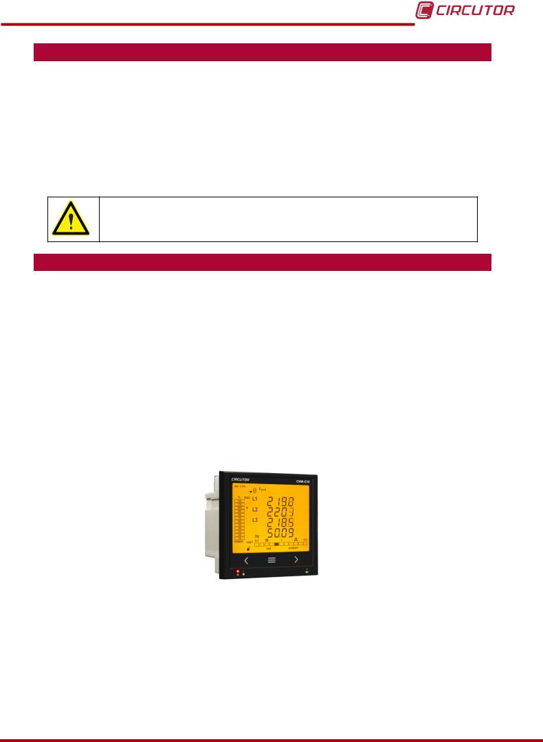
CVM-C10
1.- VERIFICATION UPON RECEPTION
Check the following points when you receive the unit:
a)The unit meets the specifications described in your order.
b)The unit has not suffered any damage during transport.
c)Perform an external visual inspection of the unit prior to switching it on.
d)Check that it has been delivered with the following:
—An installation guide,
—2 Retainers used to attach the unit,
—5 connectors.
If any problem is noticed upon reception, immediately contact the transport company and/or CIRCUTOR’s after-sales service.
2.- PRODUCT DESCRIPTION
The CVM-C10 unit measures, calculates and displays the main electrical parameters of the following networks: single-phase, two-phase, with and without neutral, balanced three-phase, with ARON measurements or unbalanced. The measurement will be taken in RMS with the three AC voltage inputs and three current inputs.
There are 3 versions of the unit, depending on the type of current input:
CVM-C10-ITF, indirect current measurement with /5A or /1A transformers.
CVM-C10-ITF-IN, indirect current measurement with /5A or /1A transformers and an input to measure the neutral current.
CVM-C10-MC, indirect current measurement with efficient transformers of the
MC1 and MC3 series.
CVM-C10-mV indirect current measurement with /0.333V transformers.
The unit features:
—3 keys that allow you to browse between the various screens and program the unit.
—3 indicator LEDs: CPU, ALARM and KEY.
—LCD display, displays all parameters,
—2 digital inputs, used to select the tariff or detect the logic state of external signals.
—2 digital outputs, fully programmable.
(Not available in the CVM-C10-ITF-IN model)
—2 alarm relays, fully programmable.
—RS-485 Communications, with two serial protocols: MODBUS RTU© and BACnet.
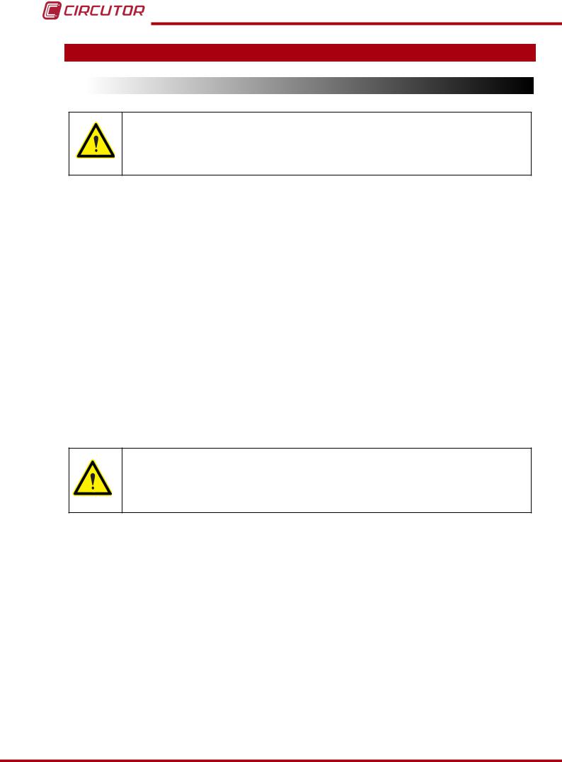
CVM-C10
3.- UNIT INSTALLATION
3.1.- PRIOR RECOMMENDATIONS
In order to use the unit safely, it is critical that individuals who handle it follow the safety measures set out in the standards of the country where it is being used, use the necessary personal protective equipment, and pay attention to the various warnings indicated in this instruction manual.
The CVM-C10 unit must be installed by authorised and qualified staff.
The power supply plug must be disconnected and measuring systems switched off before handling, altering the connections or replacing the unit. It is dangerous to handle the unit while it is powered.
Also, it is critical to keep the cables in perfect condition in order to avoid accidents, personal injury and damage to installations.
The manufacturer of the unit is not responsible for any damage resulting from failure by the user or installer to heed the warnings and/or recommendations set out in this manual, nor for damage resulting from the use of non-original products or accessories or those made by other manufacturers.
If an anomaly or malfunction is detected in the unit, do not use it to take any measurements.
Inspect the work area before taking any measurements. Do not take measurements in dangerous areas or where there is a risk of explosion.
Disconnect the unit from the power supply (unit and measuring system power supply) before maintaining, repairing or handling the unit’s connections.
Please contact the after-sales service if you suspect that there is an operational fault in the unit.

CVM-C10
3.2.- INSTALLATION
The unit will be installed on a panel (92+0.8 x 92+0.8 mm panel drill hole, in compliance with DIN
43700). All connections are located inside the electric panel.
Terminals, opening covers or removing elements can expose parts that are hazardous to the touch while the unit is powered. Do not use the unit until it is fully installed.
The unit must be connected to a power circuit that is protected with gl (IEC 269) or M type fuses with a rating of 0.5 to 2A. It must be fitted with a circuit breaker or equivalent device, in order to be able to disconnect the unit from the power supply network.
The power and voltage measuring circuit must be connected with cables that have a minimum cross-section of 1mm2.
The secondary line of the current transformer will have a minimum cross-section of 2.5 mm2.

CVM-C10
3.3.- UNIT TERMINALS
3.3.1.- List of terminals, CVM-C10-ITF, CVM-C10-MC and CVM-C10-mV models
Table 2:List of terminals of the CVM-C10-ITF, CVM-C10-MC and CVM-C10-mV.
|
Unit terminals |
||
|
1 : A1 Auxiliary power supply. |
13: I2, digital input 2 / tariff selection |
|
|
2: A2 Auxiliary power supply. |
14: VL1, Voltage input L1 |
|
|
3: Rc, Common relay output |
15: VL2, Voltage input L2 |
|
|
4: R2, Relay output 2 |
16: VL3,Voltage input L3 |
|
|
5: R1, Relay output 1 |
17: N, Neutral |
|
|
6: CT, Common digital output. |
18: S1 , Current input L1 |
|
|
7: T2, Digital output 2 |
19: S2, Current input L1 |
|
|
8: T1, Digital output 1 |
20: S1, Current input L2 |
|
|
9: A(+), RS485 |
21: S2, Current input L2 |
|
|
10: B(-), RS485 |
22: S1, Current input L3 |
|
|
11: GND, for RS485 and digital inputs |
23: S2, Current input L3 |
|
|
12: I1, digital input 1 / tariff selection |
||
|
2 |
3 |
4 |
5 |
6 |
7 |
8 |
9 |
10 |
11 |
12 |
||||||
|
1 |
13 |
|||||||||||||||
|
OUTPUTS |
S0+ |
|||||||||||||||
|
S0S0+ |
RS485 |
INPUTS |
||||||||||||||
|
POWER SUPPLY |
Rc R2 R1 |
Tc T2 |
T1 |
A(+) B(-) |
I1 |
I2 |
||||||||||
|
GND |
||||||||||||||||
|
Ph-Ph |
Ph-N |
|||||||||||||||
|
520V ~ |
300V |
~ |
P1 |
L1 |
P2 P1 |
P2 P1 |
P2 |
|||||||||
|
VL1 |
VL2 |
VL3 |
N |
L2 |
L3 |
|||||||||||
|
S1 |
S2 |
S1 |
S2 |
S1 |
S2 |
|||||||||||
|
14 |
15 |
16 |
17 |
18 |
19 |
20 |
21 |
22 |
23 |
Figure 1:Terminals of the CVM-C10-ITF, CVM-C10-MC and CVM-C10-mV.
![]()
CVM-C10
3.3.2.- List of terminals, CVM-C10-ITF-IN models.
Table 3:List of terminals of the CVM-C10-ITF-IN.
|
Unit terminals |
||
|
1 : A1 Auxiliary power supply. |
13: I2, digital input 2 / tariff selection |
|
|
2: A2 Auxiliary power supply. |
14: VL1, Voltage input L1 |
|
|
3: Rc, Common relay output |
15: VL2, Voltage input L2 |
|
|
4: R2, Relay output 2 |
16: VL3,Voltage input L3 |
|
|
5: R1, Relay output 1 |
17: N, Neutral |
|
|
6: Not connected |
18: S1 , Current input L1 |
|
|
7: S2, Neutral current input |
19: S2, Current input L1 |
|
|
8: S1, Neutral current input |
20: S1, Current input L2 |
|
|
9: A(+), RS485 |
21: S2, Current input L2 |
|
|
10: B(-), RS485 |
22: S1, Current input L3 |
|
|
11: GND, for RS485 and digital inputs |
23: S2, Current input L3 |
|
|
12: I1, digital input 1 / tariff selection |
||
|
2 |
3 |
4 |
5 |
6 |
7 |
8 |
9 |
10 |
11 |
12 |
||||||
|
1 |
13 |
|||||||||||||||
|
OUTPUTS |
||||||||||||||||
|
RS485 |
INPUTS |
|||||||||||||||
|
POWER SUPPLY |
Rc R2 R1 |
S2 |
S1 |
A(+) B(-) |
I1 |
I2 |
||||||||||
|
LN |
GND |
|||||||||||||||
|
P2 |
P1 |
|||||||||||||||
|
Ph-Ph |
Ph-N |
|||||||||||||||
|
520V ~ |
300V |
~ |
P1 |
L1 |
P2 P1 |
P2 P1 |
P2 |
|||||||||
|
VL1 |
VL2 |
VL3 |
N |
L2 |
L3 |
|||||||||||
|
S1 |
S2 |
S1 |
S2 |
S1 |
S2 |
|||||||||||
|
14 |
15 |
16 |
17 |
18 |
19 |
20 |
21 |
22 |
23 |
Figure 2:Terminals of the CVM-C10-ITF-IN.
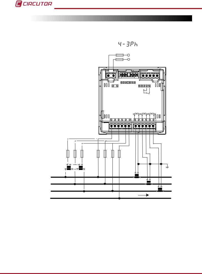
CVM-C10
3.4.- CONNECTION DIAGRAM
3.4.1.- Measuring Three-Phase Networks with a 4-wire connection, CVM-C10-ITF and CVM-C10-mV model.
|
Measurement system: |
||||||||||||||||
|
Power |
||||||||||||||||
|
Supply |
||||||||||||||||
|
OUTPUTS |
S0+ |
|||||||||||||||
|
S0S0+ |
RS485 |
INPUTS |
||||||||||||||
|
POWER SUPPLY |
Rc R2 R1 |
Tc T2 |
T1 |
A(+) B(-) |
I1 I2 |
|||||||||||
|
GND |
||||||||||||||||
|
Ph-Ph |
Ph-N |
|||||||||||||||
|
520V ~ |
300V |
~ |
P1 |
L1 |
P2 P1 |
L2 |
P2 P1 |
P2 |
||||||||
|
VL1 |
VL2 |
VL3 |
N |
L3 |
||||||||||||
|
S1 |
S2 |
S1 |
S2 |
S1 |
S2 |
|||||||||||
|
VL1 |
VL2 |
VL3 |
||||||||||||||
|
VL1 |
VL2 |
VL3 |
N |
|||||||||||||
|
a |
b |
a |
||||||||||||||
|
b |
||||||||||||||||
|
A |
B |
A |
B |
|||||||||||||
|
L1 |
S1 |
S2 |
||||||||||||||
|
P1 |
P2 |
|||||||||||||||
|
S1 |
S2 |
|||||||||||||||
|
L2 |
P1 |
P2 S1 |
||||||||||||||
|
S2 |
||||||||||||||||
|
L3 |
P1 |
P2 |
||||||||||||||
|
LOAD |
||||||||||||||||
N
Figure 3: Three-Phase measuring with a 4-wire connection, CVM-C10-ITF and CVM-C10-mV model.
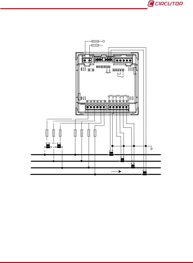
CVM-C10
3.4.2.- Measuring Three-Phase Networks with a 4-wire connection, CVM-C10-ITF-IN model.
Measurement system:
Power
 Supply
|
OUTPUTS |
||||||||||||||||||
|
RS485 |
INPUTS |
|||||||||||||||||
|
POWER SUPPLY |
Rc R2 R1 |
S2 LN |
S1 |
A(+) B(-) |
I1 I2 |
|||||||||||||
|
GND |
||||||||||||||||||
|
P2 |
P1 |
|||||||||||||||||
|
Ph-Ph |
Ph-N |
|||||||||||||||||
|
520V ~ |
300V |
~ |
P1 |
L1 |
P2 P1 |
L2 |
P2 P1 |
P2 |
||||||||||
|
VL1 |
VL2 |
VL3 |
N |
L3 |
||||||||||||||
|
S1 |
S2 |
S1 |
S2 |
S1 |
S2 |
|||||||||||||
|
VL1 |
VL2 |
VL3 |
||||||||||||||||
|
VL1 |
VL2 |
VL3 |
N |
|||||||||||||||
|
a |
b |
a |
b |
|||||||||||||||
|
A |
B |
A |
B |
S1 |
S2 |
|||||||||||||
|
L1 |
P1 |
P2 |
||||||||||||||||
|
S1 |
S2 |
|||||||||||||||||
|
L2 |
P1 |
P2 S1 |
||||||||||||||||
|
S2 |
||||||||||||||||||
|
L3 |
P1 |
P2 |
||||||||||||||||
|
LOAD |
S1 |
S2 |
||||||||||||||||
|
N |
||||||||||||||||||
|
P1 |
P2 |
|||||||||||||||||
Figure 4: Three-Phase Measuring with a 4-wire connection, CVM-C10-ITF-IN model.
CVM-C10
3.4.3.- Measuring Three-Phase Networks with a 4-wire connection, CVM-C10-MC model.
Measurement system:
|
Power |
||||||||||||||||
|
Supply |
||||||||||||||||
|
OUTPUTS |
S0+ |
|||||||||||||||
|
S0S0+ |
RS485 |
INPUTS |
||||||||||||||
|
POWER SUPPLY |
Rc R2 R1 |
Tc T2 |
T1 |
A(+) B(-) |
I1 |
I2 |
||||||||||
|
GND |
||||||||||||||||
|
Ph-Ph |
Ph-N |
|||||||||||||||
|
520V ~ |
300V |
~ |
P1 |
L1 |
P2 P1 |
L2 |
P2 P1 |
P2 |
||||||||
|
VL1 |
VL2 |
VL3 |
N |
L3 |
||||||||||||
|
S1 |
S2 |
S1 |
S2 |
S1 |
S2 |
|||||||||||
|
VL1 |
VL2 |
VL3 |
Grey/Pink |
Green/White |
Red/Blue |
Brown/Green |
||||||||||
|
VL1 |
VL2 |
VL3 |
N |
|||||||||||||
|
a |
b |
a |
b |
|||||||||||||
|
A |
B |
A |
B |
|||||||||||||
|
L1 |
1P1 |
1P2 |
||||||||||||||
|
L2 |
2P1 |
2P2 |
||||||||||||||
|
L3 |
3P1 |
3P2 |
||||||||||||||
|
N |
LOAD |
|||||||||||||||
Figure 5: Three-Phase measuring with a 4-wire connection, CVM-C10-MC model.
The MC transformer secondary value is set to 0.250 A (fixed value)
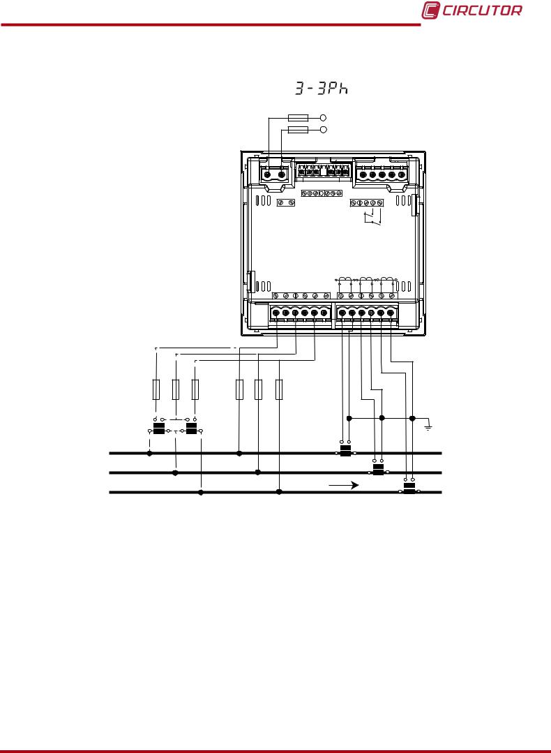
CVM-C10
3.4.4.- Measuring Three-Phase Networks with a 3-wire connection, CVM-C10-ITF and CVM-C10-mV model.
|
Measurement system: |
|||||||||||||||||
|
Power |
|||||||||||||||||
|
Supply |
|||||||||||||||||
|
OUTPUTS |
S0+ |
||||||||||||||||
|
S0S0+ |
RS485 |
INPUTS |
|||||||||||||||
|
POWER SUPPLY |
Rc R2 R1 |
Tc T2 |
T1 |
A(+) B(-) |
I1 I2 |
||||||||||||
|
GND |
|||||||||||||||||
|
Ph-Ph |
Ph-N |
||||||||||||||||
|
520V ~ |
300V |
~ |
P1 |
L1 |
P2 P1 |
L2 |
P2 P1 |
P2 |
|||||||||
|
VL1 |
VL2 |
VL3 |
N |
L3 |
|||||||||||||
|
S1 |
S2 |
S1 |
S2 |
S1 |
S2 |
||||||||||||
|
VL1 |
VL2 |
VL3 |
|||||||||||||||
|
VL1 |
VL2 |
VL3 |
|||||||||||||||
|
a |
b |
a |
b |
||||||||||||||
|
A |
B |
A |
B |
S1 |
S2 |
||||||||||||
|
L1 |
P1 |
P2 |
|||||||||||||||
|
S1 |
S2 |
||||||||||||||||
|
L2 |
P1 |
P2 S1 |
S2 |
||||||||||||||
|
LOAD |
|||||||||||||||||
|
L3 |
|||||||||||||||||
|
P1 |
P2 |
||||||||||||||||
Figure 6: Three-Phase measuring with a 3-wire connection, CVM-C10-ITF and CVM-C10-mV model.
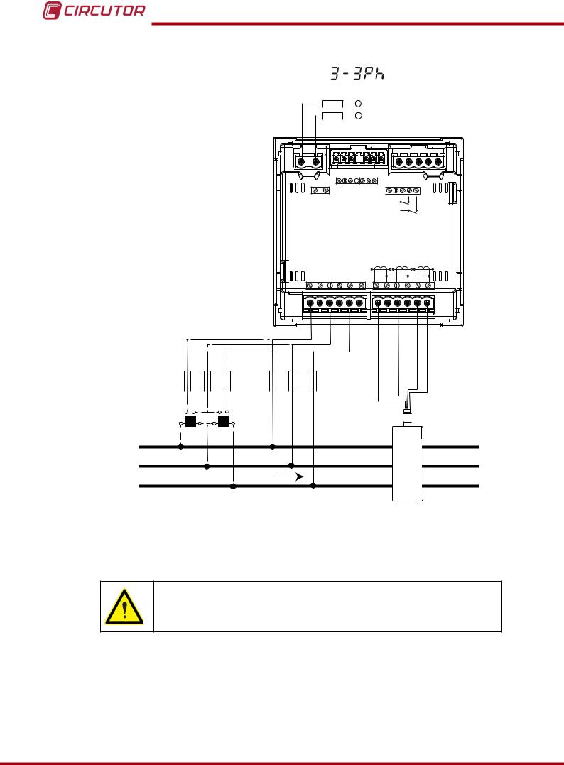
CVM-C10
3.4.5.- Measuring Three-Phase Networks with a 3-wire connection, CVM-C10-MC model.
|
Measurement system: |
|||||||||||||||
|
Power |
|||||||||||||||
|
Supply |
|||||||||||||||
|
OUTPUTS |
S0+ |
||||||||||||||
|
S0S0+ |
RS485 |
INPUTS |
|||||||||||||
|
POWER SUPPLY |
Rc R2 R1 |
Tc T2 |
T1 |
A(+) B(-) |
I1 I2 |
||||||||||
|
GND |
|||||||||||||||
|
Ph-Ph |
Ph-N |
||||||||||||||
|
520V ~ |
300V |
~ |
P1 |
L1 |
P2 P1 |
L2 |
P2 P1 |
P2 |
|||||||
|
VL1 |
VL2 |
VL3 |
N |
L3 |
|||||||||||
|
S1 |
S2 |
S1 |
S2 |
S1 |
S2 |
||||||||||
|
VL1 |
VL2 |
VL1 |
VL2 |
VL3 |
N |
Grey/Pink |
Green/White |
Red/Blue |
Brown/Green |
||||||
|
VL3 |
|||||||||||||||
|
a |
b |
a |
|||||||||||||
|
b |
|||||||||||||||
|
A |
B |
A |
B |
||||||||||||
|
L1 |
1P1 |
1P2 |
|||||||||||||
|
L2 |
2P1 |
2P2 |
|||||||||||||
|
L3 |
LOAD |
3P1 |
3P2 |
||||||||||||
Figure 7: Three-Phase measuring with a 3-wire connection, CVM-C10-MC model.
The MC transformer secondary value is set to 0.250 A (fixed value)
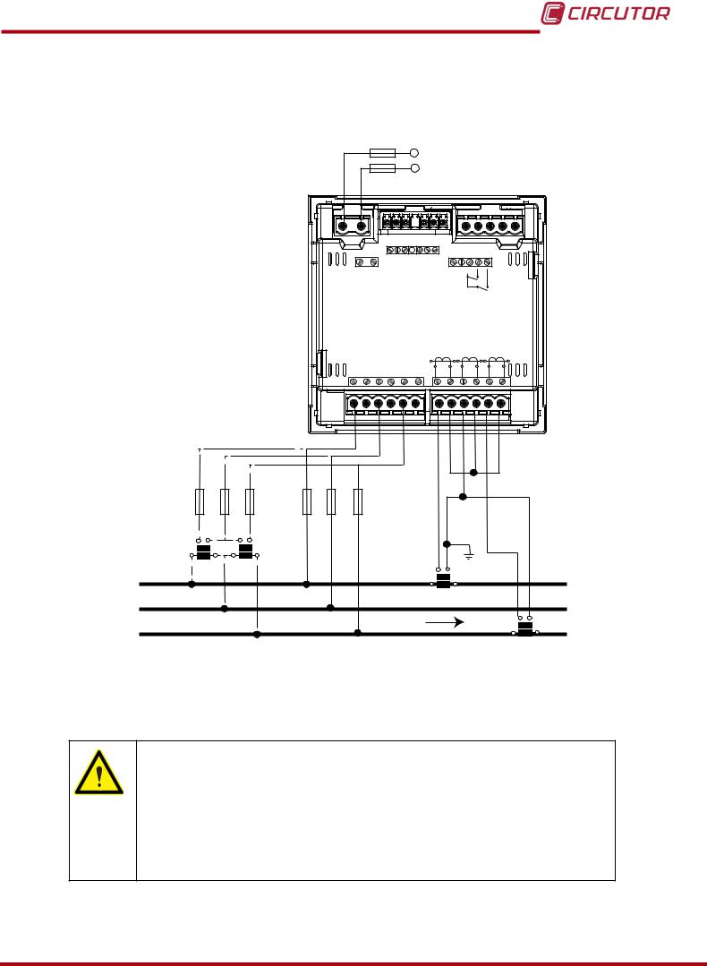
CVM-C10
3.4.6.- Measuring Three-Phase Networks with a 3-wire connection and transformers with an ARON connection, CVM-C10-ITF, CVM-C10-MC and CVM-C10-mV models.
Measurement system:
|
Power |
|||||||||
|
Supply |
|||||||||
|
OUTPUTS |
S0+ |
||||||||
|
S0S0+ |
RS485 |
INPUTS |
|||||||
|
POWER SUPPLY |
Rc R2 R1 |
Tc T2 |
T1 |
A(+) B(-) |
I1 I2 |
||||
|
GND |
|||||||||
|
Ph-Ph |
Ph-N |
||||||||
|
520V ~ |
300V |
~ |
P1 |
L1 |
P2 P1 |
L2 |
P2 P1 |
P2 |
|
|
VL1 |
VL2 |
VL3 |
N |
L3 |
|||||
|
S1 |
S2 |
S1 |
S2 |
S1 |
S2 |
|
VL1 |
VL2 |
VL3 |
|||||
|
VL1 |
VL2 |
VL3 |
|||||
|
a |
b |
a |
b |
||||
|
A |
B |
A |
B |
S1 |
|||
|
L1 |
S2 |
||||||
|
P1 |
P2 |
||||||
|
L2 |
S1 |
S2 |
|||||
|
LOAD |
|||||||
|
L3 |
|||||||
|
P1 |
P2 |
Figure 8: Three-Phase measuring with a 3-wire connection and transformers with an ARON connection, CVM-C10- ITF, CVM-C10-MC and CVM-C10-mV models.
CVM-C10-ITF model:
The transformer secondary value must be 5A or 1A
CVM-C10-MC model:
The MC transformer secondary value is set to 0.250 A (fixed value)
CVM-C10-mV model:
The transformer secondary value must be 0.333 V
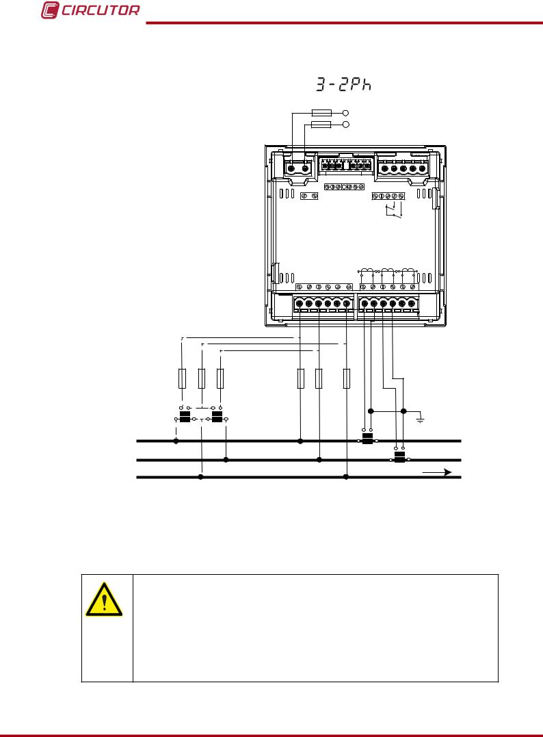
CVM-C10
3.4.7.- Measuring Two-Phase Networks with a 3-wire connection, CVM-C10-ITF, CVM-C10-MC and CVM-C10-mV models.
|
Measurement system: |
|||||||||||||
|
Power |
|||||||||||||
|
Supply |
|||||||||||||
|
OUTPUTS |
S0+ |
||||||||||||
|
S0S0+ |
RS485 |
INPUTS |
|||||||||||
|
POWER SUPPLY |
Rc R2 R1 |
Tc T2 |
T1 |
A(+) B(-) |
I1 I2 |
||||||||
|
GND |
|||||||||||||
|
Ph-Ph |
Ph-N |
||||||||||||
|
520V ~ |
300V |
~ |
P1 |
L1 |
P2 P1 |
L2 |
P2 P1 |
P2 |
|||||
|
VL1 |
VL2 |
VL3 |
N |
L3 |
|||||||||
|
S1 |
S2 |
S1 |
S2 |
S1 |
S2 |
||||||||
|
VL1 |
N |
VL2 |
|||||||||||
|
VL1 |
VL2 |
N |
|||||||||||
|
a |
b |
a |
b |
||||||||||
|
A |
B |
A |
B |
S1 |
S2 |
||||||||
|
L1 |
P1 |
P2 |
|||||||||||
|
S1 |
S2 |
||||||||||||
|
L2 |
P1 |
P2 |
|||||||||||
|
N |
LOAD |
||||||||||||
Figure 9: Measuring Two-Phase Networks with a 3-wire connection, CVM-C10-ITF, CVM-C10-MC and CVM-C10-mV models.
CVM-C10-ITF model:
The transformer secondary value must be 5A or 1A
CVM-C10-MC model:
The MC transformer secondary value is set to 0.250 A (fixed value)
CVM-C10-mV model:
The transformer secondary value must be 0.333 V
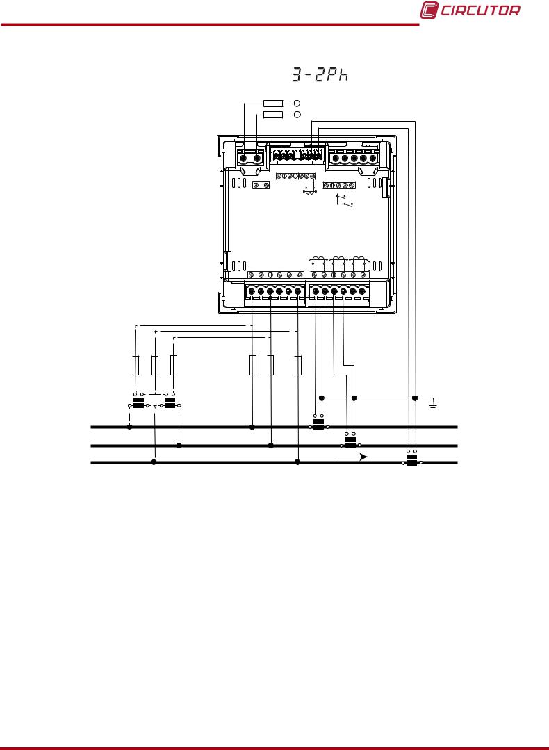
CVM-C10
3.4.8.- Measuring Two-Phase Networks with a 3-wire connection, CVM-C10-ITF-IN model.
|
Measurement system: |
|||||||||||||||
|
Power |
|||||||||||||||
|
Supply |
|||||||||||||||
|
OUTPUTS |
|||||||||||||||
|
RS485 |
INPUTS |
||||||||||||||
|
POWER SUPPLY |
Rc R2 R1 |
S2 LN |
S1 |
A(+) B(-) |
I1 I2 |
||||||||||
|
GND |
|||||||||||||||
|
P2 |
P1 |
||||||||||||||
|
Ph-Ph |
Ph-N |
||||||||||||||
|
520V ~ |
300V |
~ |
P1 |
L1 |
P2 P1 |
L2 |
P2 P1 |
P2 |
|||||||
|
VL1 |
VL2 |
VL3 |
N |
L3 |
|||||||||||
|
S1 |
S2 |
S1 |
S2 |
S1 |
S2 |
||||||||||
|
VL1 |
N |
VL2 |
|||||||||||||
|
VL1 |
VL2 |
N |
|||||||||||||
|
a |
b |
a |
|||||||||||||
|
b |
|||||||||||||||
|
A |
B |
A |
B |
S1 |
|||||||||||
|
S2 |
|||||||||||||||
|
L1 |
P1 |
P2 |
|||||||||||||
|
S1 |
S2 |
||||||||||||||
|
L2 |
P1 |
P2 |
|||||||||||||
|
LOAD |
S1 |
S2 |
|||||||||||||
|
N |
|||||||||||||||
|
P1 |
P2 |
||||||||||||||
Figure 10: Measuring Two-Phase Networks with a 3-wire connection, CVM-C10-ITF-IN model.
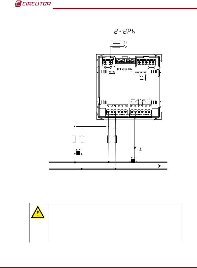
CVM-C10
3.4.9.- Measuring Single-Phase Networks, phase to phase, with a 2-wire connection, CVM-C10-ITF, CVM-C10-MC and CVM-C10-mV models.
|
Measurement system: |
|||||||||||
|
Power |
|||||||||||
|
Supply |
|||||||||||
|
OUTPUTS |
S0+ |
||||||||||
|
S0S0+ |
RS485 |
INPUTS |
|||||||||
|
POWER SUPPLY |
Rc R2 R1 |
Tc T2 |
T1 |
A(+) B(-) |
I1 I2 |
||||||
|
GND |
|||||||||||
|
Ph-Ph |
Ph-N |
||||||||||
|
520V ~ |
300V |
~ |
P1 |
L1 |
P2 P1 |
L2 |
P2 P1 |
P2 |
|||
|
VL1 |
VL2 |
VL3 |
N |
L3 |
|||||||
|
S1 |
S2 |
S1 |
S2 |
S1 |
S2 |
||||||
|
VL1 |
VL2 |
||||||||||
|
VL1 |
VL2 |
||||||||||
|
a |
b |
||||||||||
|
A |
B |
||||||||||
|
S1 |
S2 |
||||||||||
|
L1 |
P1 |
P2 |
|||||||||
|
L2 |
LOAD |
||||||||||
Figure 11: Measuring Single-Phase Networks, phase to phase, with a 2-wire connection, CVM-C10-ITF, CVM-C10-MC and CVM-C10-mV models.
CVM-C10-ITF model:
The transformer secondary value must be 5A or 1A
CVM-C10-MC model:
The MC transformer secondary value is set to 0.250 A (fixed value)
CVM-C10-mV model:
The transformer secondary value must be 0.333 V
![]()
CVM-C10
3.4.10.- Measuring Single-Phase Networks, phase to neutral, with a 2-wire connection, CVM-C10-ITF, CVM-C10-MC and CVM-C10-mV models.
|
Measurement system: |
|||||||||||
|
Power |
|||||||||||
|
Supply |
|||||||||||
|
OUTPUTS |
S0+ |
||||||||||
|
S0S0+ |
RS485 |
INPUTS |
|||||||||
|
POWER SUPPLY |
Rc R2 R1 |
Tc T2 |
T1 |
A(+) B(-) |
I1 I2 |
||||||
|
GND |
|||||||||||
|
Ph-Ph |
Ph-N |
||||||||||
|
520V ~ |
300V |
~ |
P1 |
L1 |
P2 P1 |
L2 |
P2 P1 |
P2 |
|||
|
VL1 |
VL2 |
VL3 |
N |
L3 |
|||||||
|
S1 |
S2 |
S1 |
S2 |
S1 |
S2 |
||||||
|
VL1 |
N |
||||||||||
|
VL1 |
N |
||||||||||
|
a |
b |
||||||||||
|
A |
B |
S1 |
|||||||||
|
S2 |
|||||||||||
|
L1 |
P1 |
P2 |
|||||||||
|
LOAD |
|||||||||||
N
Figure 12: Measuring Single-Phase Networks, phase to neutral, with a 2-wire connection, CVM-C10-ITF, CVM-C10-MC and CVM-C10-mV models.
CVM-C10-ITF model:
The transformer secondary value must be 5A or 1A
CVM-C10-MC model:
The MC transformer secondary value is set to 0.250 A (fixed value)
CVM-C10-mV model:
The transformer secondary value must be 0.333 V
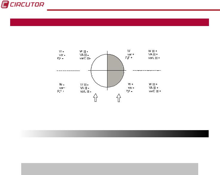
CVM-C10
4.- OPERATION
The CVM-C10 is a four-quadrant power analyzer (consumption and generation).
|
Single-phase |
Three-phase |
90º |
Single-phase |
Three-phase |
|
|
k |
k |
k |
k |
||
|
k |
k |
k |
k |
||
|
k |
k |
||||
|
Capacitive |
Inductive |
||||
|
Inductive |
180º |
0º |
|||
|
Capacitive |
|||||
|
Single-phase Three-phase |
Single-phase Three-phase |
||||
|
k |
k |
k |
k |
||
|
k |
k |
k |
k |
||
|
k |
-90º |
k |
|||
Generation Consumption
Power Power
Figure 13: Four quadrants of CVM-C10
4.1.- MEASURING PARAMETERS
The unit displays the electrical parameters shown in Table 4.
Table 4: Measuring parameters of the CVM-C10.
|
Parameter |
Units |
Phases |
Total |
N |
||
|
L1-L2-L3 |
III |
|||||
|
Phase-neutral voltage |
Vph-N |
|
||||
|
Phase-phase voltage |
Vph-ph |
|
|
|||
|
Current |
A |
|
|
|
||
|
Frequency |
Hz |
|
|
|||
|
Active power |
M/kW |
|
|
|||
|
Apparent power |
M/kVA |
|
|
|||
|
Total Reactive Power |
M/kvar |
|
|
|||
|
Total Reactive Power — Consumption |
M/kvar |
|
|
|||
|
Total Reactive Power — Generation |
M/kvar |
|
|
|||
|
Total Inductive Reactive Power |
M/kvarL |
|
|
|||
|
Inductive Reactive Power — Consumption |
M/kvarL |
|
|
|||
|
Inductive Reactive Power — Generation |
M/kvarL |
|
|
|||
|
Total Capacitive Reactive Power |
M/kvarC |
|
|
|||
|
Capacitive Reactive Power — Consumption |
M/kvarC |
|
|
|||
|
Capacitive Reactive Power — Generation |
M/kvarC |
|
|
|||
|
Power factor |
PF |
|
|
|||
|
Cos φ |
φ |
|
|
|||
|
THD % Voltage |
% THD V |
|
||||
|
THD % Current |
% THD A |
|
||||
|
Harmonic Breakdown — Voltage |
harm V |
|
||||
|
(up to the 31st order harmonic) |
||||||
|
22 |
Instruction Manual |

CVM-C10
Table 4 ( Continuation ) : Measuring parameters of the CVM-C10.
|
Parameter |
Units |
Phases |
Total |
N |
|
|
L1-L2-L3 |
III |
||||
|
Harmonic Breakdown — Current |
harm V |
|
|||
|
(up to the 31st order harmonic) |
|||||
|
Total Active Energy |
M/kWh |
|
|||
|
Total Inductive Reactive Energy |
M/kvarLh |
|
|||
|
Total Capacitive Reactive Energy |
M/kvarCh |
|
|||
|
Total Apparent Energy |
M/kVAh |
|
|||
|
Active Energy Tariff 1 |
M/kWh |
|
|||
|
Inductive Reactive Energy Tariff 1 |
M/kvarLh |
|
|||
|
Capacitive Reactive Energy Tariff 1 |
M/kvarCh |
|
|||
|
Apparent Energy Tariff 1 |
M/kVAh |
|
|||
|
Active Energy Tariff 2 |
M/kWh |
|
|||
|
Inductive Reactive Energy Tariff 2 |
M/kvarLh |
|
|||
|
Capacitive Reactive Energy Tariff 2 |
M/kvarCh |
|
|||
|
Apparent Energy Tariff 2 |
M/kVAh |
|
|||
|
Active Energy Tariff 3 |
M/kWh |
|
|||
|
Inductive Reactive Energy Tariff 3 |
M/kvarLh |
|
|||
|
Capacitive Reactive Energy Tariff 3 |
M/kvarCh |
|
|||
|
Apparent Energy Tariff 3 |
M/kVAh |
|
|||
|
Maximum Current Demand |
A |
|
|
||
|
Maximum Demand of Active power |
M/kW |
|
|
||
|
Maximum Demand of Apparent Power |
M/kVA |
|
|
||
|
Parameter |
Units |
Tariff: T1-T2-T3 |
Total |
||
|
No. of hours |
hours |
|
|
||
|
Cost |
COST |
|
|
||
|
CO2 Emissions |
kgCO2 |
|
|
4.2.- KEYBOARD FUNCTIONS
The CVM-C10 has 3 keys that allow you to browse between the various screens and program the unit.
Key functions on measuring screens (Table 5):
Table 5: Key functions on measuring screens.
|
Key |
Short keystroke |
Long keystroke |
|
|
(2 s) |
|||
|
Previous screen |
Display of minimum value |
||
|
Next screen |
Display of maximum value |
||
|
Browsing the different profiles |
Accessing the programming menu |
||
|
(analyzer, user, e3) |
|||
CVM-C10
Table 5 (Continuation ) : Key functions on measuring screens.
|
Key |
Short keystroke |
Long keystroke |
|
|
(2 s) |
|||
|
Display of the Maximum Demand |
|||
|
Active alarm information |
|||
|
Unlocks the active alarm |
|||
Key functions on harmonics screens (Table 6):
|
Table 6: Key functions on harmonics screens. |
|||
|
Key |
Short keystroke |
Long keystroke |
|
|
(2 s) |
|||
|
Output of the harmonics screens |
|||
|
Next screen |
|||
|
Browsing the different types of har- |
Accessing the programming |
||
|
monics |
menu |
Key functions on the programming menu, query mode (Table 7):
Table 7: Key functions on the programming menu, query mode.
|
Key |
Short keystroke |
Long keystroke |
|
|
(2 s) |
|||
|
Previous screen |
Programming output |
||
|
Next screen |
Programming output |
||
|
Opening the programming menu in the edit |
|||
|
mode |
Key functions on the programming menu, edit mode (Table 8):
|
Table 8: Key functions on the programming menu, edit mode. |
|
|
Key |
Keystroke |
|
Next page |
|
|
Increases the digits (0-9) or rotates between the different options. |
|
|
Moves an editable digit (flashing) |
|
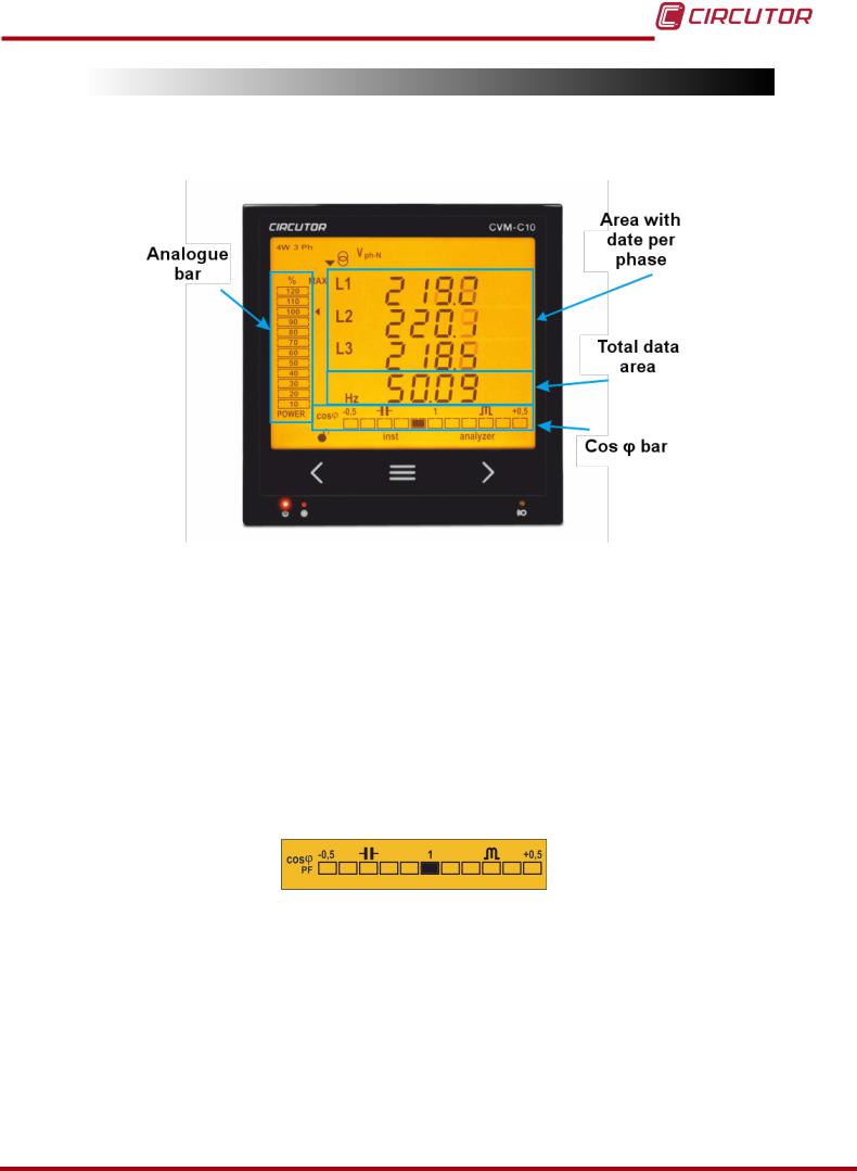
CVM-C10
4.3.- DISPLAY
The unit has a backlit LCD display showing all the parameters listed in Table 3.
The display is divided into four areas (Figure 14):
Figure 14: CVM-C10 Display areas
The area with data per phase displays the instantaneous, maximum and minimum values of each phase being measured or calculated by the unit.
The total data area displays the totals of the values being measured or calculated by the unit.
Analogue bar, displays the % of the current power of the installation.
Cos φ — PF Bar, displays the value of the system’s Cos φ or power factor in real time.
4.3.1. COS φ — PF (POWER FACTOR) BAR
Figure 15: Cos φ — PF Bar
This bar displays the value of the installation’s cos φ or power factor in real time.
The parameter that will be displayed is selected on the programming menu. ( “4.9.13. Selecting the Cos φ — PF bar on the display”)
-
manualzz.com
- Industrial & lab equipment
- Measuring, testing & control
Инструкции и Руководства для Circutor CVM-C10.
Мы нашли 22
инструкции доступные для бесплатного скачивания:
Инструкция по применению, Руководство пользователя, Техническая спецификация
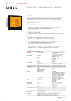
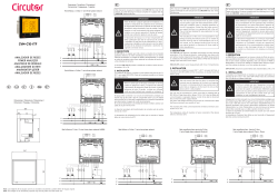
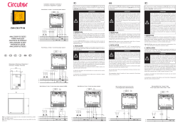
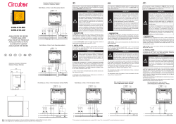
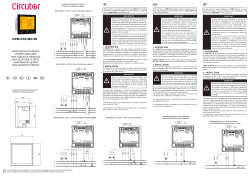
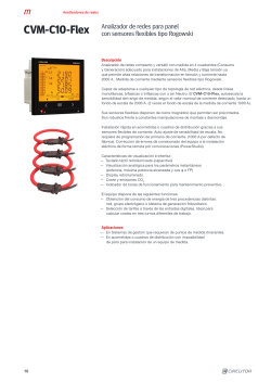
instruction manual
Бренд:
Circutor
Категория:
Measuring, testing & control
Размер:
2 MB
Страниц:
96
Язык(и):
Английский
Оглавление
-
3
SAFETY PRECAUTIONS
-
3
DISCLAIMER
-
4
CONTENTS
-
6
REVISION LOG
-
7
1�- VERIFICATION UPON RECEPTION
-
7
2�- PRODUCT DESCRIPTION
-
9
3�- UNIT INSTALLATION
-
9
3�1�- PRIOR RECOMMENDATIONS
-
10
3�2�- INSTALLATION
-
10
3�3�- CVM-C10-FLEX: ROGOWSKI SENSORS
-
12
3�4�- UNIT TERMINALS
-
12
3�4�1�- LIST OF TERMINALS, CVM-C10-ITF, CVM-C10-MC AND CVM-C10-mV MODELS
-
13
3�4�2�- LIST OF TERMINALS, CVM-C10-ITF-IN MODELS
-
14
3�4�3�- LIST OF TERMINALS, CVM-C10-FLEX MODEL
-
15
3�5�- CONNECTION DIAGRAM
-
15
CVM-C10-mV MODEL
-
16
MODEL
-
18
MODEL
-
19
CVM-C10-mV MODEL
-
20
MODEL
-
21
MODEL
-
22
MERS WITH AN ARON CONNECTION, CVM-C10-ITF AND CVM-C10-MC MODELS
-
23
CVM-C10-MC AND CVM-C10-mV MODELS
-
24
MODEL
-
26
TION, CVM-C10-ITF, CVM-C10-MC AND CVM-C10-mV MODELS
-
27
TION, CVM-C10-FLEX MODEL
-
28
NECTION, CVM-C10-ITF, CVM-C10-MC AND CVM-C10-mV MODELS
-
29
NECTION, CVM-C10-FLEX MODEL
-
30
4�- OPERATION
-
31
4�1�- MEASURING PARAMETERS
-
32
4�2�- KEYBOARD FUNCTIONS
-
34
4�3�- DISPLAY
-
34
— PF (POWER FACTOR) BAR
-
35
4�3�2� ANALOGUE BAR
-
35
4�3�3� OTHER SYMBOLS ON THE DISPLAY
-
36
4�4�- LED INDICATORS
-
36
OPERATION PROFILES
-
36
4�5�1� ANALYZER PROFILE
-
40
PROFILE
-
43
4�5�3� USER
-
43
HARMONICS
-
44
INPUTS
-
44
4�8�- OUTPUTS
-
45
4�9�- PROGRAMMING
-
46
4�9�1� PRIMARY VOLTAGE
-
47
4�9�2� SECONDARY VOLTAGE
-
47
4�9�3� PRIMARY CURRENT
-
48
4�9�4� SECONDARY CURRENT ( MODEL CVM-C10-ITF)
-
48
4�9�5� PRIMARY NEUTRAL CURRENT ( MODEL CVM-C10-ITF-IN)
-
49
4�9�6� SECUNDARY NEUTRAL CURRENT (MODEL CVM-C10-ITF-IN)
-
49
4�9�7� NUMBER OF QUADRANTS
-
49
4�9�8� MEASUREMENT CONVENTION
-
50
4�9�9� TYPE OF INSTALLATION
-
50
4�9�10� MAXIMUM DEMAND INTEGRATION PERIOD
-
51
4�9�11� DELETING MAXIMUM DEMAND
-
51
4�9�12� SELECTING THE OPERATION PROFILE
-
53
4�9�13� BACKLIGHT, TURNING ON THE BACKLIT DISPLAY
-
53
BAR ON THE DISPLAY
-
54
4�9�15� DELETING MAXIMUM AND MINIMUM VALUES
-
54
4�9�16� DELETING ENERGY VALUES
-
54
4�9�17� SELECTING THE RANGE OF ENERGIES
-
55
4�9�18� ACTIVATING THE HARMONICS DISPLAY SCREEN
-
55
CARBON EMISSION RATIO OF GENERATED ENERGY
-
56
CARBON EMISSION RATIO OF CONSUMED ENERGY
-
56
4�9�21� COST RATIO OF GENERATED ENERGY
-
57
4�9�22� COST RATIO OF CONSUMED ENERGY
-
58
4�9�23� PROGRAMMING ALARM 1 (RELAY 1)
-
63
4�9�24� PROGRAMMING ALARM 2 (RELAY 2)
-
63
4�9�25� PROGRAMMING ALARM 3 (DIGITAL OUTPUT T1)
-
65
4�9�26� PROGRAMMING ALARM 4 (DIGITAL OUTPUT T2)
-
66
4�9�27� OPERATING MODE OF DIGITAL INPUT
-
66
4�9�28� OPERATING MODE OF DIGITAL INPUT
-
66
4�9�29� RS-485 COMMUNICATIONS: PROTOCOL
-
70
4�9�30� LOCKING THE PROGRAMMING
-
72
4�10�- COMMUNICATIONS
-
72
4�10�1� CONNECTIONS
-
73
4�10�2� PROTOCOL
-
74
4�10�3� MODBUS COMMANDS
-
83
4�10�4� BACnet PROTOCOL
-
84
4�10�5� MAPA PICS
-
87
5�- TECHNICAL FEATURES
-
91
6�- MAINTENANCE AND TECHNICAL SERVICE
-
91
7�- GUARANTEE
-
92
8�- CE CERTIFICATE
Открыть в новой вкладке