Время на прочтение
6 мин
Количество просмотров 23K

Относительно недавно мы публиковали статью “Какой firewall лучше всех? Лидеры среди UTM и Enterprise Firewalls (Gartner 2017)”. Безусловно, подобные сравнения очень важны и интересно знать лидеров рынка. Эта информация весьма полезна при выборе решения. Но большинство инженеров/сисадминов обращают внимание на еще один момент — документация. Чем больше документации и чем больше интернет-сообщество, тем проще администрировать выбранное решение. Как же обстоят дела с этим у Check Point? Ниже мы приведем наиболее полезные ресурсы Check Point, где вы сможете найти всю необходимую документацию или ответ на какой-либо технический вопрос. Эти ресурсы будут особенно полезны тем, кто уже использует Check Point.
Начать хотелось бы с небольшого тезиса — Check Point это сложный и высокотехнологичный продукт. Связано это в первую очередь с тем, что он способен выполнять огромное количество функций. Как мы уже описывали ранее, функционал Check Point-а разделен на блейды: Firewall, IPSec VPN, Moblie Access, Application Control, URL Filtering, Data Loss Prevention, IPS, Anti-Bot, Anti-Virus, Threat Emulation, Threat Extraction, Anti-Spam, Identity Awareness, Content Awareness, QoS, Monitoring, Smart Event и т.д. Поэтому если вы ищите одну большую книжку по Check Point, то вы ее не найдете. Вместо этого вся документация Check Point разбита на несколько категорий. Распишем самые важные.
Check Point Support Center
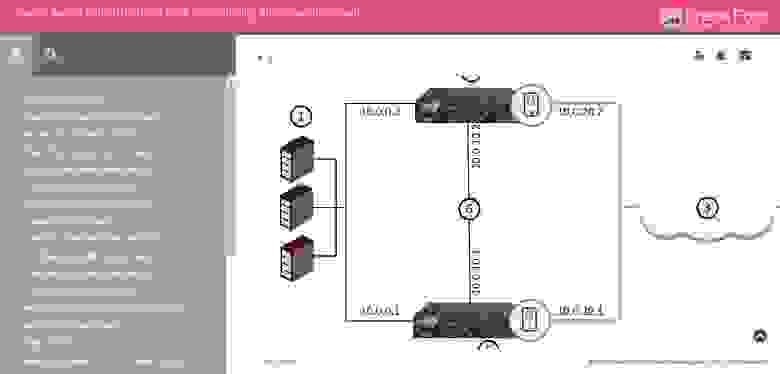
Это самый главный ресурс Check Point. И заходить сюда стоит не только когда вы хотите обратиться в техническую поддержку, но и когда ищите какую-либо документацию.

Как можно увидеть на картинке, любой поисковый запрос (в нашем случае IPS) выдает результаты в четырех разделах:
- SecureKnowledge (коротко их называют sk) — это глобальная база знаний Check Point. Здесь описываются практически все встречаемые проблемы, их симптомы, а самое главное — способы решения. Если у вас возникла проблема, то с вероятностью 98% уже существует sk, в котором описывается ее решение.
- Downloads — раздел загрузок. Здесь могут выкладывается хотфиксы (патчи) либо другие файлы доступные для скачивания (vpn-клиенты, скрипты и т.д.).
- Documentation — здесь отражается вся документация, связанная с вашим запросом. Как правило это PDF-файлы.
- CheckMates (Ранее Forums) — информация с форумов Check Point, связанная с вашим запросом.
В целом это очень мощный портал, которые содержит колоссальное количество информации о Check Point. Но вернемся к нашему вопросу с документацией. Что же искать?
Check Point Administration Guide
Название говорит само за себя. Думаю это первая документация с которой стоит начинать при возникновении проблем или вопросов связанных с Check Point. “Админ гайды” как правило делятся по блейдам и версиям операционной системы, например: R80.10 Mobile Access Administration Guide или R77 Mobile Access Administration Guide.
Подобные гайды содержат не только описание блейда, но и процедуру настройки. Поиск подобных гайдов естественно осуществляется через Support Center в разделе Documentation. При поиске указывайте название интересующего блейда и фразу “administration guide”. Примечательно, что начиная с версии R80.10 большинство документации доступно не только в виде pdf, но и в web-формате. Пример:
Кроме того, есть возможность скачать “сборник” админ гайдов по конкретной версии ПО. Например:
- R77 / R77.10 / R77.20 / R77.30 Administration Guides Package;
- R80.10 Administration Guides Package.
Данный “сборник” включает в себя огромное количество документации. Пример содержания “сборника” для R77:
Документация для R77
CP_CPView_R77_Guide.pdf
CP_R77.10_QoS_AdminGuide.pdf
CP_R77.20_EndpointSecurity_AdminGuide.pdf
CP_R77.30_Appendix_ReleaseNotes.pdf
CP_R77.30_ReleaseNotes.pdf
CP_R77_ApplicationControlURLFiltering_AdminGuide.pdf
CP_R77_CLI_ReferenceGuide.pdf
CP_R77_ClusterXL_AdminGuide.pdf
CP_R77_Compliance_AdminGuide.pdf
CP_R77_CPcodeDLP_ReferenceGuide.pdf
CP_R77_DataLossPrevention_AdminGuide.pdf
CP_R77_Firewall_AdminGuide.pdf
CP_R77_Gaia_AdminGuide.pdf
CP_R77_Gaia_Advanced_Routing_AdminGuide.pdf
CP_R77_Gaia_Installation_and_Upgrade_Guide.pdf
CP_R77_IdentityAwareness_AdminGuide.pdf
CP_R77_IPS_AdminGuide.pdf
CP_R77_MobileAccess_AdminGuide.pdf
CP_R77_Multi-DomainSecurityManagement_AdminGuide.pdf
CP_R77_Non_Gaia_Installation_and_Upgrade_Guide.pdf
CP_R77_PerformanceTuning_AdminGuide.pdf
CP_R77_QoS_AdminGuide.pdf
CP_R77_SecurePlatform_AdminGuide.pdf
CP_R77_SecurePlatform_AdvancedRoutingSuite_CLI.pdf
CP_R77_SecurityGatewayVE_NM_AdminGuide.pdf
CP_R77_SecurityGateway_TechAdminGuide.pdf
CP_R77_SecurityManagement_AdminGuide.pdf
CP_R77_SmartEvent_AdminGuide.pdf
CP_R77_SmartLog_AdminGuide.pdf
CP_R77_SmartProvisioning_AdminGuide.pdf
CP_R77_SmartReporter_AdminGuide.pdf
CP_R77_SmartViewMonitor_AdminGuide.pdf
CP_R77_SmartViewTracker_AdminGuide.pdf
CP_R77_SmartWorkflow_AdminGuide.pdf
CP_R77_ThreatPrevention_AdminGuide.pdf
CP_R77_VoIP_AdministrationGuide.pdf
CP_R77_VPN_AdminGuide.pdf
CP_R77_VSX_AdminGuide.pdf
Check Point Technical Reference Guides (ATRGs)
Бывают ситуации, когда информации в стандартных “админ гайдах” недостаточно. В этом случае стоит обратиться к документам с тегом “ATRG” — Advanced Technical Reference Guides. Как следует из названия, это более углубленные технические гайды, которые позволяют досконально разобраться в работе той или иной функции Check Point. Как и в случае с admin guide, искать ATRG документы можно в Support Center, дополнив запрос названием блейда, пример: atrg threat emulation.
Кроме того, совсем недавно появилась страничка, где приведены все ATRG гайды. Их уже более 35.
Check Point “How To” Guides
Помимо стандартных и расширенных (ATRG) гайдов существуют еще так называемые “How To”. Эти документы содержат инструкции по самым распространенным задачам, с которыми сталкиваются пользователи Check Point. Все гайды разбиты на категории:
Список всех “How To” можно найти в sk65385. Коллекция инструкций просто огромная. Рекомендую всегда держать их “под рукой”.
Check Point Processes and Daemons
Для того, чтобы эффективно решать встречающиеся проблемы с Check Point-ом, очень важно понимать, как он в принципе работает. Здесь на помощь приходит еще один SK — sk97638. Он описывает все процессы и “демоны” Check Point-а, включая такую информацию как:
- Описание процесса/демона;
- Где он располагается в файловой системе;
- Как называется и где находится его log-файл;
- Как его остановить;
- Как его запустить;
- Как запустить для него режим debug;
- И т.д.
Все это собрано в удобную таблицу, отражающую к какому блейду принадлежит “демон” и какие под-процессы он создает. Я бы отнес эту документацию к категории Must Have для любого администратора Check Point.
Какие порты использует Check Point?
Еще один весьма полезный документ Check Point — sk52421. Здесь вы найдете все порты, которые использует Check Point, с детальным описанием для чего и каким блейдом. Документ особенно пригодится, если Check Point находится за другим МЭ.
Оптимизация производительности Check Point (Best Practices)
В sk98348 вы найдете главные рекомендации по настройке и улучшению производительности таких вещей как: Security Gateway, ClusterXL, Cluster — 3rd party, VSX, CoreXL, SecureXL, Application Control, URL Filtering, Anti-Virus, Anti-Bot, IPS. Не стоит пренебрегать этими документами, особенно если ваш Check Point загружен более чем на 50%.
Check Point CheckMates
Последний ресурс, о котором я бы хотел рассказать, это CheckMates. Это комьюнити-портал огромного количества пользователей Check Point. Он так же поддерживается самим вендором. Здесь регулярно публикуются обучающие материалы, вебинары, интересные статьи от экспертов и многое другое. Но самое главное — здесь можно задать вопрос, на который вы не смогли найти ответ в документации (что мало вероятно). Сообщество весьма живое и скорее всего вам ответят очень быстро.
Английский vs Русский
К сожалению, почти вся представленная документация и ресурсы на английском языке (что весьма ожидаемо). Некоторую русскоязычную документацию можно найти на портале наших коллег из RRC, кое что в нашем блоге или ютуб-канале. Но естественно этого недостаточно. Здесь можно сделать только один вывод — без английского никуда. Что касается авторизованного обучения, то к счастью в России читают курсы на русском языке.
Заключение
Я постарался отразить ключевые документы и ресурсы Check Point (на самом деле их гораздо больше). Как можно заметить, вендор весьма ответственно подходит к вопросу и понимает всю его серьезность. Если же вы по какой-то причине не смогли найти нужный документ или решить свою проблему с Check Point, то можете смело обращаться к нам. Как говорится, «поможем, чем сможем». Спасибо за внимание!
- Manuals
- Brands
- Check Point Manuals
- Network Hardware
- 1500 Series
- Administration manual
-
Contents
-
Table of Contents
-
Troubleshooting
-
Bookmarks
Quick Links
21 April 2021
1500 APPLIANCE SERIES
R80.20.15
Centrally Managed
Administration Guide
Related Manuals for Check Point 1500 Series
Summary of Contents for Check Point 1500 Series
-
Page 1
21 April 2021 1500 APPLIANCE SERIES R80.20.15 Centrally Managed Administration Guide… -
Page 2
Check Point. While every precaution has been taken in the preparation of this book, Check Point assumes no responsibility for errors or omissions. This publication and features described herein are subject to change without notice. -
Page 3
Open the latest version of this Download the latest version of this document in PDF format Feedback Check Point is engaged in a continuous effort to improve its documentation. Please help us by sending your comments Revision History Date Description «Configuring MAC Filtering»… -
Page 4: Table Of Contents
Defining a Gateway Object Defining a Gateway Cluster Object Workflow Creating a Cluster for New Gateways Converting an Existing Check Point Appliance to a Cluster Viewing Cluster Status in the WebUI Creating the Security Policy Working with Security Zone Objects…
-
Page 5
Table of Contents VPN Properties Finish Updating the Corporate Office Gateway Creating a SmartLSM Appliance Cluster General Properties Cluster Properties Cluster Names More Information Communication Properties VPN Properties Finish Defining SmartLSM Gateways Using LSM CLI Managing Device Settings Configuring Firmware Configuring RADIUS Configuring Hotspot Configuring a Configuration Script… -
Page 6
Table of Contents Viewing System Information Controlling and Monitoring Software Blades Setting the Management Mode Configuring Cloud Services Managing Licenses Viewing the Site Map Managing Active Devices Viewing Monitoring Data Network Troubleshooting Viewing Reports Using System Tools Managing the Device Configuring Internet Connectivity Configuring the Internet Connectivity The ‘Configuration’ tab… -
Page 7
Table of Contents Configuring a Hotspot Configuring the Routing Table Configuring MAC Filtering Configuring the DNS Server Configuring the Proxy Server Backup, Restore, Upgrade, and Other System Operations Using the Software Upgrade Wizard Welcome Upload Software Upgrade Settings Upgrading Backing up the System Configuring Local and Remote System Administrators Configuring Administrator Access Managing Device Details… -
Page 8
Table of Contents Managing Network Objects Updatable Objects Managing Network Object Groups Logs and Monitoring Viewing Security Logs Viewing System Logs Configuring External Log Servers Secured Syslog Managing Active Devices Wireless Active Devices Viewing VPN Tunnels Viewing Active Connections Access Points Viewing Monitoring Data Viewing Reports Using System Tools… -
Page 9: Check Point 1500 Appliance Series Overview
SD card and Dual SIM card for the 1570 / 1590 appliances. For more information, see the 1500 appliance series product page. This guide describes all aspects that apply to the Check Point 1530 / 1550 and 1570 / 1590 Appliances. Note — Some topics only apply to specific appliances or models.
-
Page 10: Setting Up The Check Point Appliance
Appliance To set up the Check Point 1530 / 1550, 1570 / 1590 and 1570R Appliance: 1. Remove the Check Point Appliance from the shipping carton and place it on a tabletop. 2. Identity the network interface marked as LAN1.
-
Page 11: Deployment Types
Deployment Types There are two types of centrally managed deployments: Small-scale deployment — Configure between 1 and 25 Check Point Appliance gateways using SmartConsole. You can then manage device settings from SmartProvisioning. Large-scale deployment — Configure over 25 Check Point Appliance gateways using a SmartLSM profile and SmartProvisioning, or using a configuration file that is stored on a USB drive.
-
Page 12: Predefining A Centrally Managed Deployment
Predefining a Centrally Managed Deployment To manage the Check Point Appliance in a centrally managed deployment, you must install a Security Management Server and SmartConsole that operate with the Check Point Appliance. The Check Point Appliance operates with Security Management Server versions R80.30 with the R80.30 Jumbo Hotfix Accumulator, and higher.
-
Page 13: Small-Scale Deployment Installation
Small-scale Deployment Installation Small-scale Deployment Installation This chapter contains procedures for defining a gateway on a gateway cluster in SmartConsole. Do the procedures that match your requirements, then install the policy. Defining a Gateway Object Options to define a gateway object: Management First Define the gateway object in SmartConsole before you configure and set up the actual appliance on site.
-
Page 14
In the Platform Type field, select the correct appliance type for the Check Point appliance. e. Configure the IP address for the Check Point appliance in one of these ways: Static IP address Select and enter the IP address. -
Page 15
Small-scale Deployment Installation 5. On the Trusted Communication page, configure how the Security Management Server and the Check Point appliance authenticate each other and click Next General Properties Static IP address If on the previous page you selected a. In the… -
Page 16
Small-scale Deployment Installation 7. On the Blade Configuration page, configure the required options and click Next Note — This page appears only if on the previous Blade Activation Activate and page you selected configure software blades now Hide internal networks behind the Gateway’s external IP — The checkbox is selected by default. -
Page 17: Defining A Gateway Cluster Object
Small-scale Deployment Installation Defining a Gateway Cluster Object A Check Point appliance Security Gateway cluster is a group of two members. Each represents a separate Check Point appliance which has High Availability software installed. ClusterXL is the Check Point clustering solution. Third party OPSEC Certified clustering products are not supported.
-
Page 18: Creating A Cluster For New Gateways
Small-scale Deployment Installation Creating a Cluster for New Gateways Note — See your Check Point appliance Getting Started Guide for full instructions to set up and connect the Check Point appliance. The configuration procedure consists of two parts: 1. Initial configuration of two new Check Point appliance gateways 2.
-
Page 19
Small-scale Deployment Installation 7. Follow the steps to configure the first Check Point appliance with the First Time Configuration Wizard. Important: interface: When you create the cluster object in SmartConsole in Wizard Mode , it assumes that the interface is part of the cluster. -
Page 20
Small-scale Deployment Installation 14. Follow the steps to configure the second Check Point appliance with the First Time Configuration Wizard. Important: interface: When you create the cluster object in SmartConsole in Wizard Mode , it assumes that the interface is part of the cluster. -
Page 21
Check Point appliance is part of the cluster: This window appears for each network interface that was configured on the Check Point appliance. 1500 Appliance Series R80.20.15 Centrally Managed Administration Guide | 21… -
Page 22
To enable High Availability on the interface, select the Enable High Availability on <name> interface checkbox. <name> shows the network interface defined in the Check Point appliance. IP Address Net Mask When High Availability is selected, enter a virtual for the cluster. -
Page 23: Converting An Existing Check Point Appliance To A Cluster
Note — The procedures require some downtime. Terms used: GW — The existing Check Point Appliance gateway object that has already established trust and has an installed policy. Cluster — The new Check Point Appliance cluster object that you create.
-
Page 24: Viewing Cluster Status In The Webui
6. Install policy on the cluster object. Viewing Cluster Status in the WebUI After you complete policy installation on the Check Point appliance gateway and the gateway works as a Device High Availability cluster member, you can view cluster status in the WebUI application ( >…
-
Page 25: Creating The Security Policy
You can use security zone objects to create a generic Security Policy and reduce the amount of rules necessary in the Rule Base. This Security Policy can be applied to numerous Check Point gateways. Resolution of the Security Zone is done by the actual association on the Check Point appliance gateway object in SmartConsole.
-
Page 26: Installing A Security Policy
For a list of possible statuses, see Installation Status» on the next page At the end of the Install Policy process, the policy status for a Check Point appliance that is not yet set up is Waiting for first connection «…
-
Page 27: Viewing The Policy Installation Status
Install Policy window opens. 2. Select the installation targets — the Check Point appliance Security Gateways on which to install the policy and the policy components (such as Network Security or QoS). By default, all gateways that are managed by the Security Management Server are available for selection.
-
Page 28
Policy installation succeeded. Succeeded Policy installation succeeded but there are verification warnings. Waiting for A Check Point appliance object is configured, but the gateway is not connected to the Security Management first Server (initial trust is not established). connection If a policy is prepared, it is pulled when the gateway is connected. -
Page 29: Setting Server Ip Address Behind A 3Rd Party Nat Device
Small-scale Deployment Installation Setting Server IP Address Behind a 3rd Party NAT Device Management First When you use the deployment scenario, the policy is prepared to be fetched by appliances when they are configured. During each appliance’s first time configuration, the routeable IP address of the Security Management Server is manually configured to create a first connection.
-
Page 30: Large-Scale Deployment Installation
Defining a SmartLSM Gateway Profile for a Large-scale Deployment SmartLSM lets you manage a large number of the Check Point appliance gateways from one Security Management Server. When you use a SmartLSM profile, you reduce the administrative overhead as you define the gateway properties and policy per profile.
-
Page 31: Defining A Smartlsm Appliance Cluster Profile
Large-scale Deployment Installation To define a single SmartLSM profile Check Point appliance: 1. Connect with SmartConsole to the Management Server. 2. From the Objects menu, click More object types > LSM Profile > New Small Office Appliance Gateway SmartLSM Security Profile window opens.
-
Page 32: Deploying With Smartprovisioning
. Continue the configuration in the SmartProvisioning GUI. Deploying with SmartProvisioning You can use SmartProvisioning to manage Check Point appliance gateways with the SmartLSM profiles defined in SmartConsole. Configure these appliances using the First Time Configuration Wizard or a USB drive configuration file before you manage them with SmartProvisioning.
-
Page 33: Installing A Security Policy
Installation Status» below At the end of the Install Policy process, the policy status for a Check Point appliance that is not yet set up is «waiting for first connection.» This implies that trusted communication is not yet established between the Security Management Server and the Check Point appliance.
-
Page 34
Policy installation succeeded. Succeeded Policy installation succeeded but there are verification warnings. Waiting for A Check Point appliance object is configured, but the gateway is not connected to the Security Management first Server (initial trust is not established). connection If a policy is prepared, it is pulled when the gateway is connected. -
Page 35
Large-scale Deployment Installation Icon Policy Status Description Policy installation failed. Failed Policy Installation Status You can access the window in these ways: From the menu bar — Click Policy > Policy Installation Status From the toolbar — Click the Policy Installation Status icon. Failed Pending Policy Installation Status… -
Page 36: Smartprovisioning
3. Click Next More Information 1. In SmartLSM gateway , select the firmware version of the installed Check Point appliance. 2. In Security Profile , select the relevant SmartLSM gateway profile that the SmartLSM gateway is mapped to. 3. In , select the operating system of the gateway.
-
Page 37: Communication Properties
Communication (SIC) Trust between the SmartLSM Security Gateway and the Security Management Server. This is the same key that you should enter in the one-time password field of the Security Management Server Authentication page of the Check Point appliance First Time Configuration Wizard. To generate a key automatically: 1.
-
Page 38: Vpn Properties
SmartProvisioning VPN Properties 1. Select how to create a VPN certificate: For a CA certificate from the Internal Check Point CA, select I wish to create a VPN Certificate from the Internal CA For a CA certificate from a third party (for example, if your organization already has certificates from an external CA for other devices), clear this checkbox and request the certificate from the appropriate CA server.
-
Page 39: Creating A Smartlsm Appliance Cluster
3. Click Next Cluster Properties 1. In Version , select the firmware version for the Check Point appliance. 2. In Security Profile , select the SmartLSM Cluster Profile that was created in SmartConsole (in the example, ClusterProfile1 ). 3. In…
-
Page 40: More Information
1. Select how to create a VPN certificate: I wish to create a VPN For a CA certificate from the Internal Check Point CA, select Certificate from the Internal CA For a CA certificate from a third party (for example, if your organization already has certificates from an external CA for other devices), clear this checkbox and request the certificate from the appropriate CA server.
-
Page 41: Defining Smartlsm Gateways Using Lsm Cli
Creating a SmartLSM Appliance Cluster Defining SmartLSM Gateways Using LSM CLI This is a sample SmartLSM CLI script that you can use to create a new gateway object and associate it with a SmartLSM profile. Optionally, you can also set a SIC password and initiate a SIC connection. LSMcli <…
-
Page 42: Managing Device Settings
For more information about provisioning profiles and creating them, see the SmartProvisioning Administration Guide for your Management Server version. These device settings are unique to the Check Point appliance. They can be defined directly on the device or through the profile. Their tabs are: Firmware…
-
Page 43
Managing Device Settings You can install the firmware with one of these options: Immediately — Installs the firmware in two steps: Downloads the firmware immediately during the next synchronization with a Security Gateway that references this profile. Installs the firmware when the download completes. According to time ranges — You can define download and installation time ranges for the firmware image. -
Page 44
Managing Device Settings 7. If necessary, click Exceptions to select a new SmartLSM profile for Security Gateways with a specified SmartLSM profile. Add/Edit Edit Exceptions — Click to open the window to define/change an exception for a SmartLSM profile replacement. SmartLSM profiles is not shown unless they are from a version higher than R71. -
Page 45: Configuring Radius
You can configure the RADIUS server (Remote Authentication Dial In User Service) that provides authentication, authorization, and accounting for the Check Point appliance gateways. When you configure RADIUS in the Provisioning Profile, you can configure it for all gateways that reference this profile.
-
Page 46: Configuring Hotspot
Managing Device Settings Configuring Hotspot To configure hotspot settings in a Provisioning Profile: 1. Open the Security Gateway Profile Hotspot window, and select the tab. 2. Select Manage Hotspot settings centrally from this application 3. Click Advanced . The Profile Settings window appears.
-
Page 47: Configuring A Provisioning Profile
Managing Device Settings Configuring a Provisioning Profile For each set of configurations managed with a Provisioning Profile, you can decide which settings have local central preference: (not provisioned) or (from SmartProvisioning individual management or from Provisioning Profile). To configure the settings of a Provisioning Profile: 1.
-
Page 48
Managing Device Settings Profile Profile Gateway Window Display and options Managed Override Centrally Override Select override method: allowed Manage settings locally on the device — Local management. Override provisioning configurations with local settings. Use profile settings — Enforce profile settings on this gateway. Use the following settings — Manage these settings on the this gateway individually with the values given here. -
Page 49: First Time Deployment Options
First Time Deployment Options First Time Deployment Options There are different options for first time deployment of your Small and Medium Business (SMB) gateways: Getting Started Guide First Time Configuration Wizard — For more information, see the for your appliance model. «Zero Touch Cloud Service»…
-
Page 50: Zero Touch Cloud Service
Zero Touch Cloud Service The Zero Touch Cloud Service lets you easily manage the initial deployment of your gateways in the Check Point Zero Touch Portal Note — You cannot use Zero Touch if you connect to the internet through a proxy server.
-
Page 51: Deploying From A Usb Drive Or Sd Card
Deploying from a USB Drive or SD Card You can deploy the Check Point Appliance configuration files from a USB drive or SD card (1570 / 1590 appliances only) and quickly configure many appliances without using the First Time Configuration Wizard.
-
Page 52: Deploying The Configuration File — Initial Configuration
You can insert the USB drive in the front or rear USB port. Make sure the USB drive is formatted in FAT32. You can deploy the configuration file to the Check Point Appliance when the appliance is off or when it is powered on.
-
Page 53: Deploying The Configuration File — Existing Configuration
USB drive. The USB drive can be inserted in the front or the rear USB port. You can deploy the configuration file to the Check Point Appliance either when the appliance is off or when it is powered on.
-
Page 54: Troubleshooting Configuration Files
1. The USB drive with the configuration file is inserted into a USB port on the Check Point Appliance. 2. The USB LED on the front panel blinks red. There is a problem with the configuration file script.
-
Page 55: Sample Configuration Log With Error
Autoconfiguration CLI script failed, clish return code = 1 Using the set property Command The set property CLI command controls how the Check Point Appliance runs configuration scripts from a USB drive. These commands do not change how the First Time Configuration Wizard in the Web UI configures the…
-
Page 56: Appliance Configuration
This chapter contains instructions for special Check Point Appliance features. Introduction to the WebUI Application: The Check Point Appliance uses a web application to configure the appliance. Check PointAppliance Getting Started Guide After you use the First Time Configuration Wizard (see the when you connect to the appliance with a browser (with the appliance’s IP or, if the appliance is used as a DNS proxy or DHCP server, to «…
-
Page 57: The Home Tab
Check Point Appliance. The Check Point Appliance requires only minimal user input of basic configuration elements, such as IP addresses, routing information, and blade configuration. The initial configuration of the Check Point 1530 / 1550 Appliance can be done through a First Time Configuration Wizard.
-
Page 58: Controlling And Monitoring Software Blades
Controlling and Monitoring Software Blades Controlling and Monitoring Software Blades Home Security Dashboard > page shows you the active blades and lets you quickly navigate to the blade configuration page. It also gives you: Access to the basic settings of the blades with the Settings button (cogwheel icon) and lets you activate the blades.
-
Page 59
Controlling and Monitoring Software Blades To view statistics: 1. Click the bar graph icon. The blade statistics window opens. 2. If the blade is turned on: View the graph and details. To go to other blade statistics, click the arrows in the header. 3. -
Page 60: Setting The Management Mode
Setting the Management Mode Setting the Management Mode Home Security Management > page shows information for the management mode of the appliance. You can also test Internet Connectivity from this page. To set the management type: Select one of the options: Locally Apply — To manage the appliance using the local web application (WebUI).
-
Page 61
Setting the Management Mode To connect to the Security Management Server now, select Connect to the Security Management Server now , enter the Security Management Server IP or name and click Connect . When you successfully connect to the Security Management Server, the security policy is automatically fetched and installed. -
Page 62
– When the service is disabled, there is an option to reconnect with a new activation token. To generate a new activation token, go to the Infinity Portal. Check Point Smart-1 Cloud Administration Guide For more information on Smart-1 Cloud, see the… -
Page 63: Configuring Cloud Services
At the bottom of the login page — The name defined by the Cloud Services Provider for your Security Gateway and the MAC address of the Check Point Appliance. At the top of the WebUI application (near the search box) — The name of your Check Point Appliance. These are the sections on this page: Cloud Services — This section shows Cloud Services details.
-
Page 64
Received an email from your Cloud Services Provider that contains an activation key for your Check Point 1530 / 1550 Appliance and also an activation link The Service Center IP address, the Check Point 1530 / 1550 Appliance gateway ID, and the registration key Workflow to connect to Cloud Services: 1. -
Page 65
3. Click Apply The Check Point Appliance tries to connect to the Cloud Services Provider. The Cloud Services section shows a progress indicator and shows the connection steps. Note — If you see a message that the identity of your Cloud Services Provider cannot be verified but you are… -
Page 66: Managing Licenses
Check Point User Center with its credentials to pull the license information and activate the appliance. In most cases, you must first register the appliance in your Check Point User Center account or create one if you don’t already have one. A User Center account is necessary to receive support and updates.
-
Page 67
Managing Licenses If you are offline while configuring the appliance: 1. Browse to Check Point User Center 2. Enter the appliance’s credentials, MAC address, and registration key from the Home > License page. 3. After you complete the registration wizard, you are prompted to download the activation file. -
Page 68: Viewing The Site Map
Viewing the Site Map Viewing the Site Map Home Site Map > page shows a site map of the WebUI. It shows all of the tabs and the pages they contain. Click the link to any page directly from the Site Map page. 1500 Appliance Series R80.20.15 Centrally Managed Administration Guide | 68…
-
Page 69: Managing Active Devices
Managing Active Devices Managing Active Devices Active Devices page shows a list of the devices identified in internal networks. The information includes: Name IP addresses MAC Address Device Details — Type of device. Network Access — Indicates whether the device is blocked from network activity. Interface — Interface name.
-
Page 70
Managing Active Devices To revoke the Hotspot access: 1. Click the record for the relevant device. 2. Click Revoke Hotspot Access The access for that device is revoked. You must log in again through the Hotspot to reconnect the device to the gateway. Note — This page is available from the Home Logs &… -
Page 71: Viewing Monitoring Data
Viewing Monitoring Data Viewing Monitoring Data Monitoring page shows network, security, and troubleshooting information. When you enter this page, the latest data appears. Refresh You can click to update information. Demo To see a sample monitoring report, click To close the sample reports, click Back VPN Tunnels Active Devices…
-
Page 72: Troubleshooting
Viewing Monitoring Data If you hover over a time interval, a popup box shows: The date and time The traffic sent or received The total traffic for that time interval Total traffic statistics — Next to the area graph you can see total traffic statistics for the last day or hour.
-
Page 73: Viewing Reports
Viewing Reports Viewing Reports Reports page shows network analysis, security analysis, and infected devices reports by a selected time frame (monthly, weekly, daily, and hourly). These elements influence the times shown in reports: Rounding off of time System reboot Rounding Off of Time The times shown in generated reports are rounded down: For hourly reports — At one minute intervals.
-
Page 74
Viewing Reports To generate a report: Monthly Weekly Daily Hourly Click the applicable time frame link at the top of the page ( The line below the links shows the selected report and its time frame. To refresh the data shown, click Generate The report includes these sections: Executive Summary… -
Page 75: Using System Tools
Using System Tools Using System Tools Tools On the page you can: Monitor system resources. Show the routing table. Verify the appliance connectivity to Cloud Services. Display DSL Statistics (DSL models only) Generate a CPInfo file. Ping or trace an IP address. Perform a DNS lookup.
-
Page 76
Using System Tools To ping or trace an IP address: 1. Enter an IP or host name in the Device Name or IP Address field. 2. Click Ping Trace Route . The output appears in the Command Output window. 3. Click Close Tools to return to the… -
Page 77: Managing The Device
Managing the Device Managing the Device This section describes how to set up and manage your Check Point Appliance. Configuring Internet Connectivity Device > Internet page shows how the Check Point Appliance connects to the internet. On this page you can: Configure a single internet connection or multiple connections in High Availability or Load Balancing configurations.
-
Page 78
Managing the Device Unassigned LAN ports use case — If your company is in a region where internet connections supplied by ISPs are unreliable and experience multiple disconnections, you can connect your appliances to multiple internet connections from different ISPs. IPv4 connection types Select the connection type: DHCP… -
Page 79: Creating A New Bond (Wan)
Managing the Device Creating a New Bond (WAN) 1. In the Internet Connection page Configure internet , to create a new internet connection, click New Internet Connection Configuration window opens in the tab. 2. Under Internet Configuration , enter the Connection name 3.
-
Page 80: Configuring A Usb Connection
Managing the Device Configuring a USB Connection Note — This option exists for all appliances except for those with an internal cellular modem (LTE). 1. Click Configure Internet Edit (if not configured at all), (for another internet connection), or The New or Edit Internet Connection window opens. 2.
-
Page 81
Managing the Device The image package contains these files: Firmware file – Contains the module’s firmware. Carrier Configuration file (the Product Release Information or PRI) – Contains custom settings for a specific carrier and is linked internally to a specific firmware file. The module runs an active image which contains a single uncompressed copy of a firmware file and a single configuration file. -
Page 82: The ‘Connection Monitoring’ Tab
Managing the Device If you are in an Annex L system, in Advanced Settings , you must enable the Annex L and disable the Annex J/M . If you are in an Annex M system, in Advanced Settings , you must enable Annex J/M and disable the Annex L .
-
Page 83: The ‘Advanced’ Tab
Managing the Device The ‘Advanced’ tab For PPPoE IP Address Assignment Local tunnel IP address (PPPoE IPv4 only) — In , select if the IP address is IP address obtained automatically or manually configured. If manually configured, enter the Service Provider Settings Service — In , enter a service name (optional) and select the…
-
Page 84
Managing the Device QoS Settings (bandwidth control) — supported in IPv4 connections only To enable QoS bandwidth control for download and upload for this specified connection, select the Enable QoS (download) Enable QoS (upload) applicable and/or checkboxes. Enter the maximum Kbps rates for the selected options as provided by your ISP for the Internet upload and download bandwidth. -
Page 85: Monitoring
Managing the Device Monitoring On the Internet Connectivity page, the configured connections show in a table: Interface name Type — WAN or LAN Status — Connected or disconnected. If connected, shows percent failures and latency (how much time it takes for a data packet to get from one designated point to another). IP address Duration –…
-
Page 86
Managing the Device For Cellular connections (internal LTE modem) only : Click the Monitor cellular modem link to see this information in the Cellular Modem Monitoring window: Cellular radio Cellular modem Operator SIM cards — Which SIM is active, primary or disabled. 1500 Appliance Series R80.20.15 Centrally Managed Administration Guide | 86… -
Page 87: Configuring Wireless Network
Configuring Wireless Network Configuring Wireless Network Device Wireless > page shows the wireless network settings (if applicable). You can configure your main wireless network and also additional guest or standard wireless networks (VAPs — Virtual Access Points). Guest wireless network — Uses hotspot by default and is unprotected by default (no password required).
-
Page 88
1530 / 1550 appliances only : The wireless client search options depend on the frequency that the appliance is set to. The Check Point Appliance can be configured to only one frequency at a time and is set to 2.4 GHz by default. If you change the radio settings to 802.11 ac or 802.11 ac/n, the… -
Page 89
Configuring Wireless Network Wireless Security Protected network (recommended) — This is the recommended wireless security setting. Security type — Select the security technology used in your wireless network. WPA/WPA2 is the most compatible option. WPA2 is the most secure. Encryption type — Select the encryption method. -
Page 90
Configuring Wireless Network Access Policy tab Access Policy Firewall Policy These options create automatic rules that are shown in the > page. Allow access from this network to local networks (Wireless network is trusted) Log traffic from this network to local networks Advanced tab Click the checkbox to exclude from DNS proxy. -
Page 91
Configuring Wireless Network Custom Options Lets you add custom options that are not listed above. For each custom option, you must configure the name, tag, type, and data fields. Apply When you finish editing the network, click 1500 Appliance Series R80.20.15 Centrally Managed Administration Guide | 91… -
Page 92: Configuring The Local Network
Configuring the Local Network Configuring the Local Network Device Local Network > page lets you set and enable the local network connections, switches, bridge or wireless network (on wireless devices only). A bridge connects two or more local area networks (LANs). A switch is similar to a bridge but can perform data transmission between multiple port pairs at the same time.
-
Page 93: Reserved Ip Address For Specific Mac
Configuring the Local Network Notes: Physical interfaces cannot be deleted. Editing an interface that is part of a switch or a bridge lets you remove it from the switch or bridge. When a LAN or DMZ interface is part of an Internet connection, it is still visible on this page, but can be only be configured through the Device >…
-
Page 94: Monitor Mode
Configuring the Local Network Unassigned — The switch is not part of any network and cannot be used Separate network — When you select a separate network, configure the settings for the switch Monitor Mode «Monitor Mode» below — See 3.
-
Page 95
Configuring the Local Network 5. To use your own network definitions, select Manually define internal networks The network definition features and table show. 6. Click 7. Enter the network IP address 8. Enter the subnet . An internal network can be a 255.255.255.255 subnet, for one host. For example, to monitor the traffic after the router, enter the IP address of the Default Gateway and the 255.255.255.255 subnet. -
Page 96: Physical Interfaces
Configuring the Local Network Physical Interfaces To edit a physical interface: Access Policy Configure the fields in the tabs. Note that for the DMZ there is an additional tab The ‘Configuration’ tab Assigned to — Select the required option: Unassigned — The physical interface is not part of any network and cannot be used.
-
Page 97: Bridge
Configuring the Local Network The ‘Advanced’ tab The options that are shown vary based on interface type and status. Configure the options that are applicable: Description — Enter an optional description. The description is shown in the local network table next to the name.
-
Page 98: Vlans
Configuring the Local Network The ‘Configuration’ tab Bridge Configuration , select the networks you want to be part of the bridge. Enable Spanning Tree Protocol — When Spanning Tree Protocol (STP — IEEE 802.1d) is enabled, each bridge communicates with its neighboring bridges or switches to discover how they are interconnected.
-
Page 99: Vpn Tunnel (Vti)
Configuring the Local Network VLAN ID — Enter a number that is the virtual identifier. Assigned to — Select the physical interface where the new virtual network is created. IP address Subnet mask Use Hotspot — Select this checkbox to redirect users to the Hotspot portal before allowing access from this interface.
-
Page 100: Virtual Access Point (Vap)
Configuring the Local Network Configure the fields in the tabs: The ‘Configuration’ tab VPN Tunnel ID — A number identifying the VTI. Peer — The name of the remote VPN site. The VPN tunnel interface can be numbered or unnumbered. Select the applicable option: Numbered VTI — You configure a local and remote IP address for a numbered VTI: Local IPv4 address…
-
Page 101
Configuring the Local Network WINS Select one of these options: Use the WINS servers configured for the internet connection Use the following WINS servers First Second — Enter the IP addresses of the WINS servers. Lease section Lease time — Configure the timeout in hours for a single device to retain a dynamically acquired IP address. -
Page 102: Bond
Configuring the Local Network Custom Options Lets you add custom options that are not listed above. For each custom option, you must configure the name, tag, type, and data fields. BOND Bonding, also known as Link Aggregation, is a process that joins two or more interfaces together. It improves performance and redundancy by increasing the network throughput and bandwidth.
-
Page 103
Configuring the Local Network 7. If you selected 802.3ad as your operation mode, select the Hash policy from the dropdown menu ( Layer2 Layer3+4 8. Click Apply «Configuring Internet Connectivity» on page 77 To create a WAN BOND, see 1500 Appliance Series R80.20.15 Centrally Managed Administration Guide | 103… -
Page 104: Configuring A Hotspot
2. Select interface and click Edit Edit <interface> window opens. 3. Select Use Hotspot 4. Click Apply Any user that browses from configured interfaces is redirected to the Check Point Hotspot portal. 1500 Appliance Series R80.20.15 Centrally Managed Administration Guide | 104…
-
Page 105
, enter the group’s name in the text box. 4. Click Apply Any user/user group that browses from configured interfaces is redirected to the Check Point Hotspot portal and must enter authentication credentials. To configure the session timeout: 1. In… -
Page 106
Configuring a Hotspot To prevent simultaneous login to the Hotspot portal: 1. Go to Device Advanced Settings. > 2. Select Hotspot 3. Click Edit Hotspot window opens. 4. Click the checkbox for Prevent simultaneous login 5. Click Apply The same user cannot log in to the Hotspot portal from more than one computer at a time. Active Devices Home Logs &… -
Page 107: Configuring The Routing Table
Configuring the Routing Table Configuring the Routing Table Device Routing > page shows routing tables with the routes added on your appliance. On this page: You can add or edit routes and configure manual routing rules. You cannot edit system defined routes.
-
Page 108
Configuring the Routing Table Specified IP address IP Address Mask — Enter the 5. Click any destination and select an option in the new window that opens: Specified IP address IP Address Mask — Enter the 6. Click 7. Click any service and select a service name or enter a service name in the search field. -
Page 109
Configuring the Routing Table To edit a default route: 1. In Device Internet > , click the Internet connection. 2. Click Edit Edit Internet Connection Configuration window opens in the tab. 3. Set the Default gateway (next hop) to a different IP address. 4. -
Page 110: Configuring Mac Filtering
Configuring MAC Filtering Configuring MAC Filtering MAC Filtering lets you manage a whitelist of MAC addresses that can access the LAN. All others are blocked. The list is global for all interfaces defined on physical LAN ports. Note — MAC filtering based on WiFi is supported on LAN ports only. To enable MAC filtering: 1.
-
Page 111
Configuring MAC Filtering To configure logging for MAC filtering: 1. Go to Device Advanced Settings > 2. Set the value of the MAC Filtering settings — Log blocked MAC addresses attribute to Enabled — To enable logging Disabled — To disable logging. Note — This attribute is available only in Locally Managed mode. -
Page 112: Configuring The Dns Server
ISP). If Internet Connection High Availability is enabled, the DNS servers switch automatically upon failover. 2. By default, the Check Point Appliance functions as your DNS proxy and provides DNS resolving services to internal hosts behind it (network objects). This option is global and applies to all internal networks.
-
Page 113: Configuring The Proxy Server
Configuring the Proxy Server Device Proxy In the > page, you can configure a proxy server to use to connect to the Check Point update and license servers. To configure a proxy server: 1. Select Use a proxy server 2. Enter a Host name or IP address 3.
-
Page 114: Backup, Restore, Upgrade, And Other System Operations
Restore factory default settings. Revert to the factory default image and settings. Automatically or manually upgrade the appliance firmware to the latest Check Point version. Revert to earlier firmware image. Backup appliance settings to a file stored on your desktop computer.
-
Page 115
Backup, Restore, Upgrade, and Other System Operations 3. Select the upgrade option to use when new firmware is detected: Upgrade immediately Upgrade according to this frequency. 4. If you selected Upgrade according to this frequency Occurs , select one of the options: Daily — Select the Time of day. -
Page 116: Using The Software Upgrade Wizard
Cancel Click to quit the wizard. Welcome Check Point Download Center Click the link to download an upgrade package as directed. If you already downloaded the file, you can skip this step. 1500 Appliance Series R80.20.15 Centrally Managed Administration Guide | 116…
-
Page 117: Upload Software
Backup, Restore, Upgrade, and Other System Operations Upload Software Click Browse to select the upgrade package file. Upload Click . This may take a few minutes. When the upload is complete, the wizard automatically validates the image. A progress indicator at the bottom of the page tells you the percentage completed. When there is successful image validation, an «Upload Finished»…
-
Page 118
Backup, Restore, Upgrade, and Other System Operations To configure a periodic backup to the FTP server: 1. In Device System Operations Backup and Restore System Settings Settings > > , click Periodic Backup Settings window opens. 2. Click Enable scheduled backups 3. -
Page 119: Configuring Local And Remote System Administrators
Configuring Local and Remote System Administrators Device Administrators > page lists the Check Point Appliance administrators and lets you: Create new local administrators. Configure the session timeout. Limit login failure attempts. Administrators can also be defined in a remote RADIUS server and you can configure the appliance to allow them access.
-
Page 120
Configuring Local and Remote System Administrators To edit the details of locally defined administrators: 1. Select the administrator from the table and click Edit 2. Make the relevant changes. 3. Click Apply To delete a locally defined administrator: 1. Select an administrator from the list. 2. -
Page 121
Configuring a RADIUS Server for non-local Check Point Appliance users: Non-local users can be defined on a RADIUS server and not in the Check Point Appliance. When a non- local user logs in to the appliance, the RADIUS server authenticates the user and assigns the applicable permissions. -
Page 122
Configuring Local and Remote System Administrators 3. Add this line in the dictiona.dcm file: «@checkpoint.dct» 4. Add this Check Point Vendor-Specific Attribute to users in your RADIUS server user configuration file: CP-Gaia-User-Role = <role> <role> Where allowed values are: Administrator Role… -
Page 123
$add attribute 230 CP-Gaia-SuperUser-Access val_ type=Integer val_size=4 2. Add this line in the /etc/openradius/dictionaries file immediately after dict.ascend : $include subdicts/dict.checkpoint 3. Add this Check Point Vendor-Specific Attribute to users in your RADIUS server user configuration file: CP-Gaia-User-Role = <role> <role> Where is the name of the administrator role that is defined in the WebUI. -
Page 124
Configuring Local and Remote System Administrators To log in as a Super User: A user with super user permissions can use the Check Point Appliance shell to do system-level operations, including working with the file system. 1. Connect to the Check Point Appliance platform over SSH or serial console. -
Page 125: Configuring Administrator Access
> page lets you configure the IP addresses and interface sources that administrators can use to access the Check Point Appliance. You can also configure the Web and SSH ports. First set the interface sources from which allowed IP addresses can access the appliance.
-
Page 126
8. Click Apply An administrator can access the Check Point Appliance using the configured IP addresses through the allowed interface sources. To delete administrator access from a specific IP address: 1. Select the IP Address you want to delete from the IP Address table. -
Page 127: Managing Device Details
Managing Device Details Managing Device Details Device Device Details On the > page, you can: Enter an Appliance Name to identify the appliance. Note — The appliance name can only contain alphanumeric characters and the hyphen character. Do not use the hyphen as the first or last character. Important — If the gateway’s Internet connection is assigned to an IP address dynamically and the identifier option in SmartConsole is set to Gateway name, the Appliance Name must be identical to the appliance name defined for the…
-
Page 128: Managing Date And Time
Managing Date and Time Device Date and Time > page shows the current system time and lets you define the Check Point Appliance date and time, optionally using NTP. To configure date and time manually: 1. Select the Set Date and Time Manually option.
-
Page 129: Configuring Ddns And Access Service
WebUI or CLI when necessary. This is done by tunneling the administrative UI or CLI connections through a Check Point Cloud Service. Such configuration is very useful in instances where the appliance is behind a NAT device or firewall, and cannot be reached directly. In addition, the feature makes it easier to access an appliance with a dynamically assigned IP address.
-
Page 130: Remote Access To The Webui
The Reach My Device window opens. 2. For Host Name , use the default host name or enter a name for this Check Point Appliance to enable remote access. 3. If the host name was already defined, select Register with an existing homename…
-
Page 131: Using System Tools
Using System Tools Using System Tools «Using System Tools» on page 75 1500 Appliance Series R80.20.15 Centrally Managed Administration Guide | 131…
-
Page 132: Managing Internal Certificates
Managing Internal Certificates Managing Internal Certificates Certificates Internal Certificate In the page you can view details of an internal VPN certificate. You can also view and reinitialize the certificate used by the internal CA that signed the certificate and can be used to sign external certificates.
-
Page 133
Managing Internal Certificates To sign a remote site’s certificate request by the internal CA: 1. Click Sign a Request 2. Click Browse to upload the signing request file as created in the remote site. In third party appliances, make sure to look in its Administration Guide to see where signing requests are created. -
Page 134: Configuring High Availability
Configuring High Availability Configuring High Availability The Security Gateway is not part of a Security Cluster. To define it as a cluster member, define a Security Cluster object in your Security Management Server and install a security policy. Note — A cluster in bridge in Active/Standby mode is supported. 1500 Appliance Series R80.20.15 Centrally Managed Administration Guide | 134…
-
Page 135: Advanced Settings
Advanced Settings Advanced Settings Device Advanced Settings Check Point Support > page is for advanced administrators or . You can configure values for multiple advanced settings for the various blades. Important — Changing these advanced settings without fully understanding them can be harmful to the stability, security, and performance of this appliance.
-
Page 136
Advanced Settings Table: Additional Information for Attributes (continued) Attribute Description Serial port Enable serial With the serial port parameters you can configure the console port on port the back panel of the appliance. Flow control You can disable it completely (clear the Enable serial port checkbox) if mode… -
Page 137: Managing Users And Objects
Managing Users and Objects Managing Users and Objects This section describes how to set up and manage users (User Awareness, users, administrators, and authentication servers) and network resources. Working with User Awareness In the Users & Objects > User Awareness page, you can enable User Awareness if your centrally managed Security Management Server is configured to work with this feature.
-
Page 138: Configuring Local Users And User Groups
Configuring Local Users and User Groups Configuring Local Users and User Groups Users & Objects Users In the > page you can create local users and user groups. To use these objects in the Access Policy, make sure to activate User Awareness. User objects are used to define the different terms under which users can operate.
-
Page 139
Configuring Local Users and User Groups To automatically delete expired local users: 1. Go to Device Advanced Settings > 2. Select User Management 3. Click Edit User Management window opens. 4. Click the checkbox for Automatically delete expired local users 5. -
Page 140: Configuring Local And Remote System Administrators
Configuring Local and Remote System Administrators Device Administrators > page lists the Check Point Appliance administrators and lets you: Create new local administrators. Configure the session timeout. Limit login failure attempts. Administrators can also be defined in a remote RADIUS server and you can configure the appliance to allow them access.
-
Page 141
Configuring Local and Remote System Administrators To edit the details of locally defined administrators: 1. Select the administrator from the table and click Edit 2. Make the relevant changes. 3. Click Apply To delete a locally defined administrator: 1. Select an administrator from the list. 2. -
Page 142
Configuring a RADIUS Server for non-local Check Point Appliance users: Non-local users can be defined on a RADIUS server and not in the Check Point Appliance. When a non- local user logs in to the appliance, the RADIUS server authenticates the user and assigns the applicable permissions. -
Page 143
Configuring Local and Remote System Administrators 3. Add this line in the dictiona.dcm file: «@checkpoint.dct» 4. Add this Check Point Vendor-Specific Attribute to users in your RADIUS server user configuration file: CP-Gaia-User-Role = <role> <role> Where allowed values are: Administrator Role… -
Page 144
$add attribute 230 CP-Gaia-SuperUser-Access val_ type=Integer val_size=4 2. Add this line in the /etc/openradius/dictionaries file immediately after dict.ascend : $include subdicts/dict.checkpoint 3. Add this Check Point Vendor-Specific Attribute to users in your RADIUS server user configuration file: CP-Gaia-User-Role = <role> <role> Where is the name of the administrator role that is defined in the WebUI. -
Page 145
Configuring Local and Remote System Administrators To log in as a Super User: A user with super user permissions can use the Check Point Appliance shell to do system-level operations, including working with the file system. 1. Connect to the Check Point Appliance platform over SSH or serial console. -
Page 146: Managing Authentication Servers
You can define these types of authentication: RADIUS server — Define the details of a primary and secondary RADIUS server. The Check Point Appliance can connect to these servers and recognize users defined in them and authenticated by them.
-
Page 147: Managing Applications & Urls
URLs. What is a category? Each URL is inspected by the Check Point Cloud using the URL Filtering and can be matched to one or more built in categories (for example, phishing sites, high bandwidth, gambling, or shopping, etc.).
-
Page 148
Managing Applications & URLs To create a custom URL: 1. Select > 2. Enter the URL. 3. Click Apply You can use the URL in a rule. To create a custom application: 1. Select Application > 2. Enter a name for the custom application. 3. -
Page 149: Managing System Services
Managing System Services Managing System Services Users & Objects Services > page lists the system services configured in the system. In this page you can add new services, edit services, and delete services. You use service objects to easily define the different network protocols. This is usually with IP protocol and ports (used by the TCP and UDP IP protocols).
-
Page 150
Managing System Services To delete a service: 1. Select the service from the list. Note that you can only delete a user defined service. 2. Click Delete 3. Click in the confirmation message. To filter for a specified service: 1. In the Type to filter box, enter the service name or part of it. -
Page 151: Managing Service Groups
Managing Service Groups Managing Service Groups Users & Objects Service Groups > page lists the service groups defined in the system. In this page you can add new service groups, and edit or delete existing service groups. There are built in service groups for common services. To create a new service group: 1.
-
Page 152: Managing Network Objects
Managing Network Objects Managing Network Objects Users & Objects Network Objects > page lists the network objects defined in the system. In this page you can add, edit, and delete network objects. The most common use for network objects is to define a security policy and exceptions to it. These objects can be used as hosts for the internal DNS service and their IP addresses can be configured as fixed for the internal DHCP service.
-
Page 153
Managing Network Objects To create an IP Range network object: 1. Click The New Network Object window opens. 2. In Type IP Range , select 3. In the Start IP End IP fields, enter the IP addresses that represent the start of the IP range and end of the IP range. -
Page 154: Updatable Objects
These lists are dynamically updated. Updatable objects derive their contents from these published lists of the providers, which Check Point uploads to the Check Point cloud. The updatable objects are updated automatically on the Security Gateway each time the provider changes a list.
-
Page 155: Managing Network Object Groups
Managing Network Object Groups Managing Network Object Groups Users & Objects Network Object Groups > page lists the network object groups defined in the system. In this page you can add new network object groups, edit network object groups, and delete network object groups.
-
Page 156: Logs And Monitoring
Logs and Monitoring Logs and Monitoring This section describes the security and system logs. It also describes various monitoring tools. Viewing Security Logs Logs & Monitoring > Logs > Security Logs page shows the last 100 log records. To load more records, continue scrolling down the page. The log table is automatically refreshed. To search for a security log: Enter search query Enter your query in the…
-
Page 157
Logs and Monitoring Storing Logs Logs can be stored locally on the appliance’s non-persistent memory or on an external SD card Log Servers (persistent). Logs can also be sent to an externally managed log server (see page). When you insert an SD card, it mounts automatically and then local logs are saved to it. Before you eject an Options Eject SD card safely SD card, make sure to unmount it. -
Page 158: Viewing System Logs
Viewing System Logs Viewing System Logs Logs & Monitoring System Logs > page shows up to 500 systems logs (syslogs) generated from the appliance at all levels except for the debug level. These logs should be used mainly for troubleshooting purposes and can also give the administrator notifications for events which occurred on the appliance.
-
Page 159: Configuring External Log Servers
Therefore, he selects TLS Over TCP as the protocol. UDP is not secure. Notes : Only one remote TLS server is supported. The server CA must be trusted by Check Point. The TLS server must be configured using its domain name. Only UDP allows you to configure the server by IP address.
-
Page 160
Configuring External Log Servers To send security logs to syslog servers: Protocol When you configure the log server, for select Note — The security logs show in the syslog format, not in the security logs format. To edit the external syslog server: 1. -
Page 161: Managing Active Devices
Managing Active Devices Managing Active Devices «Managing Active Devices» on page 69 1500 Appliance Series R80.20.15 Centrally Managed Administration Guide | 161…
-
Page 162: Wireless Active Devices
Wireless Active Devices Wireless Active Devices Logs & Monitoring Wireless Active Devices > page shows the devices connected to your gateway’s wireless network. Relevant information for each connected device’s network usage includes: SSID – Name of the WiFi network Channel Frequency Signal Strength RSSI –…
-
Page 163: Viewing Vpn Tunnels
Viewing VPN Tunnels Viewing VPN Tunnels VPN Tunnels In the page, you can see current VPN tunnels opened between this gateway and remote sites. Some sites are configured so tunnels are established only when necessary and some are configured with permanent tunnels. When the appliance is managed by Cloud Services, this table also shows the tunnels for the gateways in the community.
-
Page 164: Viewing Active Connections
Viewing Active Connections Viewing Active Connections Logs & Monitoring Connections > page shows a list of all active connections. The list shows these fields: Protocol Source Address Source Port Destination Address Destination Port To filter the list: Type to filter In the box, enter the filter criteria.
-
Page 165: Access Points
Access Points Access Points Logs & Monitoring Access Points > page shows the available access points around your gateway. The network information includes: Channel Frequency Security Signal strength Signal noise Use case: Use this information to decide which network to connect to, and change based on your needs. In addition, this page displays the current wireless radio frequency and channel in use and the wireless networks configured.
-
Page 166: Viewing Monitoring Data
Viewing Monitoring Data Viewing Monitoring Data «Viewing Monitoring Data» on page 71 1500 Appliance Series R80.20.15 Centrally Managed Administration Guide | 166…
-
Page 167: Viewing Reports
Viewing Reports Viewing Reports «Viewing Reports» on page 73 1500 Appliance Series R80.20.15 Centrally Managed Administration Guide | 167…
-
Page 168: Using System Tools
Using System Tools Using System Tools «Using System Tools» on page 75 1500 Appliance Series R80.20.15 Centrally Managed Administration Guide | 168…
-
Page 169: Snmp
SNMP SNMP SNMP is a protocol for sending data and is used for monitoring. SNMP traps are alert messages sent as a result of monitoring conditions. SNMP trap receivers are configured to receive the alerts. Logs & Monitoring SNMP In the >…
-
Page 170: Snmp Traps Receivers
SNMP SNMP Traps Receivers SNMP trap receivers receive the alert messages. The trap receiver properties must be configured before a trap is sent. To add an SNMP trap receiver: 1. Click 2. In the Add SNMP Traps Receiver window, enter the IP address. 3.
-
Page 171
SNMP To edit an SNMP trap: 1. Select the trap from the list and click Edit 2. Select the Enable trap option to enable the trap or clear it to disable the trap. 3. If the trap contains a value , you can edit the threshold value when necessary. -
Page 172: Advanced Configuration
For more information, see «Upgrade Using Boot Loader» on page 175 Note — A USB storage device used for clean installation of a new image on the 1500 series must be formatted with the FAT32 file-system. Installing a new firmware image from a USB drive Check Point releases new firmware images every so often.
-
Page 173: Upgrade Using An Sd Card
( u-boot*.bin files or fwl*.gz files). 3. Insert the SD card into the SD card slot on the Check Point Appliance. If the operation does not succeed, this may be because the SD card slot does not recognize all devices.
-
Page 174: Boot Loader
Please enter your selection: When you are in Boot Loader, all interfaces are down and you can only activate them for options that require connectivity. At this point Check Point’s services are not active. Options 1-3 start the appliance. Normal mode is the default boot mode for the appliance.
-
Page 175: Upgrade Using Boot Loader
3. You are asked if you want to load the image manually from a TFTP server, or if you want to use automatic mode with a bootp server. 4. If you select manual mode, you are asked to fill in the IP of the Check Point Appliance, the IP of the TFTP server, and the image name.
-
Page 176: Restoring Factory Defaults
As part of a troubleshooting process, you can restore the Check Point Appliance to its factory default settings if necessary. You can restore a Check Point Appliance to the factory default image with the WebUI, Boot Loader, or a button on the back panel.
-
Page 177
Restoring Factory Defaults To restore the Check Point Appliance to its default factory configuration using U-boot (boot loader): 1. Connect to the appliance with a console connection (use the serial console connection on the back panel of the appliance). 2. Boot the appliance and press CTRL+C The Gaia Embedded Boot Menu appears.
-
Page 1
19 May 2020 CHECK POINT 1400 APPLIANCES CENTRALLY MANAGED R77.20.85 Models: L-71, L-71W, L-71WD, L-72, L-72W, L-72P Administration Guide… -
Page 2
Check Point. While every precaution has been taken in the preparation of this book, Check Point assumes no responsibility for errors or omissions. This publication and features described herein are subject to change without notice. -
Page 3: Important Information
We recommend that you install the most recent software release to stay up-to-date with the latest functional improvements, stability fixes, security enhancements and protection against new and evolving attacks. Certifications For third party independent certification of Check Point products, see the Check Point Certifications page https://www.checkpoint.com/products-solutions/certified-check-point-solutions/. Check Point R77.20.85 For more about this release, see the R77.20.85 home page…
-
Page 4: Table Of Contents
Contents Important Information …………………. 3 Check Point 1400 Appliance Overview …………….7 Installation ……………………8 Setting Up the Check Point Appliance …………….8 Connecting the Cables ………………..8 About the PoE …………………… 9 Deployment Types………………….9 Predefining a Centrally Managed Deployment …………9 Small-scale Deployment Installation …………….
-
Page 5
Sample Configuration File ………………41 Preparing the Configuration Files …………….41 Deploying the Configuration File — Initial Configuration ……….41 Deploying the Configuration File — Existing Configuration ……….. 42 Viewing Configuration Logs ………………43 Troubleshooting Configuration Files …………….43 Using the set property Command …………….44 Appliance Configuration ……………….. -
Page 6
Viewing VPN Tunnels ………………..112 Viewing Active Connections ………………113 Viewing Monitoring Data………………113 Viewing Reports …………………. 113 Using System Tools ………………..113 SNMP ……………………114 Advanced Configuration ………………..115 Dynamic Routing ………………….. 115 Upgrade Using a USB Drive ………………116 Upgrade Using an SD Card ……………… -
Page 7: Check Point 1400 Appliance Overview
CHAPT ER 1 Check Point 1400 Appliance Overview Check Point 1400 appliances support the Check Point Software Blade architecture and provide independent, modular and centrally managed security building blocks. You can quickly enable and configure the Software Blades to meet your specific security needs.
-
Page 8: Installation
…………..Setting Up the Check Point Appliance 1. Remove the Check Point Appliance from the shipping carton and place it on a tabletop. 2. Identity the network interface marked as LAN1. This interface is preconfigured with the IP address 192.168.1.1.
-
Page 9: About The Poe
For both deployment types, you must configure objects and other elements in SmartDashboard and in SmartProvisioning. Predefining a Centrally Managed Deployment To manage the Check Point Appliance in a centrally managed deployment, you must install a Security Management Server and SmartConsole clients that operate with the Check Point Appliance.
-
Page 10: Small-Scale Deployment Installation
The Check Point Security Gateway Creation window opens. 3. Select Wizard Mode. The wizard opens to General Properties. 4. Enter a name for the Check Point Appliance object and select the hardware type for the hardware platform. Check Point 1400 Appliances Centrally Managed Administration Guide R77.20.85…
-
Page 11
1. Select Activate and configure software blades later. 2. Click Next. To configure blades now: 1. Select Activate and configure software blades now. 2. Select the check boxes next to the blades you want to activate and configure. Check Point 1400 Appliances Centrally Managed Administration Guide R77.20.85… -
Page 12
IPSec VPN — Make sure that the VPN community has been predefined. If it is a star community, the Check Point Appliance is added as a satellite gateway. Select a VPN community that the Gateway participates in from the Participate in a site to site community list. -
Page 13: Defining A Gateway Cluster Object
Installation Defining a Gateway Cluster Object A Check Point Appliance Security Gateway is a group of 2 members. Each represents a separate Check Point Appliance which has High Availability software installed. ClusterXL is the Check Point clustering solution. Third party OPSEC Certified clustering products are not supported.
-
Page 14
To create a cluster for two new Check Point Appliance gateways: 1. Log in to SmartDashboard with your Security Management credentials. 2. From the Network Objects tree, right click Check Point and select Security Cluster > Small Office Appliance. The Check Point Security Gateway Cluster Creation dialog box opens. -
Page 15
15. Click Finish or select Edit Cluster in Advanced mode to further configure the cluster. Cluster Interface Configuration In the Cluster Interface Configuration window, you define if a network interface on the Check Point Appliance is part of the security gateway cluster. This window shows for each network interface that was configured in the Check Point Appliance. -
Page 16
Note — The procedures require some downtime. Terms used: • GW — the existing Check Point Appliance gateway object that has already established trust and has an installed policy. • Cluster — the new Check Point Appliance cluster object that you create. -
Page 17: Creating The Security Policy
You can use security zone objects to create a generic Security Policy and reduce the amount of rules necessary in the Rule Base. This Security Policy can be applied to numerous Check Point Appliance gateways. Resolution of the security zone is done by the actual association on the Check Point Appliance gateway object in SmartDashboard.
-
Page 18
3. Install policy. To associate a security zone object with an interface on the gateway object: 1. In SmartDashboard, from the Network Objects tree, double-click a Check Point Appliance gateway object. 2. From Topology, select the applicable interface and click Edit. -
Page 19
Policy Installation Status (on page 19). At the end of the Install Policy process, the policy status for a Check Point Appliance that is not yet set up is «waiting for first connection.» This implies that trusted communication is not yet established between the Security Management Server and the Check Point Appliance. -
Page 20
Policy installation succeeded. Succeeded Policy installation succeeded but there are verification warnings. Waiting for first connection A Check Point Appliance object is configured, but the gateway is not connected to the Security Management Server (initial trust is not established). •… -
Page 21: Setting Server Ip Behind A 3Rd Party Nat Device
IP address. You can configure this from the First Time Configuration Wizard — Security Management Server Connection page (select Always use this IP address and enter the IP address) or from the WebUI Home > Security Management page. Check Point 1400 Appliances Centrally Managed Administration Guide R77.20.85…
-
Page 22: Large-Scale Deployment Installation
Use a USB drive to quickly configure multiple appliances without the First Time Configuration Wizard. For more details, see Deploying from a USB Drive. 5. Manage the appliance settings in SmartProvisioning. Check Point 1400 Appliances Centrally Managed Administration Guide R77.20.85…
-
Page 23: Defining A Smartlsm Gateway Profile For A Large-Scale Deployment
To define a single SmartLSM profile Check Point Appliance: 1. Log in to SmartDashboard with your Security Management credentials. 2. Open the Security Policy that you want to enforce on the Check Point Appliance SmartLSM Security Gateways. 3. From the Network Objects tree, right-click Check Point and select SmartLSM Profile > Small Office Appliance Gateway.
-
Page 24: Deploying With Smartprovisioning
Installation To create a SmartLSM Cluster profile: 1. In SmartDashboard, from Network Objects, right-click Check Point > SmartLSM profile > Small Office Appliance Cluster. 2. In General Properties, enter a Name for the profile (for example, ClusterProfile1). 3. Select the Cluster Members tab and click Add to add the two cluster members to the profile.
-
Page 25: Installing A Security Policy
Policy Installation Status (on page 19). At the end of the Install Policy process, the policy status for a Check Point Appliance that is not yet set up is «waiting for first connection.» This implies that trusted communication is not yet established between the Security Management Server and the Check Point Appliance.
-
Page 26
Policy installation succeeded. Succeeded Policy installation succeeded but there are verification warnings. Waiting for first connection A Check Point Appliance object is configured, but the gateway is not connected to the Security Management Server (initial trust is not established). •… -
Page 27
From the status bar — Click Failed or Pending. The contents of the Policy Installation Status • window are shown filtered according to the link clicked. • From notification balloons — Click See Details in the balloon. Check Point 1400 Appliances Centrally Managed Administration Guide R77.20.85… -
Page 28: Smartprovisioning
2. Enter an optional Comment that identifies the SmartLSM Security Gateway. 3. Click Next. More Information 1. In SmartLSM gateway, select the firmware version of the installed Check Point Appliance. 2. In Security Profile, select the relevant SmartLSM gateway profile that the SmartLSM Security Gateway is mapped to.
-
Page 29: Communication Properties
VPN Properties 1. Select how to create a VPN certificate: • For a CA certificate from the Internal Check Point CA, select I wish to create a VPN Certificate from the Internal CA. • For a CA certificate from a third party (for example, if your organization already has certificates from an external CA for other devices), clear this checkbox and request the certificate from the appropriate CA server.
-
Page 30: Finish
3. Click Next. Cluster Properties 1. In Version, select the firmware version for the Check Point Appliance. 2. In Security Profile, select the SmartLSM Cluster Profile that was created in SmartDashboard (in the example ClusterProfile1). 3. In Enable Provisioning, select this checkbox to enable this gateway to be managed with provisioning configurations.
-
Page 31: Cluster Names
VPN Properties 1. Select how to create a VPN certificate: • For a CA certificate from the Internal Check Point CA, select I wish to create a VPN Certificate from the Internal CA. • For a CA certificate from a third party (for example, if your organization already has certificates from an external CA for other devices), clear this checkbox and request the certificate from the appropriate CA server.
-
Page 32: Defining Smartlsm Gateways Using Lsm Cli
SmartProvisioning Profile to manage multiple gateways. For more information about provisioning SmartProvisioning Administration Guide profiles and creating them, see the These device settings are unique to the Check Point Appliance. They can be defined directly on the device or through the profile. Their tabs are: •…
-
Page 33
6. In Default SmartLSM Profile after installation, select the new SmartLSM profile of the Security Gateway (the Security Gateway version must match its SmartLSM profile’s version as defined in SmartDashboard for correct policy behavior). The Security Gateway replaces its Check Point 1400 Appliances Centrally Managed Administration Guide R77.20.85… -
Page 34: Configuring Radius
You can configure the RADIUS server (Remote Authentication Dial In User Service) that provides authentication, authorization, and accounting for the Check Point Appliance gateways. When you configure RADIUS in the Provisioning Profile, you can configure it for all gateways that reference this profile.
-
Page 35: Configuring Hotspot
For more information about override profile settings, see Configuring Profile Settings (on page 36). 5. Select RADIUS is activated on device to enable RADIUS on the Check Point Appliance. 6. Click Add to add RADIUS servers that were defined in SmartDashboard, select a RADIUS server from the list and click OK.
-
Page 36: Configuring A Configuration Script
Denied — Each gateway takes the settings from the profile, with no option to override the profile settings. • Mandatory — Each gateway is managed without a Provisioning Profile. 6. Click OK. Check Point 1400 Appliances Centrally Managed Administration Guide R77.20.85…
-
Page 37
Define a New Host List (in the Gateway window) that overrides the Provisioning Profile on this gateway Warning — If you select Use the following settings and do not enter values for a specified topic, the current settings on the device are deleted. Check Point 1400 Appliances Centrally Managed Administration Guide R77.20.85… -
Page 38: First Time Deployment Options
If no DHCP service is available, you must run the First Time Configuration Wizard, configure the Internet Connection settings, and then fetch the settings from the Zero Touch server. Check Point 1400 Appliances Centrally Managed Administration Guide R77.20.85…
-
Page 39
After the gateway downloads and successfully applies the settings, it does not connect to the Zero Touch server again. For more information on how to use Zero Touch, see sk116375 Check Point SMB Zero http://supportcontent.checkpoint.com/solutions?id=sk116375 and the Touch User Guide http://downloads.checkpoint.com/dc/download.htm?ID=53585. Check Point 1400 Appliances Centrally Managed Administration Guide R77.20.85… -
Page 40: Deploying From A Usb Drive Or Sd Card
Using the set property Command ……………. You can deploy the Check Point Appliance configuration files from a USB drive or SD card and quickly configure many appliances without using the First Time Configuration Wizard. The configuration file lets you configure more settings and parameters than are available in the First Time Configuration Wizard.
-
Page 41: Sample Configuration File
Deploying the Configuration File — Initial Configuration This section describes how to deploy a configuration file on a USB drive to the Check Point Appliance. You must configure and format the file correctly before you deploy it. You can insert the USB drive in the front or rear USB port.
-
Page 42: Deploying The Configuration File — Existing Configuration
To deploy the configuration file from a USB drive for the initial configuration: 1. Insert the USB drive into a Check Point Appliance. • Check Point Appliance is OFF — Turn on the appliance. The Power LED comes on and is green. •…
-
Page 43: Viewing Configuration Logs
USB drive. Use the set property USB_auto_configuration (on page 44) command when you run a configuration file script on a configured appliance. 1. The USB drive with the configuration file is inserted into a USB port on the Check Point Appliance.
-
Page 44: Using The Set Property Command
Autoconfiguration CLI script failed, clish return code = 1 Using the set property Command The set property CLI command controls how the Check Point Appliance runs configuration scripts from a USB drive. These commands do not change how the First Time Configuration Wizard in the Web UI configures the appliance.
-
Page 45: Appliance Configuration
The Check Point Appliance uses a web application to configure the appliance. Getting Started After you use the First Time Configuration Wizard (see the Check Point Appliance Guide ), when you connect to the appliance with a browser (with the appliance’s IP or, if the appliance is used as a DNS proxy or DHCP server, to «my.firewall»), it redirects the web page to a…
-
Page 46: The Home Tab
The Home > System page shows an overview of the Check Point Appliance. The Check Point Appliance requires only minimal user input of basic configuration elements, such as IP addresses, routing information, and blade configuration. The initial configuration of the Check Point Appliance can be done through a First Time Configuration Wizard.
-
Page 47: Setting The Management Mode
To set the management type: Select one of the options: • Locally — To manage the Check Point Appliance using the local web application (WebUI). Click Apply and then Yes when asked to confirm. • Centrally — To manage the Check Point Appliance using the Security Management Server.
-
Page 48
• Initiate trusted communication securely by using a one-time password — The one-time password is used to authenticate communication between the Check Point Appliance and the Security Management Server in a secure manner. Enter a one-time password and confirm it. This password is only used to establish the initial trust. -
Page 49: Managing Licenses
Check Point User Center with its credentials to pull the license information and activate the appliance. In most cases, you must first register the appliance in your Check Point User Center account or create one if you don’t already have one. A User Center account is necessary to receive support and updates.
-
Page 50: Viewing The Site Map
Filter — Filter the list by servers, active devices, or known devices. • Details — Select a row in the list and click Details to show additional properties of the device. Check Point 1400 Appliances Centrally Managed Administration Guide R77.20.85…
-
Page 51: Viewing Monitoring Data
• Top Bandwidth Consuming — Shows statistics for the top bandwidth consuming application, category, site, and user in percentages and the amount of traffic (MB or GB). Check Point 1400 Appliances Centrally Managed Administration Guide R77.20.85…
-
Page 52
Device Info — Shows Security Gateway information. • Links to pages that can be useful for monitoring and troubleshooting purposes. Note — This page is available from the Home and Logs & Monitoring tabs. Check Point 1400 Appliances Centrally Managed Administration Guide R77.20.85… -
Page 53: Viewing Reports
Click the applicable time frame link at the top of the page (Monthly, Weekly, Daily or Hourly). The line below the links shows the selected report and its time frame. To refresh the data shown, click Generate. Check Point 1400 Appliances Centrally Managed Administration Guide R77.20.85…
-
Page 54: Using System Tools
Display DSL Statistics (DSL models only) • Generate a CPInfo file. • Ping or trace an IP address. • Perform a DNS lookup. • Capture packets. • Download the console-USB driver Check Point 1400 Appliances Centrally Managed Administration Guide R77.20.85…
-
Page 55
3. Click Download File to view or save the capture file. You can activate packet capture and go to other WebUI application pages while the packet capture runs in the background. However, the packet capture stops automatically if the WebUI session Check Point 1400 Appliances Centrally Managed Administration Guide R77.20.85… -
Page 56: Managing The Device
This section describes how to set up and manage your Check Point Appliance. Configuring Internet Connectivity The Device > Internet page shows how the Check Point Appliance connects to the Internet. You can configure a single Internet connection or multiple connections in High Availability or Load Balancing configurations.
-
Page 57
Fill in the fields that are shown for the connection type. Note — You cannot use these characters when you enter a password or shared secret: { } [ ] ` ~ | ‘ » # + Check Point 1400 Appliances Centrally Managed Administration Guide R77.20.85… -
Page 58
A single IPoE connection or multiple PPPoE connections can be established over one VLAN tagged DSL interface carrying PTM traffic. • A single DHCP or Static IP connection can be established over a USB interface. Check Point 1400 Appliances Centrally Managed Administration Guide R77.20.85… -
Page 59
MTU of all the network devices between your gateway and the packet destination. For static and DHCP mode, set MTU to 1500 or lower. For PPPoE connections, set MTU to 1492 or lower. Check Point 1400 Appliances Centrally Managed Administration Guide R77.20.85… -
Page 60
2. Select an internet connection and click Edit. The Edit Internet Connection window opens. 3. Click Advanced > NAT Settings. 4. Select Do not hide internal networks behind this internet connection. 5. Click Apply. Check Point 1400 Appliances Centrally Managed Administration Guide R77.20.85… -
Page 61: Configuring The Wireless Network
1430/1450 appliances only: The wireless client search options depend on the frequency that the appliance is set to. The Check Point Appliance can be configured to only one frequency at a time and is set to 2.4 GHz by default. If you change the radio settings to 802.11 ac or 802.11 ac/n, the frequency automatically changes to 5 GHz.
-
Page 62
• IP address Note — 1400 appliances support both IPv4 and IPv6 addresses. Subnet mask — for IPv4 addresses • Prefix length — for IPv6 addresses • Check Point 1400 Appliances Centrally Managed Administration Guide R77.20.85… -
Page 63
Auto — This uses the DNS configuration of the appliance as configured in the Device > DNS and Device > Internet pages. Use the following IP addresses — Enter the IP addresses for the First DNS server, Second • DNS server, and Third DNS server. Check Point 1400 Appliances Centrally Managed Administration Guide R77.20.85… -
Page 64: Configuring The Local Network
The Device > Local Network page lets you set and enable the local network connections, switches, bridge or wireless network (on wireless devices only). Note — 1400 appliances support both IPv4 and IPv6 addresses. The Network table shows all available network connections. Check Point 1400 Appliances Centrally Managed Administration Guide R77.20.85…
-
Page 65
For each network, the table on this page shows you: • Name — Name of the network, interfaces that participate (if there are multiple interfaces), and a description (optional) • Local IP Address • Subnet Mask • MAC Address Check Point 1400 Appliances Centrally Managed Administration Guide R77.20.85… -
Page 66
• DHCPv6 Server — Same as the DHCPv4. You can reserve an IP address for a specified host. • DHCPv6 Server Relay — Same as in IPv4. • Disabled (Static) Check Point 1400 Appliances Centrally Managed Administration Guide R77.20.85… -
Page 67
To configure monitor mode in CLI: 1. To define a port for Monitor Mode: <portName> > set interface monitor-mode 2. To configure Monitor Mode Automatic Learning, disable user-defined networks: > set monitor-mode-configuration use-defined-networks false Check Point 1400 Appliances Centrally Managed Administration Guide R77.20.85… -
Page 68
• MTU size — Configure the Maximum Transmission Unit size for an interface. Note that in the Check Point Appliance, the value is global for all physical LAN and DMZ ports. Check Point 1400 Appliances Centrally Managed Administration Guide R77.20.85… -
Page 69
Route Based VPN tunnel. The Route Based VPN tunnel works as a point-to-point connection between two peer Security Gateways in a VPN community. Each peer Security Gateway has one VTI that connects to the tunnel. Check Point 1400 Appliances Centrally Managed Administration Guide R77.20.85… -
Page 70
IP addresses by defining network objects in the Users & Objects > Network Objects page. Reserving specific IP addresses requires the MAC address of the device. • Relay — Enter the DHCP server IP address. • Disabled Check Point 1400 Appliances Centrally Managed Administration Guide R77.20.85… -
Page 71
Select one of these options: • Use this gateway’s IP address as the default gateway • Use the following IP address — Enter an IP address to use as the default gateway. Check Point 1400 Appliances Centrally Managed Administration Guide R77.20.85… -
Page 72: Configuring A Hotspot
In the Access section of the page, you can configure if authentication is required and allow access to all users or to a specified user group (Active Directory, RADIUS or local). Hotspot is automatically activated in the system. Check Point 1400 Appliances Centrally Managed Administration Guide R77.20.85…
-
Page 73
The Edit <interface> window opens. 3. Select Use Hotspot. 4. Click Apply. Any user that browses from configured interfaces is redirected to the Check Point Hotspot portal. To configure Hotspot exceptions: 1. Click Manage Exceptions. The Manage Hotspot Network Objects Exceptions window opens. -
Page 74: Configuring The Routing Table
IPv4 only. The route rule applies only to traffic whose source matches the source IP address/network Service IPv4 only. The route rule applies only to traffic whose service matches the service IP protocol and ports or service group. Check Point 1400 Appliances Centrally Managed Administration Guide R77.20.85…
-
Page 75
4. In the Default Gateway section, • Click Use this gateway’s IP address as the default gateway. Select Use the following IP address and enter an IP address. • 5. Click Apply. Check Point 1400 Appliances Centrally Managed Administration Guide R77.20.85… -
Page 76: Configuring Mac Filtering
1. Go to Device > MAC Filtering > LAN MAC Filter. 2. To add a new MAC Address, click Add > New. 3. To select MAC addresses from the list of Active Devices, click Add > Select. Check Point 1400 Appliances Centrally Managed Administration Guide R77.20.85…
-
Page 77
The Edit window opens in the Configuration tab. 3. For Assigned to: select Separate network. 4. In the Advanced tab, select Activate 802.1x authentication. 5. Enter a time for Re-authentication frequency (in seconds). 6. Click Apply. Check Point 1400 Appliances Centrally Managed Administration Guide R77.20.85… -
Page 78
To reduce the number of logs, specify the value of the MAC Filtering settings — Log • suspension attribute in seconds. • To show all logs, set the value to “0”. Note — Traffic dropped in the WiFi driver is not logged. Check Point 1400 Appliances Centrally Managed Administration Guide R77.20.85… -
Page 79: Configuring The Dns Server
The domain name can contain periods, hyphens, and alphanumeric characters. 4. Click Apply. Configuring the Proxy Server In the Device > Proxy page, you can configure a proxy server to use to connect to the Check Point update and license servers. To configure a proxy server: 1.
-
Page 80: Backup, Restore, Upgrade, And Other System Operations
Click Check now. To automatically upgrade your appliance firmware when Cloud Services is not configured: 1. Click Configure automatic upgrades. The Automatic Firmware Upgrades window opens. 2. Click Perform firmware upgrades automatically. Check Point 1400 Appliances Centrally Managed Administration Guide R77.20.85…
-
Page 81
You can add Comments about the specific backup file created. 4. Click Save Backup. The File Download dialog box appears. The file name format is <current software version>-<YY-Month-day>-<HH_MM_Seconds>.zip 5. Click Save and select a location. Check Point 1400 Appliances Centrally Managed Administration Guide R77.20.85… -
Page 82
Follow the instructions in each page of the Software Upgrade Wizard. During the wizard click Cancel to quit the wizard. Welcome Click the Check Point Download Center link to download an upgrade package as directed. If you already downloaded the file, you can skip this step. Upload Software Click Browse to select the upgrade package file. -
Page 83
Monthly — Select day of month and time of day. Note — If a month doesn’t include the selected day, the backup is executed on the last day of the month. 7. Click Apply. Check Point 1400 Appliances Centrally Managed Administration Guide R77.20.85… -
Page 84: Configuring Local And Remote System Administrators
3. Enter a Backup server path. 4. Enter a username and password. 5. Click Apply. Configuring Local and Remote System Administrators The Device > Administrators page lists the Check Point Appliance administrators and lets you: • Create new local administrators •…
-
Page 85
6. To enforce password complexity on administrators, click the checkbox and enter the number of days for the password to expire. 7. Click Apply. Note — This page is available from the Device and Users & Objects tabs. Check Point 1400 Appliances Centrally Managed Administration Guide R77.20.85… -
Page 86
Configuring a RADIUS Server for non-local Check Point Appliance users: Non-local users can be defined on a RADIUS server and not in the Check Point Appliance. When a non-local user logs in to the appliance, the RADIUS server authenticates the user and assigns the applicable permissions. -
Page 87
CP-Gaia-SuperUser-Access integer CheckPoint 2. Add to /etc/freeradius/dictionary the line: “$INCLUDE dictionary.checkpoint” 3. Add this Check Point Vendor-Specific Attribute to users in your RADIUS server user configuration file: <role> CP-Gaia-User-Role = <role> Where is the name of the administrator role that is defined in the WebUI. -
Page 88: Configuring Administrator Access
To log in as a Super User: A user with super user permissions can use the Check Point Appliance shell to do system-level operations, including working with the file system. 1. Connect to the Check Point Appliance platform using an SSH client or serial console client.
-
Page 89
Internet to specific IP addresses only. 2. Change the WEB Port (HTTPS) and/or SSH port if necessary. 3. Click Apply. An administrator can access the Check Point Appliance using any IP address through the allowed interface sources. -
Page 90: Managing Device Details
Important — If the gateway’s Internet connection is assigned an IP address dynamically and the identifier option in SmartDashboard is set to Gateway name, the Appliance Name must be identical to the Check Point Appliance name defined for the Check Point Appliance object in SmartDashboard.
-
Page 91: Configuring Ddns And Access Services
3. Make sure Reinitialize internal certificates is selected. When you enable this feature or change settings, you must reinitialize the internal certificates for them to be valid for the new DNS. Check Point 1400 Appliances Centrally Managed Administration Guide R77.20.85…
-
Page 92: Using System Tools
1. Click Register. The Reach My Device window opens. 2. For Host Name, use the default host name or enter a name for this Check Point Appliance to enable remote access. 3. If the host name was already defined, select Register with an existing homename and enter the Validation token of the gateway.
-
Page 93: Managing Installed Certificates
The Security Gateway is not part of a Security Cluster. To define it as a cluster member, define a Security Cluster object in your Security Management Server and install a security policy. Note — A cluster in bridge in Active/Standby mode is supported. Check Point 1400 Appliances Centrally Managed Administration Guide R77.20.85…
-
Page 94: Configuring Advanced Settings
Appliance Configuration Configuring Advanced Settings The Device > Advanced Settings page is for advanced administrators or Check Point support. You can configure values for multiple advanced settings for the various blades. Important — Changing these advanced settings without fully understanding them can be harmful to the stability, security, and performance of this appliance.
-
Page 95
Two appliances, one in active mode and the other in passive mode, can allow a client to remotely connect to a console connected to the appliance in passive mode over the internet using a telnet connection. Check Point 1400 Appliances Centrally Managed Administration Guide R77.20.85… -
Page 96: Managing Users And Objects
3. Click Edit. The User Management window opens. 4. Click the checkbox for Automatically delete expired local users. 5. Click Apply. Expired local users are automatically deleted every 24 hours (after midnight). Check Point 1400 Appliances Centrally Managed Administration Guide R77.20.85…
-
Page 97: Identity Awareness
Firewall • URL Filtering and Application Control • Anti-Bot Configuring Local and Remote System Administrators The Device > Administrators page lists the Check Point Appliance administrators and lets you: • Create new local administrators • Configure the session timeout •…
-
Page 98
• Super Admin • Read only • Networking Admin 7. To define groups, click Use specific RADIUS groups only and enter the RADIUS groups separated by a comma. 8. Click Apply. Check Point 1400 Appliances Centrally Managed Administration Guide R77.20.85… -
Page 99
Configuring a RADIUS Server for non-local Check Point Appliance users: Non-local users can be defined on a RADIUS server and not in the Check Point Appliance. When a non-local user logs in to the appliance, the RADIUS server authenticates the user and assigns the applicable permissions. -
Page 100
Appliance Configuration 4. Add this Check Point Vendor-Specific Attribute to users in your RADIUS server user configuration file: <role> CP-Gaia-User-Role = <role> Where allowed values are: Administrator Role Value Super Admin adminRole Read only monitorrole Networking Admin networkingrole To configure a… -
Page 101
To log in as a Super User: A user with super user permissions can use the Check Point Appliance shell to do system-level operations, including working with the file system. 1. Connect to the Check Point Appliance platform using an SSH client or serial console client. -
Page 102: Managing Authentication Servers
Port — The port number through which the RADIUS server communicates with clients. The default is 1812. • Shared secret — The secret between the RADIUS server and the Check Point Appliance. Show — Displays the shared secret. •…
-
Page 103
To filter for a specified service: 1. In the Type to filter box, enter the service name or part of it. 2. As you enter text, the list is filtered and shows matching results. Check Point 1400 Appliances Centrally Managed Administration Guide R77.20.85… -
Page 104: Managing Service Groups
To filter for a specified service group: 1. In the Type to filter box, enter the service group name or part of it. 2. As you enter text, the list is filtered and shows matching results. Check Point 1400 Appliances Centrally Managed Administration Guide R77.20.85…
-
Page 105: Managing Network Objects
Exclude from DHCP service — The internal DHCP service does not distribute the configured IP range to anyone. 6. Click Apply. To create a Network type network object: 1. Click New. The New Network Object window opens. 2. In Type, select Network. Check Point 1400 Appliances Centrally Managed Administration Guide R77.20.85…
-
Page 106: Managing Url Lists
The Users & Objects > URLs Lists page lets you override central management’s URL filtering policy in your local Check Point Appliance. Use this feature to define URL blacklists and whitelists exceptions to the global policy, whose content can be edited per gateway. Before you use this feature, the system administrator of the Security Management Server that centrally manages this gateway must complete prerequisite steps.
-
Page 107
Appliance Configuration Steps for the system administrator of this Check Point Appliance: 1. On this page, set Local URLs Lists Management to ON. 2. Add URLs/IP addresses or regular expressions to the predefined URLs lists (the custom applications defined in Security Management Server). -
Page 108: Logs And Monitoring
When you insert an SD card, it mounts automatically and then local logs are saved to it. Before you eject an SD card, make sure to unmount it. Select Options > Eject SD card safely. Check Point 1400 Appliances Centrally Managed Administration Guide R77.20.85…
-
Page 109: Viewing System Logs
This is an effort to keep syslogs persistent across boot, but not 100% guaranteed. To refresh the system logs list: Click Refresh. The list is refreshed. To clear the log list: 1. Click Clear Logs. 2. Click OK in the confirmation message. Check Point 1400 Appliances Centrally Managed Administration Guide R77.20.85…
-
Page 110: Configuring External Log Servers
Edit. To delete the external syslog server: 1. Select the syslog server. 2. Click Delete. The server is deleted. Managing Active Devices See Managing Active Devices (on page 50). Check Point 1400 Appliances Centrally Managed Administration Guide R77.20.85…
-
Page 111: Viewing Infected Devices
Servers are defined as server objects in the system from the Access Policy > Servers page. • Possibly infected only — Shows only devices or servers classified as possibly infected. Check Point 1400 Appliances Centrally Managed Administration Guide R77.20.85…
-
Page 112: Viewing Vpn Tunnels
From Host name or IP address of the tunnel’s source gateway. Site Name Name of the VPN site name. Peer Address Host name or IP address of the tunnel’s destination gateway. Check Point 1400 Appliances Centrally Managed Administration Guide R77.20.85…
-
Page 113: Viewing Active Connections
Click the Refresh link. Viewing Monitoring Data See Viewing Monitoring Data (on page 51). Viewing Reports See Viewing Reports (on page 53). Using System Tools See Using System Tools (on page 54). Check Point 1400 Appliances Centrally Managed Administration Guide R77.20.85…
-
Page 114: Snmp
2. Select the Enable trap option to enable the trap or clear it to disable the trap. 3. If the trap contains a value, you can edit the threshold value when necessary. 4. Click Apply. Check Point 1400 Appliances Centrally Managed Administration Guide R77.20.85…
-
Page 115: Advanced Configuration
Gaia Advanced Routing Administration Guide See the for more information. Note — The save config and route map commands are not supported. Check Point 1400 Appliances Centrally Managed Administration Guide R77.20.85…
-
Page 116: Upgrade Using A Usb Drive
Installing a new firmware image from a USB drive Check Point releases new firmware images every so often. You can reburn the appliance using the image file and a USB drive. Note that you can also upgrade through the WebUI. If the new image supports it, you do not lose your previous settings.
-
Page 117: Upgrade Using An Sd Card
(u-boot*.bin files or fwl*.gz files). 3. Insert the SD card into the SD card slot on the Check Point Appliance. If the operation does not succeed, this may be because the SD card slot does not recognize all devices.
-
Page 118: Boot Loader
MAC address in this format: You can create multiple configuration files for Check Point Appliance gateways. The gateways run both files or only one of them. First the autoconf.clish configuration file is loaded. If there is a configuration file with the same MAC address as the gateway, that file is loaded second.
-
Page 119: Upgrade Using Boot Loader
3. You are asked if you want to manually load the image from a TFTP server, or if you want to use automatic mode with a bootp server. 4. If you select manual mode, you are asked to fill in the IP of the Check Point Appliance, the IP of the TFTP server, and the image name.
-
Page 120: Restoring Factory Defaults
As part of a troubleshooting process, you can restore the Check Point Appliance to its factory default settings if necessary. You can restore a Check Point Appliance to the factory default image with the WebUI, Boot Loader, or a button on the back panel.
-
Page 121
To disable the reset to default: Use this CLI command: >set additional-hw-settings reset-timeout 0 To enable the reset to default: Use this CLI command: >set additional-hw-settings reset-timeout 12 Check Point 1400 Appliances Centrally Managed Administration Guide R77.20.85… -
Page 123: Index
Deploying with SmartProvisioning • 24 Boot Loader • 118 Deployment Types • 9 Dynamic Routing • 115 Check Point 1400 Appliance Overview • 7 Cluster Interface Configuration • 15 Finish • 30, 31 Cluster Names • 31 First Time Deployment Options • 38 Cluster Properties •…
-
Page 124
Sample Configuration Log with Error • 44 Setting Server IP Behind a 3rd Party NAT Device • 21 Setting the Management Mode • 47 Setting Up the Check Point Appliance • 8 Small-scale Deployment Installation • 10 Small-scale Deployment Workflow • 10 SmartProvisioning • 28 SNMP •…
Относительно недавно мы опубликовали в открытый доступ мини-курс » Check Point на максимум «. Там мы попытались вкратце и с примерами рассмотреть самые частые ошибки в конфигурации Check Point с точки зрения ИБ. По сути мы рассказали чем плохи настройки по умолчанию и каким образом «закрутить гайки». Курс (неожиданно для нас) получил довольно хорошие отзывы. После чего, к нам поступило несколько запросов на краткую «выжимку» этого материала — чек-лист по настройкам безопасности. Мы решили, что это неплохая идея, в связи с чем и публикуем эту статью.
Перед началом мне хотелось бы сделать акцент на двух вещах:
- Данный чек-лист не является самодостаточным документом или руководством. Это лишь необходимый минимум проверок, которые желательно сделать. Дополнительные (расширенные) рекомендации можно получить только после детального обследования инфраструктуры.
- Чек-лист будет актуален не только для владельцев Check Point. Аналогичные проблемы с дефолтными настройками наблюдаются и у других вендоров: Fortigate, PaloAlto, Cisco FirePower, Kerio, Sophos и т.д.
А теперь сам чек-лист с небольшими комментариями по каждому пункту:
1)Включена HTTPS-инспекция
О важности HTTPS-инспекции я рассказывал во втором уроке «Check Point на максимум». Без этой опции ваш дорогой NGFW превращается в большую дыру в периметре сети.
2)Блокируются нежелательные ресурсы и приложения (App & URL filtering)
В Check Point за это отвечают два блейда — Application Control и URL Filtering. Практически тоже самое есть и у других вендоров с небольшими отличиями. Главная задача данных функций — уменьшить площадь атаки за счет блокировки доступа к потенциально опасным ресурсам или приложениям. Почему-то, несмотря на наличие преднастроенных категорий (Anonymizer, Botnets, Critical Risk, Hacking, High Risk, Phishing, Remote Administration, Sospicious Content, Spyware/Malicious Sites, Stealth Tactics и т.д.), люди не используют эти возможности ограничения. Лучше блокировать подобные вещи на сетевом уровне и не доводить до проверки трафика более тяжелыми средствами защиты (IPS, Antivirus, Anti-Bot, Threat Emulation). Это позволит избежать ложных срабатываний и сэкономит вам производительность шлюза. Изучите какие категории сайтов и приложений позволяет блокировать ваш шлюз, затем еще раз пересмотрите вашу политику доступа. Хорошим подспорьем здесь является SmartEvent, который может сгенерировать отчет по пользовательскому трафику.
3)Блокируется скачивание нежелательных файлов (Content Awareness)
Про это я рассказывал в третьем уроке . В Check Point за эту функцию отвечает блейд Content Awareness. У других вендоров возможно это позволяет делать либо Антивирус, либо DLP модуль. Смысл данного действия заключается в заведомой блокировке нежелательных типов файлов. Вашим пользователям точно нужно качать exe-файлы? А скрипты? Зачем проверять эти файлы и надеяться на надежность вашего шлюза, если можно блокировать их как нежелательный контент? Ниже нагрузка на NGFW и выше уровень защищённости. Иногда пользователь может даже не знать, что он начал что-то скачивать (фоновая загрузка). Пересмотрите свою политику, заблокируйте хотя бы исполняемые файлы.
4)Антивирус осуществляет полную проверку файлов (Antivirus — Deep scan)
Этим грешат абсолютно все вендора. В дефолтных настройках потоковый антивирус проверяет либо только хэш файла, либо несколько первых байтов. Для адекватной защиты этого недостаточно. Модифицировать вирус не составляет труда. Чтобы их ловить, нужна глубокая проверка. В Check Point-е за это отвечает опция deep inspection. Но будьте осторожны. Не стоит включать данную функцию абсолютно для всех файлов. Если у вас «слабый» шлюз, то нагрузка может возрасти слишком сильно. Используйте deep inspection для наиболее опасных (и часто скачиваемых) файлов: pdf, docx, xlsx, rtf, zip, rar, exe (если разрешаете их скачивать) и т.д. Более подробно смотрите в четвертом уроке .
5)Проверяются архивы, запароленные блокируются (Antivirus — archive scan)
Удивительно, но многие забывают про эту опцию. Думаю всем очевидна необходимость проверки архивов. И всем должно быть очевидно, что архивы с паролем нужно блокировать. Не вижу смысла расписывать здесь что-то подробнее. Просто проверьте, что у вас это настроено.
6)Включены дополнительные механизмы проверки (Antivirus — Protections)
В дефолтном профиле Threat Prevention (Optimized) выключены дополнительные механизмы проверки, такие как: Malicious Activity — Signatures, Unusual Activity — Behavioral Patterns. Не пренебрегайте этими настройками. Каким образом их включать я показывал в четвертом уроке .
7)IPS обновляется хотя бы раз в неделю
В пятом уроке я попытался показать, на сколько важен IPS для защиты сети. И одним из ключевых условий эффективности является «свежая» база сигнатур. Убедитесь, что ваш IPS обновляется достаточно часто. Моя рекомендация — хотя бы раз в три дня. Как правило, значения по умолчанию гораздо выше (от недели до месяца) практически у всех вендоров.
8)IPS вынесен в отдельный Layer
Еще один важный момент. Обязательно вынесите IPS в отдельный Layer. Только так вы сможете получить от него максимум. Я довольно подробно рассказал зачем и как это делать в шестом уроке курса.
9)Разные политики Threat Prevention для разных сегментов сети
В политики Threat Prevention входят такие блейды как: Antivirus, Anti-Bot, IPS, Threat Emulation, Threat Extraction. Как мы уже обусловились выше, IPS должен быть вынесен в отдельный Layer. Там у вас должно быть минимум две политики — одна для клиентский устройства, другая для серверных. При этом, в идеале политика должна дробиться еще сильнее, т.к. в каждом сегменте могут быть разные типы устройств и разные типы сервисов. Ключевая задача — включить только нужные механизмы защиты. Бессмысленно проверять windows-сигнатурами трафик, который предназначен Linux хосту. Тоже самое касается и других блейдов. Сегментированная политика Threat Prevention — залог адекватной защиты.
10)Используется Hold режим
По умолчанию для Threat Prevention используется режим background. Это значит, если файл новый и нет нужной сигнатуры, то он может пройти, пока в фоне идет «углубленная» проверка. Это не совсем то, что обычно требуется от средств защиты. Поэтому убедитесь, что в свойствах Threat Prevention (в глобальных настройках и настройках профиля) включен Hold режим.
11)Сформирована Geo Policy
Данную функцию также незаслуженно забывают. Эта опция позволит заблокировать для вашей сети любой трафик (как входящий, так и исходящий) любой страны. Вашим пользователям нужно посещать ресурсы Бангладеша или Конго? А ведь злоумышленники любят использовать сервера стран, где довольно слабо развито законодательство с точки зрения киберпреступности. Грамотная Geo-политика позволит не только повысить уровень безопасности, но и снизить нагрузку на шлюз, т.к. последнему не придется проверять все подряд.
12)Включен Threat Emulation
Здесь не обойтись одним пунктом. По хорошему нужно сделать отдельный чек-лист по настройкам Threat Emulation. С вашего позволения я не буду этого делать  Остановлюсь на одной главной рекомендации — блейд должен быть включен. По каким-то причинам еще очень много администраторов считают эту функцию ненужной экзотикой. Включите хотя бы в режим Detect и посмотрите отчет через недельку. Вы будете удивлены. Если текущий уровень подписки не позволяет использовать этот блейд, то можно запросить демо-лицензию на 30 дней.
13)Отсутствуют False Positive
Последний в списке, но не по важности пункт. Я уже много раз повторял (и не устану повторять), что безопасность это непрерывный процесс, а не результат. Поэтому, даже если вы все хорошо настроили, вы должны как минимум проверять эффективность и результаты. Работает ли защита и нет ли ошибок? Самой просто пример это сделать — периодически проверять security-логи. Проверьте логи по Threat Prevention блейдам. Нет ли Detect-ов по событиям с Severity уровня High или Critical и Confidence Level со значением High. Пример фильтра по логам:
product_family:(Threat OR Endpoint OR Mobile) AND action:Detect AND severity:(Critical OR High) AND confidence_level:(Medium-High OR High)
Если вы увидели логи, которые подпадают под этот фильтр, то значит вы пропустили в сеть то, что должны были заблокировать. Либо вы что-то неправильно настроили, либо ваше средство защиты отрабатывает не так, как должно. Периодически проверяйте наличие подобных событий, либо настройте уведомления (функционал SmartEvent).
Best Practice
Большинство пунктов вы сможете найти в официальной документации Check Point. Мы уже публиковали целую подборку в статье » Инструкции и полезная документация Check Point «. В нашем случае главным источником информации будет подборка статей — Best Practice и ATRG . Если вы являетесь счастливым обладателем продуктов Check Point, то данные топики обязательны к прочтению.
Заключение
На этом мы закончим нашу «чертову дюжину» проверок. Если вы приведете в порядок настройки своего шлюза в соответствии с этим списком, то уровень вашей защищенности будет выше, чем у 80% компаний (статистика из личного опыта). Повторюсь, что это лишь базовые проверки. Для расширенных и более конкретных рекомендаций нужен комплексный анализ текущих настроек и архитектуры сети. Здесь вы можете ознакомиться с примером отчета ( Check Point Security Audit ) по результатам подобного аудита настроек. При желании можно получить отчет с конкретными рекомендациями и инструкциями по исправлениям.
Дополнительные обучающие материалы можно найти в нашей группе или telegram-канале .
Chekpoint – это известная компания, которая специализируется на разработке решений для поддержки безопасности в сети.
Chekpoint – это известная компания, которая специализируется на разработке решений для поддержки безопасности в сети. Свою историю компания начала с 1993 года, и с тех пор занимается созданием инструментов сетевой безопасности на основе SecurityManagment Architecture (SMART). SMART представляет собой архитектуру управления и взаимодействия, которая была разработана компаний Chekpoint.
Использование концепции архитектуры SMART позволило создать OS Gaia, что в реальности было воплощено посредством объединения ОС IPSO и ОС SPLAT. Это программное обеспечение отличается наличием широкого спектра технологий, которые способствуют высокому уровню безопасности при работе с информацией. Можно отметить такие, как: IPS (для пакетной фильтрации), Stateful Inspection (для контроля соединений в режиме реального времени).
В статье будут рассмотрены основные принципы функционирования и настройки межсетевых экранов безопасности от компании Chekpoint.
Подготовительный этап
Изначально нужно определиться с выбором оборудования. Тут возможны два варианта: купить устройство с готовой аппаратной платформой, помещенной в специальный корпус Checkpoint или собрать ее самостоятельно. С перечнем поддерживаемых серверов можно ознакомиться на сайте компании в разделе Support ServicesHCL, а просчитать на какую величину нагрузки будет рассчитана конкретная платформа можно с помощью документа.
Израильский производитель Checkpoint предоставляет не полную информацию обо всех комплектующих, устанавливаемых в устройствах – указан только объем используемой оперативной памяти и число имеющихся в наличии интерфейсов. Данные об используемых CPU можно найти в интернете.
Установка ОС Gaia
После выбора аппаратной платформы можно приступать к непосредственной инсталляции операционной системы Gaia. Она основа на дистрибутиве RedHat 5.2, который включает множество знакомых команд и утилит, характерных для Linux-based ОС.
В качестве примера выбрана версия Gaia R77.10 для виртуального окружения. Ее установка идентична инсталляции предыдущих и последующих версий.
Чтобы получить дистрибутив операционной системы нужно пройти процедуру регистрации на сайте Checkpoint с использованием SMS-привязки к телефону. После успешной процедуры авторизации закачать дистрибутив.
Установка операционной системы отличается своей простотой, достаточно будет подтверждать намерение выполнения установочных процедур и ОС будет автоматически установлена. Единственное на что нужно обратить внимание – это диск, на который будет устанавливаться ОС. Он должен иметь размер не менее 8 ГБ. В противном же случае система выдаст ошибку и установка прекратится.
Если аппаратная платформа владеет диском с объемом от 8 до 15 ГБ, то ОС самостоятельно произведет разбивку диска на нужные разделы. Если же диск будет иметь больше 15 ГБ, можно будет самостоятельно сформировать разделы для system-root (/) и под логи (/var/logs/). При разбивке диска нужно помнить, что раздел «Backup and upgrade» должен быть не меньше, нежели сумма «system-root»+«logs».
Рекомендации по разметке диска под менеджмент сервера и под фаервольные ноды.
Менеджмент сервер
- Рут должен иметь размер не меньше 6 ГБ, а в том случае, если запланировано применение дополнительных блейдов (например: Application Control, IPS, URL Filtering), размер следует увеличить до 10 ГБ.
- Под логии выделяется все оставшееся доступное пространство, поскольку менеджмент сервера обеспечивает не только настройку правил, а и хранение различных логов и обновлений.
Фаервол
- Рут – это важный раздел для фаервола, для него будет достаточно объема в 10 ГБ.
- Поскольку основные логии хранятся на менеджменте сервера, а на фаерволе эта директория используется в основном для хранения обновлений, то для раздела логов будет достаточно 5 ГБ.
Подготовительный этап к настройке
После завершения установки операционной системы следует определиться, какую функцию должен выполнять сервер – фаервола или менеджмент сервера. Вследствие этого, начальная конфигурация должна включать следующие действия:
- определение роли серверной системы;
- выбор параметров менеджмент интерфейса;
- определение правил доступа;
- выбор параметров DNS, NTP, Proxy серверов (Proxy через WebUI).
Далее выполняется первичная настройка Checkpoint с использованием командной строки. Чтобы выполнить процедуру конфигурации фаервола посредством CLI нужна специальная утилита config_system. Она представляет собой обычный bash-скрипт, содержимое которого можно редактировать. Находится он в /bin/config_system. С помощью этого скрипта можно редактировать файл базы данных Gaia OS /config/db/initial. Ниже будет рассмотрена его работа с использованием в качестве примера функции для изменения ip-адреса:
DBSET=/bin/dbset
DBGET=/bin/dbget
………..
# configure new ip for interface
# $1 — interface name
# $2 — ip
# $3 — mask
set_ip() {
local cip
# get current ip
cip=$(dbget -c interface:$1:ipaddr)
# if interface configured, delete old ip first
if [[ ! -z $cip ]]; then
log «Configure IPv4 — remove old ip:$cip from $1»
$DBSET interface:$1:ipaddr:$cip
$DBSET interface:$1:ipaddr:$cip:mask
fi
# now configure new ip/mask
log «Configure IPv4 — interface:$1, new ip:$2, mask:$3»
$DBSET interface:$1:state on
$DBSET interface:$1:ipaddr:$2 t
$DBSET interface:$1:ipaddr:$2:mask $3
}
……..
$DBSET :save
Чтобы получить настройки из базы нужно воспользоваться утилитой /bin/dbget, а для смены конфигурации применяется команда /bin/dbset. Часть файла, описывающего настройку интерфейса eth0, выглядит следующим образом:
[Expert@Gaia_R77.10_test:0]# cat /config/db/initial | grep eth0
management:interface eth0
interface:eth0 t
interface:eth0:link_speed 1000M/full
interface:eth0:state on
interface:eth0:ipaddr:192.168.1.2 t
interface:eth0:ipaddr:192.168.1.2:mask 24
interface:eth0:duplicity full
interface:eth0:speed 1000M
interface:eth0:auto_negotiation on
Параметр от значения следует отделять пробелом. После этого можно пробовать получить какие-либо значения с помощью DBGET.
[Expert@Gaia_R77.10_test:0]# dbget -c interface:eth0:ipaddr
192.168.1.2
Ключ –с нужен для того, чтобы выводить имя дочернего параметра, который имеет ненулевое значение. Чтобы показать величину этого параметра используется ключ –v.
[Expert@Gaia_R77.10_test:0]# dbget -cv interface:eth0:ipaddr
192.168.1.2 t
Получено значение, которое равно t, то есть true. Это означает, что на интерфейсе значение IP-адреса, равно 192.168.1.2.
Чтобы изменить значение адреса на интерфейсе нужно выполнить следующие процедуры:
- удалить действующее значение IP-адреса и маски;
- задать новую величину IP-адреса;
- выбрать новое значение для маски;
- сохранить созданную конфигурацию.
[Expert@Gaia_R77.10_test:0]# dbset interface:eth0:ipaddr:192.168.1.2
[Expert@Gaia_R77.10_test:0]# dbset interface:eth0:ipaddr:192.168.1.2:mask
[Expert@Gaia_R77.10_test:0]# dbset interface:eth0:ipaddr:192.168.1.1 t
[Expert@Gaia_R77.10_test:0]# dbset interface:eth0:ipaddr:192.168.1.1:mask 24
[Expert@Gaia_R77.10_test:0]# dbset :save
Установка первоначальной конфигурации
Config_system может воспринимать или файл или строку, включающую требуемые параметры, которые разделяются амперсандом &. Синтаксис строки будет иметь следующий вид:
Gaia_R77.10_test> config_system «hostname=myhost&domainname=somedomain.com&timezone=’UTC-3’&ftw_sic_key=aaaa&install_security_gw=true&gateway_daip=false&install_ppak=true&gateway_cluster_member=true&install_security_managment=false»
Рассмотрим конфигурационный файл. Он содержит в себе аналогичные значения, записанные в отдельных строчках.
Шаблон конфигурационного файла, который потом можно редактировать будет иметь следующий вид:
[Expert@Gaia_R77.10_test:0]# config_system -t /home/admin/initial.conf
initial.conf
Пример конфигурации менеджмент сервера будет иметь следующий вид:
install_security_managment=»true»
mgmt_admin_name=admin
mgmt_admin_passwd=password
mgmt_gui_clients_radio=»network»
mgmt_gui_clients_ip_field=192.168.1.0
mgmt_gui_clients_subnet_field=24
admin_hash=’HASH_OF_ADMIN_PASSWORD’
install_mgmt_primary=»true»
iface=eth0
ipstat_v4=manual
ipaddr_v4=192.168.1.1
masklen_v4=24
default_gw_v4=192.168.1.254
ipstat_v6=off
hostname=Gaia_R77.10_MGMT
timezone=’Etc/GMT+3′
primary=8.8.8.8
Для фаервола вид следующий:
install_security_gw=»true»
admin_hash=’HASH_OF_ADMIN_PASSWORD’
iface=eth0
ipstat_v4=manual
ipaddr_v4=192.168.1.2
masklen_v4=24
default_gw_v4=192.168.1.254
ipstat_v6=off
hostname=Gaia_R77.10_FW1
timezone=’Etc/GMT+3′
ftw_sic_key=’onetimepassword’
primary=8.8.8.8
Следует остановиться на параметре ftw_sic_key=»». Secure Internal Communication key (SIC) представляет собой одноразовй пароль, который нужен для того, чтобы управление фаерволом можно было реализовать с менеджмент сервера. Он потребуется один раз, когда добавляется фаервол в панель управления менеджмент сервера.
Заключительным шагом является передача полученного файла скрипту и ожидание завершения выполнения конфигурации.
Итоги
После выполнения описанных выше процедур в наличии будет один фаервол и один менеджмент сервер. Их можно дальше настраивать для последующего использования.
В дальнейшем фаерволы можно добавлять для управления их работой с одного менеджмент сервера и для организации их в кластер.