-
Contents
-
Table of Contents
-
Bookmarks
Quick Links
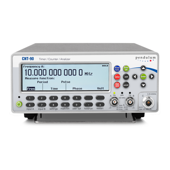
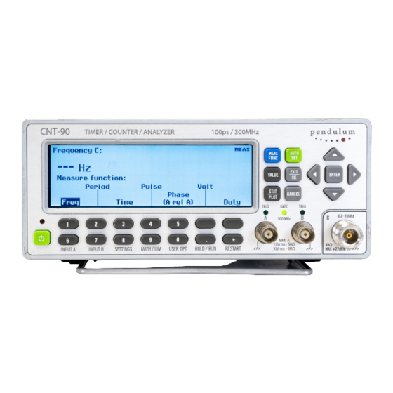
Timer/Counter/Analyzer
CNT-90, CNT-91, CNT-90/AN
Frequency Calibrator/Analyzer
CNT-91R
Microwave Counter/Analyzer
CNT-90XL
G E T T I N G S T A R T E D
M A N U A L
Part No.:
4031-600-90401
Revision:
1
Date:
6 March, 2020
Reproduction and distribution of this technical manual
is authorized for United States Government purposes.
© 2021 Pendulum Instruments.
All rights reserved.
Related Manuals for Pendulum CNT-90
Summary of Contents for Pendulum CNT-90
1. GENERAL INFORMATION User Manual CNT-90/91/91R/91RAF/90XL
About this Manual
This manual contains directions for use that apply to the Timer/Counter/Analyzers CNT-90 and CNT-91 as well as the Frequency Calibrator/Analyzer CNT-91R and CNT-91R/AF and the Microwave Counter/Analyzer CNT-90XL.
In order to simplify the references, these instruments are further referred to throughout this manual as the ‘9X’, whenever the information applies to all types. Differences are clearly marked.
Examples:
- CNT-90 means CNT-90 and CNT-90/XL
- CNT-90/91 means CNT-90 and CNT-91
- CNT-91(R) means CNT-91, CNT-91R and CNT-91R/AF
Chapter 8, Specifications is divided into four separate sections to increase legibility. Much of the contents is common, so redundant data is the price in this case.
Warranty
The Warranty Statement is part of the folder Important Information that is included with the shipment.
Declaration of Conformity
The complete text with formal statements concerning product identification, manufacturer and standards used for type testing is available on request.
2. Chapter 1: Preparation for Use
2.1. Preface
2.1.1. Introduction
Congratulations on your choice of instrument. It will serve you well and stay ahead of most competition for many years to come, whether in bench-top or rack system use. It gives significantly increased performance compared to traditional Timer/Counters. The ‘9X’ offers the following advantages:
- 12 digits of frequency resolution per second and 50 or 100 ps resolution, as a result of high-resolution interpolating reciprocal counting.
- A high measurement rate of up to 250k readings/s to internal memory.
- Optional oven-controlled timebase oscillators, except the CNT-91R & CNT-91R/AF, which have an ultra-stable rubidium oscillator.
- CNT-90, CNT-91(R): A variety of RF prescaler options with upper frequency limits ranging from 3 GHz to 20 GHz.
- CNT-91R/AF: Special version of CNT-91R with selected Rubidium oscillator, plus 5 Reference frequency outputs covering 100 kHz, 1 MHz, 5 MHz, and 10 MHz. Model CNT-91R/AF has a 3 GHz input C and CNT-91R/AF/20G has a 20 GHz input C as standard
- CNT-90XL: A number of microwave inputs with upper frequency limits ranging from 27 to 60 GHz.
- CNT-90(XL): Optional Pulsed RF for RF pulse characterization up to 60 GHz carrier frequency and down to 30 ns pulse width.
- Optional built-in Li-Ion battery supply realizes instant high-precision measurements in the field and true UPS operation.
- Integrated high performance GPIB interface using SCPI commands.
- A fast USB interface that replaces the traditional but slower RS-232 serial interface
- Optional external GPIB-to Ethernet controller that allows connection to LAN .
2.1.1.1. Powerful and Versatile Functions
A unique performance feature in your new instrument is the comprehensive arming possibilities, which allow you to characterize virtually any type of complex signal concerning frequency and time.
For instance, you can insert a delay between the external arming condition and the actual arming of the counter. Read more about Arming in Chapter 5, “Measurement Control”.
In addition to the traditional measurement functions of a timer/counter, these instruments have a multitude of other functions such as phase, duty factor, rise/fall-time and peak voltage. The counter can perform all measurement functions on both main inputs (A & B). Most measurement functions can be armed, either via one of the main inputs or via a separate arming channel (E).
By using the built-in mathematics and statistics functions, the instrument can process the measurement results on your benchtop, without the need for a controller. Math functions include inversion, scaling and offset. Statistics functions include Max, Min and Mean as well as Standard and Allan Deviation on sample sizes up to 2*109.
2.1.1.2. No Mistakes
You will soon find that your instrument is more or less self-explanatory with an intuitive user interface. A menu tree with few levels makes the timer/counter easy to operate. The large backlit graphic LCD is the center of information and can show you several signal parameters at the same time as well as setting status and operator messages.
Statistics based on measurement samples can easily be presented as histograms or trend plots in addition to standard numerical measurement results like max, min, mean and standard deviation.
The AUTO function triggers automatically on any input waveform. A bus-learn mode simplifies GPIB programming. With bus-learn mode, manual counter settings can be transferred to the controller for later reprogramming. There is no need to learn code and syntax for each individual counter setting if you are an occasional GPIB bus user.
2.1.2. Design Innovations
2.1.2.1. State of the Art Technology Gives Durable Use
These counters are designed for quality and durability. The design is highly integrated. The digital counting circuitry consists of just one custom-developed FPGA and a 32-bit microcontroller. The high integration and low component count reduces power consumption and results in an MTBF of 30,000 hours. Modern surface-mount technology ensures high production quality. A rugged mechanical construction, including a metal cabinet that withstands mechanical shocks and protects against EMI, is also a valuable feature.
2.1.2.2. High Resolution
The use of reciprocal interpolating counting in this new counter results in excellent relative resolution: 12 digits/s for all frequencies.
The measurement is synchronized with the input cycles instead of the timebase. Simultaneously with the normal “digital” counting, the counter makes analog measurements of the time between the start/stop trigger events and the next following clock pulse. This is done in four identical circuits by charging an integrating capacitor with a constant current, starting at the trigger event. Charging is stopped at the leading edge of the first following clock pulse. The stored charge in the integrating capacitor represents the time difference between the start trigger event and the leading edge of the first following clock pulse. A similar charge integration is made for the stop trigger event.
When the “digital” part of the measurement is ready, the stored charges in the capacitors are measured by means of Analog/Digital Converters.
The counter’s microprocessor calculates the result after completing all measurements, i.e. the digital time measurement and the analog interpolation measurements.
The result is that the basic “digital resolution” of + 1 clock pulse (10 ns) is reduced to 100 ps for the CNT-90 and 50 ps for the CNT-91(R).
Since the measurement is synchronized with the input signal, the resolution for frequency measurements is very high and independent of frequency.
CNT-91/91R features gap-free back-to-back frequency measurements, ensuring no missing periods The counters have 14 display digits to ensure that the display itself does not restrict the resolution.
2.1.3. Remote Control
This instrument is programmable via two interfaces, GPIB and USB.
The GPIB interface offers full general functionality and compliance with the latest standards in use, the IEEE 488.2 1987 for HW and the SCPI 1999 for SW.
In addition to this ‘native’ mode of operation there is also a second mode that emulates the Agilent 53131/132 command set for easy exchange of instruments in operational ATE systems. The USB interface is mainly intended for the lab environment in conjunction with the optional TimeView™ analysis software. The communication protocol is a proprietary version of SCPI.
2.1.3.1. Fast GPIB Bus
These counters are not only extremely powerful and versatile bench-top instruments, they also feature extraordinary bus properties.
The bus transfer rate is up to 4000 triggered measurements/s in CNT-91(R). Array measurements to the internal memory can reach 250 k measurements/s.
This very high measurement rate makes new measurements possible. For example, you can perform jitter analysis on several tens of thousands of pulse width measurements and capture them in less than a second.
An extensive Programmer’s Handbook helps you understand SCPI and counter programming.
The counter is easy to use in GPIB environments. A built-in bus-learn mode enables you to make all counter settings manually and transfer them to the controller. The response can later be used to reprogram the counter to the same settings. This eliminates the need for the occasional user to learn all individual programming codes.
Complete (manually set) counter settings can also be stored in 20 internal memory locations and can easily be recalled on a later occasion. Ten of them can be user protected.
2.2. Safety
2.2.1. Introduction
Even though we know that you are eager to get going, we urge you to take a few minutes to read through this part of the introductory chapter carefully before plugging the line connector into the wall outlet.
This instrument has been designed and tested for Measurement Category I, Pollution Degree 2, in accordance with EN/IEC 61010-1:2001 and CAN/CSA-C22.2 No. 61010-1-04 (including approval). It has been supplied in a safe condition. Study this manual thoroughly to acquire adequate knowledge of the instrument, especially the section on Safety Precautions hereafter and the section on Installation on page 1-7.
2.2.2. Safety Precautions
All equipment that can be connected to line power is a potential danger to life. Handling restrictions imposed on such equipment should be observed.
To ensure the correct and safe operation of the instrument, it is essential that you follow generally accepted safety procedures in addition to the safety precautions specified in this manual.
These units are designed for indoor use only.
The instrument is designed to be used by trained personnel only. Removing the cover for repair, maintenance, and adjustment of the instrument must be done by qualified personnel who are aware of the hazards involved.
The warranty commitments are rendered void if unauthorized access to the interior of the instrument has taken place during the given warranty period.
2.2.2.1. Caution and Warning Statements
CAUTION: Shows where incorrect procedures can cause damage to, or destruction of equipment or other property.
WARNING: Shows a potential danger that requires correct procedures or practices to prevent personal injury.
2.2.2.2. Symbols
 Shows where the protective ground terminal is connected inside the instrument. Never remove or loosen this screw
 This symbol is used for identifying the functional ground of an I/O signal. It is always connected to the instrument chassis.
 Indicates that the operator should consult the manual.
One such symbol is printed on the instrument, below the A and B inputs. It points out that the damage level for the input voltage decreases from 350 Vp to 12Vrms when you switch the input impedance from 1 MΩ to 50 Ω.
2.2.2.3. If in Doubt about Safety
Whenever you suspect that it is unsafe to use the instrument, you must make it inoperative by doing the following:
- Disconnect the line cord
- Clearly mark the instrument to prevent its further operation

- Inform your Pendulum Instruments representative.
For example, the instrument is likely to be unsafe if it is visibly damaged.
2.2.2.4. Disposal of Hazardous Materials
CNT-90 & CNT-90XL only
If your instrument was ordered with a built-in battery supply (Option 23/90), it contains 12 Li-Ion cells arranged as a fixed battery pack with internal protection circuitry.
Even though this type of cell does not cause environmental damage in the same way as NiCd, for instance, you should dispose of a worn-out battery pack at an authorized recycling station or return it to Spectracom.
Individual cells cannot be replaced.
2.3. Unpacking
Check that the shipment is complete and that no damage has occurred during transportation. If the contents are incomplete or damaged, file a claim with the carrier immediately. Also notify your local Spectracom sales or service organization in case repair or replacement may be required.
2.3.1. Check List
The shipment should contain the following:
- Counter/Timer/Analyzer CNT-90/91 or Frequency Calibrator/Analyzer CNT-91R or CNT-91R/AF or Microwave Counter/Analyzer CNT-90XL
- Line cord
- Brochure with Important Information
- Certificate of Calibration
- Options you ordered should be installed. See Identification below.
- CD including the following documentation in PDF:
- Getting Started Manual
- User’s Manual
- Programmer’s Handbook
2.3.2. Identification
The type plate on the rear panel shows type number and serial number. See illustrations on page 2-5 and 2-6. Installed options are listed under the menu User Options – About, where you can also find information on firmware version and calibration date. See page 2-15. The CNT-91R/AF version is identified by a unique identification marking, or UID. This permanent tag contains a barcode and allows customers to track easily their inventory and property.
2.3.3. Installation
2.3.3.1. Supply Voltage
Setting
The Counter may be connected to any AC supply with a voltage rating of 90 to 265 Vrms, 45 to 440 Hz. The counter automatically adjusts itself to the input line voltage.
Fuse
The secondary supply voltages are electronically protected against overload or short circuit. The primary line voltage side is protected by a fuse located on the power supply unit. The fuse rating covers the full voltage range. Consequently, there is no need for the user to replace the fuse under any operating conditions, nor is it accessible from the outside.
CAUTION: If this fuse is blown, it is likely that the power supply is badly damaged. Do not replace the fuse. Send the counter to the local Service Center.
Removing the cover for repair, maintenance and adjustment must be done by qualified and trained personnel only, who are fully aware of the hazards involved.
The warranty commitments are rendered void if unauthorized access to the interior of the instrument has taken place during the given warranty period.
2.3.3.2. Battery Supply
CNT-90 & CNT-90XL only
It is possible to run the counter from an optional battery supply, Option 23/90. You must charge the battery before use or storage. The counter charges the battery automatically when connected to line power or an external DC source, whether the instrument is in standby or turned on. See the specifications for charging time in different modes of operation.
2.3.3.3. Grounding
Grounding faults in the line voltage supply will make any instrument connected to it dangerous. Before connecting any unit to the power line, you must make sure that the protective ground functions correctly. Only then can a unit be connected to the power line and only by using a three-wire line cord. No other method of grounding is permitted. Extension cords must always have a protective ground conductor.
CAUTION: If a unit is moved from a cold to a warm environment, condensation may cause a shock hazard. Ensure, therefore, that the grounding requirements are strictly met.
WARNING: Never interrupt the grounding cord. Any interruption of the protective ground connection inside or outside the instrument or disconnection of the protective ground terminal is likely to make the instrument dangerous.
2.3.3.4. Orientation and Cooling
The counter can be operated in any position desired. Make sure that the air flow through the ventilation slots at the top, and side panels is not obstructed. Leave 5 centimeters (2 inches) of space around the counter.
2.3.3.5. Fold-Down Support
For bench-top use, a fold-down support is available for use underneath the counter. This support can also be used as a handle to carry the instrument.

2.3.3.6. Rackmount Adapter

If you have ordered a 19-inch rack-mount kit for your instrument, it has to be assembled after delivery of the instrument. The rackmount kit consists of the following:
- 2 brackets, (short, left; long, right)
- 4 screws, M5 x 8
- 4 screws, M6 x 8
WARNING: Do not perform any internal service or adjustment of this instrument unless you are qualified to do so. Before you remove the cover, disconnect mains cord and wait for one minute. Capacitors inside the instrument can hold their charge even if the instrument has been separated from all voltage sources.

2.3.3.7. Assembling the Rackmount Kit (Option 22/05)
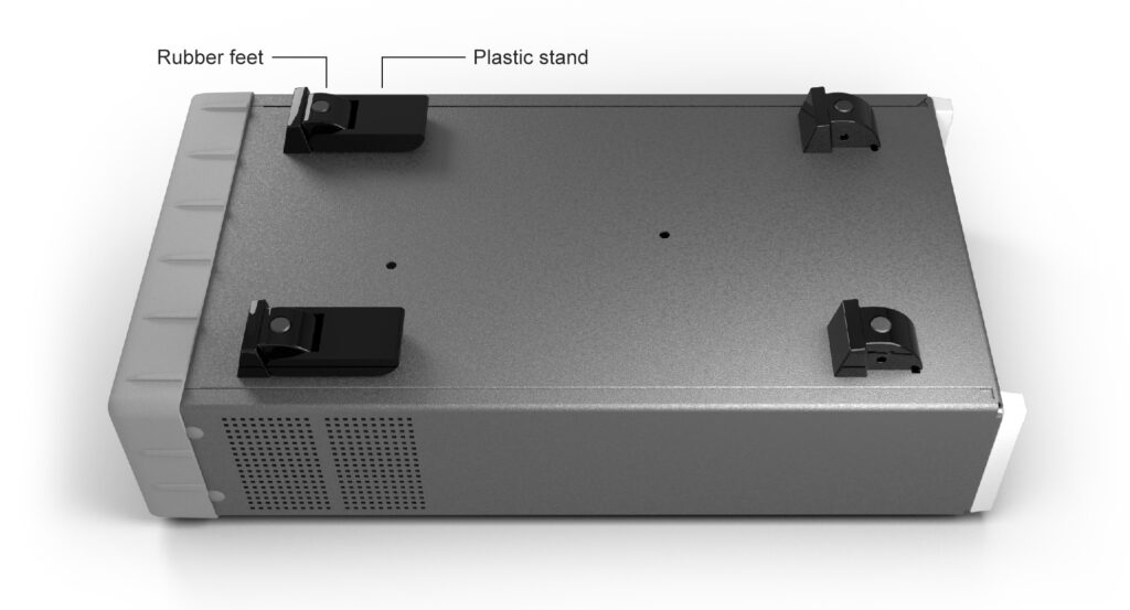
- Turn the devices upside down
- Remove the rubber feet in the plastic stand
- Loosen the screws underneath the rubber feet
- Remove the plastic stands
- Remove the four decorative plugs that cover the screw holes on the right and left side of the front panel.
Use the following steps to complete the side by side rack mount installation for your products. If necessary, refer to the item numbers in the following diagram for additional detail.
- Determine where you would like each unit positioned (i.e., on the right or left side)
- If plugs exist on the mounting holes on the front left and right side of product cover, remove and discard them
- Using screwdriver, screw the rack ear (Item #2) into place using the supplied 10mm screws (Item #5)
- Pinch the hinge pins together to separate the right and left hinge halves (Items #3 and 4)
- Attach hinge halves to the unit with hinge facing towards the front (as displayed in diagram)
- Using a screwdriver, remove the existing rear brackets on the back of each unit
- Using existing machine screws removed in previous steps, attach the rear brackets supplied with the mounting kit (Item #1)
- Pinch the hinge pins together into the stored position. Align the hinge halves together between the two units, and swing together side by side. The hinge pins should snap into place securing the front of the two units together
- Take the supplied Hex Spacer (Item #7) and place between middle rear brackets, and secure using the supplied 8mm screws (Item #6)
- Assembly is now ready for installation into standard 19” rack

3. Chapter 2: Using the Controls
3.1. Basic Controls
A more elaborate description of the front and rear panels including the user interface with its menu system follows after this introductory survey, the purpose of which is to make you familiar with the layout of the instrument. See also the appendix.


3.2. Secondary Controls
3.2.1. Connectors & Indicators

3.2.2. Rear Panel

Pulse Output [CNT-91(R) only]: User definable to serve as output for built-in pulse generator, gate indicator or alarm.
Optional Main Input Connectors (not with Option 23/90): The front panel inputs can be moved to the rear panel by means of an optional cable kit. Note that the input capacitance will be higher.
Type Plate: Indicates instrument type and serial number.
Fan: A temp. sensor controls the speed of the fan. Normal bench-top use means low speed, whereas rack-mounting and/or options may result in higher speed.
Protective Ground Terminal: This is where the protective ground wire is connected inside the instrument. Never tamper with this screw!
Line Power Inlet: AC 90-265 Vrms, 45-440 Hz, no range switching needed.
Reference Output: 10 MHz derived from the internal or, if present, the external reference.
External Reference Input: Can be automatically selected if a signal is present and approved as timebase source, see Chapter 9.
External Arming Input: See page 5-7.
GPIB Connector: Address set via User Options Menu.
Ext. DC Connector: Part of Option 23/90 for CNT-90(XL). Range: 12-18 V Note the polarity.
USB Connector: Universal Serial Bus (USB) for data communication with PC.
3.2.3. Rear Panel (CNT-91R/AF)

Pulse Output [CNT-91(R) only]: User definable to serve as output for built-in pulse generator, gate indicator or alarm.
Additional output frequencies Connectors: These connectors provide additional output frequencies which are, from left to right, 100kHz, 1MHz, 5MHz and 10MHz.
Type Plate: Indicates instrument type and serial number.
Fan: A temp. sensor controls the speed of the fan. Normal bench-top use means low speed, whereas rack-mounting and/or options may result in higher speed.
Protective Ground Terminal: This is where the protective ground wire is connected inside the instrument. Never tamper with this screw!
Line Power Inlet: AC 90-265 Vrms, 45-440 Hz, no range switching needed.
Reference Output: 10 MHz derived from the internal or, if present, the external reference.
External Reference Input: Can be automatically selected if a signal is present and approved as timebase source, see Chapter 9.
External Arming Input: See page 5-7.
GPIB Connector: Address set via User Options Menu.
USB Connector: Universal Serial Bus (USB) for data communication with PC.
3.3. Description of Keys
3.3.1. Power
The ON/OFF key is a toggling secondary power switch. Part of the instrument is always ON as long as power is applied, and this standby condition is indicated by a red LED above the key. This indicator is consequently not lit while the instrument is in operation.
CNT-91R and CNT-91R/AF only
While the rubidium oscillator is warming up, an open padlock symbol labeled RB is flashing at the top right corner of the display, indicating that the control loop is not locked. Normal time to lock is about 5 min. Do not start measuring until the unlock symbol disappears.
New Message Box
Information exchange between the rubidium oscillator and the CPU takes place over a serial bus. Any malfunction in the UART-con-trolled communication link will be reported in a pop-up message box on the display.
CNT-90(XL) w. Option 23/90
The User Interface Screens have two indicators near the upper right corner of the display. One is a power supply status indicator, and the other is a battery charging level indicator.
The status indicator shows:
- a fixed battery symbol when the internal battery is the active power source
- a charging battery symbol when the internal battery is being charged
- a power plug symbol when the mains is the active power source
- a power plug symbol on top of a battery symbol when the instrument has been prepared for UPS operation and charging is not going on
The charging level indicator shows:
- the relative charging level in percent
3.3.2. Select Function
This hard key is marked MEAS FUNC.
When you depress it, one of the menus below will open.
The current selection is indicated by text inversion that is also indicating the cursor position. Select the measurement function you want by depressing the corresponding softkey right below the display.
Alternatively, you can move the cursor to the wanted position with the RIGHT/LEFT arrow keys. Confirm by pressing ENTER.
A new menu will appear where the contents depend on the function. If you for instance have selected Frequency, you can then select between Frequency, Frequency Ratio and Frequency Burst. Finally you have to decide which input channel(s) to use.
3.3.3. Autoset/Preset
By depressing this key once after selecting the wanted measurement function and input channel, you will most probably get a measurement result. The AUTOSET system ensures that the trigger levels are set optimally for each combination of measurement function and input signal amplitude, provided relatively normal signal waveforms are applied. If Manual Trigger has been selected before pressing the AUTOSET key, the system will make the necessary adjustments once (Auto Once) and then return to its inactive condition.
AUTOSET performs the following functions:
- Set automatic trigger levels
- Switch attenuators to 1x
- Turn on the display
- Set Auto Trig Low Freq to
- 100 Hz, if fin >100 Hz, or to
- fin, if 10<fin<100 Hz, or to
- 10 Hz, if fin <10 Hz
A higher value means faster settling time.
By depressing this key twice within two seconds, you will enter the Preset mode, and a more extensive automatic setting will take place. In addition to the functions above, the following functions will be performed:
- Set Meas Time to 200 ms
- Switch off Hold-Off
- Set HOLD/RUN to RUN
- Switch off MATH/LIM
- Switch off Analog and Digital Filters
- Set Timebase Ref to Auto
- Switch off Arming
Default Settings
An even more comprehensive preset function can be performed by recalling the factory default settings. See page 2-16.
3.3.4. Move Cursor
There are four arrow keys for moving the cursor, normally marked by text inversion, around the menu trees in two dimensions.
3.3.5. Display Contrast
When no cursor is visible (no active menu selected), the UP/DOWN arrows are used for adjusting the LCD display contrast ratio.
3.3.6. Enter
The key marked ENTER enables you to confirm a choice without leaving your menu position.
3.3.7. Save & Exit
This hard key is marked EXIT/OK. You will confirm your selection by depressing it, and at the same time you will leave the current menu level for the next higher level.
3.3.8. Don’t Save & Exit
This hard key is marked CANCEL. By depressing it you will enter the preceding menu level without confirming any selections made at the current level. If the instrument is in REMOTE mode, this key is used for returning to LOCAL mode, unless LOCAL LOCKOUT has been programmed.
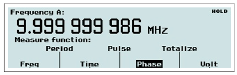
3.3.9. Presentation Modes
VALUE
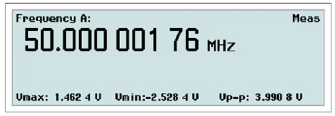
Value mode gives single line numerical presentation of individual results, where the main parameter is displayed in large characters with full resolution together with a number of auxiliary parameters in small characters with limited resolution.
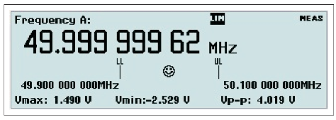
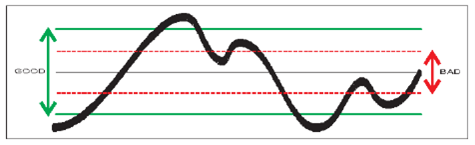
If Limit Behavior is set to Alarm and Limit Mode is set to Range you can visualize the deviation of your measurements in relation to the set limits. The numerical readout is now combined with a traditional analog pointer-type instrument, where the current value is represented by a “smiley”. The limits are presented as numerical values below the main parameter, and their positions are marked with vertical bars labelled LL (lower limit) and UL (upper limit) on the autoscaled graph.
If one of the limits has been exceeded, the limit indicator at the top of the display will be flashing. In case the current measurement is out of the visible graph area, it is indicated by means of a left or a right arrowhead.
STAT/PLOT
If you want to treat a number of measurements with statistical methods, this is the key to operate. There are three display modes available by toggling the key:
- Numerical
- Histogram
- Trend Plot
Numerical
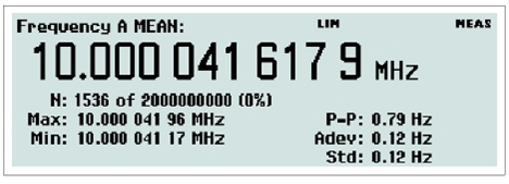
In this mode the statistical information is displayed as numerical data containing the following elements:
- Mean: mean value
- Max: maximum value
- Min: minimum value
- P-P: peak-to-peak deviation
- Adev: Allan deviation
- Std: Standard deviation
Histogram
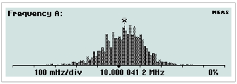
The bins in the histogram are always autoscaled based on the measured data. Limits, if enabled, and center of graph are shown as vertical dotted lines. Data outside the limits are not used for autoscaling but are replaced by an arrow indicating the direction where non-displayed values have been recorded.
Trend Plot
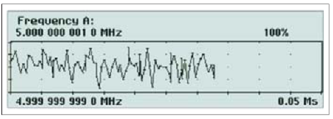
This mode is used for observing periodic fluctuations or possible trends. Each plot terminates (if HOLD is activated) or restarts (if RUN is activated) after the set number of samples. The trend plot is always autoscaled based on the measured data, starting with 0 at restart. Limits are shown as horizontal lines if enabled.
Remote
When the instrument is controlled from the GPIB bus or the USB bus, the operating mode changes to Remote, indicated by the label REM on the display. All front panel keys except CANCEL are then disabled. See also page 2-8 for more information on this key.
3.3.10. Entering Numeric Values
Sometimes you may want to enter constants and limits in a value input menu, for instance one of those that you can reach when you press the MATH/LIMIT key.
You may also want to select a value that is not in the list of fixed values available by pressing the UP/DOWN arrow keys. One example is Meas Time under SETTINGS.
A similar situation arises when the desired value is too far away to reach conveniently by incrementing or decrementing the original value with the UP/DOWN arrow keys. One example is the Trig Lvl setting as part of the INPUT A (B) settings.
Whenever it is possible to enter numeric values, the keys marked with 0-9;. (decimal point) and ± (stands for Change Sign)take on their alternative numeric meaning.
It is often convenient to enter values using the scientific format. For that purpose, the rightmost softkey is marked EE (stands for Enter Exponent), making it easy to switch between the mantissa and the exponent. Press EXIT/OK to store the new value or CANCEL to keep the old one.
3.3.11. Hard Menu Keys
These keys are mainly used for opening fixed menus from which further selections can be made by means of the softkeys or the cursor/select keys.
Input A (B)
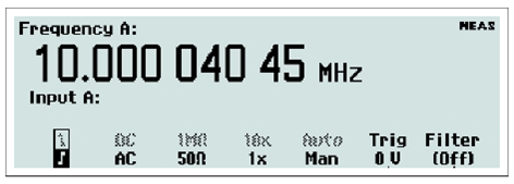
By depressing this key, the bottom part of the display will show the settings for Input A (B).
The active settings are in bold characters and can be changed by depressing the corresponding softkey below the display. You can also move the cursor, indicated by text inversion, to the desired position with the RIGHT/LEFT arrow keys and then change the active setting with the ENTER key.
The selections that can be made using this menu are:
- Trigger Slope: positive or negative, indicated by corresponding symbols
- Coupling: AC or DC
- Impedance: 50 W or 1 MW
- Attenuation: 1x or 10x
- Trigger:1 Manual or Auto
- Trigger Level:2 numerical input via front panel keyboard. If Auto Trigger is active, you can change the default trigger level manually as a percentage of the amplitude.
- Filter:3 On or Off
Notes: Always Auto when measuring risetime or falltime
The absolute level can either be adjusted using the up/down arrow keys or by pressing ENTER to reach the numerical input menu.
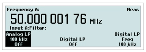
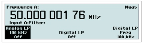
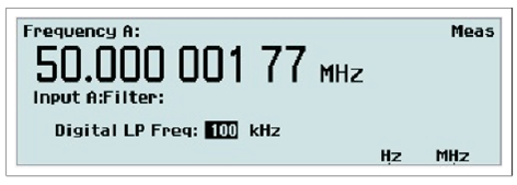
Pressing the corresponding softkey or ENTER opens the Filter Settings menu. See Fig. 2-10. You can select a fixed 100 kHz analog filter or an adjustable digital filter. The equivalent cutoff frequency is set via the value input menu that opens if you select Digital LP Frequency from the menu.
Input B
The settings under Input B are equal to those under Input A.
Settings
This key accesses a host of menus that affect the measurement. The figure above is valid after changing the default measuring time to 10 ms.
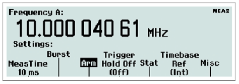
Meas Time
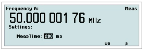
This value input menu is active if you select a frequency function. Longer measuring time means fewer measurements per second and gives higher resolution.
Burst
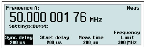
This settings menu is active if the selected measurement function is BURST – a special case of FREQUENCY – and facilitates measurements on pulse-modulated signals. Both the carrier frequency and the modulating frequency – the pulse repetition frequency (PRF) – can be measured, often without the support of an external arming signal.
Arm
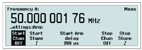
Arming is the general term used for the means to control the actual start/stop of a measurement. The normal free-running mode is inhibited and triggering takes place when certain pretrigger conditions are fulfilled.
The signal or signals used for initiating the arming can be applied to three channels (A, B, E), and the start channel can be different from the stop channel. All conditions can be set via this menu.
NOTE: Stop Delay can only be used for realizing the function Timed Totalize in the CNT-91(R).
Trigger Hold-Off
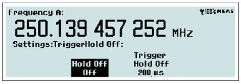
A value input menu is opened where you can set the delay during which the stop trigger conditions are ignored after the measurement
start. A typical use is to clean up signals generated by bouncing relay contacts.
Statistics
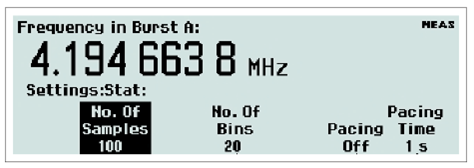
In this menu you can do the following:
- Set the number of samples used for calculation of various statistical measures.
- Set the number of bins in the histogram view.
- Pacing
The delay between measurements, called pacing, can be set to ON or OFF, and the time can be set within the range 2 ms – 500 s.
Timebase Reference
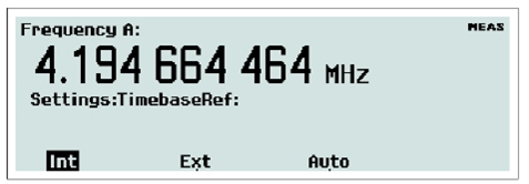
Here you can decide if the counter is to use an Internal or an External timebase. A third alternative is Auto. Then the external timebase will be selected if a valid signal is present at the reference input. The EXT REF indicator at the upper right corner of the display shows that the instrument is using an external timebase reference.
Miscellaneous
The options in this menu are:
- Smart Measure with submenus:
- Smart Time Interval (valid only if the selected measurement function is Time Interval) The counter decides by means of timestamping which measurement channel precedes the other.
- Smart Frequency (valid only If the selected measurement function is Frequency or Period Average) By means of continuous timestamping and regression analysis, the resolution is increased for measuring times between 0.2 s and 100 s.
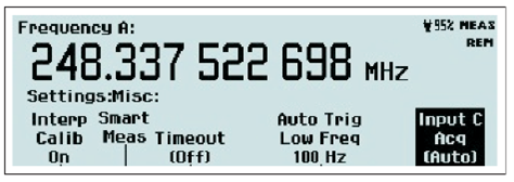
- Input C Acquisition (CNT-90XL only) Auto means that the whole specified frequency range is scanned for valid input signals.
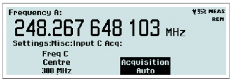
Manual means that a narrow band around the manually entered center frequency is monitored for valid input signals. This mode is compulsory when measuring burst signals but is also recommended for FM signals, when the approximate frequency is known. An additional feature is that the measurement results are presented much faster, as the acquisition process is skipped.
NOTE: Signal frequencies outside the manual capture range may cause erroneous results. In order to draw the operator’s attention to this eventuality, the sign “M.ACQ” is visible in the upper right corner of the display.
- Auto Trig Low Freq: In a value input menu you can set the lower frequency limit for automatic triggering and voltage measurements within the range 1 Hz – 100 kHz. A higher limit means faster settling time and consequently faster measurements.
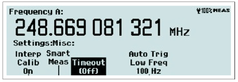
- Timeout: From this submenu you can activate/deactivate the timeout function and set the maximum time the instrument will wait for a pending measurement to finish before outputting a zero result. The range is 10 ms to 1000 s.
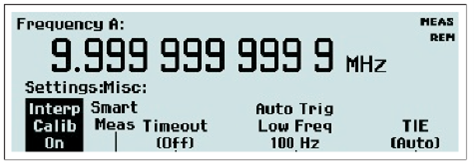
- Interpolatator Calibration: By switching off the interpolator calibration, you can increase the measurement speed at the expense of accuracy.
- TIE (CNT-91 only): From a submenu you can either let the counter choose the reference frequency automatically (Auto) or enter it manually.
Math/Limit
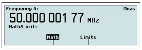
You enter a menu where you can choose between inputting data for the Mathematics or the Limits postprocessing unit.
The Math branch is used for modifying the measurement result mathematically before presentation on the display. Thus you can make the counter show directly what you want without tedious recalculations, e.g. revolutions/min instead of Hz.
The Limits branch is used for setting numerical limits and selecting the way the instrument will report the measurement results in relation to them.
Let us explore the Math submenu by pressing the corresponding softkey below the display.
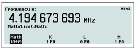
The display tells you that the Math function is not active, so press the Math Off key once to open the formula selection menu.
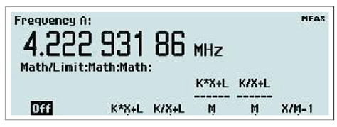
Select one of the five different formulas, where K, L and M are constants that the user can set to any value. X stands for the current non-modified measurement result.
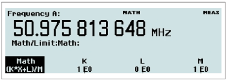
Each of the softkeys below the constant labels opens a value input menu like the one below.
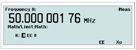
Use the numeric input keys to enter the mantissa and the exponent, and use the EE key to toggle between the input fields. The key marked X0 is used for entering the display reading as the value of the constant.
The Limit submenu is treated in a similar way, and its features are explored beginning on page 6-6.
User Options
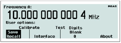
From this menu you can reach a number of submenus that do not directly affect the measurement. You can choose between a number of modes by pressing the corresponding softkey.
Save/Recall Menu
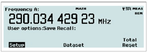
Twenty complete front panel setups can be stored in non-volatile memory. Access to the first ten memory positions is prohibited when Setup Protect is ON. Switching OFF Setup Protect releases all ten memory positions simultaneously.
The different setups can be individually labeled to make it easier for the operator to remember the application.
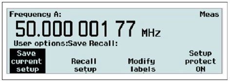
The following can be done:
- Save current setup
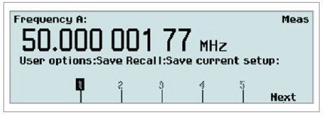
Browse through the available memory positions by using the RIGHT/LEFT arrow keys. For faster browsing, press the key Next to skip to the next memory bank. Press the softkey below the number (1-20) where you want to save the setting.
- Recall setup
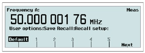
Select the memory position from which you want to retrieve the contents in the same way as under Save current setup above. You can also choose Default to restore the preprogrammed factory settings. See the table on page 2-19 for a complete list of these settings.
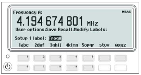
- Modify labels
Select a memory position to which you want to assign a label. See the descriptions under Save/Recall setup above. Now you can enter alphanumeric characters from the front panel. See the figure below.
The seven softkeys below the display are used for entering letters and digits in the same way as you write SMS messages on a cell phone.
- Setup protection
Toggle the softkey to switch between the ON/OFF modes. When ON is active, the memory positions 1-10 are all protected against accidental overwriting.
Dataset Menu
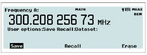
This feature is available in statistics mode only, and if HOLD has been pressed prior to initiating a measurement with RESTART. Up to 8 different datasets can be saved in FLASH memory, each containing up to 32000 samples. If the pending measurement has more than 32000 samples, only the last 32000 will be saved. A default label will be assigned to the dataset. It can be changed in a similar way as the setup labels. See Modify labels above.
- Save: Select a memory position, accept or change the name, and press OK.
- Recall: Select a memory position and press OK.
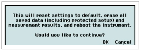
- Total Reset: The safety screen below will appear. Pressing OK will restore all factory settings and erase all user information.
Calibrate Menu
This menu entry is accessible only for calibration purposes and is password-protected.
Interface Menu
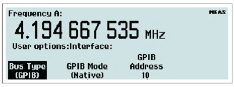
Select the active bus interface. The alternatives are GPIB and USB. If you select GPIB, you are also supposed to select the GPIB Mode and the GPIB Address. See the next two paragraphs.
GPIB Mode
There are two command systems to choose from.
- Native: The SCPI command set used in this mode fully exploits all the features of this instrument series.
- Compatible: The SCPI command set used in this mode is adapted to be compatible with Agilent 53131/132/181.
GPIB Address
Value input menu for setting the GPIB address.
Test
A general self-test is always performed every time you power-up the instrument, but you can order a specific test from this menu at any time.
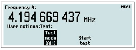
Press Test Mode to open the menu with available choices.

Select one of them and press Start Test to run it.
Digits Blank
Jittery measurement results can be made easier for an operator to read by masking one or more of the LSDs on the display.
Place the cursor at the submenu Digits Blank and increment/decrement the number by means of the UP/DOWN arrow keys, or press the soft key beneath the submenu and enter the desired number between 0 and 13 from the keyboard. The blanked digits will be represented by dashes on the display. The default value for the number of blanked digits is 0.
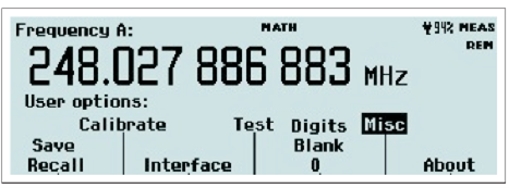
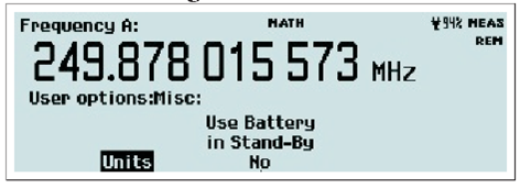
Misc (CNT-90XL & CNT-90 with Option 23/90)
The CNT-90XL without Option 23/90 has a single submenu called Units. By pressing this softkey you get to the submenu Power. Press Power and then select dBm or W as the unit of measurement, when either of the functions Frequency C or Power C is selected from the MEAS FUNC menu.
The CNT-90 with Option 23/90 has a single submenu called Use Battery in Standby. By toggling this softkey you can decide if the internal OCXO will remain powered or not when you turn off the instrument in battery operation mode.
The CNT-90XL with Option 23/90 has a combination of the two submenus mentioned above. See the figure below.
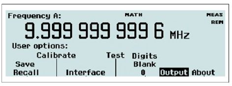
Output [CNT-91(R) only]
The rear panel pulse output can be used for three different purposes:
- pulse generator
- gate indicator
- alarm
Press the softkey Output to open the submenu below.
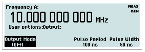
Off is the default mode and inhibits all activity on the output connector.
The pulse generator parameters Period and Width can be entered by first pressing the corresponding softkeys, then setting the numerical values as usual. By placing the cursor over the parameter, you can also set the values directly in 1-2-5 steps with the UP/DOWN arrow keys.
Press Output Mode to enter the mode selection menu below:
- Gate Open indicates to external equipment when a measurement is in progress.
- Pulse Generator activates a continuous pulse train having the parameters entered in the previous menu.
- Alarm can be set to be active low or active high. The MATH/LIM menu is used for setting up the behavior and the numerical limits that trigger the alarm.
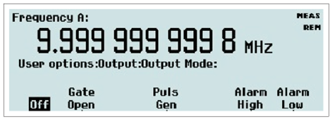
The amplitude is fixed at TTL levels into 50 Ω irrespective of the output mode.
About
- Here you can find information on:
- model
- serial number
- instrument firmware version
- timebase option & calibration date
- The CNT-91R reports “Rubidium” in this field.
- RF input option
- The CNT-90XL reports the upper frequency limit.
Hold/Run
This key serves the purpose of manual arming. A pending measurement will be finished and the result will remain on the display until a new measurement is triggered by pressing the RESTART key.
Restart
Often this key is operated in conjunction with the HOLD/RUN key (see above), but it can also be used in free-running mode, especially when long measuring times are being used, e.g. to initiate a new measurement after a change in the input signal. RESTART will not affect any front panel settings.
3.4. Default Settings
See page 2-16 to see how the following preprogrammed settings are recalled by a few keystrokes.
| PARAMETER | VALUE/SETTING |
| Input A & B | |
| Trigger Level | AUTO |
| Trigger Slope | POS |
| Impedance | 1 MW |
| Attenuator | 1x |
| Coupling | AC |
| Filter | OFF |
| Arming | |
| Start | OFF |
| Start Slope | POS |
| Start Arm Delay | 0 |
| Stop | OFF |
| Stop Slope | POS |
| Hold-Off | |
| Hold-Off State | OFF |
| Hold-Off Time | 200 ms |
| Time-Out | |
| Time-Out State | OFF |
| Time-Out Time | 100 ms |
| Statistics | |
| Statistics | OFF |
| No. of Samples | 100 |
| No. of Bins | 20 |
| Pacing State | OFF |
| Pacing Time | 20 ms |
| Mathematics | |
| Mathematics | OFF |
| Math Constants | K=1, L=0, M=1 |
| Limits | |
| Limit State | OFF |
| Limit Mode | RANGE |
| Lower Limit | 0 |
| Upper Limit | 0 |
| Burst | |
| Sync Delay | 400 ms |
| Start Delay | 0 |
| Meas. Time | 200 ms |
| Freq. Limit | 400 MHz |
| Miscellaneous | |
| Function | FREQA |
| Smart Frequency | AUTO |
| Smart Time Interval | OFF |
| Meas. Time | 200 ms |
| Auto Trig Low Freq | 100 Hz |
| Timebase Reference | AUTO |
| Blank Digits | 0 |
| Interpolator calibration | ON |
| Output (CNT-91(R)) | OFF |
4. Chapter 3: Input Signal Conditioning
4.1. Input Amplifier
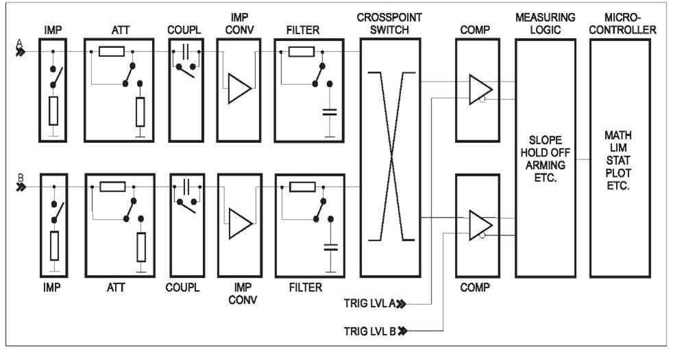
The input amplifiers are used for adapting the widely varying signals in the ambient world to the measuring logic of the timer/counter.
These amplifiers have many controls, and it is essential to understand how these controls work together and affect the signal.
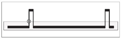
The block diagram below shows the order in which the different controls are connected. It is not a complete technical diagram but intended to help understanding the controls.
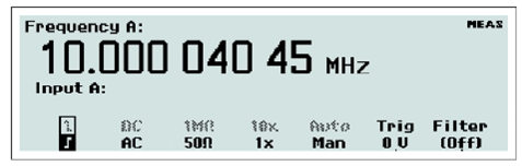
The menus from which you can adjust the settings for the two main measurement channels are reached by pressing INPUT A respectively INPUT B. See Figure 3-2. The active choices are shown in boldface on the bottom line.
4.1.1. Impedance
The input impedance can be set to 1 MΩ or 50 Ω by toggling the corresponding softkey.
CAUTION: Switching the impedance to 50 Ω when the input voltage is above 12 Vrms may cause permanent damage to the input circuitry.
4.1.2. Attenuation
The input signal’s amplitude can be attenuated by 1 or 10 by toggling the softkey marked 1x/10x. Use attenuation whenever the input signal exceeds the dynamic input voltage range ±5 V or else when attenuation can reduce the influence of noise and interference. See the section dealing with these matters at the end of this chapter.
4.1.3. Coupling
Switch between AC coupling and DC coupling by toggling the softkey AC/DC.
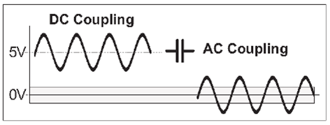
Use the AC coupling feature to eliminate unwanted DC signal components. Always use AC coupling when the AC signal is superimposed on a DC voltage that is higher than the trigger level setting range. However, we recommend AC coupling in many other measurement situations as well.
When you measure symmetrical signals, such as sine and square/triangle waves, AC coupling filters out all DC components. This means that a 0 V trigger level is always centered around the middle of the signal where triggering is most stable.
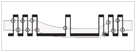
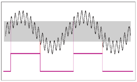
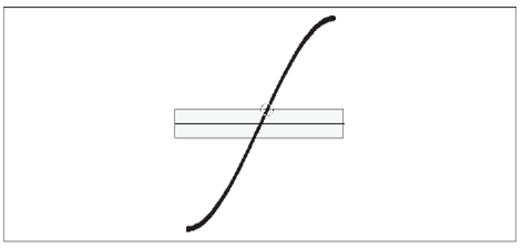
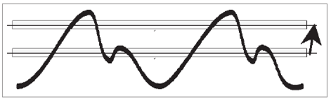
Signals with changing duty cycle or with a very low or high duty cycle do require DC coupling. Fig. 3-4 shows how pulses can be missed, while Fig. 3-5shows that triggering does not occur at all because the signal amplitude and the hysteresis band are not centered.
NOTE: For explanation of the hysteresis band, see page 4-3.
4.1.4. Filter
If you cannot obtain a stable reading, the signal-to-noise ratio (often designated S/N or SNR) might be too low, probably less than 6 to 10 dB. Then you should use a filter. Certain conditions call for special solutions like highpass, bandpass or notch filters, but usually the unwanted noise signals have higher frequency than the signal you are interested in. In that case you can utilize the built-in lowpass filters. There are both analog and digital filters, and they can also work together.
Analog Lowpass Filter
The counter has analog LP filters of RC type, one in each of the channels A and B, with a cutoff frequency of approximately 100 kHz, and a signal rejection of 20 dB at 1 MHz.
Accurate frequency measurements of noisy LF signals (up to 200 kHz) can be made when the noise components have significantly higher frequencies than the fundamental signal.
Digital Lowpass Filter
The digital LP filter utilizes the Hold-Off function described below.
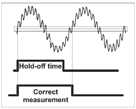
With trigger Hold-Off it is possible to insert a deadtime in the input trigger circuit. This means that the input of the counter ignores all hysteresis band crossings by the input signal during a preset time after the first trigger event.
When you set the Hold-Off time to approx. 75% of the cycle time of the signal, erroneous triggering is inhibited around the point where the input signal returns through the hysteresis band. When the signal reaches the trigger point of the next cycle, the set Hold-Off time has elapsed and a new and correct trigger will be initiated. Instead of letting you calculate a suitable Hold-Off time, the counter will do the job for you by converting the filter cutoff frequency you enter via the value input menu below to an equivalent Hold-Off time.
You should be aware of a few limitations to be able to use the digital filter feature effectively and unambiguously. First you must have a rough idea of the frequency to be measured. A cutoff frequency that is too low might give a perfectly stable reading that is too low. In such a case, triggering occurs only on every 2nd, 3rd or 4th cycle. A cutoff frequency that is too
high (>2 times the input frequency) also leads to a stable reading. Here one noise pulse is counted for each half-cycle.
Use an oscilloscope for verification if you are in doubt about the frequency and waveform of your input signal. The cutoff frequency setting range is very wide: 1 Hz – 50 MHz
4.1.5. Man/Auto
Toggle between manual and automatic triggering with this softkey. When Auto is active the counter automatically measures the peak-to-peak levels of the input signal and sets the trigger level to 50% of that value. The attenuation is also set automatically.
At rise/fall time measurements the trigger levels are automatically set to 10% and 90% of the peak values.
When Manual is active the trigger level is set in the value input menu designated Trig. See below. The current value can be read on the display before entering the menu.
Speed
The Auto-function measures amplitude and calculates trigger level rapidly, but if you aim at higher measurement speed without having to sacrifice the benefits of automatic triggering, then use the Auto Trig Low Freq function to set the lower frequency limit for voltage measurement.
If you know that the signal you are interested in always has a frequency higher than a certain value flow , then you can enter this value from a value input menu. The range for flow is 1 Hz to 100 kHz, and the default value is 100 Hz. The higher value, the faster measurement speed due to more rapid trigger level voltage detection.
Even faster measurement speed can be reached by setting the trigger levels manually. See Trig below.
Follow the instructions here to change the low-frequency limit:
- Press SETTINGS->Misc->Auto Trig Low Freq.
- Use the UP/DOWN arrow keys or the numeric input keys to change the low frequency limit to be used during the trigger level calculation, (default 100 Hz).
- Confirm your choice and leave the SETTINGS menu by pressing EXIT/OK three times.
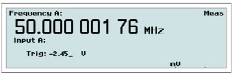
4.1.6. Trig
Value input menu for entering the trigger level manually.
Use the UP/DOWN arrow keys or the numeric input keys to set the trigger level. A blinking underscore indicates the cursor position where the next digit will appear. The LEFT arrow key is used for correction, i.e. deleting the position preceding the current cursor position.
NOTE: It is probably easier to make small adjustments around a fixed value by using the arrow keys for incrementation or decrementation. Keep the keys depressed for faster response
NOTE: Switching over from AUTO to MAN Trigger Level is automatic if you enter a trigger level manually.
Auto Once
Converting “Auto” to “Fixed”
The trigger levels used by the auto trigger can be frozen and turned into fixed trigger levels simply by toggling the MAN/AUTO key. The current calculated trigger level that is visible on the display under Trig will be the new fixed manual level. Subsequent measurements will be considerably faster since the signal levels are no longer monitored by the instrument. You should not use this method if the signal levels are unstable.
NOTE: You can use auto trigger on one input and fixed trigger levels on the other.
4.2. How to Reduce or Ignore Noise and Interference
Sensitive counter input circuits are of course also sensitive to noise. By matching the signal amplitude to the counter’s input sensitivity, you reduce the risk of erroneous counts from noise and interference. These could otherwise ruin a measurement.
To ensure reliable measuring results, the counter has the following functions to reduce or eliminate the effect of noise:
- 10x input attenuator
- Continuously variable trigger level
- Continuously variable hysteresis for some functions
- Analog low-pass noise suppression filter
- Digital low-pass filter (Trigger Hold-Off)
To make reliable measurements possible on very noisy signals, you may use several of the above features simultaneously. Optimizing the input amplitude and the trigger level, using the attenuator and the trigger control, is independent of input frequency and useful over the entire frequency range. LP filters, on the other hand, function selectively over a limited frequency range.
4.2.1. Trigger Hysteresis
The signal needs to cross the 20 mV input hysteresis band before triggering occurs. This hysteresis prevents the input from self-oscillating and reduces its sensitivity to noise. Other names for trigger hysteresis are “trigger sensitivity” and “noise immunity”. They explain the various characteristics of the hysteresis.
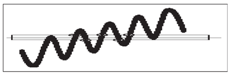
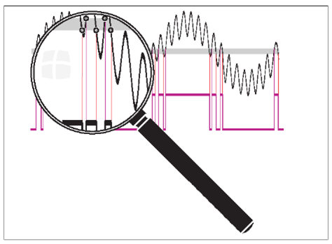
Fig. 3-10 and Fig. 3-12 show how spurious signals can cause the input signal to cross the trigger or hysteresis window more than once per input cycle and give erroneous counts.
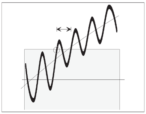
Fig. 3-13 shows that less noise still affects the trigger point by advancing or delaying it, but it does not cause erroneous counts. This trigger uncertainty is of particular importance when measuring low frequency signals, since the signal slew rate (in V/s) is low for LF signals. To reduce the trigger uncertainty, it is desirable to cross the hysteresis band as fast as possible.
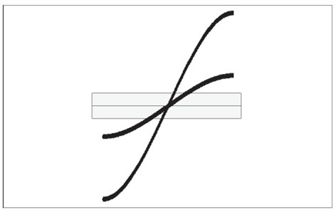
Fig. 3-14 shows that a high amplitude signal passes the hysteresis faster than a low amplitude signal. For low frequency measurements where the trigger uncertainty is of importance, do not attenuate the signal too much, and set the sensitivity of the counter high.
In practice however, trigger errors caused by erroneous counts (Fig. 3-10 and Fig. 3-12) are much more important and require just the opposite measures to be taken.
To avoid erroneous counting caused by spurious signals, you need to avoid excessive input signal amplitudes. This is particularly valid when measuring on high impedance circuitry and when using 1 MW input impedance. Under these conditions, the cables easily pick up noise.
External attenuation and the internal 10x attenuator reduce the signal amplitude, including the noise, while the internal sensitivity control in the counter reduces the counter’s sensitivity, including sensitivity to noise. Reduce excessive signal amplitudes with the 10x attenuator, or with an external coaxial attenuator, or a 10:1 probe.
4.2.2. How to use Trigger Level Setting
For most frequency measurements, the optimal triggering is obtained by positioning the mean trigger level at mid amplitude, using either a narrow or a wide hysteresis band, depending on the signal characteristics.
When measuring LF sine wave signals with little noise, you may want to measure with a high sensitivity (narrow hysteresis band) to reduce the trigger uncertainty. Triggering at or close to the middle of the signal leads to the smallest trigger (timing) error since the signal slope is steepest at the sine wave center, see Fig. 3-15.
When you have to avoid erroneous counts due to noisy signals, see Fig. 3-12, expanding the hysteresis window gives the best result if you still center the window around the middle of the input signal. The input signal excursions beyond the hysteresis band should be equally large.
Auto Trigger
For normal frequency measurements, i.e. without arming, the Auto Trigger function changes to Auto (Wide) Hysteresis, thus widening the hysteresis window to lie between 70 % and. 30 % of the peak-to-peak amplitude. This is done with a successive approximation method, by which the signal’s MIN. and MAX. levels are identified, i.e., the levels where triggering just stops. After this MIN./MAX. probing, the counter sets the trigger levels to the calculated values. The default relative trigger levels are indicated by 70 % on Input A and 30 % on Input B. These values can be manually adjusted between 50 % and 100 % on Input A and between 0 % and 50 % on Input B. The signal, however, is only applied to one channel.
Before each frequency measurement the counter repeats this signal probing to identify new MIN/MAX values. A prerequisite to enable AUTO triggering is therefore that the input signal is repetitive, i.e., >100 Hz (default). Another condition is that the signal amplitude does not change significantly after the measurement has started.
NOTE: AUTO trigger limits the maximum measuring rate when an automatic test system makes many measurements per second. Here you can increase the measuring rate by switching off this probing if the signal amplitude is constant. One single command and the AUTO trigger function determines the trigger level once and enters it as a fixed trigger level.
Manual Trigger
Switching to Man Trig also means Narrow Hysteresis at the last Auto Level. Pressing AUTOSET once starts a single automatic trigger level calculation (Auto Once). This calculated value, 50 % of the peak-to-peak amplitude, will be the new fixed trigger level, from which you can make manual adjustments if need be.
Harmonic Distortion
As rule of thumb, stable readings are free from noise or interference.
However, stable readings are not necessarily correct; harmonic distortion can cause erroneous yet stable readings. Sine wave signals with much harmonic distortion, see Fig. 3-17, can be measured correctly by shifting the trigger point to a suitable level or by using continuously variable sensitivity, see Fig. 3-16. You can also use Trigger Hold-Off, in case the measurement result is not in line with your expectations.
5. Chapter 4: Measuring Functions
-
Contents
-
Table of Contents
-
Bookmarks
Quick Links
Timer/Counter/Analyzer
CNT-90, CNT-91
Frequency Calibrator/Analyzer
CNT-91R
Microwave Counter/Analyzer
CNT-90XL
User’s Manual
Related Manuals for Pendulum CNT-90
Summary of Contents for Pendulum CNT-90
-
Page 1
Timer/Counter/Analyzer CNT-90, CNT-91 Frequency Calibrator/Analyzer CNT-91R Microwave Counter/Analyzer CNT-90XL User’s Manual… -
Page 1
Timer/Counter/Analyzer CNT-90, CNT-91 Frequency Calibrator/Analyzer CNT-91R Microwave Counter/Analyzer CNT-90XL User’s Manual Distributed by: Sie haben Fragen oder wünschen eine Beratung? Angebotsanfrage unter 07121 / 51 50 50 oder über info@datatec.de… -
Page 1
Timer/Counter/Analyzer CNT-90, CNT-91 Frequency Calibrator/Analyzer CNT-91R Microwave Counter/Analyzer CNT-90XL User’s Manual… -
Page 2
4031 600 90001 2020- 22 Edition © 2020, Pendulum Instruments… -
Page 2
4031 600 90001 2020- 22 Edition © 2020, Pendulum Instruments… -
Page 2
4031 600 90001 2017 — 20th Edition © 2017, Pendulum Instruments… -
Page 3: Table Of Contents
Frequency Measurements ….4-3 Environmental Considerations….. 1-6 FREQ A, B……….4-3 Unpacking ……..1-7 FREQ C………… 4-4 Check List ……….1-7 CNT-90/91(R)……..4-4 Identification……….1-7 CNT-90XL ………. 4-4 Installation……….1-8 RATIO A/B, B/A, C/A, C/B ……4-4 Supply Voltage……..1-8 BURST A, B, C ………
-
Page 4
5 Measurement Control Single A, B Back-to-Back ….4-14 Frequency A, B Back-to-Back … 4-14 About This Chapter ……..5-2 Time Measurements …… 4-15 Measurement Time ……5-2 Gate Indicator ……..5-2 Introduction ……….4-15 Single Measurements ……5-2 Triggering………. 4-15 Hold/Run &… -
Page 4
5 Measurement Control Single A, B Back-to-Back ….4-14 Frequency A, B Back-to-Back … 4-14 About This Chapter ……..5-2 Time Measurements …… 4-15 Measurement Time ……5-2 Gate Indicator ……..5-2 Introduction ……….4-15 Single Measurements ……5-2 Triggering………. 4-15 Hold/Run &… -
Page 4
Arming Examples……..5-9 Single A, B Back-to-Back ….4-14 Frequency A, B Back-to-Back … 4-14 Introduction to Arming Examples ..5-9 #1 Measuring the First Burst Pulse ..5-9 Time Measurements …… 4-15 #2 Measuring the Second Burst Introduction ……….4-15 Pulse………. -
Page 5
Power sensitivity……. 7-20 Ordering Information ……. 8-14 Power accuracy…….. 7-20 Timebase Options……..8-15 Battery Supply ……..7-21 Explanations……..8-15 Option 23/90 for CNT-90 & CNT-90XL only ……….. 7-21 CNT-90XL ……..8-16 8 Specifications Introduction……….8-17 Measurement Functions ……8-17 CNT-90 ……….8-2 Frequency A, B, C …… -
Page 5
Option 23/90 for CNT-90 & CNT-90XL Timebase Options……..8-15 only ……….. 7-13 Explanations……..8-15 CNT-90XL ……..8-16 8 Specifications Introduction……….8-17 CNT-90 ……….8-2 Measurement Functions ……8-17 Introduction ……….8-3 Frequency A, B, C ……8-17 Measurement Functions……8-3 Frequency Burst A, B ……. 8-17 Frequency A, B, C……. -
Page 6
Input and Output Specifications ….8-19 Input and Output Specifications….8-35 Inputs A and B……..8-19 Inputs A and B ……..8-35 Input C……….8-20 Input C (Option 10)……8-35 Rear Panel Inputs & Outputs …. 8-20 Input C (Option 13)……8-36 Input C (Options 14 &… -
Page 6
Input and Output Specifications ….8-19 Input and Output Specifications….8-35 Inputs A and B……..8-19 Inputs A and B ……..8-35 Input C……….8-20 Input C (Option 10)……8-35 Rear Panel Inputs & Outputs …. 8-20 Input C (Option 13)……8-36 Input C (Options 14 &… -
Page 6
Explanations ……..8-25 Timebase Specifications CNT-91R ..8-45 Explanations……..8-45 CNT-91(R) ……..8-30 CNT-91R/71B……..8-46 Introduction ……….8-31 Measurement Functions……8-31 Introduction……….8-47 Frequency A, B, C……8-31 Measurement Functions ……8-47 Frequency Burst A, B, C….8-31 Frequency A, B, C ……8-47 Period A, B, C Average ….. -
Page 7
Input and Output Specifications ….8-51 Inputs A and B……..8-51 Input C……….8-51 Rear Panel Inputs & Outputs …. 8-52 Auxiliary Functions……..8-52 Trigger Hold-Off…….. 8-52 External Start/Stop Arming ….8-52 Statistics……….. 8-52 Mathematics ……..8-53 Other Functions …….. 8-53 Display ………. -
Page 7
Input and Output Specifications ….8-51 Inputs A and B……..8-51 Input C……….8-51 Rear Panel Inputs & Outputs …. 8-52 Auxiliary Functions……..8-52 Trigger Hold-Off…….. 8-52 External Start/Stop Arming ….8-52 Statistics……….. 8-52 Mathematics ……..8-53 Other Functions …….. 8-53 Display ………. -
Page 7
10 Service ……10-2 Sales and Service Office 11 Appendix New Look……….11-2… -
Page 8: General Information
GENERAL INFORMATION About this Manual This manual contains directions for use that apply to the Timer/Counter/Analyzers CNT-90 and CNT-91 as well as the Frequency Calibrator/Analyzer CNT-91R and CNT-91R/71B and the Mi- crowave Counter/Analyzer CNT-90XL. In order to simplify the references, these instruments are further referred to throughout this manual as the ‘9X’, whenever the information applies to all types.
-
Page 9: Preparation For Use
Chapter 1 Preparation for Use…
-
Page 9: Preparation For Use
Chapter 1 Preparation for Use…
-
Page 9: Preparation For Use
Chapter 1 Preparation for Use…
-
Page 10: Preface
CNT-91R/71B, which have a fixed ultra- instrument is the comprehensive arming stable rubidium oscillator. possibilities, which allow you to characterize —CNT-90, CNT-91(R): virtually any type of complex signal A variety of RF prescaler options with upper concerning frequency and time.
-
Page 11: No Mistakes
Preface Design Innovations In addition to the traditional measurement functions of a timer/counter, these instruments have a multitude of other State of the Art Technology functions such as phase, duty factor, rise/fall-time and peak voltage. The counter Gives Durable Use can perform all measurement functions on These counters are designed for quality and both main inputs (A &…
-
Page 12: Remote Control
+ 1 clock pulse (10 ns) is reduced to 100 ps bus properties. for the CNT-90 and 50 ps for the CNT-91(R). The bus transfer rate is up to 4000 Since the measurement is synchronized with triggered measurements/s in CNT-91(R).
-
Page 12: Remote Control
+ 1 clock pulse (10 ns) is reduced to 100 ps bus properties. for the CNT-90 and 50 ps for the CNT-91(R). The bus transfer rate is up to 4000 Since the measurement is synchronized with triggered measurements/s in CNT-91(R).
-
Page 12: Remote Control
+ 1 clock pulse (10 ns) is reduced to 100 ps bus properties. for the CNT-90 and 50 ps for the CNT-91(R). The bus transfer rate is up to 4000 Since the measurement is synchronized with triggered measurements/s in CNT-91(R).
-
Page 13: Safety
Unpacking Safety Introduction Safety Precautions Even though we know that you are eager to All equipment that can be connected to line get going, we urge you to take a few minutes power is a potential danger to life. Handling to read through this part of the introductory restrictions imposed on such equipment chapter carefully before plugging the line…
-
Page 14: Caution And Warning Statements
NiCd, for instance, you should dispose o f a worn-out battery pack at an authorized recy- cling station or return it to Pendulum. Note: Individual cells cannot be replaced. USER MANUAL ● CNT 9x Series ● Rev.22 February 2020…
-
Page 14: Caution And Warning Statements
NiCd, for instance, you should dispose o f a worn-out battery pack at an authorized recy- cling station or return it to Pendulum. Note: Individual cells cannot be replaced. USER MANUAL ● CNT 9x Series ● Rev.22 February 2020…
-
Page 14: Caution And Warning Statements
NiCd, for instance, you should dispose o f a worn-out battery pack at an authorized recy- cling station or return it to Pendulum. Note: Individual cells cannot be replaced. USER MANUAL ● CNT 9x Series ● Rev.20 December 2017…
-
Page 15: Environmental Considerations
Unpacking Environmental Considerations This section provides information about the environmental impact of the product. Product End-of-Life Handling Observe the following guidelines when recycling an instrument or component: Equipment recycling Production of this equipment required the extraction and use of natural resources. The equipment may contain substances that could be harmful to the environment or human health if impropely handled at the product’s end of life.
-
Page 16: Unpacking
• User’s Manual incomplete or damaged, file a claim with the carrier immediately. Also notify your local • Programmer’s Handbook Pendulum sales or service organization in • Service Manual (CNT-91R/71B case repair or replacement may be required. only) Check List…
-
Page 16: Unpacking
• User’s Manual incomplete or damaged, file a claim with the carrier immediately. Also notify your local • Programmer’s Handbook Pendulum sales or service organization in • Service Manual (CNT-91R/71B case repair or replacement may be required. only) Check List…
-
Page 16: Unpacking
• User’s Manual incomplete or damaged, file a claim with the carrier immediately. Also notify your local • Programmer’s Handbook Pendulum sales or service organization in • Service Manual (CNT-91R/71B case repair or replacement may be required. only) Check List…
-
Page 17: Installation
Battery Supply The counter can be operated in any position desired. Make sure that the air flow through ■ CNT-90 & CNT-90XL only the ventilation slots at the top, and side panels is not obstructed. Leave 5 centimeters (2 It is possible to run the counter from an op- inches) of space around the counter.
-
Page 18: Fold-Down Support
Unpacking Fold-Down Support Capacitors inside the instrument can hold their charge even if the instrument has For bench-top use, a fold-down support is been separated from all voltage sources. available for use underneath the counter. This support can also be used as a handle to carry the instrument.
-
Page 19
Unpacking Use a screwdriver as shown in the following ■ Assembling the Rackmount Kit illustration or a pair of pliers to remove the — Make sure the power cord is springs holding each foot, then push out the disconnected from the instrument. feet. -
Page 19
Unpacking Use a screwdriver as shown in the following ■ Assembling the Rackmount Kit illustration or a pair of pliers to remove the — Make sure the power cord is springs holding each foot, then push out the disconnected from the instrument. feet. -
Page 19
Unpacking Use a screwdriver as shown in the following ■ Assembling the Rackmount Kit illustration or a pair of pliers to remove the — Make sure the power cord is springs holding each foot, then push out the disconnected from the instrument. feet. -
Page 20: Using The Controls
Chapter 2 Using the Controls…
-
Page 20: Using The Controls
Chapter 2 Using the Controls…
-
Page 20: Using The Controls
Chapter 2 Using the Controls…
-
Page 21: Basic Controls
Using the Controls Basic Controls A more elaborate description of the front and survey, the purpose of which is to make you familiar with the layout of the instrument. rear panels including the user interface with its menu system follows after this See also the appendix.
-
Page 21: Basic Controls
Using the Controls Basic Controls A more elaborate description of the front and survey, the purpose of which is to make you familiar with the layout of the instrument. rear panels including the user interface with its menu system follows after this See also the appendix.
-
Page 21: Basic Controls
Using the Controls Basic Controls A more elaborate description of the front and survey, the purpose of which is to make you familiar with the layout of the instrument. rear panels including the user interface with its menu system follows after this See also the appendix.
-
Page 22
Using the Controls STAT/PLOT VALUE MEAS FUNC AUTO SET CURSOR Enters one of three Enters the normal Adjusts input trigger Menu tree for CONTROL statistics numerical voltages selecting mea- The cursor position, presentation presentation mode automatically to the surement function. marked by text modes. -
Page 23: Secondary Controls
OK. indicators and information boxes. RF/MICROWAVE INPUT MAIN INPUTS TRIGGER GATE INDI- CNT-90/91(R): A DICATORS CATOR The two identical DC number of optional RF coupled channels A& B prescalers are in- A pending mea-…
-
Page 23: Secondary Controls
OK. indicators and information boxes. RF/MICROWAVE INPUT MAIN INPUTS TRIGGER GATE INDI- CNT-90/91(R): A DICATORS CATOR The two identical DC number of optional RF coupled channels A& B prescalers are in- A pending mea-…
-
Page 23: Secondary Controls
OK. indicators and information boxes. RF/MICROWAVE INPUT MAIN INPUTS TRIGGER GATE INDI- CNT-90/91(R): A DICATORS CATOR The two identical DC number of optional RF coupled channels A& B prescalers are in- A pending mea-…
-
Page 24: Rear Panel
Ext. DC Connector External Reference Input GPIB Connector Part of Option 23/90 for Can be automatically selected Address set via User Options CNT-90(XL). if a signal is present and Menu. Range: 12-18 V Note the approved as timebase source, polarity.
-
Page 24: Rear Panel
Ext. DC Connector External Reference Input GPIB Connector Part of Option 23/90 for Can be automatically selected Address set via User Options CNT-90(XL). if a signal is present and Menu. Range: 12-18 V Note the approved as timebase source, polarity.
-
Page 24: Rear Panel
Ext. DC Connector External Reference Input GPIB Connector Part of Option 23/90 for Can be automatically selected Address set via User Options CNT-90(XL). if a signal is present and Menu. Range: 12-18 V Note the approved as timebase source, polarity.
-
Page 25: Rear Panel (Cnt-91R/71B)
Using the Controls Rear Panel Additional output frequencies Connectors (CNT-91R/71B) Protective Ground These connectors provide additional output Type Plate Terminal frequencies which are, from left to right, 100kHz, Indicates instrument This is where the protective 1MHz, 5MHz and 10MHz. type and serial number. ground wire is connected inside the instrument.
-
Page 26: Description Of Keys
CPU takes place over a serial bus. Any malfunction in the UART-con-trolled communication link will be reported in a pop-up message box on the display. ■ CNT-90(XL) w. Option 23/90 The User Interface Screens have two indica- Fig. 2-3 CNT-91(R): Select measurement tors near the upper right corner of the display.
-
Page 27: Autoset/Preset
Using the Controls have selected Frequency, you can then select Timebase Ref Auto • between Frequency, Frequency Ratio and • Switch off Frequency Burst. Finally you have to decide ■ Default Settings which input channel(s) to use. An even more comprehensive preset function Autoset/Preset can be performed by recalling the factory de- fault settings.
-
Page 28: Presentation Modes
Using the Controls Presentation Modes ■ STAT/PLOT If you want to treat a number of measurements ■ VALUE with statistical methods, this is the key to operate. There are three display modes available by toggling the key: • Numerical • Histogram •…
-
Page 28: Presentation Modes
Using the Controls Presentation Modes ■ STAT/PLOT If you want to treat a number of measurements ■ VALUE with statistical methods, this is the key to operate. There are three display modes available by toggling the key: • Numerical • Histogram •…
-
Page 28: Presentation Modes
Using the Controls Presentation Modes ■ STAT/PLOT If you want to treat a number of measurements ■ VALUE with statistical methods, this is the key to operate. There are three display modes available by toggling the key: • Numerical • Histogram •…
-
Page 29: Entering Numeric Values
Using the Controls example is the setting as part of the Trig Lvl arrow indicating the direction where settings. INPUT A (B) non-displayed values have been recorded. Whenever it is possible to enter numeric val- Trend Plot ues, the keys marked with 0-9;. (decimal point) and ±…
-
Page 30
Using the Controls • Trigger Slope: positive or negative, indicated by corresponding symbols Coupling: AC or DC • Impedance: 50 or 1 M • Attenuation: 1x or 10x • Fig. 2-11 The main settings menu. Trigger: Manual or Auto •… -
Page 30
Using the Controls • Trigger Slope: positive or negative, indicated by corresponding symbols Coupling: AC or DC • Impedance: 50 or 1 M • Attenuation: 1x or 10x • Fig. 2-11 The main settings menu. Trigger: Manual or Auto •… -
Page 30
Using the Controls • Trigger Slope: positive or negative, indicated by corresponding symbols Coupling: AC or DC • Impedance: 50 or 1 M • Attenuation: 1x or 10x • Fig. 2-11 The main settings menu. Trigger: Manual or Auto •… -
Page 31
Using the Controls start. A typical use is to clean up signals gen- erated by bouncing relay contacts. Fig. 2-14 CNT-90 & CNT-90XL: Setting arming conditions. CNT-91(R): Setting arming conditions. Fig. 2-15 Arming is the general term used for the means to control the actual start/stop of a measurement. -
Page 32
Using the Controls Statistics Fig. 2-17 Entering statistics parameters. In this menu you can do the following: • Set the number of samples used for calculation of various statistical measures. • Set the number of bins in the histogram view. •… -
Page 32
Using the Controls Statistics Fig. 2-17 Entering statistics parameters. In this menu you can do the following: • Set the number of samples used for calculation of various statistical measures. • Set the number of bins in the histogram view. •… -
Page 32
Using the Controls Statistics Fig. 2-17 Entering statistics parameters. In this menu you can do the following: • Set the number of samples used for calculation of various statistical measures. • Set the number of bins in the histogram view. •… -
Page 33
Using the Controls Miscellaneous Fig. 2-22 CNT-90XL: The ‘Input C Acquisition’ Fig. 2-19 CNT-90: The ‘Misc’ submenu. submenu. Manual means that a narrow band around the manually entered center frequency is monitored for valid input signals. This mode is compulsory… -
Page 33
Using the Controls Miscellaneous Fig. 2-22 CNT-90XL: The ‘Input C Acquisition’ Fig. 2-19 CNT-90: The ‘Misc’ submenu. submenu. Manual means that a narrow band around the manually entered center frequency is monitored for valid input signals. This mode is compulsory… -
Page 33
Using the Controls Miscellaneous Fig. 2-22 CNT-90XL: The ‘Input C Acquisition’ Fig. 2-19 CNT-90: The ‘Misc’ submenu. submenu. Manual means that a narrow band around the manually entered center frequency is monitored for valid input signals. This mode is compulsory… -
Page 34
Using the Controls The display tells you that the Math function is ■ Math/Limit not active, so press the key once to Math Off open the formula selection menu. Select one of the five different formulas, where K, L and M are constants that the user can set to any value. -
Page 34
Using the Controls The display tells you that the Math function is ■ Math/Limit not active, so press the key once to Math Off open the formula selection menu. Select one of the five different formulas, where K, L and M are constants that the user can set to any value. -
Page 34
Using the Controls The display tells you that the Math function is ■ Math/Limit not active, so press the key once to Math Off open the formula selection menu. Select one of the five different formulas, where K, L and M are constants that the user can set to any value. -
Page 35
Fig. 2-28 CNT-90: The User Options menu. beled to make it easier for the operator to re- member the application. Fig. 2-29 CNT-90XL & CNT-90 with Option 23/90: Fig. 2-32 The memory management menu The User Options menu. after pressing Setup. -
Page 35
Fig. 2-28 CNT-90: The User Options menu. beled to make it easier for the operator to re- member the application. Fig. 2-29 CNT-90XL & CNT-90 with Option 23/90: Fig. 2-32 The memory management menu The User Options menu. after pressing Setup. -
Page 35
Fig. 2-28 CNT-90: The User Options menu. beled to make it easier for the operator to re- member the application. Fig. 2-29 CNT-90XL & CNT-90 with Option 23/90: Fig. 2-32 The memory management menu The User Options menu. after pressing Setup. -
Page 36
Using the Controls Dataset Menu • Recall setup Fig. 2-34 Selecting memory position for recalling The memory management menu after Fig. 2-36 a measurement setup. pressing Dataset. This feature is available in statistics mode Select the memory position from which you want to retrieve the contents in the same way only, and if has been pressed prior to… -
Page 37
Frequency C or Power C is selected from the menu. MEAS FUNC The CNT-90 with Option 23/90 has a single Self-test menu. Fig. 2-39 submenu called Use Battery in Standby. By toggling this softkey you can decide if the in-… -
Page 37
Frequency C or Power C is selected from the menu. MEAS FUNC The CNT-90 with Option 23/90 has a single Self-test menu. Fig. 2-39 submenu called Use Battery in Standby. By toggling this softkey you can decide if the in-… -
Page 37
Frequency C or Power C is selected from the menu. MEAS FUNC The CNT-90 with Option 23/90 has a single Self-test menu. Fig. 2-39 submenu called Use Battery in Standby. By toggling this softkey you can decide if the in-… -
Page 38
Using the Controls The CNT-90XL with Option 23/90 has a • Pulse Generator activates a continuous pulse combination of the two submenus mentioned train having the parameters entered in the previous menu. above. See the figure below. • Alarm can be set to be active low or active high. -
Page 38
Using the Controls The CNT-90XL with Option 23/90 has a • Pulse Generator activates a continuous pulse combination of the two submenus mentioned train having the parameters entered in the previous menu. above. See the figure below. • Alarm can be set to be active low or active high. -
Page 38
Using the Controls The CNT-90XL with Option 23/90 has a • Pulse Generator activates a continuous pulse combination of the two submenus mentioned train having the parameters entered in the previous menu. above. See the figure below. • Alarm can be set to be active low or active high. -
Page 39: Default Settings
Using the Controls Default Settings See page 2-16 to see how the following prepro- grammed settings are recalled by a few key- strokes. PARAMETER VALUE/SETTING PARAMETER VALUE/SETTING Math Constants K=1, L=0, M=1 Input A & B Limits Trigger Level AUTO Limit State Trigger Slope Limit Mode…
-
Page 40
This page is intentionally left blank. -
Page 40
This page is intentionally left blank. -
Page 40
This page is intentionally left blank. -
Page 41: Input Signal Conditioning
Chapter 3 Input Signal Conditioning…
-
Page 41: Input Signal Conditioning
Chapter 3 Input Signal Conditioning…
-
Page 41: Input Signal Conditioning
Chapter 3 Input Signal Conditioning…
-
Page 42: Input Amplifier
Input Signaling Conditioning Input Amplifier The input amplifiers are used for adapting the widely varying signals in the ambient world to the measuring logic of the Input settings menu. Fig. 3-2 timer/counter. These amplifiers have many controls, and it Impedance is essential to understand how these The input impedance can be set to 1 M…
-
Page 43: Coupling
Input Signaling Conditioning else when attenuation can reduce the influence of does not occur at all because the signal ampli- noise and interference. See the section dealing tude and the hysteresis band are not centered. with these matters at the end of this chapter. NOTE: For explanation of the hysteresis band, see page 4-3.
-
Page 44: Man/Auto
Input Signaling Conditioning high (>2 times the input frequency) also leads ■ Digital Lowpass Filter to a stable reading. Here one noise pulse is counted for each half-cycle. The digital LP filter utilizes the Hold-Off function described below. Use an oscilloscope for verification if you are in doubt about the frequency and waveform of With trigger Hold-Off it is possible to insert a your input signal.
-
Page 45: Trig
Input Signaling Conditioning A blinking underscore indicates the cursor po- ■ Speed sition where the next digit will appear. The The Auto-function measures amplitude and arrow key is used for correction, i.e. LEFT calculates trigger level rapidly, but if you aim deleting the position preceding the current at higher measurement speed without having cursor position.
-
Page 46: How To Reduce Or Ignore Noise And Interference
Input Signaling Conditioning How to Reduce or To ensure reliable measuring results, the coun- ter has the following functions to reduce or Ignore Noise and eliminate the effect of noise: — 10x input attenuator Interference — Continuously variable trigger level — Continuously variable hysteresis for some Sensitive counter input circuits are of course functions…
-
Page 47: How To Use Trigger Level Setting
Input Signaling Conditioning In practice however, trigger errors caused by erroneous counts (Fig. 3-10 and Fig. 3-12) are much more important and require just the op- posite measures to be taken. To avoid erroneous counting caused by spuri- ous signals, you need to avoid excessive input signal amplitudes.
-
Page 48
Input Signaling Conditioning close to the middle of the signal leads to the and the AUTO trigger function determines the smallest trigger (timing) error since the signal trigger level once and enters it as a fixed trigger level. slope is steepest at the sine wave center, see Fig. -
Page 48
Input Signaling Conditioning close to the middle of the signal leads to the and the AUTO trigger function determines the smallest trigger (timing) error since the signal trigger level once and enters it as a fixed trigger level. slope is steepest at the sine wave center, see Fig. -
Page 48
Input Signaling Conditioning close to the middle of the signal leads to the and the AUTO trigger function determines the smallest trigger (timing) error since the signal trigger level once and enters it as a fixed trigger level. slope is steepest at the sine wave center, see Fig. -
Page 49: Measuring Functions
Chapter 4 Measuring Functions…
-
Page 49: Measuring Functions
Chapter 4 Measuring Functions…
-
Page 49: Measuring Functions
Chapter 4 Measuring Functions…
-
Page 50: Introduction To This Chapter
Measuring Functions Introduction to This Chapter Selecting Function This chapter describes the different measuring functions of the counter. They See also the front panel layout on page 2-3 to have been grouped as follows: find the keys mentioned in this section together Frequency measurements with short descriptions.
-
Page 51: Frequency Measurements
Measuring Functions Frequency Measurements FREQ A, B Some of the settings made above by recalling the Default Setup can also be made by activating the key. Pressing it once AUTOSET The counter measures frequency between 0 means: Hz and 400 MHz on Input A and Input B. The —…
-
Page 52: Freq C
Measuring Functions FREQ C BURST A, B, C A burst signal as in Fig. 4-2 has a carrier CNT-90/91(R) wave (CW) frequency and a modulation frequency, also called the pulse repetition With an optional prescaler the counter can frequency (PRF), that switches the CW signal measure up to 3, 8, 15 or 20 GHz on Input C.
-
Page 52: Freq C
Note that the resolution calculations are very different as compared to frequency measurements. See page 8-55 for details. CNT-90/91(R) BURST A, B, C With an optional prescaler the counter can measure up to 3, 8, 15 or 20 GHz on Input C.
-
Page 52: Freq C
Note that the resolution calculations are very different as compared to frequency measurements. See page 8-55 for details. CNT-90/91(R) BURST A, B, C With an optional prescaler the counter can measure up to 3, 8, 15 or 20 GHz on Input C.
-
Page 53: Burst Measurements Using Manual Presetting
Measuring Functions without further tweaking in most cases. Some- times switching from ual trig- AUTO gering in the menus is enough to INPUT A/B get stable readings. The continually calculated trigger levels will then be fixed. Set the sync delay so that it expires Fig.
-
Page 53: Burst Measurements Using Manual Presetting
Measuring Functions — Press Always try using AUTOSET first. Then the and enter a value longer Start Delay Auto Trigger and the Auto Sync functions in than the transient part of the burst pulse. combination will give satisfactory results — Select (160/400 MHz) if Frequency Limit without further tweaking in most cases.
-
Page 54: Frequency Modulated Signals
Measuring Functions Frequency ■ How Does the Sync Delay Work? The sync delay works as an internal start arm- Modulated Signals ing delay: it prevents the start of a new mea- surement until the set sync delay has expired. A frequency modulated signal is a carrier See Fig.
-
Page 55: Max
Measuring Functions You will usually get good results with 0.1 s measuring result that is too high or too low. measurement time per sample and more than 30 samples (n 3 0). You can try out the opti- mal combination of sample size and measure- ment time for specific cases.
-
Page 55: Max
Measuring Functions You will usually get good results with 0.1 s measuring result that is too high or too low. measurement time per sample and more than 30 samples (n 3 0). You can try out the opti- mal combination of sample size and measure- ment time for specific cases.
-
Page 55: Max
Measuring Functions You will usually get good results with 0.1 s measuring result that is too high or too low. measurement time per sample and more than 30 samples (n 3 0). You can try out the opti- mal combination of sample size and measure- ment time for specific cases.
-
Page 56: Errors Min F
Measuring Functions like the burst measurements described earlier Δf in this manual. — Press and set SETTINGS STAT No.of Carrier Wave Frequency to 1000 or more. samples — Press and select a low value. Meas Time The carrier wave (CW) is only continuously present in a narrow amplitude band in the Press and watch Δf…
-
Page 57: Modulating Frequency
Measuring Functions Theory of Modulating Frequency The easiest way to measure the modulating Measurement frequency is after demodulation, for instance by means of a so-called RF-detector probe Reciprocal Counting (also known as a demodulator probe, e.g. Pomona type 5815) used with AC-coupling of Simple frequency counters count the number the input channel.
-
Page 58: Sample-Hold
Measuring Functions measure the actual gate time (tg) and the When no triggering has occurred during the number of cycles (n) that occurred during this time-out, the counter will show NO SIGNAL. gate time. Measuring Speed Thereafter, the counter calculates the fre- quency according to Mr.
-
Page 59
Measuring Functions Function Prescaling CNT-90/91(R): Prescaling May ■ Factor Influence Measurement Time FREQ A/B (400 MHz) Prescalers do affect the minimum measure- BURST A/B (<160MHz) ment time, inasmuch as short bursts have to BURST A/B (>160MHz PERIOD A/B AVG (400 MHz) -
Page 59
Measuring Functions Function Prescaling CNT-90/91(R): Prescaling May ■ Factor Influence Measurement Time FREQ A/B (400 MHz) Prescalers do affect the minimum measure- BURST A/B (<160MHz) ment time, inasmuch as short bursts have to BURST A/B (>160MHz PERIOD A/B AVG (400 MHz) -
Page 59
Measuring Functions Function Prescaling CNT-90/91(R): Prescaling May ■ Factor Influence Measurement Time FREQ A/B (400 MHz) Prescalers do affect the minimum measure- BURST A/B (<160MHz) ment time, inasmuch as short bursts have to BURST A/B (>160MHz PERIOD A/B AVG (400 MHz) -
Page 60
Measuring Functions ■ CNT-90/91(R): RF Signals ■ CNT-90XL: Microwave Conversion As mentioned before, a prescaler in the Measuring frequencies up to 20 GHz is possi- C-in-put divides the input frequency before it is ble with the top-performance prescaler option counted by the normal digital counting logic. -
Page 61: Period
Measuring Functions — Preacquisition — Frequency modulation causes an unstable The purpose of this process is to find out ‘n’ value calculation. Action: increase the if there is a measurable signal present at measuring time. the input, and if so, fix the LO frequency Power measurement that gives rise to an IF signal above a cer- Another feature in this instrument is the abil-…
-
Page 62: Single A, B Back-To-Back
Measuring Functions Single A, B Back-to-Back Thus a series of consecutive frequency aver- age measurements without dead time can be made in order to fulfil the requirements for ■ CNT-91(R) only correct calculation of Allan variance or This function benefits from the basic deviation.
-
Page 63: Time Measurements
Measuring Functions Time Measurements Introduction Triggering The set trigger level and trigger slope define Measuring the time between a start and a stop the start and stop triggering. condition on two separate channels is the basis for all time interval measurements. In addition is on, the counter sets the trigger level Auto to the fundamental function…
-
Page 64: Time Interval
Measuring Functions CNT-91(R): Time that virtually moves the trigger points by half the hysteresis band. Interval Error (TIE) Time Interval This function can be found under the function menu and is only applicable to clock Time signals, not data signals. All time interval functions can be found under the function menu Time.
-
Page 65: Pulse Width A/B
Measuring Functions The counter measures the time from when the See the paragraph on Auto Trigger (page 4-19) signal passes 10 % of its amplitude to when it to find out how overshoot or ringing may 71B- fect your measurement. passes 90 % of its amplitude.
-
Page 65: Pulse Width A/B
Measuring Functions The counter measures the time from when the See the paragraph on Auto Trigger (page 4-19) signal passes 10 % of its amplitude to when it to find out how overshoot or ringing may 71B- fect your measurement. passes 90 % of its amplitude.
-
Page 65: Pulse Width A/B
Measuring Functions The counter measures the time from when the See the paragraph on Auto Trigger (page 4-19) signal passes 10 % of its amplitude to when it to find out how overshoot or ringing may 71B- fect your measurement. passes 90 % of its amplitude.
-
Page 66: Measurement Errors
Measuring Functions Overdrive and Pulse The total measurement time will be doubled compared to a single Rounding measurement, because «Duty» requires 2 measurement steps. Additional timing errors may be caused by triggering with insufficient overdrive, see Fig- ure 4-18. When triggering occurs too close to Measurement Errors the maximum voltage of a pulse, two phenom- ena may influence your measurement uncer-…
-
Page 67: Auto Trigger
Measuring Functions Auto Trigger Auto Trigger is a great help especially when you measure on unknown signals. However, overshoot and ringing may cause Auto choose slightly wrong MIN and MAX signal levels. This does not affect measurements like frequency, but transition time measurements may be affected.
-
Page 68: Phase
Measuring Functions Phase What is Phase? channel B are enough to calculate the result, including sign. Phase is the time difference between two sig- nals of the same frequency, expressed as an Resolution angle. Fig. 4-19 Phase delay. The traditional method to measure phase de- Fig.
-
Page 68: Phase
Measuring Functions Phase What is Phase? channel B are enough to calculate the result, including sign. Phase is the time difference between two sig- nals of the same frequency, expressed as an Resolution angle. Fig. 4-19 Phase delay. The traditional method to measure phase de- Fig.
-
Page 68: Phase
Measuring Functions Phase What is Phase? channel B are enough to calculate the result, including sign. Phase is the time difference between two sig- nals of the same frequency, expressed as an Resolution angle. Fig. 4-19 Phase delay. The traditional method to measure phase de- Fig.
-
Page 69: Inaccuracies
Measuring Functions The trigger noise error consists of start and Inaccuracies stop trigger errors that should be added. For sinusoidal input signals each error is: The inaccuracy of Phase A-B measurements depends on several external parameters: — Input signal frequency —…
-
Page 69: Inaccuracies
Measuring Functions The trigger noise error consists of start and Inaccuracies stop trigger errors that should be added. For sinusoidal input signals each error is: The inaccuracy of Phase A-B measurements depends on several external parameters: — Input signal frequency —…
-
Page 69: Inaccuracies
Measuring Functions The trigger noise error consists of start and Inaccuracies stop trigger errors that should be added. For sinusoidal input signals each error is: The inaccuracy of Phase A-B measurements depends on several external parameters: — Input signal frequency —…
-
Page 70
Measuring Functions and calculate the mean value from a number the recovery point -15 mV. This kind of tim- of samples. ing error is cancelled out by using hysteresis compensation. ■ Systematic Errors in Phase Hysteresis compensation means that the mi- Measurements crocomputer can offset the trigger level so Systematic errors consist o f 3 elements:… -
Page 71
Measuring Functions Vpeak (A) Vpeak (B) Worst case calibration has to be repeated if the systematic error frequency or the amplitude changes. 4°+4° 8° 150 mV 150 mV 1.5 V 150 mV 0.4°+4° = 4.4° Method 2: 1.5 V 1.5V 0.4°+0.4°=0.8°… -
Page 71
Measuring Functions Vpeak (A) Vpeak (B) Worst case calibration has to be repeated if the systematic error frequency or the amplitude changes. 4°+4° 8° 150 mV 150 mV 1.5 V 150 mV 0.4°+4° = 4.4° Method 2: 1.5 V 1.5V 0.4°+0.4°=0.8°… -
Page 71
Measuring Functions Vpeak (A) Vpeak (B) Worst case calibration has to be repeated if the systematic error frequency or the amplitude changes. 4°+4° 8° 150 mV 150 mV 1.5 V 150 mV 0.4°+4° = 4.4° Method 2: 1.5 V 1.5V 0.4°+0.4°=0.8°… -
Page 72: Totalize [Cnt-91(R) Only]
Measuring Functions Totalize [CNT-91(R) only] Totalize in General TOT A MAN This mode enables you to totalize (count) the functions add up the number of Totalize number of trigger events on Channel A. trigger events on the two counter inputs A Aux- iliary calculated parameters are and B.
-
Page 73: Applications
Measuring Functions TOT A-B MAN Unlike the manual functions, the Totalize armed variants resemble the other measure- ment functions inasmuch as they allow block This mode enables you to calculate the and pacing control. Consequently all the Sta- difference between trigger events on Channel tistics functions are available.
-
Page 74
Measuring Functions Stop Channel Stop Delay — — Select Decide if you need to insert a delay (10 ns — 2 s) during which the gate will not Stop Slope — respond to the control signal on the Select NEG (marked by a falling edge Stop Channel. -
Page 74
Measuring Functions Stop Channel Stop Delay — — Select Decide if you need to insert a delay (10 ns — 2 s) during which the gate will not Stop Slope — respond to the control signal on the Select NEG (marked by a falling edge Stop Channel. -
Page 74
Measuring Functions Stop Channel Stop Delay — — Select Decide if you need to insert a delay (10 ns — 2 s) during which the gate will not Stop Slope — respond to the control signal on the Select NEG (marked by a falling edge Stop Channel. -
Page 75: Voltage
Measuring Functions Voltage , Vmin, V Press . The counter can MEAS FUNC Volt measure the input voltage levels V and V on DC-input voltages and on repetitive signals between 1 Hz and 400 MHz. Fig. 4-21 The voltage is determined The default low frequency limit is 20 Hz but by making a series of trigger can be changed via the…
-
Page 76
Measuring Functions When the waveform (e.g. sinusoidal, triangu- lar, square) of the input signal is known, its crest factor, defined as the quotient (Q ) of the peak (V ) and RMS (V values, can be rms) used to set the constant K in the mathematical function K*X+L. -
Page 76
Measuring Functions When the waveform (e.g. sinusoidal, triangu- lar, square) of the input signal is known, its crest factor, defined as the quotient (Q ) of the peak (V ) and RMS (V values, can be rms) used to set the constant K in the mathematical function K*X+L. -
Page 76
Measuring Functions When the waveform (e.g. sinusoidal, triangu- lar, square) of the input signal is known, its crest factor, defined as the quotient (Q ) of the peak (V ) and RMS (V values, can be rms) used to set the constant K in the mathematical function K*X+L. -
Page 77: Pulsed Signals [Cnt-90Xl Option 28 Only]
Pulsed Signals [CNT-90 XL option 28 only] Start Delay: internal signals may need some time to be properly NTRODUCTION established. Start delay is useful to skip initial signal transient response to make sure that measurement starts when signal is stable.
-
Page 77: Pulsed Signals [Cnt-90Xl Option 28 Only]
Measuring Functions Pulsed Signals [CNT-90 XL option 28 only] Start Delay: internal signals may need some time to be properly NTRODUCTION established. Start delay is useful to skip initial signal transient response to make sure that measurement starts when signal is stable.
-
Page 78
SETTINGS Pulsed RF Start Delay ELECTING ULSED SETTINGS Pulsed RF Meas Time MEASUREMENTS SETTINGS Pulsed RF Sensitivity If Option 28 is installed in CNT-90XL, the Pulsed RF measurements are found by pressing the MEAS key and selecting Pulsed RF: The various Pulsed RF parameters are thereafter displayed: — Frequency in pulse — Repetition (PRI and PRF) -
Page 78
Measuring Functions Frequency in Pulse Note: For very short pulses (nanoseconds and lower microseconds), the resolution is limited in a single shot measurement (Values mode). To improve resolution, you should switch to STAT mode and do Statistical measurements and read the Mean Frequency value. For example 100 samples average will give one additional display digit and 10000 samples will give two additional digits. -
Page 79
ULSE IDTH Select Positive Pulse Width measurement via the MEAS →Pulsed RF →Width →Pos →C Set corresponding measurement settings in the following menus: — SETTINGS → Pulsed RF → Sensitivity SETTINGS →Pulsed RF →Sensitivity. SETTINGS →Misc →Input C Acq →Center frequency ULSE IDTH Select Negative Pulse Width measurement via the… -
Page 79
Measuring Functions (this function is also available via the SETTINGS Pulsed RF Start Delay SETTINGS Pulsed RF Meas Time menu). MEAS → Repetition → PRI →C SETTINGS Pulsed RF Sensitivity Set corresponding masureent settings in the following menus: SETTINGS →… -
Page 79
Measuring Functions (this function is also available via the SETTINGS Pulsed RF Start Delay SETTINGS Pulsed RF Meas Time menu). MEAS → Repetition → PRI →C SETTINGS Pulsed RF Sensitivity Set corresponding masureent settings in the following menus: SETTINGS →… -
Page 80
OWER CNT-90XL option 28 is also able to measure the power within pulses by selecting the function in the appropriate menu: MEAS → Pulsed RF → Power ON → C Set corresponding measurement settings in the following menus: SETTINGS Pulsed RF Start Delay. SETTINGS … -
Page 80
Measuring Functions ACTOR Select Negative duty factor measurement via the Select Pulse Repetition Frequency measurement via the MEAS → Pulsed RF → Width → Duty Factor Neg → C MEAS Pulsed RF Repetition PRF C. Set corresponding measurement settings in the following menus: Set corresponding measurement settings in the following menus: SETTINGS … -
Page 81
Chapter 5 Measurement Control… -
Page 81
Chapter 5 Measurement Control… -
Page 81
Chapter 5 Measurement Control… -
Page 82: About This Chapter
Measurement Control About This Chapter The exceptions are Frequency Period Average. This chapter explains how you can control is not relevant for V Single Average the start and stop of measurements and what or V measurements. you can obtain by doing so. The chapter starts by explaining the keys and the Hold/Run &…
-
Page 83: Start Arming
Measurement Control Arming is somewhat complicated yet gives the flexibility to perform a measurement on a specific portion of a complex signal, like a frequency measurement on the color burst contained in a composite video signal. Other examples of arming can be found later in this chapter, starting on page 5-9.
-
Page 84: Controlling Measurement Timing
Measurement Control Controlling Measurement Timing The Measurement Process — The set measurement time has expired (ap- plies to Frequency Period Average measurements only). Basic Free-running Measurements — The input signal fulfils the stop trigger Since these counters use the reciprocal count- conditions, normally when it passes the ing technique, they always synchronize the trigger window the second time.
-
Page 85: Measurement Time And Rates
Measurement Control case. The best case is when the displayed A block is a collection of consecutive mea- value is 10000000. Then the quantization res- surements, the results of which are stored in olution corresponds to 0.5 LSD units. local memory for statistics or plotting pur- poses menu) or for later trans-…
-
Page 86
Measurement Control Arming can also be used to qualify the stop of — A selected part of a complex waveform a measurement. This is called «stop arming» as signal. opposed to the more common «start arming». Signal sources that generate complex wave forms like pulsed RF, pulse bursts, TV line When you use arming, you disable the normal signals, or sweep signals, usually also produce… -
Page 87
Measurement Control — Press and adjust the settings so INPUT B that the unique trigger point can be de- tected. Normally coupling and trigger level should be preferred. — Activate start arming with or without delay on input B via the menu. -
Page 87
Measurement Control — Press and adjust the settings so INPUT B that the unique trigger point can be de- tected. Normally coupling and trigger level should be preferred. — Activate start arming with or without delay on input B via the menu. -
Page 87
Measurement Control — Press and adjust the settings so INPUT B that the unique trigger point can be de- tected. Normally coupling and trigger level should be preferred. — Activate start arming with or without delay on input B via the menu. -
Page 88
Measurement Control PRESS DISPLAY RESTART HOLD? START WAIT FOR DELAY? ARMING EXT SIGNAL WAIT FOR INPUT WAIT PRESET TIME SIGNAL TO TRIGGER START OF MEASUREMENT WAIT PRESET TIME TRIGGER HOLD-OFF? WAIT FOR STOP EXT. SIGNAL ARMNG? END OF PRESET MEASURING TIME WAIT FOR INPUT SIGNAL TO TRIGGER STOP… -
Page 89: Arming Setup Time
Measurement Control Arming Setup Time Arming Examples The arming logic needs a setup time of about Introduction to Arming 5 nanoseconds before the counter is really Examples armed; see Fig. 5-6. The following arming examples are available: #1 Measuring the first pulse in a burst #2 Measuring the second pulse in a burst #3 Measuring the time between pulse #1 and #4 in a burst…
-
Page 90
Measurement Control ■ B. Synchronization Using Start Arming However, the quick and simple method The SYNC signal can be directly used to arm described first does not employ arming at all the measurement. This requires that the leading but rather draws on the fact that a counter of edge of the SYNC signal occurs more than 5 this type tends to self-synchronize its internal nanoseconds before the leading edge of the… -
Page 91: Measuring The Second Burst Pulse
Measurement Control Set the time delay to a time longer than the If the SYNC-pulse timing is not so suitable as duration of a pulse burst and shorter than the in the above measurement example, then repetition time of the pulse bursts. See Fig.
-
Page 91: Measuring The Second Burst Pulse
Measurement Control Set the time delay to a time longer than the If the SYNC-pulse timing is not so suitable as duration of a pulse burst and shorter than the in the above measurement example, then repetition time of the pulse bursts. See Fig.
-
Page 91: Measuring The Second Burst Pulse
Measurement Control Set the time delay to a time longer than the If the SYNC-pulse timing is not so suitable as duration of a pulse burst and shorter than the in the above measurement example, then repetition time of the pulse bursts. See Fig.
-
Page 92: Measuring The Time Between Burst Pulse #1 And #4
Measurement Control #3 Measuring the Time Between period starts synchronously with the start trigger event. The Hold Off time should be set Burst Pulse #1 and #4 to expire somewhere between pulse number 3 In the previous examples, the synchronization and 4, see Fig.
-
Page 93: Profiling
Measurement Control You must distinguish between two different types of measurements called free-running and repetitive sampling. ■ Free-Running Measurements Free-running measurements are performed over a longer period, e.g., to measure the sta-bility over 24 hours of oscillators, to measure initial drift of a generator during a 30-minute warm-up Using both…
-
Page 94
Measurement Control the time between each sample is ap- proximately 104-108 s. ■ Repetitive Sampling Profiling The measurement setup just described will not work when the profiling demands less than 4 s intervals between samples. How to do a VCO step response profiling with 100 samples during a time of 10 ms. -
Page 95: Process
Chapter 6 Process…
-
Page 95: Process
Chapter 6 Process…
-
Page 95: Process
Chapter 6 Process…
-
Page 96: Introduction
Process Introduction enter the constants K, L and M and how to select the formula that best suits your need. Three different ways to process a measuring The default values of K, L and M are chosen result are available: Averaging, Mathematics so that the measurement result is not affected and Statistics.
-
Page 97: Statistics
Process By changing the constant K you can scale the result instead. Use the expression if you want the re- X/M-1 sult to be displayed as a relative deviation. It is defined as the square root of the Allan variance. The number N in the expressions above can assume any value between 2 and 2*10 Statistics…
-
Page 98: Measuring Speed
Process — Here are a few tips to speed up the Note that the six statistic measures are calculated and displayed process: simultaneously only in the non-graphic — Do not use a longer measuring time than presentation mode under STAT/PLOT. necessary for the required resolution.
-
Page 99: Statistics And Mathematics
Process vantage when you measure medium or long Confidence limits = ks time instabilities. Here averaging works as a Where: smoothing function, eliminating the effect of = standard deviation jitter. k = 1 for a confidence level of 68.3% (1 limits) The signal in Fig.
-
Page 100: Limits
Process • To improve a design, it might be necessary to No action taken. indicator is OFF. In all analyze the distribution. Such measurements as other behavior modes, the indicator is well as trend analysis can be performed by ON and non-flashing, unless the limits set in means of the built in graphic capability — tog- Limit Mode menu have been crossed.
-
Page 101: Limits And Graphics
Process area. Values that fall outside the display area • Above are represented by a «<«at the left edge or a «>» Results above the set lower limit will pass. A at the right edge. flashing symbol on the display reports that the measurement result has been below the The location of the bars is fixed, so the «in- lower limit at least once since the measurement…
-
Page 102
This page is intentionally left blank. USER MANUAL ● CNT 9x Series ● Rev.22 February 2020… -
Page 102
This page is intentionally left blank. USER MANUAL ● CNT 9x Series ● Rev.20 December 2017… -
Page 102
This page is intentionally left blank. USER MANUAL ● CNT 9x Series ● Rev.22 February 2020… -
Page 103: Performance Check
Chapter 7 Performance Check…
-
Page 103: Performance Check
Chapter 7 Performance Check…
-
Page 103: Performance Check
Chapter 7 Performance Check…
-
Page 104: General Information
Performance Check General Information rather, it is concerned primarily with those parts of the instrument which are essential for determining the function of WARNING: Before turning on the in- the instrument. strument, ensure that it has been It is not necessary to remove the instrument installed in accordance with the In- cover to perform this procedure.
-
Page 105: Front Panel Controls
Performance Check Front Panel that something changes on the display when you press a key. Consequently you can press Controls the keys in almost any order without paying attention to the exact response, but for those who want to be more systematic there is a ta- Internal Self-Tests ble overleaf, where all keys are exercised at least once.
-
Page 106
Performance Check Key(s) Display Notes STANDBY Red standby LED On (Key common to ON) Backlight On Red standby LED Off (Key common to STANDBY) INPUT A Input A: Menu for setting Slope, Coupling, Impedance etc. Trig Trig: xy mV Menu for entering numeric values in V or mV 0.123V Trig: 0.123 V ◄… -
Page 107: Short Form Specification Test
Performance Check Key(s) Display Notes MEAN: VALUE Stat parameters disappear Table 7-2 Keyboard test Short Form — Set the input impedance to 50 on the oscilloscope. Specification Test — Adjust the amplitude according to the fol- lowing table. Read the level on the oscilloscope.
-
Page 108: Voltage
Performance Check Voltage — Press EXIT/OK. — Connect a sinusoidal signal to Input A — Recall the DEFAULT settings. with an amplitude of 4.000 Vpp and a — Press MEAS FUNC Volt Vpp A frequency of 100 kHz. —…
-
Page 108: Voltage
Performance Check Voltage — Press EXIT/OK. — Connect a sinusoidal signal to Input A — Recall the DEFAULT settings. with an amplitude of 4.000 Vpp and a — Press MEAS FUNC Volt Vpp A frequency of 100 kHz. —…
-
Page 108: Voltage
Performance Check Voltage — Press EXIT/OK. — Connect a sinusoidal signal to Input A — Recall the DEFAULT settings. with an amplitude of 4.000 Vpp and a — Press MEAS FUNC Volt Vpp A frequency of 100 kHz. —…
-
Page 109: Trigger Indicators Vs. Trigger Levels
Performance Check Trigger Indicators vs. Trigger Levels Trigger Level Trigger Indicator Pass (manually set) Input A Input B +1 V 0.0 V 0.5 V blinking Table 7-4 Trigger indicator check. NOTE: This test must be performed in the verify by pressing Check the EXIT/OK.
-
Page 110: Input Controls
Performance Check Input Controls X-tal oscillators are affected by a number of external conditions like ambient temperature — Recall the DEFAULT settings. and supply voltage. Aging is also an important factor. Therefore it is hard to give — Connect the LF synthesizer to Input A. limits for the allowed frequency deviation.
-
Page 111: Resolution Test
Performance Check Resolution Test Rear Inputs/Outputs — Connect the pulse generator to a power splitter. 10 MHz OUT — Connect one side of the power splitter to — Connect an oscilloscope to the 10 MHz Input A on the counter using a coaxial ca- output on the rear of the counter.
-
Page 112: Ext Arm Input
Performance Check EXT ARM IN Selected — Proceed from the test above. Action Display Function — Select ual trigger. RECALL DEFAULT FREQ A 10 MHz (10 dec.) — Settings for the pulse generator: FREQ B 10 MHz (10 dec.) single shot pulse, manual trigger, FREQ RATIO 1 (4 dec.) amplitude TTL = 0 — 2 V…
-
Page 113: Measuring Functions
If Trigger Hold Off time >100 ns the result is given for this test. about 100 ns + Trig Hold Off time. – The CNT-90 and the CNT-91 with – Connect the signal to Input B, select optional RF inputs as well as the…
-
Page 113: Measuring Functions
If Trigger Hold Off time >100 ns the result is given for this test. about 100 ns + Trig Hold Off time. – The CNT-90 and the CNT-91 with – Connect the signal to Input B, select optional RF inputs as well as the…
-
Page 113: Measuring Functions
If Trigger Hold Off time >100 ns the result is given for this test. about 100 ns + Trig Hold Off time. – The CNT-90 and the CNT-91 with – Connect the signal to Input B, select optional RF inputs as well as the…
-
Page 114
User’s Manual. 2500-2700 2700-3000 Sensitivity Table 7-8 RF input sensitivity, 3 GHz Option. To verify the specifications of the different Frequency Amplitude RF prescalers (CNT-90 & CNT-91) or Microwave Converters (CNT-90XL-xxG) 300-500 use the following basic test setup: 500-3000 –… -
Page 114
User’s Manual. 2500-2700 2700-3000 Sensitivity Table 7-8 RF input sensitivity, 3 GHz Option. To verify the specifications of the different Frequency Amplitude RF prescalers (CNT-90 & CNT-91) or Microwave Converters (CNT-90XL-xxG) 300-500 use the following basic test setup: 500-3000 –… -
Page 114
User’s Manual. 2500-2700 2700-3000 Sensitivity Table 7-8 RF input sensitivity, 3 GHz Option. To verify the specifications of the different Frequency Amplitude RF prescalers (CNT-90 & CNT-91) or Microwave Converters (CNT-90XL-xxG) 300-500 use the following basic test setup: 500-3000 –… -
Page 115: (Cnt-90Xl Only)
Performance Check Frequency Amplitude Power (CNT-90XL only) 0.3 to 18 18 to 20 Use the same test setup as in the section 20 to 27 Sensitivity above. Make sure the generator is well calibrated, and connect it to the DUT 27 to 40 with as short a cable as possible to avoid 40 to 46²…
-
Page 116: Battery Supply
Performance Check Performance check procedure of option 28 Pulsed RF Necessary equipment: 1. RF Generator to 27or 40 GHz (depending on CNT-90XL model) with pulse modulation input and external 10 MHz Ref Freq. Input RF Generator to 27or 40 GHz (depending on CNT-90XL model) with modulation input and external 10 MHz Ref Freq.
-
Page 116: Battery Supply
Performance Check Battery Supply — Recall the default settings by pressing USER OPT Save/Recall Recall Setup Default. Option 23/90 for CNT-90 & — Connect on the rear panel to 10 MHz OUT CNT-90XL only and select Input A, Freq A.
-
Page 116: Battery Supply
Performance Check Performance check procedure of option 28 Pulsed RF Necessary equipment: 1. RF Generator to 27or 40 GHz (depending on CNT-90XL model) with pulse modulation input and external 10 MHz Ref Freq. Input RF Generator to 27or 40 GHz (depending on CNT-90XL model) with modulation input and external 10 MHz Ref Freq.
-
Page 117: Specifications
Performance Check Setup the pulse generator to generate a pulse signal with Pulse repetition interval of 1ms, Pulse width = 100µs and signal level from 0 to 1 Volt Set HF generator signal to 1 GHz, — 10dBm 3. Connect a 50 ohm power splitter to the RF generator output. Connect one output of the splitter with a short (low loss) cable to the CNT-90XL.
-
Page 117: Specifications
Chapter 8 Specifications…
-
Page 117: Specifications
Performance Check Setup the pulse generator to generate a pulse signal with Pulse repetition interval of 1ms, Pulse width = 100µs and signal level from 0 to 1 Volt Set HF generator signal to 1 GHz, — 10dBm 3. Connect a 50 ohm power splitter to the RF generator output. Connect one output of the splitter with a short (low loss) cable to the CNT-90XL.
-
Page 118
Performance Check Frequency in Pulse: Accuracy without short-pulse compensation Change RF generator output level to -10 dBm The following measurements should be made, by changing the required parameters. RF generator Pulse generator Counter Frequency Tolerance Pulse Measu- Manual measured Pulse Start Sensi- Frequency… -
Page 118
Specifications CNT-90… -
Page 118
Performance Check Frequency in Pulse: Accuracy without short-pulse compensation Change RF generator output level to -10 dBm The following measurements should be made, by changing the required parameters. RF generator Pulse generator Counter Frequency Tolerance Pulse Measu- Manual measured Pulse Start Sensi- Frequency… -
Page 119: Introduction
Performance Check 1. Set up the RF generator to 1 GHz and -10 dB 2. Set up the CNT-90XL counter for Freq CW measurements: “Meas Func => Frequency => Freq => C” still using manual acquisition. 3. Measure the CW mean frequency at 200 msec measuring time with N=10 samples. Note the value as the reference value F1 in table 3 below 4.
-
Page 119: Introduction
Specifications Introduction Frequency Burst A, B, C Frequency and PRF of repetitive burst signals Only values with tolerances or limits are guar- can be measured without external control sig- anteed data. Values without tolerances are in- nal and with selectable start arming delay. formative data, without guarantee.
-
Page 119: Introduction
Performance Check 1. Set up the RF generator to 1 GHz and -10 dB 2. Set up the CNT-90XL counter for Freq CW measurements: “Meas Func => Frequency => Freq => C” still using manual acquisition. 3. Measure the CW mean frequency at 200 msec measuring time with N=10 samples. Note the value as the reference value F1 in table 3 below 4.
-
Page 120: Period A, B Single
Performance Check RF generator Pulse generator Counter F1 (GHz) F2 (GHz) Frequency Tolerance measured Measu- Manual Pulse Start Sensi- +F1-F2 Frequency Power rement width delay tivity time frequency 1 GHz 1 ms 10 ns 50 ns HIGH 1 GHz ±0.15 MHz 1 GHz 1 ms 50 ns…
-
Page 120: Period A, B Single
Specifications Period A, B Single ■ Display: Range A, B: Main Parameter: Time interval 3.3 ns — 1000 s Resolution: Aux. Parameters: 100 ps None Pulse Width A, B ■ Display: Range: 2.5 ns — 10 Main Parameter: Period Input Frequency: Lp to 200 MHz Aux.
-
Page 120: Period A, B Single
Performance Check RF generator Pulse generator Counter F1 (GHz) F2 (GHz) Frequency Tolerance measured Measu- Manual Pulse Start Sensi- +F1-F2 Frequency Power rement width delay tivity time frequency 1 GHz 1 ms 10 ns 50 ns HIGH 1 GHz ±0.15 MHz 1 GHz 1 ms 50 ns…
-
Page 121: Phase A Rel. B, B Rel. A
Performance Check PRI measurements Set up Pulsed RF PRI measurement on the CNT-90XL “Meas Func=> Pulsed RF=> Repetition=> PRI =>C” The following measurements should be made, by changing the required parameters. RF generator Pulse generator Counter Pulse width Tolerance Pulse Manual measured Pulse…
-
Page 121: Phase A Rel. B, B Rel. A
Specifications Phase A Rel. B, B Rel. A Vmax, Vmin, Vp-p A, B Alternative data within parentheses refer to Range: -180° to +360° input attenuator setting x10. Resolution: 0.001° to 10 kHz 0.01° to 1 MHz 0.1° to 10 MHz 1° Range: -5 V to +5 V (-50 V to +50 V) >10 MHz Resolution can…
-
Page 121: Phase A Rel. B, B Rel. A
Performance Check PRI measurements Set up Pulsed RF PRI measurement on the CNT-90XL “Meas Func=> Pulsed RF=> Repetition=> PRI =>C” The following measurements should be made, by changing the required parameters. RF generator Pulse generator Counter Pulse width Tolerance Pulse Manual measured Pulse…
-
Page 122: Timestamping A, B, C
Performance Check Power sensitivity: RF generator Pulse generator Counter Power Tolerance Pulse measured Measu- Manual Pulse repetitio Start Sensi- Frequency Power rement width delay tivity time frequency interval 1 GHz -15 dBm 100 µs 1 ms 10 µs 80 µs HIGH 1 GHz ±2 dBm…
-
Page 122: Timestamping A, B, C
Specifications Input and Output Timestamping A, B, C This function is only accessible via GPIB or Specifications USB. No absolute time exists, timestamp values Inputs A and B only used relative time Alternative data within parentheses refer to measurements. input attenuator setting x10. Timestamps are taken of two consecutive positive edges and two consecutive Frequency Range…
-
Page 122: Timestamping A, B, C
Performance Check Power sensitivity: RF generator Pulse generator Counter Power Tolerance Pulse measured Measu- Manual Pulse repetitio Start Sensi- Frequency Power rement width delay tivity time frequency interval 1 GHz -15 dBm 100 µs 1 ms 10 µs 80 µs HIGH 1 GHz ±2 dBm…
-
Page 123: Input C (Option 10)
Performance Check Battery Supply — Recall the default settings by pressing USER OPT Save/Recall Recall Setup Default. Option 23/90 for CNT-90 & — Connect on the rear panel to 10 MHz OUT CNT-90XL only and select Input A, Freq A.
-
Page 123: Input C (Option 10)
Specifications Connector: Type N female Time Meas. : (+compensation) Freq. Meas. & 70 % and 30 % of input Input C (Option 13) Per. Avg.: signal. Minimum hysteresis window if arming on A or B is Freq. Range: 300 MHz — 8 GHz activated.
-
Page 123: Input C (Option 10)
Performance Check Battery Supply — Recall the default settings by pressing USER OPT Save/Recall Recall Setup Default. Option 23/90 for CNT-90 & — Connect on the rear panel to 10 MHz OUT CNT-90XL only and select Input A, Freq A.
-
Page 124: Rear Panel Inputs & Outputs
Chapter 8 Specifications…
-
Page 124: Rear Panel Inputs & Outputs
Specifications Auxiliary Functions Typical sensitivity option 14B Trigger Hold-Off Time Delay Range: 20 ns — 2 s, 10 ns resol. External Start/Stop Arming Typical Spec AM tolerance: — Up to 90% depth Modes: Start arming, stop arming, Burst start and stop arming Minimum Input Channels: Burst Length:…
-
Page 124: Rear Panel Inputs & Outputs
Chapter 8 Specifications…
-
Page 125: Mathematics
Specifications CNT-90…
-
Page 125: Mathematics
Specifications Upper limit (limit 2) limit 1 Settings: Capture & store values inside Alarm if value > limit 2 limits 1 and 2 Alarm if value < limit 1 Alarm if Capture & store values outside limit 1 < value < limit 2 limits 1 and 2 Alarm if value >…
-
Page 125: Mathematics
Specifications CNT-90…
-
Page 126: Usb Interface
Specifications Introduction Frequency Burst A, B, C Frequency and PRF of repetitive burst signals Only values with tolerances or limits are guar- can be measured without external control sig- anteed data. Values without tolerances are in- nal and with selectable start arming delay. formative data, without guarantee.
-
Page 126: Usb Interface
Specifications Agilent Continuous HP 53131/132/181 com- Yes, from LF to 250 kHz Single Period: Compatibility: mands are emulated. Code repetition rate and response format is compatible. No timing Waveform compatibility. No resolution Capture: compatibility Data Analysis Measurement data vs time Interface Func- SH1, AH1, T6, L4, SR1, Features:…
-
Page 126: Usb Interface
Specifications Introduction Frequency Burst A, B, C Frequency and PRF of repetitive burst signals Only values with tolerances or limits are guar- can be measured without external control sig- anteed data. Values without tolerances are in- nal and with selectable start arming delay. formative data, without guarantee.
-
Page 127: Measurement Uncertainties
Specifications Period A, B Single ■ Display: Range A, B: Main Parameter: Time interval 3.3 ns — 1000 s Resolution: Aux. Parameters: 100 ps None Pulse Width A, B ■ Display: Range: 2.5 ns — 10 Main Parameter: Period Input Frequency: Lp to 200 MHz Aux.
-
Page 127: Measurement Uncertainties
Specifications Measurement Timebase Error (TBE) ■ TBE is the relative error of the timebase oscil- Uncertainties lator (dimensionless) and depends on the actual oscillator used. See Timebase Options on page 8-15. Random Uncertainties (1) Total Uncertainty (2) Quantization Error (E ■…
-
Page 127: Measurement Uncertainties
Specifications Period A, B Single ■ Display: Range A, B: Main Parameter: Time interval 3.3 ns — 1000 s Resolution: Aux. Parameters: 100 ps None Pulse Width A, B ■ Display: Range: 2.5 ns — 10 Main Parameter: Period Input Frequency: Lp to 200 MHz Aux.
-
Page 128: Frequency Ratio F 1 2
Specifications Phase A Rel. B, B Rel. A Vmax, Vmin, Vp-p A, B Alternative data within parentheses refer to Range: -180° to +360° input attenuator setting x10. Resolution: 0.001° to 10 kHz 0.01° to 1 MHz 0.1° to 10 MHz 1° Range: -5 V to +5 V (-50 V to +50 V) >10 MHz Resolution can…
-
Page 128: Frequency Ratio F 1 2
Specifications Systematic Uncertainty ■ For measuring times >=200 ms and if Smart Freq = AUTO or ON: Duty Factor ■ Random Uncertainty (rms) [Hz or s] x Measurement Result or minimum: 1 ppm N = 800 /Measuring Time, however, 6 < N < ■…
-
Page 128: Frequency Ratio F 1 2
Specifications Phase A Rel. B, B Rel. A Vmax, Vmin, Vp-p A, B Alternative data within parentheses refer to Range: -180° to +360° input attenuator setting x10. Resolution: 0.001° to 10 kHz 0.01° to 1 MHz 0.1° to 10 MHz 1° Range: -5 V to +5 V (-50 V to +50 V) >10 MHz Resolution can…
-
Page 129: Calibration
Specifications Input and Output Timestamping A, B, C This function is only accessible via GPIB or Specifications USB. No absolute time exists, timestamp values Inputs A and B only used relative time Alternative data within parentheses refer to measurements. input attenuator setting x10. Timestamps are taken of two consecutive positive edges and two consecutive Frequency Range…
-
Page 129: Calibration
Specifications Calibration General Specifications Mode: Closed case, menu-con- trolled. Environmental Data Calibration Input: Password Protection: ON or OFF Class: MIL-PRF-28800F, Class 3 Input Frequen- Operat. Temp: 0 °C to +50 °C cies used for TB Storage Temp: -40 °C to +71 °C 1.0, 1.544, 2.048, 5.0 or Calibration: Humidity:…
-
Page 129: Calibration
Specifications Input and Output Timestamping A, B, C This function is only accessible via GPIB or Specifications USB. No absolute time exists, timestamp values Inputs A and B only used relative time Alternative data within parentheses refer to measurements. input attenuator setting x10. Timestamps are taken of two consecutive positive edges and two consecutive Frequency Range…
-
Page 130: Dimensions & Weight
Specifications Connector: Type N female Time Meas. : (+compensation) Freq. Meas. & 70 % and 30 % of input Input C (Option 13) Per. Avg.: signal. Minimum hysteresis window if arming on A or B is Freq. Range: 300 MHz — 8 GHz activated.
-
Page 130: Dimensions & Weight
Option 27H: Heavy-duty hard transport Weight: Net 2.7 kg (5.8 lb) case Shipping 3.5 kg (7.5 lb) Option 29/90: TimeView for CNT-90, modulation domain analysis Option 90/01: Cal. certificate w. protocol; Ordering standard oscillator Option 90/06: Cal. certificate w. protocol;…
-
Page 130: Dimensions & Weight
Specifications Connector: Type N female Time Meas. : (+compensation) Freq. Meas. & 70 % and 30 % of input Input C (Option 13) Per. Avg.: signal. Minimum hysteresis window if arming on A or B is Freq. Range: 300 MHz — 8 GHz activated.
-
Page 131: Timebase Options
Specifications Auxiliary Functions Typical sensitivity option 14B Trigger Hold-Off Time Delay Range: 20 ns — 2 s, 10 ns resol. External Start/Stop Arming Typical Spec AM tolerance: — Up to 90% depth Modes: Start arming, stop arming, Burst start and stop arming Minimum Input Channels: Burst Length:…
-
Page 131: Timebase Options
Specifications Timebase Options Product Family ‘9X’ Option Standard Option 19/90 Option 30/90 Option 40/90 Timebase Type UCXO OCXO OCXO OCXO Uncertainty due to: -Calibration adjustment tolerance @ +23 °C ± 3°C <1×10 <5×10 <1×10 <3×10 -Aging per 24 h <5×10 <5×10 <3×10 per month…
-
Page 131: Timebase Options
Specifications Auxiliary Functions Typical sensitivity option 14B Trigger Hold-Off Time Delay Range: 20 ns — 2 s, 10 ns resol. External Start/Stop Arming Typical Spec AM tolerance: — Up to 90% depth Modes: Start arming, stop arming, Burst start and stop arming Minimum Input Channels: Burst Length:…
-
Page 132: Cnt-90Xl
Specifications Upper limit (limit 2) limit 1 Settings: Capture & store values inside Alarm if value > limit 2 limits 1 and 2 Alarm if value < limit 1 Alarm if Capture & store values outside limit 1 < value < limit 2 limits 1 and 2 Alarm if value >…
-
Page 132: Cnt-90Xl
Specifications CNT-90XL 8-16 USER MANUAL ● CNT 9x Series ● Rev.20 December 2017…
-
Page 132: Cnt-90Xl
Specifications Upper limit (limit 2) limit 1 Settings: Capture & store values inside Alarm if value > limit 2 limits 1 and 2 Alarm if value < limit 1 Alarm if Capture & store values outside limit 1 < value < limit 2 limits 1 and 2 Alarm if value >…
-
Page 133: Introduction
Specifications Agilent Continuous HP 53131/132/181 com- Yes, from LF to 250 kHz Single Period: Compatibility: mands are emulated. Code repetition rate and response format is compatible. No timing Waveform compatibility. No resolution Capture: compatibility Data Analysis Measurement data vs time Interface Func- SH1, AH1, T6, L4, SR1, Features:…
-
Page 133: Introduction
Specifications Introduction ■ Display: Only values with tolerances or limits are Main Parameter: Frequency in burst guaranteed data. Values without tolerances are Aux. Parameters: PRF & number of cycles in informative data, without guarantee. burst (Ch A or Ch B only) Period A, B, C Average Measurement ■…
-
Page 133: Introduction
Specifications Agilent Continuous HP 53131/132/181 com- Yes, from LF to 250 kHz Single Period: Compatibility: mands are emulated. Code repetition rate and response format is compatible. No timing Waveform compatibility. No resolution Capture: compatibility Data Analysis Measurement data vs time Interface Func- SH1, AH1, T6, L4, SR1, Features:…
-
Page 134: Pulse Width A, B
Specifications Measurement Timebase Error (TBE) ■ TBE is the relative error of the timebase oscil- Uncertainties lator (dimensionless) and depends on the actual oscillator used. See Timebase Options on page 8-15. Random Uncertainties (1) Total Uncertainty (2) Quantization Error (E ■…
-
Page 134: Pulse Width A, B
Specifications Vmax, Vmin, Vp-p A, B ■ Display: Alternative data within parentheses refer to Main Parameter: Time interval input attenuator setting x10. Aux. Parameters: None Range: -5 V to +5 V Pulse Width A, B (-50 V to +50 V) 2.5 ns — 10 Range: DC, 1Hz — 300 MHz,…
-
Page 134: Pulse Width A, B
Specifications Measurement Timebase Error (TBE) ■ TBE is the relative error of the timebase oscil- Uncertainties lator (dimensionless) and depends on the actual oscillator used. See Timebase Options on page 8-15. Random Uncertainties (1) Total Uncertainty (2) Quantization Error (E ■…
-
Page 135: Pulsed Rf Parameters Input C
Specifications Systematic Uncertainty ■ For measuring times >=200 ms and if Smart Freq = AUTO or ON: Duty Factor ■ Random Uncertainty (rms) [Hz or s] x Measurement Result or minimum: 1 ppm N = 800 /Measuring Time, however, 6 < N < ■…
-
Page 135: Pulsed Rf Parameters Input C
Specifications Pulsed RF parameters input C in frequency measurements, an auto trigger at 50 % of Vp p with minimum hysteresis incl. hysteresis (Option 28 only) compensation in time measurements, an auto find of burst length and auto sync for frequency burst measurements, etc. Frequency range: 0.3 to 27/40/46/60 GHz NOTE: The frequency range for inputs A &…
-
Page 135: Pulsed Rf Parameters Input C
Specifications Systematic Uncertainty ■ For measuring times >=200 ms and if Smart Freq = AUTO or ON: Duty Factor ■ Random Uncertainty (rms) [Hz or s] x Measurement Result or minimum: 1 ppm N = 800 /Measuring Time, however, 6 < N < ■…
-
Page 136
Specifications Calibration General Specifications Mode: Closed case, menu-con- trolled. Environmental Data Calibration Input: Password Protection: ON or OFF Class: MIL-PRF-28800F, Class 3 Input Frequen- Operat. Temp: 0 °C to +50 °C cies used for TB Storage Temp: -40 °C to +71 °C 1.0, 1.544, 2.048, 5.0 or Calibration: Humidity:… -
Page 136
Specifications Auxiliary Functions Input C Freq. Range: 0.3 — 27 GHz (-27G) Trigger Hold-Off 0.3 — 40 GHz (-40G) 0.3 — 46 GHz (-46G) Time Delay 0.3 — 60 GHz (-60G) Range: 20 ns — 2 s, 10 ns resol. Operating Input External Start/Stop Arming Power Range… -
Page 136
Specifications Calibration General Specifications Mode: Closed case, menu-con- trolled. Environmental Data Calibration Input: Password Protection: ON or OFF Class: MIL-PRF-28800F, Class 3 Input Frequen- Operat. Temp: 0 °C to +50 °C cies used for TB Storage Temp: -40 °C to +71 °C 1.0, 1.544, 2.048, 5.0 or Calibration: Humidity:… -
Page 137
Option 27H: Heavy-duty hard transport Weight: Net 2.7 kg (5.8 lb) case Shipping 3.5 kg (7.5 lb) Option 29/90: TimeView for CNT-90, modulation domain analysis Option 90/01: Cal. certificate w. protocol; Ordering standard oscillator Option 90/06: Cal. certificate w. protocol;… -
Page 137
Specifications USB Interface Timebase Reference: Internal, external or automatic Version: 2.0, 12 Mb/s Protocol: USBTMC-USB488 Display Hold: Freezes meas. result until a new measurement is initiated TimeView™ via Restart. Digit Blanking: Removes (blanks) 1 to 13 This software package is intended for advanced digits from the calculated result Modulation Domain analysis and runs on any before displaying it. -
Page 137
Option 27H: Heavy-duty hard transport Weight: Net 2.7 kg (5.8 lb) case Shipping 3.5 kg (7.5 lb) Option 29/90: TimeView for CNT-90, modulation domain analysis Option 90/01: Cal. certificate w. protocol; Ordering standard oscillator Option 90/06: Cal. certificate w. protocol;… -
Page 138: Measurement Uncertainties
Specifications Timebase Options Product Family ‘9X’ Option Standard Option 19/90 Option 30/90 Option 40/90 Timebase Type UCXO OCXO OCXO OCXO Uncertainty due to: -Calibration adjustment tolerance @ +23 °C ± 3°C <1×10 <5×10 <1×10 <3×10 -Aging per 24 h <5×10 <5×10 <3×10 per month…
-
Page 138: Measurement Uncertainties
Specifications Measurement Uncertainties where: = trigger level timing error 500 ps = maximum channel difference Random Uncertainties (1) TBE = timebase error TIME = measurement result ■ Quantization Error (E Frequency & Period A, B = 100 ps rms ■ Random Uncertainty (rms) ■…
-
Page 138: Measurement Uncertainties
Specifications Timebase Options Product Family ‘9X’ Option Standard Option 19/90 Option 30/90 Option 40/90 Timebase Type UCXO OCXO OCXO OCXO Uncertainty due to: -Calibration adjustment tolerance @ +23 °C ± 3°C <1×10 <5×10 <1×10 <3×10 -Aging per 24 h <5×10 <5×10 <3×10 per month…
-
Page 139
Specifications CNT-90XL 8-16 USER MANUAL ● CNT 9x Series ● Rev.22 February 2020… -
Page 139
Specifications Duty Factor Frequency Ratio f or f ■ Typical Random Uncertainty Random Uncertainty (rms) ■ (rms) NOTE: Frequency Ratio is an auxiliary measurement function, intended to give an or minimum: 1 ppm indication, with guaranteed specification. ■ Systematic Uncertainty [dimensionless, e.g. -
Page 139
Specifications CNT-90XL 8-16 USER MANUAL ● CNT 9x Series ● Rev.22 February 2020… -
Page 140
Specifications Introduction ■ Display: Only values with tolerances or limits are Main Parameter: Frequency in burst guaranteed data. Values without tolerances are Aux. Parameters: PRF & number of cycles in informative data, without guarantee. burst (Ch A or Ch B only) Period A, B, C Average Measurement ■… -
Page 140
Specifications General Ordering Specifications Information Basic Model Environmental Data CNT-90XL-27G\ \40G\46G\60G: 27 /40 /46 /60 GHz MIL-PRF-28800F, Class 3 Class: Microwave Frequency 0 °C to +50 °C Operat. Temp: Counter/Analyzer including -40 °C to +71 °C Storage Temp: medium stability OCXO 5-95 % @ 10-30 °C Humidity: timebase… -
Page 140
Specifications Introduction ■ Display: Only values with tolerances or limits are Main Parameter: Frequency in burst guaranteed data. Values without tolerances are Aux. Parameters: PRF & number of cycles in informative data, without guarantee. burst (Ch A or Ch B only) Period A, B, C Average Measurement ■… -
Page 141
Specifications Vmax, Vmin, Vp-p A, B ■ Display: Alternative data within parentheses refer to Main Parameter: Time interval input attenuator setting x10. Aux. Parameters: None Range: -5 V to +5 V Pulse Width A, B (-50 V to +50 V) 2.5 ns — 10 Range: DC, 1Hz — 300 MHz,… -
Page 141
Specifications Timebase Options Product Family Option Option 19/90 Option 30/90 Option 40/90 Timebase Type OCXO OCXO OCXO Uncertainty due to: -Calibration adjustment tolerance <5×10 <1×10 <3×10 @ +23 °C ± 3 ° C -Aging per 24 h <5×10 <3×10 <5×10 per month <1×10 <3×10… -
Page 141
Specifications Vmax, Vmin, Vp-p A, B ■ Display: Alternative data within parentheses refer to Main Parameter: Time interval input attenuator setting x10. Aux. Parameters: None Range: -5 V to +5 V Pulse Width A, B (-50 V to +50 V) 2.5 ns — 10 Range: DC, 1Hz — 300 MHz,… -
Page 142: Cnt-91(R)
Specifications Pulsed RF parameters input C in frequency measurements, an auto trigger at 50 % of Vp p with minimum hysteresis incl. hysteresis (Option 28 only) compensation in time measurements, an auto find of burst length and auto sync for frequency burst measurements, etc. Frequency range: 0.3 to 27/40/46/60 GHz NOTE: The frequency range for inputs A &…
-
Page 142: Cnt-91(R)
Specifications CNT-91(R) 8-30 USER MANUAL ● CNT 9x Series ● Rev.20 December 2017…
-
Page 142: Cnt-91(R)
Specifications Pulsed RF parameters input C in frequency measurements, an auto trigger at 50 % of Vp p with minimum hysteresis incl. hysteresis (Option 28 only) compensation in time measurements, an auto find of burst length and auto sync for frequency burst measurements, etc. Frequency range: 0.3 to 27/40/46/60 GHz NOTE: The frequency range for inputs A &…
-
Page 143
Specifications Auxiliary Functions Input C Freq. Range: 0.3 — 27 GHz (-27G) Trigger Hold-Off 0.3 — 40 GHz (-40G) 0.3 — 46 GHz (-46G) Time Delay 0.3 — 60 GHz (-60G) Range: 20 ns — 2 s, 10 ns resol. Operating Input External Start/Stop Arming Power Range… -
Page 143
Specifications Introduction Frequency Burst A, B, C Frequency and PRF of repetitive burst Only values with tolerances or limits are signals can be measured without external guaranteed data. Values without tolerances control signal and with selectable start are informative data, without guarantee. arming delay. -
Page 143
Specifications Auxiliary Functions Input C Freq. Range: 0.3 — 27 GHz (-27G) Trigger Hold-Off 0.3 — 40 GHz (-40G) 0.3 — 46 GHz (-46G) Time Delay 0.3 — 60 GHz (-60G) Range: 20 ns — 2 s, 10 ns resol. Operating Input External Start/Stop Arming Power Range… -
Page 144: Period A, B Back-To-Back
Specifications USB Interface Timebase Reference: Internal, external or automatic Version: 2.0, 12 Mb/s Protocol: USBTMC-USB488 Display Hold: Freezes meas. result until a new measurement is initiated TimeView™ via Restart. Digit Blanking: Removes (blanks) 1 to 13 This software package is intended for advanced digits from the calculated result Modulation Domain analysis and runs on any before displaying it.
-
Page 144: Period A, B Back-To-Back
Specifications stamps (2 consecutive Trig A Period A, B Single plus 2 consecutive Trig B) to determine sign (A before B or A Range A, B: 3.3 ns — 1000 s after B) Resolution: 50 ps rms typical ■ Display: ■…
-
Page 144: Period A, B Back-To-Back
Specifications USB Interface Timebase Reference: Internal, external or automatic Version: 2.0, 12 Mb/s Protocol: USBTMC-USB488 Display Hold: Freezes meas. result until a new measurement is initiated TimeView™ via Restart. Digit Blanking: Removes (blanks) 1 to 13 This software package is intended for advanced digits from the calculated result Modulation Domain analysis and runs on any before displaying it.
-
Page 145: Time Interval Error (Tie) A, B
Specifications Measurement Uncertainties where: = trigger level timing error 500 ps = maximum channel difference Random Uncertainties (1) TBE = timebase error TIME = measurement result ■ Quantization Error (E Frequency & Period A, B = 100 ps rms ■ Random Uncertainty (rms) ■…
-
Page 145: Time Interval Error (Tie) A, B
Specifications Time Interval Error (TIE) A, B ■ Display: Normalized Period Back-to-Back measurements, Main Parameter: Phase calculated as: Aux. Parameters: Freq (prim. channel), V (in dB), based on peak-to-peak meas. Ti = individual period back-to-back and TREF = reference period value. Duty Factor A, B Range: ±1×10…
-
Page 145: Time Interval Error (Tie) A, B
Specifications Measurement Uncertainties where: = trigger level timing error 500 ps = maximum channel difference Random Uncertainties (1) TBE = timebase error TIME = measurement result ■ Quantization Error (E Frequency & Period A, B = 100 ps rms ■ Random Uncertainty (rms) ■…
-
Page 146: Timestamping A, B
Specifications Duty Factor Frequency Ratio f or f ■ Typical Random Uncertainty Random Uncertainty (rms) ■ (rms) NOTE: Frequency Ratio is an auxiliary measurement function, intended to give an or minimum: 1 ppm indication, with guaranteed specification. ■ Systematic Uncertainty [dimensionless, e.g.
-
Page 146: Timestamping A, B
Specifications NOTE: MANUAL controlled by front panel push Input Frequency: DC, 1 H z — 300 MHz, button HOLD/RUN. Statistics and pac- 100 Hz — 300 MHz default ing inhibited. (higher LF limit means higher GATED, START/STOP and TIMED meas. speed) controlled by setting arming conditions on the free input channels.
-
Page 146: Timestamping A, B
Specifications Duty Factor Frequency Ratio f or f ■ Typical Random Uncertainty Random Uncertainty (rms) ■ (rms) NOTE: Frequency Ratio is an auxiliary measurement function, intended to give an or minimum: 1 ppm indication, with guaranteed specification. ■ Systematic Uncertainty [dimensionless, e.g.
-
Page 147: Input And Output Specifications
Specifications General Ordering Specifications Information Basic Model Environmental Data CNT-90XL-27G\ \40G\46G\60G: 27 /40 /46 /60 GHz MIL-PRF-28800F, Class 3 Class: Microwave Frequency 0 °C to +50 °C Operat. Temp: Counter/Analyzer including -40 °C to +71 °C Storage Temp: medium stability OCXO 5-95 % @ 10-30 °C Humidity: timebase…
-
Page 147: Input And Output Specifications
Specifications Input and Output Relative level (in %) manually adjustable when necessary. Specifications Auto Hysteresis Time Meas. : Minimum hysteresis window Inputs A and B (+compensation) Alternative data within parentheses refer to Freq. Meas. & Per. Avg.: input attenuator setting x10. 70 % and 30 % of input signal.
-
Page 147: Input And Output Specifications
Specifications General Ordering Specifications Information Basic Model Environmental Data CNT-90XL-27G\ \40G\46G\60G: 27 /40 /46 /60 GHz MIL-PRF-28800F, Class 3 Class: Microwave Frequency 0 °C to +50 °C Operat. Temp: Counter/Analyzer including -40 °C to +71 °C Storage Temp: medium stability OCXO 5-95 % @ 10-30 °C Humidity: timebase…
-
Page 148: Input C
Specifications Timebase Options Product Family Option Option 19/90 Option 30/90 Option 40/90 Timebase Type OCXO OCXO OCXO Uncertainty due to: -Calibration adjustment tolerance <5×10 <1×10 <3×10 @ +23 °C ± 3 ° C -Aging per 24 h <5×10 <3×10 <5×10 per month <1×10 <3×10…
-
Page 148: Input C
Specifications Amplitude Input C (Options 14 & 14B) Modulation DC — 0.1 MHz Freq. Range: 250 MHz — 15 GHz (14) 250 Modulation Frequency: MHz — 20 GHz (14B) Up to 94% depth Prescaler Factor: Up to 85% depth 0.1 — 6 MHz Operating input Min.
-
Page 148: Input C
Specifications Timebase Options Product Family Option Option 19/90 Option 30/90 Option 40/90 Timebase Type OCXO OCXO OCXO Uncertainty due to: -Calibration adjustment tolerance <5×10 <1×10 <3×10 @ +23 °C ± 3 ° C -Aging per 24 h <5×10 <3×10 <5×10 per month <1×10 <3×10…
-
Page 149: Auxiliary Functions
Specifications CNT-91(R) 8-30 USER MANUAL ● CNT 9x Series ● Rev.22 February 2020…
-
Page 149: Auxiliary Functions
Specifications Auxiliary Functions Pulse Output Mode: Pulse Out, Gate Open, Alarm Trigger Hold-Off Period: 20 ns — 2 s in 10 ns incr. Pulse Width: 10 ns — 2 s in 10 ns incr TTL Time Delay Output Level: levels in 50 Ω, 2 n s rise time Range: 20 ns — 2 s, 10 ns resol.
-
Page 149: Auxiliary Functions
Specifications CNT-91(R) 8-30 USER MANUAL ● CNT 9x Series ● Rev.22 February 2020…
-
Page 150: Mathematics
Specifications Introduction Frequency Burst A, B, C Frequency and PRF of repetitive burst Only values with tolerances or limits are signals can be measured without external guaranteed data. Values without tolerances control signal and with selectable start are informative data, without guarantee. arming delay.
-
Page 150: Mathematics
Specifications Limit Qualifier: Alarm if value < limit 1 Capture & store values Alarm if above limit 2 limit 1 < value < limit 2 Capture & store values Alarm if value > limit 2 or value below limit 1 <…
-
Page 150: Mathematics
Specifications Introduction Frequency Burst A, B, C Frequency and PRF of repetitive burst Only values with tolerances or limits are signals can be measured without external guaranteed data. Values without tolerances control signal and with selectable start are informative data, without guarantee. arming delay.
-
Page 151: Usb Interface
Specifications stamps (2 consecutive Trig A Period A, B Single plus 2 consecutive Trig B) to determine sign (A before B or A Range A, B: 3.3 ns — 1000 s after B) Resolution: 50 ps rms typical ■ Display: ■…
-
Page 151: Usb Interface
Specifications 4 k readings/s (talk only) TimeView™ To Internal 250 k readings/s, 100 k This software package is intended for ad- Memory: readings/s w. calibr. on vanced Modulation Domain analysis and runs >3.9 M readings w. calibr. Internal Memory on any 32-bit Windows® system. Size: Data Output: ASCII, IEEE double precision…
-
Page 151: Usb Interface
Specifications stamps (2 consecutive Trig A Period A, B Single plus 2 consecutive Trig B) to determine sign (A before B or A Range A, B: 3.3 ns — 1000 s after B) Resolution: 50 ps rms typical ■ Display: ■…
-
Page 152: Measurement Uncertainties
Specifications Time Interval Error (TIE) A, B ■ Display: Normalized Period Back-to-Back measurements, Main Parameter: Phase calculated as: Aux. Parameters: Freq (prim. channel), V (in dB), based on peak-to-peak meas. Ti = individual period back-to-back and TREF = reference period value. Duty Factor A, B Range: ±1×10…
-
Page 152: Measurement Uncertainties
Specifications Measurement Hyst = 6 mV ± 1 % of trig lvl (DC tol kHz) for other measurement functions. Uncertainties Example for phase with sinewave signals and 0 V trigger levels (attenuator setting xl): Random Uncertainties (1) , where = Inp A peak voltage in V, and Quantization Error (E ■…
-
Page 152: Measurement Uncertainties
Specifications Time Interval Error (TIE) A, B ■ Display: Normalized Period Back-to-Back measurements, Main Parameter: Phase calculated as: Aux. Parameters: Freq (prim. channel), V (in dB), based on peak-to-peak meas. Ti = individual period back-to-back and TREF = reference period value. Duty Factor A, B Range: ±1×10…
-
Page 153: Frequency & Period A, B
Specifications NOTE: MANUAL controlled by front panel push Input Frequency: DC, 1 H z — 300 MHz, button HOLD/RUN. Statistics and pac- 100 Hz — 300 MHz default ing inhibited. (higher LF limit means higher GATED, START/STOP and TIMED meas. speed) controlled by setting arming conditions on the free input channels.
-
Page 153: Frequency & Period A, B
Specifications Frequency & Period Frequency Ratio f Random Uncertainty (rms) ■ ■ Typical Random Uncertainty (rms) NOTE. Frequency Ratio is an auxiliary mea- Smart Mode surementfunction, intended to give an indica- For measuring times <200 ms and if Smart tion, with no guaranteed specification. Freq = AUTO or OFF: [dimensionless, e.g.
-
Page 153: Frequency & Period A, B
Specifications NOTE: MANUAL controlled by front panel push Input Frequency: DC, 1 H z — 300 MHz, button HOLD/RUN. Statistics and pac- 100 Hz — 300 MHz default ing inhibited. (higher LF limit means higher GATED, START/STOP and TIMED meas. speed) controlled by setting arming conditions on the free input channels.
-
Page 154: Calibration
Specifications Input and Output Relative level (in %) manually adjustable when necessary. Specifications Auto Hysteresis Time Meas. : Minimum hysteresis window Inputs A and B (+compensation) Alternative data within parentheses refer to Freq. Meas. & Per. Avg.: input attenuator setting x10. 70 % and 30 % of input signal.
-
Page 154: Calibration
Specifications Calibration General Specifications Mode: Closed case, menu-con- trolled. Calibration Input: Environmental Data Password Protection: ON or OFF Class: MIL-PRF-28800F, Class 3 Input Frequen- 1.0, 1.544, 2.048, 5.0 or 10.0 Operat. Temp: 0 °C to +50 (+45)* °C cies used for TB Storage Temp: -40 °C to +71 °C, non-condensing, Calibration:…
-
Page 154: Calibration
Specifications Input and Output Relative level (in %) manually adjustable when necessary. Specifications Auto Hysteresis Time Meas. : Minimum hysteresis window Inputs A and B (+compensation) Alternative data within parentheses refer to Freq. Meas. & Per. Avg.: input attenuator setting x10. 70 % and 30 % of input signal.
-
Page 155: Power Requirements
Specifications Amplitude Input C (Options 14 & 14B) Modulation DC — 0.1 MHz Freq. Range: 250 MHz — 15 GHz (14) 250 Modulation Frequency: MHz — 20 GHz (14B) Up to 94% depth Prescaler Factor: Up to 85% depth 0.1 — 6 MHz Operating input Min.
-
Page 155: Power Requirements
2U (90 mm) Heavy-duty hard transport Height: 395 mm Depth: case Weight: Option 29/90: TimeView for CNT-90/91, Net 2.7 kg (5.8 lb) CNT-91: modulation domain analysis Shipping 3.5 kg (7.5 lb) CNT-91R: Option 90/01: Cal. certificate w. protocol; standard oscillator Option 90/06: Cal.
-
Page 155: Power Requirements
Specifications Amplitude Input C (Options 14 & 14B) Modulation DC — 0.1 MHz Freq. Range: 250 MHz — 15 GHz (14) 250 Modulation Frequency: MHz — 20 GHz (14B) Up to 94% depth Prescaler Factor: Up to 85% depth 0.1 — 6 MHz Operating input Min.
-
Page 156: Timebase Options
Specifications Auxiliary Functions Pulse Output Mode: Pulse Out, Gate Open, Alarm Trigger Hold-Off Period: 20 ns — 2 s in 10 ns incr. Pulse Width: 10 ns — 2 s in 10 ns incr TTL Time Delay Output Level: levels in 50 Ω, 2 n s rise time Range: 20 ns — 2 s, 10 ns resol.
-
Page 156: Timebase Options
Specifications Timebase Options CNT-91 Product Family ‘9X’ Standard Option 19/90 Option 30/90 Option 40/90 Option UCXO OCXO OCXO OCXO Timebase Type Uncertainty due to: -Calibration adjustment tolerance @ +23 °C ± 3 ° C <1×10 <5×10 <1×10 <3×10 -Aging per 24 h <5×10 <5×10 <3×10…
-
Page 156: Timebase Options
Specifications Auxiliary Functions Pulse Output Mode: Pulse Out, Gate Open, Alarm Trigger Hold-Off Period: 20 ns — 2 s in 10 ns incr. Pulse Width: 10 ns — 2 s in 10 ns incr TTL Time Delay Output Level: levels in 50 Ω, 2 n s rise time Range: 20 ns — 2 s, 10 ns resol.
-
Page 157: Timebase Specifications Cnt-91R
Specifications Limit Qualifier: Alarm if value < limit 1 Capture & store values Alarm if above limit 2 limit 1 < value < limit 2 Capture & store values Alarm if value > limit 2 or value below limit 1 <…
-
Page 157: Timebase Specifications Cnt-91R
Specifications Timebase Explanations After 3 months of continuous operation. Specifications After 1 year, aging during 1 year: CNT-91R <5×10 ; long-term < 2 x 10 / 10 years. 3)After 1 year of operation. Uncertainty Product Family ‘9X’ Rubidium <6×10 the first year of operation. Timebase Type Uncertainty due to: Calibration Adjustment Tolerance is the…
-
Page 157: Timebase Specifications Cnt-91R
Specifications Limit Qualifier: Alarm if value < limit 1 Capture & store values Alarm if above limit 2 limit 1 < value < limit 2 Capture & store values Alarm if value > limit 2 or value below limit 1 <…
-
Page 158: Cnt-91R/71B
Specifications 4 k readings/s (talk only) TimeView™ To Internal 250 k readings/s, 100 k This software package is intended for ad- Memory: readings/s w. calibr. on vanced Modulation Domain analysis and runs >3.9 M readings w. calibr. Internal Memory on any 32-bit Windows® system. Size: Data Output: ASCII, IEEE double precision…
-
Page 158: Cnt-91R/71B
Specifications CNT-91R/71B 8-46 USER MANUAL ● CNT 9x Series ● Rev.20 December 2017…
-
Page 158: Cnt-91R/71B
Specifications 4 k readings/s (talk only) TimeView™ To Internal 250 k readings/s, 100 k This software package is intended for ad- Memory: readings/s w. calibr. on vanced Modulation Domain analysis and runs >3.9 M readings w. calibr. Internal Memory on any 32-bit Windows® system. Size: Data Output: ASCII, IEEE double precision…
-
Page 159: Introduction
Specifications Measurement Hyst = 6 mV ± 1 % of trig lvl (DC tol kHz) for other measurement functions. Uncertainties Example for phase with sinewave signals and 0 V trigger levels (attenuator setting xl): Random Uncertainties (1) , where = Inp A peak voltage in V, and Quantization Error (E ■…
-
Page 159: Introduction
Specifications Introduction Frequency Burst A, B, C Frequency and PRF of repetitive burst signals Only values with tolerances or limits are can be measured without external control guaranteed data. Values without tolerances sig-nal and with selectable start arming delay. are informative data, without guarantee. Functions: Frequency in burst (Hz) PRF (Hz)
-
Page 159: Introduction
Specifications Measurement Hyst = 6 mV ± 1 % of trig lvl (DC tol kHz) for other measurement functions. Uncertainties Example for phase with sinewave signals and 0 V trigger levels (attenuator setting xl): Random Uncertainties (1) , where = Inp A peak voltage in V, and Quantization Error (E ■…
-
Page 160: Period A, B Single
Specifications Frequency & Period Frequency Ratio f Random Uncertainty (rms) ■ ■ Typical Random Uncertainty (rms) NOTE. Frequency Ratio is an auxiliary mea- Smart Mode surementfunction, intended to give an indica- For measuring times <200 ms and if Smart tion, with no guaranteed specification. Freq = AUTO or OFF: [dimensionless, e.g.
-
Page 160: Period A, B Single
Specifications Period A, B Single to determine sign (A before B or A after B) Range A, B: 3.3 ns — 1000 s ■ Display: Resolution: 50 ps rms typical ■ Display: Main Parameter: Time interval Aux. Parameters: None Main Parameter: Period Aux.
-
Page 160: Period A, B Single
Specifications Frequency & Period Frequency Ratio f Random Uncertainty (rms) ■ ■ Typical Random Uncertainty (rms) NOTE. Frequency Ratio is an auxiliary mea- Smart Mode surementfunction, intended to give an indica- For measuring times <200 ms and if Smart tion, with no guaranteed specification. Freq = AUTO or OFF: [dimensionless, e.g.
-
Page 161: Time Interval Error (Tie) A, B
Specifications Calibration General Specifications Mode: Closed case, menu-con- trolled. Calibration Input: Environmental Data Password Protection: ON or OFF Class: MIL-PRF-28800F, Class 3 Input Frequen- 1.0, 1.544, 2.048, 5.0 or 10.0 Operat. Temp: 0 °C to +50 (+45)* °C cies used for TB Storage Temp: -40 °C to +71 °C, non-condensing, Calibration:…
-
Page 161: Time Interval Error (Tie) A, B
Specifications Time Interval Error (TIE) A, B with 4 time stamps, 2 consecutive trig. A + two Normalized Period Back-to-Back measurements, consecutive trig. B to calculated as: determine sign of phase. ■ Display: Ti = individual period back-to-back and T Main Parameter: Phase reference period value.
-
Page 161: Time Interval Error (Tie) A, B
Specifications Calibration General Specifications Mode: Closed case, menu-con- trolled. Calibration Input: Environmental Data Password Protection: ON or OFF Class: MIL-PRF-28800F, Class 3 Input Frequen- 1.0, 1.544, 2.048, 5.0 or 10.0 Operat. Temp: 0 °C to +50 (+45)* °C cies used for TB Storage Temp: -40 °C to +71 °C, non-condensing, Calibration:…
-
Page 162: Totalize A, B, A+B, A-B, A/B
2U (90 mm) Heavy-duty hard transport Height: 395 mm Depth: case Weight: Option 29/90: TimeView for CNT-90/91, Net 2.7 kg (5.8 lb) CNT-91: modulation domain analysis Shipping 3.5 kg (7.5 lb) CNT-91R: Option 90/01: Cal. certificate w. protocol; standard oscillator Option 90/06: Cal.
-
Page 162: Totalize A, B, A+B, A-B, A/B
Specifications GATED, START/STOP and TIMED controlled by setting arming conditions Input Frequency: DC, 1 H z — 300 MHz, on the free input channels. Statistics 100 Hz — 300 MHz default and pacing allowed. (higher LF limit means higher meas. speed) Mode: Timestamping A, B Resolution:…
-
Page 162: Totalize A, B, A+B, A-B, A/B
2U (90 mm) Heavy-duty hard transport Height: 395 mm Depth: case Weight: Option 29/90: TimeView for CNT-90/91, Net 2.7 kg (5.8 lb) CNT-91: modulation domain analysis Shipping 3.5 kg (7.5 lb) CNT-91R: Option 90/01: Cal. certificate w. protocol; standard oscillator Option 90/06: Cal.
-
Page 163: Input And Output Specifications
Specifications Timebase Options CNT-91 Product Family ‘9X’ Standard Option 19/90 Option 30/90 Option 40/90 Option UCXO OCXO OCXO OCXO Timebase Type Uncertainty due to: -Calibration adjustment tolerance @ +23 °C ± 3 ° C <1×10 <5×10 <1×10 <3×10 -Aging per 24 h <5×10 <5×10 <3×10…
-
Page 163: Input And Output Specifications
Specifications Input and Output Freq. Range: up to 300 MHz Analog Noise Specifications Reduction Filter: Nom. 100 kHz, RC type Digital LP Filter: 1 Hz — 50 MHz using trigger hold-off Trigger Inputs A and B Indicators: Max. Voltage Alternative data within parentheses refer to w/o Damage input attenuator setting x10.
-
Page 163: Input And Output Specifications
Specifications Timebase Options CNT-91 Product Family ‘9X’ Standard Option 19/90 Option 30/90 Option 40/90 Option UCXO OCXO OCXO OCXO Timebase Type Uncertainty due to: -Calibration adjustment tolerance @ +23 °C ± 3 ° C <1×10 <5×10 <1×10 <3×10 -Aging per 24 h <5×10 <5×10 <3×10…
-
Page 164: Rear Panel Inputs & Outputs
Specifications Timebase Explanations After 3 months of continuous operation. Specifications After 1 year, aging during 1 year: CNT-91R <5×10 ; long-term < 2 x 10 / 10 years. 3)After 1 year of operation. Uncertainty Product Family ‘9X’ Rubidium <6×10 the first year of operation. Timebase Type Uncertainty due to: Calibration Adjustment Tolerance is the…
-
Page 164: Rear Panel Inputs & Outputs
Specifications Auxiliary Functions Max. Voltage w/o Damage: 12 V PIN diode prot. rms, Connector: Type N female Trigger Hold-Off 20 ns — 2 s, 10 ns resol. Time Delay Rear Panel Inputs & Outputs Range: Ref. Input:: 1, 5 or 10 MHz; External Start/Stop Arming 0 .
-
Page 164: Rear Panel Inputs & Outputs
Specifications Timebase Explanations After 3 months of continuous operation. Specifications After 1 year, aging during 1 year: CNT-91R <5×10 ; long-term < 2 x 10 / 10 years. 3)After 1 year of operation. Uncertainty Product Family ‘9X’ Rubidium <6×10 the first year of operation. Timebase Type Uncertainty due to: Calibration Adjustment Tolerance is the…
-
Page 165: Mathematics
Specifications CNT-91R/71B 8-46 USER MANUAL ● CNT 9x Series ● Rev.22 February 2020…
-
Page 165: Mathematics
Specifications Limit Qualifier: Alarm if value > limit 2 Capture & store values above Alarm if value < limit 1 limit 2 Capture & store values Alarm if limit 1 < value < limit 2 below limit 1 Capture & store values inside Alarm if value >…
-
Page 165: Mathematics
Specifications CNT-91R/71B 8-46 USER MANUAL ● CNT 9x Series ● Rev.22 February 2020…
-
Page 166: Usb Interface
Specifications Introduction Frequency Burst A, B, C Frequency and PRF of repetitive burst signals Only values with tolerances or limits are can be measured without external control guaranteed data. Values without tolerances sig-nal and with selectable start arming delay. are informative data, without guarantee. Functions: Frequency in burst (Hz) PRF (Hz)
-
Page 166: Usb Interface
Specifications Interface SH1, AH1, T6, L4, SR1, TimeView™ RL1, DC1, DT1, E2 Functions: Max. Meas. Rate 15 k readings/s (block) 650 This software package is intended for ad- Via GPIB: readings/s (individual) 4 k vanced Modulation Domain analysis and runs readings/s (talk only) on any 32-bit Windows®…
-
Page 166: Usb Interface
Specifications Introduction Frequency Burst A, B, C Frequency and PRF of repetitive burst signals Only values with tolerances or limits are can be measured without external control guaranteed data. Values without tolerances sig-nal and with selectable start arming delay. are informative data, without guarantee. Functions: Frequency in burst (Hz) PRF (Hz)
-
Page 167: Measurement Uncertainties
Specifications Period A, B Single to determine sign (A before B or A after B) Range A, B: 3.3 ns — 1000 s ■ Display: Resolution: 50 ps rms typical ■ Display: Main Parameter: Time interval Aux. Parameters: None Main Parameter: Period Aux.
-
Page 167: Measurement Uncertainties
Specifications Measurement Hyst = 30 mV ± 1% of trig lvl (DC to 1 kHz) for Pulse Width & Duty Factor Uncertainties Hyst = 6 mV ± 1 % of trig lvl (DC to l kHz) for other measurement functions. Example for phase with sinewave signals and 0 Random Uncertainties (1) V trigger levels (attenuator setting xl):…
-
Page 167: Measurement Uncertainties
Specifications Period A, B Single to determine sign (A before B or A after B) Range A, B: 3.3 ns — 1000 s ■ Display: Resolution: 50 ps rms typical ■ Display: Main Parameter: Time interval Aux. Parameters: None Main Parameter: Period Aux.
-
Page 168: Frequency & Period
Specifications Time Interval Error (TIE) A, B with 4 time stamps, 2 consecutive trig. A + two Normalized Period Back-to-Back measurements, consecutive trig. B to calculated as: determine sign of phase. ■ Display: Ti = individual period back-to-back and T Main Parameter: Phase reference period value.
-
Page 168: Frequency & Period
Specifications Frequency & Period Frequency Ratio f ■ Random Uncertainty (rms) ■ Typical Random Uncertainty (rms) NOTE. Frequency Ratio is an auxiliary mea- Smart Mode surement function, intended to give an indica- For measuring times <200 ms and if Smart tion, with no guaranteed specification.
-
Page 168: Frequency & Period
Specifications Time Interval Error (TIE) A, B with 4 time stamps, 2 consecutive trig. A + two Normalized Period Back-to-Back measurements, consecutive trig. B to calculated as: determine sign of phase. ■ Display: Ti = individual period back-to-back and T Main Parameter: Phase reference period value.
-
Page 169: Calibration
Specifications GATED, START/STOP and TIMED controlled by setting arming conditions Input Frequency: DC, 1 H z — 300 MHz, on the free input channels. Statistics 100 Hz — 300 MHz default and pacing allowed. (higher LF limit means higher meas. speed) Mode: Timestamping A, B Resolution:…
-
Page 169: Calibration
Specifications Calibration General Specifications Mode: Closed case, menu-con- trolled. Calibration Input: Environmental Data Password ON or OFF Protection: Class: MIL-PRF-28800F, Class 3 Input Frequencies 1.0, 1.544, 2.048, 5.0 or 10.0 Operat. Temp: 0 °C to +50 (+45)* °C used for TB Storage Temp: -40 °C to +71 °C, non-con- Calibration:…
-
Page 169: Calibration
Specifications GATED, START/STOP and TIMED controlled by setting arming conditions Input Frequency: DC, 1 H z — 300 MHz, on the free input channels. Statistics 100 Hz — 300 MHz default and pacing allowed. (higher LF limit means higher meas. speed) Mode: Timestamping A, B Resolution:…
-
Page 170: Power Requirements
Specifications Input and Output Freq. Range: up to 300 MHz Analog Noise Specifications Reduction Filter: Nom. 100 kHz, RC type Digital LP Filter: 1 Hz — 50 MHz using trigger hold-off Trigger Inputs A and B Indicators: Max. Voltage Alternative data within parentheses refer to w/o Damage input attenuator setting x10.
-
Page 170: Power Requirements
Specifications Power Requirements Line Voltage: 90-265 V , 45-440 Hz Power Consump- tion CNT-91: <40 W CNT-91R: <60 W Dimensions & Weight Width: 1/2 x 19″ (210 mm) 2U(90 mm) Height: 395 mm Depth: Weight: Net 2.7 kg (5.8 lb) CNT-91: Shipping 3.5 kg (7.5 lb) CNT-91R:…
-
Page 170: Power Requirements
Specifications Input and Output Freq. Range: up to 300 MHz Analog Noise Specifications Reduction Filter: Nom. 100 kHz, RC type Digital LP Filter: 1 Hz — 50 MHz using trigger hold-off Trigger Inputs A and B Indicators: Max. Voltage Alternative data within parentheses refer to w/o Damage input attenuator setting x10.
-
Page 171: Timebase Specifications Cnt-91R/71B
Specifications Auxiliary Functions Max. Voltage w/o Damage: 12 V PIN diode prot. rms, Connector: Type N female Trigger Hold-Off 20 ns — 2 s, 10 ns resol. Time Delay Rear Panel Inputs & Outputs Range: Ref. Input:: 1, 5 or 10 MHz; External Start/Stop Arming 0 .
-
Page 171: Timebase Specifications Cnt-91R/71B
Specifications Timebase Explanations After 24 hours of continuous operation, and Specifications at a quasi-constant temperature of ± within 5°C the operating range CNT-91R/71B After 3 months of continuous operation. Timebase Type Rubidium After 1 year, aging during 1 year: Uncertainty due to: <5×10 ;…
-
Page 171: Timebase Specifications Cnt-91R/71B
Specifications Auxiliary Functions Max. Voltage w/o Damage: 12 V PIN diode prot. rms, Connector: Type N female Trigger Hold-Off 20 ns — 2 s, 10 ns resol. Time Delay Rear Panel Inputs & Outputs Range: Ref. Input:: 1, 5 or 10 MHz; External Start/Stop Arming 0 .
-
Page 172
Specifications Limit Qualifier: Alarm if value > limit 2 Capture & store values above Alarm if value < limit 1 limit 2 Capture & store values Alarm if limit 1 < value < limit 2 below limit 1 Capture & store values inside Alarm if value >… -
Page 172
Specifications This page is intentionally left blank. 8-60 USER MANUAL ● CNT 9x Series ● Rev.20 December 2017… -
Page 172
Specifications Limit Qualifier: Alarm if value > limit 2 Capture & store values above Alarm if value < limit 1 limit 2 Capture & store values Alarm if limit 1 < value < limit 2 below limit 1 Capture & store values inside Alarm if value >… -
Page 173: Index
Specifications Interface SH1, AH1, T6, L4, SR1, TimeView™ RL1, DC1, DT1, E2 Functions: Max. Meas. Rate 15 k readings/s (block) 650 This software package is intended for ad- Via GPIB: readings/s (individual) 4 k vanced Modulation Domain analysis and runs readings/s (talk only) on any 32-bit Windows®…
-
Page 173: Index
Chapter 9 Index…
-
Page 173: Index
Specifications Interface SH1, AH1, T6, L4, SR1, TimeView™ RL1, DC1, DT1, E2 Functions: Max. Meas. Rate 15 k readings/s (block) 650 This software package is intended for ad- Via GPIB: readings/s (individual) 4 k vanced Modulation Domain analysis and runs readings/s (talk only) on any 32-bit Windows®…
-
Page 174
Specifications Measurement Hyst = 30 mV ± 1% of trig lvl (DC to 1 kHz) for Pulse Width & Duty Factor Uncertainties Hyst = 6 mV ± 1 % of trig lvl (DC to l kHz) for other measurement functions. Example for phase with sinewave signals and 0 Random Uncertainties (1) V trigger levels (attenuator setting xl):… -
Page 174
Index ±1 cycle count error ……4-9 Battery Supply checking ……7-13, 7-14 Burst AC/DC coupling ……..3-3 Frequency (CW)……4-5 Allan deviation ……..6-3 AM modulated signals ……4-8 Carrier wave frequency AM ….4-8 Aperture Carrier wave frequency FM….4-6 See Measuring time Channel Arming… -
Page 174
Specifications Measurement Hyst = 30 mV ± 1% of trig lvl (DC to 1 kHz) for Pulse Width & Duty Factor Uncertainties Hyst = 6 mV ± 1 % of trig lvl (DC to l kHz) for other measurement functions. Example for phase with sinewave signals and 0 Random Uncertainties (1) V trigger levels (attenuator setting xl):… -
Page 175
Specifications Frequency & Period Frequency Ratio f ■ Random Uncertainty (rms) ■ Typical Random Uncertainty (rms) NOTE. Frequency Ratio is an auxiliary mea- Smart Mode surement function, intended to give an indica- For measuring times <200 ms and if Smart tion, with no guaranteed specification. -
Page 175
Digits Blank……..2-17 ratio ……….4-4 Frequency versus time Display contrast adjusting….2-8 See Profiling Function Distortion……….. 3-8 period ………. 4-13 Drift ……….. 6-4 ratio ……….4-4 See Also Long time instability Drift measurements……5-13 Duty cycle Gate See Duty factor indicator……… -
Page 175
Specifications Frequency & Period Frequency Ratio f ■ Random Uncertainty (rms) ■ Typical Random Uncertainty (rms) NOTE. Frequency Ratio is an auxiliary mea- Smart Mode surement function, intended to give an indica- For measuring times <200 ms and if Smart tion, with no guaranteed specification. -
Page 176
Specifications Calibration General Specifications Mode: Closed case, menu-con- trolled. Calibration Input: Environmental Data Password ON or OFF Protection: Class: MIL-PRF-28800F, Class 3 Input Frequencies 1.0, 1.544, 2.048, 5.0 or 10.0 Operat. Temp: 0 °C to +50 (+45)* °C used for TB Storage Temp: -40 °C to +71 °C, non-con- Calibration:… -
Page 176
Limits ……….6-6 LOCAL LOCKOUT mode….2-8 No trig LOCAL mode……..2-8 display message……4-10 Long time instability ……6-5 Noise……….3-6 Low-pass filter digital……….3-4 Output ……….2-18 Overdrive ……..4-18 Manual arming ……….. 5-6 Mathematics Period ……..4-13, 4-14 and Statistics together…. -
Page 176
Specifications Calibration General Specifications Mode: Closed case, menu-con- trolled. Calibration Input: Environmental Data Password ON or OFF Protection: Class: MIL-PRF-28800F, Class 3 Input Frequencies 1.0, 1.544, 2.048, 5.0 or 10.0 Operat. Temp: 0 °C to +50 (+45)* °C used for TB Storage Temp: -40 °C to +71 °C, non-con- Calibration:… -
Page 177
Specifications Power Requirements Line Voltage: 90-265 V , 45-440 Hz Power Consump- tion CNT-91: <40 W CNT-91R: <60 W Dimensions & Weight Width: 1/2 x 19″ (210 mm) 2U(90 mm) Height: 395 mm Depth: Weight: Net 2.7 kg (5.8 lb) CNT-91: Shipping 3.5 kg (7.5 lb) CNT-91R:… -
Page 177
checking……..7-8 in phase measurements ….4-22 Restart ……….5-2 RF Inputs TIE ………… 4-16 checking……..7-12 Time ……….4-15 Rise/Fall time……..4-16 duty factor ……..4-17 Rubidium oscillator period ……… 4-13 checking……..7-8 pulse width ……… 4-17 rise/fall ……..4-16 time interval …….. -
Page 177
Specifications Power Requirements Line Voltage: 90-265 V , 45-440 Hz Power Consump- tion CNT-91: <40 W CNT-91R: <60 W Dimensions & Weight Width: 1/2 x 19″ (210 mm) 2U(90 mm) Height: 395 mm Depth: Weight: Net 2.7 kg (5.8 lb) CNT-91: Shipping 3.5 kg (7.5 lb) CNT-91R:… -
Page 178
Specifications Timebase Explanations After 24 hours of continuous operation, and Specifications at a quasi-constant temperature of ± within 5°C the operating range CNT-91R/71B After 3 months of continuous operation. Timebase Type Rubidium After 1 year, aging during 1 year: Uncertainty due to: <5×10 ;… -
Page 178
converting auto to manual….. 3-5 how to use……..3-7 manual ……… 3-4 setting speed……… 3-5 Units ……….2-17 step response profiling ….5-14 Voltage ……….4-27 checking …….. 7-6, 7-8 function ……..4-27 X max ……….6-3 X min ……….6-3 X p-p ……….. -
Page 178
Specifications Timebase Explanations After 24 hours of continuous operation, and Specifications at a quasi-constant temperature of ± within 5°C the operating range CNT-91R/71B After 3 months of continuous operation. Timebase Type Rubidium After 1 year, aging during 1 year: Uncertainty due to: <5×10 ;… -
Page 179
Specifications This page is intentionally left blank. 8-60 USER MANUAL ● CNT 9x Series ● Rev.22 February 2020… -
Page 179
Chapter 10 Service… -
Page 179
Specifications This page is intentionally left blank. 8-60 USER MANUAL ● CNT 9x Series ● Rev.22 February 2020… -
Page 180
Chapter 9 Index… -
Page 180
Sales and Service Office For additional product information, customer support and service, please contact Pendulum Instruments at the following addresses: Pendulum Instruments Sp. z.o.o. ul.Lotnicza 37vvvvvvvvvvvvvvvvvvv 80-297 Baninovvvvvvvvvvvvvvvvvvv Poland Office Address: As above Shipping Address: As above phone:+48 (58) 681 89 01… -
Page 180
Chapter 9 Index… -
Page 181
Index ±1 cycle count error ……4-9 Battery Supply checking ……7-13, 7-14 Burst AC/DC coupling ……..3-3 Frequency (CW)……4-5 Allan deviation ……..6-3 AM modulated signals ……4-8 Carrier wave frequency AM ….4-8 Aperture Carrier wave frequency FM….4-6 See Measuring time Channel Arming… -
Page 181
Chapter 11 Appendix… -
Page 181
Index ±1 cycle count error ……4-9 Battery Supply checking ……7-13, 7-14 Burst AC/DC coupling ……..3-3 Frequency (CW)……4-5 Allan deviation ……..6-3 AM modulated signals ……4-8 Carrier wave frequency AM ….4-8 Aperture Carrier wave frequency FM….4-6 See Measuring time Channel Arming… -
Page 182
Digits Blank……..2-17 ratio ……….4-4 Frequency versus time Display contrast adjusting….2-8 See Profiling Function Distortion……….. 3-8 period ………. 4-13 Drift ……….. 6-4 ratio ……….4-4 See Also Long time instability Drift measurements……5-13 Duty cycle Gate See Duty factor indicator……… -
Page 182
New Look A new front panel design will be introduced gradually starting with the model CNT-91R. It will eventually be applied to all models in the ‘9X’ series of counters. The fundamental layout is unchanged, so the instructions given in the main manual are still valid. The new look can be seen below. -
Page 182
Digits Blank……..2-17 ratio ……….4-4 Frequency versus time Display contrast adjusting….2-8 See Profiling Function Distortion……….. 3-8 period ………. 4-13 Drift ……….. 6-4 ratio ……….4-4 See Also Long time instability Drift measurements……5-13 Duty cycle Gate See Duty factor indicator………
| Число каналов (базовая модель) | 2 |
| Диапазон частот мин | 2 мГц |
| Диапазон частот макс | 400 МГц |
| Опорный генератор | ±5×10⁻⁶ |
| Чувствительность | 10 мВскз |
| Число разрядов | 12 |
| Измерительные функции | Частота, Период, Временные интервалы, Длительность импульса, Фазовый сдвиг, Коэффициент заполнения, Отношение частот |
| Опции | Канал С 100 МГц … 3 ГГц, 100 МГц … 8 ГГц, 100 МГц … 15 ГГц, 100 МГц … 20 ГГц. Опорный генератор ±2×10⁻⁷, ±5×10⁻⁸, ±1,5e-8 |
| Особенности | Временное разрешение для однократного измерения 100 пс. Интеллектуальные системы запуска от входного сигнала и обработки результатов, включая математику и статистику. Режим анализа модуляций, в том числе ЧМ, с помощью ПО TimeView (опция). Внутренняя энергонезависимая память настроек прибора (17 профилей, из них 10 с защитой). |
| Интерфейс | USB, GPIB |
Диапазон частот: 0,002 Гц … 400 МГц (опция ВЧ входа 3, 8,14 или 20 ГГц). 250К измерений в секунду во внутреннюю память и 2К в секунду через интерфейс GPIB, высочайшая разрешающая способность: 12 цифр в секунду (частота), 100 пикосекунд (время), 0,001° (фаза), улучшенные функции измерения и запуска, мультизоновый графический дисплей, интерфейсы USB и GPIB, стабильность ОГ < 5×10⁻⁶ (за год) (опции: 5×10⁻⁸, 1,5×10⁻⁸), масса 2,7 кг
| Анализатор CNT-90 | 1 шт. |
| Сетевой шнур | 1 шт. |
| Гарантийное обязательство | 1 шт. |
| Заводской сертификат калибровки | 1 шт. |
| Диск с руководством по эксплуатации и программированию | 1 шт. |

Частотомеры, стандарты частоты и компараторы
Все товары группы
-

Универсальные таймеры/счетчики/анализаторы CNT-90 предназначены для высокоточного измерения частоты, периода, фазы и рабочего цикла в задаваемых пользователем пределах, калибровки и анализа времени и частоты, статистической обработки результатов измерений и выполнения математических операций с полученными данными. Наличие GPIB/USB интерфейса дает возможность подключать прибор к персональному компьютеру и с помощью программного обеспечения TimeView производить регистрацию, анализ и архивирование результатов измерений. Частотомеры данной серии имеют графический интерфейс и усовершенствованное управление измерениями.
-
-
Технические параметры частотомера CNT-90:
- Измерение частоты:
по входам А,В: 0,002 Гц-300 МГц;
по входу С:
0.1 — 2,7 ГГц (опция 10);
0.3 — 8 ГГц (опция 13);
0.25 — 14 ГГц (опция 14);
0.25 — 20 ГГц (опция 14B) - Измерение периода усредненного сигнала
по входам А,B: 3,3 нс — 500 с
по входу С: 330 пс – 10 нс (опция 10)
по входу С: 125 пс – 3,3 нс (опция 13)
по входу С: 72 пс – 5 нс (опция 14)
по входу С: 50 пс – 5 нс (опция 14В)
с разрешение 12 цифр - Измерение периода одиночного сигнала по входам А, B: 3,3 нс — 1000 с, разрешение 100 пс
- Измерение временного интервала А-А, А-В, В-А, В-В:
-5 нс — +106 с (обычный расчет)
-106 с — +106 с (интеллектуальный расчет)
Разрешение: 100 пс
минимальная ширина импульса: 1,6 нс
Интеллектуальный расчет: интервал времени для определения знака (А перед В или А после В) - Определение положительной/отрицательной ширины импульса по входам А, В: 2,3 нс — 106 с
- Определение времени переднего и заднего фронта по входам А, В: 1,5 нс — 106 с
Уровни срабатывания: 10% и 90% амплитуды сигнала - Фаза выхода А относительно В и выхода В относительно А: -180 — +360° , частота до 160 МГц
разрешение: одиночный цикл 0,001°-10 кГц, уменьшение до 1°>10 МГц
усреднением можно добиться улучшения разрешения - Определение положительного и отрицательного коэффициента режима по входам А, В: 10-6-1
диапазон частот: 0,1 Гц-300 МГц - Временные метки по входам А, В: необработанные данные о временных метках вместе с количеством импульсов на входе А,В доступны только через шину GPIB или USB
Максимальная частота: 160 МГц, разрешение временной метки: 100 пс
Входы А и В
- Соединение: DC (DC-300 МГц) или AC (10 Гц-300 МГц)
- Импеданс: 1 МОм/20 пФ или 50 Ом
- Максимальная межканальная разность задержки: 500 пс
- Чувствительность:
DC-100 МГц: 10 мВ (RMS);
100-200 МГц: 30 мВ (RMS);
200-300 МГц: 40 мВ (RMS) - Ослабление: х1, х10
- Отображение уровня срабатывания на дисплее:
разрешение: 3 мВ
неопределенность (х1): ±(15 мВ+1% уровня срабатывания)
В автоматическом режиме уровень срабатывания устанавливается равным 50% входного сигнала (10% и 90% для периода переднего/заднего фронта) - Автоматический режим гистерезиса:
время: минимальный период гистерезиса (коррекция на гистерезис)
частота: 1/3 амплитуды входного сигнала - Аналоговый шумовой фильтр: номинал 100 кГц, RC-типа
- Цифровой низкочастотный фильтр: переменная частота среза 1 Гц – 50 МГц
- Максимальное допустимое напряжение:
1 МОм: 350 В (DC+ACpk) – 440 Гц с уменьшением до 12 В RMS при 1 МГц
50 Ом: 12 В RMS
тип разъема: BNC
Вход С (опция 10)
- Диапазон входных напряжений:
20 мВ – 12 В RMS, 0,1 ГГц-0,3 ГГц;
10 мВ – 12 В RMS, 0,3 ГГц-2,5 ГГц;
20 мВ – 12 В RMS, 2,5 ГГц-2,7 ГГц
40 мВ – 12 В RMS, 2,7 ГГц-3 ГГц
20 мВ – 12 В RMS, 2,5 ГГц-2,7 ГГц - Импеданс: 50 Ом номинал
- Максимальное допустимое напряжение: 12 В RMS, защита с помощью PIN диодов
- Тип разъема: N-тип, розетка
Вход С (опция 13)
- Диапазон входных напряжений:
40 мВ – 7 В RMS, 0,2 ГГц-0,3 ГГц;
20 мВ – 7 В RMS, 0,3 ГГц-0,5 ГГц;
10 мВ – 7 В RMS, 0,5 ГГц-3,0 ГГц;
20 мВ – 7 В RMS, 3,0 ГГц-4,5 ГГц
40 мВ – 7 В RMS, 4,5 ГГц-6,0 ГГц
80 мВ – 7 В RMS, 6,0 ГГц-8,0 ГГц - Импеданс: 50 Ом
- Максимальное допустимое напряжение: 7 В RMS
- Тип разъема: N-тип, розетка
Вход С (опция 14 и 14B)
- Диапазон входных напряжений:
20 мВ – 7 В RMS, 0,25 ГГц-0,5 ГГц;
10 мВ – 7 В RMS, 0,5 ГГц-14 ГГц;
10 мВ – 7 В RMS, 14 ГГц-18 ГГц (опция 14);
20 мВ – 7 В RMS, 18 ГГц-20 ГГц (опция 14B) - Импеданс: 50 Ом
- Максимальное допустимое напряжение: 7 В RMS
- Тип разъема: N-тип, розетка
Входы и выходы на задней панели
- Опорный входной сигнал: 1, 5, 10 МГц, 0,1-5 В RMS, импеданс>1 кОм
- Опорный выходной сигнал: 10 МГц, >1 В RMS для 50 Ом
- Вход блокировки: блокировка всех функций измерений
импеданс: примерно 1 кОм, диапазон частот: DC-80 МГц - Измерительные входы задней панели (А,В или С):
значение импеданса: 1МОм/50пф или 50 Ом;
тип соединения: N-тип, розетка для входа C, BNC для всех остальных входов/ выходов
Удержание срабатывания:
- Диапазон задержки 20 нс-2 с разрешением 10 нс
Внешнее управление запуском и остановкой по входам А,В
- Режимы: запуск, остановка, управление запуском/остановкой
- Максимальная частота следования управляющего сигнала:160 МГц
- Диапазон временной задержки запуска по входам А,В: 20 нс-2 с, с разрешением 10 нс
Статистические вычисления
- Функции: максимум, минимум, среднее значение, девиация Алана и стандартная, ΔMAX-MIN
- Размер выборки: 2 — 2×10⁹ выборок
- Определение пределов: значение OFF или Capture, верхний/нижний предел, в пределах/за пределами диапазона
- Диапазон периода измерений: 2 мкс – 1000 с
Математические вычисления:
- Функции: (К*X+L)/М и (К/X+L)/M. X — текущее показание, К, L и М — константы, вводятся с помощью клавиатуры или устанавливаются как фиксированные опорные значения (Xо)
Другие функции
- Период измерения: 20 нс – 1000 с для частоты, выброса и среднего значения за период; одиночный цикл для других функций измерения
- Опорная временная база: внутренняя/внешняя/автоматическая
- Удержание показаний: фиксирует результат измерения, пока не запущено новое измерение
- Аварийный сигнал по предельному значению: графическая индикация на передней панели и/или SRQ по шине GPIB
предельные значения: нижний/верхний предел
настройки: OFF (выключение)/Alarm (аварийный сигнал) если значение вышло за границу верхнего/нижнего предела, в диапазоне или вне диапазона
активный аварийный сигнал (ON): STOP (остановка) или CONTINUE (продолжение) - Установка: 20 полных наборов установок частотомера могут быть сохранены и восстановлены из внутренней энергонезависимой памяти. 10 ячеек памяти могут быть защищены от записи
- Вспомогательное меню: предоставляет доступ к дополнительным функциям
- Дисплей: 14-разрядный ЖК-дисплей с подсветкой 320х97 пикселей
Интерфейс GPIB/USB
- Максимальная скорость измерения через универсальную интерфейсную шину GPIB: 2000 показаний в секунду; во внутреннюю память: 250K показаний/с
- Размер внутренней памяти: до 750K показаний
- USB: версия 2.0, 12 Мб/с
Программное обеспечение для временного и частотного Анализа TimeView™
Программное обеспечение TimeView работает на любом ПК, имеющем монитор стандарта VGA/EGA
Режимы регистрации данных и скорость измерения*
- Произвольная выборка: 8000 показаний/с
- Периодическая выборка: до 106 выборок/с
- Регистрация формы сигнала: да (вертикальная выборка)
- Управление прибором: все функции лицевой панели и некоторые функции ВСПОМОГАТЕЛЬНОГО МЕНЮ
- Анализ данных:
Данные измерений в зависимости от времени
График БПФ
Корень дисперсии Аллана
Функция сглаживания
Функция масштабирования
Курсорные измерения
Гистограмма распределения - Сохранение файлов: установки и данные измерений
* В зависимости от функции измерения и внутреннего формата данных
Опции временной базы
Модель опции стандарт 19/90 30/90 40/90 Тип опорного генератора стандарт ОСХО ОСХО ОСХО Старение за 24 часа
За месяц
За годнет
<5×10⁻⁷
<5×10⁻⁶<5×10⁻⁹(1)
<6×10⁻⁸
<2×10⁻⁷<5×10⁻¹⁰(1)
<1×10⁻⁸
<5×10⁻⁸<3×10⁻¹⁰(1)
<3×10⁻⁹
<1.5×10⁻⁸Влияние температуры: 0-50 °С
20-26 °С<1×10⁻⁵
<3×10⁻⁶<5×10⁻⁸
<2×10⁻⁸<5×10⁻⁹
<1×10⁻⁹<2.5×10⁻⁹
<4×10⁻¹⁰Кратковременная стабильность 1 с
(среднеаллановское отклонение) 10 сне задано <1×10⁻¹⁰ <1×10-11 <5×10-12 Зависимость отклонения от конечного значения через 24 часа работы,
после периода прогреване задано <1×10⁻⁷
30 min<1×10⁻⁸
10 min<5×10⁻⁹
10 minСуммарная погрешность при рабочей температуре 20-26 °С
— через год после калибровки
— через 2 года после калибровки<7×10⁻⁶
<1.2×10⁻⁵<2.4×10⁻⁷
<4.6×10⁻⁷<0.6×10⁻⁷
<1.2×10⁻⁷<1.8×10⁻⁸
<3.5×10⁻⁸(1) Через месяц непрерывной работы
- Рабочая температура: от 0 до +50 °С
- Надежность: средняя наработка на отказ 30000 часов
- Параметры сети (при 25 °С): AC 90-265 В RMS, 45-440 Гц, (<40 Вт)
- Габариты: 210х90х395 мм
- Вес: 4 кг.
* Опции устанавливаются на заводе по заказу и не могут быть изменены заказчиком.
- Измерение частоты:
-
Комплект поставки CNT-90
Наименование Количество Прибор 1 Сетевой шнур 1 Руководство пользователя на CD 1 Руководство по программированию 1 Сертификат о калибровке 1 Доплнительная комплектация
Наименование Цена Опция 10*: опция высокочастотного входа С 0,1 — 3 ГГц По запросу Опция 13*: опция высокочастотного входа С 0,3 — 8 ГГц По запросу Опция 14*: опция высокочастотного входа С 0,25 — 14 ГГц По запросу Опция 14B*: опция высокочастотного входа С 0,25 — 20 ГГц По запросу Опция 19/90*: временная база термостата очень высокой стабильности; 0.06 ppm/месяц По запросу Опция 27: футляр для переноски По запросу Опция 27H: жесткий футляр для транспортировки По запросу Опция 29/90: Программное обеспечение TimeView под Windows По запросу Опция 30/90*:временная база термостата ультравысокой стабильности; 0.01 ppm/месяц По запросу Опция 40/90*: временная база термостата ультравысокой стабильности; 0.003 ppm/месяц По запросу -
Дополнительная комплектация CNT-90

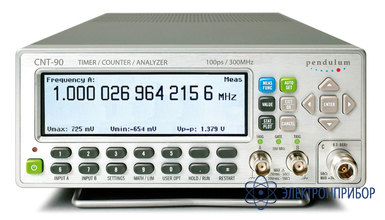
Все товары группы