Lenze руководства, инструкции, брошюры
Инструкции

LENZE 4800 4900 Инструкция
Размер файла: 1.72 мб
Руководство по эксплуатации LENZE 4800 4900
Скачать
Lenze 4800 4900 руководство
Размер файла: 426.50 кб
Руководство по монтажу LENZE 4800 4900
Скачать
lENZE 8200 smd ИНСТРУКЦИЯ
Размер файла: 571.64 кб
Руководство по эксплуатации LENZE 8200 smd
Скачать
LENZE smvector ИНСТРУКЦИЯ
Размер файла: 2.84 мб
Руководство пользователя Lenze smvector
Скачать
lenze 8200 vector инструкция
Размер файла: 2.41 мб
Руководство по эксплуатации Lenze 8200 vector
Скачать
Lenze 8400 инструкция
Размер файла: 4.01 мб
Руководство пользователя lenze 8400
Скачать
lenze 9300 vector инструкция
Размер файла: 657.32 кб
Руководство пользователя Lenze 9300 vector
Скачать
Lenze 9400 инструкция
Размер файла: 7.36 мб
Руководство пользователя lenze 9400 англ.
Скачать
lenze 8200 tmd инструкция
Размер файла: 539.01 кб
Руководство пользователя Lenze 8200 tmd
Скачать

-
Contents
-
Table of Contents
-
Bookmarks
Quick Links
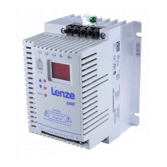
SMD
Frequency Inverter: Basic I/O
Operating Instructions
with CANopen 0.25kW… 4.0kW
Related Manuals for Lenze SMD
Summary of Contents for Lenze SMD
-
Page 1
Frequency Inverter: Basic I/O Operating Instructions with CANopen 0.25kW… 4.0kW… -
Page 2
Lenze AC Tech Corporation. The information and technical data in this manual are subject to change without notice. Lenze AC Tech Corporation makes no warranty of any kind with respect to this material, including, but not limited to, the implied warranties of it’s merchantability and fitness for a given purpose. Lenze AC Tech Corporation assumes no responsibility for any errors that may appear in this manual. -
Page 3: Table Of Contents
Parameter menu …………….13 CANopen mapping details ………….. 23 4.4.1 RPDO mapping details (h66 / h76) ……..23 4.4.2 TPDO mapping details (h86 / h96)……..26 Quick CAN set-up …………….30 Troubleshooting and fault elimination …………31 Lenze 13466185 EDBSW03 v5…
-
Page 4
About these instructions This documentation applies to the smd frequency inverter, and contains important technical data including installation, operation, and commissioning instructions. Please read the instructions in their entirety before commissioning. Type: Input: 1/N/PE (2PE) Output: 3/PE For detailed information… -
Page 5: Safety Information
Safety information General Some parts of Lenze controllers (frequency inverters, servo inverters, DC controllers) can be live, moving and rotating. Some surfaces can be hot. Non-authorized removal of the required cover, inappropriate use, and incorrect installation or operation creates the risk of severe injury to personnel or damage to equipment.
-
Page 6: Pictographs Used In These Instructions
Impending or possible danger Death or injury WARNING! for persons Possible damage to equipment Damage to drive system or its STOP! surroundings Useful tip: If observed, it will Note make using the drive easier Lenze 13466185 EDBSW03 v5…
-
Page 7
Le déclenchement du dispositif de protection du circuit de dérivation peut être dû à une coupure qui résulte d’un courant de défaut. Pour limiter le risque d’incendie ou de choc électrique, examiner les pièces porteuses de courant et les autres éléments du contrôleur et les remplacer s’ils sont endommagés Lenze 13466185 EDBSW03 v5… -
Page 8: Technical Data
(1) For compliance with EMC regulations, the permissible cable lengths may change. (2) The additional measures described only ensure that the controllers meet the requirements of the EN 61000-3-2. The machine/system manufacturer is responsible for the compliance with the regulations of the machine! Lenze 13466185 EDBSW03 v5…
-
Page 9: Ratings
ESMD222W2TXA 11.0 14.4 13.2 ESMD302W2TXA 13.5 12.0 11.0 18.0 16.5 ESMD402W2TXA 17.1 15.2 14.0 22.8 21.0 For rated mains voltage and carrier frequencies 4, 6, 8 kHz For rated mains voltage and carrier frequency 10 kHz Lenze 13466185 EDBSW03 v5…
-
Page 10: Installation
ESMD222W2TXA ESMD302W2TXA ESMD402W2TXA WARNING! Drives must not be installed where subjected to adverse environmental conditions such as: combustible, oily, or hazardous vapors or dust; excessive moisture; excessive vibration or excessive temperatures. Contact Lenze for more information. Lenze 13466185 EDBSW03 v5…
-
Page 11: Electrical Installation
The E.l.c.b can be activated by: capacitive leakage currents between the cable screens during operation (especially with − long, screened motor cables). connecting several controllers to the mains at the same time. − RFI filters − Lenze 13466185 EDBSW03 v5…
-
Page 12: Connection Diagram
• Do not connect mains power to the output terminals (U, V, W)! Severe damage to the drive will result. • Do not cycle mains power more than once every three minutes. Damage to the drive will result. Lenze 13466185 EDBSW03 v5…
-
Page 13: Control Terminals
Installation 3.2.4 Control terminals Data for control connections (printed in bold = Lenze setting) Terminal For reliable communication make sure terminal CAN_GND is connected to CAN network CAN earth ground GND/common. If only two wires are used CAN_GND (CAN_H and CAN_L) in the network, connect CAN_GND to chassis/earth ground.
-
Page 14: Commissioning
An optional EPM Programmer (EEPM1RA) is available that allows: the controller to be programmed without power; OEM settings to be default settings; fast copying of EPMs when multiple controllers require identical settings. It can also store up to 60 custom parameter files for even faster controller programming Lenze 13466185 EDBSW03 v5…
-
Page 15: Parameter Menu
Load Lenze setting No action/loading complete • C02 = 1… 4 only possible with Load 50 Hz Lenze settings • C02 = 2 : C11, C15 = 60.0 Hz, C87 = 1740 RPM, and C89 = 60 Hz Load 60 Hz Lenze settings…
-
Page 16
Motor is running — CW rotation Motor is running — CCW rotation Output frequency = 0 Hz Frequency setpoint reached Threshold (C17) exceeded Current limit reached in either motor or generator mode CANopen Control Output controlled by RPDO (h66,h76 = 4) Lenze 13466185 EDBSW03 v5… -
Page 17
Current limit • When the limit value is reached, either the acceleration time increases or the Reference: smd rated output current output frequency decreases Accel boost 20.0 Accel boost is only active during… -
Page 18
100% = smd rated output current • Correct setting = (motor nameplate current) / (smd output current rating) X 100% • Example: motor = 6.4 amps and smd = 7.0 amps; correct setting = 91% (6.4 / 7.0 = 0.91 x 100% = 91%) NOTE Do not set above the rated motor current as listed on the motor dataplate. -
Page 19
(e.g. SDO, SYNC, PDO…). Message monitoring Not active • h46 = 0 or h47 = 0 disables message time out reaction Inhibit monitoring function Quick stop • h47 is only active when C01 = 3 Trip fault Lenze 13466185 EDBSW03 v5… -
Page 20
= 2: Controller sends “NMT start all nodes” after boot-up time (h55) and enters operational state (not NMT master) These parameters take effect only after power-up, h58 reset, “NMT reset node”, or “NMT reset communication services” Lenze 13466185 EDBSW03 v5… -
Page 21
RPDO#1 time out Not active Only active when C01 = 3 reaction Inhibit Quick stop Trip fault FC3 These parameters take effect only after power-up, h58 reset, “NMT reset node”, or “NMT reset communication services” Lenze 13466185 EDBSW03 v5… -
Page 22
Digital output RPDO#2 status • Read-only • Number of received RPDO#2 messages • Above 255, starts over at 0 These parameters take effect only after power-up, h58 reset, “NMT reset node”, or “NMT reset communication services” Lenze 13466185 EDBSW03 v5… -
Page 23
= 0: disables COS triggering TPDO#1 status • Read-only • Number of transmitted TPDO#1 messages • Above 255, starts over at 0 These parameters take effect only after power-up, h58 reset, “NMT reset node”, or “NMT reset communication services” Lenze 13466185 EDBSW03 v5… -
Page 24
Above 255, starts over at 0 Power up state Quick stop Selects controller power up state when C01 = 3 (CANopen control) Inhibit These parameters take effect only after power-up, h58 reset, “NMT reset node”, or “NMT reset communication services” Lenze 13466185 EDBSW03 v5… -
Page 25: Canopen Mapping Details
Example 2: Requested setpoint = CCW at 44.5 • Direction is set by Bit 2 in WORD0 Hz = — (44.5 x 50) = -2225 = 0xF74F Note: Setpoint sign overrides Bit 2 in WORD0 reserved (not evaluated) reserved (not evaluated) Lenze 13466185 EDBSW03 v5…
-
Page 26
Example 2 (C87 = 1390 RPM, C89 = 50 Hz): Requested setpoint CCW 44.5 Hz = — (44.5 x 1390/50) = — 1237 = 0xFB2B Implemented as inhibit; all indicated bits must be in opposite state for controller to be enabled. Lenze 13466185 EDBSW03 v5… -
Page 27
Note: Setpoint sign overrides Bit 2 in WORD0 Digital outputs (RELAY + E3) • Bit 0 — RELAY — (if C08 set to selection 9) • Bit 1 — E3 (if CE3 set to selection 30) reserved (not evaluated) Lenze 13466185 EDBSW03 v5… -
Page 28: Tpdo Mapping Details (H86 / H96)
Example: CW at 34.5 Hz = 34.5 x 10 = 345 = 0x06BD 0x0159 • Example 2: CCW at 44.5 Hz = — (44.5 x 50) = — • Direction is indicated by bit 14 in WORD0 2225 = 0xF74F reserved reserved Lenze 13466185 EDBSW03 v5…
-
Page 29
Example: CW at 34.5 Hz = 34.5 x 10 = 345 = 0x06BD 0x0159 • Example 2: CCW at 44.5 Hz = — (44.5 x 50) = — • Direction is indicated by bit 2 in WORD0 2225 = 0xF74F reserved reserved Lenze 13466185 EDBSW03 v5… -
Page 30
1 = Quick stop not active 1 = Quick stop not active Switch on disabled Switch on disabled On smd controller this is always 0 On smd controller this is always 0 (switch on enabled) (switch on enabled) 0 = No warning… -
Page 31
Bit 0 — TB28 state (1 — asserted) • Bit 1 — E1 state (1 — asserted) • Bit 2 — E2 state (1 — asserted) • Bit 3 — E3 state (1 — asserted) reserved Lenze 13466185 EDBSW03 v5… -
Page 32: Quick Can Set-Up
After these controllers are configured as above, controller #2 will follow the operation of controller #1 including: Inhibit state, Quick Stop, DC brake, JOG speed selections, direction, and speed. For additional safety, controller #2 will transition to inhibit state if valid PDO is not received from controller #1 within 50ms. Lenze 13466185 EDBSW03 v5…
-
Page 33: Troubleshooting And Fault Elimination
Remedy Data not valid for controller • Use EPM providing valid data Data error Data on EPM not valid • Load Lenze setting OEM data not valid EPM error EPM missing or defective Power down and replace EPM Digital inputs not E1…E3 assigned with the same…
-
Page 34
If power is removed when the drive is in an “OC6” fault state, when the power is restored the “OC6” fault will still be present and the delay will still be active even if power was removed for longer than 3 minutes. Lenze 13466185 EDBSW03 v5… -
Page 36
Lenze 13466185 EDBSW03 v5 EN Lenze Americas Corporation 630 Douglas Street Uxbridge, MA 01569 800 217-9100 508 278-7873 marketing@lenzeamericas.com www.Lenze.com Service Lenze AC Tech Corporation 630 Douglas Street Uxbridge, MA 01569 508 278-9100 508 278-6620 repair@lenzeamericas.com…
Новости
18
09.23
Встречайте новый каталог российских индикаторов потока
11
09.23
Промышленные блоки питания для экстремальных условий
07
09.23
Стойкие к кислым средам кабельные датчики уровня
04
09.23
Пирометры с возможностью выбора схемы подключения
28
08.23
Измерение уровня жидкостей, агрессивных и нейтральных