-
Contents
-
Table of Contents
-
Troubleshooting
-
Bookmarks
Quick Links
Cat. No. I011-E1-3
USER’S MANUAL
SYSDRIVE 3G3EV
(Standard Models)
Compact Low-noise Inverter
Related Manuals for Omron SYSDRIVE 3G3EV
Summary of Contents for Omron SYSDRIVE 3G3EV
-
Page 1
Cat. No. I011-E1-3 USER’S MANUAL SYSDRIVE 3G3EV (Standard Models) Compact Low-noise Inverter… -
Page 2
Thank you for choosing this SYSDRIVE 3G3EV-series product. Proper use and handling of the product will ensure proper product performance, will length product life, and may prevent possible accidents. Please read this manual thoroughly and handle and operate the product with care. -
Page 3: Table Of Contents
Table of Contents Chapter 1. Getting Started ……Items to be Checked when Unpacking ……Precautions .
-
Page 4
Table of Contents Chapter 5. Operation ……Protective and Diagnostic Functions . -
Page 5: Chapter 1. Getting Started
Chapter 1 Getting Started 1-1 Items to be Checked when Unpacking 1-2 Precautions…
-
Page 6: Items To Be Checked When Unpacking
1-1 Items to be Checked when Unpacking H Checking the Product On delivery, always check that the delivered product is the SYSDRIVE 3G3EV Inverter that you ordered. Should you find any problems with the product, immediately contact your nearest local sales representative.
-
Page 7: Precautions
Chapter 1 Getting Started Voltage Class Special Specification Three-phase 200-VAC input English Models Single/Three-phase 200-VAC -CUE UL/CUL and EC Directives input Models Blank Japanese Models Installation Type/Option Panel mounting Option D Checking for Damage Check the overall appearance and check for damage or scratches resulting from trans- portation.
-
Page 8
Chapter 1 Getting Started If an inspection or some other task is to be performed, always wait at least one minute from the time all indicators on the front panel go off. (Note that this warning is applicable whenever you perform any task after turning the main circuit off.) H Do Not Remove the Digital Operator When the Main Circuit is Still On. -
Page 9: Chapter 2. Overview
Chapter 2 Overview 2-1 Features 2-2 Component Names…
-
Page 10: Features
Chapter 2 Overview 2-1 Features H Easy to Use D Basic Constants Displayed On Indicators Constants for basic operations such as frequency setting and acceleration/deceleration time setting are displayed on dedicated indicators. Therefore, constant numbers can be confirmed easily. D Minimum Constant Setting Items Constant setting items have been minimized to enable even first-time users to set constants easily.
-
Page 11
Chapter 2 Overview H Easy to Wire D Easy Wiring without Having to Open the Front Cover This Inverter can be wired just by opening the terminal block cover. D Separate Input and Output Terminal Blocks Power input terminals are located in the upper section, while motor output terminals are in the lower section. -
Page 12: Component Names
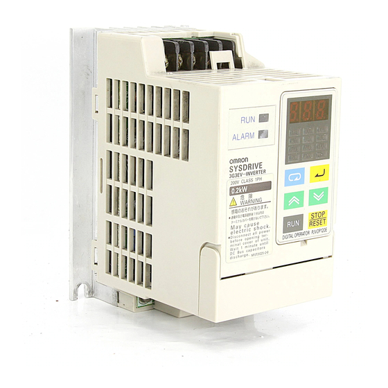
Chapter 2 Overview 2-2 Component Names H Main Unit Main Circuit Terminals (Input) Power input Braking resistor terminals connection terminals L1 N/L2 L3 Run indicator Digital Operator Alarm indicator Control circuit terminals Control circuit (output) terminals (input) SF SR S1 SC FS FR FC Ground terminal Motor output terminals…
-
Page 13: Digital Operator
Chapter 2 Overview H Digital Operator Data display section Monitor item indicators In-service item indicators (green indicators) Display These items can be monitored or set even section during operation. Stopped item indicators (red indicators) These items can be set only when the Inverter is stopped.
-
Page 14: Chapter 3. Design
Chapter 3 Design 3-1 Installation 3-2 Wiring…
-
Page 15: Installation
Chapter 3 Design 3-1 Installation 3-1-1 Outside/Mounting Dimensions Note All dimensions are in millimeters. H 3G3EV-A2001(-j) to 3G3EV-A2004(-j) (0.1 to 0.4 kW): Three-phase 200-VAC Input H 3G3EV-AB001(-j) to 3G3EV-AB002(-j) (0.1 to 0.2 kW): Single/Three-phase 200-VAC Input 4.5 dia. Note 1. For the 3G3EV-A2001(-j), 3G3EV-A2002(-j), and 3G3EV-AB001(-j), a U- shaped notch (4.5 mm wide) is provided instead of the upper mounting hole (4.5 mm in diameter).
-
Page 16
Chapter 3 Design D Three-phase 200-VAC Input Model 3G3EV Output Weight model (kg) A2001(-j) 0.1 kW Approx. A2002(-j) 0.2 kW Approx. A2004(-j) 0.4 kW Approx. D Single/Three-phase 200-VAC Input Model 3G3EV Output Weight model (kg) AB001(-j) 0.1 kW Approx. AB002(-j) 0.2 kW Approx. -
Page 17: Installation Conditions
Chapter 3 Design Note Install the Inverter with four M4 bolts. D Three-phase 200-VAC Input Model 3G3EV Output Weight (kg) model A2007(-j) 0.75 kW Approx. 1.3 A2015(-j) 1.5 kW Approx. 1.5 D Single/Three-phase 200-VAC Input Model 3G3EV Output Weight model (kg) 0.4 kW Approx.
-
Page 18
Chapter 3 Design •Install the Inverter in a clean location free from oil mist and dust. Alternatively, install it in a totally enclosed panel that is completely shielded from suspended dust. •When installing or operating the Inverter, always take special care so that metal pow- der, oil, water, or other foreign matter do not get in the Inverter. -
Page 19: Wiring
Chapter 3 Design 3-2 Wiring 3-2-1 Terminal Blocks H Name of Each Terminal Block Main Circuit Terminals (Input) Power input Braking resistor terminals connection terminals Control circuit terminals (output) Control circuit terminals (input) SF SR S1 SC FS FR FC Ground Main circuit terminals terminal…
-
Page 20: Main Circuit Terminals
Chapter 3 Design H Main Circuit Terminals D Input Terminals (Top Section) Terminal Name and description symbol R (L1) Power input terminals A2j: Three-phase 200 to 230 VAC, 50/60 Hz A2j: Three-phase 200 to 230 VAC, 50/60 Hz S (L2/N) ABj: Single-phase 200 to 240 VAC, 50/60 Hz Three-phase 200 to 230 VAC, 50/60 Hz A4j: Three-phase 380 to 460 VAC, 50/60 Hz…
-
Page 21: Control Circuit Terminals
Chapter 3 Design H Control Circuit Terminals D Input Terminals (On Right-hand Side) No external power supply is required because a built-in power supply is provided. Terminal Name and description Interface symbol Forward/Stop When the terminal is ON, the motor rotates in the forward direction.
-
Page 22: Standard Connection Diagram
Chapter 3 Design D Output Terminals (On Left-hand Side) Terminal Name and description Interface symbol Multi-function contact output (contact a) (see note) Multi-function contact output (contact b) 30 VDC (see note) 250 VAC Multi-function contact output (common) Note Constant No. 09 (n09) is used to set the function. This constant is factory set to “operation in progress.”…
-
Page 23: Wiring Around The Main Circuit
Chapter 3 Design Note 1. If a 3G3EV-ABjjj is used in single-phase input mode, single-phase 200 to 240 VAC power with a frequency of 50/60 Hz must be input between terminals R and S. Note 2. For the 3-wire sequence, refer to the wiring on page 4-12. Note 3.
-
Page 24
Chapter 3 Design Determining the Wire Size Determine the wire size for the main circuit so that line voltage drop is within 2% of the rated voltage. Line voltage drop V is calculated as follows: –3 (V) = 3 x wire resistance (Ω/km) x wire length (m) x amperage (A) x 10 H Wiring on the Input Side of Main Circuit D Installing a Molded-case Circuit Breaker Always connect the power input terminals (R, S, and T) and power supply via a molded-… -
Page 25
Chapter 3 Design D Installing an AC Reactor If the Inverter is connected to a large-capacity power transformer (600 kW or more) or the phase advance capacitor is switched, an excessive peak current may flow through the input power circuit, causing the converter unit to break down. To prevent this, install an optional AC reactor on the input side of the Inverter. -
Page 26
Chapter 3 Design D Installing a Noise Filter on the Power Supply Side Install a noise filter to eliminate noise transmitted between the power line and the Inverter. Wiring Example 1 Power 3G3IV-PHF 3G3EV supply Noise filter SYSMAC, etc. Other controllers Note Use a special-purpose noise filter for Inverters. -
Page 27
Chapter 3 Design D Never Connect Power Supply to Output Terminals Caution Never connect a power supply to output terminals U, V, and W. If voltage is applied to the output terminals, the internal mechanism of the Inverter will be damaged. D Never Short or Ground the Output Terminals Caution If the output terminals are touched with bare hands or the output wires come into contact with the Inverter casing, an electric shock or grounding will occur. -
Page 28
Chapter 3 Design Induction Noise: Electromagnetic induction generates noise on the signal line, causing the controller to malfunction. Radio Noise: Electromagnetic waves from the Inverter and cables cause the broadcasting radio receiver to make noise. D How to Prevent Induction Noise As described above, a noise filter can be used to prevent induction noise from being generated on the output side. -
Page 29: Ground Wiring
Chapter 3 Design D Cable Length between Inverter and Motor If the cable between the Inverter and the motor is long, the high-frequency leakage cur- rent will increase, causing the Inverter output current to increase as well. This may affect peripheral devices.
-
Page 30: Wiring Control Circuit Terminals
Chapter 3 Design 3-2-3 Wiring Control Circuit Terminals The control signal line must be 50 m or less and must be separated from the power line. If frequency references are input externally, use a twisted- pair shielded line. H Wiring Sequence Input/Output Terminals Wire the sequence input terminals (SF, SR, S1, and SC) and the multi-function contact output terminals (MA, MB, and MC) as described below.
-
Page 31
Chapter 3 Design D Wires to be Used Always use twisted-pair shielded wires to prevent malfunctions due to noise. Wire type Wire size Wire to be used Single wire 0.5 to 1.25 mm Polyethylene-insulated cable for instrumentation (with shield) Stranded wire 0.5 to 1.25 mm D Wiring Method •The wiring procedure is the same as for sequence input/output terminals, described… -
Page 32: Chapter 4. Preparing For Operation
Chapter 4 Preparing for Operation 4-1 Preparation Procedure 4-2 Using the Digital Operator 4-3 Test Run…
-
Page 33: Preparation Procedure
Chapter 4 Preparing for Operation 4-1 Preparation Procedure 1. Installation: Install the Inverter according to installation conditions. Refer to page 3-2 Check that all the installation conditions are met. 2. Wiring: Connect the Inverter to power supply and peripheral devices. Refer to page 3-6 Select peripheral devices that meet the specifications, and wire them correctly.
-
Page 34: Using The Digital Operator
Chapter 4 Preparing for Operation 6. Test Run: Perform a no-load test run and an actual loading test run to check that the motor and peripheral devices operate normally. Refer to page 4-25 Check the direction of motor rotation and check that the limit switches operate nor- mally.
-
Page 35
Chapter 4 Preparing for Operation H Function of Each Component D Display Sections Data display section Reference frequency values, output frequency values, output current values, constant settings, and error codes are displayed. Monitor item indicators When this indicator is lit, an output frequency value (Hz) is displayed in the data display section. -
Page 36: Outline Of Operation
Chapter 4 Preparing for Operation 4-2-2 Outline of Operation H Switching Data Display during Operation Press the Mode Key to switch data display. During operation, only the items in the in-service item indicators section can be monitored and the constants for these items can be set. If the power is turned off when the FOUT or IOUT indicator is lit, the same indicator lights up next time the power is turned on.
-
Page 37
Chapter 4 Preparing for Operation H Switching Data Display when Inverter is Stopped Press the Mode Key to switch data display. When the Inverter is stopped, all items can be monitored and the constant for each item can be set. Example Indi- Description… -
Page 38
Chapter 4 Preparing for Operation H Monitor Display The 3G3EV allows the user to monitor the reference frequency, output fre- quency, output current, and the direction of rotation. D Operation Method Indicator Example of Description operation data display 60.0 Press the Mode Key until the FREF indicator lights up. -
Page 39: Setting Constants
Chapter 4 Preparing for Operation 4-2-3 Setting Constants The 3G3EV (Standard Model) allows the user to set 18 different constants. The constants for basic operations are allocated to dedicated indicators, so the user need not refer to the constant nos. The constants allocated to dedicated indicators can be also set by lighting the PRGM indicator.
-
Page 40
Chapter 4 Preparing for Operation D Setting Constants Using the PRGM Indicator Example: Changing the value of constant no. 02 (operation mode selection) to “2.” Indicator Example of Explanation operation data display Press the Mode Key until the PRGM indicator lights up. -
Page 41
Chapter 4 Preparing for Operation H List of Constants Constant Dedicated Description Setting range Factory setting indicator Constant write-inhibit selec- 0, 1, 8, 9 tion/constant initialization Operation mode selection 0 to 5 Interruption mode selection 0, 1 Forward/reverse rotation For, rEv selection Multi-function input selec- 0 to 4… -
Page 42
Chapter 4 Preparing for Operation Note 3. The setting range for the 400-VAC models is “1 to 5.” Note 4. The factory setting for the 3G3EV-A4015-CUE is “3.” Note 5. Displaying the constant no. corresponding to an indicator in the “Dedicated indicator”… -
Page 43
Chapter 4 Preparing for Operation Example of 3-wire Sequence Mode Stop switch switch (contact b) (contact a) Run command (starts Inverter when “closed”) Stop command (stops Inverter when “opened”) Forward/Reverse rotation command (rotates motor in forward direction when “opened”; rotates motor in reverse direction when “closed”) Common Example of Operation Forward rotation… -
Page 44
Chapter 4 Preparing for Operation Note 2. The DIP switch is located inside the Inverter. Use this switch to change the set- ting when frequency references are to be input in terms of amperage (4 to 20 mA). For details, refer to Section 7-2 Frequency Reference by Amperage Input. For voltage input, never set the DIP switch to ON. -
Page 45
Chapter 4 Preparing for Operation Forward/Reverse Rotation Selection f%r , reU Factory setting f%r Setting range (forward rota- tion) This constant is used to specify the direction of motor rotation when the Inverter is oper- ated with the Digital Operator. Value Description Forward rotation… -
Page 46
Chapter 4 Preparing for Operation Note MA is turned on when the difference between the reference frequency and the output frequency falls within 2 Hz. MA is turned off when the difference exceeds ±4 Hz. Example of Operation Reference frequency Detection range ±2 Hz Release range… -
Page 47
Chapter 4 Preparing for Operation Frequency Reference 1 Setting range 0.0 to 400 (Hz) Factory setting 6.0 (Hz) Frequency Reference 2 Setting range 0.0 to 400 (Hz) Factory setting 0.0 (Hz) •These constants are used to set reference frequency values. •The unit of setting is as follows: 0.0 to 99.9 (Hz): 0.1 (Hz) 100 to 400 (Hz): 1 (Hz) -
Page 48
Chapter 4 Preparing for Operation Acceleration Time Setting range 0.0 to 999 Factory setting 10.0 (seconds) (seconds) Deceleration time Setting range 0.0 to 999 Factory setting 10.0 (seconds) (seconds) •These constants are used to set acceleration time (required to increase the output fre- quency from the stopped state to the maximum frequency) and deceleration time (re- quired to decrease the output frequency from the maximum frequency to the stopped state). -
Page 49
Chapter 4 Preparing for Operation Maximum Frequency Setting range 50.0 to 400 Factory setting 60.0 (Hz) (Hz) Unit of setting 50.0 to 99.9 (Hz) : 0.1 (Hz) 100 to 400 (Hz) : 1 (Hz) Maximum Voltage Setting range 1 to 255 (510) Factory setting 200 (400) (V) Unit of setting 1 (V) Maximum Voltage Frequency (Basic Frequency) -
Page 50
Chapter 4 Preparing for Operation Electronic Thermal Reference Current Setting range 0.0 to Factory setting See note 2 (see note 1) (A) Unit of setting 0.1 (A) •This constant is used to set an electronic thermal reference value to protect the motor from overheating. -
Page 51
Chapter 4 Preparing for Operation Operation after Recovery from Power Interruption Setting range 0, 1, 2 Factory setting 0 This constant is used to select the processing to be performed after recovery from an instantaneous power interruption. Value Description Discontinues operation. Continues operation only if power interruption is within 0.5 second. -
Page 52
Chapter 4 Preparing for Operation Note 2. The factory setting for the 3G3EV-A4015-CUE is “3.” Note 3. With the 400-VAC class, the continuous output current cannot be used to 100% of the rated value if the constant is set to “5” for Inverters of 0.75 kW or less or if it is set to “4”… -
Page 53
Chapter 4 Preparing for Operation Frequency Reference Gain Setting range 0.10 to 2.55 Factory setting 1.00 (times) (times) Unit of setting 0.01 (times) Frequency Reference Bias Setting range –99 to 99 (%) Factory setting 0 (%) Unit of setting 1 (%) •These constants are used to set the relationship between analog voltage and refer- ence frequencies when frequency references are input through control terminals FR and FC. -
Page 54
Chapter 4 Preparing for Operation Stop Key Selection Setting range 0, 1 Factory setting 0 •When inputting Inverter operation from the control terminals, the Stop Key on the Digi- tal Operator can be set to “enabled” or “disabled.” Value Description Stop Key enabled Stop Key disabled Note 1. -
Page 55
Chapter 4 Preparing for Operation •Recorded are Inverter errors and other errors that actuate a protective mechanism. Warning (automatically recovered error) is not recorded. •If no error has occurred, the indicator is not lit. •All error codes are listed below. Error code Description Error category… -
Page 56: Test Run
Chapter 4 Preparing for Operation 4-3 Test Run After wiring is complete, perform a test run of the Inverter as follows. First, start the motor through the Digital Operator without connecting the motor to the mechanical system. Next, connect the motor to the mechanical sys- tem and perform a test run.
-
Page 57: Setting Rated Motor Amperage
Chapter 4 Preparing for Operation 4-3-5 Setting Rated Motor Amperage •Set the rated motor amperage in constant no. 31 (electronic thermal reference current) or with the “THR” indicator lit. 4-3-6 Setting the Reference Frequency •Set the frequency corresponding to the motor speed in constant no. 11 (frequency ref- erence 1) or with the “FREF”…
-
Page 58: Chapter 5. Operation
Chapter 5 Operation 5-1 Protective and Diagnostic Functions 5-2 Troubleshooting 5-3 Maintenance and Inspection…
-
Page 59: Protective And Diagnostic Functions
Chapter 5 Operation 5-1 Protective and Diagnostic Functions The 3G3EV has excellent protective and diagnostic functions. The RUN and ALARM indicators on the front panel indicate the current Inverter sta- tus, and the data display section also displays information about an error that has occurred.
-
Page 60
Chapter 5 Operation H Data Display and Action to be Taken when Warning Status Arises The ALARM indicator flashes when warning status arises. The data display section also flashes. When warning status arises, no error code is output. Eliminating the cause recovers the system automatically. Data Description Action… -
Page 61
Chapter 5 Operation H Data Display and Action to be Taken when Protective Mechanism is Actuated The ALARM indicator lights up when the protective mechanism is actuated. In this event, Inverter output is shut off, and the motor coasts to a stop. Check the cause of the error, take the necessary action, and perform fault reset or turn the power off, then on. -
Page 62
Chapter 5 Operation Data Description Cause and action display • The input power voltage dropped. Main circuit undervoltage (UV1) • Open-phase occurred. The DC voltage of the main circuit dropped below the specified level. • An instantaneous power interruption 3G3EV-A2jjj: Approximately 200 V occurred. -
Page 63
Chapter 5 Operation Data Description Cause and action display • Review the load size, V/f characteris- Motor overload (OL1) tics, acceleration/deceleration time, The electronic thermal relay actuated and cycle time. the motor overload protection function. • Set the rated motor amperage in constant No. -
Page 64
Chapter 5 Operation H Data Display and Action to be Taken when Inverter Error Occurs The first character of an error code is always “F” when an Inverter error occurs. (Howev- er, all indicators are not lit when a control circuit error occurs.) If an Inverter error occurs, turn the power off, then on. -
Page 65: Troubleshooting
Chapter 5 Operation 5-2 Troubleshooting If the Inverter or motor does not operate properly when the system is started, constant settings or wiring may be incorrect. In this case, take the appropriate action as described below. (If an error code is displayed, refer to 5-1 Protective and Diagnostic Functions.) 5-2-1 Constants Fail to Set H err is Displayed in the Data Display Section.
-
Page 66: Motor Rotates In The Wrong Direction
Chapter 5 Operation •The reference frequency is too low. When the reference frequency is less than 1.5 Hz, the Inverter cannot operate. Change the reference frequency to 1.5 Hz or more. •The sequence input method is wrong. If the 3-wire sequence input mode is selected as an external terminal function instead of the actual 2-wire sequence input mode, the motor will not run, in which case change the constant or change to the sequence input that matches the constant setting.
-
Page 67: Motor Deceleration Is Too Slow
Chapter 5 Operation To reverse the direction of rotation, switch the wires of two phases of U, V, and W as shown below. Inverter Motor Forward rotation Reverse rotation 5-2-4 Motor Deceleration is Too Slow H Deceleration Time is Too Long Even if a Braking Resistor is Connected.
-
Page 68: Motor Burns
Chapter 5 Operation 5-2-6 Motor Burns •The dielectric strength of the motor is insufficient. Surge arises when the motor (inductive load) is connected to the output side of the Inverter. Normally, the maximum surge voltage is approximately three times the power voltage.
-
Page 69: Mechanical System Makes Noise
Chapter 5 Operation S Install an input noise filter. Install an input noise filter (3G3IV-PHF) on the power input side of the Inverter. S Install an output noise filter. Install an output noise filter (3G3IV-PLF) on the output side of the Inverter. S Use metal box and piping.
-
Page 70: Maintenance And Inspection
Chapter 5 Operation Under the wiring condition shown below, if the control output power supply is lower than 24 VDC or if it is set to OFF, current may flow in the direction shown by the arrows and may operate the Inverter input. In such a case, insert a diode in the A section shown below.
-
Page 71
Chapter 5 Operation H Regular Maintenance Check the items below during regular maintenance. Before starting inspection, always turn the power off, then wait at least one minute after all indicators on the front panel go off. Touching terminals immediately after turning the power off may cause an electrical shock. -
Page 72: Chapter 6. Specifications
Chapter 6 Specifications 6-1 Specifications of Main Unit…
-
Page 73
Chapter 6 Specifications 6-1 Specifications of Main Unit H Rating Model 3G3EV- A2001(-j) A2002(-j) A2004(-j) A2007(-j) A2015(-j) Three phase, Power Rated voltage Three-phase, 200 to 230 VAC, 50/60 Hz 200 VAC supply and frequency Allowable –15% to 10 % voltage fluctuation ±5% Allowable… -
Page 74: General Specifications
Chapter 6 Specifications Model 3G3EV- Three A4002(-j) A4004(-j) A4007(-j) A4015(-j) phase, Power Rated voltage Three-phase, 380 to 460 VAC, 50/60 Hz 400 VAC supply and frequency Allowable –15% to 10 % voltage fluctuation ±5% Allowable frequency fluctuation Heating value (W) 25.5 34.7 56.0…
-
Page 75
Chapter 6 Specifications H Control Characteristics Control method Sine-wave PWM method (automatic torque boost) Frequency control 1.5 to 400 Hz range Frequency accuracy Digital command: ±0.01% (–10°C to 50°C) (temperature fluctuation) Analog command: ±1% (25 ±10°C) Frequency setting Digital command: resolution 0.1 Hz (less than 100 Hz), 1 Hz (100 Hz or more) Analog command:… -
Page 76: Protection Functions
Chapter 6 Specifications H Protection Functions Motor protection Electronic thermal protection Instantaneous When 250% of the rated output amperage is exceeded overcurrent protection Overload protection When 150% of the rated output amperage is exceeded for one minute Overvoltage protection Stops the system when DC voltage of the main circuit exceeds approximately 410 V (400-VAC Class approximately 820 V) Voltage drop protection 3G3EV-A2jjj: Stops the system when voltage drops below approximately 200 V…
-
Page 77
Chapter 6 Specifications H Operation Specifications Three photocoupler input terminals (24 VDC, 8 mA) Control input • Forward/stop [SF] • Reverse/stop [SR] • Multi-function input [S1] (set in constant No. 06) Select either of “fault reset,” “external fault,” and “multi-step speed command.”… -
Page 78: Chapter 7. Appendix A
Chapter 7 Appendix A 7-1 Notes on Using Inverter for Motor 7-2 Frequency Reference by Amperage Input 7-3 List of Product Models…
-
Page 79: Notes On Using Inverter For Motor
Chapter 7 Appendix A 7-1 Notes on Using Inverter for Motor H Using Inverter for Existing Standard Motor When a standard motor is operated with this Inverter, a power loss is slightly higher than when operated with a commercial power supply. In addition, cooling effects also decline in the low-speed range, resulting in an increase in the motor temperature.
-
Page 80
Chapter 7 Appendix A D Vibration The 3G3EV series employs high carrier PWM control to reduce motor vibration. When the motor is operated with this Inverter, motor vibration is almost the same as when op- erated with a commercial power supply. However, motor vibration may become greater in the following cases: •Resonance with the natural frequency of mechanical system Take special care when a machine that has been operated at a constant speed is to… -
Page 81: Frequency Reference By Amperage Input
Chapter 7 Appendix A D Gearmotor The speed range for continuous operation differs according to the lubrication method and motor manufacturer. In particular, continuous operation of an oil-lubricated motor in the low speed range may result in burning. If the motor is to be operated at a speed high- er than 60 Hz, consult with the manufacturer.
-
Page 82
Chapter 7 Appendix A 3. Removing the Digital Operator S Insert a finger in the recessed section below the Digital Operator, then lift the under- neath of the Digital Operator. S When the connector comes off, grip the lower edges of the Digital Operator, and slide it down until it comes off. -
Page 83
Chapter 7 Appendix A “SW1” is marked near the switch. Switch indicator V: Voltage input I: Amperage input DIP switch 5. Changing the DIP switch setting To use amperage input mode, set this switch to ON by sliding it to the right. (factory setting) 6. -
Page 84: List Of Product Models
Chapter 7 Appendix A 7-3 List of Product Models H Inverter Specifications Model Standard Three-phase 200 VAC input 0.1 kW 3G3EV-A2001(-j) models 0.2 kW 3G3EV-A2002(-j) 0.4 kW 3G3EV-A2004(-j) 0.75 kW 3G3EV-A2007(-j) 1.5 kW 3G3EV-A2015(-j) Single/Three-phase 200 VAC input 0.1 kW 3G3EV-AB001(-j) 0.2 kW 3G3EV-AB002(-j)
-
Page 85: Output Noise Filter
Chapter 7 Appendix A H Braking Resistor (Duty Cycle 3% ED) Specifications Model 400 Ω 200-VAC class 0.1 kW/0.2 kW 3G3IV-PERF150WJ401 200 Ω 0.4 kW/0.75 kW 3G3IV-PERF150WJ201 100 Ω 1.5 kW 3G3IV-PERF150WJ101 750 Ω 400-VAC class 0.75 kW or less 3G3IV-PERF150WJ751 400 Ω…
-
Page 86
Chapter 7 Appendix A H DIN Track Specifications Model 3G3EV-A2001(-j) to 3G3EV-A2004(-j) 3G3EV-PSPAT3 3G3EV-AB001(-j) and 3G3EV-AB002(-j) 3G3EV-A2007(-j) to 3G3EV-A2015(-j) 3G3EV-PSPAT4 3G3EV-AB004(-j) and 3G3EV-AB007(-j) 3G3EV-A4002(-j) to 3G3EV-A4007(-j) -
Page 87
Chapter 7 Appendix A List of Constants Used with 3G3EV Standard Model Constant Indi- Description Setting range Setting cators Constant 0: Only n01 can be set. write-inhibit 1: All constants can be set. selection 8: Constant settings are initialized. /constant 9: Inverter is initialized in 3-wire initialization sequence mode. -
Page 88
Chapter 7 Appendix A Constant Indi- Description Setting range Setting cators Deceleration 0.0 to 999 (seconds) [10.0] time Maximum 50.0 to 400 (Hz) [60.0] frequency Maximum 1 to 255 (V) (see note 1) [200] voltage Maximum 1.6 to 400 (Hz) [60.0] voltage frequency (basic…
This manual is also suitable for:
Sysdrive 3g3ev series
-
Page 1
Cat. No. I011-E1-3 USER’S MANUAL SYSDRIVE 3G3EV (Standard Models) Compact Low-noise Inverter… -
Page 2
Thank you for choosing this SYSDRIVE 3G3EV-series product. Proper use and handling of the product will ensure proper product performance, will length product life, and may prevent possible accidents. Please read this manual thoroughly and handle and operate the product with care. -
Page 3: Table Of Contents
Table of Contents Chapter 1. Getting Started ……Items to be Checked when Unpacking ……Precautions .
-
Page 4
Table of Contents Chapter 5. Operation ……Protective and Diagnostic Functions . -
Page 5: Chapter 1. Getting Started
Chapter 1 Getting Started 1-1 Items to be Checked when Unpacking 1-2 Precautions…
-
Page 6: Items To Be Checked When Unpacking
1-1 Items to be Checked when Unpacking H Checking the Product On delivery, always check that the delivered product is the SYSDRIVE 3G3EV Inverter that you ordered. Should you find any problems with the product, immediately contact your nearest local sales representative.
-
Page 7: Precautions
Chapter 1 Getting Started Voltage Class Special Specification Three-phase 200-VAC input English Models Single/Three-phase 200-VAC -CUE UL/CUL and EC Directives input Models Blank Japanese Models Installation Type/Option Panel mounting Option D Checking for Damage Check the overall appearance and check for damage or scratches resulting from trans- portation.
-
Page 8
Chapter 1 Getting Started If an inspection or some other task is to be performed, always wait at least one minute from the time all indicators on the front panel go off. (Note that this warning is applicable whenever you perform any task after turning the main circuit off.) H Do Not Remove the Digital Operator When the Main Circuit is Still On. -
Page 9: Chapter 2. Overview
Chapter 2 Overview 2-1 Features 2-2 Component Names…
-
Page 10: Features
Chapter 2 Overview 2-1 Features H Easy to Use D Basic Constants Displayed On Indicators Constants for basic operations such as frequency setting and acceleration/deceleration time setting are displayed on dedicated indicators. Therefore, constant numbers can be confirmed easily. D Minimum Constant Setting Items Constant setting items have been minimized to enable even first-time users to set constants easily.
-
Page 11
Chapter 2 Overview H Easy to Wire D Easy Wiring without Having to Open the Front Cover This Inverter can be wired just by opening the terminal block cover. D Separate Input and Output Terminal Blocks Power input terminals are located in the upper section, while motor output terminals are in the lower section. -
Page 12: Component Names
Chapter 2 Overview 2-2 Component Names H Main Unit Main Circuit Terminals (Input) Power input Braking resistor terminals connection terminals L1 N/L2 L3 Run indicator Digital Operator Alarm indicator Control circuit terminals Control circuit (output) terminals (input) SF SR S1 SC FS FR FC Ground terminal Motor output terminals…
-
Page 13: Digital Operator
Chapter 2 Overview H Digital Operator Data display section Monitor item indicators In-service item indicators (green indicators) Display These items can be monitored or set even section during operation. Stopped item indicators (red indicators) These items can be set only when the Inverter is stopped.
-
Page 14: Chapter 3. Design
Chapter 3 Design 3-1 Installation 3-2 Wiring…
-
Page 15: Installation
Chapter 3 Design 3-1 Installation 3-1-1 Outside/Mounting Dimensions Note All dimensions are in millimeters. H 3G3EV-A2001(-j) to 3G3EV-A2004(-j) (0.1 to 0.4 kW): Three-phase 200-VAC Input H 3G3EV-AB001(-j) to 3G3EV-AB002(-j) (0.1 to 0.2 kW): Single/Three-phase 200-VAC Input 4.5 dia. Note 1. For the 3G3EV-A2001(-j), 3G3EV-A2002(-j), and 3G3EV-AB001(-j), a U- shaped notch (4.5 mm wide) is provided instead of the upper mounting hole (4.5 mm in diameter).
-
Page 16
Chapter 3 Design D Three-phase 200-VAC Input Model 3G3EV Output Weight model (kg) A2001(-j) 0.1 kW Approx. A2002(-j) 0.2 kW Approx. A2004(-j) 0.4 kW Approx. D Single/Three-phase 200-VAC Input Model 3G3EV Output Weight model (kg) AB001(-j) 0.1 kW Approx. AB002(-j) 0.2 kW Approx. -
Page 17: Installation Conditions
Chapter 3 Design Note Install the Inverter with four M4 bolts. D Three-phase 200-VAC Input Model 3G3EV Output Weight (kg) model A2007(-j) 0.75 kW Approx. 1.3 A2015(-j) 1.5 kW Approx. 1.5 D Single/Three-phase 200-VAC Input Model 3G3EV Output Weight model (kg) 0.4 kW Approx.
-
Page 18
Chapter 3 Design •Install the Inverter in a clean location free from oil mist and dust. Alternatively, install it in a totally enclosed panel that is completely shielded from suspended dust. •When installing or operating the Inverter, always take special care so that metal pow- der, oil, water, or other foreign matter do not get in the Inverter. -
Page 19: Wiring
Chapter 3 Design 3-2 Wiring 3-2-1 Terminal Blocks H Name of Each Terminal Block Main Circuit Terminals (Input) Power input Braking resistor terminals connection terminals Control circuit terminals (output) Control circuit terminals (input) SF SR S1 SC FS FR FC Ground Main circuit terminals terminal…
-
Page 20: Main Circuit Terminals
Chapter 3 Design H Main Circuit Terminals D Input Terminals (Top Section) Terminal Name and description symbol R (L1) Power input terminals A2j: Three-phase 200 to 230 VAC, 50/60 Hz A2j: Three-phase 200 to 230 VAC, 50/60 Hz S (L2/N) ABj: Single-phase 200 to 240 VAC, 50/60 Hz Three-phase 200 to 230 VAC, 50/60 Hz A4j: Three-phase 380 to 460 VAC, 50/60 Hz…
-
Page 21: Control Circuit Terminals
Chapter 3 Design H Control Circuit Terminals D Input Terminals (On Right-hand Side) No external power supply is required because a built-in power supply is provided. Terminal Name and description Interface symbol Forward/Stop When the terminal is ON, the motor rotates in the forward direction.
-
Page 22: Standard Connection Diagram
Chapter 3 Design D Output Terminals (On Left-hand Side) Terminal Name and description Interface symbol Multi-function contact output (contact a) (see note) Multi-function contact output (contact b) 30 VDC (see note) 250 VAC Multi-function contact output (common) Note Constant No. 09 (n09) is used to set the function. This constant is factory set to “operation in progress.”…
-
Page 23: Wiring Around The Main Circuit
Chapter 3 Design Note 1. If a 3G3EV-ABjjj is used in single-phase input mode, single-phase 200 to 240 VAC power with a frequency of 50/60 Hz must be input between terminals R and S. Note 2. For the 3-wire sequence, refer to the wiring on page 4-12. Note 3.
-
Page 24
Chapter 3 Design Determining the Wire Size Determine the wire size for the main circuit so that line voltage drop is within 2% of the rated voltage. Line voltage drop V is calculated as follows: –3 (V) = 3 x wire resistance (Ω/km) x wire length (m) x amperage (A) x 10 H Wiring on the Input Side of Main Circuit D Installing a Molded-case Circuit Breaker Always connect the power input terminals (R, S, and T) and power supply via a molded-… -
Page 25
Chapter 3 Design D Installing an AC Reactor If the Inverter is connected to a large-capacity power transformer (600 kW or more) or the phase advance capacitor is switched, an excessive peak current may flow through the input power circuit, causing the converter unit to break down. To prevent this, install an optional AC reactor on the input side of the Inverter. -
Page 26
Chapter 3 Design D Installing a Noise Filter on the Power Supply Side Install a noise filter to eliminate noise transmitted between the power line and the Inverter. Wiring Example 1 Power 3G3IV-PHF 3G3EV supply Noise filter SYSMAC, etc. Other controllers Note Use a special-purpose noise filter for Inverters. -
Page 27
Chapter 3 Design D Never Connect Power Supply to Output Terminals Caution Never connect a power supply to output terminals U, V, and W. If voltage is applied to the output terminals, the internal mechanism of the Inverter will be damaged. D Never Short or Ground the Output Terminals Caution If the output terminals are touched with bare hands or the output wires come into contact with the Inverter casing, an electric shock or grounding will occur. -
Page 28
Chapter 3 Design Induction Noise: Electromagnetic induction generates noise on the signal line, causing the controller to malfunction. Radio Noise: Electromagnetic waves from the Inverter and cables cause the broadcasting radio receiver to make noise. D How to Prevent Induction Noise As described above, a noise filter can be used to prevent induction noise from being generated on the output side. -
Page 29: Ground Wiring
Chapter 3 Design D Cable Length between Inverter and Motor If the cable between the Inverter and the motor is long, the high-frequency leakage cur- rent will increase, causing the Inverter output current to increase as well. This may affect peripheral devices.
-
Page 30: Wiring Control Circuit Terminals
Chapter 3 Design 3-2-3 Wiring Control Circuit Terminals The control signal line must be 50 m or less and must be separated from the power line. If frequency references are input externally, use a twisted- pair shielded line. H Wiring Sequence Input/Output Terminals Wire the sequence input terminals (SF, SR, S1, and SC) and the multi-function contact output terminals (MA, MB, and MC) as described below.
-
Page 31
Chapter 3 Design D Wires to be Used Always use twisted-pair shielded wires to prevent malfunctions due to noise. Wire type Wire size Wire to be used Single wire 0.5 to 1.25 mm Polyethylene-insulated cable for instrumentation (with shield) Stranded wire 0.5 to 1.25 mm D Wiring Method •The wiring procedure is the same as for sequence input/output terminals, described… -
Page 32: Chapter 4. Preparing For Operation
Chapter 4 Preparing for Operation 4-1 Preparation Procedure 4-2 Using the Digital Operator 4-3 Test Run…
-
Page 33: Preparation Procedure
Chapter 4 Preparing for Operation 4-1 Preparation Procedure 1. Installation: Install the Inverter according to installation conditions. Refer to page 3-2 Check that all the installation conditions are met. 2. Wiring: Connect the Inverter to power supply and peripheral devices. Refer to page 3-6 Select peripheral devices that meet the specifications, and wire them correctly.
-
Page 34: Using The Digital Operator
Chapter 4 Preparing for Operation 6. Test Run: Perform a no-load test run and an actual loading test run to check that the motor and peripheral devices operate normally. Refer to page 4-25 Check the direction of motor rotation and check that the limit switches operate nor- mally.
-
Page 35
Chapter 4 Preparing for Operation H Function of Each Component D Display Sections Data display section Reference frequency values, output frequency values, output current values, constant settings, and error codes are displayed. Monitor item indicators When this indicator is lit, an output frequency value (Hz) is displayed in the data display section. -
Page 36: Outline Of Operation
Chapter 4 Preparing for Operation 4-2-2 Outline of Operation H Switching Data Display during Operation Press the Mode Key to switch data display. During operation, only the items in the in-service item indicators section can be monitored and the constants for these items can be set. If the power is turned off when the FOUT or IOUT indicator is lit, the same indicator lights up next time the power is turned on.
-
Page 37
Chapter 4 Preparing for Operation H Switching Data Display when Inverter is Stopped Press the Mode Key to switch data display. When the Inverter is stopped, all items can be monitored and the constant for each item can be set. Example Indi- Description… -
Page 38
Chapter 4 Preparing for Operation H Monitor Display The 3G3EV allows the user to monitor the reference frequency, output fre- quency, output current, and the direction of rotation. D Operation Method Indicator Example of Description operation data display 60.0 Press the Mode Key until the FREF indicator lights up. -
Page 39: Setting Constants
Chapter 4 Preparing for Operation 4-2-3 Setting Constants The 3G3EV (Standard Model) allows the user to set 18 different constants. The constants for basic operations are allocated to dedicated indicators, so the user need not refer to the constant nos. The constants allocated to dedicated indicators can be also set by lighting the PRGM indicator.
-
Page 40
Chapter 4 Preparing for Operation D Setting Constants Using the PRGM Indicator Example: Changing the value of constant no. 02 (operation mode selection) to “2.” Indicator Example of Explanation operation data display Press the Mode Key until the PRGM indicator lights up. -
Page 41
Chapter 4 Preparing for Operation H List of Constants Constant Dedicated Description Setting range Factory setting indicator Constant write-inhibit selec- 0, 1, 8, 9 tion/constant initialization Operation mode selection 0 to 5 Interruption mode selection 0, 1 Forward/reverse rotation For, rEv selection Multi-function input selec- 0 to 4… -
Page 42
Chapter 4 Preparing for Operation Note 3. The setting range for the 400-VAC models is “1 to 5.” Note 4. The factory setting for the 3G3EV-A4015-CUE is “3.” Note 5. Displaying the constant no. corresponding to an indicator in the “Dedicated indicator”… -
Page 43
Chapter 4 Preparing for Operation Example of 3-wire Sequence Mode Stop switch switch (contact b) (contact a) Run command (starts Inverter when “closed”) Stop command (stops Inverter when “opened”) Forward/Reverse rotation command (rotates motor in forward direction when “opened”; rotates motor in reverse direction when “closed”) Common Example of Operation Forward rotation… -
Page 44
Chapter 4 Preparing for Operation Note 2. The DIP switch is located inside the Inverter. Use this switch to change the set- ting when frequency references are to be input in terms of amperage (4 to 20 mA). For details, refer to Section 7-2 Frequency Reference by Amperage Input. For voltage input, never set the DIP switch to ON. -
Page 45
Chapter 4 Preparing for Operation Forward/Reverse Rotation Selection f%r , reU Factory setting f%r Setting range (forward rota- tion) This constant is used to specify the direction of motor rotation when the Inverter is oper- ated with the Digital Operator. Value Description Forward rotation… -
Page 46
Chapter 4 Preparing for Operation Note MA is turned on when the difference between the reference frequency and the output frequency falls within 2 Hz. MA is turned off when the difference exceeds ±4 Hz. Example of Operation Reference frequency Detection range ±2 Hz Release range… -
Page 47
Chapter 4 Preparing for Operation Frequency Reference 1 Setting range 0.0 to 400 (Hz) Factory setting 6.0 (Hz) Frequency Reference 2 Setting range 0.0 to 400 (Hz) Factory setting 0.0 (Hz) •These constants are used to set reference frequency values. •The unit of setting is as follows: 0.0 to 99.9 (Hz): 0.1 (Hz) 100 to 400 (Hz): 1 (Hz) -
Page 48
Chapter 4 Preparing for Operation Acceleration Time Setting range 0.0 to 999 Factory setting 10.0 (seconds) (seconds) Deceleration time Setting range 0.0 to 999 Factory setting 10.0 (seconds) (seconds) •These constants are used to set acceleration time (required to increase the output fre- quency from the stopped state to the maximum frequency) and deceleration time (re- quired to decrease the output frequency from the maximum frequency to the stopped state). -
Page 49
Chapter 4 Preparing for Operation Maximum Frequency Setting range 50.0 to 400 Factory setting 60.0 (Hz) (Hz) Unit of setting 50.0 to 99.9 (Hz) : 0.1 (Hz) 100 to 400 (Hz) : 1 (Hz) Maximum Voltage Setting range 1 to 255 (510) Factory setting 200 (400) (V) Unit of setting 1 (V) Maximum Voltage Frequency (Basic Frequency) -
Page 50
Chapter 4 Preparing for Operation Electronic Thermal Reference Current Setting range 0.0 to Factory setting See note 2 (see note 1) (A) Unit of setting 0.1 (A) •This constant is used to set an electronic thermal reference value to protect the motor from overheating. -
Page 51
Chapter 4 Preparing for Operation Operation after Recovery from Power Interruption Setting range 0, 1, 2 Factory setting 0 This constant is used to select the processing to be performed after recovery from an instantaneous power interruption. Value Description Discontinues operation. Continues operation only if power interruption is within 0.5 second. -
Page 52
Chapter 4 Preparing for Operation Note 2. The factory setting for the 3G3EV-A4015-CUE is “3.” Note 3. With the 400-VAC class, the continuous output current cannot be used to 100% of the rated value if the constant is set to “5” for Inverters of 0.75 kW or less or if it is set to “4”… -
Page 53
Chapter 4 Preparing for Operation Frequency Reference Gain Setting range 0.10 to 2.55 Factory setting 1.00 (times) (times) Unit of setting 0.01 (times) Frequency Reference Bias Setting range –99 to 99 (%) Factory setting 0 (%) Unit of setting 1 (%) •These constants are used to set the relationship between analog voltage and refer- ence frequencies when frequency references are input through control terminals FR and FC. -
Page 54
Chapter 4 Preparing for Operation Stop Key Selection Setting range 0, 1 Factory setting 0 •When inputting Inverter operation from the control terminals, the Stop Key on the Digi- tal Operator can be set to “enabled” or “disabled.” Value Description Stop Key enabled Stop Key disabled Note 1. -
Page 55
Chapter 4 Preparing for Operation •Recorded are Inverter errors and other errors that actuate a protective mechanism. Warning (automatically recovered error) is not recorded. •If no error has occurred, the indicator is not lit. •All error codes are listed below. Error code Description Error category… -
Page 56: Test Run
Chapter 4 Preparing for Operation 4-3 Test Run After wiring is complete, perform a test run of the Inverter as follows. First, start the motor through the Digital Operator without connecting the motor to the mechanical system. Next, connect the motor to the mechanical sys- tem and perform a test run.
-
Page 57: Setting Rated Motor Amperage
Chapter 4 Preparing for Operation 4-3-5 Setting Rated Motor Amperage •Set the rated motor amperage in constant no. 31 (electronic thermal reference current) or with the “THR” indicator lit. 4-3-6 Setting the Reference Frequency •Set the frequency corresponding to the motor speed in constant no. 11 (frequency ref- erence 1) or with the “FREF”…
-
Page 58: Chapter 5. Operation
Chapter 5 Operation 5-1 Protective and Diagnostic Functions 5-2 Troubleshooting 5-3 Maintenance and Inspection…
-
Page 59: Protective And Diagnostic Functions
Chapter 5 Operation 5-1 Protective and Diagnostic Functions The 3G3EV has excellent protective and diagnostic functions. The RUN and ALARM indicators on the front panel indicate the current Inverter sta- tus, and the data display section also displays information about an error that has occurred.
-
Page 60
Chapter 5 Operation H Data Display and Action to be Taken when Warning Status Arises The ALARM indicator flashes when warning status arises. The data display section also flashes. When warning status arises, no error code is output. Eliminating the cause recovers the system automatically. Data Description Action… -
Page 61
Chapter 5 Operation H Data Display and Action to be Taken when Protective Mechanism is Actuated The ALARM indicator lights up when the protective mechanism is actuated. In this event, Inverter output is shut off, and the motor coasts to a stop. Check the cause of the error, take the necessary action, and perform fault reset or turn the power off, then on. -
Page 62
Chapter 5 Operation Data Description Cause and action display • The input power voltage dropped. Main circuit undervoltage (UV1) • Open-phase occurred. The DC voltage of the main circuit dropped below the specified level. • An instantaneous power interruption 3G3EV-A2jjj: Approximately 200 V occurred. -
Page 63
Chapter 5 Operation Data Description Cause and action display • Review the load size, V/f characteris- Motor overload (OL1) tics, acceleration/deceleration time, The electronic thermal relay actuated and cycle time. the motor overload protection function. • Set the rated motor amperage in constant No. -
Page 64
Chapter 5 Operation H Data Display and Action to be Taken when Inverter Error Occurs The first character of an error code is always “F” when an Inverter error occurs. (Howev- er, all indicators are not lit when a control circuit error occurs.) If an Inverter error occurs, turn the power off, then on. -
Page 65: Troubleshooting
Chapter 5 Operation 5-2 Troubleshooting If the Inverter or motor does not operate properly when the system is started, constant settings or wiring may be incorrect. In this case, take the appropriate action as described below. (If an error code is displayed, refer to 5-1 Protective and Diagnostic Functions.) 5-2-1 Constants Fail to Set H err is Displayed in the Data Display Section.
-
Page 66: Motor Rotates In The Wrong Direction
Chapter 5 Operation •The reference frequency is too low. When the reference frequency is less than 1.5 Hz, the Inverter cannot operate. Change the reference frequency to 1.5 Hz or more. •The sequence input method is wrong. If the 3-wire sequence input mode is selected as an external terminal function instead of the actual 2-wire sequence input mode, the motor will not run, in which case change the constant or change to the sequence input that matches the constant setting.
-
Page 67: Motor Deceleration Is Too Slow
Chapter 5 Operation To reverse the direction of rotation, switch the wires of two phases of U, V, and W as shown below. Inverter Motor Forward rotation Reverse rotation 5-2-4 Motor Deceleration is Too Slow H Deceleration Time is Too Long Even if a Braking Resistor is Connected.
-
Page 68: Motor Burns
Chapter 5 Operation 5-2-6 Motor Burns •The dielectric strength of the motor is insufficient. Surge arises when the motor (inductive load) is connected to the output side of the Inverter. Normally, the maximum surge voltage is approximately three times the power voltage.
-
Page 69: Mechanical System Makes Noise
Chapter 5 Operation S Install an input noise filter. Install an input noise filter (3G3IV-PHF) on the power input side of the Inverter. S Install an output noise filter. Install an output noise filter (3G3IV-PLF) on the output side of the Inverter. S Use metal box and piping.
-
Page 70: Maintenance And Inspection
Chapter 5 Operation Under the wiring condition shown below, if the control output power supply is lower than 24 VDC or if it is set to OFF, current may flow in the direction shown by the arrows and may operate the Inverter input. In such a case, insert a diode in the A section shown below.
-
Page 71
Chapter 5 Operation H Regular Maintenance Check the items below during regular maintenance. Before starting inspection, always turn the power off, then wait at least one minute after all indicators on the front panel go off. Touching terminals immediately after turning the power off may cause an electrical shock. -
Page 72: Chapter 6. Specifications
Chapter 6 Specifications 6-1 Specifications of Main Unit…
-
Page 73
Chapter 6 Specifications 6-1 Specifications of Main Unit H Rating Model 3G3EV- A2001(-j) A2002(-j) A2004(-j) A2007(-j) A2015(-j) Three phase, Power Rated voltage Three-phase, 200 to 230 VAC, 50/60 Hz 200 VAC supply and frequency Allowable –15% to 10 % voltage fluctuation ±5% Allowable… -
Page 74: General Specifications
Chapter 6 Specifications Model 3G3EV- Three A4002(-j) A4004(-j) A4007(-j) A4015(-j) phase, Power Rated voltage Three-phase, 380 to 460 VAC, 50/60 Hz 400 VAC supply and frequency Allowable –15% to 10 % voltage fluctuation ±5% Allowable frequency fluctuation Heating value (W) 25.5 34.7 56.0…
-
Page 75
Chapter 6 Specifications H Control Characteristics Control method Sine-wave PWM method (automatic torque boost) Frequency control 1.5 to 400 Hz range Frequency accuracy Digital command: ±0.01% (–10°C to 50°C) (temperature fluctuation) Analog command: ±1% (25 ±10°C) Frequency setting Digital command: resolution 0.1 Hz (less than 100 Hz), 1 Hz (100 Hz or more) Analog command:… -
Page 76: Protection Functions
Chapter 6 Specifications H Protection Functions Motor protection Electronic thermal protection Instantaneous When 250% of the rated output amperage is exceeded overcurrent protection Overload protection When 150% of the rated output amperage is exceeded for one minute Overvoltage protection Stops the system when DC voltage of the main circuit exceeds approximately 410 V (400-VAC Class approximately 820 V) Voltage drop protection 3G3EV-A2jjj: Stops the system when voltage drops below approximately 200 V…
-
Page 77
Chapter 6 Specifications H Operation Specifications Three photocoupler input terminals (24 VDC, 8 mA) Control input • Forward/stop [SF] • Reverse/stop [SR] • Multi-function input [S1] (set in constant No. 06) Select either of “fault reset,” “external fault,” and “multi-step speed command.”… -
Page 78: Chapter 7. Appendix A
Chapter 7 Appendix A 7-1 Notes on Using Inverter for Motor 7-2 Frequency Reference by Amperage Input 7-3 List of Product Models…
-
Page 79: Notes On Using Inverter For Motor
Chapter 7 Appendix A 7-1 Notes on Using Inverter for Motor H Using Inverter for Existing Standard Motor When a standard motor is operated with this Inverter, a power loss is slightly higher than when operated with a commercial power supply. In addition, cooling effects also decline in the low-speed range, resulting in an increase in the motor temperature.
-
Page 80
Chapter 7 Appendix A D Vibration The 3G3EV series employs high carrier PWM control to reduce motor vibration. When the motor is operated with this Inverter, motor vibration is almost the same as when op- erated with a commercial power supply. However, motor vibration may become greater in the following cases: •Resonance with the natural frequency of mechanical system Take special care when a machine that has been operated at a constant speed is to… -
Page 81: Frequency Reference By Amperage Input
Chapter 7 Appendix A D Gearmotor The speed range for continuous operation differs according to the lubrication method and motor manufacturer. In particular, continuous operation of an oil-lubricated motor in the low speed range may result in burning. If the motor is to be operated at a speed high- er than 60 Hz, consult with the manufacturer.
-
Page 82
Chapter 7 Appendix A 3. Removing the Digital Operator S Insert a finger in the recessed section below the Digital Operator, then lift the under- neath of the Digital Operator. S When the connector comes off, grip the lower edges of the Digital Operator, and slide it down until it comes off. -
Page 83
Chapter 7 Appendix A “SW1” is marked near the switch. Switch indicator V: Voltage input I: Amperage input DIP switch 5. Changing the DIP switch setting To use amperage input mode, set this switch to ON by sliding it to the right. (factory setting) 6. -
Page 84: List Of Product Models
Chapter 7 Appendix A 7-3 List of Product Models H Inverter Specifications Model Standard Three-phase 200 VAC input 0.1 kW 3G3EV-A2001(-j) models 0.2 kW 3G3EV-A2002(-j) 0.4 kW 3G3EV-A2004(-j) 0.75 kW 3G3EV-A2007(-j) 1.5 kW 3G3EV-A2015(-j) Single/Three-phase 200 VAC input 0.1 kW 3G3EV-AB001(-j) 0.2 kW 3G3EV-AB002(-j)
-
Page 85: Output Noise Filter
Chapter 7 Appendix A H Braking Resistor (Duty Cycle 3% ED) Specifications Model 400 Ω 200-VAC class 0.1 kW/0.2 kW 3G3IV-PERF150WJ401 200 Ω 0.4 kW/0.75 kW 3G3IV-PERF150WJ201 100 Ω 1.5 kW 3G3IV-PERF150WJ101 750 Ω 400-VAC class 0.75 kW or less 3G3IV-PERF150WJ751 400 Ω…
-
Page 86
Chapter 7 Appendix A H DIN Track Specifications Model 3G3EV-A2001(-j) to 3G3EV-A2004(-j) 3G3EV-PSPAT3 3G3EV-AB001(-j) and 3G3EV-AB002(-j) 3G3EV-A2007(-j) to 3G3EV-A2015(-j) 3G3EV-PSPAT4 3G3EV-AB004(-j) and 3G3EV-AB007(-j) 3G3EV-A4002(-j) to 3G3EV-A4007(-j) -
Page 87
Chapter 7 Appendix A List of Constants Used with 3G3EV Standard Model Constant Indi- Description Setting range Setting cators Constant 0: Only n01 can be set. write-inhibit 1: All constants can be set. selection 8: Constant settings are initialized. /constant 9: Inverter is initialized in 3-wire initialization sequence mode. -
Page 88
Chapter 7 Appendix A Constant Indi- Description Setting range Setting cators Deceleration 0.0 to 999 (seconds) [10.0] time Maximum 50.0 to 400 (Hz) [60.0] frequency Maximum 1 to 255 (V) (see note 1) [200] voltage Maximum 1.6 to 400 (Hz) [60.0] voltage frequency (basic…
- Высокая эффективность
- Высокий пусковой момент
- Широкий круг применения
- Векторное управление без датчика обратной связи при частоте 0 Гц
- Функция аварийного выключения
- Встроенная схема торможения
- Функция подхвата вращающегося электродвигателя
- Управляемое торможение при пропадании сетевого напряжения
- Удобство в использовании
- Соответствие стандартам безопасности
- Директива RoHS
Стандартная схема подключения
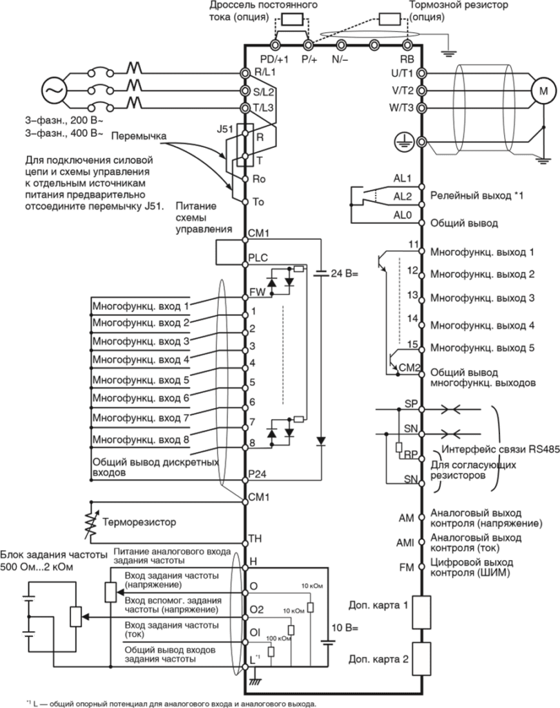
Клеммы силовых цепей.
| Обозначения клемм | Название клеммы | Описание |
| R/L1, S/L2, T/L3 | Клеммы ввода электропитания | Служат для подключения преобразователя частоты к источнику электропитания. |
| U/T1,V/T2, W/T3 | Клеммы питания электродвигателя | Служат для подключения к 3-фазному электродвигателю. |
| PD/+1, P/+ | Клеммы для внешнего дросселя постоянного тока | Отсоедините перемычку от клемм PD/+1 и P/+ и подключите дополнительный дроссель постоянного тока для повышения коэффициента мощности. |
| P/+, RB | Клеммы для подключения тормозного резистора | Служат для подключения дополнительного наружного тормозного резистора. (Клемма RB предусмотрена в преобразователях мощностью 22 кВт и ниже.) |
| P/+, N/- | Клеммы для подключения блока генераторного торможения | Служат для подключения дополнительных блоков генераторного торможения. |
| G |
Клемма заземления | Клемма для заземления корпуса преобразователя частоты. Подсоедините эту клемму к цепи заземления (типа D для класса 200 В, типа C для класса 400 В) |
Пункты меню режима дополнительной настройки
Для перехода между пунктами меню дополнительной настройки используйте клавиши ![]()
или
![]()
.
| Параметр | Содержание | Диапазон настройки | По умолчанию |
| Язык (Language) | Язык дисплея | 01: Английский 02: Немецкий 03: Французский 04: Испанский 05: Итальянский 06: Португальский 07: Японский 08: Китайский 09: Турецкий 10: Русский |
01 |
| Дата и время (Date and Time) | Установка даты и времени часов цифровой панели с ЖК-дисплеем | Дата: 2000/1/1…2099/12/31 Время: 00:00…23:59 Формат: 1, 2, 3 | 2009/01/01 00:00 1 |
| Запрет чтения (Read Lock) | Чтобы значения параметров, хранящиеся в памяти цифровой панели с ЖК-дисплеем, не могли быть изменены, выберите значение «Enable» (Включено) для параметра «Read lock». | 01: Включено (Enable) 02: Выключено (Disable) | 02 |
| Выбор модели ПЧ (INV Type Select) | Укажите серию используемого преобразователя частоты в данном параметре. В случае ввода неверного значения автоматически отобразится ошибка связи (COM ERROR). | 01: Модель 1 (MX2, LX, RX) (Type 1) 02: Модель 2 (JX) (Type 2) |
01 |
| Режим хранения для чтения/записи (R/W Storage Mode) | Данный параметр задает количество хранимых наборов параметров для режимов чтения (READ) и записи (WRITE). | 01: Один (Single) 02: Четыре (Quad) |
02 |
| Автоматическое выключение подсветки (Backlight Auto-Off) | Если в течение 1 минуты ни одна из клавиш цифровой панели не оказывается нажатой, задняя подсветка ЖК-дисплея гаснет. При нажатии любой клавиши подсветка вновь включается. Функция автоматического выключения задней подсветки не действует при возникновении аварийного отключения. | 01: Выключена (Off) 02: 1 минута (1 minute) |
01 |
| Backlight Flicker (Мигание подсветки) | Данный параметр позволяет разрешить или запретить свечение подсветки оранжевым цветом. | 01: Включено (Enable) 02: Выключено (Disable) |
01 |
| Сброс панели управления (Operator Reset) | Данная функция позволяет вернуть параметры цифровой панели с ЖК-дисплеем к принимаемым по умолчанию значениям. Сбрасываются значения следующих параметров: 1: Язык: Английский 2: Дата и время: 2009/01/01 ЧТВ 00:00 3: Формат времени: 01:ГГ/ММ/ДД 4: Запрет чтения: Выключено 5: Режим хранения для чтения/записи: Четыре 6: Автоматическое выключение задней подсветки: Выключена 7: Мигание подсветки: Включено После инициализации параметров необходимо установить правильные значения даты и времени. | 01: Да (YES) 02: Нет (NO) | 02 |
| Режим проверки (Check Mode) | В этом режиме можно проверить работоспособность светодиодных индикаторов, клавиш и т. п. | Проверка клавиш и светодиодов (Key&Led Check), проверка ЖКД (LCD Check), проверка ЭСППЗУ (EEPROM Check), проверка часов (RTC Check), проверка связи (Serial Loopback), режим отладки (Debug Mode), версия прошивки (Firmware Version). | — |
Список параметров для программирования
Режим настройки основных функций
| Номер параметра | Название функции | Диапазон настройки или контроля значений | Значение по умолчанию | Изменение во время работы | Ед. изм. |
| F001 | Установка/ контроль выходной частоты | 0,0/начальная частота…макс. частота двигателя 1/2/3 0,00…400,00 | 0,00 | Да | Гц |
| F002 | Время разгона 1 | 0,01…3600,00 | 10,00 | Да | с |
| d001 | Контроль выходной частоты | 0,00…400,00 | ⎯ | Да | Гц |
| d002 | Контроль выходного тока | 0,0…9999,0 | ⎯ | ⎯ | А |
| d003 | Контроль направления вращения | FWD: Прямое направление STOP: Стоп REV: Обратное направление | ⎯ | ⎯ | ⎯ |
| d004 | Контроль обратной связи ПИД-регулятора | 0,00…999000,00 (Отображается, если включена функция ПИДрегулирования) | ⎯ | ⎯ | ⎯ |
| d005 | Контроль многофункциональных входов | ⎯ | ⎯ | ⎯ | |
| d006 | Контроль многофункциональных выходов | ⎯ | ⎯ | ⎯ | |
| d007 | Контроль выходной частоты (после преобразования) | 0,00…39960,00 (Выходная частота x масштабный коэффициент (b086)) | ⎯ | Да | ⎯ |
| d008 | Контроль фактической частоты | -400,00…400,00 | ⎯ | ⎯ | Гц |
| d009 | Контроль задания момента | -200…200 | ⎯ | ⎯ | % |
| d010 | Контроль смещения момента | -200…200 | ⎯ | ⎯ | % |
| d012 | Контроль выходного момента | -200…200 | ⎯ | ⎯ | % |
| d013 | Контроль выходного напряжения | 0,0…600,0 | ⎯ | ⎯ | В |
Режим контроля
| Номер параметра | Название функции | Диапазон настройки или контроля значений | Значение по умолчанию | Изменение во время работы | Ед. изм. |
| d014 | Контроль входной мощности | 0,0…999,9 | ⎯ | ⎯ | Вт |
| d015 | Контроль потребленной энергии (кВт-ч) | 0,0…999999,9 | ⎯ | ⎯ | ⎯ |
| d016 | Контроль времени наработки в режиме «Ход» | 0…999999 | ⎯ | ⎯ | час |
| d017 | Контроль времени наработки при включенном питании | 0…999999 | ⎯ | ⎯ | час |
| d018 | Контроль температуры радиатора | -020, …200,0 | ⎯ | ⎯ | °C |
| d019 | Контроль температуры двигателя | -020, …200,0 | ⎯ | ⎯ | °C |
| d022 | Контроль продолжительности службы | ⎯ | ⎯ | ⎯ | |
| d023 | Контроль счетчика программы | 0…1024 | ⎯ | ⎯ | ⎯ |
| d024 | Контроль номера программы | 0…9999 | ⎯ | ⎯ | ⎯ |
| d025 | Контрольный параметр программирования привода (UM0) | -2147483647…2147483647 | ⎯ | ⎯ | ⎯ |
| d026 | Контрольный параметр программирования привода (UM1) | -2147483647…2147483647 | ⎯ | ⎯ | ⎯ |
| d027 | Контрольный параметр программирования привода (UM2) | -2147483647…2147483647 | ⎯ | ⎯ | ⎯ |
| d028 | Контроль счетчика импульсов | 0…2147483647 | ⎯ | ⎯ | ⎯ |
| d029 | Контроль задания положения | -1 073 741 823…1 073 741 823, если выбран режим HAPR -268 435 456…268 435 456, если выбран режим APR2 | ⎯ | ⎯ | ⎯ |
| d030 | Контроль текущего положения | -1 073 741 823…1 073 741 823, если выбран режим HAPR -268 435 456…268 435 456, если выбран режим APR2 | ⎯ | ⎯ | ⎯ |
| d031 | Часы | Установка даты и времени для цифровой панели управления с ЖК-дисплеем | ⎯ | ⎯ | ⎯ |
| d060 | Контроль режима работы ПЧ | 00…01 | ⎯ | ⎯ | ⎯ |
| d080 | Контроль количества аварийных отключений | 0…65535 | ⎯ | ⎯ | раз |
| d081 d082 d083 d084 d085 d086 | Контроль аварийных отключений 1 (последнее отключение) Контроль аварийных отключений 2 Контроль аварийных отключений 3 Контроль аварийных отключений 4 Контроль аварийных отключений 5 Контроль аварийных отключений 6 |
Код ошибки (условия при возникновении) →Выходная частота [Гц] → Выходной ток [A] →Напряжение шины пост. тока [В] →Общее время работы в режиме «Ход» [ч] →Общее время работы [ч] | ⎯ | ⎯ | ⎯ |
| d090 | Контроль состояния предупреждения | Код предупреждения 0…385 | ⎯ | ⎯ | ⎯ |
| d102 | Контроль напряжения постоянного тока | 0,0…999,9 | ⎯ | ⎯ | В |
| d103 | Контроль коэффициента нагрузки тормозного резистора | 0,0…100,0 | ⎯ | ⎯ | % |
| d104 | Контроль электронной тепловой защиты | 0,0…100,0 | ⎯ | ⎯ | % |
Параметры работы с двигателем
| F202 | * Время разгона 1 двигателя 2 | 0,01…3600,00 | 10,00 | Да | с |
| F302 | * Время разгона 1 двигателя 3 | 0,01…3600,00 | 10,00 | Да | с |
| F003 | Время торможения 1 | 0,01…3600,00 | 10,00 | Да | с |
| F203 | * Время торможения 1 двигателя 2 | 0,01…3600,00 | 10,00 | Да | с |
| F303 | * Время торможения 1 двигателя 3 | 0,01…3600,00 | 10,00 | Да | с |
| F004 | Выбор направления вращения для управления с панели | 00: Прямое (FWD) 01: Обратное (REV) | 00 | Нет | ⎯ |
| H002/H202 | Выбор параметров двигателя | 00: Стандартные параметры двигателя 01: Параметры автонастройки 02: Параметры автонастройки (включена оперативная автонастройка) | 00 | ⎯ |
| H003/H203 | Выбор мощности двигателя | 0,20…160,00 | Заводск. предуст. | кВт |
| H004/H204 | Выбор числа полюсов двигателя | 2/4/6/8/10 | 4 | Полюс |
| H030/H230 | Параметр R1 двигателя (значение для автонастройки) | 0,001…65,535 | Зависит от мощности двигателя. | ⎣ |
| H031/H231 | Параметр R2 двигателя (значение для автонастройки) | 0,001…65,535 | Зависит от мощности двигателя. | Ом |
| H032/H232 | Параметр L двигателя (значение для автонастройки) | 0,01…655,35 | Зависит от мощности двигателя. | мГн |
| H033/H233 | Параметр Io двигателя (значение для автонастройки) | 0,01…655,35 | Зависит от мощности двигателя. | А |
| H034/H234 | Параметр J двигателя (значение для автонастройки) | 0,001…9999,000 | Зависит от мощности двигателя. | кг*м2 |
| A003 | Основная частота | 30…макс. частота | 50 | Гц |
| A051 | Выбор торможения постоянным током | 00: Отключено (OFF) 01: Включено (ON) 02: Включено, когда частота < A052 (ON (FQ)) |
01 | ⎯ |
| A082 | Выбор напряжения для функции AVR | 200/215/220/230/240: значения для класса 200 В 380/400/415/440/460/480: значения для класса 400 В | 200/400 | ⎯ |
Расширенные функции
| Номер параметра | Название функции | Диапазон настройки или контроля значений | Значение по умолчанию | Изменение во время работы | Ед. изм. |
| A001 | Выбор способа ввода задания частоты | 00: Потенциометр FREQ на цифровой панели управления (VR) (Возможно только при использовании 3G3AX-OP01.) 01: Клемма 02: Цифровая панель управления (F001) 03: Интерфейс ModBus (RS485) 04: Дополнительная карта 1 05: Дополнительная карта 2 06: Импульсный вход задания частоты 07: Программирование привода (EzSQ) 10: Результат математической операции (Math) |
01 | Нет | — |
| A002 | Выбор способа подачи команды «Ход» | 01: Клемма 02: Цифровая панель управления (F001) 03: Интерфейс ModBus (RS485) 04: Дополнительная карта 1 05: Дополнительная карта 2 |
01 | Нет | ⎯ |
| A003 A203 A303 |
Основная частота * Основная частота двигателя 2 * Основная частота двигателя 3 |
30…максимальная частота [A004] 30…максимальная частота двигателя 2 [A204] 30…максимальная частота двигателя 3 [A304] |
50 50 50 |
Нет | Гц |
| A004 A204 A304 |
Максимальная частота *Максимальная частота двигателя 2 *Максимальная частота двигателя 3 | A003…400 A203…400 A303…400 |
50 50 50 |
Нет | Гц |
| A005 | Выбор входов O/OI | 00: Переключение между входом O и входом OI с помощью клеммы AT ([O]/ [OI]) 01: Переключение между входом O и входом O2 с помощью клеммы AT ([O]/ [O2]) 02: Переключение между входом O и потенциометром FREQ с помощью клеммы AT ([O]/VR) (Возможно только при использовании 3G3AX-OP01.) 03: Переключение между входом OI и потенциометром FREQ с помощью клеммы AT ([OI]/VR) (Возможно только при использовании 3G3AX-OP01.) 04: Переключение между входом O2 и потенциометром FREQ с помощью клеммы AT ([O2]/VR) (Возможно только при использовании 3G3AX-OP01.) | 00 | Нет | ⎯ |
| A006 | Выбор входа O2 | 00: Только вход O2 [O2] 01: Вспомогательное задание частоты O/ OI-P (не реверсируемое) 02: Вспомогательное задание частоты O/ OI-PM (реверсируемое) 03: Вход O2 отключен | 03 | Нет | ⎯ |
| A011 | Минимальная частота шкалы входа O | 0,00…400,00 | 0,00 | Нет | Гц |
| A012 | Максимальная частота шкалы входа O | 0,00…400,00 | 0,00 | Нет | Гц |
| A013 | Минимальный уровень сигнала шкалы входа O | 0…100 | 0 | Нет | % |
| A014 | Максимальный уровень сигнала шкалы входа O | 0…100 | 100 | Нет | % |
| A015 | Выбор начальной частоты для входа O | 00: Минимальная частота шкалы (значение в A011) 01: 0 Гц | 01 | Нет | ⎯ |
| A016 | Интервал опроса O, O2, OI | 1…30 31 (постоянная фильтра 500 мс, гистерезис ± 0,1 Гц) | 31 | Нет | ⎯ |
| A017 | Выбор программирования привода (EzSQ) | 0: Выключено 1: Запуск программы [PRG] 2: Всегда включено | 00 | Нет | ⎯ |
| A019 | Выбор ступенчатого переключения скорости | 00: Двоичный: выбор 16-ти ступеней с помощью 4 входов 01: Битовый: выбор 8-ми ступеней с помощью 7 входов | 00 | Нет | ⎯ |
| A020 | Задание ступенчатого переключения скорости 0 | 0,00…макс. частота [A004] | 6,00 | Да | Гц |
| A220 | *Задание ступенчатого переключения скорости 0 двигателя 2 | 0,00…макс. частота [A204] | 6,00 | Да | Гц |
| A320 | *Задание ступенчатого переключения скорости 0 двигателя 3 | 0,00…макс. частота [A304] | 6,00 | Да | Гц |
| A038 | Частота толчкового хода | 0,00/Начальная частота…9,99 | 6,00 | Да | Гц |
| A039 | Выбор способа остановки толчкового хода | 00: Выбег в толчковом режиме, отключено во время работы (FRS) 01: Торможение до остановки в толчковом режиме, отключено во время работы (DEC) 02: Торможение постоянным током в толчковом режиме, отключено во время работы (DB) 03: Выбег в толчковом режиме, включено во время работы (FRS (RUN)) 04: Торможение до остановки в толчковом режиме, включено во время работы (DEC (RUN)) 05: Торможение постоянным током в толчковом режиме, включено во время работы (DB (RUN)) | 04 | Нет | ⎯ |
| A051 | Выбор торможения постоянным током | 00: Отключено (OFF) 01: Включено (ON) 02: Включено, когда частота < A052 (ON (FQ)) | 01 | Нет | ⎯ |
| A052 | Частота начала торможения постоянным током | 0,00…400,00 | 0,50 | Нет | Гц |
| A053 | Время задержки торможения постоянным током | 0,0…5,0 | 0,0 | Нет | с |
| A054 | Сила торможения постоянным током | 0…100 (0,4…55 кВт) 0…80 (75…132 кВт) |
50 40 | Нет | % |
| A055 | Продолжительность торможения постоянным током | 0,0…60,0 | 0,5 | Нет | с |
| A056 | Выбор способа запуска торможения постоянным током | 00: Управление фронтом сигнала 01: Управление уровнем сигнала | 01 | Нет | ⎯ |
| A057 | Сила торможения постоянным током при запуске | 0…100 (0,4…55 кВт) 0…80 (75…132 кВт) | 0 | Нет | % |
| A058 | Продолжительность торможения постоянным током при запуске | 0,0…60,0 | 0,0 | Нет | с |
| A059 | Несущая частота при торможении постоянным током | 0,5…15,0 (0,4…55 кВт) 0,5…10,0 (75…132 кВт) |
5,0 3,0 | Нет | кГц |
| A061 A261 | Верхнее предельное значение частоты *Верхнее предельное значение частоты для двигателя 2 | 0,00/нижнее предельное значение частоты…макс. частота 0,00/нижнее предельное значение частоты для двигателя 2…макс. частота для двигателя 2 | 0,00 | Нет | Гц |
| A062 A262 | Нижнее предельное значение частоты *Нижнее предельное значение частоты для двигателя 2 | 0,00/начальная частота…верхнее предельное значение частоты 0,00/начальная частота…верхнее предельное значение частоты для двигателя 2 | 0,00 | Нет | Гц |
| A063 A064 A065 A066 A067 A068 | Частота пропуска 1 Ширина полосы частот пропуска 1 Частота пропуска 2 Ширина полосы частот пропуска 2 Частота пропуска 3 Ширина полосы частот пропуска 3 |
Центральная частота пропуска: 0,0…400,0 Ширина полосы частот (гистерезис) пропуска: 0,0…10,0 | 0,00 0,50 0,00 0,50 0,00 0,50 | Нет | Гц |
| A069 | Частота приостановки разгона | 0,00…400,00 | 0,00 | Нет | Гц |
| A070 | Время приостановки разгона | 0,0…60,0 | 0,0 | Нет | с |
| A071 | Выбор ПИДрегулирования | 00: Отключено (OFF) 01: Включено (ON (+)) 02: Включено, разрешен реверс выхода (ON (+/-)) | 00 | Нет | ⎯ |
| A072 | Коэффициент передачи П-звена ПИД-регулятора | 0,2…5,0 | 1,0 | Да | ⎯ |
| A073 | Коэффициент передачи И-звена ПИД-регулятора | 0,0…3600,0 | 1,0 | Да | с |
| A074 | Коэффициент передачи Д-звена ПИД-регулятора | 0,00…100,00 | 0,00 | Да | с |
| A075 | Масштабный коэффициент ПИДрегулятора | 0,01…99,99 | 1,00 | Нет | раз |
| A076 | Выбор входа сигнала обратной связи ПИДрегулятора | 00: Вход OI 01: Вход O 02: Интерфейс связи RS485 (Modbus) 03: Вход импульсной последовательности (Pulse) 10: Результат математической операции (Math) | 00 | Нет | ⎯ |
| A077 | Работа ПИДрегулятора в обратном направлении | 00: Рассогласование = уставка — значение сигнала обратной связи (OFF) 01: Рассогласование = значение сигнала обратной связи — уставка (ON) | 00 | Нет | ⎯ |
| A078 | Ограничение выхода ПИДрегулятора | 0,0…100,0 | 0,0 | Нет | % |
| A079 | Выбор входа управления с упреждением ПИДрегулятора | 00: Выключено 01: Вход O 02: Вход OI 03: Вход O2 | 00 | Нет | ⎯ |
| A081 | Выбор функции AVR | 00: Всегда включено 01: Всегда выключено 02: Выключено при торможении | 02 | Нет | ⎯ |
| A082 | Выбор напряжения для функции AVR | Класс 200 В: 200/215/220/230/240 Класс 400 В: 380/400/415/440/460/480 | 200/ 400 | Нет | В |
| A092 A292 A392 A093 A293 A393 | Время разгона 2 * Время разгона 2 двигателя 2 * Время разгона 2 двигателя 3 Время торможения 2 * Время торможения 2 двигателя 2 * Время торможения 2 двигателя 3 |
0,01…3600,00 | 10,00 10,00 10,00 10,00 10,00 10,00 | Да | с |
| A094 A294 | Выбор способа переключения на темп разгона/ торможения 2 *Выбор способа переключения на темп разгона/ торможения 2 для двигателя 2 | 00: С помощью многофункционального входа 09 (2CH) 01: По достижении заданной частоты (Preset FQ) 02: Только при переключении направления (прямое/обратное) (FWD-REV) | 00 00 | Нет | ⎯ |
| A095 A295 A096 A296 | Частота переключения на темп разгона 2 Частота переключения на темп разгона 2 для двигателя 2 Частота переключения на темп торможения 2 Частота переключения на темп торможения 2 для двигателя 2 |
0,00…400,00 | 0,00 0,00 0,00 0,00 | Нет | Гц |
| A097 A098 | Выбор профиля разгона Выбор профиля торможения | 00: Линейный профиль 01: S-профиль 02: U-профиль 03: Обращенный U-профиль 04: EL-S-профиль | 01 01 |
Нет | ⎯ |
| A141 A142 | Выбор входа A задания частоты Выбор входа B задания частоты | 00: Цифровая панель управления (F001) (Operator) 01: Потенциометр FREQ на цифровой панели управления (VR) (Возможно только при использовании 3G3AX-OP01.) 02: Вход O (O) 03: Вход OI (OI) 04: Интерфейс связи RS485 (Modbus) 05: Дополнительная карта 1 06: Дополнительная карта 2 07: Вход импульсной последовательности (Pulse) | 02 03 | Нет Нет | ⎯ |
| A143 | Выбор математической операции | 00: Сложение (A + B) (ADD) 01: Вычитание (A — B) (SUB) 02: Умножение (A x B) (MUL) | 00 | Нет | ⎯ |
| A145 | Поправка частоты | 0,00…99,99 100,0…400,0 | 0,00 | Нет | Гц |
| A146 | Выбор знака поправки частоты | 00: Добавление значения A145 к выходной частоте (ADD) 01: Вычитание значения A145 из выходной частоты (SUB) | 00 | Нет | ⎯ |
| A150 | Показатель кривизны EL-Sпрофиля в точке 1 во время разгона | 0…50 | 10 | Нет | % |
| A151 | Показатель кривизны EL-Sпрофиля в точке 2 во время разгона | 0…50 | 10 | Нет | % |
| A152 | Показатель кривизны EL-Sпрофиля в точке 1 во время торможения | 0…50 | 10 | Нет | % |
| A153 | Показатель кривизны EL-Sпрофиля в точке 2 во время торможения | 0…50 | 10 | Нет | % |
Список кодов ошибок Omron 3G3RX
| Название | Описание | Код ошибки | Возможные причины и способы устранения |
| Аварийное отключение из-за повышенного тока | Если вращению двигателя препятствуют внешние механические силы (заблокирован вал и т. п.), либо скорость вращения изменяется слишком быстро (в сторону увеличения или уменьшения), через преобразователь частоты протекает ток большой силы, что приводит к возникновению неисправности. Если ток становится больше установленного порогового уровня, выход ПЧ отключается и сигнализируется ошибка. Данная функция защиты распознает повышенный ток с помощью детектора переменного тока (CT). Схема защиты срабатывает и обесточивает выход ПЧ, если выходной ток приблизительно в 2,2 раза (220%) превосходит номинальный выходной ток ПЧ. | E01.0 E02.0 E03.0 E04.0 | Резко изменился уровень нагрузки. (Не допускать резкие перепады нагрузки.) Короткое замыкание в выходной цепи. (Проверить кабель питания двигателя.) Имеется замыкание на землю. (Проверить кабель питания двигателя и сам двигатель.) Слишком высокий темп торможения. (Увеличить время торможения.) Слишком высокий темп разгона. (Увеличить время разгона.) Заблокирован вал двигателя. (Проверить двигатель и кабель.) Слишком высокий «подъем» момента. (Уменьшить величину «подъема» момента.) Избыточное торможение постоянным током. (Уменьшить торможение постоянным током.) Неисправен детектор тока (CT). (Отремонтировать или заменить детектор тока.) |
| Аварийное отключение из-за перегрузки *1 | Контролируется выходной ток преобразователя частоты. Если функция электронной тепловой защиты обнаруживает перегрузку двигателя, выход ПЧ отключается и сигнализируется ошибка. Уровень срабатывания зависит от настройки параметров функции электронной тепловой защиты. | E05.0 | Слишком большая нагрузка. (Уменьшить коэффициент нагрузки.) Неправильно задан уровень срабатывания электронной тепловой защиты. (Задать подходящий уровень срабатывания тепловой защиты.) Примечание. Функция электронной тепловой защиты легко настраивается для работы при частоте вращения 5 Гц и ниже. При работе на высокоинерционную нагрузку функция защиты от перегрузки может срабатывать в начале разгона, так как высокий момент инерции нагрузки препятствует разгону. Если это происходит, следует увеличить величину «подъема» момента или принять другие меры для устранения этой ситуации. |
| Аварийное отключение из-за перегрузки тормозного резистора | Если коэффициент использования тормозного резистора превышает значение, заданное параметром b090, выход ПЧ отключается и сигнализируется ошибка. | E06.0 | Слишком высокий темп торможения. (Увеличить время торможения.) Высокая частота пусков/остановов. (Уменьшить частоту пусков/остановов.) Установлено слишком низкое значение коэффициента использования тормозного резистора (b090). (Задать подходящее значение.) Примечание. Также необходимо учитывать допустимую мощность рассеяния резистора. |
| Аварийное отключение из-за повышенного напряжения | Слишком высокое напряжение постоянного тока между полюсами P/+ и N/- может привести к повреждениям. Поэтому данная функция защиты отключает выход ПЧ и сигнализирует ошибку, если напряжение постоянного тока между полюсами P/+ и N/- становится больше установленного порогового уровня из-за возврата энергии двигателем в генераторном режиме или повышения входного напряжения во время работы. Отключение происходит, когда напряжение между полюсами P/+ и N/- достигает приблизительно 400 В= (для моделей класса 200 В) или 800 В= (для моделей класса 400 В). | E07.0 | Слишком высокий темп торможения. (Увеличить время торможения.) Имеется замыкание на землю. (Проверить кабель питания двигателя и сам двигатель.) Двигатель вращается/приводится в движение под действием внешней силы на стороне нагрузки. (Уменьшить энергию, генерируемую двигателем.) |
| Ошибка ЭСППЗУ *2 *3 |
Если из-за воздействия помех или нарушения температурного режима возникает ошибка в работе встроенной микросхемы ЭСППЗУ, выход преобразователя частоты отключается и сигнализируется ошибка. Примечание. В некоторых случаях вместо ошибки ЭСППЗУ может сигнализироваться ошибка центрального процессора. |
E08.0 | Поблизости есть источник электрических помех большой мощности. (Принять меры против электрических помех.) Снизилась эффективность охлаждения. (Проверить охлаждающий вентилятор и радиатор и очистить их при необходимости.) (Заменить охлаждающий вентилятор, если он неисправен.) |
| Аварийное отключение из-за пониженного напряжения | Если напряжение питающей электросети становится меньше установленного порогового уровня, выход преобразователя частоты отключается. Это вызвано тем, что при слишком низком напряжении на входе преобразователя частоты перестает работать схема управления. Отключение происходит, когда напряжение постоянного тока между полюсами P/+ и N/- снижается приблизительно до 175 В= (для моделей класса 200 В) или 345 В= (для моделей класса 400 В). | E09.0 | Понизилось входное напряжение. (Проверить напряжение питающей электросети.) Недостаточная мощность источника питания. (Проверить тех. характеристики источника питания.) Поврежден тиристор внутренней схемы плавного заряда. (Проверить тиристор.) |
| Ошибка CT | Если возникает ошибка в работе встроенного детектора тока (CT), выход преобразователя частоты отключается. Отключение происходит, если при поданном питании выходное напряжение CT составляет приблизительно 0,6 В или больше. | E10.0 | Неисправность в преобразователе частоты. (Выполнить ремонт или замену.) |
| Ошибка ЦПУ *1 | Если центральный процессор преобразователя частоты работает неправильно, выход преобразователя частоты отключается и сигнализируется ошибка. Примечание. В ряде случаев ошибка ЦПУ может сигнализироваться в результате считывания некорректных данных из ЭСППЗУ. | E11.0 | Поблизости есть источник электрических помех большой мощности. (Принять меры против помех.) Неисправность в преобразователе частоты. (Выполнить ремонт или замену.) |
| Внешнее отключение выхода | Если в работе внешнего оборудования или устройства возникает ошибка, на преобразователь частоты подается сигнал аварийного отключения. Выход ПЧ отключается. (Действует, только если выбрана функция внешнего отключения выхода.) | E12.0 | Включена функция внешнего отключения выхода, в работе внешнего оборудования произошла ошибка и на ПЧ был подан сигнал отключения. (Устранить ошибку во внешнем устройстве.) |
| Аварийное отключение из-за безнадзорного запуска | Если при включении питания на входе преобразователя частоты уже присутствует сигнал «Ход», выход ПЧ отключается. (Действует, только если выбрана функция защиты от безнадзорного пуска (USP)) | E13.0 | Включена функция защиты от безнадзорного пуска, питание ПЧ было включено, когда на входе ПЧ присутствовал сигнал «Ход». (Перед подачей питания выключить сигнал «Ход».) |
| Аварийное отключение из-за замыкания на землю *1 | Данная функция обеспечивает защиту преобразователя частоты при обнаружении замыкания на землю в цепи между ПЧ и электродвигателем в момент подачи питания на ПЧ. (Данная функция не работает при наличии остаточного напряжения на двигателе.) | E14.0 | Имеется замыкание на землю. (Проверить кабель питания двигателя и сам двигатель.) Ошибка или неисправность в самом ПЧ. (Отсоединить и проверить кабель питания двигателя.) Ошибка или неисправность силовой цепи. (Проверить силовую цепь. См. главу 6.) (Выполнить ремонт или замену.) |
| Аварийное отключение из-за повышенного входного напряжения | Если напряжение, поступающее на преобразователь частоты, дольше 100 секунд превышает указанное в технических характеристиках значение, в то время как ПЧ остановлен, выход ПЧ отключается. Отключение происходит, когда напряжение шины постоянного тока достигает приблизительно 390 В= (для моделей класса 200 В) или 780 В= (для моделей класса 400 В). | E15.0 | Когда ПЧ остановлен, на его вход поступает слишком высокое напряжение питания. (Уменьшить входное напряжение, устранить чрезмерные колебания напряжения. При необходимости, установить дроссель переменного тока в цепи ввода электропитания.) |
| Аварийное отключение из-за кратковременного прерывания электропитания | Если напряжение питания пропадает больше чем на 15 мс, выход преобразователя частоты отключается. Если подача электропитания прерывается надолго, это обычно воспринимается как полное отключение питания. Следует также иметь ввиду, что если выбран перезапуск двигателя, ПЧ возобновит вращение двигателя при восстановлении электроснабжения, если к тому времени все еще будет присутствовать команда «Ход». | E16.0 | Пониженное напряжение питающей электросети. (Восстановить нормальное электропитание.) Неисправен контакт АВЛК и/или ЭМК. (Заменить АВЛК и/или ЭМК.) |
| Ошибка температуры при уменьшении скорости вращения охлаждающего вентилятора | Данный код ошибки отображается, если при возникновении ошибки температуры обнаруживается снижение скорости вращения охлаждающего вентилятора. | E20.0 | Снизилась эффективность охлаждения. (Заменить охлаждающий вентилятор.) Засорилось пространство между пластинами радиатора. (Почистить радиатор.) |
| Ошибка температуры | Если температура в силовой цепи чересчур велика из-за высокой температуры окружающей среды, выход преобразователя частоты отключается. | E21.0 | ПЧ не установлен в вертикальном положении. (Проверить, как установлен ПЧ) Повышенная температура окружающей среды. (Уменьшить температуру окружающей среды.) |
| Ошибка связи с преобразовательной схемой | Если возникает ошибка при обмене данными между центральным процессором и преобразовательной схемой, выход ПЧ отключается. | E23.0 | Поблизости есть источник электрических помех большой мощности. (Принять меры противодействия электрическим помехам.) Отсоединился какой-либо кабель внутри ПЧ. (Проверить разъемы.) |
| Аварийное отключение из-за обрыва фазы | Неполнофазное питание может привести к повреждению преобразователя частоты. Если включена защита от пропадания входной фазы (b006=01), при пропадании фазы питающей сети выход ПЧ отключается. Отключение происходит, если фаза отсутствует приблизительно 1 с или дольше. | E24.0 | Обрыв одной из фаз входного напряжения. (Проверить входные цепи электропитания.) Неисправен контакт АВЛК и/или ЭМК. (Заменить АВЛК и/или ЭМК.) |
| Ошибка силовой цепи *1 | Если преобразовательная схема не может подтвердить включение/ выключение IGBT-модуля из-за отказа силового элемента, короткого замыкания в цепи нагрузки или неправильной работы вследствие воздействия излучаемых помех, выход преобразователя частоты отключается. | E25.0 | Поблизости есть источник электрических помех большой мощности. (Принять меры противодействия электрическим помехам.) Поврежден силовой элемент/IGBTмодуль. Короткое замыкание в выходной цепи. (Проверить IGBT-модуль.) Преобразователь частоты неисправен. (Выполнить ремонт или замену.) |
| Ошибка IGBTмодуля | В случае кратковременной перегрузки по току, ошибки температуры силового элемента или снижения управляющего напряжения силового элемента выход преобразователя частоты отключается с целью защиты силового элемента. (Автоматическое возобновление работы для этой ошибки не предусмотрено.) | E30.0 | Короткое замыкание в выходной цепи. (Проверить кабель питания двигателя.) Имеется замыкание на землю. (Проверить кабель питания двигателя и сам двигатель.) Поврежден силовой элемент. (Проверить IGBT-модуль.) Засорилось пространство между пластинами радиатора. (Почистить радиатор.) |
| Ошибка терморезистора | Преобразователь частоты следит за температурой двигателя по величине сопротивления терморезистора, подсоединенного к клемме TH. Если температура двигателя становится выше допустимого уровня, выход ПЧ отключается. | E35.0 | Двигатель слишком сильно нагревается. (Проверить температуру двигателя.) Поврежден терморезистор внутри двигателя. (Проверить терморезистор.) На сигнал терморезистора накладывается помеха. (Отделите цепи терморезистора от источника помех.) |
| Ошибка внешнего тормоза | Данная ошибка сигнализируется, когда включена функция управления внешним тормозом (b120 = 01) и после выдачи преобразователем частоты сигнала отпускания тормоза в течение заданного времени ожидания (b124) от тормоза не поступает сигнал подтверждения включения/выключения. | E36.0 | Тормоз не срабатывает на включение/ выключение. (Проверить внешний тормоз.) Заданное время ожидания b124 слишком мало. (Увеличить b124.) Обрыв в цепи сигнала подтверждения тормоза. (Проверить цепь сигнала подтверждения.) |
| Аварийное выключение *2 | Если переключатель SW1 на плате схемы управления находится в положении «ON», при поступлении сигнала на вход «EMR» (многофункц. вход 3) выход преобразователя частоты обесточивается (аппаратно) и сигнализируется ошибка. | E37.0 | Включена функция аварийного выключения, в работе внешнего оборудования произошла ошибка и на ПЧ был подан сигнал выключения. (Устранить ошибку во внешнем устройстве.) |
| Аварийное отключение из-за перегрузки в области малых скоростей | Если при очень низких оборотах двигателя (не более 0,2 Гц) электронная функция тепловой защиты преобразователя частоты обнаруживает перегрузку, выход ПЧ отключается. (В журнале ошибок, однако, может быть зарегистрировано более высокое значение частоты.) | E38.0 | Слишком большая нагрузка. (Уменьшить коэффициент нагрузки.) |
| Ошибка интерфейса связи Modbus | Данная ошибка сигнализируется, если в процессе обмена данными по интерфейсу Modbus-RTU по какойлибо причине (обрыв провода и т. п.) оказывается превышено время ожидания. (Действия ПЧ при ошибке связи определяются параметром C076.) | E41.0 | Неверное значение скорости связи. Превышена допустимая длина кабеля связи. (Проверить настройку параметров связи и кабель связи.) |
| Ошибка доп. карты 1 | Обнаружена ошибка карты, установленной в порт для доп. карты 1. | E60.0 … E69.0 | Дополнительная карта плохо зафиксирована. (Проверить, правильно ли выполнен монтаж карты.) |
| Ожидание из-за пониженного напряжения | Если входное напряжение опускается ниже допустимого уровня, преобразователь частоты отключает выход и ожидает с указанной индикацией. Данная ошибка также сигнализируется при кратковременном прерывании питания. | UV Wait | Пониженное напряжение питающей электросети. (Восстановить нормальное электропитание.) Неисправен контакт АВЛК и/или ЭМК. (Заменить АВЛК и/или ЭМК.) Напряжение между полюсами P/+ и N/- не соответствует норме. (Проверить напряжение между P/+ и N/-.) |
| Ошибка связи | Данная ошибка сигнализируется при нарушении обмена данными между преобразователем частоты и цифровой панелью управления. | COM ERROR | Неправильно подсоединен кабель панели управления. (Проверить правильность подсоединения кабеля.) Неправильно подсоединена цифровая панель управления. (Проверить подсоединение цифровой панели управления.) |
| Ожидание повторной попытки перезапуска | Данный код ошибки отображается во время ожидания повторной попытки запуска двигателя, когда действует функция возобновления работы после кратковременного прерывания питания или аварийного отключения выхода преобразователя частоты. | Restart Wait F-adj Wait |
В случае запуска с нулевой частоты. В случае запуска с подхватом скорости. |
| Отключение питания | Данный код ошибки сигнализируется при отключении электропитания преобразователя частоты. | Power OFF | ⎯ |
| Недопустимая команда «Ход» | Данная ошибка сигнализируется, если на преобразователь частоты поступает команда «Ход» в направлении, которое запрещено параметром b035. | RUN CMD. Disable | ⎯ |
Примечание:
Если вам необходим более широкий функционал частотного преобразователя, обратитесь к полной инструкции.
Скачать полное руководство по эксплуатации.
(Ocr-Read Summary of Contents of some pages of the Omron SYSDRIVE 3G3EV SERIES Document (Main Content), UPD: 24 May 2023)
-
8, 1-4 If an inspection or some other task is to be performed, always wait at least one minute from the time all indicators on the front panel go off. (Note that this warning is applicable whenever you perform any task after turning the main circuit off.) H Do Not Remove the Digital Operator When the Main Circuit is Still On. Always turn the main circuit off before removing the digital operator. Removing the digital operator with the main circuit ON may…
-
15, Omron SYSDRIVE 3G3EV SERIES 3-2 3-1 Installation 3-1-1 Outside/Mounting Dimensions Note All dimensions are in millimeters. H 3G3EV-A2001(-j) to 3G3EV-A2004(-j) (0.1 to 0.4 kW): Three-phase 200-VAC Input H 3G3EV-AB001(-j) to 3G3EV-AB002(-j) (0.1 to 0.2 kW): Single/Three-phase 200-VAC Input 4.5 dia. Note 1. For the 3G3EV-A2001(-j), 3G3EV-A2002(-j), and 3G3EV-AB001(-j), a U- shaped notch (4.5 mm wide) is provided instead of the upper mounting hole (4.5 mm in diameter). Note 2. Install the Inverter with two M4 bolts. Design …
-
56, 4-25 4-3 Test Run After wiring is complete, perform a test run of the Inverter as follows. First, start the motor through the Digital Operator without connecting the motor to the mechanical system. Next, connect the motor to the mechanical sys- tem and perform a test run. Finally, operate the controller to make sure that the sequence of operations is correct. This section only describes how to perform a test run using the Digital Operator. 4-3-1 Checking Wiring •Check…
-
47, Omron SYSDRIVE 3G3EV SERIES 4-16 n11 Frequency Reference 1 Setting range 0.0 to 400 (Hz) Factory setting 6.0 (Hz) n12 Frequency Reference 2 Setting range 0.0 to 400 (Hz) Factory setting 0.0 (Hz) •These constants are used to set reference frequency values. •The unit of setting is as follows: 0.0 to 99.9 (Hz): 0.1 (Hz) 100 to 400 (Hz): 1 (Hz) •The reference frequency value can be changed even during operation. To change the reference frequency value when the Inverter is being operated with the Digital Oper…
-
2, Thank you for choosing this SYSDRIVE 3G3EV-series product. Proper use and handling of the product will ensure proper product performance, will length product life, and may prevent possible accidents. Please read this manual thoroughly and handle and operate the product with care. NOTICE 1. This manual describes the functions of the product and relations with other products. You should assume that anything not described in this manual is not possible. 2. Although care has…
-
88, 7-11 Constant no. SettingSetting rangeDescriptionIndi- cators n21 Deceleration time 0.0 to 999 (seconds) [10.0] n24 Maximum frequency 50.0 to 400 (Hz) [60.0] n25 Maximum voltage 1 to 255 (V) (see note 1) [200] n26 Maximum voltage frequency (basic frequency) 1.6 to 400 (Hz) [60.0] n31 Electronic thermal reference current 0.0 to 120% of rated Inverter amperage Specify the rated motor amperage. n33 Stall p…
-
4, Table of Contents ii Chapter 5. Operation 5-1. . . . . . . . . . . . . . . . . . . . . . . . . . . . . . 5-1 Protective and Diagnostic Functions 5-2. . . . . . . . . . . . . . . . . . . . . . . . . . . . . . . 5-2 Troubleshooting 5-8. . . . . . . . . . . . . . . . . . . . . . . . . . . . . . . . . . . . . . . . . . . . . . . 5-2-1 Constants Fail to Set 5-8. . . . . . . . . . . . . . . . . . . . . . . . . . . . . . . . . . . . . . 5-2-2 Motor Fails to Operate 5-8. . . .…
-
12, 2-4 2-2 Component Names H Main Unit Main Circuit Terminals (Input) Power input terminals Braking resistor connection terminals Run indicator Alarm indicator Control circuit terminals (output) Ground terminal Main Circuit Terminals (Output) Motor output terminals Digital Operator Control circuit terminals (input) MA MB MC SF SR S1 SC FS FR FC L1 N/L2 L3 Note This diagram shows the Inverter with all terminal block covers removed. Overview Chapter …
-
70, 5-13 Under the wiring condition shown below, if the control output power supply is lower than 24 VDC or if it is set to OFF, current may flow in the direction shown by the arrows and may operate the Inverter input. In such a case, insert a diode in the A section shown below. A section SF SR S1 to S3 24 V 360 0.1µ GND SC 3.3 K 5-3 Maintenance and Inspection H Daily Inspection While the system is operating, check the following items: •Check the motor for noise. •Check for abnormal heati…
-
85, 7-8 H Braking Resistor (Duty Cycle 3% ED) Specifications Model 200-VAC class 0.1 kW/0.2 kW 400 Ω 3G3IV-PERF150WJ401 0.4 kW/0.75 kW 200 Ω 3G3IV-PERF150WJ201 1.5 kW 100 Ω 3G3IV-PERF150WJ101 400-VAC class 0.75 kW or less 750 Ω 3G3IV-PERF150WJ751 1.5 kW 400 Ω 3G3IV-PERF150WJ401 H Braking Resistor Unit (Duty Cycle 10% ED) Specifications Model 200-VAC class 0.4kW/0.75 kW 200 Ω, 70 W 3G3IV-PLKEB20P7 1.5 kW 100 Ω, 260 W 3G3IV-PLKEB21P5 400-VAC class 0.75 kW or less…
-
71, 5-14 H Regular Maintenance Check the items below during regular maintenance. Before starting inspection, always turn the power off, then wait at least one minute after all indicators on the front panel go off. Touching terminals immediately after turning the power off may cause an electrical shock. •Check the terminal block screws for looseness. •Check if electrically conductive dust or oil mist adheres to the terminal block. •Check the Inverter set s…
-
68, 5-11 5-2-6 Motor Burns •The dielectric strength of the motor is insufficient. Surge arises when the motor (inductive load) is connected to the output side of the Inverter. Normally, the maximum surge voltage is approximately three times the power voltage. Therefore, the dielectric strength of the motor to be used must be higher than the maximum surge voltage. It is recommended that motors specific…
-
66, Omron SYSDRIVE 3G3EV SERIES 5-9 •The reference frequency is too low. When the reference frequency is less than 1.5 Hz, the Inverter cannot operate. Change the reference frequency to 1.5 Hz or more. •The sequence input method is wrong. If the 3-wire sequence input mode is selected as an external terminal function instead of the actual 2-wire sequence input mode, the motor will not run, in which case change the constant or change…
-
54, 4-23 n61 Stop Key Selection Setting range 0, 1 Factory setting 0 •When inputting Inverter operation from the control terminals, the Stop Key on the Digi- tal Operator can be set to “enabled” or “disabled.” Value Description 0 Stop Key enabled 1 Stop Key disabled Note 1. When operating the Inverter from the Digital Operator, the Stop Key is always enabled irrespective of its setting. Note 2. This constant is available for models with a PROM number (software versi…
-
83, Omron SYSDRIVE 3G3EV SERIES 7-6 “SW1” is marked near the switch. Switch indicator V: Voltage input I: Amperage input DIP switch 5. Changing the DIP switch setting To use amperage input mode, set this switch to ON by sliding it to the right. (factory setting) 6. Reinstalling the Digital Operator After changing the switch setting, reinstall the Digital Operator by reversing the re- moval procedure. Make sure that the Digital Operator snaps in the connecto…
-
69, 5-12 S Install an input noise filter. Install an input noise filter (3G3IV-PHF) on the power input side of the Inverter. S Install an output noise filter. Install an output noise filter (3G3IV-PLF) on the output side of the Inverter. S Use metal box and piping. Metal can block off radio waves. Therefore, enclose the Inverter with a metal (steel) box to prevent radio waves from being emitted from the Inverter. 5-2-9 Ground Fault Interrupter is Actuated when Inverter is Started •Leakage current …
-
27, 3-14 D Never Connect Power Supply to Output Terminals CautionNever connect a power supply to output terminals U, V, and W. If voltage is applied to the output terminals, the internal mechanism of the Inverter will be damaged. D Never Short or Ground the Output Terminals CautionIf the output terminals are touched with bare hands or the output wires come into contact with the Inverter casing, an electric shock or grounding will occur. This is extremely hazardous. Also, be careful not to sho…
-
35, 4-4 H Function of Each Component D Display Sections Data display section Reference frequency values, output frequency values, output current values, constant settings, and error codes are displayed. Monitor item indicators When this indicator is lit, an output frequency value (Hz) is displayed in the data display section. When this indicator is lit, an output current value (effective current: A) is …