-
Contents
-
Table of Contents
-
Bookmarks
Quick Links
MINIMA MX2
Heating and Instantaneous Domestic Hot Water
Installation, Operating and Servicing Instructions
Manufactures N°
200906827037.31
200906828037.31
GB
IE
COMBINATION BOILER
Fanned Flue system
Model Type
MX2 24 FF NG
MX2 30 FF NG
Gas Council N°
47 — 980 — 28
47 — 980 — 29
c
Related Manuals for Chaffoteaux & Maury MINIMA MX2 24 FF NG
Summary of Contents for Chaffoteaux & Maury MINIMA MX2 24 FF NG
-
Page 1: Combination Boiler
MINIMA MX2 COMBINATION BOILER Heating and Instantaneous Domestic Hot Water Fanned Flue system Installation, Operating and Servicing Instructions Manufactures N° Model Type Gas Council N° 200906827037.31 MX2 24 FF NG 47 — 980 — 28 200906828037.31 MX2 30 FF NG 47 — 980 — 29…
-
Page 2: Guarantee
These instructions are suitable for the Minima MX2 boilers : Do not forget the Log Book! Chaffoteaux & Maury supports Benchmark, the heating industry code to ensure the correct installation, commissioning and servicing of domestic central heating systems. To The Householder Make sure you have a completed Log Book for your boiler.
-
Page 3: Table Of Contents
Table of Contents CUSTOMER CARE Guarantee Statutory Requirements Table of Contents USER’S INSTRUCTIONS CONTROL PANEL HOW TO USE MAINTENANCE FLUE GAS SAFETY GUARANTEE PRACTICAL INFORMATION INSTRUCTIONS FOR SETTING THE BUILT IN CLOCK INSTALLER’S INSTRUCTION DESCRIPTION DIMENSIONS HYDRAULIC DATA INSTALLATION REQUIREMENTS Reference Standards Codes of Practice Flue…
-
Page 4
SERVICING INSTRUCTIONS Replacement of Parts 22.1 To Gain General Access 22.1.1 Removing the front panel 22.1.2 Removing the side panels 22.1.3 Removing the control panel door 22.2 Access to the Combustion Chamber 22.2.1 Remove the combustion chamber front panel 22.2.2 Removing the burner manifold 22.2.3 Removing the electrodes… -
Page 5: Control Panel
USER’S INSTRUCTIONS Control Panel Fig. 1 Control panel (Fig. 1) Connecting bracket Taps shown in Open position (Fig. 2) 19. — Pressure gauge 31 : Central heating flow isolating valve 20. — On/off push button and power on indicator light 32 : Domestic hot water outlet 21.- DHW water temperature setting and start button 33 : Gas service tap…
-
Page 6
How to Use Starting up (Fig. 2) 1. Ensure that the mains gas supply isolating tap is open and that the appliance is supplied with power. 2. Ensure that there is sufficient pressure in the heating circuit: the pressure gauge needle should be at a minimum of 1.2 bar and a maximum of 1.7 bar when cold. -
Page 7: Maintenance
Maintenance Your boiler will work more reliably and efficiently if regularly serviced. We recommend an annual service check. The service history of the appliance will be marked on the Log Book. Flue Gas Safety The boiler is fitted with a safety system which authorises operation of the burner. If this device does not detect movement in the flue the boiler will shut down for safety reasons, and indicators 40, 60 and 80 flash 23 (Fig.
-
Page 8: Instructions For Setting The Built In Clock
Instruction For Setting the Built-in Clock (If Fitted) 1. General layout The mechanical clock covers a 24 hour period. Each tappet represents 15 minutes A (Fig. 4). An override switch is located on the clock B (Fig 4). 2. To set the time To set the time of day, grasp the outer edge of the dial and turn slowly clockwise until the correct time is lined up with the arrow C (Fig.
-
Page 9: Installer’s Instruction
INSTALLER’S INSTRUCTIONS Description 1.- Steel chassis complete with expansion vessel 2.- Sealed chamber 3.- Flue hood with fan 4.- Main heat exchanger 5.- Combustion chamber 6.- Multi-gas burner assembly comprising ignition and ionisation electrodes 7.- Gas valve assembly 8.- Pump with automatic air separator and automatic vent 9.- Overheat safety cut-out 10 — Return thermistor 11.- Flow thermistor…
-
Page 10: Dimensions
Dimensions All dimensions in mm Safety valve C/H Heating flow D.H.W. flow Gas supply 18,5 Cold water inlet Heating return With packaging : 24 kW : 32 kg 30 kW : 33 kg 172,5 121,5 J K L M N minimum space required 450mm 450 mini pour entretien 54 54 54 54…
-
Page 11: Installation Requirements
Installation Requirements Reference Standards Flue In the United Kingdom, the installation and initial start up of the boiler must be by a CORGI Registered installer in Detailed information on flue assembly can be found in Section accordance with the installation standards curently in effect, 12 “Connecting the Flue”.
-
Page 12: Gas Supply
Installation Requirements (continued) Fernox Manufacturing Ventilation Britannica Works The room in which the boiler is installed does not require specific Clavering ventilation. If it is installed in a cupboard or compartment Essex CB11 4QZ permanent ventilation is not required for cooling purposes. Tel: 01799 550811 Gas Supply The gas installation and soundness testing must be in…
-
Page 13: Connecting The Flue
Connecting the Flue The boiler must only be installed with a flue supplied by the boiler manufacturer. These kits are supplied separately to the appliance in order to respond to different installation solutions. For more information with regard to the inlet/outlet accessories consult the flue brochure and the following instructions.. The boiler is predisposed for the connection to a twin flow concentric gas intake and exhaust duct system.
-
Page 14
Connecting the Flue (continued) e.g. X = 508mm + 22mm = 530mm 860 — 530 = 330mm (Length to be cut from the plain end of the flue). Once cut to the required length, ensure that the flue is free from burrs and reassemble the flue. If fitting the flue from inside of the building attach the grey outer wall seal to the flue terminal and push through the flue through the hole, once the wall seal has passed through the hole, pull the flue back until the seal is flush with the wall. -
Page 15: Fitting The Coaxial Flue (Ø60/100 Vertical)
Connecting the Flue (continued) 12.3 Fitting the coaxial flue (Ø 60/100 Vertical) ONTENTS (60mm) ILICONE (60/100mm) ONICAL DAPTOR (80/125mm) ERTICAL CREWS The vertical flue kit is supplied with a specially designed weather proof terminal fitted, it can be used either with a flat roof or a pitched roof.
-
Page 16
Connecting the Flue (continued) must only be cut at the male end and it must be ensured that the distance between the inner and outer flue are kept (Fig. 13). When utilising the vertical flue system, action must be taken to ensure that the flue is supported adequately to prevent the weight being transferred to the appliance flue connection. -
Page 17: Fitting The 5″ Flue (Ø80/125)
Connecting the Flue (continued) 12.4 Fitting the 5” flue (Ø 80 / 125) Once the boiler has been positioned on the wall, it is necessary to insert the Ø80/125 adaptor into the boiler flue socket. Place the Ø 60mm insert (Fig. 20) into the boilers exhaust connection; Fit the grey seal over the boilers flue connection and ensuring all lip seals are fitted correctly push the adaptor onto the boilers flue connection, checking that the seal is fitted correctly over the adaptor;…
-
Page 18: Fitting The Twin Pipe (Ø80/80)
Connecting the Flue (continued) 12.5 Fitting the twin pipe (Ø80/80) Where it is not possible to terminate the flue within the distance permitted for coaxial flues, the twin flue pipe can be used by fitting a special adaptor to the flue connector and using the aperture for the air intake located on top of the combustion chamber.
-
Page 19
Connecting the Flue (continued) 60mm inner flue of the concentric terminal connects to the pipe bridge, this point must be adequately sealed with silicone sealant to avoid condense leakage at this point. : Vertical twin flue installations must have a trap on the exhaust. MTS supply a suitable condense trap Part No. 705774 and recommend that this be used in the event that the flue may not form condense. -
Page 20
Connecting the Flue (continued) Concentric outlet Restrictor 60/100 ø 88.5 Without restrictor Max. length 24 kW L min. = 0.3 m L min. = 1 m (Type 1, Type 2, Type 3) L max. = 1 m L max. = 4 m 30 kW L min. -
Page 21
Connecting the Flue (continued) RAWINGS ARE INDICATIVE OF FLUEING OPTIONS ONLY AIR INTAKE MUST NOT BE FITTED ABOVE THE EXHAUST AIR INTAKE EXHAUST AIR INTAKE Fig. 25… -
Page 22: Installing The Boiler
Installing the Boiler — place the template in the selected position on the wall — fit the hanging bracket — Install the gas and water pipes and the electrical connection to the locations shown on the fitting template — Drill the hole for the flue — unscrew the clamp locking bolt A, which secures the front panel (Fig.
-
Page 23: Electrical Connections
Electrical Connections MPORTANT Connection should be via a 3 amp fused double-pole isolating switch with contact separation of at least 3 mm on both poles. Alternatively, a fused 3 Amp. 3 pin plug and unswitched socket may be used, provided it is not used in a room containing a bath or shower.
-
Page 24
Electrical Connections (continued) — If a remote time clock is to be fitted, using a volt-free switching time clock, connect the switching wires from the time clock following points above (see also Diagram B Fig. 31). — If using an external time clock and room thermostat, these must be connected in series as above (see also Diagram C Fig. -
Page 25: Operating
Operating — Set the system pressure, close filling taps 36, 37 and PRESSURISING (Fig. 32) remove filling loop 38. Domestic Hot Water Circuit: — Check for leaks. — open the cold water tap 34 — Manually check pump is free to turn — open all hot water taps until water flows Gas circuit Central Heating Circuit:…
-
Page 26: Burner Gas Output Setting
Operating (continued) Célectic Tempo Débistat Sanitaire 1,5 sec Tempo Débistat Sanitaire 0 sec Domestic hot water flow switch time 1.5 sec. Domestic hot water flow switch time 0 sec. Fonctionnement Modulant On/Off operation Modulating operation Fonctionnement TOR Consigne chauffage à 40 °C Consigne chauffage variable de 35 à…
-
Page 27: Fitting The Casing
Fitting the Casing Fitting the casing Remove the protective film on the casing: — offer the casing up (Fig. 34) — engage hooks N on the casing in notches R (operation 1) — fit the top of the panel in place — close the panel mounting clamps (Fig.
-
Page 28: Completion
Completion For the Republic of Ireland it is necessary to complete a “Declaration of Conformity” to indicate compliance to I.S. 813. An example of this is given in the current edtion of I.S. 813. In addition to this it is necessary to complete the Log Book.
-
Page 29: Setting The Gas Pressures / Gas Type Conversion
Setting the Gas Pressures / Gas Type Conversion When adapting to a gas different from the one for which the boiler is equipped, you should replace the parts delivered with the conversion kit, and make the gas valve adjustments as described below: Fig.
-
Page 30: Particular Characteristics
Setting the Gas Pressures (continued) Maximum Burner Pressure (mbar) mbar G 20 G 30 G 31 24 kW FF 11.4 26.8 35.2 30 kW FF 26.5 35.9 Minimum Burner Pressure (mbar) mbar G 20 G 30 G 31 24 kW FF 30 kW FF Fig.
-
Page 31: Replacement Of Parts
SERVICING INSTRUCTIONS To ensure efficient safe operation, it is recommended that the boiler is serviced annually by a competent person. Before starting any servicing work, ensure both the gas and electrical supplies to the boiler are isolated and the boiler is cool.
-
Page 32: Access To The Combustion Chamber
22.2 Access to the Combustion Chamber 22.2.1 Removing the combustion chamber front panel 22.2.2 Removing the burner manifold 1. Carry out step 22.1.1; 1. Carry out step 22.1.1 and 22.2.1; 2. Unscrew five self tapping screws “D” to release 2. Unscrew the nut between manifold and gas pipe the combustion chamber front panel and lift clear (see Fig.
-
Page 33: Removing The Electrodes
22.2.3 Removing the electrodes 22.2.4 Removing the burner 1. Carry out steps 22.1.1 and 22.2.1; 1. Carry out steps 22.2.1, 22.2.1 and 22.2.2; 2. Unscrew the self tapping screws 2. Remove the two self tapping screws “F” securing the (see Fig. 49) 3.
-
Page 34: Removing The Main Heat Exchanger
22.2.5 Removing the main heat exchanger 1. Carry out step 22.1.1, 22.2.1 and 22.2.2; 2. Drain the boiler (only heating circuit); 3. Remove the 2 front clips “G” securing the heat exchanger (see Fig. 55); 4. Remove the NTC clips and overheat clip (see Fig. 56); 5.
-
Page 35: Removing The Air Pressure Switch
22.2.6 Removing the air pressure switch 22.2.7 Removing the fan Carry out step 22.1.1; Carry out step 22.1.1; (see Fig. 61) (see Fig. 64) 2. Disconnect the wire connectors 2. Disconnect the wire connectors (see (see 3. Disconnect the pressure pipes noting positions 3.
-
Page 36: Servicing And Removal Of The Gas Valve
22.3 Servicing and Removal of the Gas Valve 22.3.1 Removing the spark generator 22.3.2 Removing the gas valve 1. Carry out steps 22.1.1 and 22.1.3; ! Ensure the gas supply to boiler is turned off. MPORTANT 2. Disconnect ignition leads “I” by pulling left (see Fig. 68); 1.
-
Page 37: Access To The Water Circuit
22.4 Access to the Water Circuit Important! Before any component is removed, the boiler must be drained of all water. 22.4.1 Drain down DHW : close the DHW inlet tap and open a tap on the installation CH : Close the flow and return isolating valve and open the pressure relief valve.
-
Page 38: Removing The Pressure Relief Valve
22.4.4 Removing the pressure relief valve 22.4.6 Removing the pump 1. Carry out step 22.1.1 and 22.1.3; 1. Carry out step 22.1.1; 2. Remove the clip securing the valve (see Fig. 84) and 2. Lower the electrical box cover as in step 22.1.3 pull it toward you;…
-
Page 39: Removing The Overheat Thermostat
22.4.7 Removing the domestic expansion vessel 22.4.8 Removing the overheat thermostat 1. Remove the boiler from the wall 1. Remove the casing as in step 22.1.1 ; 2. Remove the two screws “T” (see Fig. 91); 2. Pull off the thermostat connections. Then remove 3.
-
Page 40: Access To The Control System
22.5 Access to the Control System 22.5.2 Removing the fuses 22.5.1 Removing the P.C.B.s 1. Carry out steps 22.5.1 ; 2. Remove the fuses “X” (see Fig. 99) 3. Reassemble in reverse order. 1. Isolate electricity; 2. Carry out step 22.1.1; 3.
-
Page 41: Incorrect Operation
Incorrect Operation If a fault occurs in the appliance, one or more LEDs (23 Fig. 1) flash according to the fault type listed in the table below. CODE FAULT INFORMATION 30 40 50 60 70 80 H H H H H G Overheating safety feature.
-
Page 42: Fault Finding
Fault Finding 24.1 Fault finding guide (flow-chart) It is possible to detect and correct defects by using the standard fault finding diagrams described in this chapter. HIS FAULT FINDING GUIDE IS NOT EXHAUSTIVE PRELIMARY CHECKS MAKE SURE THAT: 1 — There is sufficient water in the system 2 — The gas is turned on 3 — The electrical supply is…
-
Page 43
IS THE PUMP RUNNING? POWER TO THE PUMP? 1 — Check DHW flowswitch 2 — Check pump cable 3 — Check/replace P.C.B. 1 — Check that the pump is not stuck 2 — Release/replace pump IS THE FAN RUNNING? 1 — Check/replace POWER TO connection cable FAN ? -
Page 44
IS THE AIR PRESSURE SWITCH ACTIVATED? CHECK > ∆ P 1.2 mbar 1 — Check A.P. switch cable ∆P ON TEST 2 — Check/replace A.P. switch PRESSURE 3 — Check/replace P.C.B. INTAKE ≤ ∆ 1 — Check exhaust discharge P 1.2 mbar 2 — Check venturi &… -
Page 45: Electrical Diagrams
FAULTS POSSIBILE CAUSES Drawing D.H.W: THERE STILL — air in secondary heat exchanger When you turn on a tap A PROBLEM? — faulty D.H.W. flow switch burner switches off Drawing D.H.W: — faulty 3-way valve / gravity effect (see radiators heat up in summer mode page 41) Drawing D.H.W: — check temperature probes…
-
Page 46: Short Spare Parts List
Short Spare Parts List MX2 24 / MX2 30 SHORT LIST Manf. date Key N° Description G.C N° Manf. Pt. N° Type from FF FF 61010191 OVERHEAT THERMOSTAT 105°C 990686 THERMISTOR TEMP. SENSOR 990436 IGNITION ELECTRODE 61310933 FAN ASSY 24FF 61304721 FAN ASSY 30FF 61313340…
-
Page 47
NOTES… -
Page 48: Technical Data
Technical Data Model MX2 24 FF MX2 30 FF Appliance Category …………. 2H3+ 2H+3+ Heat output C/H ………….Pw 10 to 24 kW 12 to 30 kW Heat output DHW ……….Pw max 24 kW 30 kW DHW flow rates (∆T: 30 K) ……….11.4 I/min.
c
Heating and Instantaneous Domestic Hot Water
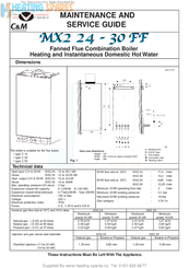
Dimensions
The boiler is suitable for the flue types:
• type C 12
• type C 32
• type C 52
Technical data
Heat input C/H & DHW
MX2 24 : 12 to 26,1 kW
Gross
MX2 30 : 12 to 32,25 kW
Heat output C/H & DHW MX2 24 : 10 to 24 kW
Gross
MX2 30 : 10 to 30kW
Max. operating pressure C/H circuit : 3 bar
Expansion vessel net capacity
Expansion vessel initial pressure
Electrical consumption
Voltage
Electrical protection index
Fuses
Nominal gas flow rate at 15°C and 1013 mbar
— Natural gas ( G 20) at 20 mbar
— Butane gas ( G 30) at 28 mbar
— Propane gas ( G 31) at 37 mbar
Injectors and gas valves seat diameter
— Manifold injectors (11 for 24 kW)
(14 for 30 kW)
Supplied By www.heating spares.co Tel. 0161 620 6677
MAINTENANCE AND
SERVICE GUIDE
Fanned Flue Combination Boiler
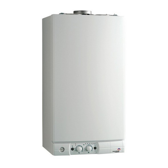
Outer case dimensions :
Fig. 1
: 6 l (24kW)
8 l (30 kW)
: 0.7 bar(24kW) 1bar (30kW)
: 150 w Max
: 230 v
: IP44
: 2 A , 1.25 A and 0.315 A
Maximum
power 24 kW
2.76 m
2.06 kg/h
2.02 kg/h
Natural gas
1.35 mm
These Instructions Must Be Left With The Appliance.
— Height : 720
— Width : 390 (minimum space required 400)
— Depth : 296
DHW flow rate at 30°C
DHW flow rate at 35°C
Minimum DHW operating flow rate
Minimum DHW working pressure
Maximum DHW working pressure
Gas category
MX2 24
Minimum
power 10 kW
3
/h
1.27 m
3
/h
0.94 kg/h
0.93 kg/h
MX2 24
Butane or Propane
0.80 mm
All dimensions in mm
I
Safety valve outlet
J Heating flow
K D.H.W. flow
L Gas supply
M Cold water inlet
N Heating return
MX2 24
:
11,4 l/min
MX2 30
:
14,3 l/min
MX2 24
:
9,85 l/min
MX2 30
:
12,25 l/min
:
2
:
0.1 bar
:
10 bar
:
II 2H 3+
MX2 30
Maximum
Minimum
power 30 kW
power 10 kW
3.41 m
3
/h
1.27 m
2.50 kg/h
0.94 kg/h
2.47 kg/h
0.93 kg/h
MX2 30
Natural gas
Butane or Propane
1,30 mm
0,80 mm
l/min
3
/h
(Ocr-Read Summary of Contents of some pages of the Chaffoteaux & Maury MINIMA MX2 24 FF NG Document (Main Content), UPD: 25 August 2023)
-
46, 46 MX2 24 / MX2 30 SHORT LIST 104 OVERHEAT THERMOSTAT 105°C 61010191 .. 108 THERMISTOR TEMP. SENSOR 990686 .. 110 IGNITION ELECTRODE 990436 .. 206 FAN ASSY 24FF 61310933 . FAN ASSY 30FF 61304721 . 216 AIR PRESSURE SWITCH 61313340 . AIR PRESSURE SWITCH 61313932 . 401 GAS VALVE 61312123 .. 444 IGNITER 61312612 .. 524 DHW…
-
23, 23 14 Electrical Connections Fig. 29 B C S T D J12 J1 J12 E J1 The 240 V and earth connection are made by using the lead provided at J1 (Fig. 30). I MPORTANT!! If the supply cable is damaged, it must be replaced. Room thermostat connection Before it leaves the factory, the boiler is set to operate without a room thermostat: a shunt S is placed on connector D. The room thermostat connection is made on this connector — Lower the electronic control unit by releasing the side locking pins P (Fig.…
-
33, 33 22.2.4 Removing the burner 1. Carry out steps 22.2.1, 22.2.1 and 22.2.2; 2. Remove the two self tapping screws “F” securing the burner (see Fig. 48); 3. Pull the burner out of the combustion chamber (see Fig. 53) ; 4. Remove the self tapping screws securing the electrodes (see Fig. 54) 5. Reassemble in reverse order; 6. Carry out combustion tests using the test point on the turret 1. Carry out steps 22.1.1 and 22.2.1; 2. Unscrew the…
-
17, 17 12 Connecting the Flue (continued) 12.4 Fitting the 5” flue (Ø 80 / 125) Once the boiler has been positioned on the wall, it is necessary to insert the Ø80/125 adaptor into the boiler flue socket. Place the Ø 60mm insert (Fig. 20) into the boilers exhaust connection; Fit the grey seal over the boilers flue connection and ensuring all lip seals are fitted correctly push the adaptor onto the boilers flue connection, checking that the seal is fit…
-
2, 2 These instructions are suitable for the Minima MX2 boilers : Do not forget the Log Book! Chaffoteaux & Maury supports Benchmark, the heating industry code to ensure the correct installation, commissioning and servicing of domestic central heating systems. To The Householder Make sure you have a completed Log Book for your boiler. This provides a record of the commissioning of your boiler. It contains important information about your particular installation that may be required by service …
-
24, Chaffoteaux & Maury MINIMA MX2 24 FF NG 24 14 Electrical Connections (continued) — If a remote time clock is to be fitted, using a volt-free switching time clock, connect the switching wires from the time clock following points above (see also Diagram B Fig. 31). — If using an external time clock and room thermostat, these must be connected in series as above (see also Diagram C Fig. 31 ). Live and Neutral connections to operate the clock motor must be t…
-
21, 21 EXHAUST AIR INTAKE AIR INTAKE AIR INTAKE MUST NOT BE FITTED ABOVE THE EXHAUST NOTE: DRAWINGS ARE INDICATIVE OF FLUEING OPTIONS ONLY. 12 Connecting the Flue (continued) TYPE 1 TYPE 5 TYPE 4 TYPE 3 TYPE 2 Fig. 25
… -
37, 37 22.4 Access to the Water Circuit Important! Before any component is removed, the boiler must be drained of all water. 22.4.3 Removing the float of the flow switch 1. Carry out step 22.1.1 and 22.1.3; 2. Disconnect the wire from the 3 way valve (see Fig. 75); 3. Remove the clip “P2” and the 3 way valve motor (see Fig. 76); 4. Unscrew the two screws “P3” and the 4 clips “Q1 * to Q4” (see Figs. …
-
22, 22 — place the template in the selected position on the wall — fit the hanging bracket — Install the gas and water pipes and the electrical connection to the locations shown on the fitting template — Drill the hole for the flue — unscrew the clamp locking bolt A, which secures the front panel (Fig. 26) — remove the front panel from the boiler (1 & 2 Fig. 26) — offer the water heater up to its bracket and allow it to drop into position while pressing on it (Fig. 27) — fit the connecto…
-
9, 9 8 Description INSTALLER’S INSTRUCTIONS Fig. 5 1 2 14 4 5 6 12 3 10 15 17 16 18 Fig. 6 7 8 9 11 1.- Steel chassis complete with expansion vessel 2.- Sealed chamber 3.- Flue hood with fan 4.- Main heat exchanger 5.- Combustion chamber 6.- Multi-gas burner assembly comprising ignition and ionisation electrodes 7.- Gas valve assembly 8.- Pump with automatic air separator and automatic vent 9.- Overheat safety cut-out …
-
12, 12 Ventilation The room in which the boiler is installed does not require specific ventilation. If it is installed in a cupboard or compartment permanent ventilation is not required for cooling purposes. Gas Supply The gas installation and soundness testing must be in accordance with the requirements of BS 6891.The boiler requires a 22 mm supply. Ensure that the pipe size is adequate for demand including other gas appliances on the same supply. Electrical Supp…
-
19, Chaffoteaux & Maury MINIMA MX2 24 FF NG 19 60mm inner flue of the concentric terminal connects to the pipe bridge, this point must be adequately sealed with silicone sealant to avoid condense leakage at this point. NOTE: Vertical twin flue installations must have a trap on the exhaust. MTS supply a suitable condense trap Part No. 705774 and recommend that this be used in the event that the flue may not form condense. When siting the twin flue pipe, the air intake and exhaust terminals must terminate on the s…
-
6, 6 2 How to Use NOTE: In some circumstances, it is possible that the pipes (and possibly a radiator) heat up slightly after hot water is drawn. To prevent this, simply close the central heating flow tap 31 (Fig. 2). Remember to re-open it at the start of the heating season, when you switch the heating back on by rotating button 22 (Fig. 1) or by turning the clock on. Starting up (Fig. 2) 1. Ensure that the mains gas …
-
7, 7 The boiler is fitted with a safety system which authorises operation of the burner. If this device does not detect movement in the flue the boiler will shut down for safety reasons, and indicators 40, 60 and 80 flash 23 (Fig. 1). IMPORTANT: this flue gas checking device must not be removed, or have untimely work carried out on it. If it needs to be replaced, only original parts may be used. 4 Flue Gas Safety 6 Practical Information The m…
-
5, 5 USER’S INSTRUCTIONS Control panel (Fig. 1) 19. — Pressure gauge 20. — On/off push button and power on indicator light 21.- DHW water temperature setting and start button 22.- Central heating temperature setting and start button 23.- Heating temperature indicator and diagnostic indicator 24.- Orange indicator — Burner ON 25.- Reset push button and red indicator lockout light Connecting bracket Taps shown in Open position (Fig. 2) 31 : Central heating flow isolating valve 32 : Domesti…
-
13, Chaffoteaux & Maury MINIMA MX2 24 FF NG 13 12 Connecting the Flue 12.1 Fitting the coaxial flue (Ø 60/100 Horizontal) The boiler must only be installed with a flue supplied by the boiler manufacturer. These kits are supplied separately to the appliance in order to respond to different installation solutions. For more information with regard to the inlet/outlet accessories consult the flue brochure and the following instructions.. The boiler is predisposed for the connection to a twin flow concentric gas i…
c
Heating and Instantaneous Domestic Hot Water
Dimensions
The boiler is suitable for the flue types:
• type C 12
• type C 32
• type C 52
Technical data
Heat input C/H & DHW
MX2 24 : 12 to 26,1 kW
Gross
MX2 30 : 12 to 32,25 kW
Heat output C/H & DHW MX2 24 : 10 to 24 kW
Gross
MX2 30 : 10 to 30kW
Max. operating pressure C/H circuit : 3 bar
Expansion vessel net capacity
Expansion vessel initial pressure
Electrical consumption
Voltage
Electrical protection index
Fuses
Nominal gas flow rate at 15°C and 1013 mbar
— Natural gas ( G 20) at 20 mbar
— Butane gas ( G 30) at 28 mbar
— Propane gas ( G 31) at 37 mbar
Injectors and gas valves seat diameter
— Manifold injectors (11 for 24 kW)
(14 for 30 kW)
Supplied By www.heating spares.co Tel. 0161 620 6677
MAINTENANCE AND
SERVICE GUIDE
Fanned Flue Combination Boiler
Outer case dimensions :
Fig. 1
: 6 l (24kW)
8 l (30 kW)
: 0.7 bar(24kW) 1bar (30kW)
: 150 w Max
: 230 v
: IP44
: 2 A , 1.25 A and 0.315 A
Maximum
power 24 kW
2.76 m
2.06 kg/h
2.02 kg/h
Natural gas
1.35 mm
These Instructions Must Be Left With The Appliance.
— Height : 720
— Width : 390 (minimum space required 400)
— Depth : 296
DHW flow rate at 30°C
DHW flow rate at 35°C
Minimum DHW operating flow rate
Minimum DHW working pressure
Maximum DHW working pressure
Gas category
MX2 24
Minimum
power 10 kW
3
/h
1.27 m
3
/h
0.94 kg/h
0.93 kg/h
MX2 24
Butane or Propane
0.80 mm
All dimensions in mm
I
Safety valve outlet
J Heating flow
K D.H.W. flow
L Gas supply
M Cold water inlet
N Heating return
MX2 24
:
11,4 l/min
MX2 30
:
14,3 l/min
MX2 24
:
9,85 l/min
MX2 30
:
12,25 l/min
:
2
:
0.1 bar
:
10 bar
:
II 2H 3+
MX2 30
Maximum
Minimum
power 30 kW
power 10 kW
3.41 m
3
/h
1.27 m
2.50 kg/h
0.94 kg/h
2.47 kg/h
0.93 kg/h
MX2 30
Natural gas
Butane or Propane
1,30 mm
0,80 mm
l/min
3
/h
-
Contents
-
Table of Contents
-
Bookmarks
Quick Links
COMBINATION BOILER
Heating only (system)
Heating + sanitary hot water together (system plus)
Open flue System
Installation and Operating Manual
MODE
MAN
AUTO
TEMP
C
GB
Related Manuals for Chaffoteaux & Maury Mira System CF
Summary of Contents for Chaffoteaux & Maury Mira System CF
-
Page 1
COMBINATION BOILER Heating only (system) Heating + sanitary hot water together (system plus) Open flue System Installation and Operating Manual MODE AUTO TEMP… -
Page 2: Table Of Contents
Contents Installer’s instruction Page 1 — description………………….2 — dimensions ………………….3 — water specifications ………………… 4 — installation requirements ………………5 — fitting the boiler………………..6 — electrical connections………………7 — starting up ………………….8 — fitting the casing ………………..9 — gas conversion ………………..
-
Page 3: Description
INSTALLER’S INSTRUCTION 1. Description 1.- sheet steel frame with expansion vessel 2.- overflow safety device 3.- draught diverter 4.- copper main heat exchanger 5.- combustion chamber 6.- multigas burner comprising: • a removable injector manifold • a ignition electrode • a flame detection electrode 7.- gas valve assembly comprising: •…
-
Page 4: Dimensions
2. Dimensions Measurements in mm Safety valve outlet ø Heating flow and tank Tank backflow (system plus) Gas inlet Cold water supply Heating backflow 175,3 Weight with packaging: 24 kW: 29 kg 172,5 121,5 J K L M N 450 min. for maintenance 450 mini pour entretien 54 54 54 54 ▲…
-
Page 5: Installation Requirements
4. Installation requirements 4.1 REGULATIONS 4.2 BOILER LOCATION PRIVATE HOMES — install the boiler near a duct for removing the products of combustion STATUTORY REQUIREMENTS FOR INSTALLATION AND MAINTENANCE — never install the boiler above hot-plates or ovens or in general over any equipment producing greasy vapours Installation and maintenance of the equipment must be car- which could make the boiler dirty and affect its operation…
-
Page 6: Fitting The Boiler
5. Fitting the boiler — place the paper installation jig in the selected position on the wall — fit the hanging bracket — bring the water pipes and the electrical connection to the locations shown on the fitting template — remove the 2 locking screws A which secure the front panel (fig. 7) — remove the front panel — offer the boiler up to its bracket and allow it to drop into position while pressing on it (fig.
-
Page 7: Electrical Connections
6. Electrical connections Regulations: — in accordance with the regulations, an all-pole iso- lating device with a contact opening gap of at least 3 mm must be installed in the boiler’s stationary power supply installation — the boiler must be connected to a fixed junction box using the cable supplied Location of connections: — the 230 V supply lead and room thermostat inputs…
-
Page 8: Starting Up
7. Operating PRESSURISATION (fig. 12) Heating circuit and tank: — open cold water tap 34 — check that the heating flow 31, heating backflow 35 and tank backflow 32 taps (compy system plus) are open — open filling tap 36 — close the tap again when the needle of pressure gauge 19 (fig.
-
Page 9: Factory Settings
7. Operating (continued) Célectic Tempo Débistat Sanitaire 1,5 sec Tempo Débistat Sanitaire 0 sec TIC 3 min. TIC 30 s. Post-circulation 30 s. Post-circulation 3 min. Post circulation 30 s Post circulation 3 mn Modulating Operation ON/OFF operation Fonctionnement Modulant Fonctionnement TOUT OU RIEN Heating setting to 40 °C Consigne chauffage à…
-
Page 10: Fitting The Casing
8. Fitting the casing Fitting the casing Remove the protective film on the casing: — offer up the casing (fig. 14) — engage hooks N in notches R operation 1 — fit the top of the panel in place — screw in the 2 front panel securing screws A Note: it is essential to refit both locking bolts A Fig.14 Fig.15…
-
Page 11: Gas Conversion
9. Gas conversion When changing to a gas different from the one for which the boiler is equipped, you should replace the parts supplied with the conversion kit and adjust the gas valve in accordance with the method described below. Adjusting the nominal output •…
-
Page 12: Fault Codes
10. Fault codes — Information If the equipment has an operating fault, one or more LEDs (23) flash according to the type of fault listed in the table below. LED Coding FAULT DESCRIPTION INFORMATION 30 40 50 60 70 80 H H H H H H H H H H G G Locked — overheating.
-
Page 13: Points To Note
11. Particular characteristics By-pass valve assembly direction…
-
Page 14: Controls
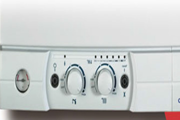
INSTRUCTIONS FOR THE USER 12. Controls (system plus) Fig.20 Control panel (fig. 20) Taps and valves (fig. 21) 19. — heating circuit pressure gauge 31. Central heating flow isolating valve and tank 32. Tank backflow (system plus) 20. — ON/OFF push button and ON indicator light 33: Gas tap 21.- domestic hot water function ON and hot water 34: Cold water supply tap…
-
Page 15: Operation
13. Operation Starting up 1. check that the appliance’s general gas shut-off tap is open and that the boiler is supplied with power. 2. check that there is sufficient pressure in the heating circuit: pressure gauge needle at least 1.2 bar with 1.7 bar at max. cold 3.
-
Page 16: Maintenance
14. Maintenance Current legislation requires a mandatory annual service of your water heater. Once a year, have it checked by a qualified professional. Annual service contract formats may be suggested to you by service providers for all boiler servicing. Contact your gas fitter or our commercial services.
-
Page 17: Warranty
16. Warranty Your boiler is under warranty. The warranty certificate specifies the warranty conditions: check that the detachable section of this certificate has been returned to Chaffoteaux & Maury. A qualified professional must have installed, adjusted and commissioned your installation for the warranty to be valid. This assures you that the fitter complied with the installation manual and that regulatory and safety conditions have been met.
-
Page 18: Technical Specification
18. Technical specifications Model 24 kW CF 7,5 — 24 KW Heating power 24 kW Variable tank pre-heating power Pn max Class I — type B11BS (natural draught/chimney/overflow safety device) Category II 2E+3+ Fresh air flow rate required for combustion 48 m Combustion products mass flow rate 20 g/s…
-
Page 19: Operating Faults
19. Operating faults Fault Cause Solution Control gas, water and electrical The boiler doesn’t start No gas, no water or no electricity supply, fuses… Air in the gas pipe Follow procedure in chapter 8 Room thermostat switched off Set up the room thermostat Wait for a few minutes Press on reset button 25 (fig.20) the red led turn off and the boiler attempts to re-…
-
Page 20
MTS sa Le Carré Pleyel 5 rue Pleyel 93521 SAINT DENIS Cedex Tél. 01 55 84 94 94 Fax 01 55 84 96 10 www.chaffoteaux-maury.fr…
Chaffoteaux & Maury Britony System 60 User`S Manual | Manualzz

Котел настенный газовый двухконтурный Chaffoteaux and Maury серии Mira System FF (модель с закрытой камерой сгорания. Инструкция по монтажу и.
Chaffoteaux & Maury Mira System CF Manuals

Инструкция на Котел настенный газовый Chaffoteaux and Maury серии Mira System СF бренда Chaffoteaux — скачать бесплатно в формате pdf.
Котел Chaffoteaux Maury Mx2 24 Cf Инструкция

as your local Chaffoteaux Service Centre. Chaffoteaux & Maury are continuously improving their products and therefore reserve the right to change.
Котел Chaffoteaux Maury Mx2 24 Cf Инструкция
Free Boiler Manuals, Free Gas Manuals, Gas Documents, Templates,
Chaffoteaux MIRA 24 CF Инструкция, Форум, Отзывы

Manuals and User Guides for Chaffoteaux & Maury Calydra comfort 100. We have 1 Chaffoteaux & Maury Calydra comfort 100 manual available for free PDF.
Chaffoteaux & Maury Britony System 60 Instruction Manual | Manualzz

Накопительный газовый водонагреватель CHAFFOTEAUX & MAURY AG 195 CF — купить сегодня c доставкой и гарантией по выгодной цене.
Chaffoteaux MIRA COMFORT 24 FF Инструкция, Форум, Отзывы

Вы можете скачать с сайта Diplodocs инструкцию CHAFFOTEAUX & MAURY в формате PDF. Введите модель изделия CHAFFOTEAUX & MAURY.
Chaffoteaux Maury Инструкция

Сюда складываем схемы подключения , ссылки на инструкции, фотографии узлов , плат , описываем характерные неисправности и.
Котел Chaffoteaux Maury Mx2 24 Cf Инструкция
для первой установки. — для замены котлов Chaffoteaux & Maury. — для замены котлов других марок. — набор для монтажа (в случае подвода труб сзади.
Blog Archives — Tofreg

Продукция CHAFFOTEAUX & MAURY (ШАФУТО И МАУРИ) в интернет- магазине TEPLO.com. Описание, характеристики и цены. Купить со СКИДКОЙ 5.
Chaffoteaux & Maury Britony Combi SE Manuals | ManualsLib

Котел настенный газовый двухконтурный Chaffoteaux and Maury серии Mira System FF (модель с закрытой камерой сгорания. Инструкция по монтажу и.
Chaffoteaux & Maury Centora Green 30 Nat Manuals

Котлы настенные газовые котлы chaffoteaux et maury talia system инструкция. описание samsung digimax cyber630. Договорились, — сказал Беккер и.
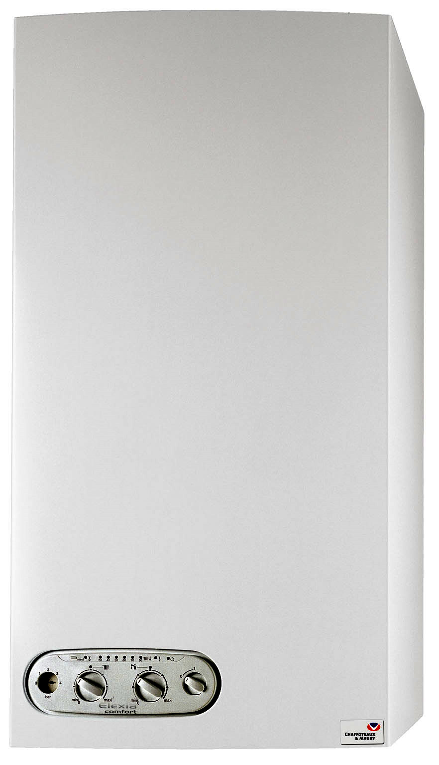
Инструкция По Elexia

View and Download Chaffoteaux & Maury MX2 24 FF maintenance & serice manual online. MX2 24 FF Boiler pdf manual download. Also for: Mx2 30.
Chaffoteaux Maury Elexia Comfort Инструкция

Инструкция по монтажу и техническому обслуживанию. Руководство по эксплуатации. по монтажу. Merlony_Z379_2005.jpg, Chaffoteaux & Maury
Chaffoteaux & Maury CORVEC 28 BF Manuals
Первый монтаж. — Замена старого котла Chaffoteaux. — Замена котлов других марок. Подробности смотрите в каталоге фурнитуры CHAUFFOTEAUX.
Chaffoteaux Et Maury Manual

Chaffoteaux MIRA COMFORT 24 FF Газовый Котёл инструкция, поддержка, форум, описание, мануал, руководство, Инструкция по эксплуатации.
Chaffoteaux Maury Elexia Comfort Инструкция
Listed below are all the manuals for Chaffoteaux. Just click on the model or the Gas council number and the manual will download at the bottom of the page.
All Categories — Managerbrod
Инструкция на Котел настенный газовый Chaffoteaux and Maury серии Mira System FF бренда Chaffoteaux — скачать бесплатно в формате pdf.
Chaffoteaux ALIXIA 24 FF CF Инструкция, Форум, Отзывы

Заказ ☎ (096)640-50-01, ☎ (066) 682-04-76, ☎ (063)437-67-61 (044) 338-58- 89 Тепло Без Газа — 10 лет опыта.
All Categories — Campingbook
Инструкция на Котел настенный газовый Chaffoteaux and Maury серии Mira Comfort СF бренда Chaffoteaux — скачать бесплатно в формате pdf.
Наш сайт использует файлы cookie и похожие технологии, чтобы гарантировать максимальное удобство пользователям, предоставляя персонализированную информацию, запоминая предпочтения в области маркетинга и продукции, а также помогая получить правильную информацию.
Внимание! Сайт работает в тестовом режиме. Возможны ошибки при работе с сайтом и некорректно установленные цены.
Открыть сайдбар
г. Оренбург, ул. Карагандинская, д. 32 (отправка курьерскими службами по России)
- Часы работы (по Москве):
пн-пт: 07:00 — 16:00
сб-вс: 07:00 — 16:00
- 8 (800) 3500-763
- Наш адрес —
- г. Оренбург, ул. Карагандинская, д. 32 (отправка курьерскими службами по России) —
×
Написать в Telegram:
Если у вас на компьютере установлено приложение Telegram Desktop, то просто перейдите по этой ссылке и напишите нам.
Альтернативный способ:
Установите и откройте Telegram, найдите контакт
и напишите нам.
×
Написать в WhatsApp:
Если у вас на компьютере установлено приложение WhatsApp, то просто перейдите по этой ссылке и напишите нам.
Альтернативный способ:
Внесите этот номер в адресную книгу своего телефона:
+79226257000
Установите и откройте WhatsApp, найдите созданный контакт и напишите нам.
×
Написать в Viber:
Если у вас на компьютере установлено приложение Viber, то просто перейдите по этой ссылке и напишите нам.
Альтернативный способ:
Внесите этот номер в адресную книгу своего телефона:
+
Установите и откройте Viber, найдите созданный контакт и напишите нам.
×
Написать в Skype:
Если у вас на компьютере установлен Telegram Skype, то просто перейдите по этой ссылке и напишите нам.
Альтернативный способ:
Установите и откройте Skype, найдите контакт
и напишите нам.
×
- Часы работы (по Москве):
пн-пт: 07:00 — 16:00
сб-вс: 07:00 — 16:00
- Часы работы (по Москве):
пн-пт: 07:00 — 16:00
сб-вс: 07:00 — 16:00
CHAFFOTEAUX & MAURY MX2 / MIRA
Товар добавлен в корзину
