-
Contents
-
Table of Contents
-
Troubleshooting
-
Bookmarks
Quick Links
dummyhead
dummyhead
HOW TO USE THIS MANUAL
A Few Words About Safety
HOW TO USE THIS MANUAL
Service Information
The service and repair information contained in this manual is intended for use by qualified, professional technicians. Attempting
service or repairs without the proper training, tools, and equipment could cause injury to you or others. It could also damage the
vehicle or create an unsafe condition.
This manual describes the proper methods and procedures for performing service, maintenance and repairs. Some procedures
require the use of specially designed tools and dedicated equipment. Any person who intends to use a replacement part, service
procedure or a tool that is not recommended by Honda, must determine the risks to their personal safety and the safe operation of
the vehicle.
If you need to replace a part, use Honda Genuine parts with the correct part number or an equivalent part. We strongly recommend
that you do not use replacement parts of inferior quality.
For Your Customer’s Safety
Proper service and maintenance are essential to the customer’s safety and the reliability of the vehicle. Any error or oversight while
servicing a vehicle can result in faulty operation, damage to the vehicle, or injury to others.
Improper service or repairs can create an unsafe
condition that can cause your customer or others to
be seriously hurt or killed.
Follow the procedures and precautions in this
manual and other service materials carefully.
For Your Safety
Because this manual is intended for the professional service technician, we do not provide warnings about many basic shop safety
practices (e.g., Hot parts–wear gloves). If you have not received shop safety training or do not feel confident about your knowledge
of safe servicing practice, we recommended that you do not attempt to perform the procedures described in this manual.
Some of the most important general service safety precautions are given below. However, we cannot warn you of every
conceivable hazard that can arise in performing service and repair procedures. Only you can decide whether or not you should
perform a given task.
Failure to properly follow instructions and
precautions can cause you to be seriously hurt or
killed.
Follow the procedures and precautions in this
manual carefully.
Important Safety Precautions
Make sure you have a clear understanding of all basic shop safety practices and that you are wearing appropriate clothing and
using safety equipment. When performing any service task, be especially careful of the following:
• Read all of the instructions before you begin, and make sure you have the tools, the replacement or repair parts, and the skills
required to perform the tasks safely and completely.
• Protect your eyes by using proper safety glasses, goggles or face shields any time you hammer, drill, grind, pry or work around
pressurized air or liquids, and springs or other stored-energy components. If there is any doubt, put on eye protection.
• Use other protective wear when necessary, for example gloves or safety shoes. Handling hot or sharp parts can cause severe
burns or cuts. Before you grab something that looks like it can hurt you, stop and put on gloves.
• Protect yourself and others whenever you have the vehicle up in the air. Any time you lift the vehicle, either with a hoist or a jack,
make sure that it is always securely supported. Use jack stands.
Make sure the engine is off before you begin any servicing procedures, unless the instruction tells you to do otherwise. This will
help eliminate several potential hazards:
• Carbon monoxide poisoning from engine exhaust. Be sure there is adequate ventilation whenever you run the engine.
• Burns from hot parts or coolant. Let the engine and exhaust system cool before working in those areas.
• Injury from moving parts. If the instruction tells you to run the engine, be sure your hands, fingers and clothing are out of the way.
Gasoline vapors and hydrogen gases from batteries are explosive. To reduce the possibility of a fire or explosion, be careful when
working around gasoline or batteries.
• Use only a nonflammable solvent, not gasoline, to clean parts.
• Never drain or store gasoline in an open container.
• Keep all cigarettes, sparks and flames away from the battery and all fuel-related parts.
0-1
Chapters
Troubleshooting
Summary of Contents for Honda CBR650F
- Manuals
- Brands
- Honda Manuals
- Motorcycle
- CBR650F 2014
- Owner’s manual
-
Contents
-
Table of Contents
-
Troubleshooting
-
Bookmarks
Quick Links
Contents
P. 2
P. 16
P. 39
P. 82
P. 102
P. 124
P. 128
Related Manuals for Honda CBR650F 2014
Summary of Contents for Honda CBR650F 2014
-
Page 1: Table Of Contents
Contents Motorcycle Safety P. 2 Operation Guide P. 16 Maintenance P. 39 Troubleshooting P. 82 Information P. 102 Specifications P. 124 Index P. 128…
-
Page 2
Honda dealer knows your motorcycle Honda motorcycle. Your selection of a best. If you have the required mechanical Honda makes you part of a worldwide family “know-how” and tools, you can purchase an of satisfied customers who appreciate official Honda Service Manual to help you Honda’s reputation for building quality into… -
Page 3
A Few Words About Safety Your safety, and the safety of others, is very DANGER important. Operating this motorcycle safely is You WILL be KILLED or SERIOUSLY an important responsibility. HURT if you don’t follow instructions. To help you make informed decisions about safety, we have provided operating WARNING procedures and other information on safety… -
Page 4: Motorcycle Safety
Motorcycle Safety This section contains important information for safe riding of your motorcycle. Please read this section carefully. Safety Guidelines ………P. 3 Safety Labels ……….P. 7 Safety Precautions ……..P. 9 Riding Precautions ……..P. 10 Accessories & Modifications……P. 14 Loading …………P. 15…
-
Page 5: Safety Guidelines
Safety Guidelines Safety Guidelines Before Riding Make sure that you are physically fit, mentally Follow these guidelines to enhance your safety: focused and free of alcohol and drugs. Check ● Perform all routine and regular inspections that you and your passenger are both wearing specified in this manual.
-
Page 6
Safety Guidelines We recommend that all riders take a certified Make Yourself Easy to See course approved by the Motorcycle Safety Make yourself more visible, especially at night, Foundation (MSF). New riders should start with by wearing bright reflective clothing, the basic course, and even experienced riders positioning yourself so other drivers can see will find the advanced course beneficial. -
Page 7
Safety Guidelines check the tightness of critical nuts and bolts, Keep Your Honda in Safe Condition and check the handlebars, control levers, It’s important to keep your motorcycle properly brakes, and wheels. Ride slowly and cautiously. maintained and in safe riding condition. -
Page 8
Safety Guidelines Carbon Monoxide Hazard WARNING Exhaust contains poisonous carbon monoxide, Carbon monoxide gas is toxic. a colorless, odorless gas. Breathing carbon Breathing it can cause monoxide can cause loss of consciousness and unconsciousness and even kill you. may lead to death. Avoid any areas or activities that If you run the engine in confined or even partly enclosed area, the air you breathe could contain… -
Page 9: Safety Labels
Safety Labels Safety Labels hazards that could cause serious injury. Read these labels carefully and don’t remove them. Safety and information labels on your If a label comes off or becomes hard to read, motorcycle provide important safety contact your dealer for a replacement. information and may warn you of potential continued…
-
Page 10
Safety Labels… -
Page 11: Safety Precautions
Safety Precautions Safety Precautions ● Face shield with unobstructed field of vision or other approved eye protection. ● Ride cautiously and keep your hands on the handlebars and feet on the footpegs. Look for a DOT (Department of ● Keep passenger’s hands on the seat strap or Transportation) certification label on any helmet your waist, passenger’s feet on the footpegs you buy.
-
Page 12: Riding Precautions
Riding Precautions ❙ Riding Precautions Boots or Riding Shoes Sturdy boots with non-slip soles and ankle protection Break-in Period ❙ During the first 300 miles (500 km) of running, Jacket and Pants follow these guidelines to ensure your Protective, highly visible, long-sleeved jacket motorcycle’s future reliability and performance.
-
Page 13
Riding Precautions ❙ ● Exercise caution on low traction surfaces. Anti-lock Brake System (ABS) CBR650FA only The tires slip more easily on such surfaces and braking distances are longer. This model is equipped with an Anti-lock Brake ● Avoid continuous braking. System (ABS) designed to help prevent the Repeated braking, such as when brakes from locking up during hard braking. -
Page 14
Riding Precautions ❙ Engine Braking Parking Engine braking helps slow your motorcycle ● Park on a firm, level paved surface. down when you release the throttle. For further ● If you must park on a slight incline or loose slowing action, downshift to a lower gear. Use surface, park so that the motorcycle cannot engine braking with intermittent use of the move or fall over. -
Page 15
Riding Precautions ❙ Parking with the Side Stand Refueling and Fuel Guidelines 1. Stop the engine. Follow these guidelines to protect the engine 2. Push the side stand down. and catalytic converter: 3. Slowly lean the motorcycle to the left until its ●… -
Page 16: Accessories & Modifications
Honda or make modifications to your motorcycle from its Follow all instructions in this owner’s original design.
-
Page 17: Loading
Loading Loading WARNING ● Carrying extra weight affects your Overloading or improper loading can motorcycle’s handling, braking and stability. cause a crash and you can be seriously Always ride at a safe speed for the load you hurt or killed. are carrying.
-
Page 18: Operation Guide
Parts Location Rear brake fluid reservoir (P67) Fuel fill cap (P36) Front brake fluid reservoir (P67) (P79) Front brake lever Throttle grip (P78) Engine oil fill cap/dipstick (P61) Coolant reserve tank (P65) Rear brake pedal Brakelight switch (P69)
-
Page 19
(P76) Clutch lever (P60) Battery (P101) Main fuse Fuse boxes (P100) (P37) Tool kit (P38) Document bag (P59) Seat Rear suspension spring preload (P80) adjuster (P71) Drive chain (P35) Shift lever (P70) Side stand Engine oil drain bolt (P63) (P63) Engine oil filter… -
Page 20
Instruments Tachometer red zone (excessive engine rpm range) button button Display Check When the ignition switch is turned on, the display will temporarily show all the modes and digital segments. If any part of these displays does not come on when it should, have your dealer check for problems. -
Page 21
Tachometer NOTICE Do not operate the engine in the tachometer red zone. Excessive engine speed can adversely affect engine life. Speedometer Fuel gauge Remaining fuel when only 1st (E) segment starts flashing: approximately 1.1 US gal (4.0 liters) At the same time, the display switches to the reserve fuel consumption. -
Page 22
Instruments (Continued) Odometer [TOTAL] & Tripmeter [TRIP A/B] & Fuel mileage meter & Fuel consumption meter button selects the odometer, tripmeter A, tripmeter B, current fuel mileage, average fuel mileage and fuel consumption (P22) To reset the tripmeter: Odometer Tripmeter A Tripmeter B Current fuel Average fuel Fuel… -
Page 23
The average fuel mileage and fuel consumption will be based on tripmeter A. • Current fuel mileage: Current instant fuel mileage. If your speed is less than 5 mph (7 km/h), “ ” is displayed. When “ ” is displayed at speeds above 5 mph (7 km/h), go to your dealer for service. •… -
Page 24
Instruments (Continued) ❙ To reset the tripmeter, average fuel Then, the display returns to the last selected indication. mileage and fuel consumption To reset tripmeter A, average fuel mileage, and fuel consumption together, press and hold button with tripmeter A, average fuel mileage, and fuel consumption To reset tripmeter B, press and hold displayed. -
Page 25
Reserve fuel consumption display • Flashes from “0.0” gal (US gal) or L (liter). When the 1st (E) segment of the fuel gauge When the amount of consumed fuel is more than 0.55 US gal (2.1 liters) the starts flashing, the odometer & tripmeter & display blinks faster. -
Page 26
Instruments (Continued) Display Setting Ordinary display Press the button to cycle through the setting choices. • Clock setting Clock setting • Backlight brightness adjustment • Activating/deactivating of tripmeter A, Backlight brightness adjustment average fuel mileage and fuel consumption automatic reset mode Activating/deactivating of tripmeter A, •… -
Page 27
In addition, to move the ordinary display at Press button. The minute digits start flashing. display setting. • The button is not pressed for about 30 seconds. • Turn the ignition switch off and then on. Press button until the desired minute is displayed. -
Page 28
Instruments (Continued) 2 Backlight brightness adjustment: Press button. The backlight is set, and then the display moves to activating/ You can adjust the brightness to one of three deactivating of tripmeter A, average fuel levels. mileage and fuel consumption automatic Press button. -
Page 29
3 Activating/deactivating of tripmeter A, To end the selection, press button. average fuel mileage and fuel The activation/deactivation of automatic consumption automatic reset mode: reset mode is set, and then the display You can activate or deactivate the automatic moves to the changing of the speed and reset mode by refuelling after 1st (E) segment mileage unit. -
Page 30
Instruments (Continued) 4 Changing of speed and mileage unit: When selecting the “mph” and “mile.” To end the selection, press button. Press button to select either “mph” and “mile” or “km/h” and “km.” The established setting can also be set by turning the ignition switch to OFF. -
Page 31
5 Changing of fuel mileage meter unit: To end the selection, press button. Press button to select “L/100km” or The established setting can also be set by “km/L.” turning the ignition switch to OFF. The control is automatically switched from the setting mode to the ordinary display if the button is not pressed for about 30 seconds. -
Page 32
Indicators PGM-FI (Programmed Fuel Injection) malfunction indicator lamp (MIL) High beam indicator Comes on briefly when the ignition switch is turned on with the engine stop switch in the (Run) position. Comes on when the ignition switch is turned on with the engine stop switch in the (Off) position. -
Page 33
Left turn signal indicator right turn signal indicator ABS (Anti-lock Brake System) indicator CBR650FA only Comes on when the ignition switch is turned on. Goes off when your speed reaches approximately 6 mph (10 km/h). Neutral indicator (P86) If it comes on while riding:… -
Page 34
Switches Engine stop switch Should normally remain in the (Run) position. In an emergency, switch to (Off) position (the starter motor will not operate) to stop the engine. Start button Hazard switch Switchable when the ignition switch is Horn button on. -
Page 35
Ignition Switch Turns electrical system Switches the electrical system on/off, locks the on for starting/riding. steering. Key can be removed when in the OFF or LOCK Turns engine off. position. LOCK Locks steering. ❙ Steering Lock Locking Lock the steering when parking to help Turn the handlebars all the way to the left. -
Page 36
Starting the Engine Start your engine using the following Make sure the engine stop switch is in the (Run) position. procedure, regardless of whether the engine is cold or warm. Turn the ignition switch to the ON position. Shift the transmission to Neutral ( indicator comes on). -
Page 37
Shifting Gears ❙ Your motorcycle transmission has 6 forward Recommended Shift Points gears in a one-down, five-up shift pattern. Shifting Up From 1st to 2nd 12 mph (20 km/h) From 2nd to 3rd 19 mph (30 km/h) From 3rd to 4th 25 mph (40 km/h) From 4th to 5th 31 mph (50 km/h) -
Page 38
Refueling Opening the Fuel Fill Cap Ignition key Level plate Open the lock cover, insert the ignition key, and turn it clockwise to open the cap. Lock cover Closing the Fuel Fill Cap After refueling, push the fuel fill cap closed until it locks. -
Page 39
Storage Equipment The helmet holder, the helmet set wire (in the tool kit) and the tool kit are located under the seat. There is also space to store a U-shaped lock. The U-shaped lock is held in place above the U-shaped lock rear fender. -
Page 40
Storage Equipment (Continued) The document bag and luggage tie-down hooks are located on the underside of the seat. Luggage tie-down hooks Luggage tie-down hooks Document bag Underside of the seat Never use the tie-down hooks to tow or lift the motorcycle. ❙… -
Page 41: Maintenance
Please read “Importance of Maintenance” and “Maintenance Fundamentals” carefully before attempting any maintenance. Refer to “Specifications” for service data. An optional larger tool kit may be available. Check with your Honda dealer’s parts department. Importance of Maintenance ….. P. 40 Throttle …………P.
-
Page 42: Importance Of Maintenance
Importance of Maintenance For information about the exhaust emission and Importance of Maintenance noise emission requirements of the U.S. Keeping your motorcycle well-maintained is Environmental Protection Agency (EPA), the absolutely essential to your safety and to California Air Resources Board (CARB), and protect your investment, obtain maximum Environment Canada (EC).
-
Page 43
Importance of Maintenance Follow these guidelines when performing Maintenance Safety maintenance. Always read the maintenance instructions ● Stop the engine and remove the key. before you begin each task, and make sure that ● Park your motorcycle on a firm, level surface you have the tools, parts, and skills required. -
Page 44: Maintenance Schedule
If you sell the motorcycle, these receipts should be transferred with the Maintenance work should be performed in motorcycle to the new owner. accordance with Honda’s standards and specifications by properly trained and equipped technicians. Your dealer meets all of these requirements. Keep an accurate record of maintenance to help ensure that your motorcycle is properly maintained.
-
Page 45
: Intermediate. We recommend service by your dealer, unless you Maintenance Legend have the necessary tools and are mechanically skilled. : Inspect (clean, adjust, lubricate, or replace, if necessary) Procedures are provided in an official Honda Service Manual : Lubricate 119). : Replace : Technical. -
Page 46
Maintenance Schedule Frequency Items × 1,000 mi Refer to page × 1,000 km 12.8 19.2 25.6 32.0 38.4 Drive Chain Every 500 mi (800 km) Brake Fluid Brake Pads Wear Brake System Brakelight Switch Headlight Aim Clutch System Side Stand Suspension Nuts, Bolts, Fasteners –… -
Page 47: Maintenance Fundamentals
Maintenance Fundamentals ● Suspension spring preload is adjusted to Pre-ride Inspection suit load. P. 80 To ensure safety, it is your responsibility to perform a pre-ride inspection and make sure Check the following items after you get on that any problem you find is corrected. A pre- your motorcycle: ride inspection is a must, not only for safety, ●…
-
Page 48
Maintenance Fundamentals Also, check the odometer reading against the Periodic Checks Maintenance Schedule and perform all You should also perform other periodic maintenance that is due. P. 43 maintenance checks at least once a month regardless of how often you ride, or more often if you ride frequently. -
Page 49
Maintenance Fundamentals Replacing Parts Color label Always use Honda Genuine Parts or their equivalents to ensure reliability and safety. When ordering colored components, specify the model name, color, and code mentioned on the color label. The color label is attached to the frame under the seat. -
Page 50
Maintenance Fundamentals ● Electrolyte splashes into your mouth: Battery Rinse mouth thoroughly with water, and Your motorcycle has a maintenance-free type do not swallow. battery. You do not have to check the battery WARNING electrolyte level or add distilled water. Clean the battery terminals if they become dirty or The battery gives off explosive corroded. -
Page 51
30 days using a charger designed specifically for 3. If the terminals are heavily corroded, clean your Honda, which can be purchased from your the terminals with a wire brush or sandpaper. dealer. Read the information that came with Wear safety glasses. -
Page 52
Jump starting using an automobile battery can damage your motorcycle’s electrical system and is not recommended. Bump starting is also not recommended. NOTICE Installing non-Honda electrical accessories can overload the electrical system, discharging the battery and possibly NOTICE damaging the system. -
Page 53
P. 125 higher oils, excluding oils marked as “Energy Conserving” or “Resource Conserving” on the If you use non-Honda engine oil, check the label circular API service symbol. to make sure that the oil satisfies all of the following standards: ●… -
Page 54
Wipe up spills immediately and wash thoroughly. pins or missing O-rings, or kinks, have the chain inspected by your dealer. Recommended brake fluid: Honda DOT 4 Brake Fluid or equivalent WARNING Clean filler cap before removing. Use only DOT 4 fluid from a sealed… -
Page 55
After cleaning, wipe dry and lubricate with a lubricant designed specifically for use on O-ring Normal Worn Damaged chains. (GOOD) (REPLACE) (REPLACE) Recommended lubricant: Pro Honda HP Chain Lube or equivalent NOTICE Use of a new chain with worn sprockets will cause rapid chain wear. continued… -
Page 56
Recommended Coolant degrading its performance. Pro Honda HP coolant is a pre-mixed solution of If the filter becomes dirty, replace it with a new antifreeze and distilled water. one. -
Page 57
Maintenance Fundamentals ❙ Inspecting for Damage Tires (Inspecting/Replacing) Inspect the tires for ❙ Checking the Air Pressure cuts, slits, or cracks Visually inspect your tires and use an air that exposes fabric or pressure gauge to measure the air pressure at cords, or nails or least once a month or any time you think the other foreign objects… -
Page 58
Maintenance Fundamentals ❙ Inspecting Tread Depth WARNING Inspect the tread wear indicators. If they become visible, replace the tires immediately. Riding on tires that are excessively For your safety, you should replace the tires worn or improperly inflated can cause when the minimum tread depth is reached. -
Page 59
Maintenance Fundamentals ● Have the wheel balanced with Honda WARNING Genuine balance weights or equivalent after the tire is installed. Installing improper tires on your ● Do not install a tube inside a tubeless tire on motorcycle can adversely affect this motorcycle. -
Page 60
Maintenance Fundamentals ❙ Tire Identification Number (TIN) Tire Service Life The tire identification number (TIN) is a group of The service life of your tires is dependent on numbers and letters located on the sidewall of many factors, including, but not limited to, the tire. -
Page 61: Removing & Installing Body Components
Removing & Installing Body Components ❙ Seat Removal 1. Insert the ignition key into the seat lock, and turn and hold the key clockwise to Front prong Seat unlock the seat. Rear prongs 2. Pull the rear of the seat back and up. ❙…
-
Page 62: Battery
Removing & Installing Body Components Battery Battery 1. Remove the seat. P. 59 2. Unhook the rubber strap from front side. 3. Disconnect the negative terminal from Positive the battery. terminal 4. Disconnect the positive terminal from Rubber the battery. Negative strap 5.
-
Page 63: Engine Oil
Engine Oil Checking the Engine Oil 1. If the engine is cold, idle the engine for 3 to 5 minutes. 2. Turn the ignition switch off, stop the Upper engine and wait for 2 to 3 minutes. level 3. Remove the oil fill cap/dipstick and wipe it clean.
-
Page 64
Engine Oil Adding Engine Oil Adding Engine Oil NOTICE Overfilling with oil or operating with insufficient oil can If the engine oil is below or near the lower cause damage to your engine. Do not mix different brands level mark, add the recommended engine oil. and grades of oil. -
Page 65
Changing Engine Oil & Filter Changing the oil and filter requires special tools. We recommend that you have your motorcycle serviced by your dealer. Use a new Honda Genuine oil filter or equivalent specified for your model. NOTICE Drain bolt… -
Page 66
Engine Oil Changing Engine Oil & Filter 9. Install a new sealing washer onto the drain bolt. Tighten the drain bolt. Torque: 22 lbf·ft (30 N·m, 3.1 kgf·m). 10. Fill the crankcase with the recommended oil ( 51) and install the oil fill cap/ dipstick. -
Page 67: Coolant
Coolant Checking the Coolant 1. Place your motorcycle on a firm, level surface. 2. Hold your motorcycle in an upright position. UPPER level 3. Check that the coolant level is between LOWER level the UPPER and LOWER level marks on the reserve tank cover.
-
Page 68
Coolant Changing Coolant 1. Remove the reserve tank cap and add Reserve tank cap fluid while monitoring the coolant level. Do not overfill above the UPPER level mark. Make sure no foreign objects enter the reserve tank opening. 2. Securely reinstall the cap. UPPER level WARNING Removing the radiator cap while the… -
Page 69: Brakes
Brakes Checking Brake Fluid If the brake fluid level in either reservoir is below the LOWER level mark or the brake 1. Place your motorcycle in an upright lever and pedal freeplay becomes excessive, position on a firm, level surface. inspect the brake pads for wear.
-
Page 70
Brakes Inspecting the Brake Pads Inspecting the Brake Pads Front Inspect the brake pads from below the brake caliper. Check the condition of the brake pad groove Always inspect both left and right wear indicators. calipers. The pads need to be replaced if a brake pad Rear Inspect the brake pads from the is worn to the indicator. -
Page 71
Brakes Adjusting the Brakelight Switch Adjusting the Brakelight Switch Check the operation of the brakelight switch. Hold the brakelight switch and turn the adjusting nut in the direction A if the switch operates too late, or turn the nut in the direction B if the switch operates too soon. -
Page 72: Side Stand
Side Stand 4. Start the engine, pull the clutch lever in, and shift the transmission into gear. 5. Lower the side stand all the way. The engine should stop as you lower the side stand. If the engine doesn’t stop, have your motorcycle inspected by your dealer.
-
Page 73: Drive Chain
Drive Chain Inspecting the Drive Chain Slack Check the drive chain slack at several points along the chain. If the slack is not constant at all points, some links may be kinked and binding. Have the chain inspected by your dealer. 1.
-
Page 74
Drive Chain Adjusting the Drive Chain Slack Adjusting the Drive Chain Slack Lock nut Adjusting plate Adjusting the chain requires special tools. Have the drive chain slack adjusted by your dealer. CBR650FA only Scale When adjusting the drive chain slack, be graduations careful not to damage the wheel speed sensor and pulser ring. -
Page 75
Drive Chain Adjusting the Drive Chain Slack 5. Turn both adjusting bolts an equal 7. Tighten the rear axle nut. number of turns until the correct drive Torque: 72 lbf·ft (98 N·m, 10.0 kgf·m). chain slack is obtained. Turn the adjusting 8. -
Page 76
Drive Chain Adjusting the Drive Chain Slack ❙ Checking the Drive Chain Wear Check the chain wear label when adjusting the drive chain. If the index mark on the adjusting plate enters the red zone on the label after the chain has been adjusted to the proper slack, the chain is excessively worn and must be replaced. -
Page 77: Clutch
Clutch Checking the Clutch Check the clutch cable for kinks or signs of wear. If necessary have it replaced by your ❙ Checking the Clutch Lever Freeplay dealer. Lubricate the clutch cable with a Check the clutch lever freeplay. commercially available cable lubricant to Freeplay at the clutch lever: prevent premature wear and corrosion.
-
Page 78
Clutch Adjusting the Clutch Lever Freeplay Adjusting the Clutch Lever Freeplay Upper lock nut ❙ – Upper Adjustment Attempt adjustment with the upper clutch cable adjuster first. 1. Loosen the upper lock nut. 2. Turn the upper clutch cable adjuster until the freeplay is 3/8 to 13/16 in (10 to 20 Upper clutch cable adjuster mm). -
Page 79
Clutch Adjusting the Clutch Lever Freeplay 1. Loosen the upper lock nut and turn the Lower adjusting nut Lower lock nut upper clutch cable adjuster all the way in (to provide maximum freeplay). Tighten the upper lock nut. 2. Loosen the lower lock nut. 3. -
Page 80: Throttle
Throttle Checking the Throttle With the engine off, check that the throttle rotates smoothly from fully closed to fully open in all steering positions and throttle freeplay is correct. If the throttle does not move smoothly, close automatically, or if the cable is damaged, have the motorcycle inspected by your dealer.
-
Page 81: Other Adjustments
Other Adjustments Adjusting the Brake Lever After adjustment, check that the lever operates correctly before riding. You can adjust the distance between the tip NOTICE of the brake lever and handle grip. Do not turn the adjuster beyond its natural limit. ❙…
-
Page 82: Rear Suspension
Other Adjustments Adjusting the Rear Suspension Adjusting the Rear Suspension Pin spanner 1 2 3 4 5 Adjusting the suspension requires pin spanner and extension bar. We recommend that you have your motorcycle serviced by your dealer. ❙ Spring Preload You can adjust the spring preload by the Adjuster adjuster to suit the load or the road surface.
-
Page 83: Headlight Aim
Other Adjustments Adjusting the Headlight Aim Adjusting the Headlight Aim You can adjust vertical aim of the headlight for proper alignment. Turn the pinion using a Phillips screwdriver in or out as necessary. Obey local laws and regulations. Lower Raise Pinion…
-
Page 84: Troubleshooting
Troubleshooting Engine Will Not Start ………P. 83 Other Warning Indications ……. P. 87 Overheating (High coolant temperature Fuel Gauge Failure Indications….P. 87 indicator is on)……….P. 84 Tire Puncture……….P. 88 Warning Indicators on or Flashing….P. 85 Electrical Trouble ……..P. 96 Low Oil Pressure Indicator……P.
-
Page 85: Engine Will Not Start
Engine Will Not Start ❙ ❙ Starter Motor Operates But Engine Starter Motor Does Not Operate Does Not Start Check the following items: ● Check the following items: Make sure engine stop switch is in the ● Check the correct engine starting (Run) position.
-
Page 86: Overheating (High Coolant Temperature Indicator Is On)
Overheating (High coolant temperature indicator is on) The engine is overheating when the 2. Check that the radiator fan is operating, following occurs: and then turn the ignition switch to the ● High coolant temperature indicator comes OFF position. If the fan is not operating: ●…
-
Page 87: Warning Indicators On Or Flashing
Warning Indicators on or Flashing Low Oil Pressure Indicator If the engine oil level goes down rapidly, your motorcycle may have a leak or another If the low oil pressure indicator comes on, serious problem. Have your motorcycle pull safely to the side of the road and stop inspected by your dealer.
-
Page 88: Abs (Anti-Lock Brake System) Indicator (Cbr650Fa Only)
Warning Indicators on or Flashing ABS (Anti-lock Brake System) Indicator (CBR650FA only) ABS (Anti-lock Brake System) If the ABS indicator stays on, your brakes will continue to work as a conventional system, Indicator (CBR650FA only) but without the anti-locking function. If the indicator operates in one of the The ABS indicator may flash if you turn the following ways, you may have a serious…
-
Page 89: Other Warning Indications
Other Warning Indications Fuel Gauge Failure Indications If the fuel system has an error, all segments will blink or go off as shown in the illustration. If these occur, see your dealer as soon as possible.
-
Page 90: Tire Puncture
Tire Puncture Repairing a puncture or removing a wheel WARNING requires special tools and technical expertise. We recommend you have this type of service Riding your motorcycle with a performed by your dealer. temporary tire repair can be risky. If After an emergency repair, always have the the temporary repair fails, you can tire inspected/replaced by your dealer.
-
Page 91
Tire Puncture Removing Wheels CBR650FA only 3. On the left side, remove the mounting When removing and installing the wheel, be bolts and remove the brake caliper careful not to damage the wheel speed 4. On the right side, remove the mounting sensor and pulser ring. -
Page 92
Tire Puncture Removing Wheels 5. Loosen the right axle pinch bolt. 8. Loosen the left axle pinch bolt. 6. Remove the front axle bolt. 9. On the left side, withdraw the front axle 7. Support your motorcycle securely and shaft, and remove the side collars and raise the front wheel off the ground wheel. -
Page 93
Tire Puncture Removing Wheels Installation 4. Tighten the left axle pinch bolt to hold 1. Attach the side collars to the wheel. the axle. 2. On the left side, place the wheel 5. Tighten the axle bolt. between the fork legs and insert the Torque: 44 lbf·ft (59 N·m, 6.0 kgf·m). -
Page 94
Tire Puncture Removing Wheels 9. Install the right brake caliper and tighten 13. Retighten the left axle pinch bolt. new mounting bolts. Torque: 16 lbf·ft (22 N·m, 2.2 kgf·m). Torque: 22 lbf·ft (30 N·m, 3.1 kgf·m). 14. Raise the front wheel off the ground 10. -
Page 95
Tire Puncture Removing Wheels ❙ Rear Wheel Wheel speed sensor (CBR650FA only) Removal Adjusting plate 1. Support your motorcycle securely and raise the rear wheel off the ground using a maintenance stand or a hoist. Lock nut 2. Loosen the rear axle nut, lock nuts and turn the adjusting bolts so the rear wheel Adjusting bolt can be moved all the way forward for… -
Page 96
Tire Puncture Removing Wheels 6. Remove the brake caliper bracket, rear Installation wheel and side collars. 1. To install the rear wheel, reverse the Support the brake caliper assembly so removal procedure. that it doesn’t hang from the brake Take care to prevent the brake caliper hose. -
Page 97
Tire Puncture Removing Wheels 2. Make sure that the slot on the brake 3. Adjust the drive chain. P. 72 caliper bracket is positioned in the lug on 4. Tighten the rear axle nut. the swingarm. Torque: 72 lbf·ft (98 N·m, 10.0 kgf·m). Slot 5. -
Page 98: Electrical Trouble
Electrical Trouble Battery Goes Dead Burned-out Light Bulb Charge the battery using a motorcycle Follow the procedure below to replace a battery charger. burned-out light bulb. Remove the battery from the motorcycle Turn the ignition switch to the OFF or LOCK before charging.
-
Page 99
Electrical Trouble Burned-out Light Bulb ❙ Headlight Bulb 1. Pull the socket off the bulb without turning it. 2. Remove the dust cover. Bulb 3. Unhook the bulb retainer and pull out the Arrow bulb without turning it. mark 4. Install a new bulb and parts in the reverse order of removal. -
Page 100
Electrical Trouble Burned-out Light Bulb ❙ ❙ Position Light Brake/Tail Light Brake/Tail light Position lights The position lights use several LEDs. If there is a LED which is not turned on, see The brake and tail light uses several LEDs. your dealer for this service. -
Page 101
Electrical Trouble Burned-out Light Bulb ❙ ❙ Front/Rear Turn Signal Bulb License Plate Light 1. Remove the screw and collar. 1. Remove the screws, license light cover 2. Remove the turn signal lens. and license light cover packing. 3. Slightly press the bulb and turn it 2. -
Page 102: Blown Fuse
Electrical Trouble Blown Fuse Blown Fuse CBR650F Fuse box covers Before handling fuses, see “Inspecting and Replacing Fuses.” P. 50 ❙ Fuse Box Fuses 1. Remove the seat. P. 59 2. Open the fuse box covers. 3. Pull the fuses out with the fuse puller in the tool kit one by one check for a blown Spare fuses fuse.
-
Page 103
Electrical Trouble Blown Fuse ❙ Main Fuse 3. Pull the main fuse out and check for a blown fuse. Always replace a blown fuse Wire connector with a spare of the same rating. Spare main fuse is provided in the starter magnetic switch. -
Page 104: Information
Information Keys…………P. 103 Honda Contacts ……..P. 121 Instruments, Controls, & Other Features … P. 104 Reporting Safety Defects ……P. 123 Caring for Your Motorcycle…..P. 105 Storing Your Motorcycle ……P. 108 Transporting Your Motorcycle ….P. 109 You & the Environment ……P. 110 Vehicle Identification Number ….P.
-
Page 105: Keys
Keys Keys Key tag Ignition key This motorcycle has two ignition keys and a key tag with a key number and a bar code. Store the spare key and the key tag in a safe location. To make a duplicate key, take the spare key and the key tag to your dealer or a locksmith.
-
Page 106: Instruments, Controls, & Other Features
Instruments, Controls, & Other Features Instruments, Controls, & Tripmeter Other Features The tripmeter A, B returns to 0.0 when the readout exceeds 9999.9. Ignition Switch Document Bag The headlight is always on when the ignition switch is ON. Leaving the ignition switch ON The owner’s manual, registration, and with the engine stopped will drain the battery.
-
Page 107: Caring For Your Motorcycle
Frequent cleaning and polishing is important to 3. Thoroughly rinse your motorcycle with plenty ensure the life of your Honda. A clean of clean water and dry with a soft, clean motorcycle makes it easier to spot potential cloth.
-
Page 108
Caring for Your Motorcycle ❙ ● Washing Precautions Do not direct water near the headlight: Follow these guidelines when washing: Any condensation inside the headlight ● Do not use high-pressure washers: should dissipate after a few minutes of High-pressure water cleaners can damage running the engine. -
Page 109
Caring for Your Motorcycle Make sure to wash off all the detergent. Panels (Detergent residue may cause windscreen Follow these guidelines to prevent scratches cracks.) and blemishes: ● Wash gently using a soft sponge and plenty Replace the windscreen if scratches cannot be of water. -
Page 110: Storing Your Motorcycle
Storing Your Motorcycle Storing Your Motorcycle Exhaust Pipe and Muffler The exhaust pipe and muffler are stainless steel If you store your motorcycle outdoors, you but may become stained by mud or dust. should consider using a full-body motorcycle To remove mud or dust, use a wet sponge and cover.
-
Page 111: Transporting Your Motorcycle
If your motorcycle needs to be transported, it For more information about storage, should be carried on a motorcycle trailer or a refer to the Honda Winter Storage Guide, flatbed truck or trailer that has a loading ramp available from your dealer.
-
Page 112: You & The Environment
You & the Environment You & the Environment Recycle Wastes Put oil and other toxic wastes in approved Owning and riding a motorcycle can be containers and take them to a recycling center. enjoyable, but you must do your part to protect Call your local or state office of public works or the environment.
-
Page 113: Vehicle Identification Number
Vehicle Identification Number Vehicle Identification Number The VIN and engine serial numbers uniquely identify your motorcycle and are required in order to register your motorcycle. They may also be required when ordering replacement parts. The VIN is stamped on the right side of the steering head and also appears on the Safety Certification Label attached to the left side of the frame.
-
Page 114: Emission Control Systems
Emission Control Systems Emission Control Systems Your motorcycle engine emits combustion by- products, including carbon monoxide (CO), oxides of nitrogen (NOx), and hydrocarbons (HC). Gasoline evaporation also emits hydrocarbons. Controlling the production of NOx, CO, and HC is important for the environment.
-
Page 115
Noise Emission Requirements Compliance with the terms of the Distributor’s Warranties for Honda Motorcycle Emission The EPA requires that motorcycles built after Control Systems is necessary in order to January 1, 1983 comply with applicable noise… -
Page 116
Emission Control Systems ❙ Secondary Air Injection System Exhaust Emission Control System The secondary air injection system adds filtered The exhaust emission control system includes air into the exhaust gas to help improve the following components that should not need emission control performance. -
Page 117
Emission Control Systems Crankcase Emissions Control System Noise Emission Control System ❙ The engine is equipped with a closed crankcase TAMPERING WITH THE NOISE CONTROL system to prevent discharging crankcase SYSTEM IS PROHIBITED: emissions into the atmosphere. Blow-by gas is U. -
Page 118
Emission Control Systems ❙ AMONG THOSE ACTS PRESUMED TO Problems Affecting Motorcycle Exhaust CONSTITUTE TAMPERING ARE THE Emissions FOLLOWING ACTS: Have your motorcycle inspected and repaired by ● Removal of, or puncturing the muffler, your dealer if you experience any of the baffles, header pipes or any other component following symptoms: which conducts exhaust gases. -
Page 119: Catalytic Converter
A defective catalytic converter contributes to air riding and turn off the engine. Have your pollution and can impair your engine’s motorcycle serviced as soon as possible. performance. A replacement unit must be an original Honda part or equivalent.
-
Page 120: Oxygenated Fuels
Oxygenated Fuels Oxygenated Fuels If you accidentally fill your fuel tank with an oxygenated fuel containing higher percentages, Some conventional fuels blended with alcohol you may experience performance problems. To or an ether compound are available in some resolve the problem, have your dealer drain the locales to help reduce emissions to meet clean fuel tank and replace with the correct fuel.
-
Page 121: Authorized Manuals
Honda dealer is available from your Honda and are mechanically capable, you should find dealer or Helm, Inc. them easy to use. (USA only, Canada: See your Honda dealer to Special Honda tools are necessary for some order authorized manuals.) procedures.
-
Page 122: Warranty Coverage And Service
Honda. Your warranty coverage does not apply to the normal wear Coverage and deterioration associated with use of the motorcycle. Your new Honda is covered by the following warranties: Your warranty coverage is not voided if you ● Motorcycle Limited Warranty perform your own maintenance.
-
Page 123: Honda Contacts
Maintenance Schedule is American Honda Motor Co., Inc. not included in your warranty coverage. If you wish to contact Honda directly to comment on your experiences with your If you believe you have a problem with your…
-
Page 124
● Dealer name and address Your Honda dealer can also supply information We will likely ask your Honda dealer to respond, about, riding events, and information about or possibly acknowledge your comments safety training available in your local area, and directly. -
Page 125: Reporting Safety Defects
Highway Traffic Safety Administration Washington, DC 20590. (NHTSA) in addition to notifying You can also obtain other information American Honda Motor Co., Inc. about motor vehicle safety from: http://www.safercar.gov If NHTSA receives similar complaints, it may open an investigation, and if it finds…
-
Page 127: Specifications
API service label, SAE Engine sprocket engine oil 10W-30, JASO T 903 standard MA, Pro Honda Standard Rear wheel GN4 4-stroke oil (USA & Canada) or Honda 4- sprocket sizes sprocket stroke oil, or an equivalent motorcycle oil…
-
Page 128
Specifications ■ ■ Bulbs Torque Specifications Headlight 12V-60/55W Oil filter 19 lbf·ft (26 N·m, 2.7 kgf·m) Brake/Tail light Engine oil drain bolt 22 lbf·ft (30 N·m, 3.1 kgf·m) Front turn signal lights 12V-21/5W x 2 Rear wheel axle nut 72 lbf·ft (98 N·m, 10.0 kgf·m) Rear turn signal lights 12V-21W x 2 Drive chain adjusting lock nuts 20 lbf·ft (27 N·m, 2.8 kgf·m) -
Page 129
Information Record Engine No. Color Label & Code Owner’s Name Address City/State Phone Dealer’s Name Address City/State Phone Service Manager… -
Page 130: Index
Index Index Color Label ……….47 ABS (Anti-lock Brake System) Coolant……….54, 65 Coolant Temperature Gauge ….84 Indicator……….31, 86 Accessories ……….14 Authorized Manuals ……. 119 Digital Clock Adjustment ……25 Drive Chain………..52, 71 Battery ……….48, 60 Brakelight Switch ……..69 Brakes Electrical Trouble ……..96 Fluid ………..
-
Page 131
Honda Contacts ……..121 Flooded Engine ……… 34 Horn Button……….32 Front Brake Lever Adjustment ….79 Fuel Consumption meter ……… 20 Ignition Cut-off System Gauge…………19 Banking Sensor……..104 Mileage meter………. 20 Side Stand ……….70 Recommended……… 36 Ignition Key ……….103 Remaining………. -
Page 132
Safety…………41 Schedule ……….42 Rear Suspension………80 Maximum Weight Limit ……15 Recommended Modifications……….14 Coolant …………54 Fuel …………36 Oil …………51 Neutral Indicator ……..31 Refueling…………36 Removal Seat …………59 Odometer ………. 20, 104 Repair Kit ………..88 Reporting Safety Defects (U.S.)….123 Engine………. -
Page 133
Starting the Engine……..34 Steering Lock……….33 Warning Indicators ON ……85 Stopping Engine ……..104 Warranty Coverage and Service ….. 120 Storage Washing Your Motorcycle …… 105 Equipment ……….37 Weight Limit……..15, 124 Owner’s Manual ……..104 Wheels Storing Your Motorcycle ……
Руководство по эксплуатации и сервисный мануал для CBR650F
Всес доброго дня!
Данная запись имеет чисто информационный характер и сделана по большей части для себя, но может кому пригодится.
Сервисный мануал был найден на одном из американских форумов, аналогов пока не нашел.
https://yadi.sk/d/VrIV5oplQ4W1aA
обслуживание
сервис
мануал
Поделиться
Рассказать
![]()
Комментарии
{{ commentsCount }}
Комментариев пока нет 
Прокомментировать:
Зарегистрируйтесь или войдите, чтобы добавлять комментарии
(Ocr-Read Summary of Contents of some pages of the Honda cbr650f Document (Main Content), UPD: 15 March 2023)
-
211, 10-18 dummyheaddummyhead CYLINDER HEAD/VALVES Support the cylinder head above the work bench surface to prevent valve damage. Place a suitable tool [1] onto the valve stem [2]. Tap the tool gently to seat the valve cotters firmly using a hammer. Apply a locking agent to the bleeding joint [1] threads. Install the bleeding joint with a new sealing washer [2] to the cylinder head. Tighten the bleeding joint to the specified torque. Install the following: – Insulato…
-
408, WIRING DIAGRAMS 23-3 CB650F/FA 3P Bl 3P Bu 2P Bu 2P Bl 12P Bl 6P Bl M 7.5A OP 7.5A METER TAIL LICENSE PO 7.5A ENG STOP 20A FI 10A FAN 7.5A ODO/TURN 7.5A ABS MAIN 30A ABS M 7.5A STOP HORN TURN 10A HEAD LIGHT SHIELD WIRE ENGINE GROUND FRAME GROUND 2 VCC RxDT TxCT GND BAT IG L R W HO BAT LO HI HL L R HI W HL IGPL2 IGP VCC1 IACV1A IACV1B VCC2 INJ4 INJ3 IGPLS1 IACV2B IACV2A SG EX-AI FLR INJ2 PG1 PG2 PG3 SG (HISS) PCS K-LINE PCM FAN INJ1 A-1 …
-
217, 11-4 dummyheaddummyhead CLUTCH/GEARSHIFT LINKAGE/STARTER CLUTCH RIGHT CRANKCASE COVER REMOVAL/INSTALLATION Remove the under cowl (page 2-11) (CBR650F/FA only). Drain the engine oil (page 3-9). Disconnect the CKP sensor 2P (Black) connector [1]. Remove the bolt [1] and clutch cable holder [2], then disconnect the clutch cable [3] from the clutch lifter arm [4]. Remove the following: – Right crankcase cover bolts…
-
365, 20-4 dummyheaddummyhead BATTERY/CHARGING SYSTEM SYSTEM LOCATION SYSTEM DIAGRAM BATTERY ALTERNATOR REGULATOR/RECTIFIER MAIN FUSE (30 A) BATTERY REGULATOR/RECTIFIER ALTERNATOR G R Bl Bl: Black G: Green R: Red Bl Bl Bl MAIN FUSE (30 A) Bl
… -
193, Honda cbr650f 9-8 dummyheaddummyhead LUBRICATION SYSTEM Install the oil pan [1] and bolts [2] to the crankcase. Tighten the bolts in a crisscross pattern in 2 or 3 steps. Install the exhaust pipe/muffler (page 2-18). Fill the engine with the recommended engine oil and check that there are no oil leaks (page 3-9). OIL COOLER REMOVAL/INSTALLATION Drain the engine oil (page 3-9). Drain the coolant from the system (page 8-4). Remove the bolt [1], sealing washer [2] and o…
-
257, 14-4 dummyheaddummyhead CRANKSHAFT/PISTON/CYLINDER CRANKSHAFT SIDE CLEARANCE INSPECTION Separate the crankcase halves (page 13-4). Measure the connecting rod side clearance. If the clearance exceeds the service limit, replace the connecting rod (page 14-4). Recheck and if still out of limit, replace the crankshaft (page 14-4). REMOVAL Do not interchange the bearing inserts. They must be installed in their original locations or the correct bearing oil clearance may not be obtained, resulting in…
-
36, 1-31 dummyheaddummyhead GENERAL INFORMATION ALL TYPE ALL TYPE RADIATOR LOWER HOSE A RADIATOR LOWER HOSE B 0°± 15° 90° ± 15° 0°± 15° 0°± 15° Identification mark Identification mark Same direction Opposite direction Identification mark Identification mark Align the hose end with the convex shape. AIR BLEEDING HOSE WATER PUMP-to- CYLIDER HEAD HOSE O2 SENSOR WIRE SIDESTAND SWITCH WIRE 90° ± 15° Identification mark Identification mark 0°± 15° CYLIDER BLO…
-
246, 13-5 dummyheaddummyhead CRANKCASE/TRANSMISSION ASSEMBLY Clean the upper and lower crankcase mating surfaces thoroughly, being careful not to damage them. Check the crankcase oil passages for clogs, and clean them if necessary. Apply sealant (TB1207B manufactured by ThreeBond or an equivalent) to the crankcase mating surface as shown. • Do not apply liquid sealant more than necessary. • Do not apply liquid sealant to the crankcase main journal bolts are…
-
111, Honda cbr650f 4-22 dummyheaddummyhead PGM-FI SYSTEM 3. VS Sensor Signal Line Short Circuit Inspection Turn the ignition switch OFF. Check for continuity between the wire harness side VS sensor 3P (Black) connector [1] terminal and ground. Is there continuity? YES – Short circuit in Pink/green wire NO – GO TO STEP 4. 4. VS Sensor Signal Line Open Circuit Inspection Disconnect the combination meter 16P (Gray) connector as the combina…
-
95, 4-6 dummyheaddummyhead PGM-FI SYSTEM MIL BLINK PATTERN • If the MCS is not available, DTC can be read from the ECM memory by the MIL blink pattern. • The number of MIL blinks is the equivalent to the main code of the DTC (the sub code cannot be displayed by the MIL). • The MIL will blink the current DTC, in case the ECM detects the problem at present, when the ignition switch is turned ON with the engine stop switch » » or idling with …
-
265, 14-12 dummyheaddummyhead CRANKSHAFT/PISTON/CYLINDER Letters (A, B or C) on the crank weight are the crankpin O.D. codes from left to right. If you are replacing the crankshaft, record the corresponding crankpin O.D. code letter [1]. If you are reusing the crankshaft, measure the crankpin O.D. with a micrometer. Cross-reference the connecting rod and crankpin codes to determine the replacement bearing color code [1]. CRANKPIN BEARING SELECTION TA…
-
402, Honda cbr650f 22-9 dummyheaddummyhead IMMOBILIZER SYSTEM (HISS) 2. Immobilizer Receiver Ground Line Inspection Check the immobilizer receiver ground line (page 22-10). Is the ground line normal? YES – GO TO STEP 3. NO – Open circuit in the Green/yellow and/or Green/orange wire 3. Immobilizer Receiver Signal Line Inspection Check the immobilizer receiver signal lines (page 22-10). Are the signal lines normal? YES – GO TO STEP 4. NO – Open or short circuit in the P…
-
55, 2-8 dummyheaddummyhead FRAME/BODY PANELS/EXHAUST SYSTEM Remove the two tapping screws [1]. Remove the meter visor assembly [2] by releasing the hooks [3] from the headlight cover [4]. Remove the four tapping screws [1]. Remove the headlight cover A [2] from the headlight cover B [3] by releasing the hooks [4]. Assembly is in the reverse order of disassembly. UPPER COWL B (CBR650F/FA) REMOVAL/INSTALLATION Remove the middle cowl (page 2-10)…
-
377, 21-8 dummyheaddummyhead LIGHTS/METERS/SWITCHES CB650F/FA: Remove the combination meter (page 21-10) to disconnect the combination meter 16P (Gray) connector [1]. Connect the following connectors (page 2-6): – Immobilizer receiver 4P (Black) – Ignition switch 2P (Brown) – Front sub harness 12P (Black) – Front sub harness 4P (Black) – Front sub harness 2P (Brown) POWER INPUT LINE Measure the voltage betwe…
-
41, Honda cbr650f 1-36 dummyheaddummyhead GENERAL INFORMATION CBR650F, CB650F CBR650FA, CB650FA REAR BRAKE HOSE REAR BRAKE HOSE REAR WHEEL SPEED SENSOR WIRE
… -
39, 1-34 dummyheaddummyhead GENERAL INFORMATION ALL TYPE ALL TYPE FUEL PUMP 3P (Black) CONNECTOR REAR BRAKE LIGHT SWITCH 2P (Black) CONNECTOR OPTIONAL 6P CONNECTOR BATTERY NEGATIVE (–) CABLE DLC STARTER RELAY SWITCH 4P (Red) CONNECTOR BATTERY NEGATIVE (+) TERMINAL BATTERY NEGATIVE (–) TERMINAL OPTIONAL 6P CONNECTOR REAR WHEEL SPEED SENSOR 2P (Gray) CONNECTOR (CBR650FA, CB650FA only) REAR BRAKE LIGHT SWITCH 2P (Black) CONNECTOR BATTERY NEGATIVE (�…
-
315, 17-6 dummyheaddummyhead REAR WHEEL/SUSPENSION DISASSEMBLY/ASSEMBLY Disassemble and assemble the rear wheel as following illustration. • For wheel balance service (page 16-17). • Install the rear wheel dust seal with the flat side facing out so that it is flush with the wheel hub. • Install driven flange dust seal with the flat side facing out so that it is flush with the driven flange end face. • Install the brake disc wit…
-
304, 16-27 dummyheaddummyhead FRONT WHEEL/SUSPENSION/STEERING BEARING REPLACEMENT Always replace the bearing and races as a set. Remove the upper outer race using the special tools. Remove the lower outer race using the special tool and a suitable shaft. Install the stem nut [1] onto the steering stem [2] to prevent the threads from being damaged when removing the lower inner race [3]. Remove the lower inner race with a chisel or equivalent tool, being careful not to damag…
-
354, 19-17 dummyheaddummyhead ANTI-LOCK BRAKE SYSTEM (ABS; CBR650FA, CB650FA) 2. Front Wheel Speed Sensor Line Short Circuit Inspection Disconnect the ABS modulator 18P (Black) connector (page 19-7). Check for continuity between each terminal of the wire harness side front wheel speed sensor 2P (Blue) connector [1] and ground. Is there continuity? YES – • Short circuit in the Blue/yellow wire • Short circuit in the White/yellow wire NO –…
-
120, 4-31 dummyheaddummyhead PGM-FI SYSTEM DTC 54 (BANK ANGLE SENSOR) Probable cause • CBR650F/FA: Open circuit in Black/red or Black/ yellow wire between the engine stop switch and bank angle sensor • CB650F/FA: Open circuit in Black/yellow wire between the engine stop switch and bank angle sensor • Open or short circuit in Black/blue wire between the bank angle sensor and ECM • Faulty bank angle sensor • Faulty ECM DTC 54-1 (BANK ANGLE SENSOR LOW VOLTAGE) • Before …
Материал из Enduro.team
Перейти к: навигация, поиск
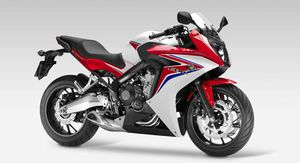
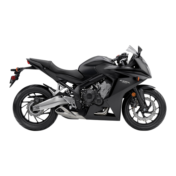
Honda CBR650F
Ниже представлены прямые ссылки на скачку сервисной документации.
Для Honda CBR650F
- Руководство пользователя (Owners Manual) на Honda CBR650F (на русском)
Обзор модели
- Honda CBR650F
Категории:
- Сервисная документация
- Honda документация