This device complies with Part 15 of the FCC Rules. Operation is subject to the following two
conditions: (1) This device may not cause harmful interference, and (2) this device must accept any
interference received, including interference that may cause undesired operation.
Modifications
The FCC requires the user to be notified that any changes or modifications made to this device that are
not expressly approved by Cat Eye Co., Ltd. may void the user’s authority to operate the equipment.
1
2
3
4
CAT EYE Cordless 7
CYCLOCOMPUTER CC-FR7CL
E OWNER’S MANUAL
®
Installation of Computer:
Secure bracket to handlebar with nylon ties (fig. A).
Slide computer into mount until it snaps in place.
Mount the wheel magnet to a spoke on the front
wheel (fig.B), so the magnet faces the sensor.
Secure the sensor to fork leg as shown (fig. C).
NOTE: The distance between the computer and the sen-
sor must not exceed 70 cm—if the sensor is too far
away from the computer head, the speed signal will not
register on the computer.
For best results, mount the sensor as high on the fork
leg as reasonably possible, so that the sensor is within
transmission range to the computer. However, the sen-
sor must be close enough to spokes to allow proper dis-
tance to magnet (see below).
Test by spinning the front wheel. Computer screen
should show speed. If not, make sure 1) the magnet is
close enough to sensor (within 5 mm); and 2) the sensor
is close enough to computer head (within 70 cm) and 3)
nothing is obstructing the line of sight between the sen-
IMPORTANT! PLEASE READ INSTRUCTIONS COMPLETELY
BEFORE ATTEMPTING TO INSTALL AND USE YOUR CAT EYE
CORDLESS 7 COMPUTER.
Cordless 7
U.S. Pat. Nos.4633216/4636769/4642606/5236759 Pat. and Design Pat. Pending
Copyright© 2002 CATEYE Co., Ltd.
CCMFR7CL-021210 Printed in Japan 066600165
1
2
3
OK
2
3
1
2
3
4
5
Bracket
Sensor
(Transmitter)
Magnet
Nylon Ties (L x 2)
Nylon Ties (S x 2)
Sensor Pulse Indicator
Magnet’s
center
Marking line
Less than 5mm
Spin
Max.
Distance
70 cm
1
3
2
NOTE: When the wheel rotates, the magnet MUST line up with the mark on the sensor.
ALSO NOTE: Magnet must pass within 5 mm of the sensor—if not, it will not trip the
sensor as it passes, and the computer will not register speed. Adjusting the sensor
position higher or lower on the fork leg or by rotating the sensor on the fork mount may
be required to achieve proper distance to the wheel magnet.
3
!
Press the SET button to lock in your choice—OR—
if you want to input previous mileage, hold the
MODE button (before pressing the SET button) for
2 seconds.
• Flashing Odometer digits will appear.
• MODE button increases the digit number.
• START/STOP button moves to the next digit.
• Press the SET button when complete.
Press All-Clear button (AC).
Computer Set-up (for first use, or after replacing battery)
Get your wheel
circumference
move to the next digit
• Stored data is erased.
• Computer power is started.
• Total Odometer read’s «zero».
• All digits shown then fades.
• Flashing «km/h» remains.
Adjust between “mph” or “km/h” by pressing
the MODE button.
• Wheel circumference number is shown.
• Look at chart to find TIRE SIZE in «mm».
• To increase TIRE SIZE press MODE button.
• To decrease press START/STOP button.
• 10-2999 mm can be registered.
• Press SET button when finished.
km/h
mph
Setup Completed (To Tm)
Tire Size
L(mm)
12 x1.75
935
14 x 1.50
1020
14 x 1.75
1055
16 x 1.50
1185
16 x 1.75
1195
18 x 1.50
1340
18 x 1.75
1350
20 x 1.75
1515
20 x 1-3/8
1615
22 x 1-3/8
1770
22 x 1-1/2
1785
24 x 1
1753
24 x 3/4Tubular
1785
24 x 1-1/8
1795
24 x 1-1/4
1905
24 x 1.75
1890
24 x 2.00
1925
24 x 2.125
1965
26 x 7/8
1920
26 x 1(59)
1913
26 x 1(65)
1952
26 x 1.25
1953
26 x 1-1/8
1970
26 x 1-3/8
2068
26 x 1-1/2
2100
26 x 1.40
2005
26 x 1.50
2010
26 x 1.75
2023
26 x 1.95
2050
26 x 2.00
2055
26 x 2.10
2068
26 x 2.125
2070
26 x 2.35
2083
26 x 3.00
2170
27 x 1
2155
27 x 1-1/8
2161
27 x 1-1/4
2161
27 x 1-3/8
2169
650 x 35A
2090
650 x 38A
2125
650 x 38B
2105
700 x 18C
2070
700 x 19C
2080
700 x 20C
2086
700 x 23C
2096
700 x 25C
2105
700 x 28C
2136
700 x 30C
2170
700 x 32C
2155
700C Tubular
2130
700 x 35C
2168
700 x 38C
2180
700 x 40C
2200
1
2
3
increase
the figure
increase
the figure
AC Button
decrease
the figure
Use the below table
as the rough guide.
The tire size is marked on
both sides of the tire.
AC button
SET button
ST./STOP button
MODE button
L mm
In this state Auto Time is ON.
ST./STOP
ST./STOP
MODE
MODE
MODE
SET
SET
SET
MODE
Precautions
• Do not concentrate too much on the computer operations while riding.
• Be sure to securely mount the magnet, sensor and bracket on your bicycle,
and alweys check to insure they are mounted securely.
• Used batteries must be disposed of properly and in accordance with all
local regulations.
• Never disassemble the computer.
• For cleaning, use mild soap and a soft cloth. Wipe dry with a soft cloth. Paint
thinner, benzine, alcohol or other chemicals may damage the surface.
About cordless system
The sensor picks up the wheel revolution signal and transmits the signal to the computer; the
computer calculates and displays the data on the screen.
CAUTION: In order to prevent external signal interference, the signal reception range is limited. For
best performance, the distance between the sensor and the computer must be kept within 70cm.
Attach the sensor at the upper part of your fork so that the distance becomes less than 70cm. The
signal reception range may shorten as a result of low temperature or lowered battery power.
In the following places and circumstances, interference may occur, resulting in malfunction:
• Near railroad crossing; in train cars.
• Near other cordless devices/television/personal computer/high power lighting system.
• Near the places where strong electromagnetic wave is generated; near television/ radio station; near
radar base.
• When being very close to another bicycle which also has a cordless cyclocomputer on its handlebar.
4
2
Sensor Screw
Sensor Base
Sensor Base
Front Fork
(fig. C)
(fig. B)
Spoke
5
1
Lever
Slide
Click
(fig. A)
Mounting View
Front Fork

This device complies with Part 15 of the FCC Rules. Operation is subject to the following two
conditions: (1) This device may not cause harmful interference, and (2) this device must accept any
interference received, including interference that may cause undesired operation.
Modifications
The FCC requires the user to be notified that any changes or modifications made to this device that are
not expressly approved by Cat Eye Co., Ltd. may void the user’s authority to operate the equipment.
1
2
3
4
CAT EYE Cordless 7
CYCLOCOMPUTER CC-FR7CLE OWNER’S MANUAL
®
Installation of Computer:
Secure bracket to handlebar with nylon ties (fig. A).
Slide computer into mount until it snaps in place.
Mount the wheel magnet to a spoke on the front
wheel (fig.B), so the magnet faces the sensor.
Secure the sensor to fork leg as shown (fig. C).
NOTE: The
distance between the computer and the sen-
sor must not exceed 70 cm—if the sensor is too far
away from the computer head, the speed signal will not
register on the computer.
For best results, mount the sensor as high on the fork
leg as reasonably possible, so that the sensor is within
transmission range to the computer. However, the sen-
sor must be close enough to spokes to allow proper dis-
tance to magnet (see below).
Test by spinning the front wheel. Computer screen
should show speed. If not, make sure 1) the magnet is
close enough to sensor (within 5 mm); and 2) the sensor
is close enough to computer head (within 70 cm) and 3)
nothing is obstructing the line of sight between the sen-
sor and the computer head.
IMPORTANT! PLEASE READ INSTRUCTIONS COMPLETELYBEFORE ATTEMPTING TO INSTALL AND USE YOUR CAT EYECORDLESS 7 COMPUTER.
U.S. Pat. Nos.4633216/4636769/4642606/5236759 Pat. and Design Pat. Pending
Copyright© 2002 CATEYE Co., Ltd.
CCMFR7CL-021210 Printed in Japan 066600165
1
2
3
OK
2
3
1
2
3
4
5
Bracket
Sensor
(Transmitter)
Magnet
Nylon Ties (L x 2)
Nylon Ties (S x 2)
Sensor Pulse Indicator
Magnet’s
center
Marking line
Less than 5mm
Spin
Max.
Distance
70 cm
1
3
2
NOTE: When the wheel rotates, the magnet MUST line up with the mark on the sensor.
ALSO NOTE:
Magnet must pass within 5 mm of the sensor—if not, it will not trip the
sensor as it passes, and the computer will not register speed. Adjusting the sensor
position higher or lower on the fork leg or by rotating the sensor on the fork mount may
be required to achieve proper distance to the wheel magnet.
3
!
Press the SET button to lock in your choice—OR—
if you want to input previous mileage, hold the
MODE button (before pressing the SET button) for
2 seconds.
• Flashing Odometer digits will appear.
• MODE button increases the digit number.
• START/STOP button moves to the next digit.
• Press the SET button when complete.
Press All-Clear button (AC).
Computer Set-up (for first use, or after replacing battery)Get your wheelcircumference
move to the next digit
• Stored data is erased.
• Computer power is started.
• Total Odometer read’s «zero».
• All digits shown then fades.
• Flashing «km/h» remains.
Adjust between “mph” or “km/h” by pressing
the MODE button.
•Wheel circumference number is shown.
• Look at chart to find TIRE SIZE in «mm».
• To increase TIRE SIZE press MODE button.
• To decrease press START/STOP button.
• 10-2999 mm can be registered.
• Press SET button when finished.
km/h mph
Setup Completed (To Tm)
Tire Size
L(mm)
12 x1.75 935
14 x 1.50 1020
14 x 1.75 1055
16 x 1.50 1185
16 x 1.75 1195
18 x 1.50 1340
18 x 1.75 1350
20 x 1.75 1515
20 x 1-3/8 1615
22 x 1-3/8 1770
22 x 1-1/2 1785
24 x 1 1753
24 x 3/4Tubular 1785
24 x 1-1/8 1795
24 x 1-1/4 1905
24 x 1.75 1890
24 x 2.00 1925
24 x 2.125 1965
26 x 7/8 1920
26 x 1(59) 1913
26 x 1(65) 1952
26 x 1.25 1953
26 x 1-1/8 1970
26 x 1-3/8 2068
26 x 1-1/2 2100
26 x 1.40 2005
26 x 1.50 2010
26 x 1.75 2023
26 x 1.95 2050
26 x 2.00 2055
26 x 2.10 2068
26 x 2.125 2070
26 x 2.35 2083
26 x 3.00 2170
27 x 1 2155
27 x 1-1/8 2161
27 x 1-1/4 2161
27 x 1-3/8 2169
650 x 35A 2090
650 x 38A 2125
650 x 38B 2105
700 x 18C 2070
700 x 19C 2080
700 x 20C 2086
700 x 23C 2096
700 x 25C 2105
700 x 28C 2136
700 x 30C 2170
700 x 32C 2155
700C Tubular 2130
700 x 35C 2168
700 x 38C 2180
700 x 40C 2200
1
2
3
increase
the figure
increase
the figure
AC Button
decrease
the figure
Use the below table
as the rough guide.
The tire size is marked on
both sides of the tire.
AC buttonSET button
ST./STOP button
MODE button
L mm
In this state Auto Time is ON.
ST./STOP
ST./STOP
MODE
MODE
MODE
SET
SET
SET
MODE
Precautions
•Do not concentrate too much on the computer operations while riding.
• Be sure to securely mount the magnet, sensor and bracket on your bicycle,
and alweys check to insure they are mounted securely.
• Used batteries must be disposed of properly and in accordance with all
local regulations.
•Never disassemble the computer.
• For cleaning, use mild soap and a soft cloth. Wipe dry with a soft cloth. Paint
thinner, benzine, alcohol or other chemicals may damage the surface.
About cordless system
The sensor picks up the wheel revolution signal and transmits the signal to the computer; the
computer calculates and displays the data on the screen.
CAUTION: In order to prevent external signal interference, the signal reception range is limited. For
best performance, the distance between the sensor and the computer must be kept within 70cm.
Attach the sensor at the upper part of your fork so that the distance becomes less than 70cm. The
signal reception range may shorten as a result of low temperature or lowered battery power.
In the following places and circumstances, interference may occur, resulting in malfunction:
• Near railroad crossing; in train cars.
•Near other cordless devices/television/personal computer/high power lighting system.
• Near the places where strong electromagnetic wave is generated; near television/ radio station; near
radar base.
•When being very close to another bicycle which also has a cordless cyclocomputer on its handlebar.
4
2
Sensor Screw
Sensor Base
Sensor Base
Front Fork
(fig. C)
(fig. B)
Spoke
5
1
Lever
Slide
Click
(fig. A)
Mounting View
Front Fork
Если у вас отсутствует техническая возможность для скачивания Руководство по эксплуатации для Cateye cordless 7 CC-FR7CL
вы можете прочесть документ прямо на нашем сайте или
Скачать Cateye cordless 7 CC-FR7CL Руководство по эксплуатации

- 1
- 2
- 3
Инструкции для прочих Cateye Наручные часы
Инструкции для прочих Cateye
Cateye Tomo CC-ST200 — Cyclocomputer Manual
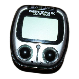
Device overview

- Main Display (Speed)
- Sensor Pulse Symbol
- Mode Symbol
- Speed Scale Symbol
- Auto Mode Symbol
- Sub-Display (Selected Function)
- M (Mode) Button
- S/S (Start/Stop) Butt
- Set Button
- Battery Case Cover
- Contact
MOUNTING TO BIKE
Mount main unit. If main display does not show any figures, press either M button or S/S button to release from power saving function. Spin the wheel to check if sensor pulse symbol flashes. If not, adjust relative positions of magnet and sensor following the instructions.
HOW TO REPLACE THE BATTERY
Turn main unit over, remove battery case cover with coin and insert a new lithium battery properly (CR1620 or CR1616) with the (+) pole upward (fig.17), and close the cover securely.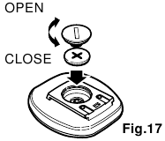
* Please make sure to do the All Clear operation after replacing battery, and to set the unit again.
BUTTON FUNCTION
M button (Fig.1)
Changes the display in the order shown in fig. 1, and data is displayed on the subdisplay. *If held over 2 seconds, 12-hour clock appears.
S/S button
Starts and stops the measurement of trip distance and elapsed time. During operation, speed scale symbol flashes. In Auto Function, this button is invalid.
SET Button
This is for setting the wheel circumference and clock time, switching on/off Auto Function and to clear all present data and any irregularity. When pressed in stop state in each mode, the following can be revised.
- In ODO mode — Wheel circumference
- In
 mode — 12-hour clock
 - In TM, DST or AVS mode — On/off the Auto function
 mode — 12-hour clock
Reset Operation: (Fig.2)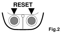
Select any mode except ODO, then press M button and S/S button simultaneously. MXS, AVS, DST and TM will become zero. (When done in ODO, registered wheel circumference will be displayed.)
All Clear Operation: (Fig.3)
When M button, S/S and set buttons are pressed simultaneously, all data stored (ODO, speed scale, Wheel circumference and clock time) is erased. All displays illuminate, then mile/h symbol illuminates. This should only be executed after replacing battery or when irregular display occurs due to static electricity, etc. Since all memories are erased, set necessary data Fig.3 again according to «Main Unit Preparation».
PARTS

- Bracket
- Wire
- Sensor
- Sensor Bands-A (S)(L)
- Sensor Bands-B
- Magnet
- Sensor Band Rubber Pad
- Bracket Rubber Pad (2 pcs.)
- Wire Securing Tape
- Sensor Band Screw
MAIN UNIT PREPARATION
The following must be completed before operating.
How to measure wheel circumference (L) of your bike
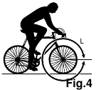
Put a mark on the tire tread and ride the bike one full wheel revolution. Mark the start and the end of the revolution on the ground and then measure the distance between the two marks. This is your actual circumference. Or, the «Selecting Values Cross Reference Table» tells you an approximate circumference according to tire size.
Setting Speed Scale
Preform all clear operation. All displays will illuminate. Then mile/h alone will be displayed as illustrated in fig.5. 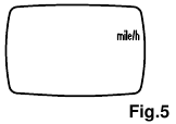
Km/h and mile/h are alternately displayed with each press of S/S button. Press M button to set desired speed scale. The display will change as fig. 6.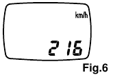
Setting the wheel circumference
(Fig.6)
The standard wheel circumference of 216 cm for 27″ wheel is displayed. When using 216 cm without revision, press M button. ODO will be displayed and 216 cm is set. For revision, press S/S button to increase the number by one. To increase rapidly, hold down the button. When the desired number appears, press M button. ODO will be displayed, and the desired number is set.
Resetting or changing the wheel circumference
Set main unit in ODO with M button, and stop it with S/S button. Press SET button. The stored number will flicker on the sub-display. Revise the number as desired according to the instructions in (3).
Setting the clock time

Press M button over 2 seconds to select  , and stop it with S/S button. Then press SET button, and minutes flash. Press S/S button to advance minutes by one. To advance rapidly, hold down the button. Set the time one or two minutes ahead of the current time. Then press M button, and hours will flash. Use S/S button the same way. Press SET button to complete time setting.
*When you press the SET button, the undisplayed seconds will turn to zero. For accuracy, set by the radio time signal.
MEASURING AND DISPLAY FUNCTIONS
 |
SPD Current Speed — 0.0(3.0) — 65 mile/h(27inch) ±1 mile/h under31 miles/h This is always displayed on the main display and updated once a second. |
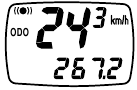 |
ODO Total Distance (Odometer) — 0.0 — 9999.9 mile ±0.1 mile This is continuously measured until battery wears down or all clear operation is done. At 10,000 miles(km), it returns to zero and counting begins anew. |
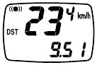 |
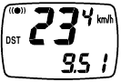
DST Trip Distance — 0.00 — 999.99 mile ±0.01 mile The trip distance from start to current point is displayed. With Reset operation, it returns to zero. |
 |
TM Elapsed Time — 0:00’00» — 9:59’59» ±0.003 % Elapsed time is measured from start to current point, in units of hours, minutes and seconds. At 10 hours, it returns to zero and counting begins anew. With Reset operation, it returns to zero. |
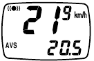 |
AVS Average Speed — 0.0 — 65.0mile/h ±0.3 mile/h The average speed from start to current point is displayed within 27 hours 46 minutes 39 seconds (99,999 seconds) or 999.99 miles (km). If either is exceeded, (.E) is displayed and calculation ceases. |
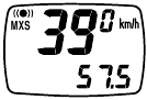 |
MXS Maximum Speed — 0.0(3.0) — 65 mile/h(27inch) ±1 mile/h With Reset operation, it returns to zero and counting begins anew. |
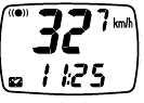 |
 12-hour clock time — 0:00′ — 11:59′ ±0.003 % 12-hour clock time — 0:00′ — 11:59′ ±0.003 %The current time is displayed by a 12-hour clock. |
AUTO (AUTOMATIC START/STOP) FUNCTION
This function switches the main unit to start or stop automatically, in which AUTO symbol appears on the screen, and you are free from pressing S/S button each
- How to switch on/off the Auto Function.
In TM, DST or AVS, this function switches on/off with each press of SET button. When on, AUTO symbol appears. *With this function, it ceases measuring elapsed time during a stop.
* 2 seconds may be elapsed if mount the main unit to the bracket with this function on.
POWER SAVING FUNCTION

When main unit is left without receiving any signal for 60-70 minutes continuously, power supply is shut down and main unit will display (  ) only as the figure. By pressing M button or S/S button, or by receiving signal, this function is released.
TROUBLE SHOOTING
- The following situations do not indicate malfunction of the cyclocomputer. Check the following before taking to repair.
* When current speed does not appear, short-circuit the contact on the back with metal. The unit will function normally if the speed display appears.
Display response is slow.
- Is it at a low temperature under 32°F(0°C)?
- It returns to normal state when temperature rises.
No display.
- Has the Lithium Battery in the main unit worn out?
- Replace the Lithium Battery with a new one.
Incorrect data appear.
- Execute «All Clear» operation.
Current speed does not appear.
- Is there anything on the contact of the main unit or of the bracket?
- Wipe the contact clean.
- Is the distance between sensor and magnet too far?
- Are the marking line of the sensor and the center of magnet matched each other?
- Refer to «Sensor/Magnet Mounting» and re-adjust correctly.
- Is the wire broken?
- Replace the Bracket & Sensor part with a new one.
Transmission signal loss in damp or wet conditions.
- Water or condensation may collect between the bracket sensor and the computer causing an interruption in the data transmission. Wipe the contacts with dry cloth. Contacts can also be treated with a water repellent silicon jell from an automotive parts or hardware store. Do not use industrial water repellent; it may damage the bracket.
When the S/S button is pressed, the unit doesn’t activate or stop.
- Is the unit in the Auto function?
- The S/S button doesn’t function in the Auto function.
MAINTENANCE/PRECAUTIONS
- Do not leave the main unit exposed to direct sunlight when the unit is not in use.
- Do not disassemble the main unit, sensor and magnet.
- Don’t pay too much attention to your computer’s functions while riding! Keep your eyes on theroad and duly consider to traffic safety.
- Check relative position of sensor and magnet periodically.
- For cleaning, use neutral detergent on soft cloth, and wipe off later with dry cloth. Do not applypaint thinner, benzine, or alcohol, to avoid damages on the surface.
- If there is mud, sand or the like clogs between the button and the body, the movement of thebutton may be disturbed. Softly wash away such objects with water.
SPECIFICATIONS
| Applicable Cycle Sizes | 130cm — 229cm |
| Applicable Fork Diameter | 11ø — 36ø (S:11 — 26ø L:21 — 36ø) |
| The length of the wire | 70cm |
| Power Supply | Lithium Battery (CR1620/CR1616) x 1 |
| Battery Life | Approx. 3 years(The life of the first factory-loaded battery may be shorter than this period.) |
| Dimension/Weight | 1-15/16″ x 1-25/32″ x 5/8″ (49 x 45 x 16 mm) / 0.74 oz (21 g) |
| Controller | 4-bit 1-chip Microcomputer (Crystal Controlled Oscillator) |
| Display | Liquid Crystal Display |
| Sensor | No Contakt Magnetic Sensor |
| Operating Temperature Range | 0°C — 40°C(32°F — 104°F) |
* The specifications and design are subject to change without notice.
Setting Values Cross Reference Table
(The tire size is marked on both sides of the tire.)
| TIRE SIZE | TIRE SIZE | TIRE SIZE | |||
| 20 x 1.75 | 150 | 26 x 1.40 | 200 | 650 x 38B | 211 |
| 24 x 1 | 175 | 26 x 1.50 | 199 | 700 x 18C | 207 |
| 24 x 3/4 Tubular | 178 | 26 x 1.75 | 202 | 700 x 19C | 209 |
| 24 x 1-1/8 Tubular | 179 | 26 x 1.95 | 205 | 700 x 20C | 209 |
| 24 x 1-1/4 | 191 | 26 x 2.00 | 206 | 700 x 23C | 210 |
| 24 x 1.75 | 189 | 26 x 2.1 | 207 | 700 x 25C | 211 |
| 24 x 2.00 | 192 | 26 x 2.125 | 207 | 700 x 28C | 214 |
| 24 x 2.125 | 196 | 26 x 2.35 | 208 | 700 x 30C | 217 |
| 26 x 1(559mm) | 191 | 27 x 1 | 215 | 700 x 32C | 216 |
| 26 x 1(650c) | 195 | 27 x 1-1/8 | 216 | 700C Tubular | 213 |
| 26 x 1.25 | 195 | 27 x 1-1/4 | 216 | 700 x 35C | 217 |
| 26 x 1-1/8 Tubular | 197 | 27 x 1-3/8 | 217 | 700 x 38C | 218 |
| 26 x 1-3/8 | 207 | 650 x 35A | 209 | 700 x 44C | 222 |
| 26 x 1-1/2 | 210 | 650 x 38A | 212 |

Documents / Resources
Download manual
Here you can download full pdf version of manual, it may contain additional safety instructions, warranty information, FCC rules, etc.
Download Cateye Tomo CC-ST200 — Cyclocomputer Manual
Смотреть руководство для Cateye Cordless 7 CC-FR7CL ниже. Все руководства на ManualsCat.com могут просматриваться абсолютно бесплатно. Нажав кнопку «Выбор языка» вы можете изменить язык руководства, которое хотите просмотреть.

MANUALSCAT | RU
Вопросы и ответы
У вас есть вопрос о Cateye Cordless 7 CC-FR7CL, но вы не можете найти ответ в пользовательском руководстве? Возможно, пользователи ManualsCat.com смогут помочь вам и ответят на ваш вопрос. Заполните форму ниже — и ваш вопрос будет отображаться под руководством для Cateye Cordless 7 CC-FR7CL. Пожалуйста, убедитесь, что вы опишите свои трудности с Cateye Cordless 7 CC-FR7CL как можно более детально. Чем более детальным является ваш вопрос, тем более высоки шансы, что другой пользователь быстро ответит на него. Вам будет автоматически отправлено электронное письмо, чтобы проинформировать вас, когда кто-то из пользователей ответит на ваш вопрос.
Задать вопрос о Cateye Cordless 7 CC-FR7CL
- Бренд:
- Cateye
- Продукт:
- велокомпьютеры
- Модель/название:
- Cordless 7 CC-FR7CL
- Тип файла:
- Доступные языки:
- английский