- Manuals
- Brands
- Carrier Manuals
- Utility Vehicle
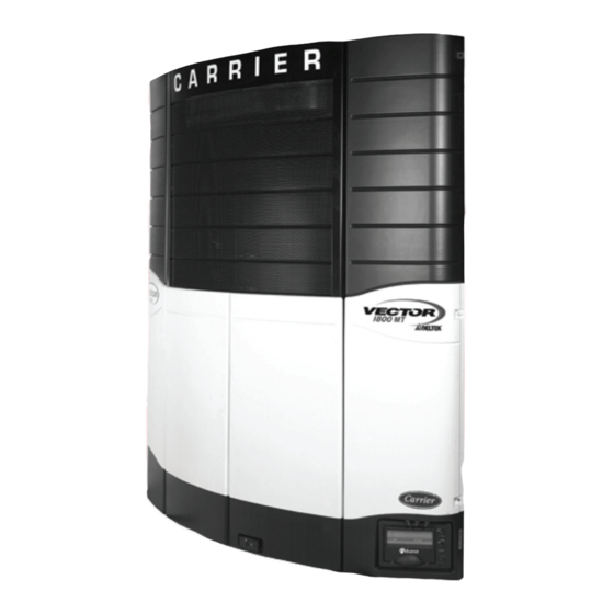
- VECTOR 1800 MT
- Operation & service manual
-
Contents
-
Table of Contents
-
Bookmarks
Quick Links
Related Manuals for Carrier VECTOR 1800 MT

Summary of Contents for Carrier VECTOR 1800 MT
-
Page 2
OPERATION & SERVICE MANUAL VECTOR 1800 MT Trailer Multi—Temp Refrigeration Units… -
Page 3
TABLE OF CONTENTS PARAGRAPH NUMBER Page SAFETY PRECAUTIONS …………..SAFETY PRECAUTIONS . -
Page 4
TABLE OF CONTENTS (Continued) PARAGRAPH NUMBER Page OPERATION …………….. RS “ON”… -
Page 5
TABLE OF CONTENTS (Continued) PARAGRAPH NUMBER Page Temperature Range Lock 1 & 2 …………ProductShieldt . -
Page 6
TABLE OF CONTENTS (Continued) PARAGRAPH NUMBER Page SHUTDOWN ALARMS …………..LOW ENGINE OIL PRESSURE . -
Page 7
TABLE OF CONTENTS (Continued) PARAGRAPH NUMBER Page ELECTRICAL ALARMS …………..7-38 BAD F2 OR F3 FUSE . -
Page 8
TABLE OF CONTENTS (Continued) PARAGRAPH NUMBER Page SENSOR ALARMS …………..7-57 CHECK AMBIENT AIR SENSOR . -
Page 9
TABLE OF CONTENTS (Continued) PARAGRAPH NUMBER Page PRE- -TRIP ALARMS (Continued) …………7-67 P175 CHECK HIGH SPEED RPM . -
Page 10
TABLE OF CONTENTS (Continued) PARAGRAPH NUMBER Page 7.11 MICROPROCESSOR ALARMS …………7-114 SETPOINT ERROR . -
Page 11
TABLE OF CONTENTS (Continued) PARAGRAPH NUMBER Page BATTERY CHARGER …………..8-12 8.8.1 Description . -
Page 12
TABLE OF CONTENTS (Continued) PARAGRAPH NUMBER Page 8.23 COMPRESSOR SUCTION MODULATION VALVE (CSMV) ……. . 8-33 8.23.1 Function . -
Page 13: Table Of Contents
LIST OF ILLUSTRATIONS FIGURE NUMBER Page Figure 2-1. Front View …………… Figure 2-2.
-
Page 14
LIST OF ILLUSTRATIONS (Continued) FIGURE NUMBER Page Figure 8—29 Electronic Expansion Valve …………8-27 Figure 8—30 Electronic expansion valve . -
Page 15
SAFETY PRECAUTIONS Engine Coolant 1.1 SAFETY PRECAUTIONS Your Carrier Transicold refrigeration unit has been designed with the safety of the operator in mind. During The engine is equipped with a pressurized cooling normal operation, all moving parts are fully enclosed to system. -
Page 16
WARNING WARNING Do not connect to any electrical outlet Be aware of HIGH VOLTAGE (up to 599V) without checking that it meets the supplied by the generator as the unit may 460/3/60 and 23 Amp electrical start automatically. Before servicing the requirements of the unit. -
Page 17
WARNING tion. If you know the repair location time zone, enter that time. If you don’t, enter Carrier Transicold does not recommend al- your current time. lowing the compressor to pull less than 0 Bar/PSIG at any time. -
Page 18
CAUTION CAUTION Use only ethylene glycol anti-freeze (with Extreme care must be taken to ensure the inhibitors) in system as glycol by itself will manifold common connection remains im- damage the cooling system. Always add mersed in oil at all times; otherwise, air and pre-mixed 50/50 anti-freeze and water to ra- moisture will be drawn into compressor. -
Page 19
1.3 SAFETY DECALS 62-11039… -
Page 20
62—03958—00 Heat Warning 62—03957—01 High Voltage 62—60280—00 Standby Safety 62-11039… -
Page 21
62-11039… -
Page 22: Table 2-1. Model Chart
SECTION 2 UNIT DESCRIPTION 2.1 INTRODUCTION This manual contains operating data, electrical data and WARNING service instructions for the Vector 1800MT refrigeration system. Be aware of HIGH VOLTAGE supplied by the Additional support manuals are listed in Table 2-3. generator unit start automatically.
-
Page 23: Table 2-3. Additional Support Manuals
Table 2-3. Additional Support Manuals Manual Number Equipment Covered Type of Manual 62—11038 Vector 1800MT & 06D Compressor Service Parts List 62—11040 Vector 1800MT Operator’s Manual 62—11041 Vector 1800M Easy To Run 62—11095 CT4-134DI-E2B Engine Parts List 62—10865 CT4-134DI-E2B Engine Workshop Manual 2.2 GENERAL DESCRIPTION The VECTOR 1800MT unit is a hybrid diesel/electric,…
-
Page 24: Figure 2-1. Front View
Fuel filter Engine oil pressure switch (ENOPS) Model/Serial number nameplate Download Port Battery Display and Keypad Battery charger Fuel solenoid (FS) Generator Speed control solenoid (SCS) Engine RPM (ENRPM) Control box Lube oil filter Engine coolant temperature (ENCT) Oil drain Air cleaner Starter motor Coolant bottle…
-
Page 25: Figure 2-2. Front View
Condenser/Radiator Front unloader solenoid valve Defrost air switch (DAS) Compressor, Compressor discharge tempera- Receiver and sight glasses ture (CDT), Rear unloader solenoid, Compressor Shutoff (King) valve electrical box (Located on rear of compressor) Compressor suction modulation valve (CSMV) Suction service valve Filter drier Compressor sight glass Compressor suction temperature (CST)
-
Page 26: Figure 2-3 Evaporator Section — Grille Removed
Evaporator fans and motors Return air thermistor sensor (1RAT) Nozzle cover Electronic expansion valve (EVXV) Defrost termination thermostat sensor (1DTT) Evaporator outlet temperature sensor (EVOT) Evaporator Coil Electric heaters Drain pan heater Remote evaporator liquid line connection Heat Exchanger Remote evaporator suction line connection Remote suction and liquid lines Supply air temperature sensor (1SAT) Evaporator outlet pressure sensor (EVOP…
-
Page 27: Figure 2-4 Control Box
INSIDE LEFT SIDE OF BOX Compartment 2 evaporator contactor (2EVCON) Compartment 3 evaporator contactor (3EVCON) Compartment 2 heater contactor 1 (2HTCON1) Compartment 1 heater contactor 1 (HTCON1) Compartment 2 heater contactor 2 (2HTCON2) Microprocessor power fuse (F6) Compartment 3 heater contactor 1 (3HTCON1) Contactor power fuse (F9) Compartment 3 heater contactor 2 (3HTCON2) Run control relay (RCR)
-
Page 28
2.3 CONDENSING SECTION The condensing section (Figure 2-2) consists of an 2.3.3 Compressor engine—compressor drive package, condenser fan, condenser/radiator coil, refrigerant controls, piping, The compressor assembly includes the refrigerant com- wiring, defrost air switch, and associated components. pressor, suction and discharge service valves, high pressure switch, compressor discharge thermistor and The drive equipment includes the engine, generator, air the suction and discharge pressure transducers. -
Page 29: Figure 2-5. Compressor Cylinder Head Unloaded
Solenoid Valve Strainer Valve Stem Suction Manifold Gas Bypass Port Cylinder Discharge Valve Spring Guide Valve Plate Spring Cylinder Suction Valve Piston Discharge Piston Check Valve Assembly Piston Bypass Valve Discharge Manifold Bleed Orifice Figure 2-5. Compressor Cylinder Head Unloaded b.
-
Page 30: Figure 2-6. Compressor Cylinder Head Loaded
Solenoid Valve Strainer Valve Stem Suction Manifold Gas Bypass Port Cylinder Discharge Valve Spring Guide Valve Plate Spring Cylinder Suction Valve Piston Discharge Piston Check Valve Assembly Piston Bypass Valve Discharge Manifold Bleed Orifice Figure 2-6. Compressor Cylinder Head Loaded c.
-
Page 31
2.3.6 Transducers and Sensors valve has a dual function — automatic expansion control and prevention of liquid return to the compressor. a. Compressor Suction Pressure Transducer (CSP) 2.4.2 Heat Exchanger Provides micro with suction pressure information to be displayed, recorded in the data recorder and used to control the refrigeration system. -
Page 32
Automated Micro Self—test 2.6 SYSTEM OPERATING CONTROLS AND COMPONENTS Data Recorder The temperature controller is a Carrier Transicold Data Recorder date & time can be set from the Keypad Advance Microprocessor controller (Refer to Section Auto Start—Stop 2.6.3 and 3). Once the controller is set at the desired… -
Page 33
CAUTION Under no circumstances should anyone attempt to repair the Logic or Display Boards. Should a problem develop with either of these components, contact your nearest Carrier Transicold dealer for replacement. a. Control Module Figure 2-7 shows the Control Module. The Control… -
Page 34: Figure 2-7. Control Module
RUN RELAY (K2) SPEED RELAY (K1) QC5 (NOT LED29 USED) (7.5A) QC4 (+12V OUTPUT QC3 (+12V OUTPUT TO RR) TO SR) USED LED28 LED27 F3 (7.5A) F2 (10A) PC CARD FAULT LED RELAY POWER (RED) QC8 (12+ VDC 1MP (WHITE) TEMP &…
-
Page 35: Table 2-4. Field Effect Transistors
Table 2-4. FIELD EFFECT TRANSISTORS (Transistors not listed are spares) STANDARD DESIGNATION FET1 Condenser fan motor FET2 Compressor contactor FET3 Generator contactor FET10 Heat contactor 1 FET18 Buzzer FET19 Standby contactor FET20 Evaporator motor FET21 Heat contactor 2 FET22 Rear unloader FET23 Front unloader LIGHT BAR OPTIONS…
-
Page 36: Figure 2-8. Display And Keypad
DOOR CLOSED Compartments ON/OFF switches Alarm list key Mode lights Start/Stop—Continuous key Main Display Select key MessageCenter Start/Run—Stop switch (RS) Up and Down arrow keys Standby/Engine switch Enter key Manual defrost key Figure 2-8. Display And Keypad 62-11039 2-15…
-
Page 37
Display MessageCenter The Main Display has 9 characters (7 seven—segment The MessageCenter is used to show messages. Details characters and 2 nine—segment characters), 2 decimal of the messages are described in Section 6.1 points, 2 commas, and a degree symbol. The display is MessageCenter. -
Page 38
Key Descriptions SELECT Key SELECT Press the SELECT key to scroll through the menu selections. One of the five standard UP ARROW and DOWN ARROW Keys and 1 optional menu selections will appear in the MessageCenter when the SELECT key is pressed. These are: TO VIEW These keys allow you to change the HOURMETERS, TO START PRETRIP, TO setpoints or other displayed data of the… -
Page 39: Figure 2-9. Ogf Module
2.7 ELECTRONIC MODULES 2.7.1 Overload Ground Fault Module (OGF) OPTIONS 2.8.1 Light Bar The Light Bar is an external set of indicator lights which can be seen in the mirror from the cab of the tractor. They are controlled by the microprocessor. The green LED indicates “STATUS OK”.
-
Page 40
2.8.3 Out of Range Alarm 2.8.4 Remote Control Panel The Out Of Range Alarm is intended to notify the driver User-friendly indicator and operator control panels when the box temperature is moving away from Set clearly show individual compartment temperatures with Point. -
Page 41: Table 2-5. Engine Data
2.9 ENGINE DATA Table 2-5. Engine Data Engine Model V2203—DI—E2B—CTD—5S1 Displacement 134 in 2.197 liters) No. Cylinders Rated Horsepower 35 hp (26.1KW) @1850 rpm NOTE: See Table 2-1 for actual engine RPM settings Weight 417.8 lbs (189.5 kg) Coolant Capacity 2 gallons (7.6 liters) (50/50 mix — never to exceed 60/40) Starts to open 177 to 182°F (81 to 83°C ) Thermostat…
-
Page 42: Table 2-6. Compressor Data
2.11 COMPRESSOR DATA 2.12 REFRIGERATION SYSTEM DATA a. Defrost Air Switch (DAS) Table 2-6. Compressor Data Initiates Defrost: Compressor Model 1.40 ¦ .07 inch WG (35 ¦ 1.8 mm) b. Defrost Timer (micro controlled) No. Cylinders 1.5h, 3h, 6h, or 12 hours No.
-
Page 43
2.13 ELECTRICAL DATA ELECTRICAL DATA Rating: 40amps @460 VAC System current limit — high speed: 26 amps Full Load Amps (FLA) Full Load Amps (FLA) Compressor Motor Compressor Motor System current limit — low speed: 22 amps Locked Rotor Locked rotor amps: 77 at 460V Full Load Amps (FLA) 1.5 amps @ 65 Hz Horsepower… -
Page 44: Table 2-7. Component Resistance & Current Draw
2.14 COMPONENT RESISTANCE & CURRENT DRAW Table 2-7. Component Resistance & Current Draw Component Ohms Amps Unloader 10.6 ± 0.3 Ohms 1.0 to 2.0 Amps Speed solenoid (SCS) 1.5 to 2.5 Ohms 3.0 — 8.0 Amps 12VDC Relay 72 Ohms ±10% 0.14 — 0.18 Amps 10—00328—00 12VDC Relay…
-
Page 45
2.16 REFRIGERANT CIRCUIT DURING COOLING (See Figure 2-11 thru Figure 2-14) When cooling, the unit operates as a vapor compression pressure of the liquid and meters the flow of liquid refrigeration system. The main components of the refrigerant to the evaporator to obtain maximum use of system are: the (1) reciprocating compressor, (2) the evaporator heat transfer surface. -
Page 46: Figure 2-11. Refrigerant Circuit All Compartments Cooling
LSV3 EXTERNAL EQUALIZER BULB REMOTE EVAPORATOR LSV2 EXTERNAL EQUALIZER BULB REMOTE EVAPORATOR EVXV RELIEF VALVE RECEIVER HOST EVAPORATOR EVOP EVOT MANUAL SHUT- -OFF VALVE HEAT EXCHANGER CSMV LIQUID LINE FILTER DRIER SUBCOOLER DISCHARGE SERVICE VALVE SUCTION SERVICE VALVE CONDENSER COMPRESSOR DISCHARGE DISCHARGE LIQUID…
-
Page 47: Figure 2-12. Refrigerant Circuit — Compartment One Cooling, Compartments 2 & 3 Heating
LSV3 EXTERNAL EQUALIZER BULB REMOTE EVAPORATOR LSV2 EXTERNAL EQUALIZER BULB REMOTE EVAPORATOR EVXV RELIEF VALVE RECEIVER HOST EVAPORATOR EVOP EVOT MANUAL SHUT- -OFF VALVE HEAT EXCHANGER CSMV LIQUID LINE FILTER DRIER SUBCOOLER DISCHARGE SERVICE VALVE SUCTION SERVICE VALVE CONDENSER COMPRESSOR DISCHARGE LIQUID HOT GAS LINE…
-
Page 48: Figure 2-13. Refrigerant Circuit — Compartments One And Two Cooling, Compartment 3 Heating
LSV3 EXTERNAL EQUALIZER BULB REMOTE EVAPORATOR LSV2 EXTERNAL EQUALIZER BULB REMOTE EVAPORATOR EVXV RELIEF VALVE RECEIVER HOST EVAPORATOR EVOP EVOT MANUAL SHUT- -OFF VALVE HEAT EXCHANGER CSMV LIQUID LINE FILTER DRIER SUBCOOLER DISCHARGE SERVICE VALVE SUCTION SERVICE VALVE CONDENSER COMPRESSOR DISCHARGE LIQUID HOT GAS LINE…
-
Page 49: Figure 2-14. Refrigerant Circuit — Compartments One And Three Cooling, Compartment 2 Heating
LSV3 EXTERNAL EQUALIZER BULB REMOTE EVAPORATOR LSV2 EXTERNAL EQUALIZER BULB REMOTE EVAPORATOR EVXV RELIEF VALVE RECEIVER HOST EVAPORATOR EVOP EVOT MANUAL SHUT- -OFF VALVE HEAT EXCHANGER CSMV LIQUID LINE FILTER DRIER SUBCOOLER DISCHARGE SERVICE VALVE SUCTION SERVICE VALVE CONDENSER COMPRESSOR DISCHARGE LIQUID HOT GAS LINE…
-
Page 50: Figure 2-15. Refrigerant Circuit — All Compartments Heating
LSV3 EXTERNAL EQUALIZER BULB REMOTE EVAPORATOR LSV2 EXTERNAL EQUALIZER BULB REMOTE EVAPORATOR EVXV RELIEF VALVE RECEIVER HOST EVAPORATOR EVOP EVOT MANUAL SHUT- -OFF VALVE HEAT EXCHANGER CSMV LIQUID LINE FILTER DRIER SUBCOOLER DISCHARGE SERVICE VALVE SUCTION SERVICE VALVE CONDENSER COMPRESSOR Figure 2-15.
-
Page 51
SECTION 3 OPERATION 3.1 RS “ON” AND ALL COMPARTMENT SWITCHES “OFF” 1. When all compartment switches are in “OFF” (0) position and RS is in “START/RUN” position. COMPARTMENT SWITCHES COMPARTMENT 3 COMPARTMENT 2 COMPARTMENT 1 MAIN DISPLAY will display 2. The START/RUN — OFF switch is in “OFF”… -
Page 52
3.2 STARTING UNIT — — ENGINE/ROAD OPERATION WARNING Under no circumstances should ether or any other starting aids be used to start engine. COMPARTMENT SWITCHES COMPARTMENT 3 COMPARTMENT 2 COMPARTMENT 1 1. Place the desired compartment switch(es) in ON (1) position. 2. -
Page 53
3.3 STARTING UNIT — — ELECTRIC STANDBY OPERATION WARNING When performing service and/or maintenance procedures, make certain the unit is disconnected from the power source and that the RS is in OFF position so that it is impossible for the unit to start up automatically during the maintenance operation. -
Page 54
NOTE The unit is equipped with automatic phase re- versal which insures that the electric motors will run in the correct direction. For safe, reliable operation in electric standby mode, it is important to consider the following guidelines: • NEVER connect the unit to a high voltage power source with the RS in the START/RUN position. -
Page 55
TARTUP — — NGINE/ OAD AND LECTRIC TANDBY 8888888888888 STANDBY ENGINE SELF TEST When first powered up: • The MessageCenter will display the default mes- sage, unless there is an alarm(s) stored in the con- • The microprocessor controller will run a self test. troller. -
Page 56
3.5 PRETRIP 1. Place RS in “START/RUN” position. HEAT COOL DEFROST ALARM START-STOP CONTINUOUS PPPP SETPOINT BOX TEMPERATURE TEST #1 MANUAL SELECT ALARM LIST START- — STOP/ DEFROST CONTINUOUS 2. Press the SELECT key until the MessageCenter displays “PRESS THE = KEY TO START PRETRIP” 3. -
Page 57
PRETRIP (Continued) NOTE Test 2 — — Amperage Check of 12VDC Electrical Components Pretrip will run until completed, unless an alarm occurs that causes Pretrip to be aborted. Only alarms that will Check the amperage (current) draw of the following components: result in other erroneous alarms or will affect future Pretrip tests will allow Pretrip to be aborted. -
Page 58
PRETRIP (Continued) Test 4 — — Temperature Sensor Check Test 9 — — Evaporator Fan Motors Amperage Check (All Compartments) Check the condition of all of the system temperature Will energize each evaporator motor contactor sensors. individually and check for proper current draw. An alarm will be displayed for any fan motors testing outside the current range (amps). -
Page 59
3.6 CHANGING SETPOINT 1. Wait for desired compart- ment to be displayed. HEAT COOL DEFROST ALARM START-STOP CONTINUOUS +36 F SETPOINT BOX TEMPERATURE SETPOINT CHANGED MANUAL SELECT ALARM LIST START- — STOP/ DEFROST CONTINUOUS 2. With the setpoint of the desired compartment displayed, press the UP ARROW or DOWN ARROW key to change the setpoint to the desired value. -
Page 60
3.7 START- -STOP OPERATION — — ENGINE/ROAD AND ELECTRIC STANDBY START—STOP LIGHT HEAT COOL DEFROST ALARM START-STOP CONTINUOUS +36 F SETPOINT BOX TEMPERATURE START/STOP MODE SELECTED MANUAL SELECT ALARM LIST START- — STOP/ DEFROST CONTINUOUS 1. Press the START—STOP/CONTINUOUS key until the START—STOP Light on the controller illumi- nates. -
Page 61
3.8 CONTINUOUS RUN OPERATION CONTINUOUS RUN LIGHT HEAT COOL DEFROST ALARM START-STOP CONTINUOUS +36 F SETPOINT BOX TEMPERATURE CONTINUOUS RUN MODE SELECTED MANUAL SELECT ALARM LIST START- — STOP/ DEFROST CONTINUOUS 1. Press the START-STOP/CONTINUOUS key until the CONTINUOUS RUN 2. -
Page 62
3.9 SLEEP MODE ON/OFF Sleep Mode ON HEAT COOL DEFROST ALARM START-STOP CONTINUOUS SETPOINT BOX TEMPERATURE SLEEP MODE: YES MANUAL SELECT ALARM LIST START- — STOP/ DEFROST CONTINUOUS 1. Press the SELECT key until the MessageCenter displays “PRESS ↑↓ TO VIEW SETTINGS”. 2. -
Page 63
SLEEP MODE ON (Continued) If Sleep Mode is selected, when the unit is not running NOTE (FOR ENGINE OPERATION ONLY) (Start-Stop Off Cycle), any remaining Minimum Off In the event that the Engine Coolant Tempera- Time will be ignored, and the engine will start. It will run ture sensor fails, Sleep Mode will operate as fol- for 4 minutes (minimum), until the Engine Coolant lows:… -
Page 64
3.10 MANUAL DEFROST DEFROST LIGHT HEAT COOL DEFROST ALARM START-STOP CONTINUOUS SETPOINT BOX TEMPERATURE DEFROST CYCLE STARTED MANUAL SELECT ALARM LIST START- — STOP/ DEFROST CONTINUOUS 1. Press the MANUAL DEFROST key. The DEFROST light will come on and the MessageCenter will display “DEFROST CYCLE STARTED” for 5 seconds, or flash “CANNOT START DEFROST CYCLE”… -
Page 65
3.11 TRIP START HEAT COOL DEFROST ALARM START-STOP CONTINUOUS +36 F SETPOINT BOX TEMPERATURE TRIP START ENTERED MANUAL SELECT ALARM LIST START- — STOP/ DEFROST CONTINUOUS 1. To mark the start of a trip in the data recorder, press the SELECT key until The MessageCenter displays “PRESS = TO MARK TRIP START”. -
Page 66
3.12 VIEW ACTIVE ALARMS ALARM LIGHT HEAT COOL DEFROST ALARM START-STOP CONTINUOUS +36 F SETPOINT BOX TEMPERATURE NO ACTIVE ALARMS MANUAL SELECT ALARM LIST START- — STOP/ DEFROST CONTINUOUS 1. Press the ALARM LIST key. If there are no active alarms, the display will say “NO ACTIVE ALARMS”… -
Page 67
3.13 VIEW INACTIVE ALARMS HEAT COOL DEFROST ALARM START-STOP CONTINUOUS +36 F SETPOINT BOX TEMPERATURE NO INACTIVE ALARMS MANUAL SELECT ALARM LIST START- — STOP/ DEFROST CONTINUOUS 1. Press and hold both the ALARM LIST key and the UP ARROW key for 6 seconds. -
Page 68
3.14 UNIT DATA HEAT COOL DEFROST ALARM START-STOP CONTINUOUS +36 F SETPOINT BOX TEMPERATURE PRESS ↑ ↓ TO VIEW DATA MANUAL SELECT ALARM LIST START- — STOP/ DEFROST CONTINUOUS 1. Press the SELECT key until the MessageCenter displays “PRESS ↑↓ TO VIEW DATA”. 2. -
Page 69: Table 3-1. Unit Data
Table 3-1. UNIT DATA * Also appear in Configurations + May or may not be displayed depending on functional parameter settings DATA DEFINITION SUCTION PRESSURE Compressor suction pressure DISCHARGE PRESSURE Compressor discharge pressure EVAPORATOR PRESSURE Suction pressure in the evaporator section ENGINE COOLANT TEMP Engine coolant temperature RETURN AIR TEMP…
-
Page 70
Table 3-1. UNIT DATA * Also appear in Configurations + May or may not be displayed depending on functional parameter settings UNIT MODEL # Unit model number (selected through configurations) + HOURS TO ENGINE Number of engine hours until the next programmed engine maintenance. MAINT + HOURS TO S/B MTR Number of engine hours until the next programmed electric standby mo-… -
Page 71
Table 3-1. UNIT DATA * Also appear in Configurations + May or may not be displayed depending on functional parameter settings REMOTE SENSOR (1—3) This is the temperature at remote Temperature Sensor 1, 2, and 3. (These sensors are optional, and may not be applicable to your unit. Up to 3 remote sensors may be listed.) DATALOGGER This is the current Date and Time that the Data Recorder is using. -
Page 72
3.15 VIEW HOURMETERS HEAT COOL DEFROST ALARM START-STOP CONTINUOUS +36 F SETPOINT BOX TEMPERATURE TOTAL ENGINE HOURS: 0 HRS MANUAL SELECT ALARM LIST START- — STOP/ DEFROST CONTINUOUS 1. Press the SELECT key until the MessageCenter displays “PRESS ↑↓ TO VIEW HOURMETERS”. 2. -
Page 73
3.16 FUNCTIONAL CHANGE (PARAMETERS) HEAT COOL DEFROST ALARM START-STOP CONTINUOUS +36 F SETPOINT BOX TEMPERATURE PRESS ↑ ↓ TO VIEW SETTINGS MANUAL SELECT ALARM LIST START- — STOP/ DEFROST CONTINUOUS 1. Press the SELECT key until the MessageCenter displays “PRESS ↑↓ TO VIEW SETTINGS”. 2. -
Page 74: Table 3-2. Functional Parameters
Table 3-2. Functional Parameters FUNCTIONAL DESCRIPTION SELECTIONS PARAMETER NO — Normal engine speed operation. SILENT MODE YES — Low engine speed operation. The defrost timer will automatically put the unit into the defrost cycle at DEFROST 1.5HRS INTERVAL TIMER 3HRS the interval selected if any one compartment DTTS is below 40°F SET FOR 6HRS…
-
Page 75
FUNCTIONAL DESCRIPTION SELECTIONS PARAMETER FROZEN SHUT- This only applies to Frozen Setpoints in Start—Stop operation. ° F (0 ° This offset is the number of degrees below setpoint that the unit will DOWN OFFSET run before cycling off. This will allow for a lower average refrigerated °… -
Page 76
FUNCTIONAL DESCRIPTION SELECTIONS PARAMETER SLEEP MODE NO — is the normal operating selection. YES— selects Sleep Mode. In this mode the unit will operate only as needed to keep the engine warm, and the battery charged. There is NO TEMPERATURE CONTROL in Sleep Mode. * OVERRIDE NO — allows the door switch to shut the unit down whenever the refrig- DOOR… -
Page 77
3.17 LANGUAGE SELECTION HEAT COOL DEFROST ALARM START-STOP CONTINUOUS +36 F SETPOINT BOX TEMPERATURE ESPAÑOL MANUAL SELECT ALARM LIST START- — STOP/ DEFROST CONTINUOUS 1. Press and hold the SELECT key for 6 seconds until MessageCenter displays current language (ENGLISH, ESPAÑOL or FRANÇAIS). 2. -
Page 78
3.18 STOPPING UNIT WARNING Always place RS in the OFF position and turn off the high voltage power supply before discon- necting the high voltage power plug from the unit. STANDBY ENGINE 1. To stop the unit, place the START/RUN — OFF switch in the OFF position. -
Page 79
3.19 DATA RECORDING The Advance Microprocessor contains a built—in Data 3.19.3 Sensor & Event Data Recorder with 512K of memory. The Data Recorder Sensors reads the same input information as the microprocessor (Functional Parameters, Configurations, and Unit Data) The following sensors may be recorded either with an at all times. -
Page 80
DATA RECORDING (CONTINUED) Time Intervals The following intervals are available for sensor recording: 2 Minutes 5 Minutes 10 Minutes 15 Minutes 30 Minutes 1 Hour 2 Hours 4 Hours 3.19.4 Data Downloading The data within the Data Recorder can be downloaded by either the ReeferManager Program, using a PC and a Download Cable connected to the Download Port (Refer to Section 5.1) or with a Download PC Card… -
Page 81
3.20 OPTIONS 3.20.1 IntelliSet HEAT COOL DEFROST ALARM START-STOP CONTINUOUS +34 F SETPOINT BOX TEMPERATURE APPLES ACTIVE MANUAL SELECT ALARM LIST START- — STOP/ DEFROST CONTINUOUS DURING START UP Observe the MessageCenter during the Power—Up process. If the unit is equipped with IntelliSet, the name of the active or modified IntelliSet will be displayed for approximately 10 seconds before the engine starts. -
Page 82
a. Changing IntelliSets — — With “=” Key Enabled HEAT COOL DEFROST ALARM START-STOP CONTINUOUS +36 F SETPOINT BOX TEMPERATURE APPLES ACTIVE MANUAL SELECT ALARM LIST START- — STOP/ DEFROST CONTINUOUS 1. PRESS the = Key to display current IntelliSet. (Enable IntelliSet at = Key must be configured ON. -
Page 83
b. Changing IntelliSets — — Without “=” Key Enabled HEAT COOL DEFROST ALARM START-STOP CONTINUOUS +36 F SETPOINT BOX TEMPERATURE PRESS ↑ ↓ TO VIEW INTELLISETS MANUAL SELECT ALARM LIST START- — STOP/ DEFROST CONTINUOUS 1. Press the SELECT key until MessageCenter displays PRESS ↑↓… -
Page 84
3.20.2Remote Control Panel 1 Compartment On/Off Key 2 Control Panel Power On LED 3 System On/Off Key 4 Manual Defrost Key 5 Control Panel Lock LED 6 Setpoint Display 7 Up And Down Arrow Keys 8 Cool Mode LED 9 Heat Mode LED 10 Temperature Display in °F or °C THREE COMPARTMENT PANEL SHOWN. -
Page 85
a.Remote Control Panel Display TEMP. SETPOINT DISPLAY DISPLAY WAITING FOR COMMUNICATION WITH MICROPROCESSOR COMPARTMENT TEMPERATURE DISPLAY SETPOINT TEMPERATURE DISPLAY COMPARTMENT MODE STATUS (HEAT, COOL OR NULL) COMPARTMENT WAS TURNED OFF VIA REMOTE CONTROL COMPARTMENT IN DEFROST MODE COMPARTMENT TEMPERATURE SENSOR MALFUNCTION PRESET SETPOINT NOTE: TEMPERATURE IS DISPLAYED IN °F OR °C DEPEND- ING ON CONFIGURATION OF MICROPROCESSOR… -
Page 86
CARRIER LOGO LOCK INDICATOR LIGHT LOCKING THE PANEL: Press and release the Carrier Logo The lock indicator light will come on. UNLOCKING THE PANEL: Press the Carrier Logo for 10 seconds The lock indicator light will go off. 62-11039 3-36… -
Page 87
“ON” (1) position. 4. Set lowest setpoint required. 5. Press Carrier logo and P2 will be displayed. Set next highest temperature required. 6. Follow same procedure for the next three temperatures. -
Page 88: Figure 4—1 Auto Start Sequence
SECTION 4 TEMPERATURE CONTROL 4.1 SYSTEM START- -UP in cool mode, and the heaters will also come on at the same time if necessary to maintain the proper This section describes the unit operation in relation to compartment temperature. temperature control in both diesel and electric standby operation.
-
Page 89: Table 4-1. Glow Time
4.1.1 Variable Glow Time 4.2.1 Whenever the unit starts in Start—Stop Mode, it will continue to run until all four of the following criteria The glow time for the first start attempt will vary in have been satisfied: duration based on engine coolant temperature and 1) It has run for the pre- -determined Minimum how the microprocessor is configured: TV/Short or Run Time.
-
Page 90
4.2.2 A restart will be initiated when one of the following conditions occurs: While the unit is running, the status of the unit battery and engine coolant temperature can be readily checked by reading the Battery Voltage 1) Engine coolant temperature drops below in the Data List. -
Page 91
NOTE NOTE The microprocessor may be locked so that the In the event that different values for both Per- unit will always operate in Start—Stop or in Con- ishable and Frozen Start—Stop times are se- tinuous Run whenever the setpoint is within a lected in the Functional Parameter list, then the specific range. -
Page 92
4.4.2 PULSE COOL MODE Perishable Priority Temperature Override setting in the configuration list. This value can be set for Off, or for When Frozen Priority Cooling is not used Pulse Cool 3.5_ F (1.9°C) to 27_ F (15°C) in .5 increments. Mode is available. -
Page 93
4.4.5 HEAT MODE For both 2 and 3 Compartment units, only HTCON1 will temperature is. Heat Mode is only allowed when the be used for heating in Compartment 1. Compartment(s) compartment setpoint is in the perishable range. Heat 2 and 3 will use both HTCON1 and HTCON2 heaters, Mode is not used for any compartment with a setpoint in depending on how far below setpoint the box the frozen range. -
Page 94
4.4.8 SPEED CONTROL The engine will operate the compressor at two different differences of Controlling Temperature and setpoint as speeds (low and high). Speed Control will use the follows: Mode HIGH SPEED (SCS ENERGIZED) LOW SPEED (SCS DE- -ENERGIZED) COOL Return Air Temp is more than 2.7°F (1.5°C) Return Air Temp is less than 2.3°F (1.3°C) (Perishable) -
Page 95
HTCONs may be energized at the same time.) All dual Any time there is a DTT alarm — if other criteria allow that discharge style remote evaporators must have both compartment to go into defrost — that compartment will HTCON1 and HTCON2 on at the same time for defrost. defrost for 10 minutes, then end the defrost cycle for that compartment. -
Page 96
Temperature Range Lock 1 & 2 both ranges due to range overlap, Range 1 will always have priority over Range 2. NOTE For example (Refer to following figure), if Continuous Temperature range locks are only permitted for Run operation is ALWAYS required whenever the Compartment 1. -
Page 97
Range Lock 1 & 2 Range 2 is set for 0° to — -22°F Range 1 is set for (- -17.8° to — -30°C) +28° to +55°F (- -2.2° to +12.8°C) Range 1 Range 2 — -30 — -23.3 — -17.8 — -12.2 — -6.7 — -1.1… -
Page 98
b. ProductShield: Econo: Go To Continuous Run 4.6 ProductShield When the unit is set for Start/Stop, ProductShield Econo: Go To Continuous Run allows the unit to run at ProductShield is a group of configuration settings within Continuous Run for periods providing ProductShield the microprocessor that work together with the IntelliSet Econo configuration is set to GO TO CONTINUOUS option to allow improved operating efficiency while… -
Page 99
d. ProductShield: Winter 4.6.2 Temperature Ranges Each ProductShield setting allows the user to select a When the unit is set for Start/Stop operation, ambient temperature range in which to operate. ProductShield Winter allows it to switch to continuous The Minimum and Maximum range values can be set to run when the ambient temperature falls below a OFF, or any value from —19°F to +119°F (—28.3°C to pre—programmed temperature. -
Page 100: Figure 4—2. Continuous Run Temperature Control Operating Sequence — Frozen Range
RISING FALLING TEMPERATURE TEMPERATURE High Speed High Speed 6 Cylinder Cool +3.6_F (+2.0_C ) 6 Cylinder Cool +2.7_F (+1.5_C ) Low Speed 6 Cylinder Cool +1.8_F (+1.0_C ) +0.9_F (+0.5_C ) NULL BAND UltraFresh 3 NULL BAND Setpoint 2, 4 or 6 Cylinder UltraFresh 3 2 Cylinder — -0.9_F (- -0.5_C )
-
Page 101: Figure 4—4. Start—Stop — Temperature Control Operating Sequence — Perishable Range
FALLING RISING TEMPERATURE TEMPERATURE High Speed High Speed 6 Cylinder Cool CONTROL 6 Cylinder Cool +3.6_F (+2.0_C ) +2.7_F (+1.5_C ) Low Speed +1.8_F (+1.0_C ) 6 Cylinder Cool UNIT OFF STOP +0.9_F (+0.5_C ) Setpoint — -0.9_F (- -0.5_C ) UNIT OFF Low Speed STOP…
-
Page 102
• When the unit is operating in low speed, and the con- 4.7 OUTPUT OVERRIDES trol calls for high speed, the engine will continue to op- 4.7.1 Speed Control Solenoid (SCS) Overrides erate in low speed for the length of time selected in the Configuration List (0 to 10 minutes). -
Page 103
4.7.2 Unloader Control Overrides not be allowed to de—energize whenever the compressor discharge pressure is above 415 psig (28.2 With the complex control systems in use with the Bar) OR when the compressor Amp draw is more than Advance Microprocessor, there are many different 25 Amps when operating in diesel engine mode or more reasons — other than the number of degrees the box than 21 Amps when in standby. -
Page 104: Figure 4—6. Evaporator Pressure Chart
6. HIGH EVAPORATOR PRESSURE UL2 will always be energized (unloaded) when the suction pressure reaches the value shown in the chart below, according to the current ambient temperature. For example, at an ambient temperature of 100°F, UL2 will be energized when the suction pressure rises to approximately 75 psig (5 Bar). Ambient Temperature Figure 4- -6.Evaporator Pressure Chart 7.
-
Page 105: Figure 4—7. Refrigeration System Suction Pressures Unloading (Heat And Defrost Only)
4.7.3 Suction Pressure Operation both unloaders are unloaded. As the suction pressure drops below 64 PSIG (4.35 Bars), the UL2 unloader is At ambient temperatures of 90_F (32.2_C) or below loaded. If the suction pressure drops below 35 PSIG (2.38 Bars), the UL1 unloader is loaded. When the system is operating in high speed and the suction pressure is greater than 63 PSIG (4.29 Bars), At ambient temperatures of 90_F (32.2_C) or higher…
-
Page 106
SECTION 5 TECHNICIAN INTERFACE 5.1 PC MODE/DOWNLOAD PORT PC Mode allows the user to access and download data or changed using the Reefer Manager Program, and a using a computer when the unit is not running and Personal Computer (PC) connected to the Download without starting the 8 hour data recorder timer. -
Page 107
Some of the things that you may want to use PC Mode for are: • Changing any of the functional parameters for the next load • Reading Engine hour meters • Reading Maintenance hour meters Insulated Jumper • Resetting Maintenance hour meters Download Port •… -
Page 108
5.2.1 Configuration Mode d. To change one of the Configurations, bring the Con- figuration to change into the MessageCenter, and NOTE press “=”. ↑ ↓ TO SCROLL, THEN = TO SAVE” will To enter Configuration Mode Refer to Section show in the MessageCenter for 10 seconds Then the 5.2. -
Page 109
CONFIGURATION SELECTIONS DESCRIPTION YES / NO YES = When alarm 27 is active the alarm light will be on and the unit will shut off. HIGH SUCT PRESS SHUTDOWN NO = When alarm 27 is active the alarm light will be on and the unit will continue to run. -
Page 110
CONFIGURATION SELECTIONS DESCRIPTION FUEL TANK SIZE OFF = No Low Fuel Level Switch or 0 to 100% 30 GALLONS Sensor is installed in the tank; OR 50 GALLONS 75 GALLONS A Low Fuel Level Switch or a 0 to 100% Sensor is installed in the tank, but the unit will not shutdown 100 GALLONS due to a Low Fuel Level Alarm. -
Page 111
CONFIGURATION SELECTIONS DESCRIPTION NO / YES YES = This hourmeter will be displayed during the startup messaging sequence and will be in hour- meter menu. DISPLAY TOTAL SWITCH ON HR NO = This hourmeter will not be displayed during the startup messaging sequence and will be shown with the “other meters and counters”. -
Page 112
CONFIGURATION SELECTIONS DESCRIPTION PM (1—5) RESET INTERVAL NOT DISPLAYED 0 = PM (1—5) is not being used. ENGINE HOURS ENGINE HOURS = PM (1—5) is connected to the OFF or engine hour meter. The reset interval will be (50 – 50 TO 30,000 HRS 30,000 hrs). -
Page 113
CONFIGURATION SELECTIONS DESCRIPTION —19°F to +119°F Select the upper limit of the ambient range desired (—28.3°C to for this parameter. See Section 4.6 for more infor- +48.3°C ) mation on Econo Max. Temp. in 0.5°F or °C • ECONO MAX. TEMP increments Default: 119°F (48.3°C ) -
Page 114
CONFIGURATION SELECTIONS DESCRIPTION —22°F TO +89.6°F Select the lowest temperature desired for either (—30°C to +32°C) Range 1 and/or Range 2. RANGE (1—2) MINIMUM TEMP in 0.1°F or °C in- crements —22°F TO +89.6°F Select the highest temperature desired for either (—30°C to +32°C) Range 1 and/or Range 2. -
Page 115
NO = When the RS is turned OFF, the data record- er will stop recording data. The recommended setting for this is STD. This setting should not be changed unless discussed with a Carrier Transicold Factory Service engineer CONDENSER PRESS CONTROL or Field service engineer. 62-11039… -
Page 116
CONFIGURATION SELECTIONS DESCRIPTION 1 MIN 0 TO 10 MINUTES Select the length of time unit remains in low speed HIGH SPEED DELAY IN 0.5 MINUTE IN- before transitioning to high speed. CREMENTS SATELLITE COMM (Optional) This feature is not supported for Vector MultiTemp models at this time. -
Page 117
5.2.2 Component Test Mode The test may be stopped at any time by turning the Start/Run—Off Switch to the Off position, or by pressing NOTE and holding the = key for 6 seconds. Should you need To enter Component Test Mode Refer to Sec- more than 5 minutes, the timer may be reset to 5 tion 5.2. -
Page 118
The following components may be tested during the Component Test Mode: Component / Menu List MessageCenter Board LED Defrost Light DEFROST LIGHT OFF IN X MINS Auto Restart Light ARL LIGHT OFF IN X MINS Fault Light FAULT LIGHT OFF IN X MINS. Unloader 1 (front) UL1 OFF IN X MINS Unloader 2 (rear) -
Page 119
5.2.3 Service Mode To prevent refrigerant migration to the compressor CAUTION during charging, if all pressure transducers (CSP and CDP) drop below –20 inHg (0.68 Bar), and Service Mode MUST be used whenever re- then 3 of the 4 pressure transducers rise above 5 moving refrigerant charge, refrigerant leak PSIG (0.34 Bar), the microprocessor will close the checking or evacuating. -
Page 120
5.3 DOWNLOADING DATA WITH THE PC CARD 1. Place the Micro in PC Mode (Refer to Section 5.1), or place the RS switch in the Start/Run Position. 2. Insert a Download Card into the PC card slot on the front of the microprocessor. Be certain that the instruction label is facing the “Caution”… -
Page 121
5.4 INSTALLING NEW SOFTWARE 5.4.1 Using The Program PC Card Whenever performing a major operation to a microprocessor, such as installing new operating software, it is always a good idea to start the unit and give it a quick check over prior to performing the operation. NOTE Once the unit shuts down to begin the software install process, the Compressor Suction Modulation Valve closing process begins. -
Page 122
5.4.2 Using MicroProgrammer g. Click on the Program Micro button. The MessageCenter will go blank. If the engine was run- ning, it will shut down. Nothing will happen for the first CAUTION 5—10 seconds, then the software will begin to load. The Micro Status LED will start blinking at the rate of .5 seconds on / .5 seconds off. -
Page 123
5.5 SETTING PM (PREVENTATIVE MAINTENANCE) HOURMETERS The programmable PM Hourmeters (PM1 – PM5) which The PM Hourmeters for RESET may be reset using can be configured to count any of the following either a PC or the Keypad. RESET is only available when the accumulated hours are more than 95% of the •… -
Page 124
MENT & CONFIGURATION SETUP a. If possible, power the microprocessor up, either us- ing a PC Mode Jumper, or by turning the RS to the When field diagnosis of a Carrier Transicold Trailer Run position. If the microprocessor will not power refrigeration… -
Page 125
5.6.2 Microprocessor Setup f. When MONTH appears, press the = Key, then the Up Arrow Key. The MessageCenter will begin to NOTE flash, indicating that it is ready to accept changes. Before starting the unit, the microprocessor Use the Up or Down Arrow Keys to scroll through the must be configured for the model unit it is number list until the correct number of the current installed in. -
Page 126
5.6.4 Functional Parameters Via Keypad c. Connect your computer to the Download Port of the unit (use cable 22—001737) and start the a. Refer to Section 3.16 for list of available Micropro- ReeferManager program. You will need ReeferMa- cessor Functional Parameters. nager version 03.00.00 or higher. -
Page 127
5.6.7 Configuration/IntelliSet Card 5.6.8 Microprocessor Final Checkout a. Place the RS in the Off position to power down the a. Start the unit and allow it to run for a few minutes. microprocessor and to take it out of Configuration b. -
Page 128
SECTION 6 MessageCenter 6.1 MessageCenter MESSAGES The following table lists all of the messages which do not appear in other lists in this manual and a description of their meaning. Refer to Section 7 for a list of Alarm messages. Refer to Section 3.14 for a list of Unit Data messages. Refer to Section 3.16 for a list of Functional Parameter messages. -
Page 129
MessageCenter MESSAGES Message Description CONFIG ERROR, REMOVE CARD There was an error configuring the Micro with the Configuration PC Card. Remove the PC Card from the slot. CONFIGS COMPLETE,= TO EXIT The user has reached the end of the Configurations List. Pressing the ↑… -
Page 130
MessageCenter MESSAGES Message Description KEYPAD LOCKED—BATTERY TOO LOW If any keys are pressed while “UNIT BATTERY—xx V” message is being displayed this message will be displayed as a warning that no changes can be made and information can not be viewed until the battery voltage is brought back up above 10 volts for more than 10 seconds. -
Page 131
MessageCenter MESSAGES Message Description PRETRIP FAIL IN TEST XX Some of the pretrip tests did not pass and the pretrip was not com- pleted. PRETRIP PASS All of the pretrip tests were ok. PRETRIP STOPPED BY USER Pretrip has been stopped by user. PRODUCTSHIELD: HIGH AIR ON The unit is operating in ProductShield High Air which overrides nor- mal unit operation. -
Page 132
SECTION 7 ALARM TROUBLESHOOTING 7.1 INTRODUCTION TO ALARM TROUBLESHOOTING GUIDE The Alarm Troubleshooting Guide should be used inactivate themselves automatically must be cleared whenever an alarm occurs. Alarms will appear in the manually. (See Note 1 Section 7.2 ) Message Center and will begin with the alarm number. When you are finished making repairs, run the unit Alarms are listed in the Troubleshooting Guide by alarm through a Pretrip cycle and verify that no further active… -
Page 133
7.2 NOTES Note 1 Active alarms will always be in the Alarm List. Note 3 Many checks will be made with the They will have an “A” in front of the alarm microprocessor powered up, but with no number. Active alarms may be inactivated by outputs to the unit components. -
Page 134
Alarm Steps ALARM / CAUSE CORRECTIVE ACTION 7.3 DRIVER/OPERATOR ALARMS LOW FUEL LEVEL WARNING Note: This is an optional alarm which will not occur unless a fuel level sensor is present and configured ON. • TRIGGER ON: Fuel level is 15% or less for more than 30 seconds. •… -
Page 135
Alarm Steps ALARM / CAUSE CORRECTIVE ACTION LOW ENGINE OIL LEVEL Note: This is an optional alarm which will not occur unless a fuel level sensor is present and configured ON. • TRIGGER–ON: Engine oil level is sensed approx. 4 or more qts. (4.54 or more liters) low for longer than 30 seconds 30 seconds. -
Page 136
Alarm Steps ALARM / CAUSE CORRECTIVE ACTION LOW COOLANT LEVEL Note: This is an optional alarm which will not occur unless a fuel level sensor is present and configured ON. • TRIGGER ON: Engine coolant level is 1 or more quarts ( 95 or more liters) low for more than 30 seconds •… -
Page 137
Alarm Steps ALARM / CAUSE CORRECTIVE ACTION 7.4 SHUTDOWN ALARMS LOW ENGINE OIL PRESSURE • TRIGGER–ON: Engine oil pressure is below 12 PSIG (0.82 Bar) for longer than 5 seconds while the engine is running. • • UNIT CONTROL: Engine operation: Engine and unit shutdown and alarm Standby operation: This alarm UNIT CONTROL: Engine operation: Engine and unit shutdown and alarm. -
Page 138
Alarm Steps ALARM / CAUSE CORRECTIVE ACTION HIGH COOLANT TEMPERATURE • TRIGGER–ON: If system in engine mode: For ambient temperatures below 120°F (48.9°C) Engine coolant temperature is above 230°F (110°C), or Ambient temperatures above 120°F (48.9°C), engine coolant temp is over 241°F (116°C), or Engine coolant temperature is between 230°F and 241°F (110°C and 116°C) for more than 5 minutes (110°C and 116°C) for more than 5 minutes. -
Page 139
Alarm Steps ALARM / CAUSE CORRECTIVE ACTION HIGH DISCHARGE PRESSURE (ALARM 75 WILL ACTIVATE) • TRIGGER–ON: Compressor discharge pressure is over 465 PSIG (31.6 Bars) • UNIT CONTROL: Engine operation: engine and unit shutdown and alarm. Standby operation: refrigeration system shutdown and alarm with PSCON still energized refrigeration system shutdown and alarm with PSCON still energized. -
Page 140
Alarm Steps ALARM / CAUSE CORRECTIVE ACTION ELECTRICAL CIRCUIT • TRIGGER–ON: AC Current Sensor 1 is greater than 40A or AC Current Sensor 2 is greater than 40A for 3 seconds • • UNIT CONTROL: Engine operation: alarm will not activate Standby operation: refrigeration system UNIT CONTROL: Engine operation: alarm will not activate. -
Page 141
Alarm Steps ALARM / CAUSE CORRECTIVE ACTION BATTERY VOLTAGE TOO HIGH • TRIGGER–ON: Voltage at the microprocessor is greater than 17 VDC. • UNIT CONTROL: Engine operation: engine and unit shutdown and alarm. Standby operation: refrigeration system shutdown and alarm PSCON de energized refrigeration system shutdown and alarm. -
Page 142
Alarm Steps ALARM / CAUSE CORRECTIVE ACTION HIGH COMP DISCHARGE TEMP • TRIGGER–ON: Discharge sensor alarm not active AND: Ambient temp below 120°F (48.9°C) and discharge temp was between 310°F — 349°F (154.4°C — 176.7°C) for 3 minutes, or Ambient temp above 120°F (48.9°C) and discharge temp was between 340°F — 349°F (171.1°C — 176.7°C) for 3 minutes, or Discharge temp ever reaches 350°F (176 7°C) Discharge temp ever reaches 350°F (176.7°C) -
Page 143
Alarm Steps ALARM / CAUSE CORRECTIVE ACTION LOW REFRIGERANT PRESSURE • TRIGGER–ON (A): Both UL1 and UL2 are energized AND unit is in engine mode AND in low speed AND compressor is running AND low suction pressure shutdown delay in configurations has elapsed since energizing UL1 AND Suction Pressure is less than —10 in. -
Page 144
Alarm Steps ALARM / CAUSE CORRECTIVE ACTION LOW FUEL SHUTDOWN This is an optional alarm. This alarm will not occur unless a fuel level sensor is present and configured ON and a fuel tank size must be selected. • TRIGGER ON: Fuel level is 10% or less for more than 1 minute AND the unit is operating on diesel AND Alarm 126 is not active. -
Page 145
Alarm Steps ALARM / CAUSE CORRECTIVE ACTION LOW SUCTION SUPERHEAT • TRIGGER ON: Compressor suction superheat less than 9°F (5°C) for more than 2 minutes. • UNIT CONTROL: Engine operation: engine and unit shutdown and alarm. Standby operation: UNIT CONTROL: Engine operation: engine and unit shutdown and alarm. Standby operation: refrigeration system shutdown and alarm with PSCON still energized. -
Page 146
Alarm Steps ALARM / CAUSE CORRECTIVE ACTION A/C CURRENT OVER LIMIT • TRIGGER ON: The high voltage amp draw is over the limit shown in the table below for more than 10 seconds. 1 Compartment 2 Compartments 3 Compartments Condition Enabled Enabled Enabled… -
Page 147
Alarm Steps ALARM / CAUSE CORRECTIVE ACTION A/C CURRENT OVER LIMIT (Continued) • UNIT CONTROL: Engine operation: this alarm will not activate in engine operation. Standby operation: refrigeration system shutdown and alarm with PSCON still energized. • RESET CONDITION: Auto reset after 15 minutes or alarm may be manually reset via keypad or by turning the unit OFF, then back ON. -
Page 148
Alarm Steps ALARM / CAUSE CORRECTIVE ACTION A/C CURRENT OVER LIMIT (Continued) Check High Voltage Components Amp Draw a. Check condenser fan amp draw on all 3 legs. b. Check evaporator fan motor amp draw for Compartment 1 on all 3 legs. c. -
Page 149
Alarm Steps ALARM / CAUSE CORRECTIVE ACTION HIGH SUCTION PRESSURE • TRIGGER ON: The refrigeration system is running and the suction pressure has been greater than 98 PSIG (6.7 Bars) for more than 10 minutes • UNIT CONTROL: Engine operation: alarm only or (if configured for shutdown) engine and unit shutdown and alarm Standby operation: alarm only or (if configured for shutdown) refrigeration system shutdown and alarm. -
Page 150
Alarm Steps ALARM / CAUSE CORRECTIVE ACTION CHECK REFRIGERATION SYSTEM • TRIGGER ON: The refrigeration system is running and the discharge pressure is less than 5 PSIG (0.34 Bar) higher than suction pressure for more than 10 minutes • UNIT CONTROL: Engine operation: alarm only or (if configured for shutdown) engine and unit shutdown and alarm. -
Page 151
Alarm Steps ALARM / CAUSE CORRECTIVE ACTION 7.5 START UP/ENGINE ALARMS FAILED TO RUN MINIMUM TIME • TRIGGER–ON: Engine has shut down on an alarm 3 times without having run for at least 15 minutes between each shutdown (not including Door or Remote Switch shut downs) AND unit is in automatic start mode unit is in automatic start mode. -
Page 152
Alarm Steps ALARM / CAUSE CORRECTIVE ACTION FAILED TO START — — AUTO MODE • TRIGGER–ON: In engine mode, engine has tried to start 3 times unsuccessfully in the auto start mode. • UNIT CONTROL: Engine operation:engine and unit shutdown and alarm. Standby operation: this alarm UNIT CONTROL: Engine operation:engine and unit shutdown and alarm. -
Page 153
Alarm Steps ALARM / CAUSE CORRECTIVE ACTION ENGINE FAILED TO STOP • TRIGGER–ON: In engine mode, engine is turning more than 500 RPM for 20 seconds after unit shut down or cycled off or Oil Pressure Switch is closed longer than 20 seconds after unit shut down or cycle off. -
Page 154
Alarm Steps ALARM / CAUSE CORRECTIVE ACTION CHECK STARTER CIRCUIT • TRIGGER–ON: Engine speed fails to reach 50 RPM during 2 start attempts. • UNIT CONTROL: Engine operation:engine and unit shutdown and alarm. Standby operation: this alarm UNIT CONTROL: Engine operation:engine and unit shutdown and alarm. Standby operation: this alarm will not activate in standby operation. -
Page 155
Alarm Steps ALARM / CAUSE CORRECTIVE ACTION CHECK COOLANT TEMPERATURE • TRIGGER–ON: Coolant temperature is below 32°F (0°C) after the engine has been running for 5 minutes • UNIT CONTROL: Engine operation: alarm only. Standby operation: this alarm will not activate in standby UNIT CONTROL: Engine operation: alarm only. -
Page 156
Alarm Steps ALARM / CAUSE CORRECTIVE ACTION CHECK LOW SPEED RPM • TRIGGER–ON: Controller is set for low engine speed operation, and engine RPM are: less than 1300 or greater than 1550 for more than 60 seconds • UNIT CONTROL: Engine operation: alarm only. Standby operation: this alarm will not activate in standby UNIT CONTROL: Engine operation: alarm only. -
Page 157
Alarm Steps ALARM / CAUSE CORRECTIVE ACTION CHECK HIGH SPEED RPM • TRIGGER–ON: Controller is set for low engine speed operation, and engine RPM are: Less than 1670, or greater than 1900 for more than 60 seconds • UNIT CONTROL: Engine operation: alarm only. Standby operation: this alarm will not activate in standby UNIT CONTROL: Engine operation: alarm only. -
Page 158
Alarm Steps ALARM / CAUSE CORRECTIVE ACTION CHECK ENGINE RPM • TRIGGER–ON: In engine mode and Alarm 130 is not active and engine rpm is less than 1250 or greater than 2000 for 5 minutes or engine rpm drops to less than 1200 for 2 seconds after the engine rpm has been greater than 1250. -
Page 159
Alarm Steps ALARM / CAUSE CORRECTIVE ACTION CHECK GLOW PLUGS • TRIGGER–ON: During engine startup glow plug amperage is less than 30 Amps, or greater than 43 Amps after 13 seconds of glow time (NOTE: In auto start, this can only occur when the Engine Coolant Temperature is below 32°F (0°C) and the glow time is configured SHORT.) •… -
Page 160
Alarm Steps ALARM / CAUSE CORRECTIVE ACTION ENGINE STALLED • TRIGGER–ON: In engine mode, the engine is running, RPM sensor is good, and engine speed is less than 10 RPM; or The engine is running RPM sensor alarm is ON and the Oil Pressure switch contacts are open The engine is running, RPM sensor alarm is ON, and the Oil Pressure switch contacts are open. -
Page 161
Alarm Steps ALARM / CAUSE CORRECTIVE ACTION ENGINE STALLED (Continued) Check Engine Air–intake System a. Check air filter indicator Flag must not be visible. b. Inspect air intake system Hoses & tubes in good condition. No kinks or restrictions Check Engine Exhaust System a. -
Page 162
Alarm Steps ALARM / CAUSE CORRECTIVE ACTION 7.6 WARNING / STATUS ALARMS ALTERNATOR NOT CHARGING • TRIGGER–ON: Unit is running on either engine or standby and the current flow is more than —1.0 amps (discharge) between the battery charger and the battery for 3 continuous minutes. •… -
Page 163
Alarm Steps ALARM / CAUSE CORRECTIVE ACTION BOX TEMP OUT- -OF- -RANGE • TRIGGER–ON: Alarm Only: Condition One: If the unit is not running in Sleep Mode and Compartment One box temperature has been in range [within ±2.7°F (±1.5°C) for perishable setpoints or +2.7°F (±1.5°C) for frozen setpoints] at least once since the unit was started and is now further away from setpoint than the limit set in the functional parameters for the Out—of—Range Value [ 4°, 5°, or 7°F (2°, 3°, or 4°C)] for 30 continuous minutes OR… -
Page 164
Alarm Steps ALARM / CAUSE CORRECTIVE ACTION TEMP OUT- -OF- -RANGE (Continued) NOTE: For Condition One, the temperature criteria for this alarm is reset, and the box temperature must again go In—Range before this alarm can be triggered if any of the following occur: •pre—trip is started •Setpoint is changed •A door switch or remote switch is installed and configured as a door switch… -
Page 165
Alarm Steps ALARM / CAUSE CORRECTIVE ACTION CHECK DEFROST AIR SWITCH • TRIGGER–ON: The defrost air switch has called for a defrost cycle within 8 minutes of a defrost termination for 2 consecutive defrost cycles. (The air switch contact must be closed continuously for 15 seconds before the defrost cycle is started.) •… -
Page 166
Parameters, Enter hours from removed microprocessor, set Maintenance Hour Meters, and Data Recorder Setup. NOTE: Specific configurations or IntelliSet settings may be found on the TransCentral Website (Authorized Carrier Transicold Dealers only.) DATALOGGER TIME WRONG • TRIGGER–ON: The real time clock in the Data Recorder does not contain a valid date. -
Page 167
Alarm Steps ALARM / CAUSE CORRECTIVE ACTION C2 BOX TEMP OUT- -OF- -RANGE • TRIGGER–ON: Alarm Only: Condition One: If the unit is not running in Sleep Mode and Compartment Two box temperature has been in range [within ±2.7°F (±1.5°C) for perishable setpoints or +2.7°F (±1.5°C) for frozen setpoints] at least once since the unit was started and is now further away from setpoint than the limit set in the functional parameters for the Out—of—Range Value [ 4°, 5°, or 7°F (2°, 3°, or 4°C)] for 30 continuous minutes OR… -
Page 168
Alarm Steps ALARM / CAUSE CORRECTIVE ACTION C3 BOX TEMP OUT- -OF- -RANGE • TRIGGER–ON: Alarm Only: Condition One: If the unit is not running in Sleep Mode and Compartment 3 box temperature has been in range [within ±2.7°F (±1.5°C) for perishable setpoints or +2.7°F (±1.5°C) for frozen setpoints] at least once since the unit was started and is now further away from setpoint than the limit set in the functional parameters for the Out—of—Range Value [ 4°, 5°, or 7°F (2°, 3°, or 4°C)] for 30 continuous minutes OR Condition Two: If SAT is configured ON and Compartment 3 is running in cool and the DeltaT (SAT… -
Page 169
Alarm Steps ALARM / CAUSE CORRECTIVE ACTION 7.7 ELECTRICAL ALARMS BAD F2 OR F3 FUSE • TRIGGER–ON: One or more of the following fuse circuits have been open for more than 2 seconds: F2, F3 • • UNIT CONTROL: Engine operation: this alarm will not activate in engine operation Standby operation: if UNIT CONTROL: Engine operation: this alarm will not activate in engine operation. -
Page 170
Alarm Steps ALARM / CAUSE CORRECTIVE ACTION NO POWER- -CHECK POWER CORD • TRIGGER–ON: In standby mode AND no AC power • UNIT CONTROL: Engine operation: this alarm will not activate in engine operation. Standby operation: if the “No Power” configuration is set for “Installed and Shut Down” the refrigeration system will shut down the No Power configuration is set for Installed and Shut Down the refrigeration system will shut down with the alarm on and PSCON still energized. -
Page 171
Alarm Steps ALARM / CAUSE CORRECTIVE ACTION COMP MOTOR OVERLOAD • TRIGGER–ON: Compressor Motor Overload (IPC) circuit is open. • UNIT CONTROL: Engine operation: engine and unit shutdown and alarm. Standby operation: UNIT CONTROL: Engine operation: engine and unit shutdown and alarm. Standby operation: refrigeration system shutdown and alarm with PSCON still energized. -
Page 172
Alarm Steps ALARM / CAUSE CORRECTIVE ACTION CONDENSER MOTOR OVERHEATED • TRIGGER–ON: One or both of the condenser fan motor (IPCDM1 AND 2) in Compartment One circuit is open. • • UNIT CONTROL: Engine operation: engine and unit shutdown and alarm Standby operation: UNIT CONTROL: Engine operation: engine and unit shutdown and alarm. -
Page 173
Alarm Steps ALARM / CAUSE CORRECTIVE ACTION EVAP MOTOR OVERHEATED • TRIGGER–ON: One or both of the evaporator fan motor (IPEVM1 AND 2) in Compartment One circuit is open. • • UNIT CONTROL: Engine and standby operation: compartment 1 evaporator will shut down All other UNIT CONTROL: Engine and standby operation: compartment 1 evaporator will shut down. -
Page 174
Alarm Steps ALARM / CAUSE CORRECTIVE ACTION CHECK REMOTE ALARM LIGHT • TRIGGER–ON: Remote Alarm light current (amp) draw is higher than 0.8 Amps. • • UNIT CONTROL: Engine and standby operation: alarm only UNIT CONTROL: Engine and standby operation: alarm only. •… -
Page 175
Alarm Steps ALARM / CAUSE CORRECTIVE ACTION CHECK UL2 CIRCUIT • TRIGGER–ON: Rear Unloader Coil current (amp) draw is higher than 2.0 Amps. • • UNIT CONTROL: Engine and standby operation: alarm only UNIT CONTROL: Engine and standby operation: alarm only. •… -
Page 176
Alarm Steps ALARM / CAUSE CORRECTIVE ACTION CHECK HEATER CONTACTOR 1 • TRIGGER–ON: Heater Contactor 1 Relay (HTCON1R) coil current is more 5 Amps • • UNIT CONTROL: Engine and standby operation: alarm only UNIT CONTROL: Engine and standby operation: alarm only. •… -
Page 177
Alarm Steps ALARM / CAUSE CORRECTIVE ACTION CHECK START UP BUZZER • TRIGGER–ON: The Buzzer circuit is shorted. (The Buzzer output from the micro is negative, so the circuit will not be shorted to ground, but is shorted either within the Buzzer itself, or to a positive wire positive wire. -
Page 178
Alarm Steps ALARM / CAUSE CORRECTIVE ACTION CHECK COND FAN CONTACTOR 1 • TRIGGER–ON: Condenser fan motor contactor coil (CDCON) current is more than 5 Amps • • UNIT CONTROL: Engine and standby operation: alarm only UNIT CONTROL: Engine and standby operation: alarm only. •… -
Page 179
Alarm Steps ALARM / CAUSE CORRECTIVE ACTION CHECK HIGH TEMP THERMOSTAT • TRIGGER–ON: With RS in ON position and EVHTS circuit is open. • • UNIT CONTROL: Alarm AND no heat allowed for any compartment UNIT CONTROL: Alarm AND no heat allowed for any compartment. •… -
Page 180
Alarm Steps ALARM / CAUSE CORRECTIVE ACTION OVERLOAD / GROUND FAULT • TRIGGER–ON: The RS switch is ON and the overload and ground fault detector is reading more than 40 Amps on any A/C current leg OR there is A/C voltage leaking to ground of more than 150 mAmps. •… -
Page 181
Alarm Steps ALARM / CAUSE CORRECTIVE ACTION C2 EVAP MOTOR OVERHEATED • TRIGGER–ON: One or more of the two EVM Internal Motor Protectors (IP) is open. • • UNIT CONTROL: In engine and standby: Compartment 2 shutdown only UNIT CONTROL: In engine and standby: Compartment 2 shutdown only •… -
Page 182
Alarm Steps ALARM / CAUSE CORRECTIVE ACTION C3 EVAP MOTOR OVERHEATED • TRIGGER–ON: The Remote Fan (3rd compartment) input is outside limits AND not cranking the engine and RS is on. • UNIT CONTROL: Engine and standby: Compartment 3 shutdown only •… -
Page 183
Alarm Steps ALARM / CAUSE CORRECTIVE ACTION C2 CHECK HEATER CONTACTOR 1 • TRIGGER–ON: Heater contactor coil current is more than 5 Amps • • UNIT CONTROL: Engine and standby operation: alarm only UNIT CONTROL: Engine and standby operation: alarm only. •… -
Page 184
Alarm Steps ALARM / CAUSE CORRECTIVE ACTION C3 CHECK HEATER CONTACTOR 1 • TRIGGER–ON: Heater contactor coil current is more than 5 Amps • • UNIT CONTROL: Engine and standby operation: alarm only UNIT CONTROL: Engine and standby operation: alarm only. •… -
Page 185
Alarm Steps ALARM / CAUSE CORRECTIVE ACTION C2 CHECK LSV • TRIGGER–ON: Compartment 2 Liquid Solenoid Valve (LSV2) current is more than 5 Amps • • UNIT CONTROL: Engine and standby operation: alarm only UNIT CONTROL: Engine and standby operation: alarm only. •… -
Page 186
Alarm Steps ALARM / CAUSE CORRECTIVE ACTION CHECK EVAP FAN CONTACTOR • TRIGGER–ON: Evaporator fan motor contactor (EVCON) current is more than 5 Amps • • UNIT CONTROL: Engine and standby operation: alarm only UNIT CONTROL: Engine and standby operation: alarm only. •… -
Page 187
Alarm Steps ALARM / CAUSE CORRECTIVE ACTION C3 CHECK EVAP FAN CONTACTOR • TRIGGER–ON: Evaporator fan motor contactor (3EVCON) current is more than 5 Amps • • UNIT CONTROL: Engine and standby operation: alarm only UNIT CONTROL: Engine and standby operation: alarm only. •… -
Page 188
Alarm Steps ALARM / CAUSE CORRECTIVE ACTION 7.8 SENSOR ALARMS CHECK AMBIENT AIR SENSOR • TRIGGER–ON: Ambient Air Sensor is not within the range of —53°F to +158°F (—47°C to +70° C) • • UNIT CONTROL: A value of 122°F (50°C) will be used for any calculations UNIT CONTROL: A value of 122°F (50°C) will be used for any calculations. -
Page 189
Alarm Steps ALARM / CAUSE CORRECTIVE ACTION CHECK SUPPLY AIR SENSOR • TRIGGER–ON: Supply Air Sensor is not within the range of —53°F to +158°F (—47°C to +70° C) • UNIT CONTROL: Engine and standby: If Alarm 122 is not active and functional parameter temperature control is set for supply air and the If Alarm 122 is not active and functional parameter temperature control is set for supply air and the setpoint for compartment One is in the perishable range: alarm only and switch to return air control. -
Page 190
Alarm Steps ALARM / CAUSE CORRECTIVE ACTION CHECK COMP DISCHARGE SENSOR (CDT) • TRIGGER–ON: Compressor Disch Sensor is not within the range of –40°F to +392°F (—40°C to +200°C) • • UNIT CONTROL: Alarm Only UNIT CONTROL: Alarm Only • RESET CONDITION: Auto Reset when Compressor Discharge Sensor is in range or, alarm may be manually reset via keypad or by turning the unit off, then back on again. -
Page 191
Alarm Steps ALARM / CAUSE CORRECTIVE ACTION CHECK SUCTION TEMP SENSOR (CST) • TRIGGER–ON: Suction temp. sensor is not within the range of—53°F to +158°F (—47_C to +70° C) • • UNIT CONTROL: Engine and standby operation: alarm only UNIT CONTROL: Engine and standby operation: alarm only. •… -
Page 192
Alarm Steps ALARM / CAUSE CORRECTIVE ACTION CHECK ENG COOLANT SENSOR • TRIGGER–ON: Engine Coolant Sensor is not within the range of —58°F to +266°F (—50°C to +130°C) • UNIT CONTROL: Engine and standby operation: alarm only. • RESET CONDITION: Auto Reset or alarm may be manually reset via keypad or by turning the unit off, then back on again. -
Page 193
Alarm Steps ALARM / CAUSE CORRECTIVE ACTION CHECK ENGINE RPM SENSOR • TRIGGER–ON: Engine mode only. This alarm does not activate in standby. In Auto Start, after the 2nd or 3rd start attempt the Engine Oil Pressure switch is closed (oil pressure good) and engine RPM are sensed at less than 1000 RPM;… -
Page 194
Alarm Steps ALARM / CAUSE CORRECTIVE ACTION CHECK EVAP TEMP SENSOR • TRIGGER–ON: Evap Temperature Sensor is not within the range of —53°F to +158°F (—47°C to +70°C) • • UNIT CONTROL: Engine and standby: alarm only and superheat will be calculated using SAT UNIT CONTROL: Engine and standby: alarm only and superheat will be calculated using SAT •… -
Page 195
Alarm Steps ALARM / CAUSE CORRECTIVE ACTION CHEK REMOTE TEMP SENSOR 2 (2 Compartment Units Only) • TRIGGER–ON: Remote Temperature Sensor 2 is not within the maximum range of —53°F to +158_F (—47° C to +70°C) • UNIT CONTROL: Alarm only. •… -
Page 196
Alarm Steps ALARM / CAUSE CORRECTIVE ACTION C2 CHECK RETURN AIR SENSOR (2RAT) • TRIGGER–ON: Return Air Sensor 2 is not within the range of —53°F to +158°F (—47°C to +70°C) • UNIT CONTROL: Engine and standby: If setpoint is in the perishable range, compartment 2 will shut UNIT CONTROL: Engine and standby: If setpoint is in the perishable range, compartment 2 will shut down. -
Page 197
Alarm Steps ALARM / CAUSE CORRECTIVE ACTION C2 CHECK DEFROST SENSOR (COMPARTMENT 2) • TRIGGER–ON: Defrost Temp Sensor for Comp 2 is not within the range of —53°F to +158°F (—47°C to +70°C) • UNIT CONTROL: Engine and standby: If Alarm 137 is not active: alarm and 2RAT will be used for defrost initiation and defrost will terminate after 10 minutes. -
Page 198
Alarm Steps ALARM / CAUSE CORRECTIVE ACTION 7.9 pre- -trip ALARMS P141 PRE- -TRIP STOPPED BY USER • TRIGGER–ON: Pre—trip cycle was stopped by user before the pre—trip cycle ended automatically TRIGGER ON: Pre trip cycle was stopped by user before the pre trip cycle ended automatically •… -
Page 199
Alarm Steps ALARM / CAUSE CORRECTIVE ACTION P145 CHECK SPEED SOL CIRCUIT • TRIGGER–ON: Normal Amps for the Speed Solenoid Circuit is 3.0 to 9.0 Amps. The circuit tests outside this range. • • UNIT CONTROL: Engine and standby operation: pre trip will fail and display “pre trip FAIL AND UNIT CONTROL: Engine and standby operation: pre—trip will fail and display “pre—trip FAIL AND COMPLETED”. -
Page 200
Alarm Steps ALARM / CAUSE CORRECTIVE ACTION P146 C2 CHECK HEATER 1 CIRCUIT This device is checked twice in pre—trip — once in Test 2 and again in Test 8. • TRIGGER–ON TEST 2: Normal amps for the 2HTCON1 contactor coil are .05 to 2.0 D/C Amps (12 VDC). -
Page 201
Alarm Steps ALARM / CAUSE CORRECTIVE ACTION P146 C2 CHECK HEATER 1 CIRCUIT (Continued) Check Evaporator High Temperature Switch (2EVHTS) a. Inspect for open 2EVHTS per wiring If open, replace switch as required diagram Check Amp Draw of 2HTCON1 Heater Circuit a. -
Page 202
Alarm Steps ALARM / CAUSE CORRECTIVE ACTION P147 C2 CHECK HEATER 2 CIRCUIT This device is checked twice in pre—trip — once in Test 2 and again in Test 8. • TRIGGER–ON TEST 2: Normal amps for the 2HTCON2 contactor coil are .05 to 5.0 D/C Amps (12 VDC). -
Page 203
Alarm Steps ALARM / CAUSE CORRECTIVE ACTION P147 C2 CHECK HEATER 2 CIRCUIT (Continued) Check Evaporator High Temperature Switch (2EVHTS) a. Inspect for open 2EVHTS per wiring If open, replace switch as required diagram Check Amp Draw of 2HTCON2 Heater Circuit a. -
Page 204
Alarm Steps ALARM / CAUSE CORRECTIVE ACTION P151 CHECK GLOW PLUG CIRCUIT • TRIGGER–ON: Normal Amps for the Glow Plugs Circuit is 23 to 35 Amps after 15 seconds. The circuit tests outside this range. • • UNIT CONTROL: Engine and standby operation: pre trip will fail and display “pre trip FAIL AND UNIT CONTROL: Engine and standby operation: pre—trip will fail and display “pre—trip FAIL AND COMPLETED”. -
Page 205
Alarm Steps ALARM / CAUSE CORRECTIVE ACTION P152 CHECK FUEL SOLENOID CIRCUIT • TRIGGER–ON: Normal Amps for the Fuel Solenoid Hold Circuit is 0.4 to 3.5 Amps (including possible electric fuel pump). The circuit tests outside this range. • • UNIT CONTROL: Engine and standby operation: pre trip will fail and display “PRE TRIP FAIL AND UNIT CONTROL: Engine and standby operation: pre—trip will fail and display “PRE—TRIP FAIL AND COMPLETED”. -
Page 206
Alarm Steps ALARM / CAUSE CORRECTIVE ACTION P153 CHECK RETURN AIR SENSOR • TRIGGER–ON: Return Air Sensor is not within the range of —53°F to +158°F (—47°C to +70°C) • UNIT CONTROL: Engine and standby operation: pre—trip will fail and display “PRE—TRIP FAIL AND UNIT CONTROL: Engine and standby operation: pre trip will fail and display PRE TRIP FAIL AND COMPLETED”. -
Page 207
Alarm Steps ALARM / CAUSE CORRECTIVE ACTION P155 CHECK COOLANT TEMP SENSOR • TRIGGER–ON: Engine Coolant Temp Sensor is not within the maximum range of —58°F to +266°F (—50°C to +130°C) • • UNIT CONTROL: Engine and standby operation: pre trip will fail and display “PRE TRIP FAIL AND UNIT CONTROL: Engine and standby operation: pre—trip will fail and display “PRE—TRIP FAIL AND COMPLETED”. -
Page 208
Alarm Steps ALARM / CAUSE CORRECTIVE ACTION P157 CHECK BATTERY CURRENT • TRIGGER–ON: With all circuits off current flow of more than 1.5 amps is detected in the electrical circuits. NOTE: If this alarm occurs, pre—trip Test #2 will not be performed. You will need to run pre—trip again again. -
Page 209
Alarm Steps ALARM / CAUSE CORRECTIVE ACTION P159 CHECK DEFROST TERM 1 SENSOR (COMPARTMENT 1) • TRIGGER–ON: Defrost Termination Temperature Sensor 1 is not within the maximum range of —53°F to +158°F (—47 °C to +70°0 C) • • UNIT CONTROL: Engine and standby operation: pre trip will fail and display “PRE TRIP FAIL AND UNIT CONTROL: Engine and standby operation: pre—trip will fail and display “PRE—TRIP FAIL AND COMPLETED”. -
Page 210
Alarm Steps ALARM / CAUSE CORRECTIVE ACTION CHECK SUCTION TEMP SENSOR (CST) • TRIGGER–ON: Suction Temp Sensor (CST) is not within the maximum range of —53°F to +158°F (—47°C to +70°C) • • UNIT CONTROL: Engine and standby operation: pre trip will fail and display “PRE TRIP FAIL AND UNIT CONTROL: Engine and standby operation: pre—trip will fail and display “PRE—TRIP FAIL AND COMPLETED”. -
Page 211
Alarm Steps ALARM / CAUSE CORRECTIVE ACTION P163 C3 CHECK HEATER 1 CIRCUIT This device is checked twice in pre—trip — once in Test 2 and again in Test 8. • TRIGGER–ON TEST 2: Normal amps for the 3HTCON1 contactor coil are .05 to 2.0 D/C Amps (12 VDC). -
Page 212
Alarm Steps ALARM / CAUSE CORRECTIVE ACTION P163 C3 CHECK HEATER 1 CIRCUIT (Continued) Check Evaporator High Temperature Switch (2EVHTS) a. Inspect for open 2EVHTS per wiring If open, replace switch as required diagram Check Amp Draw of 3HTCON1 Heater Circuit a. -
Page 213
Alarm Steps ALARM / CAUSE CORRECTIVE ACTION P164 CHECK UL2 CIRCUIT • TRIGGER–ON: Normal Amps for the UL2 (Rear) Unloader Circuit is 0.75 to 2.0 Amps. The circuit tests outside this range. • • UNIT CONTROL: Engine and standby operation: Pretrip will fail and display “PRETRIP FAIL AND UNIT CONTROL: Engine and standby operation: Pretrip will fail and display “PRETRIP FAIL AND COMPLETED”. -
Page 214
Alarm Steps ALARM / CAUSE CORRECTIVE ACTION P167 C3 CHECK HEATER 2 CIRCUIT This device is checked twice in pre—trip — once in Test 2 and again in Test 8. • TRIGGER–ON TEST 2: Normal amps for the 3HTCON2 contactor coil are .05 to 5.0 D/C Amps (12 VDC). -
Page 215
Alarm Steps ALARM / CAUSE CORRECTIVE ACTION P167 C3 CHECK HEATER 2 CIRCUIT (Continued) Check Evaporator High Temperature Switch (2EVHTS) a. Inspect for open 2EVHTS per wiring If open, replace switch as required diagram Check Amp Draw of 3HTCON2 Heater Circuit a. -
Page 216
Alarm Steps ALARM / CAUSE CORRECTIVE ACTION P168 C2 CHECK LSV VALVE • TRIGGER–ON: Compartment 2 Liquid Solenoid Valve (LSV2) current is outside the range of 0.75A to 2.0A • • UNIT CONTROL: Engine and standby operation: pre trip will fail and display “PRE TRIP FAIL AND UNIT CONTROL: Engine and standby operation: pre—trip will fail and display “PRE—TRIP FAIL AND COMPLETED”. -
Page 217
Alarm Steps ALARM / CAUSE CORRECTIVE ACTION P174 CHECK LOW SPEED RPM • TRIGGER–ON: With speed relay turned off (speed solenoid de—energized), engine speed is NOT between 1350 and 1580 rpm. If rpm sensor alarm is active, this test will be skipped. •… -
Page 218
Alarm Steps ALARM / CAUSE CORRECTIVE ACTION P175 CHECK HIGH SPEED RPM • TRIGGER–ON: With Speed Relay turned on (speed solenoid energized), engine RPM are NOT between 1700 and 2075. If RPM sensor alarm is active, this test will be skipped •… -
Page 219
Alarm Steps ALARM / CAUSE CORRECTIVE ACTION P176 C3 CHECK LSV VALVE • TRIGGER–ON: Compartment 3 Liquid Solenoid Valve (LSV3) current is outside the range of 0.75A to 2.0A • • UNIT CONTROL: Engine and standby operation: pre trip will fail and display “PRE TRIP FAIL AND UNIT CONTROL: Engine and standby operation: pre—trip will fail and display “PRE—TRIP FAIL AND COMPLETED”. -
Page 220
Alarm Steps ALARM / CAUSE CORRECTIVE ACTION P178 CHECK UL1 • TRIGGER–ON: The pressure differential between suction and discharge pressures did not change as expected when the UL1 (Front/Rear) Unloader was de-energized/loaded (discharge pressure should rise and suction pressure should drop) or when it was energized/unloaded (discharge pressure should drop and suction pressure should rise and suction pressure should rise. -
Page 221
Alarm Steps ALARM / CAUSE CORRECTIVE ACTION P184 C2 CHECK EVAP FAN MOTOR This device is checked twice in pre—trip — once in Test 2 and again in Test 8. • TRIGGER–ON TEST 2: Normal amps for the 2EVCON contactor coil are .05 to 2.0 D/C Amps (12 VDC). The circuit tests outside this range. -
Page 222
Alarm Steps ALARM / CAUSE CORRECTIVE ACTION P184 C2 CHECK EVAP FAN MOTOR (Continued) Check Evaporator High Temperature Switch (2EVHTS) a. Inspect for open 2EVHTS per wiring If open, replace switch as required diagram Check Amp Draw of 2EVCON Heater Circuit a. -
Page 223
Alarm Steps ALARM / CAUSE CORRECTIVE ACTION P185 C3 CHECK EVAP FAN MOTOR This device is checked twice in pre—trip — once in Test 2 and again in Test 8. • TRIGGER–ON TEST 2: Normal amps for the 3EVCON contactor coil are .05 to 2.0 D/C Amps (12 VDC). The circuit tests outside this range. -
Page 224
Alarm Steps ALARM / CAUSE CORRECTIVE ACTION P185 C3 CHECK EVAP FAN MOTOR (Continued) Check Evaporator High Temperature Switch (2EVHTS) a. Inspect for open 2EVHTS per wiring If open, replace switch as required diagram Check Amp Draw of 3EVCON Heater Circuit a. -
Page 225
Alarm Steps ALARM / CAUSE CORRECTIVE ACTION P186 CHECK EVAP OUTLET TEMP • TRIGGER–ON: Evaporator Outlet Temperature Sensor is not within the maximum range of —53°F to +158°F (—47°C to +70°C) • • UNIT CONTROL: Engine and standby operation: pre trip will fail and display “PRE TRIP FAIL AND UNIT CONTROL: Engine and standby operation: pre—trip will fail and display “PRE—TRIP FAIL AND COMPLETED”. -
Page 226
Alarm Steps ALARM / CAUSE CORRECTIVE ACTION P187 CHECK HEATER 1 CIRCUIT This device is checked twice in pre—trip — once in Test 2 and again in Test 8. • TRIGGER–ON TEST 2: Normal amps for the HTCON1R relay coil are 0 to 1.0 D/C Amps (12 VDC). The circuit tests outside this range. -
Page 227
Alarm Steps ALARM / CAUSE CORRECTIVE ACTION P187 CHECK HEATER 1 CIRCUIT (Continued) Check Evaporator High Temperature Switch (2EVHTS) a. Inspect for open 2EVHTS per wiring If open, replace switch as required diagram Check Amp Draw of HTCON1R Heater Circuit a. -
Page 228
Alarm Steps ALARM / CAUSE CORRECTIVE ACTION P188 CHECK HEATER 2 CIRCUIT This device is checked twice in pre—trip — once in Test 2 and again in Test 8. • TRIGGER–ON TEST 2: Normal amps for the HTCON2 contactor coil are .05 to 2.0 D/C Amps (12 VDC). The circuit tests outside this range. -
Page 229
Alarm Steps ALARM / CAUSE CORRECTIVE ACTION P188 CHECK HEATER 2 CIRCUIT (Continued) Check Evaporator High Temperature Switch (2EVHTS) a. Inspect for open 2EVHTS per wiring If open, replace switch as required diagram Check Amp Draw of HTCON2 Heater Circuit a. -
Page 230
Alarm Steps ALARM / CAUSE CORRECTIVE ACTION P189 CHECK EVAPORATOR FAN MOTOR This device is checked twice in pre—trip — once in Test 2 and again in Test 8. • TRIGGER–ON TEST 2: Normal amps for the 1EVCON contactor coil are .05 to 2.0 D/C Amps (12 VDC). The circuit tests outside this range. -
Page 231
Alarm Steps ALARM / CAUSE CORRECTIVE ACTION P189 CHECK EVAPORATOR FAN MOTOR (Continued) Check Evaporator High Temperature Switch (2EVHTS) a. Inspect for open 2EVHTS per wiring If open, replace switch as required diagram Check Amp Draw of 1EVCON Heater Circuit a. -
Page 232
Alarm Steps ALARM / CAUSE CORRECTIVE ACTION P190 CHECK CONDENSER FAN MOTOR This device is checked twice in pre—trip — once in Test 2 and again in Test 8. • TRIGGER–ON TEST 2: Normal amps for the CDCON contactor coil are .05 to 2.0 D/C Amps (12 VDC). The circuit tests outside this range. -
Page 233
Alarm Steps ALARM / CAUSE CORRECTIVE ACTION P191 CHECK UL2 • TRIGGER–ON: The pressure differential between suction and discharge pressures did not change as expected when the UL2 (Front/Rear) Unloader was de-energized/loaded (discharge pressure should rise and suction pressure should drop) or when it was energized/unloaded (discharge pressure should drop and suction pressure should rise and suction pressure should rise. -
Page 234
Alarm Steps ALARM / CAUSE CORRECTIVE ACTION P199 C2 CHECK RETURN AIR SENSOR • TRIGGER–ON: Compartment 2 Return Air Sensor is not within the maximum range of —53°F to +158°F (—47°C to +70°C) • • UNIT CONTROL: Engine and standby operation: pre trip will fail and display “PRE TRIP FAIL AND UNIT CONTROL: Engine and standby operation: pre—trip will fail and display “PRE—TRIP FAIL AND COMPLETED”. -
Page 235
Alarm Steps ALARM / CAUSE CORRECTIVE ACTION P206 CHECK CONDENSER FAN CIRCUIT This device is checked twice in pre—trip — once in Test 2 and again in Test 8. • TRIGGER–ON TEST 2: Normal amps for the CDCON contactor are .05 to 2.0 D/C Amps (12 VDC). The circuit tests outside this range. -
Page 236
Alarm Steps ALARM / CAUSE CORRECTIVE ACTION P206 CHECK CONDENSER FAN CIRCUIT (Continued) Check Evaporator High Temperature Switch (2EVHTS) a. Inspect for open 2EVHTS per wiring If open, replace switch as required diagram Check Amp Draw of 1EVCON Heater Circuit a. -
Page 237
Alarm Steps ALARM / CAUSE CORRECTIVE ACTION P207 CHK COMPRESSOR CONTACT CIRC This device is checked twice in pre—trip — once in Test 2 and again in Test 8. • TRIGGER–ON: Normal amps for the CCONR relay coil are .0 to 1.0 D/C Amps (12 VDC). The circuit tests outside this range. -
Page 238
Alarm Steps ALARM / CAUSE CORRECTIVE ACTION P208 CHK GENERATOR CONT CIRC This device is checked twice in pre—trip — once in Test 2 and again in Test 8. • TRIGGER–ON: Normal amps for the GENCONR relay coil are .0 to 1.0 D/C Amps (12 VDC). The circuit tests outside this range. -
Page 239
Alarm Steps ALARM / CAUSE CORRECTIVE ACTION P209 CHECK STANDBY CONT CIRCUIT • TRIGGER–ON: Normal amps for the PSCONR relay coil and PSCON or PSCON2 contactor coils is 0.0 to 1.0 amps. The circuit(s) test outside this range. (During this test either PSCON or PSCON2 will be tested depending on the phase reversal module.) tested depending on the phase reversal module.) •… -
Page 240
Alarm Steps ALARM / CAUSE CORRECTIVE ACTION P211 CHECK DEFROST SENSOR (2DTT) • TRIGGER–ON: Defrost Sensor for Compartment 2 is not within the range of —53°F to +158°F (—47°C to +70°C) • • UNIT CONTROL: Engine and standby operation: pre trip will fail and display “PRE TRIP FAIL AND UNIT CONTROL: Engine and standby operation: pre—trip will fail and display “PRE—TRIP FAIL AND COMPLETED”. -
Page 241
Alarm Steps ALARM / CAUSE CORRECTIVE ACTION 7.10 MAINTENANCE ALARMS ENGINE MAINTENANCE DUE • TRIGGER–ON: The Engine Maintenance Hour Meter time has expired. TRIGGER ON: The Engine Maintenance Hour Meter time has expired. • UNIT CONTROL: Alarm Only. Alarm Light will NOT be turned on. •… -
Page 242
Alarm Steps ALARM / CAUSE CORRECTIVE ACTION GENERAL MAINTENANCE DUE • TRIGGER–ON: The General Maintenance Hour Meter time has expired. TRIGGER ON: The General Maintenance Hour Meter time has expired. • UNIT CONTROL: Alarm Only. Alarm Light will NOT be turned on. •… -
Page 243
Alarm Steps ALARM / CAUSE CORRECTIVE ACTION SERVICE SOON- -PM #2 DUE • TRIGGER–ON: The Maintenance Hour Meter #2 time has expired. TRIGGER ON: The Maintenance Hour Meter #2 time has expired. • UNIT CONTROL: Alarm Only. Alarm Light will NOT be turned on. •… -
Page 244
Alarm Steps ALARM / CAUSE CORRECTIVE ACTION SERVICE SOON- -PM #4 DUE • TRIGGER–ON: The Maintenance Hour Meter #4 time has expired. TRIGGER ON: The Maintenance Hour Meter #4 time has expired. • Alarm Light will NOT be turned on. •… -
Page 245
Alarm Steps ALARM / CAUSE CORRECTIVE ACTION 7.11 MICROPROCESSOR ALARMS SETPOINT ERROR • TRIGGER–ON: There is an error in the Setpoint that is stored in the microprocessor memory • • UNIT CONTROL: Unit Shutdown & Alarm UNIT CONTROL: Unit Shutdown & Alarm •… -
Page 246
Alarm Steps ALARM / CAUSE CORRECTIVE ACTION UNIT SERIAL # ERROR • TRIGGER–ON: There is an error in the Unit Serial Number that is stored in the microprocessor memory TRIGGER ON: There is an error in the Unit Serial Number that is stored in the microprocessor memory •… -
Page 247
Alarm Steps ALARM / CAUSE CORRECTIVE ACTION TRAILER ID # ERROR • TRIGGER–ON: There is an error in the Trailer ID Number that is stored in the Microprocessor memory • • UNIT CONTROL: Unit Shutdown & Alarm UNIT CONTROL: Unit Shutdown & Alarm. •… -
Page 248
Alarm Steps ALARM / CAUSE CORRECTIVE ACTION CONFIGURATIONS 1 ERROR • TRIGGER–ON: There is an error in Configuration Group 1 that is stored in the microprocessor memory • • UNIT CONTROL: Incorrect Configuration(s) will be automatically set for default value UNIT CONTROL: Incorrect Configuration(s) will be automatically set for default value. -
Page 249
Alarm Steps ALARM / CAUSE CORRECTIVE ACTION HOUR METER ERROR • TRIGGER–ON: there is an error in the number of hours in memory for one or more of the system Hour Meters • UNIT CONTROL: Alarm Only • RESET CONDITION: Auto Reset when the Discharge Pressure Sensor is calibrated successfully, or alarm may be manually reset via keypad or by turning the unit off, then back on again. -
Page 250
Alarm Steps ALARM / CAUSE CORRECTIVE ACTION DIS PRESS CALIBRATE ERROR • TRIGGER–ON: There is an error in the Discharge Pressure Sensor Calibration value stored in memory • • UNIT CONTROL: Alarm Only UNIT CONTROL: Alarm Only • RESET CONDITION: Auto Reset when the Discharge Pressure Sensor is calibrated successfully, or alarm may be manually reset via keypad or by turning the unit off, then back on again. -
Page 251
Alarm Steps ALARM / CAUSE CORRECTIVE ACTION MICRO SW REV ERROR • TRIGGER–ON: There is an error in the Microprocessor Revision Number that is stored in the Microprocessor memory. • UNIT CONTROL: Alarm only • RESET CONDITION: Alarm may be manually reset via Keypad or by turning the unit off, then back on again. -
Page 252
Alarm Steps ALARM / CAUSE CORRECTIVE ACTION CONFIGURATIONS 3 ERROR • TRIGGER–ON: There is an error in Configuration Group 3 that is stored in the microprocessor memory • • UNIT CONTROL: Incorrect Configuration(s) will be automatically set for default value UNIT CONTROL: Incorrect Configuration(s) will be automatically set for default value. -
Page 253
Alarm Steps ALARM / CAUSE CORRECTIVE ACTION MICROPROCESSOR ERROR • TRIGGER–ON: Microprocessor Input Conversion Error • • UNIT CONTROL: Shutdown and alarm UNIT CONTROL: Shutdown and alarm • RESET CONDITION: Auto Reset when input conversions are valid, or Alarm may be manually reset by turning the unit off, then back on again. -
Page 254
CAUTION Unit uses R404A and POE oil. The use of in- ert gas brazing procedures is mandatory for all Carrier Transicold refrigeration units; otherwise compressor failure will occur. For more information Refer to Technical Procedure 98-50553-00 Inert Gas Brazing NOTE To avoid damage to the earth’s ozone layer, use… -
Page 255
b. Every Service Interval or Annually (Continued) Fuel System 1. Clean fuel pump strainer 2. Change fuel filter 3. Check fuel heater (if equipped) —— 1. Check antifreeze using a refractometer (CTD P/N 07—00435—00) 8.6.2 Cooling System 2. Clean radiator/condenser fin surface 8.6.2 and 8.27 3. -
Page 256
e. Oil Change Intervals Oil Type Oil Change/ESI Filter Change Petroleum 3000 hours/2 yrs Synthetic* 4000 hours /2 yrs * Mobil Delvac1 is the only approved synthetic oil. Maximum oil drain interval is two (2) years. These maintenance schedules are based on the use of AFTER OPERATING UNIT FOR 15 approved oils and regular Pretrip inspections of the unit. -
Page 257: Figure 8—1. Priming Fuel Pump
8.3 PRIMING FUEL SYSTEM 8.3.1 Mechanical Fuel Pump 3. Continue to pump S- -L- -O- -W- -L- -Y (up/down once per second) approximately 100 more strokes to fill The mechanical fuel lift pump is mounted on the engine the filter and bleed the air out of the lines. next to the injection pump.
-
Page 258: Figure 8—2. Mechanical Fuel Pump
8.4 SERVICING FUEL PUMP 8.4.1 Mechanical Pump (See Figure 8- -2) 8.4.2 Electrical Pump — — Optional (See Figure 8- -3) To Check or Replace Filter Due to foreign particles in the fuel and wax as a result of 1 Remove 3 screws from cover (item 1, Figure 8—3). using the wrong grade of fuel or untreated fuel in cold weather, the fuel filter may become plugged or 2 Remove cover, gasket and filter.
-
Page 259: Figure 8—4. Fuel Level Sensor Wiring
8.5.1 Calibrating The 0 To 100% Fuel Level Sensor 8.5.2 Testing The 0 To 100% Fuel Level Sensor a. Verify that the wiring to sensor is correct. NOTE Both the Empty and the Full level settings b. Check voltage at the Fuel Level Sensor with the SROS in the Start/Run position.
-
Page 260
8.6 ENGINE SERVICE AND COMPONENTS 8.6.2 Cooling System flows through condenser/radiator. condenser/radiator must be internally and externally 8.6.1 Engine RPM Setup clean for adequate cooling. The water pump V-belt must be adjusted periodically to provide maximum air flow. (Refer to Section 8.6.9) NOTE The Engine Speeds can ONLY be checked if CAUTION… -
Page 261: Figure 8—5. Fuel System Diagram
8.6.3 Testing The RPM Sensor a. Lube Oil And Fuel Flow Diagrams a. Verify that the wiring to sensor is correct. See wiring schematic Section 10. b. Check voltage at the RPM Sensor connector with the Run Relay energized (Unit running, Unit off, Manual Start Mode selected, and test must be completed within 5 minutes — before the Failed To Start Manual Mode occurs, or Component Test Mode will energize…
-
Page 262: Figure 8—7. Speed Control Solenoid
8.6.5 Servicing The Speed Control Solenoid And a. Inspection Linkage The dry type air cleaner should be inspected regularly for leaks. A damaged air cleaner or hose can seriously affect the performance and life of the engine. The air cleaner is designed to effectively remove contaminants from the air stream entering the engine.
-
Page 263
8.6.8 Servicing Glow Plugs a. The entire circuit may be tested using Component Test Mode. (Refer to Section 5.2.2.) The total circuit amp draw for the glow plug circuit is checked during a Pretrip cycle. When servicing, the glow plug is to be fitted carefully into the cylinder head to b. -
Page 264: Table 8-2. Blower Wheels Identification
8.7 EVAPORATOR HEATERS 8.7.3 Compartment One Evaporator Blower and Motor 8.7.1 Description The evaporator blowers circulate air throughout the compartment. The air is drawn through the evaporator The evaporator coil heaters are energized through the coil where it is either heated or cooled and then power supply or the AC generator driven by the diesel discharged out the nozzles into the compartment.
-
Page 265: Figure 8—10. Evaporator Fan Bolts
8.8 BATTERY CHARGER 8.8.1 Description The battery charger is powered by the generator and charges the 12 Vdc battery. 1. Screws 5. Spacer 2. Cover plate 6. Screw driver 3. Blower housing 4. Evaporator fan 7. Screws Figure 8- -11. Battery Charger 8.8.2 Checking Battery Charger NOTE The battery must be in good condition before…
-
Page 266
Follow the instructions outlined below to necessary and essential. Should a failure occur, Carrier ensure maximum efficiency of the electrical equipment. Transicold should be notified immediately and steps will a. -
Page 267
8.9.4 Generator Removal WARNING Be aware of HIGH VOLTAGE supplied by the generator unit start automatically. Before servicing the unit, make sure the START/RUN- -OFF switch is in the OFF position. Also disconnect the negative battery cable. NEVER dis- -assemble generator: HIGH MAGNETIC FIELD INSIDE! Pacemaker… -
Page 268
CAUTION The mica shim must be used during disas- sembly of the generator from the engine. Never attempt to remove the rotor from the stator. Leave the shim in place until the gen- erator is re installed on the engine. 11. -
Page 269: Figure 8—19 Generator Assy
8.9.5 Generator Assembly Procedure 1. Screw, Stator/ Cover 9. Dowel Pin 21. Install the lifting tool (P/N :07—60085—00). 2. Washer, Stator/Cover 10. Bell Housing 22. Remove the remaining stator bolts. 3. Fan Cover 11. Flywheel Bolt 23. Remove the generator with a sling. 4.
-
Page 270: Figure 8—20 Bolt Hole Pattern For Bell Housing And Crankshaft
1. Install two dowel pins (CTD P/N 34—06210—00 — not NOTE included in the kit) in the bell housing. Install the pins The generator should slide freely on the guide with the chamfer facing out into the two holes indi- rods if the holes in the generator rotor are cated in Figure 8—20.
-
Page 271
20.Torque the stator mounting screws to 45—50 foot 8.10.1 Pumping Down The Unit pounds (6.2 to 6.9 Mkg). In order to service the components downstream of the king valve (and back to the compressor), the low pressure side of the refrigeration system can be NOTE pumped down: Mark each stator screw after it is torqued to… -
Page 272
8.10.2 Removing The Refrigerant Charge: Use 8.12.2 Preparation Micro “EVAC MODE” a. Evacuate and dehydrate only after pressure leak test. (Refer to Section 8.11) When entering Evacuation Mode, the micro will home b. Essential tools to properly evacuate and dehydrate the valves and then open the SMV and EVXV to 100% any system include a good vacuum pump (5 cfm / open and energize UL1. -
Page 273: Figure 8—21. Vacuum Pump Connection
Refrigerant Cylinder Suction Service Valve Refrigerant Recovery Unit Compressor Evacuation Manifold Discharge Service Valve Valve Compressor Suction Modulation Valve (SMV) Vacuum Gauge Evaporator Vacuum Pump Compartment 2 Evaporator Condenser Compartment 3 Evaporator King Valve Receiver Figure 8- -21. Vacuum Pump Connection 62-11039 8-20…
-
Page 274
8.12.4 Adding Refrigerant To System (Full Charge) NOTE It is possible that all liquid may not be pulled into NOTE the receiver, as outlined in step d. In this case, frontseat the receiver outlet valve (King Valve) Place unit in Service Mode before performing and run the unit in cooling until the correct the following operations on the unit. -
Page 275
8.14 COMPRESSOR — — MODEL 06D b. Locate the compressor junction box. Remove wiring. WARNING Disconnect wiring from compressor terminals and re- move compressor junction box. When performing service and/or mainte- c. Remove bolts from service valve flanges. nance procedures, make certain the unit d. -
Page 276: Figure 8—23 Exploded View Of Valve Plate
k. Install mounting bolts in service valves and torque ac- cross pattern in staged ten ft lb increments according to cording to values in Table 8-3. values in Table 8-3. l.Attach two hoses (with hand valves near vacuum pump) to the suction and discharge service valves. Dehydrate and evacuate compressor to 500 microns (29.90 inches Hg = 75.9 cm Hg vacuum ).
-
Page 277: Figure 8—25 Compressor Oil Pump End View
If the level is above one- Use only Carrier Transicold approved Poly- eighth, oil must be removed from the compressor. To ol Ester Oil (POE). Buy quantities of one remove oil from the compressor, follow step d in this quart or less.
-
Page 278: Figure 8—26 Oil Level In Sight Glass
c. Adding Oil To Service Replacement Compressor charge service valve and slowly bleed remaining re- frigerant. NOTE 3. Remove the oil drain plug on the bottom plate of the 1. Service replacement compressors are compressor and drain the proper amount of oil from the compressor to obtain the correct level (maximum shipped without oil.
-
Page 279: Figure 8—27 Unloader Solenoid Valve
11. Start unit and check unloader operation (Refer to 3. Place new coil over enclosing tube, retainer and con- section 8.15.a.). nect wiring. 4. Check unit operation by running Pretrip (Refer to Section 3.5). Note: When installing coil, make sure roll pin is Use tool fitted into stem nut, and torque…
-
Page 280: Figure 8—29 Electronic Expansion Valve
8.16 CHECKING AND REPLACING FILTER-DRIER To Check Filter-Drier Check for a restricted or plugged filter-drier by feeling the liquid line inlet and outlet connections of the drier cartridge. If the outlet side feels cooler than the inlet side, then the filter-drier should be changed. To Replace Filter-Drier a.
-
Page 281: Figure 8—30 Electronic Expansion Valve
8.17.2 EVXV coil (Unipolar design) If the windings are not energized in the proper sequence, the valve will chatter, but the rotor will not rotate and the valve will not open (or close). The sequence to energize each coil is shown below: A &…
-
Page 282: Figure 8—31. Thermostatic Expansion Valve Bulb And Thermocouple
8.18.2 To Measure Superheat e. Run unit until stabilized. Set controller 10_F (5.5_C) below box temperature. NOTE f. From the temperature/pressure chart, determine the The expansion valve and bulb location are saturation temperature corresponding to the evapo- shown in Figure 8—31. rator outlet pressure.
-
Page 283: Figure 8—32. Typical Setup For Testing High Pressure Switch
8.19.2 Checking High Pressure Switch 8.20 DISCHARGE PRESSURE TRANSDUCER (CDP) WARNING HIGH RANGE PRESSURE TRANSDUCER Do not use a nitrogen cylinder without a — — CDP pressure regulator. Cylinder pressure is approximately 2350 PSIG (159.9 Bar). Do not use oxygen in or near a refrigerant sys- tem as an explosion may occur.
-
Page 284: Table 8-5. Compressor Discharge Pressure Transducer
8.20.1 Calibrating Compressor Discharge Pressure c. Press the Up Arrow until Transducer “DISCHARGE PRESSURE:” is showing in the MessageCenter. The Compressor Discharge Pressure Transducer (CDP) has a range of 0 to 500 PSIG (0 to 34.0 Bar). With d. Press and hold the Equal Key for 6 seconds. The this large of a pressure range, some transducers will not MessageCenter will blink 5 times.
-
Page 285: Table 8-6. Compressor Suction Pressure Transducer
8.20.3 Replacing Compressor Discharge Pressure d. Calibrate new discharge transducer before installing Transducer in compressor. (Refer to Section 8.20.1) a. Pump down the compressor. (Refer to Section e. Install new discharge transducer, being careful to ob- 8.10.1.) Frontseat both suction and discharge ser- tain the correct transducer for your unit.
-
Page 286: Figure 8—34 Suction Modulation Valve (Csmv)
CAUTION The +5.0 VDC (terminal B) is common between the Compressor Discharge Pressure Transducer, the Compressor Suction Pressure Transducer, and the RPM sensor. If this circuit is shorted to ground (due to one of the mentioned components being defective or a worn wire) the MessageCenter will show: Suction Pressure: — -14.7 psig (- -1 Bar) Discharge Pressure: 0 PSIG/Bar…
-
Page 287: Figure 8—35 Csmv Coil (Bi—Polar Design)
2. Allow the suction pressure to pull down to 0 PSIG/ Bar. +12V +12V WARNING +12V +12V Carrier Transicold does not recommend al- +12V +12V lowing the compressor to pull less than 0 PSIG/Bar at any time. Each winding has a resistance of about 75 Ω.
-
Page 288
7. If the suction pressure rises during Step 5., or if the h.Evacuate the low side of the refrigeration system. (Re- valve is determined to be stuck closed in Step 6., turn fer to Section 8.12) the unit Off by placing the SROS in the OFF position i.Open the king valve, run the unit for approximately 10 and unplug the 4 pin connector to the SMV. -
Page 289: Figure 8—36 Defrost Air Switch Test Setup
8.24.2 Electronic Defrost Timer turning adjusting screw clockwise to increase setting or counterclockwise to decrease setting. Refer to Section 2.12 for description. g. Repeat checkout procedure until switch actuates at correct gauge reading. 8.25 CHECKING CALIBRATION OF DEFROST AIR SWITCH h.
-
Page 290: Table 8-8. Sensor Resistance (Att, 1Rat, 2Rat, 3Rat, 1Sat, Enct, Evot, Cst, 1Dtt, 2Dtt)
8.27 CONDENSER COIL f. Install replacement coil and solder connections. 8.27.1 Coil Cleaning g. Leak-check the coil per section 8.11. Evacuate the unit per section 8.12, then charge the unit with refrig- Remove all foreign material from the condenser coil by erant per section 8.12.4.
-
Page 291: Table 8-9. Sensor Resistance (Cdt)
Table 8-9. Sensor Resistance (CDT) Ohms Ohms °F °C °F °C —40 —40 3,360,000 —7.8 189,690 —38 —38.9 3,121,020 —6.7 461,170 —36 —37.8 2,900,710 —5.6 434,790 —34 —36.7 2,697,500 —4.4 410,080 —32 —35.6 2,509,940 —3.3 386,940 —30 —34.4 2,336,720 —2.2 365,260 —28 —33.3…
-
Page 292
Sensor Resistance (CDT) Continued Ohms Ohms Ohms °F °C °F °C °F °C 24.4 102,460 56.7 28,160 126.7 3,290 25.6 97,600 57.8 27,040 132.2 2,850 26.7 92,990 58.9 25,970 137.8 2,490 27.8 88,630 60.0 24,960 143.3 2,170 28.9 84,510 61.1 23,980 148.9 1,910… -
Page 293: Table 8-10. Temperature Pressure Chart
Temperature Pressure Temperature Pressure PSIG PSIG —40 —40 72.5 —37 —35 75.6 —34 —30 78.8 —32 —25 12.9 82.1 —29 —20 16.3 85.5 —28 —18 17.7 89.0 92.5 —27 —16 19.2 96.2 —26 —14 20.7 99.9 —24 —12 22.3 —23 —10 23.9 103.7…
-
Page 294
SECTION 9 MICROPROCESSOR AND UNIT TROUBLESHOOTING 9.1 MICROPROCESSOR TROUBLESHOOTING CAUTION Under no circumstances should anyone attempt to service the Advance Microprocessor. Should a problem develop with the Advance Microprocessor, contact your nearest Carrier Transicold dealer for replacement. INDICATION/ REFERENCE POSSIBLE CAUSES… -
Page 295
INDICATION/ REFERENCE POSSIBLE CAUSES SECTION TROUBLE 9.1.3 Engine Will Not Shut Off Loose ground connection Clean & Tight- Engine will not shut off Engine will not shut off Improperly seated fuel solenoid Correct 9.1.4 Starter Motor Malfunction Battery insufficiently charged Check Battery cable connections loose or oxidized Check… -
Page 296
INDICATION/ REFERENCE POSSIBLE CAUSES SECTION TROUBLE 9.1.6 Miscellaneous Engine Troubleshooting Restriction in air cleaner 8.6.6 Air in fuel system 8.3.1 Air vent restricted Clean Restricted fuel lines Engine Manual Defective fuel injection pump Engine Manuall Loss of power Loss of power Defective injector(s) or incorrect type Engine Manual Incorrect fuel injection pump timing… -
Page 297
INDICATION/ REFERENCE POSSIBLE CAUSES SECTION TROUBLE 9.2 BATTERY CHARGER Input fuse blows when charger is Short in 12 volt wiring causing Locate and re- turned on overload of charger move short Input fuse blows repeatedly, even Internal short Replace when not connected Bad cell in battery Test battery for defect accord-… -
Page 298
INDICATION/ REFERENCE POSSIBLE CAUSES SECTION TROUBLE 9.3 ALTERNATING CURRENT GENERATOR Loss of residual magnetism in exciter field Circuit breaker tripped Check No voltage No voltage Open or short in stator windings Check Short circuited Repair Low engine speed Correct Excessive load Check Low voltage Low voltage… -
Page 299
INDICATION/ REFERENCE POSSIBLE CAUSES SECTION TROUBLE 9.4 REFRIGERATION 9.4.1 Unit Will Not Cool Compressor contactor defective check Compressor malfunction Compressor defective 8.14 A defrost cycle did not terminate 8.24 Abnormal pressure 9.4.7 Refrigeration system Refrigeration system Liquid line solenoid valve (LSV2/3) malfunction 9.4.12 9.4.2 Unit Runs But Has Insufficient Cooling Compressor valves defective… -
Page 300
INDICATION/ REFERENCE POSSIBLE CAUSES SECTION TROUBLE REFRIGERATION (Continued) 9.4.5 Unit Will Not Terminate Heating Controller improperly set Reset Controller malfunction 9.4.9 Unit fails to stop heating Unit fails to stop heating Heater termination thermostat remains closed along with Repair the heat relay 9.4.6 Defrost Cycle Malfunction Defrost air switch (DAS) out of calibration 8.25… -
Page 301
INDICATION/ REFERENCE POSSIBLE CAUSES SECTION TROUBLE 9.4.7 Abnormal Pressure Condenser coil dirty 8.27 Condenser fan rotating backwards Check Wiring Condenser fan inoperative Check High discharge pressure High discharge pressure Refrigerant overcharge or noncondensibles 8.10 Discharge service valve partially closed Open Suction modulation valve malfunction 8.23 Low discharge pressure… -
Page 302
INDICATION/ REFERENCE POSSIBLE CAUSES SECTION TROUBLE 9.4.10 No Evaporator Air Flow Or Restricted Air Flow Frost on coil 8.24 Evaporator coil blocked Dirty coil 8.26 Evaporator fan loose or defective 8.7.3 Evaporator fan rotating backwards 8.7.3 No or partial evaporator No or partial evaporator air flow Evaporator air flow blocked in trailer (box) -
Page 303
62-11039 10-1… -
Page 304
62-11039 10-2… -
Page 305
62-11039 10-3… -
Page 306
1MP — — NATURAL Component Terminal 30 (6) (17) EVOP(B) (SPK7) (21) 2SAT (SP42) EVOT 32 (19) 2RAT 33 (23) 1DTT 34 (21) 1SAT 35 (23 Component Terminal Unused terminals: 1, 2, 13, 3DTT 3 (21) 14, 24, 25, 26, 27, & 28. 3RAT 4 (23) CDP(C) -
Page 307
2MP — — BLACK 3MP — — GREY Component Terminal Component Terminal 2 (LS) SLP2—C 3 (15) (27) 3 (J1) SLP—C 5 (17) (29) SP46 2HTCON2 SP45 3HTCON2 3EVCON ENRPM—C 7 (18) (31) 3LSV CSMV—D 8 (19) (20) (32) (12) (12) (22) (22) -
Page 308
4 MP 5 MP 6 MP Component Terminal Component Terminal Component Terminal CCONR—2 1 (5) MPQCC9/SPK2 DISP/KEY1 — BLK CDCON—A2 2 (6) SP20/DES DISP/KEY1 — WHT 2 1EVCON—A2 3 (15) PRM—OUT+ DISP/KEY1 — RED 3 HTCON1R—2 4 (13) (14) GCS—2 5 (6) DISP/KEY1 — GRN 4 (SP14) -
Page 309
HC Plug Component Terminal OGF—OV/HC—1 HC—2/MPQC—3 MPQC—1/HC—3 MPQC—1/HC—4 RCR—2/HC—7 HC—8/SSR—87 HC—9/C2—1 HC—12/F5—B GPR—87/HC—14 GRD/HC—15 SP1/HC—16 RCR—3/HC17 SPK2/HC—18 GENCONR—1/HC—19 Unused Teminals: 5, 6, 11, & 13 62-11039 10-7… -
Page 310
NEXT SHT BASED ON ENGINEERING SCHEMATIC 62- -60926 — — REV G 62-11039 10-8… -
Page 311
FROM PREVIOUS SHT. 62-11039 10-9… -
Page 312
INDEX Data Ohms And Amps, 2-23 Air Switch, 8-36 Data Recording, 3-29 Ambient Air Temperature Sensor, 2-10 Default Mode, 4-7 Defrost Air Switch, 8-36 Defrost Cycle, 8-35 Defrost Initiation And Start, 4-8 Battery Charger, 8-12 Defrost Modes, 4-7 Defrost Operation, 4-7 Defrost Safety, 2-21 Defrost Temperature Sensor, 2-10 Defrost Termination, 4-8… -
Page 313
INDEX E (Continued) Maintenance Schedule, 8-1 Evaporator Outlet Temperature, 2-10 Manual Defrost, 3-14 Expansion Valve, 8-27 Manual Defrost, 3-14 MessageCenter, 2-16 MessageCenter , 6-1 Microprocessor Replacement, 5-19 Failed To Start — Auto Mode, 4-3 Filter—Drier, 8-27 Fuel Level Sensor, 8-5 Functional Change (Parameters), 3-23 Null Mode, 4-6 Output Overrides, 4-15… -
Page 314
INDEX R (Continued) Temperature Control, 4-4 Restart Voltage, 4-4 Temperature Range Lock 1 & 2, 4-9 Return Air Temperature Sensor, 2-10 Thermostatic Expansion Valves, 8-28 RPM Sensor, 8-8 Trip Start, 3-15 Troubleshooting, 7-1 Troubleshooting Software Loading, 5-17 Safety Decals, 1-5 Safety Devices, 2-23 Safety Precautions, 1-1 Unit Data, 3-18… -
Page 315
Fax: 1- -706- -355- -5435 P.O. Box 4805 Tel: (5255) 9126.0300 Syracuse, N.Y. 13221 U.S A Fax: (5255) 9126.0373 www.carrier.transicold.com A member of the United Technologies Corporation family. Stock symbol UTX ©2006 Carrier Corporation D Printed in U. S. A. 0806…
Войти или зарегистрироваться
-
Файл недоступен
Получить доступ1,9 МБ .pdf
![]()
CARRIER VECTOR 1800
инструкция на русском
- Обзoр
- История версий
-

руководство по эксплуатации и обслуживанию для полуприцепов VECTOR
- Войти через Facebook
- Войти через Twitter
- Войти через Google
- Ваше имя или e-mail:
- У Вас уже есть учётная запись?
-
- Нет, зарегистрироваться сейчас.
- Да, мой пароль:
-
Забыли пароль?
-
Запомнить меня
Поиск
-
- Искать только в заголовках
- Сообщения пользователя:
-
Имена участников (разделяйте запятой).
- Новее чем:
-
-
Искать только в этой категории
- Искать только в описаниях ресурсов
-
Искать только в этой категории
-
Быстрый поиск
- Последние сообщения
Больше…
-
Этот сайт использует файлы cookie. Продолжая пользоваться данным сайтом, Вы соглашаетесь на использование нами Ваших файлов cookie.Accept
Узнать больше.Скрыть объявление
Автотема
Автотема – схемы, статьи, руководства по ремонту автомобилей.
Автотема
Автотема – схемы, статьи, руководства по ремонту автомобилей.
Меню
Запчасти новые и Б\У
Задать вопрос
- ОТОПИТЕЛИ
- Отопители Belief
- Воздушные автономные отопители BELIEF HEATING
- Предпусковые жидкостные подогреватели BELIEF HEATING
- Инструкции
- Отопители Belief
- РЕФРИЖЕРАТОРЫ
- Thermo King
- Модельный ряд
- Инструкции
- Аварийные коды
- Carrier
- Модельный ряд
- 1
- 2
- 1
- Инструкции
- Аварийные коды
- Zanotti
- Модельный ряд
- 1
- 2
- 1
- Инструкции
- Аварийные коды
- Hwasung
- Модельный ряд
- 1
- 2
- 1
- Инструкции
- Аварийные коды
- Элинж
- Модельный ряд
- 1
- 2
- 1
- Инструкции
- Аварийные коды
- Dongin Thermo
- Модельный ряд
- 1
- 2
- 1
- Инструкции
- Аварийные коды
- Холодильные установки б/у
- Модельный ряд
- 1
- 2
- 1
- Инструкции
- Аварийные коды
- Thermo King
- КОМПРЕССОРЫ
- КОМПЛЕКТУЮЩИЕ
- Вентиляторы и Конденсаторы
- Линейные компоненты
- Фитинги и Шланги
- Дефлекторы и Пластины
- Электрокатушки и Шкивы
- HELICOIL®
- Испарители
- Компрессора
- ЗАПЧАСТИ
- Carrier
- Thermo King
- Ремкомплекты двигателей
- Запчасти Компрессоров
- Генераторы и Стартеры
- Ремни и Фильтры
- Насосы
- Carrier
- Запчасти Двигателей
- Запчасти Компрессоров
- Запчасти приводов
- Топливные насосы
- Ремни и Фильтры
- Генераторы и Стартеры
- Элинж
- Запчасти Двигателей
- Запчасти Компрессоров
- Запчасти приводов
- Топливные насосы
- Ремни и Фильтры
- Генераторы и Стартеры
- Отопители Belief
- ЗИП Belief 2 kW
- ЗИП Belief 5 kW
- ЗИП Belief 5 kW Жидкостный
- ЗИП FJH- 3B Ytong
- ЗИП HO- Q30 Ytong
-
- Модельный ряд
- 1
- 2
- 1
-
- 2
- 1
- 1
- 1
- ФРЕОН
- R12
- R22
- R134 a
- R404 a
- R407 с
- R410 а
- R507
- R114b2
- R141 b
- R14
- R406a
- МАТЕРИАЛЫ
- Нормы расхода топлива
- Таблица подбора ХОУ
- Кронштейны компрессора и приводные ремни
Каталог файлов
| В категории материалов: 20 Показано материалов: 11-20 |
Страницы: « 1 2 |
Сортировать по
:
Дате ·
Названию ·
Рейтингу ·
Комментариям ·
Загрузкам ·
Просмотрам
| Дата: 11.02.2014 в 11:46 | Добавил: thermoking |
||
Просмотров: 1223 | |
| Дата: 11.02.2014 в 11:45 | Добавил: thermoking |
||
Просмотров: 2875 | |
| Дата: 11.02.2014 в 11:44 | Добавил: thermoking |
||
Просмотров: 1456 | |
| Дата: 11.02.2014 в 11:43 | Добавил: thermoking |
||
Просмотров: 1425 | |
| Дата: 11.02.2014 в 11:42 | Добавил: thermoking |
||
Просмотров: 2568 | |
| Дата: 11.02.2014 в 11:40 | Добавил: thermoking |
||
Просмотров: 3824 | |
| Дата: 11.02.2014 в 11:39 | Добавил: thermoking |
||
Просмотров: 2702 | |
| Дата: 11.02.2014 в 11:38 | Добавил: thermoking |
||
Просмотров: 1356 | |
| Дата: 11.02.2014 в 11:36 | Добавил: thermoking |
||
Просмотров: 2050 | |
| Дата: 11.02.2014 в 11:35 | Добавил: thermoking |
||
Просмотров: 1600 | |


КУПИТЬ Рефрижераторные установки CARRIER серии VECTOR Инструкция по эксплуатации и техническому обслуживанию
Расположение основных компонентов 4
Список принятых сокращений 10
Руководство по эксплуатации и техническому обслуживанию
Идентификация агрегата 12
Система «АВТО-СТАРТ/СТОП» 13
Охлаждающая жидкость двигателя 13
Аккумуляторная батарея 13
Меры безопасности 13
Технические характеристики 14
Схемы потока топлива и смазки 17
Система подачи воздуха двигателя 18
Регуляторы мощности компрессора 18
Регулятор мощности байпаса горячего газа 19
Рефрижераторный контур 20
Техническое обслуживание 27
Моторное масло 27
График обслуживания 28
Предрейсовая проверка 29
Заправка топливной системы 30
Обслуживание двигателя и его узлов 30
Система охлаждения 30
Воздушный фильтр двигателя 31
Сапун картера двигателя 32
Обслуживание топливного насоса 32
Обслуживание свечей накала 33
Откачивание хладагента из агрегата или удаление его из системы 33
Проверка утечек хладагента 33
Ваккумирование и осушение 34
Зарядка хладагента в систему (полная зарядка) 35
Клапан регулятора мощности компрессора 35
Проверка и замена фильтра-осушителя 36
Проверка и замена реле высокого давления 36
Замена узла смотрового стекла баллона 37
Проверка цикла оттаивания или нагревания 37
Проверка калибровки пневматического выключателя оттаивания 38
Электронный расширительный клапан (EVXV) 38
Проверка датчиков контроллера 39
Датчик давления всасывания 39
Обслуживание и регулировка клинового ремня 40
Испаритель и нагреватель 41
Конденсатор 41
Узлы вентилятора конденсатора и эл. двигателя 41
Нагреватели испарителя 41
Вентилятор испарителя и электродвигатель 41
Регулируемый клапан всасывания (ESMV) 42
Генератор. Модель SUNDSTRAND 43
Компрессор. Модель 06DR 47
Разборка компрессора 48
Сборка компрессора 50
Уровень масла в компрессоре 52
Удаление масла из компрессора 52
Загрузка продуктов 54
Электрооборудование 56
Разъемы 61
Схемы электрических соединений 62
Каталог деталей
Каркас корпуса 76
Детали корпуса 78
Решетка в сборе 84
Дверцы в сборе 85
Боковые дверцы в сборе 86
Компрессор в сборе 90
Детали рефрижераторного контура 92
Детали вентиляции 96
Испаритель 102
Детали крепления двигателя 120
Топливная система 130
Генератор 134
Масляная система 135
Система впуска воздуха 137
Система выхлопа 139
Детали охладителя 140
Электрооборудование 141
Проводка двигателя 146
Электрощит и соединения 152
Электрощит 156
Проводка электрощита 160
Дополнительная коробка 161
Детали установки дисплея 165
Дисплея в сборе 166
Детали дисплея 167
Батарея 168
Панели 170
Установочный комплект 173
Обслуживание и диагностика контроллера LOGICOLD
Меры безопасности 176
Система «АВТО-СТАРТ/СТОП» 176
Охлаждающая жидкость двигателя 176
Хладагенты 176
Аккумуляторная батарея 176
Описание системы 177
Описание компонентов и их расположение 177
Описание модуля управления 178
Описание дисплея и клавиатуры 178
Описание переключателей и клавиш 179
Работа в режиме старт/стоп 181
Последовательность автоматического пуска 181
Напряжение аккумуляторной батареи 183
Работа в непрерывном режиме 183
Ручной запуск 183
Регулирование температуры 183
Пуск агрегата 186
Пуск агрегата. Дорожный режим 186
Пуск агрегата. Стояночный режим 186
Ручной пуск 187
Остановка агрегата 187
Изменение заданного значения 187
Дополнительная панель управления (только VECTOR 1800 Mt) 188
Удаление предварительно выбранного заданного значения 189
Блокировка панели управления 189
Разблокирование панели управления 189
Работа в режиме СТАРТ/СТОП 190
Работа в непрерывном режиме 191
Оттаивание в ручном режиме 191
Предрейсовая проверка 192
Начало записи 192
Список аварийных сообщении. Просмотр сообщений 192
Эксплуатационные данные 196
Изменение функции 198
Конфигурации микропроцессора 201
Устранение неисправностей 204
Примечания 205
Данные 206
Диагностика. Выявление и устранение неисправностей. 209
Сигналы водителю 209
Сигналы, требующие остановки агрегата 209
Сигналы пуска двигателя 215
Предупредительные сигналы / сигналы состояния 224
Сигналы датчиков 231
Сигналы предрейсовой проверки 233
Сигналы обслуживания 246
Сигналы микропроцессора 247
Центр сообщений и сигналы 253
Сообщения центра сообщении 253
Список сигналов 256