-
Contents
-
Table of Contents
-
Troubleshooting
-
Bookmarks
Quick Links
AUTOMATION SYSTEMS FOR SLIDING GATES
BX-74 / BX-78
EN
English
Related Manuals for CAME BX-78
Summary of Contents for CAME BX-78
-
Page 1
AUTOMATION SYSTEMS FOR SLIDING GATES INSTALLATION MANUAL BX-74 / BX-78 English… -
Page 2
2 Conditions of use 2.1 Intended use The BX-74 motor is designed to operate residential sliding gates; while, the BX-78 may also be used in condominiums. Do not install or use unless as otherwise shown in this manual. 2.2 Limitations to use BX-74: max weight of the gate is 400 kg. -
Page 3
4.3 Description of parts 1 — Top cover 2 — Settings casing 3 — Control board support 4 — Endstop fins 5 — ZB74-78 electronic card 6 — Front cover to control panel 7 — Gearmotor release door 8 — Securing plate 9- Securing bolt 10- Securing screw plate 11- Nut… -
Page 4
5.2 Tools and materials Make sure you have all the tools and materials you will need for the installation at hand to work in total safety and compliance with the current standards and regulations. The following figure illustrates the minimum equipment needed by the installer. 5.3 Cable list and minimum thickness Connection Type of cable Length of cable 1 <… -
Page 5
5.5 Securing the plate and installing the assembly The following applications are only examples, as the space for installing the ratiomotor and accessories varies according to obstructions. It is thus up to the system installer to select the most suitable solution. — Dig a pit to the side of the gate (see measurements from diagram). -
Page 6
— To position the plate in relation to the rack please see the measurements on the diagram. Fill the form box with cement and wait for at least 24 hours for it to solidify. — Remove the form box, fi ll the pit around the cement block with soil. — Unbolt the nuts and washers from the bolts. -
Page 7
— Remove the cover from the gearmotor by loosening the side bolts, perforate the cable shafts using a screwdriver or a pair of scissors and position the gearmotor atop the plate. Careful! The electric cables must pass through the cable shafts. — Lift the gearmotor from the securing plate by about 5 to 10mm by using the threaded steel-levelling feet to allow any later adjustments between the pinion and the rack. -
Page 8
— Open and close the gate manually and register the pinion-to-rack distance using the threaded steel-levelling feet (for vertical adjusting) and the slotted holes (horizontal adjusting). This prevents the weight of the gate from bearing on the operator. Rack Rack Pinion Pinion Levelling feet… -
Page 9
5.6 Mounting the endstop fins Place the endstop fi ns onto the rack and secure them using a 3 mm Allen wrench. Their positioning limits the gate run. Note: the gate schould not slam against the mechanical stop, when opening or closing. Mechanical stop 5.7 Manually releasing the gearmotor — Insert the trilobed key into the lock, push it in and turn it clockwise .. -
Page 10: Control Board
6 Control board 6.1 General description Use 230V A.C. to power the electronic card using the L-N Apposite trimmers regulate: terminals, at a max 50/60Hz frequency. — The automatic closing’s running time; — The partial opening; Use 24V to power the command devices and accessories. Careful! The accessories cannot exceed 20W of overall power.
-
Page 11
6.3 Electrical connections Gearmotor, endstop and encoder Description of the standard electrical connections for left-hand installations Orange Black Orange White Closing microswitch Opening microswitch Condenser Modifications to the electrical connections for right-hand installations Orange Black Orange White Invert the gearmotor (U-V) and (FA-FC) endstop phases. Condenser Power supply for accessories Cable lug with bolt and washer for connecting to earth. -
Page 12
Warning devices Movement fl ashing light (Con- Open-gate status light tact range: 230V – 25W max) (contact range: 24V – 3W — Flashes during the gate’s max) opening and closing phases. — Signal that gate is open; turns off when gate is closed. -
Page 13
Safety devices DIR photocells «partial stop» (N.C.) contact — Input for EN 12978 standard-compliant safety devices such as photocells. Gate stops if moving and automatically shuts (if this functions has been selected). DIR photocells (N.C.) contact for «re-open during closing phase» — Input for EN 12978 standard-compliant safety devices such as photocells. -
Page 14
6.4 Function selector (dip-switch) DIP-SWITCH 4 DIP-SWITCH 10 1 2 3 4 1 2 3 4 5 6 7 8 9 1 0 DIP-SWITCH 10 1 ON — Automatic Closing — The automatic closing timer activates at the end of the opening gate run. The pre-set time is adjustable, and is in any case conditioned by the activation of any safety devices, and does not activate after a total safety “stop”… -
Page 15
6.6 Programming decelerations So as to fully meet the compliance requirements established by European Standards EN 12445 and EN 12453 on matters concerning maximum impact forces, BX-74/78 is set up for deceleration at 50 cm from the opening and closing endpoints. When installing all you need to do is program the gate operation as follows: Before proceeding, set all the DIP SWITCHES to OFF (10-way Dip Switches) a) — Set Dip Switch 4, 7, 8 and 9 to ON (10-way Dip Switch) and Dip Switch 3 e to OFF (4-way dip-switch, optical reader);… -
Page 16
6.8 Motor torque limiter To vary the motor torque, move the shown faston (the one with the black wire) to one of the 4 posi- tions: 1 min – 4 max. 7 Activating the radio command Antenna Possible output of the radio receiver’s Connect the antenna’s RG58 cable to second channel (N.O. -
Page 17
Radiofrequency card Insert the radio frequency card into the electronic card AFTER DISCONNECTING THE POWER (and disconnecting any batteries). N.B.: the electronic card picks up the radiofrequency card on when it is running on power AF Card Electronic card 5 6 7 8 9 1 0 1 2 3 4 1 2 3 4 Transmitters… -
Page 18
Memorisation — Keep the CH1 button on the electronic card pressed. The led fl ashes. CH1 = Channel for direct command to a function of the gearmotor’s card, (“open only/”open-close- invert” or ”open-stop- close-stop” vommand, 5 6 7 8 9 1 0 1 2 3 4 1 2 3 4 depending on the choice… -
Page 19
8 Connecting two joined motors with a single command 1) Coordinate the direction of travel of geared motors “A” and “B”, by modifying the rotation of motor “B” (see p. 11 geared motor- endstop connection) 2) Carry out the electrical connections on the geared-motor “A”… -
Page 20: Safety Instructions
9 Safety instructions Important safety instructions This product must only be employed for its originally intended use. Any other use is wrong and potentially dangerous. The manufacturer cannot be held liable for any damages resulting from wrongful, erroneous or negligent uses. Avoid working close to the hinges or other moving mechanical parts.
-
Page 21
10 Maintenance 10.1 Periodic maintenance Periodic maintenance to be carried out by the end-user is as follows: wipe clean the glass surface of the photocells; check that the safety devices work properly; remove any obstructions. We suggest checking the state of lubrication and tightness of the anchoring screws on the operator. -To check the efficiency of the safety devices, move an object in front of the photocells when gate is closing. -
Page 22
Periodic maintenance log for end-user (every 6 moths) Signature Date Notes 10.3 Extra-ordinary maintenance The following table serves to note down any extraordinary maintenance, repairs or improvements performed by specia- lised firms. N.B.: Any extraordinary maintenance must be performed by specialised technicians. Extra-ordinary maintenance log Installer’s stamp Operator name… -
Page 23
We ask you to keep protecting the environment, as CAME deems it to be one of the fundamental points of its market operations strategies, by simply following these brief guidelines when disposing: DISPOSING THE PACKING MATERIALS The packing components (cardboard, plastic, etc.) are solid urban waste and may be disposed of without any particular difficulty,… -
Page 24
(+33) 4 91 60 69 05 (+49) 71 5037830 (+49) 71 50378383 CAME Automatismos S.a. CAME Automatismos S.a. CAME Americas Automation Llc CAME Americas Automation Llc C/juan De Mariana, N. 17-local 1560 Sawgrass Corporate Pkwy, 4th Floor 28045 Madrid -…
This manual is also suitable for:
Bx-74
- Home
- Инструкции
- Автоматика для ворот
- CAME
- BX-78

| CAME BX-78 инструкция | |
|---|---|
| Тип инструкции: | Руководство по установке |
| Категория: | Автоматика для ворот CAME |
| Язык: | Русский |
| Размер: | 4.1 Mb |
| Формат файла: | |
| Дата добавления: | 09.06.2015 |
Информация, описание, технические характеристики изделия
Технические характеристики
Напряжение питания системы:~230В, AC
Напряжение питания мотора:~230В, AC
Максимальный потребляемый ток: 2,4A
Мощность: 300Вт
Максимальный вращающий момент: 32 Нм
Передаточное число: 1/33
Усилие: 800 Н
Скорость движения ворот: 10 м/мин (макс.)
Интенсивность использования: 30%
Класс защиты: IP54
Вес: 15 кг
Конденсатор: 20 мкФ
Тепловая защита двигателя: 150° C
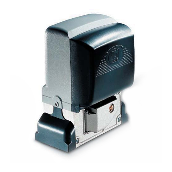
Привод CAME BX-78 разработан для автоматизации бытовых откакатных ворот, можно также использовать в кондоминиумах. Максимальная масса ворот 800 кг; для кондоминиумов 600 кг. Привод состоит из силуминового корпуса в котором расположен самоблокирующийся редуктор, и пластикого шасси на котором закреплены трансформатор и плата блока управления.
Отзывы по оборудованию и комментарии к материалу
![]()
CAME BX-78 Автоматика для откатных ворот — Инструкция по монтажу в формате pdf. Руководства по установке, настройке и эксплуатации оборудования.
Дата добавления: 05.07.2015
Размер файла: 4.1 Mb
Формат файла: pdf
Просмотров: 1072
Загрузок: 146
Дополнительная информация
ТЕХНИЧЕСКИЕ ХАРАКТЕРИСТИКИ
Вес: 15 кг
Мощность: 300Вт
Интенсивность использования: 30%
Скорость движения ворот: 10 м/мин (макс.)
Максимальный потребляемый ток: 2,6A
Напряжение питания системы:~230В, AC
Напряжение питания мотора:~230В, AC
Передаточное число: 1/33
Конденсатор: 12 мкФ
Максимальный вращающий момент: 24 Нм
Тепловая защита двигателя: 150° C
Усилие: 800 Н
Класс защиты: IP54
Отзывы и комментарии
Отзывы и комментарии к материалу «CAME BX-78 Автоматика для откатных ворот — Инструкция по монтажу».
-
Contents
-
Table of Contents
-
Troubleshooting
-
Bookmarks
Quick Links
AUTOMATION SYSTEMS FOR SLIDING GATES
BX-74 / BX-78
EN
English
Related Manuals for CAME BX-78
Summary of Contents for CAME BX-78
-
Page 1
AUTOMATION SYSTEMS FOR SLIDING GATES INSTALLATION MANUAL BX-74 / BX-78 English… -
Page 2
2 Conditions of use 2.1 Intended use The BX-74 motor is designed to operate residential sliding gates; while, the BX-78 may also be used in condominiums. Do not install or use unless as otherwise shown in this manual. 2.2 Limitations to use BX-74: max weight of the gate is 400 kg. -
Page 3
4.3 Description of parts 1 — Top cover 2 — Settings casing 3 — Control board support 4 — Endstop fins 5 — ZB74-78 electronic card 6 — Front cover to control panel 7 — Gearmotor release door 8 — Securing plate 9- Securing bolt 10- Securing screw plate 11- Nut… -
Page 4
5.2 Tools and materials Make sure you have all the tools and materials you will need for the installation at hand to work in total safety and compliance with the current standards and regulations. The following figure illustrates the minimum equipment needed by the installer. 5.3 Cable list and minimum thickness Connection Type of cable Length of cable 1 <… -
Page 5
5.5 Securing the plate and installing the assembly The following applications are only examples, as the space for installing the ratiomotor and accessories varies according to obstructions. It is thus up to the system installer to select the most suitable solution. — Dig a pit to the side of the gate (see measurements from diagram). -
Page 6
— To position the plate in relation to the rack please see the measurements on the diagram. Fill the form box with cement and wait for at least 24 hours for it to solidify. — Remove the form box, fi ll the pit around the cement block with soil. — Unbolt the nuts and washers from the bolts. -
Page 7
— Remove the cover from the gearmotor by loosening the side bolts, perforate the cable shafts using a screwdriver or a pair of scissors and position the gearmotor atop the plate. Careful! The electric cables must pass through the cable shafts. — Lift the gearmotor from the securing plate by about 5 to 10mm by using the threaded steel-levelling feet to allow any later adjustments between the pinion and the rack. -
Page 8
— Open and close the gate manually and register the pinion-to-rack distance using the threaded steel-levelling feet (for vertical adjusting) and the slotted holes (horizontal adjusting). This prevents the weight of the gate from bearing on the operator. Rack Rack Pinion Pinion Levelling feet… -
Page 9
5.6 Mounting the endstop fins Place the endstop fi ns onto the rack and secure them using a 3 mm Allen wrench. Their positioning limits the gate run. Note: the gate schould not slam against the mechanical stop, when opening or closing. Mechanical stop 5.7 Manually releasing the gearmotor — Insert the trilobed key into the lock, push it in and turn it clockwise .. -
Page 10: Control Board
6 Control board 6.1 General description Use 230V A.C. to power the electronic card using the L-N Apposite trimmers regulate: terminals, at a max 50/60Hz frequency. — The automatic closing’s running time; — The partial opening; Use 24V to power the command devices and accessories. Careful! The accessories cannot exceed 20W of overall power.
-
Page 11
6.3 Electrical connections Gearmotor, endstop and encoder Description of the standard electrical connections for left-hand installations Orange Black Orange White Closing microswitch Opening microswitch Condenser Modifications to the electrical connections for right-hand installations Orange Black Orange White Invert the gearmotor (U-V) and (FA-FC) endstop phases. Condenser Power supply for accessories Cable lug with bolt and washer for connecting to earth. -
Page 12
Warning devices Movement fl ashing light (Con- Open-gate status light tact range: 230V – 25W max) (contact range: 24V – 3W — Flashes during the gate’s max) opening and closing phases. — Signal that gate is open; turns off when gate is closed. -
Page 13
Safety devices DIR photocells «partial stop» (N.C.) contact — Input for EN 12978 standard-compliant safety devices such as photocells. Gate stops if moving and automatically shuts (if this functions has been selected). DIR photocells (N.C.) contact for «re-open during closing phase» — Input for EN 12978 standard-compliant safety devices such as photocells. -
Page 14
6.4 Function selector (dip-switch) DIP-SWITCH 4 DIP-SWITCH 10 1 2 3 4 1 2 3 4 5 6 7 8 9 1 0 DIP-SWITCH 10 1 ON — Automatic Closing — The automatic closing timer activates at the end of the opening gate run. The pre-set time is adjustable, and is in any case conditioned by the activation of any safety devices, and does not activate after a total safety “stop”… -
Page 15
6.6 Programming decelerations So as to fully meet the compliance requirements established by European Standards EN 12445 and EN 12453 on matters concerning maximum impact forces, BX-74/78 is set up for deceleration at 50 cm from the opening and closing endpoints. When installing all you need to do is program the gate operation as follows: Before proceeding, set all the DIP SWITCHES to OFF (10-way Dip Switches) a) — Set Dip Switch 4, 7, 8 and 9 to ON (10-way Dip Switch) and Dip Switch 3 e to OFF (4-way dip-switch, optical reader);… -
Page 16
6.8 Motor torque limiter To vary the motor torque, move the shown faston (the one with the black wire) to one of the 4 posi- tions: 1 min – 4 max. 7 Activating the radio command Antenna Possible output of the radio receiver’s Connect the antenna’s RG58 cable to second channel (N.O. -
Page 17
Radiofrequency card Insert the radio frequency card into the electronic card AFTER DISCONNECTING THE POWER (and disconnecting any batteries). N.B.: the electronic card picks up the radiofrequency card on when it is running on power AF Card Electronic card 5 6 7 8 9 1 0 1 2 3 4 1 2 3 4 Transmitters… -
Page 18
Memorisation — Keep the CH1 button on the electronic card pressed. The led fl ashes. CH1 = Channel for direct command to a function of the gearmotor’s card, (“open only/”open-close- invert” or ”open-stop- close-stop” vommand, 5 6 7 8 9 1 0 1 2 3 4 1 2 3 4 depending on the choice… -
Page 19
8 Connecting two joined motors with a single command 1) Coordinate the direction of travel of geared motors “A” and “B”, by modifying the rotation of motor “B” (see p. 11 geared motor- endstop connection) 2) Carry out the electrical connections on the geared-motor “A”… -
Page 20: Safety Instructions
9 Safety instructions Important safety instructions This product must only be employed for its originally intended use. Any other use is wrong and potentially dangerous. The manufacturer cannot be held liable for any damages resulting from wrongful, erroneous or negligent uses. Avoid working close to the hinges or other moving mechanical parts.
-
Page 21
10 Maintenance 10.1 Periodic maintenance Periodic maintenance to be carried out by the end-user is as follows: wipe clean the glass surface of the photocells; check that the safety devices work properly; remove any obstructions. We suggest checking the state of lubrication and tightness of the anchoring screws on the operator. -To check the efficiency of the safety devices, move an object in front of the photocells when gate is closing. -
Page 22
Periodic maintenance log for end-user (every 6 moths) Signature Date Notes 10.3 Extra-ordinary maintenance The following table serves to note down any extraordinary maintenance, repairs or improvements performed by specia- lised firms. N.B.: Any extraordinary maintenance must be performed by specialised technicians. Extra-ordinary maintenance log Installer’s stamp Operator name… -
Page 23
We ask you to keep protecting the environment, as CAME deems it to be one of the fundamental points of its market operations strategies, by simply following these brief guidelines when disposing: DISPOSING THE PACKING MATERIALS The packing components (cardboard, plastic, etc.) are solid urban waste and may be disposed of without any particular difficulty,… -
Page 24
(+33) 4 91 60 69 05 (+49) 71 5037830 (+49) 71 50378383 CAME Automatismos S.a. CAME Automatismos S.a. CAME Americas Automation Llc CAME Americas Automation Llc C/juan De Mariana, N. 17-local 1560 Sawgrass Corporate Pkwy, 4th Floor 28045 Madrid -…
This manual is also suitable for:
Bx-74
- Home
- Инструкции
- Автоматика для ворот
- CAME
- BX-78
![]() Автоматика для откатных ворот CAME BX-78 инструкция по монтажу на русском языке в формате pdf, размер файла 4.1 Mb. Используйте кнопки «Скачать инструкцию» или «Открыть в новом окне» (документ откроется в новом окне или вкладке браузера). Функция просмотра доступна при наличии плагина Adobe Acrobat в вашем браузере.
Автоматика для откатных ворот CAME BX-78 инструкция по монтажу на русском языке в формате pdf, размер файла 4.1 Mb. Используйте кнопки «Скачать инструкцию» или «Открыть в новом окне» (документ откроется в новом окне или вкладке браузера). Функция просмотра доступна при наличии плагина Adobe Acrobat в вашем браузере.
CAME BX-78 инструкция
Язык: Русский
Размер : 4.1 Mb
Формат файла: pdf
Добавлен: 09.06.2015
Руководство по установке
Предварительный просмотр
Информация, описание, технические характеристики изделия
Технические характеристики
Напряжение питания системы:~230В, AC
Напряжение питания мотора:~230В, AC
Максимальный потребляемый ток: 2,4A
Мощность: 300Вт
Максимальный вращающий момент: 32 Нм
Передаточное число: 1/33
Усилие: 800 Н
Скорость движения ворот: 10 м/мин (макс.)
Интенсивность использования: 30%
Класс защиты: IP54
Вес: 15 кг
Конденсатор: 20 мкФ
Тепловая защита двигателя: 150° C
Привод CAME BX-78 разработан для автоматизации бытовых откакатных ворот, можно также использовать в кондоминиумах. Максимальная масса ворот 800 кг; для кондоминиумов 600 кг. Привод состоит из силуминового корпуса в котором расположен самоблокирующийся редуктор, и пластикого шасси на котором закреплены трансформатор и плата блока управления.
Отзывы по оборудованию и комментарии к материалу
Здесь можно оставить свои отзывы по оборудованию «CAME BX-78 — Откатные ворота», а также написать комментарии к материалу.
![]()
CAME BX-78 Автоматика для откатных ворот — Инструкция по монтажу в формате pdf. Руководства по установке, настройке и эксплуатации оборудования.
Дата добавления: 05.07.2015
Размер файла: 4.1 Mb
Формат файла: pdf
Просмотров: 1018
Загрузок: 144
Дополнительная информация
ТЕХНИЧЕСКИЕ ХАРАКТЕРИСТИКИ
Вес: 15 кг
Мощность: 300Вт
Интенсивность использования: 30%
Скорость движения ворот: 10 м/мин (макс.)
Максимальный потребляемый ток: 2,6A
Напряжение питания системы:~230В, AC
Напряжение питания мотора:~230В, AC
Передаточное число: 1/33
Конденсатор: 12 мкФ
Максимальный вращающий момент: 24 Нм
Тепловая защита двигателя: 150° C
Усилие: 800 Н
Класс защиты: IP54
Отзывы и комментарии
Отзывы и комментарии к материалу «CAME BX-78 Автоматика для откатных ворот — Инструкция по монтажу».
В данном документе собраны все инструкции по приводам откатных ворот CAME. Здесь представлены инструкции только на приводы откатных ворот для удобства поиска нужных документов. Для просмотры других инструкций по автоматике ворот смотрите похожие статьи.
Похожие статьи

Инструкции автоматика CAME
В данном документе собраны все инструкции по автоматике ворот CAME, а также по всему дополнительному оборудованию. Инструкции на приводы откатных, распашных и гаражных ворот, системы безопасности (фот..

Инструкции блоки управления автоматики CAME
В данном документе собраны все инструкции по блокам управления автоматикой ворот CAME. Здесь представлены инструкции только для плат и блоков управления автоматикой ворот для удобства поиска нужных до..

Инструкции системы управления CAME
В данном документе собраны все инструкции по системам управления CAME. Здесь представлены инструкции по радиоуправлению, WI-Fi, GSM, системе CAME Connect и другим системам управления, в т.ч. проводным..

Инструкции системы безопасности CAME
В данном документе собраны все инструкции по системам безопасности CAME. Здесь представлены инструкции по фотоэлементам, светофорам, сигнальным лампам и другим системам безопасности. Для просмотры дру..

Инструкции аксессуары для автоматики CAME
В данном документе собраны все инструкции на аксессуары для автоматики ворот CAME. Здесь представлены инструкции только для дополнительных аксессуаров автоматики ворот для удобства поиска нужных докум..