
-
Contents
-
Table of Contents
-
Troubleshooting
-
Bookmarks
Quick Links
User’s
Manual
IM CA150E
CA150
HANDY CAL
IM CA150E
2nd Edition: Apr. 2007
Related Manuals for YOKOGAWA CA150
Summary of Contents for YOKOGAWA CA150
-
Page 1
User’s CA150 HANDY CAL Manual IM CA150E IM CA150E 2nd Edition: Apr. 2007… -
Page 2: Introduction
Introduction Thank you for purchasing the CA150 HANDY CAL. This User’s manual contains useful information regarding the instrument’s functions and operating procedures, as well as precautions that should be observed during use. To ensure proper use of the instrument, read the manual thoroughly before operating it.
-
Page 3: Checking The Contents Of The Package
Check that the model name given on the name plate on the back panel of the instrument matches the one on your order. • Model Model CA150 • Serial No. Should you need to contact the dealer from whom you purchased the instrument, have your unit’s serial number handy to give to the person.
-
Page 4: Optional Accessories
Checking the Contents of the Package Optional Accessories The following optional accessories are available. Upon receiving these optional accessories, make sure that all the items you ordered have been supplied and are undamaged. If you have any questions regarding optional accessories, or if you wish to place an order, contact the dealer from whom you purchased the instrument.
-
Page 5: Safety Precautions
When operating the instrument, strictly observe the precautions in this manual to ensure its correct and safe operation. If used other than as instructed in this manual, Yokogawa Meters & Instruments Corporation is not liable for any damage that may result.
-
Page 6
Some parts inside the instrument are extremely dangerous because they use a high voltage. When the instrument needs an internal inspection or calibration, contact Yokogawa Meters & Instruments Corporation or the dealer from whom you purchased the instrument. To use the AC adapter (optional) safely, be sure to comply with the following precautions. -
Page 7: Table Of Contents
Contents Introduction ………………1 Checking the Contents of the Package ……..2 Safety Precautions …………….4 1. Product Outline …………1-1 Product Outline …………..1-1 2. Names and Functions of Parts ……. 2-1 3. Before Starting Source or Measurement ….3-1 Usage Precautions …………. 3-1 Connecting a Power Supply ……….
-
Page 8
Contents Source Frequency and Pulse (PULSE) Signals ….. 4-15 4.7.1 Source a Continuous Pulse Train ……4-16 4.7.2 Source a Pulse Cycle ……….4-17 Divided Output (n/m) Function ……..4-18 Sweep Output Functions ……….4-19 4.9.1 Step Sweep Function ……….4-20 4.9.2 Linear Sweep Function ………. -
Page 9
Contents 8. Communication Function ……..8-1 Cable Connection and Interface Specifications ….8-1 Communication Command List ……..8-2 Detailed Description of Commands ……… 8-3 Error Code List …………..8-12 Table of Valid Communication Commands ….8-13 Status Byte Format …………8-15 Output Format of Printer Mode …….. -
Page 10: Product Outline
Product Outline 1.1 Product Outline Generation (SOURCE) Function Range DC Voltage (DCV) 100 mV, 1 V, 10 V, 30 V DC Current (DCA) 20 mA, 20 mA SINK, 4-20 mA Resistance ( ) , 5 k , 50 k Thermocouple (TC) K, E, J, T, N, L, U, R, S, B Resistance temperature detector (RTD) Pt100, JPt100 Frequency and pulse (PULSE)
-
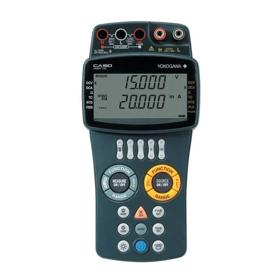
Page 11: Names And Functions Of Parts
Names and Functions of Parts Input terminals Output terminals Fuse holder (FUSE) LCD Screen Output value setting keys Measure Source keys keys Keys Battery holder RJ sensor connector RS232 connector AC adapter jack IM CA150E…
-
Page 12
Common Keys POWER Turns on/off the power. LIGHT Turns on/off the backlight of the LCD screen. (It turns off automatically if approximately 10 minutes elapse without a key being pressed.) SAVE Saves measurement values and setting values. LOAD Displays measurement values and loads setting values. ENTER Confirms the selected item or displays the temperature monitor. -
Page 13
SOURCE Keys Changes the source function. DCV → DCA → FUNCTION → TC → RTD → PULSE → (DCV) (The mark is lit for the selected function.) RANGE Changes the range for each function. SOURCE ON/OFF Turns on/off the source (setting value output). Selects/cancels divided output (n/m) mode. -
Page 14
LCD Screen Indicates the function selected with the FUNCTION key of MEASURE. Indicates the measurement value (top row: seven segments). MEASURE and the unit are also displayed. Indicates the function selected with the FUNCTION key of SOURCE. Indicates the source setting value (bottom row: seven segments). SOURCE and the unit are also displayed. -
Page 15
SOURCE: OFF lights when output is off or the protection circuit has been activated. ON lights when output is on. Indicates hold. Indicates that the 4-20 mA range is selected for the source. Flashes while communication data is being output. (When communication of the setting mode is set to printer mode.) Indicates that 24 V DC is being output for a loop test. -
Page 16
Digital Display of Alphanumeric Characters Since the LCD screen of the instrument has seven segments, alphanumeric characters are displayed as shown below. (Some of the characters are not used.) IM CA150E… -
Page 17: Before Starting Source Or Measurement
Some parts inside the instrument are extremely dangerous because they use a high voltage. When the instrument needs an internal inspection or calibration, contact Yokogawa Meters & Instruments Corporation or the dealer from whom you purchased the instrument. In the case of an abnormality If the instrument begins to emit smoke, give off an unusual odor, or show any other signs of an abnormality, immediately turn off the power switch.
-
Page 18
Chapter 3.1 Usage Precautions Operating Environment Use the instrument in locations that meet the following conditions: • Ambient temperature and humidity Ambient temperature: 0 to 40 C Ambient humidity: 20 to 80% RH (no condensation) Do not use the instrument in the following locations: •… -
Page 19: Connecting A Power Supply
Chapter 3.2 Connecting a Power Supply 3.2 Connecting a Power Supply In addition to AA-size alkaline batteries (six), the instrument can use two other types of power supply. • AA-size (LR6) alkaline batteries (six): 1.5 V • AC adapter (optional) •…
-
Page 20: Using An Ac Adapter
Chapter 3.2 Connecting a Power Supply 3.2.2 Using an AC Adapter Warning • Use the power cord supplied by Yokogawa Meters & Instruments Corporation for use with the instrument. • Make sure that the power supply voltage matches the ratedsupply voltage before connecting the power cord.
-
Page 21: Using An Nimh Battery Pack
AC adapter power cord from the outlet to avoid possible danger such as a short in the electric circuit or electrical shock. • Do not use any battery pack other than Yokogawa Meters and Instruments Corporation’s NiMH battery pack (model: 94015).
-
Page 22
Chapter 3.2 Connecting a Power Supply Installing the NiMH Battery Make sure that the power switch of the instrument is turned off and the lead cables and AC adapter are not connected. If alkaline batteries are in use, slide up the lock switch on the left side of the instrument and remove the alkaline battery holder before installing the NiMH battery. -
Page 23
AC adapter for charging. Warning Be sure to use the CA150 to charge the NiMH battery. Charge the NiMH battery in an environment with a temperature within the range of 10 to 35 C. Charging the battery at a temperature that is not in the range above may result in an insufficient charge, solution leakage, or heating up. -
Page 24: Fuse
Chapter 3.2 Connecting a Power Supply NiMH Battery Life The battery can be charged approximately 300 times. (This number varies depending on the operating environment.) The life of the battery is over when the low battery level indication appears only a short time after the battery is fully charged.
-
Page 25: Turning The Power On And Off
Chapter 3.3 Turning the Power On and Off 3.3 Turning the Power On and Off 3.3.1 Turning the Power On and Off When the power is off, press the POWER key to turn the power on. Press the POWER key again to turn the power off. Note Turn the power off before disconnecting the AC adapter from the power supply.
-
Page 26: Operating Environment
2000 m max. above sea level. Location Indoors Measurement Category (CAT.) The measurement category of the CA150 is I. Warning Do not use the CA150 for measurements in locations falling under Measure- ment Categories II, III, and IV. Measurement Category Measurement Category Description Remarks CAT.
-
Page 27
Note • For accurate source and measurement, operate the CA150 in the 23 ± 5 C tem- perature range and 55 ± 10% RH. • Condensation may occur if the CA150 is moved to another place where the ambient temperature and humidity are higher, or if the temperature changes rapidly. -
Page 28: Source
Source The instrument can source DC voltage, DC current (current sink), resistance, thermocouple, resistance temperature detector, and frequency/pulse signals. Warning To protect against the risk of electrical shock, do not apply a voltage of 30 V or more to the output terminals. Also ensure that the circuit-to-ground voltage does not exceed 30V.
-
Page 29: Connecting The Source Terminals
4.1 Connecting the Source Terminals 4.1 Connecting the Source Terminals Connect the supplied source lead cables (model: 98020) to the output terminals of the instrument. Connect the clips to the input terminals of the target device. Be sure to confirm the polarity to ensure the clips are correctly connected to the input terminals.
-
Page 30: Source Dc Voltage (Dcv) Signals
4.2 Source DC Voltage (DCV) Signals 4.2 Source DC Voltage (DCV) Signals Connect the terminals. Use the FUNCTION key on the SOURCE side to align the source mark with DCV. (DC voltage selection) Use the RANGE key to select a range. (100 mV, 1 V, 10 V, or 30 V) Use the output value setting keys to set each digit output value.
-
Page 31: Source Dc Current (Dca) Signals
4.3 Source DC Current (DCA) Signals 4.3 Source DC Current (DCA) Signals 4.3.1 Source DC Current Signals Connect the terminals. Use the FUNCTION key on the SOURCE side to align the source mark with DCA. (DC current selection) Use the RANGE key to select the 20 mA range. (Max. 22.000 mA) Use the output value setting keys to set each digit output value.
-
Page 32: Ma Function
4.3 Source DC Current (DCA) Signals 4.3.2 4-20 mA Function The source current can be increased or decreased in 4 mA steps. 4 mA steps Connect the terminals. Use the FUNCTION key on the SOURCE side to align the source mark with DCA.
-
Page 33: Ma Sink Function
H L mA MEASURE SOURCE AC or DC power supply CA150 Use the FUNCTION key on the SOURCE side to align the source mark with DCA. (DC current selection) Use the RANGE key to select the 20 mA range. (-22.000 mA to 22.000 Use the output value setting keys to set each digit output value.
-
Page 34
MEASURE SOURCE CA150 • If the equipment’s input inductance component is too large, connect a 200- resistor R and a 1- F capacitor C to the instrument’s outputs, as shown in the figure below. This setup makes it possible to connect an input having an inductance component of up to 3 H to the instrument. -
Page 35: Source Resistance ( ) Signals
0.01 F, the instrument may be unable to generate correct resistance values. Three-wire Connection Output Method Attach another black source lead cable (98020) to the output terminal L side. Black Device under calibration (Three-wire measuring equipment) SOURCE CA150 IM CA150E…
-
Page 36
4.4 Source Resistance ( ) Signals Connect the terminals. Use the FUNCTION key on the SOURCE side to align the source mark with . (Resistance selection) Use the RANGE key to select a range. (500 , 5 k , or 50 k ) Use the output value setting keys to set each digit output value. -
Page 37: Source Thermocouple (Tc) Signals
4.5 Source Thermocouple (TC) Signals 4.5 Source Thermocouple (TC) Signals 4.5.1 Source Thermocouple (TC) Signals Generate voltages (mV) corresponding to the following thermocouples. Set the temperature with ( C). This enables calibration of a thermometer. Thermocouple (TC) types: K, E, J, T, N, L, U, R, S, B (For the temperature range, refer to the specifications.) Connect the terminals.
-
Page 38: Using An External Rj Sensor
(generates) the compensated value. When calibrating a device with a built-in reference junction temperature compensator, connect an optional RJ sensor (model: B9108WA) to the instrument (RJ sensor connector). (RJON appears.) CA150 unit RJ sensor (B9108WA) Device under Device under calibration…
-
Page 39: Using The Built-In Rj Sensor
4.5 Source Thermocouple (TC) Signals 4.5.3 Using the Built-in RJ Sensor Although accurate temperature output (reference junction compensation) requires an external RJ sensor to be used, you can use the RJ sensor built into the instrument. The default setting (at shipment) is OFF. Set the built-in RJ sensor to ON (enable) in setting mode.
-
Page 40: Source Resistance Temperature Detector (Rtd) Signals
4.6 Source Resistance Temperature Detector (RTD) Signals 4.6 Source Resistance Temperature Detector (RTD) Signals Resistance Temperature Detector: Select from PT100 and JPT100. Temperature scale standard: Select from ITS-90 and IPTS-68. (The default setting: ITS-90) The temperature scale standard can be set in setting mode. Connect the terminals.
-
Page 41
4.6 Source Resistance Temperature Detector (RTD) Signals Setting the Temperature Scale Standard You can select from ITS-90 and IPTS-68 in setting mode. (The default setting: ITS-90) ITS-90: 1990 International Temperature Scale IPTS-68: 1968 International Practical Temperature Scale ENTER ENTER Simultaneously press the CLEAR and ENTER keys to switch to setting mode. -
Page 42: Source Frequency And Pulse (Pulse) Signals
4.7 Source Frequency and Pulse (PULSE) Signals 4.7 Source Frequency and Pulse (PULSE) Signals Amplitude voltage Frequency (setting value) (continuous) SOURCE Frequency (setting value) Amplitude voltage Pulse cycle (setting value) SOURCE n = pulse number Frequency (setting value) (setting value) PULSE SET Key When the generation of frequency and pulse signals is selected with FUNCTION of SOURCE, each press of the PULSE SET key toggles the mode…
-
Page 43: Source A Continuous Pulse Train
4.7 Source Frequency and Pulse (PULSE) Signals 4.7.1 Source a Continuous Pulse Train Connect the terminals. Use the FUNCTION key on the SOURCE side to select frequency and pulse (PULSE). ( PULSE appears.) Use the RANGE key to select a frequency setting mode. (Default setting: 100 Hz) (100 Hz, 1000 Hz, 10 kHz, 50 kHz, 1000 CPM) Use the…
-
Page 44: Source A Pulse Cycle
4.7 Source Frequency and Pulse (PULSE) Signals 4.7.2 Source a Pulse Cycle Connect the terminals. Use the FUNCTION key on the SOURCE side to select frequency and pulse (PULSE). ( PULSE appears.) Use the RANGE key to select a frequency setting mode. (Default setting: 100 Hz) (100 Hz, 1000 Hz, 10 kHz, 50 kHz, 1000 CPM) Use the…
-
Page 45: Divided Output (N/M) Function
4.8 Divided Output (n/m) Function 4.8 Divided Output (n/m) Function The divided output (n/m) function outputs a value n/m times the setpoint of a voltage, current, resistance, thermocouple or resistance temperature detector (RTD) signal. Output value = setting value n/m. Setting value n/m key Set the source value to output (FUNCTION, RANGE, Setting Value).
-
Page 46: Sweep Output Functions
4.9 Sweep Output Functions 4.9 Sweep Output Functions Three types of sweep output (generation) are available. Each press of the (SWEEP SET) key toggles the mode as shown below. Step Sweep → Linear Sweep → Program Sweep → Cancel When frequency or pulse (PULSE) is selected using FUNCTION, the sweep functions (step, linear, and program) cannot be used.
-
Page 47: Step Sweep Function
4.9 Sweep Output Functions 4.9.1 Step Sweep Function Set divided output (n/m) to be generated automatically as shown in the figure below. Source value indication Setting value Actual output Interval time setting value SOURCE ON key operation Press (ON) Set the source value to output (FUNCTION, RANGE, Setting Value). Press the SWEEP SET key to select Step Sweep.
-
Page 48
4.9 Sweep Output Functions Sweep Interval Time You can change the sweep interval time. The default setting (at shipment) is 5 seconds (FAST). Set 5 seconds (FAST) or 10 seconds (SLOW) in setting mode. When a sweep function is enabled, a setting mode cannot be selected. Disable the sweep function by pressing the SWEEP SET key and switch to the normal mode. -
Page 49: Linear Sweep Function
4.9 Sweep Output Functions 4.9.2 Linear Sweep Function Output can be varied in a continuous manner as shown in the figure below. SOURCE ON indication SOURCE OFF indication Flashing Flashing Setting value Source value indication Actual output Approx. 2 sec Approx.
-
Page 50
4.9 Sweep Output Functions Linear Sweep Time You can change the linear sweep time. The default setting (at shipment) is 16 seconds (FAST). Set 16 seconds (FAST) or 32 seconds (SLOW) in setting mode. When a sweep function is enabled, a setting mode cannot be selected. Disable the sweep function by pressing the SWEEP SET key and switch to the normal mode. -
Page 51: Program Sweep Function
4.9 Sweep Output Functions 4.9.3 Program Sweep Function Multiple setting values saved with the SAVE key can be output in order as shown in the figure below. Source Value Memory Number Function Range (Setting Value) 10 V 5.0000V 10 V 1.0000V 10 V 4.0000V…
-
Page 52
4.9 Sweep Output Functions Saving Source Values Set the source value to output (FUNCTION, RANGE, Setting Value). Press the SAVE key. (MEM No. appears.) Use the key to select the memory number. Press the ENTER key to confirm the selection. (MEM No. disappears.) Source value Program Sweep Press the SWEEP SET key three times to select Program Sweep. -
Page 53: Temperature Monitor Function
4.10 Temperature Monitor Function 4.10 Temperature Monitor Function The ambient temperature (temperature measured with the built-in RJ sensor) can be displayed when you are using a source function. A reading higher than the room temperature may be displayed because of a temperature rise within the instrument.
-
Page 54: Measurement
Measurement Warning • Turn off the power supply to the object to be tested before connecting it to the instrument. It is extremely dangerous to connect and disconnect measure- ment lead cables while power is being supplied to the object. •…
-
Page 55: Connecting The Measurement Terminals
5.1 Connecting the Measurement Terminals 5.1 Connecting the Measurement Terminals This shows the lead cable connections for when DCV, &ohm&, TC, RTD, or FREQ is selected with FUNCTION. For Measurement lead cables the connections when DCA or 24V (RD031) LOOP (DCA) is selected, refer to the Black next page.
-
Page 56
5.1 Connecting the Measurement Terminals DC Current (DCA) Black Measurement lead cables (RD031) Measurement input terminals 24V LOOP (DCA) Measurement lead Black cables (RD031) Measurement input terminals 3W ( , RTD) Terminal adapter (99022) Measurement input terminals IM CA150E… -
Page 57: Measuring Dc Voltage (Dcv)
5.2 Measuring DC Voltage (DCV) 5.2 Measuring DC Voltage (DCV) Measurement lead cables (RD031) Black Measurement input terminals Connect the terminals as shown in the figure above. Use the FUNCTION key on the MEASURE side to align the measurement mark with DCV. (DC voltage selection) Use the RANGE key to select a range.
-
Page 58: Measuring 24V Loop
H L mA 24V LOOP MEASURE CA150 Connect the terminals as shown in the figure above. Use the FUNCTION key on the MEASURE side to align the measurement mark with DCA. (DC current selection) Press the 24V LOOP key.
-
Page 59: Measuring Thermocouple (Tc)
5.4 Measuring Thermocouple (TC) 5.4 Measuring Thermocouple (TC) Thermocouple + leg — leg Terminal adapter (99022) Measurement input terminals Connect the terminals as shown in the figure above. Use the FUNCTION key on the MEASURE side to align the measurement mark with TC. (Thermocouple selection) Use the RANGE key to select a thermocouple type.
-
Page 60: Measuring Resistance ( )
5.5 Measuring Resistance ( ) 5.5 Measuring Resistance ( ) Two-wire method Three-wire method Terminal adapter (99022) Measurement lead Black cables (RD031) Measurement Measurement input terminals input terminals Terminal adapter (99022) Measurement input terminals Connect the terminals as shown in the figure above. Use the FUNCTION key on the MEASURE side to align the measurement mark with V.
-
Page 61: Measuring Resistance Temperature Detector (Rtd)
5.6 Measuring Resistance Temperature Detector (RTD) 5.6 Measuring Resistance Temperature Detector (RTD) Two-wire method Three-wire method Terminal adapter Measurement lead Black (99022) cables (RD031) Measurement Measurement input terminals input terminals Terminal adapter (99022) Measurement input terminals Connect the terminals as shown in the figure above. Use the FUNCTION key on the MEASURE side to align the measurement mark with RTD.
-
Page 62: Measuring Frequency (Freq) And Pulse
5.7 Measuring Frequency (FREQ) and Pulse 5.7 Measuring Frequency (FREQ) and Pulse 5.7.1 Measuring Frequency (FREQ) and Pulse Measurement lead cables Black (RD031) Measurement input terminals Connect the terminals as shown in the figure above. Use the FUNCTION key on the MEASURE side to align the measurement mark with FREQ.
-
Page 63: Measuring Contact Input
5.7 Measuring Frequency (FREQ) and Pulse 5.7.2 Measuring Contact Input The instrument can measure transistor contact on/off signals. Set contact input to ON in setting mode. The default setting (at shipment) is OFF. Simultaneously press the CLEAR and ENTER keys to switch to setting mode.
-
Page 64: Memory Function
Memory Function Two types of information are saved to memory: data memory items and setting memory items. (Data memory items and setting memory items are saved to separate memory areas.) Data Memory Items Information such as records of source values and measurement values and program sweep output data can be stored.
-
Page 65: Data Memory Items
6.1 Data Memory Items 6.1 Data Memory Items Memory number setting Memory operations IM CA150E…
-
Page 66: Saving
6.1 Data Memory Items 6.1.1 Saving Press the SAVE key when a source value or measurement value is displayed. MEM No. (memory number) appears. The next number after the largest used (saved) number appears. Use the key to change the memory number.
-
Page 67: Clearing Memory
6.1 Data Memory Items 6.1.3 Clearing Memory Follow the procedures below to clear (delete) saved data. Clearing Selected Memory Number Press the SAVE key. (Save mode) MEM No. (memory number) appears. Use the key to select a memory number. Press the CLEAR key. Clear confirmation indication The clear confirmation indication appears.
-
Page 68: Displaying (Confirming) Saved Data
6.1 Data Memory Items 6.1.4 Displaying (Confirming) Saved Data Follow the procedures below to display (confirm) saved data. Press the LOAD key. (Confirmation mode) MEM No. (memory number) and LOAD appear. Use the key to select a memory number. The save date and time appear. The saved data appears.
-
Page 69: Setting Memory Items
6.2 Setting Memory Items 6.2 Setting Memory Items In addition to normal mode (source/measurement) FUNCTION, RANGE, and source values (measurement values), the conditions of setting mode can also be saved. This enables you to load saved conditions and reproduce them (reflect the state) in source and measurement modes.
-
Page 70: Clearing Memory
6.2 Setting Memory Items 6.2.3 Clearing Memory Follow the procedure below to clear (delete) saved data. Clearing Selected Memory Number Simultaneously press the SAVE and ENTER keys. (Setting memory mode) MEM No. (memory number) appears. Use the key to select a memory number.
-
Page 71: Loading
6.2 Setting Memory Items 6.2.4 Loading Loading Simultaneously press the LOAD and ENTER keys. (Load mode) MEM No. (memory number) and LOAD appear. LOAD/SETUP appears. Use the key to select a memory number. If no data exists (empty) for the memory number, «——«…
-
Page 72: Setting Mode
Setting Mode In the normal mode, simultaneously press the CLEAR and ENTER keys to switch to setting mode. The following table shows the items that can be set in setting mode. (When the divided output (n/m) or a sweep function is enabled, a setting mode cannot be selected.) Level 1 Level 2: Detailed Items…
-
Page 73: Source
7.1 Source 7.1 Source (1) Interval Time This sets the interval time for step sweep and program sweep, as well as the sweep time for linear sweep. (These items cannot be set individually.) Default value: FAST Selection Interval Time Linear Sweep Time FAST 5 seconds 16 seconds…
-
Page 74: Measure
7.2 Measure 7.2 Measure (1) Averaging This enables (ON) or disables (OFF) the moving averaging process for measurement data. (default value: ON) If the reading (measurement value) fluctuates as a result of, for example, noise being included in the input signal, use the averaging function. Simultaneously press the CLEAR and ENTER keys to switch to setting mode.
-
Page 75: Configuration
7.3 Configuration 7.3 Configuration (1) Auto Power Off When auto power off is set, the whole LCD screen flashes if approximately 9 minutes 30 seconds elapse without a key being pressed. If no operation is performed within approximately 30 seconds after that, the power turns off automatically.
-
Page 76
7.3 Configuration (2) Communication You can select normal mode and printer mode for communication. (default value: Normal mode) Normal mode: Enables normal sending and receiving. Printer mode: Enables a source value and measurement value to be output to a printer at a specified interval* (0 to 3600 seconds). *:If the transfer interval of printer mode is set to 0 seconds, 1 data item is output each time the HOLD key is pressed. -
Page 77
7.3 Configuration (3) Date/Time You can set the date and time. (These settings are set to Japan time at the time of shipment.) Top row: Year (2 digits)/Month/Day Bottom row: Hour/Minute/Second Simultaneously press the CLEAR and ENTER keys to switch to setting mode. -
Page 78: Communication Function
Communication Function You can configure the instrument and confirm setting values and measurement values from a personal computer. Note You can use a communication cable to connect the instrument to an RS232 compliant serial port of a personal computer, etc. In printer mode, you can output source values and measurement values at pre- set intervals.
-
Page 79: Communication Command List
8.2 Communication Command List 8.2 Communication Command List ommand Description When When Normal Setting Sets and queries the source/SINK of the current (DCA) Queries whether the back light is on or off Starts charging the batteries when the AC adapter is connected Sets the source value during calibration Sets and queries the calibration item Sets and queries the calibration measurement function…
-
Page 80: Detailed Description Of Commands
8.3 Detailed Description of Commands 8.3 Detailed Description of Commands Setting and Control Command: Send command syntax Answer: Return data syntax of command (setting, control) with no response. When an error occurs, the same data as that of the error message ERRm (m = error number) displayed on the LCD is returned.
-
Page 81
8.3 Detailed Description of Commands Sets the source value during calibration Normal Setting Command = CD<Delimiter> → Answer = CD <Delimiter> During generation in calibration mode, sets the current output source values as the calibration values for the selected function, range, and scale (+FS/0). -
Page 82
8.3 Detailed Description of Commands Sets and queries the date and time Normal Setting Command = DTyyyymmddhhmmss<Delimiter> → Answer = DTyyyymmddhhmmss<Delimiter> Command = DT? (CrLf) → Return = yyyyy/mm/dd, hh:mm:ss<Delimiter> Parameter (default Value) yyyy: Year (2006) 4 byte, mm: Month (04) 2 byte, dd: Day (01) 2 byte hh: Hour (00) 2 byte, mm: Minute (00) 2 byte, ss: Second (00) 2 byte Setting (confirmation) of the 2 leftmost digits of the year is only possible for the communication function. -
Page 83
8.3 Detailed Description of Commands Sets and queries the mask of status byte Normal Setting Command = IMm<Delimiter> → Answer = IMm <Delimiter> Command = IM?<Delimiter> → Return = IMm <Delimiter> Performs detection or sets mask for each bit of status byte. If IM0 is set, all information bits are masked. -
Page 84
8.3 Detailed Description of Commands Sets and queries divided output (n/m) Normal Setting Command = NMm<Delimiter> → Answer = NMm <Delimiter> Command = NM?<Delimiter> → Return = NMm <Delimiter> Parameter m = 0: Off/1: On default Value of m = 0 (Off) Queries the battery charge state Normal Setting Command = OB<Delimiter>… -
Page 85
8.3 Detailed Description of Commands Requests sending of memory data Normal Setting Command = OMm<Delimiter> → Return = n <Delimiter> Query of memory data Parameter m = Memory Data Number (0 to 99) n = Date, Time, Measurement Values, Source Values, [PULSE Source Amplitude] <Delimiter>… -
Page 86
8.3 Detailed Description of Commands Outputs the setting information (conditions) Normal Setting Command = OS<Delimiter> → Return = Measure a<Delimiter> Function b<Delimiter> Range c<Delimiter> Source d<Delimiter> Function e<Delimiter> Range f<Delimiter> Data g<Delimiter> 24 V Output h<Delimiter> Light i<Delimiter> Charge j<Delimiter> Parameter a (Measure) = ON/OFF b (Measure Function) = DCV/DCA/OHM/TC/RTD/FREQ… -
Page 87
8.3 Detailed Description of Commands Sets and queries the source values Normal Setting Command = SDm<Delimiter> → Answer = SDm <Delimiter> Command = SD?<Delimiter> → Return = SDm <Delimiter> Parameter m = Source Values 100m V m = 0 to 110.000 mV m = 0 to 1.10000 V… -
Page 88
8.3 Detailed Description of Commands Starts/stops and queries source Normal Setting Command = SOm<Delimiter> → Answer = SOm <Delimiter> Command = SO?<Delimiter> → Return = SOm <Delimiter> Parameter m = 0: Stop/1: Start Sets and queries the source range Normal Setting Command = SRm<Delimiter>… -
Page 89: Error Code List
8.3 Detailed Description of Commands Increases the m (th) digit of the source value by 1 digit Normal Setting Command = UPm<Delimiter> → Answer = UP, OK <Delimiter> Parameter m = 1 to 5 (1: Least Significant Digit to 5: Most Significant Digit) Sets and queries start/stop of 24 V DC (LOOP) power supply Normal Setting Command = VOm<Delimiter>…
-
Page 90: Table Of Valid Communication Commands
8.5 Table of Valid Communication Commands 8.5 Table of Valid Communication Commands X: Invalid (restricted) Blank: Valid Linear Step Program Measure Normal Calibration Memory Setting Sweep Sweep Sweep ment Mode Mode Mode Mode Mode Mode Mode Mode ESC C ESC S When the temperature (TC, RTD) display function is selected for both source and measurement, the settings selected for the thermocouple and resistance temperature detector on the source side take priority.
-
Page 91
8.5 Table of Valid Communication Commands X: Invalid (restricted) Blank: Valid Linear Step Program Measure Normal Calibration Memory Setting Sweep Sweep Sweep ment Mode Mode Mode Mode Mode Mode Mode Mode When the temperature (TC, RTD) display function is selected for both source and measurement, the settings selected for the thermocouple and resistance temperature detector on the source side take priority. -
Page 92: Status Byte Format
8.6 Status Byte Format 8.6 Status Byte Format Description of the ESC S Command bit 7 bit 6 bit 5 bit 4 bit 3 bit 2 bit 1 bit 0 Output 24 V Power Overrange Syntax Output Measurem (Fixed) (Fixed) Error Supply Error…
-
Page 93: Output Format Of Printer Mode
8.7 Output Format of Printer Mode 8.7 Output Format of Printer Mode Source setting values and measurement values are output in printer mode (when a printer is connected). The output format is 29 characters per line. Example of Output When Source OFF and Measure OFF Source :OFF Measure :OFF…
-
Page 94: Calibration Mode
Calibration Mode To maintain high accuracy, it is recommended to calibrate the instrument once a year. This section describes the calibration procedure using the standard devices recommended in «Standard Device Selection.» (1) Standard Device Selection Source Function Function Standard Device Range Accuracy •…
-
Page 95: Calibration Of Source Functions
9.1 Calibration of Source Functions (Adjustment) (1) Calibration Points and Calibration Ranges Using the output setting value keys, adjust the output values so that the readings on the standard device (CA150 source values) match the calibration points shown below. Calibration Point Connection…
-
Page 96
500 ranges. (2) Connection Diagrams Digital Digital <1> DCV <2> DCA multimeter multimeter H (V) I (A) SOURCE SOURCE CA150 CA150 Digital <3> 20 mA SINK <4> &ohm&, RTD Digital multimeter multimeter I (A) H (V) SOURCE SOURCE Excitation… -
Page 97
9.1 Calibration of Source Functions (Adjustment) Use the SOURCE ON/OFF key to turn on the output. Use the output keys of the instrument to set the output value so that the value read by the multimeter connected to the instrument matches the zero point calibration value displayed on the top row. -
Page 98: Calibration Of Measurement Functions
9.2 Calibration of Measurement Functions (Adjustment) 9.2 Calibration of Measurement Functions (Adjustment) (1) Calibration Points and Calibration Ranges Enter the following calibration values from the standard device. Calibration Point Connection Function Range Condition Diagram ZERO Full Scale 500 mV 0 mV 500.00 mV <5>…
-
Page 99
<5> DCV <6> DCA DC voltage/current DC voltage/current standard standard MEASURE MEASURE CA150 CA150 <7> Reference Resistor MEASURE CA150 (3) Calibration Procedure Connect the instrument in accordance with the function and range to be calibrated. Refer to «(2) Connection Diagrams.»… -
Page 100
9.2 Calibration of Measurement Functions (Adjustment) Start +FS point calibration: The CAL and FS segments light, the input measurement value appears on the top row, and the + side full scale calibration value of the selected range appears on the bottom row. Input the calibration value displayed on the bottom row into the instrument from the standard generator. -
Page 101: Verification After Calibration
9.3 Verification after Calibration 9.3 Verification after Calibration After calibration is complete, verify that the instrument was calibrated correctly and that the calibration values were written to memory. Verification Procedure After calibration is complete, turn off the power. Turn the power back on and verify generation and measurement in normal mode (not calibration mode).
-
Page 102: Troubleshooting
Troubleshooting 10.1 Troubleshooting Checklist If the instrument will still not operate normally after checking the following items or if you notice a problem not listed, contact the dealer from whom you purchased the instrument. Problem Corrective Action Nothing appears on the LCD even When Running On Batteries when the power is turned on.
-
Page 103: Disposing The Product
With reference to the equipment types in the WEEE directive Annex 1, this product is classified as a “Monitoring and Control instrumentation” product. To return unwanted products within the EU area, contact your local Yokogawa Europe B. V. office. Do not dispose in domestic household waste.
-
Page 104: Specifications
Specifications Source Accuracy = (% of setting + V, mV, A, , C, CPM, H , kH ) at 23 5 C Setting Range Source Range Accuracy Remarks Resolution Output resistance: 100 mV 0 to 110.000 mV (0.02% +10 V) Approx.
-
Page 105
Setting Range Source Range Accuracy Remarks Resolution TC output *3 TC source accuracy (0.02% +1.2 C) does not include RJ However, 0 to 100 C 0 to 1768 C sensor accuracy. (0.02% +2 C) RJ Sensor Specification Measurement range: (0.02% +1.2 C) -10 to 50 C However, 0 to 100 C 0 to 1768 C… -
Page 106
Source during Charging Accuracy = (% of setting + V, mV, A, , C) at 23 5 C Setting Range Source Range Accuracy Remarks Resolution Output resistance: 100 mV 0 to 110.000 mV (0.04% +25 V) Approx. 6.5 source Maximum output: 10 mA 0 to 1.10000 V (0.035% +0.1 mV) -
Page 107
Measurement Accuracy = (% of reading + V, mV, A, , dgt, C) at 23 5 C Setting Range Source Range Accuracy Remarks Resolution 500 mV 0 to 500.000 mV (0.02% + 50 V) 10 V Input resistance: 1000 M or greater. Input resistance: 0 to 5.0000 V… -
Page 108
Measurement during Charging Accuracy = (% of reading + mV, A, , C) at 23 5 C Setting Range Source Range Accuracy Remarks Resolution 500 mV 0 to 500.000 mV (0.035% +0.1 mV) 10 V Input resistance: 1000 M or greater. Input resistance: 0 to 5.0000 V… -
Page 109
General and Common Specifications Source unit response time: 300 msec (time from start of voltage change to when voltage enters accuracy range) However, the time is 5 msec for 1 V, 10 V, (excitation current: 1 mA), and RTD (excitation current: 1 mA) ranges Source unit voltage limiter: Approximately 32 V Source unit current limiter:… -
Page 110
Battery life: When measurement is on and output is 5 V DC/10 k or greater: Approximately 8 hours for alkaline batteries and 10 hours for the dedicated NiMH battery Auto power off: Approximately 10 minutes (can be disabled) Insulation resistance: 50 M or more at 500 V DC between the input terminals and output terminals… -
Page 111
External Dimensions Unit: mm 11-8 IM CA150E… -
Page 112: Appendix 1 Using A Cold Junction Compensator
A cold junction compensator can be used when, for example, it is not possible to use an RJ sensor. The use of a cold junction compensator enables the reference junction to be 0 C. Cold junction compensator: Yokogawa T-MJ or the equivalent Connecting a Cold Junction Compensator Device under calibration…
-
Page 113: Appendix 2 Block Diagram
Appendix 2 Block Diagram Block Diagram App.2-1 IM CA150E…
-
Page 114: Appendix 3 Installing Ferrite Core
Appendix 3 Installing Ferrite Core Caution To comply with the EMC Directive, install the included ferrite cores on the lead cables as shown below (in a three-wire output system, the third source lead cable [black] must also be equipped with a ferrite core). Measurement lead cables Source lead cables RD031…
-
Page 115
YOKOGAWA EUROPE B. V. (THE NETHERLANDS) Phone: 31-334-64-1611 Facsimile: 31-334-64-1610 YOKOGAWA ENGINEERING ASIA PTE. LTD. (SINGAPORE) Phone: 65-6241-9933 Facsimile: 65-6241-2606 YOKOGAWA AMERICA DO SUL S. A. (BRAZIL) Phone: 55-11-5681-2400 Facsimile: 55-11-5681-1274 YOKOGAWA MEASURING INSTRUMENTS KOREA CORPORATION (KOREA) Phone: 82-2-551-0660 to -0664 Facsimile: 82-2-551-0665 YOKOGAWA AUSTRALIA PTY.
- Manuals
- Brands
- YOKOGAWA Manuals
- Test Equipment
- CA150
- User manual
-
Contents
-
Table of Contents
-
Troubleshooting
-
Bookmarks
Quick Links
User’s
Manual
IM CA150E
CA150
HANDY CAL
IM CA150E
7th Edition: Oct. 2017 (YMI)
Related Manuals for YOKOGAWA CA150
Summary of Contents for YOKOGAWA CA150
-
Page 1
User’s CA150 HANDY CAL Manual IM CA150E IM CA150E 7th Edition: Oct. 2017 (YMI) -
Page 2: Introduction
Introduction Thank you for purchasing the CA150 HANDY CAL. This User’s manual contains useful information regarding the instrument’s functions and operating procedures, as well as precautions that should be observed during use. Before using this product, thoroughly read this manual to understand how to use it properly.
-
Page 3: Checking The Contents Of The Package
Check that the model name given on the name plate on the back panel of the instrument matches the one on your order. • Model Model CA150 • Serial No. Should you need to contact the dealer from whom you purchased the instrument, have your unit’s serial number handy to give to the person.
-
Page 4
Checking the Contents of the Package Optional Accessories The following optional accessories are available. Upon receiving these optional accessories, make sure that all the items you ordered have been supplied and are undamaged. If you have any questions regarding optional accessories, or if you wish to place an order, contact the dealer from whom you purchased the instrument. -
Page 5: Safety Precautions
This manual is an essential part of the product; keep it a safe place for future reference. YOKOGAWA is by no means liable for any damage resulting from use of the instrument in contradiction to these cautionary notes. The following safety symbols are used on the instrument and in the manual: Danger! Handle with Care.
-
Page 6
Safety Precautions WARNING Indicates a hazard that may result in the loss of life or serious injury of the user unless the described instruction is abided by. CAUTION Indicates a hazard that may result in an injury to the user and/or physical damage to the product or other equipment unless the described instruction is abided by. -
Page 7
(model: 98020) without mistaking them. • Do Not Remove the Casing or Disassemble Only Yokogawa service personnel are authorized to remove the casing or disassemble or modify the instrument. Do not attempt to repair the instrument yourself, as doing so is extremely dangerous. -
Page 8
• To prevent the possibility electrical shock or fire, be sure to use the AC adapter and the power cord supplied by YOKOGAWA. Additionally, do not use the AC adapter and the power code supplied with this instrument with another instrument. -
Page 9: Précautions D’emploi
Ce manuel est une partie essentielle du produit ; le conserver dans un endroit sûr pour une référence ultérieure. YOKOGAWA ne saurait en aucun cas être déclaré responsable de tout dommage résultant d’une utilisation de l’instrument ne respectant pas ces mises en garde.
-
Page 10
Précautions d’emploi Avertissement Indique un danger. Attire l’attention sur une utilisation qui pourrait engendrer des accidents susceptibles de provoquer des blessures qui peuvent éventuel- lement s’avérer mortelles. Attention Indique un danger. Attire l’attention sur une utilisation qui pourrait engendrer une blessure personnelle et/ou être préjudiciable au produit. Remarque Indique les informations essentielles à… -
Page 11
L’instrument renferme des composants parcourus par des tensions élevées ce qui les rend extrêmement dangereux. Pour un contrôle interne ou un étalonnage de l’instrument, contacter YOKOGAWA ou le revendeur auprès duquel a été acheté l’instrument. IM CA150E… -
Page 12
à celle de la source d’alimentation. ・ Pour éviter tout choc électrique ou incendie, s’assurer d’utiliser l’adaptateur secteur et le cordon d’alimentation fournis par YOKOGAWA. Ne pas non plus utiliser l’adaptateur secteur et le cordon d’alimentation fournis avec cet instrument avec un autre instrument. -
Page 13
3.2.2 Utilisation d’un adaptateur secteur Avertissement • Pour éviter tout choc électrique ou incendie, s’assurer d’utiliser l’adaptateur secteur et le cordon d’alimentation fournis par YOKOGAWA. Ne pas non plus utiliser l’adaptateur secteur et le cordon d’alimentation fournis avec cet instrument avec un autre instrument. -
Page 14
Température de -20 à 45°C (emplacements avec humidité faible) Avertissement S’assurer d’utiliser le CA150 pour charger la batterie NiMH. Charger la batterie NiMH dans un environnement où la température se trouve entre 10 et 35°C. Charger la batterie à une température ne se trouvant pas dans la plage ci-dessus peut avoir pour conséquence une charge insuffisante,… -
Page 15
Lorsque l’instrument est sous tension, vérifier qu’il fonctionne normalement. 3.4 Environnement de fonctionnement Catégorie de mesure Avertissement Ne pas utiliser le CA150 pour les mesures dans les endroits qui appartiennent aux catégories de mesure II, III, et IV. 4. Source Avertissement Pour éviter tout risque de choc électrique, ne pas appliquer de tension de 30 V… -
Page 16
Précautions d’emploi Précaution pour brancher les bornes de sortie Attention Serrer l’écrou de la borne de sortie à la main. Ne pas utiliser d’outils ou d’objets similaires. Serrer l’écrou avec un outil ou objet similaire pourrait endommager la borne, et causer le dysfonctionne- ment de la production normale. -
Page 17
Précautions d’emploi 5. Mesure Avertissement • Mettre l’objet à tester hors tension avant de le brancher à l’instrument. Il est très dangereux de brancher et débrancher des câbles de dérivation de mesure pendant qu’un objet est sous tension. • Il est extrêmement dangereux de brancher de manière incorrecte la borne d’entrée de tension H et la borne d’entrée de courant mA. -
Page 18
Précautions d’emploi 9.1 Étalonnage des fonctions sources (ajustement) Attention • À propos de la configuration de décalage interne de résistance (500 Ω) *: Lors de l’étalonnage du point zéro, s’assurer que la tension entre les bornes H et L est d’environ ±20 µV (±0,02 mV). Si la valeur est dépassée, l’instrument doit être réparé… -
Page 19: Table Of Contents
Contents Introduction ……… 1 Checking the Contents of the Package .
-
Page 20
Contents Source Frequency and Pulse (PULSE) Signals ..4-15 4.7.1 Source a Continuous Pulse Train ….4-16 4.7.2 Source a Pulse Cycle . -
Page 21
Contents 7. Setting Mode ……..7-1 Source . -
Page 22: Product Outline
Product Outline 1.1 Product Outline Generation (SOURCE) Function Range DC Voltage (DCV) 100 mV, 1 V, 10 V, 30 V DC Current (DCA) 20 mA, 20 mA SINK, 4-20 mA Resistance (Ω) 500 Ω, 5 kΩ, 50 kΩ Thermocouple (TC) K, E, J, T, N, L, U, R, S, B Resistance temperature detector (RTD) Pt100, JPt100 Frequency and pulse (PULSE)
-
Page 23: Names And Functions Of Parts
Names and Functions of Parts Input terminals Output terminals Fuse holder (FUSE) LCD Screen Output value setting keys Measure Source keys keys Keys Battery holder RJ sensor connector RS232 connector AC adapter jack IM CA150E…
-
Page 24
2. Names and Functions of Parts Common Keys POWER Turns on/off the power. LIGHT Turns on/off the backlight of the LCD screen. (It turns off automatically if approximately 10 minutes elapse without a key being pressed.) SAVE Saves measurement values and setting values. LOAD Displays measurement values and loads setting values. -
Page 25
2. Names and Functions of Parts SOURCE Keys FUNCTION Changes the source function. DCV → DCA → Ω → TC → RTD → PULSE → (DCV) (The mark is lit for the selected function.) RANGE Changes the range for each function. SOURCE ON/OFF Turns on/off the source (setting value output). -
Page 26
2. Names and Functions of Parts LCD Screen Indicates the function selected with the FUNCTION key of MEASURE. Indicates the measurement value (top row: seven segments). MEASURE and the unit are also displayed. Indicates the function selected with the FUNCTION key of SOURCE. Indicates the source setting value (bottom row: seven segments). -
Page 27
2. Names and Functions of Parts SOURCE: OFF lights when output is off or the protection circuit has been activated. ON lights when output is on. Indicates hold. Indicates that the 4-20 mA range is selected for the source. Flashes while communication data is being output. (When communication of the setting mode is set to printer mode.) Indicates that 24 V DC is being output for a loop test. -
Page 28
2. Names and Functions of Parts Digital Display of Alphanumeric Characters Since the LCD screen of the instrument has seven segments, alphanumeric characters are displayed as shown below. (Some of the characters are not used.) IM CA150E… -
Page 29: Before Starting Source Or Measurement
Some parts inside the instrument are extremely dangerous because they use a high voltage. When the instrument needs an internal inspection or calibration, contact YOKOGAWA or the dealer from whom you purchased the instrument. • In the case of an abnormality…
-
Page 30
3.1 Usage Precautions Operating Environment Use the instrument in locations that meet the following conditions: • Ambient temperature and humidity Ambient temperature: 0 to 40°C Ambient humidity: 20 to 80% RH (no condensation) • Indoors Do not use the instrument in the following locations: •… -
Page 31: Connecting A Power Supply
3.2 Connecting a Power Supply 3.2 Connecting a Power Supply In addition to AA-size alkaline batteries (six), the instrument can use two other types of power supply. • AA-size (LR6) alkaline batteries (six): 1.5 V • AC adapter (optional) • NiMH (nickel hydrogen) battery (optional): Model: 94015 3.2.1 Using Alkaline Batteries Installing and Replacing Batteries…
-
Page 32: Using An Ac Adapter
WARNING • To prevent the possibility electrical shock or fire, be sure to use the AC adapter and the power cord supplied by YOKOGAWA. Additionally, do not use the AC adapter and the power code supplied with this instrument with another instrument.
-
Page 33: Using An Nimh Battery Pack
• Do not use any battery pack other than YOKOGAWA’s NiMH battery pack (model: 94015). • Do not leave the NiMH battery pack in strong direct sunlight, inside a vehicle under the hot sun, or near a fire, otherwise it may result in a solution leakage or deterioration in the performance and/or life.
-
Page 34
3.2 Connecting a Power Supply Installing the NiMH Battery Make sure that the power switch of the instrument is turned off and the lead cables and AC adapter are not connected. If alkaline batteries are in use, slide up the lock switch on the left side of the instrument and remove the alkaline battery holder before installing the NiMH battery. -
Page 35
Use the instrument and AC adapter for charging. WARNING Be sure to use the CA150 to charge the NiMH battery. Charge the NiMH battery in an environment with a temperature within the range of 10 to 35°C. Charging the battery at a temperature that is not in the range above may result in an insufficient charge, solution leakage, or heating up. -
Page 36: Fuse
3.2 Connecting a Power Supply • NiMH Battery Life The battery can be charged approximately 300 times. (This number varies depending on the operating environment.) The life of the battery is over when the low battery level indication appears only a short time after the battery is fully charged. In such a case, replace the NiMH battery pack with a new one.
-
Page 37: Turning The Power On And Off
3.3 Turning the Power On and Off 3.3 Turning the Power On and Off 3.3.1 Turning the Power On and Off When the power is off, press the POWER key to turn the power on. Press the POWER key again to turn the power off. Pressing the POWER key after the power is turned off does not turn the power on for approximately two seconds.
-
Page 38: Turning The Backlight On And Off
3.3 Turning the Power On and Off 3.3.3 Turning the Backlight On and Off The backlight of the LCD screen can be turned on. This makes it easy to see the screen when working in dark places. Press the LIGHT key to turn the backlight on. Press the LIGHT key again to turn the backlight off.
-
Page 39: Operating Environment
2000 m or less Indoors Measurement Category The CA150 is designed for measurement category O (Other). WARNING Do not use the CA150 for measurements in locations that fall under measurement categories II, III, and IV. Measurement Category Measurement Description Remarks…
-
Page 40
However, a temporary electrical conduction may occur depending on the concentration. NOTE • For accurate source and measurement, operate the CA150 in the 23 ± 5°C temperature range and 55 ± 10% RH. • Condensation may occur if the CA150 is moved to another place where the ambient temperature and humidity are higher, or if the temperature changes rapidly. -
Page 41: Source
Source The instrument can source DC voltage, DC current (current sink), resistance, thermocouple, resistance temperature detector, and frequency/pulse signals. WARNING To protect against the risk of electrical shock, do not apply a voltage of 30 V or more to the output terminals. Also ensure that the circuit-to-ground voltage does not exceed 30V.
-
Page 42: Connecting The Source Terminals
4.1 Connecting the Source Terminals 4.1 Connecting the Source Terminals Connect the supplied source lead cables (model: 98020) to the output terminals of the instrument. Connect the clips to the input terminals of the target device. Be sure to confirm the polarity to ensure the clips are correctly connected to the input terminals.
-
Page 43: Source Dc Voltage (Dcv) Signals
4.2 Source DC Voltage (DCV) Signals 4.2 Source DC Voltage (DCV) Signals Connect the terminals. Use the FUNCTION key on the SOURCE side to align source mark with DCV. (DC voltage selection) Use the RANGE key to select a range. (100 mV, 1 V, 10 V, or 30 V) Use the ▲…
-
Page 44: Source Dc Current (Dca) Signals
4.3 Source DC Current (DCA) Signals 4.3 Source DC Current (DCA) Signals 4.3.1 Source DC Current Signals Connect the terminals. Use the FUNCTION key on the SOURCE side to align source mark with DCA. (DC current selection) Use the RANGE key to select the 20 mA range. (Max. 22.000 mA) Use the ▲…
-
Page 45: Ma Function
4.3 Source DC Current (DCA) Signals 4.3.2 4-20 mA Function The source current can be increased or decreased in 4 mA steps. 4 mA steps Connect the terminals. Use the FUNCTION key on the SOURCE side to align source mark with DCA. (DC current selection) Use the RANGE key to select the 4-20 mA range.
-
Page 46: Ma Sink Function
4-20 mA H L mA MEASURE SOURCE AC or DC CA150 power supply Use the FUNCTION key on the SOURCE side to align source mark with DCA. (DC current selection) Use the RANGE key to select the 20 mA range.
-
Page 47
Equipment such as a converter MEASURE SOURCE CA150 • If the equipment’s input inductance component is too large, connect a 200 Ω resistor R and a 1 µF capacitor C to the instrument’s outputs, as shown in the figure below. -
Page 48: Source Resistance (Ω) Signals
0.01 µF, the instrument may be unable to generate correct resistance values. Three-wire Connection Output Method Attach another black source lead cable (98020) to the output terminal L side. Black Device under calibration (Three-wire measuring equipment) SOURCE CA150 IM CA150E…
-
Page 49
4.4 Source Resistance (Ω) Signals Connect the terminals. Use the FUNCTION key on the SOURCE side to align source mark with Ω. (Resistance selection) Use the RANGE key to select a range. (500 Ω, 5 kΩ, or 50 kΩ) Use the ▲ ▼ output value setting keys to set each digit output value. Each ▲… -
Page 50: Source Thermocouple (Tc) Signals
4.5 Source Thermocouple (TC) Signals 4.5 Source Thermocouple (TC) Signals 4.5.1 Source Thermocouple (TC) Signals Generate voltages (mV) corresponding to the following thermocouples. Set the temperature with (°C). This enables calibration of a thermometer. Thermocouple (TC) types: K, E, J, T, N, L, U, R, S, B (For the temperature range, refer to the specifications.) Connect the terminals.
-
Page 51: Using An External Rj Sensor
The instrument outputs (generates) the compensated value. When calibrating a device with a built-in reference junction temperature compensator, connect an optional RJ sensor (model: B9108WA) to the instrument (RJ sensor connector). (RJON appears.) CA150 unit WARNING To prevent electrical shock, RJ sensor (B9108WA) be sure to use the dedicated R.J.Sensor B9108WA only.
-
Page 52: Using The Built-In Rj Sensor
4.5 Source Thermocouple (TC) Signals 4.5.3 Using the Built-in RJ Sensor Although accurate temperature output (reference junction compensation) requires an external RJ sensor to be used, you can use the RJ sensor built into the instrument. The default setting (at shipment) is OFF. Set the built-in RJ sensor to ON (enable) in setting mode.
-
Page 53: Source Resistance Temperature Detector (Rtd) Signals
4.6 Source Resistance Temperature Detector (RTD) Signals 4.6 Source Resistance Temperature Detector (RTD) Signals Resistance Temperature Detector: Select from PT100 and JPT100. Temperature scale standard: Select from ITS-90 and IPTS-68. (The default setting: ITS-90) The temperature scale standard can be set in setting mode. Connect the terminals.
-
Page 54
4.6 Source Resistance Temperature Detector (RTD) Signals Setting the Temperature Scale Standard You can select from ITS-90 and IPTS-68 in setting mode. (The default setting: ITS-90) ITS-90: 1990 International Temperature Scale IPTS-68: 1968 International Practical Temperature Scale ENTER ENTER Simultaneously press the CLEAR and ENTER keys to switch to setting mode. -
Page 55: Source Frequency And Pulse (Pulse) Signals
4.7 Source Frequency and Pulse (PULSE) Signals 4.7 Source Frequency and Pulse (PULSE) Signals Amplitude voltage Frequency (setting value) (continuous) SOURCE Frequency (setting value) Amplitude voltage Pulse cycle (setting value) SOURCE n = pulse number Frequency (setting value) (setting value) PULSE SET Key When the generation of frequency and pulse signals is selected with FUNCTION of SOURCE, each press of the PULSE SET key toggles…
-
Page 56: Source A Continuous Pulse Train
4.7 Source Frequency and Pulse (PULSE) Signals 4.7.1 Source a Continuous Pulse Train Connect the terminals. Use the FUNCTION key on the SOURCE side to select frequency and pulse (PULSE). ( PULSE appears.) Use the RANGE key to select a frequency setting mode. (Default setting: 100 Hz) (100 Hz, 1000 Hz, 10 kHz, 50 kHz, 1000 CPM) Use the ▲…
-
Page 57: Source A Pulse Cycle
4.7 Source Frequency and Pulse (PULSE) Signals 4.7.2 Source a Pulse Cycle Connect the terminals. Use the FUNCTION key on the SOURCE side to select frequency and pulse (PULSE). ( PULSE appears.) Use the RANGE key to select a frequency setting mode. (Default setting: 100 Hz) (100 Hz, 1000 Hz, 10 kHz, 50 kHz, 1000 CPM) Use the ▲…
-
Page 58: Divided Output (N/M) Function
4.8 Divided Output (n/m) Function 4.8 Divided Output (n/m) Function The divided output (n/m) function outputs a value n/m times the setpoint of a voltage, current, resistance, thermocouple or resistance temperature detector (RTD) signal. Output value = setting value × n/m. Setting value n/m key Set the source value to output (FUNCTION, RANGE, Setting Value).
-
Page 59: Sweep Output Functions
4.9 Sweep Output Functions 4.9 Sweep Output Functions Three types of sweep output (generation) are available. Each press of the (SWEEP SET) key toggles the mode as shown below. Step Sweep → Linear Sweep → Program Sweep → Cancel When frequency or pulse (PULSE) is selected using FUNCTION, the sweep functions (step, linear, and program) cannot be used.
-
Page 60: Step Sweep Function
4.9 Sweep Output Functions 4.9.1 Step Sweep Function Set divided output (n/m) to be generated automatically as shown in the figure below. Source value indication Setting value Actual output Interval time setting value SOURCE ON key operation Press (ON) Set the source value to output (FUNCTION, RANGE, Setting Value). Press the SWEEP SET key to select Step Sweep.
-
Page 61
4.9 Sweep Output Functions Sweep Interval Time You can change the sweep interval time. The default setting (at shipment) is 5 seconds (FAST). Set 5 seconds (FAST) or 10 seconds (SLOW) in setting mode. When a sweep function is enabled, a setting mode cannot be selected. Disable the sweep function by pressing the SWEEP SET key and switch to the normal mode. -
Page 62: Linear Sweep Function
4.9 Sweep Output Functions 4.9.2 Linear Sweep Function Output can be varied in a continuous manner as shown in the figure below. SOURCE ON indication SOURCE OFF indication Flashing Flashing Setting value Source value indication Actual output Approx. 2 sec Approx.
-
Page 63
4.9 Sweep Output Functions Linear Sweep Time You can change the linear sweep time. The default setting (at shipment) is 16 seconds (FAST). Set 16 seconds (FAST) or 32 seconds (SLOW) in setting mode. When a sweep function is enabled, a setting mode cannot be selected. Disable the sweep function by pressing the SWEEP SET key and switch to the normal mode. -
Page 64: Program Sweep Function
4.9 Sweep Output Functions 4.9.3 Program Sweep Function Multiple setting values saved with the SAVE key can be output in order as shown in the figure below. Source Value Memory Number Function Range (Setting Value) 10 V 5.0000V 10 V 1.0000V 10 V 4.0000V…
-
Page 65
4.9 Sweep Output Functions Saving Source Values Set the source value to output (FUNCTION, RANGE, Setting Value). Press the SAVE key. (MEM No. appears.) Use the ▲ ▼ key to select the memory number. Press the ENTER key to confirm the selection. (MEM No. -
Page 66: Temperature Monitor Function
4.10 Temperature Monitor Function 4.10 Temperature Monitor Function The ambient temperature (temperature measured with the built-in RJ sensor) can be displayed when you are using a source function. A reading higher than the room temperature may be displayed because of a temperature rise within the instrument.
-
Page 67: Measurement
Measurement WARNING • Turn off the power supply to the object to be tested before connecting it to the instrument. It is extremely dangerous to connect and disconnect measurement lead cables while power is being supplied to the object. • It is extremely dangerous to incorrectly connect the voltage input terminal H and the current input terminal mA.
-
Page 68: Connecting The Measurement Terminals
5.1 Connecting the Measurement Terminals 5.1 Connecting the Measurement Terminals This shows the lead cable connections for when DCV, &ohm&, TC, RTD, or FREQ is selected with FUNCTION. For Measurement lead cables the connections when DCA or 24V (RD031) LOOP (DCA) is selected, refer to the Black next page.
-
Page 69
5.1 Connecting the Measurement Terminals DC Current (DCA) Black Measurement lead cables (RD031) Measurement input terminals 24V LOOP (DCA) Measurement lead Black cables (RD031) Measurement input terminals 3W (Ω, RTD) Terminal adapter (99022) Measurement input terminals IM CA150E… -
Page 70: Measuring Dc Voltage (Dcv)
5.2 Measuring DC Voltage (DCV) 5.2 Measuring DC Voltage (DCV) Measurement lead cables Black (RD031) Measurement input terminals Connect the terminals as shown in the figure above. Use the FUNCTION key on the MEASURE side to align measurement mark with DCV. (DC voltage selection) Use the RANGE key to select a range.
-
Page 71: Measuring 24V Loop
24 V DC H L mA 24V LOOP MEASURE CA150 Connect the terminals as shown in the figure above. Use the FUNCTION key on the MEASURE side to align measurement mark with DCA. (DC current selection) Press the 24V LOOP key.
-
Page 72: Measuring Thermocouple (Tc)
5.4 Measuring Thermocouple (TC) 5.4 Measuring Thermocouple (TC) CAUTION When using the terminal adapter (model: 99022), tighten the knob by hand. Do not use a tool or the like. Tightening the knob using a tool or the like may damage the terminal, resulting in the disability of measurement. Before storing the instrument in the carrying case, remove the terminal adapter (model: 99022).
-
Page 73: Measuring Resistance (Ω)
5.5 Measuring Resistance (Ω) 5.5 Measuring Resistance (Ω) CAUTION When using the terminal adapter (model: 99022), tighten the knob by hand. Do not use a tool or the like. Tightening the knob using a tool or the like may damage the terminal, resulting in the disability of measurement. Before storing the instrument in the carrying case, remove the terminal adapter (model: 99022).
-
Page 74: Measuring Resistance Temperature Detector (Rtd)
5.6 Measuring Resistance Temperature Detector (RTD) 5.6 Measuring Resistance Temperature Detector (RTD) CAUTION When using the terminal adapter (model: 99022), tighten the knob by hand. Do not use a tool or the like. Tightening the knob using a tool or the like may damage the terminal, resulting in the disability of measurement.
-
Page 75: Measuring Frequency (Freq) And Pulse
5.7 Measuring Frequency (FREQ) and Pulse 5.7 Measuring Frequency (FREQ) and Pulse 5.7.1 Measuring Frequency (FREQ) and Pulse Measurement Black lead cables (RD031) Measurement input terminals Connect the terminals as shown in the figure above. Use the FUNCTION key on the MEASURE side to align measurement mark with FREQ.
-
Page 76: Measuring Contact Input
5.7 Measuring Frequency (FREQ) and Pulse 5.7.2 Measuring Contact Input The instrument can measure transistor contact on/off signals. Set contact input to ON in setting mode. The default setting (at shipment) is OFF. Simultaneously press the CLEAR and ENTER keys to switch to setting mode.
-
Page 77: App
Memory Function Two types of information are saved to memory: data memory items and setting memory items. (Data memory items and setting memory items are saved to separate memory areas.) Data Memory Items Information such as records of source values and measurement values and program sweep output data can be stored.
-
Page 78: Data Memory Items
6.1 Data Memory Items 6.1 Data Memory Items Memory number setting Memory operations IM CA150E…
-
Page 79: Saving
6.1 Data Memory Items 6.1.1 Saving Press the SAVE key when a source value or measurement value is displayed. MEM No. (memory number) appears. The next number after the largest used (saved) number appears. Use the ▲ ▼ key to change the memory number. Press the ENTER key.
-
Page 80: Clearing Memory
6.1 Data Memory Items 6.1.3 Clearing Memory Follow the procedures below to clear (delete) saved data. Clearing Selected Memory Number Press the SAVE key. (Save mode) MEM No. (memory number) appears. Use the ▲ ▼ key to select a memory number. Press the CLEAR key.
-
Page 81: Displaying (Confirming) Saved Data
6.1 Data Memory Items 6.1.4 Displaying (Confirming) Saved Data Follow the procedures below to display (confirm) saved data. Press the LOAD key. (Confirmation mode) MEM No. (memory number) and LOAD appear. Use the ▲ ▼ key to select a memory number. The save date and time appear.
-
Page 82: Setting Memory Items
6.2 Setting Memory Items 6.2 Setting Memory Items In addition to normal mode (source/measurement) FUNCTION, RANGE, and source values (measurement values), the conditions of setting mode can also be saved. This enables you to load saved conditions and reproduce them (reflect the state) in source and measurement modes.
-
Page 83: Replacing And Saving
6.2 Setting Memory Items 6.2.2 Replacing and Saving Follow the procedure below to replace saved data (a memory number). Simultaneously press the SAVE and ENTER keys. (Setting memory mode) MEM No. (memory number) appears. Use the ▲ ▼ key to select a memory number. Press the ENTER key.
-
Page 84: Clearing Memory
6.2 Setting Memory Items 6.2.3 Clearing Memory Follow the procedure below to clear (delete) saved data. Clearing Selected Memory Number Simultaneously press the SAVE and ENTER keys. (Setting memory mode) MEM No. (memory number) appears. Use the ▲ ▼ key to select a memory number. Press the CLEAR key.
-
Page 85: Loading
6.2 Setting Memory Items 6.2.4 Loading Loading Simultaneously press the LOAD and ENTER keys. (Load mode) MEM No. (memory number) and LOAD appear. LOAD/SETUP appears. Use the ▲ ▼ key to select a memory number. If no data exists (empty) for the memory number, «——» appears. The saved data (settings) appears.
-
Page 86: Setting Mode
Setting Mode In the normal mode, simultaneously press the CLEAR and ENTER keys to switch to setting mode. The following table shows the items that can be set in setting mode. (When the divided output (n/m) or a sweep function is enabled, a setting mode cannot be selected.) Level 1 Level 2: Detailed Items…
-
Page 87: Source
7.1 Source 7.1 Source (1) Interval Time This sets the interval time for step sweep and program sweep, as well as the sweep time for linear sweep. (These items cannot be set individually.) Default value: FAST Selection Interval Time Linear Sweep FAST 5 seconds 16 seconds…
-
Page 88: Measure
7.2 Measure 7.2 Measure (1) Averaging This enables (ON) or disables (OFF) the moving averaging process for measurement data. (default value: ON) If the reading (measurement value) fluctuates as a result of, for example, noise being included in the input signal, use the averaging function. Simultaneously press the CLEAR and ENTER keys to switch to setting mode.
-
Page 89: Configuration
7.3 Configuration 7.3 Configuration (1) Auto Power Off When auto power off is set, the whole LCD screen flashes if approximately 9 minutes 30 seconds elapse without a key being pressed. If no operation is performed within approximately 30 seconds after that, the power turns off automatically.
-
Page 90
7.3 Configuration (2) Communication You can select normal mode and printer mode for communication. (defaultvalue: Normal mode) Normal mode: Enables normal sending and receiving. Printer mode: Enables a source value and measurement value to be output to a printer at a specified interval* (0 to 3600 seconds). -
Page 91
7.3 Configuration (3) Date/Time You can set the date and time. (These settings are set to Japan time at the time of shipment.) Top row: Year (2 digits)/Month/Day Bottom row: Hour/Minute/Second Simultaneously press the CLEAR and ENTER keys to switch to setting mode. -
Page 92: Communication Function
Communication Function You can configure the instrument and confirm setting values and measurement values from a personal computer. You can use a communication cable to connect the instrument to an RS232 compliant serial port of a personal computer, etc. In printer mode, you can output source values and measurement values at preset intervals.
-
Page 93: Communication Command List
8.2 Communication Command List 8.2 Communication Command List When When ommand Description Normal Setting Sets and queries the source/SINK of the current (DCA) Queries whether the back light is on or off Starts charging the batteries when the AC adapter is connected Sets the source value during calibration Sets and queries the calibration item Sets and queries the calibration measurement function…
-
Page 94
8.2 Communication Command List When When ommand Description Normal Setting Queries the battery charge state Outputs the measurement values Outputs the error information Requests sending of memory data Queries whether an external RJ sensor is connected Outputs the setting information (conditions) Sets and queries display of PULSE (source) Sets and queries the source values Sets and queries the source function… -
Page 95: Detailed Description Of Commands
8.3 Detailed Description of Commands 8.3 Detailed Description of Commands Setting and Control Command: Send command syntax Answer: Return data syntax of command (setting, control) with no response. When an error occurs, the same data as that of the error message ERRm (m = error number) displayed on the LCD is returned.
-
Page 96
8.3 Detailed Description of Commands Sets and queries the source/SINK of the current (DCA) Normal Setting → ○ × Command = ASm<Delimiter> Answer = ASm <Delimiter> → Command = AS?<Delimiter> Return = ASm <Delimiter> Parameter m=0: Source (Generation)/1:SINK (Draw in) When the current source setting value is 0 mA and the measurement function is other than DCA, an error is returned. -
Page 97
8.3 Detailed Description of Commands Sets the source value during calibration Normal Setting → × ○ Command = CD<Delimiter> Answer = CD <Delimiter> During generation in calibration mode, sets the current output source values as the calibration values for the selected function, range, and scale (+FS/0). -
Page 98
8.3 Detailed Description of Commands Sets and queries the date and time Normal Setting → × ○ Command = DTyyyymmddhhmmss<Delimiter> Answer = DTyyyymmddhhmmss<Delimiter> → Command = DT? (CrLf) Return = yyyyy/mm/dd, hh:mm:ss<Delimiter> Parameter (default Value) yyyy: Year (2006) 4 byte, mm: Month (04) 2 byte, dd: Day (01) 2 byte hh: Hour (00) 2 byte, mm: Minute (00) 2 byte, ss: Second (00) 2 byte Setting (confirmation) of the 2 leftmost digits of the year is only possible for the communication function. -
Page 99
8.3 Detailed Description of Commands Sets and queries the mask of status byte Normal Setting → ○ ○ Command = IMm<Delimiter> Answer = IMm <Delimiter> → Command = IM?<Delimiter> Return = IMm <Delimiter> Performs detection or sets mask for each bit of status byte. If IM0 is set, all information bits are masked. -
Page 100
8.3 Detailed Description of Commands Sets and queries divided output (n/m) Normal Setting → ○ × Command = NMm<Delimiter> Answer = NMm <Delimiter> → Command = NM?<Delimiter> Return = NMm <Delimiter> Parameter m = 0: Off/1: On default Value of m = 0 (Off) Queries the battery charge state Normal Setting →… -
Page 101
8.3 Detailed Description of Commands Requests sending of memory data Normal Setting → ○ × Command = OMm<Delimiter> Return = n <Delimiter> Query of memory data Parameter m = Memory Data Number (0 to 99) n = Date, Time, Measurement Values, Source Values, [PULSE Source Amplitude] <Delimiter>… -
Page 102
8.3 Detailed Description of Commands Outputs the setting information (conditions) Normal Setting → ○ × Command = OS<Delimiter> Return = Measure a<Delimiter> Function b<Delimiter> Range c<Delimiter> Source d<Delimiter> Function e<Delimiter> Range f<Delimiter> Data g<Delimiter> 24 V Output h<Delimiter> Light i<Delimiter> Charge j<Delimiter>… -
Page 103
8.3 Detailed Description of Commands Sets and queries the source values Normal Setting → ○ × Command = SDm<Delimiter> Answer = SDm <Delimiter> → Command = SD?<Delimiter> Return = SDm <Delimiter> Parameter m = Source Values 100m V m = 0 to ±110.000 mV m = 0 to ±1.10000 V 10 V m = 0 to ±11.0000 V… -
Page 104
8.3 Detailed Description of Commands Starts/stops and queries source Normal Setting → ○ ○ Command = SOm<Delimiter> Answer = SOm <Delimiter> → Command = SO?<Delimiter> Return = SOm <Delimiter> Parameter m = 0: Stop/1: Start Sets and queries the source range Normal Setting →… -
Page 105: Error Code List
8.4 Error Code List Increases the m (th) digit of the source value by 1 digit Normal Setting → ○ ○ Command = UPm<Delimiter> Answer = UP, OK <Delimiter> Parameter m = 1 to 5 (1: Least Significant Digit to 5: Most Significant Digit) Sets and queries start/stop of 24 V DC (LOOP) power supply Normal Setting →…
-
Page 106: Table Of Valid Communication Commands
8.5 Table of Valid Communicatin Commands 8.5 Table of Valid Communication Commands Invalid (restricted) Blank: Valid Linear Step Program Measure Normal Calibration Memory Setting Sweep Sweep Sweep ment Mode Mode Mode Mode Mode Mode Mode Mode × × × × ×…
-
Page 107
8.5 Table of Valid Communicatin Commands Invalid (restricted) Blank: Valid Measure Linear Step Program Normal Calibration Memory Setting Sweep Sweep Sweep ment Mode Mode Mode Mode Mode Mode Mode Mode × × × × × × × × × × ×… -
Page 108: Status Byte Format
8.6 Status Byte Format 8.6 Status Byte Format Description of the ESC S Command bit 7 bit 6 bit 5 bit 4 bit 3 bit 2 bit 1 bit 0 Output 24 V Power Overrange Syntax Output Measurem (Fixed) (Fixed) Error Supply Error…
-
Page 109: Output Format Of Printer Mode
8.7 Output Format of Printer Mode 8.7 Output Format of Printer Mode Source setting values and measurement values are output in printer mode (when a printer is connected). The output format is 29 characters per line. Example of Output When Source OFF and Measure OFF Source: Measure: OFF When Source OFF and Measure ON…
-
Page 110: Calibration Mode
Calibration Mode To maintain high accuracy, it is recommended to calibrate the instrument once a year. This section describes the calibration procedure using the standard devices recommended in «Standard Device Selection.» (1) Standard Device Selection Source Function Function Standard Device Range Accuracy •…
-
Page 111: Calibration Of Source Functions (Adjustment)
9.1 Calibration of Source Functions (Adjustment) (1) Calibration Points and Calibration Ranges Using the ▲ ▼ output setting value keys, adjust the output values so that the readings on the standard device (CA150 source values) match the calibration points shown below. Calibration Point…
-
Page 112
500 Ω ranges. (2) Connection Diagrams Digital Digital <1> DCV <2> DCA multimeter multimeter H (V) I (A) SOURCE SOURCE CA150 CA150 Digital Digital <3> 20 mA SINK <4> Ω, RTD multimeter multimeter I (A) H (V) SOURCE SOURCE… -
Page 113
9.1 Calibration of Source Functions (Adjustment) Use the SOURCE ON/OFF key to turn on the output. Use the ▲ ▼ output keys of the instrument to set the output value so that the value read by the multimeter connected to the instrument matches the zero point calibration value displayed on the top row. -
Page 114: Calibration Of Measurement Functions
9.2 Calibration of Measurement Functions (Adjustment) 9.2 Calibration of Measurement Functions (Adjustment) (1) Calibration Points and Calibration Ranges Enter the following calibration values from the standard device. Calibration Point Connection Function Range Condition Diagram ZERO Full Scale 500 mV 0 mV 500.00 mV <5>…
-
Page 115
DC voltage/current DC voltage/current standard standard H L mA H L mA MEASURE MEASURE CA150 CA150 <7> Ω Reference Resistor H L mA MEASURE CA150 (3) Calibration Procedure Connect the instrument in accordance with the function and range to be calibrated. -
Page 116
9.2 Calibration of Measurement Functions (Adjustment) Start +FS point calibration: The CAL and FS segments light, the input measurement value appears on the top row, and the + side full scale calibration value of the selected range appears on the bottom row. Input the calibration value displayed on the bottom row into the instrument from the standard generator. -
Page 117: Verification After Calibration
9.3 Verification after Calibration 9.3 Verification after Calibration After calibration is complete, verify that the instrument was calibrated correctly and that the calibration values were written to memory. Verification Procedure After calibration is complete, turn off the power. Turn the power back on and verify generation and measurement in normal mode (not calibration mode).
-
Page 118: Troubleshooting
10. Troubleshooting 10.1 Troubleshooting Checklist If the instrument will still not operate normally after checking the following items or if you notice a problem not listed, contact the dealer from whom you purchased the instrument. Problem Corrective Action Nothing appears on the LCD even When Running On Batteries when the power is turned on.
-
Page 119: Specifications
11. Specifications Source Accuracy = ± (% of setting + µV, mV, µA, Ω, °C, CPM, Hz, kHz) at 23±5°C Setting Range Source Range Accuracy Remarks Resolution Output resistance: 100 mV 0 to ±110.000 mV ±(0.02% +10 µV) 1 µV Approx.
-
Page 120
11. Specifications Setting Accuracy Range Source Range Remarks Resolution TC output *3 TC source accuracy ±(0.02% +1.2 °C) does not include RJ However, 0 to 100 °C 0 to 1768 °C sensor accuracy. ±(0.02% +2 °C) RJ Sensor Specification Measurement range: ±(0.02% +1.2 °C) -10 to 50 °C However, 0 to 100 °C… -
Page 121
11. Specifications Source during Charging Accuracy = ± (% of setting + µV, mV, µA, Ω, °C) at 23±5°C Setting Range Source Range Accuracy Remarks Resolution Output resistance: 100 mV 0 to ±110.000 mV ±(0.04% +25 µV) 1 µV source Approx. -
Page 122
11. Specifications Measurement Accuracy = ± (% of reading + µV, mV, µA, Ω, dgt, °C) at 23±5°C Measurement Range Accuracy Resolution Remarks Range 500 mV 0 to ±500.000 mV ±(0.02% + 50 µV) 10 µV Input resistance: 1000 MΩ or greater. Input resistance: 0 to ±5.0000 V ±(0.02% + 0.5 mV) -
Page 123
11. Specifications Measurement during Charging Accuracy = ± (% of reading + mV, µA, Ω, °C) at 23±5°C Measurement Range Accuracy Remarks Resolution Range 500 mV 0 to ±500.000 mV ±(0.035% +0.1 mV) 10 µV Input resistance: 1000 MΩ or greater. Input resistance: 0 to ±5.0000 V ±(0.035% +1 mV) -
Page 124
11. Specifications General and Common Specifications Source unit response time: 300 msec (time from start of voltage change to when voltage enters accuracy range) However, the time is 5 msec for 1 V, 10 V, 500 Ω (excitation current: 1 mA), and RTD (excitation current: 1 mA) ranges Source unit voltage limiter: Approximately 32 V Source unit current limiter:… -
Page 125
11. Specifications Serial interface: RS232 Display: Segmented LCD Backlight: LED backlight, auto off after 10 minutes Warm-up time: Approximately 5 minutes Power supply: Six AA-size alkaline batteries Dedicated NiMH battery or dedicated AC adapter (optional) The charging time is approximately 6 hours. Battery life: When measurement is on and output is 5 V DC/10 kΩ… -
Page 126
11. Specifications Safety standards: EN 61010-1, EN 61010-2-030 Measurement category O (Other) Indoor use, altitude 2000 m or less, pollution degree 2 Power supply: Optional electrical supply (AC Adapter) 12V DC, 20W max. UL61010-1 CAN/CSA C22.2 No.61010-1 EMC standards: EN 61326-1 Class B, EN 61000-3-2, EN 61000-3-3, EN 55011 Class B, Group 1 EMC Regulatory Arrangement in Australia and New Zealand EN 55011 Class B, Group 1… -
Page 127
11. Specifications External Dimensions Unit: mm 11-9 IM CA150E… -
Page 128: Sales In Each Country Or Region
With reference to the equipment types in the WEEE directive, this product is classified as a «Monitoring and control instruments» product. When disposing products in the EU, contact your local Yokogawa Europe B.V. office. Do not dispose in domestic household waste. 12-1…
-
Page 129: How To Replace And Dispose The Batteries
Battery type: Lithium Battery 12.3 Authorized Representative in the EEA Yokogawa Europe B.V. is the authorized representative of Yokogawa Test & Measurement Corporation for this product in the EEA. (EEA: European Economic Area) To contact Yokogawa Europe B.V., see the separate list of worldwide contacts, PIM 113-01Z2.
-
Page 130: For The Pollution Control Of Electronic And Electrical Products Of The People’s Republic Of China
12.4 For the Pollution Control of Electronic and Electrical Products of the People’s Republic of China 12.4 For the Pollution Control of Electronic and Electrical Products of the People’s Republic of China They are applicable only in China. 产品中有害物质的名称及含量 有害物质 部件名称…
-
Page 131: Appendix 1 Using A Cold Junction Compensator
RJ sensor. The use of a cold junction compensator enables the reference junction to be 0°C. Cold junction compensator: YOKOGAWA T-MJ or the equivalent Connecting a Cold Junction Compensator Device under calibration (thermometer)
-
Page 132: Appendix 2 Block Diagram
Appendix 2 Block Diagram ■ Block Diagram App.2-1 IM CA150E…
-
Page 133: Appendix 3 Installing Ferrite Core
Appendix 3 Installing Ferrite Core CAUTION To comply with the EMC Directive, install the included ferrite cores on the lead cables as shown below (in a three-wire output system, the third source lead cable [black] must also be equipped with a ferrite core). Measurement lead cables Source lead cables RD031…
(Ocr-Read Summary of Contents of some pages of the YOKOGAWA CA150 Document (Main Content), UPD: 21 May 2023)
-
100, Communication Function 8-9 IM CA150E 1 2 3 4 5 6 7 8 9 10 11 12 App NM Normal SettingSets and queries divided output (n/m) ○ ×Command = NMm<Delimiter> → Answer = NMm <Delimiter> Command = NM?<Delimiter> → Return = NMm <Delimiter> Parameter m = 0: Off/1: On default Value of m = 0 (Off) OB Normal SettingQueries the battery charge state ○ ×Command = OB<Delimiter> → Return = m <Delimiter> Parameter m = 0: Off 1: On (Charging) A qu…
-
94, Communication Function 8-3 IM CA150E 1 2 3 4 5 6 7 8 9 10 11 12 App 8.2 Communication Command List C ommand Description When Normal When Setting OB Queries the battery charge state O X OD Outputs the measurement values O O OE Outputs the error information O O OM Requests sending of memory data O X OR Queries whether an external RJ sensor is connected O X OS Outputs the setting information (conditions) O X PU Sets and…
-
95, 8-4 IM CA150E 8.3 Detailed Description of Commands Setting and Control Command: Send command syntax Answer: Return data syntax of command (setting, control) with no response. When an error occurs, the same data as that of the error message ERRm (m = error number) displayed on the LCD is returned. Query Command: Send command syntax Return: Return data syntax of command (query) with response. …
-
70, 5-4 IM CA150E 5.2 Measuring DC Voltage (DCV) Measurement lead cables (RD031) Black Red Measurement input terminals 1 Connect the terminals as shown in the gure above. 2 Use the FUNCTION key on the MEASURE side to align the measurement mark with DCV. (DC voltage selection) 3 Use the RANGE key to select a range. (35 V, 5 V, or 500 mV) Set the range in accordance with the object to be measured. 4 The measurement val…
-
51, Source 4-11 IM CA150E 1 2 3 4 5 6 7 8 9 10 11 12 App 4.5.2 Using an External RJ Sensor Use an RJ sensor to measure (detect) the temperature of the device under calibration, and compensate the thermoelectric emf. The instrument outputs (generates) the compensated value. When calibrating a device with a built-in reference junction temperature compensator, connect an optional RJ sensor (model: B9108WA) to the instrument (RJ sensor connector). …
-
46, YOKOGAWA CA150 4-6 IM CA150E 4.3.3 20 mA SINK Function The SINK function allows you to use DC current (DCA) with the polarity set to — (minus). This allows drawing (SINK) the specied value of the current from an external voltage source (distributor, etc.) in the direction of the H terminal. Thus, you can use the instrument in a loop test, for example, as a simulator for two-wire transmitters. CAUTION Use the external…
-
99, 8-8 IM CA150E IM Normal SettingSets and queries the mask of status byte ○ ○ Command = IMm<Delimiter> → Answer = IMm <Delimiter> Command = IM?<Delimiter> → Return = IMm <Delimiter> Performs detection or sets mask for each bit of status byte. If IM0 is set, all information bits are masked. If IM63 is set, the current operating conditions are reflected for all information bits. (No mask)…
-
30, 3-2 IM CA150E Operating Environment Use the instrument in locations that meet the following conditions: • Ambient temperature and humidity Ambient temperature: 0 to 40°C Ambient humidity: 20 to 80% RH (no condensation) • Indoors Do not use the instrument in the following locations: • Outdoors • In direct sunlight or near heat sources • Where the instrument is exposed to water or other liquids • Where there is a lot of mechanical vibration • Near noise …
-
96, Communication Function 8-5 IM CA150E 1 2 3 4 5 6 7 8 9 10 11 12 App AS Normal SettingSets and queries the source/SINK of the current (DCA) ○ × Command = ASm<Delimiter> → Answer = ASm <Delimiter> Command = AS?<Delimiter> → Return = ASm <Delimiter> Parameter m=0: Source (Generation)/1:SINK (Draw in) When the current source setting value is 0 mA and the measurement function is other than DCA, an error is returned. BL No…
-
93, 8-2 IM CA150E 8.2 Communication Command List C ommand Description When Normal When Setting AS Sets and queries the source/SINK of the current (DCA) O X BL Queries whether the back light is on or off O X BT Starts charging the batteries when the AC adapter is connected O X CD Sets the source value during calibration X O CL Sets and queries the calibration item X O CMF Sets and queries the calibration measurement function X O CP Sets the calibration point X O CS…
-
45, Source 4-5 IM CA150E 1 2 3 4 5 6 7 8 9 10 11 12 App 4.3.2 4-20 mA Function The source current can be increased or decreased in 4 mA steps. 4 mA steps 1 Connect the terminals. 2 Use the FUNCTION key on the SOURCE side to align the source mark with DCA. (DC current selection) 3 Use the RANGE key to select the 4-20 mA range. (4-20 mA lights.) 4 Set the output value. Use the ▲ ▼ output value setting keys for the two leftmo…
-
41, YOKOGAWA CA150 Source 4-1 IM CA150E 1 2 3 4 5 6 7 8 9 10 11 12 App 4. Source The instrument can source DC voltage, DC current (current sink), resistance, thermocouple, resistance temperature detector, and frequency/pulse signals. WARNING To protect against the risk of electrical shock, do not apply a voltage of 30 V or more to the output terminals. Also ensure that the circuit-to-ground voltage does not exceed 30V. Be sure to use the supplied lead cables.…
-
52, 4-12 IM CA150E 4.5.3 Using the Built-in RJ Sensor Although accurate temperature output (reference junction compensation) requires an external RJ sensor to be used, you can use the RJ sensor built into the instrument. The default setting (at shipment) is OFF. Set the built-in RJ sensor to ON (enable) in setting mode. ENTER ENTER 1 Simultaneously press the CLEAR and ENTER keys to switch to setting mode. SEt appears o…
-
111, 9-2 IM CA150E 9.1 Calibration of Source Functions (Adjustment) (1) Calibration Points and Calibration Ranges Using the ▲ ▼ output setting value keys, adjust the output values so that the readings on the standard device (CA150 source values) match the calibration points shown below. DCA DCV Calibration Point ZERO 0 mV 0 V 0 V 0 V 0 mA 0 mA 0 mV* 0 mV* 0 mV 0 mV 0 m V Full Scale 100.000 mV 1.00000 V 10.0000 V 30.00 V 20.000 mA -20.000 mA 500.00 mV 2500.00 mV 500.00 mV 2500.00 mV…
-
121, Specications 11-3 IM CA150E 1 2 3 4 5 6 7 8 9 10 11 12 App 100 mV DCV source DCmA source mA SINK Resistance source RTD output TC output 1 V 10 V 30 V 20 mA 20 mA SINK 500 Ω 5 kΩ 50 kΩ PT 100 JPT 100 K E J N T L U 0 to ±110.000 mV 0 to ±1.10000 V 0 to ±11.0000 V 0 to ±30.00 V 0 to +22.000 µA 0 to -22.000 µA 0 to 550.00 Ω 0 to 5.5000 kΩ 0 to 55.000 kΩ — 200.0 to 850.0 °C — 200.0 to 500.0 °C -200.0 to 1372.0 �…
![]()
<< >> << >>
GS CA150-01
■
CA150
■
●
と機器からの出力信号の測定が1
●
0.02 % DCV
ります。
●
イープ機能の3
■
●
DC30 V 22 mA DC35 V 100 mA
● SINK
“SINK”
●
5ms
1V, 10V, 500Ω 1mA
1mA 5ms300ms
1mA5ms YTA
●
2
+
4-20mA
—
●
TC K E J T N L U R S B 10 RTD Pt100 JPt100
●
TC RJCB9108WA
|
H |
H |
||||
|
H L |
L |
H L |
L |
||
|
SOURCE |
SOURCE |
||||
|
CA150 |
RJ |
CA150 |
RJ |
||
GS CA150-01 2007.05 YMI

<< >> << >>
●
10 2 RTD3
●
1 Hz 50 kHz 1 Hz11 kHz
●
+0.1 V +11 V
●
設定可能
● CPM / CPH /
1 1
●
|
← (12V or 24V) |
+ |
||
|
→ |
|||
|
+ |
|||
ルス信号は不連続であるため「CPM/CPH1 1
● (n/m)
設定値のn/m %
●
mn m =
|
m |
||||
|
n |
3 |
3 |
||||||||||||||||
|
2 |
2 |
2 |
||||||||||||||||
|
1 |
1 |
|||||||||||||||||
|
OFF |
0 |
|||||||||||||||||
|
SOURCE ON |
||||||||||||||||||
|
ON |
●
|
SOURCE ON |
SOURCE OFF |
|||||
|
2 |
3 |
||||
|
OFF |
||
|
SOURCE ON |
||
|
ON |
●
|
FUNCTION |
RANGE |
|||
|
MEM No. |
||||
|
0 |
DCV |
10V |
5.0000V |
|
|
1 |
DCV |
10V |
1.0000V |
|
|
2 |
DCV |
10V |
4.0000V |
|
|
3 |
DCV |
10V |
2.0000V |
|
|
4 |
DCV |
10V |
3.0000V |
|
|
5 |
||||
|
99 |
SOURCE
ON
5V
0V
|
0 |
1 |
2 |
3 |
4 |
3 |
2 |
1 |
0 |
1 |
2 |
0
●
設定条件を保存できます。
●
RS232
|
All Rights Reserved. Copyright © 2007, Yokogawa Meters & Instruments Corporation |
GS CA150-01 2007.05.18-00 |

|
<< >> << >> |
|
|
● |
|
|
YTA110 Pt100 |
|
|
YTA110 |
YTA110 |
|
CA150 |
|
|
CA150 YTA |
|
|
YTA YTA |
||||||
|
Single input (YTA110) |
||||||
|
1 |
(A) |
1 |
(A) |
1 |
(A) |
|
|
(B) |
(A) |
|||||
|
2 |
2 |
2 |
||||
|
(B) |
(B) |
(B) |
||||
|
3 |
3 |
3 |
||||
|
(B) |
||||||
|
4 |
4 |
4 |
||||
|
5 |
5 |
5 |
||||
|
2 |
3 |
4 |
●
|
EJ |
|||
|
EJA |
|||
|
EJX |
|||
|
EJ110 |
||
|
EJ CA150 |
||
|
44—-20m |
のモニタが可能です。 ただし圧力の指示確認はマノメータで にて確認。
●
|
1 |
21 |
11 |
|
2 |
22 |
12 |
|
3 |
23 |
13 |
|
4 |
24 |
14 |
|
5 |
25 |
15 |
|
6 |
26 |
16 |
|
7 |
27 |
17 |
|
8 |
28 |
18 |
|
9 |
29 |
19 |
|
10 |
30 |
20 |
UT351
|
UT/UP |
||||
|
(TC) |
(RTD) |
(mV, V) |
||
|
12 |
11 |
A |
12 |
|
|
12 |
b |
|||
|
13 |
13 |
|||
|
13 |
B |
|||
|
All Rights Reserved. Copyright © 2007, Yokogawa Meters & Instruments Corporation |
GS CA150-01 2007.05.18-00 |

● DAQSTATION DX1000
|
DX1000 |
||
|
/ |
||
|
DX1000 |
||
|
1 12ch |
||
|
CA150 |
||
● YS SLCD
YS80
|
A |
2 |
1 |
|
B |
3 |
|
|
C |
4 |
5 |
|
D |
6 |
7 |
|
F |
8 |
9 |
|
H |
10 |
11 |
|
J |
12 |
13 |
|
K |
14 |
15 |
|
L |
16 |
17 |
|
M |
18 |
19 |
|
N |
20 |
21 |
YS80 SLCD
SLCD CA150
■YS80 SLCD
|
1 |
17 |
*1 |
|||||
|
2 |
18 |
||||||
|
(1 5 V DC) |
|||||||
|
3 |
19 |
||||||
|
4 |
20 |
||||||
|
(1 5 V DC) |
( ) |
||||||
|
5 |
21 |
||||||
|
6 |
A |
||||||
|
(1 5 V DC) |
*2 |
||||||
|
7 |
B |
||||||
|
(4 20 mA DC) |
|||||||
|
8 |
C |
||||||
|
(1 5 V DC) |
|||||||
|
9 |
D |
||||||
|
(1 5 V DC) |
|||||||
|
10 |
F |
||||||
|
11 |
H |
||||||
|
(1 5 V DC) |
|||||||
|
12 |
J |
||||||
|
13 |
(C A) M |
K |
|||||
|
14 |
L |
||||||
|
15 |
C (A M) |
M |
|||||
|
16 |
N |
( ) |
*1 SCCD
*2
|
All Rights Reserved. Copyright © 2007, Yokogawa Meters & Instruments Corporation |
GS CA150-01 2007.05.18-00 |
 Loading…
You can only view or download manuals with
Sign Up and get 5 for free
Upload your files to the site. You get 1 for each file you add
Get 1 for every time someone downloads your manual
Buy as many as you need
Table of Contents for YOKOGAWA CA150:
-
9-2 IM CA150E 9.1 Calibration of Source Functions (Adjustment) (1) Calibration Points and Calibration Ranges Using the ▲ ▼ output setting value keys, adjust the output values so that the readings on the standard device (CA150 source values) match the calibration points shown below. DCA DCV Calibration Point ZERO 0 mV 0 V 0 V 0 V 0 mA 0 mA 0 mV* 0 mV* 0
-
3-10 IM CA150E 3.3.3 Turning the Backlight On and Off The backlight of the LCD screen can be turned on. This makes it easy to see the screen when working in dark places. Press the LIGHT key to turn the backlight on. Press the LIGHT key again to turn the backlight off. NOTE The backlight turns off automatically if approximately 10 minutes elapse without a key being pressed. To continue using the backlight, press any key other than the POWER key. Using the backlight when the instrument is running on batteries reduces the lifespan of the batteries. 3.
-
Source 4-1 IM CA150E 1 2 3 4 5 6 7 8 9 10 11 12 App 4. Source The instrument can source DC voltage, DC current (current sink), resistance, thermocouple, resistance temperature detector, and frequency/pulse signals. WARNING To protect against the risk of electrical shock, do not apply a voltage of 30 V or more to the output terminals. Also ensure that the circuit-to-ground voltage does not exceed 30V. Be sure to use the supplied lead cables. CAUTION Do not apply any voltage to the output t
-
Memory Function 6-3 IM CA150E 1 2 3 4 5 6 7 8 9 10 11 12 App 6.1.1 Saving 1 Press the SAVE key when a source value or measurement value is displayed. MEM No. (memory number) appears. The next number after the largest used (saved) number appears. 2 Use the ▲ ▼ key to change the memory number. 3 Press the ENTER key. The data is saved and save mode is canceled. (To not save the data, press the SAVE key to cancel save mode.) Tip To conrm saved data, press the LOAD key. After pressing the LOAD key, use the ▲▼
-
Sales in Each Country or Region 12-1 IM CA150E 1 2 3 4 5 6 7 8 9 10 11 12 App 12. Sales in Each Country or Region 12.1 Disposing the Product Waste Electrical and Electronic Equipment (WEEE), Directive (This directive is valid only in the EU.) This product complies with the WEEE directive marking requirement. This marking indicates that you must not discard this electrical/electronic product in domestic household waste. Product Category With reference to the equipment types in the WEEE directive, this product is classied as a «Monitoring and control in
-
4-6 IM CA150E 4.3.3 20 mA SINK Function The SINK function allows you to use DC current (DCA) with the polarity set to — (minus). This allows drawing (SINK) the specied value of the current from an external voltage source (distributor, etc.) in the direction of the H terminal. Thus, you can use the instrument in a loop test, for example, as a simulator for two-wire transmitters. CAUTION Use the external pow
-
Setting Mode 7-5 IM CA150E 1 2 3 4 5 6 7 8 9 10 11 12 App 7.3 Conguration (2) Communication You can select normal mode and printer mode for communication. (defaultvalue: Normal mode) Normal mode: Enables normal sending and receiving. Printer mode: Enables a source value and measurement value to be output to a printer at a specied interval* (0 to 3600 seconds). *: If
-
Communication Function 8-5 IM CA150E 1 2 3 4 5 6 7 8 9 10 11 12 App AS Normal SettingSets and queries the source/SINK of the current (DCA) ○ × Command = ASm<Delimiter> → Answer = ASm <Delimiter> Command = AS?<Delimiter> → Return = ASm <Delimiter> Parameter m=0: Source (Generation)/1:SINK (Draw in) When the current source setting value is 0 mA and the measurement function is other than DCA, an error is retur
-
Source 4-25 IM CA150E 1 2 3 4 5 6 7 8 9 10 11 12 App 4.9 Sweep Output Functions Saving Source Values 1 Set the source value to output (FUNCTION, RANGE, Setting Value). 2 Press the SAVE key. (MEM No. appears.) 3 Use the ▲ ▼ key to select the memory number. 4 Press the ENTER key to conrm the selection. (MEM No. disappears.) Source value Program Sweep 1 Press the SWEEP SET key three times to select Program Sweep. Step Sweep → Linear Sweep → Program Sweep (SWEEP and MEM NO. appear.)
-
4-10 IM CA150E 4.5 Source Thermocouple (TC) Signals 4.5.1 Source Thermocouple (TC) Signals Generate voltages (mV) corresponding to the following thermocouples. Set the temperature with (°C). This enables calibration of a thermometer. Thermocouple (TC) types: K, E, J, T, N, L, U, R, S, B (For the temperature range, refer to the specications.) 1 Connect the terminals. 2 Use the FUNCTION key on the SOURCE side to align the source mark with TC. (Thermocouple selection) 3
-
Appendix App.3-1 IM CA150E 1 2 3 4 5 6 7 8 9 10 11 12 App Appendix 3 Installing Ferrite Core CAUTION To comply with the EMC Directive, install the included ferrite cores on the lead cables as shown below (in a three-wire output system, the third source lead cable [black] must also be equipped with a ferrite core). 50mm 50mm Ferrite core A1193MN Measurement lead cables RD031 Source lead cables 98020
-
Calibration Mode 9-3 IM CA150E 1 2 3 4 5 6 7 8 9 10 11 12 App 9.1 Calibration of Source Functions (Adjustment) Tip • You can select to calibrate just the functions and ranges that require calibration. (Be sure to perform both zero point and full scale (FS) calibration of the same range together.) • Calibration of thermocouple (TC) and resistance temperature detector (RTD) takes place at the same time as calibration of the100 mV and 500 Ω ranges. (2) Connecti
-
5 IM CA150E WARNING Indicates a hazard that may result in the loss of life or serious injury of the user unless the described instruction is abided by. CAUTION Indicates a hazard that may result in an injury to the user and/or physical damage to the product or other equipment unless the described instruction is abided by. NOTE Indicates information that is essential for handling the instrument or should be noted in order to familiarize yourself with the instrument’s operating proce- dures and/or functio
-
3-12 IM CA150E Pollution Degree The pollution degree of the CA150 in the operating environment is 2. Pollution Degree applies to the degree of adhesion of a solid, liquid, or gas which deteriorates withstand voltage or surface resistivity. Pollution Degree 2 applies to normal indoor atmospheres. Normally, only non-conductive pollution is emitted. However, a temporary electrical conduction may occur depending on the co
Questions, Opinions and Exploitation Impressions:
You can ask a question, express your opinion or share our experience of YOKOGAWA CA150 device using right now.