-
Contents
-
Table of Contents
-
Bookmarks
Quick Links
R
User’s Manual
Intelligent Electrical System Circuit Tester
Intelligent Electrical System Circuit Tester
BT280
Summary of Contents for Autool BT280
-
Page 1
User’s Manual Intelligent Electrical System Circuit Tester Intelligent Electrical System Circuit Tester BT280… -
Page 2: Table Of Contents
TABLE OF CONTENTS 1. About BT280………………2 Overview………………..3 Specifications and Parameters…………4 Packing List……………….. 4 Power Supply Connectio…………… 5 Key Button Operation…………….5 Circuit Breaker Protection…………..6 2. Working Mode………………7 Smart Test………………..7 Multimeter Mode………………8 Oscilloscope Mode…………….9 Relay Test………………..10…
-
Page 3
Safety Precautions and Warnings To prevent personal injury or damage to vehicles and / or the scan tool, read this user’s manual first carefully and observe the following safety precautions at a minimum whenever working on a vehicle: Always perform automotive testing in a safe Environment. Do not attempt to operate or observe the tool while driving a vehicle, Operating or observing te tool will cause driver distraction and could cause a fatal accident. -
Page 4: About Bt280
The bt280 is the newest generation intelligent Electrical System Cir- cuit Tester with 2.4 inch large size LCD screen display. It is dedicated to test all 9V-30V vehicle electrical systems. BT280 is Convenient, Fast and Intelligent ! Smart Test — Auto Detect Volts and Ohms Multimeter Mode(Voltage,Resistance,Diode,Open&Short,…
-
Page 5: Overview
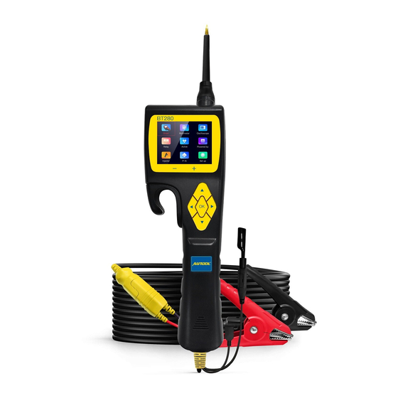
1.1 Overview ① Probe Tip — contact the circuit or component for testing. ② Front LED light- Used for lighting in dark working areas or when working at night. ③ Red/green LED indicator- Positive and Negative indicator light. ④ LCD screen- Display test results. ⑤ Key Button Operation- 5 Keys Navigating for fast operation.
-
Page 6: Specifications And Parameters
⑧ Minimum measuring voltage: 0.1V ⑨ Resistance measurement range: 1 ohm~200K ohm ⑩ Current measuring range: 0~18A Maximum continuous current: 18A 1.3 Packing List BT280 Unit with 6 meters test line Solid copper test probe tip Extension connection line Alligator battery clip Relay test line…
-
Page 7: Power Supply Connectio
1.4 Power Supply Connection The Probe is powered by the vehicle battery. Connect the RED clip to the positive pole of the battery, and the BLACK clip to the negative pole of the battery. The machine will automatically start to enter the working interface, The front LED light will illuminate the test area, which is conve- nient for operation in the dark area.
-
Page 8: Circuit Breaker Protection
* Do not use the BT280 probe to test the voltage of the household AC Power (such as 110V, 220V plug), , it may cause serious injury and property damage for improperly operation.
-
Page 9: Working Mode
Working Mode 2.Working Mode This probe adopts a 2.4-inch large color screen and 9-grid interface design, with clear display, simple operation and quick in use. You can select working mode through the navigation buttons and press OK to enter. 2.1 Smart Test The main test functions of this mode: voltage test , resistance test, Posi- tive/negative test.
-
Page 10: Multimeter Mode
As shown in the figure, “BATT” means that the battery supply voltage is 9.9V, and “VDC” is the current test DC voltage value 10.0V. 2.1.2 Resistance Test Result How to use: When the probe clip (auxiliary ground lead) is connected to an electrical circuit of resistance and the probe Tip is connected to the other end of the resistance, the probe will automatically enter into the resis- tance display mode and display the resistance values.
-
Page 11: Oscilloscope Mode
2.2.1 Functions Display The bottom of the interface is the functional area from left to right are: DC voltage (VDC), resistance (OHM), diode/continuity test (DIO), current (AMP), frequency (HZ). 2.2.2 How to use: Press the “right » button to select the test mode. Press “Left » Button to exit.
-
Page 12: Relay Test
“DIV» voltage per grid (test range 1V-49V) Press up and down keys to adjust the voltage value) “Time» time parameter “HZ» Display test frequency *Press and hold left key to Exit this working mode 2.4 Relay Test Instructions: The “VCC” at the top of this interface displays the power supply voltage value .
-
Page 13
Relay wiring connection as figure below: (5-terminal relay) (Test Results) (4-terminal relay) For example, Test a 5-terminal relay 1) Connect the relay test wire to probe . 2) Connect the black wire to the relay terminal 30#. 3) Connect the green wire to the relay terminal 87A#. 4) Connect the red wire to the relay terminal 87#. -
Page 14: Component Activation
2.5 Component Activation Warning: The activation mode is only designed for supply powers or ground, and cannot be used for any sensitive electronics equipment (such as ECU, sensor module), otherwise there is a risk of burning out compo- nents. Warning: Do not perform any tests on any ECU module ,SRS (air bag) system before the system is completely disabled or unplugged.
-
Page 15
2.5.2 Activation Type: “MOMENT” Mode: Press “Right” button to select the activation mode to MOMENT mode. Off Press and hold the “UP” /” Down” button to perform the power supply , Release “UP” Press Release /” Down” button to stop. “LATCH”… -
Page 16: 0-5V Power Supply
2.6 0-5V Power Supply The 0-5V power supply function is useful when checking the wiring to the ECU/ECM. After you check the sensor with a Multimeter , if there is still a problem, you can simulate the voltage output by the sensor to verify the wiring to the ECU.
-
Page 17: Fuel Injector Test
2.7 Injector Test The Probe outputs different pulse signals to the injector, and check the injector spraying status. This function can help diagnose injector conditions. It can work with any fuel pressure tester. 2.7.1 Signal output mode: MODE 1: Press «OK» button to activate Probe outputs 1 Pulse. Pulse width is 250ms MODE 2: Press «OK»…
-
Page 18: Positive/Negative Test
2.7.2 Test Fuel Injector: 1). Turn off the Vehicle’ s engine 2). Connect the BLACK clip to the negative terminal of the battery and the RED clip to the positive terminal of the battery. 3). Unplug the connector from the fuel injector, connect the Probe auxiliary ground lead to the negative side of the injector,And Probe Tip to the positive side of the injector.
-
Page 19: Setting
2.8.2 Positive Interface: After detected Positive signal , it will display voltage values and Positive (+) symbol. 2.8.3 Negative Interface: After detected Negative signal , it will display Ground icon and Negative (+) symbol. 2.9 Setting — 17 -…
-
Page 20: Online Update
From setting interface, you can set , Sound, Language, update, Screen, Use “UP” and “DOWN” button to select , press “OK ” button to Change parameters. Press “LEFT” button to save and exit. 2.10 Online Update 1. After in setting interface, Select Update menu to enter into Update mode.
-
Page 21: Test Applications
Test Applications 3.Test Applications 3.1 Continuity Testing When the Probe is in the “Multimeter mode “ Select Resistance test func- tion, Use the Probe Tip with chassis ground of the vehicle or auxiliary ground lead, Continuity can be tested on wires and components attached or disconnected from the vehicles electrical system.
-
Page 22: Signal Circuit Test
There is another way to verify the continuity of the connection to the ground or battery, While in Component Activation mode, You can supply power to the electrical system . if the circuit breaker trips, it means that this connections is a good connection with low resistance. Warning: Do not perform any tests on any ECU module ,SRS (air bag) system before the system is completely disabled or unplugged.
-
Page 23: Activating Components In You Hand
* If the Waveform reading is abnormal, There should be a problem with this sensor. 3.3 Activating Components in Your Hand For Example: Test a Bulb Working Condition 1) Hook up the Battery Clip to power supply 2) Enter into Component Activation , Select MOMENT mode function. 3) Connect the auxiliary ground lead to the negative terminal of the component being tested, 3.Connect the Probe Tip to the positive terminal of the component, Press “UP”…
-
Page 24: Activating Components In Vehicle
If the Probe circuit breaker tripped, it means the probe is overloaded. This could happened by the following reasons: You have connected the Probe Tip to the direct ground or Negative voltage. The component you are testing is short circuited. The component is a very high current component (such as STARTER MOTOR).
-
Page 25
Warning: Supply Power to electrical system will cause damage to the vehicle’s sensitive electronic components, so we strongly recommend that you refer to the vehicle manufacturer’s schematic diagram and diagnostic process . Test Procedure: 1) Hook up the Battery Clip to power supply. 2) Enter into Component Activation , Select MOMENT mode function. -
Page 26: Activating Components W/Ground
If the Probe circuit breaker tripped, it means the probe is overloaded. This could happened by the following reasons: You have connected the Probe Tip to the direct ground or Negative voltage. The component you are testing is short circuited. The component is a very high current component (such as STARTER MOTOR) 3.5 Activating Components w/Ground…
-
Page 27: Checking For Bad Ground Contacts
If the Probe circuit breaker tripped, it means the probe is overloaded. This could happened by the following reasons: You have connected the Probe Tip to the direct ground or Negative voltage. The component you are testing is short circuited. The component is a very high current component (such as STARTER MOTOR) WARNING : If you are contacting a protected circuit, the vehicle fuse can…
-
Page 28: Following&Locating Short Circuits
2) Connect Probe Tip to a suspected wire. 3) Press “OK” button to trigger power supply the RED led light will ON and LCD screen will display values of VDC , AMP and VCC, if the VDC value is almost the same as VCC and AMP value is minimum approach to 0A.
-
Page 29: Trailer Lights And Connection Test
the Probe Tip to contact the marked wire, Press the “UP” button to trigger power supply. If the circuit breaker tripped , you have verified the shorted wire. Cut the wire and power supply each end with Probe Tip again. Follow the wire in the shorted direction and repeat this process until the short is located.
-
Page 30: Warranty And Service
,The personnel have repaired it and considered damage caused by improper use. 3) Autool Technology is not responsible for any damages caused by use, misuse or installation and testing. Some countries limitations on the duration of implied warranties are not allowed, so the above limitations may not apply to you.
-
Page 31
Prolinx GmbH Brehmstr. 56, 40239 Duesseldorf Germany… -
Page 32
尺寸:214*278mm(单页尺寸) 设计说明 装订:骑马钉装订…
GYS BT 280 DHC — электронный тестер для аккумуляторов 12В от 4 до 150А/ч.
- Жидкокристаллический дисплей с интуитивно-понятным отображением параметров, измеряемого аккумулятора;
- Многостандартный (SAE: 200~1200 A, DIN: 110~670 A, IEC: 130~790 A, EN: 180~1254 A, MCA: 240~1140 A);
- Подходит для всех типов АКБ (LIQUID, START/STOP ENGINE, EFB, AGM VRLA/GEL);
- Тестирование как подсоединённого, так и не подсоединённого к автомобилю аккумулятора;
- Тест разряженного аккумулятора от 4,5 В. ;
- Защита от смены (инверсии) полярности;
- Мгновенный тест (менее 1 сек) напряжения, реальная пусковая мощность, состояние аккумулятора.;
- Корпус из кислотоустойчивого материала;
- Без батареек,заряжается от тестируемого аккумулятора.
Габаритные размеры 12 х 7,9 х 22,7 см.
Вес 250г.
Главная
—
Каталог
—
—BT 280 DHC 12 В. Электронный, сверхскоростной и точный тестер для аккумуляторов

Цены на сайте могут отличаться!
В связи с нестабильностью курса цены на сайте могут сильно отличаться.
Пожалуйста, уточняйте цены по телефону 89650469628. Приносим извинения за доставленные неудобства.
Артикул:
ZX0104-1(Forsage)
Цены на сайте могут отличаться!
В связи с нестабильностью курса цены на сайте могут сильно отличаться.
Пожалуйста, уточняйте цены по телефону 89650469628. Приносим извинения за доставленные неудобства.

DHC является одним из крупнейших производителей сервисного электрооборудования для авто и мототехники. Компания была образована в 1976 году и на сегодняшний день имеет несколько офисов и заводов в Азии и Америке, а основной офис расположен в Тайвани.
Основной продукцией компании DHC являются тестеры и зарядные устройства, а так же различные виды пусковых проводов (в том числе и для суровых зимних условий). Некоторые устройства запатентованы и не имеют аналогов.
Продукция компании имеет многочисленные допуски и сертификаты: ISO 14001, ISO 9001, ISO TS16949, TUV, SAE, PES, ETL, RoHS.
Сейчас в наличии на складе Battery Service и доступны к заказу следующие модели:
- DHC BT238
- DHC BT400
- DHC BT900
- DHC BT1000HD

Словарь терминов
В процессе тестирования и анализа АКБ прибор выдаёт значения различных параметров, для того чтобы не возникало путаницы или недопонимания результатов тестирования расскажем о том что скрывается за этой терминологией и что означают цифры измерений по этим показателям.
State of Health (SOH) — степень работоспособности аккумулятора, отражающая текущее состояние аккумулятора по сравнению с его идеальным состоянием. Единицами измерения SOH являются проценты. Обычно SOH исправного и заряженного аккумулятора составляет 100% в начале и со временем, в зависимости от условий работы, постепенно снижается до нуля
Параметр SOH является условной величиной и его метод определения остаётся на усмотрение производителя каждого конкретного анализатора АКБ.
State of Charge (SOC) — уровень заряда аккумуляторной батареи, где 0% это полностью разряжен, а 100% полностью заряжен. Продемонстрировать взаимосвязь SOC и физических параметров АКБ можно с помощью следующей таблицы

Измерительная методика
Параметр SOH в чистом виде не соответствует никакому физическому параметру и поэтому не существует общеупотребительного метода его определения. Поэтому разработчики тестеров могут использовать для его расчёта комбинацию следующих параметров:
- Выходное сопротивление аккумулятора/импеданс/проводимость
- Величину разрядной ёмкости аккумулятора/полной ёмкости
- Величину саморазряда
- Величину зарядной ёмкости аккумулятора
- Количество циклов заряда-разряда
Методы тестирования
Тестеры DHC предоставляют несколько вариантов тестирования. Например, для BT238 доступны следующие режимы:
- тестирование АКБ
- тестирование системы запуска
- тестирование системы заряда

FAQ или часто задаваемые вопросы
Вопрос: Какой тестер можно использовать для 6В аккумуляторов?
Вопрос: Какие типы батарей я могу протестировать?
Вопрос: Могу ли я тестировать 24В системы?
Сравнительная таблица тестеров DHC
| Поддерживаемые стандарты батарей | SAE, EN, DIN, IEC, JIS | SAE, EN, DIN, IEC, JIS, CA | SAE, EN, DIN, IEC, JIS, CA | SAE, EN, DIN, IEC, JIS, CA |
| Поддерживаемые типы батарей | Все типы свинцово-кислотных АКБ, включая Gel, AGM, Са/Са | Все типы свинцово-кислотных АКБ, включая Gel, AGM, Са/Са, EFB (START-STOP) | Все типы свинцово-кислотных АКБ, включая Gel, AGM, Са/Са, EFB (START-STOP) | Все типы свинцово-кислотных АКБ, включая Gel, AGM, Са/Са, EFB (START-STOP) |
| Напряжение АКБ | 12В | 12В | 12В | 6/12В, 24В группы АКБ |
| Вольтметр | 7 – 16В | 8– 32В | 8– 32В | 1 – 32В |
| Рабочая температура | -0C до +50C | -0C до +50C | -0C до +50C | -0C до +50C |
| Диапазон измерений | 12В — 100-1200CCA (CA/MCA — 120-1440CCA) | 12В — 40-2000CCA (CA/MCA — 50-2400CCA) | 12В — 40-2000CCA (CA/MCA — 50-2400CCA) | 12В — 40-2000CCA (CA/MCA — 50-2400CCA) |
| Измерение внутреннего сопротивления АКБ | ДА. мОм | ДА. мОм | ДА. мОм | |
| Диапазон емкости поддерживаемых батарей | до 220Ач | до 300Ач | до 300Ач | до 300Ач |
| Хранение результатов тестирования в устройстве | нет | последний тест | последний тест | последний тест |
| Передача данных на ПК | нет | нет | Нет | нет |
| Встроенный термопринтер | нет | нет (см. BT900) | ДА, термопечать 57мм | ДА |
| Температурная компенсация | нет | ДА | ДА | ДА |
| Тест запуска | ДА | ДА | ДА | ДА |
| Тест генератора | ДА, 12В | ДА, 12В/24В | ДА, 12В/24В | ДА, 12В/24В |
| Тест диодных колебаний | ДА | ДА | ДА | ДА |
| Физические параметры | ||||
| Размеры | 12.0 x 7.0 x 1.8 см | 14.0 x 10.0 x 3.0 см | 25.0 x 13.0 x 4.5 см | 25.0×13.0×4.5 см |
| Вес | ||||
| Корпус | ABS пластик | ABS пластик | ABS пластик | ABS пластик |
| Гарантия | 2 года CE, EAC | 2 года CE, EAC | 2 года CE, EAC | 2 года CE, EAC |
Все тестеры аккумуляторов доступны в нашем каталоге