-
Bookmarks
Quick Links
USER MANUAL
USER MANUAL
USER MANUAL
USER MANUAL
BNW — 50
Bridge Navigational Watch Alarm System
Rev. M00-0481-00
1
Summary of Contents for Samyung BNW — 50
-
Page 1
USER MANUAL USER MANUAL USER MANUAL USER MANUAL BNW — 50 Bridge Navigational Watch Alarm System Rev. M00-0481-00… -
Page 3
CAUTION 1. This BNWAS can be switched ON/OFF or settings can be changed with password, therefore only authorized person (captain) can change or switch ON/OFF the BNWAS. 2. Before operating the machinery, you must read and be fully aware of the safety signs and the guidelines.
Page 1 — BNW — 50
1 USER MANUAL BNW — 50 Bridge Navigational Watch Alarm System Rev. M00-0481-01
Page 2
10 2.2.2 VISUAL INDICATION If not “RESET” during this dormant period (3~12 minutes), visual indication will be initiated for the next 15 seco
Page 3 — QUICK USER MANUAL
11 CHAPTER 3 PRODUCT SPECIFICATION 3.1 DISPLAY UNIT (BNW-50) SCREEN SIZE ……………… 4.3 INCH TFT COLOR LCD, 480 X 272 PIXELS POWER CONSUM
Page 4 — SIGN DESCRIPTION
12 3.4 ALARM UNIT (BNW-53) POWER CONSUMPTION ……………… max 30mA / unit (24V DC) SIZE ……………… 126x90x30 mm (H x W x D) WEIGHT
Page 5
13 3.6 COMPONENTS 3.6.1 BNW-50 SPECIFICATION NO NAME MODEL NAME QUANT REMARK 1 Display unit desktop BNW-50 1 SET Bracket, protection c
Page 6
14 CHAPTER 4 BNW-50 (DISPLAY UNIT) — Rated input voltage DC 24V (NOTE) Program version may change without notice for performance improve
Page 7
15 System stops operating and goes into sleep mode by pressing this button and entering the password. In order to deactivate the
Page 8 — CHAPTER 1 ABOUT BNWAS
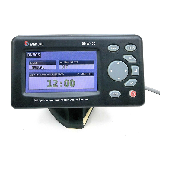
16 4.3 OPERATION SCREEN BNW-50’s current operational status appears on the screen. From menu, press ESC then will move to the operati
Page 9 — 2.1 OPERATIONAL MODES
17 4.4.1 OPERATION SETUP You can change and save the Operational mode, the dormant period, the delay between the 2nd & 3rd stage al
Page 10 — 2.4 EMERGENCY CALL
18 Activated : The dormant period timer will be operated. Deactivated : The dormant period timer will not be operated. AC
Page 11
19 The period of 1st stage bridge audible alarm Tone. You can change the Reset unit (BNW-52/52W)’s period of 1st stage bridge audible alar
Page 13 — 3.6 COMPONENTS
20 ※ However, if setting by use the additional visual indication and 1st stage bridge audible alarm, The ALARM UNIT A and B will cha
Page 15
22 4.5.1 OPERATION SETUP You can change and save the Operational mode, the dormant period, the delay between the 2nd & 3rd stage al
Page 16 — Checking the Password
23 4.5.2 SETUP ALARM UNITS On this menu, you may select the 2nd & 3rd stage remote audible alarm of the each processor unit’s interface termi
Page 17 — Operational mode
24 After changing the settings pressMENU, then you will be asked if you wish to save. Press » YES » then to
Page 18
25 You must be aware that by using this function, all the settings will initialize. Self Testing — Refer to 4.4.2 SYSTE
Page 19 — Self Testing
26 4.6 OPERATIONAL DESCRIPTION As shown on the right, «Operational Mode = Manual ON, Dormant period = 3 minutes, the delay between the 2n
Page 20 —
27 4.6.3 1ST STAGE BRIDGE AUDIBLE ALARM If not “RESET”, the BNW-50 will additionally sound a 1st stage bridge audible alarm on the bridge 15 secon
Page 22
29 4.6.7 MALFUNCTION INDICATION BNW-50 provides indication to the following malfunction. If the malfunction is activated, the display
Page 23 — 4.5.2 SETUP ALARM UNITS
3 QUICK USER MANUAL NAME [MENU] [ENT] [CHECK] [EMG] [ESC] [RES] [POWER] [DIRECTION] BUTTON MENU EMG ESC RES 1. PASSWORD SETTING ① When
Page 24 — Initialize
30 CHAPTER 5 BNW-51 (PROCESSOR UNIT) 5.1 LED FUNCTION (FRONT) Bridge Navigational Watch Alarm SystemProcessor UnitPOWER ALARMERRORAUTO TIMERB
Page 25 — Check the VDR DATA
31 5.2 POWER AND INTERFACE (BACK) DC FUSE(5A)FUSEINTERFACE110/220VACGND14FUSEAC FUSE(2A)28124VDC401327 1) AC Fuse (2A) : 2A is used as the
Page 26 — 4.6.2 VISUAL INDICATION
32 CHAPTER 6 INSTALLATION 6.1 POWER SUPPLY You should connect the Processor unit(BNW-51) to the Main power supply(AC 220V) using the AC cabl
Page 27
33 6.2.1 BRACKET MOUNTING Before installing, consider the display unit’s weight and search for the most convenient place for you. Instal
Page 28 — 4.6.6 EMERGENCY CALL
34 audible alarm period can be changed from the setup menu. By using the jump pin (CN3: Tone OFF) from internal PCB, the 1st stage
Page 29
35 6.6 2ND & 3RD STAGE REMOTE AUDIBLE ALARM (ALARM/A~G) Install the alarm unit (BNW-52) in the officer’s room or the captain’s roo
Page 31
37 6.10 NMEA INPUT (NMEA/RXD) You can connect the digital equipment which can output the NMEA data (reset, alert etc). Also, when digital
Page 32
38 CHAPTER 7 INSTALLATION CONSIDERATION 7.1 GENERAL The following requirements are included in IMO resolution MSC.128(75) concerning the i
Page 33 — 6.2.2 FLUSH MOUNTING
39 CHAPTER 8 MOTION SENSOR 8.1 OPERATING MOTION SENSOR We have adapted Doppler radar principle so the sensor can detect the microwave (MW) an
Page 34
4 CAUTION 1. This BNWAS can be switched ON/OFF or settings can be changed with password, therefore only authorized person (captain) can change or s
Page 35
40 3) Insert the adapter below the bracket
Page 36
41 Check the operation after the installment Move around in the detective range after installation and check if the Green lamp (PIR), Brown lamp
Page 37
42 CHAPTER 9 TEST AFTER INSTALLATION Go through the check list below after the installing the equipment. No. Check list OK 1 Turn on the BNW-5
Page 38 — 7.1 GENERAL
43 CHAPTER 10 MAINTENANCE AND FAULT DIAGNOSIS 10.1 SYSTEM MAINTENANCE Constant maintenance is required to maintain the functionality of the equ
Page 39 — CHAPTER 8 MOTION SENSOR
44 2 BNW-50 does not turn on Check the AC or DC fuse. Check the power of AC input (220V) and DC input (24V) Check the power cable’s connection. 3 R
Page 40
45 CHAPTER 11 NMEA SENTENCE (IEC 61162-1) BNW-50 provides the interface such as IEC 61162-1 ALR, EVE…etc with the message below. SETTINGS : Bi
Page 41
46 11.4 GLL – Geographic position This sentence is a primary source of position information for the transponder when connected to
Page 42
47 CHAPTER 12 PACKING LIST 12.1 BNW-50 (STANDARD) BNW-50(Display Unit Desktop) NO. Item External Feature STANDARD Q’ty CHK Remark BNW-50 1 D
Page 43 — Symptoms Solutions
48 2A/250V[20mmX5mm] 7 FUSE CODE NO. 527-2002-1Q 2 AC POWER 5A/250V[20mmX5mm] 8 FUSE CODE NO. 527-2005-1Q 2 DC Power 12.3 BNW-52 FLUSH
Page 44
49 12.6 BNW-52W WATERTIGHT TYPE (STANDARD) 12.7 BNW-52 DESK TYPE (OPTION) BNW-52(Reset unit desktop) NO. Item External Feature STANDARD Q’ty
Page 45
5 —- CONTENTS —- CHAPTER 1 ABOUT BNWAS …
Page 46 — 11.6 ZDA – Time and date
50 BNW-B(Desk type bracket) BNW-B 2 Bracket CODE NO. E02-1811-01 1 BNW-B-A(Desk type bracket installation accessory) M3X6 STS304 3 Bolt COD
Page 47 — Proc essor Unit
51 CHAPTER 13 DIAGRAMS 13.1 INTERCONNECTION DIAGRAM Ext Alarm1 PORTWatertightProcessor UnitDisplay UnitMotion SensorINTERCONNECTION DIAGRAMmax.
Page 48 — Alarm unit
52 13.2 INSTALLATION DIAGRAM ( EXAMPLE-1 ) 1SLDDISPLAYIN/OUT2 3 4TXD24VRXD212024VGNDALARME191824VGNDALARMD171624VGNDALARMC151424VGNDALARMB3130INP
Page 49
53 13.3 INSTALLATION DIAGRAM ( EXAMPLE-2 ) : Z8-2M-05A CABLE ASS’Y.: 6p shield(>UL2464-6C-24AWG): 2p shield(>UL2464-2C-20AWG): 3p shiel
Page 50
54 13.4 INSTALLATION DIAGRAM ( EXAMPLE-3 ) 1SLDDISPLAYIN/OUT2 3 4TXD24VRXD212024VGNDALARME191824VGNDALARMD171624VGNDALARMC151424VGNDALARMB7612VRE
Page 52 — PROCESS UNIT
56 13.6 BNW-51 OUTLINE DRAWING 220±1210±1198±1ALARMCBridge Navigational Watch Alarm SystemA1BCAUTOPOWER ERROR ALARM TIMERProcessor UnitBNW-5123 4
Page 53
57 13.7 BNW-52 FLUSH TYPE OUTLINE DRAWING BNW-52Reset unitA123 4 5 6 7 8 9BC108SAMYUNGResetto resetPush button126±1105.5ED29.7±126.24-Ø3.390±17666
Page 54
58 13.8 BNW-53 FLUSH TYPE OUTLINE DRAWING 12A345 6BCSAMYUNGto bridgeAssistanceAlarm unitBNW-53108126±17 8 990±176664-Ø3.3ED105.529 7±126 2
Page 55
59 13.9 BNW-52W WATERTIGHT TYPE OUTLINE DRAWING to resetAB1 2SAMYUNG3 4Push buttonResetReset unitBNW-525 6127±1178±17 8 9CDE22±1175±192.5±1
Page 57 — Reset unit
60 13.10 BNW-B FLUSH TYPE OUTLINE DRAWING (BNW-52,53) 66±11 2A3 4 5 6BC4-M3TAP4-Ø3,5Ø3554±17 8 976.6±190±1ED90±1108.2±1114±11.2±0.138±113±1
Page 58
61 13.11 MOTION SENSOR(DND-300M) OUTLINE DRAWING 1 32 4ABCDE122.8±15 6 7 8 958±1 79±1
Page 59
62 CHAPTER 14 WARRANTY INFORMATION Thank you for purchasing SAMYUNG ENC LTD’s BNW-50. This manual includes the proper way of operat
Page 60
7 CHAPTER 10 MAINTENANCE AND FAULT DIAGNOSIS…43 10.1 SYSTEM MAIN
Page 61 — 58±1 79±1
8 CHAPTER 1 ABOUT BNWAS The purpose of a bridge navigational watch alarm system is to monitor the bridge activity and detect operator disability
Page 62
9 CHAPTER 2 OPERATION OF BNWAS This BNW-50’s setting is only adjustable by using password, therefore only authorized person (captain)
We will keep fighting for all libraries — stand with us!
Internet Archive Audio
 Live Music Archive
 Librivox Free Audio
Featured
- All Audio
- This Just In
- Grateful Dead
- Netlabels
- Old Time Radio
- 78 RPMs and Cylinder Recordings
Top
- Audio Books & Poetry
- Computers, Technology and Science
- Music, Arts & Culture
- News & Public Affairs
- Spirituality & Religion
- Podcasts
- Radio News Archive
Images
 Metropolitan Museum
 Cleveland Museum of Art
Featured
- All Images
- This Just In
- Flickr Commons
- Occupy Wall Street Flickr
- Cover Art
- USGS Maps
Top
- NASA Images
- Solar System Collection
- Ames Research Center
Software
 Internet Arcade
 Console Living Room
Featured
- All Software
- This Just In
- Old School Emulation
- MS-DOS Games
- Historical Software
- Classic PC Games
- Software Library
Top
- Kodi Archive and Support File
- Vintage Software
- APK
- MS-DOS
- CD-ROM Software
- CD-ROM Software Library
- Software Sites
- Tucows Software Library
- Shareware CD-ROMs
- Software Capsules Compilation
- CD-ROM Images
- ZX Spectrum
- DOOM Level CD
Books
 Books to Borrow
 Open Library
Featured
- All Books
- All Texts
- This Just In
- Smithsonian Libraries
- FEDLINK (US)
- Genealogy
- Lincoln Collection
Top
- American Libraries
- Canadian Libraries
- Universal Library
- Project Gutenberg
- Children’s Library
- Biodiversity Heritage Library
- Books by Language
- Additional Collections
Video
 TV News
 Understanding 9/11
Featured
- All Video
- This Just In
- Prelinger Archives
- Democracy Now!
- Occupy Wall Street
- TV NSA Clip Library
Top
- Animation & Cartoons
- Arts & Music
- Computers & Technology
- Cultural & Academic Films
- Ephemeral Films
- Movies
- News & Public Affairs
- Spirituality & Religion
- Sports Videos
- Television
- Videogame Videos
- Vlogs
- Youth Media
Search the history of over 835 billion
web pages
on the Internet.
Search the Wayback Machine
Search icon
An illustration of a magnifying glass.
Mobile Apps
- Wayback Machine (iOS)
- Wayback Machine (Android)
Browser Extensions
- Chrome
- Firefox
- Safari
- Edge
Archive-It Subscription
- Explore the Collections
- Learn More
- Build Collections
Save Page Now
Capture a web page as it appears now for use as a trusted citation in the future.
Please enter a valid web address
- About
- Blog
- Projects
- Help
- Donate
- Contact
- Jobs
- Volunteer
- People
- About
- Blog
- Projects
- Help
-
Donate
Donate icon
An illustration of a heart shape - Contact
- Jobs
- Volunteer
- People
Bookreader Item Preview
Flag this item for
-
Graphic Violence
-
Explicit Sexual Content
-
Hate Speech
-
Misinformation/Disinformation
-
Marketing/Phishing/Advertising
-
Misleading/Inaccurate/Missing Metadata
texts
Samyung BNW — 50 User manual
- Topics
- manualzz, manuals, Samyung BNW — 50 manual, BNW — 50 pdf download, BNW — 50 User manual, Samyung user manuals, Samyung service instructions, BNW — 50 instructions, processors guides,
- Collection
- manuals_contributions; manuals; additional_collections
- Language
- English
- Addeddate
- 2020-11-09 19:46:02
- Identifier
- manualzz-id-42436
- Identifier-ark
- ark:/13960/t7sn9tk7r
- Ocr
- ABBYY FineReader 11.0 (Extended OCR)
- Page_number_confidence
- 100.00
- Ppi
- 600
- Scanner
- Internet Archive Python library 1.9.3
plus-circle Add Review
plus-circle Add Review
comment
Reviews
There are no reviews yet. Be the first one to
write a review.
21
Views
DOWNLOAD OPTIONS
download 1 file
ABBYY GZ download
download 1 file
DAISY download
For print-disabled users
download 1 file
EPUB download
download 1 file
FULL TEXT download
download 1 file
ITEM TILE download
download 1 file
KINDLE download
download 1 file
PAGE NUMBERS JSON download
download 1 file
PDF download
download 1 file
SINGLE PAGE PROCESSED JP2 ZIP download
download 1 file
TORRENT download
download 12 Files
download 6 Original
SHOW ALL
IN COLLECTIONS
Manuals: Contributions Inbox 
The Manual Library 
Additional Collections 
Uploaded by
chris85
on
SIMILAR ITEMS (based on metadata)
Terms of Service (last updated 12/31/2014)
Specifications:
|
Accompanying Data:
Samyung BNW — 50 Boating Equipment PDF Operation & User’s Manual (Updated: Wednesday 7th of September 2022 08:18:10 AM)
Rating: 4.5 (rated by 2 users)
Compatible devices: Carver OTC, Airtronic D2, BASE MASTER mini, AutoTrimPro, 406-S, BIMINI TOP, SRG-315DN, 4030.
Recommended Documentation:
Samyung BNW — 50: Text of Operation & User’s Manual
(Ocr-Read Version Summary of Contents, UPD: 07 September 2022)
-
43, 43 2 BNWAS does not turn on Check the AC or DC fuse.. Check the power supply of AC input power(220V) and DC input power (24V) Check the power cable’s connection. 3 Reset function does not work. Check the interface socket [RES1/LOW] of BNW-51 . Socket power (pin number 9~ 10) (It should be 0V only when reset button is pressed or m…
-
24, 24 Saving the VDR data by using the SD card (Record VDR data on SD card) After inserting the SD card, by using and , check the box and save by pressing MENU . «BNWAS_SAMYUNGENC_VDR.txt» file will be created in the SD card and at the same time VDR data will be saved in the file. BNW-50’s initial setup is as…
-
11, 11 2.3.2 Visual Alarm If no “RESET” button is entered during the time set (3~12 minutes), visual alarm will activate for the next 15 seconds. This gives time to “RESET” before the 1 st stage audible alarm gets activated. If “RESET” button is not entered within 15 seconds, 1 st stage audible alarm will activate. Timer…
-
25, 25 4.5 Operational display As shown on the right, «Alarm Mode = Manual ON, Dormant period = 3 minutes, Period between the 2 nd and 3 rd stage alarm=90seconds», the operational display of the display unit (BNW-51) will be explained with these settings. Refer to 2.3.1 Sequence of alarm to help you to understand …
-
48, 48 12.7 BNW-52 Watertight type(OPTION) 12.8 BNW-53 Desk type(OPTION) BNW-53(Alarm unit desktop) NO. Item External Feature STANDARD Q’ty CHK Remark BNW-53 1 ALARM UNIT SAMYUNG Assistance to bridge Alarm unit BNW- 53 CODE NO. E02-2800-00 1 BNW-B(Desk type bracket) BNW-B 2 Bracket CODE NO. E02-1811-01 1 BNW-B-A(Desk type bracke…
-
30, 30 5.2 Connector and interface socket (Back) 28 FUSE AC FUSE(2A) 110/220VAC GND 14 1 INTERFACE 40 27 13 24VDC DC FUSE(5A) FUSE 1 5 3 2 5 4 1. AC Fuse(2A) 2. AC POWER 2A is used as main power(AC) fuse Main Power(110/220V AC) 3. DC Fuse(5A) …
-
33, 33 In addition, few things need to be taken into account when deciding where to install. Microwave radiation can pass through the glass and nonmetallic walls, you must adjust the microwave’s range so that it does not exceed the room limits. Otherwise the motion in the next room or moving traffic along the outer sid…
-
56, 56 13.7 BNW-52 FLUSH TYPE OUTLINE DRAWING BNW- 52 1 2 A 3 4 5 6 B C Reset unit to reset Push button SAMYUNG Reset 7 8 9 E D 29.7± 1 126± 1 90± 1
… -
49, 49 12.9 Cable(OPTION) Reset unit and motion sensor installation cable NO. Item External Feature STANDARD Q’ty CHK Remark UL 2464 6C X 24 AWG 1 Cable CODE NO. 567-2406-1K C-2 C-4 LENGTH OPTION Watertight type Reset Unit installation cable UL 2464 2C X 20 AWG 2 Cable CODE NO. 576-2002-1K C-3 LENGTH OPTION Alarm unit…
-
29, 29 Chapter 5 BNW-51 (Processor Unit) 5.1 LED Operation (Front) Bridge Navigational Watch Alarm System Processor Unit POWER ALARMERRORAUTO TIMER BNW- 51 Name Function Color POWER LED lights up when power is connected Red LED AUTO LED lights up when AUTO is selected from the Operational mode Green LED ERROR LED lights up when the main or the back-up power is not supplied…
-
57, 57 13.8 BNW-53 FLUSH TYPE OUTLINE DRAWING 1 2 A 3 4 5 6 B C SAMYUNG BNW- 53 Alarm unit Assistance to bridge 126± 1 7 8 9 90± 1 E D 29.7± 1
… -
22, 22 After changing all the settings press MENU , then you will be asked if you wish to save, press “YES” then to save. 4.4.3 SYSTEM SETUP On this menu, you may update the software, initialize the system, check the version and set the alarm test mode. Version update ( Update ROM ) This function is …
-
51, 51 13.2 Installation Diagram ( Example-1 ) 19 GND ALARM 12V NMEA TXD PROCESS UNIT(BNW-51) TRAKFAIL ALARM UNITALARM UNITALARM UNITALARM UNITALARM UNIT C-1 C-2 C-3 C-4 ※ :yard supply C-4C-2 C-3 C-6 ALARM UNIT (OPTION,Max2) OFFICER CABINS : Z8-2M-05 CABLE ASS’Y. : 6p shield(>UL2464-6C-24AWG) : 2p shield(>UL2464-2C-20AWG) : 3p shield(>UL24…
-
12, 12 Chapter 3 PRODUCT SPECIFICATION 3.1 DISPLAY UNIT (BNW-50) SCREEN SIZE……………… 4.3 INCH TFT COLOR LCD, 480 X 272 PIXELS POWER CONSUMPTION ……………… 130 mA , POWER SAVE MODE 70 mA (24 V DC) SIZE ……………… 129 x 183 x 113.5 mm (H x W x D) WEIGHT ……………… 0.5Kg OPERATION TEMPERATURE ……………… -15 …
Samyung BNW — 50: Recommended Instructions
CB661EA, 5845 NFEY, GSS20, 101-1, C/AR-CF-01SC


-
READ THIS MANUALCAREFULLY BEFORE OPERATION!OWNER’S/OPERATOR’SMANUALLIT-18626-04-45FX140U.S.A. Edition2002WaveRunnerPrinted in USAFebruary 2002—2.2 × 1 CRF1B-F8199-10(FX1000-A)(E)Printed on recycled paperYAMAHA MOTOR CORPORATION, USA …
FX140 WaveRunner 2002 136
-
T H E W O R L D P O W E R I N A N C H O R I N G S Y S T E M S 21 July 2011 www.muir.com.au 1 VM/VMC 500/650 VR/VRC 1000/1200 VERTICAL WINDLASS …
Easy Weigh Series 31
-
NMALO ERMALONE AUTO RACKS, 81 County Road, Westbrook, Maine 04092Phone: 207-774-9100 Fax: 207-615-0551Website: www.maloneautoracks.com Email: [email protected] ArrowComponents Included: (8) Kayak Saddles — (16) 50mm Mounting Bolts — (16) SS Washers(16) Wing Nuts — (4) 15’ Green Cam Buckle Load Straps — (4) Safety Tie-DownsIns …
MPG461GU 2
-
MOVE TRAILERSOPERATOR’SGUIDEIncludes Safety, Use and Maintenance InformationWARNINGRead this user’s guide thoroughly. It contains important safety information.Keep this user’s guide for reference.219002242Original Instructions …
Sea-Doo MOVE Series 68
-
PATRIOT JACK DOCK ASSEMBLY INSTRUCTIONS Congratulations on your new Patriot Dock purchase! This manual contains instructions to assemble basic dock config-urations for use along a typical residential shoreline. Please read through entire instruction manual before starting. Please visit www.patriotdocks.com for step-by-step video instructions and more detail …
JACK DOCK 8
-
Inflatable Quick-Shade Top InstructionsA quick and easy way to gain shaded area on your Inflatable Boat. Topaccommodates boat widths to 5’7” lengths to 10’8” (West Marine 4Stroke Performance Series — SP4/5 and HP4/5) and is supported byshockcorded fiberglass pole framework that breaks down for con-venient storage. After initial installation of permanently mo …
Inflatable Quick-Shade Top 3
-
© Copyright 2008 Optoma Technology, Inc. DLP® and the DLP logo are registered trademarks of Texas Instruments. All specifications subject to change at any time.Datasheet – HD65Display Technology0.62” DarkChip2 DLP® Technology by Texas InstrumentsResolutionNative 720p (1280 x 720)Maximum Resolution1080p (1920 x 1080)Brightness1600 LumensContrast Ratio4000:1 (Full On/Full Off)Lamp …
HD65 1
-
Carbo Racing Foil Instruction ManualUnit 0, 1, 2, 3WARNING!: Strictly follow all instructions to avoid an accident, damage to your vessel, personal injury or death. See www.harken.com for additional safety information. …
Carbo Racing Foil 8
Additional Information:
Popular Right Now:
Operating Impressions, Questions and Answers:
USER MANUAL
BNW - 50
Bridge Navigational Watch Alarm System
Rev. M00-0481-00
1
2
CAUTION
1. This BNWAS can be switched ON/OFF or settings can be changed with password, therefore only
authorized person (captain) can change or switch ON/OFF the BNWAS.
2. Before operating the machinery, you must read and be fully aware of the safety signs and the
guidelines.
3. In case of machine breakdown due to the heat exposure or use of faulty power cable which can
cause a serious damage, is not covered by A/S.
4. Please do not disassemble the equipment since it is equipped with electric circuit that can be
only handled by experienced technician. Exposure of the display screen to the UV light may
cause life-shortening of the LCD. Avoid overheating LCD by adjusting the contrast except for
the extreme dark display. The problem caused by the overheating may not be solved after the
temperature has been cooled down
SIGN
DESCRIPTION
The PCB used in this equipment is produced under protected
environment of electrostatic discharge.
This is because the most of the semiconductor equipment used
in the PCB can be damaged easily by the electrostatic discharge.
You must prevent from damaging the equipment when
operating, as it can be easily damaged by the electrostatic
!
discharge.
Only experienced technician must work on the circuit of the
equipment as it is sensitive to electrostatic discharge.
Disassemble of this equipment is only allowed to the
technician authorized by our company.
Cleaning of the display screen
The surface of the screen is coated with non-reflective material, therefore it is important to clean and
take meticulous care when cleaning. Please follow the instructions below.
Use the cleaning spray (same as computer monitor), microfiber. Fold the tissue or the microfiber
three times, and wet the edge of the fiber with the spray. Use your index finger to wipe the monitor.
The screen may get damaged if the tissue is not wet enough.
When you require technical assistance, please contact the nearest SAMYUNGENC Store or the A/S
center.
3
----
CONTENTS
----
CHAPTER 1
ABOUT BNWAS .............................................................................................................................. 9
CHAPTER 2
OPERATION OF BNWAS ............................................................................................................. 10
2.1 OPERATION MODE...................................................................................................................................................................10
2.1.1
MANUAL ON Mode........................................................................................................................................................10
2.1.2
MANUAL OFF Mode.......................................................................................................................................................10
2.1.3
AUTO Mode .......................................................................................................................................................................10
2.2 DORMANT PERIOD SETUP....................................................................................................................................................10
2.3 OPERATING SEQUENCE..........................................................................................................................................................10
2.3.1
SEQUENCE OF ALARM ..................................................................................................................................................10
2.3.2
Visual Alarm .......................................................................................................................................................................11
2.3.3
1-stage Audible Alarm ..................................................................................................................................................11
2.3.4
2-stage Audible Alarm ..................................................................................................................................................11
2.3.5
3-stage Audible Alarm ..................................................................................................................................................11
2.3.6
Emergency Call .................................................................................................................................................................11
CHAPTER 3
PRODUCT SPECIFICATION.......................................................................................................... 12
3.1 DISPLAY UNIT (BNW-50)........................................................................................................................................................12
3.2 PROCESS UNIT (BNW-51)......................................................................................................................................................12
3.3 RESET UNIT (BNW-52).............................................................................................................................................................12
3.4 ALARM UNIT (BNW-53)..........................................................................................................................................................13
3.5 MOTION SENSOR (DND-300M) .........................................................................................................................................13
3.6 COMPONENTS ...........................................................................................................................................................................14
3.6.1
BNW-50 SPECIFICATION ..............................................................................................................................................14
3.6.2 BNW-50 OPTION SPECIFICATION ............................................................................................................................14
4
CHAPTER 4
BNW-50 (DISPLAY UNIT)............................................................................................................ 15
4.1 BUTTONS ......................................................................................................................................................................................15
4.2 SETTING PASSWORD...............................................................................................................................................................16
4.3 DISPLAY OF OPERATIONAL STATUS.................................................................................................................................17
4.4 MENU .............................................................................................................................................................................................17
4.4.1
SETUP ALARM ...................................................................................................................................................................18
4.4.2
SETUP ALARM DEVICES ................................................................................................................................................21
4.4.3
SYSTEM SETUP ..................................................................................................................................................................22
4.5 OPERATIONAL DISPLAY .........................................................................................................................................................25
4.5.1
DORMANT PERIOD .........................................................................................................................................................25
4.5.2
Visual alarm ........................................................................................................................................................................25
4.5.3
1st stage audible alarm..................................................................................................................................................26
4.5.4
2nd stage audible alarm ................................................................................................................................................26
4.5.5
3rd stage audible alarm .................................................................................................................................................27
4.5.6
Emergency call ..................................................................................................................................................................27
4.5.7
Failure indicator ................................................................................................................................................................28
CHAPTER 5
BNW-51 (PROCESSOR UNIT) ..................................................................................................... 29
5.1 LED OPERATION (FRONT) ........................................................................................................................................................29
5.2 CONNECTOR AND INTERFACE SOCKET (BACK)..........................................................................................................30
CHAPTER 6
INSTALLATION.............................................................................................................................. 31
6.1 POWER SUPPLY..........................................................................................................................................................................31
6.2 DISPLAY .........................................................................................................................................................................................31
6.2.1
BRACKET MOUNTING....................................................................................................................................................32
6.2.2
FLUSH MOUNTING .........................................................................................................................................................32
5
6.3 RESET SET UP ( RES1/LOW , ALARM/VIS+AUD) ..........................................................................................................32
6.4 MOTION SENSOR......................................................................................................................................................................32
6.5 INPUT TERMINAL FOR REMOTE ACTIVATION( REMOT/TRAK).............................................................................33
6.6 ADDITIONAL RESET TERMINAL ( RES2/LOW )..............................................................................................................33
6.7 PULSE RESET SET UP( RES3/PULS) .....................................................................................................................................33
6.8 NMEA INPUT ( NMEA/RXD ) ................................................................................................................................................33
6.9 NMEA OUTPUT( NMEA/TXD )..............................................................................................................................................34
6.10 EXTERNAL DAMAGE ALARM OUTPUT( ALARM/FAIL )...........................................................................................34
6.11 EXTERNAL EMERGENCY ALARM INPUT( EMERG/EXT )..........................................................................................34
6.12 VISUAL ALARM( VIS ) ............................................................................................................................................................34
6.13 1ST STAGE AUDIBLE ALARM( AUD ) .................................................................................................................................34
6.14 2ND STAGE AUDIBLE ALARM ( ALARM/A~G )..............................................................................................................35
6.15 3RD STAGE AUDIBLE ALARM ( ALARM/A~G ) ..............................................................................................................36
CHAPTER 7
INSTALLATION CAUTION ........................................................................................................... 37
7.1 GENERAL .......................................................................................................................................................................................37
7.2 LOCATION OF RESET UNIT (128/A4.1.3.1) .....................................................................................................................37
7.3 RESET INSTALLATION (128/A5.1.4) ...................................................................................................................................37
7.4 VISUAL ALARM (128/A5.2.2 PART).......................................................................................................................................37
7.5 1ST STAGE AUDIBLE ALARM(BRIDGE) (128/A5.2.3 PART)............................................................................................37
CHAPTER 8
MOTION SENSOR (MOVEMENT SENSOR) .............................................................................. 38
8.1 OPERATING MOVEMENT SENSOR ....................................................................................................................................38
8.2 INSTALLATING MOVEMENT SENSOR ..............................................................................................................................39
CHAPTER 9
TEST AFTER INSTALLATION ....................................................................................................... 41
CHAPTER 10
SYSTEM MAINTENANCE AND FAULT DIAGNOSIS.............................................................. 42
6
10.1 SYSTEM MAINTENANCE......................................................................................................................................................42
10.2 FAULT DIAGNOSIS .................................................................................................................................................................42
CHAPTER 11
NMEA(IEC 61162-1) INTERFACE ............................................................................................. 44
11.1 VDR INTERFACE.......................................................................................................................................................................44
11.2 EXTERNAL EQUIPMENT ALARM INTERFACE ..............................................................................................................44
11.3 EXTERNAL EQUIPMENT RESET INTERFACE .................................................................................................................44
CHAPTER 12
PACKING LIST ............................................................................................................................. 45
12.1 BNW-50 (STANDARD ) .........................................................................................................................................................45
12.2 BNW-51 (STANDARD ) .........................................................................................................................................................45
12.3 BNW-52 FLUSH TYPE (STANDARD) ..................................................................................................................................46
12.4 BNW-53 FLUSH TYPE (STANDARD) ..................................................................................................................................46
12.5 MONTION SENSOR (STANDARD)......................................................................................................................................47
12.6 BNW-52 DESK TYPE (OPTION) ............................................................................................................................................47
12.7
BNW-52 WATERTIGHT TYPE(OPTION).........................................................................................................................48
12.8 BNW-53 DESK TYPE (OPTION) ............................................................................................................................................48
12.9 CABLE (OPTION) ........................................................................................................................................................................49
CHAPTER 13. DIAGRAM...................................................................................................................................... 50
13.1 INTERCONNECTION DIAGRAM........................................................................................................................................50
13.2 INSTALLATION DIAGRAM (EXAMPLE-1 ) .....................................................................................................................51
13.3 INSTALLATION DIAGRAM (EXAMPLE-2 ) .....................................................................................................................52
13.4 INSTALLATION DIAGRAM (EXAMPLE-3 ) .....................................................................................................................53
13.5 BNW-50 OUTLINE DRAWING............................................................................................................................................54
13.6 BNW-51 OUTLINE DRAWING............................................................................................................................................55
13.7 BNW-52 FLUSH TYPE OUTLINE DRAWING .................................................................................................................56
7
13.8 BNW-53 FLUSH TYPE OUTLINE DRAWING .................................................................................................................57
13.9 BNW-52W WATERTIGHT TYPE OUTLINE DRAWING...............................................................................................58
13.10 BNW-B FLUSH TYPE OUTLINE DRAWING (BNW-52,53) .....................................................................................59
13.11 MOTION SENSOR(DND-300M) OUTLINE DRAWING...........................................................................................60
CHAPTER 14
8
WARRANTY INFORMATION .................................................................................................... 61
Chapter 1
ABOUT BNWAS
The purpose of a bridge navigational watch system is to monitor the bridge activity and detect
operator disability which could lead to marine accidents. The system monitors awareness of the Watch
officer and automatically alerts the Master or another qualified person if for any reason watch officer
becomes incapable of performing watch officer’s duties. This purpose is achieved by series of indications
and alarm to alert first the watch officer and, if he is not responding, then to alert Master or another
qualified person. Additionally, the BNWAS provide the watch officer with means of calling for immediate
assistance if required. BNWAS must operate whenever heading or track control system is interlocking
unless prohibited by the captain.
Maritime Safety Committee (MSC) from IMO requires BNWAS that meets the new IMO performance
standard requirement.
Existing Vessel requires to install the equipment before the first inspection after the below date.
▷ Existing passenger ship and Vessels under 3000t: 1st JULY 2012.
▷ Existing vessels over 500t: 1st JULY 2013..
▷ Existing vessels over 150t: 1st July 2014.
New Vessel must install the equipment by:
▷ New Vessels over 150t, and vessels constructed after the 1st July 2011 must be equipped with
Bridge Navigational Watch System (BNWAS).
The equipment complies below standards :
IMO A.694(17) : General desired term for vessel radio equipment and electronic navigational
support
IMO A.830(19) : Code for alarm and command.
IMO MSC. 128(75) : Performance standard for BNWAS.
IMO MSC/Circ. 982 : Layout and guidelines for bridge equipment’s ergonomic standards.
IEC 62616 : Method to test the BNWAS’ technical characteristic..
IEC 60945 : Test method and result on marine navigation and radio communication
equipment.
IEC 62288 : Test method and result on marine navigation information display-desired terms
IEC 61162 : Marine navigation and radio communication equipment system- digital
interface..
9
Chapter 2
Operation of BNWAS
This BNWA’s setting is only adjustable by using password, therefore only authorized person (captain)
can switch ON/OFF and change the setting of the system.
However, when BNWAS is active with alarm, mode setting is not adjustable.
2.1
Operational Mode
2.1.1 MANUAL ON Mode
On this mode, BNW-50 operates constantly.
2.1.2 MANUAL OFF Mode
On this mode, BNW-50 does not operate under any circumstances.
2.1.3 AUTO Mode
On this mode, BNWAS system operates automatically once vessel’s heading or the track control system
(when signal has been inputted) is operating (refer to 6.5 input terminal for remote activation).
2.2
DORMANT PERIOD SETUP
Dormant period (3~12 minutes), 2nd alarm and 3rd alarm period (90~180seconds) are adjustable. The
Dormant period is always displayed on the main display unit of BNW-50.
2.3
OPERATING SEQUENCE
2.3.1 SEQUENCE OF ALARM
Dormant
3~12 min
Visual Alarm
15 sec
1st Alarm
15 sec
2nd Alarm
90~180 sec
Visual Alarm
1st Alarm
2nd Alarm
3rd Alarm
10
3rd Alarm
Reset
Dormant
Timer Start
2.3.2 Visual Alarm
If no “RESET” button is entered during the time set (3~12 minutes), visual alarm will activate for the
next 15 seconds. This gives time to “RESET” before the 1st stage audible alarm gets activated. If “RESET”
button is not entered within 15 seconds, 1st stage audible alarm will activate. Timer’s “RESET” can be
inputted in two different ways.
Manual way of using “RESET BUTTON” on the bridge.
Automatic way of using ‘Motion sensor” that detects the movement on the bridge.
2.3.3 1-stage Audible Alarm
This audible alarm is installed on the bridge and must be able to wake the watch officer. Visual alarm
and 1st stage audible alarm will activate and can be turned off by resetting the timer by inputting
“RESET”. If timer is not “RESET” after 15 seconds, 2nd stage audible alarm will activate.
2.3.4 2-stage Audible Alarm
This alarm is installed in the officer’s cabin or captain’s cabin. 2nd stage audible alarm is triggered if
timer is not “RESET” within the 15 seconds after 1st stage audible alarm is triggered. 1st stage and 2nd
stage audible alarms are both triggered at this stage.
2.3.5 3-stage Audible Alarm
This alarm is installed in the crew members’ cabin. If no actions are taken within 90 seconds after the
2nd audible alarm is triggered, 3rd stage audible alarm will activate. To give enough time for the back-up
officer or the captain to take an action after the 2nd stage audible alarm is triggered, you can adjust the
time from 90~180 seconds(3 minutes) between the 2nd stage and 3rd stage audible alarm. Also, until
“RESET” is inputted, all alarms stays activated.
2.3.6 Emergency Call
BNW-50 has built-in emergency call function, and if this button is pressed down for 2 seconds, 2nd stage
audible alarm is immediately triggered, and if no action is taken then 3rd stage audible alarm will
activate. Watch officer can call for help using this button if needed.
You can stop the emergency alarm if you press down the button for 2 seconds.
11
Chapter 3
3.1
PRODUCT SPECIFICATION
DISPLAY UNIT (BNW-50)
SCREEN SIZE……………… 4.3 INCH TFT COLOR LCD, 480 X 272 PIXELS
POWER CONSUMPTION ……………… 130 mA , POWER SAVE MODE 70 mA (24 V DC)
SIZE ……………… 129 x 183 x 113.5 mm (H x W x D)
WEIGHT ……………… 0.5Kg
OPERATION TEMPERATURE ……………… -15 ℃ ~ 55 ℃
3.2
PROCESS UNIT (BNW-51)
AC POWER SUPPLY
……………… 110V / 220V AC
DC POWER SUPPLY
……………… 24V DC
POWER CONSUMPTION
SIZE
……………… 130mA
……………… 221 x 165 x 95 mm ( H x W x D )
WEIGHT
……………… 1.5Kg
OPERATION TEMPERATURE
INTERFACE ………………
……………… -15 ℃ ~ 55 ℃
Inputting reset pulse by radar.
Inputting interface of operating heading or track controller
Inputting NMEA data(Reset, alarm, etc)
Inputting DC12V power supply and reset of motion sensor and reset unit.
Outputting the alarm signal for reset and alarm unit.
Outputting the NMEA data for blackbox(VDR)
Outputting the alarm interface for machine breakdown
Outputting the interface for the external unit’s alarm.
INPUT/OUTPUT DC23V power supply and RS-232 communication for display unit.
3.3
RESET UNIT (BNW-52)
POWER CONSUMPTION
SIZE
……………… max 34mA / unit (24 V DC)
……………… 126x90x30 mm ( H x W x D )
WEIGHT
……………… 0.2Kg ( FLUSH TYPE ), 0.5Kg ( DESK TYPE ), 0.5Kg ( WATERTIGHT TYPE )
OPERATION TEMPERATURE
……………… -15 ℃ ~ 55 ℃
LEVEL OF WATER RESISTANCE
LEVEL OF SOUND
FUNCTION
……………… OVER 75 dB
……………… Reset, visual alarm, 1st stage audible alarms are combined (You may choose one
function if you wish to).
12
……………… IP67(WATERTIGHT TYPE)
3.4
ALARM UNIT (BNW-53)
POWER CONSUMPTION
SIZE
……………… max 30mA / unit (24 V DC)
……………… 126x90x30 mm ( H x W x D )
WEIGHT
……………… 0.2Kg ( FLUSH TYPE ), 0.5Kg ( DESK TYPE )
OPERATION TEMPERATURE
LEVEL OF SOUND
3.5
……………… -15 ℃ ~ 55 ℃
……………… OVER 75 dB
MOTION SENSOR (DND-300M)
POWER CONSUMPTION ……………… OPERATING = 26mA / unit ,
STAND-BY= 17mA / unit (12 V DC)
DETECTION METHOD ……………… Quad-element PIR and microwave pulse Doppler
MW frequency …………… 10.525GHz
SIZE ……………… 115 x 61 x 37.5 mm ( H x W x D )
WEIGHT ……………… 120g (BRACKET EXCLUDED)
OPERATION TEMPERATURE ……………… -15°C~ 55°C
DETECTIVE ANGLE ……………… 120°~150°
DETECTIVE RAGE ……………… 15m ( STANDARD )
PRE-HEATING TIME ……………… 1 MINUTE
※ TOTAL POWER CONSUMPTION FOR STANDARD COMPONENTS (REFER 13.2 Installation Diagram)
Display Unit(BNW-50)
.……………… 1 EA
Processor Unit(BNW-51)
.……………… 1 EA
Reset Unit(BNW-52)
.……………… 3 EA
Alarm Unit(BNW-53)
………………
Motion Sensor(DND-300M)
TOTAL (24V DC)
7 EA
………………
2 EA
……………… APPROX 0.6A
13
3.6
COMPONENTS
3.6.1 BNW-50 SPECIFICATION
NO
NAME
MODEL NAME
QUANT
REMARK
1
Display unit desktop
BNW-50
1 SET
1-2
Display unit installation accessory
BNW-50-A
1 SET
1-3
USER MANUAL
BNW-50-MK
1 EA
2
Processor unit desktop
BNW-51
1 SET
2-2
Processor unit installation accessory
BNW-51-A
1SET
3
Reset unit desktop
BNW-52
3 SET
Additional installation available
3-2
Reset unit installation accessory
BNW-52-A
3 SET
Flush type
4
Alarm unit desktop
BNW-53
7 SET
Additional installation available
4-2
Alarm unit installation accessory
BNW-53-A
7 SET
Flush type
5
Motion sensor(installation accessory
DND-300M
2 SET
Additional installation available
Bracket, protection cover included
M00-0481-00
included)
3.6.2
BNW-50 OPTION SPECIFICATION
1
WATERTIGHT reset unit desktop
BNW-52W
1SET WATERTIGHT type
2
WATERTIGHT reset unit install. accessory
BNW-52W-A
1SET WATERTIGHT type
3
Desk type bracket
BNW-B
1SET Desk type
4
Desk type bracket install. accessory
BNW-B-A
1SET Desk type
5
Reset unit, motion sensor install. cable
UL2464-6C-24AWG
1SET Optional length
6
WATERTIGHT reset unit install. cable
UL2464-6C-20AWG
1SET Optional length
7
Alarm unit install. Cable (Small)
UL2464-2C-20AWG
1SET Optional length
8
Alarm unit install. Cable (Large)
CVV-SB 1.25SQMM X 2C
1SET Optional length
14
Chapter 4
BNW-50 (DISPLAY UNIT)
- Rated input voltage DC 24V
!
4.1
(NOTE) Program version may change without notice for
performance improvement.
BUTTONS
BNW-50
EMG
MENU
ESC
RES
Bridge Navigational Watch Alarm System
Button
Function
Pressing down this button for 2 seconds will activate the emergency
EMG
call function.
By pressing down for another 2 seconds will deactivate the alarm.
MENU
Used to get into the menu function and message will appear if you
wish to save after the setup.
ESC
Note
EMERGENCY
Call
MENU
Brings you back to the previous page.
ESCAPE
Enter key allows you to select the menu or the individual menu.
ENTER
Used to verify the password.
CHECK
15
Reset input function activates.
RES
RESET
System stops operating and goes into sleep mode by pressing this
button and entering the password.
In order to deactivate the sleep mode, press this button again and
Sleep mode
enter the password.
- Main screen
Left, Right : Adjust the brightness of LCD
UP : Key sound ON
Down : Key sound OFF
Control key
- Otherwise
Used to move into the selected function or change the setting.
4.2
SETTING PASSWORD
Once power is connected to the equipment, this screen
will show. Captain may set the password that he should
only know.
If you wish to change the password, select SYSTEM
SETUP
Initialize then reset the password again on
this screen. However this function will initialize all the
setup. Therefore beware before using it. (Refer to 4.4.3
SYSTEM SETUP)
When entering password
->
(select numbers) ->
you wish to save and press YES if you wish to save then press
16
->
again.
message will appear if
4.3
DISPLAY OF OPERATIONAL STATUS
ESC
BNWAS’ current operational status appears on the screen. From menu, press
then will move
to the operational status display.
Alarm mode
Alarm state
Dormant period
4.4
MENU
Adjusting the system of BNW-50 can be done on the Menu screen. Password is required when
entering into the menu therefore adjusting the setting can be only done by authorized person (captain).
Checking the password
In order to get to the menu, password is required.
MENU
When
is pressed "CHECK MASTER PASSWORD" appears, then use
insert numbers, then
->
and
to
leads to the main menu.
But, when the alarm is triggered, you cannot get an access into the main menu and if alarm is
triggered in the middle of the setup process, it will take you to the operational status screen.
17
4.4.1 SETUP ALARM
You can change and save the ‘alarm mode’, ‘dormant
period’, ‘interval between 2nd and 3rd stage’, ‘use of
additional reset socket’, ‘interval of 1st stage audible
alarm’. All functions can be changed by using
and
buttons.
Setting alarm mode
① OFF Mode : BNW-50 does not operate under this mode. On the operational status, it shows
“MANUAL” for MODE and “OFF” for ALARM STATE
② MANUAL Mode : Under this mode, BNW-50 always operates. On the operational status, it shows
“MANUAL” for MODE and “ACTIVE” for ALARM STATE.
③ AUTO Mode: Under this mode, BNWAS system is
activated when vessel’s heading or track control system
operates. (Refer to 6.5 INPUT TERMINAL FOR REMOTE
ACTIVATION)
18
Deactivated : Mode on the operational status display
will show “AUTO”, and “STANBY” for ALARM
STATE as shown on the diagram below.
Activated : Mode on the operational status display will show “AUTO”, and “ACTIVE” for ALARM STATE.
Setting dormant period and the period between the second and third alarm.
You can control the Dormant period (3~12minutes) and the period between the second and third alarm
(90~180 seconds).
Go onto the SETUP ALARM display by inserting the password. Then use
change the timer.
and
buttons to
Also, on the operational status display of the unit(BNW-50) will always show the value of dormant
period.
19
Using the additional visual alarm and 1st stage audible alarm. (Additional reset unit)
When using the additional reset unit on this equipment, through the Alarm A & B interface terminal,
you can activate the visual alarm (VIS) or the 1st stage audible alarm (AUD) same as the standard reset
terminal,
Move the cursor to the wanted menu then press
, then you may decide the use of additional
reset unit.
Changing the period of the 1st stage audible alarm’s warning alert.
You can change the Reset unit (BNW-52)’s interval of
the 1st stage audible alarm’s warning alert by using this
function.
By using
and
buttons, you can change the
period of the alarm.
MENU
After changing the settings press
, then you
will be asked if you wish to save. Press “YES” then
to save.
20
4.4.2 SETUP ALARM DEVICES
On this menu, you may turn ON/OFF the alarm of the
each processor unit’s interface terminal ALARM A~G by
using
and
. Right bottom picture with
checked boxes means activating the 2nd stage audible
alarm, and the rest means activating 3rd stage audible
alarm. (Refer to 6.14 2nd stage audible alarms)
eg) Not using the additional visual alarm and 1st stage audible alarm
- Activate (ON) 2nd stage audible alarm : Alarm A, B, C
- Activate (ON) 3rd stage audible alarm : Alarm D, E, F, G
Also, by using the additional reset unit, you can activate (ON) the visual alarm(VIS) and the 1st stage
audible alarm(AUD) same as the standard reset terminal, through the Alarm A & B interface terminal.
eg) Using the visual alarm and the 1st stage audible alarm.
- Activate (ON) the visual alarm : A
- Activate (ON) the 1st stage audible alarm : B
- Activate (ON) the 2nd stage audible alarm : C
- Activate (ON) the 3rd stage audible alarm : D, E, F, G
21
MENU
After changing all the settings press
, then
you will be asked if you wish to save, press “YES”
then
to save.
4.4.3 SYSTEM SETUP
On this menu, you may update the software, initialize
the system, check the version and set the alarm test
mode.
Version update ( Update ROM )
This function is used when updating the display unit
version,
and
figures
"S00.017(2011.07.12)"and
"D0
0.017(20 11.07.12)" shown on the right side means the
display unit’s version of the each processor unit.
Initialize
When you wish to initialize the setting, move the cursor
to "Initialize" then press
, then you will be asked if
you wish to initialize. Move to “YES” then press
.
This will initialize the system and you will be brought
to the password setting screen (as shown on the
picture below). You must be aware that by using this function, all the settings will initialize.
22
Alarm test mode ( Test Mode )
By using this function, you can check if unit operates properly after installing the reset unit and the
alarm unit. You can check the visual alarm, 1st stage audible alarm and other connected alarms
immediately.
Move cursor to the test mode by using
then press
, this will activate the alarm.
However, when setting the additional visual alarm and 1st stage audible alarm, Alarm A and B will
change to the visual alarm and 1st stage audible alarm. ( Refer to 4.4.2 SETUP ALARM DEVICES )
23
Saving the VDR data by using the SD card (Record VDR data on SD card)
MENU
After inserting the SD card, by using
and
, check the box and save by pressing
.
"BNWAS_SAMYUNGENC_VDR.txt" file will be created in the SD card and at the same time VDR data will
be saved in the file.
BNW-50’s initial setup is as shown below.
24
4.5
Operational display
As shown on the right, "Alarm Mode = Manual ON,
Dormant period = 3 minutes, Period between the 2nd
and
3rd
stage
alarm=90seconds", the
operational
display of the display unit (BNW-51) will be explained
with these settings.
Refer to 2.3.1 Sequence of alarm to help you to
understand further.
4.5.1 Dormant period
Alarm will not trigger for 3 minutes and time will decrease. If watch officer reset the timer within 3
minutes, then timer will restart.
The reset of the timer can be done in 3 different ways. For the additional reset input using additional
unit, refer to 6.6~6.8.
RES
Manual way of pressing"
button" from the display unit of BNW-50.
Manual way of using the “RESET BUTTON” on the reset unit of BNW-52.
Automatic way of using “MOTION SENSOR” which detects the movement on the bridge floor.
4.5.2 Visual alarm
If watch officer has not reset the timer within 3 minutes, visual alarm will activate. On ALARM STATE,
“VISUAL ALARM” will be displayed and the elapsed time “0:10” will be shown in Red/Black. If timer has
been reset within 15 seconds after the visual alarm activates, then the timer will restart from 3 minutes.
25
4.5.3 1st stage audible alarm
If watch officer has not reset timer within 15 seconds after the visual alarm has been activated, 1st stage
audible alarm will activate. “1st ALARM” will be shown on the display under ALARM STATE, and the
elapsed time “0:23” and the 1st alarm will be shown in Red/black. At this status, visual alarm and 1st
stage audible alarm are activated at the same time. If reset is inputted within 15 seconds after the 1st
stage audible alarm is triggered, then the timer will restart from 3 minutes.
4.5.4 2nd stage audible alarm
2nd stage audible alarm will activate if timer has not been reset within 15 seconds after 1st stage audible
alarm is activated. “2nd ALARM” will be shown on the ALARM STATE, and the elapsed time “0:45” and
the “2nd ALARM” will be written in Red/Black. Visual alarm, 1st stage audible alarm and 2nd stage audible
alarm are activated at the same time. If timer has been reset within the period set between 2nd stage
and 3rd stage audible alarm (90 seconds), it will restart from 3 minutes.
26
4.5.5 3rd stage audible alarm
3rd stage audible alarm will activate if the timer has not been reset within 90 seconds after the 2nd stage
audible alarm is activated. On the display, “3RD ALARM” will be shown under ALARM STATE and the “3RD
ALARM” and the elapsed time “2:09” will be shown in red/black. On this status, all the alarms connected
to the BNWAS are triggered at the same time. If timer has been reset after this, the time restarts from 3
minutes.
4.5.6 Emergency call
EMG
By pressing the button
down for 2 seconds, 2nd stage audible alarm will activate immediately. If
no actions are taken then 3rd stage audible alarm will automatically activate. On the screen, “2nd Alarm”
will be displayed under ALARM STATE and soon “3rd ALARM” will be shown. “2nd, 3rd ALARM” and the
“EMERGENCY!!” will be written in black. After the emergency call function has been deactivated, then
you must go back to the previous set up status and set the timer from 3 minutes.
By pressing down the button for 2 seconds will deactivate the emergency call.
27
4.5.7 Failure indicator
When main power(110/220V AC) or back-up power(24V DC) is not connected, “Main Power Failure” or
“Back Up Power Failure” will appear on the top of the display in red/black writings.
Pictures below show Main Power Failure (Left) and Back Up Power Failure (right).
28
Chapter 5
5.1
BNW-51 (Processor Unit)
LED Operation (Front)
POWER AUTO
ERROR ALARM TIMER
BNW- 51
Processor Unit
Bridge Navigational Watch Alarm System
Name
POWER
Function
LED lights up when power is connected
Color
Red LED
AUTO
LED lights up when AUTO is selected from the Operational mode
ERROR
LED lights up when the main or the back-up power is not supplied.
ALARM
LED lights up when BNWAS’ system alarm is activated.
Brown LED
TIMER
LED lights up when the BNWAS’ system reset counter is activated.
Brown LED
Green LED
Red LED
29
5.2
Connector and interface socket (Back)
1
5
3
INTERFACE
AC FUSE(2A)
DC FUSE(5A)
13
1
FUSE
FUSE
27
14
28
110/220VAC
40
GND
24VDC
5
2
1. AC Fuse(2A)
2. AC POWER
2A is used as main power(AC) fuse
Main Power(110/220V AC)
3. DC Fuse(5A)
4. DC POWER
5A is used as Back-up power(DC) fuse
Back up power(24V DC)
4
5. INTERFACE Socket
DC24V power supply and RS-232 communication INPUT/OUTPUT (1~5 PIN) of display unit
DC12V Power supply and RESET INPUT (6~10 PIN) for motion sensor and reset unit.
Alert signal output (11~27 PIN) for reset and alarm unit.
Alert interface output (28~29 PIN) for machinery breakdown.
Interface input (30~31 PIN) for activing track controller.
NMEA data output (32~34 PIN) for blackbox (VDR)
NMEA data(reset, alarm…etc) input (35~36 PIN)
Reset pulse input (37~38 PIN) for radar.
ALARM
VIS+AUD
ALARM ALARM ALARM ALARM ALARM ALARM ALARM
A
B
C
D
E
F
G
ALARM REMOT
FAIL TRAK
1 2 3 4 5 6 7 8 9 10 11 12 13
14 15 16 17 18 19 20 21 22 23 24 25 26 27
28 29 30 31 32 33 34 35 36 37 38 39 40
SLD
RXD
TXD
24V
GND
12V
RES
12V
RES
GND
VIS
AUD
GND
24V
GND
24V
GND
24V
GND
24V
GND
24V
GND
24V
GND
24V
GND
OUT+
OUTINP+
INPTXD+
TXDSLD
RXD+
RXDINP+
INPINP+
INP-
Interface input (39~40 PIN) for external equipment alert.
DISPLAY
IN/OUT
30
RES2
LOW
RES1
LOW
NMEA
TXD
NMEA RES3 EMERG
RXD PULS EXT
Chapter 6
6.1
Installation
Power supply
You should connect the Processor unit(BNW-51) to the Main power supply(AC 220V) using the AC cable,
and DC cable should be connected to the vessel’s battery(DC24V) which can produce power to the
BNWAS
6.2
for more than 6 hours.
Display
You may choose an installation method between bracket mounting and the flush mounting for the
display unit (BNW-50). Connect the display unit (BNW-50) with the processor unit (BNW-51) with cable
(Z8-2M-05) provided.
4
24V
5
GND
3
TXD
SLD
1
BNW-50
2
RXD
DISPLAY
IN/OUT
BNW-51
Power connector
Interface socket
Display unit (BNW-50)
Processor unit (BNW-51)
Color of the cable
Interface socket
(Z8-2M-05)
number
Black (Shield)
1(SLD)
Shield
Black (GND)
5(GND)
GND
2
Not in use
-
-
3
White(RS-232 Output)
2(RXD)
RS-232 Input
4
Green(RS-232 Input)
3(TXD)
RS-232 Output
5
Red(DC24 Input)
4(24V)
DC24 Output
6,7,8
Not in use
-
-
Pin number
1
Function
31
6.2.1 Bracket Mounting
Before installing, consider the display unit’s weight and
search for the most convenient place for you.
Installing the display :
1) Hold the display and find the joint between the
bracket and the display.
2) Push the display gently into the bracket.
3) Turn the knob to lock.
Detaching the display :
1) Turn the unit off.
2) Loosen the knob and dismantle the end of the
bracket.
6.2.2 Flush mounting
1) Find the place to install the flush mounting.
2) Make a hole on the place you wish to install.
3) By using a saw, cut the panel
4) Make 4 holes for the screws
5) Install the screw on the display unit and put screws into the holes.
6) Attach the supplied hardware to the place you wish to install
display unit.
Before you begin, make sure you have enough space to install the display unit.
6.3
RESET SET UP ( RES1/LOW , ALARM/VIS+AUD)
Connect the reset unit (BNW-52) to the interface socket (RES1) of BNW-51, Reset unit is usually installed
near the visual alarm, however this reset unit combines the visual alarm and the 1st stage audible alarm
together, therefore there is no need to install them separately.
Reset function should be installed near the approachable place from conning position, workstation for
navigating and maneuvering.
Also you have installation options depending on the place you wish to install the reset unit (BNW-52).
(Flush type, desk type, watertight type).
6.4
Motion Sensor
Install the dual motion sensor (DND-300M) which consists of microwave and PIR detection. Connect the
2 power supply wires to +12V and -12V. And connect one of the relay wires to the [relay] socket as
shown below. When installing the motion sensor, use the standard bracket. (Refer to chapter 8. Motion
Sensor.
32
In addition, few things need to be taken into account when deciding where to install.
Microwave radiation can pass through the glass and nonmetallic walls, you must adjust the
microwave’s range so that it does not exceed the room limits. Otherwise the motion in the next room or
moving traffic along the outer side of the wall will cause the MW detector to trip.
Large reflective objects (especially metals) within the range may distort the patterns of the detective
range.
If two motion sensors are installed in the same room or on the opposite sides of a shared wall, the
sensors should not face each other and there must be at least 2 m distance between them.
6.5
Input terminal for remote activation( REMOT/TRAK)
Connect the ship’s heading or track control system to the remote activation input. Under the AUTO
mode, two brackets (INP+ / INP-) should be in contact for BNWAS to activate.
6.6
Additional reset terminal( RES2/LOW )
You can connect additional external reset unit or the motion sensors to this unit. By setting the display
unit, if ALARM A&B(one of the external alarm terminals) are used as Visual alarm (VIS) and Audible
alarm (AUD), this can be same as the standard reset unit. (Refer to 4.4.2 SETUP ALARM DEVICES)
6.7
Pulse reset set up( RES3/PULS)
Connect the additional equipment that could exist on the bridge in this input, where watch officer
could easily monitor. A high or low pulse will reset timer. You must be aware that periodic pulse signal
may automatically reset the timer.
6.8
NMEA Input ( NMEA/RXD )
You can connect the digital equipment which can output the NMEA data (reset, alert etc). Refer to the
chapter 11 NMEA (IEC 61162-1) interface section.
When digital equipment which can output the GPS data gets connected, there will be time shown on
the display.
33
Reset data : EVE sentence
Alarm data : ALR sentence
GPS data : GGA, RMC sentence
6.9
NMEA Output( NMEA/TXD )
According to the IEC 61162-1, ALR sentence, connect VDR and equipment that requires BNWAS’ NMEA
alarm data. Alarm data can output any changes made on the BNWAS such as reset alert, dormant
period time, etc. For further information on the alarm data, refer to the chapter 11 NMEA(IEC 61162-1)
interface.
6.10
External damage alarm output( ALARM/FAIL )
Connect the damage alarm output to the external alarm. These two terminals are usually connected
however when the display unit shows ‘Damage alert’ they will disconnect.
6.11
External emergency alarm input( EMERG/EXT )
Connect the two contacts of the external emergency call device to this terminal. When these two
terminals(INP+/INP-) become in contact for more than 2 seconds, system’s emergency call function
activates. When the external emergency call’s terminal gets disconnected, it will stop operating the
emergency call will stop operating. It is possible to connect the alarm contact signal coming from the
outside with this terminal.
6.12
Visual alarm( VIS )
You do not have to install the visual alarm separately as standard reset unit(BNW-52) is equipped with
the visual alarm function. The dimming of the visual alarm can be controlled automatically, and the
potentiometer (VR2:DIM) from internal PCB may also additionally adjust the dimming. Also, the visual
alarm can be stopped by the internal PCB’s jump pin (CN4:Lamp OFF).
6.13
1st stage audible alarm( AUD )
There is no need to install the 1st stage audible alarm separately as the standard reset unit(BNW-52) is
combined with it. The volume of the alarm is controlled by the reset unit’s PCB Potentiometer(VR1 :
Tone vol)
The alarm tone is adjustable by moving the jump pin(CN5, CN6, CN7 : tone) within PCB, and the 1st
stage alarm period can be changed from the setup menu. By using the jump pin (CN3:Tone OFF) from
internal PCB, the 1st stage audible alarm can be stopped.
34
6.14
2nd stage audible alarm ( ALARM/A~G )
Install the alarm unit (BNW-52) in the officer’s room or the captain’s room when there is only one
backup officer. When there are more than 1 backup officer, then install the alarm unit(BNW-53) in every
officers’ rooms separately.
Alarm unit(BNW-53) gives you installation options(flush mounting or desk type) depending on where
you are installing the unit.
Also all the alarm units’(BNW-53) alarm tone can be changed by moving the internal PCB’s jump
pin(CN2,4: Tone-H / CN3,5: Tone-L), volume of the alarm can be controlled by the internal PCB’s
potentiometer (VR1: Tone vol)
Backup officer’s decision
You can ignore the sequence of the audible alarm when connecting it to ALARM/A ~ ALARM/G, as you
can reassign the sequence of the connected alarm unit and the alarm type from the display unit (Refer
to 4.4.2 SETUP ALARM DEVICES).
Preset value when manufactured ( 2nd stage audible alarm can be selected separately )
ALARM/A
: 2nd stage audible alarm – officer’s cabin 1 connection terminal.
ALARM/B
: 2nd stage audible alarm – officer’s cabin 2 connection terminal
ALARM/C
: 2nd stage audible alarm – officer’s cabin 3 connection terminal.
ALARM/D
: 2nd stage audible alarm – officer’s cabin 4 connection terminal.
ALARM/E
: 3rd stage audible alarm - crew’s quarter’s connection terminal.
ALARM/F
: 3rd stage audible alarm – crew’s quarter’s connection terminal.
ALARM/G
: 3rd stage audible alarm – crew’s quarter’s connection terminal.
For example, you may adjust the setting as below.
ALARM/A
: Visual alarm terminal ( additional function same as the standard visual alarm)
ALARM/B
: 1st stage audible alarm terminal (additional function same as the standard 1st stage
audible alarm)
ALARM/C
: 2nd stage audible alarm – officer’s cabin 1 connection terminal
ALARM/D
: 2nd stage audible alarm – officer’s cabin 2 connection terminal
ALARM/E
: 2nd stage audible alarm – officer’s cabin 3 connection terminal
ALARM/F
: 3rd stage audible alarm – crew’s quarter’s connection terminal.
ALARM/G
: 3rd stage audible alarm – crew’s quarter’s connection terminal.
If you install the audible alarm to ALARM/A ~ ALARM/G separately as above, you may selectively
turn ON/OFF the alarm for each cabin, however this will create many wires.
You can minimize the wires by tying them (distinguish between officer’s cabin and the crew’s
quarter) if you do not have to turn ON/OFF the alarm per cabin.
35
6.15
3rd stage audible alarm ( ALARM/A~G )
Install the alarm unit (BNW-53) in the crewmember’s room who can respond to the 3rd stage alarm. At
this stage, all connected alarms will activate.
Delay setup for 2nd stage alarm’s timer
In large vessels, the delay between the 2nd and 3rd stage alarms may be set to a longer value when
installing, from 90~180 seconds maximum. To allow enough time for the back-up officer and/or master
to reach the bridge. Go to SETUP ALARM from the display unit’s menu to set the time.
36
Chapter 7
7.1
Installation Caution
General
Follow requirements in IMO resolution MSC.128(75) concerning the installation of the BNWAS.
7.2
Location of reset unit (128/A4.1.3.1)
It shall not be possible to initiate the reset function or cancel any audible alarm from any device,
equipment or system not physically installed in areas of the bridge.
7.3
Reset installation (128/A5.1.4)
Means of activating the reset function shall only be available in positions on the bridge giving proper
look out and preferably adjacent to visual indications. Means of activating the reset function shall be
easily accessible from the conning position, the workstation for navigating and maneuvering, the
workstation for monitoring and the bridge wings.
7.4
Visual alarm (128/A5.2.2 part)
Visual alarm shall be visible from all operational positions on the bridge where the watch officer may
reasonably be expected to be stationed.
7.5
1st stage audible alarm (bridge) (128/A5.2.3 part)
This alarm shall be audible from all location where watch officer may reasonably be expected to be
stationed. This includes wheelhouse and the bridge wing.
37
Chapter 8
8.1
Motion sensor (Movement sensor)
Operating movement sensor
We have adapted Doppler radar principle so the sensor can detect the microwave (MW) and infrared
rays (PIR) at the same time. It can be used under extreme environment caused by heat, temperature,
noise, humidity, airflow and dust. (Be aware when using this since electromagnetic wave can go through
the glass or plaster board).
The sensor’s minimum detective distance is 20m, and it is small and practical sensor used for internal
security. Sensor can detect the movement made from inside by 120°~150°, and is not harmful to human.
By using the bracket attached to the sensor, you may install it easily on the wall or the ceiling.
Input voltage :
12 VDC (±3V)
Power consumption :
Operating= 26mA
, Standby= 17mA
Detective range : 15m(standard)
Pre heating time :
1minute
Alarm period : 2 seconds (±1second)
Detective angle :
Angle control :
120°~150°
left/right 20°
Installation height :
2~4m
Method of detection :
Quad-element PIR and microwave pulse Doppler
Detection outcome : For 2 seconds, with green LED blinking, RELAY output accesses to GND
(CLOSE).
LED indication:: Brown,green LED blink= Power is connected and warms up(1 min max.)
Brown LED blink= MW sensor has detected movement.
Green LED blink= PIR sensor has detected movement.
Red LED blink= RELAY is under operation for external alarm
38
8.2
Installing movement sensor
Microwave radiation can pass through the glass and nonmetallic walls, you must adjust the microwave’s
range so that it does not exceed the room limits. Otherwise the motion in the next room or moving
traffic along the outer side of the wall will cause the MW detector to trip. Large reflective objects
(especially metals) within the range may distort the patterns of the detective range. If two motion
sensors are installed in the same room or on the opposite sides of a shared wall, the sensors should not
face each other and there must be at least 2 m distance between them.
Installment place
1. Avoid installing from direct sunlight
2. Install it separately from the vessel’s power
cable
3. Do not install it at the back of the partition
4. Avoid installing near the heat
5. Install it on the stable and hard surface
6. Avoid installing from windy environment
7. Do not install it outside.
Installation instruction
1. Remove the front cover by loosening the screw
at the bottom of the sensor.
2. Loosen the binding screw of PCB and carefully
remove the PCB.
3. Drill the bracket holding screw and wire hole.
4. Refer to the picture beside.
5. Pull the wire through the holes and by using
the binding screw, fix the bracket and sensor
together.
6. Assemble the PCB carefully.
7. Connect the wire with the right terminal and
screw.(refer to 6.4 motion sensor)
8. Set the Dip switch. (refer to picture 3)
9. Assemble the front cover.
10. Fix the sensor adapter on the wall.
1) Choose between ceiling or wall adapter.
3) Insert the adapter below the bracket
2) Place nut
into bracket
Bracket Base
5) Assemble the
attached bracket
with detector’ s base
Bracket holding
4) Place the
screw
wire into the
bracket
6) Install the sensor
facing to the range
and
tighten
the
bracket bolt
Cover
LED
Binding Screw
Picture 2
Lens
Motion sensor Exterior
39
Port
MW Detective
range adjustment
LED
PCB binding screw
DIP Switch
PIR Detective
range adjustment
Sensor
Picture 3
PCB Plan
Check the operation after the installment
Move around in the detective range after installation and check if the Green lamp (PIR), Brown lamp
(MW), Red lamp (RELAY) turns on and off. If it turns on and off whenever you move around it, this is
normal. If the Green lamp and Brown lamp are constantly flickering after the pre-heating time of the
lamp, check if there is any shielding around it. If it is malfunctioning, reinstall the equipment.
Detailed adjustment (Should be done by professional technician if required)
Infrared ray (PIR) detective range adjustment: Use the volume marked with PIR, to adjust the detective
sensitivity from 15% to 100% according to the ambulation test. (it is set at the minimum when
manufactured). Turn the volume to (+) to increase the sensitivity and (-) to decrease.
Microwave(MW) sensitivity adjustment: Set the “MW detective range adjustment” at its minimum, then
adjust the volume slowly to the maximum until it can detect the furthest distance of the range (based
on the ambulation test) . Turn the volume (MW sensitivity adjustment) to (+) to increase the sensitivity
and (-) to decrease.
40
Chapter 9
Test after installation
Go through the check list below after the installing the equipment.
Check list
1
OK
Turn the BNWAS on, set the timer on 3 minutes and the bridge watch mode in manual.
Go to the external reset unit(BNW-52, motion sensor), then do not move for 3 minutes.
2
After 3 minutes, check if Reset unit (BNW-52) has lighted up then check if lighting stops
when you move near to the motion sensor or press the reset button.
3
4
5
6
Do not move for 3 minutes. See if reset unit lights up, then check if reset unit (BNW-52)
activates the 1st stage audible alarm after 15 seconds from then.
Go to the captain/master and/or the back-up officer’s cabin to check if the BNW-53
activates the 2nd stage audible alarm after 15 seconds from the 1st stage audible alarm.
Go to the crew’s office and check if the 3rd stage audible alarm activates after 90~180
seconds (adjustable) from the 2nd stage audible alarm.
Go to the bridge and reset all the alarms by pressing the reset button.
Press the emergency call button for 2 seconds. Check if the 3rd stage alarm is displayed
7
after the 2nd stage alarm. Turn the alarm off by pressing the emergency call button for 2
seconds..
8
9
10
11
12
Disconnect the main power. Check if you see the Main Power Failure on the display.
Connect the main power again.
Disconnect the backup power. Check if you see the Back Up Power Failure on the display..
If failure relay output is used, check if the equipment connected to the failure relay works
properly. Then connect the backup power
If pulse reset unit is used, then connect the equipment to the RES3/PULS terminal. Check if
the other equipment can reset the timer.
If VDR (black box) is used, check if the VDR receives data information from the Processor
unit (BNW-51).
If vessel’s heading or the track control system is connected, set the BNWAS’ alarm mode
13
as AUTO. Check if the timer works and ACTIVE appears under ALARM STATE when the
vessel’s heading or track control system is operating.
41
Chapter 10
10.1
System maintenance and fault diagnosis
System maintenance
Constant maintenance is required to maintain the functionality of the equipment. Maintenance means
regular inspection on the equipment, software upgrade etc and table below should help you to maintain
your equipment.
Content
Connector
and
the
Check if the connectors and the sockets are connected properly.
sockets
Cable
Check the cables. If damaged or cut then you must change it immediately.
Ground
terminal and
ground wire
Check the ground terminal, if it is rusted or decomposed, you must change it or
clean it. You must also check the connection of the ground wire.
Use clean tissue or the soft fiber to clean the salt precipitate or dirt. Do not use the
Clean
chemical liquids as it may erase the letters or peel the writings on the equipment
off.
10.2
Fault Diagnosis
General fault symptoms and the solutions are described in the table below.
User should not dismantle the equipment when the solutions do not help. Unprofessional dismantle or
fixing the equipment may lower the equipment’s functionality and shorten its life. You should contact
the professional technician.
A/S department ☏ : (82) 051-601-5570~5574
No.
Symptoms
Solutions
Check the interface socket [RES1/LOW] of BNW-51’s socket power
1
Motion sensor does not
reset.
(pin number 9~ 10).
When the motion sensor’s lamp is red, power must be on LOW(0V)
Double check the motion sensor’s cable connection, when 5V does
not convert into 0V.
42
Check the AC or DC fuse..
2
BNWAS does not turn on
Check the power supply of AC input power(220V) and DC input
power (24V)
Check the power cable’s connection.
Check the interface socket [RES1/LOW] of BNW-51. Socket power (pin
number 9~ 10)
(It should be 0V only when reset button is pressed or movement
was detected).
Movement detect: Socket should be 0V only when the red lamp is
lighted.
When power supply stays at 0V.
1. Set the BNWAS as OFF mode.(press OFF on the display).
3
Reset function does not
work.
2. Install only 1 reset unit in the terminal pin number 9.
3. Set BNWAS as MANUAL mode.
4. Check if the visual alarm activates after 3 minutes
5. Press the reset button to check if the alarm resets.
6. Set BNWAS as OFF mode.
7. Install only 1 motion sensor in the terminal pin number 9.
8. Set BNWAS as Manual mode and do not move.
9. Check if the visual alarm activates after 3 minutes.
10. Check if the alarm resets when the movement is made around.
11. Install both reset unit and motion sensor and follow the steps
above to check.
Visual alarm, 1st stage~
3rd stage audible alarm Check the cable.
4
are not operating, yet is Check the DC24V power supply on the terminal of the alarm unit
shown as activated on the (BNW-53)
display.
43
Chapter 11
NMEA(IEC 61162-1) Interface
BNW-50 provides the interface such as IEC 61162-1 ALR, EVE with the message below..
SETTINGS : Bit(4800), Databit(8), Paritet(N), Stop bit(1), Flow(Hardware)
11.1
VDR Interface
- hhmmss.ss :
This will be left blank if BNWAS does not include the UTC time information.
- xxx :
Alert or the name of the reset order, Auto mode will appear as “000”.
-A:
A = Exceeded dormant period time , V = Not exceeded dormant period time.
-A:
A = Alert response , V = No alert response
- c--c :
BNWAS Mode (Refer to IEC 62616 3.1.1 ): c1; c2; c3
c1 = AUT or MAN or OFF
c2 = Dormant period time by minutes, (03 -12)
c3 = Alert stage: 1, 2 or 3. ( blank = no alert )
Example: $BNALR,,000,A,V,C1=AUT;C2=03;C3=1*hh<CR><LF>
Warning message will always appear when there is a change in the set up.
11.2
External equipment alarm interface
This BNWAS will immediately activate the alarm when Unacknowledged ALR sentence is entered.
11.3
External equipment reset interface
BNWAS will reset if you enter the EVE sentence as below.
$RAEVE,,BNWAS,Operator activity*2D
44
Chapter 12
12.1
PACKING LIST
BNW-50 (STANDARD)
BNW-50(Display Unit Desktop)
NO.
1
Item
External Feature
STANDARD
Q’ty
CHK
Bracket
BNW-50
Display
UNIT
CODE NO.
E01-8800-00
Remark
1
protection
cover
BNW-50-MK
2
Manual
CODE NO.
M00-0481-00
1
BNW-50-A(Display Unit Installation Accessory)
3
Cable Ass'y
4
Screw
5
FUSE
12.2
Z8-2M-05
CODE NO.
574-0179-01
Type 1 5X20 STS
CODE NO.
904-0050-00
2A/250V[30mmX6mm]
CODE NO.
527-2002-2Q
1
C-1
3
2
BNW-51 (STANDARD)
BNW-51(Processor Unit desktop)
NO.
1
Item
Processor
UNIT
External Feature
POWER AUTO
ERROR ALARM TIMER
STANDARD
BNW-51
BNW-51
Processor Unit
Bridge Navigational Watch Alarm System
CODE NO.
E02-0800-00
Q’ty
CHK
Remark
1
BNW-51-A(Processor Unit Installation Accessory)
2
Cable Ass'y
3
Cable Ass'y
4
Screw
5
Cable Ass'y
SCN20/2-3M-02
CODE NO.
574-0107-02
SCN3-3M-02
CODE NO.
574-0390-01
Type 1 4X16 STS
CODE NO.
904-0049-11
01-3M-D01 Cable Ass'y
CODE NO.
574-0102-01
1
1
AC power
DC
power
4
1
Ground
45
6
Cable Tie
7
FUSE
8
FUSE
12.3
DACT100-2.5
CODE NO.
10
597-0050-1D
2A/250V[20mmX5mm]
CODE NO.
527-2002-1Q
5A/250V[20mmX5mm]
CODE NO.
AC
2
POWER
2
527-2005-1Q
DC Power
BNW-52 Flush type (STANDARD)
BNW-52(Reset unit desktop)
NO.
1
Item
RESET
UNIT
External Feature
STANDARD
BNW- 52
BNW-52
Reset unit
Q’ty
CODE NO.
Remark
CHK
Remark
1
Reset
Push button
to reset
SAMYUNG
CHK
E02-1800-00
BNW-52-A(Reset unit installation accessory)
2
Screw
3
Rubber
12.4
Stain piece type1 3X12 STS
CODE NO.
4
904-0237-01
BNW-52 CABLE RUBBER
CODE NO.
1
E02-1841-00
BNW-53 Flush type (STANDARD)
BNW-53(Alarm unit desktop)
NO.
1
Item
ALARM
UNIT
External Feature
STANDARD
BNW- 53
BNW-53
Alarm unit
Assistance
to bridge
SAMYUNG
Q’ty
1
CODE NO.
E02-2800-00
BNW-53-A(Alarm unit installation accessory)
2
Screw
3
Rubber
46
Stain piece type1 3X12 STS
CODE NO.
904-0237-01
BNW-52 CABLE RUBBER
CODE NO.
E02-1841-00
4
1
12.5
MONTION SENSOR (STANDARD)
MOTION SENSOR
NO.
1
12.6
Item
External Feature
STANDARD
DND-300M
MOTION
SENSOR
CODE NO.
Q’ty
CHK
Remark
Installation
1
accessory
557-9020-1D
included
BNW-52 Desk type(OPTION)
BNW-52(Reset unit desktop)
NO.
1
Item
RESET
UNIT
External Feature
STANDARD
BNW- 52
BNW-52
Reset unit
Reset
Push button
to reset
SAMYUNG
CODE NO.
Q’ty
CHK
Remark
1
E02-1800-00
BNW-B(Desk type bracket)
BNW-B
2
Bracket
CODE NO.
E02-1811-01
1
BNW-B-A(Desk type bracket installation accessory)
3
Bolt
4
Screw
M3X6 STS304
CODE NO.
Type 1 3X12 STS
CODE NO.
5
Rubber
900-0134-02
4
904-0037-11
BNW-52 CABLE RUBBER
CODE NO.
4
E02-1841-00
1
47
12.7 BNW-52 Watertight type(OPTION)
BNW-52W(Watertight reset unit desktop)
NO.
Item
Watertight
1
RESET
External Feature
STANDARD
Q’ty
CHK
Remark
BNW-52W
Reset unit
1
Reset
Push button
to reset
SAMYUNG
CODE NO.
UNIT
E02-8800-00
BNW-52W-A(Watertight reset unit installation accessory)
2
Type 1 5X20 STS
Screw
CODE NO.
3
12.8
BNW-52 CABLE RUBBER
Rubber
CODE NO.
4
904-0050-00
E02-1841-00
1
BNW-53 Desk type(OPTION)
BNW-53(Alarm unit desktop)
NO.
1
Item
ALARM
UNIT
External Feature
STANDARD
BNW- 53
BNW-53
Alarm unit
Assistance
to bridge
SAMYUNG
Q’ty
1
CODE NO.
E02-2800-00
BNW-B(Desk type bracket)
BNW-B
2
Bracket
CODE NO.
E02-1811-01
1
BNW-B-A(Desk type bracket installation accessory)
3
Bolt
4
Screw
M3X6 STS304
CODE NO.
TYPE 1 3X12 STS
CODE NO.
5
48
Rubber
900-0134-02
4
904-0037-11
BNW-52 CABLE RUBBER
CODE NO.
4
E02-1841-00
1
CHK
Remark
12.9
Cable(OPTION)
Reset unit and motion sensor installation cable
NO.
Item
1
Cable
External Feature
STANDARD
Q’ty
UL 2464 6C X 24 AWG
CODE NO.
567-2406-1K
CHK
Remark
C-2
LENGTH
C-4
OPTION
Watertight type Reset Unit installation cable
2
Cable
UL 2464 2C X 20 AWG
CODE NO.
576-2002-1K
C-3
LENGTH
OPTION
Alarm unit installation cable (SMALL)
3
Screw
UL 2464 6C X 20 AWG
CODE NO.
567-2006-1K
C-5
LENGTH
OPTION
Alarm unit installation cable(LARGE)
4
Rubber
CVV-SB 1.25SQMM X 2C
CODE NO.
570-1252-1K
C-6
LENGTH
OPTION
※ Recommendation when selecting the wire
When installing the alarm unit (BNW-53), if the connection cable’s length for processor unit
and alarm unit is longer than 50m, we recommend you to use conductor bigger than 1.25 ㎟.
49
Display Unit
50
Processor Unit
0
5
W
NB
1 PORT
1 PORT
1 PORT
1 PORT
(Reset : Puls)
RADR,ECDIS,VHF
Heading or
Track System
(Contact : N.O)
(Contact : N.O)
System Fail
(IEC61162)
VDR
AC 220V
DC 24V
Option or Local Supply
1 PORT
1~2 PORT
SAMYUNG
Push button
to reset
Reset
Reset unit
BNW- 52
max. 3
Reset Unit
1 PORT
Alarm Unit
max. 20
SAMYUNG
Assistance
to bridge
Alarm unit
BNW- 53
5~7 PORT
Watertight
Option
SAMYUNG
Push button
to reset
Reset
Reset unit
BNW- 52
max. 2
Reset Unit
13.1
max. 3
Motion Sensor
INTERCONNECTION DIAGRAM
Chapter 13. Diagram
Interconnection Diagram
(Contact : N.O)
Ext Alarm
(Alarm,Reset...etc)
NMEA Data
Installation Diagram ( Example-1 )
Reset unit
BNW- 52
Reset unit
Reset
RESET UNIT
BNW- 52
Reset unit
Reset
Reset
Push button
to reset
SAMYUNG
C-2
Push button
to reset
SAMYUNG
C-2
Push button
to reset
SAMYUNG
C-2
BNW- 52
MOTION SENSOR
RESET UNIT
(OPTION)
RESET UNIT
RESET UNIT
(OPTION)
RESET UNIT
RESET UNIT
(OPTION)
MOTION SENSOR
C-4
C-4
PROCESS UNIT(BNW-51)
DISPLAY
RES2
RES1
IN/OUT
LOW
LOW
MOTION SENSOR
(DND-300M)
EOL
DC12V TAMPR
RELAY
- +
1 2 3 4 5 6 7
8 9 10 11 12 13
12V
RES
12V
RES
GND
C-2
VIS
AUD
GND
6 7
C-2
ALARM ALARM ALARM ALARM ALARM ALARM ALARM
D
E
F
G
A
B
C
24V
GND
24V
GND
24V
GND
24V
GND
24V
GND
DISPLAY UNIT(BNW-50)
24V
GND
14 15 16 17 18 19 20 21 22 23 24 25 26 27
RES
GND
12V
C-1
7
1
2
8
3
NMEA
RXD
NMEA
TXD
RES3 EMERG
PULS EXT
C-3
SYSTEM FAIL(N.O)
TRACK SYSTEM(N.O)
NMEA ALARM(VDR)
NMEA DATA(OPTION)
RADAR,ECDIS...(PULS)
EXTERNAL ALARM(N.O)
INP+
INP-
28 29 30 31 32 33 34 35 36 37 38 39 40
OUT+
OUT-
RESET BUTTON or
MOTION SENSOR
(OPTION)
ALARM REMOT
FAIL TRAK
INP+
INP-
4
RXD+
RXD-
6
5
TXD+
TXDSLD
ALARM UNIT
(OPTION)
1 2 3 4 5
INP+
INP-
ALARM UNIT
(BNW-53)
2 GND
1 ALARM
3 GND
2 RESET
1 DC12V
24V
GND
PROCESS UNIT
3
2
1
Sld
Wht
Grn
Red
Blk
GND
AUDIO
VISUL
ALARM
VIS+AUD
SLD
RXD
TXD
24V
GND
RESET UNIT
(BNW-52)
RESET UNIT
(OPTION)
OPTION
13.2
C-6
or
C-3
BNW- 53
BNW- 53
BNW- 53
BNW- 53
BNW- 53
BNW- 53
BNW- 53
Alarm unit
Alarm unit
Alarm unit
Alarm unit
Alarm unit
Alarm unit
Alarm unit
Assistance
to bridge
Assistance
to bridge
Assistance
to bridge
Assistance
to bridge
Assistance
to bridge
Assistance
to bridge
Assistance
to bridge
SAMYUNG
SAMYUNG
SAMYUNG
SAMYUNG
SAMYUNG
SAMYUNG
SAMYUNG
ALARM UNIT
ALARM UNIT
ALARM UNIT
ALARM UNIT
ALARM UNIT
ALARM UNIT
ALARM UNIT
C-3
C-3
C-3
C-3
C-3
C-3
C-3
ALARM UNIT
(OPTION,Max2)
ALARM UNIT
(OPTION,Max2)
ALARM UNIT
(OPTION,Max2)
ALARM UNIT
(OPTION,Max2)
OFFICER CABINS
C-1 :
C-2 :
C-3 :
C-4 :
※ C-2
Z8-2M-05 CABLE ASS'Y.
6p shield(>UL2464-6C-24AWG)
2p shield(>UL2464-2C-20AWG)
3p shield(>UL2464-6C-24AWG available)
C-3 C-4 C-6 :yard supply
ALARM UNIT
(OPTION,Max2)
ALARM UNIT
(OPTION,Max2)
ALARM UNIT
(OPTION,Max2)
CREW CABINS
C-6 : CVV-SB 1.25SQMM X 2C
AC POWER : SCN20/2-3M-02
DC POWER : SCN-3M-02
Earth Cable : 01-3M-D01
51
Installation Diagram ( Example-2 )
BNW- 52
Reset unit
Reset
RESET UNIT
BNW- 52
Reset unit
Reset
Reset
Pus h button
to reset
Push button
to reset
Pus h button
to reset
SAMYUNG
SAMYUNG
SAMYUNG
C-2
RESET UNIT
(OPTION)
Reset unit
MOTION SENSOR
C-2
BNW- 52
RESET UNIT
RESET UNIT
(OPTION)
RESET UNIT
C-2
MOTION SENSOR
RESET UNIT
(OPTION)
13.3
C-4
PROCESS UNIT(BNW-51)
DISPLAY
RES2
RES1
IN/OUT
LOW
LOW
1 2 3 4 5
6 7
8 9 10 11 12 13
12V
RES
GND
C-1
1
Wht
Grn
Red
Blk
Sld
3
VIS
AUD
GND
2
8
4
12V
RES
7
6
5
ALARM
VIS+AUD
SLD
RXD
TXD
24V
GND
DISPLAY UNIT(BNW-50)
C-2
C-4
ALARM ALARM ALARM ALARM ALARM ALARM ALARM
A
RESET UNIT (WATERTIGHT: OPTION)
B
C
E
D
F
G
24V
GND
24V
GND
24V
GND
24V
GND
24V
GND
24V
GND
AUD
Reset unit
Reset unit
24V
GND
BNW- 52
BNW- 52
VIS
GND
14 15 16 17 18 19 20 21 22 23 24 25 26 27
Reset
Reset
Pus h button
to reset
Push button
to reset
GND
SAMYUNG
SAMYUNG
C-6
or
C-3
UL2464-6C-20AWG
C-5
C-3
BNW- 53
BNW- 53
BNWASBNW- 53
53
Alarm unit
Alarm unit
Alarm unit
Max 10
Ass istance
to bridge
Ass istance
to bridge
SAMYUNG
Assis tance
to bridge
SAMYUNG
SAMYUNG
CREW CABINS
C-3
BNW- 53
BNW- 53
BNW- 53
BNW- 53
Alarm unit
Alarm unit
Alarm unit
Alarm unit
Max 10
Assis tance
to bridge
SAMYUNG
Ass istance
to bridge
Ass istance
to bridge
SAMYUNG
SAMYUNG
CREW CABINS
C-1 : Z8-2M-05 CABLE ASS'Y.
C-2 : 6p shield(>UL2464-6C-24AWG)
C-3 : 2p shield(>UL2464-2C-20AWG)
C-4 : 3p shield(>UL2464-6C-24AWG available)
※ C-2 C-3 C-4 C-5 C-6 :yard supply
52
C-5 : 6p shield(>UL2464-6C-20AWG)
C-6 : CVV-SB 1.25SQMM X 2C
AC POWER : SCN20/2-3M-02
DC POWER : SCN-3M-02
Earth Cable : 01-3M-D01
Assis tance
to bridge
SAMYUNG
Installation Diagram ( Example-3 )
( BNW-52 )
RESET UNIT
( BNW-52 )
RESET UNIT
( BNW-52 )
RESET UNIT
BNW- 52
BNW- 52
BNW- 52
Reset unit
Reset unit
Reset unit
Reset
Reset
Push button
to reset
P ush button
to reset
SAMYUNG
SAMYUNG
PROCESS UNIT(BNW-51)
DISPLAY
RES2
RES1
IN/OUT
LOW
LOW
C-1
2
1 2 3 4 5
6 7
8 9 10 11 12 13
Sld
Wht
Grn
Red
Blk
3
VIS
AUD
GND
1
8
12V
RES
GND
7
4
12V
RES
6
5
ALARM
VIS+AUD
SLD
RXD
TXD
24V
GND
DISPLAY UNIT(BNW-50)
C-2
Reset
Push button
to reset
SAMYUNG
C-4
ALARM ALARM ALARM ALARM ALARM ALARM ALARM
A
B
C
D
E
F
G
MOTION SENSOR
( DND-300M )
MOTION SENSOR
( DND-300M )
24V
GND
24V
GND
24V
GND
24V
GND
24V
GND
24V
GND
14 15 16 17 18 19 20 21 22 23 24 25 26 27
24V
GND
13.4
C-6
or
C-3
MOTION SENSOR
( DND-300M )
C-3
TAPING
BNW- 53
BNW- 53
Alarm unit
Alarm unit
BNW- 53
BNW- 53
Alarm unit
Alarm unit
Max 10
Assistance
to bridge
SAMYUNG
Assistance
to bridge
OFFICER CABINS
SAMYUNG
Assistance
to bridge
SAMYUNG
Assistance
to bridge
SAMYUNG
C-3
TAPING
BNW- 53
Alarm unit
BNW- 53
BNW- 53
BNW- 53
Alarm unit
Alarm unit
Alarm unit
Max 10
Assistance
to bridge
SAMYUNG
C-1 :
C-2 :
C-3 :
C-4 :
※ C-2
Assistance
to bridge
CREW CABINS
SAMYUNG
Z8-2M-05 CABLE ASS'Y.
6p shield(>UL2464-6C-24AWG)
2p shield(>UL2464-2C-20AWG)
3p shield(>UL2464-6C-24AWG available)
C-3 C-4 C-6 :yard supply
Assistance
to bridge
SAMYUNG
Assistance
to bridge
SAMYUNG
C-6 : CVV-SB 1.25SQMM X 2C
AC POWER : SCN20/2-3M-02
DC POWER : SCN-3M-02
Earth Cable : 01-3M-D01
53
54
E
2
3
183± 1
0
5
W
N
B
D
C
B
A
1
RES
EMG
ESC
MENU
4
5
113.5± 1
93.5± 1
6
7
8
5
6
4
8
7
3
1
2
9
13.5
BNW-50 OUTLINE DRAWING
126.5± 1
E
D
Bridge Navigational Watch Alarm System
Processor Unit
BNW- 51
ALARM
A
B
C
D
E
F
G
ALARM ALARM ALARM ALARM ALARM ALARM ALARM
FAIL
TR AK
A LARM R EMOT
TXD
NMEA
PULS
RXD
EXT
RES3 E MERG
NMEA
2 8 2 9 3 0 31 32 33 34 35 36 37 3 8 3 9 4 0
VIS+A UD
14 1 5 16 17 18 19 20 21 22 23 24 2 5 26 27
LOW
RES1
8 9 10 11 12 1 3
7
6
LOW
RE S2
4 5
2 3
IN/OUT
D IS PLAY
2 4V
G ND
2 4V
2 4V
G ND
G ND
2 4V
2 4V
G ND
G ND
2 4V
220± 1
210± 1
INP+
INP-
OUT-
OUT+
2 4V
G ND
G ND
V IS
R ES
1 2V
S LD
R XD
1
T XD
TXD+
ERROR ALARM TIMER
6
2 4V
G ND
TXDS LD
POWER AUTO
198± 1
5
1 2V
RXD-
C
165± 1
4
R ES
RXD+
B
3
A UD
G ND
INP+
INP-
2
G ND
INP+
A
1
INP-
7
110/220VAC
AC FUSE(2A)
14
1
GND
8
INTERFACE
DC FUSE(5A)
POWER 12V DC
27
13
9
13.6
BNW-51 OUTLINE DRAWING
70± 1
4- Ø4.2
55
95± 1
BNW-52 FLUSH TYPE OUTLINE DRAWING
8
9
13.7
7
90± 1
29.7± 1
BNW- 52
126± 1
6
Reset unit
5
Reset
Push button
to reset
56
E
D
C
B
A
1
2
3
4
SAMYUNG
BNW-53 FLUSH TYPE OUTLINE DRAWING
7
8
9
13.8
90± 1
29.7± 1
5
126± 1
6
BNW- 53
Alarm unit
Assistance
to bridge
E
D
C
B
A
1
2
3
4
SAMYUNG
57
BNW-52W WATERTIGHT TYPE OUTLINE DRAWING
6
7
8
9
13.9
92.5± 1
5
178± 1
4
127± 1
BNW- 52
3
175± 1
Reset unit
Reset
Push button
to reset
58
E
D
C
B
A
1
22± 1
2
SAMYUNG
BNW-B FLUSH TYPE OUTLINE DRAWING (BNW-52,53)
7
38± 1
13± 1
8
9
13.10
90± 1
76.6± 1
66± 1
6
54± 1
4- M3TAP
5
4- Ø3,5
114± 1
90± 1
4
108.2± 1
Ø35
E
D
C
B
A
1
2
3
1.2± 0.1
59
MOTION SENSOR(DND-300M) OUTLINE DRAWING
6
7
8
9
13.11
79± 1
60
E
D
C
B
A
1
2
3
122.8± 1
4
5
58± 1
Chapter 14
Warranty Information
Thank you for purchasing Samyung ENC LTD’s BNW-50. This manual includes the proper way of
operating and installing the unit and warnings. Please keep this manual in a safe place. Please pass the
manual onto the new owner in case of selling or disposing it.
1 year warranty is given from the date of purchase.
BUT break-down caused by the user’s
inappropriate use will be charged.
HEAD OFFICE A/S
ADDRESS
65-20, Namhang-Dong 2 Ga, Youngdo-Gu, Busan, Korea
COMPANY
SAMYUNG ENC LTD. A/S TEAM
TELEPHONE :
051-416-5516
F
051-406-5515
CONTACT
A
X
:
Please send us the model name, serial number and status over the phone or the fax,
and we will respond as soon as possible.
A/S
NAME
TELEPHONE:
CONTACT
MOBILE PHONE:
Record the name and contact details of salesperson
61
62
63
http : //www.samyungenc.com
[HEAD OFFICE] 1123-17, Dongsam-Dong, Youngdo-Gu, Busan, Korea, 606-083
Tel : (051)601-5555, 6666
Fax : (051)413-4446 , 412-6616
[A/S] 65-20, Namhang-Dong 2 Ga, Youngdo-Gu, Busan, Korea
Tel : (051)601-5570, 5574
Fax : (051)416-5515
[SEOUL OFFICE] Tel : (02) 569-6242
[MOKPO OFFICE] Tel : (061)243-2568
64
[JEJU OFFICE] Tel : (064)757-1889
Table of Contents for Samyung BNW — 50:
-
38 Chapter 8 Motion sensor (Movement sensor) 8.1 Operating movement sensor We have adapted Doppler radar principle so the sensor can detect the microwave (MW) and infrared rays (PIR) at the same time. It can be used under extreme environment caused by heat, temperature, noise, humidity, airflow and dust. (Be aware when using this since electromagnetic wave can go through the glass or plaster board). The s
-
39 3) Insert the adapter below the bracket 8.2 Installing movement sensor Microwave radiation can pass through the glass and nonmetallic walls, you must adjust the microwave’s range so that it does not exceed the room limits. Otherwise the motion in the next room or moving traffic along the outer side of the wall will cause the MW detector to trip. Large reflective objects (especially metals) within the
-
54 13.5 BNW-50 OUTLINE DRAWING 1 A B C 126.5± 1 2 3 4 ESC MENUEMG RES D E 183± 1 5 6 7 93.5± 1 8 9 76 1 8 5 4 3 2 113.5± 1
-
61 Chapter 14 Warranty Information Thank you for purchasing Samyung ENC LTD’s BNW-50. This manual includes the proper way of operating and installing the unit and warnings. Please keep this manual in a safe place. Please pass the manual onto the new owner in case of selling or disposing it. 1 year warranty is given from the date of purchase. BUT break-down caused by the user’s inappropriate use will be charged. HEAD OFFICE A/S ADDRESS 65-20, Namhang-D
-
46 DACT100-2.5 6 Cable Tie CODE NO. 597-0050-1D 10 2A/250V[20mmX5mm] 7 FUSE CODE NO. 527-2002-1Q 2 AC POWER 5A/250V[20mmX5mm] 8 FUSE CODE NO. 527-2005-1Q 2 DC Power 12.3 BNW-52 Flush type (STANDARD) BNW-52(Reset unit desktop) NO. Item External Feature STANDARD Q’ty CHK Remark BNW-52 1 RESET UNIT SAMYUNG Reset unit Push button to reset Reset BNW- 52 CODE NO. E02-
-
63
-
42 Chapter 10 System maintenance and fault diagnosis 10.1 System maintenance Constant maintenance is required to maintain the functionality of the equipment. Maintenance means regular inspection on the equipment, software upgrade etc and table below should help you to maintain your equipment. Content Connector and the sockets Check if the connectors and the sockets are connected properly. Cable Check the cables. If damaged or cut then you must change it i
-
37 Chapter 7 Installation Caution 7.1 General Follow requirements in IMO resolution MSC.128(75) concerning the installation of the BNWAS. 7.2 Location of reset unit (128/A4.1.3.1) It shall not be possible to initiate the reset function or cancel any audible alarm from any device, equipment or system not physically installed in areas of the bridge. 7.3 Reset installation (128/A5.1.4) Means of activating the reset function shall only be
-
45 Chapter 12 PACKING LIST 12.1 BNW-50 (STANDARD) BNW-50(Display Unit Desktop) NO. Item External Feature STANDARD Q’ty CHK Remark BNW-50 1 Display UNIT CODE NO. E01-8800-00 1 Bracket protection cover BNW-50-MK 2 Manual CODE NO. M00-0481-00 1 BNW-50-A(Display Unit Installation Accessory) Z8-2M-05 3 Cable Ass’y CODE NO. 574-0179-01 1 C-1 Type 1 5X20 STS 4 Screw CODE NO. 904-0050-00 3 2A/250V[30mmX6mm] 5
-
57 13.8 BNW-53 FLUSH TYPE OUTLINE DRAWING 1 2 A 3 4 5 6 B C SAMYUNG BNW- 53 Alarm unit Assistance to bridge 126± 1 7 8 9 90± 1 E D 29.7± 1
-
50 Chapter 13. Diagram 13.1 Interconnection Diagram Ext Alarm 1 PORT Watertight Processor Unit Display Unit Motion Sensor INTERCONNECTION DIAGRAM max. 3 Reset Unit max. 3 Reset BNW- 52 Reset unit Push button to reset SAMYUNG 1 PORT1 PORT 1 PORT 1~2 PORT 1 PORT 1 PORT DC 24V Option or Local Supply System Fail (Contact : N.O) VDR AC 220V (IEC61162) Track System (Alarm,Reset…etc) (Contact : N.O) RADR,ECDIS,VHF (Contact : N.O) Heading or (Reset : Pu
-
60 13.11 MOTION SENSOR(DND-300M) OUTLINE DRAWING 1 32 4 A B C D E 122.8± 1 5 6 7 8 9 58± 1 79± 1
-
49 12.9 Cable(OPTION) Reset unit and motion sensor installation cable NO. Item External Feature STANDARD Q’ty CHK Remark UL 2464 6C X 24 AWG 1 Cable CODE NO. 567-2406-1K C-2 C-4 LENGTH OPTION Watertight type Reset Unit installation cable UL 2464 2C X 20 AWG 2 Cable CODE NO. 576-2002-1K C-3 LENGTH OPTION Alarm unit installation cable (SMALL) UL 2464 6C X 20 AWG 3 Screw CODE NO. 567-2006-1K C-5 LENGTH OPTION Alarm uni
Questions, Opinions and Exploitation Impressions:
You can ask a question, express your opinion or share our experience of Samyung BNW — 50 device using right now.