
- Manuals
- Brands
- Grundfos Manuals
- Control Unit
- CU 301
- Installation and operating instructions manual
-
Contents
-
Table of Contents
-
Troubleshooting
-
Bookmarks
Quick Links
GRUNDFOS INSTRUCTIONS
CU 301
Installation and operating instructions
Related Manuals for Grundfos CU 301
Summary of Contents for Grundfos CU 301
-
Page 1
GRUNDFOS INSTRUCTIONS CU 301 Installation and operating instructions… -
Page 2: Limited Warranty
Products which are sold but not manufactured by Grundfos are subject to the warranty provided by the manu- facturer of said products and not by Grundfos’ warranty. Grundfos will not be liable for damage or wear to products caused by abnormal operating conditions, accident, abuse, misuse, unauthorized alteration or repair, or if the product was not installed in accordance with Grundfos’ printed installation and operating instructions.
-
Page 3
CU 301 Installation and operating instructions… -
Page 4: Table Of Contents
5.3.1 Sensor 5.3.2 Choice of sensor 5.3.3 Maximum pressure setting 5.3.4 Automatic restart 5.3.5 Dry-running stop 5.3.6 Maximum speed 5.3.7 Cut-in speed 5.3.8 Buttons on the CU 301 5.3.9 Indication of pump operation 5.3.10 Number Print Troubleshooting Service Technical data Electrical connection 8.1.1 Mains supply…
-
Page 5: Constant-Pressure Control
1. Constant-pressure control CU 301 The control unit CU 301 is for use only with Grundfos CU 301 SQE pumps incorporating electronic power factor correction (PFC). 1.1 Description The system maintains a constant pressure within the maximum pump performance in spite of a varying water consumption.
-
Page 6
Flow detection The pump starts as a consequence of During pump operation, i.e. when water is con- sumed, the CU 301 will adjust the pump speed to • a high flow or maintain a constant pressure. In order to stop the •… -
Page 7: System Sizing
22 SQE-80 system pressure. 22 SQE-120 Comment: If this is not fulfilled, the pressure may fall below the pressure set on the CU 301. 22 SQE-160 Maximum head at rated flow and minimum head at 22 SQE-190 no flow can be found in the following sections.
-
Page 8: Positioning The Pressure Sensor
1.6 Precharge pressure setting The CU 301 is designed to work with a 2 gal. dia- phragm tank. The precharge pressure of the diaphragm tank must be set to 70% of the pressure setting in order to use the tank to the limit of its capacity.
-
Page 9: Operating Functions
2.3 Pressure setting flashing ing with the R100. The two arrow buttons on the CU 301 front are used for the pressure setting, see fig. 10. * If the On/Off button has been used to stop the pump, this button must also be used for restarting.
-
Page 10: Button Locking
The alarm functions indicated on the Setting range: 40-100 psi. CU 301 front are described in the following sections. Arrow-up button 3.1 Service alarm When this button is pressed, the system pressure If one or more factory-set alarm values are setting is increased in steps of 10 psi.
-
Page 11: Dry-Running Protection
5 seconds, and the motor speed is within 1,000 rpm of the maximum speed setting as defined in the section 5.3.6, the CU 301 stops the pump and declares a dry-running alarm. When the motor is stopped, the dry-running indicator light is permanently on, see fig.
-
Page 12: Position Of Leds
Permanent red light when the supply voltage is out of range, see section Voltage alarm *) 8. Technical data. Permanent red light when communication between the CU 301 and the No contact to pump *) pump is impossible. *) Press the On/Off button to reset the alarm indication.
-
Page 13: Cu 301 With R100
The R100 communicates via infrared light. During communication, there must be visual contact between the CU 301 and the R100. The best visual contact between the two units is obtained by pointing the R100 at the lower arrow button or by removing the front cover and pointing the R100 at the right side of the CU 301, see fig.
-
Page 14: Menu Overview
0. GENERAL 1. OPERATION 2. STATUS 3. INSTALLATION 5.3.1 5.2.1 5.1.1 5.1.2 5.2.2 5.3.2 5.2.3 5.1.3 5.3.3 5.1.3 5.2.4 5.3.4 5.3.5 5.2.5 5.2.6 5.3.6 5.3.7 5.3.8 5.3.9 5.3.10 Fig. 16 Menu overview…
-
Page 15: Menu Operation
5.1 Menu OPERATION 5.1.3 Alarm The OPERATION menu for the CU 301 offers the possibility of setting and reading operating parame- ters. Factory settings are marked in bold-faced type under each individual display. 5.1.1 Pressure setting This display shows the current alarm status.
-
Page 16: Menu Status
5.2 Menu STATUS 5.2.3 Speed The STATUS menu for the CU 301 provides operat- ing data about pump/motor and sensor. It is not pos- sible to change or set values in this menu. When [OK] is pressed continuously in this display, the displayed value is being updated.
-
Page 17: Operating Hours And Number Of Starts
• Sensor output signal: «–» (not active), 0-20 mA, The setting of this display overrules the possibility of using the arrow button on the CU 301 front to 4-20 mA, 0-10 V, 2-10 V. increase the pressure to a setting above the •…
-
Page 18: Automatic Restart
5.3.4 Automatic restart Relation to other displays The actual pump power input can be read in display 5.2.5 Power input and power consumption. If the maximum pump speed has been reduced in display 5.3.6 Maximum speed, the dry-running stop value must be changed. 5.3.6 Maximum speed Set the automatic restart time from stop, caused by an alarm, to restart attempt.
-
Page 19: Buttons On The Cu 301
• Running light • Constant light. 5.3.10 Number Allocate a number to the CU 301 and the pump con- nected. The CU 301 and the pump must have the same number. The CU 301 control unit communicates with the SQE…
-
Page 20: Print
6. Print The actual data in the R100 can be printed on a Hewlett-Packard printer type HP82240B. Navigate the R100 to the print menu and point the R100 at the IR sensor of the printer and press [OK]. The following information will be printed:…
-
Page 21: Troubleshooting
• No contact to pump. To identify the cause of the service alarm, it is necessary to remove the front cover from the CU 301 or use the R100. Fit the front cover as shown in fig. 18 to avoid disconnecting the multi-core cable.
-
Page 22
If the pump has not started yet, proceed as follows: • Press the On/Off button for 5 seconds. If the pump starts, the CU 301 or the sensor may be defective. Note: The pressure is not controlled and may rise to a high level. -
Page 23
If the pump has already worked satisfactorily with a cates «No contact to MSE 3. CU 301 or a CU 300, the motor can be expected to be pump». an MSE 3. There is no technical way of determining the motor type. -
Page 24
7. The CU 301 indi- a) The supply voltage is Check — possibly over a period of time — that the supply cates «Overvoltage» unstable or outside voltage is according to the values below. or «Undervoltage». the voltage range • Motor type 0.5 hp = 198-315 V specified for the in- •… -
Page 25: Technical Data
100 mA. Disconnect the sensor in order to determine if it is de- fective. Replace defective sensor. No: The load is OK, but the CU 301 sensor input may be defective. 14. The pump is operat- a) No communication. Check that the LED «No contact to pump» is on.
-
Page 26: Electrical Connection
SQE-NE SQE-NE SQE-NE All models 0.5 hp 0.75 hp 1.0 hp 1.5 hp Sensor defective 4-20 mA (the value is stored in the CU 301) Overload 5.2 A 8.4 A 11.2 A 12 A 11 A Stop limit: Stop limit:…
-
Page 27: Mains Supply
POWER PUMP Fig. 20 Electrical connection of the CU 301 In situations where multiple CU 301 pump power Legend cables are run parallel in wiring trays or conduit and less than 10-12 inches apart, the possibility for Pos. Description undesired communication between units exists.
-
Page 28: Pressure Sensor Voltage Chart
9. Pressure sensor voltage chart Voltage to pressure chart for CU 301 pressure sensors. Measure the DC voltage between «SENSOR IN» and «SENSOR GND». Voltages lower than 2 or higher than 10 indicate an incorrectly wired or a faulty sensor.
-
Page 29: Disposal
This product or parts of it must be disposed of in an environmentally sound way: 1. Use the public or private waste collection service. 2. If this is not possible, contact the nearest Grundfos company or service workshop. Subject to alterations.
-
Page 30
U.S.A. Canada Mexico GRUNDFOS Pumps Corporation GRUNDFOS Canada Inc. Bombas GRUNDFOS de Mexico 17100 West 118th Terrace 2941 Brighton Road S.A. de C.V. Olathe, Kansas 66061 Oakville, Ontario Boulevard TLC No. 15 Phone: +1-913-227-3400 L6H 6C9 Parque Industrial Stiva Telefax: +1-913-227-3500… -
Page 31
Being responsible is our foundation Thinking ahead makes it possible Innovation is the essence 5/06 L-SP-TL-019 www.grundfos.com…
Table of Contents for Grundfos CU 301:
-
14 Fig. 16 Menu overview 5.1.1 5.1.2 5.1.3 5.2.1 5.2.2 5.2.3 5.2.4 5.2.5 5.3.2 5.3.1 5.3.3 5.3.4 5.3.5 5.3.6 5.3.7 5.3.8 5.3.9 5.2.6 5.3.10 0. GENERAL 1. OPERATION 2. STATUS 3. INSTALLATION 5.1.3
-
22 Fault Possible cause Remedy 1. No light in the front cover. a) The ribbon cable con- nection is loose or de- fective. • Is the control indicator LED flashing? If not, the CU 301 is defective. • Check that the ribbon cable connection is secure. 2. The pump does not start. The green indicator light in the On/Off but- ton is on. No alarm is indicated. a) The CU 301, the pressure sensor or the pump is defective. C
-
24 7. The CU 301 indi- cates «Overvoltage» or «Undervoltage». a) The supply voltage is unstable or outside the voltage range specified for the in- stalled motor type. Check — possibly over a period of time — that the supply voltage is according to the values below. • Motor type 0.5 hp = 198-315 V • Motor type 0.75 hp = 198-315 V • Motor type 1.0 hp = 207-315 V • Motor type 1.5
-
CU 301 GRUNDFOS INSTRUCTIONS Installation and operating instructions
-
10 Indication of pressure setting The system pressure set is indicated by a yellow indicator light, which is permanently on. Setting range: 40-100 psi. Arrow-up button When this button is pressed, the system pressure setting is increased in steps of 10 psi. Arrow-down button When this button is pressed, the system pressure setting is decreased in steps of 10 psi. 2.4 Button locking The buttons on the CU 301 can be locked/unlocked by pressing the two arrow buttons simultaneously for 5 seconds or via the R100 remote control. Note: When the arro
-
20 6. Print The actual data in the R100 can be printed on a Hewlett-Packard printer type HP82240B. Navigate the R100 to the print menu and point the R100 at the IR sensor of the printer and press [OK]. The following information will be printed: TM03 4040 1406
-
9 2. Operating functions 2.1 On/Off button Fig. 8 On/Off button The green and red indicator lights in the On/Off but- ton indicate pump operating condition as follows: * If the On/Off button has been used to stop the pump, this button must also be used for restarting. Any alarm indication can be reset by pressing the On/Off button. If the On/Off button is pressed for more than 5 sec- onds, the pump is started, irrespective of any active fault/alarm indications and sensor signals. When the On/Off button is released, the pump will stop, if the alarm still exists. IM
-
11 3.2 Dry-running protection The purpose of the dry-running protection is to pro- tect the pump in case of insufficient water flow. The dry-running protection makes the conventional dry-running protection unnecessary. No additional cables to the motor are required. The dry-running settings shown in section 8. Technical data, are built into the pump and automatically trans- mitted to the CU 301. These settings can be changed via the R100. When air enters the pump together with
-
www.grundfos.com Being responsible is our foundation Thinking ahead makes it possible Innovation is the essence L-SP-TL-019 5/06 US R PRINTED IN USA
-
13 5. CU 301 with R100 The R100 remote control can be used as a supple- ment for the installer and as an excellent trouble- shooting tool. Grundfos highly recommends the use of one for diagnosing problems and accessing sys- tem information unavailable through other means. The R100 provides wireless communication with the CU 301. Note: It is not necessary to use the R100 to operate the system. The R100 offers additional features. The R100 communicates via infrared light. During communication, there must be visual contact between the CU 301 and the
-
U.S.A. GRUNDFOS Pumps Corporation 17100 West 118th Terrace Olathe, Kansas 66061 Phone: +1-913-227-3400 Telefax: +1-913-227-3500 Canada GRUNDFOS Canada Inc. 2941 Brighton Road Oakville, Ontario L6H 6C9 Phone: +1-905 829 9533 Telefax: +1-905 829 9512 Mexico Bombas GRUNDFOS de Mexico S.A. de C.V. Boulevard TLC No. 15 Parque Industrial Stiva Aeropuerto Apodaca, N.L.C.P. 66600 Phone: +52-81-8144 4000 Telefax: +52-81-8144 4010 Addresses revised 22.09.2005
-
LIMITED WARRANTY Products manufactured by GRUNDFOS PUMPS CORPORATION (Grundfos) are warranted to the original user only to be free of defects in material and workmanship for a period of 24 months from date of installation, but not more than 30 months from date of manufacture. Grundfos’ liability under this warranty shall be limited to repair- ing or replacing at Grundfos’ option, without charge, F.O.B. Gr
-
27 Fig. 20 Electrical connection of the CU 301 Legend 8.1.1 Mains supply POWER, terminals 1, 2 and PE Connect terminals 1 and 2 to the phase and neutral leads of the mains supply. Each terminal can be con- nected to any of the two leads. Torque: 15 lbf-in. Connect the PE terminal to the green/yellow earth lead. Torque: 9.0 — 15.3 lbf-in. Each PE terminal must be connected to an earth lead of its own. Maximum wire size of the leads to be
-
4 CONTENTS Page 1. Constant-pressure control 5 1.1 Description 5 1.2 Function 5 1.3 System sizing 7 1.4 SQE and SQE-NE 7 1.5 Positioning the pressure sensor 8 1.6 Precharge pressure setting 8 1.7 Pressure relief valve 8 2. Operating functions 9 2.1 On/Off button 9 2.2 Indication of pump operation 9 2.3 Pressure setting 9 2.4 Button locking 10 3. Alarm functions 10 3.1 Service alarm 10 3.2 Dry-running protection 11 4. Position of LEDs 12
Questions, Opinions and Exploitation Impressions:
You can ask a question, express your opinion or share our experience of Grundfos CU 301 device using right now.
(Ocr-Read Summary of Contents of some pages of the Grundfos CU 301 Document (Main Content), UPD: 05 February 2023)
-
13, 13 5. CU 301 with R100 The R100 remote control can be used as a supple- ment for the installer and as an excellent trouble- shooting tool. Grundfos highly recommends the use of one for diagnosing problems and accessing sys- tem information unavailable through other means. The R100 provides wireless communication with the CU 301. Note: It is not necessary to use the R100 to operate the system. The R100 offers additional features. The R100 communicates via infrared light. During c…
-
8, 8 1.5 Positioning the pressure sensor Pressure losses often cause inconvenience to the user. The CU 301 keeps the pressure constant in the place where the pressure sensor is positioned, see fig. 7. Fig. 7 Pressure sensor position In fig. 7, tap 1 is placed close to the pressure sensor. Therefore, the pressure will be kept nearly constant at tap 1, as the friction loss is small. At the shower and tap 2, the friction loss is greater. This, of course, depends on…
-
11, 11 3.2 Dry-running protection The purpose of the dry-running protection is to pro- tect the pump in case of insufficient water flow. The dry-running protection makes the conventional dry-running protection unnecessary. No additional cables to the motor are required. The dry-running settings shown in section 8. Technical data, are built into the pump and automatically trans- mitted to the CU 301. These settings can be change…
-
21, 21 7. Troubleshooting 7.1 Service The CU 301 continuously receives operating data from the pump. In case of an alarm, the service indi- cator light is permanently on, see fig. 17. Fig. 17 Service alarm indicator The service indicator light will be permanently on if one of the following alarm situations occurs: • Sensor defective • Overload • Overtemperature • Speed reduction • Voltage alarm • No con…
-
25, 25 8. Technical data Supply voltage 1 x 100-240 V –10%/+6%, 50/60 Hz, PE. Power consumption 5 W. Back-up fuse Maximum 16 A. Current consumption Maximum 130 mA. Mains borne signalling Frequency shift keying (FSK). (132.45 kHz ±0.6 kHz). Enclosure class IP 55. Maximum length between CU 301 and pump 650 feet. Ambient temperature • During operation: –22 to +113°F (–30 to +45°C) (must not be exposed to direct sunlight). • During storage: �…
-
20, Grundfos CU 301 20 6. Print The actual data in the R100 can be printed on a Hewlett-Packard printer type HP82240B. Navigate the R100 to the print menu and point the R100 at the IR sensor of the printer and press [OK]. The following information will be printed: TM03 4040 1406
… -
4, Grundfos CU 301 4 CONTENTS Page 1. Constant-pressure control 5 1.1 Description 5 1.2 Function 5 1.3 System sizing 7 1.4 SQE and SQE-NE 7 1.5 Positioning the pressure sensor 8 1.6 Precharge pressure setting 8 1.7 Pressure relief valve 8 2. Operating functions 9 2.1 On/Off button 9 2.2 Indication of pump operation 9 2.3 Pressure setting 9 2.4 Button locking 10 3. Alarm functions 10 3.1 Service alarm 10 3.2 Dry-running protection 11 4. Position of LEDs 12 5. CU 301 with R100 13 5.1 …
-
9, 9 2. Operating functions 2.1 On/Off button Fig. 8 On/Off button The green and red indicator lights in the On/Off but- ton indicate pump operating condition as follows: * If the On/Off button has been used to stop the pump, this button must also be used for restarting. Any alarm indication can be reset by pressing the On/Off button. If the On/Off button is pressed for more than 5 sec- onds, the pump is started, irrespective …
-
30, Grundfos CU 301 U.S.A. GRUNDFOS Pumps Corporation 17100 West 118th Terrace Olathe, Kansas 66061 Phone: +1-913-227-3400 Telefax: +1-913-227-3500 Canada GRUNDFOS Canada Inc. 2941 Brighton Road Oakville, Ontario L6H 6C9 Phone: +1-905 829 9533 Telefax: +1-905 829 9512 Mexico Bombas GRUNDFOS de Mexico S.A. de C.V. Boulevard TLC No. 15 Parque Industrial Stiva Aeropuerto Apodaca, N.L.C.P. 66600 Phone: +52-81-8144 4000…
-
14, 14 Fig. 16 Menu overview 5.1.1 5.1.2 5.1.3 5.2.1 5.2.2 5.2.3 5.2.4 5.2.5 5.3.2 5.3.1 5.3.3 5.3.4 5.3.5 5.3.6 5.3.7 5.3.8 5.3.9 5.2.6 5.3.10 0. GENERAL 1. OPERATION 2. STATUS 3. INSTALLATION 5.1.3
… -
7, 7 1.3 System sizing To ensure the correct function of the system, it is important that the pump is of the right type. During operation, the CU 301 controls the pump speed within the range from 3,000 rpm to 10,700 rpm, see fig. 6. It is recommended to follow the guidelines below. Fig. 6 Pump curves at 3,000 rpm and 10,700 rpm A: Minimum head at no flow. B: Maximum head at rated flow. The following must be fulfilled: • Minimum head at no flow <…
-
26, 26 Input for external sensor • Voltage signal: 0-10 VDC/2-10 VDC, R i = 11 kΩ. Tolerance: ±3% at maximum voltage signal. #22 ga. Screened cable is recommended. Maximum cable length: 1640 ft (500 m). • Current signal: DC 0-20 mA/4-20 mA, R i = 500 Ω. Tolerance: ±3% at maximum current signal. #22 ga. Screened cable is recommended. Maximum cable length: 1640 ft (500 m). Factory settings *) 200-240 V motors: Operation is guaranteed up to 280 VAC. 100-115 V motors: Operation …
-
17, 17 5.2.6 Operating hours and number of starts Operating hours The number of operating hours is accumulated from the pump’s birth and it cannot be reset. The value • is stored in the motor electronics, and it is kept even if the CU 301 is replaced. • is updated in the software every 2 minutes of con- tinuous operation. The displayed value is updated every two hours. Number of starts The number of starts is accumulated from the pump’s birth and i…
-
27, 27 Fig. 20 Electrical connection of the CU 301 Legend 8.1.1 Mains supply POWER, terminals 1, 2 and PE Connect terminals 1 and 2 to the phase and neutral leads of the mains supply. Each terminal can be con- nected to any of the two leads. Torque: 15 lbf-in. Connect the PE terminal to the green/yellow earth lead. Torque: 9.0 — 15.3 lbf-in. Each PE terminal must be connected to an earth lead of its own. Maximum wire size of the le…
-
12, 12 4. Position of LEDs Fig. 14 Position of the LEDs inside the CU 301 TM01 8537 1606 1 2 3 4 5 Pos. Indication Description 1 +24 V overload Permanent red light when the internal 24 VDC supply is overloaded. 2 +24 V Permanent green light when the internal 24 VDC supply is OK. 3 +10 V Permanent green light when the internal 10 VDC supply is OK. 4 +5 V Permanent green light when the internal 5 VDC supply is OK. 5 9 indicator lights: Control indicator Flashing green li…
-
15, Grundfos CU 301 15 5.1 Menu OPERATION The OPERATION menu for the CU 301 offers the possibility of setting and reading operating parame- ters. Factory settings are marked in bold-faced type under each individual display. 5.1.1 Pressure setting Set the required pressure. Setting range • 40-100 psi (10 psi intervals), 50 psi. Relation to other displays The setting in display 5.1.1 Pressure setting is over- ridden by the «Max.» and «Min.» settings in the dis- plays 5.1.2 Oper…
-
31, www.grundfos.com Being responsible is our foundation Thinking ahead makes it possible Innovation is the essence L-SP-TL-019 5/06 US R PRINTED IN USA
… -
28, 28 9. Pressure sensor voltage chart Voltage to pressure chart for CU 301 pressure sensors. Measure the DC voltage between «SENSOR IN» and «SENSOR GND». Voltages lower than 2 or higher than 10 indicate an incorrectly wired or a faulty sensor. DC voltage psi DC voltage psi DC voltage psi 1.9 0.0 4.5 40.5 7.1 81.0 2.0 0.7 4.6 41.2 7.2 81.7 2.0 1.5 4.6 42.0 7.2 82.5 2.1 2.2 4.7 42.7 7.2 83.2 2.1 3.0 4.7 43.5 7.3 84.0 2.2 3.7 4.8 44.2 7.3 84.7 2.2 4.5 4.8 45.0 …
Скважинные насосы Grundfos SQE, пожалуй, знакомы многим своей надежностью и эффективностью. Но если их дополняет блок управления CU 301, они становятся еще более привлекательными. Итак, что же такое CU 301 и что он может? Рассказываем.
Содержание
- Что может блок управления CU 301
- Блок управления CU 301: принцип действия и подготовка к работе
- Регистрация и диагностика неисправностей
- Пульт дистанционного управления R100
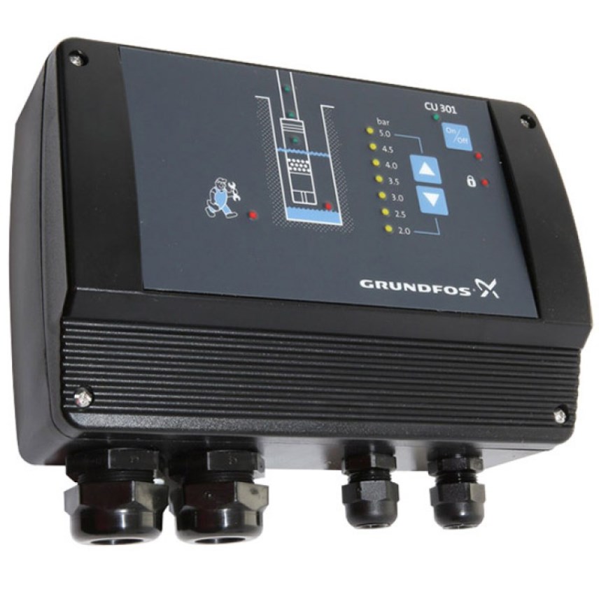
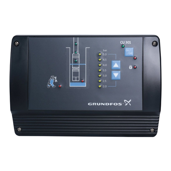
Что может блок управления CU 301
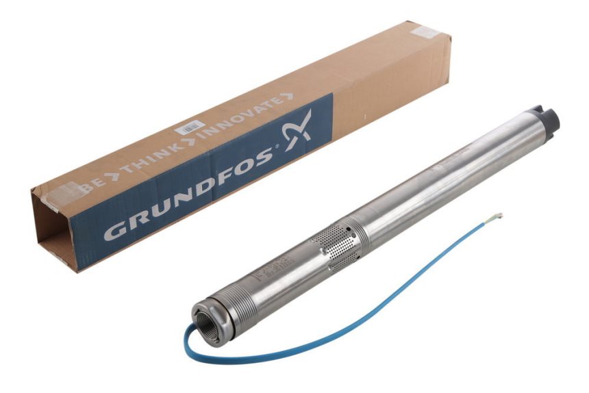
Блок управления CU 301 разработан специально для того, чтобы использовать его со скважинными насосами Grundfos SQE.
Применение устройства дает возможность, в частности:
- стабилизировать давление воды, даже если изменяется водоотбор;
- задавать величину давления воды;
- отслеживать главные показатели работы оборудования и отображать их на панели.
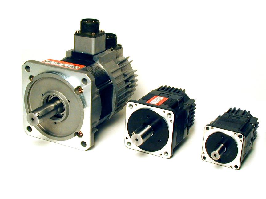
Насосы Grundfos SQE комплектуются, как правило, электромоторами MSE 3. В них заложена способность изменять обороты в границах от 65 до 100 % своих технических возможностей. В результате это позволяет выбирать в этих пределах показатели расхода и давления в любой точке отбора.
Блок управления CU 301 дает возможность так варьировать обороты двигателя насоса, чтобы водяное давление в сети не менялось даже при непостоянном водопотреблении.
[info]Устройство CU 301 не предназначено для управления насосами модели SQ! Более того, подключать его к таким насосам запрещено![/info]
С подключением и подготовкой к работе блока управления CU 301, в принципе, легко справится и непрофессиональный пользователь. Потому что производитель позаботился об идеальном совмещении устройств без дополнительной настройки и лишних органов управления. Поэтому работа системы будет простой и стабильной.
Блок управления CU 301 может входить в состав комплекта насоса Grundfos SQE. Распаковку такого насоса можно увидеть на следующем видео:
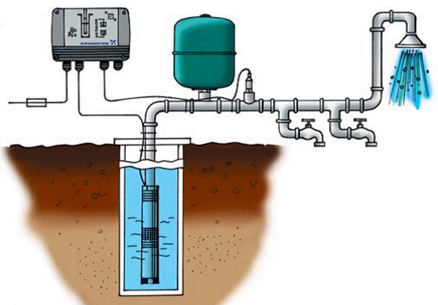
Блок управления CU 301: принцип действия и подготовка к работе
Блок управления CU 301 не нуждается в отдельном кабеле для связи с насосом: она реализована через обычный сетевой шнур.
Чтобы блок в связке с насосом работали нормально, нужно подсоединить внешний датчик давления и гидроаккумулятор хотя бы небольшой емкости. Устанавливать блок управления надо в сухом месте. И, как правило, неподалеку от смонтированного на трубопроводе гидроаккумулятора и датчика. Блок с датчиком рекомендуется разместить в непосредственной близости друг к другу либо использовать для соединения экранированный кабель.
Датчик снимает показатели и отсылает их управляющему устройству. Контроллер сопоставляет их с введенной пользователем величиной. И плавно регулирует обороты электродвигателя. В результате удается:
- поддерживать стабильное давление воды;
- по желанию пользователя легко регулировать давление в границах развиваемой насосом мощности;
- снижать расход электроэнергии за счет небольших оборотов двигателя при малом водоразборе.
Блок управления включает насос, если возникают следующие ситуации:
- Во-первых, если давление воды в системе снижается быстрее, чем на 0,1 бар/с. Чем больше вместимость гидроаккумулятора, тем медленнее падает давление. Так, при установке емкости на 8 л давление упадет на 0,1 бар/с при расходе воды от 0,18 м³/ч. Если объем бака будет больше, давление при том же расходе снизится слабее.
- Во-вторых, если давление в сети стало на 0,5 бар меньше заданного. Блок управления регулирует интенсивность работы насоса, поддерживая заданное давление в интервалах ±0,2 бар. Но если расход изменяется резко и скачкообразно, показатель давления может кратковременно колебаться в больших пределах. Это нормально и не является неисправностью.
Когда отбор воды прекращается, блок управления плавно уменьшает обороты двигателя насоса. В то же время контролируя давление в системе. Если давление превысило заданное на 0,5 бар, и снижения его не происходит, устройство отключает насос.
Пределы регулировки блока CU 301 по давлению: в интервале 2 – 5 бар (с шагом 0,5 бар);
Пределы регулировки блока CU 301 по оборотам двигателя: в интервале 7000 – 10700 об/мин.
Читайте также: Какой скважинный насос выбрать
Регистрация и диагностика неисправностей
Блок реагирует, в частности, на такие ошибки и сбои в работе системы:
- отсутствие питания в сети;
- повышенное напряжение;
- перегрев;
- перегрузку;
- выход из строя датчика давления;
- прекращение связи с насосом;
- сухой ход;
- снижение производительности насоса.
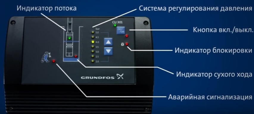
Непосредственно на панель управления выводится только сигнал о работе всухую. Другие ошибки вызывают включение индикатора «Сервис». Уточнить, по какой именно причине он сработал, можно по горящему светодиодному указателю на плате питания. Возможные варианты приведены в руководстве по эксплуатации. Доступ к плате питания открывается при снятой панели управления. Как бы то ни было, блок управления в автоматическом режиме включит насос спустя 5 минут после сбоя в работе. Время перезапуска можно задать при помощи пульта дистанционного управления R100.
Читайте также: Тонкости установки скважинного насоса Grundfos
Пульт дистанционного управления R100
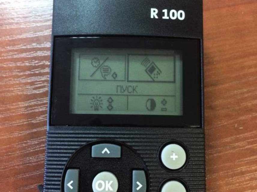
Подключение пульта дистанционного управления предоставляет блоку новые расширенные функции. Например, есть возможность изменить показатели напряжения, силы тока и параметров сигнала от датчика давления. Более того, можно узнать потребление энергии, частоту оборотов двигателя, срок его работы и количество запусков. А также задать параметры включения защиты от сухого хода, и т.д. Но блок управления может работать и без пульта.
Нажмите, на одну из кнопок, чтобы мы могли узнать понравилась вам статья или нет.
- Manuals
- Brands
- Grundfos Manuals
- Water Pump
- CU 301
- Installer manual
-
Contents
-
Table of Contents
-
Bookmarks
Quick Links
GRUNDFOS INSTRUCTIONS
CU 301
Installer’s manual
Related Manuals for Grundfos CU 301
Summary of Contents for Grundfos CU 301
-
Page 1
GRUNDFOS INSTRUCTIONS CU 301 Installer’s manual… -
Page 2: Table Of Contents
Menu INSTALLATION 5.3.1 Sensor 5.3.2 Choice of sensor 5.3.3 Maximum pressure setting 5.3.4 Automatic restart 5.3.5 Dry-running stop 5.3.6 Maximum speed 5.3.7 Buttons on CU 301 5.3.8 Indication of pump operation 5.3.9 Number Fault finding Service Technical data Electrical connection 7.1.1 Mains supply…
-
Page 3: Constant-Pressure Control
Pressure sensor SQE pump 1.2 Function The pressure is registered by means of the pressure sensor, which transmits a signal to the CU 301. The CU 301 adjusts the pump performance accordingly by changing the pump speed. Mains borne signalling: The communication between the CU 301 and the pump is effected via the power supply cable.
-
Page 4
Flow detection: During pump operation, i.e. when water is con- sumed, the CU 301 will adjust the pump speed to maintain a constant pressure. In order to stop the pump when no water is consumed, the CU 301 per- forms flow detection every 10 seconds. -
Page 5: System Sizing
Q = 0 m³/h, important that the pump is of the right type. Pump type 3,000 min 10,700 min During operation, the CU 301 controls the pump speed within the range from 3,000 min to 10,700 [m] / [feet] [m] / [feet] , see fig.
-
Page 6: Positioning The Pressure Sensor
Example: A person is in the shower. Tap 2 is opened. The increased flow will cause pressure loss in the pipe, and even though the CU 301 is keeping the pressure constant at the pressure sensor, the person in the shower will feel the pressure loss.
-
Page 7: Operating Functions
The CU 301 is communicat- 2.3 Pressure setting flashing. ing with the R100. The two arrow buttons on the CU 301 front are used for the pressure setting, see fig. 10. * If the on/off button has been used to stop the Fig. 10 pump, this button must also be used for restarting.
-
Page 8: Button Locking
The alarm functions indicated on the Setting range: 2, 2.5 … 5.0 bar. CU 301 front are described in the following sections. Arrow-up button: 3.1 Service alarm When this button is pressed, the system pressure If one or more factory-set alarm values are exceed- setting is increased in steps of 0.5 bar.
-
Page 9: Dry-Running Protection
3.2 Dry-running protection The purpose of the dry-running protection is to pro- tect the pump in case of insufficient water flow. The dry-running protection makes the conventional dry-running protection unnecessary. No additional cables to the motor are required. The dry-running protection will be active after 30 seconds’…
-
Page 10: Position Of Leds And Fuse
• Permanent red light when the supply voltage is out of range, see section 7. Technical data. • No contact to pump *) • Permanent red light when communication between the CU 301 and the pump is impossible. *) Press the on/off button to reset the alarm indication.
-
Page 11: Cu 301 With R100
The R100 communicates via infra-red light. During communication, there must be visual contact be- tween the CU 301 and the R100. The best visual contact between the two units is obtained by pointing the R100 at the lower arrow button or by removing the front cover and pointing the R100 at the right side of the CU 301, see fig.
-
Page 12
Fig. 16… -
Page 14: Menu Operation
5.1 Menu OPERATION 5.1.3 Alarm The OPERATION menu for the CU 301 offers the possibility of setting and reading operating parame- ters. Factory settings are marked in bold-faced type under each individual display. 5.1.1 Pressure setting This display shows the types of alarm that may occur.
-
Page 15: Menu Status
5.2 Menu STATUS 5.2.3 Speed The STATUS menu for the CU 301 provides operat- ing data about pump/motor and sensor. It is not pos- sible to change or set values in this menu. When [OK] is pressed continuously in this display, the displayed value is being updated.
-
Page 16: Operating Hours And Number Of Starts
4-20 mA, 0-10 V, 2-10 V. The setting of this display overrules the possibility of • Setting range unit: bar, psi. using the arrow button on the CU 301 front to in- Setting range, bar: crease the pressure to a setting above the “Maxi- •…
-
Page 17: Automatic Restart
680 W. • Motor type 1.1 to 1.73 kW, dry-running stop = 800 W. The buttons on the CU 301 can be set to: When the dry-running protection is to be active, the • Active. minimum value of the pump power input must be set •…
-
Page 18: Indication Of Pump Operation
Setting range: “–” (not active), 1, 2, … 64. Once a number setting has been made, the factory setting (not active) is no longer available. If the CU 301 and the pump do not have the same number, the alarm “No contact to pump” will be indi- cated.
-
Page 19: Fault Finding
• No contact to pump. To identify the cause of the service alarm, it is necessary to remove the front cover from the CU 301. Fit the front cover as shown in fig. 18 to avoid disconnecting the multi-core cable.
-
Page 20
If the pump has not started yet, proceed as follows: • Press the on/off button for 5 seconds. If the pump starts, the CU 301 or the sensor may be defective. Note: The pressure is not controlled and may rise to a high level. -
Page 21
12-14 inches or rewire using shielded cable. e) The CU 301 com- Are the three CU 301 supply board LEDs in pos. 2, 3 and 4 on munication part is and is the control indicator LED flashing? See section 4. Posi- defective. -
Page 22
The voltage drop Replace the pump cable. in the pump ca- ble is too big. 10. The CU 301 in- Speed reduction is activated so as to maintain a reduced performance. dicates “Speed a) The pump is worn The pump must be serviced. -
Page 23: Technical Data
Yes: The total load of 24 VDC from terminal 5 is above 100 mA. Disconnect the sensor in order to determine if it is defective. Replace defective sensor. No: The load is OK, but the CU 301 sensor input may be defec- tive. 14. The pump is a) No communica- Check that the LED “No contact to pump”…
-
Page 24: Electrical Connection
CU 301 must be connected in accordance with the local rules and standards in force for the application in question. The on/off button on the CU 301 must not be used as a safety switch when installing and servicing the pump.
-
Page 25: Mains Supply
Fig. 20 POWER PUMP Legend: 7.1.2 Pump supply PUMP, terminals 3, 4 and PE: Pos. Description Connect terminals 3 and 4 to the phase and neutral leads of the pump. Each terminal can be connected Standard pressure sensor. to any of the two leads. + 24 VDC, brown lead, terminal 5.
-
Page 27
Jebel Ali Free Zone Co. Ltd. Poland Dubai Indonesia 22 Floor, Xin Hua Lian Building GRUNDFOS Pompy Sp. z o.o. Phone: +971-4- 8815 166 PT GRUNDFOS Pompa 755-775 Huai Hai Rd, (M) ul. Klonowa 23 Telefax: +971-4-8815 136 Jl. Rawa Sumur III, Blok III/CC-1 Shanghai 200020 Baranowo k. -
Page 28
Being responsible is our foundation Thinking ahead makes it possible Innovation is the essence V7157770 0205 Repl. V7157770 0200 www.grundfos.com…