- Manuals
- Brands
- Martel Manuals
- Test Equipment
- BETAGAUGE 330
- Reference manual
-
Contents
-
Table of Contents
-
Bookmarks
Quick Links
BETAGAUGE 330
Reference Manual
Related Manuals for Martel BETAGAUGE 330
Summary of Contents for Martel BETAGAUGE 330
-
Page 1
BETAGAUGE 330 Reference Manual… -
Page 2: Table Of Contents
1.1 Contacting Martel / Beta ……..1…
-
Page 3: Introduction
1. Introduction The BetaGauge 330 is designed to be a simple to use yet very versatile pressure calibrator. Its internal pressure sensor combined with an innovative electrically powered pump along with inputs for mA, voltage, switch contacts and an RTD probe allow the 330 to calibrate virtually any pressure device.
-
Page 4
Symbol Description Electric Shock Fuse PE Ground Hot Surface (Burn Hazard) Read the User’s Manual (Important Information) Canadian Standards Association The following definitions apply to the terms “Warning” and “Caution”. • “Warning” identifies conditions and actions that may pose hazards to the user. •… -
Page 5
• Do not use the calibrator if it operates abnormally. Protection may be impaired. When in doubt, have the calibrator serviced. • Do not operate the calibrator around explosive gas, vapor, or dust. • When measuring pressure, make sure the process pressure line is shut off and depressurized before you connect it or disconnect it from the pressure module. -
Page 6: Calibrator Interface
2. Calibrator Interface Figure 1 shows the location of the pressure controls, connection port and electrical inputs. Figure 1…
-
Page 7
Figures 2A and 2B show the location of the keys. Table 2 describes the function of each key. Figure 2A Keypad (Electric Pump Versions) Table 2 Key Functions Name Description Function Keys These are soft keys used to configure the calibrator ON/OFF Key This key is used to turn the calibrator on and off ZERO Key… -
Page 8: Calibrator Display
2.1 Calibrator Display The Calibrator Display consists of two regions: The menu bar (located along the bottom of the screen) is used to access a menu system. The main display (the rest) consists of up to three process measurement sub-regions. These sub-regions will henceforth be referred to as the UPPER, MIDDLE and LOWER displays.
-
Page 9
2.1.2.1 Setting the Active Display The active display is indicated by the center option on the Main Menu, pressing the F2 key will toggle the active display. 2.1.2.2 Setting Active Display Parameters To set the parameters of the active display use the CONFIG option to get to the Display Configuration Menu. -
Page 10: Using The Backlight
Table 4 Mode Concurrency CURRENT DISPLAY P[1] [EXT] P[1] [EXT] Volts Loop P[1] [EXT] P[1]ST [EXT]ST mA Loop Volts X = Not a valid mode 2.1.1.3 Accessing Other Menus Use the MORE option on the Main Menu to access the other menu functions. 2.2 Using the Backlight The backlight is controlled by the LIGHT softkey on the main menu on the models with electric pump.
-
Page 11: Other Menu Controlled Functions
2.4 Other Menu Controlled Functions There are 12 ‘sub-main’ menus that can be accessed through the MORE option of the Main Menu. A ‘sub-main’ menu contains three options. The first option is unique to the function. The second and third options of a ‘sub-main’ menu are always the same. The NEXT option leads to the next ‘sub-main’…
-
Page 12
Figure 4 Menu Map… -
Page 13
If SAVE or RECALL is selected use the arrow keys to select the set-up location. Then use the save option to store the current set-up into the selected location or the recall option to recall the set-up stored in the selected location. The display menu will automatically go home. -
Page 14: Initial Setup And Basic Pressure Generation
When in this mode use the arrow keys to set the maximum pressure. 2.4.9 HART™ Resistor An internal 250 ohm HART Resistor can be enabled when the BetaGauge 330 is operated in the “mA Measure-24V” mode. This allows a HART Communicator to be connected across the mA terminals and eliminates the need for adding an external resistor.
-
Page 15
3.1 Electric Pump Considerations The BetaGauge 330-30 and 330-150 incorporate a small, lightweight, battery powered pneumatic pump that allows the user, in the case of the 330-150 to build relatively high pressure up to 150psi (10Bar) quickly and with good control. -
Page 16: Measuring Pressure
See section 2.3. 4.1 Media Compatibility The BetaGauge 330 feature a unique user accessible valve cleaning port to facilitate servicing the pump. Section 16.3 shows how to clean these valves. Even though servicing the pump is easy, care should be taken to only expose the calibrator to clean, dry gases.
-
Page 17: Measuring Current
Figure 6 5. Measuring and Generating Current (4 to 20 mA) 1. To measure current use the input terminals in the front of the calibrator. Select the mA function on the lower display. Current is measured in mA and percentage of range. The range on the calibrator is set to 0% at 4 mA and 100% at 20 mA.
-
Page 18
Figure 7-1 Figure 7-2 Figure 7-3 Figure 7-4… -
Page 19: Measuring Voltage
1/4” diameter stainless steel sheath. Note: The factory default type is PT100-385 so if the 330 is being used with the Martel Model LPT100A probe you do not have to set the probe type. Simply plug the probe into the 330 and configure the display to read temperature.
-
Page 20: Performing A Pressure Switch Test
Figure 9 8. Performing a Pressure Switch Test Figure 10 To perform a switch test, follow these steps: 1. Change the setup to Setup 4 (default switch test). Setup 4: The upper display is set to [P1] ST, all other displays are off. Important NOTE: The pressure Switch Test can be performed with the following functions[P1] ST, or EXT ST.
-
Page 21
3. Make sure the vent on the pump is open. Zero the calibrator if necessary. Close the vent after zeroing the calibrator. 4. The top of the display will read “CLOSE”. 5. Apply pressure with the pump slowly until the switch opens. Important NOTE: In the switch test mode the display update rate is increased to help capture changing pressure inputs. -
Page 22: Calibrating Transmitters
9. Press the “NEW TEST” option to clear the data and perform another test. 10. Press the “DONE” option to end the test and return to the standard pressure setting. Example: [P1] ST will return to [P1]. Important NOTE: The previous example uses a normally closed switch. The basic procedure is still the same for a normally open switch, the display will just read “OPEN”…
-
Page 23: Calibrating A Pressure-To-Current Transmitter
9.2 Calibrating a Pressure-to-Current Transmitter To calibrate a pressure-to-current transmitter (P/I), perform the following steps: 1. Connect the calibrator and the pump to the transmitter. 2. Apply pressure with the pump. 3. Measure the current output of the transmitter. 4. Ensure the reading is correct. If not, adjust the transmitter as necessary. Figure 11.
-
Page 24: Percent Error Function
9.3 Percent Error Function The calibrator features a unique function which can calculate pressure vs. milliamp error as a percentage of the 4 to 20 mA loop span. The percent error mode uses all 3 screens and has a unique menu structure. It simultaneously displays pressure, mA and percent error.
-
Page 25
4. LOOP POWER can be toggled on/off, select NEXT when done. 5. Use SELECT to toggle through the UNIT options, and select NEXT to move on. 6. Use the arrow keys to set the 100% point of the desired pressure range, select DONE SET when finished. -
Page 26: Minimum And Maximum Storage Capability
Note: The 0% and 100% point will be saved in non-volatile memory until they are changed again by the user for the internal sensors, and external pressure modules. When using an external module the 0% and 100% are set to low and full scale of the module until the user changes it, or if it was previously saved.
-
Page 27: Factory Setups
11. Factory Setups The Calibrator is loaded with five factory commonly used setups. These setups are shown below. Note: Any of these setups can be changed and saved by the user. Setup 1: The upper display is set to [P1] mode and the lower is set to mA, middle is off. Setup 2: The upper display is set to [P1] mode and the lower is set to RTD, middle is off.
-
Page 28: Custody Transfer / Flow Calibration
NOTE: To use the remote control option a custom RS-232 cable must be purchased from Martel (LEM232). To contact Martel refer to Section 1.1 of this manual. With this connection the user can write programs on the…
-
Page 29: Setting Up The Rs-232 Port For Remote Control
terminal, such as Hyper Terminal, to enter single commands. Typical RS-232 remote configurations are shown in Figure 13. Figure 13. Calibrator-to-Computer Connection 13.2 Setting up the RS-232 Port for Remote Control Note: The RS-232 connection cable should not exceed 15m unless the load capacitance measured at connection points is less than 2500pF.
-
Page 30: Changing Between Remote And Local Operation
5. Select ASCII setup from File/Properties/Settings and mark these choices: Echo typed characters locally Wrap lines that exceed terminal width 6. Select Ok 7. To see if the port works enter *IDN?. This command will return information on the calibrator. 13.3 Changing Between Remote and Local Operation There are three modes of operation of the calibrator, Local, Remote, and Remote with Lockout.
-
Page 31
Compound Commands Commands that contain more than one command on one line. For example; RTD_TYPE PT385_100;RTD_TYPE? Sets the calibrator to RTD type PT385_100 and queries it to verify. It will return: PT385_100 13.4.2 Character Processing The data entered into the calibrator is processed as follows: •… -
Page 32
13.4.4 Calibrator Status Error Queue If an error occurs due to invalid input or buffer overflow, its error code is sent to the error queue. The error code can be read from the queue with the command FAULT?. The error queue holds 15 error codes. -
Page 33: Remote Commands And Error Codes
13.5 Remote Commands and Error Codes The following tables list all commands, and their descriptions, that are accepted by the calibrator. Table 5: Common Commands Command Description *CLS (Clear status.) Clears the error queue. *IDN? Identification query. Returns the manufacturer, model number, and firmware revision level of the Calibrator.
-
Page 34
IO_STATE Set the calibrator’s mA state. IO_STATE? Return the calibrator’s mA state. LOCAL Returns user to manual operation of the calibrator LOCKOUT Locks out the keypad of the calibrator in remote operation LO_ERR Sets the 0% of span limit for percent error mode LO_ERR Returns the 0% of span limit for percent error mode MOTOR_ON… -
Page 35
LOWER Designates Lower display Milliamps of current MEASURE Measure state MEAS_LOOP Measure with loop power state MIDDLE Designates Middle display Resistance in ohms PCT_ERR Percent Error PERCENT Percent PT385_100 100 Ohm 385 Platinum RTD type PT392_100 100 Ohm 392 Platinum RTD type PTJIS_100 100 Ohm JIS Platinum RTD type P1 pressure measurement function… -
Page 36: Entering Commands
13.6 Entering Commands Commands for the calibrator may be entered in upper or lower case. There is at least one space required between the command and parameter, all other spaces are optional. Almost all commands for the calibrator are sequential; any overlapped commands will be indicated as such.
-
Page 37
CPRT_COEFC This command is used for entering a custom RTD into the calibrator. The numeric value entered after the command will be set as the first coefficient of the polynomial used by the custom RTD. For example: CPRT_COEFC –4.183000E-12 enters –4.183000E-12 as coefficient C. CPRT_COEFC? Returns the number that was entered for the third coefficient of the polynomial used in the custom RTD. -
Page 38
If you send DISPLAY? It will return ON, ON, ON if the all the displays are on. FAULT? Returns the error code number of an error that has occurred. The command may be entered when the previous command did not do what it was meant to do. For example, if a value for current output is entered that is bigger than the supported range (0-24mA) FAULT? Would return: 103 which is the code number for an entry over range. -
Page 39
If you send ERROR _PORT?, it will return P1 if the pressure port in percent error is [P1]. FUNC Sets the display indicated in argument one to the function indicated in argument 2. For example: To set the lower display to RTD mode send FUNC LOWER,RTD. FUNC? Returns the current mode of all displays. -
Page 40
IO_STATE? Returns the input/output/simulate state of the mA function of the calibrator. For example: If the calibrator was in mA simulate mode IO_STATE? Would return SIM. LOCAL Restores the calibrator to local operation if it was in remote mode. Also clears LOCKOUT if the calibrator was in lockout mode. -
Page 41
For example: If when measuring a P100-385 at 0 degrees cel sending OHMS? would return 1.000000E+02, OHM . This command also switches the calibrator into mA output mode. A number and a unit must be entered after the command. For example: OUT 5 MA sets the current output at 5 mA OUT? Returns the output of the calibrator. -
Page 42
PT385_100; PT392_100; PTJIS_100; CUSTOM; For Example: RTD_TYPE PT385_100 sets RTD type to PT100-385 RTD_TYPE? Returns the RTD type. For Example: If the RTD type is PT385_100, RTD_TYPE? Will return PT100_385. Sets the output for current simulation. This command also switches the calibrator into mA simulation mode. -
Page 43
TEMP_UNIT? Returns the temperature unit, (CEL or FAR) used when measuring RTDs for each of the 3 displays. VAL? Returns the value of any measurement taking place on the upper and lower display. For example, if the upper display is measuring 5mA, and the lower display is measuring 10V, then VAL? will return: 5.000000E-03, A, 1.000000E+01, V ZERO_MEAS… -
Page 44: Specifications
14. Specifications (15 °C to 35 °C unless otherwise noted.) General Instrument Setup Recall 5; last used on power-up Environmental Operating Temperature -10 °C to +50 °C Storage Temperature -20 °C to +60 °C Power Requirements 12 VDC Battery Eight (8) AA alkaline, Lithium or NiMh cells Physical Dimensions 8”…
-
Page 45: Warranty
You can also call 1-800-821-0023 to have a form faxed. Martel will not be responsible for damage as a result of poor return packaging. Out of warranty repairs and recalibration will be subject to specific charges.
-
Page 46: Service Center Calibration Or Repair
6. Clean the o-ring assembly and the o-ring on the retention caps with IPA and inspect the o-rings closely for any damage or excessive wear. Replacements are included in the repair kit, if needed. 7. Inspect the springs for wear or loss of tension. They should be approximately 8.6 mm long in the relaxed state.
-
Page 47
BetaGauge 330 Ranges and Resolutions Range (PSI) 30 PSI / 2.0 Bar 150 PSI / 10 Bar 300 PSI / 20 Bar Burst Pressure (PSI) 2000 Proof Pressure (PSI) Engineering Unit Factor 30.000 150.00 300.00 0.06894757 2.0684 10.3421 20.684 mbar 68.94757… -
Page 48
Tel: (603) 434-1433 800-821-0023 Fax: (603) 434-1653 Martel Electronics 3 Corporate Park Dr. Derry, NH 03038 8/10 Rev E 0219782…
-
Page 1
BETAGAUGE 330 Reference Manual… -
Page 2: Table Of Contents
1.1 Contacting Martel / Beta ……..1…
-
Page 3: Introduction
1. Introduction The BetaGauge 330 is designed to be a simple to use yet very versatile pressure calibrator. Its internal pressure sensor combined with an innovative electrically powered pump along with inputs for mA, voltage, switch contacts and an RTD probe allow the 330 to calibrate virtually any pressure device.
-
Page 4
Symbol Description Electric Shock Fuse PE Ground Hot Surface (Burn Hazard) Read the User’s Manual (Important Information) Canadian Standards Association The following definitions apply to the terms “Warning” and “Caution”. • “Warning” identifies conditions and actions that may pose hazards to the user. •… -
Page 5
• Do not use the calibrator if it operates abnormally. Protection may be impaired. When in doubt, have the calibrator serviced. • Do not operate the calibrator around explosive gas, vapor, or dust. • When measuring pressure, make sure the process pressure line is shut off and depressurized before you connect it or disconnect it from the pressure module. -
Page 6: Calibrator Interface
2. Calibrator Interface Figure 1 shows the location of the pressure controls, connection port and electrical inputs. Figure 1…
-
Page 7
Figures 2A and 2B show the location of the keys. Table 2 describes the function of each key. Figure 2A Keypad (Electric Pump Versions) Table 2 Key Functions Name Description Function Keys These are soft keys used to configure the calibrator ON/OFF Key This key is used to turn the calibrator on and off ZERO Key… -
Page 8: Calibrator Display
2.1 Calibrator Display The Calibrator Display consists of two regions: The menu bar (located along the bottom of the screen) is used to access a menu system. The main display (the rest) consists of up to three process measurement sub-regions. These sub-regions will henceforth be referred to as the UPPER, MIDDLE and LOWER displays.
-
Page 9
2.1.2.1 Setting the Active Display The active display is indicated by the center option on the Main Menu, pressing the F2 key will toggle the active display. 2.1.2.2 Setting Active Display Parameters To set the parameters of the active display use the CONFIG option to get to the Display Configuration Menu. -
Page 10: Using The Backlight
Table 4 Mode Concurrency CURRENT DISPLAY P[1] [EXT] P[1] [EXT] Volts Loop P[1] [EXT] P[1]ST [EXT]ST mA Loop Volts X = Not a valid mode 2.1.1.3 Accessing Other Menus Use the MORE option on the Main Menu to access the other menu functions. 2.2 Using the Backlight The backlight is controlled by the LIGHT softkey on the main menu on the models with electric pump.
-
Page 11: Other Menu Controlled Functions
2.4 Other Menu Controlled Functions There are 12 ‘sub-main’ menus that can be accessed through the MORE option of the Main Menu. A ‘sub-main’ menu contains three options. The first option is unique to the function. The second and third options of a ‘sub-main’ menu are always the same. The NEXT option leads to the next ‘sub-main’…
-
Page 12
Figure 4 Menu Map… -
Page 13
If SAVE or RECALL is selected use the arrow keys to select the set-up location. Then use the save option to store the current set-up into the selected location or the recall option to recall the set-up stored in the selected location. The display menu will automatically go home. -
Page 14: Initial Setup And Basic Pressure Generation
When in this mode use the arrow keys to set the maximum pressure. 2.4.9 HART™ Resistor An internal 250 ohm HART Resistor can be enabled when the BetaGauge 330 is operated in the “mA Measure-24V” mode. This allows a HART Communicator to be connected across the mA terminals and eliminates the need for adding an external resistor.
-
Page 15
3.1 Electric Pump Considerations The BetaGauge 330-30 and 330-150 incorporate a small, lightweight, battery powered pneumatic pump that allows the user, in the case of the 330-150 to build relatively high pressure up to 150psi (10Bar) quickly and with good control. -
Page 16: Measuring Pressure
See section 2.3. 4.1 Media Compatibility The BetaGauge 330 feature a unique user accessible valve cleaning port to facilitate servicing the pump. Section 16.3 shows how to clean these valves. Even though servicing the pump is easy, care should be taken to only expose the calibrator to clean, dry gases.
-
Page 17: Measuring Current
Figure 6 5. Measuring and Generating Current (4 to 20 mA) 1. To measure current use the input terminals in the front of the calibrator. Select the mA function on the lower display. Current is measured in mA and percentage of range. The range on the calibrator is set to 0% at 4 mA and 100% at 20 mA.
-
Page 18
Figure 7-1 Figure 7-2 Figure 7-3 Figure 7-4… -
Page 19: Measuring Voltage
1/4” diameter stainless steel sheath. Note: The factory default type is PT100-385 so if the 330 is being used with the Martel Model LPT100A probe you do not have to set the probe type. Simply plug the probe into the 330 and configure the display to read temperature.
-
Page 20: Performing A Pressure Switch Test
Figure 9 8. Performing a Pressure Switch Test Figure 10 To perform a switch test, follow these steps: 1. Change the setup to Setup 4 (default switch test). Setup 4: The upper display is set to [P1] ST, all other displays are off. Important NOTE: The pressure Switch Test can be performed with the following functions[P1] ST, or EXT ST.
-
Page 21
3. Make sure the vent on the pump is open. Zero the calibrator if necessary. Close the vent after zeroing the calibrator. 4. The top of the display will read “CLOSE”. 5. Apply pressure with the pump slowly until the switch opens. Important NOTE: In the switch test mode the display update rate is increased to help capture changing pressure inputs. -
Page 22: Calibrating Transmitters
9. Press the “NEW TEST” option to clear the data and perform another test. 10. Press the “DONE” option to end the test and return to the standard pressure setting. Example: [P1] ST will return to [P1]. Important NOTE: The previous example uses a normally closed switch. The basic procedure is still the same for a normally open switch, the display will just read “OPEN”…
-
Page 23: Calibrating A Pressure-To-Current Transmitter
9.2 Calibrating a Pressure-to-Current Transmitter To calibrate a pressure-to-current transmitter (P/I), perform the following steps: 1. Connect the calibrator and the pump to the transmitter. 2. Apply pressure with the pump. 3. Measure the current output of the transmitter. 4. Ensure the reading is correct. If not, adjust the transmitter as necessary. Figure 11.
-
Page 24: Percent Error Function
9.3 Percent Error Function The calibrator features a unique function which can calculate pressure vs. milliamp error as a percentage of the 4 to 20 mA loop span. The percent error mode uses all 3 screens and has a unique menu structure. It simultaneously displays pressure, mA and percent error.
-
Page 25
4. LOOP POWER can be toggled on/off, select NEXT when done. 5. Use SELECT to toggle through the UNIT options, and select NEXT to move on. 6. Use the arrow keys to set the 100% point of the desired pressure range, select DONE SET when finished. -
Page 26: Minimum And Maximum Storage Capability
Note: The 0% and 100% point will be saved in non-volatile memory until they are changed again by the user for the internal sensors, and external pressure modules. When using an external module the 0% and 100% are set to low and full scale of the module until the user changes it, or if it was previously saved.
-
Page 27: Factory Setups
11. Factory Setups The Calibrator is loaded with five factory commonly used setups. These setups are shown below. Note: Any of these setups can be changed and saved by the user. Setup 1: The upper display is set to [P1] mode and the lower is set to mA, middle is off. Setup 2: The upper display is set to [P1] mode and the lower is set to RTD, middle is off.
-
Page 28: Custody Transfer / Flow Calibration
NOTE: To use the remote control option a custom RS-232 cable must be purchased from Martel (LEM232). To contact Martel refer to Section 1.1 of this manual. With this connection the user can write programs on the…
-
Page 29: Setting Up The Rs-232 Port For Remote Control
terminal, such as Hyper Terminal, to enter single commands. Typical RS-232 remote configurations are shown in Figure 13. Figure 13. Calibrator-to-Computer Connection 13.2 Setting up the RS-232 Port for Remote Control Note: The RS-232 connection cable should not exceed 15m unless the load capacitance measured at connection points is less than 2500pF.
-
Page 30: Changing Between Remote And Local Operation
5. Select ASCII setup from File/Properties/Settings and mark these choices: Echo typed characters locally Wrap lines that exceed terminal width 6. Select Ok 7. To see if the port works enter *IDN?. This command will return information on the calibrator. 13.3 Changing Between Remote and Local Operation There are three modes of operation of the calibrator, Local, Remote, and Remote with Lockout.
-
Page 31
Compound Commands Commands that contain more than one command on one line. For example; RTD_TYPE PT385_100;RTD_TYPE? Sets the calibrator to RTD type PT385_100 and queries it to verify. It will return: PT385_100 13.4.2 Character Processing The data entered into the calibrator is processed as follows: •… -
Page 32
13.4.4 Calibrator Status Error Queue If an error occurs due to invalid input or buffer overflow, its error code is sent to the error queue. The error code can be read from the queue with the command FAULT?. The error queue holds 15 error codes. -
Page 33: Remote Commands And Error Codes
13.5 Remote Commands and Error Codes The following tables list all commands, and their descriptions, that are accepted by the calibrator. Table 5: Common Commands Command Description *CLS (Clear status.) Clears the error queue. *IDN? Identification query. Returns the manufacturer, model number, and firmware revision level of the Calibrator.
-
Page 34
IO_STATE Set the calibrator’s mA state. IO_STATE? Return the calibrator’s mA state. LOCAL Returns user to manual operation of the calibrator LOCKOUT Locks out the keypad of the calibrator in remote operation LO_ERR Sets the 0% of span limit for percent error mode LO_ERR Returns the 0% of span limit for percent error mode MOTOR_ON… -
Page 35
LOWER Designates Lower display Milliamps of current MEASURE Measure state MEAS_LOOP Measure with loop power state MIDDLE Designates Middle display Resistance in ohms PCT_ERR Percent Error PERCENT Percent PT385_100 100 Ohm 385 Platinum RTD type PT392_100 100 Ohm 392 Platinum RTD type PTJIS_100 100 Ohm JIS Platinum RTD type P1 pressure measurement function… -
Page 36: Entering Commands
13.6 Entering Commands Commands for the calibrator may be entered in upper or lower case. There is at least one space required between the command and parameter, all other spaces are optional. Almost all commands for the calibrator are sequential; any overlapped commands will be indicated as such.
-
Page 37
CPRT_COEFC This command is used for entering a custom RTD into the calibrator. The numeric value entered after the command will be set as the first coefficient of the polynomial used by the custom RTD. For example: CPRT_COEFC –4.183000E-12 enters –4.183000E-12 as coefficient C. CPRT_COEFC? Returns the number that was entered for the third coefficient of the polynomial used in the custom RTD. -
Page 38
If you send DISPLAY? It will return ON, ON, ON if the all the displays are on. FAULT? Returns the error code number of an error that has occurred. The command may be entered when the previous command did not do what it was meant to do. For example, if a value for current output is entered that is bigger than the supported range (0-24mA) FAULT? Would return: 103 which is the code number for an entry over range. -
Page 39
If you send ERROR _PORT?, it will return P1 if the pressure port in percent error is [P1]. FUNC Sets the display indicated in argument one to the function indicated in argument 2. For example: To set the lower display to RTD mode send FUNC LOWER,RTD. FUNC? Returns the current mode of all displays. -
Page 40
IO_STATE? Returns the input/output/simulate state of the mA function of the calibrator. For example: If the calibrator was in mA simulate mode IO_STATE? Would return SIM. LOCAL Restores the calibrator to local operation if it was in remote mode. Also clears LOCKOUT if the calibrator was in lockout mode. -
Page 41
For example: If when measuring a P100-385 at 0 degrees cel sending OHMS? would return 1.000000E+02, OHM . This command also switches the calibrator into mA output mode. A number and a unit must be entered after the command. For example: OUT 5 MA sets the current output at 5 mA OUT? Returns the output of the calibrator. -
Page 42
PT385_100; PT392_100; PTJIS_100; CUSTOM; For Example: RTD_TYPE PT385_100 sets RTD type to PT100-385 RTD_TYPE? Returns the RTD type. For Example: If the RTD type is PT385_100, RTD_TYPE? Will return PT100_385. Sets the output for current simulation. This command also switches the calibrator into mA simulation mode. -
Page 43
TEMP_UNIT? Returns the temperature unit, (CEL or FAR) used when measuring RTDs for each of the 3 displays. VAL? Returns the value of any measurement taking place on the upper and lower display. For example, if the upper display is measuring 5mA, and the lower display is measuring 10V, then VAL? will return: 5.000000E-03, A, 1.000000E+01, V ZERO_MEAS… -
Page 44: Specifications
14. Specifications (15 °C to 35 °C unless otherwise noted.) General Instrument Setup Recall 5; last used on power-up Environmental Operating Temperature -10 °C to +50 °C Storage Temperature -20 °C to +60 °C Power Requirements 12 VDC Battery Eight (8) AA alkaline, Lithium or NiMh cells Physical Dimensions 8”…
-
Page 45: Warranty
You can also call 1-800-821-0023 to have a form faxed. Martel will not be responsible for damage as a result of poor return packaging. Out of warranty repairs and recalibration will be subject to specific charges.
-
Page 46: Service Center Calibration Or Repair
6. Clean the o-ring assembly and the o-ring on the retention caps with IPA and inspect the o-rings closely for any damage or excessive wear. Replacements are included in the repair kit, if needed. 7. Inspect the springs for wear or loss of tension. They should be approximately 8.6 mm long in the relaxed state.
-
Page 47
BetaGauge 330 Ranges and Resolutions Range (PSI) 30 PSI / 2.0 Bar 150 PSI / 10 Bar 300 PSI / 20 Bar Burst Pressure (PSI) 2000 Proof Pressure (PSI) Engineering Unit Factor 30.000 150.00 300.00 0.06894757 2.0684 10.3421 20.684 mbar 68.94757… -
Page 48
Tel: (603) 434-1433 800-821-0023 Fax: (603) 434-1653 Martel Electronics 3 Corporate Park Dr. Derry, NH 03038 8/10 Rev E 0219782…
![]()
BETAGAUGE 330
Reference Manual
BETAGauge 330
Reference Manual
1. Introduction . . . . . . . . . . . . . . . . . . . . . . . . . . . . . . . . . . . . . . . . . . . .1
|
1.1 |
Contacting Martel / Beta . . . . . . . . . . . . . . . . . . . . . . . . . . . . . . . . . . . |
.1 |
||
|
1.2 |
Standard Equipment . . . . . . . . . . . . . . . . . . . . . . . . . . . . . . . . . . . . . . |
.1 |
||
|
1.3 |
Safety Information . . . . . . . . . . . . . . . . . . . . . . . . . . . . . . . . . . . . . . . . |
.1 |
||
|
2. |
Calibrator Interface . . . . . . . . . . . . . . . . . . . . . . . . . . . . . . . . . . . . . |
.4 |
||
|
2.1 |
Calibrator Display . . . . . . . . . . . . . . . . . . . . . . . . . . . . . . . . . . . . . . . . |
.6 |
||
|
2.2 |
Using the Backlight . . . . . . . . . . . . . . . . . . . . . . . . . . . . . . . . . . . . . . . |
.8 |
||
|
2.3 |
Using the Zero Function . . . . . . . . . . . . . . . . . . . . . . . . . . . . . . . . . . . |
.8 |
||
|
2.4 |
Other Menu Controlled Functions . . . . . . . . . . . . . . . . . . . . . . . . . . . . |
.9 |
||
|
3. |
Initial Setup and Basic Pressure Generation . . . . . . . . . . . . . . . . . . |
12 |
||
|
4. |
Measuring Pressure . . . . . . . . . . . . . . . . . . . . . . . . . . . . . . . . . . . . . |
14 |
||
|
4.1 |
Media Compatibility . . . . . . . . . . . . . . . . . . . . . . . . . . . . . . . . . . . . . . . |
14 |
||
|
4.2 |
Measuring Pressure with External Modules . . . . . . . . . . . . . . . . . . . . . |
14 |
||
|
5. |
Measuring Current . . . . . . . . . . . . . . . . . . . . . . . . . . . . . . . . . . . . . . |
15 |
||
|
6. |
Measuring Voltage . . . . . . . . . . . . . . . . . . . . . . . . . . . . . . . . . . . . . . |
17 |
||
|
7. |
Measuring Temperature with an RTD . . . . . . . . . . . . . . . . . . . . . . . |
17 |
||
|
8. |
Performing a Pressure Switch Test . . . . . . . . . . . . . . . . . . . . . . . . . |
18 |
||
|
9. |
Calibrating Transmitters . . . . . . . . . . . . . . . . . . . . . . . . . . . . . . . . . |
20 |
||
|
9.1 |
Using the mA Input Function . . . . . . . . . . . . . . . . . . . . . . . . . . . . . . . . |
20 |
||
|
9.2 |
Calibrating a Pressure-to-Current Transmitter . . . . . . . . . . . . . . . . . . . . |
21 |
||
|
9.3 |
Percent Error Function . . . . . . . . . . . . . . . . . . . . . . . . . . . . . . . . . . . . . |
22 |
||
|
10. Minimum and Maximum Storage Capability . . . . . . . . . . . . . . . . . . |
24 |
|||
|
11. Factory Setups . . . . . . . . . . . . . . . . . . . . . . . . . . . . . . . . . . . . . . . . |
25 |
|||
|
12. Custody Transfer / Flow Calibration . . . . . . . . . . . . . . . . . . . . . . . |
26 |
|||
|
13. Remote Operation . . . . . . . . . . . . . . . . . . . . . . . . . . . . . . . . . . . . . |
26 |
|||
|
13.1 |
Remote Interface . . . . . . . . . . . . . . . . . . . . . . . . . . . . . . . . . . . . . . . |
26 |
||
|
13.2 |
Setting up the RS-232 Port for Remote Control . . . . . . . . . . . . . . . . . |
27 |
||
|
13.3 |
Changing Between Remote and Local Operation . . . . . . . . . . . . . . . . |
28 |
||
|
13.4 |
Using Commands . . . . . . . . . . . . . . . . . . . . . . . . . . . . . . . . . . . . . . . |
28 |
||
|
13.5 |
Remote Commands and Error Codes . . . . . . . . . . . . . . . . . . . . . . . . |
31 |
||
|
13.6 |
Entering Commands . . . . . . . . . . . . . . . . . . . . . . . . . . . . . . . . . . . . . |
34 |
||
|
14. Specifications . . . . . . . . . . . . . . . . . . . . . . . . . . . . . . . . . . . . . . . . . |
42 |
|||
|
15. Warranty . . . . . . . . . . . . . . . . . . . . . . . . . . . . . . . . . . . . . . . . . . . . . |
43 |
|||
|
16. Maintenance . . . . . . . . . . . . . . . . . . . . . . . . . . . . . . . . . . . . . . . . . . |
43 |
|||
|
16.1 |
Replacing Batteries . . . . . . . . . . . . . . . . . . . . . . . . . . . . . . . . . . . . . . |
43 |
||
|
16.2 |
Cleaning the Unit . . . . . . . . . . . . . . . . . . . . . . . . . . . . . . . . . . . . . . . . |
43 |
||
|
16.3 |
Valve Cleaning Procedure . . . . . . . . . . . . . . . . . . . . . . . . . . . . . . . . . . |
43 |
||
|
16.4 |
Service Center Calibration or Repair . . . . . . . . . . . . . . . . . . . . . . . . . |
44 |

1. Introduction
The BetaGauge 330 is designed to be a simple to use yet very versatile pressure calibrator. Its internal pressure sensor combined with an innovative electrically powered pump along with inputs for mA, voltage, switch contacts and an RTD probe allow the 330 to calibrate virtually any pressure device. The model 330-300 uses a manual pump to reach higher pressures up to 300 psi. An external pressure module option allows an even wider range of pressure calibration options including absolute and differential.
1.1 Customer Service
Corporate Office: www.martelcorp.com
e-mail: sales@martelcorp.com
Tel: (603) 434-1433 800-821-0023 Fax: (603) 434-1653
Martel Electronics
3 Corporate Park Dr.
Derry, NH 03038
1.2 Standard Equipment
Check to see if your calibrator is complete. It should include: BetaGauge 330 Calibrator, instruction manual, test leads, calibration hose kit with fittings, carrying case, calibration certificate with data.
1.3 Safety information
Symbols Used
The following table lists the International Electrical Symbols. Some or all of these symbols may be used on the instrument or in this manual.
Symbol Description
AC (Alternating Current)
AC-DC
Battery
CE Complies with European Union Directives
DC
Double Insulated
1

Symbol Description
Electric Shock
Fuse
PE Ground
Hot Surface (Burn Hazard)
Read the User’s Manual (Important Information)
Off
On
Canadian Standards Association
The following definitions apply to the terms “Warning” and “Caution”.
•“Warning” identifies conditions and actions that may pose hazards to the user.
•“Caution” identifies conditions and actions that may damage the instrument being used.
Use the calibrator only as specified in this manual, otherwise injury and damage to the calibrator may occur.
Warning
To avoid possible electric shock or personal injury:
•Do not apply more than the rated voltage. See specifications for supported ranges.
•Follow all equipment safety procedures.
•Never touch the probe to a voltage source when the test leads are plugged into the current terminals.
•Do not use the calibrator if it is damaged. Before you use the calibrator, inspect the case. Look for cracks or missing plastic. Pay particular attention to the insulation surrounding the connectors.
•Select the proper function and range for your measurement.
•Make sure the battery cover is closed and latched before you operate the calibrator.
•Remove test leads from the calibrator before you open the battery door.
•Inspect the test leads for damaged insulation or exposed metal. Check test leads continuity. Replace damaged test leads before you use the calibrator.
•When using the probes, keep your fingers away from the probe contacts. Keep your fingers behind the finger guards on the probes.
•Connect the common test lead before you connect the live test lead. When you disconnect test leads, disconnect the live test lead first.
2
•Do not use the calibrator if it operates abnormally. Protection may be impaired. When in doubt, have the calibrator serviced.
•Do not operate the calibrator around explosive gas, vapor, or dust.
•When measuring pressure, make sure the process pressure line is shut off and depressurized before you connect it or disconnect it from the pressure module.
•Disconnect test leads before changing to another measure or source function.
•When servicing the calibrator, use only specified replacement parts.
•To avoid false readings, which could lead to possible electric shock or personal injury, replace the battery as soon as the battery indicator appears.
 Caution
To avoid possible damage to calibrator or to equipment under test:
• Use the proper jacks, function, and range for your measurement or sourcing application.
3

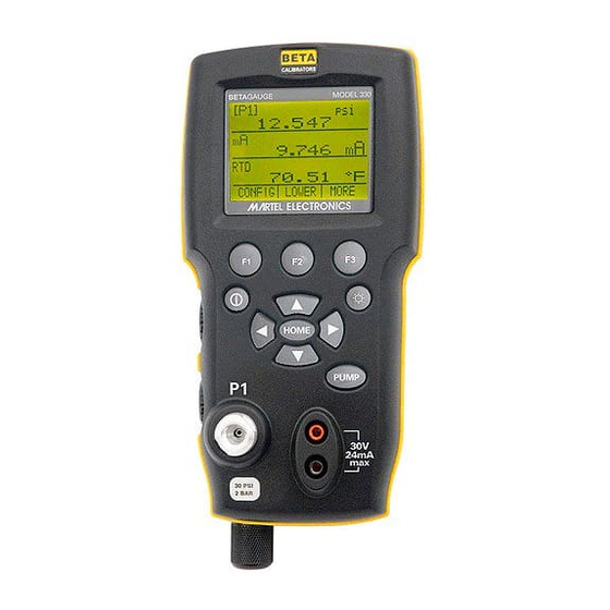
2. Calibrator Interface
Figure 1 shows the location of the pressure controls, connection port and electrical inputs.
Figure 1
4

Figures 2A and 2B show the location of the keys. Table 2 describes the function of each key.
|
Figure 2A |
|||
|
Keypad (Electric Pump Versions) |
|||
|
Table 2 Key Functions |
|||
|
No. |
Name |
Description |
|
|
1 |
Function Keys |
These are soft keys used to configure the calibrator |
|
|
2 |
ON/OFF Key |
This key is used to turn the calibrator on and off |
|
|
3 |
ZERO Key |
This key is used to zero pressure measurements |
|
|
4 |
Arrow Keys |
Used to control mA source/sim. and to set pump and % |
|
|
error limits |
|||
|
5 |
Home Key |
Return to main menu screen |
|
|
6 |
Pump Key |
Push to run pump (Electric pump version) |
|
|
6 |
Backlight |
Figure 2B only — for manual pump version |
Note: When the calibrator is turned on by pressing the ON/OFF key, it will go through a short startup self-check routine. During that routine, the display shows the current firmware revision level, auto shutdown status and the range of the internal pressure sensor. The calibrator requires a maximum of 5 minutes warm-up to rated accuracy. Large changes in ambient temperature may require a longer warm-up period. See section 2.3 for instructions on zeroing the pressure sensor displays. Pressure ranges should be zeroed each time the calibrator is started.
Figure 2B
Keypad (Manual Pump Version)
5

2.1 Calibrator Display
The Calibrator Display consists of two regions: The menu bar (located along the bottom of the screen) is used to access a menu system. The main display (the rest) consists of up to three process measurement sub-regions. These sub-regions will henceforth be referred to as the UPPER, MIDDLE and LOWER displays. Figure 3 shows the location of the different display fields while table 3 describes them.
|
Figure 3 |
||||||||
|
Display |
||||||||
|
Table 3 Display Functions |
||||||||
|
No. |
Name |
Description |
||||||
|
1 |
Primary Parameters |
Indicates what is being measured. |
||||||
|
2 |
Span Indicator |
Indicates the percent of the 4 to 20 mA span. (For mA and |
||||||
|
mA Loop functions only) |
||||||||
|
3 |
Pressure Units |
Indicates one of 15 pressure units available for display. |
||||||
|
4 |
Units |
Indicates the unit of measure for the display. |
2.1.1 Top Level Menu Functionality
There are three options for this menu: MENU, {Active Display}, and LIGHT. The Top Level Menu is home for the menu display.
2.1.1.1 Using the MENU Option
The MENU option is the gateway to the rest of the menu system. 2.1.1.2 Using the Active Display Option
The active display is indicated by the center option on the Top Level Menu. It is used to select the display to which the ZERO key will apply.
2.1.1.3 Using the LIGHT OPTION
The backlight can be toggled on and off using this key.
2.1.2 Main Menu Functionality
There are three options on the Menu, CONFIG, {Active Display} and MORE. The Main Menu is home for the menu display.
6

2.1.2.1 Setting the Active Display
The active display is indicated by the center option on the Main Menu, pressing the F2 key will toggle the active display.
2.1.2.2 Setting Active Display Parameters
To set the parameters of the active display use the CONFIG option to get to the Display Configuration Menu.
Here the SELECT option will toggle through the choices for each parameter. The first parameter is MODE. Since voltage, current and switch test modes all use the same jacks, two of these functions cannot be used concurrently. The ability to select certain functions is limited based on what is already selected in another display. The NEXT option is used to change to the second parameter. Only RTD and Pressure modes have a second parameter, RTDs can be read in Celsius or Fahrenheit and Pressures can be read in 11 engineering units.
With a single display the following modes are available:
P[1] = Pressure internal sensor.
[EXT] = Pressure with external pressure module. P[1] ST = Switch Test with left side sensor.
[EXT] ST = Switch Test with external pressure module.
Note: mA functions are only available on the Lower Display. mA measure = Milliamps measure without loop power.
mA w/24V = Milliamps measure with loop power. mA source = Milliamps source.
mA sim = Milliamps simulate using an external supply from the UUT. VOLTS = Voltage Measure.
RTD = RTD Temperature Measurement (if a probe is connected).
The following table shows which functions are available concurrently.
An X in a column indicates that the mode in the active display will not be available for selection if the mode in that row is in use in any other display.
7

Table 4 Mode Concurrency
CURRENT DISPLAY
|
DISPLAYS |
P[1] |
[EXT] |
P[1] |
[EXT] |
mA |
mA |
Volts |
RTD |
|||
|
ST |
ST |
Loop |
|||||||||
|
P[1] |
|||||||||||
|
[EXT] |
|||||||||||
|
P[1]ST |
X |
X |
X |
X |
X |
||||||
|
OTHER |
[EXT]ST |
X |
X |
X |
X |
X |
|||||
|
mA |
X |
X |
X |
X |
|||||||
|
mA Loop |
X |
X |
X |
X |
|||||||
|
Volts |
X |
X |
X |
X |
|||||||
|
RTD |
|||||||||||
|
X = Not a valid mode |
2.1.1.3 Accessing Other Menus
Use the MORE option on the Main Menu to access the other menu functions.
2.2 Using the Backlight
The backlight is controlled by the LIGHT softkey on the main menu on the models with electric pump. The 330-300 psi has a dedicated backlight key. It toggles on and off when the key is pressed; this is one of the few functions that cannot be controlled by the serial interface. There are no user configuration settings for the backlight.
2.3 Using the Zero Function
When the ZERO KEY is pressed, the calibrator will zero the active display if a pressure mode is selected, and the pressure is within the zero limit. The zero limits are within 10% of the full scale range of the selected sensor. If the display indicates “OL,” the zero function will not operate.” Note: The ZERO KEY is only used for pressure.
2.3.1 Internal Sensor and Pressure Module (non-absolute)
When a sensor or module is selected on the active display and the ZERO KEY is pressed the calibrator subtracts the current reading from the output. The zero limits are within 10% of the full scale range of the selected sensor. If the display indicates “OL,” the zero function will not operate.
2.3.2 Absolute Pressure
When an absolute pressure range is selected on the active display and the ZERO KEY is pressed the calibrator prompts the user to enter the barometric reference pressure. This is done using the arrow keys (F2 and F3 Keys). The sensor port should be open (vented) to atmosphere while performing this procedure.
8
![]()
2.4 Other Menu Controlled Functions
There are 12 ‘sub-main’ menus that can be accessed through the MORE option of the Main Menu. A ‘sub-main’ menu contains three options. The first option is unique to the function. The second and third options of a ‘sub-main’ menu are always the same. The NEXT option leads to the next ‘sub-main’ menu and the DONE option returns home . For the last ‘sub-main’ menu the NEXT option wraps around to home. See Figure 4 for a detailed mapping of the menu structure.
A note on naming convention:
If a ‘sub-main’ menu has subordinate menus, it will henceforth be referred to as {function} Main Menu. E.g. the display contrast sub-main menu will be called the
Contrast Main Menu. If not it will be called the {function} menu.
2.4.1 Setting the Contrast
From the Contrast Main Menu choose the CONTRAST option to access the Contrast Adjustment Menu.
Use the F2, F3 keys to adjust the display contrast to the desired level and then use the CONTRAST DONE option to return home.
2.4.2 Locking and Unlocking Configurations
Use the LOCK CFG or UNLOCK CFG option of the Configuration Lock Menu to lock or unlock the display configuration.
When the LOCK CFG option is chosen the menu display returns home and the CONFIG option on the Main Menu indicates that it is locked. Also all menus are locked out with the exception of the Min Max Menu, Contrast Adjustment menus and the Configuration Lock Menu. When the UNLOCK CFG option is chosen the configuration is unlocked and the menu display continues to the next sub-main menu.
2.4.3 Saving and Recalling Setups
The calibrator will automatically save the current set-up for recall at power-up. Additionally 5 set-ups can be accessed through the SETUPS menu. Select the SETUPS option from the Setups Main Menu.
Choose SAVE to save a set-up , RECALL to recall the set-up, or DONE to do nothing and return home.
9


If SAVE or RECALL is selected use the arrow keys to select the set-up location. Then use the save option to store the current set-up into the selected location or the recall option to recall the set-up stored in the selected location. The display menu will automatically go home.
2.4.4 Setting AutoShut-off Parameters
The calibrator can be set to automatically shut-off after a selected number of minutes; this function can also be disabled. To set the auto shut off parameters select the AUTO OFF option on the Auto Shut Off Main Menu.
Use the F2, F3 keys to select the number of minutes before the calibrator turns off or disable auto shut-off by scrolling all the way down.
Use the AUTO OFF DONE option to set the parameters and return home. The auto shut off time is reset whenever a key is pressed.
2.4.5 Activating and Deactivating a Display
Use the DISPLAY option on the Display Selection Main Menu to access the Display Activation Menu.
The {display} option can be used to select which display to act upon. The ON/OFF option turns the selected display on or off. The selected display and current on/off state are displayed in the lower display.
Use the DONE option to save the changes and return home. When a display is deactivated its configuration is retained. When the display is activated its configuration is
11

checked against the configurations of the other currently active displays, if the configurations are in conflict the recalled display’s configuration is modified to avoid the conflict. If all three displays are deactivated the LOWER display will come on automatically
2.4.6 Setting the RTD probe type
Use the PROBE TYPE option of the RTD Probe Type main menu to access the RTD Probe selection menu.
There are four probe types to select from P100-385, P100-392, P100-JIS and CUSTOM. Use the SELECT option to select the desired probe type and the DONE option to store the change and return home.
Note: The default probe type is PT100-385.
2.4.7 Damping
Damping can be turned ON or OFF using the Damping menu selection. When damping is ON, the calibrator displays an running average reading of ten measurements. The calibrator makes approximately 3 readings per second.
2.4.8 Pump Limits
To prevent overpressure of sensitive devices the maximum pressure (pump limit) can be set. When in this mode use the arrow keys to set the maximum pressure.
2.4.9 HART™ Resistor
An internal 250 ohm HART Resistor can be enabled when the BetaGauge 330 is operated in the “mA Measure-24V” mode. This allows a HART Communicator to be connected across the mA terminals and eliminates the need for adding an external resistor.
Note: When the HART resistor is on the maximum load driving capacity is 750 ohms.
3.Initial Setup and Basic Pressure Generation
1.The BetaGauge 330 is supplied with a special low volume calibration hose kit to facilitate faster pumping to pressure and quick pressure stabilization. the kit also comes with the required “quick-fit” hose connectors and a BSP adapter for non-NPT applications. It is highly recommended that this type of hose is used to achieve the best performance of the product. Once the fittings are installed and the calibrator is connected to the unit under test (UUT) the calibrator is ready for use. Figure 5 shows a typical setup.
12

2.Before generating pressure make sure you have the 330 configured for your application. If needed review section 2 of the manual again to select the proper configuration.
3.Make sure that the pressure vacuum knob is set for the function you want to perform (+ for pressure and – for vacuum).
4.Close the vent knob.
5.Press the pump key (or manually stroke the pump on the 300psi/20 bar model) and watch the pressure (or vacuum) increase until you reach the desired pressure.
Note: On the electric pump version the motor speed will start slowly when pressure is low (<15psi) to allow better control at low pressures.
6.Use the fine adjustment vernier to fine tune the pressure/vacuum reading as needed.
7.To reduce or bleed off the pressure entirely slowly rotate the vent knob to the open position. Doing this step carefully will allow you to control the pressure bleed rate to a high degree and will facilitate taking down-scale pressure readings.
3.1Electric Pump Considerations
The BetaGauge 330-30 and 330-150 incorporate a small, lightweight, battery powered pneumatic pump that allows the user, in the case of the 330-150 to build relatively high pressure up to 150psi (10Bar) quickly and with good control. Because the pump has an upper pressure generation limit of 160psi there may be atmospheric conditions where it cannot achieve the full scale pressure of 150psi. High altitude use (about 3000 ft or 1000 meters) or use at cold temperatures may limit the pump to about 135psi (9 Bar). In these cases the vernier adjustment can be used to generate the additional pressure needed if full scale pressure must be generated.
In these situations the user should begin the calibration with the vernier in the full counter clockwise position and then when the electric pump reaches its limit turn the vernier in the clockwise direction to raise the pressure and to set the desired reading.
 Loading…
Table of Contents for Martel BETAGAUGE 330:
-
4. Measuring Pressure To measure pressure, connect the calibrator using an appropriate fitting. Choose a pressure setting for the display being used. The calibrator is equipped with one internal sensors and many optional external sensors (EPMs) are available. Be sure to choose the sensor based on working pressures and accuracy. Note: Pressure sensors may be damaged and/or personnel injury may occur due to improper application of pressure. Please refer to the table of ranges and resolutions at the back of this manual for information on overpressure and burs
-
2.4 Other Menu Controlled Functions There are 12 ‘sub-main’ menus that can be accessed through the MORE option of the Main Menu. A ‘sub-main’ menu contains three options. The first option is unique to the function. The second and third options of a ‘sub-main’ menu are always the same. The NEXT option leads to the next ‘sub-main’ menu and the DONE option returns home . For the last ‘sub-main’ menu the NEXT option wraps around to home. See Figure 4 for a detailed mapping of the menu structure. A note on na
-
13 2. Before generating pressure make sure you have the 330 configured for your application. If needed review section 2 of the manual again to select the proper configuration. 3. Make sure that the pressure vacuum knob is set for the function you want to perform (+ for pressure and – for vacuum). 4. Close the vent knob. 5. Press the pump key (or manually stroke the p
-
2. Calibrator Interface Figure 1 shows the location of the pressure controls, connection port and electrical inputs. Figure 1 4
-
TEMP_UNIT? Returns the temperature unit, (CEL or FAR) used when measuring RTDs for each of the 3 displays. VAL? Returns the value of any measurement taking place on the upper and lower display. For example, if the upper display is measuring 5mA, and the lower display is measuring 10V, then VAL? will return: 5.000000E-03, A, 1.000000E+01, V ZERO_MEAS Zeroes the attached pressure module. Enter the zeroing value in PSI after the command when zeroing an absolute pressure module. ZERO_MEAS? Returns the zero offset or the reference value for absolute pressure modules
-
19 3. Make sure the vent on the pump is open. Zero the calibrator if necessary. Close the vent after zeroing the calibrator. 4. The top of the display will read “CLOSE”. 5. Apply pressure with the pump slowly until the switch opens. Important NOTE: In the switch test mode the display update rate is increased to help capture changing pressure inputs. Even with this enhanced sample rate pressurizing the device under test should be done slowly to ensure accurate readings. 6. Once the switch is open, “
-
24 Note: The 0% and 100% point will be saved in non-volatile memory until they are changed again by the user for the internal sensors, and external pressure modules. When using an external module the 0% and 100% are set to low and full scale of the module until the user changes it, or if it was previously saved. 10. Minimum and Maximum Storage Capability The 300 Series Pressure Calibrators have a min/max feature for capturing the minimum and maximum values of any displayed parameter. The min/max function can be acc
-
2.1.2.1 Setting the Active Display The active display is indicated by the center option on the Main Menu, pressing the F2 key will toggle the active display. 2.1.2.2 Setting Active Display Parameters To set the parameters of the active display use the CONFIG option to get to the Display Configuration Menu. Here the SELECT option will toggle through the choices for each parameter. The first parameter is MODE. Since voltage, current and sw
-
11 If SAVE or RECALL is selected use the arrow keys to select the set-up location. Then use the save option to store the current set-up into the selected location or the recall option to recall the set-up stored in the selected location. The display menu will automatically go home. 2.4.4 Setting AutoShut-off Parameters The calibrator can be set to automatically shut-off after a selected number of minutes; this function can also be disabled. To set the auto shut off parameters select the AUTO OFF option on the Auto Shut Off Main Menu. Use the F2, F3 key
-
21 9.2 Calibrating a Pressure-to-Current Transmitter To calibrate a pressure-to-current transmitter (P/I), perform the following steps: 1. Connect the calibrator and the pump to the transmitter. 2. Apply pressure with the pump. 3. Measure the current output of the transmitter. 4. Ensure the reading is correct. If not, adjust the transmitter as necessary. Figure 11.
-
38 IO_STATE? Returns the input/output/simulate state of the mA function of the calibrator. For example: If the calibrator was in mA simulate mode IO_STATE? Would return SIM. LOCAL Restores the calibrator to local operation if it was in remote mode. Also clears LOCKOUT if the calibrator was in lockout mode. LOCKOUT Sending this command sets the lockout state, when the unit is in REMOTE or goes to remote it prohibits use of the keypad completely. The lockout state can only be cleared by sending the LOCA
-
CPRT_COEFC This command is used for entering a custom RTD into the calibrator. The numeric value entered after the command will be set as the first coefficient of the polynomial used by the custom RTD. For example: CPRT_COEFC –4.183000E-12 enters –4.183000E-12 as coefficient C. CPRT_COEFC? Returns the number that was entered for the third coefficient of the polynomial used in the custom RTD. Using the example above CPRT_COEFC? Would return: –4.183000E-12 CPRT_R0 Sets the 0° resistan
-
If you send DISPLAY? It will return ON, ON, ON if the all the displays are on. FAULT? Returns the error code number of an error that has occurred. The command may be entered when the previous command did not do what it was meant to do. For example, if a value for current output is entered that is bigger than the supported range (0-24mA) FAULT? Would return: 103 which is the code number for an entry over range. Refer to the Error Codes table for more information on error code numbers. ERROR _LOOP Turns loop power on or off in percent error mode. For exam
-
26 Setup 4: The lower display is set to [P1] switch test, the other displays are off. Setup 5: The upper display is set to [P1], the middle display is set to [EXT] and the lower display is set to RTD. 12. Custody Transfer / Flow Calibration The Model 330 is ideal for flow computer calibration. Every manufacturer of flow computers has a different calibration procedure, but most call for calibration of three parameters: static pressure, differential
-
15 Figure 6 5. Measuring and Generating Current (4 to 20 mA) 1. To measure current use the input terminals in the front of the calibrator. Select the mA function on the lower display. Current is measured in mA and percentage of range. The range on the calibrator is set to 0% at 4 mA and 100% at 20 mA. For example: If the current measured is displayed as 75% then the mA value is 16 mA. Note: The display will indicate “OL” when the measured current exceeds the nominal range o
-
If you send ERROR _PORT?, it will return P1 if the pressure port in percent error is [P1]. FUNC Sets the display indicated in argument one to the function indicated in argument 2. For example: To set the lower display to RTD mode send FUNC LOWER,RTD. FUNC? Returns the current mode of all displays. For example if the calibrator is set to [P2] ST on the upper display, [P1] on the middle, and RTD on the lower, FUNC? Would return: ST_P2,P1,RTD HART_ON Turns the Hart resistor on. HART_OFF Turns the Hart resistor off. HART?
Questions, Opinions and Exploitation Impressions:
You can ask a question, express your opinion or share our experience of Martel BETAGAUGE 330 device using right now.
(Ocr-Read Summary of Contents of some pages of the Martel BETAGAUGE 330 Document (Main Content), UPD: 04 May 2023)
-
7, Martel BETAGAUGE 330 Figures 2A and 2B show the location of the keys. Table 2 describes the function of each key. Figure 2A Keypad (Electric Pump Versions) Table 2 Key Functions No. Name Description 1 Function Keys These are soft keys used to configure the calibrator 2 ON/OFF Key This key is used to turn the calibrator on and off 3 ZERO Key This key is used to zero pressure measurements 4 Arrow Keys Used to control mA source/sim. …
-
20, 18 Figure 9 8. Performing a Pressure Switch Test Figure 10 To perform a switch test, follow these steps: 1. Change the setup to Setup 4 (default switch test). Setup 4: The upper display is set to [P1] ST, all other displays are off. Important NOTE: The pressure Switch Test can be performed with the following functions[P1] ST, or EXT ST. 2. Connect the calibrator to the switch using the pressure switch terminals. The polarity of the terminals does not m…
-
46, 6. Clean the o-ring assembly and the o-ring on the retention caps with IPA and inspect the o-rings closely for any damage or excessive wear. Replacements are included in the repair kit, if needed. 7. Inspect the springs for wear or loss of tension. They should be approximately 8.6 mm long in the relaxed state. If shorter, they may not provide sufficient sealing tension. Replace if needed. 8. Once all parts have been cleaned and insp…
-
5, 3 • Do not use the calibrator if it operates abnormally. Protection may be impaired. When in doubt, have the calibrator serviced. • Do not operate the calibrator around explosive gas, vapor, or dust. • When measuring pressure, make sure the process pressure line is shut off and depressurized before you connect it or disconnect it from the pressure module. • Disconnect test leads before cha…
-
13, Martel BETAGAUGE 330 11 If SAVE or RECALL is selected use the arrow keys to select the set-up location. Then use the save option to store the current set-up into the selected location or the recall option to recall the set-up stored in the selected location. The display menu will automatically go home. 2.4.4 Setting AutoShut-off Parameters The calibrator can be set to automatically shut-off after a selected number of minu…
-
27, 25 11. Factory Setups The Calibrator is loaded with five factory commonly used setups. These setups are shown below. Note: Any of these setups can be changed and saved by the user. Setup 1: The upper display is set to [P1] mode and the lower is set to mA, middle is off. Setup 2: The upper display is set to [P1] mode and the lower is set to RTD, middle is off. Setup 3: The upper display is set to [P1] mode and the middle is …
-
47, BetaGauge 330 Ranges and Resolutions Range (PSI) 30 PSI / 2.0 Bar 150 PSI / 10 Bar 300 PSI / 20 Bar Burst Pressure (PSI) 300 300 2000 Proof Pressure (PSI) 60 200 600 Engineering Unit Factor Psi 1 30.000 150.00 300.00 bar 0.06894757 2.0684 10.3421 20.684 mbar 68.94757 2068.4 10342.1 20684 kPa 6.894757 206.84 1034.21 2068.4 MPa .00689476 0.2068 1.03421 2.0684 kg/cm2 0.07030697 2.1092 10.5460 21.092 cmH2O @ 4°C 70.3089 2109.3 10546.3 21093 cmH2O @ 20°C 70.4336 2113.0 10565.0 21130 mmH2O @ …
-
37, CPRT_COEFC This command is used for entering a custom RTD into the calibrator. The numeric value entered after the command will be set as the first coefficient of the polynomial used by the custom RTD. For example: CPRT_COEFC –4.183000E-12 enters –4.183000E-12 as coefficient C. CPRT_COEFC? Returns the number that was entered for the third coefficient of the polynomial used in the custom RTD. Using the ex…
-
44, 14. Specifications (15 °C to 35 °C unless otherwise noted.) General Instrument Setup Recall 5; last used on power-up Environmental Operating Temperature -10 °C to +50 °C Storage Temperature -20 °C to +60 °C Power Requirements 12 VDC Battery Eight (8) AA alkaline, Lithium or NiMh cells Physical Dimensions 8” H x 4” W x 2.375” D Weight 2.5 lbs. (1.2 kg) EMI/RFI Conformance EN50082-1: 1992 and EN55022: 1994 Cla…
-
6, Martel BETAGAUGE 330 2. Calibrator Interface Figure 1 shows the location of the pressure controls, connection port and electrical inputs. Figure 1 4
… -
19, 6. Measuring Voltage To measure voltage use the input terminals in the front of the calibrator. Select the Volts function on one of the displays. The calibrator can measure up to 30V. Note: The display will indicate “OL” when the measured voltage exceeds the nominal range of voltage measurement (30 V). Figure 8 7. Measuring Temperature with an RTD To measure temperature using an RTD probe you must select the RTD function on one of the d…
-
33, 13.5 Remote Commands and Error Codes The following tables list all commands, and their descriptions, that are accepted by the calibrator. Table 5: Common Commands Command Description *CLS (Clear status.) Clears the error queue. *IDN? Identification query. Returns the manufacturer, model number, and firmware revision level of the Calibrator. *RST Resets the calibrator to the power up state. Table 6: Calibrator Commands Comm…
-
16, 4. Measuring Pressure To measure pressure, connect the calibrator using an appropriate fitting. Choose a pressure setting for the display being used. The calibrator is equipped with one internal sensors and many optional external sensors (EPMs) are available. Be sure to choose the sensor based on working pressures and accuracy. Note: Pressure sensors may be damaged and/or personnel injury may occur due to improper ap…
-
32, 30 13.4.4 Calibrator Status Error Queue If an error occurs due to invalid input or buffer overflow, its error code is sent to the error queue. The error code can be read from the queue with the command FAULT?. The error queue holds 15 error codes. When it is empty, FAULT? returns 0. The error queue is cleared when power is reset or when the clear command *CLS is entered. Input Buffer Calibrator stores all received data in the input buffer. The buffer holds 25…
-
35, LOWER Designates Lower display MA Milliamps of current MEASURE Measure state MEAS_LOOP Measure with loop power state MIDDLE Designates Middle display OHM Resistance in ohms PCT_ERR Percent Error PERCENT Percent PT385_100 100 Ohm 385 Platinum RTD type PT392_100 100 Ohm 392 Platinum RTD type PTJIS_100 100 Ohm JIS Platinum RTD type P1 P1 pressure measurement function RTD Temperature measure function ST_P1 S…
-
30, 5. Select ASCII setup from File/Properties/Settings and mark these choices: Echo typed characters locally Wrap lines that exceed terminal width 6. Select Ok 7. To see if the port works enter *IDN?. This command will return information on the calibrator. 13.3 Changing Between Remote and Local Operation There are three modes of operation of the calibrator, Local, Remote, and Remote with Lockout. Local mode is the default mode.…
-
3, 1. Introduction The BetaGauge 330 is designed to be a simple to use yet very versatile pressure calibrator. Its internal pressure sensor combined with an innovative electrically powered pump along with inputs for mA, voltage, switch contacts and an RTD probe allow the 330 to calibrate virtually any pressure device. The model 330-300 uses a manual pump to reach higher pressures up to 300 psi. An external pressure…