-
Page 1
Operation Manual Bently Nevada™ Asset Condition Monitoring 3300/25 Dual Accelerometer Input Monitor Part Number 80181-01 Rev. AA (08/07) -
Page 2
Transient Data Manager, Trendmaster, TrimLoc, Velomitor Contact Information The following ways of contacting Bently Nevada are provided for those times when you cannot contact your local representative: Mailing Address 1631 Bently Parkway South Minden, Nevada USA 89423 Telephone 1.775.782.3611 1.800.227.5514 1.775.215.2873 Internet www.ge-energy.com/bently… -
Page 3
Additional Information Notice: This manual does not contain all the information required to operate and maintain the product. Refer to the following manuals for other required information. 3300 System Overview (Part Number 80171-01) 3300 System Installation Instructions (Part Number 80172-01) 3300 System Troubleshooting (Part Number 80173-01) 3300/12 Power Supply (AC supply) (Part Number 89602-01) 3300/14 Power Supply (DC supply) (Part Number 101256-01) -
Page 4
3300/25 Dual Accelerometer Input Monitor Operation Manual In this document procedures are given only for channel A. Procedures for channel B are similar except for the obvious substitutions of corresponding switches, terminals, and indicators. NOTE: The information in this manual pertains to monitor main boards with part number 105513-xx and 79552-xx (all revisions) and filter boards with part numbers 148921-01 (all revisions), 105521-01 (all revisions and 79562-01 revision J and later. -
Page 5: Table Of Contents
Contents Dual Accelerometer Monitor System …………..1 Monitor Functions ………………..2 LED Functionality………………..6 OK LEDs ………………….6 Bypass LEDs ………………..7 Alert LEDs…………………. 8 Danger LEDs ………………..9 Read Channel Values ………………10 Read Setpoint Levels………………11 Monitor Removal and Disassembly …………..12 Monitor Disassembly ………………
-
Page 6
3300/25 Dual Accelerometer Input Monitor Operation Manual 19. Appendix B–Filter Board Options PWA 79562-01 and PWA 105521-01 …54 19.1 Identify Filter Board ………………54 19.2 Filter Board Jumper Locations …………..55 19.3 Integrator/Gain Stage Flow Path…………..56 19.4 General Procedure………………57 19.5 Filter Board Options ……………….58 19.6 Integrator/Gain Stage Options …………..59 19.7… -
Page 7: Dual Accelerometer Monitor System
Section 1 — Dual Accelerometer Monitor System 1. Dual Accelerometer Monitor System Do not use this figure as a wiring diagram. Refer to 3300/25 Field Wiring Packet.
-
Page 8: Monitor Functions
3300/25 Dual Accelerometer Input Monitor Operation Manual 2. Monitor Functions DUAL ACCELEROMETER INPUT — The 3300/25 Dual Accelerometer Input Monitor provides two independent channels of on-line machine monitoring using accelerometers for the transducer inputs. Accelerometers are generally used for high frequency measurements on machines such as turbines, gear boxes, compressors, and pumps.
-
Page 9
Section 2 — Monitor Functions OK RELAY — The System OK Relay is mounted on the Power Input Module. Every channel in the rack must be OK or bypassed to energize the OK Relay. ALARM — Pressing the ALERT or DANGER switches on the monitor front panel causes the corresponding Alert (first level alarm) or Danger (second level alarm) setpoints to be displayed on the front panel meter. -
Page 10
3300/25 Dual Accelerometer Input Monitor Operation Manual transducer not OK condition. With this option, the recorder output will clamp to either +2mA or +4mA (user selectable) when a transducer is not OK. TRIP MULTIPLY — The Trip Multiply function multiplies setpoints by 2X or 3X in response to an external contact closure through terminals on the Power Input Module. -
Page 11
Section 2 — Monitor Functions… -
Page 12: Led Functionality
3300/25 Dual Accelerometer Input Monitor Operation Manual 3. LED Functionality 3.1 OK LEDs BLINK LED DISPLAY OK RELAY CONDITION DRIVE* Channel A and B are in operating range. If a channel’s OK LED goes off, that channel is not OK, has been latched not OFF** OK, or is bypassed.
-
Page 13: Bypass Leds
Section 3 — LED Functionality 3.2 Bypass LEDs BLINK LED DISPLAY CONDITION The monitor is in the Danger Bypass mode. The system is in the Power-Up mode. User invoked Self Test is in progress. BYPASS Timed OK/Channel Defeat is active. Both channels are bypassed.
-
Page 14: Alert Leds
3300/25 Dual Accelerometer Input Monitor Operation Manual 3.3 Alert LEDs BLINK ALERT LED DISPLAY CONDITION RELAY DRIVE ALERT If a channel ALERT LED comes on, that channel has exceeded its Alert setpoint ALERT level. Read Setpoint Levels, Section describes how to read alarm setpoint levels.
-
Page 15: Danger Leds
Section 3 — LED Functionality 3.4 Danger LEDs BLINK DANGER RELAY LED DISPLAY DRIVE CONDITION Voting Voting * DANGER If a channel’s DANGER LED comes on, that channel has exceeded its DANGER Danger setpoint level. Section 5 describes how to read setpoint levels.
-
Page 16: Read Channel Values
3300/25 Dual Accelerometer Input Monitor Operation Manual 4. Read Channel Values The monitor continuously indicates measured acceleration or velocity. The front panel below is indicating an acceleration of 0.9 g for channel A and 1.55 g for channel B. Note: The meter scale units must be compatible with the full scale option configured in Section…
-
Page 17: Read Setpoint Levels
Section 5 — Read Setpoint Levels 5. Read Setpoint Levels Press the ALERT switch to read Press the DANGER switch and the Alert setpoints for both read the Danger setpoints for channel A and channel B on the both channel A and channel B on meter scale.
-
Page 18: Monitor Removal And Disassembly
3300/25 Dual Accelerometer Input Monitor Operation Manual 6. Monitor Removal and Disassembly Caution Improper rack operation may occur. Power down rack or inhibit rack alarms when installing or removing a monitor. • Loosen two monitor retaining screws on the front of the monitor. •…
-
Page 19: Monitor Disassembly
Section 7 — Monitor Disassembly 7. Monitor Disassembly 7.1 Filter and Expander Board Removal Caution Component damage may result from removing the filter or expander board while power is on. Not all Dual Accelerometer Monitors contain the Expander Board. If this board does not exist, its functionality has been incorporated into the main board and connector J3 must be jumpered as shown…
-
Page 20: Filter Board Removal
3300/25 Dual Accelerometer Input Monitor Operation Manual Caution Component damage may result from removing the filter or expander board while power is on. When performing the following instructions, refer to the drawing on the previous pages. 7.1.1 Filter Board Removal 1.
-
Page 21: Front Panel Removal
Section 7 — Monitor Disassembly 7.2 Front Panel Removal 1. Disconnect J2 by pressing the connector latches outward. Caution 2. Unscrew two sliding standoffs. Component damage may result from removing the filter or expander board while power is on.
-
Page 22: Signal Input Relay Module Removal
3300/25 Dual Accelerometer Input Monitor Operation Manual 7.3 Signal Input Relay Module Removal Caution WARNING Machine protection provided by High voltage present. Contact this monitor will be lost while the could cause shock, burns, or death. Signal Input Relay Module is Do not touch exposed wires or removed from the rack.
-
Page 23: Signal Input Relay Modules (Sirm)
Section 7 — Monitor Disassembly 7.4 Signal Input Relay Modules (SIRM) A monitor can be configured with the Signal Input Relay Modules shown below. Refer to options EE & FF in Monitor Ordering Options, Section 8.2 of this manual. DUAL QUAD INTERNAL INTERNAL…
-
Page 24: No Relay And Dual Relay Sirm
3300/25 Dual Accelerometer Input Monitor Operation Manual 7.5 No Relay and Dual Relay SIRM WARNING NOTE: For relay configuration of monitors with Internal Safety Barriers, refer to High voltage present. Contact could 3300 Internal Barriers, Installation cause shock, burns, or death. Do not touch exposed wires or terminals.
-
Page 25: Quad Relay Signal Input Module Options
Section 7 — Monitor Disassembly 7.6 Quad Relay Signal Input Module Options WARNING High voltage present. Contact could cause shock, burns, or death. Do not touch exposed wires or terminals. Remove the Signal Input Relay Module from the rack before changing option jumpers. Note: AND voting logic must be done externally by wiring the contacts in series.
-
Page 26: Internal Barrier Options Sirm
3300/25 Dual Accelerometer Input Monitor Operation Manual 7.7 Internal Barrier Options SIRM For relay configuration of monitors with internal safety barriers, refer to the 3300 Internal Barriers, Installation Manual (88837) or the 3300 System Installation Instructions (80172). The Alert Relays and Danger Relays sections of the table below do not apply to the No Relay SIRM.
-
Page 27: Monitor Options
Section 8 — Monitor Options 8. Monitor Options 8.1 Field Programmable Options First Out Alert Mode Timed OK/Channel Defeat ** Enabled * Latching * Enabled * Disabled Nonlatching Disabled Alarm Delays Danger Mode Danger Relay Voting ++ 0.1 Second Latching * OR voting for relay drive * 1 Second Nonlatching…
-
Page 28: Monitor Ordering Options
3300/25 Dual Accelerometer Input Monitor Operation Manual 8.2 Monitor Ordering Options *TRANSDUCER INPUT, CHANNEL A CHANNEL B CHANNEL UNITS FULL SCALE RANGE FULL SCALE RANGE Dual accelerometer inputs; 0 to 2 g pk 0 to 2 g pk both channels indicate in acceleration units.
-
Page 29
Section 8 — Monitor Options Monitor Ordering Options (Continued) AGENCY BARRIERS ALARM TRIP APPROVAL USED RELAY MULTIPLY 00 None 00 None None None 01 CSA/NRTL/C 01 External Dual Relays, 2X trip multiply Epoxy Sealed 02 BASEEFA 02* Internal Dual Relays, 3X trip Hermetically Sealed multiply… -
Page 30: Meter Scale Replacement
3300/25 Dual Accelerometer Input Monitor Operation Manual 9. Meter Scale Replacement The monitor meter scales can be replaced for operation with different full scale ranges. The replacement meter scales are located in the back of this manual. Set the monitor full scale range. (See the Appendix A, Main Board Options.) Cut the meter scale from the back of this manual.
-
Page 31: Alarm Setpoint Adjustment
Section 10 — Alarm Setpoint Adjustment 10. Alarm Setpoint Adjustment Setpoints cannot be adjusted if trip multiply is installed and active. Trip multiply is active when the trip multiply contacts are closed. Open the front panel by loosening the two monitor retaining screws and sliding the front panel to the right.
-
Page 32: Channel Bypass
3300/25 Dual Accelerometer Input Monitor Operation Manual 11. Channel Bypass Caution Machine protection provided by this monitor will be lost while Channel Bypass is on. You can use Channel Bypass to take a Not OK or unconnected channel off line. This will restore the OK Relay to the OK state.
-
Page 33: Danger Bypass
Section 12 — Danger Bypass 12. Danger Bypass Caution Machine protection provided by this monitor will be lost while Danger Bypass is on. Open the front panel by loosening the two monitor retaining screws and sliding the front panel to the right. Set DB (Danger Bypass) switch to the left (ON).
-
Page 34: Test Alarms
3300/25 Dual Accelerometer Input Monitor Operation Manual 13. Test Alarms Use this procedure to test the alarm setpoints that you set in the Alarm Setpoint Procedure Section. The test uses a function generator to exceed the setpoint levels so that you can verify that the appropriate LEDs come on. Use this procedure to test the alarms for both channels.
-
Page 35: Connect And Adjust The Test Instruments
Section 13 — Test Alarms 13.1 Connect and Adjust the Test Instruments Caution WARNING Tests will exceed alarm setpoint High voltage present. Contact could levels causing alarms to activate. cause shock, burns, or death. This could result in relay contacts Do not touch exposed wires or changing state.
-
Page 36
3300/25 Dual Accelerometer Input Monitor Operation Manual Adjust the input frequency of the function generator according to this equation: frequency f × where: = high-pass corner frequency. = low-pass corner frequency. then use these values to calculate the input If you use.. frequency low-pass filter only = 240 CPM (4 Hz) *… -
Page 37: Test The Alert Setpoint Level
Section 13 — Test Alarms 13.2 Test the Alert Setpoint Level 1. Adjust the function generator DC offset to -7.5 Vdc. 2. Wait 30 seconds for the completion of the Timed OK/Channel Defeat delay, then press the RESET switch on the System Monitor.
-
Page 38: Test The Danger Setpoint Level
3300/25 Dual Accelerometer Input Monitor Operation Manual 13.3 Test the Danger Setpoint Level 1. Adjust the function generator amplitude past the Danger setpoint level and verify that the DANGER LED comes on (flashing if the First Out option is selected). 2.
-
Page 39: Prepare To Bring The Monitor On Line
Section 13 — Test Alarms 13.4 Prepare to Bring the Monitor On Line 1. Reduce the function generator amplitude to below the alarm setpoints and observe that the ALERT and DANGER LEDs go off (if nonlatching alarm jumpers are installed). 2.
-
Page 40: Test Ok Limits
3300/25 Dual Accelerometer Input Monitor Operation Manual 14. Test OK Limits Caution WARNING Tests will exceed alarm setpoint High voltage present. Contact could levels causing alarms to activate. cause shock, burns, or death. This could result in relay contacts Do not touch exposed wires or changing state.
-
Page 41
Section 14 — Test OK Limits 3. Adjust the power supply voltage for -7.5 Vdc with respect to common. 4. Wait 30 seconds for the completion of the Timed OK/Channel Defeat delay, then press the RESET switch on the System Monitor. Verify that the channel A OK LED is 5. -
Page 42
3300/25 Dual Accelerometer Input Monitor Operation Manual Gradually increase the power supply voltage (more negative) until the OK LED goes off (upper limit). Verify that the upper OK Limit is between -11.5 Vdc and -12.0 Vdc and that the OK Relay de-energizes. Return the power supply voltage to -7.5 Vdc and verify that the OK LED comes back on and the OK Relay energizes. -
Page 43: Calibrate Channels
Section 15 — Calibrate Channels 15. Calibrate Channels Before you begin Channel Calibration, you must choose the full scale range and set the appropriate jumpers (See Section 18.6). Calibrate both channels of your monitor. To calibrate channels you will need these instruments and tools •…
-
Page 44: Set The Filter Option To No Filters
3300/25 Dual Accelerometer Input Monitor Operation Manual 15.1 Set the Filter Option to No Filters NOTE: This procedure may alter your filter configuration. Caution WARNING Tests will exceed alarm setpoint High voltage present. Contact could levels causing alarms to activate. cause shock, burns, or death.
-
Page 45: Connect And Adjust The Test Instruments
Section 15 — Calibrate Channels 15.2 Connect and Adjust the Test Instruments (Repeat for channels A and B.) Connect the function generator to the channel A terminals as shown in the figure above. (Note: For a single transducer input system, do not repeat this step for channel B.) Adjust the function generator sine wave to 307.5 ±…
-
Page 46: Calibrate The Channels
3300/25 Dual Accelerometer Input Monitor Operation Manual 15.3 Calibrate the Channels (Repeat for channels A and B) Measure the proportional signal output at TP39 (BPPLA) for Channel A and TP40 (BPPLB) for Channel B. The testpoint locations are shown in the figure below. The voltages at these testpoints should match the voltages listed in the following table.
-
Page 47: Prepare To Bring The Monitor On Line
Section 15 — Calibrate Channels 15.4 Prepare to Bring the Monitor On Line (Repeat for channels A and B) Disconnect the test equipment and reconnect the transducer wiring A to the channel A terminals. ( Field wiring is shown the 3300/25 Field Wiring Diagram Packet.) WARNING…
-
Page 48: Self Test
3300/25 Dual Accelerometer Input Monitor Operation Manual 16. Self Test The monitor has three levels of self tests: SELF TEST PERFORMED Power-up When the monitor is turned on. Continuous during monitoring Cyclic operations. When you initiate the self test by User-invoked temporarily shorting the self-test pins.
-
Page 49
Section 16 — Self Test Recall stored error codes by using the User-invoked self test. Use the following steps to run the User-invoked self test, read error codes, and clear stored error codes: Caution Machine protection provided by this monitor will be lost for the duration of the self test. -
Page 50
3300/25 Dual Accelerometer Input Monitor Operation Manual Read any other stored error codes by pressing and holding the ALERT switch for approximately one second. For example, the display to the far right contains a second stored error code — number 10. When you reach the end of the error code list, the LCD bargraph comes on at full scale range and… -
Page 51
Section 16 — Self Test When you press the RESET switch on the System Monitor, the OK LEDs will stop flashing. -
Page 52: Error Codes
3300/25 Dual Accelerometer Input Monitor Operation Manual 17. Error Codes Refer to the Monitor Functions, Section 2 and Self Test, Section 16 for more information about displaying error codes. Refer to the Self Test section for information about clearing stored errors. ERROR DESCRIPTION EXPLANATION/RECOVERY…
-
Page 53: Appendix A-Main Board Options
Section 18 — Appendix A–Main Board Options 18. Appendix A–Main Board Options 18.1 Jumper Locations for PWA 105513-xx NOTE: This drawing applies to main boards with part number 105513-xx.
-
Page 54: Shipped As Options
3300/25 Dual Accelerometer Input Monitor Operation Manual 18.2 Shipped As Options The monitor is shipped with the following configuration: OPTION SHIPPED SETTING First Out Enabled OK Mode Nonlatching Timed OK/Channel Defeat Enabled Alert Mode Latching Recorder Outputs +4 to +20 mA +4 to +20mA Recorder Disabled Not OK Output (+2 mA clamp) *…
-
Page 55: Main Board Option Settings
Section 18 — Appendix A–Main Board Options 18.3 Main Board Option Settings Use these and the tables on the following pages to configure main board options: OPTION SETTING INSTALL REMOVE Enabled* W16C None First Out Disabled None W16C Latching W20, W23** None OK Mode Nonlatching*…
-
Page 56: Recorder Options
3300/25 Dual Accelerometer Input Monitor Operation Manual 18.4 Recorder Options Use the following table to configure Main Board 105513-xx. OPTION SETTING INSTALL REMOVE W8A,B +4 to +20 mA * W11C W11A,B W12A W12B W8A,C RECORDER OUTPUTS +1 to +5 V W11B W11A,C W12B…
-
Page 57: Channel Types
Section 18 — Appendix A–Main Board Options 18.5 Channel Types TRANSDUCER INPUT, JUMPERS CHANNEL UNITS INSTALL REMOVE Dual Accelerometer, W3B,E Channel A Acceleration W6B,E Channel B Acceleration W22B W22A ** Dual Accelerometer, W3B,F Channel A Acceleration W6B,E Channel B Velocity W22B W22A ** Dual Accelerometer,…
-
Page 58: Full Scale Options
3300/25 Dual Accelerometer Input Monitor Operation Manual 18.6 Full Scale Options Caution If you change full scale options, recalibrate both channels and replace the meter scale on the front panel. MONITOR CHANNEL A JUMPERS CHANNEL B JUMPERS FULL SCALE OPTIONS INSTALL REMOVE INSTALL…
-
Page 59: Main Board Buffered Out And Filter Options
Section 18 — Appendix A–Main Board Options 18.7 Main Board Buffered Out and Filter Options BUFFERED TRANSDUCER OUTPUT CHANNEL A CHANNEL B INSTALL REMOVE INSTALL REMOVE * Buffered transducer output not filtered. W18C W18A Buffered transducer output filtered W18A W18C * Standard configuration.
-
Page 60: Appendix B-Filter Board Options Pwa 79562-01 And Pwa 105521-01
3300/25 Dual Accelerometer Input Monitor Operation Manual 19. Appendix B–Filter Board Options PWA 79562-01 and PWA 105521-01 19.1 Identify Filter Board The configuration of the low pass filter is depends upon which filter board is being used. The filter board can be identified by looking at the PWA (Printed Wiring Assembly) number that is silkscreened on the component side of the board.
-
Page 61: Filter Board Jumper Locations
Section 19 — Appendix B–Filter Board Options PWA 79562-01 and PWA 105521-01 19.2 Filter Board Jumper Locations…
-
Page 62: Integrator/Gain Stage Flow Path
3300/25 Dual Accelerometer Input Monitor Operation Manual 19.3 Integrator/Gain Stage Flow Path This diagram is meant to illustrate the signal path through the Integrator/Gain Stage and the filters. It should not be used to determine jumper configurations. Follow the instructions in Section 19.4 determine the necessary jumper configuration.
-
Page 63: General Procedure
Section 19 — Appendix B–Filter Board Options PWA 79562-01 and PWA 105521-01 19.4 General Procedure Follow these steps, in the order below, to program the monitor to operate with or without filters. After choosing the filter type and the location of the Integrator/Gain Stage you can check the signal flow path using figure 1 in section 19.3.
-
Page 64: Filter Board Options
3300/25 Dual Accelerometer Input Monitor Operation Manual 19.5 Filter Board Options Choose the filter type by installing and removing the jumpers on the filter board as shown in the table below. See Section 19.2 for the location of the jumpers on the Filter Board.
-
Page 65: Integrator/Gain Stage Options
Section 19 — Appendix B–Filter Board Options PWA 79562-01 and PWA 105521-01 19.6 Integrator/Gain Stage Options When measuring acceleration, configure the filter after the Integrator/Gain Stage. When measuring velocity, configure: the Low-Pass filter after the Integrator/Gain Stage and the High-Pass filter before the Integrator/Gain Stage Set the location of the Integrator/Gain Stage by installing or removing the jumpers on the main and filter boards as shown in the table below.
-
Page 66
3300/25 Dual Accelerometer Input Monitor Operation Manual Channel B Integrator/Gain Stage Location CHANNEL B Main Board Filter Board INTEGRATOR/GAIN STAGE LOCATION INSTALL REMOVE INSTALL REMOVE W41,60 *Integrator/Gain Stage with W61,85 W5B,3B W3A,3C NO Filtering W3A,3C W61,85 **Filter after the W41,60 Integrator/Gain Stage W3A,3C W41,60… -
Page 67: High Pass Filter Options
Section 19 — Appendix B–Filter Board Options PWA 79562-01 and PWA 105521-01 19.7 High Pass Filter Options Install the jumpers on the filter board as shown in this table. Select frequencies not listed in this table by using the procedure in Section 19.8.
-
Page 68
3300/25 Dual Accelerometer Input Monitor Operation Manual CHANNEL A — CHANNEL B — 10020 10560 10980 11520 12060 12480 13020 13560 14040 14520 15060 16080 16500 17040 17520 18000 18540 29760 45300 1003 60180 2006 120360 2996 179760 R = REMOVE JUMPER, I = INSTALL JUMPER Use the procedure in the following section to set a high-pass corner frequency not listed in the table. -
Page 69: Non Standard High Pass Filter Options
Section 19 — Appendix B–Filter Board Options PWA 79562-01 and PWA 105521-01 19.8 Non Standard High Pass Filter Options Follow this procedure only if the desired high-pass corner frequency is not listed in the table in the previous section. Select a high-pass corner frequency, , in the range 3.7 Hz to 3008 Hz.
-
Page 70: Example High-Pass Filter Configuration
3300/25 Dual Accelerometer Input Monitor Operation Manual 19.9 Example High-Pass Filter Configuration This example shows how to configure channel A with a high-pass filter that has a corner frequency, , of 24000 CPM (400 Hz). The High Pass Filter is located after the Integrator/Gain Stage.
-
Page 71
Section 19 — Appendix B–Filter Board Options PWA 79562-01 and PWA 105521-01 Use the formula in step 3 of Section 19.8 to obtain a value for the multiplier, D. In this case: The result is D = 33.9 Step 4 of Section 19.8 requires that you convert D to the closest 8 bit binary integer. -
Page 72: Low-Pass Freq. Configuration Table
3300/25 Dual Accelerometer Input Monitor Operation Manual 19.10 Low-Pass Freq. Configuration Table Use the tables on the next four pages to select the low-pass corner frequency . The — 3dB frequency is 1.06 x . For frequencies not listed in this table, follow the procedure in the following section.
-
Page 73
Section 19 — Appendix B–Filter Board Options PWA 79562-01 and PWA 105521-01 CHANNEL A — CHANNEL B — 1440 1980 2520 2940 3540 3960 4440 5040 5520 5880 6480 6960 7500 7980 8520 9120 9600 10080 11040 12120 12960 14160 15000 15960 17040… -
Page 74
3300/25 Dual Accelerometer Input Monitor Operation Manual CHANNEL A — CHANNEL B — 25020 27780 30000 32580 35280 37500 40560 45480 49980 55560 1000 60000 1087 65220 1163 69780 1250 75000 1351 81060 1515 90900 1667 100020 2083 124980 2500 150000 3333 199980… -
Page 75
Section 19 — Appendix B–Filter Board Options PWA 79562-01 and PWA 105521-01 CHANNEL A — CHANNEL B — 25020 27780 30000 32580 35280 37500 40560 45480 49980 55560 1000 60000 1087 65220 1163 69780 1250 75000 1351 81060 1515 90900 1667 100020 2083… -
Page 76: Non Standard Low Pass Filter Options
3300/25 Dual Accelerometer Input Monitor Operation Manual 19.11 Non Standard Low Pass Filter Options Use this procedure only if the desired low pass corner frequency is not listed in the table in the previous section. The procedure consists of these two parts: •…
-
Page 77
Section 19 — Appendix B–Filter Board Options PWA 79562-01 and PWA 105521-01 5. Convert M to the closest 8 bit binary integer M0 to M7. 6. Set the anti-aliasing filter corner frequency, Install/Remove jumpers for the multiplier value M and constant K, according to the following table. -
Page 78: Setting The Low-Pass Corner Frequency
3300/25 Dual Accelerometer Input Monitor Operation Manual 19.11.2 Setting the Low-Pass Corner Frequency Select a value for clock frequency (fCLK) from this list. We recommend that you start with 3.58 MHZ. Calculate the divider ratio D using this equation. is The clock frequency, f , (in Hz) is selected in step 1 and f is the desired low pass corner frequency (in Hz).
-
Page 79
Section 19 — Appendix B–Filter Board Options PWA 79562-01 and PWA 105521-01 Set the jumpers for the input clock frequency ( ) according to this table. R = REMOVE JUMPER, I = INSTALL JUMPER SWITCHED CAPACITOR FILTER INPUT CLOCK JUMPER TABLE CHANNEL A — CHANNEL B -… -
Page 80: Divider Ratio Table
3300/25 Dual Accelerometer Input Monitor Operation Manual 19.12 Divider Ratio Table CHANNEL CHANNEL DIVIDER DIVIDER RATIO D RATIO D 2048 R = REMOVE JUMPER, I = INSTALL JUMPER…
-
Page 81: Example Low-Pass Filter Configuration
Section 19 — Appendix B–Filter Board Options PWA 79562-01 and PWA 105521-01 19.13 Example Low-Pass Filter Configuration This example shows how to configure channel B with a low-pass filter that has a corner frequency, , of 7500 CPM (125 Hz). (The resulting -3dB point is at 1.06 x or 7950 CPM (132.5 Hz).
-
Page 82
3300/25 Dual Accelerometer Input Monitor Operation Manual Calculate the multiplier value M. In this case: Convert M to the closest 8 bit binary integer. The closest integer to 32.57 is 33, and the 8 bit binary representation is 00100001. M7 is the most significant bit (MSB), and M0 is the least significant bit (LSB). -
Page 83
Section 19 — Appendix B–Filter Board Options PWA 79562-01 and PWA 105521-01 Calculate D with = 1 MHZ. 1000000 × There is not a match for D = 200 within ±1 in the Divider Ratio Table so select = 500 kHz. Calculate D with = 500 kHz. -
Page 84: Band-Pass Filters
3300/25 Dual Accelerometer Input Monitor Operation Manual 19.14 Band-Pass Filters A band-pass filter consists of cascaded high-pass and low-pass filters. To configure the Band-Pass filter, follow the instructions for programming the high-pass and low-pass filters. The center frequency of the bandpass filter is given by: f ×…
-
Page 85: Test Filter Option
Section 19 — Appendix B–Filter Board Options PWA 79562-01 and PWA 105521-01 19.15 Test Filter Option This procedure verifies filter settings by using a function generator to simulate a signal with an amplitude equal to full scale at the -3dB frequency. Since the filter attenuates a signal with this frequency by 3dB, the monitor output should be 65% to 75% of full scale.
-
Page 86
3300/25 Dual Accelerometer Input Monitor Operation Manual Adjust the settings on the function generator according to this table: PARAMETER SETTING wave form sine wave DC offset -7.5 Vdc filter corner frequency, frequency to test high pass filters (1.06) x (f to test low pass filters amplitude See step 5… -
Page 87
Section 19 — Appendix B–Filter Board Options PWA 79562-01 and PWA 105521-01 Step 5a continued: Step 5b continued: For Full Scale Range options 01, 02, For Full Scale Range options 05, 06, 03, 04, 11, 12, 13, 14 15, 16, 17 For example, if the Full Scale Range For example if the Full Scale Range option is 11, set the amplitude to 204… -
Page 88
3300/25 Dual Accelerometer Input Monitor Operation Manual The bargraph reading may be slightly lower if you have a Low Pass Filter with a corner frequency above 13.7 kHz. The reading will be lowest when the corner frequency is at its highest setting, 22.372 kHz. -
Page 89: Test Filter Option (Alternate Procedure)
Section 19 — Appendix B–Filter Board Options PWA 79562-01 and PWA 105521-01 19.16 Test Filter Option (Alternate Procedure) This procedure should only be used when your Full Scale Range Option is 05, 06, 15, 16, or 17 (see Section 8.2) and the full scale amplitude calculated in step 5b of the main procedure…
-
Page 90
3300/25 Dual Accelerometer Input Monitor Operation Manual Configure the main board as follows to change the Gain Stage back to an Integrator Stage: Channel A: Install Remove W6B,C Channel B: Install Remove W3D,E Choose an integrator test frequency according to the following criteria: The test frequency must be within the passband of the filter. -
Page 91
Section 19 — Appendix B–Filter Board Options PWA 79562-01 and PWA 105521-01 Verify that the front panel bargraph reads 85% to 95% of full scale range. The figure below shows a monitor bargraph reading 90% of full scale. Return to step 7 of the main procedure (Section 19.15). -
Page 92: Appendix C-Filter Board Options Pwa 148921-01
3300/25 Dual Accelerometer Input Monitor Operation Manual 20. Appendix C–Filter Board Options PWA 148921-01 20.1 Identify Filter Board The configuration of the low pass filter is depends upon which filter board is being used. The filter board can be identified by looking at the PWA (Printed Wiring Assembly) number that is silkscreened on the component side of the board.
-
Page 93: Filter Board Jumper Locations
Section 20 — Appendix C–Filter Board Options PWA 148921-01 20.2 Filter Board Jumper Locations…
-
Page 94: Integrator/Gain Stage Flow Path
3300/25 Dual Accelerometer Input Monitor Operation Manual 20.3 Integrator/Gain Stage Flow Path This diagram is meant to illustrate the signal path through the Integrator/Gain Stage and the filters. It should not be used to determine jumper configurations. Follow the instructions in Section 20.4 to determine the necessary jumper configuration.
-
Page 95: General Procedure
Section 20 — Appendix C–Filter Board Options PWA 148921-01 20.4 General Procedure Follow these steps, in the order below, to program the monitor to operate with or without filters. After choosing the filter type and the location of the Integrator/Gain Stage you can check the signal flow path using Figure 1 Section…
-
Page 96: Filter Board Options
3300/25 Dual Accelerometer Input Monitor Operation Manual 20.5 Filter Board Options Choose the filter type by installing and removing the jumpers on the filter board as shown in the table below. See Section 20.2 for the location of the jumpers on the Filter Board.
-
Page 97: Integrator/Gain Stage Options
Section 20 — Appendix C–Filter Board Options PWA 148921-01 20.6 Integrator/Gain Stage Options When measuring acceleration, configure the filter after the Integrator/Gain Stage. When measuring velocity, configure: the Low-Pass filter after the Integrator/Gain Stage and the High-Pass filter before the Integrator/Gain Stage Set the location of the Integrator/Gain Stage by installing or removing the jumpers on the main and filter boards as shown in the table below.
-
Page 98
3300/25 Dual Accelerometer Input Monitor Operation Manual Channel B Integrator/Gain Stage Location CHANNEL B Main Board Filter Board INTEGRATOR/GAIN STAGE LOCATION INSTALL REMOVE INSTALL REMOVE W41,60 *Integrator/Gain Stage with W61,85 W5B,3B W3A,3C NO Filtering W3A,3C W61,85 **Filter after the W41,60 Integrator/Gain Stage W3A,3C W41,60… -
Page 99: High Pass Filter Options
Section 20 — Appendix C–Filter Board Options PWA 148921-01 20.7 High Pass Filter Options Install the jumpers on the filter board as shown in this table. Select frequencies not listed in this table by using the procedure in Section 20.7. CHANNEL A- CHANNEL B- 12.5…
-
Page 100
3300/25 Dual Accelerometer Input Monitor Operation Manual CHANNEL A — CHANNEL B — 10020 10560 10980 11520 12060 12480 13020 13560 14040 14520 15060 16080 16500 17040 17520 18000 18540 29760 45300 1003 60180 2006 120360 2996 179760 R = REMOVE JUMPER, I = INSTALL JUMPER Use the procedure in the following section to set a high-pass corner frequency not listed in the table. -
Page 101: Non Standard High Pass Filter Options
Section 20 — Appendix C–Filter Board Options PWA 148921-01 20.8 Non Standard High Pass Filter Options Follow this procedure only if the desired high-pass corner frequency is not listed in the table in the previous section. Select a high-pass corner frequency, , in the range 3.7 Hz to 3008 Hz.
-
Page 102: Example High-Pass Filter Configuration
3300/25 Dual Accelerometer Input Monitor Operation Manual 20.9 Example High-Pass Filter Configuration This example shows how to configure channel A with a high-pass filter that has a corner frequency, , of 24000 CPM (400 Hz). The High Pass Filter is located after the Integrator/Gain Stage.
-
Page 103
Section 20 — Appendix C–Filter Board Options PWA 148921-01 Use the formula in step 3 of Section 20.8 to obtain a value for the multiplier, D. In this case: The result is D = 33.9 Step 4 of Section 20.8 requires that you convert D to the closest 8 bit binary integer. -
Page 104: Low Pass Filter Options
3300/25 Dual Accelerometer Input Monitor Operation Manual 20.10 Low Pass Filter Options Configure the low pass filters using the following tables. The jumper settings at the tops of the pages apply to all frequencies (rotational speeds) on their respective pages. All possible cutoff frequencies are listed.
-
Page 105
Section 20 — Appendix C–Filter Board Options PWA 148921-01 Page is blank… -
Page 106
3300/25 Dual Accelerometer Input Monitor Operation Manual Low Pass Filter Options W100 W101 W102 W103 Ch. A W200 W201 W202 W203 Ch. B Ch. A Ch. B 1380 1860 2340 2820 3300 3780 4260 4680 5160 5640 6120 6600 7020 7560 7980 8460… -
Page 107
Section 20 — Appendix C–Filter Board Options PWA 148921-01 Low Pass Filter Options (Continued) Ch. A W104 W105 W106 W107 W108 W109 W110 W111 Ch. B W204 W205 W206 W207 W208 W209 W210 W211 W112 W113 W114 W115 W116 W117 W118 Ch. -
Page 108
3300/25 Dual Accelerometer Input Monitor Operation Manual Low Pass Filter Options (Continued) W100 W101 W102 W103 Ch. A W200 W201 W202 W203 Ch. B Ch. A Ch. B 16440 16920 17340 17820 18300 18780 19260 19740 20220 20640 21600 22080 22560 23040 23520… -
Page 109
Section 20 — Appendix C–Filter Board Options PWA 148921-01 Low Pass Filter Options (Continued) Ch. A W104 W105 W106 W107 W108 W109 W110 W111 Ch. B W204 W205 W206 W207 W208 W209 W210 W211 W112 W113 W114 W115 W116 W117 W118 Ch. -
Page 110
3300/25 Dual Accelerometer Input Monitor Operation Manual Low Pass Filter Options (Continued) W100 W101 W102 W103 Ch. A W200 W201 W202 W203 Ch. B Ch. A Ch. B 31440 31920 32400 32880 33300 33840 34260 34740 35220 35700 36180 36600 37080 37560 38040… -
Page 111
Section 20 — Appendix C–Filter Board Options PWA 148921-01 Low Pass Filter Options (Continued) Ch. A W104 W105 W106 W107 W108 W109 W110 W111 Ch. B W204 W205 W206 W207 W208 W209 W210 W211 W112 W113 W114 W115 W116 W117 W118 Ch. -
Page 112
3300/25 Dual Accelerometer Input Monitor Operation Manual Low Pass Filter Options (Continued) W100 W101 W102 W103 Ch. A W200 W201 W202 W203 Ch. B Ch. A Ch. B 45540 46020 46500 46920 47400 47880 48360 48840 49320 49800 50220 50700 51180 51660 52140… -
Page 113
Section 20 — Appendix C–Filter Board Options PWA 148921-01 Low Pass Filter Options (Continued) Ch. A W104 W105 W106 W107 W108 W109 W110 W111 Ch. B W204 W205 W206 W207 W208 W209 W210 W211 W112 W113 W114 W115 W116 W117 W118 Ch. -
Page 114
3300/25 Dual Accelerometer Input Monitor Operation Manual Low Pass Filter Options (Continued) W100 W101 W102 W103 Ch. A W200 W201 W202 W203 Ch. B Ch. A Ch. B 59160 59640 R = REMOVE JUMPER, I = INSTALL JUMPER. This table is two pages wide. -
Page 115
Section 20 — Appendix C–Filter Board Options PWA 148921-01 Low Pass Filter Options (Continued) Ch. A W104 W105 W106 W107 W108 W109 W110 W111 Ch. B W204 W205 W206 W207 W208 W209 W210 W211 W112 W113 W114 W115 W116 W117 W118 Ch. -
Page 116
3300/25 Dual Accelerometer Input Monitor Operation Manual Low Pass Filter Options (Continued) W100 W101 W102 W103 Ch. A W200 W201 W202 W203 Ch. B Ch. A Ch. B 1002 60120 1042 62520 1082 64920 1123 67380 1163 69780 1203 72180 1243 74580 1282… -
Page 117
Section 20 — Appendix C–Filter Board Options PWA 148921-01 Low Pass Filter Options (Continued) Ch. A W112 W113 W114 W115 W116 W117 W118 Ch. B W212 W213 W214 W215 W216 W217 W218 W104 W105 W106 W107 W108 W109 W110 W111 Ch. -
Page 118
3300/25 Dual Accelerometer Input Monitor Operation Manual Low Pass Filter Options (Continued) W100 W101 W102 W103 Ch. A W200 W201 W202 W203 Ch. B Ch. A Ch. B 2405 144300 2445 146700 2485 149100 2525 151500 2564 153840 2604 156240 2644 158640 2684… -
Page 119
Section 20 — Appendix C–Filter Board Options PWA 148921-01 Low Pass Filter Options (Continued) Ch. A W112 W113 W114 W115 W116 W117 W118 Ch. B W212 W213 W214 W215 W216 W217 W218 W104 W105 W106 W107 W108 W109 W110 W111 Ch. -
Page 120
3300/25 Dual Accelerometer Input Monitor Operation Manual Low Pass Filter Options (Continued) W100 W101 W102 W103 Ch. A W200 W201 W202 W203 Ch. B Ch. A Ch. B 3807 228420 3846 230760 3886 233160 3926 235560 3966 237960 4007 240420 4047 242820 4087… -
Page 121
Section 20 — Appendix C–Filter Board Options PWA 148921-01 Low Pass Filter Options (Continued) Ch. A W112 W113 W114 W115 W116 W117 W118 Ch. B W212 W213 W214 W215 W216 W217 W218 W104 W105 W106 W107 W108 W109 W110 W111 Ch. -
Page 122
3300/25 Dual Accelerometer Input Monitor Operation Manual Low Pass Filter Options (Continued) W100 W101 W102 W103 Ch. A W200 W201 W202 W203 Ch. B Ch. A Ch. B 5208 312480 5248 314880 5289 317340 5329 319740 5369 322140 5409 324540 5449 326940 5489… -
Page 123
Section 20 — Appendix C–Filter Board Options PWA 148921-01 Low Pass Filter Options (Continued) Ch. A W112 W113 W114 W115 W116 W117 W118 Ch. B W212 W213 W214 W215 W216 W217 W218 W104 W105 W106 W107 W108 W109 W110 W111 Ch. -
Page 124
3300/25 Dual Accelerometer Input Monitor Operation Manual Low Pass Filter Options (Continued) W100 W101 W102 W103 Ch. A W200 W201 W202 W203 Ch. B Ch. A Ch. B 6611 396660 6651 399060 6691 401460 6732 403920 6772 406320 6812 408720 6852 411120 6892… -
Page 125
Section 20 — Appendix C–Filter Board Options PWA 148921-01 Low Pass Filter Options (Continued) Ch. A W112 W113 W114 W115 W116 W117 W118 Ch. B W212 W213 W214 W215 W216 W217 W218 W104 W105 W106 W107 W108 W109 W110 W111 Ch. -
Page 126
3300/25 Dual Accelerometer Input Monitor Operation Manual Low Pass Filter Options (Continued) W100 W101 W102 W103 Ch. A W200 W201 W202 W203 Ch. B Ch. A Ch. B 8014 480840 8054 483240 8094 485640 8134 488040 8174 490440 8214 492840 8254 495240 8294… -
Page 127
Section 20 — Appendix C–Filter Board Options PWA 148921-01 Low Pass Filter Options (Continued) Ch. A W112 W113 W114 W115 W116 W117 W118 Ch. B W212 W213 W214 W215 W216 W217 W218 W104 W105 W106 W107 W108 W109 W110 W111 Ch. -
Page 128
3300/25 Dual Accelerometer Input Monitor Operation Manual Low Pass Filter Options (Continued) W100 W101 W102 W103 Ch. A W200 W201 W202 W203 Ch. B Ch. A Ch. B 9416 564960 9456 567360 9496 569760 9536 572160 9576 574560 9615 576900 9655 579300 9695… -
Page 129
Section 20 — Appendix C–Filter Board Options PWA 148921-01 Low Pass Filter Options (Continued) Ch. A W112 W113 W114 W115 W116 W117 W118 Ch. B W212 W213 W214 W215 W216 W217 W218 W104 W105 W106 W107 W108 W109 W110 W111 Ch. -
Page 130
3300/25 Dual Accelerometer Input Monitor Operation Manual Low Pass Filter Options (Continued) W100 W101 W102 W103 Ch. A W200 W201 W202 W203 Ch. B Ch. A Ch. B 10256 615360 10416 624960 10576 634560 10736 644160 10899 653940 11059 663540 11219 673140 11379… -
Page 131
Section 20 — Appendix C–Filter Board Options PWA 148921-01 Low Pass Filter Options (Continued) Ch. A W112 W113 W114 W115 W116 W117 W118 Ch. B W212 W213 W214 W215 W216 W217 W218 W104 W105 W106 W107 W108 W109 W110 W111 Ch. -
Page 132
3300/25 Dual Accelerometer Input Monitor Operation Manual Low Pass Filter Options (Continued) W100 W101 W102 W103 Ch. A W200 W201 W202 W203 Ch. B Ch. A Ch. B 16347 980820 16507 990420 16670 1000200 16830 1009800 16990 1019400 17150 1029000 17312 1038720 17472… -
Page 133
Section 20 — Appendix C–Filter Board Options PWA 148921-01 Low Pass Filter Options (Continued) Ch. A W112 W113 W114 W115 W116 W117 W118 Ch. B W212 W213 W214 W215 W216 W217 W218 W104 W105 W106 W107 W108 W109 W110 W111 Ch. -
Page 134: Band-Pass Filters
3300/25 Dual Accelerometer Input Monitor Operation Manual 20.11 Band-Pass Filters A band-pass filter consists of cascaded high-pass and low-pass filters. To configure the Band-Pass filter, follow the instructions for programming the high-pass and low-pass filters. The center frequency of the bandpass filter is given by: f ×…
-
Page 135: Test Filter Option
Section 20 — Appendix C–Filter Board Options PWA 148921-01 20.12 Test Filter Option This procedure verifies filter settings by using a function generator to simulate a signal with an amplitude equal to full scale at the -3dB frequency. Since the filter attenuates a signal with this frequency by 3dB, the monitor output should be 65% to 75% of full scale.
-
Page 136
3300/25 Dual Accelerometer Input Monitor Operation Manual Adjust the settings on the function generator according to this table: PARAMETER SETTING wave form sine wave DC offset -7.5 Vdc filter corner frequency, frequency to test high pass filters filter corner frequency, f to test low pass filters amplitude See step 5… -
Page 137
Section 20 — Appendix C–Filter Board Options PWA 148921-01 Step 5a continued: Step 5b continued: For Full Scale Range options 05, 06, 15, 16, 17 For Full Scale Range options 01, 02, 03, 04, 11, 12, 13, 14 For example if the Full Scale Range option is 06 and the corner frequency is 53 Hz, calculate the amplitude like this: Amplitude (mVpk) =(3.25 mVpk/Hz)X(53 Hz) -
Page 138
3300/25 Dual Accelerometer Input Monitor Operation Manual The bargraph reading may be slightly lower if you have a Low Pass Filter with a corner frequency above 13.7 kHz. The reading will be lowest when the corner frequency is at its highest setting, 22.372 kHz. -
Page 139: Test Filter Option (Alternate Procedure)
Section 20 — Appendix C–Filter Board Options PWA 148921-01 20.13 Test Filter Option (Alternate Procedure) This procedure should only be used when your Full Scale Range Option is 05, 06, 15, 16, or 17 (see Section 8.2) and the full scale amplitude calculated in step 5b of the main procedure (Section 20.12) is greater than 3.5V or too small to set up accurately on your…
-
Page 140
3300/25 Dual Accelerometer Input Monitor Operation Manual Configure the main board as follows to change the Gain Stage back to an Integrator Stage: Channel A: Install Remove W6B,C Channel B: Install Remove W3D,E Choose an integrator test frequency according to the following criteria: The test frequency must be within the passband of the filter. -
Page 141
Section 20 — Appendix C–Filter Board Options PWA 148921-01 Verify that the front panel bargraph reads 85% to 95% of full scale range. The figure below shows a monitor bargraph reading 90% of full scale. Return to step 7 of the main procedure (Section 20.12). -
Page 142: Appendix D-Integrated Signals
3300/25 Dual Accelerometer Input Monitor Operation Manual 21. Appendix D–Integrated Signals 21.1 Integrator Response The integrator circuit converts a 100 mV/g acceleration signal to a 500 mV/in/sec velocity signal. The 0 dB (unity gain) frequency of the integrator occurs at approximately 307 HZ.
-
Page 143: Integrated Buffered Output Calculation
Section 21 — Appendix D–Integrated Signals 21.2 Integrated Buffered Output Calculation This section shows how to calculate the buffered output voltage for a transducer or function generator signal that is being integrated by the monitor. The formula only applies when the unfiltered signal is at the buffered output. For an unfiltered buffered output, all filters should be located after the Integrator/Gain Stage.
-
Page 144: Sample Calculation, Buffered Output
3300/25 Dual Accelerometer Input Monitor Operation Manual 21.2.1 Sample Calculation, Buffered Output Monitor is configured as: BB or CC option 16 (50 mm/sec (peak)) Input vibration level is: 1g (peak) Input signal frequency is: 100 Hz = 6000 CPM Transducer scale factor is: 100 mV/g Step 1.
-
Page 145: Integrated Meter Reading Calculations
Section 21 — Appendix D–Integrated Signals Entering component values and simplifying we get: Vout × × × × × × Taking the magnitude, we have: Vout 009097 × 21.3 Integrated Meter Reading Calculations This section shows how to calculate the front panel meter reading for a transducer or function generator signal that is being integrated by the monitor.
-
Page 146: Conversion Factor Calculation
3300/25 Dual Accelerometer Input Monitor Operation Manual If the transducer signal is simulated by a function generator, Vsig is the peak or RMS signal level. Calculate the front panel meter reading: Vsig × Front Panel Meter ading Where: ‘Vsig’ is the input voltage to monitor. ‘K’ is the conversion factor is from the tables below.
-
Page 147: Sample Calculation, Meter Output
Section 21 — Appendix D–Integrated Signals 21.3.2 Sample Calculation, Meter Output Monitor is configured as: BB or CC option 16 (50 mm/sec (peak)) Input vibration level is: 1g (peak) Input signal frequency is: 100 Hz = 6000 CPM Transducer scale factor is: 100 mV/g Step 1.
-
Page 148: Recommended Spare Parts
3300/25 Dual Accelerometer Input Monitor Operation Manual 22. Recommended Spare Parts To order replacement parts see the Specifications and Ordering Information section at the end this manual. The complete part number must be specified, as indicated on the identification decal. The part number is explained on page If you have a monitor that has been modified, the modification number must be specified on the parts order.
-
Page 149: Index
Section 23 — Index 23. Index Accelerometer………………….2,22 Alarm……………………3,25 Alert……………………..3 AND Voting ………………….3,9,19 Buffered Output………………..3,21,53 Buffered Output, Integrated ………………137 Bypass, Channel ………………..2,26 Bypass, Danger …………….3,27,32,33,82,132 Calibration……………………. 37 Calibration with Filter / Integrator …………… 79,129 Channel Bypass………………….
-
Page 150
3300/25 Dual Accelerometer Input Monitor Operation Manual LED, Alarm ……………………3 LED, Alert …………………..3,8,31,41 LED, Bypass ………………..2,3,7,26,27 LED, Danger ………………..3,9,27,41 LED, OK…………………..2,4,6,26,41 Meter Reading ………………..10,11,140 Not OK Channel………………….6 NOT OK Mode ………………..2,34,41 OK ………………………2,6 OK Limits ……………………2 OK Mode……………………2 OK Relay ……………………2 Options, Monitor ………………
-
Contents
-
Table of Contents
-
Bookmarks
Quick Links
Operation Manual
Bently Nevada™ Asset Condition Monitoring
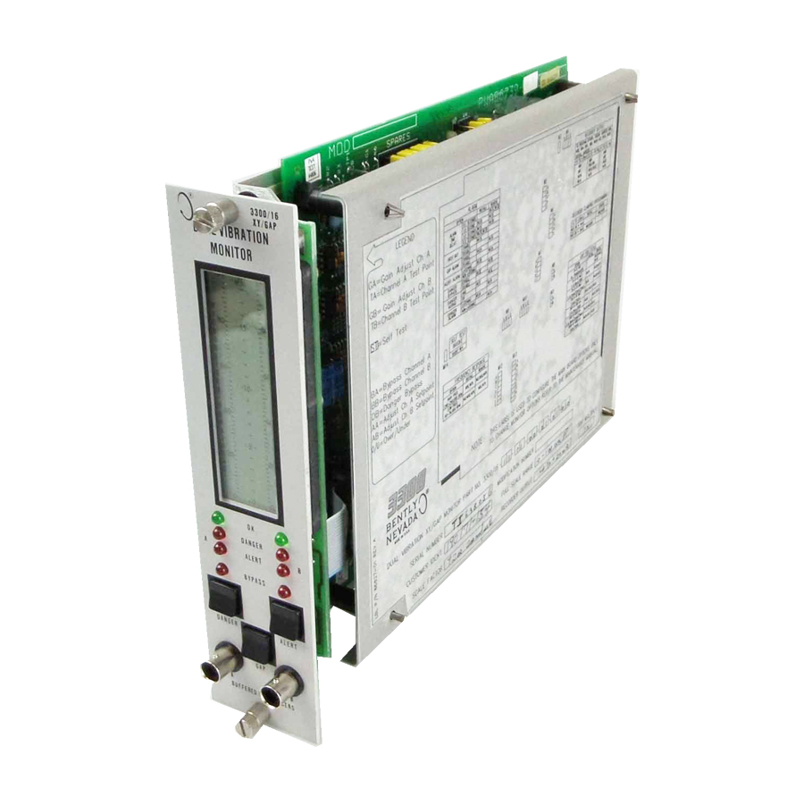
3300/16 Dual Vibration Monitor
Part Number 86830-01
Rev. P (08/07)
Related Manuals for GE Bently Nevada 3300/16
Summary of Contents for GE Bently Nevada 3300/16
-
Page 1
Operation Manual Bently Nevada™ Asset Condition Monitoring 3300/16 Dual Vibration Monitor Part Number 86830-01 Rev. P (08/07) -
Page 2
1631 Bently Parkway South Minden, Nevada USA 89423 Telephone 1.775.782.3611 1.800.227.5514 1.775.215.2873 Internet www.ge-energy.com/bently Note: In this document procedures are given only for channel A. Procedures for channel B are similar except for the obvious substitutions of corresponding switches, terminals, and indicators. -
Page 3
Additional Information Notice: This manual does not contain all the information required to operate and maintain the product. Refer to the following manuals for other required information. 3300 System Overview (Part Number 80171-01) 3300 System Installation Instructions (Part Number 80172-01) 3300 System Troubleshooting (Part Number 80173-01) 3300/12 AC Power Supply (Part Number 89602-01) 3300/14 DC Power Supply (Part Number 101256-01) -
Page 4: Table Of Contents
3300/16 Dual Vibration Monitor Operation Manual Contents 1. Dual Vibration Monitoring System …………..1 2. Front Panel Features………………2 3. Monitor Functions ………………3 4. Channel Vibration……………….6 5. LED Functionality………………..7 OK LEDs…………………………7 Bypass LEDs……………………….8 Alert LEDs………………………… 9 Danger LEDs ……………………….10 6. Read Gap Voltage ………………11 7.
-
Page 5
15.2 Test Channel Alarms ……………………27 15.3 Test Gap Alarms……………………..29 15.4 Channel B and Reinstallation…………………30 Test OK Limits ………………. 31 16.1 Test Equipment Setup ……………………31 16.2 Test Upper OK Limit……………………32 16.3 Test Lower OK Limit……………………32 16.4 Channel B and Reinstallation…………………33 Calibrate Channels ……………… 34 17.1 Calibration Equipment Setup…………………34 17.2… -
Page 6
3300/16 Dual Vibration Monitor Operation Manual 23.6 Transducer Input Options………………….59 23.7 Trip Multiply……………………….60 Recommended Spare Parts…………..61 Index ………………….63… -
Page 7: Dual Vibration Monitoring System
Section 1 — Dual Vibration Monitoring System 1. Dual Vibration Monitoring System…
-
Page 8: Front Panel Features
3300/16 Dual Vibration Monitor Operation Manual 2. Front Panel Features…
-
Page 9: Monitor Functions
Section 3 — Monitor Functions 3. Monitor Functions RADIAL VIBRATION — Radial vibration is defined as shaft dynamic motion in a direction perpendicular to the shaft centerline. The Dual Vibration Monitor displays values for two channels (Channel A and B). PROBE GAP VOLTAGE — Probe gap is measured as a negative dc voltage that is directly proportional to the gap distance between the face of a proximity probe and the surface being monitored.
-
Page 10
3300/16 Dual Vibration Monitor Operation Manual GAP ALARM — Pressing the GAP and ALERT switches simultaneously displays the Gap Alert setpoints. When the gap level is equal to or outside the over and under setpoint window limits for 6 seconds, the ALERT LEDs come on and the appropriate Alert Alarm relay contacts are activated. -
Page 11
Section 3 — Monitor Functions The recorder clamping option, available when the +4 to +20 mA recorder output is selected, allows the user to choose the recorder output level used to annunciate a transducer not OK condition. With this option, the recorder output will clamp to either +2 mA or +4 mA (user selectable) when a transducer is not OK. -
Page 12: Channel Vibration
3300/16 Dual Vibration Monitor Operation Manual 4. Channel Vibration The monitor continuously indicates measured vibration for channels A and B.
-
Page 13: Led Functionality
Section 5 — LED Functionality 5. LED Functionality 5.1 OK LEDs Note: Since each channel in the system controls the OK Relay, either channel can cause a Not OK Relay condition (deenergized relay). LED Display Condition OK Relay Drive Channel A and B in operating range. Respective channel A or B transducer in Not OK condition or bypassed.
-
Page 14: Bypass Leds
3300/16 Dual Vibration Monitor Operation Manual 5.2 Bypass LEDs LED Display Condition BYPASS Monitor in Danger Bypass mode or System in Power-Up mode or User-invoked self-test in progress or Timed OK/Channel Defeat or both Channels bypassed or Monitor has detected an active error or Rack Inhibit Contacts at back of rack closed.
-
Page 15: Alert Leds
Section 5 — LED Functionality 5.3 Alert LEDs LED Display Condition Alert Relay Drive ALERT Vibration signal has exceeded the channel A alert level (see section 7.1). ALERT Vibration signal has exceeded the channel B alert level (see section 7.1). ALERT Vibration signal has exceeded the channel A and B alert level (see section…
-
Page 16: Danger Leds
3300/16 Dual Vibration Monitor Operation Manual 5.4 Danger LEDs LED Display Danger Relay Drive Condition “or” voting “and” voting DANGER Vibration has exceeded the channel A danger level (see section 7.2). DANGER Vibration has exceeded the channel B danger level (see section 7.2).
-
Page 17: Read Gap Voltage
Section 6 — Read Gap Voltage 6. Read Gap Voltage Press the GAP switch to read the Gap values for both channel A and B using the center meter scale. For example, this monitor is indicating a Gap voltage of 6 Vdc for channel A and 3 Vdc for channel B.
-
Page 18: Read Setpoint Values
3300/16 Dual Vibration Monitor Operation Manual 7. Read Setpoint Values 7.1 Read Alert Setpoints Press the ALERT switch to read the Alert Press the GAP and ALERT switches setpoint for both channel A and B on the simultaneously to read the Gap Alert meter scale.
-
Page 19: Read Danger Setpoints
Section 7 — Read Setpoint Values 7.2 Read Danger Setpoints Press the DANGER switch to read the Danger setpoints for both channel A and B on the meter scale. This monitor shows a Danger setpoint of 7.6 mil for channel A and 6.2 mil for channel B.
-
Page 20: Monitor Removal
3300/16 Dual Vibration Monitor Operation Manual 8. Monitor Removal Caution Improper rack operation may occur. Power down rack or inhibit rack alarms when installing or removing a monitor. 1. Loosen two screws. 2. Pull monitor from rack.
-
Page 21: Monitor Disassembly
Section 9 — Monitor Disassembly 9. Monitor Disassembly 9.1 Side Cover Removal Caution Components are sensitive to Electro-Static Discharge (ESD). Proper grounding should be implemented prior to removing the Side Cover Panel. 1. Squeeze the retaining tips on each standoff. 2.
-
Page 22: Front Panel Removal
3300/16 Dual Vibration Monitor Operation Manual 9.2 Front Panel Removal…
-
Page 23: Input Module
Section 9 — Monitor Disassembly WARNING High voltage present. Contact could cause shock, burns, or death. Do not touch exposed wires or terminals 9.3 Input Module The Signal Input Relay Module is on the back of the rack. For relay configuration, see 3300 System Installation Instructions.
-
Page 24: Dual Relay Module Options
3300/16 Dual Vibration Monitor Operation Manual 9.3.2 Dual Relay Module Options Alert Relay Jumper Normally Energized W4, W11 Normally De-energized* W4, W11 Danger Relay Jumper Normally Energized W1, W12 Normally De-energized* W1, W12 OR Bus** Jumper No Options* ———- W5 — W8 Alert &…
-
Page 25: Monitor Options
Section 10 — Monitor Options 10. Monitor Options PART FULL TRANSDUCER INPUT ALARM RELAY AGENCY NUMBER SCALE APPROVAL RANGE 3300/16 – AXX – BXX – CXX — 01 = 3300 8mm or 01 = 0 — 3 mil pp 00 = NONE 00 = NOT REQUIRED 7200 5mm &…
-
Page 26
3300/16 Dual Vibration Monitor Operation Manual supply voltage of -18 Vdc, while the 3300 and 7200 transducers require -24 Vdc. Power converter (part number 89634-01) can be used to convert -24 Vdc to -18 Vdc for use with the 3000 transducer. IMPORTANT! Due to continuing changes in technology, the Main PWA (printed wiring assembly) has been upgraded to improve functionality and manufacturability. -
Page 27: Meter Scale Replacement
Section 11 — Monitor Options 11. Meter Scale Replacement To replace a meter scale 1. Set the vibration full-scale range and gap full-scale range. (See Section 10, Monitor Options) 2. Cut the selected vibration meter scale and clear adhesive backed gap scale from the back of this manual.
-
Page 28: Alarm Setpoint Adjustment
3300/16 Dual Vibration Monitor Operation Manual 12. Alarm Setpoint Adjustment 12.1 Alert and Danger Setpoint Adjustment Caution Changing Alarm Setpoints will change the trip levels of the machine. 1. Open front panel. 2. Set the adjust channel A switch (AA) to the left (ON). The left (Channel A) bargraph will start flashing the channel A vibration signal.
-
Page 29: Gap Alert Setpoint Adjustment
Section 12 — Alarm Setpoint Adjustment 12.2 Gap Alert Setpoint Adjustment 1. To adjust Gap Alert setpoints, first select Under Gap setpoints by setting the Over/Under (O/U) switch to the right. 2. Press and hold the GAP and ALERT switches simultaneously on the front panel.
-
Page 30: Channel Bypass
3300/16 Dual Vibration Monitor Operation Manual 13. Channel Bypass You can use Channel Bypass to take a NotOK or unconnected channel off line. This will restore the OK Relay to the OK state. The OK Relay will de-energize (go NotOK) if any channel in the rack is in a NotOK condition.
-
Page 31: Danger Bypass
Section 14 — Channel Bypass 14. Danger Bypass You can use Danger Bypass to bypass the DANGER Relay. The DANGER alarm LEDs on the front panel can come on but the DANGER Relay drive will not be activated if a Danger setpoint is exceeded.
-
Page 32: Test Alarms
3300/16 Dual Vibration Monitor Operation Manual 15. Test Alarms 15.1 Test Equipment Setup WARNING High voltage present. Contact could cause shock, burns or death. Do not touch exposed wires or terminals. Caution Tests will exceed alarm setpoint levels and cause alarms to activate.
-
Page 33: Test Channel Alarms
Section 15 — Test Alarms 15.2 Test Channel Alarms 1. To test vibration alarms for channel A, adjust the signal amplitude such that the vibration signal is below the Alert and Danger alarm setpoint levels on the monitor. 2. Wait for the 30-second Timed OK/Channel Defeat delay time to elapse.
-
Page 34
3300/16 Dual Vibration Monitor Operation Manual 7. Adjust the signal amplitude such that the vibration signal on the monitor just exceeds the Danger setpoint level and verify that the DANGER LED comes on after the optioned vibration alarm delay period has elapsed (flashing if First Out option is selected). -
Page 35: Test Gap Alarms
Section 15 — Test Alarms 15.3 Test Gap Alarms • If the Gap Full Scale Range option is in engineering units instead of volts, this section still applies with the exception that the gap value will be referenced to zero position at the center of the meter scale.
-
Page 36: Channel B And Reinstallation
3300/16 Dual Vibration Monitor Operation Manual 5. Reduce the gap voltage to read below the Over Gap setpoint (and above the Under Gap Setpoint) and observe that the ALERT LED goes off (if the nonlatching alarm jumper is installed). Press the RESET switch on the System Monitor to reset latching alarms. 6.
-
Page 37: Test Ok Limits
Section 16 — Test OK Limits 16. Test OK Limits 16.1 Test Equipment Setup WARNING High voltage present. Contact could cause shock, burns or death. Do not touch exposed wires or terminals. Caution Tests will exceed Gap Alert setpoint levels and cause alarms to activate (if enabled).
-
Page 38: Test Upper Ok Limit
3300/16 Dual Vibration Monitor Operation Manual 16.2 Test Upper OK Limit 1. Increase the power supply voltage (more negative) until the OK LED goes off (upper limit). • Verify that the upper OK limit is within the upper OK voltage range (reference Table 4 on the next page).
-
Page 39: Channel B And Reinstallation
Section 16 — Test OK Limits 16.4 Channel B and Reinstallation 1. When finished, disconnect the power supply and multimeter and reconnect the COM and IN wiring to the channel terminals on the Signal Input Relay Module. Verify that the OK LED comes on and the OK Relay energizes.
-
Page 40: Calibrate Channels
3300/16 Dual Vibration Monitor Operation Manual 17. Calibrate Channels 17.1 Calibration Equipment Setup WARNING Caution High voltage present. Tests will exceed alarm setpoint Contact could cause shock, burns or levels and cause alarms to death. activate. Relay contacts may change state. See Danger Do not touch exposed wires or Bypass Section 14.
-
Page 41: Calibration Procedure
Section 17 — Calibrate Channels 1. Disconnect COM and IN wiring from the channel A terminals on the Signal Input Relay Module. 2. Connect function generator and multimeter to COM and IN with polarity as shown in the Calibration Setup diagram on the previous page. •…
-
Page 42
3300/16 Dual Vibration Monitor Operation Manual 3. Measure the proportional signal output voltage at channel A test point (TA) using the multimeter as shown in the figure to the right and verify that it matches the table below. Proportional Signal Output No Trip Multiply +5.00 Vdc 2X Trip Multiply… -
Page 43: Zero Position Adjustment
Section 18 — Zero Position Adjustment 18. Zero Position Adjustment Note: Before performing this procedure, verify that the probe gap voltage is at the value you want to set as your zero value. 1. Open the front panel. 2. Set the adjust channel A switch (AA) to the left.
-
Page 44
3300/16 Dual Vibration Monitor Operation Manual NOTE: The gap zero position voltage must be within the limits shown in the table below for the applicable transducer and gap full scale range or your gap full scale range may go outside the transducer OK limits. 3300 OR 7200 5 &… -
Page 45: Self Test
Section 19 — Self Test 19. Self Test The monitor has three levels of self-test: SELF TEST PERFORMED Power — up When the monitor is turned on. Cyclic Continuous during monitoring operations. User-invoked When you initiate the self-test by temporarily shorting the self-test pins.
-
Page 46
3300/16 Dual Vibration Monitor Operation Manual Recall stored error codes by using the User-invoked self-test. Use the following steps to run the User- invoked self-test, read error codes, and clear stored error codes: Caution Machine protection will be lost during calibration and for the duration of the self-test. -
Page 47
Section 19 — Self Test Read any other stored error codes by pressing and holding the ALERT switch for approximately one second. For example, the display to the far right contains a second stored error code — number 10. • When you reach the end of the error code list, the LCD bargraph comes on at full scale range and the OK LEDs… -
Page 48
3300/16 Dual Vibration Monitor Operation Manual When you press the RESET switch on the System Monitor, the OK LEDs will stop flashing. -
Page 49: Error Codes
Section 20 — Self Test 20. Error Codes ERROR DESCRIPTION EXPLANATION/RECOVERY CODE ROM checksum failed. Tested at Power-up and User-invoked self test. This error is displayed on the front panel, but is not stored in memory. Install your spare monitor or contact your local Bently Nevada office for service.
-
Page 50: Appendix A — Monitor Options For Pwa 140720-01
3300/16 Dual Vibration Monitor Operation Manual 21. Appendix A – Monitor Options for PWA 140720-01 21.1 Jumper Locations for PWA 140720-01 IMPORTANT! W19, 22, 23, 26, and 27 are for factory use only and should not be changed. These jumpers are labeled «Factory Use Only»…
-
Page 51: Main Board Option Settings
Section 21 — Appendix A – Monitor Options for PWA 140720-01 21.2 Main Board Option Settings All monitor option jumpers for the Dual Vibration Monitor are on the Main Board. The following table lists these options and their jumper positions. Option Settings on Newer Version of the Main Board (Part Number 140720-01) JUMPER OPTION…
-
Page 52: Recorder Output Options
3300/16 Dual Vibration Monitor Operation Manual 21.3 Recorder Output Options To set the recorder output, remove all jumpers from headers W17A, B, C, D, G, H, I, J. Install jumpers as specified in the following table. Recorder Output Options, W17 Recorder Output +4 to +20 mA * +1 to +5 Vdc 0 to -10 Vdc…
-
Page 53: Vibration Full Scale Range Options
Section 21 — Appendix A – Monitor Options for PWA 140720-01 21.5 Vibration Full Scale Range Options To set the vibration full-scale range option, remove jumpers W15E-H, W24A-D, W25A-D. Install jumpers specified in the following table. Caution Changing full scale requires re- calibration of both channels (see Calibrate Channels section).
-
Page 54: Transducer Input Options
3300/16 Dual Vibration Monitor Operation Manual 21.6 Transducer Input Options To set the transducer input option, remove jumpers W15I, J, K, L, M, N, O, P / W20M, N. Install jumpers specified in following table. Transducer Input Options Transducer Input Install Jumpers 3300 8mm, 3300XL 8mm or…
-
Page 55
Section 21 — Appendix A – Monitor Options for PWA 140720-01 If you want to change the Trip Multiply configuration, use the following table to change the appropriate jumpers: Remove W15Q-T, W17K-N, W20O-P Install the following jumpers Configuration Jumpers No Trip Multiply Q, R, S, T K, L, M, N ——-… -
Page 56: Appendix B — Monitor Options For Pwa 135305-01
3300/16 Dual Vibration Monitor Operation Manual 22. Appendix B — Monitor Options for PWA 135305-01 22.1 Jumper Locations for 135305-01 This section shows the jumper configuration for PWA 135305-01 only. The Dual Vibration Monitor has several user-programmable options. The options can be changed by removing and installing jumpers on the main circuit board.
-
Page 57: Main Board Option Settings
Section 22 — Appendix B — Monitor Options 22.2 Main Board Option Settings All monitor option jumpers for the Dual Vibration Monitor are on the Main Board. The following table lists these options and their jumper positions. Option Settings on Newer Version of the Main Board (Part Number 135305-01) JUMPER OPTION SETTING…
-
Page 58: Recorder Output Options
3300/16 Dual Vibration Monitor Operation Manual 22.3 Recorder Output Options To set the recorder output, remove all jumpers from headers W17A, B, C, D, G, H, I, J. Install jumpers as specified in the following table. Recorder Output Options, W17 Recorder Output +4 to +20 mA * +1 to +5 Vdc…
-
Page 59: Vibration Full Scale Range Options
Section 22 — Appendix B — Monitor Options 22.5 Vibration Full Scale Range Options To set the vibration full-scale range option, remove jumpers W15E-H, W24A-D, W25A-D. Install jumpers specified in the following table. Caution Changing full scale requires re- calibration of both channels (see Calibrate Channels section).
-
Page 60: Transducer Input Options
3300/16 Dual Vibration Monitor Operation Manual 22.6 Transducer Input Options To set the transducer input option, remove jumpers W15I, J, K, L, M, N, O, P / W20M, N. Install jumpers specified in following table. Transducer Input Options 22.6.1.1 Transducer Input 22.6.1.2 Install Jumpers…
-
Page 61
Section 22 — Appendix B — Monitor Options Remove W15Q-T, W17K-N, W20O-P Install the following jumpers Configuration Jumpers No Trip Multiply Q, R, S, T K, L, M, N ——- 2X Trip Multiply R, T L, N 3x Trip Multiply —— ——… -
Page 62: Appendix C — Monitor Options For Pwa 86739-01
3300/16 Dual Vibration Monitor Operation Manual 23. Appendix C – Monitor Options for PWA 86739-01 23.1 Jumper locations for 86739-01. This section shows the jumper configuration for the 86739-01 PWA only. The Dual Vibration Monitor has several user-programmable options. The options can be changed by removing and installing jumpers on the main circuit board.
-
Page 63: Main Board Option Settings
Section 23 — Appendix C – Monitor Options for PWA 86739-01 23.2 Main Board Option Settings All monitor option jumpers for the Dual Vibration Monitor are on the Main Board. The following table lists these options and their jumper positions. Option Settings on Older Version of the Main Board (Part Number 86739-01) JUMPER OPTION…
-
Page 64: Recorder Output Options
3300/16 Dual Vibration Monitor Operation Manual 23.3 Recorder Output Options To set the recorder output, remove all jumpers from headers W8A, W8B, W9A, W9C, W9D, W10A-C, W11A, W11B. Install jumpers as specified in the following table. Recorder Output Options Recorder Output +4 to +20 mA * +1 to +5 Vdc 0 to -10 Vdc…
-
Page 65: Vibration Full Scale Range Options
Section 23 — Appendix C – Monitor Options for PWA 86739-01 23.5 Vibration Full Scale Range Options To set the vibration full-scale range option, remove jumpers W4A-D, W5A, W5B, W7D-E. Install jumpers specified in the following table. Vibration Full Scale Range Options Vibration Full Scale Range Install Jumpers 0 –…
-
Page 66
3300/16 Dual Vibration Monitor Operation Manual 23.7 Trip Multiply Trip multiply requires the installation of option jumpers (W13I or W13H) and removal of components. To change the trip multiply option, contact Bently Nevada Product Service. -
Page 67: Recommended Spare Parts
Section 24 — Recommended Spare Parts 24. Recommended Spare Parts QTY PER DESCRIPTION REPLACEMENT PART NUMBER MONITOR FRONT PANEL ASSEMBLY Order complete catalog number MONITOR CIRCUIT ASSEMBLY SPARE JUMPERS (100 PIECES) 88706-01 SIGNAL INPUT RELAY MODULE NO RELAY 81544-01 * EPOXY SEALED RELAY 81545-01 * HERMETICALLY SEALED RELAY…
-
Page 68
3300/16 Dual Vibration Monitor Operation Manual If the monitor has been modified, specify the modification number on the parts order. User must set programmable options (reference section 21, 22, or 23 of this manual). If in doubt about the part number, call your local sales representative before ordering. -
Page 69: Index
Section 25 — Index 25. Index Alarm…………………………….. 3 Alarm Setpoints……………………….23, 44 Alert LED …………………………9, 28, 30, 31 Alert Setpoints…………………………. 12, 23 Approvals …………………………..20 Barriers…………………………18, 20, 39 Buffered Output …………………………4 Bypass LED……………………..3, 8, 25, 26, 40, 41 Calibrate Channels ………………………..35 Channel Bypass……………………3, 4, 25, 31, 34, 37 ………………………..18 Common Relay OR Bus…
-
Page 70
3300/16 Dual Vibration Monitor Operation Manual Recorder Outputs ……………………..5, 47, 53, 59 Relays …………………………4, 18, 20, 62 Replacement Parts ………………………..62 Reset …………………. 3, 4, 7, 28, 29, 30, 31, 33, 34, 37, 43 Self Test…………………………. 5, 40, 44 Setpoint Values…………………………12 Signal Input Module ………………………

Operation Manual
Bently Nevada™ Asset Condition Monitoring
3300 System Compatibility Guide
Part Number 104003-01
Rev. G (08/07)

3300 System Compatibility Guide Operation Manual
Copyright © 1993. Bently Nevada LLC.
All rights reserved.
The information contained in this document is subject to change without notice.
The following are trademarks of General Electric Company in the United States and other countries:
Bently Nevada, Data Manager, Key , Keyphasor, System 1, TDXnet, Transient Data Manager
The following are trademarks of the legal entities cited:
Allen-Bradley® is a trademark of Rockwell Automation.
MODBUS™ is a trademark of Schneider Electric.
Contact Information
The following ways of contacting Bently Nevada are provided for those times when you cannot contact your local representative:
|
Mailing Address |
1631 Bently Parkway South |
|
Minden, Nevada USA 89423 |
|
|
USA |
|
|
Telephone |
1.775.782.3611 |
|
1.800.227.5514 |
|
|
Fax |
1.775.215.2873 |
|
Internet |
www.ge-energy.com/bently |
ii

Additional Information
Notice:
This manual does not contain all the information required to operate and maintain the product. Refer to the following manuals for other required information.
3300 System Overview (Part Number 80171-01)
3300 System Installation Instructions (Part Number 80172-01)
3300 System Troubleshooting (Part Number 80173-01) 3300/12 AC Power Supply (Part Number 89602-01) 3300/14 DC Power Supply,(Part Number 101256-01) 3300/02 TDe System Monitor (Part Number 167388-01) 3300/03 SDI/DDI System Monitor (Part Number 89604-01) 3300 Internal Barrier Manual (Part Number 88837-01)
Product Disposal Statement
Customers and third parties, who are not member states of the European Union, who are in control of the product at the end of its life or at the end of its use, are solely responsible for the proper disposal of the product. No person, firm, corporation, association or agency that is in control of product shall dispose of it in a manner that is in violation of any applicable federal, state, local or international law. Bently Nevada LLC is not responsible for the disposal of the product at the end of its life or at the end of its use.
SYMBOLS
Special symbols are used in the manual to illustrate specifics in the step-by-step processes. For example:
|
Press |
Flashing |
Connect |
Disconnect |
Observe |
Screwdriver |
iii

3300 System Compatibility Guide Operation Manual
|
Contents |
|||
|
1. |
Purpose ………………………………………………………………………………………………………………………………………………………….. |
1 |
|
|
2. |
System Identification ………………………………………………………………………………………………………………………………….. |
4 |
|
|
2.1 |
Configuration Definitions………………………………………………………………………………………………………………… |
4 |
|
|
2.1.1 |
Original System…………………………………………………………………………………………………………………………….. |
4 |
|
|
2.1.2 |
Mixed System………………………………………………………………………………………………………………………………… |
4 |
|
|
2.1.3 |
SDI/DDI System…………………………………………………………………………………………………………………………….. |
4 |
|
|
2.1.4 |
TDe System ……………………………………………………………………………………………………………………………………. |
5 |
|
|
2.2 |
System Identification……………………………………………………………………………………………………………………….. |
6 |
|
|
2.2.1 |
Original System…………………………………………………………………………………………………………………………….. |
7 |
|
|
2.2.2 |
Mixed System………………………………………………………………………………………………………………………………… |
8 |
|
|
2.2.3 SDI/DDI or TDe System……………………………………………………………………………………………………………….. |
9 |
||
|
2.3 |
Rack Identification …………………………………………………………………………………………………………………………. |
10 |
|
|
2.3.1 |
Original Backplane ……………………………………………………………………………………………………………………. |
11 |
|
|
2.3.2 SDI/DDI or TDe Backplane………………………………………………………………………………………………………. |
12 |
||
|
2.4 |
Monitor Firmware Identification…………………………………………………………………………………………………. |
13 |
|
|
3. |
System Compatibility……………………………………………………………………………………………………………………………….. |
16 |
|
|
3.1 |
Mixed System Compatibility Issues……………………………………………………………………………………………. |
16 |
|
|
3.2 |
Additional Compatibility Issues…………………………………………………………………………………………………… |
16 |
|
|
3.2.1 |
Monitors……………………………………………………………………………………………………………………………………….. |
16 |
|
|
3.2.2 |
Communications Processors …………………………………………………………………………………………………. |
16 |
|
|
3.3 |
Communication Processor and Software Compatibility ……………………………………………………… |
17 |
|
|
4. |
Appendix A………………………………………………………………………………………………………………………………………………….. |
18 |
|
|
4.1 |
Hardware Upgrade Kit Part Numbers………………………………………………………………………………………. |
18 |
|
|
5. |
Appendix B………………………………………………………………………………………………………………………………………………….. |
19 |
|
|
5.1 |
Firmware Upgrade Kit Part Numbers……………………………………………………………………………………….. |
19 |
iv

Section 1 — Purpose
1. Purpose
Since the original design of the 3300 monitoring system, the Serial Data Interface/Dynamic Data Interface (SDI/DDI) communication protocols have been added. As a result, there are now three different 3300 configurations in the field: Original, Mixed, and SDI/DDI configurations. The purpose of this Compatibility Guide is to assist field personnel with the identification of each configuration and to explain the differences between these configurations. This document is not intended to be an upgrade guide to change from one configuration to another.
The 3300 system has been enhanced to upgrade the computer/communications interface options. The 3300/03 SDI/DDI communication protocols were released in April 1992 with external SDIX/DDIX, TDIX and TDXnet™ communication processors released in August 1992, July 1993 and December 1997, respectively. The internal Transient Data enabled (TDe) communications processor was released in July 2004. 3300 components that have been changed to implement these interface options are the System Monitor, AC and DC Power Supply, Rack Backplane, and individual monitor firmware. 3300 systems that consist of all the upgraded components are referred to as an SDI/DDI system or TDe system. The SDI/DDI system uses the 3300/03 System Monitor and the TDe system uses the 3300/02 System Monitor.
The information in this guide is divided into these two sections:
Section 2, System Identification, lists the four configurations of the 3300 Monitoring System which are authorized by Bently Nevada LLC and shows how to identify each one. Identifying your system will help you make decisions about replacement parts and computer/communications interfaces.
Section 3, System Compatibility, describes the compatibility between 3300 systems, communication interfaces, and monitoring and diagnostic software.
Table 1 on the following page shows some definitions and explanations for the part numbers and abbreviations used in this guide.
1

3300 System Compatibility Guide Operation Manual
Table 1
3300 System Part Numbers and Definitions
|
Part |
Description |
Function |
||
|
Number/ |
||||
|
Abbreviation |
||||
|
3300/01-01 |
Original Version of Basic |
Basic service to the rack including setpoint adjust, reset, OK relay, and |
||
|
System Monitor. |
system Keyphasor® signals. |
|||
|
3300/01-02 |
Serial Interface System |
All of the functions of the 3300/01-01 plus serial communications |
||
|
Monitor. |
interface using Allen-Bradley® or Modicon Modbus® communication |
|||
|
protocol. |
||||
|
3300/02 |
Transient Data enabled |
All of the functions of the 3300/01-01 system monitor plus the |
||
|
(TDe) System Monitor |
functions of a TDXnet™ CP. |
|||
|
3300/03-01 |
Enhanced Version of the |
All of the functions of the 3300/01-01 system monitor. Can be |
||
|
Basic System Monitor. |
upgraded to a Serial Data Interface or Dynamic Data Interface System |
|||
|
Monitor. |
||||
|
3300/03-02 |
Serial Data Interface |
All of the functions of the 3300/01-02 plus enhanced serial |
||
|
(SDI) System Monitor. |
communications capability. Can be upgraded to a Dynamic Data |
|||
|
Interface System Monitor |
||||
|
3300/03-03 |
Dynamic Data Interface |
All of the 3300/03-02 functions plus the functions of a Dynamic Data |
||
|
(DDI) System Monitor. |
Manager® Communications Processor with added features. |
|||
|
PIM |
Power Input Module |
Located behind the Power Supply and System Monitor on a 3300 rack. |
||
|
This module contains the Input/Output connections for |
||||
|
computer/communication interfaces, system functions and rack |
||||
|
power. |
||||
|
DDM CP |
Dynamic Data |
Acquires steady state dynamic and static data from a monitor rack |
||
|
Manager® |
and provides temporary data storage and communications to a |
|||
|
Communications |
Bently Nevada host computer. |
|||
|
Processor. |
||||
|
TDM CP |
Transient Data |
Provides all of the functions of a DDM CP plus acquires transient |
||
|
Manager® |
(start-up/coast-down) dynamic and static data from a monitor rack |
|||
|
Communications |
and provides temporary data storage and communications to a |
|||
|
Processor. |
Bently Nevada host computer. |
|||
|
PDM CP |
Process Data Manager® |
Acquires process variable data, provides temporary storage and |
||
|
Communications |
communicates to a Bently Nevada host computer. |
|||
|
Processor. |
||||
|
SDIX/DDIX CP |
External Serial Data |
An externally housed communications module designed for use with |
||
|
Interface/Dynamic Data |
a 3300/03-01 System Monitor in an original 3300 system. Provides |
|||
|
Interface |
the same communications interface functions as a 3300/03-02 or |
|||
|
Communications |
3300/03-03 System Monitor. |
|||
|
Processor. |
||||
|
TDIX CP |
Transient Data |
External communications module that provides all of the functions of |
||
|
Interface/Serial Data |
the TDM and SDI/DDI, plus additional features. |
|||
|
Interface |
||||
|
Communications |
||||
|
Processor. |
||||
|
TDXnet™ CP |
External Transient Data |
External communications module that provides all of the functions of |
||
|
Interface/Serial Data |
the TDIX plus ethernet communication capabilities. |
|||
|
Interface |
||||
|
Communications |
||||
|
Processor. |
||||
|
System 64 |
A computer-based |
Communicates with up to 64 monitor racks using DDM CP interfaces |
||
|
Software |
online monitoring and |
to the racks. |
||
|
diagnostic system. |
||||
|
2 |

|
Section 1 — Purpose |
||||
|
Part |
Description |
Function |
||
|
Number/ |
||||
|
Abbreviation |
||||
|
DDM/TDM |
Monitoring and |
Applications software for online monitoring and diagnostics. |
||
|
Software |
diagnostic software |
Interfaces to monitor systems through either a DDM or TDM CP and to |
||
|
package. |
process variable measurements through a PDM CP. |
|||
|
DDM2/TDM2 |
Monitoring and |
Second generation of the DDM/TDM software. Interfaces to DDI, DDIX |
||
|
Software |
diagnostic software |
and TDIX in addition to all the communication processors which the |
||
|
package. |
original DDM/TDM software worked with. |
|||
|
Data |
Computer on-line |
Software package that operates on Bently Nevada host. Interfaces to |
||
|
Manager® |
monitoring software |
a SDI(X)/DDI(X), TDIX, or TDXnet™ CP. |
||
|
2000 Software |
package. |
|||
|
System 1® |
Computer on-line |
Software package that operates on Bently Nevada host. Interfaces to |
||
|
Software |
monitoring software |
a TDe or TDXnet™ CP. |
||
|
package. |
3
 Loading…
Installation ManualBently Nevada Asset Condition Monitoring3300 XL 8mm & 3300 5mm ProximityTransducer SystemPart Number 141078-01Rev. K (11/07)
3300 XL 8mm & 3300 5mm Proximity Transducer System Installation ManualCopyright 1999. Bently Nevada LLC.All rights reserved.The information contained in this document is subject to change without notice.The following are trademarks of General Electric Company in the United States and othercountries:Bently Nevada, Proximitor, Keyphasor, TipLoc, CableLoc, FluidLocThe following are trademarks of the legal entities cited:Teflon is a trademark of E. I. du Pont de Nemours and Company.Contact InformationThe following contact information is provided for those times when you cannot contactyour local representative:Mailing AddressTelephoneFaxInternetii1631 Bently Parkway SouthMinden, Nevada USA www.ge-energy.com/bently
Additional InformationNotice:This manual does not contain all the information required to operate and maintainthe product. Refer to the following manuals for other required information.Installing the TransducerBest Practices Document — Proximity Probes and Related Accessories: The Installationand Application of Eddy Current Proximity Transducers.Guidelines for Grounding (Earthing) Bently Nevada Rotating Machinery InformationSystems.Installation of Electrical Equipment in Hazardous Areas.Considerations when using Eddy Current Proximity Probes for Overspeed ProtectionApplications.“Glitch”: Definition of and Methods for Correction, Including Shaft Burnishing to RemoveElectrical Runout.Transducer Installation Accessories31000/32000 Proximity Probe Housing Manual (Part Number 124200-01).31000/32000 Proximity Probe Housing Data Sheet (Part Number 141610-01)Housings for Proximitor Sensors and Interface Modules Data Sheet (Part Number141599-01)3300 XL Monitor and Transducer Verification Kits Data Sheet (Part Number 141196-01)Electrical and Mechanical RunoutAPI 670, Fourth Edition, Sections 6.1.1 (Location and Orientation – Radial Shaft VibrationProbes) and 6.1.2 (Location and Orientation – Axial Position Probes. Available from theAmerican Petroleum Institute, Publications and Distribution, 1220 L Street NW,Washington DC, 20005, USA.Reference (133055-01)Bently Nevada Glossary.iii
3300 XL 8mm & 3300 5mm Proximity Transducer System Installation ManualProduct Disposal StatementCustomers and third parties, who are not member states of the European Union, who arein control of the product at the end of its life or at the end of its use, are solelyresponsible for the proper disposal of the product. No person, firm, corporation,association or agency that is in control of product shall dispose of it in a manner that isin violation of any applicable federal, state, local or international law. Bently Nevada LLCis not responsible for the disposal of the product at the end of its life or at the end of itsuse.SymbolsProcedures in this manual use the following n CE mark for the Bently Nevada 3300 XLTransducer SystemIn this Documentis a list of the 3300 XL Transducer Assemblies that have the CE mark, applicablestandards used for certification, and installation instructions required for compliance.Proximity Transducer Systemsare electronic devices typically used in industrial applications. The 3300 XL TransducerSystem has been certified using the same Technical Construction File (TCF) andDeclaration of Conformity as the 3300 8mm Transducer System because they are similarin design and application. The 3300 XL Proximity Transducer System consists of aProximitor Sensor, Proximity Probe, and Extension Cable.TCF through TUV Rheinland of North AmericaA Technical Construction File has been prepared through TUV Rheinland of NorthAmerica (TUV Rheinland File Number: P9472350.07). The Certificate of Compliance is forDirective 89/336/EEC (EMC Directive). The applicable Generic Norms are: EN50081-2 andEN50082-2.Installation InstructionsThese instructions are an addition to the Installation Instructions in Section 2.Proximity ProbesAll probe cases must have a solid connection to earth ground.iv
Compliant Systems and Component Part Numbers#1ModelModel Numbers3300 XL 8mm and3300 5mm330180, 330101*, 330102*, 330103*, 330104*, 330105*, 330106*, 330140,330141, 330145, 330171, 330172, 330173, 330174, 330191, 330192, 330193,330194, 330195, 330196, 330197, 330198, 330255, 330130, and 330190**Includes all options and all approval versions of the base model numbers listed*—Pre XL probes and cables may be used as part of a CE XL system.**—any proximity probe, or extension cable that works correctly with the listed module.Testing and Test LevelsTitleTest LevelsCriteria(See Note 6)EN 55011EmissionsEmission Class AN/AEN 61000-4-2ESD4 kV; 8 kVSee Note 1AENV 50140 (EN61000-4-3)Radiated RFI10 V/mSee Note 2AENV 50204Radiated RFI10 V/mSee Note 3AEN 61000-4-4EFT2 kVSee Note 4BENV 50142 (EN61000-4-5)Surge0.5 kVSee Note 4AENV 50141 (EN 61000-4-6)Conducted RFI10 VSee Note 5BEN 61000-4-8Magnetic Fields30 A/m, 50 HzANotes for the table “Testing and Test Levels”1. Discharge method: Contact; Air2. 80-1000 MHz sweep with 80% 1 kHz sine wave amplitude modulation3. 900 MHz dwell with 100% 200 Hz square wave modulation4. Lines tested: I/O5. 150 kHz-80 MHz sweep with 80% 1 kHz sine wave amplitude modulation6. For the purposes of the 3300 XL 8mm and 3300 5mm System CE certification, thefollowing criteria are defined as follows:v
3300 XL 8mm & 3300 5mm Proximity Transducer System Installation Manualvi Criteria A: Transducer system will output less than one third of a 3mil p-pmeter scale (less than 1 mil p-p) and will return to steady state after testcompletion. Criteria B: Transducer system may react in any manner during test, butmust self recover after test completion. Criteria C: N/A
Contents1.System Description .11.11.21.31.41.51.61.72.Transducer Systems.1Proximitor Sensor .2Proximity Probe and Extension Cable.2Connectors.2Extended Temperature Range Applications.3Receiving, Inspecting, and Handling the System .4Customer Service.4Installation .52.12.22.32.42.52.62.73.Installing the Probe .5Mounting the Proximitor Sensor.8Interchangeable Mounting Feet.10Mounting the Proximitor Sensor with DIN Mount Part .10Removing the Proximitor Sensor from the DIN Rail .12Termination of Field Wiring in the Terminal Block .12Routing the Extension Cable and Field Wiring.13Maintenance and Troubleshooting.173.13.23.33.43.53.63.74.Scale Factor Verification .19Troubleshooting.22Fault Type 1: VXDCR -17.5 Vdc or VXDCR -26 Vdc.24Fault Type 2: VSIG O Vdc.25Fault Type 3: -1 Vdc VSIG 0 Vdc.25Fault Type 4: VXDCR VSIG VXDCR 2.5 Vdc .28Fault Type 5: VSIG VXDCR . 29System trical.31Mechanical.39Environmental Limits .42Probe Temperature Range .42Extension Cable Temperature Range.43Proximitor Sensor Temperature Range.43Patents.44System Ordering Information .455.15.25.35.45.55.65.75.85.95.103300 XL 8 mm Proximity Probes.453300 XL 8 mm Proximity Probes, Metric.463300 XL 8 mm Reverse Mount Probes.473300 XL 8 mm Proximity Probes, Smooth Case.483300 XL 8 mm Extended Temperature Range (ETR) Proximity Probes .483300 XL 8 mm Extended Temperature Range (ETR) Proximity Probes, Metric.493300 XL 8 mm Extended Temperature Range (ETR) Reverse Mount Probes .503300 XL 8 mm Extended Temperature Range (ETR) Proximity Probes, Smooth Case.513300 5 mm Proximity Probes.513300 5 mm Proximity Probes, Metric.52vii
3300 XL 8mm & 3300 5mm Proximity Transducer System Installation 00 XL Proximitor Sensor . 533300 XL Extension Cable . 543300 XL Extended Temperature Range (ETR) Extension Cable. 55Mounting Brackets . 55Aluminum Probe Clamp Bracket. 55Aluminum probe threaded mounting bracket. 56Phenolic threaded probe mounting bracket. 56Accessories . 56System Graphs and Dimensional Drawings .61Micrometer Specifications and Ordering Information .817.1 Mechanical . 817.2 Ordering Information. 827.2.1 3300 XL Precision Micrometer. 827.2.2 3300 XL Shaft Micrometer . 827.2.3 Accessories . 837.3 Dimensional Drawings. 84viii
Section 1 — System Description1. System Description1.1 Transducer SystemsThe 3300 XL 8 mm Proximity Transducer System consists of: a 3300 XL 8 mm probe a 3300 XL extension cable1 a 3300 XL Proximitor Sensor2The 3300 XL 8 mm system represents our most advanced performance in aneddy current proximity transducer system. The standard 3300 XL 8 mm system isalso 100% compliant with the American Petroleum Institute’s (API) 670 Standard(4th Edition) for such transducers. All 3300 XL 8 mm Proximity Transducer Systemsachieve this level of performance while allowing complete interchangeability ofprobe, extension cable, and Proximitor Sensor without the need for individualcomponent matching or bench calibration.Each component of the 3300 XL 8 mm Transducer System is backwardcompatible and interchangeable4 with other non-XL 3300 series 5 and 8 mmtransducer system components5. This includes the 3300 5 mm probe, which isused when an 8 mm probe is too large for the available mounting space4, 5, and 6.The 3300 5mm Proximity Transducer System consists of: a 3300 5 mm probe 5, 6, 7 a 3300 XL extension cable1 a 3300 XL Proximitor Sensor2Like the 3300 XL 8mm, the 3300 5mm system also provides an accurate, stablesignal output over a wide temperature range while allowing completeinterchangeability of probe, extension cable, and Proximitor Sensor without theneed for individual component matching or bench calibration.Both systems provide an output voltage directly proportional to the distancebetween the probe tip and the observed conductive surface. They are capable ofboth static (position) and dynamic (vibration) measurements, and are primarilyused for vibration and position measurement applications on fluid-film bearingmachines, as well as Keyphasor measurement and speed measurementapplications3.1
3300 XL 8mm & 3300 5mm Proximity Transducer System Installation Manual1.2 Proximitor SensorThe 3300 XL Proximitor Sensor incorporates numerous improvements overprevious designs. Its physical packaging permits high-density DIN-railinstallation. It can also be mounted in a traditional panel mount configuration,where it shares an identical “footprint” to older 4-hole mounted 3300 ProximitorSensor. The mounting base for either option provides electrical isolation,eliminating the need for separate isolator plates. The 3300 XL Proximitor Sensoris highly immune to radio frequency interference, allowing installation infiberglass housings without adverse effects from nearby radio frequency signals.Improved RFI/EMI immunity allows the 3300 XL Proximitor Sensor to achieveEuropean CE mark approvals without requiring special shielded conduit ormetallic housings, resulting in lower installation costs and complexity.The 3300 XL’s SpringLoc terminal strips require no special installation tools andfacilitate faster, more robust field wiring connections by eliminating screw-typeclamping mechanisms that can loosen.1.3 Proximity Probe and Extension CableThe 3300 XL probe and XL extension cable also reflect improvements overprevious designs. A patented TipLoc molding method provides a more robustbond between the probe tip and the probe body. The probe’s cable is moresecurely attached as well, incorporating a patented CableLoc design thatprovides 330 N (75 lbf) pull strength where the probe cable attaches to the probetip.3300 XL 8 mm Probes and XL Extension Cables can also be ordered with anoptional FluidLoc cable option. This option prevents oil and other liquids fromleaking out of the machine through the cable’s interior.1.4 ConnectorsThe 3300 XL 8mm and 3300 5mm probe, extension cable, and Proximitor Sensorhave corrosion-resistant, gold-plated ClickLoc connectors. These connectorsrequire only finger-tight torque (connectors will «click»), and the speciallyengineered locking mechanism prevents the connectors from loosening. They donot require any special tools for installation or removal.3300 XL 8 mm Probes and Extension Cables can also be ordered with connectorprotectors already installed. Connector protectors can also be supplied separatelyfor installation in the field (such as when the cable must be run through restrictiveconduit). Connector protectors are recommended for all installations and provideincreased environmental protection8.2
Section 1 — System Description1.5 Extended Temperature Range ApplicationsAn Extended Temperature Range (ETR) Probe and Extension Cable are availablefor applications where either the probe lead or extension cable may exceed the177 C (350 F) temperature specification. The Extended Temperature RangeProbe has an extended temperature rating for up to 260 C (500 F) for the probelead and connector. The probe tip must remain below 177 C (350 F). TheExtended Temperature Range Extension Cable is also rated for up to 260 C (500 F). Both the ETR probe and cable are compatible with standard temperatureprobes and cables. For example, you can utilize an ETR probe with the 330130extension cable. The ETR system uses the standard 3300 XL Proximitor Sensor.When using any ETR component as part of your system, the accuracy is limited tothe accuracy of the ETR system.Notes:1.1-metre systems do not use an extension cable.2.Proximitor Sensors are supplied by default from the factory calibrated to AISI 4140 steel.Calibration to other target materials is available upon request.3.Consult Bently Nevada Applications Note Considerations when using Eddy Current ProximityProbes for Overspeed Protection Applications when considering this transducer system fortachometer or overspeed measurements.4.3300 XL 8 mm components are both electrically and physically interchangeable with non-XL3300 5 and 8 mm components. Although the packaging of the 3300 XL Proximitor Sensordiffers from its predecessor, it is designed to fit in the same 4-hole mounting pattern
Bently Nevada LLC is not responsible for the disposal of the product at the end of its life or at the end of its use. Symbols Procedures in this manual use the following symbols: Connect Disconnect Observe Record Value European CE mark for the Bently Nevada 3300 XL Transducer System In this Document