-
BELARUS 80Х, 80Х.1, 100Х (2012 год)
(zip, 32 Мб)
-
BELARUS 80.1, 82.1, 820, 90S, 92S, 92SL (2015 год)
(zip, 67 Мб)
-
BELARUS 80.1, 80.2, 82.1, 820, 82Р
(zip, 6 Мб)
-
BELARUS 90, 92
(zip, 7 Мб)
-
BELARUS 92П
(zip, 22 Мб)
-
BELARUS 92П, 92П.4 (ММЗ, «MERCER») (2023 год)
(pdf, 48 Мб)
-
BELARUS 152 (2014 год)
(zip, 23 Мб)
-
BELARUS 322, 422, 622
(zip, 8 Мб)
-
BELARUS 410, 421 (2014 год)
(zip, 20 Мб)
-
BELARUS 422.1
(zip, 3 Мб)
-
BELARUS 451, 651 (2019 год)
(zip, 8 Мб)
-
BELARUS 510, 512
(zip, 12 Мб)
-
BELARUS 570, 572, 592.2 (2014 год)
(zip, 59 Мб)
-
BELARUS 82.3 (2021 год)
(zip, 38 Мб)
-
BELARUS 826
(zip, 9 Мб)
-
BELARUS 892, 892.2 (2014 год)
(zip, 61 Мб)
-
BELARUS 900/900.3, 920/920.2/920.3, 950/950.3, 952/952.2/952.3
(zip, 11 Мб)
-
BELARUS 900.3, 900.4
(pdf, 52 Мб)
-
BELARUS 900.4 (2019 год)
(zip, 12 Мб)
-
BELARUS 920, 952, 920.2, 952.2, 920.3, 952.3 (2021 год)
(pdf, 32 Мб)
-
BELARUS 920.4, 952.4 с двигателем ММЗ
(zip, 10 Мб)
-
BELARUS 920.4, 952.4 с двигателем ММЗ (дополнение 2012 год)
(zip, 8 Мб)
-
BELARUS 920.4, 952.4 с двигателем DEUTZ
(zip, 3 Мб)
-
BELARUS 920.4, 952.4 с двигателем MERCER
(zip, 2 Мб)
-
BELARUS 920.6, 952.6 (2018 год)
(zip, 11 Мб)
-
РЭ BELARUS 920.7, 952.7 с двигателем ММЗ (2021 год)
(pdf, 12 Мб)
-
BELARUS 921Т (2022 год)
(pdf, 36 Мб)
-
BELARUS 921,921.2,921.3,921.4 (2015 год)
(zip, 36 Мб)
-
BELARUS 921.6 (2016 год)
(zip, 24 Мб)
-
BELARUS 922.3, 922.4 (2018 год)
(pdf, 21 Мб)
-
BELARUS 922.5 (2013 год)
(zip, 23 Мб)
-
BELARUS 922.6 (2016 год)
(zip, 19 Мб)
-
BELARUS 923.3, 923.4 (2015 год)
(zip, 30 Мб)
-
BELARUS 923.4
(zip, 17 Мб)
-
BELARUS 923.5 (2013 год)
(zip, 25 Мб)
-
BELARUS 923.6 (2015 год)
(zip, 35 Мб)
-
BELARUS 923.7 с двигателем Caterpillar (2020 год)
(pdf, 37 Мб)
-
BELARUS 952.5 (2013 год)
(zip, 24 Мб)
-
BELARUS 925, 925.3
(zip, 8 Мб)
-
BELARUS 925.4 с двигателем ММЗ
(zip, 22 Мб)
-
BELARUS 952.4 с двигателем Cummins (2020 год)
(zip, 28 Мб)
-
BELARUS 952.7 с двигателем Caterpillar (2020 год)
(pdf, 9 Мб)
-
BELARUS 1021, 1021.3
(zip, 23 Мб)
-
BELARUS 1021.4, 1025.4 с двигателем MERCER
(zip, 4 Мб)
-
BELARUS 1021.5 (2013 год)
(zip, 20 Мб)
-
BELARUS 1022, 1022.2, 1022.3
(zip, 7 Мб)
-
BELARUS 1022.4 с двигателем ММЗ
(zip, 20 Мб)
-
BELARUS 1025, 1025.2, 1025.3
(zip, 11 Мб)
-
BELARUS 1025, 1025.2, 1025.3. Перечень возможных неисправностей и способы их устранения
(zip, 4 Мб)
-
BELARUS 1025.2, 1025.3, 1025.4 (2019 год)
(zip, 22 Мб)
-
BELARUS 1025.4 с двигателем ММЗ (дополнение 2009)
(zip, 5 Мб)
-
BELARUS 1025.4 с двигателем ММЗ (дополнение 2012)
(zip, 8 Мб)
-
BELARUS 1025.4 (с двигателем Cummins) (2021 год)
(pdf, 28 Мб)
-
BELARUS 1025.4 с двигателем DEUTZ (дополнение 2009)
(zip, 3 Мб)
-
BELARUS 1025.5 (2012 год)
(zip, 20 Мб)
-
BELARUS 1025.6 (2018 год)
(zip, 11 Мб)
-
BELARUS 1220.1, 1220.3
(zip, 19 Мб)
-
BELARUS 1220.4 с двигателем MERCER
(zip, 392 Кб)
-
BELARUS 1220.5 (2012 год)
(zip, 22 Мб)
-
BELARUS 1220.6 (2018 год)
(zip, 11 Мб)
-
РЭ BELARUS 1220.7 с двигателем ММЗ (2021 год)
(pdf, 28 Мб)
-
РЭ BELARUS 1025.7 с двигателем ММЗ (2021 год)
(pdf, 28 Мб)
-
BELARUS 1025.7 1220.7 1221.7 с двигателем Caterpillar (2020 год)
(pdf, 30 Мб)
-
BELARUS 1221.2, 1221В.2, 1221.3
(zip, 16 Мб)
-
BELARUS 1221T.2, 1221.2, 1221B.2, 1221.3, 1221.4 (2019 год)
(zip, 56 Мб)
-
BELARUS 1221.4 с двигателем ММЗ (дополнение 2012)
(zip, 9 Мб)
-
BELARUS 1221.4 с двигателем DEUTZ (дополнение 2009)
(zip, 4 Мб)
-
BELARUS 1221.5 (2013 год)
(zip, 18 Мб)
-
BELARUS 1221.6 (2018 год)
(zip, 34 Мб)
-
РЭ BELARUS 1222.3 (2020 год)
(zip, 33 Мб)
-
BELARUS 1523, 1523B, 1523.3, 1523B.3
(zip, 14 Мб)
-
BELARUS 1523Т.3, 1523Т1, 1523Т1.3 (2017 год)
(zip, 31 Мб)
-
BELARUS 1523.4, 1523В.4 с двигателем DEUTZ
(zip, 3 Мб)
-
BELARUS 1523.4 с двигателем ММЗ (2016 год)
(zip, 31 Мб)
-
РЭ BELARUS 1523.4 с двигателем Cummins (2020 год)
(zip, 42 Мб)
-
BELARUS 1523.5 (2013 год)
(zip, 31 Мб)
-
BELARUS 1523.5 с ГМТ (2014 год)
(zip, 32 Мб)
-
BELARUS 1523.6 (2014 год)
(zip, 33 Мб)
-
BELARUS 1523.6 с ГМТ (2015 год)
(zip, 38 Мб)
-
BELARUS 1525.4 с двигателем ММЗ
(zip, 17 Мб)
-
BELARUS 1525.5, 1222.5 (2015 год)
(zip, 37 Мб)
-
BELARUS 1822.3, 1822В.3, 2022.3, 2022В.3 (2012 год)
(zip, 42 Мб)
-
BELARUS 2022.3, 2022B.3
(zip, 43 Мб)
-
BELARUS 2022.4, 2022B.4 с двигателем ММЗ
(zip, 6 Мб)
-
BELARUS 2022.4, 2022B.4 с двигателем DEUTZ
(zip, 3 Мб)
-
BELARUS 2022.4К с двигателем Cummins (2021 год)
(pdf, 38 Мб)
-
BELARUS 2022.5
(zip, 51 Мб)
-
BELARUS 2022.6 (2014 год)
(zip, 32 Мб)
-
BELARUS 2122.3, 2122.4 (2016 год)
(zip, 35 Мб)
-
BELARUS 2122.6 (2014 год)
(zip, 38 Мб)
-
BELARUS 2522.1, 2822.1, 3022.1
(zip, 6 Мб)
-
BELARUS 2522В, 2522ДВ, 2822ДЦ, 3022В, 3022ДВ
(zip, 76 Мб)
-
BELARUS 3022ДЦ.1 (2015 год)
(zip, 67 Мб)
-
BELARUS 3222, 3522
(zip, 57 Мб)
-
BELARUS 3522 (Weichai) (2023 год)
(pdf, 70 Мб)
-
BELARUS 3522 с двигателем CATERPILLAR C9 (2016 год)
(zip, 82 Мб)
-
BELARUS 3522 с двигателями CATERPILLAR и CUMMINS
(zip, 85 Мб)
-
BELARUS 3522 с двигателями Caterpillar, Cummins, Deutz (2022 год)
(pdf, 82 Мб)
-
BELARUS 3522.5 (2012 год)
(zip, 65 Мб)
-
BELARUS 3525 с Caterpillar и Cummins (2019 год)
(zip, 84 Мб)
-
BELARUS 3525, 3525.5 (2016 год)
(pdf, 82 Мб)
- Manuals
- Brands
- Belarus Manuals
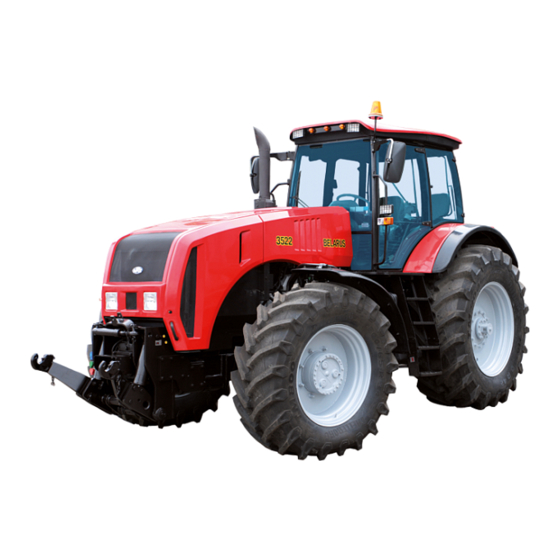
- Tractor
- 3522.5
- Operator’s manual
-
Contents
-
Table of Contents
-
Troubleshooting
-
Bookmarks
Related Manuals for Belarus 3522.5
Summary of Contents for Belarus 3522.5
-
Page 1
B E L A R U S 3 5 2 2 . 5 3522.5-0000010 OM OPERATOR’S MANUAL 2011 https://tractormanualz.com/… -
Page 2: Table Of Contents
1.1 Tractor assignment ………………………………………………………………….. 1.2 Technical specifications …………………………………………………………. 1.3 Tractor composition ………………………………………………………………… 1.4 Vibration level at the operator’s working place of the tractor “BELARUS-3522.5” 23 1.5 Noise level at the operator’s working place of the tractor “BELARUS-3522.5” 1.6 Tractor marking …………………………………………………………………..
-
Page 3
2.20.4 Cab hatch opening …………………………………………………………….. 2.21 Seat and its adjustments ………………………………………………………….. 2.21.1 General information ………………………………………………………………. 2.21.2 “BELARUS” seat adjustments ………………………………………………. 2.21.3 Seat installation for operation on reverse ……………………………………… 2.22 Connector elements of the electrical equipment ………………………… 2.22.1 Socket to connect coupled agricultural equipment …… -
Page 4
3522.5-0000010 РЭ 3.3 Clutch ……………………………………………………………………………….. 3.3.1 Coupling clutch …………………………………………………………………….. 3.3.2 Peculiarities of clutch installation, dismantling and adjustment ……… 3.3.2.1 Clutch arrangement ……………………………………………………. 3.3.2.2 Clutch dismantling …………………………………………………..… 3.3.2.3 Clutch installation …………………………………………………….. 3.3.2.4 Adjustment of clutch release levers ………………………….. 3.3.3 Clutch drive ……………………………………………………………………… -
Page 5
3522.5-0000010 РЭ 3.10.3 Check and Adjustment of Pneumatic System Pressure Regulator…… 3.11 Transmission Hydraulic System ……………………………. 3.11.1 General Information…………………………………………………. 3.11.2 Duplex Filter ………………………………………………………………….. 3.11.3 Magnetic Filter …………………………………………………………………. 3.11.4 Electrohydraulic Transmission Hydraulic System Distributor ……… 3.11.5 Rear PTO Control Distributor …………………………………….. -
Page 6
3.25.6 Outside mirror ………………………………………………………………….. 3.25.7 Roof with opening hatch ………………………………………………… 3.26 Front wheel fenders ……………………………………………………………… 3.27 Construction features of tractor BELARUS 3522.5 with non installed FLL and FPTO …………………………………………………………………………………… 3.27 Marking of tractor components …………………………..……………… 4 INTENDED USE OF TRACTOR ………………………………… -
Page 7
4.4.4 Technical maintenance after tractor run-in …………………………… 4.5 Actions in extreme conditions ……………………………………………….. 5 COUPLING OF IMPLEMENTS………………………………………………………….. 238 5.1 General Information ………………………………………………………………… 5.2 Types of implements coupled with tractor “BELARUS-3522.5” 5.3 Lift Linkage ………………………………………………………………….. 5.3.1 General Information ……………………………………………………………… 5.3.2 Three-Point Rear Lift Linkage ……………………………………… -
Page 8
3522.5-0000010 РЭ 6.4.7 Maintenance service that is inconsistent with the intervals of MS-1, 2MS-1, MS-2, MS-3 and special MS …………………………………………… 6.4.8 General maintenance services ……………………………………………….. 6.5 Safety measures during maintenance and repair operations………………… 6.5.1 General safety requirements ……………………………………………….… 6.5.2 Safety precautions for exclusion of the hazardous situations, related to the ac- cumulator battery and the fuel tank …………………………… -
Page 9
3522.5-0000010 РЭ https://tractormanualz.com/… -
Page 10
Introduction The present manual is designed for studying the structure, operation rules and maintenance of tractors “Belarus-3522.5”. Scrutinize this manual and operation manual of the engine TCD 7,8 L06, attached to your tractor. It will help you to study the rules of correct operation and maintenance. -
Page 11
3522.5-0000010 РЭ FLL – front lift linkage; SPIA – starting preheater of inlet air; FDAD – front driving axle drive; CM – control module; IICP – integrated indicator control module; IEP – integrated electronic panel; HPH – high pressure hoses;… -
Page 12
3522.5-0000010 РЭ The manufacturer uses standard international symbols, regarding application of in- struments and control units. Given below are the symbols with indication of their meanings. — see the manual ; — control manipulations; — brake; — fast; — manual brake;… -
Page 13
3522.5-0000010 РЭ — front screen wiper; — front driving axle drive; — rear screen wiper and — fan; washer; — brake fluid level in main cyl- — air filter clogged; inder tanks; — oil pressure in HSC — engine start;… -
Page 14
3522.5-0000010 РЭ FOR OPERATOR’S ATTENTION! Before going down to work on the tractor scrutinize the present Manual and Engine operation manual. Strictly observe all instructions on operation and mainte- nance. FORBIDDEN OPERATE TRACTOR WITHOUT FIRE- EXTINGUISHING AIDS. THE TRACTOR SHALL BE EQUIPPED WITH A FIRE FIGHTING TOOL –… -
Page 15
3522.5-0000010 РЭ IT IS FORBIDDEN TO MOVE ON REVERSE ON ROADS FOR PUBLIC USE AND AT WORKS, NOT RELATED TO AGRICULTURAL PRODUCTION! IT IS FORBIDDEN TO DRIVE THE TRACTOR WITH TWIN WHEELS ON ROADS FOR PUBLIC USE! ATTENTION: IT IS OBLIGATORY TO RUN-IN THE TRACTOR FOR 30 HOURS! -
Page 16: Tractor Description And Operation
The tractor “BELARUS-3522.5” is a general-purpose wheeled tractor with the wheel formula 4К4. Appearance of the tractor “BELARUS-3522.5” is presented in figures 1.1.1 and 1.1.2.
-
Page 17
3522.5-0000010 РЭ Figure 1.1.2 – Tractor “BELARUS-3522.5” (left and right views) https://tractormanualz.com/… -
Page 18: Technical Specifications
3522.5-0000010 РЭ 1.2 Technical specifications Main parameters and technical specifications of the tractor are given in table 1.1. Table 1.1 Parameter title Parameter value for the tractor (characteristics) “BELARUS-3522.5” 1 Rated traction force, kN 50 (60 2 Engine а) model…
-
Page 19
3522.5-0000010 РЭ Table 1.1 continued Parameter title Parameter value for the tractor (characteristics) “BELARUS-3522.5” 8 Distribution of operating weight on ax- les, kg: а) on front 4750±50 b) on rear 7100±110 9 Permitted load on axles, kN: a) on front… -
Page 20
3522.5-0000010 РЭ Table 1.1 finished Parameter title Parameter value for the tractor (characteristics) “BELARUS-3522.5” 19 Hydraulic system: а) pump displacement at crankshaft от 0 до 120 rated speed, l/min b) safety valve operation pressure, MPa 20,5±0,5 c) conventional volume factor, not less… -
Page 21: Tractor Composition
3522.5-0000010 РЭ 1.3 Tractor composition Tractor framework – frame-type. Undercarriage: front and rear driving wheels, with pneumatic tyres. Steering wheels are front wheels. The wheels are twinned by means of spacers. Rear wheels are twinned by means of spacers. Front wheels are twinned by means of clampbands.
-
Page 22
3522.5-0000010 РЭ PTO shaft end extension 1 (6 splines) under ISO 500 PTO shaft end extension 2 (21 splines) under ISO 500 The front PTO is continuous, single-speed with a PTO shaft end extension of type 2 (21 teeth). The direction of rotation is clockwise when viewed from the shaft end face. -
Page 23: Vibration Level At The Operator’s Working Place Of The Tractor «Belarus-3522.5
1.4 Vibration level at the operator’s working place of the tractor “BELARUS-3522.5” The vibration level at the operator’s seat complies with the Council Directive 78/764/ЕEС.
-
Page 24: Packing
3522.5-0000010 РЭ 1.7 Packing The tractor is dispatched to a consumer without packing. https://tractormanualz.com/…
-
Page 25: Controls And Instruments
3522.5-0000010 РЭ 2 Controls and instruments 2.1 Layout of controls and instruments of the tractor Controls and instruments, located in the tractor cab, are presented in fig. 2.1.1. Figure 2.1.1 – Layout of controls and instruments of the tractor https://tractormanualz.com/…
-
Page 26: Switches And Cuts-Out Of Instrument Board
3522.5-0000010 РЭ To the figure 2.1.1 – Layout of controls and instruments of the tractor: 1 – sun visor; 2 – cab light with switch; 3 – place for radio receiver (car stereo) installa- tion; 4 – conditioner control panel; 5 – upper shield unit of button switches; 6 – deflectors; 7 –…
-
Page 27
3522.5-0000010 РЭ Figure 2.2.2 – Layout of positions of starter and instruments disconnect switch ATTENTION: IF WITH THE ENGINE WORKING THE KEY OF THE STARTER AND INSTRUMENTS SWITCH IS TURNED INTO POSITION “0” – THE ENGINE WILL BE STOPPED! ATTENTION: THE REPEATED SWITCH-ON OF THE STARTER IS POSSIBLE ONLY AFTER RETURN OF THE KEY INTO POSITION “0”… -
Page 28: Upper Shield Unit Of Button Switches
3522.5-0000010 РЭ The windscreen wiper is activated by means of moving the underwheel switch lever 3 (fig. 2.2.1) from «off» position (“0” position according to fig. 2.2.4) into “a” position (low speed) or (high speed). All positions are fixed. The windscreen washer is activated (in a non-fixed position) by moving the switch lever upward from any of three positions of the switch.
-
Page 29: Conditioner Control
3522.5-0000010 РЭ Pressing the cut-out button 5 activates the rear screen wiper or the wiper and the washer of the rear screen simultaneously. The cut-out button 5 has three positions: — position “I” – “off”; — position “II” – “rear screen wiper is on” – fixed position;…
-
Page 30: Conditioner Control In A Heating Mode
3522.5-0000010 РЭ ATTENTION: THE AIR CONDITIONER CAN BE SWITCHED ON AND OPERATE ONLY WITH THE ENGINE ON! To switch on the conditioner it is required to do the following: turn the cut-out switch 2 (figure 2.4.1) clockwise to 180° until a blue scale be- gins;…
-
Page 31: Cab Ventilation
The scale of oil pressure gauge has three zones: — working — from 800 to 1500 kPa (green color); ATTENTION: FOR TRACTOR “BELARUS-3522.5” THE WORKING ZONE IS CONSIDERED A SCALE SECTION FROM 1300 TO 1500 kPa. WITH MINIMUM STABLE ENGINE SPEED OIL PRESSURE IN THE TRANSMISSION HYDRAULIC SYSTEM SHALL BE NOT LESS THAN 1000 kPa! — emergency (two) —…
-
Page 32
(figure 2.2.2) is set in position “I”. With the engine running the voltage gauge indicates voltage on generator ter- minals. A pilot lamp 4 is built in the scale of voltage gauge – on tractors “BELARUS- 3522.5” it is not used. -
Page 33: Pilot Lamps Unit
3522.5-0000010 РЭ 2.6 Pilot lamps unit The pilot lamps unit 14 (figure 2.1.1) includes five lamps. The allocation scheme is presented in figure 2.6.1. 1 – pilot lamp to indicate that the air cleaner filter is clogged to the max. (orange color);…
-
Page 34: Integrated Indicator And Integrated Indicator Control Panel
3522.5-0000010 РЭ 2.7 Integrated indicator and integrated indicator control panel 2.7.1 General information The integrated indicator 15 (figure 2.1.1) (hereinafter II) and the integrated indicator control panel 16 (figure 2.1.1) (hereinafter IICP) display information on operational pa- rameters of systems and units of the tractor and provide operator with data on violation of work or breakdown of any system.
-
Page 35: Assignment And Operation Principle Of Integrated Indicator Pointers
3522.5-0000010 РЭ change the mode of showing data entered on the multifunctional display with «Режим» (“Mode”) button. Rules on use of the IICP in the mode of displaying operational parameters and failure messages on the multifunctional display are given below in subsection 2.7.2 “Assignment and operation principle of II indicators”.
-
Page 36
3522.5-0000010 РЭ Table 2.2 – Correspondence of parameters of the indicator 3 (figure 2.7.1) to the speed of the rear PTO end extension Active annunciator of ranges of the rear PTO speed scale Upper (as per fig. 2.7.1) active segment of the Annunciator 6 “540 min… -
Page 37
3522.5-0000010 РЭ “Rear PTO speed”, and switching between messages on faults are effected with “Mode” button of the control panel (figure 2.7.2). Samples of displaying operating parameters of the tractor on the multifunctional display and their short description are given in table 2.3. -
Page 38: Pilot Lamps Of The Integrated Indicator
3522.5-0000010 РЭ Table 2.4 – Samples of displaying messages on tractor faults on the multifunctional display Parameter tested Sample of fault displaying Fault description on the Integrated Indicator In case there are no signals coming Testing worka- from the speed sensor for 10-12 sec. a…
-
Page 39: Description Of Testing Performance Of The Integrated Indicator
3522.5-0000010 РЭ — pilot lamp to indicate low level of coolant 16 get activated when the coolant level falls below the allowable threshold. ATTENTION: WHEN THE TRACTOR ON-BOARD SUPPLY VOLTAGE GOES UP ABOVE 19V THE INTEGRATED INDICATOR FULLY GOES OUT AND RECOVERES…
-
Page 40: Activation Of Changeable Images And Parameters On The Screen Of The Information Display
3522.5-0000010 РЭ 2.8.3 Activation of changeable images and parameters on the screen of the information display 1 – button to activate the main (three-segment) image and choose between induc- ible parameters; 2 – button to activate four-section image and choose between inducible parameters;…
-
Page 41
3522.5-0000010 РЭ Using the mode of choosing between inducible parameters the customer can acti- vate, if necessary, displaying of various engine parameters on the screen as per table 2.5. The mode of parameter choosing is activated after activation of the button panel with short-time pressing the button 5. -
Page 42
3522.5-0000010 РЭ Table 2.5 – Lift of parameters of four-segment and graphic indication of engine op- eration Four-segment imag- Graphic imag- Parameters Symbol Electric voltage directly on terminals of ü ü information monitor connection, V Voltage on the terminals of the ac- ü… -
Page 43: Integrated Electronic Panel
3522.5-0000010 РЭ 2.9 Integrated electronic panel 2.9.1 Assignment of IEP Control elements of electrohydraulic distributor 1 – annunciator of water presence in the fuel filter; 2 – annunciator of emergency oil pres- sure in the engine; 3 – maintenance annunciator; 4 – annunciator of fault testing; 5 – annunciator of activation an electronic foot fuel-feed pedal on forward motion;…
-
Page 44: Description Of Iep Performance Check
Figure 2.10.1 – reverse valve switch In HSC hydraulic system of “BELARUS-3522.5” tractors a reverse valve is installed which switches delivery of operating fluid from the feed pump to the dosing pump of forward motion or to the dosing pump of reverse motion.
-
Page 45: Steering Wheel Adjustments
3522.5-0000010 РЭ 2.10.3 Steering wheel adjustments 1 – steering wheel; 2 – chuck; 3 – handle to fix tilt of the steering column. Figure 2.10.2 – Steering wheel adjustment The steering wheel has the following adjustments: horizon tilt angle adjustment;…
-
Page 46: Pedals And Handle For Fuel Feed Manual Control
3522.5-0000010 РЭ 2.12 Pedals and handle for fuel feed manual control 2.12.1 Pressing the pedal 23 (figure 2.1.1) disengages the clutch. 2.12.2 Pressing the pedal 25 (figure 2.1.1) brakes the rear left wheel. 2.12.3 Pressing the pedal 26 (figure 2.1.1) brakes the rear right wheel. A joint plate of the brake pedals is intended for simultaneous braking with the right and left brakes.
-
Page 47
3522.5-0000010 РЭ The “braking” mode of the gearbox is engaged only when a symbol “P” (“Braking” is on) is displayed on the 7 (figure 2.13.4) located on CECS and corresponding segments of the first and sixth gear engagement of the annunciator 6 are on in a continuous mode. -
Page 48: Shifting Of Gears Inside Gearbox
3522.5-0000010 РЭ 2.13.2 Shifting of gears inside gearbox Gears are shifted by means of a joystick 6 (figure 2.13.1). The engaged gear is indi- cated by “0” gear annunciator 28 (figure 2.13.4) and respective segments of the annuncia- tor 6 and also by a digital indicator 7, all of them are installed in CECS.
-
Page 49: Creeper Control
3522.5-0000010 РЭ 2.13.3 Creeper control To switch on the creeper do the following: а) depress the clutch pedal; b) stop the tractor; c) set the gearbox to “0” gear; d) set the range switching lever 1 (figure 2.13.1) to neutral position;…
-
Page 50: Tractor Velocity Diagram
2.13.4 Tractor velocity diagram Velocity diagram for “BELARUS-3522.5” tractor with tyres 650/75R42 is presented in figure 2.13.3. Figure 2.13.3 – Velocity diagram for “BELARUS-3522.5” tractor with tyres 650/75R42 Velocity diagram for “BELARUS-3522.5” tractor with tyres 710/70R42 is presented in figure 2.13.3a.
-
Page 51: Complex Electronic Control System
3522.5-0000010 РЭ 2.13.5 Complex electronic control system 2.13.5.1 General information on assignment of complex electronic control system The complex electronic control system (CECS) on “BELARUS-3522.5” tractors is in- tended to perform the following functions: — indication of the gear engaged;…
-
Page 52: Indication Of The Engaged Gear And Gear Switching Mode Control
3522.5-0000010 РЭ In initial condition, when the operator shifts the starter and instrument switch into position ““I – instruments are on”, a middle mode of gear shifting is set by default – two upper segments light up on the indicator 9 (figure 2.13.4).
-
Page 53: Front Power Take-Off Shaft Control
3522.5-0000010 РЭ 2.13.5.4 Front power take-off shaft control Front PTO control is similar to RPTO control. The FPTO is controlled with buttons 3 and 32 (figure 2.13.4). Indication of RPTO operation is performed by annunciators 2, 33, 34. In initial condition, when the operator shifts the starter and instrument switch into position ““I –…
-
Page 54: Rear Axle Differential Lock Control
3522.5-0000010 РЭ If there is a necessity of FDAD positive engagement for short time, irrespective of tractor speed and front wheels turning angle, it is required to push button 25 and hold it pressed. FDAD remains engaged during holding the button 25 pressed. Simultaneously the annunciators 10 and 26 go off.
-
Page 55: Annunciation Of Emergency States Of Transmission And Hll Hydraulic Sys
3522.5-0000010 РЭ The mode of “RADL automatic control” is disengaged by repeated pressing the button 13 “AUTO” or by pressing and releasing the button of RADL positive engagement 22. Herewith the annunciators 12 and 21 will go out. If there is a necessity of RADL positive engagement for short time, irrespective of tractor speed and front wheels turning angle, it is required to push button 22 and hold it pressed.
-
Page 56: Diagnostics Of Electronic Systems Of Rpto, Fpto, Fdad, Radl Control, Gear Shifting Control For Failures
3522.5-0000010 РЭ 2.13.5.8 Diagnostics of electronic systems of RPTO, FPTO, FDAD, RADL control, gear shifting control for failures. In CECS the annunciators 6, 21, 24, 29, 34 (figure 2.13.4), except for indication of engaged state of a respective drive or a gear, perform diagnostics of the following failures…
-
Page 57: Rear Lift Linkage Control
3522.5-0000010 РЭ 2.14 Rear lift linkage control 2.14.1 General information RLL control is controlled with the control panel 31 (figure 2.1.1) and remote buttons 3 and 4 (figure 2.14.2). If there are failures in RLL electronic-hydraulic control system a di- agnostics annunciator 9 (figure 2.14.1) displays information on the failure and, if neces-…
-
Page 58
3522.5-0000010 РЭ The handle 7 has four positions: а) middle position – disengaged; b) upper position – uplift; c) lower position – lowering (in operation – automatic control); d) moving the handle downward (nonfixed) from “в” position – implement penetra- tion (herewith the automatic control is off);… -
Page 59: Remote Buttons Of Rll Control System
3522.5-0000010 РЭ To turn off the “dampening” mode press the button 10. The annunciator of “dampen- ing” deactivation will go out, and the RLL will return to its top position. Move the retainer 8 to its initial position. ATTENTION: THE “DAMPENING” MODE IS ACTIVE ONLY THE HANDLE 7 IS IN THE “UPLIFT”…
-
Page 60: Failure Diagnostics Of Rll Electronic Control System
3522.5-0000010 РЭ 2.14.4 Failure diagnostics of RLL electronic control system The electronic control system BOSCH, installed on your tractor, has an option of self-testing and whenever failures are detected it provides the operator with code informa- tion by means of failure diagnostics annunciators 9 (figure 2.14.1) on RLL control panel.
-
Page 61: Front Lift Linkage Control
3522.5-0000010 РЭ 2.15 Front lift linkage control The front lift linkage is controlled by the control panel 36 (figure 2.15.1) and remote buttons 1 and 2 (figure 2.15.1). If there are failures in electronic-hydraulic system of FLL control, the diagnostics annunciator 9 (figure 2.14.1) displays information on the failure and if necessary the FLL control system gets blocked.
-
Page 62: Electronic System Of Hydraulic Distributor Ehs Sections Control
3522.5-0000010 РЭ 2.16 Electronic system of hydraulic distributor EHS sections control. 2.16.1 General information on electronic system of hydraulic distributor EHS sections control Hydraulic distributor EHS sections control includes the following elements: — unit of electronic joysticks 35 (figure 2.2.1);…
-
Page 63: 2Unit Of Electronic Joysticks
3522.5-0000010 РЭ The electronic system operates in the following way. After the engine is started the sup- ply voltage is delivered to the operation programming unit of the hydraulic lift linkage (OPU of HLL) 33 (figure 2.2.1). OPU of HLL checks the control system elements for function and in- forms of the system state after the check is completed.
-
Page 64: Unit Of Electronic Joysticks «Bocoro
3522.5-0000010 РЭ The “floating” mode over section No 1 is activated by moving the handle of the joy- stick 1 forward against the stop and holding it in this position for more than two sec. The “floating” mode over section No 2 is activated by moving the handle of the joystick 1 to the right against the stop and holding it in this position for more than two sec.
-
Page 65: Operation Programming Unit (Opu) Of The Hydraulic Lift Linkage
3 and the button 2 by analogy with the abovestated. If “BOCORO” joysticks are available on “BELARUS – 3522.5” tractor it is possible to set the mode of fixed flow over a section of the hydraulic distributor only by means of pro- gramming OPU of HLL.
-
Page 66: Indication Of Operation Of The Hydraulic Distributor Ehs Sections When The Hydraulic Distributor Is Controlled Directly By Two Joysticks (Manual Mode)
3522.5-0000010 РЭ 1 – power disconnect switch of OPU of HLL; 2 – buttons to servo the set-up pro- gramms P1, P2, P3; 3 – annunciators of programs P1, P2, P3; 4 – annunciators of uplift of the corresponding hydraulic distributor EHS sections; 5 – annunciator of number of the ac- tive hydraulic distributor EHS section;…
-
Page 67
3522.5-0000010 РЭ Performing operations on control of implements connected to the hydraulic distribu- tor EHS sections, the OPU of the HLL allows to remember and reproduce operations, car- ried out before. The OPU of the HLL has a possibility to remember three different joystick manipulations. -
Page 68: Adjustment Of The Fixed Flow, Programmed With The Opu Of The Hll
3522.5-0000010 РЭ If during the program implementation you turn the power disconnect switch 1 (figure 2.16.6) of the OPU of the HLL into the disengaged position, the program implementation will be stopped and further control is possible only with joysticks. After the OPU power switch-on and repeated pressing of the button 2 the selected program will be started from the beginning.
-
Page 69: Flow Restriction
3522.5-0000010 РЭ 2.16.4 Flow restriction The electronic system controlling the hydraulic distributor EHS sections performs a function of “flow restriction” to drive coupled agricultural implements operating with less oil flow. The set-up function of “flow restriction” provides for more precise and smooth control at the given rates.
-
Page 70: Cutout Fuses
3522.5-0000010 РЭ 2.17 Cutout fuses Cutout fuses are intended for protection of electrical lines against overloads and short circuit. In the electrical line from the manual disconnect switch of the accumulator battery to the button switching the AB off there is a pendant 15 A fuse. In case this fuse is out of or- der it is possible to turn the AB on/off only with the manual switch.
-
Page 71: Switching Unit
3522.5-0000010 РЭ 2.18 Switching unit The switching unit 3 (figure 2.18.1) is intended for current supply, its distribution be- tween tractor power consumers and for protection of electrical lines against short-circuit and current load excess, it is a central distributing unit, to which wiring harnesses of differ- ent systems of tractor electrical equipment are connected by means of straps.
-
Page 72
3522.5-0000010 РЭ b) БК-1 1 – cutout fuse; 2 – signal led lamp of red color; 3 – signal led lamp of green color; 4 – electromagnetic relay; 5 – set of spare fuses. Figure 2.18.2 – Switching unit Diagram of fuses and relay location in the switching unit is presented in figure 2.18.3. -
Page 73
3522.5-0000010 РЭ Tables of fuses and relay assignment, presented in figure 2.18.3, are stuck from outside to the upper plastic cover 2 (figure 2.18.1) from the windscreen side. Information on fuses and relay assignment as well as fuse ratings are given in ta- bles 2.6 and 2.7. -
Page 74
3522.5-0000010 РЭ Table 2.7 – Relay assignment Relay desig- Relay assignament nation К1 Radioset (stereo-recorder) К2 Rear working lights (a pair of inner lights) К3 Conditioner К4 Rear working lights (a pair of outer lights) К5 Front working lights (on the roof) К6… -
Page 75
3522.5-0000010 РЭ Electrical connection of equipment harnesses to the swithing unit is presented in figure 2.18.5. Orange wire to Green wire to Power supply harness starter coil starter coil Dashboard harness Dashboard harness Harness of roof Harness of EE electrical EE… -
Page 76: Protection And Switching Unit
The protection and switching unit (PASU) is intended to distribute power supply be- tween tractor electronic control systems and to protect electrical lines from short circuit and current load excess. The tractor “BELARUS-3522.5” is equipped with a PASU of configu- ration БКЗ-3522.5.
-
Page 77
3522.5-0000010 РЭ Information on assignment and ratings of fuses and on relay assignment is given in tables 2.8 and 2.9, respectively. Electrical connection of harnesses of electronic control systems to slots Х1 ¸ Х6, Х8, Х9 (figure 2.19.2) and to outputs ХT1 ¸ ХТ3 of the PASU is presented in table 2.10. -
Page 78: Cab Locks And Handles
3522.5-0000010 РЭ Table 2.10 – Harness connection to PASU Slot Element connected (output) Х1 CECS harness Х2 Harness of engine electronic control system Х3 Harness of engine electronic control system Х4 Harness of FLL electronic control system Х5 Harness of RLL electronic control system Х6…
-
Page 79: Side Glass Opening
3522.5-0000010 РЭ 2.20.2 Side glass opening To open the side glass 1 (figure 2.20.2), right and left, rotate the handle 2 up and push it. Then fix the glass in opened condition, for this it is necessary to push the handle 2 down.
-
Page 80
3522.5-0000010 РЭ To close the hatch 1 pull the board 2 down until the hatch is fixed in a closed posi- tion. 1 – hatch; 2 – board; 3 – detent. Figure 2.20.4 – Opening of hatch with detent To open the hatch with the handle move the handle 2 (figure 2.20.5) down and push it up. -
Page 81: Seat And Its Adjustments
Figure 2.21.1 – “BELARUS” seat adjustments The “BELARUS” seat has the following adjustments: — adjustment according to the operator’s weight. It is carried out by means of a handle 1 (figure 2.21.1) within the range from 50 to 120 kg. To adjust the seat for a bigger weight it is re- quired to shift the pawl of the lever 1 into position “A”…
-
Page 82
3522.5-0000010 РЭ handle 2 up, move the seat and then release the handle. The seat will automatically get fixed in the required position. — the backrest tilt angle is adjusted by means of a handwheel 3 within the range from minus 30°… -
Page 83: Seat Installation For Operation On Reverse
3522.5-0000010 РЭ 2.21.3 Seat installation for operation on reverse on reverse on forward motion 1 – clamp; 2 – jaw; 3 – handle; 4 – clamp. Figure 2.21.2 – Seat installation for operation on reverse Seat installation for operation on reverse is carried out in the following order: — release clamps 1 (figure 2.21.2) and take them aside, exempting jaws 2 of the up-…
-
Page 84: Connector Elements Of The Electrical Equipment
2.22.2 Installation of electrical sockets Apart from the socket to connect a trailed agricultural equipment “BELARUS- 3522.5” tractors are equipped with additional electrical sockets. These sockets installation as well as cigar lighter installation is presented in figure 2.22.2. Power to the front socket 2 (figure 2.22.2), to the rear socket 5 and to the cigar lighter 4 is supplied after the accumulator battery is switched on.
-
Page 85: Reverse Post Controls
Figure 2.22.2 – Installation of electrical sockets and of cigar lighter 2.23 Reverse post controls “BELARUS – 3522.5” is equipped with a reverse control post with the aim to in- crease opportunities of coupling with front-mounted agricultural machines. Elements of the reverse control are as follows: — reverse motion steering column with a dosing pump;…
-
Page 86
3522.5-0000010 РЭ 1 – duplicated clutch pedal; 2 – additional disconnect switch of the rear screen wiper; 3 – reverse steering column; 4 – steering wheel; 5 – duplicated brake pedal; 6 – du- plicated fuel feed pedal; 7 – horn button; 8 – steering column of forward motion. -
Page 87
3522.5-0000010 РЭ To change a tilt angle of the reverse motion steering column 3 (figure 2.23.1) lo- cated on reverse post do the following: — pull the handle 2 up (figure 2.23.2); — tilt the reverse motion steering column 1 to a position comfortable for operation, and releasing the handle 2, swing the steering column smoothly in a longitudinal direction to reach a secure fixation. -
Page 88: Description And Operation Of Tractor Constituents
7 – bracket to mount the air cleaner. Figure 3.1.1 – Engine air cleaning system On “BELARUS-3522.5” tractors the system of cleaning the air, delivered to the en- gine turbocharger, includes: — air cleaner 1 (figure 3.1.1) with a built-in unit “multicyclone” of PSD (Donaldson) series;…
-
Page 89
3522.5-0000010 РЭ To reduce noise level in the cab, the air cleaner 1 is located in the underhood com- partment in the middle part of the engine assembly, just behind the turbocharger 3, with the outlet of the air intake 5 in underhood compartment. The air intake 5 is brought into coinci- dence with the upper hood cover 4. -
Page 90: System Of Charged Air Cooling
3522.5-0000010 РЭ 3.1.2 System of charged air cooling Intermediate cooling of charged air is a means, increasing density of air charge, coming to engine cylinders, thus enabling more effective burning of fuel in the cylinders and as a result ensuring increase of power with decrease of specific fuel consumption. An air-cooled cooling system is used in engine, with a plate-fin air cooler (radiator) 1 (figure 3.1.3), mounted in front of the water radiator on the CAC lifting mechanism 6.
-
Page 91: Cooling System
3522.5-0000010 РЭ 3.1.4 Cooling system The system of engine cooling is a liquid closed-type, with forced coolant circulation and a deaerating-compensation circuit. It includes a cooling jacket, a water pump, a radia- tor with in-built deaeration system, a fan with an automatically controlled viscous clutch, an expansion tank, connection hoses, clamps, drain plugs, a plug of the expansion tank with a steam and air valves.
-
Page 92: Exhaust System
Figure 3.1.5 – Exhaust system “BELARUS-3522.5” exhaust system consists of an inlet pipe 7 (figure 3.1.5), a system of selective catalytic reduction and an exhaust pipe 5. The system of selective catalytic reduction (SCR) is intended to ensure a required chemical composition of exhaust gas under Stage Tier-IIIB in the exhaust system.
-
Page 93
3522.5-0000010 РЭ The SCR operation principle is based on reduction of nitrogen oxide (NOx) level in exhaust gases to reach a required level. For this reason AdBlue agent is injected in the mixing pipe 6 in front of the SCR catalyst 3 by means of the dosing module 12. The location of the dosing module, dimen- sions and form of the mixing pipe ensure max. -
Page 94: Engine Electronic Control System
3522.5-0000010 РЭ 3.2 Engine electronic control system The engine electronic control system (EECS) is powered directly by the accumulator battery through two 30 A fuses which are located in the PASU. The EECS electical connection diagram is presented in figure Б1 of the Annex B (basic units of the electrical part of SCR system are given on sheet 2 of figure Б1 in Annex…
-
Page 95
3522.5-0000010 РЭ https://tractormanualz.com/… -
Page 96
3522.5-0000010 РЭ Table 3.1 – Description of EECS response to decrease of urea level Indication on the information display Response of the Urea level Symbol of Symbol warning of Availability of engine control in the tank urea level low urea level… -
Page 97
3522.5-0000010 РЭ 1 – feeding module; 2 – catalyst; 3 – NOx sensor after catalyst; 4 – sensor of ex- haust gas temperature in front of a catalyst; 5 – NOx sensor in front of a catalyst; 6 – sen- sor of urea temperature and level in the tank;… -
Page 98
3522.5-0000010 РЭ 1 – delivery hose; 2 – NOx sensor before catalyst; 3 – sensor of exhaust gas tempera- ture before catalyst; 4 – dosing module; 5 – SCR system harness; 6 – module of NOx sensor before catalyst; 7 – catalyst. -
Page 99: Clutch
3522.5-0000010 РЭ 3.3 Clutch 3.3.1 Coupling clutch A dry-friction double-disk spring-loaded coupling clutch is mounted on the engine flywheel through a spacer. The clutch driving part is a flywheel 1 (figure 3.3.1), a pressure plate 4 and a center plate 3, having four tenons on outer surfaces, which intrude into special mortises of the spacer 23.
-
Page 100: Peculiarities Of Clutch Installation, Dismantling And Adjustment
3522.5-0000010 РЭ 3.3.2 Peculiarities of clutch installation, dismantling and adjustment 3.3.2.1 Clutch arrangement Workholder 4 manufacturing bolts M12x65 1 – driven disk; 2 – center plate; 3 – bolt; 4 – driven disk; 5 – pressure plate; 6 – bolt;…
-
Page 101: Clutch Dismantling
3522.5-0000010 РЭ 3.3.2.2 Clutch dismantling Clutch is dismantled after the engine has been detached from the transmission in the following order: — mount four manufacturing bolts (M12x65), having screwed them into the pressure disk 5 (figure 3.3.2) through the manufacturing orifices of the back plate 7;…
-
Page 102
3522.5-0000010 РЭ 1 – tank; 2, 21, 26, 31, 37 – piston; 3 – sensor of clutch disengaged state on for- ward; 4, 16 – bolt; 5, 8, 17, 24, 39, 49 – nut; 6, 15 – fork; 7 – pin; 9, 22, 33, 38 – pusher;… -
Page 103: Clutch Control Adjustment
3522.5-0000010 РЭ 3.3.4 Clutch control adjustment 3.3.4.1 Clutch control adjustment The clutch control is adjusted in the following order: 1. Adjusting of a clearance gap “B” (figure 3.3.4) between the piston 2 and the pusher 9 of the main cylinder 12 (for forward motion): — set the pedal 10 so as to observe “D”…
-
Page 104: Bleeding Of The Hydraulic System Of Clutch Operating Control
3522.5-0000010 РЭ — if the value of piston projection is different, do the following: — unlock the spherical nut 40; — screwing the spherical nut 40 in or out, attain the dimension “M” for piston 37 pro- jection when depressing the pedal 10;…
-
Page 105: Gearbox
3522.5-0000010 РЭ 3.4 Gearbox 3.4.1 General information The gearbox is mechanical with constant-mesh gears of a range type, it provides twenty four speeds for the front motion and twelve speeds for the reverse, continuous PTO and FDA drives. The ranges are shifted by means of gear clutches with use of the coupling clutch, and the speeds are shifted by means of electro-hydraulically operated friction clutches without use of the coupling clutch.
-
Page 106
3522.5-0000010 РЭ 1, 16 – packing; 2, 14 – cage; 3, 5, 12, 48 – ring; 4, 11, 49 – cover; 6 –shaft; 7, 10 – collar; 8, 18, 23, 26 – needle bearing; 9 – bracket; 13 – plug; 15 – sealing ring; 17, 24, 27, 29, 33, 38, 41, 43, 45, 46, 47 –… -
Page 107: Range Shifting Reduction Unit
3522.5-0000010 РЭ Driving disks 13 are mounted in drum grooves, and in between there are metal- ceramic driven disks 12 with inner splines. The disk packs are completed with bearing disks 11, fixed by lock rings 2. Arrangement of the friction clutch 25 is identical with the arrangement of the friction clutch 21.
-
Page 108
3522.5-0000010 РЭ 1 – cover; 2, 4, 6, 8, 10, 13, 14, 18, 22, 25 – bearings; 3, 17, 20, 26, 27, 31 – gears; 5, 15, 16, 21 – sleeve; 7 – body; 9, 29 – gearwheel unit; 11 – PTO drive shaft; 12 – input shaft;… -
Page 109
3522.5-0000010 РЭ Marking place Place for marking a serial num- ber and branding (Range shifting forks) 1, 2 – covers; 3 – switch of engine start-up lock; 4 – pipeline; 5, 9 – bearings; 6 – reverse shaft; 7, 8 – gears; 10, 11 – forks; 12, 13, 14, 15 – carriers; 16 – balls. -
Page 110
3522.5-0000010 РЭ The gears 20 (figure 3.4.3) and 17 provide creeper operation in mesh with the gear 26 and the toothed rim of the creeper shaft 24. The creeper shaft 24 is mounted on the bearings 25 and 22, located in bores of the cage 3. -
Page 111
3522.5-0000010 РЭ https://tractormanualz.com/… -
Page 112: Electrical Part Of Gearbox Control
3522.5-0000010 РЭ 3.5 Electrical part of gearbox control Speed shifting is controlled by means electronic-hydraulic control system. The electrical part of speed shifting system consists of CECS electric unit 1 (figure 3.5.1), a gear shifting joystick 3, which are located in the cab to the right of the operator; of a button 14 to set up gearbox braking mode, located on the handle of the range shifting lever;…
-
Page 113
3522.5-0000010 РЭ https://tractormanualz.com/… -
Page 114
3522.5-0000010 РЭ ATTENTION: AFTER FINISHING ADJUSTMENTS IN CLUTCH DISENGAGEMENT DRIVE, CHECK RESPONSE ADJUSTMENT OF SENSORS OF CLUTCH DISENGAGED STATE ON FORWARD MOTION AND ON REVERSE! Adjustment of the sensor 1 (figure 3.5.2) actuation shall be carried out with the en- gine running. -
Page 115
3522.5-0000010 РЭ The sensor of clutch disengaged state on reverse 2 (figure 3.5.3) is adjusted by way of turning the bracket 1 together with the sensor 2 in the slot in the bracket. The adjust- ment shall be carried out with the engine running. After adjustment with the clutch fully… -
Page 116: Rear Axle
3522.5-0000010 РЭ 3.6 Rear axle 3.6.1 General information The rear axle consists of a main gear, a differential with locking mechanism, final drive gears and brakes, arranged in one body. A reduction part is located in the front section of the rear axle body, it consists of…
-
Page 117: Differential
3522.5-0000010 РЭ 3.6.3 Differential Differential body Lock body Differential cover 1 – differential bolts; 2 – locking plates of differential bolts; 3 – sleeves; 4 – axle- shaft gears; 5 – spider pinions; 6 – rollers; 7 – differential center cross; 8 – differential cover;…
-
Page 118: Final Drives
3522.5-0000010 РЭ 3.6.4 Final drives The final drives (figure 3.6.3) are planetary gear reducers with double-rim satellite gears 21 and floating crown gears 20. The drive (sun) gears 22 and 39 with brake hubs 23 are connected with differential axle shaft gears by means of splines. Each sun gear is meshed with toothed rims (z=42) of three double satellite gears by means of its toothed rim (z=15).
-
Page 119
3522.5-0000010 РЭ 1, 6, 7 – gear; 2,3,5,8– sleeve; 4 – clutch; 9 – pin of epicycle hub; 10 – carrier; 11; 12 – axle shaft bearings; 13 – toothed disk; 14 – speed sensor; 15 – axle shaft; 16 –… -
Page 120: Check And Adjustment Of Play In Differential Tapered Bearings
3522.5-0000010 РЭ 3.6.6 Check and adjustment of play in differential tapered bearings Axial play in the differential tapered bearings shall be 0,1 to 0,15 mm. Trying shims 2 (figure 3.6.4) under a cover 1, and if necessary under a cover 4, adjust bearing play.
-
Page 121: Check Of Main Drive Gears For Accuracy Of Engagement According To Contact Pattern
3522.5-0000010 РЭ ATTENTION: CAST IRON RINGS 5 (FIGURE 3.6.5) SHALL BE MOUNTED (IN ORDER TO PREVENT RING DAMAGE DURING ADJUSTMENTS) AFTER ALL AD- JUSTMENTS HAVE BEEN CARRIED OUT WITH THE FINAL MOUNTING OF THE COVER 4! 1 – left cover; 2 – shims; 3 – plate ready-assembled with drive master pair; 4 – right cover;…
-
Page 122: Check And Adjustment Of Backlash In Tapered Gears With Circular Teeth To Drive Pumps Of Hhl And Transmission Hydraulic System
3522.5-0000010 РЭ 3.6.9 Check and adjustment of backlash in tapered gears with circular teeth to drive pumps of HHL and transmission hydraulic system. The backlash in tapered bearings shall make 0,2 to 0,4 mm. The contact shall be not less than 50 % of the surface with impress location in the middle part. The adjustment shall be carried out by means of changing the number of shims 2 under the body of pump drive 1 (figure 3.6.7).
-
Page 123: Check And Adjustment Of Axial Clearance In Bearings Of Cage Of Back Rest For Drive Gear-Shaft Of The Master Pair
3522.5-0000010 РЭ 3.6.11 Check and adjustment of axial clearance in bearings of cage of back rest for drive gear-shaft of the master pair The axial clearance in the bearings shall not exceed 0,1 mm. The adjustment shall be carried out by means of changing the number of shims 2 (figure 3.6.6). When carrying out ad- justment turn the cage 3 to make rollers take their position in the cage.
-
Page 124: Rear Power Take-Off Shaft
3522.5-0000010 РЭ 3.7 Rear power take-off shaft Economy mode Basic mode 1000 rpm under 1435 1000 rpm under 2000 rpm of rpm of engine speed engine speed 1 – spline coupling; 2 – friction clutch thrust disk; 3 – friction clutch drive disk; 4 – driven disk;…
-
Page 125
3522.5-0000010 РЭ The rear power take-off shaft (PTO) (figure 3.7.1) has a separate 1000 rpm drive of the end extension for two modes – basic and economy. The torque to the rear PTO is transferred from the engine by means of connecting shafts and splined bushings in the gearbox and in the rear axle body. -
Page 126: Front Power Take-Off Shaft
3522.5-0000010 РЭ 3.8 Front power take-off shaft The front power take-off shaft (FPTO) is intended to drive agricultural machines with active working attachments, located on the front lift linkage. The front PTO provides 1000 rpm of shaft end extension speed under (2100 ± 50) rpm of the engine crankshaft speed with 60 kW of power implementation.
-
Page 127
3522.5-0000010 РЭ https://tractormanualz.com/… -
Page 128: Brakes
3.9 Brakes 3.9.1 General Information The tractors BELARUS — 3522.5 are equipped with the disk brakes working in the oil bath. 1 – casing; 2 – cover; 3 – pressure disk; 4 – coupling springs; 5 – expanding balls; 6 –intermediate disk;…
-
Page 129
3522.5-0000010 РЭ https://tractormanualz.com/… -
Page 130: Brakes Drive Mechanisms
3522.5-0000010 РЭ To the figure 3.9.2 –Brakes control scheme: 1 – locking nut; 2 – push rod; 3 – pipeline; 4 – main cylinder for forward motion; 5 – tank; 6 – spring; 7 – bolt; 8 – nut; 9 – forward motion pedal; 10 – push rod; 11 – pin; 12 – fork;…
-
Page 131
3522.5-0000010 РЭ The brakes control includes manual control by lever 1 (figure 3.9.4) through the sys- tem of rods and levers and brakes drive mechanisms “Б” and “В”(figure 3.9.3). 1 – control lever; 2 –left lever; 3 –external lever; 4 – control rod; 5 –intermediate rod;… -
Page 132: Independent Mechanical Parking Brake
3522.5-0000010 РЭ 3.9.4 Independent Mechanical Parking Brake As parking brake is used service brake with independent hand rear wheel drive. The independent mechanical parking brake consists of: lever 1 (figure 3.9.5) mounted on bushings 2 on axle 3, tightened with nut 4 in bracket consisting of side members 5, 6, sec- tor 7, distance pieces 8 and coupling bolts 9 with nuts 10.
-
Page 133: Brake Operation With Forward Pedal Drive
3522.5-0000010 РЭ 3.9.5 Brake Operation with Forward Pedal Drive When pressed on brake pedal, the push rod 6 (figure 3.9.6) of main brake cylinder con- nected with pedal lever moves forward. Meanwhile is closed the lock valve 4 through which in casing 1 arrives brake fluid from tank.
-
Page 134: Adjustment Of Brake Controls At Forward Motion
3522.5-0000010 РЭ 3.9.7 Adjustment of Brake Controls at forward motion Check and adjust brake controls at forward motion in the following order: 1. Set the pedal pads 9 (figure 3.9.2) in one plane with a help of stop bolts 7, screw them at depth 20±3 mm.
-
Page 135: Adjustment Of Brake Controls On Reverse
3522.5-0000010 РЭ 3.9.8 Adjustment of Brake Controls on reverse Check and adjust brake controls at reverse motion in the following order: 1. Adjust clearance between the piston 13 (figure 3.9.2) and the push rod 10 of pis- ton of main brake cylinder 14, therefore disconnect the fork 12 from the pedal 15 and turn-…
-
Page 136: Pneumatic System
3.10 Pneumatic System 3.10.1 General information The tractor BELARUS-3522.5 is equipped with the combined pneumatic drive pro- viding brake control of trailers and agricultural machines, equipped both with single-wire and with two-wire pneumatic brake drive. The pneumatic drive is used also for tires charg- ing and other purposes where energy of compressed air is required.
-
Page 137: Check And Adjustment Of Pneumatic System Brake Valves Actuators
3522.5-0000010 РЭ In the pneumatic drive are installed the connecting heads 1, 15, 16 of valve type. The valves of connecting heads prevent air outlet, if pneumatic drive is used without trailer (for example, tire charging) and at emergency trailer disconnection. At connection of the trailer brake lines with tractor lines the valves of connecting heads open, providing passage of the compressed air from tractor pneumatic drive to the trailer.
-
Page 138: Check And Adjustment Of Pneumatic System Two-Wire Brake Valve Actuator
3522.5-0000010 РЭ Check and if necessary adjustment of pneumatic system single-wire brake valve ac- tuator «A» (figure 3.10.2) should be made after adjustment operations of pedal brakes and control adjustments of parking brake. ATTENTION: MAKE ADJUSTMENT OF SINGLE-WIRE BRAKE VALVE ACTUA-…
-
Page 139
3522.5-0000010 РЭ Check and, if it is necessary, adjustment of the brake valve actuator «Б» (fig- ure 3.10.2) of two-wire pneumatic drive should be made in the following order: — attach manometer with scale not less than 1 MPa to connecting head (with yellow cover) of tractor pneumatic drive;… -
Page 140: Check And Adjustment Of Pneumatic System Pressure Regulator
3522.5-0000010 РЭ 3.10.3 Check and Adjustment of Pneumatic System Pressure Regulator It is necessary to adjust pneumatic system pressure regulator during maintenance No 3 (M3), also if pressure regulator operation is disturbed and also after its disassembly for washing or replacement of worn out parts.
-
Page 141: Transmission Hydraulic System
3522.5-0000010 РЭ 3.11 Transmission Hydraulic System 3.11.1 General information Hydraulic circuit diagram is shown in figure 3.11.1. А1 –mesh filter; А2 – duplex filter; А3 – oil unit; А4 – electrohydraulic distributor; А5 – gear shift group; А6 –assembled coupling hydraulic booster; А7 –rear PTO control; А8 –…
-
Page 142
3522.5-0000010 РЭ The location of transmission hydraulic system components is shown in figure 3.11.2. а) view from the right б) view from above 1 – rear PTO bearings lubrication line ; 2 – rear PTO control distributor; 3 – transmission hydrau- lic system (HS) pump;… -
Page 143
3522.5-0000010 РЭ The transmission hydraulic system, besides power shifting, provides power fluid fil- tration, lubrication of most loaded gears and transmission bearings under pressure, con- trols front and rear power take off(PTO)shaft, front driving axle (FDA) drive, rear axle dif- ferential lock and coupling clutch. -
Page 144: Duplex Filter
3522.5-0000010 РЭ 3.11.2 Duplex Filter The duplex filter, mounted on silencer support to the right along tractor movement, is intended for clarification of oil pumped by transmission pump with filtering capacity of 0,025 mm, and also for pressure maintenance in transmission hydraulic system.
-
Page 145: Magnetic Filter
3522.5-0000010 РЭ 3.11.3 Magnetic Filter The magnetic filter (figure 3.11.4), intended for oil separation from ferromagnetic particles of transmission hydraulic system. It is situated to the right along tractor movement on GB cover of creeper control. The filter consists of the case 2 on which is mounted cover 1 with four magnet traps 3.
-
Page 146: Rear Pto Control Distributor
3522.5-0000010 РЭ 3.11.5 Rear PTO Control Distributor The rear PTO control distributor is intended for rear PTO engagement and disen- gagement. The distributor consist of casing 1 (figure 3.11.6), in which are situated the spring loaded valve core 2, electrodriven proportional valve 3 and pressure sensor 4.
-
Page 147: Front Driving Axle (Fda)
3522.5-0000010 РЭ 3.12 Front Driving Axle (FDA) 3.12.1 General information 1 –wheel hub drive; 2 –shim washer; 3 –spring washer; 4 – bolt; 5 – cap; 6 –oiler; 7 – ring; 8 – fixture; 9 – bearing; 10 – spacer; 11 – bearing; 12 – semiaxle shaft; 13 – FDA hous- ing;…
-
Page 148: Central Reduction Unit
3522.5-0000010 РЭ The fixture 8 with sealing 33 and rubber rings 7 serves for prevention of oil leakage from FDA housing along universal-joint fork 34. In axle housing 13 doubled universal joint is fixed by locking ring 30 and locking screws 43 The semiaxle shaft 12 with double-sided splines is mounted between the doubled joint and central reduction unit differential.
-
Page 149
3522.5-0000010 РЭ The nuts 8 also serve for main gear pair gearing adjustment and for necessary tooth- contact pattern assurance. The stop members 31 attached to bearing bodies 27 by bolts 33 through spring washers 32 fix nuts 8. 1 – bolt; 2 –bend off plate; 3 –differential housing;4 – side gear; 5 – spring seat; 6 –… -
Page 150: Wheel Hub Drive
3522.5-0000010 РЭ 3.12.3 Wheel hub drive 1 – plug; 2 – bolt; 3 – carrier; 4 –sun gear; 5 – bushing; 6 – planetary gear; 7 — backup washer; 8 – planetary gear shaft; 9 – sealing ring; 10 – roller; 11 –washer; 12 –…
-
Page 151: Check And Adjustment Of Preload In Conical Bearing Of Reduction Unit Drive Gear
3522.5-0000010 РЭ Both rows of rollers are divided by washer 11. As one roller race serve grinding sur- face of axis 8, and as another –inner grinding surface of planetary gear 6. The planetary gears and roller are locked from axial movement with washers 7. The planetary gear axles are fixed from axial movement in carrier seat with pins 13.
-
Page 152: Check And Adjustment Of Preload In Differential Conical Bearings
3522.5-0000010 РЭ 3.12.5 Check and Adjustment of Preload in differential conical bearings The axial preload in differential conical bearings should be between 0,01 and 0,08 It is necessary to make adjustment by nuts 2 tightening (figure 3.12.5). The axial bearings preload should correspond to moment of differential rotating resistance between 0,6 and 6 Nm.
-
Page 153: Check And Adjustment Of Backlash (Preload) In Conical Bearings Of Hub
3522.5-0000010 РЭ 3.12.7 Check and Adjustment of Backlash (Preload) in Hub Conical Bearings The axial backlash or preload in hub bearing should not exceed 0,05 mm. Please adjust with a help of shim washers 2 (figure 3.12.6). At bolts 3 tightening turn over hub 1, so that bearing rollers have taken correct position in race.
-
Page 154
3522.5-0000010 РЭ The force applied to the carrier mounting bolts should be between 140 and 160 N. . It is necessary to repeat force check operation three times in each direction to determine average value. If force of wheel hub drive turning is under 60 N, before pivot bearings 36 preload adjustment it is necessary to dismount bottom axle 37 and to check technical condition of bottom pivot bearing. -
Page 155: Front Driving Axle Drive
3522.5-0000010 РЭ 3.12.9 Front Driving Axle Drive А – oil feed channel, Б – clutch booster; 1 – flange; 2,5 – bearings; 3 – rings; 4,6,8 – rings; 7 – sleeve; 9 – piston; 10 – spring; 11, 12 – disks; 13 – drum; 14, 15 – couplings; 16 – torsion bar;…
-
Page 156: Cardan Shaft
3522.5-0000010 РЭ The gear 3 (figure 3.12.8) is mounted on shaft 4 splines and is in constant mesh with gear 2 located in rear axle. The shaft 4 is mounted on rear axle case on ball bearings 1 and 5 and through spline couplings 15, 14 (figure 3.12.7) is connected by torsion bar 16 with driving disks 11.
-
Page 157: Electronic System For Rear-Axle Differential Lock Control, Front Driving Axle Drive Control, Front And Rear Power Take Off Shafts Control
3522.5-0000010 РЭ 3.13 Electronic system for rear-axle differential lock control, front driving axle drive control, front and rear power take off shafts control 3.13.1 Rear-axle Differential Lock Control The rear-axle DL is controlled by electrohydraulic system. The electronic part of DL is a part of complex control system and consists of electronic unit CECS 1 (figure 3.13.1),…
-
Page 158
3522.5-0000010 РЭ https://tractormanualz.com/… -
Page 159: Fda Drive Control
3522.5-0000010 РЭ 3.13.2 FDA drive control The FDA drive is controlled by electrohydraulic system. The electronic part of FDA drive control system is a part of complex control system and consists of electronic unit CECS 1 (figure 3.13.1), located in cabin on the panel to the right of the driver; of wheel turning an- gle sensor 12 mounted on the right side on FDA;…
-
Page 160: Front Pto Shaft Control
3522.5-0000010 РЭ ATTENTION: AT WIRE BREAKAGE IN THE CONTROL CHAIN OF FDA DRIVE ELECTROMAGNET THE FDA DRIVE AUTOMATIC SWITCH ON, INDEPENDENT OF THE SET MODE (INCLUDING MODE “FDA DRIVE IS SWITCHED OFF)! 3.13.3 Front PTO shaft control The front PTO shaft is controlled by the electronic hydraulic system. The electronic part of front PTO control system is a part of complex system of DL, FDA, PTO and gear shifting control and consists of CECS unit 1(figure 3.13.1), located in cabin on panel to the…
-
Page 161
3522.5-0000010 РЭ The distributor 6 controls oil flow, that is supplied to hydraulic coupling of rear PTO drive engagement. The discrete pressure sensor 5, that is active (contacts closing) under pressure above 0,6…0,8 MPa, is installed in hydraulic line for oil supply from dis- tributor 6 to hydraulic coupling of rear PTO drive engagement. -
Page 162: Undercarriage And Tractor Wheels
— 18.4R34– main front tires; — 520/70R34– additional front tires, for doubling of front wheels. It is technically permissible to mount on tractors BELARUS -3522.5 rear tires 710/70R42 (single as well as doubled) and front tires 600/65R34 (tires 520/70R34 – for doubling).
-
Page 163: Hydrostatic Steering Control
3522.5-0000010 РЭ 3.15 Hydrostatic Steering Control 3.15.1 General information The hydrostatic steering control (HSC) is intended for control of guide wheels turn, for steering effort decrease at tractor turning. HSC consists of two dosing pumps 2 and 3 (figure 3.15.1), of reverse valve switch 4, of two differential hydraulic cylinders 1, making turning, of feed pump 5 with motor drive and of hydraulic fittings.
-
Page 164: Dosing Pump
3522.5-0000010 РЭ Reverse valve switch 4 (figure 3.15.1) is installed for the purpose of HSC operation as well as by forward motion of the tractor and by reverse motion. Reverse valve 4 is mounted to the left under the hood at driver’s cab on the left post of hood fixation bracket. The reverse valve 4 is controlled by shifting the handle into one of two positions until it gets fixed in one of them.
-
Page 165: Steering Hydraulic Cylinder
3522.5-0000010 РЭ The protective valve 6 limit maximal pressure in delivery line within the limits of 17,5… 18,0 MPa. The anti-shock valves 7 limit pressure in cylinder lines in impact condi- tions. Pressure of anti-shock valves should be adjusted between 22 and 23 MPa.
-
Page 166: Hydraulic Lift Linkage (Hll)
3522.5-0000010 РЭ 3.16 Hydraulic lift linkage (HLL) 3.16.1 General information The hydraulic lift linkage operates front and rear lift linkages and hydraulic working attachments of agricultural implements coupled with a tractor. Rear lift linkage is controlled by regulator with electromagnetic control, that ensure draft, position, combined and depth control during operation with mounted and semi-mounted implements.
-
Page 167
3522.5-0000010 РЭ 1 – electrohydraulic unit with EHS sections, end control plate and ЕНR23-LS; 2 – oil tank; 3 – hydraulic cylinders Ц110х250; 4 –fast coupling (FC); 5 – hydraulic cylinder drain- age; 6 – uplift outputs (red protective plug); 7 – lowering outputs (green protective plug); 8 –… -
Page 168
3522.5-0000010 РЭ https://tractormanualz.com/… -
Page 169
3522.5-0000010 РЭ https://tractormanualz.com/… -
Page 170
3522.5-0000010 РЭ FLL control RLL control Valve Drain from HSC Free drain Oil tank HSC suction Figure 3.16.4 – HLL hydraulic circuit diagram https://tractormanualz.com/… -
Page 171
3522.5-0000010 РЭ https://tractormanualz.com/… -
Page 172: Oil Tank
3522.5-0000010 РЭ 3.16.2 Oil tank The tractor is mount with integrated oil tank of LL and HSC systems with a capacity of 100±0,5 l , this tank is equipped with breather 1 (figure 3.16.6) with changeable paper element. On front wall of oil tank are made two joints for free-flow pump drain and for EHR-5LS drain of FLL control.
-
Page 173: Distributor
3522.5-0000010 РЭ 3.16.4 Distributor 3.16.4.1 General information The tractors BELARUS-3522.5 are equipped with integrated block, which consists of four distributive sections of EHS type, of electrohydraulic regulator EHR-23LS, of end plate with pressure reducing valve and of discharge cover. Distributive section EHS represent integrated product that consists of hydraulic and electronic part.
-
Page 174
Figure 3.16.9 –Diagram of directive valve positioning and centre slide-valve posi- tioning at performance of different functions. Version of programmed flow regulation curve for tractors BELARUS-3522.5 is shown in figure 3.16.10. PWM rate Figure 3.16.10 – Dependence of working liquid flow at outlet from SB 23LS-EHS distributor sections on control signal value at control by means of joysticks. -
Page 175: End Control Plate Of Ehs Working Sections
3.16.5 Hydraulic system of FLL control 3.16.5.1 General information The tractors BELARUS-3522.5 are equipped with automatic control system of front lift link- age (FLL), using position control method. As actuator is used electrohydraulic regulator EHR-5LS of the company Bosch, its design and basic circuit diagrams are shown in figure 3.16.12. As position sensor is used angular sensor of the same company with angle ±…
-
Page 176: Installation And Adjustment Of Fll Position Sensor
3522.5-0000010 РЭ 3.16.5.2 Installation and adjustment of FLL position sensor As far as front lift linkage with position control doesn’t have positive down movement, it is better to load front lift linkage additionally with weight 150…2500 kg for convenience by position sensor adjustment.
-
Page 177
3522.5-0000010 РЭ 3. Start the engine. Lift up the handle 1 of lift linkage control (figure 3.16.5), when this happens annunciatior 2 of FLL uplift should shine redly. At the end of uplift the an- nunciator 2 should go out. In maximal raised position of FLL is allowed reflector zone value of cylinder rod between 1 and 10 mm. -
Page 178: Electrical Curcuit Diagram Of Section Distributor Ehs Control
3522.5-0000010 РЭ 3.16.6 Electrical curcuit diagram of section distributor EHS control. Electrical curcuit diagram of section distributor EHS control of tractors BELARUS- 3522-5 (modifications with electronic joystick unit BOCORO and with electronic joystick unit EJU-1) is shown in figure 3.16.17.
-
Page 179
3522.5-0000010 РЭ https://tractormanualz.com/… -
Page 180: Emergency Conditions Indication Of Hydraulic Lift Linkage And Transmission Hy- Draulic System
3522.5-0000010 РЭ 3.17 Emergency conditions indication of hydraulic lift linkage and transmis- sion hydraulic system. At clogging of duplex filter used for oil clearing in transmission hydraulic system goes on sensor 3 (figure 3.17.1), on faceplate of CECS panel flashes on annunciatior 4.
-
Page 181: Rear Lift Linkage
3522.5-0000010 РЭ 3.18 Rear Lift Linkage 3.18.1 General information 1 – bracket of turning shaft; 2 – turning shaft; 3 – lever (left and right by 1 pcs.); 4 – hydraulic cylinder (2pcs.); 5 – crossbeam (2pcs.); 6 – top link; 7 – draft link (left and right by 1 pcs.);…
-
Page 182: Drawbar
3522.5-0000010 РЭ 3.18.2 Drawbar The drawbar 9 (figure 3.18.1) is fixed by one end to eyelets 8 of draft links 7. The other end of drawbars with pivot is installed in brackets of drawbars 12. The brackets of drawbars 12 are fastened on the bottom part of rear axle tubes.
-
Page 183: Electronic Control System Of Rear Lift Linkage
3522.5-0000010 РЭ 3.19 Electronic control system of rear lift linkage 1 – RLL control unit; 2 – electronic control unit; 3 – safety device of RLL ECS in pro- tection and switching unit (PASU); 4 –cabin harness; 5 – remote buttons; 6 – transmission harness;…
-
Page 184
3522.5-0000010 РЭ Electronic part of rear lift linkage control include the following components: — RLL control unit 1 (figure 3.19.1); — remote buttons 5 of RLL control; — electronic control unit 2; — force sensors 10 and 11 of rear lift linkage;… -
Page 185: Front Lift Linkage
3522.5-0000010 РЭ 3.20 Front lift linkage 3.20.1 General information 1 – screws (8pcs.); 2 – pin (2pcs.); 3 – bracket; 4 – pin (2pcs.); 5 –bracket; 6 – top link; 7 – буксир; 8-hydraulic cylinder (2pcs.); 9 –cotter key; 10 – draft links unit; 11 – shaft;…
-
Page 186: The Rules To Couple The Agricultural Machines With Fll
3522.5-0000010 РЭ 1 – top link; 2 – draft links unit; 3 – pin; 4 – bracket; 5 – bracket; 6 – rod; 7 – pin; 8 – plate. Figure 3.20.2 – FLL transport position 3.20.3 The rules to couple the agricultural machines with FLL The coupling of agricultural machines with FLL is the same as for RLL.
-
Page 187: Electronic Control System Of Front Lift Linkage
3522.5-0000010 РЭ 3.21 Electronic control system of front lift linkage The front lift linkage (FLL) is controlled by electrohydraulic system, the electronic part of which include control panel 4 (figure 3.21.1), electronic unit 5, position sensor 1, push-button switches 2, connecting harnesses 3 and 8, that connect among yourselves all system elements and transmit control signals to distributor electromagnets of uplifting 7 and lowering 6.
-
Page 188
3522.5-0000010 РЭ Table 3.4 – The list of electric circuit diagramm connections of FLL ECS of the tractors BELARUS-3522.5 Pos. Name Note identif. A1,A2 Electromagnet of hydraulic distributor EHR4- 0 521 220 149 Control panel 0 538 201 611 Electronic unit R 917 004 743 R1,R2 Resistor C2-23-0.25-2,2kiloohm+10%ОЖО.467.104… -
Page 189
3522.5-0000010 РЭ Panel lightening Lowering Indication Uplift Dampening switch Dampening mode indication Diagnostic indication 3-uplift 2-switching-off 1-lowering 0-quick lowering Uplift — Lowering Landing value Liftup limitation Lowering speed Modes mixing https://tractormanualz.com/… -
Page 190: All-Purpose Drawbar Hitch
3522.5-0000010 РЭ 3.22 All-purpose drawbar hitch Drawbar hitch of lift type consist of bracket 6 with guides (figure 3.22.1) and of actu- ating devices: drawbar and towing yoke with coupling automation. The drawbar is intended for operation with heavy mounted and semi-mounted machines. It consists of rod 3 and pivot 2 with splint pin.
-
Page 191
3522.5-0000010 РЭ The drawbar has two variants of coupling points spacing at a distance of 350 mm and 500 mm from PTO end face, as shown in figure 3.22.2. 1 – DH bracket; 2 – drawbar. Figure 3.22.2 – Variants of drawbar positions. -
Page 192: Electrical Equipment
3.23 Electrical equipment 3.23.1 General information The electric circuit diagramm of tractors BELARUS-3522.5 is shown in annex D. 3.23.2 Operation principle of inlet air heater The inlet air heater (IAH) is intended for air heating at inlet in compression chamber at start of cold engine.
-
Page 193: Programming Console Of Integrated Indicator
3522.5-0000010 РЭ upon sequential pushing the button “Value” a change of a numeric value of the set programmable parameter takes place; the programming mode is exited automatically when the buttons “Parameter” and “Value” are not pushed within seven seconds. When the programming mode is exited the last parameter values chosen with the but- ton “Value”…
-
Page 194
“R”, corresponding to the rolling radius of the tyres mounted. On tractors “BELARUS – 3522.5” rear PTO speed is calculated basing on the signal from PTO speed sensor. In this connection in parameter “KV2” is set any value except figure “000”… -
Page 195: Installation And Adjustment Of Speed Sensors And Rear Pto Rpm Sensor
3522.5-0000010 РЭ 3.23.4 Installation and adjustment of speed sensors and rear PTO RPM sensor 3.23.4.1 Speed sensor installation For installation of speed sensor (either right or left) the following shall be done: — put toothed disc 8 (figure 3.23.4) with tooth against the hole in semi axle tube 7;…
-
Page 196: Installation Of Rear Pto Rpm Sensor
3522.5-0000010 РЭ 3.23.4.2 Installation of rear PTO RPM sensor For installation of rear PTO RPM sensor the following shall be done: — put follower gear of PTO1 reduction unit (figure 3.23.5) with a tooth against the hole in rear axle housing 7;…
-
Page 197: Cab Air Conditioning And Heating System
3522.5-0000010 РЭ 3.24 Cab air conditioning and heating system The cab air conditioning and heating system is intended for development and keep- ing of normal microclimate in the tractor cab. The air conditioning system consists of two circuits – heating and cooling. The system diagram is shown in figure 3.24.1.
-
Page 198
3522.5-0000010 РЭ https://tractormanualz.com/… -
Page 199
3522.5-0000010 РЭ The climatic installation starts to operate in conditioning mode at operating engine, when by switch 1 (figure 2.4.1) are set required fan rpms and switch 2 is set in the begin- ning of blue color scale. Thereat through control circuit goes power to electromagnetic clutch of compressor 7 (figure 3.24.2). -
Page 200: Cab
3522.5-0000010 РЭ 3.25 Cab 3.25.1 General information The cab of the tractors BELARUS-3522.5 ensure comfortable working conditions, heat and noise insulation, correspond to safety and observability requirements. The cab has the following emergency exits: — doors – left and right;…
-
Page 201: Doors
3522.5-0000010 РЭ 3.25.3 Doors The cab has one door opening backwards that make easier access to operators po- sition. The door is hinged to the frame. The door in open position is fixed by pneumatic lifts. From the outside the left door comes unlocked by pressing the handle button 3 (figure 3.25.4).
-
Page 202: Side Windows
3522.5-0000010 РЭ 1 — bolt; 2 – hinge; 3 – center support of cab frame; 4 – plane. Figure 3.25.5 – Door fastening to cab frame If necessary, the equal adjointing of the door to the door aperture can be achieved by installation of additional plates 4 (figure 3.25.5) between center support 3 of the cab…
-
Page 203: Rear Window
3522.5-0000010 РЭ 3.25.5 Rear window The rear window is opening window, which is hinged to cabin frame. The rear win- dow in closed position is fixed by lock 1 (figure 3.25.9), in open position is fixed by two pneumatic lifts.
-
Page 204: Outside Mirror
3522.5-0000010 РЭ 3.25.6 Outside mirror For position adjustment of mirror 3 (figure 3.25.10) in horizontal plane it is neces- sary to loosen bolt 1, to put forward the tube 2 for necessary length and tighten bolt 1. 1 – bolt; 2 – tube; 3 – mirror; 4 – bracket.
-
Page 205
3522.5-0000010 РЭ In second modification the roof hatch is fixed in open and closed position with de- tent 2 (figure 3.25.13) mounted on hatch 1. 1 – hatch; 2 – detent; Figure 3.25.13 – Roof hatch fixation (second modification) in open and closed position… -
Page 206: Front Wheel Fenders
3522.5-0000010 РЭ 3.26 Front wheel fenders On the tractors BELARUS are mounted front wheel fenders with swinging mecha- nism of lever type. This mechanism is intended for avoiding of contact between fender and tractor frame and for avoiding of fenders damage or their destruction as a result of such contact, this mechanism also allows not limit the turning angle of tractor wheels.
-
Page 207: Construction Features Of Tractor Belarus 3522.5 With Non Installed Fll And Fpto
3.27 Construction features of tractor BELARUS 3522.5 with non installed FLL and FPTO On tractor BELARUS 3522.5 the FLL and FPTO can not be mounted against order. In this case in tractor cab instead of control panel of FLL 36 (figure 2.2.1) is placed a plug.
-
Page 208: Marking Of Tractor Components
3522.5-0000010 РЭ 3.27 Marking of tractor components 3.27.1 Engine number and its parts The engine number and its parts are indicated in operating manual of the engine. 3.27.2 Cab number The metal plate with cab designation and cab number is fixed on the cab rear wall on the right under name plate with tractor number, as it is shown in figure 3.27.1.
-
Page 209
3522.5-0000010 РЭ 3.27.5 Gear box number Location of gear box number is shown in figure 3.27.4. Figure 3.27.4 – Location of CC housing number 3.27.6 Rear axle number Location of rear axle number is shown in figure 3.27.5. Figure 3.27.5 – Location of rear axle number 3.27.7 Transmission number… -
Page 210: Intended Use Of Tractor
3522.5-0000010 РЭ 4 Intended use of tractor 4.1. The instruction to be paid attention to before tractor operation Please read carefully the following manual and operating manual of the engine be- fore tractor use. Insufficient knowledge of tractor control and operation can be cause of the accidents.
-
Page 211: Tractor Use
The tractor is boarded through the cab left door. To make tractor boarding easier there is a foot step. 4.2.2 Preparing for start and starting the engine To start the engine of “BELARUS-3522.5” tractor carry out the following ac- tions: engage tractor parking brake;…
-
Page 212: Tractor Motion Start, Gb Shifting
3522.5-0000010 РЭ -after the engine is started check function of all signal lamps and gauge indications (coolant temperature, oil pressure in the engine and gearbox, on-board circuit voltage, etc.). Let the engine run at low rpm until pressure stabilizes within gauge operation range.
-
Page 213
Before movement start determine the necessary speed of the tractor movement. The speed diagram of the tractor BELARUS-3522.5 with base design tyres is given in instruction table on right glass in the cab and also in subsection 2.13.4. “Tractor velocity diagramm”. -
Page 214: Tractor Stop
3522.5-0000010 РЭ 4.2.4 Tractor stop To stop the tractor do the following: — decrease engine speed; — press fully pedal clutch; — shift by gear shifting joystick of GB into gear “0” (gears disengaged) and set range switching lever in neutral position;…
-
Page 215
3522.5-0000010 РЭ ATTENTION: AT FPTO AND RPTO OPERATION OBSERVE ALL SAFETY MEAS- URES OF PTO OPERATION, WHICH ARE LISTED IN THE FOLLOWING OPERATION MANUAL! ATTENTION: POWER TAKE OFF THROUGH REAR PTO AT ECONOMY MODE SHOULD NOT EXCEED 110 kW! To exclude impact loads engage rear PTO at engine speed close to minimum (be- tween 1000 and 1100 rpm), then engine speed shoud be increased. -
Page 216: Examples Of Programming Operations In Hydraulic Distributor Ehs Section Con- Trol
3522.5-0000010 РЭ 4.2.8 Examples of programming operations in hydraulic distributor EHS sec- tion control 4.2.8.1 Elements to control and program the hydraulic distributor EHS sections Elements to control and program the sections of the hydraulic distributor EHS are provided in figures 4.2.2, 4.2.3, 4.2.4.
-
Page 217: Example Of Programming Operations To Control A Reversible Plough By Means
3522.5-0000010 РЭ “Lowering” “Floating” Section No1 Section No1 “Uplift” “Floating” Section No2 Section No2 “Uplift” “Lowering” Section No1 Section No2 “Lowering” “Floating” Section No3 Section No3 “Uplift” “Floating” Section No4 Section No4 “Uplift” “Lowering” Section No3 Section No4 Figure 4.2.4 – Diagram of the hydraulic distributor section control with joysticks (manual mode) Note –…
-
Page 218
3522.5-0000010 РЭ — raise the plough from the working position by means of the joystick 2 (figure 4.2.2), operating over the section No3; — decrease the plough width to the min. by means of the joystick 1, operating over the section No2;… -
Page 219
3522.5-0000010 РЭ Basing on the description of the program No1, provided above, the scheme of joy- stick control will be as shown in table 4.1: Table 4.1 – Scheme of joystick control when creating the program No1 Joystick posi- tion Direction of joystick movement (figure 4.2.2) -
Page 220: Example Of Programming Operations To Control A Seeder Using The Opu Of The Hll
3522.5-0000010 РЭ to the minimum one, the plough will rotate to the contrary extreme position (from the right to the left). As the plough is in the upper (hauling) position it is required to deviate any of the joysticks to the direction of controlling over the section enabled in the program. The indicators 8, 9 will display “PAU”…
-
Page 221
3522.5-0000010 РЭ The program No2 ensures automatic implementation of the following operations: o marker folding; o seeder uplift from the working position. To record the program No2 proceed as follows: — turn on the OPU of the HLL (if it is off), pressing the button 1 (figure 4.2.3);… -
Page 222: Selection Of Optimal Inner Pressure In Tires Depending On Operational Conditions And Load On Tractor Axles, Instructions For Tire Use
3522.5-0000010 РЭ 4.2.9 Selection of optimal inner pressure in tires depending on operational conditions and load on tractor axles, instructions for tire use 4.2.9.1 Selection of optimal inner pressure in tyres depending on operational condi- tions and load on tractor axes.
-
Page 223
3522.5-0000010 РЭ Table 4.3 – Rates of loads on tractor single tires for selection of operational modes with various speeds and tire inner pressures Tire Spee Load on a single tire, kg, and a corresponding pressure, kPa standard 200 220… -
Page 224
3522.5-0000010 РЭ 4.2.9.2 Instructions for tire use To prevent premature wear of tires and tractor breakdown due to wrong use of tires, follow the below instructions for tire use: — carry out operations in technical maintenance of tires and wheels;… -
Page 225: Tire Inflation
3522.5-0000010 РЭ — do not use twin tires to increase lifting and pulling power: twin tires are used to im- prove gripping parameters of the tractor when operating with heavy agricultural imple- ments on soils having low bearing capacity; — do not operate the tractor with long wheel skidding and overload on the wheels:…
-
Page 226: Rear Wheel Track Formation
3522.5-0000010 РЭ 4.2.10 Rear wheel track formation The rear wheel track is changed by moving the hub together with the wheel over the axle shaft and by replacing the wheels from one sideboard to the other one. To change the rear wheel track perform the following operations: — put the tractor on a level ground, put the stops under the front and rear wheels, clean the axle shafts from dirt;…
-
Page 227: Rear Wheel Twinning (710/70R42 + 710/70R42)
Referential dimensions Information on choosing optimal inner pressure for tires when operating “BELARUS- 3522.5” tractor with rear wheels twinned is presented in subsection 4.2.9 of this manual. Operation pecularities of “BELARUS-3522.5” completed with twinned wheels are provided in section 5 “Coupling of implements”.
-
Page 228: Front Wheel Track Formation
Operational restrictions as well as rules and pecularities on use of “BELARUS- 3522.5” tractors with the front wheels twinned are provided in section 5 “Coupling of im- plements”. ATTENTION: FAILURE TO COMPLY WITH RULES ON OPERATION OF TRAC-…
-
Page 229
3522.5-0000010 OM To carry out operations in wheel twinning do the following: 1. Place the tractor on a horizontal surface so that it has a free access from all sides and is in a stable position. 2. Dismount the front wheel fenders in accordance with subsection 3.26 “Front wheel fenders”. -
Page 230
3522.5-0000010 OM Main wheel Special wheel for twinning Thrust ring L2=(2…5) mm Ring spacer Mechanisms for twinning Figure 4.2.9 – Diagram of front wheel twinning Special bolt Catch Bar with hook Lug-nut Washer (bearing part) Securing split pin Figure 4.2.10 – Mechanism for front wheel twinning… -
Page 231: Safety Measures When Operating The Tractor
3522.5-0000010 OM 4.3 Safety measures when operating the tractor 4.3.1 General safety measures when operating the tractor Do not operate the tractor in a closed room without required ventilation. Exhaust gas may result in lethal outcome. Tractor start-up and operation with hood lateral sides removed and mask opened is not allowed.
-
Page 232
3522.5-0000010 OM The trailer shall be linked to the tractor by means of a safety chain. It is required to check operation of the braking system of tractor-trailer train at a speed of 3 to 5 km/h. The travel speed at access ways and at passways shall not exceed 10 km/h. -
Page 233: Fire Safety Measures
3522.5-0000010 OM Before lifting up and down a hinged agricultural implement and also when turning the tractor make sure there is no danger of catching somebody or stumbling on the hurdle. The mounted and semi-mounted machine is to be lowered down into its operating position and lifted up into the hauling position only with a straight-line motion of the as- sembly unit.
-
Page 234
3522.5-0000010 OM band of not less than 3 m width and also be provided with fire extinguishing means. The tractor must be filled with fuel and lubricants by a mechanic way and with the engine stopped. Use lighting at night time. It is not recommended to fill in tanks using buckets. -
Page 235: Tractor Run-In
3522.5-0000010 OM 4.4 Tractor run-in 4.4.1 Technical maintenance before tractor run-in Before placing a new tractor in operation do the following: — wash the tractor, remove preservative lubricant (if any on the tractor); — carefully inspect the tractor, check it for completeness and availability of instruction manuals;…
-
Page 236: Technical Maintenance During Tractor Run-In
3522.5-0000010 OM — for correct break-in of the clutch friction parts during the running-in process en- gage the clutch more often and more smoothly. 4.4.3 Technical maintenance during tractor run-in After the first operation hour check tightening of nuts attaching rear wheels to the hub and also nuts attaching front wheels to FDA drive flanges.
-
Page 237: Actions In Extreme Conditions
3522.5-0000010 OM 4.5 Actions in extreme conditions 4.5.1 To stop the tractor immediately, sharply depress clutch and brake pedals. 4.5.2 For emergency stop of the engine turn the key of the starter and instrument switch from “I” position to “0” position according to the diagram provided in figure 2.2.2.
-
Page 238: Coupling Of Implements
“BEL- ARUS-3522.5” is carried out by the customer itself according to its needs, and with considera- tion of the implement and tractor performance specifications, and local conditions also e.i. agro- technical requirements, soil conditions, personal experience, guidelines of corresponding re- gional advisory centers and institutions for agricultural industry.
-
Page 239: Types Of Implements Coupled With Tractor «Belarus-3522.5
ERS) COUPLED! 5.2 Types of implements coupled with tractor “BELARUS-3522.5” According to the type of coupling with tractors «BELARUS-3522.5» the implements are divided into the following types: — mounted implement is fixed in three points to the upper and lower draft arms of LL.
-
Page 240: Lift Linkage
There is a possibility of completing a tractor with several standard sizes and ver- sions of lift linkages. Sizes and structure of RLL of tractors “BELARUS-3522.5” make it possible to cou- ple all implements, having the corresponding dimensions of attachment elements of con- nection triangle shown in RLL diagram.
-
Page 241
3522.5-0000010 OM In construction of rear LL a possibility of use of an adjusting rod which by fixing of the lower drawbars of a certain size among themselves ensures necessary length of a suspension axis and facilitates their connection to an implement. For protection of coupled implements from rocking length adjustable limit external rods are used. -
Page 242
3522.5-0000010 OM During operation of wide-cut implements in order to facilitate crossover contour fol- lowing (planting cultivator and etc.,) and reduction of load on the RLL, free movement in vertical plane of one lower drawbar relative to another is to be ensured. To achieve this you have to adjust the crossbeams in order to make one lower drawbar move freely in ver- tical plane relative to another. -
Page 243
3522.5-0000010 OM Figure 5.3.2 – Rear lift linkage diagramm of “LL-4” type ATTENTION: AFTER COUPLING OF A TRACTOR, EQUIPPED WITH GRIPPER TOOL MANUFACTURED BY MTW, WITH MOUNTED OR SEMIMOUNTED IMPLE- MENTS, LOCK THE GRIPPERS OF THE LOWER DRAWBARS OF REAR LIFT LINK- AGE BY MEANS OF PIN 1 (FIGURE 5.3.3а) WITH RING 2! -
Page 244
3522.5-0000010 OM 1 – pin; 2 – ring; 3 – gripper handle; 4 – hinged joint; 5 – forelock; 6 – axis of implement. Figure 5.3.3 а – Locking of the lower drawbars gripper of RLL Table 5.1 – Basic parameters и coupling dimensions of RLL Standard size (configuration) “LL-3”… -
Page 245
3522.5-0000010 OM 5.3.3 Front three-point lift linkage Front lift linkage with dimensions corresponding to standard size “LL-2”, is similar on critical parameters to the rear lift linkage. Front lift linkage is designed for the following pur- poses: — forming of combined units (tiller is in front of the machine, and seeder is behind and etc.);… -
Page 246: Front Three-Point Lift Linkage
3522.5-0000010 OM Table 5.2 – Basic parameters и coupling dimensions of FLL Standard size (configuration) “LL-2” of the device Device consisting of three drawbars (upper Design features one and two lower ones), articulated by the front ends with the tractor, and by rear ends…
-
Page 247: Drawbar Hitch
3522.5-0000010 OM 5.4 Drawbar hitch 5.4.1 General information Tractors “BELARUS — 3522.5” are packaged with drawbar hitches, towing yoke and draw bar ensuring coupling and transporting of trailed and semitrailed implements coupling devices of which correspond to the following requirements: — compatibility according to the coupling dimensions;…
-
Page 248: Drawbar Hitch «Towing Yoke
3522.5-0000010 OM 5.4.2 Drawbar Hitch “Towing yoke” Figure 5.4.1 – Installation variants scheme of “Towing yoke” Table 5.3 – Basic parameters и coupling dimensions of “Towing yoke” Standard size (configuration) of the device “Towing yoke” 1 Mounting location Rear lifting device…
-
Page 249: Drawbar Hitch «Draw Bar
3522.5-0000010 OM 5.4.3. Drawbar hitch “Draw bar” Figure 5.4.3 – Installation variants scheme of “Draw bar” Table 5.5 – Basic parameters и coupling dimensions of “Draw bar” Standard size (configuration) of the device Draw bar 1 Mounting location At the bottom of rear axis body and rear…
-
Page 250: Usage Patterns Of Tractor Hydraulic System For Driving Of Operated Parts And Other Elements Of Unitized Hydraulically Operated Machines And Aggregates
5.5 Usage patterns of tractor hydraulic system for driving of operated parts and other elements of unitized hydraulically operated machines and aggregates Hydraulic control system for implements mounted on tractor “BELARUS-3522.5” provides means for oil extraction for operation of the implements coupled. Meanwhile the…
-
Page 251
3522.5-0000010 OM Major characteristics of tractor “BELARUS-3522.5” HLL for working attachments drive of other components of the hydraulically operated implements and units coupled are shown in Table 5.6. Table.5.6 – Major characteristics of tractor hydraulic drive “BELARUS-3522.5” Parameter Parameter Description… -
Page 252: Power Take-Off Shaft End Type
5.6. Power take-off shaft end type External spline drives (Figure 5.6.1) of the front and rear power take-off shaft (PTO shaft) of the tractors “BELARUS-3522.5” correspond in design and arrangement to regula- tory document and standards covering the specified equipment. FPTO shaft and RPTO shaft ends parameters of the tractor, and also FPTO shaft and RPTO shaft drives specifi- cations are shown in Table 5.7.
-
Page 253: Determination Of Pto Shaft And Cardan Shaft Capabilities
3522.5-0000010 OM 5.7 Determination of PTO shaft and cardan shaft capabilities Critical parameters for determination of possibility of application of rear or front PTO shaft of the tractor, and cardan shaft and safety clutch performances also in the course of the implements selection for coupling with the tractor are the following: coupling method;…
-
Page 254
3522.5-0000010 OM For the purpose of torque test on PRS and in case you know PTO shaft rotation speed and PRS takeoff power nomographic chart (Figure 5.7.1) or the following formula can be used: where M is torque, Nm; P is PRS takeoff power, kW; n is PTO shaft rotation speed,… -
Page 255
3522.5-0000010 OM ATTENTION: MANUFACTURER OF THE IMPLEMENT CARDAN-DRIVEN FROM THE TRACTOR PTO SHAFT, SHAL INFORM YOU IN ADVANCE ABOUT THE NECES- SITY OF APPLICATION OF A SAFETY CLUTCH, CLUTCH DESIGN FEATURES AND CONSEQUENSES OF THE IMPLEMENTS APPLICATIONS WITHOUT THE SAFETY… -
Page 256: Features Of Application Of Pto Shafts And Cardan Shafts
3522.5-0000010 OM In course of the implements coupling via “towing yoke” (figure 5.7.4), when distance equality from the implement connection point to PTO shaft and PRS is not maintained, PTO shaft and PRS axles are shifted relative to each other in fore-and-aft plane (right and left) when the implement turns the cardan shaft length is varied lengthwise, an extensible cardan shaft with gimbal joint and constant-velocity universal joint with guard housing shall be used.
-
Page 257
8. When the cardan shaft is used for the first time it is necessary to check the car- dan shaft length, and to adjust it to the operating conditions with tractors “BELARUS- 3522.5” when needed. For more detailed guidelines on cardan shafts see the technical documentation enclosed. -
Page 258
3522.5-0000010 OM 9. The length of the cardan shaft maximum driven apart (which is permitted for op- eration) shall be of such type when the one part of the cardan shaft enters another for not =150 mm (Figure 5.8.4, view А) the cardan less than L =150 mm. -
Page 259
3522.5-0000010 OM 14. In case of mounted and semimounted implements operation with the cardan drive, block the lower drawbars of the lift linkage. 15. After the cardan shaft dismounting it is necessary to put guard hoods on the PTO shaft and PRS ends! 16. -
Page 260: Features Of The Tractor Application In Special Conditions
5.9.3 Operation in a forest To use tractor “BELARUS-3522.5” for performance of any work in a forest, including for clamshell loader coupling, trailing equipment, special-purpose forestry machinery de- signed for gathering, loading, and transport of trees, and their unloading, sorting and warehousing.
-
Page 261: Finding Of Total Weight, Loads On The Front And Rear Axles, Tires Holding Capacity And Required Minimum Ballast
3522.5-0000010 OM 5.10 Finding of total weight, loads on the front and rear axles, tires holding capacity and required minimum ballast Amount of load on the tractor axles in structure of MTU may be found by means of proximate weighting on truck scales of the corresponding carrying capacity.
-
Page 262: Possibility To Install Front Loader
5.11 Possibility to install front loader ATTENTION: INSTALLATION OF ANY MOUNTABLE EQUIPMENT ON THE TRACTOR “BELARUS-3522.5” (INCLUDING MOUNTABLE FRONT LOADERS) WHICH IN NOT RALATED TO MOUNTED, SEMIMOUNTED, SEMITRAILED OR TRAILED IM- PLEMENTS, BY MEANS OF FASTENING OF SPESIAL-PUPOSE ASSENBLY UNITS…
-
Page 263: Maintenance
3522.5-0000010 OM 6. Maintenance 6.1 General instructions ATTENTION: ALL ENGINE MAINTENANCE SERVICES, INCLUDING DAILY MAINTENANCE SERVICES ARE SET FORTH IN THE ENGINE TCD 7.8 L06 OPERA- TION MANUAL ATTACHED TO YOUR TRACTOR! IN THE PRESENT SECTION OF THE OPERATION MANUAL ONLY MAINTENANCE SERVICES FOR EXTERIOR PARTS OF…
-
Page 264
Data on the maintenance services, carried out by the operator before, during and after the tractor run-in are shown in subsection 4.4 “Tractor run-in”. MS-SS and MS-AW shall not be performed on tractors “BELARUS-3522.5”, inclu- sive of the engine. Data on maintenance services performed by the operator on long storage of the tractor, are shown in section 8 “Tractor storage”… -
Page 265: Affording Access To The Components For Maintenance Services
3522.5-0000010 OM 6.2 Affording access to the components for maintenance services Before starting maintenance work open facing mask, remove the both side walls, the cladding panel, and both protecting covers. To remove the side walls 8 and 9 (Figure 6.2.1) it is necessary to act as follows: — release the side walls from locking mechanisms 14 engagement with a ferrule 13;…
-
Page 266: Maintenance Procedure
3522.5-0000010 OM 6.3 Maintenance procedure Contents of scheduled servicing operations for chassis, external part of water cool- ing systems, charged air cooling and engine air cleaning of tractors “BELARUS-3522.5” in course of operation are listed in Table 6.2. Table 6.2…
-
Page 267
3522.5-0000010 OM Continuation of Table 6.2 Opera- Periodicity, h Operation description tion № 8-10 125 250 500 1000 Check oil level in the main gear housing and wheel-hub drive of the FDA Lubricate holding-down clip bearings of FDA Lubricate splines and universal-joint bearings of… -
Page 268
3522.5-0000010 OM End of Table 6.2 Opera- Periodicity, h Operation description tion № 8-10 125 250 500 1000 Change oil in FPTO shaft gearhead Change oil in FPTO reducing gear Change hydraulic-brake fluid in clutch operating control drive Change hydraulic-brake fluid in break control… -
Page 269: Scheduled Maintenance Servicing Operations
3522.5-0000010 OM 6.4 Scheduled maintenance servicing operations 6.4.1 Maintenance on a shift basis (SBMS) in every 8 – 10 hours of operation or per shift 6.4.1.1 General guidelines Every 8 – 10 hours of the tractor operation or at the end of a shift (whichever comes first) perform the following operations: 6.4.1.2 Task 1.
-
Page 270
3522.5-0000010 OM 6.4.1.4 Task 3. Check hydraulic-brake fluid level in tanks of master cylinders of hy- draulic drive of clutch and breaks operating control Carry out visual inspection of the hydraulic-brake fluid level in the tank 4 (Figure 6.4.3) of the main clutch coupling cylinder and tanks 1, 2 of the main break cylinders. Level shall be between “min”… -
Page 271
3522.5-0000010 OM 6.4.1.10 Task 9. Inspect/clean air conditioner condenser and oil cooling radiator of HLL and HSC systems Check cleanness air conditioner condenser core and oil cooling heat radiator of HLL and HSC systems. If they are clogged, it is necessary to clean the condenser and the ra- diator with a compressed air. -
Page 272
3522.5-0000010 OM 6.4.1.13 Task 12. Inspect/clean position sensor control gear of FLL Ensure that the control gear 1 (Figure 6.4.5) is clean by means of a position sensor of FLL, and ensure that the FLL components, being close to the operating control gear, are in running order also. -
Page 273: Maintenance Services In Every 125 Hours Of Operation
3522.5-0000010 OM 6.4.2 Maintenance services in every 125 hours of operation 6.4.2.1 General guidelines Perform the following operations and the operations, listed in this subsector 6.4.2. 6.4.2.2 Task 16. Check of threaded joint torquing of wheels mounting Check threaded joint torquing of wheels mounting shall be carried out one time along with first MS on a shift basis (in 8-10 hours of operation), which is carried out by a customer and then in every 125 hours of operation.
-
Page 274
3522.5-0000010 OM 6.4.2.6 Task 20. Check/adjustment of clutch operating control Checking of a clutch coupling operating control shall be carried out when the engine is shut-down by two persons. Check the state of the expansion chamber, main (forward and reverse line) and operating cyl- inders, hydraulic amplifier and valves. -
Page 275
3522.5-0000010 OM Contact of the pedal with the plastic skirt is not allowed. In case the contact is de- tected adjust the pedal position (Figure 6.4.1) in compliance with subsection 3.3.4. Figure 6.4.11 Check the clearance between a clutch release bearing and clutch release levers fulcrum (Figures 3.3.4, 6.4.12). -
Page 276
3522.5-0000010 OM Figure 6.4.13 Check the clutch coupling control drive for wedging. Release the clutch coupling control pedal: hydraulic amplifier piston shall completely fit the housing (only bevel shall stand out (Figure 3.3.4, 6.4.14)). Check for not less than 5 times in cold and in warmed-up oil. -
Page 277
3522.5-0000010 OM 6.4.2.7 Task 21. Drain of the sediment from the fuel tank To drain the sediment from the fuel tank it is necessary to perform the following: — screw out the tank adapter 1 by a screw key S 17 (Figure 6.4.16), holding metallic embedded part of the fuel tank 2 by a screw key S 24 (the tank adapter 1 is placed in the bottom of the fuel tank 2);… -
Page 278
3522.5-0000010 OM 1 – main filter cartridge; 2 – integrated «multicyclone” unit. Figure 6.4.18 – Check and maintenance of the engine air cleaner ATTENTION: AIR CLEANER MANUFACTURER STRONGLY RECOMMENDS RE- PLACEMENT OF MFC, BUT NOT CLEANING, TO AVOID DAMAGE AND TO SECURE THE EN-… -
Page 279
3522.5-0000010 OM 1, 3 – cap; 2, 4, 6 – bolt; 5 – protection grid; 7 – filter cartridge; 8 – frame. Figure 6.4.19 – Cleaning of the filter cartridges of ventilation and air heating systems ATTENTION: DURING THE TRACTOR OPERATION IN HEAVY DUSTING CON- DITIONS CLEAN THE FILTER IN EVERY 8-10 HOURS OF OPERATION, I.E. -
Page 280
3522.5-0000010 OM 6.4.2.11 Task 25. Oiling of holding-down clip bearings of FDA To oil holding-down clip bearings of FDA perform the following: — clean lubricating box 2 (Figure 6.4.21) from accumulated dirt and consolidated lubricant; — squirt lubricating box 2 with lubricant until the lubrication appears from the clearance spaces between holding-down clip and trunnion of FDA. -
Page 281: Maintenance Services In Every 250 Hours Of Operation
3522.5-0000010 OM 6.4.3 Maintenance services in every 250 hours of operation 6.4.3.1 General guidelines Perform the following operations, and the operations listed in the subsections 6.4.3. 6.4.3.2 Task 28. Maintenance of accumulator batteries Maintenance shall be carried out in every 250 hours of tractor operation, but not less than once in a month.
-
Page 282
3522.5-0000010 OM 1 – level check plug; 2 – drain plug; 3 – FPTO gearhead; 4 – filler plug. Figure 6.4.24 – Check of oil level and oil change in FPTO shaft gearhead 6.4.3.4 Task 30. Check of oil level in FPTO reducing gear… -
Page 283
3522.5-0000010 OM 6.4.3.6 Task 32. Rinsing of mesh filter of transmission hydraulic system To rinse the mesh filter 14 (Figure 3.11.2) of the transmission hydraulic system, per- form the following actions: — unscrew cap 1 (Figure 6.4.27) of the mesh filter and withdraw the filter assembly pulling the bracket 6;… -
Page 284
3522.5-0000010 OM 6.4.3.8 Task 34. Check/adjustment of clearances in steering joints To check the backlash and clearances in steering joints 2 (figure 6.4.29) of the steering link 1, it is necessary to turn the steering wheel either side when the engine is running. -
Page 285
3522.5-0000010 OM 6.4.3.9 Task 35. Check and adjustment of wheels toe-in Adjustment of front wheels toe-in is carried out to prevent the front tires from prema- ture breakdown. ATTENTION: CHECK AND ADJUSTMENT OF FRONT WHEELS TOE-IN SHALL BE CARRIED OUT IN EVERY 250 HOURS OF TRACTOR OPERATION, AND AFTER EACH TIME THE FRONT WHEELS TRACK WIDTH IS CHANGED. -
Page 286: Maintenance Services In Every 500 Hours Of Operation
3522.5-0000010 OM 6.4.4 Maintenance services in every 500 hours of operation 6.4.4.1 General guidelines Complete the abovementioned tasks, and the tasks, listed in the present subclause 6.4.4 also. 6.4.4.2 Task 37. Cleaning of filter cartridge of air pressure regulating filter in the pneumatic system.
-
Page 287
3522.5-0000010 OM 6.4.4.7 Task 42. Oiling of the RLL turning shaft bushings To oil the RLL turning shaft bushings perform the following actions: — clean lubricating boxes 3, mounted on RLL supporting bracket 4, from accumu- lated dirt and consolidated lubricant;… -
Page 288
3522.5-0000010 OM 1 – crossbeam; 2 – lubricating box. Figure 6.4.34 – Oil RLL crossbeam yokes 6.4.4.10 Task 45. Cleaning and oiling of sline joints of the front PTO shaft Lubricate sline joints “А” and “B” with some graphite grease (Figure 6.4.35) GOST 3333-80, or similar. -
Page 289
3522.5-0000010 OM 6.4.4.13 Task 47. Replacement of an exchangeable filter cartridge of HLL and HSC integrated tank The first and second exchangeable filter cartridges of HLL and HSC integrated tank shall be carried out in every 500 hours of tractor operation. Further replacement shall be carried out in every 1000 hours of operation simultaneously with change of oil. -
Page 290: Maintenance Services In Every 1000 Hours Of Operation
3522.5-0000010 OM 6.4.5 Maintenance service in every 1000 hours of operation 6.4.5.1 General guidelines Complete the abovementioned tasks, and the tasks, listed in the present subclause 6.4.5 also. 6.4.4.14 Task 48. Change of oil in HLL and HSC integrated tank…
-
Page 291
3522.5-0000010 OM 1 – rear axle drain plug; 2 – semi-axis tube drain plug; 3 – oil level check plug. Figure 6.4.38 – Change of oil in transmission line ATTENTION: BE CAREFUL IN ORDER TO AVOID CONTACT WITH HOT OIL! 6.4.5.3 Task 50. -
Page 292
3522.5-0000010 OM а) position of wheel-hub drive b) position of wheel-hub drive for oil draining for oil filling 1 – plug; 2 – wheel-hub drive casing. Figure 6.4.39 – Change of oil in wheel-hub drive casing WARNING: BE CAREFUL IN ORDER TO AVOID CONTACT WITH HOT OIL! 6.4.5.4 Task 51. -
Page 293
3522.5-0000010 OM 6.4.5.6 Task 53. Change of hydraulic-brake fluid in clutch operating control drive Change of hydraulic-brake fluid in clutch operating control hydraulic system on for- ward drive and on reverse is required. WARNING: EXCLUDE CONTACT OF HYDRAULIC-BRAKE FLUID WITH EYES… -
Page 294
3522.5-0000010 OM 6.4.5.7 Task 54. Change of hydraulic-brake fluid in break control drive drive Change of hydraulic-brake fluid in break control hydraulic system on forward and on reverse is required. WARNING: EXCLUDE CONTACT OF HYDRAULIC-BRAKE FLUID WITH EYES AND UNCOVERED SKIN AREAS! -
Page 295
3522.5-0000010 OM https://tractormanualz.com/… -
Page 296
3522.5-0000010 OM 6.4.5.9 Task 55. Lubrication of bushings serving for swinging motion of a front link of FLL To oil bushings serving for swinging motion of the front link of FLL, perform the fol- lowing: — clean two lubricating boxes 1 (Figure 6.4.41), located on an oscillating pin of the FLL front links 2, from accumulated dirt and consolidated lubricant;… -
Page 297
3522.5-0000010 OM 6.4.5.13 Task 59. Check of gripping of tractor external threaded joints Check and tighten up if necessary the following most important threaded joints : 1 — frame — rear plate; 2 — rear plate — clutch casing; 3 — clutch casing — gearbox casing;… -
Page 298: Maintenance Services In Every 2000 Hours Of Operation
3522.5-0000010 OM 6.4.6 Maintenance service in every 2000 hours of operation 6.4.6.1 General guidelines Complete the abovementioned tasks, and the tasks, listed in the present subclause 6.4.6. 6.4.6.2 Task 60. Change of coolant in the engine cooling system To change liquid coolant (LC) in the engine cooling system, perform the following:…
-
Page 299: General Maintenance Services
3522.5-0000010 OM 6.4.8 General maintenance services 6.4.8.1 General guidelines Carry out maintenance service operations, listed in subsection 6.4.8 as may be necessary (i.е. when level sensor or dirtiness sensor responds). 6.4.8.2 Task 63. Refill of coolant in the engine cooling system Refill of LC in the engine cooling system shall be carried out when the lamp indicat- ing low level of the coolant 16 (Figure 2.7.) lights up on the multifunction display (with the…
-
Page 300
3522.5-0000010 OM 1 – duplex filter housing; 2 – bowl; 3, 5 – O-ring; 4 – permanent magnet; 6 – bush- ing; 7 – filter cartridge; 8 – spring. Figure 6.4.42 – Replacement of changeable filter cartridges of the transmission hy-… -
Page 301: Safety Measures During Maintenance And Repair Operations
3522.5-0000010 OM 6.5 Safety measures during maintenance and repair operations 6.5.1 General safety requirements It is forbidden to dismount the hood side panels and/or open the hood mask of the tractor with the engine running. Maintenance (repair) operations shall be carried out only if the engine is not running and FPTO and RPTO are disengaged.
-
Page 302: Guidelines For Safe Use Of Leveling Jacks And Statement Of Places Where They Shall Be Installed
3522.5-0000010 OM 6.5.3 Guidelines for safe use of leveling jacks and statement of places where they shall be installed To lift the tractor use leveling jacks, and after lifting insert backing blocks and limit stops under the front axle beam, rear wheels semi-axles, or base components of the trac- tor frame.
-
Page 303
3522.5-0000010 OM When using leveling jacks comply with the following safety requirements: — in the course of tractors “BELARUS-3522” lifting use properly operating leveling jacks with lifting capacity of 10 ton-forces only; — before tractor jacking kill the engine and engage the parking break;… -
Page 304: Filling And Lubrication Of The Tractor With Fuel And Lubrication Materials
6.6 Filling and lubrication of the tractor with fuel and lubrication materials In Table 6.3 titles and trademarks of fuel and lubrication materials (FLM) used dur- ing the tractor “BELARUS-3522.5” operation and maintenance are listed, their quantity and change intervals are specified also.
-
Page 305
3522.5-0000010 OM Continuation of Table 6.3 2.3 FDA body Transmission Transmission HESSOL (16±0.2) 1000 oil ТАп-15В oil ТАД – (coaxial, available BECHEM planetary) GOST 23652- 17и, HYPOID ТСп-15К GOST 80W-90 23652-79 GL5; GL4 ТЭ -15М П ТУ 38.401- 58-305-2002 2.4 Wheel-… -
Page 306
3522.5-0000010 OM Continuation of Table 6.3 3 Lubricants Hinged joint Lubricant BECHEM Not available BECHEM 0.05 of the steer- Lithol-24 LCP-GM LCP-GM ±0.003 ing hydraulic GOST cylinder 21150-87 Hinged joint Lubricant Not available 0.06 1000 of the steer- Lithol-24 available available ±0.003… -
Page 307
RUE “MTW” shift agent AdBlue (ureas) __________________________________________ The tanks in the tractors “BALARUS-3522.5” that were produced later might be increased. The tanks for chemical agent AdBlue in the tractors “BALARUS-3522.5” that were produced later might be changed. https://tractormanualz.com/… -
Page 308: Failures That May Possibly Emerge In The Electrical Facilities
3522.5-0000010 OM 7. Failures that may possibly emerge in the electrical facilities, hy- draulic lift linkage and guidelines for troubleshooting 7.1 Possible failures in the electronic system for gearbox, rear axle differential lock, front driving axle drive, front and rear power take off shaft control, and…
-
Page 309
3522.5-0000010 OM End of the Table 7.1 Failure, Troubleshooting external manifestations, cause It is impossible to shift a gear or disengage ( RA DL, FDA, FPTO, RPTO Deadlock of the control valve of a The failure can be eliminated by disassembly and… -
Page 310
3522.5-0000010 OM 7.2 Possible failures in the electronic control system of RLL and FLL guide- lines for troubleshooting Cables and control system of RLL connecting diagrams is shown in Figures 7.2.1, 7.2.2, 7.2.3. Rules of failure diagnostics of the RLL ECS are specified in clause 2.14.4 “Failure diagnostics of RLL electronic control system”… -
Page 311
3522.5-0000010 OM Table 7.2 Error Description, anticipated Failure inspection method code problem Complex defects Failure in the electro- Disconnect the cable from the solenoid and test the magnetic lift valve control solenoid with a testing apparatus to detect a break. So- circuit. -
Page 312
3522.5-0000010 OM Continuation of the Table 7.2 Description, anticipated Error code Failure inspection method problem Failure in electronic unit. Disconnect the main control panel from the common Stabilized power supply cable. Measure stabilized power supply voltage of the voltage, powering… -
Page 313
3522.5-0000010 OM End of the Table 7.2 Description, anticipated Error code Failure inspection method problem Failure control Check the reliability of the control panel sockets and panel. Potentiometer of electronic unit connection, and check the cable for the depth control lever 4 mechanical damage. -
Page 314
3522.5-0000010 OM https://tractormanualz.com/… -
Page 315
3522.5-0000010 OM https://tractormanualz.com/… -
Page 316
3522.5-0000010 OM https://tractormanualz.com/… -
Page 317: Possible Failures Of The Hydraulic Lift Linkage And Guidelines For Troubleshooting
7.3.1 Failures of EHS distributor, failures indication, causes and troubleshooting method The tractors “BELARUS” are equipped with electrohydraulic integral block consisting of four sections of EHS type with electrohydraulic control of liquid consumption, electrohy- draulic regulator (HER), end plate with solenoid operated pressure reducing valve and dis- charge cap.
-
Page 318
3522.5-0000010 OM Figure 7.3.1 – EHS distribution valve section Figure 7.3.2 – Fine filter cap Figure 7.3.3 – End plate with pressure reducing valve Figure 7.3.4 – Coarse filter plug https://tractormanualz.com/… -
Page 319
3522.5-0000010 OM Table 7.3а – Search and elimination of failures in the EHS distribution valve and EHS electric and hydraulic distribution valve electronic control system Error Cause of suspicion and malfunction Test and elimination method code nature Control by the joystick or by the 1. -
Page 320
3522.5-0000010 OM Continuation of the Table 7.3а Error Cause of suspicion and malfunction Test and elimination method code nature Low power supply voltage (less Check the power supply voltage than 11 V). Meanwhile the central level in the gauge board and in the pins 1, 4 (Figure 7.3.5) of the distribu-… -
Page 321
3522.5-0000010 OM Continuation of the Table 7.3а Error Cause of suspicion and malfunction Test and elimination method code nature “Floating” position can not be en- Check the voltage level (board gaged during the set period of time network voltage), measure the coil С] of… -
Page 322
3522.5-0000010 OM Continuation of the Table 7.3а Error Cause of suspicion and malfunction Test and elimination method code nature Check the power supply voltage High power supply voltage (more than 45 V). Meanwhile the central level in the gauge board and in the spool of the distribution valve sec- pins 1, 4 (Figure 7.3.5) of the distri-… -
Page 323
3522.5-0000010 OM Continuation of the Table 7.3а Error Cause of suspicion and malfunction Test and elimination method code nature The central spool of the distribu- Use manual control to shift the central tion valve section does not shift spool with effort not exceeding 450 N. -
Page 324: Section Енr-23Ls Lowering Valve Disassembly Procedure
3522.5-0000010 OM 7.3.2 Possible failures in hydraulic system for RLL and FLL control, guide- lines for troubleshooting Possible failures in hydraulic system for RLL and FLL control, guidelines for trouble- shooting are shown in Table 7.3b. Table 7.3b Failure, external manifestations,…
-
Page 325
3522.5-0000010 OM Continuation of the Table 7.3b Failure, external manifestations, Troubleshooting cause Spontaneous lifting of RLL (lifting without a command received from the instrument panel or remote control buttons) Deadlock of the lift spool of a regula- Failure elimination shall be carried out directly on the tory section ЕНR-23LS… -
Page 326
3522.5-0000010 OM 7.3.3 Section ЕНR-23LS lowering valve disassembly procedure 1 – counter nut; 2 – worm; 3 – worm gear wheel; 4 – washer; 5 – spring; 6 – lock nut; 7 – lowering valve assembled; 8 – solenoid; 9 – screw; 10 – section housing; 11 –… -
Page 327: Possible Failures In The Electrical Equipment And Guidelines For Troubleshooting
7.4 Possible failures in the electrical equipment and guidelines for trouble- shooting 7.4.1 General information The structure of an electrical equipment of the tractor «BELARUS-3522.5» includes electric elements (switches, relays, electric motors, instruments, flashlights, headlights, fuses, break-in relays, sensors and etc.) and also wiring system and the electrical connec- tors for coupling of an element with power supply and with body ground.
-
Page 328
3522.5-0000010 OM 7.4.2 Voltage presence testing Voltage presence testing is carried out in case of the loop malfunction. Connect one of the tester’s wires to the battery negative pole or safe tractor “ground”. Another tester’s wire shall be connected to the loop circuit coupling terminal which shall preferably be the closest to the AB or the fuse. -
Page 329: Tractor Storage
8. Tractor storage 8.1 General instruction ATTENTION: THE PRESENT SECTION CONTAINS THE STORAGE REGULA- TIONS FOR TRACTOR “BELARUS-3522.5” CHASSIS SYSTEMS AND UNITS. ENGINE STORAGE, PRESERVATION, REPRESERVATION, DEPRESERVATION REGULATIONS ARE SPECIFIED IN THE ENGINE OPERATION MANUAL! The tractors shall be stored according to the requirements of GOST 7751-85 in the indoor area or under a shed.
-
Page 330
3522.5-0000010 OM Tires storage is regulated by provisions of subsection 8.1 “General instructions”. After operation the tractor must be cleaned off dust, mud, oil leaks, vegetation and other remains. Components where water is not allowed (generators, relays, etc.), are pro- tected with protecting cover. -
Page 331: Preservation
3522.5-0000010 OM 8.5 Preservation Preservation provides provisional anticorrosion protection of tractor assemblies and systems from ambient exposure in the process of tractor transportation and storage. Engine. its systems and fuel tank preservation instructions are listed in the engine operation manual.
-
Page 332: Safety Requirements For Preservation
3522.5-0000010 OM 8.8 Safety requirements for preservation The preservation procedure, comprising surfaces preparation, coating with preser- vation materials, paper marking and cutting, packing, shall be carried out only by persons who attained at the age of eighteen, subjected to medical examination, properly instructed instruction on labor and fire safety, and receiving primary instructions on the working place.
-
Page 333: Tractor Transportation And Towing
3522.5-0000010 OM 9. Tractor transportation and towing 9.1 Tractor transportation Tractors are transported by railroad, motor vehicles or under its own power. How- ever when a tractor is transported by motor vehicles or under its own power on public roads, its transportation shall be agreed with road services as related to tractor bulkiness.
-
Page 334: Tractor Disposal
3522.5-0000010 OM 10. Tractor disposal When disposing tractor upon expiration of service (operation) life, it is necessary to: Drain and in the established order send for processing oils from engine lubrication system, main gear housing, and wheel reduction HLL and HSC integrated tank, FDA wheel-hub drives, transmission line, FPTO reduction gears, and HLL and HSC integrated tank.
-
Page 335: Service Bulletins
3522.5-0000010 OM Service bulletins https://tractormanualz.com/…
-
Page 336: Annex А (Compulsory) — Electrical Circuit Diagram Of Pasu
3522.5-0000010 OM https://tractormanualz.com/…
-
Page 337: Annex B (Compulsory) — Electrical Circuit Diagram Of Eecs
3522.5-0000010 OM Annex B (compulsory) https://tractormanualz.com/…
-
Page 338: Annex C (Compulsory) — Electrical Circuit Diagramm Of Dl, Fda; Pto And Gear Shifting Control
3522.5-0000010 OM Annex B (obligatory) https://tractormanualz.com/…
-
Page 339: Annex D (Compulsory) — Electrical Circuit Diagramm Of Electrical Equip- Ment
3522.5-0000010 OM Annex C (obligatory) https://tractormanualz.com/…
-
Page 340
3522.5-0000010 РЭ Annex D (obligatory) https://tractormanualz.com/…
-
Page 1
B E L A R U S 3 5 2 2 . 5 3522.5-0000010 OM OPERATOR’S MANUAL 2011 https://tractormanualz.com/… -
Page 2: Table Of Contents
1.1 Tractor assignment ………………………………………………………………….. 1.2 Technical specifications …………………………………………………………. 1.3 Tractor composition ………………………………………………………………… 1.4 Vibration level at the operator’s working place of the tractor “BELARUS-3522.5” 23 1.5 Noise level at the operator’s working place of the tractor “BELARUS-3522.5” 1.6 Tractor marking …………………………………………………………………..
-
Page 3
2.20.4 Cab hatch opening …………………………………………………………….. 2.21 Seat and its adjustments ………………………………………………………….. 2.21.1 General information ………………………………………………………………. 2.21.2 “BELARUS” seat adjustments ………………………………………………. 2.21.3 Seat installation for operation on reverse ……………………………………… 2.22 Connector elements of the electrical equipment ………………………… 2.22.1 Socket to connect coupled agricultural equipment …… -
Page 4
3522.5-0000010 РЭ 3.3 Clutch ……………………………………………………………………………….. 3.3.1 Coupling clutch …………………………………………………………………….. 3.3.2 Peculiarities of clutch installation, dismantling and adjustment ……… 3.3.2.1 Clutch arrangement ……………………………………………………. 3.3.2.2 Clutch dismantling …………………………………………………..… 3.3.2.3 Clutch installation …………………………………………………….. 3.3.2.4 Adjustment of clutch release levers ………………………….. 3.3.3 Clutch drive ……………………………………………………………………… -
Page 5
3522.5-0000010 РЭ 3.10.3 Check and Adjustment of Pneumatic System Pressure Regulator…… 3.11 Transmission Hydraulic System ……………………………. 3.11.1 General Information…………………………………………………. 3.11.2 Duplex Filter ………………………………………………………………….. 3.11.3 Magnetic Filter …………………………………………………………………. 3.11.4 Electrohydraulic Transmission Hydraulic System Distributor ……… 3.11.5 Rear PTO Control Distributor …………………………………….. -
Page 6
3.25.6 Outside mirror ………………………………………………………………….. 3.25.7 Roof with opening hatch ………………………………………………… 3.26 Front wheel fenders ……………………………………………………………… 3.27 Construction features of tractor BELARUS 3522.5 with non installed FLL and FPTO …………………………………………………………………………………… 3.27 Marking of tractor components …………………………..……………… 4 INTENDED USE OF TRACTOR ………………………………… -
Page 7
4.4.4 Technical maintenance after tractor run-in …………………………… 4.5 Actions in extreme conditions ……………………………………………….. 5 COUPLING OF IMPLEMENTS………………………………………………………….. 238 5.1 General Information ………………………………………………………………… 5.2 Types of implements coupled with tractor “BELARUS-3522.5” 5.3 Lift Linkage ………………………………………………………………….. 5.3.1 General Information ……………………………………………………………… 5.3.2 Three-Point Rear Lift Linkage ……………………………………… -
Page 8
3522.5-0000010 РЭ 6.4.7 Maintenance service that is inconsistent with the intervals of MS-1, 2MS-1, MS-2, MS-3 and special MS …………………………………………… 6.4.8 General maintenance services ……………………………………………….. 6.5 Safety measures during maintenance and repair operations………………… 6.5.1 General safety requirements ……………………………………………….… 6.5.2 Safety precautions for exclusion of the hazardous situations, related to the ac- cumulator battery and the fuel tank …………………………… -
Page 9
3522.5-0000010 РЭ https://tractormanualz.com/… -
Page 10
Introduction The present manual is designed for studying the structure, operation rules and maintenance of tractors “Belarus-3522.5”. Scrutinize this manual and operation manual of the engine TCD 7,8 L06, attached to your tractor. It will help you to study the rules of correct operation and maintenance. -
Page 11
3522.5-0000010 РЭ FLL – front lift linkage; SPIA – starting preheater of inlet air; FDAD – front driving axle drive; CM – control module; IICP – integrated indicator control module; IEP – integrated electronic panel; HPH – high pressure hoses;… -
Page 12
3522.5-0000010 РЭ The manufacturer uses standard international symbols, regarding application of in- struments and control units. Given below are the symbols with indication of their meanings. — see the manual ; — control manipulations; — brake; — fast; — manual brake;… -
Page 13
3522.5-0000010 РЭ — front screen wiper; — front driving axle drive; — rear screen wiper and — fan; washer; — brake fluid level in main cyl- — air filter clogged; inder tanks; — oil pressure in HSC — engine start;… -
Page 14
3522.5-0000010 РЭ FOR OPERATOR’S ATTENTION! Before going down to work on the tractor scrutinize the present Manual and Engine operation manual. Strictly observe all instructions on operation and mainte- nance. FORBIDDEN OPERATE TRACTOR WITHOUT FIRE- EXTINGUISHING AIDS. THE TRACTOR SHALL BE EQUIPPED WITH A FIRE FIGHTING TOOL –… -
Page 15
3522.5-0000010 РЭ IT IS FORBIDDEN TO MOVE ON REVERSE ON ROADS FOR PUBLIC USE AND AT WORKS, NOT RELATED TO AGRICULTURAL PRODUCTION! IT IS FORBIDDEN TO DRIVE THE TRACTOR WITH TWIN WHEELS ON ROADS FOR PUBLIC USE! ATTENTION: IT IS OBLIGATORY TO RUN-IN THE TRACTOR FOR 30 HOURS! -
Page 16: Tractor Description And Operation
The tractor “BELARUS-3522.5” is a general-purpose wheeled tractor with the wheel formula 4К4. Appearance of the tractor “BELARUS-3522.5” is presented in figures 1.1.1 and 1.1.2.
-
Page 17
3522.5-0000010 РЭ Figure 1.1.2 – Tractor “BELARUS-3522.5” (left and right views) https://tractormanualz.com/… -
Page 18: Technical Specifications
3522.5-0000010 РЭ 1.2 Technical specifications Main parameters and technical specifications of the tractor are given in table 1.1. Table 1.1 Parameter title Parameter value for the tractor (characteristics) “BELARUS-3522.5” 1 Rated traction force, kN 50 (60 2 Engine а) model…
-
Page 19
3522.5-0000010 РЭ Table 1.1 continued Parameter title Parameter value for the tractor (characteristics) “BELARUS-3522.5” 8 Distribution of operating weight on ax- les, kg: а) on front 4750±50 b) on rear 7100±110 9 Permitted load on axles, kN: a) on front… -
Page 20
3522.5-0000010 РЭ Table 1.1 finished Parameter title Parameter value for the tractor (characteristics) “BELARUS-3522.5” 19 Hydraulic system: а) pump displacement at crankshaft от 0 до 120 rated speed, l/min b) safety valve operation pressure, MPa 20,5±0,5 c) conventional volume factor, not less… -
Page 21: Tractor Composition
3522.5-0000010 РЭ 1.3 Tractor composition Tractor framework – frame-type. Undercarriage: front and rear driving wheels, with pneumatic tyres. Steering wheels are front wheels. The wheels are twinned by means of spacers. Rear wheels are twinned by means of spacers. Front wheels are twinned by means of clampbands.
-
Page 22
3522.5-0000010 РЭ PTO shaft end extension 1 (6 splines) under ISO 500 PTO shaft end extension 2 (21 splines) under ISO 500 The front PTO is continuous, single-speed with a PTO shaft end extension of type 2 (21 teeth). The direction of rotation is clockwise when viewed from the shaft end face. -
Page 23: Vibration Level At The Operator’s Working Place Of The Tractor «Belarus-3522.5
1.4 Vibration level at the operator’s working place of the tractor “BELARUS-3522.5” The vibration level at the operator’s seat complies with the Council Directive 78/764/ЕEС.
-
Page 24: Packing
3522.5-0000010 РЭ 1.7 Packing The tractor is dispatched to a consumer without packing. https://tractormanualz.com/…
-
Page 25: Controls And Instruments
3522.5-0000010 РЭ 2 Controls and instruments 2.1 Layout of controls and instruments of the tractor Controls and instruments, located in the tractor cab, are presented in fig. 2.1.1. Figure 2.1.1 – Layout of controls and instruments of the tractor https://tractormanualz.com/…
-
Page 26: Switches And Cuts-Out Of Instrument Board
3522.5-0000010 РЭ To the figure 2.1.1 – Layout of controls and instruments of the tractor: 1 – sun visor; 2 – cab light with switch; 3 – place for radio receiver (car stereo) installa- tion; 4 – conditioner control panel; 5 – upper shield unit of button switches; 6 – deflectors; 7 –…
-
Page 27
3522.5-0000010 РЭ Figure 2.2.2 – Layout of positions of starter and instruments disconnect switch ATTENTION: IF WITH THE ENGINE WORKING THE KEY OF THE STARTER AND INSTRUMENTS SWITCH IS TURNED INTO POSITION “0” – THE ENGINE WILL BE STOPPED! ATTENTION: THE REPEATED SWITCH-ON OF THE STARTER IS POSSIBLE ONLY AFTER RETURN OF THE KEY INTO POSITION “0”… -
Page 28: Upper Shield Unit Of Button Switches
3522.5-0000010 РЭ The windscreen wiper is activated by means of moving the underwheel switch lever 3 (fig. 2.2.1) from «off» position (“0” position according to fig. 2.2.4) into “a” position (low speed) or (high speed). All positions are fixed. The windscreen washer is activated (in a non-fixed position) by moving the switch lever upward from any of three positions of the switch.
-
Page 29: Conditioner Control
3522.5-0000010 РЭ Pressing the cut-out button 5 activates the rear screen wiper or the wiper and the washer of the rear screen simultaneously. The cut-out button 5 has three positions: — position “I” – “off”; — position “II” – “rear screen wiper is on” – fixed position;…
-
Page 30: Conditioner Control In A Heating Mode
3522.5-0000010 РЭ ATTENTION: THE AIR CONDITIONER CAN BE SWITCHED ON AND OPERATE ONLY WITH THE ENGINE ON! To switch on the conditioner it is required to do the following: turn the cut-out switch 2 (figure 2.4.1) clockwise to 180° until a blue scale be- gins;…
-
Page 31: Cab Ventilation
The scale of oil pressure gauge has three zones: — working — from 800 to 1500 kPa (green color); ATTENTION: FOR TRACTOR “BELARUS-3522.5” THE WORKING ZONE IS CONSIDERED A SCALE SECTION FROM 1300 TO 1500 kPa. WITH MINIMUM STABLE ENGINE SPEED OIL PRESSURE IN THE TRANSMISSION HYDRAULIC SYSTEM SHALL BE NOT LESS THAN 1000 kPa! — emergency (two) —…
-
Page 32
(figure 2.2.2) is set in position “I”. With the engine running the voltage gauge indicates voltage on generator ter- minals. A pilot lamp 4 is built in the scale of voltage gauge – on tractors “BELARUS- 3522.5” it is not used. -
Page 33: Pilot Lamps Unit
3522.5-0000010 РЭ 2.6 Pilot lamps unit The pilot lamps unit 14 (figure 2.1.1) includes five lamps. The allocation scheme is presented in figure 2.6.1. 1 – pilot lamp to indicate that the air cleaner filter is clogged to the max. (orange color);…
-
Page 34: Integrated Indicator And Integrated Indicator Control Panel
3522.5-0000010 РЭ 2.7 Integrated indicator and integrated indicator control panel 2.7.1 General information The integrated indicator 15 (figure 2.1.1) (hereinafter II) and the integrated indicator control panel 16 (figure 2.1.1) (hereinafter IICP) display information on operational pa- rameters of systems and units of the tractor and provide operator with data on violation of work or breakdown of any system.
-
Page 35: Assignment And Operation Principle Of Integrated Indicator Pointers
3522.5-0000010 РЭ change the mode of showing data entered on the multifunctional display with «Режим» (“Mode”) button. Rules on use of the IICP in the mode of displaying operational parameters and failure messages on the multifunctional display are given below in subsection 2.7.2 “Assignment and operation principle of II indicators”.
-
Page 36
3522.5-0000010 РЭ Table 2.2 – Correspondence of parameters of the indicator 3 (figure 2.7.1) to the speed of the rear PTO end extension Active annunciator of ranges of the rear PTO speed scale Upper (as per fig. 2.7.1) active segment of the Annunciator 6 “540 min… -
Page 37
3522.5-0000010 РЭ “Rear PTO speed”, and switching between messages on faults are effected with “Mode” button of the control panel (figure 2.7.2). Samples of displaying operating parameters of the tractor on the multifunctional display and their short description are given in table 2.3. -
Page 38: Pilot Lamps Of The Integrated Indicator
3522.5-0000010 РЭ Table 2.4 – Samples of displaying messages on tractor faults on the multifunctional display Parameter tested Sample of fault displaying Fault description on the Integrated Indicator In case there are no signals coming Testing worka- from the speed sensor for 10-12 sec. a…
-
Page 39: Description Of Testing Performance Of The Integrated Indicator
3522.5-0000010 РЭ — pilot lamp to indicate low level of coolant 16 get activated when the coolant level falls below the allowable threshold. ATTENTION: WHEN THE TRACTOR ON-BOARD SUPPLY VOLTAGE GOES UP ABOVE 19V THE INTEGRATED INDICATOR FULLY GOES OUT AND RECOVERES…
-
Page 40: Activation Of Changeable Images And Parameters On The Screen Of The Information Display
3522.5-0000010 РЭ 2.8.3 Activation of changeable images and parameters on the screen of the information display 1 – button to activate the main (three-segment) image and choose between induc- ible parameters; 2 – button to activate four-section image and choose between inducible parameters;…
-
Page 41
3522.5-0000010 РЭ Using the mode of choosing between inducible parameters the customer can acti- vate, if necessary, displaying of various engine parameters on the screen as per table 2.5. The mode of parameter choosing is activated after activation of the button panel with short-time pressing the button 5. -
Page 42
3522.5-0000010 РЭ Table 2.5 – Lift of parameters of four-segment and graphic indication of engine op- eration Four-segment imag- Graphic imag- Parameters Symbol Electric voltage directly on terminals of ü ü information monitor connection, V Voltage on the terminals of the ac- ü… -
Page 43: Integrated Electronic Panel
3522.5-0000010 РЭ 2.9 Integrated electronic panel 2.9.1 Assignment of IEP Control elements of electrohydraulic distributor 1 – annunciator of water presence in the fuel filter; 2 – annunciator of emergency oil pres- sure in the engine; 3 – maintenance annunciator; 4 – annunciator of fault testing; 5 – annunciator of activation an electronic foot fuel-feed pedal on forward motion;…
-
Page 44: Description Of Iep Performance Check
Figure 2.10.1 – reverse valve switch In HSC hydraulic system of “BELARUS-3522.5” tractors a reverse valve is installed which switches delivery of operating fluid from the feed pump to the dosing pump of forward motion or to the dosing pump of reverse motion.
-
Page 45: Steering Wheel Adjustments
3522.5-0000010 РЭ 2.10.3 Steering wheel adjustments 1 – steering wheel; 2 – chuck; 3 – handle to fix tilt of the steering column. Figure 2.10.2 – Steering wheel adjustment The steering wheel has the following adjustments: horizon tilt angle adjustment;…
-
Page 46: Pedals And Handle For Fuel Feed Manual Control
3522.5-0000010 РЭ 2.12 Pedals and handle for fuel feed manual control 2.12.1 Pressing the pedal 23 (figure 2.1.1) disengages the clutch. 2.12.2 Pressing the pedal 25 (figure 2.1.1) brakes the rear left wheel. 2.12.3 Pressing the pedal 26 (figure 2.1.1) brakes the rear right wheel. A joint plate of the brake pedals is intended for simultaneous braking with the right and left brakes.
-
Page 47
3522.5-0000010 РЭ The “braking” mode of the gearbox is engaged only when a symbol “P” (“Braking” is on) is displayed on the 7 (figure 2.13.4) located on CECS and corresponding segments of the first and sixth gear engagement of the annunciator 6 are on in a continuous mode. -
Page 48: Shifting Of Gears Inside Gearbox
3522.5-0000010 РЭ 2.13.2 Shifting of gears inside gearbox Gears are shifted by means of a joystick 6 (figure 2.13.1). The engaged gear is indi- cated by “0” gear annunciator 28 (figure 2.13.4) and respective segments of the annuncia- tor 6 and also by a digital indicator 7, all of them are installed in CECS.
-
Page 49: Creeper Control
3522.5-0000010 РЭ 2.13.3 Creeper control To switch on the creeper do the following: а) depress the clutch pedal; b) stop the tractor; c) set the gearbox to “0” gear; d) set the range switching lever 1 (figure 2.13.1) to neutral position;…
-
Page 50: Tractor Velocity Diagram
2.13.4 Tractor velocity diagram Velocity diagram for “BELARUS-3522.5” tractor with tyres 650/75R42 is presented in figure 2.13.3. Figure 2.13.3 – Velocity diagram for “BELARUS-3522.5” tractor with tyres 650/75R42 Velocity diagram for “BELARUS-3522.5” tractor with tyres 710/70R42 is presented in figure 2.13.3a.
-
Page 51: Complex Electronic Control System
3522.5-0000010 РЭ 2.13.5 Complex electronic control system 2.13.5.1 General information on assignment of complex electronic control system The complex electronic control system (CECS) on “BELARUS-3522.5” tractors is in- tended to perform the following functions: — indication of the gear engaged;…
-
Page 52: Indication Of The Engaged Gear And Gear Switching Mode Control
3522.5-0000010 РЭ In initial condition, when the operator shifts the starter and instrument switch into position ““I – instruments are on”, a middle mode of gear shifting is set by default – two upper segments light up on the indicator 9 (figure 2.13.4).
-
Page 53: Front Power Take-Off Shaft Control
3522.5-0000010 РЭ 2.13.5.4 Front power take-off shaft control Front PTO control is similar to RPTO control. The FPTO is controlled with buttons 3 and 32 (figure 2.13.4). Indication of RPTO operation is performed by annunciators 2, 33, 34. In initial condition, when the operator shifts the starter and instrument switch into position ““I –…
-
Page 54: Rear Axle Differential Lock Control
3522.5-0000010 РЭ If there is a necessity of FDAD positive engagement for short time, irrespective of tractor speed and front wheels turning angle, it is required to push button 25 and hold it pressed. FDAD remains engaged during holding the button 25 pressed. Simultaneously the annunciators 10 and 26 go off.
-
Page 55: Annunciation Of Emergency States Of Transmission And Hll Hydraulic Sys
3522.5-0000010 РЭ The mode of “RADL automatic control” is disengaged by repeated pressing the button 13 “AUTO” or by pressing and releasing the button of RADL positive engagement 22. Herewith the annunciators 12 and 21 will go out. If there is a necessity of RADL positive engagement for short time, irrespective of tractor speed and front wheels turning angle, it is required to push button 22 and hold it pressed.
-
Page 56: Diagnostics Of Electronic Systems Of Rpto, Fpto, Fdad, Radl Control, Gear Shifting Control For Failures
3522.5-0000010 РЭ 2.13.5.8 Diagnostics of electronic systems of RPTO, FPTO, FDAD, RADL control, gear shifting control for failures. In CECS the annunciators 6, 21, 24, 29, 34 (figure 2.13.4), except for indication of engaged state of a respective drive or a gear, perform diagnostics of the following failures…
-
Page 57: Rear Lift Linkage Control
3522.5-0000010 РЭ 2.14 Rear lift linkage control 2.14.1 General information RLL control is controlled with the control panel 31 (figure 2.1.1) and remote buttons 3 and 4 (figure 2.14.2). If there are failures in RLL electronic-hydraulic control system a di- agnostics annunciator 9 (figure 2.14.1) displays information on the failure and, if neces-…
-
Page 58
3522.5-0000010 РЭ The handle 7 has four positions: а) middle position – disengaged; b) upper position – uplift; c) lower position – lowering (in operation – automatic control); d) moving the handle downward (nonfixed) from “в” position – implement penetra- tion (herewith the automatic control is off);… -
Page 59: Remote Buttons Of Rll Control System
3522.5-0000010 РЭ To turn off the “dampening” mode press the button 10. The annunciator of “dampen- ing” deactivation will go out, and the RLL will return to its top position. Move the retainer 8 to its initial position. ATTENTION: THE “DAMPENING” MODE IS ACTIVE ONLY THE HANDLE 7 IS IN THE “UPLIFT”…
-
Page 60: Failure Diagnostics Of Rll Electronic Control System
3522.5-0000010 РЭ 2.14.4 Failure diagnostics of RLL electronic control system The electronic control system BOSCH, installed on your tractor, has an option of self-testing and whenever failures are detected it provides the operator with code informa- tion by means of failure diagnostics annunciators 9 (figure 2.14.1) on RLL control panel.
-
Page 61: Front Lift Linkage Control
3522.5-0000010 РЭ 2.15 Front lift linkage control The front lift linkage is controlled by the control panel 36 (figure 2.15.1) and remote buttons 1 and 2 (figure 2.15.1). If there are failures in electronic-hydraulic system of FLL control, the diagnostics annunciator 9 (figure 2.14.1) displays information on the failure and if necessary the FLL control system gets blocked.
-
Page 62: Electronic System Of Hydraulic Distributor Ehs Sections Control
3522.5-0000010 РЭ 2.16 Electronic system of hydraulic distributor EHS sections control. 2.16.1 General information on electronic system of hydraulic distributor EHS sections control Hydraulic distributor EHS sections control includes the following elements: — unit of electronic joysticks 35 (figure 2.2.1);…
-
Page 63: 2Unit Of Electronic Joysticks
3522.5-0000010 РЭ The electronic system operates in the following way. After the engine is started the sup- ply voltage is delivered to the operation programming unit of the hydraulic lift linkage (OPU of HLL) 33 (figure 2.2.1). OPU of HLL checks the control system elements for function and in- forms of the system state after the check is completed.
-
Page 64: Unit Of Electronic Joysticks «Bocoro
3522.5-0000010 РЭ The “floating” mode over section No 1 is activated by moving the handle of the joy- stick 1 forward against the stop and holding it in this position for more than two sec. The “floating” mode over section No 2 is activated by moving the handle of the joystick 1 to the right against the stop and holding it in this position for more than two sec.
-
Page 65: Operation Programming Unit (Opu) Of The Hydraulic Lift Linkage
3 and the button 2 by analogy with the abovestated. If “BOCORO” joysticks are available on “BELARUS – 3522.5” tractor it is possible to set the mode of fixed flow over a section of the hydraulic distributor only by means of pro- gramming OPU of HLL.
-
Page 66: Indication Of Operation Of The Hydraulic Distributor Ehs Sections When The Hydraulic Distributor Is Controlled Directly By Two Joysticks (Manual Mode)
3522.5-0000010 РЭ 1 – power disconnect switch of OPU of HLL; 2 – buttons to servo the set-up pro- gramms P1, P2, P3; 3 – annunciators of programs P1, P2, P3; 4 – annunciators of uplift of the corresponding hydraulic distributor EHS sections; 5 – annunciator of number of the ac- tive hydraulic distributor EHS section;…
-
Page 67
3522.5-0000010 РЭ Performing operations on control of implements connected to the hydraulic distribu- tor EHS sections, the OPU of the HLL allows to remember and reproduce operations, car- ried out before. The OPU of the HLL has a possibility to remember three different joystick manipulations. -
Page 68: Adjustment Of The Fixed Flow, Programmed With The Opu Of The Hll
3522.5-0000010 РЭ If during the program implementation you turn the power disconnect switch 1 (figure 2.16.6) of the OPU of the HLL into the disengaged position, the program implementation will be stopped and further control is possible only with joysticks. After the OPU power switch-on and repeated pressing of the button 2 the selected program will be started from the beginning.
-
Page 69: Flow Restriction
3522.5-0000010 РЭ 2.16.4 Flow restriction The electronic system controlling the hydraulic distributor EHS sections performs a function of “flow restriction” to drive coupled agricultural implements operating with less oil flow. The set-up function of “flow restriction” provides for more precise and smooth control at the given rates.
-
Page 70: Cutout Fuses
3522.5-0000010 РЭ 2.17 Cutout fuses Cutout fuses are intended for protection of electrical lines against overloads and short circuit. In the electrical line from the manual disconnect switch of the accumulator battery to the button switching the AB off there is a pendant 15 A fuse. In case this fuse is out of or- der it is possible to turn the AB on/off only with the manual switch.
-
Page 71: Switching Unit
3522.5-0000010 РЭ 2.18 Switching unit The switching unit 3 (figure 2.18.1) is intended for current supply, its distribution be- tween tractor power consumers and for protection of electrical lines against short-circuit and current load excess, it is a central distributing unit, to which wiring harnesses of differ- ent systems of tractor electrical equipment are connected by means of straps.
-
Page 72
3522.5-0000010 РЭ b) БК-1 1 – cutout fuse; 2 – signal led lamp of red color; 3 – signal led lamp of green color; 4 – electromagnetic relay; 5 – set of spare fuses. Figure 2.18.2 – Switching unit Diagram of fuses and relay location in the switching unit is presented in figure 2.18.3. -
Page 73
3522.5-0000010 РЭ Tables of fuses and relay assignment, presented in figure 2.18.3, are stuck from outside to the upper plastic cover 2 (figure 2.18.1) from the windscreen side. Information on fuses and relay assignment as well as fuse ratings are given in ta- bles 2.6 and 2.7. -
Page 74
3522.5-0000010 РЭ Table 2.7 – Relay assignment Relay desig- Relay assignament nation К1 Radioset (stereo-recorder) К2 Rear working lights (a pair of inner lights) К3 Conditioner К4 Rear working lights (a pair of outer lights) К5 Front working lights (on the roof) К6… -
Page 75
3522.5-0000010 РЭ Electrical connection of equipment harnesses to the swithing unit is presented in figure 2.18.5. Orange wire to Green wire to Power supply harness starter coil starter coil Dashboard harness Dashboard harness Harness of roof Harness of EE electrical EE… -
Page 76: Protection And Switching Unit
The protection and switching unit (PASU) is intended to distribute power supply be- tween tractor electronic control systems and to protect electrical lines from short circuit and current load excess. The tractor “BELARUS-3522.5” is equipped with a PASU of configu- ration БКЗ-3522.5.
-
Page 77
3522.5-0000010 РЭ Information on assignment and ratings of fuses and on relay assignment is given in tables 2.8 and 2.9, respectively. Electrical connection of harnesses of electronic control systems to slots Х1 ¸ Х6, Х8, Х9 (figure 2.19.2) and to outputs ХT1 ¸ ХТ3 of the PASU is presented in table 2.10. -
Page 78: Cab Locks And Handles
3522.5-0000010 РЭ Table 2.10 – Harness connection to PASU Slot Element connected (output) Х1 CECS harness Х2 Harness of engine electronic control system Х3 Harness of engine electronic control system Х4 Harness of FLL electronic control system Х5 Harness of RLL electronic control system Х6…
-
Page 79: Side Glass Opening
3522.5-0000010 РЭ 2.20.2 Side glass opening To open the side glass 1 (figure 2.20.2), right and left, rotate the handle 2 up and push it. Then fix the glass in opened condition, for this it is necessary to push the handle 2 down.
-
Page 80
3522.5-0000010 РЭ To close the hatch 1 pull the board 2 down until the hatch is fixed in a closed posi- tion. 1 – hatch; 2 – board; 3 – detent. Figure 2.20.4 – Opening of hatch with detent To open the hatch with the handle move the handle 2 (figure 2.20.5) down and push it up. -
Page 81: Seat And Its Adjustments
Figure 2.21.1 – “BELARUS” seat adjustments The “BELARUS” seat has the following adjustments: — adjustment according to the operator’s weight. It is carried out by means of a handle 1 (figure 2.21.1) within the range from 50 to 120 kg. To adjust the seat for a bigger weight it is re- quired to shift the pawl of the lever 1 into position “A”…
-
Page 82
3522.5-0000010 РЭ handle 2 up, move the seat and then release the handle. The seat will automatically get fixed in the required position. — the backrest tilt angle is adjusted by means of a handwheel 3 within the range from minus 30°… -
Page 83: Seat Installation For Operation On Reverse
3522.5-0000010 РЭ 2.21.3 Seat installation for operation on reverse on reverse on forward motion 1 – clamp; 2 – jaw; 3 – handle; 4 – clamp. Figure 2.21.2 – Seat installation for operation on reverse Seat installation for operation on reverse is carried out in the following order: — release clamps 1 (figure 2.21.2) and take them aside, exempting jaws 2 of the up-…
-
Page 84: Connector Elements Of The Electrical Equipment
2.22.2 Installation of electrical sockets Apart from the socket to connect a trailed agricultural equipment “BELARUS- 3522.5” tractors are equipped with additional electrical sockets. These sockets installation as well as cigar lighter installation is presented in figure 2.22.2. Power to the front socket 2 (figure 2.22.2), to the rear socket 5 and to the cigar lighter 4 is supplied after the accumulator battery is switched on.
-
Page 85: Reverse Post Controls
Figure 2.22.2 – Installation of electrical sockets and of cigar lighter 2.23 Reverse post controls “BELARUS – 3522.5” is equipped with a reverse control post with the aim to in- crease opportunities of coupling with front-mounted agricultural machines. Elements of the reverse control are as follows: — reverse motion steering column with a dosing pump;…
-
Page 86
3522.5-0000010 РЭ 1 – duplicated clutch pedal; 2 – additional disconnect switch of the rear screen wiper; 3 – reverse steering column; 4 – steering wheel; 5 – duplicated brake pedal; 6 – du- plicated fuel feed pedal; 7 – horn button; 8 – steering column of forward motion. -
Page 87
3522.5-0000010 РЭ To change a tilt angle of the reverse motion steering column 3 (figure 2.23.1) lo- cated on reverse post do the following: — pull the handle 2 up (figure 2.23.2); — tilt the reverse motion steering column 1 to a position comfortable for operation, and releasing the handle 2, swing the steering column smoothly in a longitudinal direction to reach a secure fixation. -
Page 88: Description And Operation Of Tractor Constituents
7 – bracket to mount the air cleaner. Figure 3.1.1 – Engine air cleaning system On “BELARUS-3522.5” tractors the system of cleaning the air, delivered to the en- gine turbocharger, includes: — air cleaner 1 (figure 3.1.1) with a built-in unit “multicyclone” of PSD (Donaldson) series;…
-
Page 89
3522.5-0000010 РЭ To reduce noise level in the cab, the air cleaner 1 is located in the underhood com- partment in the middle part of the engine assembly, just behind the turbocharger 3, with the outlet of the air intake 5 in underhood compartment. The air intake 5 is brought into coinci- dence with the upper hood cover 4. -
Page 90: System Of Charged Air Cooling
3522.5-0000010 РЭ 3.1.2 System of charged air cooling Intermediate cooling of charged air is a means, increasing density of air charge, coming to engine cylinders, thus enabling more effective burning of fuel in the cylinders and as a result ensuring increase of power with decrease of specific fuel consumption. An air-cooled cooling system is used in engine, with a plate-fin air cooler (radiator) 1 (figure 3.1.3), mounted in front of the water radiator on the CAC lifting mechanism 6.
-
Page 91: Cooling System
3522.5-0000010 РЭ 3.1.4 Cooling system The system of engine cooling is a liquid closed-type, with forced coolant circulation and a deaerating-compensation circuit. It includes a cooling jacket, a water pump, a radia- tor with in-built deaeration system, a fan with an automatically controlled viscous clutch, an expansion tank, connection hoses, clamps, drain plugs, a plug of the expansion tank with a steam and air valves.
-
Page 92: Exhaust System
Figure 3.1.5 – Exhaust system “BELARUS-3522.5” exhaust system consists of an inlet pipe 7 (figure 3.1.5), a system of selective catalytic reduction and an exhaust pipe 5. The system of selective catalytic reduction (SCR) is intended to ensure a required chemical composition of exhaust gas under Stage Tier-IIIB in the exhaust system.
-
Page 93
3522.5-0000010 РЭ The SCR operation principle is based on reduction of nitrogen oxide (NOx) level in exhaust gases to reach a required level. For this reason AdBlue agent is injected in the mixing pipe 6 in front of the SCR catalyst 3 by means of the dosing module 12. The location of the dosing module, dimen- sions and form of the mixing pipe ensure max. -
Page 94: Engine Electronic Control System
3522.5-0000010 РЭ 3.2 Engine electronic control system The engine electronic control system (EECS) is powered directly by the accumulator battery through two 30 A fuses which are located in the PASU. The EECS electical connection diagram is presented in figure Б1 of the Annex B (basic units of the electrical part of SCR system are given on sheet 2 of figure Б1 in Annex…
-
Page 95
3522.5-0000010 РЭ https://tractormanualz.com/… -
Page 96
3522.5-0000010 РЭ Table 3.1 – Description of EECS response to decrease of urea level Indication on the information display Response of the Urea level Symbol of Symbol warning of Availability of engine control in the tank urea level low urea level… -
Page 97
3522.5-0000010 РЭ 1 – feeding module; 2 – catalyst; 3 – NOx sensor after catalyst; 4 – sensor of ex- haust gas temperature in front of a catalyst; 5 – NOx sensor in front of a catalyst; 6 – sen- sor of urea temperature and level in the tank;… -
Page 98
3522.5-0000010 РЭ 1 – delivery hose; 2 – NOx sensor before catalyst; 3 – sensor of exhaust gas tempera- ture before catalyst; 4 – dosing module; 5 – SCR system harness; 6 – module of NOx sensor before catalyst; 7 – catalyst. -
Page 99: Clutch
3522.5-0000010 РЭ 3.3 Clutch 3.3.1 Coupling clutch A dry-friction double-disk spring-loaded coupling clutch is mounted on the engine flywheel through a spacer. The clutch driving part is a flywheel 1 (figure 3.3.1), a pressure plate 4 and a center plate 3, having four tenons on outer surfaces, which intrude into special mortises of the spacer 23.
-
Page 100: Peculiarities Of Clutch Installation, Dismantling And Adjustment
3522.5-0000010 РЭ 3.3.2 Peculiarities of clutch installation, dismantling and adjustment 3.3.2.1 Clutch arrangement Workholder 4 manufacturing bolts M12x65 1 – driven disk; 2 – center plate; 3 – bolt; 4 – driven disk; 5 – pressure plate; 6 – bolt;…
-
Page 101: Clutch Dismantling
3522.5-0000010 РЭ 3.3.2.2 Clutch dismantling Clutch is dismantled after the engine has been detached from the transmission in the following order: — mount four manufacturing bolts (M12x65), having screwed them into the pressure disk 5 (figure 3.3.2) through the manufacturing orifices of the back plate 7;…
-
Page 102
3522.5-0000010 РЭ 1 – tank; 2, 21, 26, 31, 37 – piston; 3 – sensor of clutch disengaged state on for- ward; 4, 16 – bolt; 5, 8, 17, 24, 39, 49 – nut; 6, 15 – fork; 7 – pin; 9, 22, 33, 38 – pusher;… -
Page 103: Clutch Control Adjustment
3522.5-0000010 РЭ 3.3.4 Clutch control adjustment 3.3.4.1 Clutch control adjustment The clutch control is adjusted in the following order: 1. Adjusting of a clearance gap “B” (figure 3.3.4) between the piston 2 and the pusher 9 of the main cylinder 12 (for forward motion): — set the pedal 10 so as to observe “D”…
-
Page 104: Bleeding Of The Hydraulic System Of Clutch Operating Control
3522.5-0000010 РЭ — if the value of piston projection is different, do the following: — unlock the spherical nut 40; — screwing the spherical nut 40 in or out, attain the dimension “M” for piston 37 pro- jection when depressing the pedal 10;…
-
Page 105: Gearbox
3522.5-0000010 РЭ 3.4 Gearbox 3.4.1 General information The gearbox is mechanical with constant-mesh gears of a range type, it provides twenty four speeds for the front motion and twelve speeds for the reverse, continuous PTO and FDA drives. The ranges are shifted by means of gear clutches with use of the coupling clutch, and the speeds are shifted by means of electro-hydraulically operated friction clutches without use of the coupling clutch.
-
Page 106
3522.5-0000010 РЭ 1, 16 – packing; 2, 14 – cage; 3, 5, 12, 48 – ring; 4, 11, 49 – cover; 6 –shaft; 7, 10 – collar; 8, 18, 23, 26 – needle bearing; 9 – bracket; 13 – plug; 15 – sealing ring; 17, 24, 27, 29, 33, 38, 41, 43, 45, 46, 47 –… -
Page 107: Range Shifting Reduction Unit
3522.5-0000010 РЭ Driving disks 13 are mounted in drum grooves, and in between there are metal- ceramic driven disks 12 with inner splines. The disk packs are completed with bearing disks 11, fixed by lock rings 2. Arrangement of the friction clutch 25 is identical with the arrangement of the friction clutch 21.
-
Page 108
3522.5-0000010 РЭ 1 – cover; 2, 4, 6, 8, 10, 13, 14, 18, 22, 25 – bearings; 3, 17, 20, 26, 27, 31 – gears; 5, 15, 16, 21 – sleeve; 7 – body; 9, 29 – gearwheel unit; 11 – PTO drive shaft; 12 – input shaft;… -
Page 109
3522.5-0000010 РЭ Marking place Place for marking a serial num- ber and branding (Range shifting forks) 1, 2 – covers; 3 – switch of engine start-up lock; 4 – pipeline; 5, 9 – bearings; 6 – reverse shaft; 7, 8 – gears; 10, 11 – forks; 12, 13, 14, 15 – carriers; 16 – balls. -
Page 110
3522.5-0000010 РЭ The gears 20 (figure 3.4.3) and 17 provide creeper operation in mesh with the gear 26 and the toothed rim of the creeper shaft 24. The creeper shaft 24 is mounted on the bearings 25 and 22, located in bores of the cage 3. -
Page 111
3522.5-0000010 РЭ https://tractormanualz.com/… -
Page 112: Electrical Part Of Gearbox Control
3522.5-0000010 РЭ 3.5 Electrical part of gearbox control Speed shifting is controlled by means electronic-hydraulic control system. The electrical part of speed shifting system consists of CECS electric unit 1 (figure 3.5.1), a gear shifting joystick 3, which are located in the cab to the right of the operator; of a button 14 to set up gearbox braking mode, located on the handle of the range shifting lever;…
-
Page 113
3522.5-0000010 РЭ https://tractormanualz.com/… -
Page 114
3522.5-0000010 РЭ ATTENTION: AFTER FINISHING ADJUSTMENTS IN CLUTCH DISENGAGEMENT DRIVE, CHECK RESPONSE ADJUSTMENT OF SENSORS OF CLUTCH DISENGAGED STATE ON FORWARD MOTION AND ON REVERSE! Adjustment of the sensor 1 (figure 3.5.2) actuation shall be carried out with the en- gine running. -
Page 115
3522.5-0000010 РЭ The sensor of clutch disengaged state on reverse 2 (figure 3.5.3) is adjusted by way of turning the bracket 1 together with the sensor 2 in the slot in the bracket. The adjust- ment shall be carried out with the engine running. After adjustment with the clutch fully… -
Page 116: Rear Axle
3522.5-0000010 РЭ 3.6 Rear axle 3.6.1 General information The rear axle consists of a main gear, a differential with locking mechanism, final drive gears and brakes, arranged in one body. A reduction part is located in the front section of the rear axle body, it consists of…
-
Page 117: Differential
3522.5-0000010 РЭ 3.6.3 Differential Differential body Lock body Differential cover 1 – differential bolts; 2 – locking plates of differential bolts; 3 – sleeves; 4 – axle- shaft gears; 5 – spider pinions; 6 – rollers; 7 – differential center cross; 8 – differential cover;…
-
Page 118: Final Drives
3522.5-0000010 РЭ 3.6.4 Final drives The final drives (figure 3.6.3) are planetary gear reducers with double-rim satellite gears 21 and floating crown gears 20. The drive (sun) gears 22 and 39 with brake hubs 23 are connected with differential axle shaft gears by means of splines. Each sun gear is meshed with toothed rims (z=42) of three double satellite gears by means of its toothed rim (z=15).
-
Page 119
3522.5-0000010 РЭ 1, 6, 7 – gear; 2,3,5,8– sleeve; 4 – clutch; 9 – pin of epicycle hub; 10 – carrier; 11; 12 – axle shaft bearings; 13 – toothed disk; 14 – speed sensor; 15 – axle shaft; 16 –… -
Page 120: Check And Adjustment Of Play In Differential Tapered Bearings
3522.5-0000010 РЭ 3.6.6 Check and adjustment of play in differential tapered bearings Axial play in the differential tapered bearings shall be 0,1 to 0,15 mm. Trying shims 2 (figure 3.6.4) under a cover 1, and if necessary under a cover 4, adjust bearing play.
-
Page 121: Check Of Main Drive Gears For Accuracy Of Engagement According To Contact Pattern
3522.5-0000010 РЭ ATTENTION: CAST IRON RINGS 5 (FIGURE 3.6.5) SHALL BE MOUNTED (IN ORDER TO PREVENT RING DAMAGE DURING ADJUSTMENTS) AFTER ALL AD- JUSTMENTS HAVE BEEN CARRIED OUT WITH THE FINAL MOUNTING OF THE COVER 4! 1 – left cover; 2 – shims; 3 – plate ready-assembled with drive master pair; 4 – right cover;…
-
Page 122: Check And Adjustment Of Backlash In Tapered Gears With Circular Teeth To Drive Pumps Of Hhl And Transmission Hydraulic System
3522.5-0000010 РЭ 3.6.9 Check and adjustment of backlash in tapered gears with circular teeth to drive pumps of HHL and transmission hydraulic system. The backlash in tapered bearings shall make 0,2 to 0,4 mm. The contact shall be not less than 50 % of the surface with impress location in the middle part. The adjustment shall be carried out by means of changing the number of shims 2 under the body of pump drive 1 (figure 3.6.7).
-
Page 123: Check And Adjustment Of Axial Clearance In Bearings Of Cage Of Back Rest For Drive Gear-Shaft Of The Master Pair
3522.5-0000010 РЭ 3.6.11 Check and adjustment of axial clearance in bearings of cage of back rest for drive gear-shaft of the master pair The axial clearance in the bearings shall not exceed 0,1 mm. The adjustment shall be carried out by means of changing the number of shims 2 (figure 3.6.6). When carrying out ad- justment turn the cage 3 to make rollers take their position in the cage.
-
Page 124: Rear Power Take-Off Shaft
3522.5-0000010 РЭ 3.7 Rear power take-off shaft Economy mode Basic mode 1000 rpm under 1435 1000 rpm under 2000 rpm of rpm of engine speed engine speed 1 – spline coupling; 2 – friction clutch thrust disk; 3 – friction clutch drive disk; 4 – driven disk;…
-
Page 125
3522.5-0000010 РЭ The rear power take-off shaft (PTO) (figure 3.7.1) has a separate 1000 rpm drive of the end extension for two modes – basic and economy. The torque to the rear PTO is transferred from the engine by means of connecting shafts and splined bushings in the gearbox and in the rear axle body. -
Page 126: Front Power Take-Off Shaft
3522.5-0000010 РЭ 3.8 Front power take-off shaft The front power take-off shaft (FPTO) is intended to drive agricultural machines with active working attachments, located on the front lift linkage. The front PTO provides 1000 rpm of shaft end extension speed under (2100 ± 50) rpm of the engine crankshaft speed with 60 kW of power implementation.
-
Page 127
3522.5-0000010 РЭ https://tractormanualz.com/… -
Page 128: Brakes
3.9 Brakes 3.9.1 General Information The tractors BELARUS — 3522.5 are equipped with the disk brakes working in the oil bath. 1 – casing; 2 – cover; 3 – pressure disk; 4 – coupling springs; 5 – expanding balls; 6 –intermediate disk;…
-
Page 129
3522.5-0000010 РЭ https://tractormanualz.com/… -
Page 130: Brakes Drive Mechanisms
3522.5-0000010 РЭ To the figure 3.9.2 –Brakes control scheme: 1 – locking nut; 2 – push rod; 3 – pipeline; 4 – main cylinder for forward motion; 5 – tank; 6 – spring; 7 – bolt; 8 – nut; 9 – forward motion pedal; 10 – push rod; 11 – pin; 12 – fork;…
-
Page 131
3522.5-0000010 РЭ The brakes control includes manual control by lever 1 (figure 3.9.4) through the sys- tem of rods and levers and brakes drive mechanisms “Б” and “В”(figure 3.9.3). 1 – control lever; 2 –left lever; 3 –external lever; 4 – control rod; 5 –intermediate rod;… -
Page 132: Independent Mechanical Parking Brake
3522.5-0000010 РЭ 3.9.4 Independent Mechanical Parking Brake As parking brake is used service brake with independent hand rear wheel drive. The independent mechanical parking brake consists of: lever 1 (figure 3.9.5) mounted on bushings 2 on axle 3, tightened with nut 4 in bracket consisting of side members 5, 6, sec- tor 7, distance pieces 8 and coupling bolts 9 with nuts 10.
-
Page 133: Brake Operation With Forward Pedal Drive
3522.5-0000010 РЭ 3.9.5 Brake Operation with Forward Pedal Drive When pressed on brake pedal, the push rod 6 (figure 3.9.6) of main brake cylinder con- nected with pedal lever moves forward. Meanwhile is closed the lock valve 4 through which in casing 1 arrives brake fluid from tank.
-
Page 134: Adjustment Of Brake Controls At Forward Motion
3522.5-0000010 РЭ 3.9.7 Adjustment of Brake Controls at forward motion Check and adjust brake controls at forward motion in the following order: 1. Set the pedal pads 9 (figure 3.9.2) in one plane with a help of stop bolts 7, screw them at depth 20±3 mm.
-
Page 135: Adjustment Of Brake Controls On Reverse
3522.5-0000010 РЭ 3.9.8 Adjustment of Brake Controls on reverse Check and adjust brake controls at reverse motion in the following order: 1. Adjust clearance between the piston 13 (figure 3.9.2) and the push rod 10 of pis- ton of main brake cylinder 14, therefore disconnect the fork 12 from the pedal 15 and turn-…
-
Page 136: Pneumatic System
3.10 Pneumatic System 3.10.1 General information The tractor BELARUS-3522.5 is equipped with the combined pneumatic drive pro- viding brake control of trailers and agricultural machines, equipped both with single-wire and with two-wire pneumatic brake drive. The pneumatic drive is used also for tires charg- ing and other purposes where energy of compressed air is required.
-
Page 137: Check And Adjustment Of Pneumatic System Brake Valves Actuators
3522.5-0000010 РЭ In the pneumatic drive are installed the connecting heads 1, 15, 16 of valve type. The valves of connecting heads prevent air outlet, if pneumatic drive is used without trailer (for example, tire charging) and at emergency trailer disconnection. At connection of the trailer brake lines with tractor lines the valves of connecting heads open, providing passage of the compressed air from tractor pneumatic drive to the trailer.
-
Page 138: Check And Adjustment Of Pneumatic System Two-Wire Brake Valve Actuator
3522.5-0000010 РЭ Check and if necessary adjustment of pneumatic system single-wire brake valve ac- tuator «A» (figure 3.10.2) should be made after adjustment operations of pedal brakes and control adjustments of parking brake. ATTENTION: MAKE ADJUSTMENT OF SINGLE-WIRE BRAKE VALVE ACTUA-…
-
Page 139
3522.5-0000010 РЭ Check and, if it is necessary, adjustment of the brake valve actuator «Б» (fig- ure 3.10.2) of two-wire pneumatic drive should be made in the following order: — attach manometer with scale not less than 1 MPa to connecting head (with yellow cover) of tractor pneumatic drive;… -
Page 140: Check And Adjustment Of Pneumatic System Pressure Regulator
3522.5-0000010 РЭ 3.10.3 Check and Adjustment of Pneumatic System Pressure Regulator It is necessary to adjust pneumatic system pressure regulator during maintenance No 3 (M3), also if pressure regulator operation is disturbed and also after its disassembly for washing or replacement of worn out parts.
-
Page 141: Transmission Hydraulic System
3522.5-0000010 РЭ 3.11 Transmission Hydraulic System 3.11.1 General information Hydraulic circuit diagram is shown in figure 3.11.1. А1 –mesh filter; А2 – duplex filter; А3 – oil unit; А4 – electrohydraulic distributor; А5 – gear shift group; А6 –assembled coupling hydraulic booster; А7 –rear PTO control; А8 –…
-
Page 142
3522.5-0000010 РЭ The location of transmission hydraulic system components is shown in figure 3.11.2. а) view from the right б) view from above 1 – rear PTO bearings lubrication line ; 2 – rear PTO control distributor; 3 – transmission hydrau- lic system (HS) pump;… -
Page 143
3522.5-0000010 РЭ The transmission hydraulic system, besides power shifting, provides power fluid fil- tration, lubrication of most loaded gears and transmission bearings under pressure, con- trols front and rear power take off(PTO)shaft, front driving axle (FDA) drive, rear axle dif- ferential lock and coupling clutch. -
Page 144: Duplex Filter
3522.5-0000010 РЭ 3.11.2 Duplex Filter The duplex filter, mounted on silencer support to the right along tractor movement, is intended for clarification of oil pumped by transmission pump with filtering capacity of 0,025 mm, and also for pressure maintenance in transmission hydraulic system.
-
Page 145: Magnetic Filter
3522.5-0000010 РЭ 3.11.3 Magnetic Filter The magnetic filter (figure 3.11.4), intended for oil separation from ferromagnetic particles of transmission hydraulic system. It is situated to the right along tractor movement on GB cover of creeper control. The filter consists of the case 2 on which is mounted cover 1 with four magnet traps 3.
-
Page 146: Rear Pto Control Distributor
3522.5-0000010 РЭ 3.11.5 Rear PTO Control Distributor The rear PTO control distributor is intended for rear PTO engagement and disen- gagement. The distributor consist of casing 1 (figure 3.11.6), in which are situated the spring loaded valve core 2, electrodriven proportional valve 3 and pressure sensor 4.
-
Page 147: Front Driving Axle (Fda)
3522.5-0000010 РЭ 3.12 Front Driving Axle (FDA) 3.12.1 General information 1 –wheel hub drive; 2 –shim washer; 3 –spring washer; 4 – bolt; 5 – cap; 6 –oiler; 7 – ring; 8 – fixture; 9 – bearing; 10 – spacer; 11 – bearing; 12 – semiaxle shaft; 13 – FDA hous- ing;…
-
Page 148: Central Reduction Unit
3522.5-0000010 РЭ The fixture 8 with sealing 33 and rubber rings 7 serves for prevention of oil leakage from FDA housing along universal-joint fork 34. In axle housing 13 doubled universal joint is fixed by locking ring 30 and locking screws 43 The semiaxle shaft 12 with double-sided splines is mounted between the doubled joint and central reduction unit differential.
-
Page 149
3522.5-0000010 РЭ The nuts 8 also serve for main gear pair gearing adjustment and for necessary tooth- contact pattern assurance. The stop members 31 attached to bearing bodies 27 by bolts 33 through spring washers 32 fix nuts 8. 1 – bolt; 2 –bend off plate; 3 –differential housing;4 – side gear; 5 – spring seat; 6 –… -
Page 150: Wheel Hub Drive
3522.5-0000010 РЭ 3.12.3 Wheel hub drive 1 – plug; 2 – bolt; 3 – carrier; 4 –sun gear; 5 – bushing; 6 – planetary gear; 7 — backup washer; 8 – planetary gear shaft; 9 – sealing ring; 10 – roller; 11 –washer; 12 –…
-
Page 151: Check And Adjustment Of Preload In Conical Bearing Of Reduction Unit Drive Gear
3522.5-0000010 РЭ Both rows of rollers are divided by washer 11. As one roller race serve grinding sur- face of axis 8, and as another –inner grinding surface of planetary gear 6. The planetary gears and roller are locked from axial movement with washers 7. The planetary gear axles are fixed from axial movement in carrier seat with pins 13.
-
Page 152: Check And Adjustment Of Preload In Differential Conical Bearings
3522.5-0000010 РЭ 3.12.5 Check and Adjustment of Preload in differential conical bearings The axial preload in differential conical bearings should be between 0,01 and 0,08 It is necessary to make adjustment by nuts 2 tightening (figure 3.12.5). The axial bearings preload should correspond to moment of differential rotating resistance between 0,6 and 6 Nm.
-
Page 153: Check And Adjustment Of Backlash (Preload) In Conical Bearings Of Hub
3522.5-0000010 РЭ 3.12.7 Check and Adjustment of Backlash (Preload) in Hub Conical Bearings The axial backlash or preload in hub bearing should not exceed 0,05 mm. Please adjust with a help of shim washers 2 (figure 3.12.6). At bolts 3 tightening turn over hub 1, so that bearing rollers have taken correct position in race.
-
Page 154
3522.5-0000010 РЭ The force applied to the carrier mounting bolts should be between 140 and 160 N. . It is necessary to repeat force check operation three times in each direction to determine average value. If force of wheel hub drive turning is under 60 N, before pivot bearings 36 preload adjustment it is necessary to dismount bottom axle 37 and to check technical condition of bottom pivot bearing. -
Page 155: Front Driving Axle Drive
3522.5-0000010 РЭ 3.12.9 Front Driving Axle Drive А – oil feed channel, Б – clutch booster; 1 – flange; 2,5 – bearings; 3 – rings; 4,6,8 – rings; 7 – sleeve; 9 – piston; 10 – spring; 11, 12 – disks; 13 – drum; 14, 15 – couplings; 16 – torsion bar;…
-
Page 156: Cardan Shaft
3522.5-0000010 РЭ The gear 3 (figure 3.12.8) is mounted on shaft 4 splines and is in constant mesh with gear 2 located in rear axle. The shaft 4 is mounted on rear axle case on ball bearings 1 and 5 and through spline couplings 15, 14 (figure 3.12.7) is connected by torsion bar 16 with driving disks 11.
-
Page 157: Electronic System For Rear-Axle Differential Lock Control, Front Driving Axle Drive Control, Front And Rear Power Take Off Shafts Control
3522.5-0000010 РЭ 3.13 Electronic system for rear-axle differential lock control, front driving axle drive control, front and rear power take off shafts control 3.13.1 Rear-axle Differential Lock Control The rear-axle DL is controlled by electrohydraulic system. The electronic part of DL is a part of complex control system and consists of electronic unit CECS 1 (figure 3.13.1),…
-
Page 158
3522.5-0000010 РЭ https://tractormanualz.com/… -
Page 159: Fda Drive Control
3522.5-0000010 РЭ 3.13.2 FDA drive control The FDA drive is controlled by electrohydraulic system. The electronic part of FDA drive control system is a part of complex control system and consists of electronic unit CECS 1 (figure 3.13.1), located in cabin on the panel to the right of the driver; of wheel turning an- gle sensor 12 mounted on the right side on FDA;…
-
Page 160: Front Pto Shaft Control
3522.5-0000010 РЭ ATTENTION: AT WIRE BREAKAGE IN THE CONTROL CHAIN OF FDA DRIVE ELECTROMAGNET THE FDA DRIVE AUTOMATIC SWITCH ON, INDEPENDENT OF THE SET MODE (INCLUDING MODE “FDA DRIVE IS SWITCHED OFF)! 3.13.3 Front PTO shaft control The front PTO shaft is controlled by the electronic hydraulic system. The electronic part of front PTO control system is a part of complex system of DL, FDA, PTO and gear shifting control and consists of CECS unit 1(figure 3.13.1), located in cabin on panel to the…
-
Page 161
3522.5-0000010 РЭ The distributor 6 controls oil flow, that is supplied to hydraulic coupling of rear PTO drive engagement. The discrete pressure sensor 5, that is active (contacts closing) under pressure above 0,6…0,8 MPa, is installed in hydraulic line for oil supply from dis- tributor 6 to hydraulic coupling of rear PTO drive engagement. -
Page 162: Undercarriage And Tractor Wheels
— 18.4R34– main front tires; — 520/70R34– additional front tires, for doubling of front wheels. It is technically permissible to mount on tractors BELARUS -3522.5 rear tires 710/70R42 (single as well as doubled) and front tires 600/65R34 (tires 520/70R34 – for doubling).
-
Page 163: Hydrostatic Steering Control
3522.5-0000010 РЭ 3.15 Hydrostatic Steering Control 3.15.1 General information The hydrostatic steering control (HSC) is intended for control of guide wheels turn, for steering effort decrease at tractor turning. HSC consists of two dosing pumps 2 and 3 (figure 3.15.1), of reverse valve switch 4, of two differential hydraulic cylinders 1, making turning, of feed pump 5 with motor drive and of hydraulic fittings.
-
Page 164: Dosing Pump
3522.5-0000010 РЭ Reverse valve switch 4 (figure 3.15.1) is installed for the purpose of HSC operation as well as by forward motion of the tractor and by reverse motion. Reverse valve 4 is mounted to the left under the hood at driver’s cab on the left post of hood fixation bracket. The reverse valve 4 is controlled by shifting the handle into one of two positions until it gets fixed in one of them.
-
Page 165: Steering Hydraulic Cylinder
3522.5-0000010 РЭ The protective valve 6 limit maximal pressure in delivery line within the limits of 17,5… 18,0 MPa. The anti-shock valves 7 limit pressure in cylinder lines in impact condi- tions. Pressure of anti-shock valves should be adjusted between 22 and 23 MPa.
-
Page 166: Hydraulic Lift Linkage (Hll)
3522.5-0000010 РЭ 3.16 Hydraulic lift linkage (HLL) 3.16.1 General information The hydraulic lift linkage operates front and rear lift linkages and hydraulic working attachments of agricultural implements coupled with a tractor. Rear lift linkage is controlled by regulator with electromagnetic control, that ensure draft, position, combined and depth control during operation with mounted and semi-mounted implements.
-
Page 167
3522.5-0000010 РЭ 1 – electrohydraulic unit with EHS sections, end control plate and ЕНR23-LS; 2 – oil tank; 3 – hydraulic cylinders Ц110х250; 4 –fast coupling (FC); 5 – hydraulic cylinder drain- age; 6 – uplift outputs (red protective plug); 7 – lowering outputs (green protective plug); 8 –… -
Page 168
3522.5-0000010 РЭ https://tractormanualz.com/… -
Page 169
3522.5-0000010 РЭ https://tractormanualz.com/… -
Page 170
3522.5-0000010 РЭ FLL control RLL control Valve Drain from HSC Free drain Oil tank HSC suction Figure 3.16.4 – HLL hydraulic circuit diagram https://tractormanualz.com/… -
Page 171
3522.5-0000010 РЭ https://tractormanualz.com/… -
Page 172: Oil Tank
3522.5-0000010 РЭ 3.16.2 Oil tank The tractor is mount with integrated oil tank of LL and HSC systems with a capacity of 100±0,5 l , this tank is equipped with breather 1 (figure 3.16.6) with changeable paper element. On front wall of oil tank are made two joints for free-flow pump drain and for EHR-5LS drain of FLL control.
-
Page 173: Distributor
3522.5-0000010 РЭ 3.16.4 Distributor 3.16.4.1 General information The tractors BELARUS-3522.5 are equipped with integrated block, which consists of four distributive sections of EHS type, of electrohydraulic regulator EHR-23LS, of end plate with pressure reducing valve and of discharge cover. Distributive section EHS represent integrated product that consists of hydraulic and electronic part.
-
Page 174
Figure 3.16.9 –Diagram of directive valve positioning and centre slide-valve posi- tioning at performance of different functions. Version of programmed flow regulation curve for tractors BELARUS-3522.5 is shown in figure 3.16.10. PWM rate Figure 3.16.10 – Dependence of working liquid flow at outlet from SB 23LS-EHS distributor sections on control signal value at control by means of joysticks. -
Page 175: End Control Plate Of Ehs Working Sections
3.16.5 Hydraulic system of FLL control 3.16.5.1 General information The tractors BELARUS-3522.5 are equipped with automatic control system of front lift link- age (FLL), using position control method. As actuator is used electrohydraulic regulator EHR-5LS of the company Bosch, its design and basic circuit diagrams are shown in figure 3.16.12. As position sensor is used angular sensor of the same company with angle ±…
-
Page 176: Installation And Adjustment Of Fll Position Sensor
3522.5-0000010 РЭ 3.16.5.2 Installation and adjustment of FLL position sensor As far as front lift linkage with position control doesn’t have positive down movement, it is better to load front lift linkage additionally with weight 150…2500 kg for convenience by position sensor adjustment.
-
Page 177
3522.5-0000010 РЭ 3. Start the engine. Lift up the handle 1 of lift linkage control (figure 3.16.5), when this happens annunciatior 2 of FLL uplift should shine redly. At the end of uplift the an- nunciator 2 should go out. In maximal raised position of FLL is allowed reflector zone value of cylinder rod between 1 and 10 mm. -
Page 178: Electrical Curcuit Diagram Of Section Distributor Ehs Control
3522.5-0000010 РЭ 3.16.6 Electrical curcuit diagram of section distributor EHS control. Electrical curcuit diagram of section distributor EHS control of tractors BELARUS- 3522-5 (modifications with electronic joystick unit BOCORO and with electronic joystick unit EJU-1) is shown in figure 3.16.17.
-
Page 179
3522.5-0000010 РЭ https://tractormanualz.com/… -
Page 180: Emergency Conditions Indication Of Hydraulic Lift Linkage And Transmission Hy- Draulic System
3522.5-0000010 РЭ 3.17 Emergency conditions indication of hydraulic lift linkage and transmis- sion hydraulic system. At clogging of duplex filter used for oil clearing in transmission hydraulic system goes on sensor 3 (figure 3.17.1), on faceplate of CECS panel flashes on annunciatior 4.
-
Page 181: Rear Lift Linkage
3522.5-0000010 РЭ 3.18 Rear Lift Linkage 3.18.1 General information 1 – bracket of turning shaft; 2 – turning shaft; 3 – lever (left and right by 1 pcs.); 4 – hydraulic cylinder (2pcs.); 5 – crossbeam (2pcs.); 6 – top link; 7 – draft link (left and right by 1 pcs.);…
-
Page 182: Drawbar
3522.5-0000010 РЭ 3.18.2 Drawbar The drawbar 9 (figure 3.18.1) is fixed by one end to eyelets 8 of draft links 7. The other end of drawbars with pivot is installed in brackets of drawbars 12. The brackets of drawbars 12 are fastened on the bottom part of rear axle tubes.
-
Page 183: Electronic Control System Of Rear Lift Linkage
3522.5-0000010 РЭ 3.19 Electronic control system of rear lift linkage 1 – RLL control unit; 2 – electronic control unit; 3 – safety device of RLL ECS in pro- tection and switching unit (PASU); 4 –cabin harness; 5 – remote buttons; 6 – transmission harness;…
-
Page 184
3522.5-0000010 РЭ Electronic part of rear lift linkage control include the following components: — RLL control unit 1 (figure 3.19.1); — remote buttons 5 of RLL control; — electronic control unit 2; — force sensors 10 and 11 of rear lift linkage;… -
Page 185: Front Lift Linkage
3522.5-0000010 РЭ 3.20 Front lift linkage 3.20.1 General information 1 – screws (8pcs.); 2 – pin (2pcs.); 3 – bracket; 4 – pin (2pcs.); 5 –bracket; 6 – top link; 7 – буксир; 8-hydraulic cylinder (2pcs.); 9 –cotter key; 10 – draft links unit; 11 – shaft;…
-
Page 186: The Rules To Couple The Agricultural Machines With Fll
3522.5-0000010 РЭ 1 – top link; 2 – draft links unit; 3 – pin; 4 – bracket; 5 – bracket; 6 – rod; 7 – pin; 8 – plate. Figure 3.20.2 – FLL transport position 3.20.3 The rules to couple the agricultural machines with FLL The coupling of agricultural machines with FLL is the same as for RLL.
-
Page 187: Electronic Control System Of Front Lift Linkage
3522.5-0000010 РЭ 3.21 Electronic control system of front lift linkage The front lift linkage (FLL) is controlled by electrohydraulic system, the electronic part of which include control panel 4 (figure 3.21.1), electronic unit 5, position sensor 1, push-button switches 2, connecting harnesses 3 and 8, that connect among yourselves all system elements and transmit control signals to distributor electromagnets of uplifting 7 and lowering 6.
-
Page 188
3522.5-0000010 РЭ Table 3.4 – The list of electric circuit diagramm connections of FLL ECS of the tractors BELARUS-3522.5 Pos. Name Note identif. A1,A2 Electromagnet of hydraulic distributor EHR4- 0 521 220 149 Control panel 0 538 201 611 Electronic unit R 917 004 743 R1,R2 Resistor C2-23-0.25-2,2kiloohm+10%ОЖО.467.104… -
Page 189
3522.5-0000010 РЭ Panel lightening Lowering Indication Uplift Dampening switch Dampening mode indication Diagnostic indication 3-uplift 2-switching-off 1-lowering 0-quick lowering Uplift — Lowering Landing value Liftup limitation Lowering speed Modes mixing https://tractormanualz.com/… -
Page 190: All-Purpose Drawbar Hitch
3522.5-0000010 РЭ 3.22 All-purpose drawbar hitch Drawbar hitch of lift type consist of bracket 6 with guides (figure 3.22.1) and of actu- ating devices: drawbar and towing yoke with coupling automation. The drawbar is intended for operation with heavy mounted and semi-mounted machines. It consists of rod 3 and pivot 2 with splint pin.
-
Page 191
3522.5-0000010 РЭ The drawbar has two variants of coupling points spacing at a distance of 350 mm and 500 mm from PTO end face, as shown in figure 3.22.2. 1 – DH bracket; 2 – drawbar. Figure 3.22.2 – Variants of drawbar positions. -
Page 192: Electrical Equipment
3.23 Electrical equipment 3.23.1 General information The electric circuit diagramm of tractors BELARUS-3522.5 is shown in annex D. 3.23.2 Operation principle of inlet air heater The inlet air heater (IAH) is intended for air heating at inlet in compression chamber at start of cold engine.
-
Page 193: Programming Console Of Integrated Indicator
3522.5-0000010 РЭ upon sequential pushing the button “Value” a change of a numeric value of the set programmable parameter takes place; the programming mode is exited automatically when the buttons “Parameter” and “Value” are not pushed within seven seconds. When the programming mode is exited the last parameter values chosen with the but- ton “Value”…
-
Page 194
“R”, corresponding to the rolling radius of the tyres mounted. On tractors “BELARUS – 3522.5” rear PTO speed is calculated basing on the signal from PTO speed sensor. In this connection in parameter “KV2” is set any value except figure “000”… -
Page 195: Installation And Adjustment Of Speed Sensors And Rear Pto Rpm Sensor
3522.5-0000010 РЭ 3.23.4 Installation and adjustment of speed sensors and rear PTO RPM sensor 3.23.4.1 Speed sensor installation For installation of speed sensor (either right or left) the following shall be done: — put toothed disc 8 (figure 3.23.4) with tooth against the hole in semi axle tube 7;…
-
Page 196: Installation Of Rear Pto Rpm Sensor
3522.5-0000010 РЭ 3.23.4.2 Installation of rear PTO RPM sensor For installation of rear PTO RPM sensor the following shall be done: — put follower gear of PTO1 reduction unit (figure 3.23.5) with a tooth against the hole in rear axle housing 7;…
-
Page 197: Cab Air Conditioning And Heating System
3522.5-0000010 РЭ 3.24 Cab air conditioning and heating system The cab air conditioning and heating system is intended for development and keep- ing of normal microclimate in the tractor cab. The air conditioning system consists of two circuits – heating and cooling. The system diagram is shown in figure 3.24.1.
-
Page 198
3522.5-0000010 РЭ https://tractormanualz.com/… -
Page 199
3522.5-0000010 РЭ The climatic installation starts to operate in conditioning mode at operating engine, when by switch 1 (figure 2.4.1) are set required fan rpms and switch 2 is set in the begin- ning of blue color scale. Thereat through control circuit goes power to electromagnetic clutch of compressor 7 (figure 3.24.2). -
Page 200: Cab
3522.5-0000010 РЭ 3.25 Cab 3.25.1 General information The cab of the tractors BELARUS-3522.5 ensure comfortable working conditions, heat and noise insulation, correspond to safety and observability requirements. The cab has the following emergency exits: — doors – left and right;…
-
Page 201: Doors
3522.5-0000010 РЭ 3.25.3 Doors The cab has one door opening backwards that make easier access to operators po- sition. The door is hinged to the frame. The door in open position is fixed by pneumatic lifts. From the outside the left door comes unlocked by pressing the handle button 3 (figure 3.25.4).
-
Page 202: Side Windows
3522.5-0000010 РЭ 1 — bolt; 2 – hinge; 3 – center support of cab frame; 4 – plane. Figure 3.25.5 – Door fastening to cab frame If necessary, the equal adjointing of the door to the door aperture can be achieved by installation of additional plates 4 (figure 3.25.5) between center support 3 of the cab…
-
Page 203: Rear Window
3522.5-0000010 РЭ 3.25.5 Rear window The rear window is opening window, which is hinged to cabin frame. The rear win- dow in closed position is fixed by lock 1 (figure 3.25.9), in open position is fixed by two pneumatic lifts.
-
Page 204: Outside Mirror
3522.5-0000010 РЭ 3.25.6 Outside mirror For position adjustment of mirror 3 (figure 3.25.10) in horizontal plane it is neces- sary to loosen bolt 1, to put forward the tube 2 for necessary length and tighten bolt 1. 1 – bolt; 2 – tube; 3 – mirror; 4 – bracket.
-
Page 205
3522.5-0000010 РЭ In second modification the roof hatch is fixed in open and closed position with de- tent 2 (figure 3.25.13) mounted on hatch 1. 1 – hatch; 2 – detent; Figure 3.25.13 – Roof hatch fixation (second modification) in open and closed position… -
Page 206: Front Wheel Fenders
3522.5-0000010 РЭ 3.26 Front wheel fenders On the tractors BELARUS are mounted front wheel fenders with swinging mecha- nism of lever type. This mechanism is intended for avoiding of contact between fender and tractor frame and for avoiding of fenders damage or their destruction as a result of such contact, this mechanism also allows not limit the turning angle of tractor wheels.
-
Page 207: Construction Features Of Tractor Belarus 3522.5 With Non Installed Fll And Fpto
3.27 Construction features of tractor BELARUS 3522.5 with non installed FLL and FPTO On tractor BELARUS 3522.5 the FLL and FPTO can not be mounted against order. In this case in tractor cab instead of control panel of FLL 36 (figure 2.2.1) is placed a plug.
-
Page 208: Marking Of Tractor Components
3522.5-0000010 РЭ 3.27 Marking of tractor components 3.27.1 Engine number and its parts The engine number and its parts are indicated in operating manual of the engine. 3.27.2 Cab number The metal plate with cab designation and cab number is fixed on the cab rear wall on the right under name plate with tractor number, as it is shown in figure 3.27.1.
-
Page 209
3522.5-0000010 РЭ 3.27.5 Gear box number Location of gear box number is shown in figure 3.27.4. Figure 3.27.4 – Location of CC housing number 3.27.6 Rear axle number Location of rear axle number is shown in figure 3.27.5. Figure 3.27.5 – Location of rear axle number 3.27.7 Transmission number… -
Page 210: Intended Use Of Tractor
3522.5-0000010 РЭ 4 Intended use of tractor 4.1. The instruction to be paid attention to before tractor operation Please read carefully the following manual and operating manual of the engine be- fore tractor use. Insufficient knowledge of tractor control and operation can be cause of the accidents.
-
Page 211: Tractor Use
The tractor is boarded through the cab left door. To make tractor boarding easier there is a foot step. 4.2.2 Preparing for start and starting the engine To start the engine of “BELARUS-3522.5” tractor carry out the following ac- tions: engage tractor parking brake;…
-
Page 212: Tractor Motion Start, Gb Shifting
3522.5-0000010 РЭ -after the engine is started check function of all signal lamps and gauge indications (coolant temperature, oil pressure in the engine and gearbox, on-board circuit voltage, etc.). Let the engine run at low rpm until pressure stabilizes within gauge operation range.
-
Page 213
Before movement start determine the necessary speed of the tractor movement. The speed diagram of the tractor BELARUS-3522.5 with base design tyres is given in instruction table on right glass in the cab and also in subsection 2.13.4. “Tractor velocity diagramm”. -
Page 214: Tractor Stop
3522.5-0000010 РЭ 4.2.4 Tractor stop To stop the tractor do the following: — decrease engine speed; — press fully pedal clutch; — shift by gear shifting joystick of GB into gear “0” (gears disengaged) and set range switching lever in neutral position;…
-
Page 215
3522.5-0000010 РЭ ATTENTION: AT FPTO AND RPTO OPERATION OBSERVE ALL SAFETY MEAS- URES OF PTO OPERATION, WHICH ARE LISTED IN THE FOLLOWING OPERATION MANUAL! ATTENTION: POWER TAKE OFF THROUGH REAR PTO AT ECONOMY MODE SHOULD NOT EXCEED 110 kW! To exclude impact loads engage rear PTO at engine speed close to minimum (be- tween 1000 and 1100 rpm), then engine speed shoud be increased. -
Page 216: Examples Of Programming Operations In Hydraulic Distributor Ehs Section Con- Trol
3522.5-0000010 РЭ 4.2.8 Examples of programming operations in hydraulic distributor EHS sec- tion control 4.2.8.1 Elements to control and program the hydraulic distributor EHS sections Elements to control and program the sections of the hydraulic distributor EHS are provided in figures 4.2.2, 4.2.3, 4.2.4.
-
Page 217: Example Of Programming Operations To Control A Reversible Plough By Means
3522.5-0000010 РЭ “Lowering” “Floating” Section No1 Section No1 “Uplift” “Floating” Section No2 Section No2 “Uplift” “Lowering” Section No1 Section No2 “Lowering” “Floating” Section No3 Section No3 “Uplift” “Floating” Section No4 Section No4 “Uplift” “Lowering” Section No3 Section No4 Figure 4.2.4 – Diagram of the hydraulic distributor section control with joysticks (manual mode) Note –…
-
Page 218
3522.5-0000010 РЭ — raise the plough from the working position by means of the joystick 2 (figure 4.2.2), operating over the section No3; — decrease the plough width to the min. by means of the joystick 1, operating over the section No2;… -
Page 219
3522.5-0000010 РЭ Basing on the description of the program No1, provided above, the scheme of joy- stick control will be as shown in table 4.1: Table 4.1 – Scheme of joystick control when creating the program No1 Joystick posi- tion Direction of joystick movement (figure 4.2.2) -
Page 220: Example Of Programming Operations To Control A Seeder Using The Opu Of The Hll
3522.5-0000010 РЭ to the minimum one, the plough will rotate to the contrary extreme position (from the right to the left). As the plough is in the upper (hauling) position it is required to deviate any of the joysticks to the direction of controlling over the section enabled in the program. The indicators 8, 9 will display “PAU”…
-
Page 221
3522.5-0000010 РЭ The program No2 ensures automatic implementation of the following operations: o marker folding; o seeder uplift from the working position. To record the program No2 proceed as follows: — turn on the OPU of the HLL (if it is off), pressing the button 1 (figure 4.2.3);… -
Page 222: Selection Of Optimal Inner Pressure In Tires Depending On Operational Conditions And Load On Tractor Axles, Instructions For Tire Use
3522.5-0000010 РЭ 4.2.9 Selection of optimal inner pressure in tires depending on operational conditions and load on tractor axles, instructions for tire use 4.2.9.1 Selection of optimal inner pressure in tyres depending on operational condi- tions and load on tractor axes.
-
Page 223
3522.5-0000010 РЭ Table 4.3 – Rates of loads on tractor single tires for selection of operational modes with various speeds and tire inner pressures Tire Spee Load on a single tire, kg, and a corresponding pressure, kPa standard 200 220… -
Page 224
3522.5-0000010 РЭ 4.2.9.2 Instructions for tire use To prevent premature wear of tires and tractor breakdown due to wrong use of tires, follow the below instructions for tire use: — carry out operations in technical maintenance of tires and wheels;… -
Page 225: Tire Inflation
3522.5-0000010 РЭ — do not use twin tires to increase lifting and pulling power: twin tires are used to im- prove gripping parameters of the tractor when operating with heavy agricultural imple- ments on soils having low bearing capacity; — do not operate the tractor with long wheel skidding and overload on the wheels:…
-
Page 226: Rear Wheel Track Formation
3522.5-0000010 РЭ 4.2.10 Rear wheel track formation The rear wheel track is changed by moving the hub together with the wheel over the axle shaft and by replacing the wheels from one sideboard to the other one. To change the rear wheel track perform the following operations: — put the tractor on a level ground, put the stops under the front and rear wheels, clean the axle shafts from dirt;…
-
Page 227: Rear Wheel Twinning (710/70R42 + 710/70R42)
Referential dimensions Information on choosing optimal inner pressure for tires when operating “BELARUS- 3522.5” tractor with rear wheels twinned is presented in subsection 4.2.9 of this manual. Operation pecularities of “BELARUS-3522.5” completed with twinned wheels are provided in section 5 “Coupling of implements”.
-
Page 228: Front Wheel Track Formation
Operational restrictions as well as rules and pecularities on use of “BELARUS- 3522.5” tractors with the front wheels twinned are provided in section 5 “Coupling of im- plements”. ATTENTION: FAILURE TO COMPLY WITH RULES ON OPERATION OF TRAC-…
-
Page 229
3522.5-0000010 OM To carry out operations in wheel twinning do the following: 1. Place the tractor on a horizontal surface so that it has a free access from all sides and is in a stable position. 2. Dismount the front wheel fenders in accordance with subsection 3.26 “Front wheel fenders”. -
Page 230
3522.5-0000010 OM Main wheel Special wheel for twinning Thrust ring L2=(2…5) mm Ring spacer Mechanisms for twinning Figure 4.2.9 – Diagram of front wheel twinning Special bolt Catch Bar with hook Lug-nut Washer (bearing part) Securing split pin Figure 4.2.10 – Mechanism for front wheel twinning… -
Page 231: Safety Measures When Operating The Tractor
3522.5-0000010 OM 4.3 Safety measures when operating the tractor 4.3.1 General safety measures when operating the tractor Do not operate the tractor in a closed room without required ventilation. Exhaust gas may result in lethal outcome. Tractor start-up and operation with hood lateral sides removed and mask opened is not allowed.
-
Page 232
3522.5-0000010 OM The trailer shall be linked to the tractor by means of a safety chain. It is required to check operation of the braking system of tractor-trailer train at a speed of 3 to 5 km/h. The travel speed at access ways and at passways shall not exceed 10 km/h. -
Page 233: Fire Safety Measures
3522.5-0000010 OM Before lifting up and down a hinged agricultural implement and also when turning the tractor make sure there is no danger of catching somebody or stumbling on the hurdle. The mounted and semi-mounted machine is to be lowered down into its operating position and lifted up into the hauling position only with a straight-line motion of the as- sembly unit.
-
Page 234
3522.5-0000010 OM band of not less than 3 m width and also be provided with fire extinguishing means. The tractor must be filled with fuel and lubricants by a mechanic way and with the engine stopped. Use lighting at night time. It is not recommended to fill in tanks using buckets. -
Page 235: Tractor Run-In
3522.5-0000010 OM 4.4 Tractor run-in 4.4.1 Technical maintenance before tractor run-in Before placing a new tractor in operation do the following: — wash the tractor, remove preservative lubricant (if any on the tractor); — carefully inspect the tractor, check it for completeness and availability of instruction manuals;…
-
Page 236: Technical Maintenance During Tractor Run-In
3522.5-0000010 OM — for correct break-in of the clutch friction parts during the running-in process en- gage the clutch more often and more smoothly. 4.4.3 Technical maintenance during tractor run-in After the first operation hour check tightening of nuts attaching rear wheels to the hub and also nuts attaching front wheels to FDA drive flanges.
-
Page 237: Actions In Extreme Conditions
3522.5-0000010 OM 4.5 Actions in extreme conditions 4.5.1 To stop the tractor immediately, sharply depress clutch and brake pedals. 4.5.2 For emergency stop of the engine turn the key of the starter and instrument switch from “I” position to “0” position according to the diagram provided in figure 2.2.2.
-
Page 238: Coupling Of Implements
“BEL- ARUS-3522.5” is carried out by the customer itself according to its needs, and with considera- tion of the implement and tractor performance specifications, and local conditions also e.i. agro- technical requirements, soil conditions, personal experience, guidelines of corresponding re- gional advisory centers and institutions for agricultural industry.
-
Page 239: Types Of Implements Coupled With Tractor «Belarus-3522.5
ERS) COUPLED! 5.2 Types of implements coupled with tractor “BELARUS-3522.5” According to the type of coupling with tractors «BELARUS-3522.5» the implements are divided into the following types: — mounted implement is fixed in three points to the upper and lower draft arms of LL.
-
Page 240: Lift Linkage
There is a possibility of completing a tractor with several standard sizes and ver- sions of lift linkages. Sizes and structure of RLL of tractors “BELARUS-3522.5” make it possible to cou- ple all implements, having the corresponding dimensions of attachment elements of con- nection triangle shown in RLL diagram.
-
Page 241
3522.5-0000010 OM In construction of rear LL a possibility of use of an adjusting rod which by fixing of the lower drawbars of a certain size among themselves ensures necessary length of a suspension axis and facilitates their connection to an implement. For protection of coupled implements from rocking length adjustable limit external rods are used. -
Page 242
3522.5-0000010 OM During operation of wide-cut implements in order to facilitate crossover contour fol- lowing (planting cultivator and etc.,) and reduction of load on the RLL, free movement in vertical plane of one lower drawbar relative to another is to be ensured. To achieve this you have to adjust the crossbeams in order to make one lower drawbar move freely in ver- tical plane relative to another. -
Page 243
3522.5-0000010 OM Figure 5.3.2 – Rear lift linkage diagramm of “LL-4” type ATTENTION: AFTER COUPLING OF A TRACTOR, EQUIPPED WITH GRIPPER TOOL MANUFACTURED BY MTW, WITH MOUNTED OR SEMIMOUNTED IMPLE- MENTS, LOCK THE GRIPPERS OF THE LOWER DRAWBARS OF REAR LIFT LINK- AGE BY MEANS OF PIN 1 (FIGURE 5.3.3а) WITH RING 2! -
Page 244
3522.5-0000010 OM 1 – pin; 2 – ring; 3 – gripper handle; 4 – hinged joint; 5 – forelock; 6 – axis of implement. Figure 5.3.3 а – Locking of the lower drawbars gripper of RLL Table 5.1 – Basic parameters и coupling dimensions of RLL Standard size (configuration) “LL-3”… -
Page 245
3522.5-0000010 OM 5.3.3 Front three-point lift linkage Front lift linkage with dimensions corresponding to standard size “LL-2”, is similar on critical parameters to the rear lift linkage. Front lift linkage is designed for the following pur- poses: — forming of combined units (tiller is in front of the machine, and seeder is behind and etc.);… -
Page 246: Front Three-Point Lift Linkage
3522.5-0000010 OM Table 5.2 – Basic parameters и coupling dimensions of FLL Standard size (configuration) “LL-2” of the device Device consisting of three drawbars (upper Design features one and two lower ones), articulated by the front ends with the tractor, and by rear ends…
-
Page 247: Drawbar Hitch
3522.5-0000010 OM 5.4 Drawbar hitch 5.4.1 General information Tractors “BELARUS — 3522.5” are packaged with drawbar hitches, towing yoke and draw bar ensuring coupling and transporting of trailed and semitrailed implements coupling devices of which correspond to the following requirements: — compatibility according to the coupling dimensions;…
-
Page 248: Drawbar Hitch «Towing Yoke
3522.5-0000010 OM 5.4.2 Drawbar Hitch “Towing yoke” Figure 5.4.1 – Installation variants scheme of “Towing yoke” Table 5.3 – Basic parameters и coupling dimensions of “Towing yoke” Standard size (configuration) of the device “Towing yoke” 1 Mounting location Rear lifting device…
-
Page 249: Drawbar Hitch «Draw Bar
3522.5-0000010 OM 5.4.3. Drawbar hitch “Draw bar” Figure 5.4.3 – Installation variants scheme of “Draw bar” Table 5.5 – Basic parameters и coupling dimensions of “Draw bar” Standard size (configuration) of the device Draw bar 1 Mounting location At the bottom of rear axis body and rear…
-
Page 250: Usage Patterns Of Tractor Hydraulic System For Driving Of Operated Parts And Other Elements Of Unitized Hydraulically Operated Machines And Aggregates
5.5 Usage patterns of tractor hydraulic system for driving of operated parts and other elements of unitized hydraulically operated machines and aggregates Hydraulic control system for implements mounted on tractor “BELARUS-3522.5” provides means for oil extraction for operation of the implements coupled. Meanwhile the…
-
Page 251
3522.5-0000010 OM Major characteristics of tractor “BELARUS-3522.5” HLL for working attachments drive of other components of the hydraulically operated implements and units coupled are shown in Table 5.6. Table.5.6 – Major characteristics of tractor hydraulic drive “BELARUS-3522.5” Parameter Parameter Description… -
Page 252: Power Take-Off Shaft End Type
5.6. Power take-off shaft end type External spline drives (Figure 5.6.1) of the front and rear power take-off shaft (PTO shaft) of the tractors “BELARUS-3522.5” correspond in design and arrangement to regula- tory document and standards covering the specified equipment. FPTO shaft and RPTO shaft ends parameters of the tractor, and also FPTO shaft and RPTO shaft drives specifi- cations are shown in Table 5.7.
-
Page 253: Determination Of Pto Shaft And Cardan Shaft Capabilities
3522.5-0000010 OM 5.7 Determination of PTO shaft and cardan shaft capabilities Critical parameters for determination of possibility of application of rear or front PTO shaft of the tractor, and cardan shaft and safety clutch performances also in the course of the implements selection for coupling with the tractor are the following: coupling method;…
-
Page 254
3522.5-0000010 OM For the purpose of torque test on PRS and in case you know PTO shaft rotation speed and PRS takeoff power nomographic chart (Figure 5.7.1) or the following formula can be used: where M is torque, Nm; P is PRS takeoff power, kW; n is PTO shaft rotation speed,… -
Page 255
3522.5-0000010 OM ATTENTION: MANUFACTURER OF THE IMPLEMENT CARDAN-DRIVEN FROM THE TRACTOR PTO SHAFT, SHAL INFORM YOU IN ADVANCE ABOUT THE NECES- SITY OF APPLICATION OF A SAFETY CLUTCH, CLUTCH DESIGN FEATURES AND CONSEQUENSES OF THE IMPLEMENTS APPLICATIONS WITHOUT THE SAFETY… -
Page 256: Features Of Application Of Pto Shafts And Cardan Shafts
3522.5-0000010 OM In course of the implements coupling via “towing yoke” (figure 5.7.4), when distance equality from the implement connection point to PTO shaft and PRS is not maintained, PTO shaft and PRS axles are shifted relative to each other in fore-and-aft plane (right and left) when the implement turns the cardan shaft length is varied lengthwise, an extensible cardan shaft with gimbal joint and constant-velocity universal joint with guard housing shall be used.
-
Page 257
8. When the cardan shaft is used for the first time it is necessary to check the car- dan shaft length, and to adjust it to the operating conditions with tractors “BELARUS- 3522.5” when needed. For more detailed guidelines on cardan shafts see the technical documentation enclosed. -
Page 258
3522.5-0000010 OM 9. The length of the cardan shaft maximum driven apart (which is permitted for op- eration) shall be of such type when the one part of the cardan shaft enters another for not =150 mm (Figure 5.8.4, view А) the cardan less than L =150 mm. -
Page 259
3522.5-0000010 OM 14. In case of mounted and semimounted implements operation with the cardan drive, block the lower drawbars of the lift linkage. 15. After the cardan shaft dismounting it is necessary to put guard hoods on the PTO shaft and PRS ends! 16. -
Page 260: Features Of The Tractor Application In Special Conditions
5.9.3 Operation in a forest To use tractor “BELARUS-3522.5” for performance of any work in a forest, including for clamshell loader coupling, trailing equipment, special-purpose forestry machinery de- signed for gathering, loading, and transport of trees, and their unloading, sorting and warehousing.
-
Page 261: Finding Of Total Weight, Loads On The Front And Rear Axles, Tires Holding Capacity And Required Minimum Ballast
3522.5-0000010 OM 5.10 Finding of total weight, loads on the front and rear axles, tires holding capacity and required minimum ballast Amount of load on the tractor axles in structure of MTU may be found by means of proximate weighting on truck scales of the corresponding carrying capacity.
-
Page 262: Possibility To Install Front Loader
5.11 Possibility to install front loader ATTENTION: INSTALLATION OF ANY MOUNTABLE EQUIPMENT ON THE TRACTOR “BELARUS-3522.5” (INCLUDING MOUNTABLE FRONT LOADERS) WHICH IN NOT RALATED TO MOUNTED, SEMIMOUNTED, SEMITRAILED OR TRAILED IM- PLEMENTS, BY MEANS OF FASTENING OF SPESIAL-PUPOSE ASSENBLY UNITS…
-
Page 263: Maintenance
3522.5-0000010 OM 6. Maintenance 6.1 General instructions ATTENTION: ALL ENGINE MAINTENANCE SERVICES, INCLUDING DAILY MAINTENANCE SERVICES ARE SET FORTH IN THE ENGINE TCD 7.8 L06 OPERA- TION MANUAL ATTACHED TO YOUR TRACTOR! IN THE PRESENT SECTION OF THE OPERATION MANUAL ONLY MAINTENANCE SERVICES FOR EXTERIOR PARTS OF…
-
Page 264
Data on the maintenance services, carried out by the operator before, during and after the tractor run-in are shown in subsection 4.4 “Tractor run-in”. MS-SS and MS-AW shall not be performed on tractors “BELARUS-3522.5”, inclu- sive of the engine. Data on maintenance services performed by the operator on long storage of the tractor, are shown in section 8 “Tractor storage”… -
Page 265: Affording Access To The Components For Maintenance Services
3522.5-0000010 OM 6.2 Affording access to the components for maintenance services Before starting maintenance work open facing mask, remove the both side walls, the cladding panel, and both protecting covers. To remove the side walls 8 and 9 (Figure 6.2.1) it is necessary to act as follows: — release the side walls from locking mechanisms 14 engagement with a ferrule 13;…
-
Page 266: Maintenance Procedure
3522.5-0000010 OM 6.3 Maintenance procedure Contents of scheduled servicing operations for chassis, external part of water cool- ing systems, charged air cooling and engine air cleaning of tractors “BELARUS-3522.5” in course of operation are listed in Table 6.2. Table 6.2…
-
Page 267
3522.5-0000010 OM Continuation of Table 6.2 Opera- Periodicity, h Operation description tion № 8-10 125 250 500 1000 Check oil level in the main gear housing and wheel-hub drive of the FDA Lubricate holding-down clip bearings of FDA Lubricate splines and universal-joint bearings of… -
Page 268
3522.5-0000010 OM End of Table 6.2 Opera- Periodicity, h Operation description tion № 8-10 125 250 500 1000 Change oil in FPTO shaft gearhead Change oil in FPTO reducing gear Change hydraulic-brake fluid in clutch operating control drive Change hydraulic-brake fluid in break control… -
Page 269: Scheduled Maintenance Servicing Operations
3522.5-0000010 OM 6.4 Scheduled maintenance servicing operations 6.4.1 Maintenance on a shift basis (SBMS) in every 8 – 10 hours of operation or per shift 6.4.1.1 General guidelines Every 8 – 10 hours of the tractor operation or at the end of a shift (whichever comes first) perform the following operations: 6.4.1.2 Task 1.
-
Page 270
3522.5-0000010 OM 6.4.1.4 Task 3. Check hydraulic-brake fluid level in tanks of master cylinders of hy- draulic drive of clutch and breaks operating control Carry out visual inspection of the hydraulic-brake fluid level in the tank 4 (Figure 6.4.3) of the main clutch coupling cylinder and tanks 1, 2 of the main break cylinders. Level shall be between “min”… -
Page 271
3522.5-0000010 OM 6.4.1.10 Task 9. Inspect/clean air conditioner condenser and oil cooling radiator of HLL and HSC systems Check cleanness air conditioner condenser core and oil cooling heat radiator of HLL and HSC systems. If they are clogged, it is necessary to clean the condenser and the ra- diator with a compressed air. -
Page 272
3522.5-0000010 OM 6.4.1.13 Task 12. Inspect/clean position sensor control gear of FLL Ensure that the control gear 1 (Figure 6.4.5) is clean by means of a position sensor of FLL, and ensure that the FLL components, being close to the operating control gear, are in running order also. -
Page 273: Maintenance Services In Every 125 Hours Of Operation
3522.5-0000010 OM 6.4.2 Maintenance services in every 125 hours of operation 6.4.2.1 General guidelines Perform the following operations and the operations, listed in this subsector 6.4.2. 6.4.2.2 Task 16. Check of threaded joint torquing of wheels mounting Check threaded joint torquing of wheels mounting shall be carried out one time along with first MS on a shift basis (in 8-10 hours of operation), which is carried out by a customer and then in every 125 hours of operation.
-
Page 274
3522.5-0000010 OM 6.4.2.6 Task 20. Check/adjustment of clutch operating control Checking of a clutch coupling operating control shall be carried out when the engine is shut-down by two persons. Check the state of the expansion chamber, main (forward and reverse line) and operating cyl- inders, hydraulic amplifier and valves. -
Page 275
3522.5-0000010 OM Contact of the pedal with the plastic skirt is not allowed. In case the contact is de- tected adjust the pedal position (Figure 6.4.1) in compliance with subsection 3.3.4. Figure 6.4.11 Check the clearance between a clutch release bearing and clutch release levers fulcrum (Figures 3.3.4, 6.4.12). -
Page 276
3522.5-0000010 OM Figure 6.4.13 Check the clutch coupling control drive for wedging. Release the clutch coupling control pedal: hydraulic amplifier piston shall completely fit the housing (only bevel shall stand out (Figure 3.3.4, 6.4.14)). Check for not less than 5 times in cold and in warmed-up oil. -
Page 277
3522.5-0000010 OM 6.4.2.7 Task 21. Drain of the sediment from the fuel tank To drain the sediment from the fuel tank it is necessary to perform the following: — screw out the tank adapter 1 by a screw key S 17 (Figure 6.4.16), holding metallic embedded part of the fuel tank 2 by a screw key S 24 (the tank adapter 1 is placed in the bottom of the fuel tank 2);… -
Page 278
3522.5-0000010 OM 1 – main filter cartridge; 2 – integrated «multicyclone” unit. Figure 6.4.18 – Check and maintenance of the engine air cleaner ATTENTION: AIR CLEANER MANUFACTURER STRONGLY RECOMMENDS RE- PLACEMENT OF MFC, BUT NOT CLEANING, TO AVOID DAMAGE AND TO SECURE THE EN-… -
Page 279
3522.5-0000010 OM 1, 3 – cap; 2, 4, 6 – bolt; 5 – protection grid; 7 – filter cartridge; 8 – frame. Figure 6.4.19 – Cleaning of the filter cartridges of ventilation and air heating systems ATTENTION: DURING THE TRACTOR OPERATION IN HEAVY DUSTING CON- DITIONS CLEAN THE FILTER IN EVERY 8-10 HOURS OF OPERATION, I.E. -
Page 280
3522.5-0000010 OM 6.4.2.11 Task 25. Oiling of holding-down clip bearings of FDA To oil holding-down clip bearings of FDA perform the following: — clean lubricating box 2 (Figure 6.4.21) from accumulated dirt and consolidated lubricant; — squirt lubricating box 2 with lubricant until the lubrication appears from the clearance spaces between holding-down clip and trunnion of FDA. -
Page 281: Maintenance Services In Every 250 Hours Of Operation
3522.5-0000010 OM 6.4.3 Maintenance services in every 250 hours of operation 6.4.3.1 General guidelines Perform the following operations, and the operations listed in the subsections 6.4.3. 6.4.3.2 Task 28. Maintenance of accumulator batteries Maintenance shall be carried out in every 250 hours of tractor operation, but not less than once in a month.
-
Page 282
3522.5-0000010 OM 1 – level check plug; 2 – drain plug; 3 – FPTO gearhead; 4 – filler plug. Figure 6.4.24 – Check of oil level and oil change in FPTO shaft gearhead 6.4.3.4 Task 30. Check of oil level in FPTO reducing gear… -
Page 283
3522.5-0000010 OM 6.4.3.6 Task 32. Rinsing of mesh filter of transmission hydraulic system To rinse the mesh filter 14 (Figure 3.11.2) of the transmission hydraulic system, per- form the following actions: — unscrew cap 1 (Figure 6.4.27) of the mesh filter and withdraw the filter assembly pulling the bracket 6;… -
Page 284
3522.5-0000010 OM 6.4.3.8 Task 34. Check/adjustment of clearances in steering joints To check the backlash and clearances in steering joints 2 (figure 6.4.29) of the steering link 1, it is necessary to turn the steering wheel either side when the engine is running. -
Page 285
3522.5-0000010 OM 6.4.3.9 Task 35. Check and adjustment of wheels toe-in Adjustment of front wheels toe-in is carried out to prevent the front tires from prema- ture breakdown. ATTENTION: CHECK AND ADJUSTMENT OF FRONT WHEELS TOE-IN SHALL BE CARRIED OUT IN EVERY 250 HOURS OF TRACTOR OPERATION, AND AFTER EACH TIME THE FRONT WHEELS TRACK WIDTH IS CHANGED. -
Page 286: Maintenance Services In Every 500 Hours Of Operation
3522.5-0000010 OM 6.4.4 Maintenance services in every 500 hours of operation 6.4.4.1 General guidelines Complete the abovementioned tasks, and the tasks, listed in the present subclause 6.4.4 also. 6.4.4.2 Task 37. Cleaning of filter cartridge of air pressure regulating filter in the pneumatic system.
-
Page 287
3522.5-0000010 OM 6.4.4.7 Task 42. Oiling of the RLL turning shaft bushings To oil the RLL turning shaft bushings perform the following actions: — clean lubricating boxes 3, mounted on RLL supporting bracket 4, from accumu- lated dirt and consolidated lubricant;… -
Page 288
3522.5-0000010 OM 1 – crossbeam; 2 – lubricating box. Figure 6.4.34 – Oil RLL crossbeam yokes 6.4.4.10 Task 45. Cleaning and oiling of sline joints of the front PTO shaft Lubricate sline joints “А” and “B” with some graphite grease (Figure 6.4.35) GOST 3333-80, or similar. -
Page 289
3522.5-0000010 OM 6.4.4.13 Task 47. Replacement of an exchangeable filter cartridge of HLL and HSC integrated tank The first and second exchangeable filter cartridges of HLL and HSC integrated tank shall be carried out in every 500 hours of tractor operation. Further replacement shall be carried out in every 1000 hours of operation simultaneously with change of oil. -
Page 290: Maintenance Services In Every 1000 Hours Of Operation
3522.5-0000010 OM 6.4.5 Maintenance service in every 1000 hours of operation 6.4.5.1 General guidelines Complete the abovementioned tasks, and the tasks, listed in the present subclause 6.4.5 also. 6.4.4.14 Task 48. Change of oil in HLL and HSC integrated tank…
-
Page 291
3522.5-0000010 OM 1 – rear axle drain plug; 2 – semi-axis tube drain plug; 3 – oil level check plug. Figure 6.4.38 – Change of oil in transmission line ATTENTION: BE CAREFUL IN ORDER TO AVOID CONTACT WITH HOT OIL! 6.4.5.3 Task 50. -
Page 292
3522.5-0000010 OM а) position of wheel-hub drive b) position of wheel-hub drive for oil draining for oil filling 1 – plug; 2 – wheel-hub drive casing. Figure 6.4.39 – Change of oil in wheel-hub drive casing WARNING: BE CAREFUL IN ORDER TO AVOID CONTACT WITH HOT OIL! 6.4.5.4 Task 51. -
Page 293
3522.5-0000010 OM 6.4.5.6 Task 53. Change of hydraulic-brake fluid in clutch operating control drive Change of hydraulic-brake fluid in clutch operating control hydraulic system on for- ward drive and on reverse is required. WARNING: EXCLUDE CONTACT OF HYDRAULIC-BRAKE FLUID WITH EYES… -
Page 294
3522.5-0000010 OM 6.4.5.7 Task 54. Change of hydraulic-brake fluid in break control drive drive Change of hydraulic-brake fluid in break control hydraulic system on forward and on reverse is required. WARNING: EXCLUDE CONTACT OF HYDRAULIC-BRAKE FLUID WITH EYES AND UNCOVERED SKIN AREAS! -
Page 295
3522.5-0000010 OM https://tractormanualz.com/… -
Page 296
3522.5-0000010 OM 6.4.5.9 Task 55. Lubrication of bushings serving for swinging motion of a front link of FLL To oil bushings serving for swinging motion of the front link of FLL, perform the fol- lowing: — clean two lubricating boxes 1 (Figure 6.4.41), located on an oscillating pin of the FLL front links 2, from accumulated dirt and consolidated lubricant;… -
Page 297
3522.5-0000010 OM 6.4.5.13 Task 59. Check of gripping of tractor external threaded joints Check and tighten up if necessary the following most important threaded joints : 1 — frame — rear plate; 2 — rear plate — clutch casing; 3 — clutch casing — gearbox casing;… -
Page 298: Maintenance Services In Every 2000 Hours Of Operation
3522.5-0000010 OM 6.4.6 Maintenance service in every 2000 hours of operation 6.4.6.1 General guidelines Complete the abovementioned tasks, and the tasks, listed in the present subclause 6.4.6. 6.4.6.2 Task 60. Change of coolant in the engine cooling system To change liquid coolant (LC) in the engine cooling system, perform the following:…
-
Page 299: General Maintenance Services
3522.5-0000010 OM 6.4.8 General maintenance services 6.4.8.1 General guidelines Carry out maintenance service operations, listed in subsection 6.4.8 as may be necessary (i.е. when level sensor or dirtiness sensor responds). 6.4.8.2 Task 63. Refill of coolant in the engine cooling system Refill of LC in the engine cooling system shall be carried out when the lamp indicat- ing low level of the coolant 16 (Figure 2.7.) lights up on the multifunction display (with the…
-
Page 300
3522.5-0000010 OM 1 – duplex filter housing; 2 – bowl; 3, 5 – O-ring; 4 – permanent magnet; 6 – bush- ing; 7 – filter cartridge; 8 – spring. Figure 6.4.42 – Replacement of changeable filter cartridges of the transmission hy-… -
Page 301: Safety Measures During Maintenance And Repair Operations
3522.5-0000010 OM 6.5 Safety measures during maintenance and repair operations 6.5.1 General safety requirements It is forbidden to dismount the hood side panels and/or open the hood mask of the tractor with the engine running. Maintenance (repair) operations shall be carried out only if the engine is not running and FPTO and RPTO are disengaged.
-
Page 302: Guidelines For Safe Use Of Leveling Jacks And Statement Of Places Where They Shall Be Installed
3522.5-0000010 OM 6.5.3 Guidelines for safe use of leveling jacks and statement of places where they shall be installed To lift the tractor use leveling jacks, and after lifting insert backing blocks and limit stops under the front axle beam, rear wheels semi-axles, or base components of the trac- tor frame.
-
Page 303
3522.5-0000010 OM When using leveling jacks comply with the following safety requirements: — in the course of tractors “BELARUS-3522” lifting use properly operating leveling jacks with lifting capacity of 10 ton-forces only; — before tractor jacking kill the engine and engage the parking break;… -
Page 304: Filling And Lubrication Of The Tractor With Fuel And Lubrication Materials
6.6 Filling and lubrication of the tractor with fuel and lubrication materials In Table 6.3 titles and trademarks of fuel and lubrication materials (FLM) used dur- ing the tractor “BELARUS-3522.5” operation and maintenance are listed, their quantity and change intervals are specified also.
-
Page 305
3522.5-0000010 OM Continuation of Table 6.3 2.3 FDA body Transmission Transmission HESSOL (16±0.2) 1000 oil ТАп-15В oil ТАД – (coaxial, available BECHEM planetary) GOST 23652- 17и, HYPOID ТСп-15К GOST 80W-90 23652-79 GL5; GL4 ТЭ -15М П ТУ 38.401- 58-305-2002 2.4 Wheel-… -
Page 306
3522.5-0000010 OM Continuation of Table 6.3 3 Lubricants Hinged joint Lubricant BECHEM Not available BECHEM 0.05 of the steer- Lithol-24 LCP-GM LCP-GM ±0.003 ing hydraulic GOST cylinder 21150-87 Hinged joint Lubricant Not available 0.06 1000 of the steer- Lithol-24 available available ±0.003… -
Page 307
RUE “MTW” shift agent AdBlue (ureas) __________________________________________ The tanks in the tractors “BALARUS-3522.5” that were produced later might be increased. The tanks for chemical agent AdBlue in the tractors “BALARUS-3522.5” that were produced later might be changed. https://tractormanualz.com/… -
Page 308: Failures That May Possibly Emerge In The Electrical Facilities
3522.5-0000010 OM 7. Failures that may possibly emerge in the electrical facilities, hy- draulic lift linkage and guidelines for troubleshooting 7.1 Possible failures in the electronic system for gearbox, rear axle differential lock, front driving axle drive, front and rear power take off shaft control, and…
-
Page 309
3522.5-0000010 OM End of the Table 7.1 Failure, Troubleshooting external manifestations, cause It is impossible to shift a gear or disengage ( RA DL, FDA, FPTO, RPTO Deadlock of the control valve of a The failure can be eliminated by disassembly and… -
Page 310
3522.5-0000010 OM 7.2 Possible failures in the electronic control system of RLL and FLL guide- lines for troubleshooting Cables and control system of RLL connecting diagrams is shown in Figures 7.2.1, 7.2.2, 7.2.3. Rules of failure diagnostics of the RLL ECS are specified in clause 2.14.4 “Failure diagnostics of RLL electronic control system”… -
Page 311
3522.5-0000010 OM Table 7.2 Error Description, anticipated Failure inspection method code problem Complex defects Failure in the electro- Disconnect the cable from the solenoid and test the magnetic lift valve control solenoid with a testing apparatus to detect a break. So- circuit. -
Page 312
3522.5-0000010 OM Continuation of the Table 7.2 Description, anticipated Error code Failure inspection method problem Failure in electronic unit. Disconnect the main control panel from the common Stabilized power supply cable. Measure stabilized power supply voltage of the voltage, powering… -
Page 313
3522.5-0000010 OM End of the Table 7.2 Description, anticipated Error code Failure inspection method problem Failure control Check the reliability of the control panel sockets and panel. Potentiometer of electronic unit connection, and check the cable for the depth control lever 4 mechanical damage. -
Page 314
3522.5-0000010 OM https://tractormanualz.com/… -
Page 315
3522.5-0000010 OM https://tractormanualz.com/… -
Page 316
3522.5-0000010 OM https://tractormanualz.com/… -
Page 317: Possible Failures Of The Hydraulic Lift Linkage And Guidelines For Troubleshooting
7.3.1 Failures of EHS distributor, failures indication, causes and troubleshooting method The tractors “BELARUS” are equipped with electrohydraulic integral block consisting of four sections of EHS type with electrohydraulic control of liquid consumption, electrohy- draulic regulator (HER), end plate with solenoid operated pressure reducing valve and dis- charge cap.
-
Page 318
3522.5-0000010 OM Figure 7.3.1 – EHS distribution valve section Figure 7.3.2 – Fine filter cap Figure 7.3.3 – End plate with pressure reducing valve Figure 7.3.4 – Coarse filter plug https://tractormanualz.com/… -
Page 319
3522.5-0000010 OM Table 7.3а – Search and elimination of failures in the EHS distribution valve and EHS electric and hydraulic distribution valve electronic control system Error Cause of suspicion and malfunction Test and elimination method code nature Control by the joystick or by the 1. -
Page 320
3522.5-0000010 OM Continuation of the Table 7.3а Error Cause of suspicion and malfunction Test and elimination method code nature Low power supply voltage (less Check the power supply voltage than 11 V). Meanwhile the central level in the gauge board and in the pins 1, 4 (Figure 7.3.5) of the distribu-… -
Page 321
3522.5-0000010 OM Continuation of the Table 7.3а Error Cause of suspicion and malfunction Test and elimination method code nature “Floating” position can not be en- Check the voltage level (board gaged during the set period of time network voltage), measure the coil С] of… -
Page 322
3522.5-0000010 OM Continuation of the Table 7.3а Error Cause of suspicion and malfunction Test and elimination method code nature Check the power supply voltage High power supply voltage (more than 45 V). Meanwhile the central level in the gauge board and in the spool of the distribution valve sec- pins 1, 4 (Figure 7.3.5) of the distri-… -
Page 323
3522.5-0000010 OM Continuation of the Table 7.3а Error Cause of suspicion and malfunction Test and elimination method code nature The central spool of the distribu- Use manual control to shift the central tion valve section does not shift spool with effort not exceeding 450 N. -
Page 324: Section Енr-23Ls Lowering Valve Disassembly Procedure
3522.5-0000010 OM 7.3.2 Possible failures in hydraulic system for RLL and FLL control, guide- lines for troubleshooting Possible failures in hydraulic system for RLL and FLL control, guidelines for trouble- shooting are shown in Table 7.3b. Table 7.3b Failure, external manifestations,…
-
Page 325
3522.5-0000010 OM Continuation of the Table 7.3b Failure, external manifestations, Troubleshooting cause Spontaneous lifting of RLL (lifting without a command received from the instrument panel or remote control buttons) Deadlock of the lift spool of a regula- Failure elimination shall be carried out directly on the tory section ЕНR-23LS… -
Page 326
3522.5-0000010 OM 7.3.3 Section ЕНR-23LS lowering valve disassembly procedure 1 – counter nut; 2 – worm; 3 – worm gear wheel; 4 – washer; 5 – spring; 6 – lock nut; 7 – lowering valve assembled; 8 – solenoid; 9 – screw; 10 – section housing; 11 –… -
Page 327: Possible Failures In The Electrical Equipment And Guidelines For Troubleshooting
7.4 Possible failures in the electrical equipment and guidelines for trouble- shooting 7.4.1 General information The structure of an electrical equipment of the tractor «BELARUS-3522.5» includes electric elements (switches, relays, electric motors, instruments, flashlights, headlights, fuses, break-in relays, sensors and etc.) and also wiring system and the electrical connec- tors for coupling of an element with power supply and with body ground.
-
Page 328
3522.5-0000010 OM 7.4.2 Voltage presence testing Voltage presence testing is carried out in case of the loop malfunction. Connect one of the tester’s wires to the battery negative pole or safe tractor “ground”. Another tester’s wire shall be connected to the loop circuit coupling terminal which shall preferably be the closest to the AB or the fuse. -
Page 329: Tractor Storage
8. Tractor storage 8.1 General instruction ATTENTION: THE PRESENT SECTION CONTAINS THE STORAGE REGULA- TIONS FOR TRACTOR “BELARUS-3522.5” CHASSIS SYSTEMS AND UNITS. ENGINE STORAGE, PRESERVATION, REPRESERVATION, DEPRESERVATION REGULATIONS ARE SPECIFIED IN THE ENGINE OPERATION MANUAL! The tractors shall be stored according to the requirements of GOST 7751-85 in the indoor area or under a shed.
-
Page 330
3522.5-0000010 OM Tires storage is regulated by provisions of subsection 8.1 “General instructions”. After operation the tractor must be cleaned off dust, mud, oil leaks, vegetation and other remains. Components where water is not allowed (generators, relays, etc.), are pro- tected with protecting cover. -
Page 331: Preservation
3522.5-0000010 OM 8.5 Preservation Preservation provides provisional anticorrosion protection of tractor assemblies and systems from ambient exposure in the process of tractor transportation and storage. Engine. its systems and fuel tank preservation instructions are listed in the engine operation manual.
-
Page 332: Safety Requirements For Preservation
3522.5-0000010 OM 8.8 Safety requirements for preservation The preservation procedure, comprising surfaces preparation, coating with preser- vation materials, paper marking and cutting, packing, shall be carried out only by persons who attained at the age of eighteen, subjected to medical examination, properly instructed instruction on labor and fire safety, and receiving primary instructions on the working place.
-
Page 333: Tractor Transportation And Towing
3522.5-0000010 OM 9. Tractor transportation and towing 9.1 Tractor transportation Tractors are transported by railroad, motor vehicles or under its own power. How- ever when a tractor is transported by motor vehicles or under its own power on public roads, its transportation shall be agreed with road services as related to tractor bulkiness.
-
Page 334: Tractor Disposal
3522.5-0000010 OM 10. Tractor disposal When disposing tractor upon expiration of service (operation) life, it is necessary to: Drain and in the established order send for processing oils from engine lubrication system, main gear housing, and wheel reduction HLL and HSC integrated tank, FDA wheel-hub drives, transmission line, FPTO reduction gears, and HLL and HSC integrated tank.
-
Page 335: Service Bulletins
3522.5-0000010 OM Service bulletins https://tractormanualz.com/…
-
Page 336: Annex А (Compulsory) — Electrical Circuit Diagram Of Pasu
3522.5-0000010 OM https://tractormanualz.com/…
-
Page 337: Annex B (Compulsory) — Electrical Circuit Diagram Of Eecs
3522.5-0000010 OM Annex B (compulsory) https://tractormanualz.com/…
-
Page 338: Annex C (Compulsory) — Electrical Circuit Diagramm Of Dl, Fda; Pto And Gear Shifting Control
3522.5-0000010 OM Annex B (obligatory) https://tractormanualz.com/…
-
Page 339: Annex D (Compulsory) — Electrical Circuit Diagramm Of Electrical Equip- Ment
3522.5-0000010 OM Annex C (obligatory) https://tractormanualz.com/…
-
Page 340
3522.5-0000010 РЭ Annex D (obligatory) https://tractormanualz.com/…
Руководства по эксплуатации
-
BELARUS 80Х, 80Х.1, 100Х (2012г)
(pdf, 32 Мб)
-
BELARUS 80.1, 82.1, 820, 90S, 92S, 92SL (2015 г.)
(pdf, 67 Мб)
-
BELARUS 90, 92
(pdf, 7 Мб)
-
BELARUS 92П
(pdf, 22 Мб)
-
BELARUS 152 (2014 г)
(pdf, 23 Мб)
-
BELARUS 322, 422, 622
(pdf, 8 Мб)
-
BELARUS 410/421 (2014 год)
(pdf, 20 Мб)
-
BELARUS 422.1
(pdf, 3 Мб)
-
BELARUS 510, 512
(pdf, 12 Мб)
-
BELARUS 570/572/592.2 (2014 г.)
(pdf, 59 Мб)
-
BELARUS 826
(pdf, 9 Мб)
-
BELARUS 892/892.2 (2014 год)
(pdf, 61 Мб)
-
BELARUS 900/900.3, 920/920.2/920.3, 950/950.3, 952/952.2/952.3
(pdf, 11 Мб)
-
BELARUS 920.4, 952.4 с двигателем ММЗ
(pdf, 10 Мб)
-
BELARUS 920.4, 952.4 с двигателем ММЗ (дополнение 2012 год)
(pdf, 8 Мб)
-
BELARUS 920.4, 952.4 с двигателем DEUTZ
(pdf, 3 Мб)
-
BELARUS 920.4, 952.4 с двигателем MERCER
(pdf, 2 Мб)
-
BELARUS 920.6 (2016 год)
(pdf, 21 Мб)
-
BELARUS 921,921.2,921.3,921.4 (2015 год)
(pdf, 36 Мб)
-
BELARUS 921.6 (2016 год)
(pdf, 24 Мб)
-
BELARUS 922.5 (2013 год)
(pdf, 23 Мб)
-
BELARUS 922.6 (2016 год)
(pdf, 19 Мб)
-
BELARUS 923.3, 923.4 (2015 год)
(pdf, 30 Мб)
-
BELARUS 923.4
(pdf, 17 Мб)
-
BELARUS 923.5 (2013 год)
(pdf, 25 Мб)
-
BELARUS 923.6 (2015 год)
(pdf, 35 Мб)
-
BELARUS 952.5 (2013 год)
(pdf, 24 Мб)
-
BELARUS 925, 925.3
(pdf, 8 Мб)
-
BELARUS 925.4 с двигателем ММЗ
(pdf, 22 Мб)
-
BELARUS 1021, 1021.3
(pdf, 23 Мб)
-
BELARUS 1021.4, 1025.4 с двигателем MERCER
(pdf, 4 Мб)
-
BELARUS 1021.5 (2013)
(pdf, 20 Мб)
-
BELARUS 1022, 1022.2, 1022.3
(pdf, 7 Мб)
-
BELARUS 1022.4 с двигателем ММЗ
(pdf, 20 Мб)
-
BELARUS 1025, 1025.2, 1025.3
(pdf, 11 Мб)
-
BELARUS 1025, 1025.2, 1025.3. Перечень возможных неисправностей и способы их устранения
(pdf, 4 Мб)
-
BELARUS 1025.4 с двигателем ММЗ (дополнение 2009)
(pdf, 5 Мб)
-
BELARUS 1025.4 с двигателем ММЗ (дополнение 2012)
(pdf, 8 Мб)
-
BELARUS 1025.4 с двигателем DEUTZ (дополнение 2009)
(pdf, 3 Мб)
-
BELARUS 1025.5 (2012)
(pdf, 20 Мб)
-
BELARUS 1220.1, 1220.3
(pdf, 19 Мб)
-
BELARUS 1220.4 с двигателем MERCER
(pdf, 392 Кб)
-
BELARUS 1220.5 (2012)
(pdf, 22 Мб)
-
BELARUS 1220.6 (2016 год)
(pdf, 18 Мб)
-
BELARUS 1221.2, 1221В.2, 1221.3
(pdf, 16 Мб)
-
BELARUS 1221.4 с двигателем ММЗ (дополнение 2012)
(pdf, 9 Мб)
-
BELARUS 1221.4 с двигателем DEUTZ (дополнение 2009)
(pdf, 4 Мб)
-
BELARUS 1221.5 (2013)
(pdf, 18 Мб)
-
BELARUS 1221.6 (2014)
(pdf, 24 Мб)
-
BELARUS 1523, 1523B, 1523.3, 1523B.3
(pdf, 14 Мб)
-
BELARUS 1523Т.3, 1523Т1, 1523Т1.3 (2017 год)
(pdf, 31 Мб)
-
BELARUS 1523.4, 1523В.4 с двигателем DEUTZ
(pdf, 3 Мб)
-
BELARUS 1523.4 с двигателем ММЗ (2016 год)
(pdf, 31 Мб)
-
BELARUS 1523.5 (2013)
(pdf, 31 Мб)
-
BELARUS 1523.5 с ГМТ (2014 г)
(pdf, 32 Мб)
-
BELARUS 1523.6 (2014 год)
(pdf, 33 Мб)
-
BELARUS1523.6 с ГМТ (2015 год)
(pdf, 38 Мб)
-
BELARUS 1525.4 с двигателем ММЗ
(pdf, 17 Мб)
-
BELARUS 1525.5, 1222.5 (2015 г.)
(pdf, 37 Мб)
-
BELARUS 1822.3, 1822В.3, 2022.3, 2022В.3 (2012)
(pdf, 42 Мб)
-
BELARUS 2022.3, 2022B.3
(pdf, 43 Мб)
-
BELARUS 2022.4, 2022B.4 с двигателем ММЗ
(pdf, 6 Мб)
-
BELARUS 2022.4, 2022B.4 с двигателем DEUTZ
(pdf, 3 Мб)
-
BELARUS 2022.5
(pdf, 51 Мб)
-
BELARUS 2022.6 (2014 год)
(pdf, 32 Мб)
-
BELARUS 2122.3, 2122.4 (2016 г.)
(pdf, 35 Мб)
-
BELARUS 2122.6 (2014 год)
(pdf, 38 Мб)
-
BELARUS 2522.1, 2822.1, 3022.1
(pdf, 6 Мб)
-
BELARUS 2522В, 2522ДВ, 2822ДЦ, 3022В, 3022ДВ
(pdf, 76 Мб)
-
BELARUS 3022ДЦ.1 (2015 г.)
(pdf, 67 Мб)
-
BELARUS 3222, 3522
(pdf, 57 Мб)
-
BELARUS 3522 с двигателем CATERPILLAR C9 (2016 г.)
(pdf, 82 Мб)
-
BELARUS 3522.5 (2012 год)
(pdf, 65 Мб)
-
Двигатель DTA 530E (I-308), DDC S 40E
(pdf, 4 Мб)
-
Двигатель Д-260.1 и его модификации
(pdf, 3 Мб)
-
Дизели Д-260.1 S2, Д-260.2 S2, Д-260.4 S2, Д-260.6 S2, Д-260.9 S2
(pdf, 8 Мб)
-
Двигатель Д-260.1S3A, Д-260.2 S3A, Д-260.4 S3A
(pdf, 5 Мб)
-
Двигатель Д-245S3A, Д-245.2S3A, Д-245.5 S3A, Д-245.43 S3A
(pdf, 5 Мб)
-
Двигатель промышленного назначения С9
(pdf, 2 Мб)
-
Двигатель TCD 2012 L04/06 4V, TCD 2013 L04/06 4V
(pdf, 4 Мб)
Спецтехника
-
BELARUS МУП-351
(pdf, 4 Мб)
-
BELARUS МЛПТ-344
(pdf, 16 Мб)
-
Трактор гусеничный «BELARUS» 1502 и его модификации
(pdf, 11 Мб)
-
Трактор гусеничный «BELARUS» 2103
(pdf, 11 Мб)
-
Машина уборочная «BELARUS» 82П.МК
(pdf, 4 Мб)
-
Машина уборочная «BELARUS» 320МК
(pdf, 2 Мб)
-
Машина уборочно-погрузочная «BELARUS» 320МУП
(pdf, 4 Мб)
-
Погрузчик фронтальный «BELARUS» 320П04
(pdf, 3 Мб)
-
Экскаватор-погрузчик «BELARUS» ЭП-491
(pdf, 3 Мб)
-
Машина лесная погрузочно-транспортная «BELARUS» МЛПТ-354М1
(pdf, 6 Мб)
-
Машина лесная погрузочно-транспортная «BELARUS» МПТ-461.1
(pdf, 4 Мб)
-
Машина лесная погрузочно-транспортная «BELARUS» МЛ131
(pdf, 34 Мб)
-
Машина погрузочно-разгрузочная «BELARUS» 1221МПР
(pdf, 722 Кб)
-
Трактор трелевочный «BELARUS» ТТР-401М
(pdf, 6 Мб)
-
Трактор трелевочный «BELARUS» ТТР-411
(pdf, 1 Мб)
-
Трактор лесохозяйственный «BELARUS» Л1221
(pdf, 777 Кб)
-
Трактор лесохозяйственный «BELARUS» Л82.2
(pdf, 411 Кб)
-
Машина рубильная МР25, МР25-02
(pdf, 4 Мб)
-
Машина рубильная МР40
(pdf, 30 Мб)
-
Машина рубильная «BELARUS» МР-25-01, МР-25-03
(pdf, 11 Мб)
-
Машины шахтные «BELARUS» Ш353М, МТ-353М2, МГЛ-363М, МПЛ-373М, МП-403М, ММП-393М
(pdf, 24 Мб)
-
Шасси «BELARUS» Ш-406
(pdf, 5 Мб)
-
Шасси «BELARUS» Ш-446
(pdf, 30 Мб)
-
Оборудование полуприцепа лесовозного ОПЛ
(pdf, 2 Мб)
-
Полуприцеп контейнерный «BELARUS» ПК-12
(pdf, 4 Мб)
-
Гидроманипулятор ГМ50, ГМ50-01
(pdf, 3 Мб)
-
Гидроманипулятор ГМ75
(pdf, 415 Кб)
-
Манипулятор гидравлический М75-04
(pdf, 3 Мб)
|
Руководство по эксплуатации тракторов МТЗ Беларус 1021, Беларус 1021.3 Скачать
|
Руководство по эксплуатации тракторов МТЗ Беларус 1021.4, Беларус 1025.4 Скачать
|
Руководство по эксплуатации тракторов МТЗ Беларус 1022, Беларус 1022.2, Беларус 1022.3 Скачать
|
|
Руководство по эксплуатации трактора МТЗ Беларус 1022.4 Скачать
|
Руководство по эксплуатации тракторов МТЗ Беларус 1025, Беларус 1025.2, Беларус 1025.3 Скачать
|
Руководство по эксплуатации трактора МТЗ Беларус 1025.4 Скачать
|
|
Руководство по эксплуатации трактора МТЗ Беларус 1025.4 DEUTZ Скачать
|
Руководство по эксплуатации трактора МТЗ Беларус 1025.5 Скачать
|
Руководство по эксплуатации тракторов МТЗ Беларус 1220.1, Беларус 1220.3 Скачать
|
|
Руководство по эксплуатации трактора МТЗ Беларус 1220.4 Скачать
|
Руководство по эксплуатации тракторов МТЗ Беларус 1221.2, Беларус 1221В.2, Беларус 1221.3 Скачать
|
Руководство по эксплуатации трактора МТЗ Беларус 1221.4 Скачать
|
|
Руководство по эксплуатации трактора МТЗ Беларус 1221.4 DEUTZ Скачать
|
Руководство по эксплуатации тракторов МТЗ Беларус 1523, Беларус 1523В, Беларус 1523.3, Беларус 1523В.3 Скачать
|
Руководство по эксплуатации тракторов МТЗ Беларус 1523.4, Беларус 1523В.4 Скачать
|
|
Руководство по эксплуатации трактора МТЗ Беларус 1525.4 Скачать
|
Руководство по эксплуатации тракторов МТЗ Беларус 2103 Скачать
|
Руководство по эксплуатации тракторов Беларус 3222, Беларус 3522 Скачать
|
|
Буклет Беларус 1523/1523В/1523.3/1523.4/1525 Скачать
|
Буклет Беларус 2022 и его модификации Скачать
|
Буклет Беларус 1221.2, 1221В.2, 1221.3, 1221.4, 1221Т.2 Скачать
|
|
Беларус 1025, 1025.2, 1025.3 Перечень возможных неисправностей и способы их устранения Скачать
|
Беларус 2022.5 руководство по эксплуатации Скачать
|
Трактор гусеничный Беларус 1502 и его модификации руководство по эксплуатации Скачать
|
|
Трактор Беларус 1221.5 руководство по эксплуатации Скачать
|
Трактор Беларус 1523.5 руководство по эксплуатации Скачать
|
Трактор Беларус 1822.3, 1822В.3,2022.3, 2022В.3 руководство по эксплуатации Скачать
|
|
Трактор Беларус 2022.3, 2022В.3 руководство по эксплуатации Скачать
|
Трактор Беларус 2022.4 руководство по эксплуатации Скачать
|
Трактор Беларус 2022.4 с двигателем Д-260.4S3A руководство по эксплуатации Скачать
|
|
Беларус 2522.2, 2822.1, 3022.1 руководство по эксплуатации Скачать
|
Беларус 2522В/2522ДВ/2822ДЦ/3022В/3022ДВ руководство по эксплуатации Скачать
|
Беларус 1220.5 руководство по эксплуатации Скачать
|
|
Беларус 1021.5 руководство по эксплуатации Скачать
|


