инструкцияAPC Back-UPS Pro BR1000MS

Safety and General Information
Inspect the package contents upon receipt. Notify the carrier and dealer if there is any damage.SAVE THESE INSTRUCTIONS — This section contains important instructions that should be followed during installation and maintenance of the UPS and batteries.
Inventory
DANGER
HAZARD OF ELECTRIC SHOCK, EXPLOSION, OR ARC FLASH
• This UPS is intended for indoor use only.
• Do not operate this UPS in direct sunlight, in contact with fluids, or where there is excessive
dust or humidity.
• Be sure the air vents on the UPS are not blocked. Allow adequate space for proper ventilation.
Failure to follow these instructions will result in death or serious injury.
CAUTION
RISK OF HYDROGEN SULPHIDE GAS AND EXCESSIVE SMOKE
• Connect the UPS power cable directly to a wall outlet.
• Battery must be replaced when they reach end of service life.
• Batteries must be replaced when the unit indicates battery replacement is necessary.
• When replacing batteries, replace with the same number and type of batteries originally
installed in the unit.
Failure to follow these instructions could result in minor or moderate injury and
equipment damage.
Coaxial cable
USB communication cable
User Manual Back-UPS
™
Pro
BR 1000/1350/1500 MS
Посмотреть инструкция для APC Back-UPS Pro BR1000MS бесплатно. Руководство относится к категории Источники бесперебойного питания, 1 человек(а) дали ему среднюю оценку 7.4. Руководство доступно на следующих языках: английский. У вас есть вопрос о APC Back-UPS Pro BR1000MS или вам нужна помощь? Задайте свой вопрос здесь
- Safety and General Information
- Inventory
- Connect the Battery
- Install PowerChute™ Personal Edition Software
- Connect the Equipment
- Operation
- Alarms and System Errors
- Function Button Quick Reference
- Troubleshooting
- Specifications
- Replacement Battery
- Warranty
- APC by Schneider Electric IT Customer Support Worldwide
- EMC Compliance
Главная
| APC | |
| Back-UPS Pro BR1000MS | BR1000MS | |
| Источник бесперебойного питания | |
| 0138552747736, 0696552170249, 0731304335382, 0818214599650, 0818242705412, 0997848394746 | |
| английский | |
| Руководство пользователя (PDF) |
Технические характеристики
| Сертификаты устойчивого развития | RoHS, ENERGY STAR |
Вес и размеры
| Вес | 10200 g |
| Масса брутто | 11800 g |
| Глубина упаковки | 482 mm |
| Высота упаковки | 358 mm |
| Ширина упаковки | 223 mm |
| Ширина | 100 mm |
| Глубина | 368 mm |
| Высота | 260 mm |
Логистические данные
| Вес мастер-картона | 11800 g |
| Количество в мастер-картоне | 1 шт |
| Количество в паллете | 16 шт |
| Код гармонизированной системы описания (HS) | 85078000 |
Свойства
| Выходная мощность | 600 W |
| Выходная мощность | 1 kVA |
| Автоматическая регулировка напряжения (AVR) | Да |
| Форма волны | Синусоидальная |
| Функции защиты напряжения | Coax, Network |
| топология ИБП | Интерактивная |
| Время удержания (мин.) | 8 ms |
| Время удержания (макс) | 10 ms |
| Фильтрирование шумов EMI/RFI | Да |
| Защита от перенапряжения | Да |
| Частота выходного сигнала | 60 Hz |
| Режимы звукового сигнала | Low battery alarm, Overload alarm |
| Уровень шума | 45 dB |
| Звуковые сигналы | Да |
| Входное напряжение (мин) | 88 V |
| Входное напряжение (макс) | 147 V |
| Выходное рабочее напряжение (мин) | — V |
| Выходное рабочее напряжение (макс) | — V |
| Частота входного сигнала | 60 Hz |
| Значение потока енергии | 1080 J |
| Максимальный ток | 12 A |
Данные об упаковке
| Поставляемые кабели | Кабель USB |
| Инструкция | Да |
Дизайн
| Формат | Tower |
| Цвет товара | Черный |
| Тип дисплея | ЖК |
| Сертификация | FCC 15 B, NOM, TUV C-US |
| Длина кабеля | 1.83 m |
Батарея
| Время работы батареи (макс) | 5 лет |
| Батарея горячей замены | Да |
| Холодный запуск | Да |
| Автоматичесий тест батареи | Да |
| Время подзарядки батареи | 16 h |
| Технология батареи | Герметичная свинцово-кислотная (VRLA) |
Условия эксплуатации
| Диапазон температур при эксплуатации | 0 — 40 °C |
| Диапазон температур при хранении | -15 — 45 °C |
| Диапазон относительной влажности при эксплуатации | 0 — 95 % |
| Рабочая высота | 0 — 3000 m |
| Высота в нерабочем режиме | 0 — 3000 m |
| Диапазон относительной влажности при хранении | 0 — 95 % |
Порты и интерфейсы
| Типы розеток | NEMA 5-15R |
| Вилка | NEMA 5-15P |
| Количество розеток | 10 розетка(и) |
| USB порт | Да |
Прочие свойства
показать больше
Не можете найти ответ на свой вопрос в руководстве? Вы можете найти ответ на свой вопрос ниже, в разделе часто задаваемых вопросов о APC Back-UPS Pro BR1000MS.
Не нашли свой вопрос? Задайте свой вопрос здесь
APC-790 and APC-890 Heavy Duty 24V System Aiticulated Arm

Preliminary Checks
To ensure safety and efficient automation make sure the following requirements are met:
- The gate structure must be suitable for automation.
- Make sure that the gate leafs move properly and uniformly without any irregular friction during their entire travel.
- The gates hinges must be in good condition with no bitting, no rust and must be well greased.
- The gates should be able to be freely opened and closed before installing the gates automation system.
- It is strongly suggested to have a gate stop installed for the closed position.
Important Safety Information
Installer and owners should observe the following:
- Make sure that there is sufficient space for the gate(s) to swing open fully to the desired opening angle.
- The control Panel Box must be installed in the area within 9 meters maximum cable distance from motor and cannot be damaged.
- Do not change with parts or components not supplied by the manufacturer, this includes sensors, buttons, solar panels, transformers and any component not listed in the compatibility list.
- Make sure all wiring works are correct and in good condition before connecting the battery, solar panel or transformer to the control panel.
- Turn off the power and disconnect the battery when doing any maintenance.
- Ensure the control panel box is free from water leakage to avoid short circuiting of the control panel.
- Do not supply mains power directly to the motor, control box or any accessories.
- Do not install the operating system if in doubt. Contact the manufacturer.
- Do not cross the gate while it is operating, Safety sensors are only to prevent accidents or injuries.
- Keep the remote controls in safe place and away from children.
Before beginning installation, the manual should be read thoroughly concerning all aspects of the installation including all precautions and safety information. The system is fitted with an over-current sensing feature to assist in preventing damages, injuries and death. All precautions must be taken by the installer that adjustments are set correct based on the gates weight, height and length. The system sensitivity should be set to allow consistent operation of the gates under normal operating conditions. This does not include operating against wind. The system may not detect (Over current sense) against light loads such as small object, young children and animals. It is the operators duty to ensure that the area is clear prior to operation. Photo sensors or Reflective sensors should always be installed to assist in accident or death prevention. Rubber edging should be installed onto the gates to assist in dampening any accidents or damages. You agree to install this product following any and all safety requirements listed in this manual or required under local, state or national regulations. APC Australia, its distributors, stockist or sellers are not liable for any direct, indirect, incidental, special or consequentional damages or loss of profit wether based in contract or any other legal theory during the course of warranty or afterwards. If you do not feel capable of properly installing the operator based on the above information or otherwise do not proceed.
Tools Required

Motor Layout Explained

- DC Motor
- Manual Override Cam
- Limit Switch Cams
- Internal Gearing
- Limit Switch
- Motor Output Spline
Assembly Overview


IMPORTANT
Part #6 (O Ring) must be installed to prevent water leakage into the motor.
Rural Gate Installation methods
Round Post
Cut to allow square fixing Coach Bolt Fixing (Not Included) 200x100mm Plate may be required (Not Included)
Tube Gate
Drill Holes to allow secure fixing Nut and Bolt Fixing (Not Included)
Handy Dimensions

Gate Stop Installation
Before beginning the installation of the gate motors a physical gate stop must be installed at the closed position. For Single gate systems the gate stop can be installed in two different methods.
- On the driveway itself at the furthest point from the hinge as illustrated in the diagram below (Fig 1).
- On the post that the gate will close too (Fig 2).
- Double gate systems the gate stop must be installed in the center of the driveway stopping both gates (Fig 3).
When installing on the driveway itself it is recommended to use a rubber floor stop to prevent damage to vehicle entering and exiting. When installing on the post for single gate installations a 90° angle can be used with a rubber padding to dampen or soften the close and prevent damage to the gate.
Marking The Installation Levels for the post and gate
- Using a Spirit Level/Bubble Level Draw a horizontal line across the desired gate rail, this line should continue across the gate post as shown in Fig2.
This red line here is a guideline for:
- At the post end the line is the base measurement required for the post bracket.
- At the gate end the line is the top of the gate mounting bracket
Note: The post mounting brackets can be installed as illustrated in Fig 2, Standard or Reversed. Please choose the method that suits your installation requirement and proceed with the below.
Using the line drawn in Step 1A mark another horizontal line 40mm (4cm) above the original line. This line will be the mounting height for the centre of the 90⁰ bend on the post bracket.
Post Bracket Installation
- Position the motor mounting bracket on the post or pier using the mark line created in the previous step (the corner of the 90° bend on the line). Remember to use a spirit level/bubble level on top of the bracket.
- Mark the fixing holes whilst holding the bracket in position.
- Drill the required fixing holes.
- Use the appropriate fixing hardware to fix the bracket to the post or pier.
Installing the motor(s)
Mount the motor onto the post bracket and install using the 4x Nuts and Bolts provided.
NOTE: The motor(s) are identical and can be installed on either side.
Manual Override
Insert the manual override assembly onto the override spline and turn the assembly by 45° towards the front of the motor, this will disengage the motor and allow the motors spline shaft to be turned once the primary arm has been connected.
Installing the Primary Arm
Attach the Primary arm to the motor spline shaft and tighten the grub screw on the primary arm into the dowel on the motor spline shaft (as illustrated below) so that the units are locked together. The bottom of the arm should be lower than the bottom of the spline by 1mm when installed correctly. Please note the arm will drop down if not completed correctly
Installation Examples
Choose the installation configuration to suit the APC-790/890 model purchased.
Pull To Open
Opening towards the gate motor

Push To Open
Opening away from the gate motor
Arm and Gate Bracket Assembly and fitting
Below is example installation dimension based on motor installation bracket and Arm length, each installation is different and it is suggested to Clamp the arm connection to the gate before fixing to test the operation.
Never install the arms with an inversion of the primary arm towards the gate as per fig 1 and 2. The primary arm should always flow into the secondary arm as per fig 3 and 4.

Suggested Formula to obtain your “B” Distance
- Take the “B” FLUSH dimension for your installation bracket and arm.
- Subtract YOUR gate mounting depth from the “B” dimension obtained in Step 1. eg. “B” FLUSH dimension MINUS YOUR “A” Dimension = xxx mm.
- The final dimension is where the centre of the gate bracket will be installed from the centre of the motors output axis, this is your “B” dimension
For Push to open the arm is installed in the Open Position For Pull to Open the arm is installed in the Closed Position
PULL TO OPEN Limit Switch Adjustment
Push to Open installations please see next page
The limit switches are used to set the switch off point for each direction of the travel of the motor. It is crucial that the limit switches are set correctly as per the diagrams below and tested using the batteries to ensure they stop at the open and closed positions.
Adjusting the Opening limit switch
Starting from a closed position release the manual override using the supplied override assembly, turn the lever 90° then open the gate fully to the desired opening position, loosen the cams, then turn the cam until the limit switch clicks, now gently re-tighten the cam screw.
Adjusting the Closing limit switch
Manually close the gate to the desired position, adjust the specified cam as described above and when all done gently re-tighten the screw.
NOTE: You should hold the open position cam whilst adjusting to ensure its position is not changed.
Re-engage the manual override
PUSH TO OPEN Limit Switch Adjustment
Pull to Open installations please see the previous page
The limit switches are used to set the switch-off point for each direction of the travel of the motor. It is crucial that the limit switches are set correctly as per the diagrams below and tested using the batteries to ensure they stop at the open and closed positions.
Adjusting the Opening limit switch
Starting from a closed position release the manual override using the supplied override assembly, turn the lever 90° then open the gate fully to the desired opening position, loosen the specified cam, then turn the cam until the limit switch clicks, now gently tighten the cam screw.
Adjusting the Closing limit switch
Manually close the gate to the desired position, adjust the specified cam as described above and when all done gently re-tighten the screws evenly.
NOTE: You should hold the open position cam whilst adjusting to ensure its position is not changed.
Re-engage the manual override

Wiring
Pull-To-Open
Motor will be pulling the gate towards it for OPENING. Gates (Left and Right) are based on observation of the gates from the same side the motors will be installed on.
Push-To-Open
Motor will be pulling the gate towards it for CLOSING. Gates (Left and Right) are based on observation of the gates from the same side the motors will be installed on.
APC WARRANTY
APC warrants the original purchasers or the APC gate(s) opening system for a period of twelve months from the date of purchase (not installation), the product shall be free of defects in materials and workmanship under normal use. During the warranty period, APC shall, as its option, repair or replace any defective product upon return of the product to its factory, at no charge for labour and materials. Any replacement and/or repaired parts are warranted for the remainder of the original warranty, The original owner must promptly notify APC in writing that there is defect in material or workmanship, such written notice must be received in all events prior to expiration of the warranty.
International Warranty
APC shall not be responsible for any freight fees, taxes or customs fees.
Warranty Procedure
To obtain service under this warranty, AND AFTER CONTACTING APC, please return the item(s) in question to the point of purchase. All authorized distributors and dealers have a warranty program, anyone returning goods to APC must first obtain an authorization number. APC will not accept any shipment for which prior authorization has not been used.
Conditions to Void Warranty
This warranty applies only to defects in pairs and workmanship relating to normal use. It does not cover:
- Damage incurred in shipping or handling
- Damage caused by disaster such as fire, flood, wind, earthquake or lightning
- D amage due to causes beyond the control of APC such as excessive voltage, mechanical shock or water damage
- Damage caused by unauthorized attachment, alterations, modifications, or foreign objects.
- Damage caused by peripherals (unless such peripherals were supplied by APC)
- Defects caused by failure to provide a suitable installation environment for the products
- Damage caused by usage of the products for purpose other than those for which it was designed.
- Damage from improper maintenance
- Damage arising out of any other abuse, mishandling, and improper application of the products.
Under no circumstances shall APC be liable for any special, incidental, or consequential damages based upon breach of warranty, breach of contract, negligence, strict liability, or any other legal theory. Such damages include, loss of profits, loss of the product or any associated equipment, cost of capital, cost of substitute or replacement equipment, facilities or services, down time, purchaser’s time, the claims of third parties, including customers, and injury to property.
Disclaimer of Warranties
This warranty contains the entire warranty and shall be in lieu of any and all other warranties, whether expressed or implied (including all implied warranties of merchantability or fitness for a particular purpose). And of all other obligations or purporting to act on its behalf to modify or to change this warranty, nor to assume for it any other warranty or liability concerning this product.
Warranty Repairs
APC will at its option repair or replace out-of-warranty products which are returned to its factory according to the following conditions. Anyone returning goods to APC must first obtain an authorization number. APC will not accept any shipment whatsoever for which prior authorization has not been obtained. Products which APC determines to be repairable will be repaired and returned. A set fee that APC has been predetermined and which may be revised from time to time will be charged for each unit repaired. Products that APC determines are not repairable will be replaced by the nearest equivalent product available at that time. The current market price for the replacement product will be charged for each replacement unit.
Documents / Resources
 |
APC APC-790 and APC-890 Heavy Duty 24V System Aiticulated Arm [pdf] Instruction Manual APC-790 and APC-890 Heavy Duty 24V System Aiticulated Arm, APC-790, APC-890, APC-790 Heavy Duty 24V System, APC-890 Heavy Duty 24V System, Heavy Duty System, 24V System, APC-790 and APC-890 Heavy Duty 24V System Aiticulated Arm, Arm |
Create successful ePaper yourself
Turn your PDF publications into a flip-book with our unique Google optimized e-Paper software.
-
More documents
-
Recommendations
-
Info
Installation and Initial Start-Up To obtain warranty coverage, please fill out and return the warranty registration card now. Inspection Inspect the <strong>UPS</strong> upon receipt. Notify the carrier and dealer if there is damage. The packaging is recyclable; save it for reuse or dispose of it properly. Placement Install the <strong>UPS</strong> in a protected area that is free of excessive dust and has adequate air flow. Do not operate the <strong>UPS</strong> where the temperature and humidity is outside the specified limits. Warning: Changes or modifications to this unit not expressly approved by the party responsible for compliance could void the warranty. Connect to Utility Operating Instructions Switch “On” — Switch “Off” With the <strong>UPS</strong> plugged in, press and release the On/Off/Test button to supply power to the loads. The <strong>UPS</strong> loads are immediately powered while the <strong>UPS</strong> performs a self-test. Press and release the button again to turn “Off” power to the loads. It may be convenient to use the <strong>UPS</strong> as a master “On/Off” switch for the protected equipment. The on-line LED illuminates when the <strong>UPS</strong> is supplying utility power to the battery backup loads. Self-test The <strong>UPS</strong> performs a self-test automatically when turned “On”, and every two weeks thereafter (by default). Automatic self-test eliminates the need for periodic manual self-tests. During the self-test, the <strong>UPS</strong> briefly operates the loads on-battery. If the <strong>UPS</strong> passes the self-test, it returns to on-line operation. If the <strong>UPS</strong> fails the self-test it immediately returns to on-line operation and lights the replace battery LED. Storage Storage conditions Store the <strong>UPS</strong> covered and upright in a cool, dry location, with its battery fully charged. Before storing, charge the <strong>UPS</strong> for at least 4 hours. <strong>APC</strong> <strong>Back</strong>-<strong>UPS</strong> <strong>Pro</strong> ® <strong>1000</strong>/<strong>1100</strong>/<strong>1400</strong> User’s <strong>Manual</strong> Check the Site Wiring Fault Indicator Location: Top right corner of <strong>UPS</strong> back panel. Caution: If the site wiring fault indicator lights, get a qualified electrician to correct the building wiring. Connect the Loads Plug the loads into the output connectors on the rear of the <strong>UPS</strong>. To use the <strong>UPS</strong> as a master “On/Off” switch, make sure that all of the loads are switched “On”. Caution: Do not connect a laser printer to the Battery <strong>Back</strong>up Outlets. Battery <strong>Back</strong>up Outlets: These <strong>UPS</strong> outlets provide battery power and surge protection to equipment when utility voltage is outside acceptable limits. Data sensitive equipment such as a computer, monitor, or external drive are connected to these outlets. The loads are not affected by a failed test. Recharge the battery overnight and perform the self-test again. If the replace battery LED is still «On”, replace the battery using the Replacing the Battery procedure. On-Battery During on-battery operation, the onbattery LED illuminates and the <strong>UPS</strong> sounds an audible alarm consisting of 4 beeps every 30 seconds. The alarm stops when the <strong>UPS</strong> returns to on-line operation. Low Battery When the <strong>UPS</strong> is operating on-battery and the energy reserve of the battery runs low, the <strong>UPS</strong> beeps continuously until the <strong>UPS</strong> shuts down from battery exhaustion or returns to on-line operation. Overload When loads exceed the <strong>UPS</strong>’s capacity, the overload LED illuminates and the <strong>UPS</strong> emits a sustained tone. The alarm remains “On” until the overload is removed. Disconnect nonessential load equipment from the battery backup outlets, to eliminate the overload. If the overload is severe, the input circuit breaker may trip (the resettable center plunger of the circuit breaker pops out), as well. Disconnect nonessential load equipment from the <strong>UPS</strong> to eliminate the overload and press the plunger back in to restart the <strong>UPS</strong>. If there is AC power and the circuit breaker does not trip during overload, the loads are still powered. If the circuit breaker trips or the <strong>UPS</strong> attempts to transfer to battery, the loads’ power will be shut “Off”. Turn the <strong>UPS</strong> “Off” then back “On” to repower the loads. Extended storage 990-2012E Revision 6 2/02 Connect Telephone / Network Surge Suppression (Optional) Connect a single line telephone or a 10Base-T/ 100Base-Tx network cable into the RJ-45/RJ-11 telephone/network surge protection “IN” jack on the back of the <strong>UPS</strong>. Connect from the “OUT” jack with telephone cable (supplied) or network cabling (not supplied) to a fax modem or network port. Connect Computer Interface Port (Optional, BP<strong>1100</strong>) PowerChute® plus power management software is included with this <strong>UPS</strong>. Connect the supplied interface cable to the 9-pin computer interface port on the back panel of the <strong>UPS</strong>. Connect to the computer. See software documentation for installation instructions. Charge the battery The <strong>UPS</strong> charges its battery whenever it is connected to utility power. The battery will charge fully during the first 4 hours of normal operation. Do not expect full runtime during this initial charge period. Replace Battery If the battery fails a self-test, the <strong>UPS</strong> emits short beeps for one minute and the replace battery LED illuminates. The <strong>UPS</strong> repeats the alarm every five hours. Perform the self-test procedure to confirm replace battery conditions. The alarm stops when the battery passes the self-test. Shutdown Mode If there is no power, the host connected to the computer interface port can command the <strong>UPS</strong> to shut down. This is normally done to preserve battery capacity after a controlled shutdown of the protected system. In shutdown mode the <strong>UPS</strong> stops supplying power to the load. The online and overload LED indicators flash alternately or, if the <strong>UPS</strong> has shutdown due to a low battery, the <strong>UPS</strong> will beep once every 4 seconds for approximately 16 seconds. When line power is restored, the <strong>UPS</strong> will return to on-line operation. Cold Start Note: Cold start is not a normal operating condition. When the <strong>UPS</strong> is “Off” and there is no utility power, it is possible to cold start the <strong>UPS</strong> to power the loads from the <strong>UPS</strong>’s battery. • Press and hold the On/Off/Test button until the <strong>UPS</strong> begins beeping. • Release the On/Off/Test button during the beeping to start the <strong>UPS</strong>. <strong>APC</strong>, <strong>Back</strong>-<strong>UPS</strong> <strong>Pro</strong>, and PowerChute are registered trademarks of American Power Conversion Corp. Copyright © 2002 At -15 to +30 °C (+5 to +86 °F), charge the <strong>UPS</strong>’s battery every 6 months At +30 to +45 °C (+86 to +113 °F), charge the <strong>UPS</strong>’s battery every 3 months.
Delete template?
Are you sure you want to delete your template?
Save as template?
1 APC Back-UPS Pro 1000 /1100/1400 user s Manual 990-2012E Revision 6 2/02 Installation and Initial Start-Up To obtain warranty coverage, please fill out and return the warranty registration card now. Inspection Inspect the UPS upon receipt. Notify the carrier and dealer if there is damage. The packaging is recyclable; save it for reuse or dispose of it properly. Placement Install the UPS in a protected area that is free of excessive dust and has adequate air flow. Do not operate the UPS where the temperature and humidity is outside the specified limits. Warning: Changes or modifications to this unit not expressly approved by the party responsible for compliance could void the warranty.
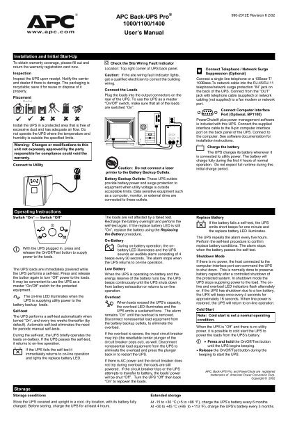
2 Connect to Utility Check the Site Wiring Fault Indicator Location: Top right corner of UPS back panel. Caution: If the site wiring fault indicator lights, get a qualified electrician to correct the building wiring. Connect the Loads Plug the loads into the output connectors on the rear of the UPS. To use the UPS as a master On/Off switch, make sure that all of the loads are switched On . Caution: Do not connect a laser printer to the Battery Backup Outlets. Battery Backup Outlets: These UPS outlets provide battery power and surge protection to equipment when utility voltage is outside acceptable limits. Data sensitive equipment such as a computer, monitor, or external drive are connected to these outlets.
3 Connect Telephone / Network Surge Suppression (Optional) Connect a single line telephone or a 10 Base-T/ 100 Base-Tx network cable into the RJ-45/RJ-11 telephone/network surge protection IN jack on the back of the UPS. Connect from the OUT jack with telephone cable (supplied) or network cabling (not supplied) to a fax modem or network port. Connect Computer Interface Port (Optional, BP1100) PowerChute plus power management software is included with this UPS. Connect the supplied interface cable to the 9-pin computer interface port on the back panel of the UPS. Connect to the computer. See software documentation for installation instructions. Charge the battery The UPS charges its battery whenever it is connected to utility power.
4 The battery will charge fully during the first 4 hours of normal operation. Do not expect full runtime during this initial charge period. Operating Instructions Switch On Switch Off With the UPS plugged in, press and release the On/Off/Test button to supply power to the loads. The UPS loads are immediately powered while the UPS performs a self-test. Press and release the button again to turn Off power to the loads. It may be convenient to use the UPS as a master On/Off switch for the protected equipment. The on-line LED illuminates when the UPS is supplying utility power to the battery backup loads. Self-test The UPS performs a self-test automatically when turned On , and every two weeks thereafter (by default).
5 Automatic self-test eliminates the need for periodic Manual self-tests. During the self-test, the UPS briefly operates the loads on-battery. If the UPS passes the self-test, it returns to on-line operation. If the UPS fails the self-test it immediately returns to on-line operation and lights the replace battery LED. The loads are not affected by a failed test. Recharge the battery overnight and perform the self-test again. If the replace battery LED is still «On , replace the battery using the Replacing the Battery procedure. On-Battery During on-battery operation, the on-battery LED illuminates and the UPS sounds an audible alarm consisting of 4 beeps every 30 seconds. The alarm stops when the UPS returns to on-line operation.
6 Low Battery When the UPS is operating on-battery and the energy reserve of the battery runs low, the UPS beeps continuously until the UPS shuts down from battery exhaustion or returns to on-line operation. Overload When loads exceed the UPS s capacity, the overload LED illuminates and the UPS emits a sustained tone. The alarm remains On until the overload is removed. Disconnect nonessential load equipment from the battery backup outlets, to eliminate the overload. If the overload is severe, the input circuit breaker may trip (the resettable center plunger of the circuit breaker pops out), as well. Disconnect nonessential load equipment from the UPS to eliminate the overload and press the plunger back in to restart the UPS.
7 If there is AC power and the circuit breaker does not trip during overload, the loads are still powered. If the circuit breaker trips or the UPS attempts to transfer to battery, the loads power will be shut Off . Turn the UPS Off then back On to repower the loads. Replace Battery If the battery fails a self-test, the UPS emits short beeps for one minute and the replace battery LED illuminates. The UPS repeats the alarm every five hours. Perform the self-test procedure to confirm replace battery conditions. The alarm stops when the battery passes the self-test. Shutdown Mode If there is no power, the host connected to the computer interface port can command the UPS to shut down.
8 This is normally done to preserve battery capacity after a controlled shutdown of the protected system. In shutdown mode the UPS stops supplying power to the load. The on-line and overload LED indicators flash alternately or, if the UPS has shutdown due to a low battery, the UPS will beep once every 4 seconds for approximately 16 seconds. When line power is restored, the UPS will return to on-line operation. Cold Start Note: Cold start is not a normal operating condition. When the UPS is Off and there is no utility power, it is possible to cold start the UPS to power the loads from the UPS s battery. Press and hold the On/Off/Test button until the UPS begins beeping. Release the On/Off/Test button during the beeping to start the UPS.
9 APC, Back-UPS Pro, and PowerChute are registered trademarks of American Power Conversion Corp. Copyright 2002 StorageStorage conditions Store the UPS covered and upright in a cool, dry location, with its battery fully charged. Before storing, charge the UPS for at least 4 hours. Extended storage At -15 to +30 C (+5 to +86 F), charge the UPS s battery every 6 months At +30 to +45 C (+86 to +113 F), charge the UPS s battery every 3 months. Replacing the Battery This UPS has an easy to replace hot-swappable battery. Battery replacement is a safe procedure, isolated from electrical hazards. You may leave the UPS and loads on for the following procedure.
10 See your dealer or call the number in this Manual for information on replacement battery kits. Note: Once the battery is disconnected, the loads are not protected from power outages. 1. Grasp the top of the front cover and tilt it out and down. 2. Unhook the bottom of the cover from the chassis and lift it upward to expose the battery door. Be careful not to strain the ribbon cable. Do not touch the exposed printed circuit board. 3. Fold the front cover on top of the UPS as shown. 4. Use a flat-blade screwdriver or a coin to remove the two battery door screws and open the door. 5. Grasp the tab and gently pull the battery out of the UPS. 1000 /1100 VA 1400 VA 6. Disconnect the battery leads.