
1
<變數 1> Contents
Contents
Safety Information ………………………………………………………………………………. 2
Specifications ………………………………………………………………………………………3
Rear I/O Panel …………………………………………………………………………………….6
LAN Port LED Status Table ……………………………………………………………………..6
Overview of Components ……………………………………………………………………..7
CPU Socket ……………………………………………………………………………………………8
DIMM Slots ……………………………………………………………………………………………9
PCI_E1~3: PCIe Expansion Slots………………………………………………………………9
JFP1, JFP2: Front Panel Connectors ………………………………………………………10
SATA1~6: SATA 6Gb/s Connectors ………………………………………………………….10
M2_1: M.2 Slot (Key M) ………………………………………………………………………….11
ATX_PWR1, CPU_PWR1: Power Connectors ……………………………………………11
JUSB2~3: USB 2.0 Connectors ………………………………………………………………12
JUSB1: USB 3.1 Gen1 Connector ……………………………………………………………12
CPU_FAN1, SYS_FAN1~2: Fan Connectors ……………………………………………..13
JTPM1: TPM Module Connector……………………………………………………………..14
JCI1: Chassis Intrusion Connector …………………………………………………………14
JAUD1: Front Audio Connector ………………………………………………………………15
JCOM1: Serial Port Connector ……………………………………………………………….15
JLPT1: Parallel Port Connector ……………………………………………………………..15
JLED1: RGB LED connector …………………………………………………………………..16
JBAT1: Clear CMOS (Reset BIOS) Jumper ……………………………………………….16
Onboard LEDs………………………………………………………………………………………17
BIOS Setup ……………………………………………………………………………………….. 18
Entering BIOS Setup……………………………………………………………………………..18
Resetting BIOS …………………………………………………………………………………….19
Updating BIOS ……………………………………………………………………………………..19
Software Description ………………………………………………………………………….20
Installing Windows
®
7/ 8.1/ 10 ……………………………………………………………….20
Installing Drivers ………………………………………………………………………………….20
Installing Utilities …………………………………………………………………………………20
Thank you for purchasing the MSI
®
H270M PRO-VDH/ B250M
PRO-VDH motherboard. This User Guide gives information
about board layout, component overview, BIOS setup and
software installation.
![]()
Thank you for purchasing the MSI® H270M PRO-VDH/ B250M PRO-VDH motherboard. This User Guide gives information about board layout, component overview, BIOS setup and software installation.
|
Contents |
|
|
Safety Information………………………………………………………………………………. |
2 |
|
Specifications……………………………………………………………………………………… |
3 |
|
Rear I/O Panel ……………………………………………………………………………………. |
6 |
|
LAN Port LED Status Table …………………………………………………………………….. |
6 |
|
Overview of Components …………………………………………………………………….. |
7 |
|
CPU Socket…………………………………………………………………………………………… |
8 |
|
DIMM Slots …………………………………………………………………………………………… |
9 |
|
PCI_E1~3: PCIe Expansion Slots……………………………………………………………… |
9 |
|
JFP1, JFP2: Front Panel Connectors……………………………………………………… |
10 |
|
SATA1~6: SATA 6Gb/s Connectors…………………………………………………………. |
10 |
|
M2_1: M.2 Slot (Key M)…………………………………………………………………………. |
11 |
|
ATX_PWR1, CPU_PWR1: Power Connectors…………………………………………… |
11 |
|
JUSB2~3: USB 2.0 Connectors ……………………………………………………………… |
12 |
|
JUSB1: USB 3.1 Gen1 Connector…………………………………………………………… |
12 |
|
CPU_FAN1, SYS_FAN1~2: Fan Connectors …………………………………………….. |
13 |
|
JTPM1: TPM Module Connector…………………………………………………………….. |
14 |
|
JCI1: Chassis Intrusion Connector ………………………………………………………… |
14 |
|
JAUD1: Front Audio Connector ……………………………………………………………… |
15 |
|
JCOM1: Serial Port Connector………………………………………………………………. |
15 |
|
JLPT1: Parallel Port Connector…………………………………………………………….. |
15 |
|
JLED1: RGB LED connector………………………………………………………………….. |
16 |
|
JBAT1: Clear CMOS (Reset BIOS) Jumper………………………………………………. |
16 |
|
Onboard LEDs……………………………………………………………………………………… |
17 |
|
BIOS Setup……………………………………………………………………………………….. |
18 |
|
Entering BIOS Setup…………………………………………………………………………….. |
18 |
|
Resetting BIOS ……………………………………………………………………………………. |
19 |
|
Updating BIOS …………………………………………………………………………………….. |
19 |
|
Software Description…………………………………………………………………………. |
20 |
|
Installing Windows® 7/ 8.1/ 10 ………………………………………………………………. |
20 |
|
Installing Drivers…………………………………………………………………………………. |
20 |
|
Installing Utilities ………………………………………………………………………………… |
20 |
Contents 1
Safety Information
yThe components included in this package are prone to damage from electrostatic discharge (ESD). Please adhere to the following instructions to ensure successful computer assembly.
yEnsure that all components are securely connected. Loose connections may cause the computer to not recognize a component or fail to start.
yHold the motherboard by the edges to avoid touching sensitive components.
yIt is recommended to wear an electrostatic discharge (ESD) wrist strap when handling the motherboard to prevent electrostatic damage. If an ESD wrist strap is not available, discharge yourself of static electricity by touching another metal object before handling the motherboard.
yStore the motherboard in an electrostatic shielding container or on an anti-static pad whenever the motherboard is not installed.
yBefore turning on the computer, ensure that there are no loose screws or metal components on the motherboard or anywhere within the computer case.
yDo not boot the computer before installation is completed. This could cause permanent damage to the components as well as injury to the user.
yIf you need help during any installation step, please consult a certified computer technician.
yAlways turn off the power supply and unplug the power cord from the power outlet before installing or removing any computer component.
yKeep this user guide for future reference.
yKeep this motherboard away from humidity.
yMake sure that your electrical outlet provides the same voltage as is indicated on the PSU, before connecting the PSU to the electrical outlet.
yPlace the power cord such a way that people can not step on it. Do not place anything over the power cord.
yAll cautions and warnings on the motherboard should be noted.
yIf any of the following situations arises, get the motherboard checked by service personnel:
Liquid has penetrated into the computer.
The motherboard has been exposed to moisture.
The motherboard does not work well or you can not get it work according to user guide.
The motherboard has been dropped and damaged.
The motherboard has obvious sign of breakage.
yDo not leave this motherboard in an environment above 60°C (140°F), it may damage the motherboard.
2 Safety Information

Specifications
|
CPU |
Supports 6th/ 7th Gen Intel® Core™ i3/i5/i7 processors, and |
|
|
Intel® Pentium® and Celeron® processors for Socket LGA1151 |
||
|
Chipset |
Intel® H270/ B250 Chipset |
|
|
y 4x DDR4 memory slots, support up to 64GB |
||
|
7th Gen processors support DDR4 2400/ 2133 MHz* |
||
|
6th Gen processors support DDR4 2133 MHz* |
||
|
y Dual channel memory architecture |
||
|
Memory |
y Supports Intel® Extreme Memory Profile (XMP)** |
|
|
* Please refer www.msi.com for more information on |
||
|
compatible memory. |
||
|
** DDR4 memory modules can only run at maximum of 2400 |
||
|
MHz for 7th Gen processors and 2133 MHz for 6th Gen |
||
|
processors on XMP mode. |
||
|
Expansion Slots |
y 1x PCIe 3.0 x16 slot (supports x16 mode) |
|
|
y 2x PCIe 3.0 x1 slots |
||
|
y 1x HDMI™ port, supports a maximum resolution of |
||
|
4096×2160@24Hz, 2560×1600@60Hz |
||
|
Onboard Graphics |
y 1x DVI-D port, supports a maximum resolution of |
|
|
1920×1200@60Hz |
||
|
y 1x VGA port, supports a maximum resolution of |
||
|
2048×1536@50Hz, 2048×1280@60Hz, 1920×1200@60Hz |
||
|
Intel® H270/ B250 Chipset |
||
|
y 6x SATA 6Gb/s ports |
||
|
y 1x M.2 slot (Key M) |
||
|
Storage |
Supports up to PCIe 3.0 x4 and SATA 6Gb/s |
|
|
Supports 2242/ 2260 /2280 storage devices |
||
|
Intel® Optane™ Memory Ready |
||
|
y H270 supports RAID 0, RAID1, RAID 5 and RAID 10 for SATA |
||
|
storage devices |
||
|
Intel® H270/ B250 Chipset |
||
|
y 6x USB 3.1 Gen1 (SuperSpeed USB) ports (3 Type-A & 1 |
||
|
USB |
Type-C ports on the back panel, 2 ports available through the |
|
|
internal USB connector) |
||
|
y 6x USB 2.0 (High-speed USB) ports (2 ports on the back |
||
|
panel, 4 ports available through the internal USB connector) |
||
|
Audio |
y Realtek® ALC887 Codec |
|
|
y 7.1-Channel High Definition Audio |
||
|
LAN |
1x Realtek® 8111H Gigabit LAN controller |
|
|
Continued on next page |
Specifications 3

|
Continued from previous page |
||
|
y 1x PS/2 keyboard port |
||
|
y 1x PS/2 mouse port |
||
|
y 1x HDMI™ port |
||
|
y 1x VGA port |
||
|
Back Panel |
y 1x DVI-D port |
|
|
Connectors |
y 1x LAN (RJ45) port |
|
|
y 2x USB 2.0 Type-A ports |
||
|
y 3x USB 3.1 Gen1 Type-A ports |
||
|
y 1x USB 3.1 Gen1 Type-C port |
||
|
y 3x audio jacks |
||
|
y 1x 24-pin ATX main power connector |
||
|
y 1x 8-pin ATX 12V power connector |
||
|
y 6x SATA 6Gb/s connectors |
||
|
y 2x USB 2.0 connectors (supports additional 4 USB 2.0 ports) |
||
|
y 1x USB 3.1 Gen1 connector (supports additional 2 USB 3.1 |
||
|
Gen1 ports) |
||
|
y 1x 4-pin CPU fan connector |
||
|
Internal |
y 2x 4-pin system fan connectors |
|
|
y 1x Front panel audio connector |
||
|
Connectors |
||
|
y 2x Front panel connectors |
||
|
y 1x TPM module connector |
||
|
y 1x Chassis Intrusion connector |
||
|
y 1x Serial port connector |
||
|
y 1x Parallel port connector |
||
|
y 1x RGB LED connecotr |
||
|
y 1x TBT connector |
||
|
y 1x Clear CMOS jumper |
||
|
I/O Controller |
NUVOTON NCT6795 Controller Chip |
|
|
Hardware |
y CPU/System temperature detection |
|
|
y CPU/System fan speed detection |
||
|
Monitor |
||
|
y CPU/System fan speed control |
||
|
Form Factor |
y m-ATX Form Factor |
|
|
y 9.6 in. x 9.0 in. (24.4 cm x 22.8 cm) |
||
|
y 1x 64 Mb flash |
||
|
BIOS Features |
y UEFI AMI BIOS |
|
|
y ACPI 5.0, PnP 1.0a, SM BIOS 2.8 |
||
|
y Multi-language |
||
|
Continued on next page |
4 Specifications
Continued from previous page
|
y Drivers |
||
|
y COMMAND CENTER |
||
|
y LIVE UPDATE 6 |
||
|
y FAST BOOT |
||
|
y SUPER CHARGER |
||
|
y MYSTIC LIGHT |
||
|
Software |
y RAMDISK |
|
|
y X-BOOST |
||
|
y MSI SMART TOOL |
||
|
y NETWORK GENIE |
||
|
y Intel® Extreme Tuning Utility |
||
|
y Norton™ Security |
||
|
y Google Chrome™,Google Toolbar, Google Drive |
||
|
y CPU-Z MSI GAMING |
Specifications 5
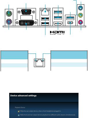
|
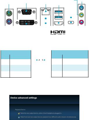
Rear I/O Panel |
USB 3.1 |
||||
|
Line-out |
Line-in |
||||
|
PS/2 Mouse |
VGA |
LAN |
Gen1 |
||
|
Type-A |
|||||
|
USB 3.1 |
|||||
|
Gen1 |
|||||
|
Type-A |
|||||
|
PS/2 Keyboard |
DVI-D |
Mic in |
|||
|
USB 2.0 |
USB 3.1 Gen1 |
||||
|
Type-C |
LAN Port LED Status Table
Link/ Activity LED
|
Status |
Description |
|
Off |
No link |
|
Yellow |
Linked |
|
Blinking |
Data activity |
Speed LED
|
Status |
Description |
|
Off |
10 Mbps connection |
|
Green |
100 Mbps connection |
|
Orange |
1 Gbps connection |
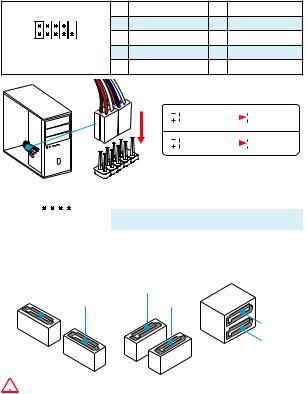
Audio 7.1-channel Configuration
To configure 7.1-channel audio, you have to connect front audio I/O module to JAUD1 connector and follow the below steps.
1.Click on the Realtek HD Audio Manager > Advanced Settings to open the dialog below.
2.Select Mute the rear output device, when a front headphone plugged in.
3.Plug your speakers to audio jacks on rear and front I/O panel. When you plug into a device at an audio jack, a dialogue window will pop up asking you which device is current connected.
6 Rear I/O Panel

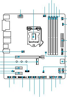
Overview of Components
SYS_FAN1
PCI_E1
M2_1
JTPM1
PCI_E2
JLED1
PCI_E3
|
DIMMA2 |
|||
|
DIMMA1 |
DIMMB1 |
||
|
CPU_FAN1 |
DIMMB2 |
||
|
CPU_PWR1 CPU Socket |
DIMM LEDs |
||
|
SYS_FAN2 |
|||
|
EZ Debug LED |
|||
|
ATX_PWR1 |
|||
|
JUSB1 |
|||
|
JBAT1 |
|||
|
SATA▼1▲2 |
|||
|
JCI1 |
|||
|
SATA3 |
|||
|
SATA4 |
|||
|
JCOM1 |
JFP1 |
||
|
JAUD1 |
JLPT1 |
JFP2 |
|
|
JUSB3 |
SATA5 |
||
|
JUSB2 |
SATA6 |
JTBT1*
* JTBT1 is used to connect a specific card.
Overview of Components 7
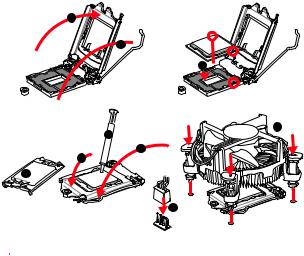
CPU Socket
Please install the CPU into the CPU socket as shown below.
2
1
3


 8 7
8 7 


5
 4 6
4 6


9
 Important
yAlways unplug the power cord from the power outlet before installing or removing the CPU.
yPlease retain the CPU protective cap after installing the processor. MSI will deal with Return Merchandise Authorization (RMA) requests if only the motherboard comes with the protective cap on the CPU socket.
yWhen installing a CPU, always remember to install a CPU heatsink. A CPU heatsink is necessary to prevent overheating and maintain system stability.
yConfirm that the CPU heatsink has formed a tight seal with the CPU before booting your system.
yOverheating can seriously damage the CPU and motherboard. Always make sure the cooling fans work properly to protect the CPU from overheating. Be sure to apply an even layer of thermal paste (or thermal tape) between the CPU and the heatsink to enhance heat dissipation.
yWhenever the CPU is not installed, always protect the CPU socket pins by covering the socket with the plastic cap.
yIf you purchased a separate CPU and heatsink/ cooler, Please refer to the documentation in the heatsink/ cooler package for more details about installation.
8 Rear I/O Panel
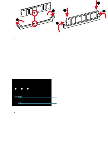
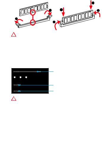
DIMM Slots
Please install the memory module into the DIMM slot as shown below.
1
3
 Important
yTo boot up the system successfully, always insert the memory module into DIMMA2 first.
yDue to chipset resource usage, the available capacity of memory will be a little less than the amount of installed.
yPlease note that the maximum capacity of addressable memory is 4GB or less for 32-bit Windows OS due to the memory address limitation. Therefore, we
recommended that you to install 64-bit Windows OS if you want to install more than 4GB memory on the motherboard.
PCI_E1~3: PCIe Expansion Slots


 PCI_E1: PCIe 3.0 x16 slot
PCI_E2: PCIe 3.0 x1 slot
PCI_E3: PCIe 3.0 x1 slot
 Important
When adding or removing expansion cards, always turn off the power supply and unplug the power supply power cable from the power outlet. Read the expansion card’s documentation to check for any necessary additional hardware or software changes.
Rear I/O Panel 9
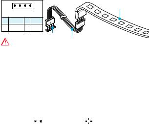
JFP1, JFP2: Front Panel Connectors
These connectors connect to the switches and LEDs on the front panel.
|
2 |
10 |
1 |
HDD LED + |
2 |
Power LED + |
|
|
3 |
HDD LED — |
4 |
Power LED — |
|||
|
1 |
9 |
5 |
Reset Switch |
6 |
Power Switch |
|
|
7 |
Reset Switch |
8 |
Power Switch |
|||
|
JFP1 |
||||||
|
9 |
Reserved |
10 |
No Pin |
HDD
 LEDSWRESET
JFP1
|
HDD LED |
HDD LED — |
||||||
|
HDD LED + |
|||||||
|
POWER LED — |
|||||||
|
POWER LED |
POWER LED + |
||||||
|
1 |
1 |
Speaker — |
2 |
Buzzer + |
|||||
|
JFP2 |
3 |
Buzzer — |
4 |
Speaker + |
|||||
SATA1~6: SATA 6Gb/s Connectors
These connectors are SATA 6Gb/s interface ports. Each connector can connect to one SATA device.
|
SATA6 |
SATA4 |
|
SATA5 |
SATA3 |
|
SATA2 |
|
|
SATA1 |
 Important
yPlease do not fold the SATA cable at a 90-degree angle. Data loss may result during transmission otherwise.
ySATA cables have identical plugs on either sides of the cable. However, it is recommended that the flat connector be connected to the motherboard for space saving purposes.
10 Rear I/O Panel
![]()
M2_1: M.2 Slot (Key M)
Please install the M.2 solid-state drive (SSD) into the M.2 slot as shown below.
|
4 |
|||
|
1 |
3 |
5 |
|
|
30° |
|||
|
2 |
 Important
Intel® RST only supports PCIe M.2 SSD with UEFI ROM, does not support Legacy ROM.
ATX_PWR1, CPU_PWR1: Power Connectors
These connectors allow you to connect an ATX power supply.
|
1 |
+3.3V |
13 |
+3.3V |
|||||
|
2 |
+3.3V |
14 |
-12V |
|||||
|
12 |
24 |
3 |
Ground |
15 |
Ground |
|||
|
4 |
+5V |
16 |
PS-ON# |
|||||
|
5 |
Ground |
17 |
Ground |
|||||
|
ATX_PWR1 |
6 |
+5V |
18 |
Ground |
||||
|
7 |
Ground |
19 |
Ground |
|||||
|
8 |
PWR OK |
20 |
Res |
|||||
|
1 |
13 |
9 |
5VSB |
21 |
+5V |
|||
|
10 |
+12V |
22 |
+5V |
|||||
|
11 |
+12V |
23 |
+5V |
|||||
|
12 |
+3.3V |
24 |
Ground |
|
8 |
5 |
1 |
Ground |
5 |
+12V |
|
|
CPU_PWR1 |
2 |
Ground |
6 |
+12V |
||
|
3 |
Ground |
7 |
+12V |
|||
|
4 |
1 |
|||||
|
4 |
Ground |
8 |
+12V |
|||
 Important
Make sure that all the power cables are securely connected to a proper ATX power supply to ensure stable operation of the motherboard.
Rear I/O Panel 11
JUSB2~3: USB 2.0 Connectors
These connectors allow you to connect USB 2.0 ports on the front panel.
|
1 |
VCC |
2 |
VCC |
|||||||
|
2 |
10 |
3 |
USB0- |
4 |
USB1- |
|||||
|
5 |
USB0+ |
6 |
USB1+ |
|||||||
|
1 |
9 |
7 |
Ground |
8 |
Ground |
|||||
|
9 |
No Pin |
10 |
NC |
 Important
yNote that the VCC and Ground pins must be connected correctly to avoid possible damage.
yIn order to recharge your iPad,iPhone and iPod through USB ports, please install MSI® SUPER CHARGER utility.
JUSB1: USB 3.1 Gen1 Connector
This connector allows you to connect USB 3.1 Gen1 ports on the front panel.
|
1 |
Power |
11 |
USB2.0+ |
|||
|
2 |
USB3_RX_DN |
12 |
USB2.0- |
|||
|
10 |
11 |
3 |
USB3_RX_DP |
13 |
Ground |
|
|
4 |
Ground |
14 |
USB3_TX_C_DP |
|||
|
5 |
USB3_TX_C_DN |
15 |
USB3_TX_C_DN |
|||
|
6 |
USB3_TX_C_DP |
16 |
Ground |
|||
|
7 |
Ground |
17 |
USB3_RX_DP |
|||
|
1 |
20 |
8 |
USB2.0- |
18 |
USB3_RX_DN |
|
|
9 |
USB2.0+ |
19 |
Power |
|||
|
10 |
NC |
20 |
No Pin |
 Important
Note that the Power and Ground pins must be connected correctly to avoid possible damage.
12 Rear I/O Panel
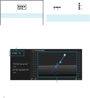
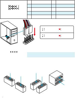
CPU_FAN1, SYS_FAN1~2: Fan Connectors
Fan connectors can be classified as PWM (Pulse Width Modulation) Mode and DC Mode. PWM Mode fan connectors provide constant 12V output and adjust fan speed with speed control signal. DC Mode fan connectors control fan speed by changing voltage. Therefore, when you plug a 3-pin (Non-PWM) fan to a PWM Mode fan connector, the fan speed will be always maintained at 100%, and that could be noisy.
PWM Mode fan connector
1
CPU_FAN1
|
1 |
Ground |
2 |
+12V |
|
|
3 |
Sense |
4 |
Speed Control |
|
|
Signal |
||||
DC Mode fan connector
|
1 |
1 |
|||||||||
|
SYS_FAN1 |
||||||||||
|
SYS_FAN2 |
||||||||||
|
1 |
Ground |
2 |
Voltage |
|||||||
|
Control |
||||||||||
|
3 |
Sense |
4 |
NC |
Switching fan mode and adjusting fan speed
You can switch between PWM mode and DC mode and adjust fan speed in BIOS > HARDWARE MONITOR.
Select PWM mode or DC mode
There are gradient points of the fan speed that allow you to adjust fan speed in relation to CPU temperature.
 Important
Make sure fans are working properly after switching the PWM/ DC mode.
Rear I/O Panel 13
JTPM1: TPM Module Connector
This connector is for TPM (Trusted Platform Module). Please refer to the TPM security platform manual for more details and usages.
|
1 |
LPC Clock |
2 |
3V Standby power |
|||||||||
|
3 |
LPC Reset |
4 |
3.3V Power |
|||||||||
|
2 |
14 |
5 |
LPC address & data pin0 |
6 |
Serial IRQ |
|||||||
|
7 |
LPC address & data pin1 |
8 |
5V Power |
|||||||||
|
1 |
13 |
9 |
LPC address & data pin2 |
10 |
No Pin |
|||||||
|
11 |
LPC address & data pin3 |
12 |
Ground |
|||||||||
|
13 |
LPC Frame |
14 |
Ground |
JCI1: Chassis Intrusion Connector
This connector allows you to connect the chassis intrusion switch cable.
|
Normal |
Trigger the chassis |
|||
|
(default) |
intrusion event |
Using chassis intrusion detector
1.Connect the JCI1 connector to the chassis intrusion switch/ sensor on the chassis.
2.Close the chassis cover.
3.Go to BIOS > Security > Chassis Intrusion Configuration.
4.Set Chassis Intrusion to Enabled.
5.Press F10 to save and exit and then press the Enter key to select Yes.
6.Once the chassis cover is opened again, a warning message will be displayed on screen when the computer is turned on.
Resetting the chassis intrusion warning
1.Go to BIOS > Security > Chassis Intrusion Configuration.
2.Set Chassis Intrusion to Reset.
3.Press F10 to save and exit and then press the Enter key to select Yes.
14 Rear I/O Panel
JAUD1: Front Audio Connector
This connector allow you to connect audio jacks on the front panel.
|
1 |
MIC L |
2 |
Ground |
|||||||
|
2 |
10 |
3 |
MIC R |
4 |
NC |
|||||
|
5 |
Head Phone R |
6 |
MIC Detection |
|||||||
|
1 |
9 |
7 |
SENSE_SEND |
8 |
No Pin |
|||||
|
9 |
Head Phone L |
10 |
Head Phone Detection |
JCOM1: Serial Port Connector
This connector allows you to connect the optional serial port with bracket.
|
1 |
DCD |
2 |
SIN |
|||||||
|
2 |
10 |
3 |
SOUT |
4 |
DTR |
|||||
|
5 |
Ground |
6 |
DSR |
|||||||
|
1 |
9 |
7 |
RTS |
8 |
CTS |
|||||
|
9 |
RI |
10 |
No Pin |
JLPT1: Parallel Port Connector
This connector allows you to connect the optional parallel port with bracket.
|
2 |
26 |
|||||||||||||||||
|
1 |
25 |
|||||||||||||||||
|
1 |
RSTB# |
2 |
AFD# |
3 |
PRND0 |
|||||||||||||
|
4 |
ERR# |
5 |
PRND1 |
6 |
PINIT# |
|||||||||||||
|
7 |
PRND2 |
8 |
LPT_SLIN# |
9 |
PRND3 |
|||||||||||||
|
10 |
Ground |
11 |
PRND4 |
12 |
Ground |
|||||||||||||
|
13 |
PRND5 |
14 |
Ground |
15 |
PRND6 |
|||||||||||||
|
16 |
Ground |
17 |
PRND7 |
18 |
Ground |
|||||||||||||
|
19 |
ACK# |
20 |
Ground |
21 |
BUSY |
|||||||||||||
|
22 |
Ground |
23 |
PE |
24 |
Ground |
|||||||||||||
|
25 |
SLCT |
26 |
No Pin |
Rear I/O Panel 15
JLED1: RGB LED connector
These connectors allow you to connect the 5050 RGB LED strips.
5050 LED strip
|
1 |
||||
|
1 |
+12V |
2 |
G |
|
|
3 |
R |
4 |
B |
|
|
1 JLED1 |
Extension cable |
|||
|
Important |
yThis connector supports 5050 RGB multi-color LED strips (12V/G/R/B) with the maximum power rating of 3A (12V). Please keeping the LED strip shorter than 2 meters to prevent dimming.
yAlways turn off the power supply and unplug the power cord from the power outlet before installing or removing the RGB LED strip.
yPlease use the LED Effect of GAMING APP to adjust, calibrate and control the LED light, refer to the Software section for details.
JBAT1: Clear CMOS (Reset BIOS) Jumper
There is CMOS memory onboard that is external powered from a battery located on the motherboard to save system configuration data. If you want to clear the system configuration, set the jumpers to clear the CMOS memory.
|
Keep Data |
Clear CMOS/ Reset |
|||
|
(default) |
BIOS |
Resetting BIOS to default values
1.Power off the computer and unplug the power cord
2.Use a jumper cap to short JBAT1 for about 5-10 seconds.
3.Remove the jumper cap from JBAT1.
4.Plug the power cord and power on the computer.
16 Rear I/O Panel
Onboard LEDs
DIMM LEDs — indicate the memory modules are installed.
PCIe x16 slot LED — indicates the PCIe x16 slots status. [Red] — x16 mode. [White] — X8, X4, X1 mode.
EZ Debug LED
These LEDs indicate the status of the motherboard.

 CPU — indicates CPU is not detected or fail.

 DRAM — indicates DRAM is not detected or fail.

 VGA — indicates GPU is not detected or fail.

 BOOT — indicates booting device is not detected or fail.
Rear I/O Panel 17

BIOS Setup
The default settings offer the optimal performance for system stability in normal conditions. You should always keep the default settings to avoid possible system damage or failure booting unless you are familiar with BIOS.
 Important
yBIOS items are continuous update for better system performance. Therefore, the description may be slightly different from the latest BIOS and should be held for reference only. You could also refer to the HELP information panel for BIOS item description.
yThe pictures in this chapter are for reference only and may vary from the product you purchased.
Entering BIOS Setup
Please refer the following methods to enter BIOS setup.
yPress Delete key, when the Press DEL key to enter Setup Menu, F11 to enter Boot Menu message appears on the screen during the boot process.
yUse MSI FAST BOOT application. Click on GO2BIOS button and choose OK. The system will reboot and enter BIOS setup directly.
Click on GO2BIOS
Function key
|
Key |
Function |
Key |
Function |
|
|
F1 |
General Help |
F2 |
Add/ Remove a favorite item |
|
|
F3 |
Enter Favorites menu |
F4 |
Enter CPU Specifications menu |
|
|
F5 |
Enter Memory-Z menu |
F6 |
Load optimized defaults |
|
|
F7 |
Switch between Advanced mode |
F8 |
Load Overclocking Profile |
|
|
and EZ mode |
||||
|
F9 |
Save Overclocking Profile |
F10 |
Save Change and Reset* |
|
F12 Take a screenshot and save it to USB flash drive (FAT/ FAT32 format only).
* When you press F10, a confirmation window which provides the modification information appears. Select between Yes or No to confirm your choice.
18 BIOS Setup

Resetting BIOS
You might need to restore the default BIOS setting to solve certain problems. There are several ways to reset BIOS:
yGo to BIOS and press F6 to load optimized defaults.
yShort the Clear CMOS jumper on the motherboard.
 Important
Please refer to the Clear CMOS jumper section for resetting BIOS.
Updating BIOS
Updating BIOS with M-FLASH
Before updating:
Please download the latest BIOS file that matches your motherboard model from MSI website. And then save the BIOS file into the USB flash drive.
Updating BIOS:
1.Insert the USB flash drive that contains the update file into the computer.
2.Reboot the system, and then press Del key to enter the BIOS Setup during POST.
3.Go to BIOS > M-FLASH > Select one file to update BIOS and ME, select a BIOS file to perform the BIOS update process.
4.After the flashing process is 100% complete, the system will reboot.
Updating the BIOS with Live Update 6
Before updating:
Make sure the LAN driver is already installed and the internet connection is set properly.
Updating BIOS:
1.Install and launch MSI LIVE UPDATE 6.
2.Select Manual scan.
3.Check MB BIOS box and click on Scan button.
|
4. Select the MB BIOS and click on |
icon to download and install the latest BIOS |
|
file. |
5.Click Next and choose In Windows mode. And then click Next and Start to start updating BIOS.
6.After the flashing process is 100% completed, the system will restart automatically.
BIOS Setup 19
Software Description
Installing Windows® 7/ 8.1/ 10
1.Power on the computer.
2.Insert the Windows® 7/ 8.1/ 10 disc into your optical drive.
Note: Due to chipset limitation, during the Windows® 7 installation process, USB optical drives and USB pen drives are not supported. You can use MSI Smart Tool to install Windows® 7.
3.Press the Restart button on the computer case.
4.For windows 8.1/ 10, skip this step. For Windows 7, access the BIOS menu
Advanced > Windows OS Configuration > Windows 7 Installation and set the item to enabled, save changes and restart.
Note: It is suggested to plug in your USB Keyboard/USB Mouse to the leftmost USB port when installing Windows 7.
5.Press F11 key during the computer POST (Power-On Self Test) to get into Boot Menu.
6.Select your optical drive from the Boot Menu.
7.Press any key when screen shows Press any key to boot from CD or DVD…
message.
8.Follow the instructions on the screen to install Windows® 7/ 8.1/ 10.
Installing Drivers
1.Start up your computer in Windows® 7/ 8.1/ 10.
2.Insert MSI® Driver Disc into your optical drive.
3.The installer will automatically appear and it will find and list all necessary drivers.
4.Click Install button.
5.The software installation will then be in progress, after it has finished it will prompt you to restart.
6.Click OK button to finish.
7.Restart your computer.
Installing Utilities
Before you install utilities, you must complete drivers installation.
1.Insert MSI® Driver Disc into your optical drive.
2.The installer will automatically appear.
3.Click Utilities tab.
4.Select the utilities you want to install.
5.Click Install button.
6.The utilities installation will then be in progress, after it has finished it will prompt you to restart.
7.Click OK button to finish.
8.Restart your computer.
20 Software Description
![]()
MSI® H270M PRO-VDH/ B250M PRO-VDH. ,, BIOS .
|
…………………………………………………………………………………………….. |
2 |
|||
|
……………………………………………………………………………………………………. |
3 |
|||
|
I/O ……………………………………………………………………………………….. |
6 |
|||
|
LAN LED ……………………………………………………………………….. |
6 |
|||
|
……………………………………………………………………………………………………. |
7 |
|||
|
CPU ………………………………………………………………………………………………. |
8 |
|||
|
DIMM …………………………………………………………………………………………….. |
9 |
|||
|
PCI_E1~3: PCIe ……………………………………………………………………….. |
9 |
|||
|
JFP1, JFP2: …………………………………………………………………. |
10 |
|||
|
SATA1~6: SATA 6Gb/s ………………………………………………………………… |
10 |
|||
|
M2_1: M.2 |
(Key M) ………………………………………………………………………… |
11 |
||
|
ATX_PWR1, CPU_PWR1: ……………………………………………………… |
11 |
|||
|
JUSB2~3: USB 2.0 ……………………………………………………………………… |
12 |
|||
|
JUSB1: USB 3.1 Gen1 …………………………………………………………………. |
12 |
|||
|
CPU_FAN1, SYS_FAN1~2: ……………………………………………………….. |
13 |
|||
|
JTPM1: TPM ……………………………………………………………………….. |
14 |
|||
|
JCI1: |
…………………………………………………………………………… |
14 |
||
|
JAUD1: |
…………………………………………………………………….. |
15 |
||
|
JCOM1: |
……………………………………………………………………. |
15 |
||
|
JLPT1: ……………………………………………………………………… |
15 |
|||
|
JLED1: RGB LED ……………………………………………………………………….. |
16 |
|||
|
JBAT1: CMOS (Reset BIOS) ………………………………………………….. |
16 |
|||
|
LED………………………………………………………………………………………….. |
17 |
|||
|
BIOS ………………………………………………………………………………………….. |
18 |
|||
|
BIOS |
……………………………………………………………………………………………. |
18 |
||
|
BIOS |
……………………………………………………………………………………………. |
19 |
||
|
BIOS |
……………………………………………………………………………………… |
19 |
||
|
…………………………………………………………………………………..® |
20 |
|||
|
Windows |
7/ 8.1/ 10 ………………………………………………………………… |
20 |
||
|
…………………………………………………………………………………. |
20 |
|||
|
…………………………………………………………………………………. |
20 |
1
y (ESD).
y . ,.
y .
y ESD. ESD ,.
y .
y .
y . ,.
y .
y .
y . y .
y PSU PSU.
y . . y .
y , ..
.
..
.
y 60°C (140°F) . .
2

|
® |
® |
|||||||||||||||
|
6/ 7 |
Gen Intel® Core™ i3/i5/i7 |
LGA1151 |
||||||||||||||
|
CPU |
Intel |
Pentium |
Celeron |
® |
. |
|||||||||||
|
Intel® H270/ B250 |
||||||||||||||||
|
y DDR4 4 , 64GB |
* |
|||||||||||||||
|
7 DDR4 2400/ 2133 MHz |
||||||||||||||||
|
6 DDR4 2133 MHz * |
||||||||||||||||
|
y |
||||||||||||||||
|
y Intel® Extreme Memory Profile (XMP) ** |
||||||||||||||||
|
* |
WWW.MSI. |
|||||||||||||||
|
COM . |
||||||||||||||||
|
** XMP 7 , DDR4 |
||||||||||||||||
|
2400 MHz |
. 6 , |
|||||||||||||||
|
DDR4 2133 MHz . |
||||||||||||||||
|
y PCIe 3.0 x16 1 (x16 ) |
||||||||||||||||
|
y PCIe 3.0 x1 |
2 |
|||||||||||||||
|
y HDMI™ |
1 , 4096×2160@24Hz, 2560×1600@60Hz |
|||||||||||||||
|
y DVI-D |
1 , 1920×1200@60Hz |
|||||||||||||||
|
y VGA 1 , 2048×1536@50Hz, 2048×1280@60Hz, |
||||||||||||||||
|
1920×1200@60Hz |
||||||||||||||||
|
Intel® H270/ B250 |
||||||||||||||||
|
y SATA 6Gb/s |
6 |
|||||||||||||||
|
y M.2 1 (Key M) |
||||||||||||||||
|
2242/ 2260 /2280 |
||||||||||||||||
|
PCIe 3.0 x4 and SATA 6Gb/s |
||||||||||||||||
|
Intel® Optane™ Technology Ready |
(SATA |
|||||||||||||||
|
y H270 RAID 0, RAID1, RAID 5 |
RAID 10 |
|||||||||||||||
|
) |
||||||||||||||||
|
Intel® H270/ B250 |
||||||||||||||||
|
y USB 3.1 Gen1 (SuperSpeed USB) 6 ( |
||||||||||||||||
|
USB |
Type-A 3 & Type-C 1 , USB 2 |
|||||||||||||||
|
) |
||||||||||||||||
|
y USB 2.0 (High-speed USB) 6 ( 2 , |
||||||||||||||||
|
USB 4 ) |
||||||||||||||||
|
y 7.1- HD |
||||||||||||||||
|
y Realtek® ALC887 |
||||||||||||||||
|
LAN |
Realtek® 8111H Gigabit LAN 1 |
|||||||||||||||
3

|
y PS/2 1 |
||||
|
y PS/2 1 |
||||
|
y HDMI™ 1 |
||||
|
y VGA 1 |
||||
|
y DVI-D 1 |
||||
|
y LAN (RJ45) 1 |
||||
|
y USB 2.0 Type-A 2 |
||||
|
y USB 3.1 Gen1 Type-A |
3 |
|||
|
y USB 3.1 Gen1 Type-C |
1 |
|||
|
y 3 |
||||
|
y 24 ATX 1 |
||||
|
y 8 ATX 12V |
1 |
|||
|
y SATA 6Gb/s |
6 |
|||
|
y USB 2.0 2 ( USB 2.0 4 ) |
||||
|
y USB 3.1 Gen1 1 |
( USB 3.1 Gen1 2 ) |
|||
|
y 4- CPU 1 |
||||
|
y 4- 2 |
||||
|
y 1 |
||||
|
y 2 |
||||
|
y TPM 1 |
||||
|
y 1 |
||||
|
y |
1 |
|||
|
y |
1 |
|||
|
y RGB LED 1 |
||||
|
y TBT 1 |
||||
|
y CMOS 1 |
||||
|
I/O |
NUVOTON NCT6795 |
yCPU/y CPU/
yCPU/
|
y m-ATX |
|
|
y 9.6 in. x 9.0 in. (24.4 cm x 22.8 cm) |
|
|
BIOS |
y 64 Mb 1 |
|
y UEFI AMI BIOS |
|
|
y ACPI 5.0, PnP 1.0a, SM BIOS 2.8 |
|
|
y |
|
4
|
y |
|
|
y COMMAND CENTER |
|
|
y LIVE UPDATE 6 |
|
|
y FAST BOOT |
|
|
y SUPER CHARGER |
|
|
y MYSTIC LIGHT |
|
|
y X-BOOST |
|
|
y RAMDISK |
|
|
y MSI SMART TOOL |
|
|
y NETWORK GENIE |
|
|
y Intel® |
|
|
y Norton™ |
|
|
y Google Chrome™,Google Toolbar, Google Drive |
|
|
y CPU-Z MSI GAMING |
5
|
I/O |
USB 3.1 |
||||
|
PS/2 |
VGA |
LAN |
Gen1 |
||
|
Type-A |
USB 3.1 |
||||
|
Gen1 |
|||||
|
Type-A |
|
PS/2 |
DVI |
-D |
||||||||||||||||||||||||||||||||
|
USB 2.0 |
USB 3.1 Gen1 |
|||||||||||||||||||||||||||||||||
|
LAN LED |
Type-C |
|||||||||||||||||||||||||||||||||
|
/ LED |
LED |
|||||||||||||||||||||||||||||||||
|
LAN |
10 Mbps |
|||||||||||||||||||||||||||||||||
|
. |
. |
|||||||||||||||||||||||||||||||||
|
LAN |
100 Mbps |
|||||||||||||||||||||||||||||||||
|
. |
. |
|||||||||||||||||||||||||||||||||
|
LAN |
1 Gbps |
|||||||||||||||||||||||||||||||||
|
. |
. |
7.1
7.1 I/O JAUD1 ..
1.Realtek HD Audio Manager > Advanced Settings( ).
2.[Mute the rear output device, when a front headphone plugged in]() .
3.I/O ..
6 I/O
SYS_FAN1
PCI_E1
M2_1
JTPM1
PCI_E2
JLED1
PCI_E3
|
DIMMA2 |
|||
|
DIMMA1 |
DIMMB1 |
||
|
CPU_PWR1 CPU |
CPU_FAN1 |
DIMMB2 |
|
|
DIMM LEDs |
|||
|
SYS_FAN2 |
|||
|
EZ Debug LED |
|||
|
ATX_PWR1 |
|||
|
JUSB1 |
|||
|
JBAT1 |
|||
|
SATA▼1▲2 |
|||
|
JCI1 |
|||
|
SATA3 |
|||
|
SATA4 |
|||
|
JCOM1 |
JFP1 |
||
|
JAUD1 |
JLPT1 |
JFP2 |
|
|
JUSB3 |
SATA5 |
||
|
JUSB2 |
SATA6 |
JTBT1*
* JTBT1 .
7

CPU
CPU CPU .
2
1
3


 8 7
8 7 


5
 4 6
4 6


9

yCPU .
y, CPU . CPUMSI (RMA) .
yCPU , CPU . CPU.
yCPU .
yCPU CPU. CPU( ) .
yCPU , CPU.
yCPU / , /.
8 I/O
DIMM
DIMM .
1
3

y DIMMA2 . y .
y 4GB 32- (Windows OS). 4GB 64Windows OS .
PCI_E1~3: PCIe
PCI_E1: PCIe 3.0 x16
PCI_E2: PCIe 3.0 x1
PCI_E3: PCIe 3.0 x1

..
I/O 9
JFP1, JFP2:
LED .
|
2 |
10 |
1 |
HDD LED + |
2 |
Power LED + |
|
|
3 |
HDD LED — |
4 |
Power LED — |
|||
|
1 |
9 |
5 |
Reset Switch |
6 |
Power Switch |
|
|
7 |
Reset Switch |
8 |
Power Switch |
|||
|
JFP1 |
||||||
|
9 |
Reserved |
10 |
No Pin |
HDD
 LEDSWRESET
JFP1
|
HDD LED |
HDD LED — |
||||||
|
HDD LED + |
|||||||
|
POWER LED — |
|||||||
|
POWER LED |
POWER LED + |
||||||
|
1 |
1 |
Speaker — |
2 |
Buzzer + |
|||||
|
JFP2 |
3 |
Buzzer — |
4 |
Speaker + |
|||||
SATA1~6: SATA 6Gb/s
SATA 6Gb/s . SATA.
SATA2
SATA1

ySATA 90 . , .
ySATA .
10 I/O
![]()
M2_1: M.2 (Key M)
M.2 M.2 solid-state drive (SSD) .
|
4 |
|||
|
1 |
3 |
5 |
|
|
30° |
|||
|
2 |

Intel® RST UEFI ROM PCIe M.2 SSD ROM .
ATX_PWR1, CPU_PWR1:
ATX .
|
1 |
+3.3V |
13 |
+3.3V |
|||||
|
2 |
+3.3V |
14 |
-12V |
|||||
|
12 |
24 |
3 |
Ground |
15 |
Ground |
|||
|
4 |
+5V |
16 |
PS-ON# |
|||||
|
5 |
Ground |
17 |
Ground |
|||||
|
ATX_PWR1 |
6 |
+5V |
18 |
Ground |
||||
|
7 |
Ground |
19 |
Ground |
|||||
|
8 |
PWR OK |
20 |
Res |
|||||
|
1 |
13 |
9 |
5VSB |
21 |
+5V |
|||
|
10 |
+12V |
22 |
+5V |
|||||
|
11 |
+12V |
23 |
+5V |
|||||
|
12 |
+3.3V |
24 |
Ground |
|
8 |
5 |
1 |
Ground |
5 |
+12V |
|
|
CPU_PWR1 |
2 |
Ground |
6 |
+12V |
||
|
3 |
Ground |
7 |
+12V |
|||
|
4 |
1 |
|||||
|
4 |
Ground |
8 |
+12V |
|||
|
ATX |
||||||
|
. |
||||||
|
I/O |
11 |

JUSB2~3: USB 2.0
USB 2.0 .
|
1 |
VCC |
2 |
VCC |
||||||
|
2 |
10 |
3 |
USB0- |
4 |
USB1- |
||||
|
5 |
USB0+ |
6 |
USB1+ |
||||||
|
1 |
9 |
7 |
Ground |
8 |
Ground |
||||
|
9 |
No Pin |
10 |
NC |

yVCC .
yUSB iPad, iPhone iPod MSI® SUPER CHARGER
.
JUSB1: USB 3.1 Gen1
USB 3.1 Gen1 .
|
1 |
Power |
11 |
USB2.0+ |
|||
|
2 |
USB3_RX_DN |
12 |
USB2.0- |
|||
|
10 |
11 |
3 |
USB3_RX_DP |
13 |
Ground |
|
|
4 |
Ground |
14 |
USB3_TX_C_DP |
|||
|
5 |
USB3_TX_C_DN |
15 |
USB3_TX_C_DN |
|||
|
6 |
USB3_TX_C_DP |
16 |
Ground |
|||
|
7 |
Ground |
17 |
USB3_RX_DP |
|||
|
1 |
20 |
8 |
USB2.0- |
18 |
USB3_RX_DN |
|
|
9 |
USB2.0+ |
19 |
Power |
|||
|
10 |
NC |
20 |
No Pin |

.
12 I/O

CPU_FAN1, SYS_FAN1~2:
PWM (Pulse Width Modulation) . PWM 12V. .PWM 3- (Non-PWM) , 100%.
PWM
1
CPU_FAN1
|
1 |
Ground |
2 |
+12V |
|
|
3 |
Sense |
4 |
Speed Control |
|
|
Signal |
||||
DC
|
1 |
1 |
|||||||||
|
SYS_FAN1 |
||||||||||
|
SYS_FAN2 |
||||||||||
|
1 |
Ground |
2 |
Voltage |
|||||||
|
Control |
||||||||||
|
3 |
Sense |
4 |
NC |
PWM DC BIOS > HARDWARE MONITOR
. PWM DC
CPU .
PWM/ DC , .
I/O 13

JTPM1: TPM
TPM (Trusted Platform Module) .
TPM .
|
1 |
LPC Clock |
2 |
3V Standby power |
|||||||||
|
3 |
LPC Reset |
4 |
3.3V Power |
|||||||||
|
2 |
14 |
5 |
LPC address & data pin0 |
6 |
Serial IRQ |
|||||||
|
7 |
LPC address & data pin1 |
8 |
5V Power |
|||||||||
|
1 |
13 |
9 |
LPC address & data pin2 |
10 |
No Pin |
|||||||
|
11 |
LPC address & data pin3 |
12 |
Ground |
|||||||||
|
13 |
LPC Frame |
14 |
Ground |
JCI1:
.
1. JCI1 / . 2. .
3. BIOS > Security( ) > Chassis Intrusion Configuration( )
.
4. Chassis Intrusion( ) Enabled( ) .
5. F10 . Enter Yes . 6. .
1.BIOS > Security( ) > Chassis Intrusion Configuration( ).
2.Chassis Intrusion( ) Reset( ) .
3.F10 . Enter Yes .
14 I/O

JAUD1:
.
|
1 |
MIC L |
2 |
Ground |
|||||||
|
2 |
10 |
3 |
MIC R |
4 |
NC |
|||||
|
5 |
Head Phone R |
6 |
MIC Detection |
|||||||
|
1 |
9 |
7 |
SENSE_SEND |
8 |
No Pin |
|||||
|
9 |
Head Phone L |
10 |
Head Phone Detection |
JCOM1:
.
|
1 |
DCD |
2 |
SIN |
|||||||
|
2 |
10 |
3 |
SOUT |
4 |
DTR |
|||||
|
5 |
Ground |
6 |
DSR |
|||||||
|
1 |
9 |
7 |
RTS |
8 |
CTS |
|||||
|
9 |
RI |
10 |
No Pin |
JLPT1:
.
|
2 |
26 |
|||||||||||||||||
|
1 |
25 |
|||||||||||||||||
|
1 |
RSTB# |
2 |
AFD# |
3 |
PRND0 |
|||||||||||||
|
4 |
ERR# |
5 |
PRND1 |
6 |
PINIT# |
|||||||||||||
|
7 |
PRND2 |
8 |
LPT_SLIN# |
9 |
PRND3 |
|||||||||||||
|
10 |
Ground |
11 |
PRND4 |
12 |
Ground |
|||||||||||||
|
13 |
PRND5 |
14 |
Ground |
15 |
PRND6 |
|||||||||||||
|
16 |
Ground |
17 |
PRND7 |
18 |
Ground |
|||||||||||||
|
19 |
ACK# |
20 |
Ground |
21 |
BUSY |
|||||||||||||
|
22 |
Ground |
23 |
PE |
24 |
Ground |
|||||||||||||
|
25 |
SLCT |
26 |
No Pin |
I/O 15

JLED1: RGB LED
T 5050 RGB LED .
5050 LED
|
1 |
|||||
|
1 |
+12V |
2 |
G |
||
|
3 |
R |
4 |
B |
||
|
1 |
JLED1 |
||||
y 3A (12V) 5050 RGB LED (12V/G/R/B)
. LED 2m . y RGB LED .
y GAMING APP LED Effect LED , .
JBAT1: CMOS (Reset BIOS)
CMOS. CMOS.
|
CMOS |
||||
|
( ) |
/BIOS |
BIOS
1. 2. JBAT1 5-10 .
3. JBAT1 .
4. .
16 I/O

LED
DIMM LEDs — .
PCIe x16 LED — PCIe x16 . [ ] — x16 . [ ] — X8, X4, X1 .
EZ Debug LED (EZ LED )
LED .
CPU — CPU .  DRAM — DRAM .
  VGA — GPU .
  BOOT — .
I/O 17

BIOS
. BIOS,.

yBIOS .BIOS . BIOS HELP( ) .
y.
BIOS
BIOS .
y Press DEL key to enter Setup Menu, F11 to enter Boot Menu(DEL , F11 )Delete .
y MSI FAST BOOT . GO2BIOS OKBIOS .
GO2BIOS
|
F1 |
F2 |
/ |
|
|
F3 |
F4 |
CPU |
|
|
F5 |
Memory-Z |
F6 |
|
|
F7 |
EZ |
F8 |
|
|
F9 |
F10 |
* |
|
|
F12 |
USB (FAT/ FAT32 ) |
||
|
* F10 |
. Yes |
||
|
No . |
18 BIOS

BIOS
BIOS . BIOS.
y BIOS F6 . y CMOS .

BIOS CMOS .
BIOS
M-FLASH BIOS
BIOS MSI® BIOS USB.
BIOS
1. USB . 2. POST Del BIOS .
3. BIOS > M-FLASH > Select one file to update BIOS and ME , BIOS
BIOS . 4. 100% .
|
Live Update 6 BIOS |
||
|
LAN . |
||
|
BIOS |
||
|
1. |
MSI LIVE UPDATE 6 . |
|
|
2. |
Manual scan . |
|
|
3. |
MB BIOS box Scan . |
|
|
4. |
MB BIOS |
BIOS |
|
. |
||
|
5. |
Next Windows mode Next Start BIOS |
|
|
. |
||
|
6. |
100% . |
BIOS 19
Windows® 7/ 8.1/ 10
1. .
2. Windows® 7/ 8.1/ 10 .
: Windows® 7 USB USB . MSI Smart Tool(MSI ) Windows® 7 .
3. Restart .
4. Windows® 8.1/ 10 , . Windows® 7
, BIOS . Advanced > Windows OS Configuration > Windows 7 Installation [ ].
: Windows 7 , USB USB.
5. POST (Power-On Self Test) F11 .
6. .
7. Press any key to boot from CD or DVD….
8. Windows® 7/ 8.1/ 10 .
1. Windows® 7/ 8.1/ 10 .
2. MSI® .
3. .
4. Install .
5. . . 6. OK .
7. .
. 1. MSI® .
2. .
3. Utilities .
4. .
5. Install .
6. . . 7. OK .
8. .
20
![]()
Merci d’avoir acheté une carte mère MSI® H270M PROVDH/ B250M PRO-VDH. Ce manuel de l’utilisateur fournit des informations sur le schéma, la vue d’ensemble des composants, la configuration du BIOS et l’installation des logiciels.
|
Table des matières |
|
|
Informations de sécurité……………………………………………………………………… |
2 |
|
Spécifications……………………………………………………………………………………… |
3 |
|
Panneau arrière Entrée/ Sortie ……………………………………………………………. |
6 |
|
Tableau explicatif de l’état de la LED du port LAN ……………………………………. |
6 |
|
Vue d’ensemble des composants…………………………………………………………. |
7 |
|
Socket processeur…………………………………………………………………………………. |
8 |
|
Slots DIMM ………………………………………………………………………………………….. |
9 |
|
PCI_E1~3: Slots d’extension PCIe……………………………………………………………. |
9 |
|
JFP1, JFP2: Connecteurs de panneau avant…………………………………………… |
10 |
|
SATA1~6: Connecteurs SATA 6 Gb/s………………………………………………………. |
10 |
|
M2_1: Slot M.2 (Touche M) ……………………………………………………………………. |
11 |
|
ATX_PWR1, CPU_PWR1: Connecteurs d’alimentation…………………………….. |
11 |
|
JUSB2~3: Connecteurs USB 2.0 …………………………………………………………… |
12 |
|
JUSB1: Connecteur USB 3.1 Gen1 ………………………………………………………… |
12 |
|
CPU_FAN1, SYS_FAN1~2: Connecteurs pour ventilateurs ……………………….. |
13 |
|
JTPM1: Connecteur de module TPM ……………………………………………………… |
14 |
|
JCI1: Connecteur intrusion châssis……………………………………………………….. |
14 |
|
JAUD1: Connecteur audio avant ……………………………………………………………. |
15 |
|
JCOM1: Connecteur de port série………………………………………………………….. |
15 |
|
JLPT1: Connecteur de port parallèle……………………………………………………… |
15 |
|
JLED1: Connecteur LED RGB ……………………………………………………………….. |
16 |
|
JBAT1: Cavalier clear CMOS (Réinitialisation BIOS) ………………………………… |
16 |
|
Indicateurs LED embarqués …………………………………………………………………. |
17 |
|
Configuration du BIOS ……………………………………………………………………….. |
18 |
|
Entrer dans l’interface Setup du BIOS…………………………………………………… |
18 |
|
Réinitialiser le BIOS …………………………………………………………………………….. |
19 |
|
Mettre le BIOS à jour……………………………………………………………………………. |
19 |
|
Informations sur les logiciels……………………………………………………………… |
20 |
|
Installer Windows® 7/ 8.1/ 10………………………………………………………………… |
20 |
|
Installer les pilotes………………………………………………………………………………. |
20 |
|
Installer les utilitaires ………………………………………………………………………….. |
20 |
Table des matières 1
Informations de sécurité
yLes composants dans l’emballage peuvent être endommagés par des décharges électrostatiques (ESD). Pour vous assurer de correctement monter votre ordinateur, veuillez vous référer aux instructions ci-dessous.
yAssurez-vous de bien connecter tous les composants. En cas de mauvaise connexion, il se peut que l’ordinateur ne reconnaisse pas le composant et que le démarrage échoue.
yVeuillez tenir la carte mère par les bords pour éviter de toucher les composants sensibles.
yIl est recommandé de porter un bracelet antistatique lors de la manipulation de la carte mère pour prévenir tout dommage. Si vous n’avez pas de bracelet antistatique, touchez un objet métallique relié à la terre avant de manipuler la
carte mère afin de vous décharger de votre charge statique. Touchez régulièrement l’objet métallique pendant toute la manipulation.
yTant que la carte mère n’est pas installée, conservez-la dans un récipient protégé contre les ondes électrostatiques ou sur une couche antistatique.
yAvant de démarrer l’ordinateur, vérifiez si toutes les vis et les composants
métalliques sont bien fixés sur la carte mère ou ailleurs dans le boîtier de l’ordinateur.
yNe démarrez pas l’ordinateur avant d’avoir terminé l’installation. Ceci peut endommager les composants ou vous blesser.
ySi vous avez besoin d’aide pendant l’installation, veuillez consulter un technicien informatique certifié.
yAvant d’installer les composants d’ordinateur, veuillez toujours mettre hors tension et débrancher le cordon d’alimentation.
yGardez ce manuel pour références futures.
yProtégez ce manuel contre l’humidité.
yAvant de brancher le bloc d’alimentation sur la sortie électrique, veuillez vous
assurer que la tension de la sortie électrique est bien égale à celle du bloc d’alimentation.
yPlacez le cordon d’alimentation de façon à éviter que l’on marche dessus. Ne posez rien sur le cordon d’alimentation.
yVeuillez prêter attention à toutes les alertes et remarques indiquées sur la carte mère.
yDans un cas comme ci-dessous, faites appel au service autorisé pour vérifier votre carte mère :
Un liquide a pénétré dans l’ordinateur.
La carte mère a été exposée à de l’humidité.
La carte mère ne fonctionne pas comme indiqué dans les instructions.
La carte mère est tombée par terre et a été endommagée.
La carte mère est cassée.
yNe pas mettre la carte mère dans un environnement dont la température est supérieure à 60°C (140°F) sous peine de l’endommager.
2 Informations de sécurité

Spécifications
|
CPU |
Support des processeurs Intel® Core™ i3/i5/i7, Intel® Pentium® |
|
|
et Celeron® de 6ème ou 7ème génération pour socket LGA1151 |
||
|
Chipset |
Chipset Intel® H270/ B250 |
|
|
y 4 x slots pour mémoire DDR4, support jusqu’à 64 Go |
||
|
Les processeurs de 7ème génération supportent DDR4 |
||
|
2400/ 2133 MHz* |
||
|
Les processeurs de 6ème génération supportent DDR4 |
||
|
2133 MHz* |
||
|
Mémoire |
y Architecture mémoire double canal |
|
|
y Support Intel® Extreme Memory Profile (XMP)** |
||
|
* Veuillez vous référer au site www.msi.com pour plus |
||
|
d’informations sur la mémoire compatible. |
||
|
** Les modules de mémoire DDR4 en mode XMP ne |
||
|
fonctionnent qu’à un taux de transfert maximum de 2400 |
||
|
MHz pour les processeurs de 7ème génération et de 2133 |
||
|
MHz pour les processeurs de 6ème génération. |
||
|
Slots d’extension |
y 1 x slot PCIe 3.0 x16 (support mode x16) |
|
|
y 2 x slots PCIe 3.0 x1 |
||
|
y 1 x port HDMI™, supportant une résolution maximum de |
||
|
4096×2160@24Hz, 2560×1600@60Hz |
||
|
Sorties vidéo |
y 1 x port DVI-D, supportant une résolution maximum de |
|
|
intégrées |
1920×1200@60Hz |
|
|
y 1 x port VGA, supportant une résolution maximum de |
||
|
2048×1536@50Hz, 2048×1280@60Hz, 1920×1200@60Hz |
||
|
Chipset Intel® H270/ B250 |
||
|
y 6 x ports SATA 6 Gb/s |
||
|
y 1 x slot M.2 (Touche M) |
||
|
Stockage |
Support jusqu’à PCIe 3.0 x4 et SATA 6 Gb/s |
|
|
Support des périphériques de stockage 2242/ 2260 /2280 |
||
|
Compatible Intel® Optane™ Technology |
||
|
y H270 supporte RAID 0, RAID1, RAID 5 et RAID 10 pour les |
||
|
périphériques de stockage SATA |
||
|
Chipset Intel® H270/ B250 |
||
|
y 6 x ports USB 3.1 Gen1 SuperSpeed USB (3 ports Type-A et |
||
|
1 port Type-C sur le panneau arrière, 2 ports disponibles par |
||
|
USB |
l’intermédiaire du connecteur USB interne) |
|
|
y 6 x ports USB 2.0 High-speed USB (2 ports sur le panneau |
||
|
arrière, 4 ports disponibles par l’intermédiaire du |
||
|
connecteur USB interne) |
||
|
Suite du tableau sur la page suivante |
Spécifications 3

|
Suite du tableau de la page précédente |
||
|
Audio |
y Codec Realtek® ALC887 |
|
|
y Audio haute définition 7.1 |
||
|
LAN |
1 x contrôleur Realtek® 8111H Gigabit LAN |
|
|
y 1 x port clavier PS/2 |
||
|
y 1 x port souris PS/2 |
||
|
y 1 x port HDMI™ |
||
|
Connecteurs |
y 1 x port VGA |
|
|
y 1 x port DVI-D |
||
|
sur le panneau |
||
|
y 1 x port LAN (RJ45) |
||
|
arrière |
||
|
y 2 x ports USB 2.0 Type-A |
||
|
y 3 x ports USB 3.1 Gen1 Type-A |
||
|
y 1 x port USB 3.1 Gen1 Type-C |
||
|
y 3 x jacks audio |
||
|
y 1 x connecteur d’alimentation principal ATX 24 broches |
||
|
y 1 x connecteur d’alimentation ATX 12V 8 broches |
||
|
y 6 x connecteurs SATA 6 Gb/s |
||
|
y 2 x connecteurs USB 2.0 (support de 4 autres ports USB 2.0) |
||
|
y 1 x connecteur USB 3.1 Gen1 (support de 2 autres ports USB |
||
|
3.1 Gen1) |
||
|
y 1 x connecteur de ventilateurs CPU 4 broches |
||
|
Connecteurs |
y 2 x connecteurs de ventilateurs système 4 broches |
|
|
y 1 x connecteur audio avant |
||
|
internes |
||
|
y 2 x connecteurs de panneau avant |
||
|
y 1 x connecteur de module TPM |
||
|
y 1 x connecteur intrusion châssis |
||
|
y 1 x connecteur de port série |
||
|
y 1 x connecteur de port parallèle |
||
|
y 1 x connecteur RGB LED |
||
|
y 1 x connecteur TBT |
||
|
y 1 x cavalier Clear CMOS |
||
|
Contrôleur E/S |
Contrôleur NUVOTON NCT6795 |
y Détection de la température du CPU et du système Moniteur système y Détection de la vitesse du ventilateur du CPU et du système
y Contrôle de la vitesse du ventilateur du CPU et du système
y Format m-ATX
Dimensions ” ”
y 24,4 cm x 22,8 cm (9,6 x 9,0 )
Suite du tableau sur la page suivante
4 Spécifications
Suite du tableau de la page précédente
|
y 1 x flash BIOS 64 Mb |
||
|
Fonctions BIOS |
y BIOS UEFI AMI |
|
|
y ACPI 5.0, PnP 1.0a, SM BIOS 2.8 |
||
|
y Multilingue |
||
|
y Pilotes |
||
|
y COMMAND CENTER |
||
|
y LIVE UPDATE 6 |
||
|
y FAST BOOT |
||
|
y SUPER CHARGER |
||
|
y MYSTIC LIGHT |
||
|
Logiciel |
y RAMDISK |
|
|
y X-BOOST |
||
|
y MSI SMART TOOL |
||
|
y NETWORK GENIE |
||
|
y Intel® Extreme Tuning Utility |
||
|
y Norton™ Security |
||
|
y Google Chrome™, Google Toolbar et Google Drive |
||
|
y CPU-Z MSI GAMING |
Spécifications 5

|
Panneau arrière Entrée/ Sortie |
||||
|
USB 3.1 |
Ligne-sortie Ligne-entrée |
|||
|
Souris PS/2 |
VGA |
LAN |
Gen1 |
|
|
Type-A |
USB 3.1 |
|||
|
Gen1 |
||||
|
Type-A |
||||
|
Clavier PS/2 |
DVI-D |
Mic entrée |
||
|
USB 2.0 |
USB 3.1 Gen1 |
|||
|
Type-C |
||||
|
Tableau explicatif de l’état de la LED du port LAN |
LED indiquant la connexion et l’activité
|
Etat |
Description |
|
Eteint |
Pas de connexion |
|
Jaune |
Connexion correcte |
|
Clignote |
Activité en cours |
LED indiquant la vitesse
|
Etat |
Description |
|
Eteint |
Débit de 10 Mbps |
|
Vert |
Débit de 100 Mbps |
|
Orange |
Débit de 1 Gbps |
Configuration audio 7.1-canal
Pour régler le système audio 7.1, connectez le module audio entrée/sortie du panneau avant au connecteur JAUD1 et suivez les étapes ci-dessous.
1.Cliquez sur Realtek HD Audio Manager > Advanced Settings (Paramètres avancés) pour ouvrir le dialogue suivant.
2.Choisissez Mute the rear output device, when a front headphone plugged in
(Passer le périphérique arrière en silencieux quand un casque est branché à l’avant).
3.Branchez vos haut-parleurs aux prises audio sur les panneaux entrée/sortie arrière et avant. Lorsqu’un périphérique est branché sur une prise audio, une fenêtre de dialogue apparaîtet vous demande de choisir le périphérique connecté que vous souhaitez utiliser.
6 Panneau arrière Entrée/ Sortie

Vue d’ensemble des composants
SYS_FAN1
PCI_E1
M2_1
JTPM1
PCI_E2
JLED1
PCI_E3
|
DIMMA2 |
|||
|
DIMMA1 |
DIMMB1 |
||
|
Socket |
CPU_FAN1 |
DIMMB2 |
|
|
CPU_PWR1 processeur |
DIMM LEDs |
||
|
SYS_FAN2 |
|||
|
EZ Debug LED |
|||
|
ATX_PWR1 |
|||
|
JUSB1 |
|||
|
JBAT1 |
|||
|
SATA▼1▲2 |
|||
|
JCI1 |
|||
|
SATA3 |
|||
|
SATA4 |
|||
|
JCOM1 |
JFP1 |
||
|
JAUD1 |
JLPT1 |
JFP2 |
|
|
JUSB3 |
SATA5 |
||
|
JUSB2 |
SATA6 |
JTBT1*
* Le port JTBT1 vous permet de connecter une carte additionnelle.
Vue d’ensemble des composants 7

Socket processeur
Installer le CPU dans le socket du processeur comme indiqué ci-dessous.
2
1
3


 8 7
8 7 


5
 4 6
4 6


9
Important
yAvant d’installer ou de retirer le processeur du socket, veillez à toujours débrancher le câble d’alimentation de la prise électrique.
yVeuillez garder le capot de protection du processeur après l’installation du
processeur. Selon les exigences de RMA (Return Merchandise Authorization), MSI n’acceptera pas les cartes mère dont le capot de protection aura été retiré.
yLors de l’installation d’un processeur, n’oubliez pas d’installer un ventilateur pour processeur. Un ventilateur de processeur est nécessaire pour protéger le processeur contre la surchauffe et maintenir la stabilité du système.
yAssurez-vous de l’étanchéité entre le ventilateur et le processeur avant de démarrer votre système.
yLa surchauffe peut facilement endommager le processeur et la carte mère.
Assurez-vous toujours que le système de refroidissement fonctionne correctement pour protéger le processeur de la surchauffe. Assurez-vous d’appliquer une
couche de pâte thermique (ou adhésif thermique) entre le processeur et le système de refroidissement afin d’améliorer la dissipation de la chaleur.
yQuand le processeur n’est pas installé, protégez toujours les broches de l’emplacement du processeur avec le couvercle dédié.
ySi vous avez achetez un processeur indépendamment du ventilateur, veuillez vous référer à la documentation dans le paquet du ventilateur pour plus d’informations concernant l’installation.
8 Vue d’ensemble des composants

Slots DIMM
Insérer le module de mémoire dans l’emplacement DIMM comme indiqué cidessous.
1
3
 Important
yPour réussir à démarrer le système, veuillez à toujours insérer un module de mémoire dans l’emplacement DIMMA2 en premier.
yDu fait des ressources utilisées par le chipset, la capacité de mémoire disponible est un peu moins élevée que celle installée.
yVeuillez noter que la capacité maximum de la mémoire est de 4 Go ou moins pour le système d’exploitation Windows 32-bit du fait de la limitation de mémoire. Par conséquent, il est recommandé d’installer le système d’exploitation Windows 64bit si vous voulez installer une mémoire de plus de 4 Go sur la carte mère.
PCI_E1~3: Slots d’extension PCIe


 PCI_E1: slot PCIe 3.0 x16
PCI_E2: slot PCIe 3.0 x1
PCI_E3: slot PCIe 3.0 x1
Important
Veillez à toujours mettre l’ordinateur hors tension et à débrancher le cordon d’alimentation avant d’installer les cartes d’extension. Référez-vous à la documentation des cartes pour vérifier si un composant ou un logiciel doit être modifié.
Vue d’ensemble des composants 9

JFP1, JFP2: Connecteurs de panneau avant
Ces connecteurs se lient aux interrupteurs et indicateurs LED du panneau avant.
|
2 |
10 |
1 |
HDD LED + |
2 |
Power LED + |
|
|
3 |
HDD LED — |
4 |
Power LED — |
|||
|
1 |
9 |
5 |
Reset Switch |
6 |
Power Switch |
|
|
7 |
Reset Switch |
8 |
Power Switch |
|||
|
JFP1 |
||||||
|
9 |
Reserved |
10 |
No Pin |
HDD
 LEDSWRESET
JFP1
|
HDD LED |
HDD LED — |
||||||
|
HDD LED + |
|||||||
|
POWER LED — |
|||||||
|
POWER LED |
POWER LED + |
||||||
|
1 |
1 |
Speaker — |
2 |
Buzzer + |
|||||
|
JFP2 |
3 |
Buzzer — |
4 |
Speaker + |
|||||
SATA1~6: Connecteurs SATA 6 Gb/s
Ces connecteurs utilisent une interface SATA 6 Gb/s. Chaque connecteur peut être relié à un appareil SATA.
SATA2
SATA1
Important
yVeuillez ne pas plier le câble SATA à 90° car cela pourrait entraîner une perte de données pendant la transmission.
yLes câbles SATA disposent de prises identiques sur chaque côté. Néanmoins, il est recommandé de connecter la prise plate sur la carte mère pour un gain d’espace.
10 Vue d’ensemble des composants
 Loading…

Summary of Content for MSI H270M Pro-VDH, B250M Pro-VDH Quick Start Guide PDF
1< 1> Contents
Contents Safety Information ……………………………………………………………………………….2
Specifications ………………………………………………………………………………………3
Rear I/O Panel …………………………………………………………………………………….6 LAN Port LED Status Table ……………………………………………………………………..6
Overview of Components ……………………………………………………………………..7 CPU Socket ……………………………………………………………………………………………8 DIMM Slots ……………………………………………………………………………………………9 PCI_E1~3: PCIe Expansion Slots………………………………………………………………9 JFP1, JFP2: Front Panel Connectors ………………………………………………………10 SATA1~6: SATA 6Gb/s Connectors ………………………………………………………….10 M2_1: M.2 Slot (Key M) ………………………………………………………………………….11 ATX_PWR1, CPU_PWR1: Power Connectors ……………………………………………11 JUSB2~3: USB 2.0 Connectors ………………………………………………………………12 JUSB1: USB 3.1 Gen1 Connector ……………………………………………………………12 CPU_FAN1, SYS_FAN1~2: Fan Connectors ……………………………………………..13 JTPM1: TPM Module Connector……………………………………………………………..14 JCI1: Chassis Intrusion Connector …………………………………………………………14 JAUD1: Front Audio Connector ………………………………………………………………15 JCOM1: Serial Port Connector ……………………………………………………………….15 JLPT1: Parallel Port Connector ……………………………………………………………..15 JLED1: RGB LED connector …………………………………………………………………..16 JBAT1: Clear CMOS (Reset BIOS) Jumper ……………………………………………….16 Onboard LEDs………………………………………………………………………………………17
BIOS Setup ………………………………………………………………………………………..18 Entering BIOS Setup……………………………………………………………………………..18 Resetting BIOS …………………………………………………………………………………….19 Updating BIOS ……………………………………………………………………………………..19
Software Description ………………………………………………………………………….20 Installing Windows 7/ 8.1/ 10 ……………………………………………………………….20 Installing Drivers ………………………………………………………………………………….20 Installing Utilities …………………………………………………………………………………20
Thank you for purchasing the MSI H270M PRO-VDH/ B250M PRO-VDH motherboard. This User Guide gives information about board layout, component overview, BIOS setup and software installation.
2 Safety Information
Safety Information y The components included in this package are prone to damage from electrostatic discharge (ESD). Please adhere to the following instructions to ensure successful computer assembly.
y Ensure that all components are securely connected. Loose connections may cause the computer to not recognize a component or fail to start.
y Hold the motherboard by the edges to avoid touching sensitive components. y It is recommended to wear an electrostatic discharge (ESD) wrist strap when handling the motherboard to prevent electrostatic damage. If an ESD wrist strap is not available, discharge yourself of static electricity by touching another metal object before handling the motherboard.
y Store the motherboard in an electrostatic shielding container or on an anti-static pad whenever the motherboard is not installed.
y Before turning on the computer, ensure that there are no loose screws or metal components on the motherboard or anywhere within the computer case.
y Do not boot the computer before installation is completed. This could cause permanent damage to the components as well as injury to the user.
y If you need help during any installation step, please consult a certified computer technician.
y Always turn off the power supply and unplug the power cord from the power outlet before installing or removing any computer component.
y Keep this user guide for future reference. y Keep this motherboard away from humidity. y Make sure that your electrical outlet provides the same voltage as is indicated on the PSU, before connecting the PSU to the electrical outlet.
y Place the power cord such a way that people can not step on it. Do not place anything over the power cord.
y All cautions and warnings on the motherboard should be noted. y If any of the following situations arises, get the motherboard checked by service personnel: Liquid has penetrated into the computer. The motherboard has been exposed to moisture. The motherboard does not work well or you can not get it work according to user guide. The motherboard has been dropped and damaged. The motherboard has obvious sign of breakage.
y Do not leave this motherboard in an environment above 60C (140F), it may damage the motherboard.
3Safety Information Specications
Specifications CPU Supports 6th/ 7th Gen Intel Core i3/i5/i7 processors, and
Intel Pentium and Celeron processors for Socket LGA1151
Chipset Intel H270/ B250 Chipset
Memory
y 4x DDR4 memory slots, support up to 64GB 7th Gen processors support DDR4 2400/ 2133 MHz* 6th Gen processors support DDR4 2133 MHz*
y Dual channel memory architecture y Supports Intel Extreme Memory Profile (XMP)** * Please refer www.msi.com for more information on
compatible memory. ** DDR4 memory modules can only run at maximum of 2400
MHz for 7th Gen processors and 2133 MHz for 6th Gen processors on XMP mode.
Expansion Slots y 1x PCIe 3.0 x16 slot (supports x16 mode) y 2x PCIe 3.0 x1 slots
Onboard Graphics
y 1x HDMI port, supports a maximum resolution of 4096×2160@24Hz, 2560×1600@60Hz
y 1x DVI-D port, supports a maximum resolution of 1920×1200@60Hz
y 1x VGA port, supports a maximum resolution of 2048×1536@50Hz, 2048×1280@60Hz, 1920×1200@60Hz
Storage
Intel H270/ B250 Chipset y 6x SATA 6Gb/s ports y 1x M.2 slot (Key M)
Supports up to PCIe 3.0 x4 and SATA 6Gb/s Supports 2242/ 2260 /2280 storage devices Intel Optane Memory Ready
y H270 supports RAID 0, RAID1, RAID 5 and RAID 10 for SATA storage devices
USB
Intel H270/ B250 Chipset y 6x USB 3.1 Gen1 (SuperSpeed USB) ports (3 Type-A & 1 Type-C ports on the back panel, 2 ports available through the internal USB connector)
y 6x USB 2.0 (High-speed USB) ports (2 ports on the back panel, 4 ports available through the internal USB connector)
Audio y Realtek ALC887 Codec y 7.1-Channel High Definition Audio
LAN 1x Realtek 8111H Gigabit LAN controller
Continued on next page
4 Specications
Continued from previous page
Back Panel Connectors
y 1x PS/2 keyboard port y 1x PS/2 mouse port y 1x HDMI port y 1x VGA port y 1x DVI-D port y 1x LAN (RJ45) port y 2x USB 2.0 Type-A ports y 3x USB 3.1 Gen1 Type-A ports y 1x USB 3.1 Gen1 Type-C port y 3x audio jacks
Internal Connectors
y 1x 24-pin ATX main power connector y 1x 8-pin ATX 12V power connector y 6x SATA 6Gb/s connectors y 2x USB 2.0 connectors (supports additional 4 USB 2.0 ports) y 1x USB 3.1 Gen1 connector (supports additional 2 USB 3.1 Gen1 ports)
y 1x 4-pin CPU fan connector y 2x 4-pin system fan connectors y 1x Front panel audio connector y 2x Front panel connectors y 1x TPM module connector y 1x Chassis Intrusion connector y 1x Serial port connector y 1x Parallel port connector y 1x RGB LED connecotr y 1x TBT connector y 1x Clear CMOS jumper
I/O Controller NUVOTON NCT6795 Controller Chip
Hardware Monitor
y CPU/System temperature detection y CPU/System fan speed detection y CPU/System fan speed control
Form Factor y m-ATX Form Factor y 9.6 in. x 9.0 in. (24.4 cm x 22.8 cm)
BIOS Features
y 1x 64 Mb flash y UEFI AMI BIOS y ACPI 5.0, PnP 1.0a, SM BIOS 2.8 y Multi-language
Continued on next page
5Specications Specications
Continued from previous page
Software
y Drivers y COMMAND CENTER y LIVE UPDATE 6 y FAST BOOT y SUPER CHARGER y MYSTIC LIGHT y RAMDISK y X-BOOST y MSI SMART TOOL y NETWORK GENIE y Intel Extreme Tuning Utility y Norton Security y Google Chrome,Google Toolbar, Google Drive y CPU-Z MSI GAMING
6 Rear I/O Panel
Rear I/O Panel
PS/2 Mouse
PS/2 Keyboard
LAN
USB 3.1 Gen1 Type-A USB 3.1
Gen1 Type-A
USB 3.1 Gen1 Type-C
USB 2.0
DVI-D
VGA Line-inLine-out
Mic in
Link/ Activity LED
Status Description
Off No link
Yellow Linked
Blinking Data activity
Speed LED
Status Description
Off 10 Mbps connection
Green 100 Mbps connection
Orange 1 Gbps connection
LAN Port LED Status Table
Audio 7.1-channel Configuration To configure 7.1-channel audio, you have to connect front audio I/O module to JAUD1 connector and follow the below steps. 1. Click on the Realtek HD Audio Manager > Advanced Settings to open the dialog
below.
2. Select Mute the rear output device, when a front headphone plugged in. 3. Plug your speakers to audio jacks on rear and front I/O panel. When you plug into
a device at an audio jack, a dialogue window will pop up asking you which device is current connected.
7Rear I/O Panel Overview of Components
Overview of Components
CPU_FAN1 CPU Socket
PCI_E1
SYS_FAN1
PCI_E2
PCI_E3
M2_1
JCI1 JTPM1
DIMMA1
DIMMA2
DIMMB1
DIMMB2
DIMM LEDs
SYS_FAN2
JUSB1
JBAT1
JLED1
JFP1
JFP2
ATX_PWR1
CPU_PWR1
EZ Debug LED
SATA3
SATA4
SATA5
SATA6JUSB2
JUSB3
JLPT1
JCOM1
JAUD1
JTBT1*
SATA12
* JTBT1 is used to connect a specific card.
8 Rear I/O Panel
CPU Socket Please install the CPU into the CPU socket as shown below.
Important
y Always unplug the power cord from the power outlet before installing or removing the CPU.
y Please retain the CPU protective cap after installing the processor. MSI will deal with Return Merchandise Authorization (RMA) requests if only the motherboard comes with the protective cap on the CPU socket.
y When installing a CPU, always remember to install a CPU heatsink. A CPU heatsink is necessary to prevent overheating and maintain system stability.
y Confirm that the CPU heatsink has formed a tight seal with the CPU before booting your system.
y Overheating can seriously damage the CPU and motherboard. Always make sure the cooling fans work properly to protect the CPU from overheating. Be sure to apply an even layer of thermal paste (or thermal tape) between the CPU and the heatsink to enhance heat dissipation.
y Whenever the CPU is not installed, always protect the CPU socket pins by covering the socket with the plastic cap.
y If you purchased a separate CPU and heatsink/ cooler, Please refer to the documentation in the heatsink/ cooler package for more details about installation.
1
4
6
5
7 8
9
3
2
9Rear I/O Panel Rear I/O Panel
DIMM Slots Please install the memory module into the DIMM slot as shown below.
Important
y To boot up the system successfully, always insert the memory module into DIMMA2 first.
y Due to chipset resource usage, the available capacity of memory will be a little less than the amount of installed.
y Please note that the maximum capacity of addressable memory is 4GB or less for 32-bit Windows OS due to the memory address limitation. Therefore, we recommended that you to install 64-bit Windows OS if you want to install more than 4GB memory on the motherboard.
PCI_E1~3: PCIe Expansion Slots
PCI_E1: PCIe 3.0 x16 slot
PCI_E3: PCIe 3.0 x1 slot
PCI_E2: PCIe 3.0 x1 slot
Important
When adding or removing expansion cards, always turn off the power supply and unplug the power supply power cable from the power outlet. Read the expansion cards documentation to check for any necessary additional hardware or software changes.
1
1 2
3
3
2
10 Rear I/O Panel
SATA1~6: SATA 6Gb/s Connectors These connectors are SATA 6Gb/s interface ports. Each connector can connect to one SATA device.
SATA1
SATA2
SATA3SATA5 SATA4SATA6
Important
y Please do not fold the SATA cable at a 90-degree angle. Data loss may result during transmission otherwise.
y SATA cables have identical plugs on either sides of the cable. However, it is recommended that the flat connector be connected to the motherboard for space saving purposes.
JFP1, JFP2: Front Panel Connectors These connectors connect to the switches and LEDs on the front panel.
1
2 10
9 JFP1
1 HDD LED + 2 Power LED +
3 HDD LED — 4 Power LED —
5 Reset Switch 6 Power Switch
7 Reset Switch 8 Power Switch
9 Reserved 10 No Pin
1
JFP2
1 Speaker — 2 Buzzer +
3 Buzzer — 4 Speaker +
HD D L
ED RE
SE T S
W
HDD LED HDD LED — HDD LED +
POWER LED — POWER LED +
POWER LED
JFP1
11Rear I/O Panel Rear I/O Panel
M2_1: M.2 Slot (Key M) Please install the M.2 solid-state drive (SSD) into the M.2 slot as shown below.
ATX_PWR1, CPU_PWR1: Power Connectors These connectors allow you to connect an ATX power supply.
24
131
12
ATX_PWR1
1 +3.3V 13 +3.3V
2 +3.3V 14 -12V
3 Ground 15 Ground
4 +5V 16 PS-ON#
5 Ground 17 Ground
6 +5V 18 Ground
7 Ground 19 Ground
8 PWR OK 20 Res
9 5VSB 21 +5V
10 +12V 22 +5V
11 +12V 23 +5V
12 +3.3V 24 Ground
5
4 1
8
CPU_PWR1
1 Ground 5 +12V
2 Ground 6 +12V
3 Ground 7 +12V
4 Ground 8 +12V
Important
Make sure that all the power cables are securely connected to a proper ATX power supply to ensure stable operation of the motherboard.
1
2
3
4
5
Important
Intel RST only supports PCIe M.2 SSD with UEFI ROM, does not support Legacy ROM.
30
12 Rear I/O Panel
JUSB1: USB 3.1 Gen1 Connector This connector allows you to connect USB 3.1 Gen1 ports on the front panel.
1
10 11
20
1 Power 11 USB2.0+
2 USB3_RX_DN 12 USB2.0-
3 USB3_RX_DP 13 Ground
4 Ground 14 USB3_TX_C_DP
5 USB3_TX_C_DN 15 USB3_TX_C_DN
6 USB3_TX_C_DP 16 Ground
7 Ground 17 USB3_RX_DP
8 USB2.0- 18 USB3_RX_DN
9 USB2.0+ 19 Power
10 NC 20 No Pin
Important
Note that the Power and Ground pins must be connected correctly to avoid possible damage.
JUSB2~3: USB 2.0 Connectors These connectors allow you to connect USB 2.0 ports on the front panel.
1
2 10
9
1 VCC 2 VCC
3 USB0- 4 USB1-
5 USB0+ 6 USB1+
7 Ground 8 Ground
9 No Pin 10 NC
Important
y Note that the VCC and Ground pins must be connected correctly to avoid possible damage.
y In order to recharge your iPad,iPhone and iPod through USB ports, please install MSI SUPER CHARGER utility.
13Rear I/O Panel Rear I/O Panel
CPU_FAN1, SYS_FAN1~2: Fan Connectors Fan connectors can be classified as PWM (Pulse Width Modulation) Mode and DC Mode. PWM Mode fan connectors provide constant 12V output and adjust fan speed with speed control signal. DC Mode fan connectors control fan speed by changing voltage. Therefore, when you plug a 3-pin (Non-PWM) fan to a PWM Mode fan connector, the fan speed will be always maintained at 100%, and that could be noisy.
1
CPU_FAN1
1 Ground 2 +12V
3 Sense 4 Speed Control Signal
1
SYS_FAN1 1
SYS_FAN2
1 Ground 2 Voltage Control
3 Sense 4 NC
PWM Mode fan connector DC Mode fan connector
Switching fan mode and adjusting fan speed You can switch between PWM mode and DC mode and adjust fan speed in BIOS > HARDWARE MONITOR.
Select PWM mode or DC mode
Important
Make sure fans are working properly after switching the PWM/ DC mode.
There are gradient points of the fan speed that allow you to adjust fan speed in relation to CPU temperature.
14 Rear I/O Panel
JTPM1: TPM Module Connector This connector is for TPM (Trusted Platform Module). Please refer to the TPM security platform manual for more details and usages.
1
2 14
13
1 LPC Clock 2 3V Standby power
3 LPC Reset 4 3.3V Power
5 LPC address & data pin0 6 Serial IRQ
7 LPC address & data pin1 8 5V Power
9 LPC address & data pin2 10 No Pin
11 LPC address & data pin3 12 Ground
13 LPC Frame 14 Ground
JCI1: Chassis Intrusion Connector This connector allows you to connect the chassis intrusion switch cable.
Normal (default)
Trigger the chassis intrusion event
Using chassis intrusion detector 1. Connect the JCI1 connector to the chassis intrusion switch/ sensor on the
chassis. 2. Close the chassis cover. 3. Go to BIOS > Security > Chassis Intrusion Configuration. 4. Set Chassis Intrusion to Enabled. 5. Press F10 to save and exit and then press the Enter key to select Yes. 6. Once the chassis cover is opened again, a warning message will be displayed on
screen when the computer is turned on.
Resetting the chassis intrusion warning 1. Go to BIOS > Security > Chassis Intrusion Configuration. 2. Set Chassis Intrusion to Reset. 3. Press F10 to save and exit and then press the Enter key to select Yes.
15Rear I/O Panel Rear I/O Panel
JAUD1: Front Audio Connector This connector allow you to connect audio jacks on the front panel.
1
2 10
9
1 MIC L 2 Ground
3 MIC R 4 NC
5 Head Phone R 6 MIC Detection
7 SENSE_SEND 8 No Pin
9 Head Phone L 10 Head Phone Detection
JCOM1: Serial Port Connector This connector allows you to connect the optional serial port with bracket.
1
2 10
9
1 DCD 2 SIN
3 SOUT 4 DTR
5 Ground 6 DSR
7 RTS 8 CTS
9 RI 10 No Pin
1
2 26
25
1 RSTB# 2 AFD# 3 PRND0
4 ERR# 5 PRND1 6 PINIT#
7 PRND2 8 LPT_SLIN# 9 PRND3
10 Ground 11 PRND4 12 Ground
13 PRND5 14 Ground 15 PRND6
16 Ground 17 PRND7 18 Ground
19 ACK# 20 Ground 21 BUSY
22 Ground 23 PE 24 Ground
25 SLCT 26 No Pin
JLPT1: Parallel Port Connector This connector allows you to connect the optional parallel port with bracket.
16 Rear I/O Panel
JBAT1: Clear CMOS (Reset BIOS) Jumper There is CMOS memory onboard that is external powered from a battery located on the motherboard to save system configuration data. If you want to clear the system configuration, set the jumpers to clear the CMOS memory.
Keep Data (default)
Clear CMOS/ Reset BIOS
Resetting BIOS to default values 1. Power off the computer and unplug the power cord 2. Use a jumper cap to short JBAT1 for about 5-10 seconds. 3. Remove the jumper cap from JBAT1. 4. Plug the power cord and power on the computer.
JLED1: RGB LED connector These connectors allow you to connect the 5050 RGB LED strips.
Important
y This connector supports 5050 RGB multi-color LED strips (12V/G/R/B) with the maximum power rating of 3A (12V). Please keeping the LED strip shorter than 2 meters to prevent dimming.
y Always turn off the power supply and unplug the power cord from the power outlet before installing or removing the RGB LED strip.
y Please use the LED Effect of GAMING APP to adjust, calibrate and control the LED light, refer to the Software section for details.
1 JLED1 Extension cable
5050 LED strip
1
1 +12V 2 G
3 R 4 B
17Rear I/O Panel Rear I/O Panel
Onboard LEDs DIMM LEDs — indicate the memory modules are installed. PCIe x16 slot LED — indicates the PCIe x16 slots status. [Red] — x16 mode. [White] — X8, X4, X1 mode.
EZ Debug LED These LEDs indicate the status of the motherboard.
CPU — indicates CPU is not detected or fail. DRAM — indicates DRAM is not detected or fail. VGA — indicates GPU is not detected or fail. BOOT — indicates booting device is not detected or fail.
18 BIOS Setup
BIOS Setup The default settings offer the optimal performance for system stability in normal conditions. You should always keep the default settings to avoid possible system damage or failure booting unless you are familiar with BIOS.
Important
y BIOS items are continuous update for better system performance. Therefore, the description may be slightly different from the latest BIOS and should be held for reference only. You could also refer to the HELP information panel for BIOS item description.
y The pictures in this chapter are for reference only and may vary from the product you purchased.
Entering BIOS Setup Please refer the following methods to enter BIOS setup.
y Press Delete key, when the Press DEL key to enter Setup Menu, F11 to enter Boot Menu message appears on the screen during the boot process.
y Use MSI FAST BOOT application. Click on GO2BIOS button and choose OK. The system will reboot and enter BIOS setup directly.
Click on GO2BIOS
Function key
Key Function Key Function
F1 General Help F2 Add/ Remove a favorite item
F3 Enter Favorites menu F4 Enter CPU Specifications menu
F5 Enter Memory-Z menu F6 Load optimized defaults
F7 Switch between Advanced mode and EZ mode F8 Load Overclocking Profile
F9 Save Overclocking Profile F10 Save Change and Reset*
F12 Take a screenshot and save it to USB flash drive (FAT/ FAT32 format only). * When you press F10, a confirmation window which provides the modification information appears. Select between Yes or No to confirm your choice.
19BIOS Setup BIOS Setup
Resetting BIOS You might need to restore the default BIOS setting to solve certain problems. There are several ways to reset BIOS:
y Go to BIOS and press F6 to load optimized defaults. y Short the Clear CMOS jumper on the motherboard.
Important
Please refer to the Clear CMOS jumper section for resetting BIOS.
Updating BIOS
Updating BIOS with M-FLASH Before updating: Please download the latest BIOS file that matches your motherboard model from MSI website. And then save the BIOS file into the USB flash drive. Updating BIOS: 1. Insert the USB flash drive that contains the update file into the computer. 2. Reboot the system, and then press Del key to enter the BIOS Setup during POST. 3. Go to BIOS > M-FLASH > Select one file to update BIOS and ME, select a BIOS file
to perform the BIOS update process. 4. After the flashing process is 100% complete, the system will reboot.
Updating the BIOS with Live Update 6 Before updating: Make sure the LAN driver is already installed and the internet connection is set properly. Updating BIOS: 1. Install and launch MSI LIVE UPDATE 6. 2. Select Manual scan. 3. Check MB BIOS box and click on Scan button.
4. Select the MB BIOS and click on icon to download and install the latest BIOS file.
5. Click Next and choose In Windows mode. And then click Next and Start to start updating BIOS.
6. After the flashing process is 100% completed, the system will restart automatically.
20 Software Description
Software Description
Installing Windows 7/ 8.1/ 10 1. Power on the computer. 2. Insert the Windows 7/ 8.1/ 10 disc into your optical drive.
Note: Due to chipset limitation, during the Windows 7 installation process, USB optical drives and USB pen drives are not supported. You can use MSI Smart Tool to install Windows 7.
3. Press the Restart button on the computer case. 4. For windows 8.1/ 10, skip this step. For Windows 7, access the BIOS menu
Advanced > Windows OS Configuration > Windows 7 Installation and set the item to enabled, save changes and restart. Note: It is suggested to plug in your USB Keyboard/USB Mouse to the leftmost USB port when installing Windows 7.
5. Press F11 key during the computer POST (Power-On Self Test) to get into Boot Menu.
6. Select your optical drive from the Boot Menu. 7. Press any key when screen shows Press any key to boot from CD or DVD…
message. 8. Follow the instructions on the screen to install Windows 7/ 8.1/ 10.
Installing Drivers 1. Start up your computer in Windows 7/ 8.1/ 10. 2. Insert MSI Driver Disc into your optical drive. 3. The installer will automatically appear and it will find and list all necessary
drivers. 4. Click Install button. 5. The software installation will then be in progress, after it has finished it will
prompt you to restart. 6. Click OK button to finish. 7. Restart your computer.
Installing Utilities Before you install utilities, you must complete drivers installation. 1. Insert MSI Driver Disc into your optical drive. 2. The installer will automatically appear. 3. Click Utilities tab. 4. Select the utilities you want to install. 5. Click Install button. 6. The utilities installation will then be in progress, after it has finished it will
prompt you to restart. 7. Click OK button to finish. 8. Restart your computer.
1< 1>
……………………………………………………………………………………………..2
…………………………………………………………………………………………………….3
I/O ………………………………………………………………………………………..6 LAN LED ………………………………………………………………………..6
…………………………………………………………………………………………………….7 CPU ……………………………………………………………………………………………….8 DIMM ……………………………………………………………………………………………..9 PCI_E1~3: PCIe ………………………………………………………………………..9 JFP1, JFP2: ………………………………………………………………….10 SATA1~6: SATA 6Gb/s …………………………………………………………………10 M2_1: M.2 (Key M) …………………………………………………………………………11 ATX_PWR1, CPU_PWR1: ………………………………………………………11 JUSB2~3: USB 2.0 ………………………………………………………………………12 JUSB1: USB 3.1 Gen1 ………………………………………………………………….12 CPU_FAN1, SYS_FAN1~2: ………………………………………………………..13 JTPM1: TPM ………………………………………………………………………..14 JCI1: ……………………………………………………………………………14 JAUD1: ……………………………………………………………………..15 JCOM1: …………………………………………………………………….15 JLPT1: ………………………………………………………………………15 JLED1: RGB LED ………………………………………………………………………..16 JBAT1: CMOS (Reset BIOS) …………………………………………………..16 LED …………………………………………………………………………………………..17
BIOS …………………………………………………………………………………………..18 BIOS …………………………………………………………………………………………….18 BIOS …………………………………………………………………………………………….19 BIOS ………………………………………………………………………………………19
…………………………………………………………………………………..20 Windows 7/ 8.1/ 10 …………………………………………………………………20 ………………………………………………………………………………….20 ………………………………………………………………………………….20
MSI H270M PRO-VDH/ B250M PRO-VDH . , , BIOS .
2
y (ESD) .
y . , .
y .
y ESD . ESD , .
y .
y .
y . , .
y . y .
y . y . y PSU PSU .
y . . y . y , .
. . . . .
y 60C (140F) . .
3
CPU 6/ 7 Gen Intel Core i3/i5/i7 LGA1151
Intel Pentium Celeron .
Intel H270/ B250
y DDR4 4, 64GB 7 DDR4 2400/ 2133 MHz * 6 DDR4 2133 MHz *
y y Intel Extreme Memory Profile (XMP) ** * WWW.MSI.
COM . ** XMP 7 , DDR4 2400 MHz . 6 , DDR4 2133 MHz .
y PCIe 3.0 x16 1 (x16 ) y PCIe 3.0 x1 2
y HDMI 1, 4096×2160@24Hz, 2560×1600@60Hz
y DVI-D 1, 1920×1200@60Hz y VGA 1, 2048×1536@50Hz, 2048×1280@60Hz, 1920×1200@60Hz
Intel H270/ B250 y SATA 6Gb/s 6 y M.2 1 (Key M)
PCIe 3.0 x4 and SATA 6Gb/s 2242/ 2260 /2280 Intel Optane Technology Ready
y H270 RAID 0, RAID1, RAID 5 RAID 10 (SATA )
USB
Intel H270/ B250 y USB 3.1 Gen1 (SuperSpeed USB) 6 ( Type-A 3& Type-C 1, USB 2 )
y USB 2.0 (High-speed USB) 6 ( 2, USB 4 )
y Realtek ALC887 y 7.1- HD
LAN Realtek 8111H Gigabit LAN 1
4
y PS/2 1 y PS/2 1 y HDMI 1 y VGA 1 y DVI-D 1 y LAN (RJ45) 1 y USB 2.0 Type-A 2 y USB 3.1 Gen1 Type-A 3 y USB 3.1 Gen1 Type-C 1 y 3
y 24 ATX 1 y 8 ATX 12V 1 y SATA 6Gb/s 6 y USB 2.0 2 ( USB 2.0 4) y USB 3.1 Gen1 1 ( USB 3.1 Gen1 2) y 4- CPU 1 y 4- 2 y 1 y 2 y TPM 1 y 1 y 1 y 1 y RGB LED 1 y TBT 1 y CMOS 1
I/O NUVOTON NCT6795
y CPU/ y CPU/ y CPU/
y m-ATX y 9.6 in. x 9.0 in. (24.4 cm x 22.8 cm)
BIOS
y 64 Mb 1 y UEFI AMI BIOS y ACPI 5.0, PnP 1.0a, SM BIOS 2.8 y
5
y y COMMAND CENTER y LIVE UPDATE 6 y FAST BOOT y SUPER CHARGER y MYSTIC LIGHT y RAMDISK y X-BOOST y MSI SMART TOOL y NETWORK GENIE y Intel y Norton y Google Chrome,Google Toolbar, Google Drive y CPU-Z MSI GAMING
6 I/O
I/O PS/2
PS/2
LAN
USB 3.1 Gen1 Type-A USB 3.1
Gen1 Type-A
USB 3.1 Gen1 Type-C
USB 2.0
DVI-D
VGA
/ LED
LAN .
LAN .
LAN .
LED
10 Mbps .
100 Mbps .
1 Gbps .
LAN LED
7.1 7.1 I/O JAUD1 . . 1. Realtek HD Audio Manager > Advanced Settings( ) .
2. [Mute the rear output device, when a front headphone plugged in]( ) .
3. I/O . .
7 I/O
CPU_FAN1 CPU
PCI_E1
SYS_FAN1
PCI_E2
PCI_E3
M2_1
JCI1 JTPM1
DIMMA1
DIMMA2
DIMMB1
DIMMB2
DIMM LEDs
SYS_FAN2
JUSB1
JBAT1
JLED1
JFP1
JFP2
ATX_PWR1
CPU_PWR1
EZ Debug LED
SATA3
SATA4
SATA5
SATA6JUSB2
JUSB3
JLPT1
JCOM1
JAUD1
JTBT1*
SATA12
* JTBT1 .
8 I/O
CPU CPU CPU .
y CPU . y , CPU . CPU MSI (RMA) .
y CPU , CPU . CPU .
y CPU . y CPU CPU . CPU ( ) .
y CPU , CPU .
y CPU / , / .
1
4
6
5
7 8
9
3
2
9 I/O I/O
DIMM DIMM .
y DIMMA2 . y . y 4GB 32-(Windows OS) . 4GB 64- Windows OS .
PCI_E1~3: PCIe
PCI_E1: PCIe 3.0 x16
PCI_E3: PCIe 3.0 x1
PCI_E2: PCIe 3.0 x1
. .
1
1 2
3
3
2
10 I/O
SATA1~6: SATA 6Gb/s SATA 6Gb/s . SATA .
SATA1
SATA2
SATA3SATA5 SATA4SATA6
y SATA 90 . , . y SATA .
JFP1, JFP2: LED .
1
2 10
9 JFP1
1 HDD LED + 2 Power LED +
3 HDD LED — 4 Power LED —
5 Reset Switch 6 Power Switch
7 Reset Switch 8 Power Switch
9 Reserved 10 No Pin
1
JFP2
1 Speaker — 2 Buzzer +
3 Buzzer — 4 Speaker +
HD D L
ED RE
SE T S
W
HDD LED HDD LED — HDD LED +
POWER LED — POWER LED +
POWER LED
JFP1
11 I/O I/O
M2_1: M.2 (Key M) M.2 M.2 solid-state drive (SSD) .
ATX_PWR1, CPU_PWR1: ATX .
24
131
12
ATX_PWR1
1 +3.3V 13 +3.3V
2 +3.3V 14 -12V
3 Ground 15 Ground
4 +5V 16 PS-ON#
5 Ground 17 Ground
6 +5V 18 Ground
7 Ground 19 Ground
8 PWR OK 20 Res
9 5VSB 21 +5V
10 +12V 22 +5V
11 +12V 23 +5V
12 +3.3V 24 Ground
5
4 1
8
CPU_PWR1
1 Ground 5 +12V
2 Ground 6 +12V
3 Ground 7 +12V
4 Ground 8 +12V
ATX .
1
2
3
4
5
Intel RST UEFI ROM PCIe M.2 SSD ROM .
30
12 I/O
JUSB1: USB 3.1 Gen1 USB 3.1 Gen1 .
1
10 11
20
1 Power 11 USB2.0+
2 USB3_RX_DN 12 USB2.0-
3 USB3_RX_DP 13 Ground
4 Ground 14 USB3_TX_C_DP
5 USB3_TX_C_DN 15 USB3_TX_C_DN
6 USB3_TX_C_DP 16 Ground
7 Ground 17 USB3_RX_DP
8 USB2.0- 18 USB3_RX_DN
9 USB2.0+ 19 Power
10 NC 20 No Pin
.
JUSB2~3: USB 2.0 USB 2.0 .
1
2 10
9
1 VCC 2 VCC
3 USB0- 4 USB1-
5 USB0+ 6 USB1+
7 Ground 8 Ground
9 No Pin 10 NC
y VCC . y USB iPad, iPhone iPod MSI SUPER CHARGER .
13 I/O I/O
CPU_FAN1, SYS_FAN1~2: PWM (Pulse Width Modulation) . PWM 12V . . PWM 3- (Non-PWM) , 100% .
1
CPU_FAN1
1 Ground 2 +12V
3 Sense 4 Speed Control Signal
1
SYS_FAN1 1
SYS_FAN2
1 Ground 2 Voltage Control
3 Sense 4 NC
PWM DC
PWM DC BIOS > HARDWARE MONITOR .
PWM DC
PWM/ DC , .
CPU .
14 I/O
JTPM1: TPM TPM (Trusted Platform Module) . TPM .
1
2 14
13
1 LPC Clock 2 3V Standby power
3 LPC Reset 4 3.3V Power
5 LPC address & data pin0 6 Serial IRQ
7 LPC address & data pin1 8 5V Power
9 LPC address & data pin2 10 No Pin
11 LPC address & data pin3 12 Ground
13 LPC Frame 14 Ground
JCI1: .
( )
1. JCI1 / . 2. . 3. BIOS > Security() > Chassis Intrusion Configuration( ) .
4. Chassis Intrusion( ) Enabled() . 5. F10 . Enter Yes . 6. .
1. BIOS > Security() > Chassis Intrusion Configuration( ) .
2. Chassis Intrusion( ) Reset() . 3. F10 . Enter Yes .
15 I/O I/O
JAUD1: .
1
2 10
9
1 MIC L 2 Ground
3 MIC R 4 NC
5 Head Phone R 6 MIC Detection
7 SENSE_SEND 8 No Pin
9 Head Phone L 10 Head Phone Detection
JCOM1: .
1
2 10
9
1 DCD 2 SIN
3 SOUT 4 DTR
5 Ground 6 DSR
7 RTS 8 CTS
9 RI 10 No Pin
1
2 26
25
1 RSTB# 2 AFD# 3 PRND0
4 ERR# 5 PRND1 6 PINIT#
7 PRND2 8 LPT_SLIN# 9 PRND3
10 Ground 11 PRND4 12 Ground
13 PRND5 14 Ground 15 PRND6
16 Ground 17 PRND7 18 Ground
19 ACK# 20 Ground 21 BUSY
22 Ground 23 PE 24 Ground
25 SLCT 26 No Pin
JLPT1: .
16 I/O
JBAT1: CMOS (Reset BIOS) CMOS . CMOS .
( )
CMOS /BIOS
BIOS 1. 2. JBAT1 5-10 . 3. JBAT1 . 4. .
JLED1: RGB LED T 5050 RGB LED .
y 3A (12V) 5050 RGB LED (12V/G/R/B) . LED 2m .
y RGB LED .
y GAMING APP LED Effect LED , .
1 JLED1
5050 LED 1
1 +12V 2 G
3 R 4 B
17 I/O I/O
LED DIMM LEDs — . PCIe x16 LED — PCIe x16 . [] — x16 . [] — X8, X4, X1 .
EZ Debug LED (EZ LED ) LED .
CPU — CPU . DRAM — DRAM . VGA — GPU . BOOT — .
18 BIOS
BIOS . BIOS , .
y BIOS . BIOS . BIOS HELP() .
y .
BIOS BIOS .
y Press DEL key to enter Setup Menu, F11 to enter Boot Menu(DEL , F11 ) Delete .
y MSI FAST BOOT . GO2BIOS OK BIOS .
GO2BIOS
F1 F2 /
F3 F4 CPU F5 Memory-Z F6 F7 EZ F8 F9 F10 *
F12 USB (FAT/ FAT32 ) * F10 . Yes No .
19BIOS BIOS
BIOS BIOS . BIOS .
y BIOS F6 . y CMOS .
BIOS CMOS .
BIOS
M-FLASH BIOS BIOS MSI BIOS USB . BIOS 1. USB . 2. POST Del BIOS . 3. BIOS > M-FLASH > Select one file to update BIOS and ME , BIOS BIOS .
4. 100% .
Live Update 6 BIOS LAN . BIOS 1. MSI LIVE UPDATE 6 . 2. Manual scan . 3. MB BIOS box Scan .
4. MB BIOS BIOS .
5. Next Windows mode Next Start BIOS .
6. 100% .
20
Windows 7/ 8.1/ 10 1. . 2. Windows 7/ 8.1/ 10 . : Windows 7 USB USB . MSI Smart Tool(MSI ) Windows 7 .
3. Restart . 4. Windows 8.1/ 10 , . Windows 7 , BIOS . Advanced > Windows OS Configuration > Windows 7 Installation [] . : Windows 7 , USB USB .
5. POST (Power-On Self Test) F11 . 6. . 7. Press any key to boot from CD or DVD… .
8. Windows 7/ 8.1/ 10 .
1. Windows 7/ 8.1/ 10 . 2. MSI . 3. . 4. Install . 5. . . 6. OK . 7. .
. 1. MSI . 2. . 3. Utilities . 4. . 5. Install . 6. . . 7. OK . 8. .
1< 1> Table des matires
Table des matires Informations de scurit ………………………………………………………………………2
Spcifications ………………………………………………………………………………………3
Panneau arrire Entre/ Sortie …………………………………………………………….6 Tableau explicatif de ltat de la LED du port LAN …………………………………….6
Vue densemble des composants ………………………………………………………….7 Socket processeur ………………………………………………………………………………….8 Slots DIMM …………………………………………………………………………………………..9 PCI_E1~3: Slots d’extension PCIe …………………………………………………………….9 JFP1, JFP2: Connecteurs de panneau avant ……………………………………………10 SATA1~6: Connecteurs SATA 6 Gb/s ……………………………………………………….10 M2_1: Slot M.2 (Touche M) …………………………………………………………………….11 ATX_PWR1, CPU_PWR1: Connecteurs dalimentation ……………………………..11 JUSB2~3: Connecteurs USB 2.0 ……………………………………………………………12 JUSB1: Connecteur USB 3.1 Gen1 …………………………………………………………12 CPU_FAN1, SYS_FAN1~2: Connecteurs pour ventilateurs ………………………..13 JTPM1: Connecteur de module TPM ………………………………………………………14 JCI1: Connecteur intrusion chssis ………………………………………………………..14 JAUD1: Connecteur audio avant …………………………………………………………….15 JCOM1: Connecteur de port srie…………………………………………………………..15 JLPT1: Connecteur de port parallle ………………………………………………………15 JLED1: Connecteur LED RGB ………………………………………………………………..16 JBAT1: Cavalier clear CMOS (Rinitialisation BIOS) …………………………………16 Indicateurs LED embarqus ………………………………………………………………….17
Configuration du BIOS ………………………………………………………………………..18 Entrer dans linterface Setup du BIOS ……………………………………………………18 Rinitialiser le BIOS ……………………………………………………………………………..19 Mettre le BIOS jour …………………………………………………………………………….19
Informations sur les logiciels………………………………………………………………20 Installer Windows 7/ 8.1/ 10 …………………………………………………………………20 Installer les pilotes ……………………………………………………………………………….20 Installer les utilitaires …………………………………………………………………………..20
Merci davoir achet une carte mre MSI H270M PRO- VDH/ B250M PRO-VDH. Ce manuel de lutilisateur fournit des informations sur le schma, la vue densemble des composants, la conguration du BIOS et linstallation des logiciels.
2 Informations de scurit
Informations de scurit y Les composants dans lemballage peuvent tre endommags par des dcharges lectrostatiques (ESD). Pour vous assurer de correctement monter votre ordinateur, veuillez vous rfrer aux instructions ci-dessous.
y Assurez-vous de bien connecter tous les composants. En cas de mauvaise connexion, il se peut que lordinateur ne reconnaisse pas le composant et que le dmarrage choue.
y Veuillez tenir la carte mre par les bords pour viter de toucher les composants sensibles.
y Il est recommand de porter un bracelet antistatique lors de la manipulation de la carte mre pour prvenir tout dommage. Si vous navez pas de bracelet antistatique, touchez un objet mtallique reli la terre avant de manipuler la carte mre afin de vous dcharger de votre charge statique. Touchez rgulirement lobjet mtallique pendant toute la manipulation.
y Tant que la carte mre nest pas installe, conservez-la dans un rcipient protg contre les ondes lectrostatiques ou sur une couche antistatique.
y Avant de dmarrer lordinateur, vrifiez si toutes les vis et les composants mtalliques sont bien fixs sur la carte mre ou ailleurs dans le botier de lordinateur.
y Ne dmarrez pas lordinateur avant davoir termin linstallation. Ceci peut endommager les composants ou vous blesser.
y Si vous avez besoin daide pendant linstallation, veuillez consulter un technicien informatique certifi.
y Avant dinstaller les composants dordinateur, veuillez toujours mettre hors tension et dbrancher le cordon dalimentation.
y Gardez ce manuel pour rfrences futures. y Protgez ce manuel contre lhumidit. y Avant de brancher le bloc dalimentation sur la sortie lectrique, veuillez vous assurer que la tension de la sortie lectrique est bien gale celle du bloc dalimentation.
y Placez le cordon dalimentation de faon viter que lon marche dessus. Ne posez rien sur le cordon dalimentation.
y Veuillez prter attention toutes les alertes et remarques indiques sur la carte mre.
y Dans un cas comme ci-dessous, faites appel au service autoris pour vrifier votre carte mre : Un liquide a pntr dans lordinateur. La carte mre a t expose de lhumidit. La carte mre ne fonctionne pas comme indiqu dans les instructions. La carte mre est tombe par terre et a t endommage. La carte mre est casse.
y Ne pas mettre la carte mre dans un environnement dont la temprature est suprieure 60C (140F) sous peine de lendommager.
3Informations de scurit Spcications
Spcifications CPU Support des processeurs Intel Core i3/i5/i7, Intel Pentium
et Celeron de 6me ou 7me gnration pour socket LGA1151
Chipset Chipset Intel H270/ B250
Mmoire
y 4 x slots pour mmoire DDR4, support jusqu 64 Go Les processeurs de 7me gnration supportent DDR4 2400/ 2133 MHz* Les processeurs de 6me gnration supportent DDR4 2133 MHz*
y Architecture mmoire double canal y Support Intel Extreme Memory Profile (XMP)** * Veuillez vous rfrer au site www.msi.com pour plus
dinformations sur la mmoire compatible. ** Les modules de mmoire DDR4 en mode XMP ne
fonctionnent qu un taux de transfert maximum de 2400 MHz pour les processeurs de 7me gnration et de 2133 MHz pour les processeurs de 6me gnration.
Slots dextension y 1 x slot PCIe 3.0 x16 (support mode x16) y 2 x slots PCIe 3.0 x1
Sorties vido intgres
y 1 x port HDMI, supportant une rsolution maximum de 4096×2160@24Hz, 2560×1600@60Hz
y 1 x port DVI-D, supportant une rsolution maximum de 1920×1200@60Hz
y 1 x port VGA, supportant une rsolution maximum de 2048×1536@50Hz, 2048×1280@60Hz, 1920×1200@60Hz
Stockage
Chipset Intel H270/ B250 y 6 x ports SATA 6 Gb/s y 1 x slot M.2 (Touche M)
Support jusqu PCIe 3.0 x4 et SATA 6 Gb/s Support des priphriques de stockage 2242/ 2260 /2280 Compatible Intel Optane Technology
y H270 supporte RAID 0, RAID1, RAID 5 et RAID 10 pour les priphriques de stockage SATA
USB
Chipset Intel H270/ B250 y 6 x ports USB 3.1 Gen1 SuperSpeed USB (3 ports Type-A et 1 port Type-C sur le panneau arrire, 2 ports disponibles par lintermdiaire du connecteur USB interne)
y 6 x ports USB 2.0 High-speed USB (2 ports sur le panneau arrire, 4 ports disponibles par lintermdiaire du connecteur USB interne)
Suite du tableau sur la page suivante
4 Spcications
Suite du tableau de la page prcdente
Audio y Codec Realtek ALC887 y Audio haute dfinition 7.1
LAN 1 x contrleur Realtek 8111H Gigabit LAN
Connecteurs sur le panneau arrire
y 1 x port clavier PS/2 y 1 x port souris PS/2 y 1 x port HDMI y 1 x port VGA y 1 x port DVI-D y 1 x port LAN (RJ45) y 2 x ports USB 2.0 Type-A y 3 x ports USB 3.1 Gen1 Type-A y 1 x port USB 3.1 Gen1 Type-C y 3 x jacks audio
Connecteurs internes
y 1 x connecteur dalimentation principal ATX 24 broches y 1 x connecteur dalimentation ATX 12V 8 broches y 6 x connecteurs SATA 6 Gb/s y 2 x connecteurs USB 2.0 (support de 4 autres ports USB 2.0) y 1 x connecteur USB 3.1 Gen1 (support de 2 autres ports USB 3.1 Gen1)
y 1 x connecteur de ventilateurs CPU 4 broches y 2 x connecteurs de ventilateurs systme 4 broches y 1 x connecteur audio avant y 2 x connecteurs de panneau avant y 1 x connecteur de module TPM y 1 x connecteur intrusion chssis y 1 x connecteur de port srie y 1 x connecteur de port parallle y 1 x connecteur RGB LED y 1 x connecteur TBT y 1 x cavalier Clear CMOS
Contrleur E/S Contrleur NUVOTON NCT6795
Moniteur systme y Dtection de la temprature du CPU et du systme y Dtection de la vitesse du ventilateur du CPU et du systme y Contrle de la vitesse du ventilateur du CPU et du systme
Dimensions y Format m-ATX y 24,4 cm x 22,8 cm (9,6 x 9,0)
Suite du tableau sur la page suivante
5Spcications Spcications
Suite du tableau de la page prcdente
Fonctions BIOS
y 1 x flash BIOS 64 Mb y BIOS UEFI AMI y ACPI 5.0, PnP 1.0a, SM BIOS 2.8 y Multilingue
Logiciel
y Pilotes y COMMAND CENTER y LIVE UPDATE 6 y FAST BOOT y SUPER CHARGER y MYSTIC LIGHT y RAMDISK y X-BOOST y MSI SMART TOOL y NETWORK GENIE y Intel Extreme Tuning Utility y Norton Security y Google Chrome, Google Toolbar et Google Drive y CPU-Z MSI GAMING
6 Panneau arrire Entre/ Sortie
Panneau arrire Entre/ Sortie
Clavier PS/2
LAN
USB 3.1 Gen1 Type-A USB 3.1
Gen1 Type-A
USB 3.1 Gen1 Type-C
USB 2.0
DVI-D
VGA Ligne-entre
Ligne-sortie
Mic entre
LED indiquant la connexion et lactivit
Etat Description
Eteint Pas de connexion
Jaune Connexion correcte
Clignote Activit en cours
LED indiquant la vitesse
Etat Description
Eteint Dbit de 10 Mbps
Vert Dbit de 100 Mbps
Orange Dbit de 1 Gbps
Tableau explicatif de ltat de la LED du port LAN
Configuration audio 7.1-canal Pour rgler le systme audio 7.1, connectez le module audio entre/sortie du panneau avant au connecteur JAUD1 et suivez les tapes ci-dessous. 1. Cliquez sur Realtek HD Audio Manager > Advanced Settings (Paramtres
avancs) pour ouvrir le dialogue suivant.
2. Choisissez Mute the rear output device, when a front headphone plugged in (Passer le priphrique arrire en silencieux quand un casque est branch lavant).
3. Branchez vos haut-parleurs aux prises audio sur les panneaux entre/sortie arrire et avant. Lorsquun priphrique est branch sur une prise audio, une fentre de dialogue apparatet vous demande de choisir le priphrique connect que vous souhaitez utiliser.
Souris PS/2
7Panneau arrire Entre/ Sortie Vue densemble des composants
Vue densemble des composants
CPU_FAN1Socket processeur
PCI_E1
SYS_FAN1
PCI_E2
PCI_E3
M2_1
JCI1 JTPM1
DIMMA1
DIMMA2
DIMMB1
DIMMB2
DIMM LEDs
SYS_FAN2
JUSB1
JBAT1
JLED1
JFP1
JFP2
ATX_PWR1
CPU_PWR1
EZ Debug LED
SATA3
SATA4
SATA5
SATA6JUSB2
JUSB3
JLPT1
JCOM1
JAUD1
JTBT1*
SATA12
* Le port JTBT1 vous permet de connecter une carte additionnelle.
8 Vue densemble des composants
Socket processeur Installer le CPU dans le socket du processeur comme indiqu ci-dessous.
Important
y Avant dinstaller ou de retirer le processeur du socket, veillez toujours dbrancher le cble dalimentation de la prise lectrique.
y Veuillez garder le capot de protection du processeur aprs linstallation du processeur. Selon les exigences de RMA (Return Merchandise Authorization), MSI nacceptera pas les cartes mre dont le capot de protection aura t retir.
y Lors de linstallation dun processeur, noubliez pas dinstaller un ventilateur pour processeur. Un ventilateur de processeur est ncessaire pour protger le processeur contre la surchauffe et maintenir la stabilit du systme.
y Assurez-vous de ltanchit entre le ventilateur et le processeur avant de dmarrer votre systme.
y La surchauffe peut facilement endommager le processeur et la carte mre. Assurez-vous toujours que le systme de refroidissement fonctionne correctement pour protger le processeur de la surchauffe. Assurez-vous dappliquer une couche de pte thermique (ou adhsif thermique) entre le processeur et le systme de refroidissement afin damliorer la dissipation de la chaleur.
y Quand le processeur nest pas install, protgez toujours les broches de lemplacement du processeur avec le couvercle ddi.
y Si vous avez achetez un processeur indpendamment du ventilateur, veuillez vous rfrer la documentation dans le paquet du ventilateur pour plus dinformations concernant linstallation.
1
4
6
5
7 8
9
3
2
9Vue densemble des composants Vue densemble des composants
Slots DIMM Insrer le module de mmoire dans lemplacement DIMM comme indiqu ci- dessous.
Important
y Pour russir dmarrer le systme, veuillez toujours insrer un module de mmoire dans lemplacement DIMMA2 en premier.
y Du fait des ressources utilises par le chipset, la capacit de mmoire disponible est un peu moins leve que celle installe.
y Veuillez noter que la capacit maximum de la mmoire est de 4 Go ou moins pour le systme dexploitation Windows 32-bit du fait de la limitation de mmoire. Par consquent, il est recommand dinstaller le systme dexploitation Windows 64- bit si vous voulez installer une mmoire de plus de 4 Go sur la carte mre.
PCI_E1~3: Slots d’extension PCIe
PCI_E1: slot PCIe 3.0 x16
PCI_E3: slot PCIe 3.0 x1
PCI_E2: slot PCIe 3.0 x1
Important
Veillez toujours mettre lordinateur hors tension et dbrancher le cordon dalimentation avant dinstaller les cartes dextension. Rfrez-vous la documentation des cartes pour vrifier si un composant ou un logiciel doit tre modifi.
1
1 2
3
3
2
10 Vue densemble des composants
SATA1~6: Connecteurs SATA 6 Gb/s Ces connecteurs utilisent une interface SATA 6 Gb/s. Chaque connecteur peut tre reli un appareil SATA.
SATA1
SATA2
SATA3SATA5 SATA4SATA6
Important
y Veuillez ne pas plier le cble SATA 90 car cela pourrait entraner une perte de donnes pendant la transmission.
y Les cbles SATA disposent de prises identiques sur chaque ct. Nanmoins, il est recommand de connecter la prise plate sur la carte mre pour un gain despace.
JFP1, JFP2: Connecteurs de panneau avant Ces connecteurs se lient aux interrupteurs et indicateurs LED du panneau avant.
1
2 10
9 JFP1
1 HDD LED + 2 Power LED +
3 HDD LED — 4 Power LED —
5 Reset Switch 6 Power Switch
7 Reset Switch 8 Power Switch
9 Reserved 10 No Pin
1
JFP2
1 Speaker — 2 Buzzer +
3 Buzzer — 4 Speaker +
HD D L
ED RE
SE T S
W
HDD LED HDD LED — HDD LED +
POWER LED — POWER LED +
POWER LED
JFP1
11Vue densemble des composants Vue densemble des composants
M2_1: Slot M.2 (Touche M) Installer le disque dur M.2 dans le slot M.2 comme indiqu ci-dessous.
ATX_PWR1, CPU_PWR1: Connecteurs dalimentation Ces connecteurs vous permettent de relier une alimentation ATX.
24
131
12
ATX_PWR1
1 +3.3V 13 +3.3V
2 +3.3V 14 -12V
3 Ground 15 Ground
4 +5V 16 PS-ON#
5 Ground 17 Ground
6 +5V 18 Ground
7 Ground 19 Ground
8 PWR OK 20 Res
9 5VSB 21 +5V
10 +12V 22 +5V
11 +12V 23 +5V
12 +3.3V 24 Ground
5
4 1
8
CPU_PWR1
1 Ground 5 +12V
2 Ground 6 +12V
3 Ground 7 +12V
4 Ground 8 +12V
Important
Veuillez vous assurer que tous les cbles dalimentation sont branchs aux connecteurs adquats afin garantir une opration stable de la carte mre.
1
2
3
4
5
Important
La technologie Intel RST supporte seulement un SSD M.2 PCIe avec une mmoire ROM UEFI et non avec une mmoire ROM Legacy.
30
12 Vue densemble des composants
JUSB1: Connecteur USB 3.1 Gen1 Ce connecteur vous permet de relier un port USB 3.1 Gen1 sur le panneau avant.
1
10 11
20
1 Power 11 USB2.0+
2 USB3_RX_DN 12 USB2.0-
3 USB3_RX_DP 13 Ground
4 Ground 14 USB3_TX_C_DP
5 USB3_TX_C_DN 15 USB3_TX_C_DN
6 USB3_TX_C_DP 16 Ground
7 Ground 17 USB3_RX_DP
8 USB2.0- 18 USB3_RX_DN
9 USB2.0+ 19 Power
10 NC 20 No Pin
Important
Notez que les cbles dalimentation et de terre doivent tre branchs correctement afin dviter dendommager la carte.
JUSB2~3: Connecteurs USB 2.0 Ces connecteurs vous permettent de relier des ports USB 2.0 sur le panneau avant.
1
2 10
9
1 VCC 2 VCC
3 USB0- 4 USB1-
5 USB0+ 6 USB1+
7 Ground 8 Ground
9 No Pin 10 NC
Important
y Notez que les broches VCC et Terre doivent tre branches correctement afin dviter tout dommage sur la carte mre.
y Pour recharger votre tablette, smartphone ou autre priphrique par lintermdiaire dun port USB, veuillez installer lutilitaire MSI SUPER CHARGER.
13Vue densemble des composants Vue densemble des composants
CPU_FAN1, SYS_FAN1~2: Connecteurs pour ventilateurs Les connecteurs pour ventilateurs peuvent tre utiliss en mode PWM (Pulse Width Modulation) et en mode DC. En mode PWM, les connecteurs fournissent une sortie de 12V constante et ajustent la vitesse des ventilateurs avec un signal de contrle de vitesse. En mode DC, les connecteurs contrlent la vitesse des ventilateurs en modifiant la tension. Par consquent, quand vous branchez un ventilateur 3 broches (Non-PWM) un connecteur de ventilateur de mode PWM, la vitesse sera toujours maintenue 100% et cela occasionnera du bruit.
1
CPU_FAN1
1 Ground 2 +12V
3 Sense 4 Speed Control Signal
1
SYS_FAN1 1
SYS_FAN2
1 Ground 2 Voltage Control
3 Sense 4 NC
Connecteurs pour ventilateurs en mode PWM Connecteurs pour ventilateurs en mode DC
Basculer entre les modes des ventilateurs et ajuster la vitesse Vous pouvez alterner entre le mode PWM et le mode DC et ajuster la vitesse des ventilateurs dans le BIOS > HARDWARE MONITOR.
Choisissez le mode PWM ou le mode DC
Important
Veuillez vous assurer que les ventilateurs fonctionnent correctement aprs avoir bascul entre les modes PWM et DC.
Il y a des points de gradient de la vitesse du ventilateur qui vous permet dajuster la vitesse de ventilateur par rapport la temprature du processeur.
14 Vue densemble des composants
JTPM1: Connecteur de module TPM Ce connecteur est reli un module TPM (Trusted Platform Module). Veuillez vous rfrer au manuel du module TPM pour plus dinformations.
1
2 14
13
1 LPC Clock 2 3V Standby power
3 LPC Reset 4 3.3V Power
5 LPC address & data pin0 6 Serial IRQ
7 LPC address & data pin1 8 5V Power
9 LPC address & data pin2 10 No Pin
11 LPC address & data pin3 12 Ground
13 LPC Frame 14 Ground
JCI1: Connecteur intrusion chssis Ce connecteur est reli un cble dinterrupteur intrusion chssis.
Normal (dfaut)
Commencer lactivit intrusion chssis
Utilisation du dtecteur dintrusion chssis 1. Reliez le connecteur JCI1 linterrupteur ou au capteur dintrusion chssis situ
sur le botier du PC. 2. Fermez le couvercle du botier. 3. Allez dans le BIOS > Security (Scurit) > Chassis Intrusion Configuration
(Configuration intrusion chssis). 4. Rglez Chassis Intrusion (Intrusion chssis) sur Enabled (Activ). 5. Appuyez sur F10 pour sauvegarder et quitter. Ensuite appuyez sur la touche
Entre pour choisir Oui. 6. Dsormais, si le botier du PC est ouvert quand lordinateur est allum, vous
recevrez un message dalerte lcran.
Rinitialisation de lalerte intrusion chssis 1. Allez dans le BIOS > Security (Scurit) > Chassis Intrusion Configuration
(Configuration intrusion chssis). 2. Mettez Chassis Intrusion (Intrusion chssis) en Reset (Remettre). 3. Appuyez sur F10 pour sauvegarder et quitter. Ensuite appuyez sur la touche Enter
(Entre) pour choisir Yes (Oui).
15Vue densemble des composants Vue densemble des composants
JAUD1: Connecteur audio avant Ce connecteur se lie aux jacks audio du panneau avant.
1
2 10
9
1 MIC L 2 Ground
3 MIC R 4 NC
5 Head Phone R 6 MIC Detection
7 SENSE_SEND 8 No Pin
9 Head Phone L 10 Head Phone Detection
JCOM1: Connecteur de port srie Ce connecteur vous permet de relier un port srie en option.
1
2 10
9
1 DCD 2 SIN
3 SOUT 4 DTR
5 Ground 6 DSR
7 RTS 8 CTS
9 RI 10 No Pin
1
2 26
25
1 RSTB# 2 AFD# 3 PRND0
4 ERR# 5 PRND1 6 PINIT#
7 PRND2 8 LPT_SLIN# 9 PRND3
10 Ground 11 PRND4 12 Ground
13 PRND5 14 Ground 15 PRND6
16 Ground 17 PRND7 18 Ground
19 ACK# 20 Ground 21 BUSY
22 Ground 23 PE 24 Ground
25 SLCT 26 No Pin
JLPT1: Connecteur de port parallle Ce connecteur sert connecter un support de port parallle optionnel.
16 Vue densemble des composants
JBAT1: Cavalier clear CMOS (Rinitialisation BIOS) Une mmoire CMOS est intgre et est alimente en externe par une batterie situe sur la carte mre afin de conserver les donnes de configuration systme. Si vous souhaitez nettoyer la configuration systme, placez le cavalier sur Effacer CMOS de manire nettoyer la mmoire CMOS.
Conserver les donnes (dfaut)
Effacer CMOS/ Rinitialiser BIOS
Rinitialiser le BIOS aux valeurs par dfaut 1. Eteignez lordinateur et dbranchez le cble dalimentation de la prise
lectrique. 2. Utilisez un couvercle de cavalier pour fermer JBAT1 pour environ 5-10 secondes. 3. Enlevez le couvercle de cavalier du JBAT1. 4. Branchez de nouveau le cble dalimentation votre ordinateur et allumez-le.
JLED1: Connecteur LED RGB Ces connecteurs vous permettent de connecter des rubans LED RGB de type 5050.
Important
y Ce connecteur supporte des rubans LED RGB (rouge/vert/bleu) de type 5050 avec une puissance nominale maximale de 3A (12V). Veuillez garder la longueur du ruban LED infrieure 2 mtres pour viter la gradation des couleurs.
y Avant dinstaller ou de retirer le ruban LED, veillez toujours teindre lalimentation et dbrancher le cble dalimentation de la prise lectrique.
y Utilisez la fonction LED Effect de lapplication GAMING APP pour rgler, talonner et contrler les LED.
1 JLED1 Cble dextension
ruban LED de type 5050
1
1 +12V 2 G
3 R 4 B
17Vue densemble des composants Vue densemble des composants
Indicateurs LED embarqus Indicateur LED des barrettes DIMM — indique que les barrettes de mmoire sont installes. LED du slot PCIe x16 — indique ltat des slots PCIe x16. [Rouge] — mode x16. [Blanc] — mode X8, X4, X1.
EZ Debug LED Ces LED indiquent ltat de la carte mre.
CPU — indique que le CPU nest pas dtect ou que son initialisation a chou. DRAM — indique que la mmoire DRAM nest pas dtecte ou que son
initialisation a chou. VGA — indique que le GPU nest pas dtect ou que son initialisation a chou. BOOT — indique que le priphrique de dmarrage nest pas dtect ou que son
initialisation a chou.
18 Conguration du BIOS
Configuration du BIOS Les rglages par dfaut fournissent une performance optimale pour la stabilit du systme en conditions normales. Veillez toujours garder les rglages par dfaut pour viter dendommager le systme ou tout problme au dmarrage, sauf si vous tes familier avec le BIOS.
Important
y Le BIOS est constamment mis jour afin doffrir de meilleures performances systme. Par consquent, la description peut diffrer selon la version de BIOS utilise et nest donc donne qu titre de rfrence. Vous pouvez aussi vous rfrer longlet Help (Aide) pour obtenir la description des fonctions du BIOS.
y Les photos ne sont donnes qu titre de rfrence et peuvent varier selon le produit que vous achetez.
Entrer dans linterface Setup du BIOS Pour entrer dans linterface Setup du BIOS, vous pouvez suivre ces deux mthodes :
y Pendant le dmarrage, lorsquapparat le message Press DEL key to enter Setup Menu, F11 to enter Boot Menu sur lcran, veuillez appuyer sur la touche Suppr.
y Quand lordinateur est dj en marche, vous pouvez utiliser lapplication MSI FAST BOOT. Cliquez sur le bouton GO2BIOS puis sur OK. Le systme redmarre et entre dans linterface Setup du BIOS.
Cliquez sur GO2BIOS
Touches de fonction
Touche Fonction Touche Fonction
F1 Aide gnrale F2 Ajouter ou supprimer un lment favori
F3 Entrer dans le menu Favoris F4 Entrer dans le menu de rglages du processeur
F5 Entrer dans le menu Memory-Z F6 Rinitialiser avec paramtres par dfaut
F7 Alterner entre le mode avanc et le mode simplifi F8 Charger le profil
doverclocking
F9 Sauvegarder le profil doverclocking F10 Sauvegarder les modifications
et rglages*
F12 Prendre une capture dcran et la conserver dans le lecteur flash USB (au format FAT/ FAT32 uniquement).
* Lorsque vous appuyez sur F10, une fentre de confirmation apparat et fournit linformation de modification. Choisissez entre Oui et Non pour confirmer.
19Conguration du BIOS Conguration du BIOS
Rinitialiser le BIOS Il se peut que vous ayez besoin de rcuprer les rglages BIOS par dfaut pour rsoudre des problmes. Pour rinitialiser les rglages du BIOS, veuillez suivre lune des mthodes suivantes :
y Allez dans le Setup du BIOS et appuyez sur F6 pour charger les rglages par dfaut. y Eteignez votre machine. Mettez-la hors tension en appuyant sur le bouton au dos de votre alimentation ou en dbranchant le cordon de lalimentation. Placez le cavalier Clear CMOS dans lautre position possible pendant quelques secondes, puis remettez le en position dorigine.
Important
Veuillez vous rfrer la section cavalier Clear CMOS pour en savoir plus sur la rinitialisation du BIOS.
Mettre le BIOS jour
Mettre le BIOS jour avec M-FLASH Avant la mise jour : Veuillez tlcharger la dernire version de BIOS compatible votre carte mre sur le site MSI. Ensuite, veuillez sauvegarder le nouveau BIOS sur le lecteur flash USB. Mettre le BIOS jour : 1. Connectez le lecteur Flash USB contenant le profil lordinateur. 2. Appuyez sur la touche Suppr pour entrer dans linterface Setup du BIOS pendant
le processus de POST. 3. Allez dans le BIOS > M-FLASH > Select one file to update BIOS and ME,
choisissez un profil BIOS pour commencer la mise jour du BIOS. 4. Une fois la mise jour termine, le systme redmarrera.
Mettre le BIOS jour avec Live Update 6 Avant la mise jour : Assurez-vous que le lecteur LAN est bien install et que lordinateur est correctement connect internet. Mettre le BIOS jour : 1. Installez et lancez MSI LIVE UPDATE 6. 2. Choisissez Manual scan (Scan manuel). 3. Vrifiez la bote MB BIOS et cliquez sur le bouton Scan.
4. Choisissez le MB BIOS et cliquez sur licne pour tlcharger et installer la dernire version du BIOS.
5. Cliquez sur Next (Suivant) et choisissez le mode In Windows. Ensuite, cliquez sur Next (Suivant) et Start (Commencer) pour lancer la mise jour du BIOS.
6. Une fois la mise jour termine, le systme redmarrera automatiquement.
20 Informations sur les logiciels
Informations sur les logiciels
Installer Windows 7/ 8.1/ 10 1. Allumez lordinateur. 2. Insrez le disque de Windows 7/ 8.1/ 10 dans le lecteur optique.
Remarque : Du fait des limites du chipset pendant linstallation de Windows 7, les lecteurs optiques USB et les cls USB ne seront pas supports. Vous pouvez utiliser MSI Smart Tool pour installer Windows 7.
3. Appuyez sur le bouton Restart du botier de lordinateur. 4. Pour Windows 8.1/ 10, ne prenez pas cette tape en compte. Pour Windows
7, accdez au menu BIOS Advanced > Windows OS Configuration > Windows 7 Installation et passez le menu en activ, sauvegardez les modifications et redmarrez. Remarque : It est conseill de brancher le clavier USB/la souris USB au port USB de gauche pendant linstallation du Windows 7.
5. Appuyez sur la touche F11 pendant le POST (Power-On Self Test) du systme pour entrer dans le menu Boot Menu.
6. Choisissez le lecteur optique du Boot Menu. 7. Appuyez sur nimporte quelle touche lorsquapparat le message (Press any key
to boot from CD or DVD). 8. Suivez les instructions lcran pour installer Windows 7/ 8.1/ 10.
Installer les pilotes 1. Allumez lordinateur sous Windows 7/ 8.1/ 10. 2. Insrez le disque MSI Driver Disc dans le lecteur optique. 3. Loutil dinstallation apparat automatiquement. Il trouvera et listera tous les
pilotes dont vous avez besoin. 4. Cliquez sur le bouton Install. 5. Linstallation des pilotes commence. Une fois termine, il vous sera demand de
redmarrer. 6. Cliquez sur le bouton OK pour terminer. 7. Redmarrez votre ordinateur.
Installer les utilitaires Avant dinstaller les utilitaires, il faut complter linstallation des pilotes. 1. Insrez le disque MSI Driver Disc dans le lecteur optique. 2. Loutil dinstallation apparat automatiquement. 3. Cliquez sur longlet Utilities. 4. Choisissez les utilitaires que vous voulez installer. 5. Cliquez sur le bouton Install. 6. Linstallation des utilitaires commence. Une fois termine, il vous sera demand
de redmarrer. 7. Cliquez sur le bouton OK pour terminer. 8. Redmarrez votre ordinateur.
1< 1> Inhalt
Inhalt Safety Information ……………………………………………………………………………….2
Spezifikationen ……………………………………………………………………………………3
Rckseite E/A ……………………………………………………………………………………..6 LAN Port LED Zustandstabelle ………………………………………………………………..6
bersicht der Komponenten …………………………………………………………………7 CPU Sockel ……………………………………………………………………………………………8 DIMM-Steckpltze ………………………………………………………………………………….9 PCI_E1~3: PCIe Erweiterungssteckpltze …………………………………………………9 JFP1, JFP2: Frontpanel-Anschlsse ………………………………………………………10 SATA1~6: SATA 6Gb/s Anschlsse ………………………………………………………….10 M2_1: M.2 Steckplatz (Key M) ………………………………………………………………..11 ATX_PWR1, CPU_PWR1: Stromanschlsse …………………………………………….11 JUSB2~3: USB 2.0 Anschlsse ………………………………………………………………12 JUSB1: USB 3.1 Gen1 Anschluss ……………………………………………………………12 CPU_FAN1, SYS_FAN1~2: Stromanschlsse fr Lfter …………………………….13 JTPM1: TPM Anschluss …………………………………………………………………………14 JCI1: Gehusekontaktanschluss …………………………………………………………….14 JAUD1: Audioanschluss des Frontpanels ………………………………………………..15 JCOM1: Serieller Anschluss ………………………………………………………………….15 JLPT1: Parallele Schnittstelle ……………………………………………………………….15 JLED1: RGB LED Anschluss ………………………………………………………………….16 JBAT1: Steckbrcke zur CMOS-Lschung (Reset des BIOS) ……………………..16 Onboard-LEDs ……………………………………………………………………………………..17
BIOS-Setup ……………………………………………………………………………………….18 ffnen des BIOS Setups ………………………………………………………………………..18 Reset des BIOS …………………………………………………………………………………….19 Aktualisierung des BIOS ……………………………………………………………………….19
Softwarebeschreibung ……………………………………………………………………….20 Installation von Windows 7/ 8.1/ 10 ………………………………………………………20 Installation von Treibern ……………………………………………………………………….20 Installation von Utilities ………………………………………………………………………..20
Danke, dass Sie sich fr das MSI H270M PRO-VDH/ B250M PRO-VDH Motherboard entschieden haben. Dieses Handbuch gibt informationen ber Motherboard-Layout, Komponentenbersicht, BIOS-Setup und Softwareinstallation.
2 Safety Information
Safety Information y Die im Paket enthaltene Komponenten sind der Beschdigung durch elektrostatischen Entladung (ESD). Beachten Sie bitte die folgenden Hinweise, um die erfolgreichen Computermontage sicherzustellen.
y Stellen Sie sicher, dass alle Komponenten fest angeschlossen sind. Lockere Steckverbindungen knnen Probleme verursachen, zum Beispiel: Der Computer erkennt eine Komponente nicht oder startet nicht.
y Halten Sie das Motherboard nur an den Rndern fest, und verhindern Sie die Berhrung der sensiblen Komponenten.
y Um eine Beschdigung der Komponenten durch elektrostatische Entladung (ESD) zu vermeiden, sollten Sie eines elektrostatischen Armbands whrend der Handhabung des Motherboards tragen. Wenn kein elektrostatischen Handgelenkband vorhanden ist, sollten Sie Ihre statische Elektrizitt ableiten, indem Sie ein anderes Metallobjekt berhren, bevor Sie das Motherboard anfassen.
y Bewahren Sie das Motherboard in einer elektrostatische Abschirmung oder einem Antistatiktuch auf, wenn das Motherboard nicht installiert ist.
y berprfen Sie vor dem Einschalten des Computers, dass sich keine losen Schrauben und andere Bauteile auf dem Motherboard oder im Computergehuse befinden.
y Bitte starten Sie den Computer nicht, bevor die Installation abgeschlossen ist. Dies knnte permanente Schden an den Komponenten sowie zu das Verletzung des Benutzers verursachen.
y Sollten Sie Hilfe bei der Installation bentigen, wenden Sie sich bitte an einen zertifizierten Computer-Techniker.
y Schalten Sie die Stromversorgung aus und ziehen Sie das das Stromkabel ab, bevor Sie jegliche Computer-Komponente ein- und ausbauen.
y Bewahren Sie die Bedienungsanleitung als knftige Referenz auf. y Halten Sie das Motherboard von Feuchtigkeit fern. y Bitte stellen Sie sicher, dass Ihre Netzspannung den Hinweisen auf dem Netzteil vor Anschluss des Netzteils an die Steckdose entspricht.
y Verlegen Sie das Netzkabel so, dass niemand versehentlich darauf treten kann. Stellen Sie nichts auf dem Netzkabel ab.
y Alle Achtungs- und Warnhinweise auf dem Motherboard mssen befolgt werden. y Falls einer der folgenden Umstnde eintritt, lassen Sie bitte das Motherboard von Kundendienstpersonal prfen: Flssigkeit ist in dem Computer eingedrungen. Das Motherboard wurde Feuchtigkeit ausgesetzt. Das Motherboard funktioniert nicht richtig oder Sie knnen es nicht wie in der Bedienungsanleitung beschrieben bedienen. Das Motherboard ist heruntergefallen und beschdigt. Das Motherboard weist offensichtlich Zeichen eines Schadens auf.
y Nutzen und lagern Sie das Gert nicht an Stellen, an denen Temperaturen von mehr als 60C herrschen — das Motherboard kann in diesem Fall Schaden nehmen.
3Safety Information Spezikationen
Spezifikationen
CPU Untersttzt Intel Core i3/i5/i7 der 6./7. Generation Prozessoren, und Intel Pentium und Celeron Prozessoren fr Sockel LGA1151
Chipsatz Intel H270/ B250 Chipsatz
Speicher
y 4x DDR4 Speicherpltze, aufrstbar bis 64GB 7. Gen Prozessoren untersttzen DDR4 2400/ 2133 MHz* 6. Gen Prozessoren untersttzen DDR4 2133 MHz*
y Dual-Kanal-Speicherarchitektur y Untersttzt Intel Extreme Memory Profile (XMP)** * Weitere Informationen zu kompatiblen Speicher finden Sie
unter: www.msi.com . ** Aufgrund einer Intel Chipsatzbeschrnkung knnen
DDR4 Speichermodule mit einer Spezifizierung bis 2400 MHz fr 7. Gen Prozessoren und 2133 MHz fr 6. Gen Prozessoren im XMP-Modus betrieben werden.
Erweiterung- anschlsse
y 1x PCIe 3.0 x16-Steckplatz (untersttzt x16 Modus) y 2x PCIe 3.0 x1-Steckpltze
Onboard-Grafik
y 1x HDMI Anschluss, untersttzt eine maximale Auflsung von 4096×2160@24Hz, 2560×1600@60Hz
y 1x DVI-D Anschluss, untersttzt eine maximale Auflsung von 1920×1200@60Hz
y 1x VGA Anschluss, untersttzt eine maximale Auflsung von 2048×1536@50Hz, 2048×1280@60Hz, 1920×1200@60Hz
Aufbewahrung
Intel H270/ B250 Chipsatz y 6x SATA 6Gb/s Anschlsse y 1x M.2-Steckplatz (Key M)
Untersttzt bis zu PCIe 3.0 x4 und SATA 6Gb/s Untersttzt die 2242/ 2260 /2280 Speichergerte Mit der Intel Optane Technologie
y H270 untersttzt RAID 0, RAID1, RAID 5 und RAID 10 fr SATA Speichergerte
USB
Intel H270/ B250 Chipsatz y 6x USB 3.1 Gen1 (SuperSpeed USB) Anschlsse (3 Typ-A & 1 Typ-C Anschlsse an der rckseitigen Anschlussleiste, 2 Anschlsse stehen durch die internen USB Anschluss zur Verfgung)
y 6x USB 2.0 (High-speed USB) Anschlsse (2 Anschlsse an der rckseitigen Anschlussleiste, 4 Anschlsse stehen durch die internen USB Anschluss zur Verfgung)
Fortsetzung auf der nchsten Seite
4 Spezikationen
Continued from previous page
Audio y Realtek ALC887 Codec y 7.1-Kanal-HD-Audio
LAN 1x Realtek 8111H Gigabit LAN Controller
Hintere Ein-/ und Ausgnge
y PS/2 Tastaturanschluss x1 y PS/2 Mausanschluss x1 y HDMI Anschluss x1 y VGA Anschluss x1 y DVI-D Anschluss x1 y LAN (RJ45) Anschluss x1 y USB 2.0 Typ-A Anschlsse x2 y USB 3.1 Gen1 Typ-A Anschlsse x3 y USB 3.1 Gen1 Typ-C Anschluss x1 y Audiobuchsen x3
Interne Anschlsse
y 24-poliger ATX Stromanschluss x1 y 8-poliger ATX12V Stromanschluss x1 y SATA 6Gb/s Anschlsse x4 y USB 2.0 Anschlsse x2 (untersttzt zustzliche 4 USB 2.0-Ports)
y 1x USB 3.1 Gen1 Anschluss x1 (untersttzt zustzliche 2 USB 3.1 Gen1-Ports)
y 4-poliger CPU-Lfter-Anschluss x1 y 4-polige System-Lfter-Anschlsse x2 y Audioanschluss des Frontpanels x1 y Frontpanel-Anschlsse x2 y TPM Anschluss x1 y Gehusekontaktschalter x1 y Serieller Anschluss x1 y Parallele Schnittstelle x1 y RGB LED Anschluss x1 y TBT Anschluss x1 y Steckbrcke zur CMOS-Lschung x1
E/A Anschluss NUVOTON NCT6795 Controller Chip
Hardware Monitor
y CPU/System temperature detection y CPU/System fan speed detection y CPU/System fan speed control
Formfaktor y m-ATX Formfaktor y 9,6 Zoll x 9,0 Zoll (24,4 cm x 22,8 cm)
Fortsetzung auf der nchsten Seite
5Spezikationen Spezikationen
Continued from previous page
BIOS Funktionen
y 1x 64 Mb Flash y UEFI AMI BIOS y ACPI 5.0, PnP 1.0a, SM BIOS 2.8 y Mehrsprachenuntersttzung
Software
y Treiber y COMMAND CENTER y LIVE UPDATE 6 y FAST BOOT y SUPER CHARGER y MYSTIC LIGHT y RAMDISK y X-BOOST y MSI SMART TOOL y NETWORK GENIE y Intel Extreme Tuning Utility y Norton Security y Google Chrome, Google Toolbar, Google Drive y CPU-Z MSI GAMING
6 Rckseite E/A
Rckseite E/A
PS/2 Maus
PS/2 Tastatur
LAN
USB 3.1 Gen1 Typ-A USB 3.1
Gen1 Typ-A
USB 3.1 Gen1 Typ-C
USB 2.0
DVI-D
VGA Line-InLine-Out
Mic In
Verbindung/ Aktivitt LED
Zustand Bezeichnung
Aus Keine Verbindung
Gelb Verbindung
Blinkt Datenaktivitt
Geschwindigkeit LED
Zustand Bezeichnung
Aus 10 Mbps-Verbindung
Grn 100 Mbps-Verbindung
Orange 1 Gbps-Verbindung
LAN Port LED Zustandstabelle
Audio 7.1-Kanal Konfiguration Um 7.1-Kanal-Audio zu konfigurieren, mssen Sie den Front-Audio-Anschluss mit dem JAUD1 Anschluss verbinden und folgen Sie die untenstehenden Schritten. 1. Klicken Sie auf Realtek HD Audio Manager > Advanced Settings, um das
Dialogfeld zu ffnen.
2. Whlen Sie Mute the rear output device (die rckseitigen Ausgnge stumm schalten) aus, wenn ein Front-Kopfhrer eingesteckt wird.
3. Schlieen Sie Ihre Lautsprecher an die Ausgangsbuchsen auf der Rckseite und am Frontpanel an. Nach dem Anschluss eines Audio-Klinkensteckers erscheint ein Dialogfenster und fragt nach einer Besttigung fr das angeschlossene Gert.
7Rckseite E/A bersicht der Komponenten
bersicht der Komponenten
CPU_FAN1 CPU Sockel
PCI_E1
SYS_FAN1
PCI_E2
PCI_E3
M2_1
JCI1 JTPM1
DIMMA1
DIMMA2
DIMMB1
DIMMB2
DIMM LEDs
SYS_FAN2
JUSB1
JBAT1
JLED1
JFP1
JFP2
ATX_PWR1
CPU_PWR1
EZ Debug LED
SATA3
SATA4
SATA5
SATA6JUSB2
JUSB3
JLPT1
JCOM1
JAUD1
JTBT1*
SATA12
* JTBT1 dient dem Einsatz einer bestimmten Karte.
8 bersicht der Komponenten
CPU Sockel Installieren Sie bitte die CPU in den CPU Sockel, wie unten aufgezeigt.
Wichtig
y Ziehen Sie das Netzkabel ab, bevor Sie CPU ein- und ausbauen. y Bitte bewahren Sie die CPU Schutzkappe nach der Installation des Prozessors auf. MSI wird RMA (Return Merchandise Authorization) Anfragen nur dann behandeln, wenn die Schutzklappe auf dem CPU-Sockel des Motherboards sitzt.
y Wenn Sie eine CPU einbauen, denken sie bitte daran, einen CPU-Khler zu installieren. Ein CPU-Khlkrper ist notwendig, um eine berhitzung zu vermeiden und die Systemstabilitt zu gewhrleisten.
y Stellen Sie sicher, dass Ihr Khlkrper eine feste Verbindung mit der CPU hergestellt hat, bevor Sie Ihr System starten.
y berhitzung beschdigt die CPU und das System nachhaltig. Stellen Sie stets eine korrekte Funktionsweise des CPU Khlers sicher, um die CPU vor berhitzung zu schtzen. Stellen Sie sicher, dass eine gleichmige Schicht der thermischen Paste zwischen der CPU und dem Khlkrper vorhanden ist, um die Wrmeableitung zu erhhen.
y Schtzen Sie den CPU-Sockel immer mit der Plastikabdeckung, wenn keine CPU installiert ist.
y Verwenden Sie bitte die Installationsanweisung des Khlkrper/ Khlers, falls Sie eine seperate CPU oder Khlkrper/ Khler erworben haben.
1
4
6
5
7 8
9
3
2
9bersicht der Komponenten bersicht der Komponenten
DIMM-Steckpltze Setzen Sie bitte ein Speichermodul wie untern gezeigt in den DIMM-Steckplatz ein.
Wichtig
y Um einen sicheren Systemstart zu gewhrleisten, bestcken Sie immer DIMMA2 zuerst.
y Aufgrund der Chipsatzressourcennutzung wird die verfgbare Kapazitt des Speichers kleiner sein als die Gre der installierten Speicherkapazitt.
y Bitte beachten Sie, dass die maximale Kapazitt eines 32-Bit-Windows- Betriebssystem bei 4GB oder weniger liegt. Wenn Sie mehr als 4 GB Speicher auf dem Motherboard einbauen mchten, empfehlen wir deshalb, ein 64-Bit-Windows- Betriebssystem zu installieren.
PCI_E1~3: PCIe Erweiterungssteckpltze
PCI_E1: PCIe 3.0 x16-Steckplatz
PCI_E3: PCIe 3.0 x1-Steckplatz
PCI_E2: PCIe 3.0 x1-Steckplatz
Wichtig
Achten Sie darauf, dass Sie den Strom abschalten und das Netzkabel aus der Steckdose herausziehen, bevor Sie eine Erweiterungskarte installieren oder entfernen. Lesen Sie bitte auch die Dokumentation der Erweiterungskarte, um notwendige zustzliche Hardware oder Software-nderungen zu berprfen.
1
1 2
3
3
2
10 bersicht der Komponenten
SATA1~6: SATA 6Gb/s Anschlsse Diese Anschlsse basieren auf der Hochgeschwindigkeitsschnittstelle SATA 6Gb/s. Pro Anschluss kann ein SATA Gert angeschlossen werden.
SATA1
SATA2
SATA3SATA5 SATA4SATA6
Wichtig
y Knicken Sie das SATA-Kabel nicht in einem 90 Winkel. Datenverlust knnte die Folge sein.
y SATA-Kabel haben identische Stecker an beiden Enden. Es wird empfohlen den flachen Stecker auf dem Motherboard einstecken.
JFP1, JFP2: Frontpanel-Anschlsse Diese Anschlsse verbinden mit den Schaltern und LEDs auf des Frontpanels.
1
2 10
9 JFP1
1 HDD LED + 2 Power LED +
3 HDD LED — 4 Power LED —
5 Reset Switch 6 Power Switch
7 Reset Switch 8 Power Switch
9 Reserved 10 No Pin
1
JFP2
1 Speaker — 2 Buzzer +
3 Buzzer — 4 Speaker +
HD D L
ED RE
SE T S
W
HDD LED HDD LED — HDD LED +
POWER LED — POWER LED +
POWER LED
JFP1
11bersicht der Komponenten bersicht der Komponenten
M2_1: M.2 Steckplatz (Key M) Bitte installieren Sie das M.2 Solid-State-Laufwerke (SSD) in den M.2 Steckplatz (siehe unten).
ATX_PWR1, CPU_PWR1: Stromanschlsse Mit diesen Anschlssen verbinden Sie die ATX Stromstecker.
24
131
12
ATX_PWR1
1 +3.3V 13 +3.3V
2 +3.3V 14 -12V
3 Ground 15 Ground
4 +5V 16 PS-ON#
5 Ground 17 Ground
6 +5V 18 Ground
7 Ground 19 Ground
8 PWR OK 20 Res
9 5VSB 21 +5V
10 +12V 22 +5V
11 +12V 23 +5V
12 +3.3V 24 Ground
5
4 1
8
CPU_PWR1
1 Ground 5 +12V
2 Ground 6 +12V
3 Ground 7 +12V
4 Ground 8 +12V
Wichtig
Stellen Sie sicher, dass alle Anschlsse mit den richtigen Anschlssen des Netzteils verbunden sind, um einen stabilen Betrieb der Hauptplatine sicherzustellen.
1
2
3
4
5
Wichtig
Intel RST untersttzt nur PCIe M.2 SSD mit UEFI ROM, Legacy-ROM wird NICHT untersttzt.
30
12 bersicht der Komponenten
JUSB1: USB 3.1 Gen1 Anschluss Mit diesem Anschluss knnen Sie den USB 3.1 Gen1 Anschluss auf dem Frontpanel verbinden.
1
10 11
20
1 Power 11 USB2.0+
2 USB3_RX_DN 12 USB2.0-
3 USB3_RX_DP 13 Ground
4 Ground 14 USB3_TX_C_DP
5 USB3_TX_C_DN 15 USB3_TX_C_DN
6 USB3_TX_C_DP 16 Ground
7 Ground 17 USB3_RX_DP
8 USB2.0- 18 USB3_RX_DN
9 USB2.0+ 19 Power
10 NC 20 No Pin
Wichtig
Bitte beachten Sie, dass Sie die mit Stromfhrende Leitung und Erdleitung bezeichneten Pins korrekt verbinden mssen, ansonsten kann es zu Schden kommen.
JUSB2~3: USB 2.0 Anschlsse Mit diesen Anschlssen knnen Sie die USB 2.0 Anschlsse auf dem Frontpanel verbinden.
1
2 10
9
1 VCC 2 VCC
3 USB0- 4 USB1-
5 USB0+ 6 USB1+
7 Ground 8 Ground
9 No Pin 10 NC
Wichtig
y Bitte beachten Sie, dass Sie die mit VCC (Stromfhrende Leitung) und Ground (Erdleitung) bezeichneten Pins korrekt verbinden mssen, ansonsten kann es zu Schden kommen.
y Um das iPad, iPhone und iPod ber USB-Anschlsse aufzuladen, installieren Sie bitte die MSI SUPER CHARGER Software.
13bersicht der Komponenten bersicht der Komponenten
CPU_FAN1, SYS_FAN1~2: Stromanschlsse fr Lfter Diese Anschlsse knnen im PWM (Pulse Width Modulation) Modus oder Spannungsmodus betrieben werden. Im PWM-Modus bieten die Lfteranschlsse konstante 12V Ausgang und regeln die Lftergeschwindigkeit per Drehzahlsteuersignal. Im Spannungsmodus bestimmen die Lfteranschlsse die Lftergeschwindigkeit durch ndern der Spannung. Wenn Sie ein 3-Pin (Non-PWM) Lfter an einen PWM-Modus Lfteranschluss anschlieen, luft der Lfter mit hchster Drehzahl und kann unangenehm laut werden.
1
CPU_FAN1
1 Ground 2 +12V
3 Sense 4 Speed Control Signal
1
SYS_FAN1 1
SYS_FAN2
1 Ground 2 Voltage Control
3 Sense 4 NC
Lfteranschluss des PWM-Modus Lfteranschluss des DC-Modus
Umschalten des Lfter-Modus und Anpassung der Lfterdrehzahl Sie knnen unter BIOS > HARDWARE MONITOR zwischen dem PWM- und DC-Modus umschalten unddie Lfterdrehzahl ndern.
Whlen Sie den PWM— oder DC-Modus aus
Wichtig
berprfen Sie die ordnungsgeme Funktion der Lfter nach dem Umschalten des PWM-/ DC-Modus.
Die Gradientenpunkte des Lfterverlaufs erlauben die Anpasssung der Lfterdrehzahl in Abhngigkeit von der CPU-Temperatur.
14 bersicht der Komponenten
JTPM1: TPM Anschluss Dieser Anschluss wird fr das TPM Modul (Trusted Platform Module) verwendet. Weitere Informationen ber den Einsatz des optionalen TPM Modules entnehmen Sie bitte dem TPM Plattform Handbuch.
1
2 14
13
1 LPC Clock 2 3V Standby power
3 LPC Reset 4 3.3V Power
5 LPC address & data pin0 6 Serial IRQ
7 LPC address & data pin1 8 5V Power
9 LPC address & data pin2 10 No Pin
11 LPC address & data pin3 12 Ground
13 LPC Frame 14 Ground
JCI1: Gehusekontaktanschluss Dieser Anschluss wird mit einem Kontaktschalter verbunden.
Normal (Standardwert)
Lse den Gehuseeingriff aus
Gehusekontakt-Detektor verwenden 1. Schlieen Sie den JCI1-Anschluss am Gehusekontakt-Schalter/ Sensor am
Gehuse an. 2. Schlieen Sie die Gehuseabdeckung. 3. Gehen Sie zu BIOS > Security > Chassis Intrusion Configuration. 4. Stellen Sie Chassis Intrusion auf Enabled. 5. Drcken Sie F10 zum Speichern und Beenden und drcken Sie dann die Enter—
Taste, um Ja auszuwhlen. 6. Bei eingeschaltetem Computer wird eine Warnmeldung auf dem Bildschirm
angezeigt, wenn die Gehuseabdeckung wieder geffnet wird.
Gehusekontakt-Warnung zurcksetzen 1. Gehen Sie zu BIOS > Security > Chassis Intrusion Configuration. 2. Stellen Sie Chassis Intrusion auf Reset. 3. Drcken Sie F10 zum Speichern und Beenden und drcken Sie dann die Enter—
Taste, um Ja auszuwhlen.
15bersicht der Komponenten bersicht der Komponenten
JAUD1: Audioanschluss des Frontpanels Dieser Anschluss ermglicht den Anschluss von Audiobuchsen eines Frontpanels.
1
2 10
9
1 MIC L 2 Ground
3 MIC R 4 NC
5 Head Phone R 6 MIC Detection
7 SENSE_SEND 8 No Pin
9 Head Phone L 10 Head Phone Detection
JCOM1: Serieller Anschluss Mit diesem Anschluss knnen Sie das optionale serielle Schnittstelle mit dem Einbausatze verbinden.
1
2 10
9
1 DCD 2 SIN
3 SOUT 4 DTR
5 Ground 6 DSR
7 RTS 8 CTS
9 RI 10 No Pin
1
2 26
25
1 RSTB# 2 AFD# 3 PRND0
4 ERR# 5 PRND1 6 PINIT#
7 PRND2 8 LPT_SLIN# 9 PRND3
10 Ground 11 PRND4 12 Ground
13 PRND5 14 Ground 15 PRND6
16 Ground 17 PRND7 18 Ground
19 ACK# 20 Ground 21 BUSY
22 Ground 23 PE 24 Ground
25 SLCT 26 No Pin
JLPT1: Parallele Schnittstelle Mit dieser Schnittstelle knnen Sie das optionale parallele Schnittstelle mit dem Einbausatze verbinden.
16 bersicht der Komponenten
JBAT1: Steckbrcke zur CMOS-Lschung (Reset des BIOS) Der Onboard CMOS Speicher (RAM) wird durch eine externe Spannungsversorgung durch eine Batterie auf dem Motherboard versorgt, um die Daten der Systemkonfiguration zu speichern. Wenn Sie die Systemkonfiguration lschen wollen, mssen Sie die Steckbrcke fr kurze Zeit umsetzen.
Daten beibehalten (Standardwert)
CMOS-Daten lschen/ Reset des BIOS
Rcksetzen des BIOS auf Standardwerte 1. Schalten Sie den Computer ab und ziehen Sie das Netzkabel ab. 2. Verwenden Sie eine Steckbrcke, um JBAT1 fr 5-10 Sekunden kurzzuschlieen. 3. Entfernen Sie die Steckbrcke von JBAT1. 4. Stecken Sie das Kabel Ihres Computers in die Steckdose hinein und schalten Sie
den Computer ein.
JLED1: RGB LED Anschluss Mit diesen Anschlssen knnen Sie den 5050 RGB-LED-Streifen anschlieen.
Wichtig
y Dieser Anschluss untersttzt die 5050 RGB Mehr-Farb-LED-Streifen (12V/R/G/B) mit der maximalen Leistung von 3A (12V). Beachten Sie bitte, dass die Lnge des LED-Streifens maximal 2 Meter betragen darf um eine Verdunkelung der LED zu verhindern.
y Schalten Sie die Stromversorgung aus und ziehen Sie das Netzkabel ab, bevor Sie die RGB-LED-Streifen ein- und ausbauen.
y Sie knnen den LED-Effekt der GAMING APP steuern, um das LED-Licht anzupassen und zu kalibrieren.
1 JLED1 Verlngerungskabel
5050 LED Streifen
1
1 +12V 2 G
3 R 4 B
17bersicht der Komponenten bersicht der Komponenten
Onboard-LEDs DIMM LEDs — zeigen an, dass die Speichermodule installiert sind. PCIe x16 Steckplatz LED — zeigt den Status der PCIe x16-Steckpltze an. [Rot] — x16 Geschwindigkeit arbeitet. [Wei] — X8, X4, X1 Geschwindigkeitssmodus.
EZ Debug LED Diese LEDs zeigen den Status des Motherboards an.
CPU — CPU wird nicht erkannt oder ist fehlerhaft. DRAM — DRAM wird nicht erkannt oder ist fehlerhaft. VGA — GPU wird nicht erkannt oder ist fehlerhaft. BOOT — Boot-Gert wird nicht erkannt oder ist fehlerhaft.
18 BIOS-Setup
BIOS-Setup Die Standardeinstellungen bieten die optimale Leistung fr die Systemstabilitt unter Normalbedingungen. Sie sollten immer die Standardeinstellungen behalten, um mgliche Schden des Systems oder Boot-Fehler zu vermeiden, auer Sie besitzen ausreichende BIOS Kenntnisse.
Wichtig
y BIOS Funktionen werden fr eine bessere Systemleistung kontinuierlich aktualisiert. Deswegen knnen die Beschreibungen leicht von der letzten Fassung des BIOS abweichen und sollten demnach nur als Anhaltspunkte dienen. Fr eine Beschreibung der BIOS Funktionen rufen Sie die HELP Informationstafel aus.
y Die Bilder .in diesem Kapitel stellen lediglich Referenzen dar und knnen von dem von Ihnen erworbenen Produkt abweichen.
ffnen des BIOS Setups Befolgen Sie bitte die nachfolgende Schritte, um das BIOS Setup aufzurufen.
y Whrend des BOOT-Vorgangs drcken Sie die Taste Delete, wenn die Meldung Press DEL key to enter Setup Menu, F11 to enter Boot Menu erscheint.
y Verwenden Sie die MSI FAST BOOT Anwendung. Klicken Sie die GO2BIOS-Taste und drcken OK. Das System startet neu und geht direkt ins BIOS.
Klicken Sie auf GO2BIOS
Funktionstasten
Taste Funktion Taste Funktion
F1 Allgemeine Hilfe F2 Hinzufgen/entfernen eines Favoriten
F3 ffnen das Favoriten-Men F4 ffnen das CPU-Spezifikationen- Men
F5 ffnen das Memory-Z-Men F6 Laden der ursprnglichen Setup-Standardwerte
F7 Wechseln zwischen dem einfachen (EZ)- und dem
erweiterten-Modus F8 OC-Profil wird vom USB-Stick
geladen
F9 OC-Profil wird auf einem USB- Stick gespeichert F10 Speichern oder Zurcksetzen
der nderungen*
F12 Machen einen Screenshot und speichern auf einen FAT/ FAT32-USB- Laufwerk.
19BIOS-Setup BIOS-Setup
* Beim Drcken der F10 Taste wird das Fenster zum Speichern der Einstellungen angezeigt. Whlen Sie Yes, um die Wahl zu besttigen, oder No, um die derzeitige Einstellung beizubehalten.
Reset des BIOS Sie knnen die Werkseinstellung wieder herstellen, um bestimmte Probleme zu lsen. Es gibt verschiedene Mglichkeiten, um das BIOS zurckzusetzen:
y ffnen Sie das BIOS und drcken Sie F6, um optimierten Voreinstellungen zu laden. y Schlieen Sie die Clear CMOS Steckbrcke auf dem Motherboard.
Wichtig
Bitte lesen Sie fr Informationen zum BIOS-Reset im Bereich Steckbrcke zur CMOS-Lschung nach.
Aktualisierung des BIOS
Aktualisierung des BIOS mit dem M-FLASH-Programm Vorbereitung: Laden Sie bitte die neueste BIOS Version, die dem Motherboard-Modell entspricht, von der offiziellen MSI Website herunter und speichern Sie die BIOS-Datei auf USB- Flash-Laufwerk. BIOS-Aktualisierungsschritte: 1. Schlieen das USB-Flashlaufwerk mit der BIOS-Datei an den Computer. 2. Starten Sie das System neu und drcken Sie whrend des POST-Vorgangs die
Taste Del (Entf), um das BIOS zu ffnen. 3. Gehen Sie zu BIOS > M-FLASH > Select one file to update BIOS and ME. Whlen
Sie die BIOS-Datei zur Durchfhrung des BIOS-Aktualisierungsprozesses aus. 4. Nachdem das Flashen des BIOS vollstndig ist, startet das System automatisch
neu.
Aktualisierung des BIOS mit Live Update 6 Vorbereitung: Stellen Sie sicher, dass zuvor die LAN-Treiber installiert wurden und eine Internetverbindung eingerichtet ist. BIOS-Aktualisierungsschritte: 1. Installieren und starten Sie MSI LIVE UPDATE 6. 2. Whlen Sie Manual scan aus. 3. Machen Sie ein Hkchen bei MB BIOS und klicken sie auf die Scan Taste.
4. Whlen Sie MB BIOS aus und klicken auf dieses Icon , um die neueste BIOS- Datei zu laden und zu installieren.
5. Klicken Sie auf Next (Weiter) und whlen Sie In Windows mode aus. Und klicken dann auf Next (Weiter) und Start (Starten), um das BIOS-Update zu starten.
6. Nachdem das Flashen des BIOS vollstndig ist, startet das System automatisch neu.
20 Softwarebeschreibung
Softwarebeschreibung
Installation von Windows 7/ 8.1/ 10 1. Schalten Sie den Computer ein. 2. Legen Sie die Windows 7/ 8.1/ 10 Disk in das optisches Laufwerk.
Hinweis: Auf Grund einer Chipsatz-Limitierung werden whrend des Windows 7 Installationsprozesses keine optischen Laufwerke und USB-Laufwerke oder USB-Sticks untersttzt. Zur einfachen Windows 7-Installation knnen Sie das MSI Smart Tool verwenden.
3. Drcken Sie die Taste Restart auf dem Computergehuse. 4. Fr Windows 8.1/ 10, berspringen Sie diesen Schritt. Fr Windows 7, gehen Sie
ins BIOS-Men: Advanced > Windows OS Configuration > Windows 7 Installation und aktivieren Sie die Punkte, um die nderungen zu speichern und starten Sie den Computer neu. Hinweis: Wir empfehlen Ihnen, dass Sie Ihren USB-Tastatur/ USB-Maus an den linken USB-Anschluss bei der Installation von Windows 7 anschlieen.
5. Drcken Sie die F11-Taste whrend des POST-Vorgangs (Power-On Self Test), um das Bootmenu zu ffnen.
6. Whlen Sie das optische Laufwerk aus dem Bootmenu. 7. Wenn eine entsprechende Meldung Press any key to boot from CD or DVD…
angezeigt wird, drcken Sie eine beliebige Taste. 8. Folgen Sie den Anweisungen auf dem Bildschirm, um das Dienstprogramm
Windows 7/ 8.1/ 10 zu installieren.
Installation von Treibern 1. Starten Sie Ihren Computer mit Windows 7/ 8.1/ 10. 2. Legen Sie die MSI Treiber Disk in das optisches Laufwerk. 3. Der Installer wird automatisch erscheint und findet und finden Sie die bentigten
Treiber in die Liste. 4. Klicken Sie auf Install. 5. Die Software-Installation ist im Gange. Wenn die Installation abgeschlossen ist,
werden Sie dazu aufgefordet, den Computer neu zu starten. 6. Klicken Sie auf OK zum Beenden. 7. Starten Sie Ihren Computer neu.
Installation von Utilities Bevor Sie Anwendungen installieren, mssen Sie die Treiber-Installation vollstndig beendet haben. 1. Legen Sie die MSI Treiber Disk in das optisches Laufwerk. 2. Der Installer wird automatisch erscheint. 3. Klicken Sie auf Utilities. 4. Whlen Sie die Dienstprogramme, die installiert werden soll. 5. Klicken Sie die Taste Install. 6. Die Utilities-Installation ist im Gange. Wenn die Installation abgeschlossen ist,
werden Sie dazu aufgefordet, den Computer neu zu starten. 7. Klicken Sie auf OK zum Beenden. 8. Starten Sie Ihren Computer neu.
1< 1>
…………………………………………2
…………………………………………………………3
/ …………………………………………..6 LAN ………………………………………..6
…………………………………………………..7 …………………………………………………………………………..8 DIMM …………………………………………………………………………………………9 PCI_E1~3: PCIe ……………………………………………………..9 JFP1, JFP2: ……………………………………………..10 SATA1~6: SATA 6 /…………………………………………………………….10 M2_1: M.2 ( M) …………………………………………………………………….11 ATX_PWR1, CPU_PWR1: …………………………….11 JUSB2~3: USB 2.0 …………………………………………………………………12 JUSB1: USB 3.1 Gen1 ……………………………………………………………….12 CPU_FAN1, SYS_FAN1~2: ………………………………13 JTPM1: TPM ……………………………………………………………….14 JCI1: …………………………………………..14 JAUD1: ……………………………………………15 JCOM1: ………………………………………..15 JLPT1: ………………………………………………..15 JLED1: RGB LED ……………………………………………………………………..16 JBAT1: CMOS ( BIOS) ………………………..16 ………………………………………………………………….17
BIOS ………………………………………………………………………………18 BIOS ………………………………………………………………………18 BIOS …………………………………………………………………………………………19 BIOS ………………………………………………………………………………19
………………………………………..20 Windows 7/ 8.1/ 10 ……………………………………………………………20 ………………………………………………………………………..20 ………………………………………………………………………………20
MSI H270M PRO-VDH/ B250M PRO-VDH. , , BIOS .
2
y , . , , .
y , . , .
y .
y . , , , .
y , , .
y , .
y , . , .
y , , .
y .
y . y . y , , .
y , . .
y , .
y :
y . y . y .
y . y . y 60C (140F), .
3
Intel Core i3/i5/i7, Intel Pentium Celeron 6-/ 7- LGA1151
Intel H270/ B250
y 4x DDR4 64 7- DDR4 2400/ 2133 * 6- DDR4 2133 *
y y Intel Extreme Memory Profile (XMP)** * , www.msi.com .
** DDR4 2400 2400 7- 2133 6- XMP.
y 1x PCIe 3.0 x16 ( x16) y 2x PCIe 3.0 x1
y 1x HDMI, 4096×2160@24, 2560×1600@60
y 1x DVI-D, 1920×1200@60
y 1x VGA, 2048×1536@50, 2048×1280@60, 1920×1200@60
Intel H270/ B250 y 6x SATA 6/ y 1x M.2 ( M)
PCIe 3.0 x4 SATA 6/ 2242/ 2260 /2280 Intel Optane Technology
y H270 RAID 0, RAID1, RAID 5 RAID 10 SATA.
4
USB
Intel H270/ B250 y 6x USB 3.1 Gen1 (SuperSpeed USB) (3 Type-A & 1 Type-C , 2 USB )
y 6x USB 2.0 (High-speed USB) (2 , 4 USB )
y Realtek ALC887 Codec y 7.1- High Definition Audio
LAN 1x Realtek 8111H
y 1x PS/2 y 1x PS/2 y 1x HDMI
y 1x VGA y 1x DVI-D y 1x LAN (RJ45) y 2x USB 2.0 Type-A y 3x USB 3.1 Gen1 Type-A y 1x USB 3.1 Gen1 Type-C y 3x
y 1x 24- ATX y 1x 8- ATX 12 y 6x SATA 6 / y 2x USB 2.0 ( 4- USB 2.0)
y 1x USB 3.1 Gen1 ( 2- USB 3.1 Gen1)
y 1x 4- y 2x 4- y 1x y 2x y 1x TPM y 1x y 1x y 1x y 1x RGB LED y 1x TBT y 1x CMOS
5
— NUVOTON NCT6795
y / y /
y /
— y m-ATX — y 9.6 x 9.0 (24.4 x 22.8 )
BIOS
y 1x 64 y UEFI AMI BIOS y ACPI 5.0, PnP 1.0a, SM BIOS 2.8 y
y y COMMAND CENTER y LIVE UPDATE 6 y FAST BOOT y SUPER CHARGER y MYSTIC LIGHT y RAMDISK y X-BOOST y MSI SMART TOOL y NETWORK GENIE y Intel Extreme Tuning Utility y Norton Security y Google Chrome,Google Toolbar, Google Drive y CPU-Z MSI GAMING
6 /
/ PS/2
PS/2
LAN
USB 3.1 Gen1 Type-A USB 3.1
Gen1 Type-A
USB 3.1 Gen1 Type-C
USB 2.0
DVI-D
VGA
/
.
. 10 /
100 /
1 /
LAN
Audio 7.1— 7.1 JAUD1. . 1. Realtek HD Audio Manager > Advanced Settings, , .
2. Mute the rear output device, when a front headphone plugged in. 3. . .
7 /
CPU_FAN1 CPU Socket
PCI_E1
SYS_FAN1
PCI_E2
PCI_E3
M2_1
JCI1 JTPM1
DIMMA1
DIMMA2
DIMMB1
DIMMB2
DIMM LEDs
SYS_FAN2
JUSB1
JBAT1
JLED1
JFP1
JFP2
ATX_PWR1
CPU_PWR1
EZ Debug LED
SATA3
SATA4
SATA5
SATA6JUSB2
JUSB3
JLPT1
JCOM1
JAUD1
JTBT1*
SATA12
* JTBT1 .
8 /
, , .
!
y , .
y , . , , MSI , .
y . , , .
y .
y . . ( ) .
y , .
y , . .
1
4
6
5
7 8
9
3
2
9 / /
DIMM , DIMM, .
!
y DIMMA2 , .
y , , .
y , , 32- Windows, 4 . 4 , 64- Windows.
PCI_E1~3: PCIe
PCI_E1: PCIe 3.0 x16
PCI_E3: PCIe 3.0 x1
PCI_E2: PCIe 3.0 x1
!
, . .
1
1 2
3
3
2
10 /
SATA1~6: SATA 6 / SATA 6 /. SATA.
SATA1
SATA2
SATA3SATA5 SATA4SATA6
!
y SATA . , .
y SATA . , .
JFP1, JFP2: , .
1
2 10
9 JFP1
1 HDD LED + 2 Power LED +
3 HDD LED — 4 Power LED —
5 Reset Switch 6 Power Switch
7 Reset Switch 8 Power Switch
9 Reserved 10 No Pin
1
JFP2
1 Speaker — 2 Buzzer +
3 Buzzer — 4 Speaker +
HD D L
ED RE
SE T S
W
HDD LED HDD LED — HDD LED +
POWER LED — POWER LED +
POWER LED
JFP1
11 / /
M2_1: M.2 ( M) , (SSD) M.2 M.2, .
ATX_PWR1, CPU_PWR1: ATX.
24
131
12
ATX_PWR1
1 +3.3V 13 +3.3V
2 +3.3V 14 -12V
3 Ground 15 Ground
4 +5V 16 PS-ON#
5 Ground 17 Ground
6 +5V 18 Ground
7 Ground 19 Ground
8 PWR OK 20 Res
9 5VSB 21 +5V
10 +12V 22 +5V
11 +12V 23 +5V
12 +3.3V 24 Ground
5
4 1
8
CPU_PWR1
1 Ground 5 +12V
2 Ground 6 +12V
3 Ground 7 +12V
4 Ground 8 +12V
!
.
1
2
3
4
5
!
Intel RST PCIe M.2 SSD UEFI ROM Legacy ROM.
30
12 /
JUSB1: USB 3.1 Gen1 USB 3.1 Gen1 .
1
10 11
20
1 Power 11 USB2.0+
2 USB3_RX_DN 12 USB2.0-
3 USB3_RX_DP 13 Ground
4 Ground 14 USB3_TX_C_DP
5 USB3_TX_C_DN 15 USB3_TX_C_DN
6 USB3_TX_C_DP 16 Ground
7 Ground 17 USB3_RX_DP
8 USB2.0- 18 USB3_RX_DN
9 USB2.0+ 19 Power
10 NC 20 No Pin
!
, , .
JUSB2~3: USB 2.0 USB 2.0 .
1
2 10
9
1 VCC 2 VCC
3 USB0- 4 USB1-
5 USB0+ 6 USB1+
7 Ground 8 Ground
9 No Pin 10 NC
!
y , , VCC .
y , iPad, iPhone iPod USB, , MSI SUPER CHARGER.
13 / /
CPU_FAN1, SYS_FAN1~2: : PWM (PulseWidth Modulation) . PWM 12, . , . , 3- (Non-PWM) PWM, . .
1
CPU_FAN1
1 Ground 2 +12V
3 Sense 4 Speed Control Signal
1
SYS_FAN1 1
SYS_FAN2
1 Ground 2 Voltage Control
3 Sense 4 NC
PWM
BIOS > HARDWARE MONITOR : PWM DC, .
PWM DC
!
, PWM/ DC .
.
14 /
JTPM1: TPM (Trusted Platform Module). . .
1
2 14
13
1 LPC Clock 2 3V Standby power
3 LPC Reset 4 3.3V Power
5 LPC address & data pin0 6 Serial IRQ
7 LPC address & data pin1 8 5V Power
9 LPC address & data pin2 10 No Pin
11 LPC address & data pin3 12 Ground
13 LPC Frame 14 Ground
JCI1: .
( )
1. JCI1. 2. . 3. BIOS > Security > Chassis Intrusion Configuration. 4. Chassis Intrusion Enabled. 5. F10, , Enter, Yes.
6. .
7. BIOS > Security > Chassis Intrusion Configuration. 8. Chassis Intrusion, Reset. 9. F10, , Enter, Yes.
15 / /
JAUD1: .
1
2 10
9
1 MIC L 2 Ground
3 MIC R 4 NC
5 Head Phone R 6 MIC Detection
7 SENSE_SEND 8 No Pin
9 Head Phone L 10 Head Phone Detection
JCOM1: , .
1
2 10
9
1 DCD 2 SIN
3 SOUT 4 DTR
5 Ground 6 DSR
7 RTS 8 CTS
9 RI 10 No Pin
1
2 26
25
1 RSTB# 2 AFD# 3 PRND0
4 ERR# 5 PRND1 6 PINIT#
7 PRND2 8 LPT_SLIN# 9 PRND3
10 Ground 11 PRND4 12 Ground
13 PRND5 14 Ground 15 PRND6
16 Ground 17 PRND7 18 Ground
19 ACK# 20 Ground 21 BUSY
22 Ground 23 PE 24 Ground
25 SLCT 26 No Pin
JLPT1: , .
16 /
JBAT1: CMOS ( BIOS) CMOS . ( CMOS ), .
( )
/ BIOS
BIOS 1. . 2. ,
JBAT1 5-10 . 3. JBAT1. 4. .
JLED1: RGB LED RGB.
!
y 5050 RGB (12/G/R/B) 3 (12). , 2 , .
y RGB, .
y LED Effect GAMING APP , .
1 JLED1
5050 LED 1
1 +12V 2 G
3 R 4 B
17 / /
DIMM LEDs — . PCIe x16 LED — PCIe x16. [] — x16. [] — X8, X4, X1.
EZ LED .
CPU — CPU . DRAM — DRAM . VGA — . BOOT — .
18 BIOS
BIOS . BIOS, . , .
!
y , BIOS . BIOS . BIOS, HELP.
y . BIOS BIOS.
y Delete, Press DEL key to enter Setup Menu, F11 to enter Boot Menu .
y MSI FAST BOOT. GO2BIOS OK. BIOS.
GO2BIOS
F1 F2 /
F3 F4
F5 Memory-Z F6
F7
EZ F8
F9 F10
*
F12 USB — ( FAT / FAT32 ).
* F10 . Yes No, .
19 BIOS BIOS
BIOS BIOS . :
y BIOS F6 .
y Clear CMOS .
!
BIOS, CMOS.
BIOS
BIOS M-FLASH : , BIOS MSI, . BIOS — USB. BIOS: 1. — USB, . 2. , Del
BIOS POST. 3. BIOS > M-FLASH > Select one file to update BIOS,
BIOS BIOS. 4. , .
BIOS Live Update 6 : , . BIOS: 5. MSI LIVE UPDATE 6. 6. Manual scan. 7. MB BIOS Scan.
8. MB BIOS , BIOS.
9. Next In Windows mode. Next Start BIOS.
10. , .
20
Windows 7/ 8.1/ 10 1. . 2. Windows 7/ 8.1/ 10 . : — , Windows 7, USB . MSI Smart Tool Windows 7.
3. Restart . 4. Windows 8.1/ 10, . Windows 7, BIOS SETTINGS > Advanced > Windows OS Configuration > Windows 7 Installation , . : Windows 7 USB / USB USB, .
5. F11 POST (Power-On Self Test) , .
6. . 7. , Press
any key to boot from CD or DVD… 8. , Windows 7/ 8.1/ 10.
1. Windows 7/ 8.1/ 10. 2. MSI Driver Disc .
3. , .
4. Install. 5. . .
6. OK . 7. .
. 1. MSI Driver Disc .
2. . 3. Utilities. 4. . 5. Install. 6. . .
7. OK . 8. .
1< 1>
……………………………………………………………………………………………..2
……………………………………………………………………………………………………3
I/O ……………………………………………………………………………………….6 LAN LED ……………………………………………………………………………..6
……………………………………………………………………………………………..7 CPU ………………………………………………………………………………………………8 DIMM …………………………………………………………………………………………….9 PCI_E1~3: PCIe ………………………………………………………………………..9 JFP1, JFP2: …………………………………………………………………….10 SATA1~6: SATA 6Gb/s ……………………………………………………………………10 M2_1: M.2 (Key M) …………………………………………………………………………11 ATX_PWR1, CPU_PWR1: …………………………………………………………11 JUSB2~3: USB 2.0 …………………………………………………………………………12 JUSB1: USB 3.1 Gen1 ……………………………………………………………………12 CPU_FAN1, SYS_FAN1~2: ……………………………………………………….13 JTPM1: TPM …………………………………………………………………………..14 JCI1: ………………………………………………………………………..14 JAUD1: ……………………………………………………………………………15 JCOM1: …………………………………………………………………………..15 JLPT1: ……………………………………………………………………………15 JLED1: RGB LED …………………………………………………………………………..16 JBAT1: CMOS ( BIOS) ………………………………………………………16 LED …………………………………………………………………………………………17
BIOS ………………………………………………………………………………………….18 BIOS …………………………………………………………………………………….18 BIOS…………………………………………………………………………………………….19 BIOS…………………………………………………………………………………………….19
……………………………………………………………………………………………20 Windows 7/ 8.1/ 10 ………………………………………………………………………20 ……………………………………………………………………………………………..20 ……………………………………………………………………………………………..20
MSI H270M PRO-VDH/ B250M PRO-VDH ,,BIOS
2
y (ESD),
y y, y, (ESD) , ESD ,
y, y, y y,, y,, y y y,
y, y y,
,
y 60 ( 140 ),
3
CPU LGA1151 / Intel Core i3/i5/i7 ,
Intel Pentium Celeron Intel H270/ B250
y 4 DDR4 , 64GB DDR4 2400/ 2133 MHz* DDR4 2133 MHz*
y y Intel (XMP)** * www.msi.com ,
** XMP ,DDR4 2400 MHz 2133 MHz
y 1 PCIe 3.0 x16 ( x16 ) y 2 PCIe 3.0 x1
y 1 HDMI , 4096×2160@24Hz, 2560×1600@60Hz
y 1 DVI-D , 1920×1200@60Hz y 1 VGA , 2048×1536@50Hz, 2048×1280@60Hz, 1920×1200@60Hz
Intel H270/ B250 y 6 SATA 6Gb/s y 1 M.2 (Key M)
PCIe 3.0 x4 SATA 6Gb/s 2242/ 2260 /2280 Intel Optane
y H270 RAID 0,RAID 1,RAID 5 RAID 10 SATA
USB
Intel H270/ B250 y 6 USB 3.1 Gen1 (SuperSpeed USB) (3 Type-A 1 Type-C , USB 2 )
y 6 USB 2.0 (High-speed USB) (2 , USB 4 )
y Realtek ALC887 y 7.1-
LAN 1 Realtek 8111H
4
y 1 PS/2 y 1 PS/2 y 1 HDMI y 1 VGA y 1 DVI-D y 1 LAN (RJ45) y 2 USB 2.0 Type-A y 3 USB 3.1 Gen1 Type-A y 1 USB 3.1 Gen1 Type-C y 3
y 1 24-pin ATX y 1 8-pin ATX 12V y 6 SATA 6Gb/s y 2 USB 2.0 ( 4 USB 2.0 ) y 1 USB 3.1 Gen1 ( 2 USB 3.1 Gen1 ) y 1 4-pin CPU y 2 4-pin y 1 y 2 y 1 TPM y 1 y 1 y 1 y 1 RGB LED y 1 TBT y 1 CMOS
I/O NUVOTON NCT6795
y CPU/ y CPU/ y CPU/
y m-ATX y 9.6 x 9.0 (24.4 x 22.8 )
BIOS
y 1 64 Mb flash y UEFI AMI BIOS y ACPI 5.0, PnP 1.0a, SM BIOS 2.8 y
5
y y COMMAND CENTER y LIVE UPDATE 6 y y SUPER CHARGER yRGB LED y y X-BOOST y MSI y y y Norton y Google ,Google ,Google y CPU-Z MSI GAMING
6 I/O
I/O PS/2
PS/2
LAN
USB 3.1 Gen1 Type-A USB 3.1
Gen1 Type-A
USB 3.1 Gen1 Type-C
USB 2.0
DVI-D
VGA
/
10 Mbps
100 Mbps
1 Gbps
LAN LED
7.1- 7.1 , I/O JAUD1 , 1. Realtek HD Audio Manager > Advanced Settings
2. Mute the rear output device, when a front headphone plugged in ,
3. I/O ,
7 I/O
CPU_FAN1 CPU
PCI_E1
SYS_FAN1
PCI_E2
PCI_E3
M2_1
JCI1 JTPM1
DIMMA1
DIMMA2
DIMMB1
DIMMB2
DIMM LEDs
SYS_FAN2
JUSB1
JBAT1
JLED1
JFP1
JFP2
ATX_PWR1
CPU_PWR1
EZ Debug LED
SATA3
SATA4
SATA5
SATA6JUSB2
JUSB3
JLPT1
JCOM1
JAUD1
JTBT1*
SATA12
* JTBT1
8
CPU CPU CPU ,
y CPU ,, y CPU (RMA) CPU
y CPU , CPU CPU
y CPU CPU y CPU ,, CPU , CPU ( )
y CPU , CPU , y CPU / ,/
1
4
6
5
7 8
9
3
2
9
DIMM DIMM ,
y, DIMMA2 y, y, 32 Windows , 4GB , 4GB , 64 Windows
PCI_E1~3: PCIe
PCI_E1: PCIe 3.0 x16
PCI_E3: PCIe 3.0 x1
PCI_E2: PCIe 3.0 x1
,,
1
1 2
3
3
2
10
SATA1~6: SATA 6Gb/s SATA 6Gb/s SATA
SATA1
SATA2
SATA3SATA5 SATA4SATA6
y SATA 90 , y SATA ,,
JFP1, JFP2: LED
1
2 10
9 JFP1
1 HDD LED + 2 Power LED +
3 HDD LED — 4 Power LED —
5 Reset Switch 6 Power Switch
7 Reset Switch 8 Power Switch
9 Reserved 10 No Pin
1
JFP2
1 Speaker — 2 Buzzer +
3 Buzzer — 4 Speaker +
HD D L
ED RE
SE T S
W
HDD LED HDD LED — HDD LED +
POWER LED — POWER LED +
POWER LED
JFP1
11
M2_1: M.2 (Key M) M.2 (SSD) M.2 ,
ATX_PWR1, CPU_PWR1: ATX
24
131
12
ATX_PWR1
1 +3.3V 13 +3.3V
2 +3.3V 14 -12V
3 Ground 15 Ground
4 +5V 16 PS-ON#
5 Ground 17 Ground
6 +5V 18 Ground
7 Ground 19 Ground
8 PWR OK 20 Res
9 5VSB 21 +5V
10 +12V 22 +5V
11 +12V 23 +5V
12 +3.3V 24 Ground
5
4 1
8
CPU_PWR1
1 Ground 5 +12V
2 Ground 6 +12V
3 Ground 7 +12V
4 Ground 8 +12V
ATX ,
1
2
3
4
5
Intel RST UEFI ROM PCIe M.2 , Legacy ROM
30
12
JUSB1: USB 3.1 Gen1 USB 3.1 Gen1
1
10 11
20
1 Power 11 USB2.0+
2 USB3_RX_DN 12 USB2.0-
3 USB3_RX_DP 13 Ground
4 Ground 14 USB3_TX_C_DP
5 USB3_TX_C_DN 15 USB3_TX_C_DN
6 USB3_TX_C_DP 16 Ground
7 Ground 17 USB3_RX_DP
8 USB2.0- 18 USB3_RX_DN
9 USB2.0+ 19 Power
10 NC 20 No Pin
,
JUSB2~3: USB 2.0 USB 2.0
1
2 10
9
1 VCC 2 VCC
3 USB0- 4 USB1-
5 USB0+ 6 USB1+
7 Ground 8 Ground
9 No Pin 10 NC
y,VCC y iPad,iPhone iPod USB , MSI SUPER CHARGER
13
CPU_FAN1, SYS_FAN1~2: PWM () DC PWM 12V DC , 3 (-PWM) PWM , 100%,
1
CPU_FAN1
1 Ground 2 +12V
3 Sense 4 Speed Control Signal
1
SYS_FAN1 1
SYS_FAN2
1 Ground 2 Voltage Control
3 Sense 4 NC
PWM DC
PWM DC , BIOS > HARDWARE MONITOR
PWM DC
PWM/ DC ,
, CPU
14
JTPM1: TPM TPM () TPM
1
2 14
13
1 LPC Clock 2 3V Standby power
3 LPC Reset 4 3.3V Power
5 LPC address & data pin0 6 Serial IRQ
7 LPC address & data pin1 8 5V Power
9 LPC address & data pin2 10 No Pin
11 LPC address & data pin3 12 Ground
13 LPC Frame 14 Ground
JCI1:
()
1. JCI1 / 2. 3. BIOS > Security > Chassis Intrusion Configuration 4. Chassis Intrusion Enabled 5. F10 , Enter Yes 6. ,,
1. BIOS > Security > Chassis Intrusion Configuration 2. Chassis Intrusion Reset 3. F10 , Enter Yes
15
JAUD1:
1
2 10
9
1 MIC L 2 Ground
3 MIC R 4 NC
5 Head Phone R 6 MIC Detection
7 SENSE_SEND 8 No Pin
9 Head Phone L 10 Head Phone Detection
JCOM1:
1
2 10
9
1 DCD 2 SIN
3 SOUT 4 DTR
5 Ground 6 DSR
7 RTS 8 CTS
9 RI 10 No Pin
1
2 26
25
1 RSTB# 2 AFD# 3 PRND0
4 ERR# 5 PRND1 6 PINIT#
7 PRND2 8 LPT_SLIN# 9 PRND3
10 Ground 11 PRND4 12 Ground
13 PRND5 14 Ground 15 PRND6
16 Ground 17 PRND7 18 Ground
19 ACK# 20 Ground 21 BUSY
22 Ground 23 PE 24 Ground
25 SLCT 26 No Pin
JLPT1:
16
JBAT1: CMOS ( BIOS) CMOS , , CMOS
()
CMOS/ BIOS
BIOS 1. , 2. JBAT1 5-10 3. JBAT1 4.
JLED1: RGB LED 5050 RGB LED
y 5050 RGB LED (12V/G/R/B) 3A (12V) LED 2 ,
y RGB LED ,, y GAMING APP LED , LED ,
1 JLED1
5050 LED 1
1 +12V 2 G
3 R 4 B
17
LED DIMM LED — PCIe x16 LED — PCIe x16 [] — x16 [] — X8, X4, X1
LED LED
CPU — CPU DRAM — DRAM VGA — GPU BOOT —
18 BIOS
BIOS ,, , BIOS
y,BIOS , , BIOS
y,
BIOS BIOS
y, Press DEL key to enter Setup Menu, F11 to enter Boot Menu ,Delete
y MSI FAST BOOT GO2BIOS OK BIOS
GO2BIOS
F1 F2 / F3 Favorites F4 CPU F5 Memory-Z F6 F7 EZ F8 F9 F10 *
F12 USB (FAT/ FAT32 ) * F10 ,, Yes No
19BIOS BIOS
BIOS BIOS BIOS
y BIOS , F6 y CMOS
CMOS , BIOS
BIOS
M-FLASH BIOS MSI BIOS BIOS U BIOS 1. U 2. , POST Del BIOS 3. BIOS > M-FLASH > Select one file to update BIOS and ME, BIOS BIOS
4. 100% ,
Live Update 6 BIOS LAN BIOS 1. MSI LIVE UPDATE 6 2. Manual scan 3. MB BIOS Scan 4. MB BIOS BIOS 5. Next In Windows mode Next Start BIOS 6. 100% ,
20
Windows 7/ 8.1/ 10 1. 2. Windows 7/ 8.1/ 10 , Windows 7 , USB U MSI Smart Tool Windows 7
3. Restart 4. windows 8.1/ 10, Windows 7, BIOS Advanced >
Windows OS Configuration > Windows 7 Installation , Windows 7 , USB /USB USB
5. POST() F11 6. 7. Press any key to boot from CD or DVD… 8. Windows 7/ 8.1/ 10
1. Windows 7/ 8.1/ 10 2. MSI 3. , 4. Install 5. 6. OK 7.
, 1. MSI 2. 3. Utilities 4. 5. Install 6. 7. OK 8.
1< 1>
……………………………………………………………………………………………..2
………………………………………………………………………………………….3
I/O ………………………………………………………………………………………………6 LED ……………………………………………………………………….6
……………………………………………………………………………………………..7 CPU ………………………………………………………………………………………………8 ……………………………………………………………………………………………9 PCI_E1~3PCIe ………………………………………………………………………..9 JFP1, JFP2 …………………………………………………………………….10 SATA1~6SATA 6Gb/s …………………………………………………………………….10 M2_1M.2 (Key M) …………………………………………………………………………11 ATX_PWR1, CPU_PWR1 …………………………………………………………11 JUSB2~3USB 2.0 …………………………………………………………………………12 JUSB1USB 3.1 Gen1 …………………………………………………………………….12 CPU_FAN1, SYS_FAN1~2 ………………………………………………..13 JTPM1TPM …………………………………………………………………………..14 JCI1 ……………………………………………………………………………….14 JAUD1 ……………………………………………………………………………15 JCOM1 …………………………………………………………………………………….15 JLPT1 ………………………………………………………………………………………15 JLED1RGB LED …………………………………………………………………………..16 JBAT1 CMOS ( BIOS) ………………………………………………..16 LED …………………………………………………………………………………..17
BIOS ………………………………………………………………………………………….18 BIOS …………………………………………………………………………………….18 BIOS…………………………………………………………………………………………….19 BIOS…………………………………………………………………………………………….19
……………………………………………………………………………………………20 Windows 7/ 8.1/ 10 ………………………………………………………………………20 ……………………………………………………………………………………….20 ……………………………………………………………………………………….20
MSI H270M PRO-VDH/ B250M PRO-VDH . BIOS
2
y (ESD)
y
y y
y y y y y y y y
y y y
y 60C (140F)
3
6 / 7 Intel Core i3/i5/i7
LGA1151 Intel Pentium Celeron Intel H270/ B250
y 4 DDR4 64GB 7 DDR4 2400/2133 MHz * 6 DDR4 2133 MHz*
y y Intel Extreme Memory Profile (XMP)** * , http://www.msi.com ** XMP DDR4 2400 MHz 7 2133 MHz 6
y 1 PCIe 3.0 x16 ( x16 ) y 2 PCIe 3.0 x1
y 1 HDMI 4096×2160@24Hz, 2560×1600@60Hz
y 1 DVI-D 1920×1200@60Hz y 1 VGA 2048×1536@50Hz, 2048×1280@60Hz, 1920×1200@60Hz
Intel H270/ B250 y 6 SATA 6Gb/s y 1 M.2 (Key M)
PCIe 3.0 x4 SATA 6Gb/s 2242/ 2260 /2280 Intel Optane
y H270 SATA RAID 0RAID 1RAID 5 RAID 10
USB
Intel H270/ B250 y 6 USB 3.1 Gen1 (SuperSpeed USB) (3 Type-A 1 Type-C 2 USB )
y 6 USB 2.0 (High-speed USB) (2 4 USB )
y Realtek ALC887 y 7.1
1 Realtek 8111H Gigabit
4
y 1 PS/2 y 1 PS/2 y 1 HDMI y 1 VGA y 1 DVI-D y 1 LAN (RJ45) y 2 USB 2.0 Type-A y 3 USB 3.1 Gen1 Type-A y 1 USB 3.1 Gen1 Type-C y 3
y 1 24-pin ATX y 1 8-pin ATX 12V y 6 SATA 6Gb/s y 2 USB 2.0 ( 4 USB 2.0 ) y 1 USB 3.1 Gen1 ( 2 USB 3.1 Gen1 ) y 1 4-pin CPU y 2 4-pin y 1 y 2 y 1 TPM y 1 y 1 y 1 y 1 RGB LED y 1 TBT y 1 CMOS
I/O NUVOTON NCT6795
y/ y/ y/
y m-ATX y 9.6 x 9.0 (24.4 x 22.8 )
BIOS
y 1 64 Mb y UEFI AMI BIOS y ACPI 5.0, PnP 1.0a, SM BIOS 2.8 y
5
y y COMMAND CENTER y LIVE UPDATE 6 y FAST BOOT y SUPER CHARGER y MYSTIC LIGHT y RAMDISK y X-BOOST y MSI SMART TOOL y NETWORK GENIE y Intel Extreme Tuning Utility y Norton Security y Google ChromeGoogle Google y CPU-Z MSI GAMING
6 I/O
I/O
PS/2
PS/2
USB 3.1 Gen1 Type-A USB 3.1
Gen1 Type-A
USB 3.1 Gen1 Type-C
USB 2.0
DVI-D
VGA
/
Speed LED
10 Mbps
100 Mbps
1 Gbps
LED
7.1 7.1 I / O JAUD1 1. Realtek HD Audio Manager > Advanced Settings
2. 3. I / O
7 I/O
CPU_FAN1 CPU
PCI_E1
SYS_FAN1
PCI_E2
PCI_E3
M2_1
JCI1 JTPM1
DIMMA1
DIMMA2
DIMMB1
DIMMB2
DIMM LEDs
SYS_FAN2
JUSB1
JBAT1
JLED1
JFP1
JFP2
ATX_PWR1
CPU_PWR1
EZ Debug LED
SATA3
SATA4
SATA5
SATA6JUSB2
JUSB3
JLPT1
JCOM1
JAUD1
JTBT1*
SATA12
* JBT1
8
CPU CPUCPU
y y CPU CPU Return Merchandise Authorization (RMA)
y CPU CPU
y CPU y CPU CPU CPU
y CPU CPU y/ /
1
4
6
5
7 8
9
3
2
9
DIMM
y DIMMA2 y y 32 Windows 4GB 4GB 64 Windows
PCI_E1~3PCIe
PCI_E1: PCIe 3.0 x16
PCI_E3: PCIe 3.0 x1
PCI_E2: PCIe 3.0 x1
1
1 2
3
3
2
10
SATA1~6SATA 6Gb/s SATA 6Gb/s SATA
SATA1
SATA2
SATA3SATA5 SATA4SATA6
y SATA 90 y SATA
JFP1, JFP2 LED
1
2 10
9 JFP1
1 HDD LED + 2 Power LED +
3 HDD LED — 4 Power LED —
5 Reset Switch 6 Power Switch
7 Reset Switch 8 Power Switch
9 Reserved 10 No Pin
1
JFP2
1 Speaker — 2 Buzzer +
3 Buzzer — 4 Speaker +
HD D L
ED RE
SE T S
W
HDD LED HDD LED — HDD LED +
POWER LED — POWER LED +
POWER LED
JFP1
11
M2_1M.2 (Key M) M.2 (SSD) M.2
ATX_PWR1, CPU_PWR1 ATX
24
131
12
ATX_PWR1
1 +3.3V 13 +3.3V
2 +3.3V 14 -12V
3 Ground 15 Ground
4 +5V 16 PS-ON#
5 Ground 17 Ground
6 +5V 18 Ground
7 Ground 19 Ground
8 PWR OK 20 Res
9 5VSB 21 +5V
10 +12V 22 +5V
11 +12V 23 +5V
12 +3.3V 24 Ground
5
4 1
8
CPU_PWR1
1 Ground 5 +12V
2 Ground 6 +12V
3 Ground 7 +12V
4 Ground 8 +12V
ATX
1
2
3
4
5
Intel RST PCIe M.2 SSD UEFI ROM Legacy ROM
30
12
JUSB1USB 3.1 Gen1 USB 3.1 Gen1
1
10 11
20
1 Power 11 USB2.0+
2 USB3_RX_DN 12 USB2.0-
3 USB3_RX_DP 13 Ground
4 Ground 14 USB3_TX_C_DP
5 USB3_TX_C_DN 15 USB3_TX_C_DN
6 USB3_TX_C_DP 16 Ground
7 Ground 17 USB3_RX_DP
8 USB2.0- 18 USB3_RX_DN
9 USB2.0+ 19 Power
10 NC 20 No Pin
JUSB2~3USB 2.0 USB 2.0
1
2 10
9
1 VCC 2 VCC
3 USB0- 4 USB1-
5 USB0+ 6 USB1+
7 Ground 8 Ground
9 No Pin 10 NC
y y USB iPadiPhone iPod MSI SUPER CHARGER
13
CPU_FAN1, SYS_FAN1~2 (PWM) DC PWM 12V 3 ( PWM) PWM 100%
1
CPU_FAN1
1 Ground 2 +12V
3 Sense 4 Speed Control Signal
1
SYS_FAN1 1
SYS_FAN2
1 Ground 2 Voltage Control
3 Sense 4 NC
PWM DC
PWM DC BIOS > HARDWARE MONITOR
PWM DC
PWM / DC
CPU
14
JTPM1TPM (TPM) TPM
1
2 14
13
1 LPC Clock 2 3V Standby power
3 LPC Reset 4 3.3V Power
5 LPC address & data pin0 6 Serial IRQ
7 LPC address & data pin1 8 5V Power
9 LPC address & data pin2 10 No Pin
11 LPC address & data pin3 12 Ground
13 LPC Frame 14 Ground
JCI1
()
1. JCI1 2. 3. BIOS > Security > Chassis Intrusion Configuration. 4. Chassis Intrusion Enabled 5. F10 Enter Yes 6.
1. BIOS > Security > Chassis Intrusion Configuration. 2. Chassis Intrusion Reset 3. F10 Enter Yes
15
JAUD1
1
2 10
9
1 MIC L 2 Ground
3 MIC R 4 NC
5 Head Phone R 6 MIC Detection
7 SENSE_SEND 8 No Pin
9 Head Phone L 10 Head Phone Detection
JCOM1
1
2 10
9
1 DCD 2 SIN
3 SOUT 4 DTR
5 Ground 6 DSR
7 RTS 8 CTS
9 RI 10 No Pin
1
2 26
25
1 RSTB# 2 AFD# 3 PRND0
4 ERR# 5 PRND1 6 PINIT#
7 PRND2 8 LPT_SLIN# 9 PRND3
10 Ground 11 PRND4 12 Ground
13 PRND5 14 Ground 15 PRND6
16 Ground 17 PRND7 18 Ground
19 ACK# 20 Ground 21 BUSY
22 Ground 23 PE 24 Ground
25 SLCT 26 No Pin
JLPT1
16
JBAT1 CMOS ( BIOS) CMOS CMOS RAM CMOS
()
CMOS/ BIOS
BIOS 1. 2. JBAT1 5-10 3. JBAT1 4.
JLED1RGB LED RGB LED
y 5050 RGB LED (12V/G/R/B) 3A12V LED 2
y RGB LED y GAMING APP LED Effect LED
1 JLED1
5050 LED 1
1 +12V 2 G
3 R 4 B
17
LED DIMM LEDs — PCIe x16 slot LED — PCIe x16 . [] — x16 [] — X8, X4, X1
EZ Debug LED LED LED
CPU — CPU DRAM — DRAM VGA — VAG BOOT —
18 BIOS
BIOS BIOS
y BIOS BIOS HELP BIOS
y
BIOS BIOS
y DEL F11 Boot Menu Delete
y MSI FAST BOOT GO2BIOS BIOS
GO2BIOS
F1 F2 /
F3 F4 CPU F5 Memory-Z F6 F7 EZ F8 F9 F10 *
F12 USB FAT / FAT32 * F10
19BIOS BIOS
BIOS BIOS BIOS
y BIOS F6 y CMOS
CMOS BIOS
BIOS
M-FLASH BIOS MSI BIOS BIOS USB BIOS 1. USB 2. POST Del BIOS 3. BIOS > M-FLASH > Select one file to update BIOS and ME BIOS BIOS
4. 100%
Live Update 6 BIOS BIOS 1. MSI LIVE UPDATE 6 2. 3. MB BIOS Scan ()
4. MB BIOS BIOS 5. Next () In Windows mode Next () Start ( ) BIOS
6. 100%
20
Windows 7/ 8.1/ 10 1. 2. Windows 7/ 8.1/ 10
Windows 7 USB USB MSI Smart Tool Windows 7
3. 4. Windows 8.1/ 10 Windows 7 BIOS
Advanced > Windows OS Configuration > Windows 7 Installation Windows 7 , USB USB USB
5. (POST) F11 6. 7. Press any key to boot from CD or DVD… 8. Windows 7/ 8.1/ 10
1. Windows 7/ 8.1/ 10 2. MSI 3. 4. 5. 6. 7.
1. MSI 2. 3. 4. 5. 6. 7. 8.
1< 1>
………………………………………………………………………….2
……………………………………………………………………………………………………3
I/O ………………………………………………………………………………………6 LANLED ……………………………………………………………………………..6
…………………………………………………………………………..7 CPU …………………………………………………………………………………………..8 DIMM …………………………………………………………………………………………9 PCI_E1~3: PCIe ……………………………………………………………………9 JFP1JFP2: …………………………………………………….10 SATA1~4: SATA 6Gb/s…………………………………………………………….10 M2_1: M.2 (Key M) …………………………………………………………………….11 ATX_PWR1CPU_PWR1: …………………………………………………11 JUSB23: USB 2.0 ……………………………………………………………….12 JUSB1: USB 3.1 Gen1 …………………………………………………………….12 CPU_FAN1SYS_FAN1~2: ……………………………………………..13 JTPM1: TPM ………………………………………………………….14 JCI1: ………………………………………………………..14 JAUD1: ……………………………………………………..15 JCOM1: …………………………………………………………..15 JLPT1: …………………………………………………………..15 JLED1: RGB LED …………………………………………………………………..16 JBAT1: CMOS (BIOS) …………………………………………….16 EZ Debug LED: LED …………………………………………….17
BIOS ……………………………………………………………………………………….18 BIOS ………………………………………………………………….18 BIOS ……………………………………………………………………………………..19 BIOS ………………………………………………………………………..19
…………………………………………………………………………….20 Windows 7/ 8.1/ 10 …………………………………………………………20 ……………………………………………………………………….20 ………………………………………………………………….20
MSI H270M PRO-VDH/ B250M PRO-VDH BIOS
2
y(ESD)PC
y
y y (ESD) ESD
y
y PC
y PC
y PC y PCPC
y y y
y
y y
PC
y60OC (140OF)
3
CPU LGA11516/7Intel Core i3/i5/i7Intel
Pentium Celeron Intel H270/ B250
y DDR4464GB 7DDR4 2400/ 2133 MHz* 6DDR4 2133 MHz*
y y Intel Extreme Memory Profile (XMP)** * www.msi.com
** XMPDDR47 2400 MHz6 2133 MHz
y PCIe 3.0 x16 x1 ( x16) y PCIe 3.0 x1 x2
y HDMI x14096x2160@24Hz, 2560×1600@60Hz
y DVI-D x11920x1200@60Hz y VGA x12048x1536@50Hz, 2048×1280@60Hz, 1920×1200@60Hz
Intel H270/ B250 y SATA 6Gb/s x6 y M.2 x1 (Key M)
PCIe 3.0 x4SATA 6Gb/s 2242/ 2260 /2280 Intel Optane
y SATA H270RAID 0RAID1RAID 5 RAID 10
USB
Intel H270/ B250 y USB 3.1 Gen1 (SuperSpeed USB) x6 ( 3 Type-A & 1 Type-CUSB2 ) y USB 2.0 (High-speed USB) x6 (2 USB4)
y Realtek ALC887 y 7.1HD
LAN Realtek 8111H Gigabit LAN x1
4
y PS/2 x1 y PS/2 x1 y HDMI x1 y VGA x1 y DVI-D x1 y LAN (RJ45) x1 y USB 2.0 Type-A x2 y USB 3.1 Gen1 Type-A x3 y USB 3.1 Gen1 Type-C x1 y x3
y 24ATX x1 y 8ATX 12V x1 y SATA 6Gb/s x6 y USB 2.0 x2 (4USB 2.0) y USB 3.1 Gen1 x1 (2USB 3.1 Gen1 )
y 4CPU x1 y 4 x2 y x1 y x2 y TPM x1 y x1 y x1 y x1 y RGB LED x1 y TBT x1 yCMOS x1
I/O NUVOTON NCT6795
y CPU/ y CPU/ y CPU/
y m-ATX y 9.6 in. x 9.0 in. (24.4 cm x 22.8 cm)
BIOS
y 64 Mb x1 y UEFI AMI BIOS y ACPI 5.0, PnP 1.0a, SM BIOS 2.8 y
5
y y COMMAND CENTER y LIVE UPDATE 6 y FAST BOOT y SUPER CHARGER y MYSTIC LIGHT y RAMDISK y X-BOOST y MSI SMART TOOL y NETWORK GENIE y Intel Extreme Tuning y Norton Security y Google Chrome,Google Toolbar, Google Drive y CPU-Z MSI GAMING
6 I/O
I/O PS/2
PS/2
LAN
USB 3.1 Gen1 Type-A USB 3.1
Gen1 Type-A
USB 3.1 Gen1 Type-C
USB 2.0
DVI-D
VGA
/LED
Off
LED
Off 10 Mbps
100 Mbps
1 Gbps
LANLED
7.1 7.1I/OJAUD1 1. Realtek HD Audio Manager > Advanced Settings
2. Mute the rear output device, when a front headphone plugged in ( )
3. I/O
7I/O
CPU_FAN1 CPU
PCI_E1
SYS_FAN1
PCI_E2
PCI_E3
M2_1
JCI1 JTPM1
DIMMA1
DIMMA2
DIMMB1
DIMMB2
DIMM LEDs
SYS_FAN2
JUSB1
JBAT1
JLED1
JFP1
JFP2
ATX_PWR1
CPU_PWR1
EZ Debug LED
SATA3
SATA4
SATA5
SATA6JUSB2
JUSB3
JLPT1
JCOM1
JAUD1
JTBT1*
SATA12
* JTBT1
8 I/O
CPU CPUCPU
y CPU
y CPUCPUCPU CPUCPU
y CPUCPUCPU
yCPUCPU y CPUCPU CPU CPUCPU
y CPUCPU y CPUCPUCPU
1
4
6
5
7 8
9
3
2
9I/O I/O
DIMM DIMM
yDIMMA2 y y 32bitWindows OS4GB 4GB64bit Windows OS
PCI_E1~3: PCIe
PCI_E1: PCIe 3.0 x16
PCI_E3: PCIe 3.0 x1
PCI_E2: PCIe 3.0 x1
BIOS
1
1 2
3
3
2
10 I/O
SATA1~6: SATA 6Gb/s SATA 6Gb/s SATA
SATA1
SATA2
SATA3SATA5 SATA4SATA6
y SATA90
y SATA
JFP1JFP2: LED
1
2 10
9 JFP1
1 HDD LED + 2 Power LED +
3 HDD LED — 4 Power LED —
5 Reset Switch 6 Power Switch
7 Reset Switch 8 Power Switch
9 Reserved 10 No Pin
1
JFP2
1 Speaker — 2 Buzzer +
3 Buzzer — 4 Speaker +
HD D L
ED RE
SE T S
W
HDD LED HDD LED — HDD LED +
POWER LED — POWER LED +
POWER LED
JFP1
11I/O I/O
M2_1: M.2 (Key M) M.2 (SSD)M.2
ATX_PWR1CPU_PWR1: ATX
24
131
12
ATX_PWR1
1 +3.3V 13 +3.3V
2 +3.3V 14 -12V
3 Ground 15 Ground
4 +5V 16 PS-ON#
5 Ground 17 Ground
6 +5V 18 Ground
7 Ground 19 Ground
8 PWR OK 20 Res
9 5VSB 21 +5V
10 +12V 22 +5V
11 +12V 23 +5V
12 +3.3V 24 Ground
5
4 1
8
CPU_PWR1
1 Ground 5 +12V
2 Ground 6 +12V
3 Ground 7 +12V
4 Ground 8 +12V
ATX
1
2
3
4
5
Intel RSTUEFI ROMPCIe M.2 SSDROM
30
12 I/O
JUSB1: USB 3.1 Gen1 USB 3.1 Gen1
1
10 11
20
1 Power 11 USB2.0+
2 USB3_RX_DN 12 USB2.0-
3 USB3_RX_DP 13 Ground
4 Ground 14 USB3_TX_C_DP
5 USB3_TX_C_DN 15 USB3_TX_C_DN
6 USB3_TX_C_DP 16 Ground
7 Ground 17 USB3_RX_DP
8 USB2.0- 18 USB3_RX_DN
9 USB2.0+ 19 Power
10 NC 20 No Pin
JUSB2~3: USB 2.0 USB 2.0
1
2 10
9
1 VCC 2 VCC
3 USB0- 4 USB1-
5 USB0+ 6 USB1+
7 Ground 8 Ground
9 No Pin 10 NC
y VCC
yUSBiPadiPhoneiPod MSI SUPER CHARGER
13I/O I/O
CPU_FAN1SYS_FAN1~2: PWM ()PWM 12V 3 (Non-PWM)PWM 100%
1
CPU_FAN1
1 Ground 2 +12V
3 Sense 4 Speed Control Signal
1
SYS_FAN1 1
SYS_FAN2
1 Ground 2 Voltage Control
3 Sense 4 NC
PWM DC
BIOS > HARDWARE MONITORPWMDC
PWM/DC
PWM/ DC
CPU
14 I/O
JTPM1: TPM TPM (Trusted Platform Module)TPM
1
2 14
13
1 LPC Clock 2 3V Standby power
3 LPC Reset 4 3.3V Power
5 LPC address & data pin0 6 Serial IRQ
7 LPC address & data pin1 8 5V Power
9 LPC address & data pin2 10 No Pin
11 LPC address & data pin3 12 Ground
13 LPC Frame 14 Ground
JCI1:
()
1. JCI1/ 2. 3. BIOS > Security > Chassis Intrusion Configuration 4. Chassis IntrusionEnabled 5. F10Enter Yes
6.
1. BIOS > Security > Chassis Intrusion Configuration 2. Chassis IntrusionReset 3. F10Enter Yes
15I/O I/O
JAUD1:
1
2 10
9
1 MIC L 2 Ground
3 MIC R 4 NC
5 Head Phone R 6 MIC Detection
7 SENSE_SEND 8 No Pin
9 Head Phone L 10 Head Phone Detection
JCOM1:
1
2 10
9
1 DCD 2 SIN
3 SOUT 4 DTR
5 Ground 6 DSR
7 RTS 8 CTS
9 RI 10 No Pin
1
2 26
25
1 RSTB# 2 AFD# 3 PRND0
4 ERR# 5 PRND1 6 PINIT#
7 PRND2 8 LPT_SLIN# 9 PRND3
10 Ground 11 PRND4 12 Ground
13 PRND5 14 Ground 15 PRND6
16 Ground 17 PRND7 18 Ground
19 ACK# 20 Ground 21 BUSY
22 Ground 23 PE 24 Ground
25 SLCT 26 No Pin
JLPT1:
16 I/O
JBAT1: CMOS (BIOS) CMOS CMOS
()
CMOS/ BIOS
BIOS 1. PC 2. JBAT15-10 3. JBAT1 4.
JLED1: RGB LED 5050 RGB LED
y3A (12V)5050 RGBLED (12V/G/R/B)2m2m LED
y RGB LED
y GAMING APPLED Effect LED
1 JLED1
5050 LED 1
1 +12V 2 G
3 R 4 B
17I/O I/O
LED DIMM LEDs — PCIe x16 slot LED — PCIe x16 [] — x16 [] — X8, X4, X1
EZ Debug LED LED
CPU — CPU DRAM — DRAM VGA -GPU BOOT —
18 BIOS
BIOS BIOS BIOS
y BIOSBIOS BIOS HELP
y
BIOS BIOS
yPress DEL key to enter Setup Menu, F11 to enter Boot Menu Delete
y WindowsMSI FAST BOOTGO2BIOS OKBIOS
GO2BIOS
F1 F2 Favorites /
F3 Favorites F4 CPU F5 Memory-Z F6 optimized defaults
F7 EZ F8 OC
F9 OC F10 *
F12 USB (FAT/ FAT32 )
* F10Yes No
19BIOS BIOS
BIOS BIOSBIOS
y BIOSoptimized defaults yCMOS
BIOSCOMS
BIOS
M-FLASHBIOS : MSIWEBBIOSUSB BIOS: 1. BIOSUSBUSB
2. POST BIOS
3. BIOS > M-FLASH > Select one file to update BIOSBIOS BIOS
4.
Live Update 6BIOS : LAN BIOS: 1. MSI LIVE UPDATE 6 2. 3. MB BIOS
4. MB BIOS BIOS
5. NextIn Windows modeNextStart BIOS
6.
20
Windows 7/ 8.1/ 10 1. PC 2. Windows 7/ 8.1/ 10 : Windows 7USB USBMSI Smart Tool Windows 7
3. PCRestart 4. Windows 8.1/ 10Windows 7 BIOSAdvanced > Windows OS Configuration > Windows 7 InstallationF10 PC : Windows 7USB/USBI/O USB
5. POST (Power-On Self Test)F11 6. 7. Press any key to boot from CD or DVD… (Enter)
8. Windows 7/ 8.1/ 10
1. Windows 7/ 8.1/ 10 2. MSI 3. 4. Install 5.
6. OK 7. PC
1. MSI 2. 3. Utilities 4. 5. Install 6.
7. OK 8. PC
i< 1> Regulatory Notices
FCC Compliance Statement Note: This equipment has been tested and found to comply with the limits for a Class B digital device, pursuant to part 15 of the FCC Rules. These limits are designed to provide reasonable protection against harmful interference in a residential installation. This equipment generates, uses and can radiate radio frequency energy and, if not installed and used in accordance with the instructions, may cause harmful interference to radio communications. However, there is no guarantee that interference will not occur in a particular installation. If this equipment does cause harmful interference to radio or television reception, which can be determined by turning the equipment off and on, the user is encouraged to try to correct the interference by one or more of the following measures:
y Reorient or relocate the receiving antenna. y Increase the separation between the equipment and receiver.
y Connect the equipment into an outlet on a circuit different from that to which the receiver is connected.
y Consult the dealer or an experienced radio/TV technician for help.
Caution: Changes or modifications not expressly approved by the party responsible for compliance could void the users authority to operate the equipment.
Tested to comply with FCC standards FOR HOME OR OFFICE USE
This device complies with part 15 of the FCC Rules. Operation is subject to the following two conditions: (1) This device may not cause harmful interference, and (2) this device must accept any interference received, including interference that may cause undesired operation.
CE Conformity Hereby, Micro-Star International CO., LTD declares that this device is in compliance with the essential safety
requirements and other relevant provisions set out in the European Directive.
C-Tick Compliance
B ( ) (B) , .
B
VCCI-B
Battery Information European Union:
Batteries, battery packs, and accumulators should not be disposed of as unsorted household waste. Please use the public collection system to return, recycle, or treat them in compliance with the
local regulations. Taiwan:
For better environmental protection, waste batteries should be collected separately for recycling or special disposal.
California, USA: The button cell battery may contain perchlorate material and requires special handling when recycled or disposed of in California. For further information please visit:
http://www.dtsc.ca.gov/hazardouswaste/ perchlorate/
CAUTION: There is a risk of explosion, if battery is incorrectly replaced. Replace only with the same or equivalent type recommended by the manufacturer.
Chemical Substances Information In compliance with chemical substances regulations, such as the EU REACH Regulation (Regulation EC No. 1907/2006 of the European Parliament and the Council), MSI provides the information of chemical substances in products at: http://www.msi.com/html/popup/csr/evmtprtt_ pcm.html
Regulatory Notices
ii Regulatory Notices
WEEE (Waste Electrical and Electronic Equipment) Statement ENGLISH To protect the global environment and as an environmentalist, MSI must remind you that… Under the European Union (EU) Directive on Waste Electrical and Electronic Equipment, Directive 2002/96/EC, which takes effect on August 13, 2005, products of electrical and electronic equipment cannot be discarded as municipal wastes anymore, and manufacturers of covered electronic equipment will be obligated to take back such products at the end of their useful life. MSI will comply with the product take back requirements at the end of life of MSI-branded products that are sold into the EU. You can return these products to local collection points.
DEUTSCH Hinweis von MSI zur Erhaltung und Schutz unserer Umwelt Gem der Richtlinie 2002/96/EG ber Elektro- und Elektronik-Altgerte drfen Elektro- und Elektronik-Altgerte nicht mehr als kommunale Abflle entsorgt werden. MSI hat europaweit verschiedene Sammel- und Recyclingunternehmen beauftragt, die in die Europische Union in Verkehr gebrachten Produkte, am Ende seines Lebenszyklus zurckzunehmen. Bitte entsorgen Sie dieses Produkt zum gegebenen Zeitpunkt ausschliesslich an einer lokalen Altgertesammelstelle in Ihrer Nhe.
FRANAIS En tant qucologiste et afin de protger lenvironnement, MSI tient rappeler ceci… Au sujet de la directive europenne (EU) relative aux dchets des quipement lectriques et lectroniques, directive 2002/96/EC, prenant effet le 13 aot 2005, que les produits lectriques et lectroniques ne peuvent tre dposs dans les dcharges ou tout simplement mis la poubelle. Les fabricants de ces quipements seront obligs de rcuprer certains produits en fin de vie. MSI prendra en compte cette exigence relative au retour des produits en fin de vie au sein de la communaut europenne. Par consquent vous pouvez retourner localement ces matriels dans les points de collecte.
MSI , , …. () ( WEEE 2002/96/EC), 13 2005 , , ,
, . MSI , MSI EC, . .
ESPAOL MSI como empresa comprometida con la proteccin del medio ambiente, recomienda: Bajo la directiva 2002/96/EC de la Unin Europea en materia de desechos y/o equipos electrnicos, con fecha de rigor desde el 13 de agosto de 2005, los productos clasificados como elctricos y equipos electrnicos no pueden ser depositados en los contenedores habituales de su municipio, los fabricantes de equipos electrnicos, estn obligados a hacerse cargo de dichos productos al termino de su perodo de vida. MSI estar comprometido con los trminos de recogida de sus productos vendidos en la Unin Europea al final de su periodo de vida. Usted debe depositar estos productos en el punto limpio establecido por el ayuntamiento de su localidad o entregar a una empresa autorizada para la recogida de estos residuos.
NEDERLANDS Om het milieu te beschermen, wil MSI u eraan herinneren dat. De richtlijn van de Europese Unie (EU) met betrekking tot Vervuiling van Electrische en Electronische producten (2002/96/EC), die op 13 Augustus 2005 in zal gaan kunnen niet meer beschouwd worden als vervuiling. Fabrikanten van dit soort producten worden verplicht om producten retour te nemen aan het eind van hun levenscyclus. MSI zal overeenkomstig de richtlijn handelen voor de producten die de merknaam MSI dragen en verkocht zijn in de EU. Deze goederen kunnen geretourneerd worden op lokale inzamelingspunten.
SRPSKI Da bi zatitili prirodnu sredinu, i kao preduzee koje vodi rauna o okolini i prirodnoj sredini, MSI mora da vas podesti da Po Direktivi Evropske unije (EU) o odbaenoj ekektronskoj i elektrinoj opremi, Direktiva 2002/96/EC, koja stupa na snagu od 13. Avgusta 2005, proizvodi koji spadaju pod elektronsku i elektrinu opremu ne mogu vie biti odbaeni kao obian otpad i proizvoai ove opreme bie prinueni da uzmu natrag ove proizvode na kraju njihovog uobiajenog veka trajanja. MSI e potovati zahtev o preuzimanju ovakvih proizvoda kojima je istekao vek trajanja, koji imaju MSI oznaku i koji su prodati u EU. Ove proizvode moete vratiti na lokalnim mestima za prikupljanje.
POLSKI Aby chroni nasze rodowisko naturalne oraz jako firma dbajca o ekologi, MSI przypomina,
iiiRegulatory Notices Regulatory Notices
e… Zgodnie z Dyrektyw Unii Europejskiej (UE) dotyczc odpadw produktw elektrycznych i elektronicznych (Dyrektywa 2002/96/EC), ktra wchodzi w ycie 13 sierpnia 2005, tzw. produkty oraz wyposaenie elektryczne i elektroniczne nie mog by traktowane jako mieci komunalne, tak wic producenci tych produktw bd zobowizani do odbierania ich w momencie gdy produkt jest wycofywany z uycia. MSI wypeni wymagania UE, przyjmujc produkty (sprzedawane na terenie Unii Europejskiej) wycofywane z uycia. Produkty MSI bdzie mona zwraca w wyznaczonych punktach zbiorczych.
TRKE evreci zelliiyle bilinen MSI dnyada evreyi korumak iin hatrlatr: Avrupa Birlii (AB) Kararnamesi Elektrik ve Elektronik Malzeme At, 2002/96/EC Kararnamesi altnda 13 Austos 2005 tarihinden itibaren geerli olmak zere, elektrikli ve elektronik malzemeler dier atklar gibi pe atlamayacak ve bu elektonik cihazlarn reticileri, cihazlarn kullanm sreleri bittikten sonra rnleri geri toplamakla ykml olacaktr. Avrupa Birliine satlan MSI markal rnlerin kullanm sreleri bittiinde MSI rnlerin geri alnmas istei ile ibirlii ierisinde olacaktr. rnlerinizi yerel toplama noktalarna brakabilirsiniz.
ESKY Zle nm na ochran ivotnho prosted — spolenost MSI upozoruje… Podle smrnice Evropsk unie (EU) o likvidaci elektrickch a elektronickch vrobk 2002/96/ EC platn od 13. srpna 2005 je zakzno likvidovat elektrick a elektronick vrobky v bnm komunlnm odpadu a vrobci elektronickch vrobk, na kter se tato smrnice vztahuje, budou povinni odebrat takov vrobky zpt po skonen jejich ivotnosti. Spolenost MSI spln poadavky na odebrn vrobk znaky MSI, prodvanch v zemch EU, po skonen jejich ivotnosti. Tyto vrobky mete odevzdat v mstnch sbrnch.
MAGYAR Annak rdekben, hogy krnyezetnket megvdjk, illetve krnyezetvdknt fellpve az MSI emlkezteti nt, hogy … Az Eurpai Uni (EU) 2005. augusztus 13-n hatlyba lp, az elektromos s elektronikus berendezsek hulladkairl szl 2002/96/EK irnyelve szerint az elektromos s elektronikus berendezsek tbb nem kezelhetek lakossgi hulladkknt, s az ilyen elektronikus berendezsek gyrti kteless vlnak az ilyen termkek visszavtelre azok hasznos lettartama vgn. Az MSI betartja a termkvisszavtellel kapcsolatos kvetelmnyeket az MSI mrkanv alatt az EU-n bell rtkestett termkek esetben, azok lettartamnak vgn. Az ilyen termkeket a legkzelebbi gyjthelyre viheti.
ITALIANO Per proteggere lambiente, MSI, da sempre amica della natura, ti ricorda che. In base alla Direttiva dellUnione Europea (EU) sullo Smaltimento dei Materiali Elettrici ed Elettronici, Direttiva 2002/96/EC in vigore dal 13 Agosto 2005, prodotti appartenenti alla categoria dei Materiali Elettrici ed Elettronici non possono pi essere eliminati come rifiuti municipali: i produttori di detti materiali saranno obbligati a ritirare ogni prodotto alla fine del suo ciclo di vita. MSI si adeguer a tale Direttiva ritirando tutti i prodotti marchiati MSI che sono stati venduti allinterno dellUnione Europea alla fine del loro ciclo di vita. possibile portare i prodotti nel pi vicino punto di raccolta
JIS C 0950 JIS C 0950200671 http://www.msi.com/html/popup/csr/ cemm_jp.html http://tw.msi.com/html/popup/csr_tw/ cemm_jp.html
India RoHS This product complies with the India E-waste (Management and Handling) Rule 2011 and prohibits use of lead, mercury, hexavalent chromium, polybrominated biphenyls or polybrominated diphenyl ethers in concentrations exceeding 0.1 weight % and 0.01 weight % for cadmium, except for the exemptions set in Schedule 2 of the Rule.
Trkiye EEE ynetmelii Trkiye Cumhuriyeti: EEE Ynetmeliine Uygundur
, 3 2008 1057.
Vit Nam RoHS K t ngy 01/12/2012, tt c cc sn phm do cng ty MSI sn xut tun th Thng t s 30/2011/TT-BCT quy nh tm thi v gii hn hm lng cho php ca mt s ha cht c hi c trong cc sn phm in, in t
iv Regulatory Notices
(Pb)
(Hg)
(Cd)
(Cr(VI))
(PBB)
(PBDE)
* X O O O O O
** X O O O O O
X O O O O O
X O O O O O
SJ/T 11364 O: GB/T 26572 X: GB/T 26572 RoHS * : **
Environmental Policy y The product has been designed to enable proper reuse of parts and recycling and should not be thrown away at its end of life.
y Users should contact the local authorized point of collection for recycling and disposing of their end-of-life products.
y Visit the MSI website and locate a nearby distributor for further recycling information.
Users may also reach us at gpcontdev@msi. com for information regarding proper Disposal, Take-back, Recycling, and Disassembly of MSI products.
Copyright Micro-Star Intl Co.,Ltd.
Copyright 2017 All rights reserved.
The material in this document is the intellectual property of Micro-Star Intl Co.,Ltd. We take every care in the preparation of this document, but no guarantee is given as to the correctness of its contents. Our products are under continual improvement and we reserve the right to make changes without notice.
Technical Support If a problem arises with your system and no solution can be obtained from the user guide, please contact your place of purchase or local distributor. Alternatively, please try the following help resources for further guidance.
y Visit the MSI website for technical guide, BIOS updates, driver updates, and other information: http://www.msi.com
y Register your product at: http://register. msi.com
Trademark Recognition All product names used in this manual are the properties of their respective owners and are acknowledged.
Revision
Manualsnet FAQs
If you want to find out how the H270M Pro-VDH MSI works, you can view and download the MSI H270M Pro-VDH, B250M Pro-VDH Quick Start Guide on the Manualsnet website.
Yes, we have the Quick Start Guide for MSI H270M Pro-VDH as well as other MSI manuals. All you need to do is to use our search bar and find the user manual that you are looking for.
The Quick Start Guide should include all the details that are needed to use a MSI H270M Pro-VDH. Full manuals and user guide PDFs can be downloaded from Manualsnet.com.
The best way to navigate the MSI H270M Pro-VDH, B250M Pro-VDH Quick Start Guide is by checking the Table of Contents at the top of the page where available. This allows you to navigate a manual by jumping to the section you are looking for.
This MSI H270M Pro-VDH, B250M Pro-VDH Quick Start Guide consists of sections like Table of Contents, to name a few. For easier navigation, use the Table of Contents in the upper left corner.
You can download MSI H270M Pro-VDH, B250M Pro-VDH Quick Start Guide free of charge simply by clicking the “download” button in the upper right corner of any manuals page. This feature allows you to download any manual in a couple of seconds and is generally in PDF format. You can also save a manual for later by adding it to your saved documents in the user profile.
To be able to print MSI H270M Pro-VDH, B250M Pro-VDH Quick Start Guide, simply download the document to your computer. Once downloaded, open the PDF file and print the MSI H270M Pro-VDH, B250M Pro-VDH Quick Start Guide as you would any other document. This can usually be achieved by clicking on “File” and then “Print” from the menu bar.
1
<變數 1> Contents
Contents
Safety Information ………………………………………………………………………………. 2
Specifications ………………………………………………………………………………………3
Rear I/O Panel …………………………………………………………………………………….6
LAN Port LED Status Table ……………………………………………………………………..6
Overview of Components ……………………………………………………………………..7
CPU Socket ……………………………………………………………………………………………8
DIMM Slots ……………………………………………………………………………………………9
PCI_E1~3: PCIe Expansion Slots………………………………………………………………9
JFP1, JFP2: Front Panel Connectors ………………………………………………………10
SATA1~6: SATA 6Gb/s Connectors ………………………………………………………….10
M2_1: M.2 Slot (Key M) ………………………………………………………………………….11
ATX_PWR1, CPU_PWR1: Power Connectors ……………………………………………11
JUSB2~3: USB 2.0 Connectors ………………………………………………………………12
JUSB1: USB 3.1 Gen1 Connector ……………………………………………………………12
CPU_FAN1, SYS_FAN1~2: Fan Connectors ……………………………………………..13
JTPM1: TPM Module Connector……………………………………………………………..14
JCI1: Chassis Intrusion Connector …………………………………………………………14
JAUD1: Front Audio Connector ………………………………………………………………15
JCOM1: Serial Port Connector ……………………………………………………………….15
JLPT1: Parallel Port Connector ……………………………………………………………..15
JLED1: RGB LED connector …………………………………………………………………..16
JBAT1: Clear CMOS (Reset BIOS) Jumper ……………………………………………….16
Onboard LEDs………………………………………………………………………………………17
BIOS Setup ……………………………………………………………………………………….. 18
Entering BIOS Setup……………………………………………………………………………..18
Resetting BIOS …………………………………………………………………………………….19
Updating BIOS ……………………………………………………………………………………..19
Software Description ………………………………………………………………………….20
Installing Windows
®
7/ 8.1/ 10 ……………………………………………………………….20
Installing Drivers ………………………………………………………………………………….20
Installing Utilities …………………………………………………………………………………20
Thank you for purchasing the MSI
®
H270M PRO-VDH/ B250M
PRO-VDH motherboard. This User Guide gives information
about board layout, component overview, BIOS setup and
software installation.

1
< 1>
…………………………………………2
………………………………………………………… 3
/ …………………………………………..6
LAN ……………………………………….. 6
………………………………………………….. 7
…………………………………………………………………………..8
DIMM …………………………………………………………………………………………9
PCI_E1~3: PCIe ……………………………………………………..9
JFP1, JFP2: ……………………………………………..10
SATA1~6: SATA 6 /…………………………………………………………….10
M2_1: M.2 ( M) …………………………………………………………………….11
ATX_PWR1, CPU_PWR1: …………………………….11
JUSB2~3: USB 2.0 …………………………………………………………………12
JUSB1: USB 3.1 Gen1 ……………………………………………………………….12
CPU_FAN1, SYS_FAN1~2: ………………………………13
JTPM1: TPM ……………………………………………………………….14
JCI1: …………………………………………..14
JAUD1: ……………………………………………15
JCOM1: ………………………………………..15
JLPT1: ………………………………………………..15
JLED1: RGB LED ……………………………………………………………………..16
JBAT1: CMOS ( BIOS) ………………………..16
………………………………………………………………….17
BIOS ………………………………………………………………………………18
BIOS ………………………………………………………………………18
BIOS …………………………………………………………………………………………19
BIOS ………………………………………………………………………………19
……………………………………….. 20
Windows
®
7/ 8.1/ 10 ……………………………………………………………20
………………………………………………………………………..20
………………………………………………………………………………20
MSI
®
H270M PRO-VDH/ B250M PRO-VDH.
,
, BIOS
.

2
y ,
. ,
, .
y ,
.
, .
y
.
y
. , ,
,
.
y , ,
.
y ,
.
y , .
, .
y , ,
.
y
.
y .
y .
y
,
, .
y , .
.
y ,
.
y
:
y .
y .
y
.
y .
y .
y 60C (140F),
.
3
Intel
®
Core
™
i3/i5/i7, Intel
®
Pentium
®
Celeron
®
6-/ 7-
LGA1151
Intel
®
H270/ B250
y 4x DDR4 64
7- DDR4
2400/ 2133 *
6- DDR4
2133 *
y
y Intel
®
Extreme Memory Profile (XMP)**
* , www.msi.com
.
** DDR4 2400
2400
7- 2133
6- XMP.
y 1x PCIe 3.0 x16 ( x16)
y 2x PCIe 3.0 x1
y 1x HDMI
™
,
y 1x DVI-D,
y 1x VGA,
Intel
®
H270/ B250
y 6x SATA 6/
y 1x M.2 ( M)
PCIe 3.0 x4 SATA 6/
2242/ 2260 /2280
Intel
®
Optane
™
Technology
y H270 RAID 0, RAID1, RAID 5 RAID 10
SATA.

4
USB
Intel
®
H270/ B250
y 6x USB 3.1 Gen1 (SuperSpeed USB) (3 Type-A
& 1 Type-C , 2
USB )
y 6x USB 2.0 (High-speed USB) (2
, 4 USB
)
y Realtek
®
ALC887 Codec
y 7.1- High Definition Audio
LAN 1x Realtek
®
8111H
y 1x PS/2
y 1x PS/2
y 1x HDMI
™
y 1x VGA
y 1x DVI-D
y 1x LAN (RJ45)
y 2x USB 2.0 Type-A
y 3x USB 3.1 Gen1 Type-A
y 1x USB 3.1 Gen1 Type-C
y 3x
y 1x 24- ATX
y 1x 8- ATX 12
y 6x SATA 6 /
y 2x USB 2.0 ( 4-
USB 2.0)
y 1x USB 3.1 Gen1 ( 2-
USB 3.1 Gen1)
y 1x 4-
y 2x 4-
y 1x
y 2x
y 1x TPM
y 1x
y 1x
y 1x
y 1x RGB LED
y 1x TBT
y 1x CMOS

5
—
NUVOTON NCT6795
y /
y /
y /
—
y m-ATX —
y 9.6 x 9.0 (24.4 x 22.8 )
BIOS
y 1x 64
y UEFI AMI BIOS
y ACPI 5.0, PnP 1.0a, SM BIOS 2.8
y
y
y COMMAND CENTER
y LIVE UPDATE 6
y FAST BOOT
y SUPER CHARGER
y MYSTIC LIGHT
y RAMDISK
y X-BOOST
y MSI SMART TOOL
y NETWORK GENIE
y Intel
®
Extreme Tuning Utility
y Norton
™
Security
y Google Chrome
™
,Google Toolbar, Google Drive
y CPU-Z MSI GAMING
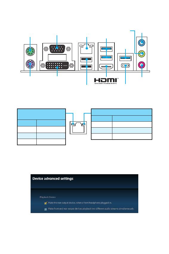
6
/
/
PS/2
PS/2
LAN
USB 3.1
Gen1
Type-A
USB 3.1
Gen1
Type-A
USB 3.1 Gen1
Type-C
USB 2.0
DVI-D
VGA
/
.
. 10 /
100 /
1 /
LAN
Audio 7.1—
7.1
JAUD1. .
1. Realtek HD Audio Manager > Advanced Settings,
, .
2. Mute the rear output device, when a front headphone plugged in.
3. .
.
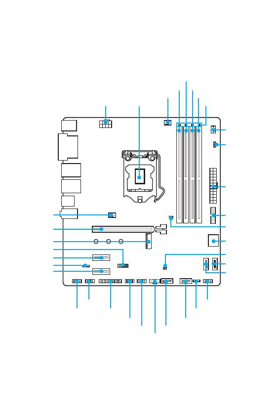
7
/
CPU_FAN1
CPU Socket
PCI_E1
SYS_FAN1
PCI_E2
PCI_E3
M2_1
JCI1
JTPM1
DIMMA1
DIMMA2
DIMMB1
DIMMB2
DIMM LEDs
SYS_FAN2
JUSB1
JBAT1
JLED1
JFP1
JFP2
ATX_PWR1
CPU_PWR1
EZ Debug LED
SATA3
SATA4
SATA5
SATA6JUSB2
JUSB3
JLPT1
JCOM1
JAUD1
JTBT1*
SATA12
* JTBT1 .
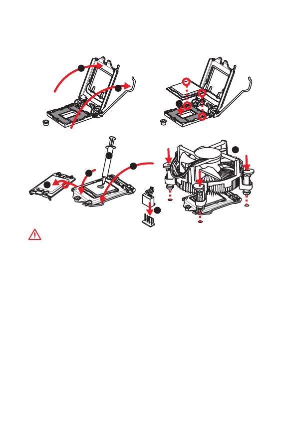
8
/
, ,
.
!
y
,
.
y
,
. ,
, MSI
, .
y
. , ,
.
y
.
y
.
.
( )
.
y
,
.
y
,
. .
1
4
6
5
7
8
9
3
2
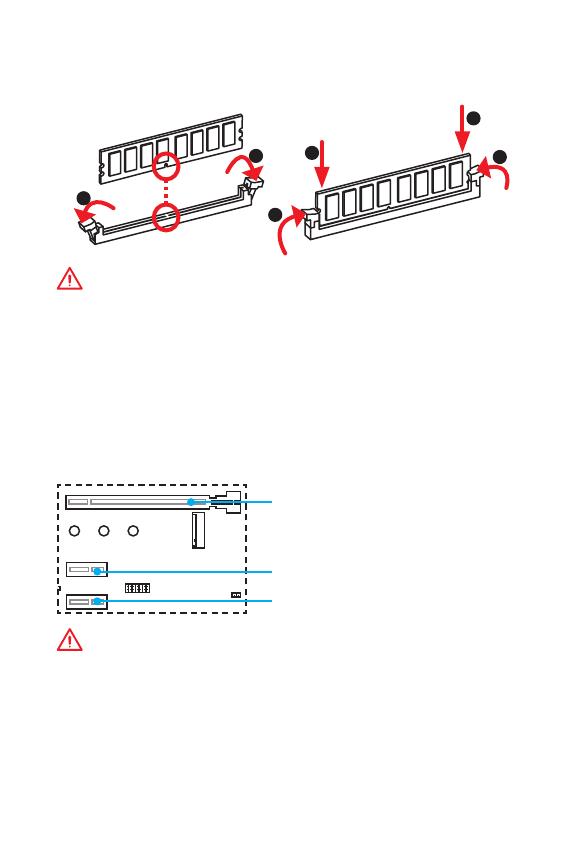
9
/ /
DIMM
, DIMM, .
!
y
DIMMA2 ,
.
y
,
, .
y
, ,
32- Windows, 4 .
4
, 64- Windows.
PCI_E1~3: PCIe
PCI_E1: PCIe 3.0 x16
PCI_E3: PCIe 3.0 x1
PCI_E2: PCIe 3.0 x1
!
,
.
.
1
1
2
3
3
2
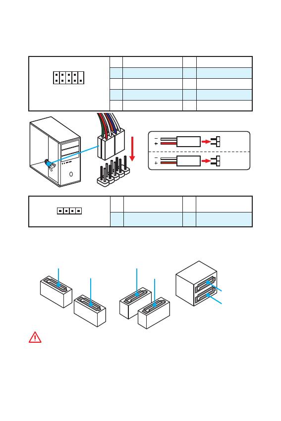
10
/
SATA1~6: SATA 6 /
SATA 6 /.
SATA.
SATA1
SATA2
SATA3
SATA5
SATA4
SATA6
!
y
SATA . ,
.
y
SATA .
,
.
JFP1, JFP2:
, .
1
2 10
9
JFP1
1 HDD LED + 2 Power LED +
3 HDD LED — 4 Power LED —
5 Reset Switch 6 Power Switch
7 Reset Switch 8 Power Switch
9 Reserved 10 No Pin
1
JFP2
1 Speaker — 2 Buzzer +
3 Buzzer — 4 Speaker +
HDD LED
RESET SW
HDD LED
HDD LED —
HDD LED +
POWER LED —
POWER LED +
POWER LED
JFP1
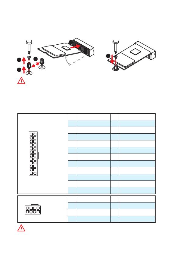
11
/ /
M2_1: M.2 ( M)
, (SSD) M.2 M.2,
.
ATX_PWR1, CPU_PWR1:
ATX.
24
131
12
ATX_PWR1
1 +3.3V 13 +3.3V
2 +3.3V 14 -12V
3 Ground 15 Ground
4 +5V 16 PS-ON#
5 Ground 17 Ground
6 +5V 18 Ground
7 Ground 19 Ground
8 PWR OK 20 Res
9 5VSB 21 +5V
10 +12V 22 +5V
11 +12V 23 +5V
12 +3.3V 24 Ground
5
4
1
8
CPU_PWR1
1 Ground 5 +12V
2 Ground 6 +12V
3 Ground 7 +12V
4 Ground 8 +12V
!
.
1
2
3
4
5
!
Intel
®
RST PCIe M.2 SSD UEFI ROM
Legacy ROM.
30
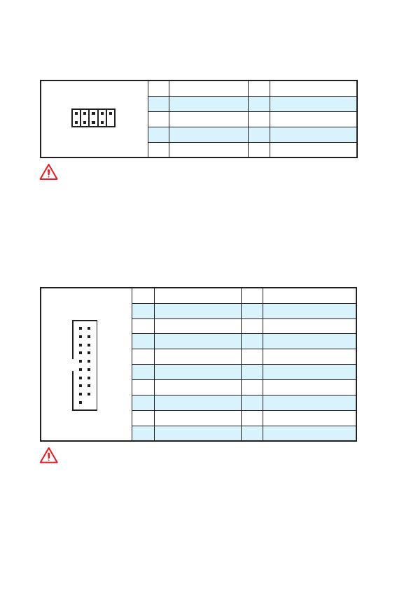
12
/
JUSB1: USB 3.1 Gen1
USB 3.1 Gen1
.
1
10 11
20
1 Power 11 USB2.0+
2 USB3_RX_DN 12 USB2.0-
3 USB3_RX_DP 13 Ground
4 Ground 14 USB3_TX_C_DP
5 USB3_TX_C_DN 15 USB3_TX_C_DN
6 USB3_TX_C_DP 16 Ground
7 Ground 17 USB3_RX_DP
8 USB2.0- 18 USB3_RX_DN
9 USB2.0+ 19 Power
10 NC 20 No Pin
!
, ,
.
JUSB2~3: USB 2.0
USB 2.0
.
1
2 10
9
1 VCC 2 VCC
3 USB0- 4 USB1-
5 USB0+ 6 USB1+
7 Ground 8 Ground
9 No Pin 10 NC
!
y
, ,
VCC .
y
, iPad, iPhone iPod USB,
, MSI
®
SUPER CHARGER.
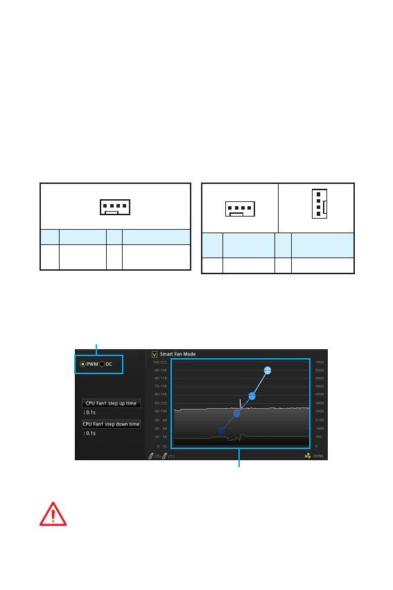
13
/ /
CPU_FAN1, SYS_FAN1~2:
: PWM (PulseWidth
Modulation) .
PWM
12,
.
,
. ,
3- (Non-PWM)
PWM, .
.
1
CPU_FAN1
1 Ground 2 +12V
3 Sense 4
Speed Control
Signal
1
SYS_FAN1
1
SYS_FAN2
1 Ground 2
Voltage
Control
3 Sense 4 NC
PWM
BIOS > HARDWARE MONITOR
: PWM DC, .
PWM DC
!
,
PWM/ DC .
.
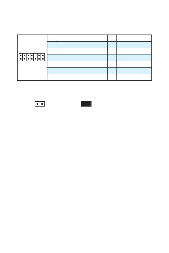
14
/
JTPM1: TPM
(Trusted Platform
Module). . .
1
2 14
13
1 LPC Clock 2 3V Standby power
3 LPC Reset 4 3.3V Power
5 LPC address & data pin0 6 Serial IRQ
7 LPC address & data pin1 8 5V Power
9 LPC address & data pin2 10 No Pin
11 LPC address & data pin3 12 Ground
13 LPC Frame 14 Ground
JCI1:
.
( )
1. JCI1.
2. .
3. BIOS > Security > Chassis Intrusion Configuration.
4. Chassis Intrusion Enabled.
5. F10, ,
Enter, Yes.
6.
.
7. BIOS > Security > Chassis Intrusion Configuration.
8. Chassis Intrusion, Reset.
9. F10, ,
Enter, Yes.
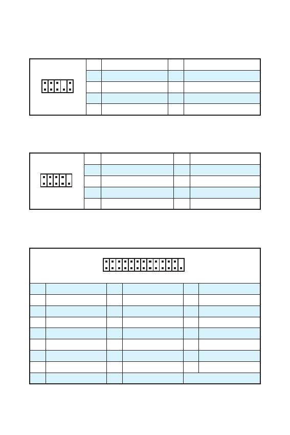
15
/ /
JAUD1:
.
1
2 10
9
1 MIC L 2 Ground
3 MIC R 4 NC
5 Head Phone R 6 MIC Detection
7 SENSE_SEND 8 No Pin
9 Head Phone L 10 Head Phone Detection
JCOM1:
,
.
1
2 10
9
1 DCD 2 SIN
3 SOUT 4 DTR
5 Ground 6 DSR
7 RTS 8 CTS
9 RI 10 No Pin
1
2 26
25
1 RSTB# 2 AFD# 3 PRND0
4 ERR# 5 PRND1 6 PINIT#
7 PRND2 8 LPT_SLIN# 9 PRND3
10 Ground 11 PRND4 12 Ground
13 PRND5 14 Ground 15 PRND6
16 Ground 17 PRND7 18 Ground
19 ACK# 20 Ground 21 BUSY
22 Ground 23 PE 24 Ground
25 SLCT 26 No Pin
JLPT1:
, .
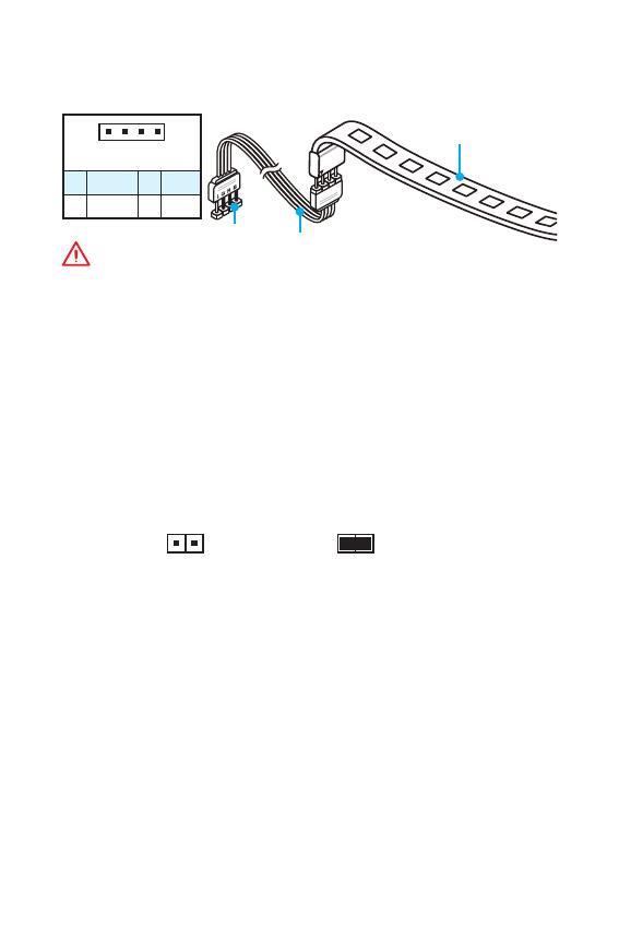
16
/
JBAT1: CMOS (
BIOS)
CMOS
.
( CMOS ), .
( )
/
BIOS
BIOS
1. .
2. ,
JBAT1 5-10 .
3. JBAT1.
4. .
JLED1: RGB LED
RGB.
!
y
5050 RGB
(12/G/R/B) 3 (12).
, 2 ,
.
y
RGB,
.
y
LED Effect GAMING APP
, .
1
JLED1
5050 LED
1
1 +12V 2 G
3 R 4 B

17
/ /
DIMM LEDs — .
PCIe x16 LED — PCIe x16.
[] — x16.
[] — X8, X4, X1.
EZ
LED .
CPU — CPU .
DRAM — DRAM .
VGA — .
BOOT — .
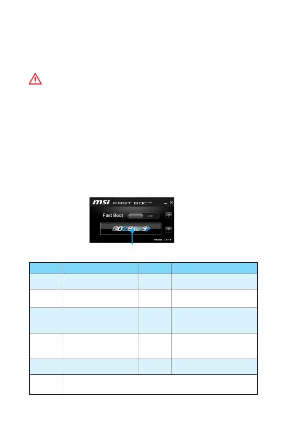
18
BIOS
BIOS
.
BIOS, .
,
.
!
y
, BIOS
.
BIOS .
BIOS,
HELP.
y
.
BIOS
BIOS.
y Delete, Press
DEL key to enter Setup Menu, F11 to enter Boot Menu .
y MSI FAST BOOT. GO2BIOS
OK.
BIOS.
GO2BIOS
F1 F2
/
F3 F4
F5 Memory-Z F6
F7
EZ
F8
F9
F10
*
F12
USB — (
FAT / FAT32 ).
* F10 . Yes
No, .

19
BIOS BIOS
BIOS
BIOS .
:
y BIOS F6
.
y Clear CMOS .
!
BIOS,
CMOS.
BIOS
BIOS M-FLASH
:
, BIOS MSI,
. BIOS
— USB.
BIOS:
1. — USB, .
2. , Del
BIOS POST.
3. BIOS > M-FLASH > Select one file to update BIOS,
BIOS BIOS.
4. ,
.
BIOS Live Update 6
:
,
.
BIOS:
5. MSI LIVE UPDATE 6.
6. Manual scan.
7. MB BIOS Scan.
8. MB BIOS
,
BIOS.
9. Next In Windows mode.
Next Start BIOS.
10. ,
.

20
Windows
®
7/ 8.1/ 10
1. .
2. Windows
®
7/ 8.1/ 10 .
: — ,
Windows
®
7, USB
. MSI Smart Tool
Windows
®
7.
3. Restart .
4. Windows
®
8.1/ 10, . Windows
®
7,
BIOS SETTINGS > Advanced > Windows OS Configuration > Windows
7 Installation ,
.
: Windows
®
7
USB / USB USB, .
5. F11 POST (Power-On Self Test) ,
.
6. .
7. , Press
any key to boot from CD or DVD…
8. , Windows
®
7/ 8.1/ 10.
1. Windows
®
7/ 8.1/ 10.
2. MSI
®
Driver Disc
.
3. ,
.
4. Install.
5. .
.
6. OK .
7. .
.
1. MSI
®
Driver Disc
.
2. .
3. Utilities.
4. .
5. Install
.
6. .
.
7. OK .
8. .
Loading…
![]()
Thank you for purchasing the MSI® H270M PRO-VDH/ B250M PRO-VDH motherboard. This User Guide gives information about board layout, component overview, BIOS setup and software installation.
|
Contents |
|
|
Safety Information………………………………………………………………………………. |
2 |
|
Specifications……………………………………………………………………………………… |
3 |
|
Rear I/O Panel ……………………………………………………………………………………. |
6 |
|
LAN Port LED Status Table …………………………………………………………………….. |
6 |
|
Overview of Components …………………………………………………………………….. |
7 |
|
CPU Socket…………………………………………………………………………………………… |
8 |
|
DIMM Slots …………………………………………………………………………………………… |
9 |
|
PCI_E1~3: PCIe Expansion Slots……………………………………………………………… |
9 |
|
JFP1, JFP2: Front Panel Connectors……………………………………………………… |
10 |
|
SATA1~6: SATA 6Gb/s Connectors…………………………………………………………. |
10 |
|
M2_1: M.2 Slot (Key M)…………………………………………………………………………. |
11 |
|
ATX_PWR1, CPU_PWR1: Power Connectors…………………………………………… |
11 |
|
JUSB2~3: USB 2.0 Connectors ……………………………………………………………… |
12 |
|
JUSB1: USB 3.1 Gen1 Connector…………………………………………………………… |
12 |
|
CPU_FAN1, SYS_FAN1~2: Fan Connectors …………………………………………….. |
13 |
|
JTPM1: TPM Module Connector…………………………………………………………….. |
14 |
|
JCI1: Chassis Intrusion Connector ………………………………………………………… |
14 |
|
JAUD1: Front Audio Connector ……………………………………………………………… |
15 |
|
JCOM1: Serial Port Connector………………………………………………………………. |
15 |
|
JLPT1: Parallel Port Connector…………………………………………………………….. |
15 |
|
JLED1: RGB LED connector………………………………………………………………….. |
16 |
|
JBAT1: Clear CMOS (Reset BIOS) Jumper………………………………………………. |
16 |
|
Onboard LEDs……………………………………………………………………………………… |
17 |
|
BIOS Setup……………………………………………………………………………………….. |
18 |
|
Entering BIOS Setup…………………………………………………………………………….. |
18 |
|
Resetting BIOS ……………………………………………………………………………………. |
19 |
|
Updating BIOS …………………………………………………………………………………….. |
19 |
|
Software Description…………………………………………………………………………. |
20 |
|
Installing Windows® 7/ 8.1/ 10 ………………………………………………………………. |
20 |
|
Installing Drivers…………………………………………………………………………………. |
20 |
|
Installing Utilities ………………………………………………………………………………… |
20 |
Contents 1
Safety Information
yThe components included in this package are prone to damage from electrostatic discharge (ESD). Please adhere to the following instructions to ensure successful computer assembly.
yEnsure that all components are securely connected. Loose connections may cause the computer to not recognize a component or fail to start.
yHold the motherboard by the edges to avoid touching sensitive components.
yIt is recommended to wear an electrostatic discharge (ESD) wrist strap when handling the motherboard to prevent electrostatic damage. If an ESD wrist strap is not available, discharge yourself of static electricity by touching another metal object before handling the motherboard.
yStore the motherboard in an electrostatic shielding container or on an anti-static pad whenever the motherboard is not installed.
yBefore turning on the computer, ensure that there are no loose screws or metal components on the motherboard or anywhere within the computer case.
yDo not boot the computer before installation is completed. This could cause permanent damage to the components as well as injury to the user.
yIf you need help during any installation step, please consult a certified computer technician.
yAlways turn off the power supply and unplug the power cord from the power outlet before installing or removing any computer component.
yKeep this user guide for future reference.
yKeep this motherboard away from humidity.
yMake sure that your electrical outlet provides the same voltage as is indicated on the PSU, before connecting the PSU to the electrical outlet.
yPlace the power cord such a way that people can not step on it. Do not place anything over the power cord.
yAll cautions and warnings on the motherboard should be noted.
yIf any of the following situations arises, get the motherboard checked by service personnel:
Liquid has penetrated into the computer.
The motherboard has been exposed to moisture.
The motherboard does not work well or you can not get it work according to user guide.
The motherboard has been dropped and damaged.
The motherboard has obvious sign of breakage.
yDo not leave this motherboard in an environment above 60°C (140°F), it may damage the motherboard.
2 Safety Information
Specifications
|
CPU |
Supports 6th/ 7th Gen Intel® Core™ i3/i5/i7 processors, and |
|
|
Intel® Pentium® and Celeron® processors for Socket LGA1151 |
||
|
Chipset |
Intel® H270/ B250 Chipset |
|
|
y 4x DDR4 memory slots, support up to 64GB |
||
|
7th Gen processors support DDR4 2400/ 2133 MHz* |
||
|
6th Gen processors support DDR4 2133 MHz* |
||
|
y Dual channel memory architecture |
||
|
Memory |
y Supports Intel® Extreme Memory Profile (XMP)** |
|
|
* Please refer www.msi.com for more information on |
||
|
compatible memory. |
||
|
** DDR4 memory modules can only run at maximum of 2400 |
||
|
MHz for 7th Gen processors and 2133 MHz for 6th Gen |
||
|
processors on XMP mode. |
||
|
Expansion Slots |
y 1x PCIe 3.0 x16 slot (supports x16 mode) |
|
|
y 2x PCIe 3.0 x1 slots |
||
|
y 1x HDMI™ port, supports a maximum resolution of |
||
|
4096×2160@24Hz, 2560×1600@60Hz |
||
|
Onboard Graphics |
y 1x DVI-D port, supports a maximum resolution of |
|
|
1920×1200@60Hz |
||
|
y 1x VGA port, supports a maximum resolution of |
||
|
2048×1536@50Hz, 2048×1280@60Hz, 1920×1200@60Hz |
||
|
Intel® H270/ B250 Chipset |
||
|
y 6x SATA 6Gb/s ports |
||
|
y 1x M.2 slot (Key M) |
||
|
Storage |
Supports up to PCIe 3.0 x4 and SATA 6Gb/s |
|
|
Supports 2242/ 2260 /2280 storage devices |
||
|
Intel® Optane™ Memory Ready |
||
|
y H270 supports RAID 0, RAID1, RAID 5 and RAID 10 for SATA |
||
|
storage devices |
||
|
Intel® H270/ B250 Chipset |
||
|
y 6x USB 3.1 Gen1 (SuperSpeed USB) ports (3 Type-A & 1 |
||
|
USB |
Type-C ports on the back panel, 2 ports available through the |
|
|
internal USB connector) |
||
|
y 6x USB 2.0 (High-speed USB) ports (2 ports on the back |
||
|
panel, 4 ports available through the internal USB connector) |
||
|
Audio |
y Realtek® ALC887 Codec |
|
|
y 7.1-Channel High Definition Audio |
||
|
LAN |
1x Realtek® 8111H Gigabit LAN controller |
|
|
Continued on next page |
Specifications 3
|
Continued from previous page |
||
|
y 1x PS/2 keyboard port |
||
|
y 1x PS/2 mouse port |
||
|
y 1x HDMI™ port |
||
|
y 1x VGA port |
||
|
Back Panel |
y 1x DVI-D port |
|
|
Connectors |
y 1x LAN (RJ45) port |
|
|
y 2x USB 2.0 Type-A ports |
||
|
y 3x USB 3.1 Gen1 Type-A ports |
||
|
y 1x USB 3.1 Gen1 Type-C port |
||
|
y 3x audio jacks |
||
|
y 1x 24-pin ATX main power connector |
||
|
y 1x 8-pin ATX 12V power connector |
||
|
y 6x SATA 6Gb/s connectors |
||
|
y 2x USB 2.0 connectors (supports additional 4 USB 2.0 ports) |
||
|
y 1x USB 3.1 Gen1 connector (supports additional 2 USB 3.1 |
||
|
Gen1 ports) |
||
|
y 1x 4-pin CPU fan connector |
||
|
Internal |
y 2x 4-pin system fan connectors |
|
|
y 1x Front panel audio connector |
||
|
Connectors |
||
|
y 2x Front panel connectors |
||
|
y 1x TPM module connector |
||
|
y 1x Chassis Intrusion connector |
||
|
y 1x Serial port connector |
||
|
y 1x Parallel port connector |
||
|
y 1x RGB LED connecotr |
||
|
y 1x TBT connector |
||
|
y 1x Clear CMOS jumper |
||
|
I/O Controller |
NUVOTON NCT6795 Controller Chip |
|
|
Hardware |
y CPU/System temperature detection |
|
|
y CPU/System fan speed detection |
||
|
Monitor |
||
|
y CPU/System fan speed control |
||
|
Form Factor |
y m-ATX Form Factor |
|
|
y 9.6 in. x 9.0 in. (24.4 cm x 22.8 cm) |
||
|
y 1x 64 Mb flash |
||
|
BIOS Features |
y UEFI AMI BIOS |
|
|
y ACPI 5.0, PnP 1.0a, SM BIOS 2.8 |
||
|
y Multi-language |
||
|
Continued on next page |
4 Specifications
Continued from previous page
|
y Drivers |
||
|
y COMMAND CENTER |
||
|
y LIVE UPDATE 6 |
||
|
y FAST BOOT |
||
|
y SUPER CHARGER |
||
|
y MYSTIC LIGHT |
||
|
Software |
y RAMDISK |
|
|
y X-BOOST |
||
|
y MSI SMART TOOL |
||
|
y NETWORK GENIE |
||
|
y Intel® Extreme Tuning Utility |
||
|
y Norton™ Security |
||
|
y Google Chrome™,Google Toolbar, Google Drive |
||
|
y CPU-Z MSI GAMING |
Specifications 5
|
Rear I/O Panel |
USB 3.1 |
||||
|
Line-out |
Line-in |
||||
|
PS/2 Mouse |
VGA |
LAN |
Gen1 |
||
|
Type-A |
|||||
|
USB 3.1 |
|||||
|
Gen1 |
|||||
|
Type-A |
|||||
|
PS/2 Keyboard |
DVI-D |
Mic in |
|||
|
USB 2.0 |
USB 3.1 Gen1 |
||||
|
Type-C |
LAN Port LED Status Table
Link/ Activity LED
|
Status |
Description |
|
Off |
No link |
|
Yellow |
Linked |
|
Blinking |
Data activity |
Speed LED
|
Status |
Description |
|
Off |
10 Mbps connection |
|
Green |
100 Mbps connection |
|
Orange |
1 Gbps connection |
Audio 7.1-channel Configuration
To configure 7.1-channel audio, you have to connect front audio I/O module to JAUD1 connector and follow the below steps.
1.Click on the Realtek HD Audio Manager > Advanced Settings to open the dialog below.
2.Select Mute the rear output device, when a front headphone plugged in.
3.Plug your speakers to audio jacks on rear and front I/O panel. When you plug into a device at an audio jack, a dialogue window will pop up asking you which device is current connected.
6 Rear I/O Panel
Overview of Components
SYS_FAN1
PCI_E1
M2_1
JTPM1
PCI_E2
JLED1
PCI_E3
|
DIMMA2 |
|||
|
DIMMA1 |
DIMMB1 |
||
|
CPU_FAN1 |
DIMMB2 |
||
|
CPU_PWR1 CPU Socket |
DIMM LEDs |
||
|
SYS_FAN2 |
|||
|
EZ Debug LED |
|||
|
ATX_PWR1 |
|||
|
JUSB1 |
|||
|
JBAT1 |
|||
|
SATA▼1▲2 |
|||
|
JCI1 |
|||
|
SATA3 |
|||
|
SATA4 |
|||
|
JCOM1 |
JFP1 |
||
|
JAUD1 |
JLPT1 |
JFP2 |
|
|
JUSB3 |
SATA5 |
||
|
JUSB2 |
SATA6 |
JTBT1*
* JTBT1 is used to connect a specific card.
Overview of Components 7
CPU Socket
Please install the CPU into the CPU socket as shown below.
2
1
3
8 7
5
4 6
9
Important
yAlways unplug the power cord from the power outlet before installing or removing the CPU.
yPlease retain the CPU protective cap after installing the processor. MSI will deal with Return Merchandise Authorization (RMA) requests if only the motherboard comes with the protective cap on the CPU socket.
yWhen installing a CPU, always remember to install a CPU heatsink. A CPU heatsink is necessary to prevent overheating and maintain system stability.
yConfirm that the CPU heatsink has formed a tight seal with the CPU before booting your system.
yOverheating can seriously damage the CPU and motherboard. Always make sure the cooling fans work properly to protect the CPU from overheating. Be sure to apply an even layer of thermal paste (or thermal tape) between the CPU and the heatsink to enhance heat dissipation.
yWhenever the CPU is not installed, always protect the CPU socket pins by covering the socket with the plastic cap.
yIf you purchased a separate CPU and heatsink/ cooler, Please refer to the documentation in the heatsink/ cooler package for more details about installation.
8 Rear I/O Panel
DIMM Slots
Please install the memory module into the DIMM slot as shown below.
1
3
Important
yTo boot up the system successfully, always insert the memory module into DIMMA2 first.
yDue to chipset resource usage, the available capacity of memory will be a little less than the amount of installed.
yPlease note that the maximum capacity of addressable memory is 4GB or less for 32-bit Windows OS due to the memory address limitation. Therefore, we
recommended that you to install 64-bit Windows OS if you want to install more than 4GB memory on the motherboard.
PCI_E1~3: PCIe Expansion Slots
PCI_E1: PCIe 3.0 x16 slot
PCI_E2: PCIe 3.0 x1 slot
PCI_E3: PCIe 3.0 x1 slot
Important
When adding or removing expansion cards, always turn off the power supply and unplug the power supply power cable from the power outlet. Read the expansion card’s documentation to check for any necessary additional hardware or software changes.
Rear I/O Panel 9
JFP1, JFP2: Front Panel Connectors
These connectors connect to the switches and LEDs on the front panel.
|
2 |
10 |
1 |
HDD LED + |
2 |
Power LED + |
|
|
3 |
HDD LED — |
4 |
Power LED — |
|||
|
1 |
9 |
5 |
Reset Switch |
6 |
Power Switch |
|
|
7 |
Reset Switch |
8 |
Power Switch |
|||
|
JFP1 |
||||||
|
9 |
Reserved |
10 |
No Pin |
HDD LEDSWRESET
JFP1
|
HDD LED |
HDD LED — |
||||||
|
HDD LED + |
|||||||
|
POWER LED — |
|||||||
|
POWER LED |
POWER LED + |
||||||
|
1 |
1 |
Speaker — |
2 |
Buzzer + |
|||||
|
JFP2 |
3 |
Buzzer — |
4 |
Speaker + |
|||||
SATA1~6: SATA 6Gb/s Connectors
These connectors are SATA 6Gb/s interface ports. Each connector can connect to one SATA device.
|
SATA6 |
SATA4 |
|
SATA5 |
SATA3 |
|
SATA2 |
|
|
SATA1 |
Important
yPlease do not fold the SATA cable at a 90-degree angle. Data loss may result during transmission otherwise.
ySATA cables have identical plugs on either sides of the cable. However, it is recommended that the flat connector be connected to the motherboard for space saving purposes.
10 Rear I/O Panel
![]()
M2_1: M.2 Slot (Key M)
Please install the M.2 solid-state drive (SSD) into the M.2 slot as shown below.
|
4 |
|||
|
1 |
3 |
5 |
|
|
30° |
|||
|
2 |
Important
Intel® RST only supports PCIe M.2 SSD with UEFI ROM, does not support Legacy ROM.
ATX_PWR1, CPU_PWR1: Power Connectors
These connectors allow you to connect an ATX power supply.
|
1 |
+3.3V |
13 |
+3.3V |
|||||
|
2 |
+3.3V |
14 |
-12V |
|||||
|
12 |
24 |
3 |
Ground |
15 |
Ground |
|||
|
4 |
+5V |
16 |
PS-ON# |
|||||
|
5 |
Ground |
17 |
Ground |
|||||
|
ATX_PWR1 |
6 |
+5V |
18 |
Ground |
||||
|
7 |
Ground |
19 |
Ground |
|||||
|
8 |
PWR OK |
20 |
Res |
|||||
|
1 |
13 |
9 |
5VSB |
21 |
+5V |
|||
|
10 |
+12V |
22 |
+5V |
|||||
|
11 |
+12V |
23 |
+5V |
|||||
|
12 |
+3.3V |
24 |
Ground |
|
8 |
5 |
1 |
Ground |
5 |
+12V |
|
|
CPU_PWR1 |
2 |
Ground |
6 |
+12V |
||
|
3 |
Ground |
7 |
+12V |
|||
|
4 |
1 |
|||||
|
4 |
Ground |
8 |
+12V |
|||
Important
Make sure that all the power cables are securely connected to a proper ATX power supply to ensure stable operation of the motherboard.
Rear I/O Panel 11
JUSB2~3: USB 2.0 Connectors
These connectors allow you to connect USB 2.0 ports on the front panel.
|
1 |
VCC |
2 |
VCC |
|||||||
|
2 |
10 |
3 |
USB0- |
4 |
USB1- |
|||||
|
5 |
USB0+ |
6 |
USB1+ |
|||||||
|
1 |
9 |
7 |
Ground |
8 |
Ground |
|||||
|
9 |
No Pin |
10 |
NC |
Important
yNote that the VCC and Ground pins must be connected correctly to avoid possible damage.
yIn order to recharge your iPad,iPhone and iPod through USB ports, please install MSI® SUPER CHARGER utility.
JUSB1: USB 3.1 Gen1 Connector
This connector allows you to connect USB 3.1 Gen1 ports on the front panel.
|
1 |
Power |
11 |
USB2.0+ |
|||
|
2 |
USB3_RX_DN |
12 |
USB2.0- |
|||
|
10 |
11 |
3 |
USB3_RX_DP |
13 |
Ground |
|
|
4 |
Ground |
14 |
USB3_TX_C_DP |
|||
|
5 |
USB3_TX_C_DN |
15 |
USB3_TX_C_DN |
|||
|
6 |
USB3_TX_C_DP |
16 |
Ground |
|||
|
7 |
Ground |
17 |
USB3_RX_DP |
|||
|
1 |
20 |
8 |
USB2.0- |
18 |
USB3_RX_DN |
|
|
9 |
USB2.0+ |
19 |
Power |
|||
|
10 |
NC |
20 |
No Pin |
Important
Note that the Power and Ground pins must be connected correctly to avoid possible damage.
12 Rear I/O Panel
CPU_FAN1, SYS_FAN1~2: Fan Connectors
Fan connectors can be classified as PWM (Pulse Width Modulation) Mode and DC Mode. PWM Mode fan connectors provide constant 12V output and adjust fan speed with speed control signal. DC Mode fan connectors control fan speed by changing voltage. Therefore, when you plug a 3-pin (Non-PWM) fan to a PWM Mode fan connector, the fan speed will be always maintained at 100%, and that could be noisy.
PWM Mode fan connector
1
CPU_FAN1
|
1 |
Ground |
2 |
+12V |
|
|
3 |
Sense |
4 |
Speed Control |
|
|
Signal |
||||
DC Mode fan connector
|
1 |
1 |
|||||||||
|
SYS_FAN1 |
||||||||||
|
SYS_FAN2 |
||||||||||
|
1 |
Ground |
2 |
Voltage |
|||||||
|
Control |
||||||||||
|
3 |
Sense |
4 |
NC |
Switching fan mode and adjusting fan speed
You can switch between PWM mode and DC mode and adjust fan speed in BIOS > HARDWARE MONITOR.
Select PWM mode or DC mode
There are gradient points of the fan speed that allow you to adjust fan speed in relation to CPU temperature.
Important
Make sure fans are working properly after switching the PWM/ DC mode.
Rear I/O Panel 13
JTPM1: TPM Module Connector
This connector is for TPM (Trusted Platform Module). Please refer to the TPM security platform manual for more details and usages.
|
1 |
LPC Clock |
2 |
3V Standby power |
|||||||||
|
3 |
LPC Reset |
4 |
3.3V Power |
|||||||||
|
2 |
14 |
5 |
LPC address & data pin0 |
6 |
Serial IRQ |
|||||||
|
7 |
LPC address & data pin1 |
8 |
5V Power |
|||||||||
|
1 |
13 |
9 |
LPC address & data pin2 |
10 |
No Pin |
|||||||
|
11 |
LPC address & data pin3 |
12 |
Ground |
|||||||||
|
13 |
LPC Frame |
14 |
Ground |
JCI1: Chassis Intrusion Connector
This connector allows you to connect the chassis intrusion switch cable.
|
Normal |
Trigger the chassis |
|||
|
(default) |
intrusion event |
Using chassis intrusion detector
1.Connect the JCI1 connector to the chassis intrusion switch/ sensor on the chassis.
2.Close the chassis cover.
3.Go to BIOS > Security > Chassis Intrusion Configuration.
4.Set Chassis Intrusion to Enabled.
5.Press F10 to save and exit and then press the Enter key to select Yes.
6.Once the chassis cover is opened again, a warning message will be displayed on screen when the computer is turned on.
Resetting the chassis intrusion warning
1.Go to BIOS > Security > Chassis Intrusion Configuration.
2.Set Chassis Intrusion to Reset.
3.Press F10 to save and exit and then press the Enter key to select Yes.
14 Rear I/O Panel
JAUD1: Front Audio Connector
This connector allow you to connect audio jacks on the front panel.
|
1 |
MIC L |
2 |
Ground |
|||||||
|
2 |
10 |
3 |
MIC R |
4 |
NC |
|||||
|
5 |
Head Phone R |
6 |
MIC Detection |
|||||||
|
1 |
9 |
7 |
SENSE_SEND |
8 |
No Pin |
|||||
|
9 |
Head Phone L |
10 |
Head Phone Detection |
JCOM1: Serial Port Connector
This connector allows you to connect the optional serial port with bracket.
|
1 |
DCD |
2 |
SIN |
|||||||
|
2 |
10 |
3 |
SOUT |
4 |
DTR |
|||||
|
5 |
Ground |
6 |
DSR |
|||||||
|
1 |
9 |
7 |
RTS |
8 |
CTS |
|||||
|
9 |
RI |
10 |
No Pin |
JLPT1: Parallel Port Connector
This connector allows you to connect the optional parallel port with bracket.
|
2 |
26 |
|||||||||||||||||
|
1 |
25 |
|||||||||||||||||
|
1 |
RSTB# |
2 |
AFD# |
3 |
PRND0 |
|||||||||||||
|
4 |
ERR# |
5 |
PRND1 |
6 |
PINIT# |
|||||||||||||
|
7 |
PRND2 |
8 |
LPT_SLIN# |
9 |
PRND3 |
|||||||||||||
|
10 |
Ground |
11 |
PRND4 |
12 |
Ground |
|||||||||||||
|
13 |
PRND5 |
14 |
Ground |
15 |
PRND6 |
|||||||||||||
|
16 |
Ground |
17 |
PRND7 |
18 |
Ground |
|||||||||||||
|
19 |
ACK# |
20 |
Ground |
21 |
BUSY |
|||||||||||||
|
22 |
Ground |
23 |
PE |
24 |
Ground |
|||||||||||||
|
25 |
SLCT |
26 |
No Pin |
Rear I/O Panel 15
JLED1: RGB LED connector
These connectors allow you to connect the 5050 RGB LED strips.
5050 LED strip
|
1 |
||||
|
1 |
+12V |
2 |
G |
|
|
3 |
R |
4 |
B |
|
|
1 JLED1 |
Extension cable |
|||
|
Important |
yThis connector supports 5050 RGB multi-color LED strips (12V/G/R/B) with the maximum power rating of 3A (12V). Please keeping the LED strip shorter than 2 meters to prevent dimming.
yAlways turn off the power supply and unplug the power cord from the power outlet before installing or removing the RGB LED strip.
yPlease use the LED Effect of GAMING APP to adjust, calibrate and control the LED light, refer to the Software section for details.
JBAT1: Clear CMOS (Reset BIOS) Jumper
There is CMOS memory onboard that is external powered from a battery located on the motherboard to save system configuration data. If you want to clear the system configuration, set the jumpers to clear the CMOS memory.
|
Keep Data |
Clear CMOS/ Reset |
|||
|
(default) |
BIOS |
Resetting BIOS to default values
1.Power off the computer and unplug the power cord
2.Use a jumper cap to short JBAT1 for about 5-10 seconds.
3.Remove the jumper cap from JBAT1.
4.Plug the power cord and power on the computer.
16 Rear I/O Panel
Onboard LEDs
DIMM LEDs — indicate the memory modules are installed.
PCIe x16 slot LED — indicates the PCIe x16 slots status. [Red] — x16 mode. [White] — X8, X4, X1 mode.
EZ Debug LED
These LEDs indicate the status of the motherboard.
CPU — indicates CPU is not detected or fail.
DRAM — indicates DRAM is not detected or fail.
VGA — indicates GPU is not detected or fail.
BOOT — indicates booting device is not detected or fail.
Rear I/O Panel 17
BIOS Setup
The default settings offer the optimal performance for system stability in normal conditions. You should always keep the default settings to avoid possible system damage or failure booting unless you are familiar with BIOS.
Important
yBIOS items are continuous update for better system performance. Therefore, the description may be slightly different from the latest BIOS and should be held for reference only. You could also refer to the HELP information panel for BIOS item description.
yThe pictures in this chapter are for reference only and may vary from the product you purchased.
Entering BIOS Setup
Please refer the following methods to enter BIOS setup.
yPress Delete key, when the Press DEL key to enter Setup Menu, F11 to enter Boot Menu message appears on the screen during the boot process.
yUse MSI FAST BOOT application. Click on GO2BIOS button and choose OK. The system will reboot and enter BIOS setup directly.
Click on GO2BIOS
Function key
|
Key |
Function |
Key |
Function |
|
|
F1 |
General Help |
F2 |
Add/ Remove a favorite item |
|
|
F3 |
Enter Favorites menu |
F4 |
Enter CPU Specifications menu |
|
|
F5 |
Enter Memory-Z menu |
F6 |
Load optimized defaults |
|
|
F7 |
Switch between Advanced mode |
F8 |
Load Overclocking Profile |
|
|
and EZ mode |
||||
|
F9 |
Save Overclocking Profile |
F10 |
Save Change and Reset* |
|
F12 Take a screenshot and save it to USB flash drive (FAT/ FAT32 format only).
* When you press F10, a confirmation window which provides the modification information appears. Select between Yes or No to confirm your choice.
18 BIOS Setup
Resetting BIOS
You might need to restore the default BIOS setting to solve certain problems. There are several ways to reset BIOS:
yGo to BIOS and press F6 to load optimized defaults.
yShort the Clear CMOS jumper on the motherboard.
Important
Please refer to the Clear CMOS jumper section for resetting BIOS.
Updating BIOS
Updating BIOS with M-FLASH
Before updating:
Please download the latest BIOS file that matches your motherboard model from MSI website. And then save the BIOS file into the USB flash drive.
Updating BIOS:
1.Insert the USB flash drive that contains the update file into the computer.
2.Reboot the system, and then press Del key to enter the BIOS Setup during POST.
3.Go to BIOS > M-FLASH > Select one file to update BIOS and ME, select a BIOS file to perform the BIOS update process.
4.After the flashing process is 100% complete, the system will reboot.
Updating the BIOS with Live Update 6
Before updating:
Make sure the LAN driver is already installed and the internet connection is set properly.
Updating BIOS:
1.Install and launch MSI LIVE UPDATE 6.
2.Select Manual scan.
3.Check MB BIOS box and click on Scan button.
|
4. Select the MB BIOS and click on |
icon to download and install the latest BIOS |
|
file. |
5.Click Next and choose In Windows mode. And then click Next and Start to start updating BIOS.
6.After the flashing process is 100% completed, the system will restart automatically.
BIOS Setup 19
Software Description
Installing Windows® 7/ 8.1/ 10
1.Power on the computer.
2.Insert the Windows® 7/ 8.1/ 10 disc into your optical drive.
Note: Due to chipset limitation, during the Windows® 7 installation process, USB optical drives and USB pen drives are not supported. You can use MSI Smart Tool to install Windows® 7.
3.Press the Restart button on the computer case.
4.For windows 8.1/ 10, skip this step. For Windows 7, access the BIOS menu
Advanced > Windows OS Configuration > Windows 7 Installation and set the item to enabled, save changes and restart.
Note: It is suggested to plug in your USB Keyboard/USB Mouse to the leftmost USB port when installing Windows 7.
5.Press F11 key during the computer POST (Power-On Self Test) to get into Boot Menu.
6.Select your optical drive from the Boot Menu.
7.Press any key when screen shows Press any key to boot from CD or DVD…
message.
8.Follow the instructions on the screen to install Windows® 7/ 8.1/ 10.
Installing Drivers
1.Start up your computer in Windows® 7/ 8.1/ 10.
2.Insert MSI® Driver Disc into your optical drive.
3.The installer will automatically appear and it will find and list all necessary drivers.
4.Click Install button.
5.The software installation will then be in progress, after it has finished it will prompt you to restart.
6.Click OK button to finish.
7.Restart your computer.
Installing Utilities
Before you install utilities, you must complete drivers installation.
1.Insert MSI® Driver Disc into your optical drive.
2.The installer will automatically appear.
3.Click Utilities tab.
4.Select the utilities you want to install.
5.Click Install button.
6.The utilities installation will then be in progress, after it has finished it will prompt you to restart.
7.Click OK button to finish.
8.Restart your computer.
20 Software Description
![]()
MSI® H270M PRO-VDH/ B250M PRO-VDH. ,, BIOS .
|
…………………………………………………………………………………………….. |
2 |
|||
|
……………………………………………………………………………………………………. |
3 |
|||
|
I/O ……………………………………………………………………………………….. |
6 |
|||
|
LAN LED ……………………………………………………………………….. |
6 |
|||
|
……………………………………………………………………………………………………. |
7 |
|||
|
CPU ………………………………………………………………………………………………. |
8 |
|||
|
DIMM …………………………………………………………………………………………….. |
9 |
|||
|
PCI_E1~3: PCIe ……………………………………………………………………….. |
9 |
|||
|
JFP1, JFP2: …………………………………………………………………. |
10 |
|||
|
SATA1~6: SATA 6Gb/s ………………………………………………………………… |
10 |
|||
|
M2_1: M.2 |
(Key M) ………………………………………………………………………… |
11 |
||
|
ATX_PWR1, CPU_PWR1: ……………………………………………………… |
11 |
|||
|
JUSB2~3: USB 2.0 ……………………………………………………………………… |
12 |
|||
|
JUSB1: USB 3.1 Gen1 …………………………………………………………………. |
12 |
|||
|
CPU_FAN1, SYS_FAN1~2: ……………………………………………………….. |
13 |
|||
|
JTPM1: TPM ……………………………………………………………………….. |
14 |
|||
|
JCI1: |
…………………………………………………………………………… |
14 |
||
|
JAUD1: |
…………………………………………………………………….. |
15 |
||
|
JCOM1: |
……………………………………………………………………. |
15 |
||
|
JLPT1: ……………………………………………………………………… |
15 |
|||
|
JLED1: RGB LED ……………………………………………………………………….. |
16 |
|||
|
JBAT1: CMOS (Reset BIOS) ………………………………………………….. |
16 |
|||
|
LED………………………………………………………………………………………….. |
17 |
|||
|
BIOS ………………………………………………………………………………………….. |
18 |
|||
|
BIOS |
……………………………………………………………………………………………. |
18 |
||
|
BIOS |
……………………………………………………………………………………………. |
19 |
||
|
BIOS |
……………………………………………………………………………………… |
19 |
||
|
…………………………………………………………………………………..® |
20 |
|||
|
Windows |
7/ 8.1/ 10 ………………………………………………………………… |
20 |
||
|
…………………………………………………………………………………. |
20 |
|||
|
…………………………………………………………………………………. |
20 |
1
y (ESD).
y . ,.
y .
y ESD. ESD ,.
y .
y .
y . ,.
y .
y .
y . y .
y PSU PSU.
y . . y .
y , ..
.
..
.
y 60°C (140°F) . .
2
|
® |
® |
|||||||||||||||
|
6/ 7 |
Gen Intel® Core™ i3/i5/i7 |
LGA1151 |
||||||||||||||
|
CPU |
Intel |
Pentium |
Celeron |
® |
. |
|||||||||||
|
Intel® H270/ B250 |
||||||||||||||||
|
y DDR4 4 , 64GB |
* |
|||||||||||||||
|
7 DDR4 2400/ 2133 MHz |
||||||||||||||||
|
6 DDR4 2133 MHz * |
||||||||||||||||
|
y |
||||||||||||||||
|
y Intel® Extreme Memory Profile (XMP) ** |
||||||||||||||||
|
* |
WWW.MSI. |
|||||||||||||||
|
COM . |
||||||||||||||||
|
** XMP 7 , DDR4 |
||||||||||||||||
|
2400 MHz |
. 6 , |
|||||||||||||||
|
DDR4 2133 MHz . |
||||||||||||||||
|
y PCIe 3.0 x16 1 (x16 ) |
||||||||||||||||
|
y PCIe 3.0 x1 |
2 |
|||||||||||||||
|
y HDMI™ |
1 , 4096×2160@24Hz, 2560×1600@60Hz |
|||||||||||||||
|
y DVI-D |
1 , 1920×1200@60Hz |
|||||||||||||||
|
y VGA 1 , 2048×1536@50Hz, 2048×1280@60Hz, |
||||||||||||||||
|
1920×1200@60Hz |
||||||||||||||||
|
Intel® H270/ B250 |
||||||||||||||||
|
y SATA 6Gb/s |
6 |
|||||||||||||||
|
y M.2 1 (Key M) |
||||||||||||||||
|
2242/ 2260 /2280 |
||||||||||||||||
|
PCIe 3.0 x4 and SATA 6Gb/s |
||||||||||||||||
|
Intel® Optane™ Technology Ready |
(SATA |
|||||||||||||||
|
y H270 RAID 0, RAID1, RAID 5 |
RAID 10 |
|||||||||||||||
|
) |
||||||||||||||||
|
Intel® H270/ B250 |
||||||||||||||||
|
y USB 3.1 Gen1 (SuperSpeed USB) 6 ( |
||||||||||||||||
|
USB |
Type-A 3 & Type-C 1 , USB 2 |
|||||||||||||||
|
) |
||||||||||||||||
|
y USB 2.0 (High-speed USB) 6 ( 2 , |
||||||||||||||||
|
USB 4 ) |
||||||||||||||||
|
y 7.1- HD |
||||||||||||||||
|
y Realtek® ALC887 |
||||||||||||||||
|
LAN |
Realtek® 8111H Gigabit LAN 1 |
|||||||||||||||
3
|
y PS/2 1 |
||||
|
y PS/2 1 |
||||
|
y HDMI™ 1 |
||||
|
y VGA 1 |
||||
|
y DVI-D 1 |
||||
|
y LAN (RJ45) 1 |
||||
|
y USB 2.0 Type-A 2 |
||||
|
y USB 3.1 Gen1 Type-A |
3 |
|||
|
y USB 3.1 Gen1 Type-C |
1 |
|||
|
y 3 |
||||
|
y 24 ATX 1 |
||||
|
y 8 ATX 12V |
1 |
|||
|
y SATA 6Gb/s |
6 |
|||
|
y USB 2.0 2 ( USB 2.0 4 ) |
||||
|
y USB 3.1 Gen1 1 |
( USB 3.1 Gen1 2 ) |
|||
|
y 4- CPU 1 |
||||
|
y 4- 2 |
||||
|
y 1 |
||||
|
y 2 |
||||
|
y TPM 1 |
||||
|
y 1 |
||||
|
y |
1 |
|||
|
y |
1 |
|||
|
y RGB LED 1 |
||||
|
y TBT 1 |
||||
|
y CMOS 1 |
||||
|
I/O |
NUVOTON NCT6795 |
yCPU/y CPU/
yCPU/
|
y m-ATX |
|
|
y 9.6 in. x 9.0 in. (24.4 cm x 22.8 cm) |
|
|
BIOS |
y 64 Mb 1 |
|
y UEFI AMI BIOS |
|
|
y ACPI 5.0, PnP 1.0a, SM BIOS 2.8 |
|
|
y |
|
4
|
y |
|
|
y COMMAND CENTER |
|
|
y LIVE UPDATE 6 |
|
|
y FAST BOOT |
|
|
y SUPER CHARGER |
|
|
y MYSTIC LIGHT |
|
|
y X-BOOST |
|
|
y RAMDISK |
|
|
y MSI SMART TOOL |
|
|
y NETWORK GENIE |
|
|
y Intel® |
|
|
y Norton™ |
|
|
y Google Chrome™,Google Toolbar, Google Drive |
|
|
y CPU-Z MSI GAMING |
5
|
I/O |
USB 3.1 |
||||
|
PS/2 |
VGA |
LAN |
Gen1 |
||
|
Type-A |
USB 3.1 |
||||
|
Gen1 |
|||||
|
Type-A |
|
PS/2 |
DVI |
-D |
||||||||||||||||||||||||||||||||
|
USB 2.0 |
USB 3.1 Gen1 |
|||||||||||||||||||||||||||||||||
|
LAN LED |
Type-C |
|||||||||||||||||||||||||||||||||
|
/ LED |
LED |
|||||||||||||||||||||||||||||||||
|
LAN |
10 Mbps |
|||||||||||||||||||||||||||||||||
|
. |
. |
|||||||||||||||||||||||||||||||||
|
LAN |
100 Mbps |
|||||||||||||||||||||||||||||||||
|
. |
. |
|||||||||||||||||||||||||||||||||
|
LAN |
1 Gbps |
|||||||||||||||||||||||||||||||||
|
. |
. |
7.1
7.1 I/O JAUD1 ..
1.Realtek HD Audio Manager > Advanced Settings( ).
2.[Mute the rear output device, when a front headphone plugged in]() .
3.I/O ..
6 I/O
SYS_FAN1
PCI_E1
M2_1
JTPM1
PCI_E2
JLED1
PCI_E3
|
DIMMA2 |
|||
|
DIMMA1 |
DIMMB1 |
||
|
CPU_PWR1 CPU |
CPU_FAN1 |
DIMMB2 |
|
|
DIMM LEDs |
|||
|
SYS_FAN2 |
|||
|
EZ Debug LED |
|||
|
ATX_PWR1 |
|||
|
JUSB1 |
|||
|
JBAT1 |
|||
|
SATA▼1▲2 |
|||
|
JCI1 |
|||
|
SATA3 |
|||
|
SATA4 |
|||
|
JCOM1 |
JFP1 |
||
|
JAUD1 |
JLPT1 |
JFP2 |
|
|
JUSB3 |
SATA5 |
||
|
JUSB2 |
SATA6 |
JTBT1*
* JTBT1 .
7
CPU
CPU CPU .
2
1
3
8 7
5
4 6
9
yCPU .
y, CPU . CPUMSI (RMA) .
yCPU , CPU . CPU.
yCPU .
yCPU CPU. CPU( ) .
yCPU , CPU.
yCPU / , /.
8 I/O
DIMM
DIMM .
1
3
y DIMMA2 . y .
y 4GB 32- (Windows OS). 4GB 64Windows OS .
PCI_E1~3: PCIe
PCI_E1: PCIe 3.0 x16
PCI_E2: PCIe 3.0 x1
PCI_E3: PCIe 3.0 x1
..
I/O 9
JFP1, JFP2:
LED .
|
2 |
10 |
1 |
HDD LED + |
2 |
Power LED + |
|
|
3 |
HDD LED — |
4 |
Power LED — |
|||
|
1 |
9 |
5 |
Reset Switch |
6 |
Power Switch |
|
|
7 |
Reset Switch |
8 |
Power Switch |
|||
|
JFP1 |
||||||
|
9 |
Reserved |
10 |
No Pin |
HDD LEDSWRESET
JFP1
|
HDD LED |
HDD LED — |
||||||
|
HDD LED + |
|||||||
|
POWER LED — |
|||||||
|
POWER LED |
POWER LED + |
||||||
|
1 |
1 |
Speaker — |
2 |
Buzzer + |
|||||
|
JFP2 |
3 |
Buzzer — |
4 |
Speaker + |
|||||
SATA1~6: SATA 6Gb/s
SATA 6Gb/s . SATA.
SATA2
SATA1
ySATA 90 . , .
ySATA .
10 I/O
![]()
M2_1: M.2 (Key M)
M.2 M.2 solid-state drive (SSD) .
|
4 |
|||
|
1 |
3 |
5 |
|
|
30° |
|||
|
2 |
Intel® RST UEFI ROM PCIe M.2 SSD ROM .
ATX_PWR1, CPU_PWR1:
ATX .
|
1 |
+3.3V |
13 |
+3.3V |
|||||
|
2 |
+3.3V |
14 |
-12V |
|||||
|
12 |
24 |
3 |
Ground |
15 |
Ground |
|||
|
4 |
+5V |
16 |
PS-ON# |
|||||
|
5 |
Ground |
17 |
Ground |
|||||
|
ATX_PWR1 |
6 |
+5V |
18 |
Ground |
||||
|
7 |
Ground |
19 |
Ground |
|||||
|
8 |
PWR OK |
20 |
Res |
|||||
|
1 |
13 |
9 |
5VSB |
21 |
+5V |
|||
|
10 |
+12V |
22 |
+5V |
|||||
|
11 |
+12V |
23 |
+5V |
|||||
|
12 |
+3.3V |
24 |
Ground |
|
8 |
5 |
1 |
Ground |
5 |
+12V |
|
|
CPU_PWR1 |
2 |
Ground |
6 |
+12V |
||
|
3 |
Ground |
7 |
+12V |
|||
|
4 |
1 |
|||||
|
4 |
Ground |
8 |
+12V |
|||
|
ATX |
||||||
|
. |
||||||
|
I/O |
11 |
JUSB2~3: USB 2.0
USB 2.0 .
|
1 |
VCC |
2 |
VCC |
||||||
|
2 |
10 |
3 |
USB0- |
4 |
USB1- |
||||
|
5 |
USB0+ |
6 |
USB1+ |
||||||
|
1 |
9 |
7 |
Ground |
8 |
Ground |
||||
|
9 |
No Pin |
10 |
NC |
yVCC .
yUSB iPad, iPhone iPod MSI® SUPER CHARGER
.
JUSB1: USB 3.1 Gen1
USB 3.1 Gen1 .
|
1 |
Power |
11 |
USB2.0+ |
|||
|
2 |
USB3_RX_DN |
12 |
USB2.0- |
|||
|
10 |
11 |
3 |
USB3_RX_DP |
13 |
Ground |
|
|
4 |
Ground |
14 |
USB3_TX_C_DP |
|||
|
5 |
USB3_TX_C_DN |
15 |
USB3_TX_C_DN |
|||
|
6 |
USB3_TX_C_DP |
16 |
Ground |
|||
|
7 |
Ground |
17 |
USB3_RX_DP |
|||
|
1 |
20 |
8 |
USB2.0- |
18 |
USB3_RX_DN |
|
|
9 |
USB2.0+ |
19 |
Power |
|||
|
10 |
NC |
20 |
No Pin |
.
12 I/O
CPU_FAN1, SYS_FAN1~2:
PWM (Pulse Width Modulation) . PWM 12V. .PWM 3- (Non-PWM) , 100%.
PWM
1
CPU_FAN1
|
1 |
Ground |
2 |
+12V |
|
|
3 |
Sense |
4 |
Speed Control |
|
|
Signal |
||||
DC
|
1 |
1 |
|||||||||
|
SYS_FAN1 |
||||||||||
|
SYS_FAN2 |
||||||||||
|
1 |
Ground |
2 |
Voltage |
|||||||
|
Control |
||||||||||
|
3 |
Sense |
4 |
NC |
PWM DC BIOS > HARDWARE MONITOR
. PWM DC
CPU .
PWM/ DC , .
I/O 13
JTPM1: TPM
TPM (Trusted Platform Module) .
TPM .
|
1 |
LPC Clock |
2 |
3V Standby power |
|||||||||
|
3 |
LPC Reset |
4 |
3.3V Power |
|||||||||
|
2 |
14 |
5 |
LPC address & data pin0 |
6 |
Serial IRQ |
|||||||
|
7 |
LPC address & data pin1 |
8 |
5V Power |
|||||||||
|
1 |
13 |
9 |
LPC address & data pin2 |
10 |
No Pin |
|||||||
|
11 |
LPC address & data pin3 |
12 |
Ground |
|||||||||
|
13 |
LPC Frame |
14 |
Ground |
JCI1:
.
1. JCI1 / . 2. .
3. BIOS > Security( ) > Chassis Intrusion Configuration( )
.
4. Chassis Intrusion( ) Enabled( ) .
5. F10 . Enter Yes . 6. .
1.BIOS > Security( ) > Chassis Intrusion Configuration( ).
2.Chassis Intrusion( ) Reset( ) .
3.F10 . Enter Yes .
14 I/O
JAUD1:
.
|
1 |
MIC L |
2 |
Ground |
|||||||
|
2 |
10 |
3 |
MIC R |
4 |
NC |
|||||
|
5 |
Head Phone R |
6 |
MIC Detection |
|||||||
|
1 |
9 |
7 |
SENSE_SEND |
8 |
No Pin |
|||||
|
9 |
Head Phone L |
10 |
Head Phone Detection |
JCOM1:
.
|
1 |
DCD |
2 |
SIN |
|||||||
|
2 |
10 |
3 |
SOUT |
4 |
DTR |
|||||
|
5 |
Ground |
6 |
DSR |
|||||||
|
1 |
9 |
7 |
RTS |
8 |
CTS |
|||||
|
9 |
RI |
10 |
No Pin |
JLPT1:
.
|
2 |
26 |
|||||||||||||||||
|
1 |
25 |
|||||||||||||||||
|
1 |
RSTB# |
2 |
AFD# |
3 |
PRND0 |
|||||||||||||
|
4 |
ERR# |
5 |
PRND1 |
6 |
PINIT# |
|||||||||||||
|
7 |
PRND2 |
8 |
LPT_SLIN# |
9 |
PRND3 |
|||||||||||||
|
10 |
Ground |
11 |
PRND4 |
12 |
Ground |
|||||||||||||
|
13 |
PRND5 |
14 |
Ground |
15 |
PRND6 |
|||||||||||||
|
16 |
Ground |
17 |
PRND7 |
18 |
Ground |
|||||||||||||
|
19 |
ACK# |
20 |
Ground |
21 |
BUSY |
|||||||||||||
|
22 |
Ground |
23 |
PE |
24 |
Ground |
|||||||||||||
|
25 |
SLCT |
26 |
No Pin |
I/O 15
JLED1: RGB LED
T 5050 RGB LED .
5050 LED
|
1 |
|||||
|
1 |
+12V |
2 |
G |
||
|
3 |
R |
4 |
B |
||
|
1 |
JLED1 |
||||
y 3A (12V) 5050 RGB LED (12V/G/R/B)
. LED 2m . y RGB LED .
y GAMING APP LED Effect LED , .
JBAT1: CMOS (Reset BIOS)
CMOS. CMOS.
|
CMOS |
||||
|
( ) |
/BIOS |
BIOS
1. 2. JBAT1 5-10 .
3. JBAT1 .
4. .
16 I/O
LED
DIMM LEDs — .
PCIe x16 LED — PCIe x16 . [ ] — x16 . [ ] — X8, X4, X1 .
EZ Debug LED (EZ LED )
LED .
CPU — CPU . DRAM — DRAM . VGA — GPU . BOOT — .
I/O 17
BIOS
. BIOS,.
yBIOS .BIOS . BIOS HELP( ) .
y.
BIOS
BIOS .
y Press DEL key to enter Setup Menu, F11 to enter Boot Menu(DEL , F11 )Delete .
y MSI FAST BOOT . GO2BIOS OKBIOS .
GO2BIOS
|
F1 |
F2 |
/ |
|
|
F3 |
F4 |
CPU |
|
|
F5 |
Memory-Z |
F6 |
|
|
F7 |
EZ |
F8 |
|
|
F9 |
F10 |
* |
|
|
F12 |
USB (FAT/ FAT32 ) |
||
|
* F10 |
. Yes |
||
|
No . |
18 BIOS
BIOS
BIOS . BIOS.
y BIOS F6 . y CMOS .
BIOS CMOS .
BIOS
M-FLASH BIOS
BIOS MSI® BIOS USB.
BIOS
1. USB . 2. POST Del BIOS .
3. BIOS > M-FLASH > Select one file to update BIOS and ME , BIOS
BIOS . 4. 100% .
|
Live Update 6 BIOS |
||
|
LAN . |
||
|
BIOS |
||
|
1. |
MSI LIVE UPDATE 6 . |
|
|
2. |
Manual scan . |
|
|
3. |
MB BIOS box Scan . |
|
|
4. |
MB BIOS |
BIOS |
|
. |
||
|
5. |
Next Windows mode Next Start BIOS |
|
|
. |
||
|
6. |
100% . |
BIOS 19
Windows® 7/ 8.1/ 10
1. .
2. Windows® 7/ 8.1/ 10 .
: Windows® 7 USB USB . MSI Smart Tool(MSI ) Windows® 7 .
3. Restart .
4. Windows® 8.1/ 10 , . Windows® 7
, BIOS . Advanced > Windows OS Configuration > Windows 7 Installation [ ].
: Windows 7 , USB USB.
5. POST (Power-On Self Test) F11 .
6. .
7. Press any key to boot from CD or DVD….
8. Windows® 7/ 8.1/ 10 .
1. Windows® 7/ 8.1/ 10 .
2. MSI® .
3. .
4. Install .
5. . . 6. OK .
7. .
. 1. MSI® .
2. .
3. Utilities .
4. .
5. Install .
6. . . 7. OK .
8. .
20
![]()
Merci d’avoir acheté une carte mère MSI® H270M PROVDH/ B250M PRO-VDH. Ce manuel de l’utilisateur fournit des informations sur le schéma, la vue d’ensemble des composants, la configuration du BIOS et l’installation des logiciels.
|
Table des matières |
|
|
Informations de sécurité……………………………………………………………………… |
2 |
|
Spécifications……………………………………………………………………………………… |
3 |
|
Panneau arrière Entrée/ Sortie ……………………………………………………………. |
6 |
|
Tableau explicatif de l’état de la LED du port LAN ……………………………………. |
6 |
|
Vue d’ensemble des composants…………………………………………………………. |
7 |
|
Socket processeur…………………………………………………………………………………. |
8 |
|
Slots DIMM ………………………………………………………………………………………….. |
9 |
|
PCI_E1~3: Slots d’extension PCIe……………………………………………………………. |
9 |
|
JFP1, JFP2: Connecteurs de panneau avant…………………………………………… |
10 |
|
SATA1~6: Connecteurs SATA 6 Gb/s………………………………………………………. |
10 |
|
M2_1: Slot M.2 (Touche M) ……………………………………………………………………. |
11 |
|
ATX_PWR1, CPU_PWR1: Connecteurs d’alimentation…………………………….. |
11 |
|
JUSB2~3: Connecteurs USB 2.0 …………………………………………………………… |
12 |
|
JUSB1: Connecteur USB 3.1 Gen1 ………………………………………………………… |
12 |
|
CPU_FAN1, SYS_FAN1~2: Connecteurs pour ventilateurs ……………………….. |
13 |
|
JTPM1: Connecteur de module TPM ……………………………………………………… |
14 |
|
JCI1: Connecteur intrusion châssis……………………………………………………….. |
14 |
|
JAUD1: Connecteur audio avant ……………………………………………………………. |
15 |
|
JCOM1: Connecteur de port série………………………………………………………….. |
15 |
|
JLPT1: Connecteur de port parallèle……………………………………………………… |
15 |
|
JLED1: Connecteur LED RGB ……………………………………………………………….. |
16 |
|
JBAT1: Cavalier clear CMOS (Réinitialisation BIOS) ………………………………… |
16 |
|
Indicateurs LED embarqués …………………………………………………………………. |
17 |
|
Configuration du BIOS ……………………………………………………………………….. |
18 |
|
Entrer dans l’interface Setup du BIOS…………………………………………………… |
18 |
|
Réinitialiser le BIOS …………………………………………………………………………….. |
19 |
|
Mettre le BIOS à jour……………………………………………………………………………. |
19 |
|
Informations sur les logiciels……………………………………………………………… |
20 |
|
Installer Windows® 7/ 8.1/ 10………………………………………………………………… |
20 |
|
Installer les pilotes………………………………………………………………………………. |
20 |
|
Installer les utilitaires ………………………………………………………………………….. |
20 |
Table des matières 1
Informations de sécurité
yLes composants dans l’emballage peuvent être endommagés par des décharges électrostatiques (ESD). Pour vous assurer de correctement monter votre ordinateur, veuillez vous référer aux instructions ci-dessous.
yAssurez-vous de bien connecter tous les composants. En cas de mauvaise connexion, il se peut que l’ordinateur ne reconnaisse pas le composant et que le démarrage échoue.
yVeuillez tenir la carte mère par les bords pour éviter de toucher les composants sensibles.
yIl est recommandé de porter un bracelet antistatique lors de la manipulation de la carte mère pour prévenir tout dommage. Si vous n’avez pas de bracelet antistatique, touchez un objet métallique relié à la terre avant de manipuler la
carte mère afin de vous décharger de votre charge statique. Touchez régulièrement l’objet métallique pendant toute la manipulation.
yTant que la carte mère n’est pas installée, conservez-la dans un récipient protégé contre les ondes électrostatiques ou sur une couche antistatique.
yAvant de démarrer l’ordinateur, vérifiez si toutes les vis et les composants
métalliques sont bien fixés sur la carte mère ou ailleurs dans le boîtier de l’ordinateur.
yNe démarrez pas l’ordinateur avant d’avoir terminé l’installation. Ceci peut endommager les composants ou vous blesser.
ySi vous avez besoin d’aide pendant l’installation, veuillez consulter un technicien informatique certifié.
yAvant d’installer les composants d’ordinateur, veuillez toujours mettre hors tension et débrancher le cordon d’alimentation.
yGardez ce manuel pour références futures.
yProtégez ce manuel contre l’humidité.
yAvant de brancher le bloc d’alimentation sur la sortie électrique, veuillez vous
assurer que la tension de la sortie électrique est bien égale à celle du bloc d’alimentation.
yPlacez le cordon d’alimentation de façon à éviter que l’on marche dessus. Ne posez rien sur le cordon d’alimentation.
yVeuillez prêter attention à toutes les alertes et remarques indiquées sur la carte mère.
yDans un cas comme ci-dessous, faites appel au service autorisé pour vérifier votre carte mère :
Un liquide a pénétré dans l’ordinateur.
La carte mère a été exposée à de l’humidité.
La carte mère ne fonctionne pas comme indiqué dans les instructions.
La carte mère est tombée par terre et a été endommagée.
La carte mère est cassée.
yNe pas mettre la carte mère dans un environnement dont la température est supérieure à 60°C (140°F) sous peine de l’endommager.
2 Informations de sécurité
Spécifications
|
CPU |
Support des processeurs Intel® Core™ i3/i5/i7, Intel® Pentium® |
|
|
et Celeron® de 6ème ou 7ème génération pour socket LGA1151 |
||
|
Chipset |
Chipset Intel® H270/ B250 |
|
|
y 4 x slots pour mémoire DDR4, support jusqu’à 64 Go |
||
|
Les processeurs de 7ème génération supportent DDR4 |
||
|
2400/ 2133 MHz* |
||
|
Les processeurs de 6ème génération supportent DDR4 |
||
|
2133 MHz* |
||
|
Mémoire |
y Architecture mémoire double canal |
|
|
y Support Intel® Extreme Memory Profile (XMP)** |
||
|
* Veuillez vous référer au site www.msi.com pour plus |
||
|
d’informations sur la mémoire compatible. |
||
|
** Les modules de mémoire DDR4 en mode XMP ne |
||
|
fonctionnent qu’à un taux de transfert maximum de 2400 |
||
|
MHz pour les processeurs de 7ème génération et de 2133 |
||
|
MHz pour les processeurs de 6ème génération. |
||
|
Slots d’extension |
y 1 x slot PCIe 3.0 x16 (support mode x16) |
|
|
y 2 x slots PCIe 3.0 x1 |
||
|
y 1 x port HDMI™, supportant une résolution maximum de |
||
|
4096×2160@24Hz, 2560×1600@60Hz |
||
|
Sorties vidéo |
y 1 x port DVI-D, supportant une résolution maximum de |
|
|
intégrées |
1920×1200@60Hz |
|
|
y 1 x port VGA, supportant une résolution maximum de |
||
|
2048×1536@50Hz, 2048×1280@60Hz, 1920×1200@60Hz |
||
|
Chipset Intel® H270/ B250 |
||
|
y 6 x ports SATA 6 Gb/s |
||
|
y 1 x slot M.2 (Touche M) |
||
|
Stockage |
Support jusqu’à PCIe 3.0 x4 et SATA 6 Gb/s |
|
|
Support des périphériques de stockage 2242/ 2260 /2280 |
||
|
Compatible Intel® Optane™ Technology |
||
|
y H270 supporte RAID 0, RAID1, RAID 5 et RAID 10 pour les |
||
|
périphériques de stockage SATA |
||
|
Chipset Intel® H270/ B250 |
||
|
y 6 x ports USB 3.1 Gen1 SuperSpeed USB (3 ports Type-A et |
||
|
1 port Type-C sur le panneau arrière, 2 ports disponibles par |
||
|
USB |
l’intermédiaire du connecteur USB interne) |
|
|
y 6 x ports USB 2.0 High-speed USB (2 ports sur le panneau |
||
|
arrière, 4 ports disponibles par l’intermédiaire du |
||
|
connecteur USB interne) |
||
|
Suite du tableau sur la page suivante |
Spécifications 3
|
Suite du tableau de la page précédente |
||
|
Audio |
y Codec Realtek® ALC887 |
|
|
y Audio haute définition 7.1 |
||
|
LAN |
1 x contrôleur Realtek® 8111H Gigabit LAN |
|
|
y 1 x port clavier PS/2 |
||
|
y 1 x port souris PS/2 |
||
|
y 1 x port HDMI™ |
||
|
Connecteurs |
y 1 x port VGA |
|
|
y 1 x port DVI-D |
||
|
sur le panneau |
||
|
y 1 x port LAN (RJ45) |
||
|
arrière |
||
|
y 2 x ports USB 2.0 Type-A |
||
|
y 3 x ports USB 3.1 Gen1 Type-A |
||
|
y 1 x port USB 3.1 Gen1 Type-C |
||
|
y 3 x jacks audio |
||
|
y 1 x connecteur d’alimentation principal ATX 24 broches |
||
|
y 1 x connecteur d’alimentation ATX 12V 8 broches |
||
|
y 6 x connecteurs SATA 6 Gb/s |
||
|
y 2 x connecteurs USB 2.0 (support de 4 autres ports USB 2.0) |
||
|
y 1 x connecteur USB 3.1 Gen1 (support de 2 autres ports USB |
||
|
3.1 Gen1) |
||
|
y 1 x connecteur de ventilateurs CPU 4 broches |
||
|
Connecteurs |
y 2 x connecteurs de ventilateurs système 4 broches |
|
|
y 1 x connecteur audio avant |
||
|
internes |
||
|
y 2 x connecteurs de panneau avant |
||
|
y 1 x connecteur de module TPM |
||
|
y 1 x connecteur intrusion châssis |
||
|
y 1 x connecteur de port série |
||
|
y 1 x connecteur de port parallèle |
||
|
y 1 x connecteur RGB LED |
||
|
y 1 x connecteur TBT |
||
|
y 1 x cavalier Clear CMOS |
||
|
Contrôleur E/S |
Contrôleur NUVOTON NCT6795 |
y Détection de la température du CPU et du système Moniteur système y Détection de la vitesse du ventilateur du CPU et du système
y Contrôle de la vitesse du ventilateur du CPU et du système
y Format m-ATX
Dimensions ” ”
y 24,4 cm x 22,8 cm (9,6 x 9,0 )
Suite du tableau sur la page suivante
4 Spécifications
Suite du tableau de la page précédente
|
y 1 x flash BIOS 64 Mb |
||
|
Fonctions BIOS |
y BIOS UEFI AMI |
|
|
y ACPI 5.0, PnP 1.0a, SM BIOS 2.8 |
||
|
y Multilingue |
||
|
y Pilotes |
||
|
y COMMAND CENTER |
||
|
y LIVE UPDATE 6 |
||
|
y FAST BOOT |
||
|
y SUPER CHARGER |
||
|
y MYSTIC LIGHT |
||
|
Logiciel |
y RAMDISK |
|
|
y X-BOOST |
||
|
y MSI SMART TOOL |
||
|
y NETWORK GENIE |
||
|
y Intel® Extreme Tuning Utility |
||
|
y Norton™ Security |
||
|
y Google Chrome™, Google Toolbar et Google Drive |
||
|
y CPU-Z MSI GAMING |
Spécifications 5
|
Panneau arrière Entrée/ Sortie |
||||
|
USB 3.1 |
Ligne-sortie Ligne-entrée |
|||
|
Souris PS/2 |
VGA |
LAN |
Gen1 |
|
|
Type-A |
USB 3.1 |
|||
|
Gen1 |
||||
|
Type-A |
||||
|
Clavier PS/2 |
DVI-D |
Mic entrée |
||
|
USB 2.0 |
USB 3.1 Gen1 |
|||
|
Type-C |
||||
|
Tableau explicatif de l’état de la LED du port LAN |
LED indiquant la connexion et l’activité
|
Etat |
Description |
|
Eteint |
Pas de connexion |
|
Jaune |
Connexion correcte |
|
Clignote |
Activité en cours |
LED indiquant la vitesse
|
Etat |
Description |
|
Eteint |
Débit de 10 Mbps |
|
Vert |
Débit de 100 Mbps |
|
Orange |
Débit de 1 Gbps |
Configuration audio 7.1-canal
Pour régler le système audio 7.1, connectez le module audio entrée/sortie du panneau avant au connecteur JAUD1 et suivez les étapes ci-dessous.
1.Cliquez sur Realtek HD Audio Manager > Advanced Settings (Paramètres avancés) pour ouvrir le dialogue suivant.
2.Choisissez Mute the rear output device, when a front headphone plugged in
(Passer le périphérique arrière en silencieux quand un casque est branché à l’avant).
3.Branchez vos haut-parleurs aux prises audio sur les panneaux entrée/sortie arrière et avant. Lorsqu’un périphérique est branché sur une prise audio, une fenêtre de dialogue apparaîtet vous demande de choisir le périphérique connecté que vous souhaitez utiliser.
6 Panneau arrière Entrée/ Sortie
Vue d’ensemble des composants
SYS_FAN1
PCI_E1
M2_1
JTPM1
PCI_E2
JLED1
PCI_E3
|
DIMMA2 |
|||
|
DIMMA1 |
DIMMB1 |
||
|
Socket |
CPU_FAN1 |
DIMMB2 |
|
|
CPU_PWR1 processeur |
DIMM LEDs |
||
|
SYS_FAN2 |
|||
|
EZ Debug LED |
|||
|
ATX_PWR1 |
|||
|
JUSB1 |
|||
|
JBAT1 |
|||
|
SATA▼1▲2 |
|||
|
JCI1 |
|||
|
SATA3 |
|||
|
SATA4 |
|||
|
JCOM1 |
JFP1 |
||
|
JAUD1 |
JLPT1 |
JFP2 |
|
|
JUSB3 |
SATA5 |
||
|
JUSB2 |
SATA6 |
JTBT1*
* Le port JTBT1 vous permet de connecter une carte additionnelle.
Vue d’ensemble des composants 7
Socket processeur
Installer le CPU dans le socket du processeur comme indiqué ci-dessous.
2
1
3
8 7
5
4 6
9
Important
yAvant d’installer ou de retirer le processeur du socket, veillez à toujours débrancher le câble d’alimentation de la prise électrique.
yVeuillez garder le capot de protection du processeur après l’installation du
processeur. Selon les exigences de RMA (Return Merchandise Authorization), MSI n’acceptera pas les cartes mère dont le capot de protection aura été retiré.
yLors de l’installation d’un processeur, n’oubliez pas d’installer un ventilateur pour processeur. Un ventilateur de processeur est nécessaire pour protéger le processeur contre la surchauffe et maintenir la stabilité du système.
yAssurez-vous de l’étanchéité entre le ventilateur et le processeur avant de démarrer votre système.
yLa surchauffe peut facilement endommager le processeur et la carte mère.
Assurez-vous toujours que le système de refroidissement fonctionne correctement pour protéger le processeur de la surchauffe. Assurez-vous d’appliquer une
couche de pâte thermique (ou adhésif thermique) entre le processeur et le système de refroidissement afin d’améliorer la dissipation de la chaleur.
yQuand le processeur n’est pas installé, protégez toujours les broches de l’emplacement du processeur avec le couvercle dédié.
ySi vous avez achetez un processeur indépendamment du ventilateur, veuillez vous référer à la documentation dans le paquet du ventilateur pour plus d’informations concernant l’installation.
8 Vue d’ensemble des composants
Slots DIMM
Insérer le module de mémoire dans l’emplacement DIMM comme indiqué cidessous.
1
3
Important
yPour réussir à démarrer le système, veuillez à toujours insérer un module de mémoire dans l’emplacement DIMMA2 en premier.
yDu fait des ressources utilisées par le chipset, la capacité de mémoire disponible est un peu moins élevée que celle installée.
yVeuillez noter que la capacité maximum de la mémoire est de 4 Go ou moins pour le système d’exploitation Windows 32-bit du fait de la limitation de mémoire. Par conséquent, il est recommandé d’installer le système d’exploitation Windows 64bit si vous voulez installer une mémoire de plus de 4 Go sur la carte mère.
PCI_E1~3: Slots d’extension PCIe
PCI_E1: slot PCIe 3.0 x16
PCI_E2: slot PCIe 3.0 x1
PCI_E3: slot PCIe 3.0 x1
Important
Veillez à toujours mettre l’ordinateur hors tension et à débrancher le cordon d’alimentation avant d’installer les cartes d’extension. Référez-vous à la documentation des cartes pour vérifier si un composant ou un logiciel doit être modifié.
Vue d’ensemble des composants 9
JFP1, JFP2: Connecteurs de panneau avant
Ces connecteurs se lient aux interrupteurs et indicateurs LED du panneau avant.
|
2 |
10 |
1 |
HDD LED + |
2 |
Power LED + |
|
|
3 |
HDD LED — |
4 |
Power LED — |
|||
|
1 |
9 |
5 |
Reset Switch |
6 |
Power Switch |
|
|
7 |
Reset Switch |
8 |
Power Switch |
|||
|
JFP1 |
||||||
|
9 |
Reserved |
10 |
No Pin |
HDD LEDSWRESET
JFP1
|
HDD LED |
HDD LED — |
||||||
|
HDD LED + |
|||||||
|
POWER LED — |
|||||||
|
POWER LED |
POWER LED + |
||||||
|
1 |
1 |
Speaker — |
2 |
Buzzer + |
|||||
|
JFP2 |
3 |
Buzzer — |
4 |
Speaker + |
|||||
SATA1~6: Connecteurs SATA 6 Gb/s
Ces connecteurs utilisent une interface SATA 6 Gb/s. Chaque connecteur peut être relié à un appareil SATA.
SATA2
SATA1
Important
yVeuillez ne pas plier le câble SATA à 90° car cela pourrait entraîner une perte de données pendant la transmission.
yLes câbles SATA disposent de prises identiques sur chaque côté. Néanmoins, il est recommandé de connecter la prise plate sur la carte mère pour un gain d’espace.
10 Vue d’ensemble des composants
Смотреть руководство для MSI B250M PRO-VDH ниже. Все руководства на ManualsCat.com могут просматриваться абсолютно бесплатно. Нажав кнопку «Выбор языка» вы можете изменить язык руководства, которое хотите просмотреть.

MANUALSCAT | RU
Вопросы и ответы
У вас есть вопрос о MSI B250M PRO-VDH, но вы не можете найти ответ в пользовательском руководстве? Возможно, пользователи ManualsCat.com смогут помочь вам и ответят на ваш вопрос. Заполните форму ниже — и ваш вопрос будет отображаться под руководством для MSI B250M PRO-VDH. Пожалуйста, убедитесь, что вы опишите свои трудности с MSI B250M PRO-VDH как можно более детально. Чем более детальным является ваш вопрос, тем более высоки шансы, что другой пользователь быстро ответит на него. Вам будет автоматически отправлено электронное письмо, чтобы проинформировать вас, когда кто-то из пользователей ответит на ваш вопрос.
Задать вопрос о MSI B250M PRO-VDH
Страница: 1
1
Содержание
Содержание
Безопасное использование продукции…………………………………………2
Технические характеристики…………………………………………………………3
Задняя панель портов ввода/ вывода …………………………………………..6
Таблица состояний индикатора порта LAN………………………………………..6
Компоненты материнской платы…………………………………………………..7
Процессорный сокет…………………………………………………………………………..8
Слоты DIMM…………………………………………………………………………………………9
PCI_E1~3: Слоты расширения PCIe ……………………………………………………..9
JFP1, JFP2: Разъемы передней панели……………………………………………..10
SATA1~6: Разъемы SATA 6 Гб/с…………………………………………………………….10
M2_1: Слот M.2 (Ключ M)…………………………………………………………………….11
ATX_PWR1, CPU_PWR1: Разъемы электропитания …………………………….11
JUSB2~3: Разъемы USB 2.0 …………………………………………………………………12
JUSB1: Разъем USB 3.1 Gen1……………………………………………………………….12
CPU_FAN1, SYS_FAN1~2: Разъемы вентиляторов ………………………………13
JTPM1: Разъем модуля TPM……………………………………………………………….14
JCI1: Разъем датчика открытия корпуса…………………………………………..14
JAUD1: Разъем аудио передней панели ……………………………………………15
JCOM1: Разъем последовательного порта………………………………………..15
JLPT1: Разъем параллельного порта ………………………………………………..15
JLED1: Разъем RGB LED ……………………………………………………………………..16
JBAT1: Джампер очистки данных CMOS (Сброс BIOS)………………………..16
Встроенные индикадоры………………………………………………………………….17
Настройка BIOS ………………………………………………………………………………18
Вход в настройки BIOS………………………………………………………………………18
Сборс BIOS…………………………………………………………………………………………19
Обновление BIOS ………………………………………………………………………………19
Описание программного обеспечения………………………………………..20
Установка Windows®
7/ 8.1/ 10……………………………………………………………20
Установка драйверов………………………………………………………………………..20
Установка утилит………………………………………………………………………………20
Благодарим Вас за покупку материнской платы MSI®
H270M PRO-VDH/ B250M PRO-VDH. Данное руководство
пользователя содержит информацию о схеме платы,
компонентах материнской платы, настройке BIOS и
описание программного обеспечения.
Страница: 2
2 Безопасное использование продукции
Безопасное использование продукции
y Компоненты, входящие в комплект поставки могут быть повреждены
статическим электричеством. Для успешной сборки компьютера,
пожалуйста, следуйте указаниям ниже.
y Убедитесь, что все компоненты компьютера подключены должным
образом. Ослабленные соединения компонентов могут привести как к
сбоям в работе, так и полной неработоспособности компьютера.
y Чтобы избежать повреждений компонентов платы всегда держите ее за
края.
y При сборке комьютера рекомендуется пользоваться электростатическим
браслетом. В случае, если это невозможно, перед работой с платой
снимите электростатический заряд со своего тела, прикоснувшись к
металлическому предмету.
y В случае, если материнская плата не установлена в корпус, храните ее в
антистатической упаковке или на антистатическом коврике.
y Перед включением компьютера убедитесь, что все винты крепления
и другие металлические компоненты на материнской плате и внутри
корпуса надежно зафиксированы.
y Не включайте компьютер, если сборка не завершена. Это может привести
к повреждению компонентов, а также травмированию пользователя.
y Если вам нужна помощь на любом этапе сборки компьютера, пожалуйста,
обратитесь к сертифицированному компьютерному специалисту.
y Всегда выключайте питание и отсоединяйте шнур питания от
электрической розетки перед установкой или удалением любого
компонента компьютера.
y Сохраните это руководство для справки.
y Не допускайте воздействия на материнскаую плату высокой влажности.
y Перед тем как подключить блок питания компьютера к электрической
розетке убедитесь, что напряжение электросети соответствует
напряжению, указанному на блоке питания.
y Располагайте шнур питания так, чтобы на него не могли наступить люди.
Не ставьте на шнур питания никаких предметов.
y Необходимо учитывать все предостережения и предупреждения,
указанные на материнской плате.
y При возникновении любой из перечисленных ниже ситуаций обратитесь
в сервисный центр для проверки материнской платы:
y Попадание жидкости внутрь компьютера.
y Материнская плата подверглась воздействию влаги.
y Материнская плата не работает должным образом или невозможно
наладить ее работу в соответствии с руководством пользователя.
y Материнская плата получила повреждения при падении.
y Материнская плата имеет явные признаки повреждения.
y Не храните материнскую плату в местах с температурой выше 60°C (140°F),
так как это может привести к ее повреждению.
Страница: 3
3
Технические характеристики
Технические характеристики
Процессор
Поддержка процессоров Intel®
Core™
i3/i5/i7, Intel®
Pentium®
и Celeron®
6-го/ 7-го поколения для сокета
LGA1151
Чипсет Intel®
H270/ B250
Память
y 4x DDR4 слота памяти с поддержкой до 64ГБ
Процессоры 7-ого поколения поддерживают DDR4
2400/ 2133 МГц*
Процессоры 6-ого поколения поддерживают DDR4
2133 МГц*
y Двухканальная архитектура памяти
y Поддержка Intel®
Extreme Memory Profile (XMP)**
* Пожалуйста, обратитесь www.msi.com для получения
дополнительной информации о совместимых
памяти.
** Модули памяти DDR4 2400 МГц будут работать на
максимальной частоте 2400 МГц для процессоров
7-ого поколения и на 2133 МГц для процессоров
6-ого поколения в режиме XMP.
Слоты
расширения
y 1x слот PCIe 3.0 x16 (Поддержка режима x16)
y 2x слота PCIe 3.0 x1
Встроенная
графика
y 1x порт HDMI™
, с поддержкой максимального
разрешения 4096×2160@24Гц, 2560×1600@60Гц
y 1x порт DVI-D, с поддержкой максимального
разрешения 1920×1200@60Гц
y 1x порт VGA, с поддержкой максимального
разрешения 2048×1536@50Гц, 2048×1280@60Гц,
1920×1200@60Гц
Подключение
накопителей
Чипсет Intel®
H270/ B250
y 6x портов SATA 6Гб/с
y 1x слот M.2 (Ключ M)
Поддержка PCIe 3.0 x4 и SATA 6Гб/с
Поддержка накопителей 2242/ 2260 /2280
Поддержка Intel®
Optane™
Technology
y H270 поддерживает RAID 0, RAID1, RAID 5 и RAID 10 для
устройств SATA.
Продолжение на следующей странице
Страница: 4
4 Технические характеристики
Продолжение с предыдущей страницы
USB
Контроллер Intel®
H270/ B250
y 6x портов USB 3.1 Gen1 (SuperSpeed USB) (3 порта Type-A
& 1 порт Type-C на задней панели, 2 порта доступны
через внутренние USB разъемы)
y 6x портов USB 2.0 (High-speed USB) (2 порта на задней
панели, 4 порта доступны через внутренние USB
разъемы)
Аудио
y Realtek®
ALC887 Codec
y 7.1-канальный High Definition Audio
LAN 1x Гигабитный сетевой контроллер Realtek®
8111H
Разъемы
задней панели
y 1x порт PS/2 клавиатура
y 1x порт PS/2 мышь
y 1x порт HDMI™
y 1x порт VGA
y 1x порт DVI-D
y 1x порт LAN (RJ45)
y 2x порта USB 2.0 Type-A
y 3x порта USB 3.1 Gen1 Type-A
y 1x порт USB 3.1 Gen1 Type-C
y 3x аудиоразъема
Разъемы на
плате
y 1x 24-контактный разъем питания ATX
y 1x 8-контактный разъем питания ATX 12В
y 6x разъемов SATA 6 Гб/с
y 2x разъема USB 2.0 (Поддержка 4-х дополнительных
портов USB 2.0)
y 1x разъем USB 3.1 Gen1 (Поддержка 2-х
дополнительных портов USB 3.1 Gen1)
y 1x 4-контактный разъем вентилятора процессора
y 2x 4-контактных разъема вентилятора системы
y 1x аудиоразъем передней панели
y 2x разъема передней панели
y 1x разъем TPM
y 1x разъем датчика открытия корпуса
y 1x разъем последовательного порта
y 1x разъем параллельного порта
y 1x разъем RGB LED
y 1x разъем TBT
y 1x джампер очистки данных CMOS
Продолжение на следующей странице
Страница: 5
5
Технические характеристики
Продолжение с предыдущей страницы
Контроллер
ввода-вывода
NUVOTON NCT6795
Аппаратный
мониторинг
y Определение температуры процессора/системы
y Определение скорости вентиляторов процессора/
системы
y Управление скоростью вентиляторов процессора/
системы
Форм-фактор
y m-ATX Форм-фактор
y 9.6 x 9.0 дюйма (24.4 x 22.8 см)
Параметры
BIOS
y 1x 64 Мб флэш
y UEFI AMI BIOS
y ACPI 5.0, PnP 1.0a, SM BIOS 2.8
y Мультиязычный интерфейс
Программное
обеспечение
y Драйверы
y COMMAND CENTER
y LIVE UPDATE 6
y FAST BOOT
y SUPER CHARGER
y MYSTIC LIGHT
y RAMDISK
y X-BOOST
y MSI SMART TOOL
y NETWORK GENIE
y Intel®
Extreme Tuning Utility
y Norton™
Security
y Google Chrome™
,Google Toolbar, Google Drive
y CPU-Z MSI GAMING
Страница: 6
6 Задняя панель портов ввода/ вывода
Задняя панель портов ввода/ вывода
PS/2 мышь
PS/2 клавиатура
LAN
USB 3.1
Gen1
Type-A
USB 3.1
Gen1
Type-A
USB 3.1 Gen1
Type-C
USB 2.0
DVI-D
VGA
Линейный
вход
Линейный
выход
Микрофонный
вход
Подключение/ Работа
индикатора
Состояние Описание
Выкл. Не подключен
Желтый Подключен
Мигает Передача данных
Скорость передачи данных
Состояние Описание
Выкл. 10 Мбит/с подключение
Зеленый 100 Мбит/с подключение
Оранжевый 1 Гбит/с подключение
Таблица состояний индикатора порта LAN
Audio 7.1—конфигурация каналов
Для настройки 7.1 канального аудио необходимо подключить фронтальную
звуковую панель к разъему JAUD1. Далее следуйте указаниям ниже.
1. Нажмите на Realtek HD Audio Manager > Advanced Settings, чтобы открыть
диалоговое окно, как показано ниже.
2. Выберите Mute the rear output device, when a front headphone plugged in.
3. Подключите колонки к аудио разъемам на задней и передней панели.
При подключении устройства к разъему аудио появится диалоговое
окно с просьбой подтвердить подключенное устройство.
Страница: 7
7
Компоненты материнской платы
Компоненты материнской платы
CPU_FAN1
CPU Socket
PCI_E1
SYS_FAN1
PCI_E2
PCI_E3
M2_1
JCI1
JTPM1
DIMMA1
DIMMA2
DIMMB1
DIMMB2
DIMM LEDs
SYS_FAN2
JUSB1
JBAT1
JLED1
JFP1
JFP2
ATX_PWR1
CPU_PWR1
EZ Debug LED
SATA3
SATA4
SATA5
SATA6
JUSB2
JUSB3
JLPT1
JCOM1
JAUD1
JTBT1*
SATA▼1▲2
* JTBT1 используется для подключения специальной карты.
Страница: 8
8 Задняя панель портов ввода/ вывода
Процессорный сокет
Пожалуйста, установите процессор в процессорный сокет, как показано
ниже.
Внимание!
y Перед установкой или заменой процессора, необходимо отключить
кабель питания.
y Пожалуйста, сохраните защитную крышку процессорного сокета
после установки процессора. Любые возможные гарантийные случаи,
связанные с работой материнской платы, MSI будет рассматривать
только, при наличии защитной крышки на процессорном сокете.
y При установке процессора обязательно установите процессорный
кулер. Кулер, представляющий собой систему охлаждения процессора,
предупреждает перегрев и обеспечивает стабильную работу системы.
y Перед включением системы проверьте герметичность соединения между
процессором и радиатором.
y Перегрев может привести к серьезному повреждению процессора и
материнской платы. Всегда проверяйте работоспособность вентилятора
для защиты процессора от перегрева. При установке кулера нанесите
ровный слой термопасты (или термоленту) на крышку установленного
процессора для улучшения теплопередачи.
y Если процессор не установлен, всегда защищайте контакты
процессорного сокета пластиковой крышкой.
y Если вы приобрели отдельно процессор и процессорный кулер,
подробное описание установки см. в документации в данному кулеру.
1
4
6
5
7
8
9
3
2
Страница: 9
9
Задняя панель портов ввода/ вывода
Слоты DIMM
Пожалуйста, установите модуль памяти в слот DIMM, как показано ниже.
Внимание!
y Всегда вставьте модуль памяти в DIMMA2 в первую очередь, чтобы систему
успешно запустить.
y В связи со спецификой использования ресурсов чипсета, доступный
объем памяти будет немного меньше, чем объем установленный.
y Пожалуйста, обратите внимание на то, что максимальная емкость
адресуемой памяти для 32-бит ОС Windows, составляет не более 4 ГБ. Если
вы хотите использовать более 4ГБ оперативной памяти на материнской
плате, рекомендуется устанавливать 64-бит ОС Windows.
PCI_E1~3: Слоты расширения PCIe
PCI_E1: слот PCIe 3.0 x16
PCI_E3: слот PCIe 3.0 x1
PCI_E2: слот PCIe 3.0 x1
Внимание!
Перед установкой или извлечением плат расширения убедитесь, что кабель
питания отключен от электрической сети. Прочтите документацию на карту
расширения и выполните необходимые дополнительные аппаратные или
программные изменения для данной карты.
1
1 2
3
3
2
Страница: 10
10 Задняя панель портов ввода/ вывода
SATA1~6: Разъемы SATA 6 Гб/с
Эти разъемы представляют собой интерфейсные порты SATA 6 Гб/с. К
каждому порту можно подключить одно устройство SATA.
SATA1
SATA2
SATA3
SATA5
SATA4
SATA6
Внимание!
y Избегайте перегибов кабеля SATA под прямым углом. В противном случае,
возможна потеря данных при передаче.
y Кабели SATA оснащены одинаковыми коннекторами с обеих сторон.
Однако, для экономии занимаемого пространства к материнской плате
рекомендуется подключать плоский разъем.
JFP1, JFP2: Разъемы передней панели
Эти разъемы служат для подключения кнопок и светодиодных
индикаторов, расположенных на передней панели.
1
2 10
9
JFP1
1 HDD LED + 2 Power LED +
3 HDD LED — 4 Power LED —
5 Reset Switch 6 Power Switch
7 Reset Switch 8 Power Switch
9 Reserved 10 No Pin
1
JFP2
1 Speaker — 2 Buzzer +
3 Buzzer — 4 Speaker +
HDD
LED
RESET
SW
HDD LED
HDD LED —
HDD LED +
POWER LED —
POWER LED +
POWER LED
J
F
P
1
Страница: 11
11
Задняя панель портов ввода/ вывода
M2_1: Слот M.2 (Ключ M)
Пожалуйста, установите твердотельный накопитель (SSD) M.2 в слот M.2, как
показано ниже.
ATX_PWR1, CPU_PWR1: Разъемы электропитания
Данные разъемы предназначены для подключения коннекторов питания
ATX.
24
13
1
12
ATX_PWR1
1 +3.3V 13 +3.3V
2 +3.3V 14 -12V
3 Ground 15 Ground
4 +5V 16 PS-ON#
5 Ground 17 Ground
6 +5V 18 Ground
7 Ground 19 Ground
8 PWR OK 20 Res
9 5VSB 21 +5V
10 +12V 22 +5V
11 +12V 23 +5V
12 +3.3V 24 Ground
5
4 1
8
CPU_PWR1
1 Ground 5 +12V
2 Ground 6 +12V
3 Ground 7 +12V
4 Ground 8 +12V
Внимание!
Для обеспечения стабильной работы системной платы проверьте
надежность подключения всех кабелей питания к блоку питания АТХ.
1
2
3
4
5
Внимание!
Intel®
RST поддерживает только PCIe M.2 SSD с UEFI ROM и не поддерживает
устройства с Legacy ROM.
30°
Страница: 12
12 Задняя панель портов ввода/ вывода
JUSB1: Разъем USB 3.1 Gen1
Данный разъем предназначен для подключения портов USB 3.1 Gen1 на
передней панели.
1
10 11
20
1 Power 11 USB2.0+
2 USB3_RX_DN 12 USB2.0-
3 USB3_RX_DP 13 Ground
4 Ground 14 USB3_TX_C_DP
5 USB3_TX_C_DN 15 USB3_TX_C_DN
6 USB3_TX_C_DP 16 Ground
7 Ground 17 USB3_RX_DP
8 USB2.0- 18 USB3_RX_DN
9 USB2.0+ 19 Power
10 NC 20 No Pin
Внимание!
Помните, что во избежание повреждений, необходимо правильно
подключать контакты питания и земли.
JUSB2~3: Разъемы USB 2.0
Данные разъемы предназначены для подключения портов USB 2.0 на
передней панели.
1
2 10
9
1 VCC 2 VCC
3 USB0- 4 USB1-
5 USB0+ 6 USB1+
7 Ground 8 Ground
9 No Pin 10 NC
Внимание!
y Помните, что во избежание повреждений, необходимо правильно
подключать контакты VCC и земли.
y Для того, чтобы зарядить ваш iPad, iPhone и iPod через порты USB,
пожалуйста, установите утилиту MSI®
SUPER CHARGER.
Страница: 13
13
Задняя панель портов ввода/ вывода
CPU_FAN1, SYS_FAN1~2: Разъемы вентиляторов
Разъемы вентиляторов можно разделить на два типа: с PWM (PulseWidth
Modulation) управлением и управлением постоянным током. Разъемы
вентиляторов с PWM управлением имеют контакт с постоянным
напряжением 12В, а также контакт с сигналом управления скоростью
вращения. Управление скоростью вращения вентиляторов с управлением
постоянным током, осуществляется через соответсвующие разъемы
путем изменения величины напряжения. Поэтому, при подключении
3-х контактного (Non-PWM) вентилятора к разъему для вентилятора
PWM, скорость вентилятора всегда будет максимальной. Работа такого
вентилятора может оказаться достаточно шумной.
1
CPU_FAN1
1 Ground 2 +12V
3 Sense 4
Speed Control
Signal
1
SYS_FAN1
1
SYS_FAN2
1 Ground 2
Voltage
Control
3 Sense 4 NC
Разъем вентилятора с PWM управлением
Разъем вентилятора с управлением
постоянным током
Переключение режимов работы и скорости вращения
вентилятора
В меню BIOS > HARDWARE MONITOR вы можете выбрать режим работы
вентилятора: PWM или DC, а также настроить его скорость вращения.
Выберите режим PWM или режим DC
Внимание!
Убедитесь, что вентиляторы работают правильно после выбора режима
PWM/ DC .
Вы можете регулировать скорость вращения
вентилятора в зависимости от температуры процессора
путем изменения положения градиентных точек.
Страница: 14
14 Задняя панель портов ввода/ вывода
JTPM1: Разъем модуля TPM
Данный разъем используется для подключения модуля ТРМ (Trusted Platform
Module). Дополнительные сведения см. в описании модуля ТРМ.
1
2 14
13
1 LPC Clock 2 3V Standby power
3 LPC Reset 4 3.3V Power
5 LPC address & data pin0 6 Serial IRQ
7 LPC address & data pin1 8 5V Power
9 LPC address & data pin2 10 No Pin
11 LPC address & data pin3 12 Ground
13 LPC Frame 14 Ground
JCI1: Разъем датчика открытия корпуса
К этому разъему подключается кабель от датчика открытия корпуса.
Нормально
(По умолчанию)
Разрешить запись по
событию открытия корпуса
Использование датчика открытия корпуса
1. Подключите подключите датчик открытия корпуса к разъему JCI1.
2. Закройте крышку корпуса.
3. Войдите в BIOS > Security > Chassis Intrusion Configuration.
4. Установите Chassis Intrusion в Enabled.
5. Нажмите клавишу F10, чтобы сохранить настройки и выйти, а затем
нажмите клавишу Enter, чтобы выбрать Yes.
6. При открытии корпуса на экране будет появляться предупреждающее
сообщение каждый раз при включении компьютера.
Сброс сообщения об открытии корпуса
7. Войдите в BIOS > Security > Chassis Intrusion Configuration.
8. Выберите Chassis Intrusion, Reset.
9. Нажмите клавишу F10, чтобы сохранить изменения и выйти, а затем
нажмите клавишу Enter, чтобы выбрать Yes.
Страница: 15
15
Задняя панель портов ввода/ вывода
JAUD1: Разъем аудио передней панели
Данный разъем предназначен для подключения аудиоразъемов передней
панели.
1
2 10
9
1 MIC L 2 Ground
3 MIC R 4 NC
5 Head Phone R 6 MIC Detection
7 SENSE_SEND 8 No Pin
9 Head Phone L 10 Head Phone Detection
JCOM1: Разъем последовательного порта
Данный разъем позволяет подключить последовательный порт,
размещенный на внешнем брекете.
1
2 10
9
1 DCD 2 SIN
3 SOUT 4 DTR
5 Ground 6 DSR
7 RTS 8 CTS
9 RI 10 No Pin
1
2 26
25
1 RSTB# 2 AFD# 3 PRND0
4 ERR# 5 PRND1 6 PINIT#
7 PRND2 8 LPT_SLIN# 9 PRND3
10 Ground 11 PRND4 12 Ground
13 PRND5 14 Ground 15 PRND6
16 Ground 17 PRND7 18 Ground
19 ACK# 20 Ground 21 BUSY
22 Ground 23 PE 24 Ground
25 SLCT 26 No Pin
JLPT1: Разъем параллельного порта
Данный разъем предназначен для подключения опционального
параллельного порта, установленного на брекете.
Страница: 16
16 Задняя панель портов ввода/ вывода
JBAT1: Джампер очистки данных CMOS (Сброс
BIOS)
На плате установлена CMOS память с питанием от батарейки для хранения
данных о конфигурации системы. Для сброса конфигурации системы
(очистки данных CMOS памяти), воспользуйтесь этим джампером.
Сохранение данных
(По умолчанию)
Очистка данных/
Сброс BIOS
Сброс настроек BIOS до значений по умолчанию
1. Выключите компьютер и отключите шнур питания.
2. Используйте джампер, чтобы замкнуть соответствующие контакты
JBAT1 в течение 5-10 секунд.
3. Снимите джампер с контактов JBAT1.
4. Подключите шнур питания и включите компьютер.
JLED1: Разъем RGB LED
Данный разъем предназначен для подключения светодиодных лент RGB.
Внимание!
y Данный коннектор поддерживает подключение 5050 RGB многоцветных
светодиодных лент (12В/G/R/B) с максимальной мощностью 3А (12В).
Обратите внимание, что длина лент должна быть не более 2 метров,
иначе яркость свечения будет падать.
y Перед установкой или заменой светодиодных лент RGB, необходимо
полностью обесточить систему и отключить кабель питания.
y Используйте функцию LED Effect в приложении GAMING APP для
настройки, калибровки и управления светодиодами.
1
JLED1 Удлинитель
5050 LED ленты
1
1 +12V 2 G
3 R 4 B
Страница: 17
17
Задняя панель портов ввода/ вывода
Встроенные индикадоры
DIMM LEDs — показывают установленные модули памяти.
PCIe x16 слот LED — показывает режим работы слотов PCIe x16.
[Красный] — режим x16.
[Белый] — режим X8, X4, X1.
Индикадоры отладочных кодов EZ
Данные LED индикадоры показывают состояния материнской платы.
CPU — CPU не обнаружен или поврежден.
DRAM — память DRAM не обнаружена или повреждена.
VGA — ведиокарта не обнаружена или повреждена.
BOOT — устройство загрузки не обнаружено или повреждено.
Страница: 18
18 Настройка BIOS
Настройка BIOS
Настройки по умолчанию обеспечивают оптимальную производительность
и стабильность системы при нормальных условиях. Если вы недостаточно
хорошо знакомы с BIOS, всегда устанавливайте настройки по умолчанию.
Это позволит избежать возможных повреждений системы, а также проблем
с загрузкой.
Внимание!
y С целью улучшения производительности, меню BIOS постоянно
обновляется. В связи с этим данное описание может немного отличаться
от последней версии BIOS и может использоваться в качестве справки.
Для описания какого либо пункута меню настроек BIOS, вы можете
обратиться к информационной панели HELP.
y Изображения в этой главе приведены исключительно в справочных целях
и могут отличаться от фактических.
Вход в настройки BIOS
Ниже представлены способы входа в настройки BIOS.
y Нажмите клавишу Delete, когда появляется сообщение на экране Press
DEL key to enter Setup Menu, F11 to enter Boot Menu во время загрузки.
y При помощи приложения MSI FAST BOOT. Нажмите на кнопку GO2BIOS
и выберите OK. Система перезагрузится и автоматически войдет в
настройки BIOS.
Нажмите на кнопкуGO2BIOS
Функциональные клавиши
Клавиша Функция Клавиша Функция
F1 Общая справка F2
Добавить / Удалить
избранный предмет
F3 Вход в меню Избранное F4
Вход в меню технических
параметров процессора
F5 Вход в меню Memory-Z F6
Загрузить
оптимизированные
настройки по умолчанию
F7
Переключить между
расширенном режимом
и режимом EZ
F8
Загрузить профиль
разгона
F9
Сохранить профиль
разгона
F10
Сохранение изменений и
перезагрузка*
F12
Сделать скриншот и сохранить его на USB флэш-диск (только
FAT / FAT32 формат).
* При нажатии клавиши F10 появится информационное окно. Выберите Yes
или No, чтобы подтвердить выбор.
Страница: 19
19
Настройка BIOS
Сборс BIOS
В некоторых ситуациях необходиимо выполнить восстановление настройек
BIOS до значений по умолчанию. Существует несколько способов сброса
настроек:
y Войдите в BIOS и нажмите клавишу F6 для загрузки оптимизированных
значений по умолчанию.
y Замкните джампер Clear CMOS на материнской плате.
Внимание!
Для получения дополнительной информации о сбросе настроек BIOS,
обратитесь к разделу Джампер очистки данных CMOS.
Обновление BIOS
Обновление BIOS при помощи M-FLASH
Подготовительные операции:
Пожалуйста, скачайте последнюю версию файла BIOS с сайта MSI, который
соответствует вашей модели материнской платы. Сохраните файл BIOS в
флэш-диске USB.
Обновление BIOS:
1. Вставьте флэш-диск USB, содержащий файл обновления в компьютер.
2. Перезагрузите систему, и нажмите клавишу Del для входа в настройки
BIOS во время процедуры POST.
3. Войдите в BIOS > M-FLASH > Select one file to update BIOS, и выберите файл
BIOS для выполнения обновления BIOS.
4. После завершения процесса обновления, система перезагрузится
автоматически.
Обновление BIOS при помощи Live Update 6
Перед обновлением:
Убедитесь, что драйвер локальной сети установлен и есть подключение к
сети Интернет.
Обновление BIOS:
5. Установите и запустите MSI LIVE UPDATE 6.
6. Выберите Manual scan.
7. Поставьте галочку в поле MB BIOS и нажмите на кнопку Scan.
8. Выберите MB BIOS и нажмите на значок , чтобы загрузить и
установить последнюю версию файла BIOS.
9. Нажмите кнопку Next и выберите In Windows mode. И затем нажмите
кнопку Next и Start для запуска обновления BIOS.
10. По завершению процесса обновления, система перезагрузится
автоматически.
Страница: 20
20 Описание программного обеспечения
Описание программного обеспечения
Установка Windows®
7/ 8.1/ 10
1. Включите компьютер.
2. Вставьте диск Windows®
7/ 8.1/ 10 в привод для оптических дисков.
Примечание: Из-за ограничений, накладываемых установщиком
Windows®
7, USB оптические приводы и флеш накопители не
поддерживаются. Вы можете использовать MSI Smart Tool для установки
Windows®
7.
3. Нажмите кнопку Restart на корпусе компьютера.
4. В Windows®
8.1/ 10, пропустите этот шаг. В Windows®
7, войдите в
меню BIOS SETTINGS > Advanced > Windows OS Configuration > Windows
7 Installation и установить пункт включен, сохраните изменения и
перезагрузите.
Примечание: При установке Windows®
7 рекоммендуется подключать
USB клавиатуру/ USB мышь к портам USB, расположенным слева.
5. Нажмите клавишу F11 во время POST (Power-On Self Test) компьютера,
чтобы войти в меню загрузки.
6. Выберите оптический привод в меню загрузки.
7. Нажмите любую клавишу, когда на экране показывает сообщение Press
any key to boot from CD or DVD…
8. Следуйте инструкциям на экране, чтобы установить Windows®
7/ 8.1/ 10.
Установка драйверов
1. Загрузите компьютер в Windows®
7/ 8.1/ 10.
2. Вставьте диск с драйверами MSI®
Driver Disc в привод для оптических
дисков.
3. Автоматически отобразится окно установщика, который найдет и
перечислит все необходимые драйверы.
4. Нажмите кнопку Install.
5. Начнется установка драйверов. После ее завершения будет предложено
перезапустить систему.
6. Нажмите кнопку OK для завершения.
7. Перезапустите компьютер.
Установка утилит
Перед установкой утилиты необходимо выполнить установку драйверов.
1. Вставьте диск с драйверами MSI®
Driver Disc в привод для оптических
дисков.
2. Автоматически отобразится окно установщика.
3. Нажмите вкладку Utilities.
4. Выберите необходимые для установки утилиты.
5. Нажмите кнопку Install.
6. Начнется установка программного обеспечения. После ее завершения
будет предложено перезапустить систему.
7. Нажмите кнопку OK для завершения.
8. Перезапустите компьютер.