-
Contents
-
Table of Contents
-
Bookmarks
Quick Links
Related Manuals for Asus Z170 PRO GAMING
Summary of Contents for Asus Z170 PRO GAMING
-
Page 1
Z170 PRO GAMING… -
Page 2
Product warranty or service will not be extended if: (1) the product is repaired, modified or altered, unless such repair, modification of alteration is authorized in writing by ASUS; or (2) the serial number of the product is defaced or missing. -
Page 3: Table Of Contents
Contents Safety information ………………iv About this guide ………………iv Package contents ………………vi Z170 PRO GAMING specifications summary ……….. vi Chapter 1: Product introduction Before you proceed …………..1-1 Motherboard overview …………..1-1 Central Processing Unit (CPU) ……….. 1-3 System memory …………….
-
Page 4: Safety Information
Safety information Electrical safety • To prevent electrical shock hazard, disconnect the power cable from the electrical outlet before relocating the system. • When adding or removing devices to or from the system, ensure that the power cables for the devices are unplugged before the signal cables are connected. If possible, disconnect all power cables from the existing system before you add a device.
-
Page 5: Conventions Used In This Guide
Refer to the following sources for additional information and for product and software updates. ASUS websites The ASUS website provides updated information on ASUS hardware and software products. Refer to the ASUS contact information. Optional documentation Your product package may include optional documentation, such as warranty flyers, that may have been added by your dealer.
-
Page 6: Package Contents
* Hyper DIMM support is subject to the physical characteristics of individual CPUs. Please refer to Memory QVL (Qualified Vendors List) for details. ** Refer to www.asus.com or this user manual for the Memory QVL (Qualified Vendors List). Integrated graphics processor — Intel HD Graphics support ®…
-
Page 7
® Anti-surge LANGuard GameFirst technology ASMedia USB 3.1 Controller — supports ASUS USB 3.1 Boost: ® — 2 x USB 3.1 ports (1 Type-A, red; 1 Type-C, black at back panel) Intel Z170 Express Chipset — supports ASUS USB 3.1 Boost: ®… -
Page 8: Performance Optimization
— CrashFree BIOS 3 — EZ Flash 3 Q-Design — ASUS Q-Shield — ASUS Q-DIMM — ASUS Q-LED (CPU, DRAM, VGA, Boot Device LED) — ASUS Q-Slot ASUS Exclusive Features — USB 3.1 Boost featuring speedy USB 3.1 transmission — AI Suite 3…
-
Page 9
1 x ROG extension (ROG_EXT) header 128 Mb Flash ROM, UEFI AMI BIOS, PnP, DMI 3.0, WfM 2.0, SM BIOS 3.0, ACPI 5.0, Multi-language BIOS, ASUS EZ Flash 3, CrashFree BIOS 3, F11 EZ BIOS features Tuning Wizard, F6 Qfan Control, F3 My Favorites, Quick Note, Last Modified… -
Page 11: Chapter 1: Product Introduction
1.2.2 Screw holes Place nine screws into the holes indicated by circles to secure the motherboard to the chassis. Do not overtighten the screws! Doing so can damage the motherboard. ASUS Z170 PRO GAMING…
-
Page 12: Motherboard Layout
Place this side towards the rear of the chassis 1.2.3 Motherboard layout 24.4cm(9.6in) KBMS _USB1314 EATX12V CPU_FAN DIGI CPU_OPT +VRM 1442K LGA1151 USB3_3456 USB3.1_EC1 1142 LAN_USB3.1_EA1 AUDIO CHA_FAN1 PCIEX1_1 Model name LED Intel I219V PCIEX16_1 Intel ® Z170 Super PCIEX1_2 BATTERY PCIEX16_2 1150…
-
Page 13: Central Processing Unit (Cpu)
14. USB 2.0 connectors (10-1 pin USB78, USB910, USB1112) 1-27 15. ROG Extension connector (18-1 pin ROG_EXT) 1-23 16. TPM connector (14-1 pin TPM) 1-20 17. Serial port connectors (10-1 pin COM) 1-20 18. Front panel audio connector (10-1 pin AAFP) 1-23 19. SupremeFX LED 1-29 Central Processing Unit (CPU) This motherboard comes with a surface mount LGA1151 socket designed for 6th Generation Intel Core™ i7 / i5 / i3, Pentium , and Celeron processors. ® ® ® Z170 PRO GAMING CPU socket LGA1151 ASUS Z170 PRO GAMING…
-
Page 14: Installing The Cpu
Unplug all power cables before installing the CPU. • Ensure that you install the correct CPU designed for the LGA1151 socket only. DO NOT install a CPU designed for LGA1150, LGA1155 and LGA1156 sockets on the LGA1151 socket. • Upon purchase of the motherboard, ensure that the PnP cap is on the socket and the socket contacts are not bent. Contact your retailer immediately if the PnP cap is missing, or if you see any damage to the PnP cap/socket contacts/motherboard components. • Keep the cap after installing the motherboard. ASUS will process Return Merchandise Authorization (RMA) requests only if the motherboard comes with the cap on the LGA1151 socket. • The product warranty does not cover damage to the socket contacts resulting from incorrect CPU installation/removal, or misplacement/loss/incorrect removal of the PnP cap. 1.3.1 Installing the CPU Top of CPU Chapter 1: Product introduction…
-
Page 15
Bottom of CPU Bottom of CPU Top of CPU ASUS Z170 PRO GAMING… -
Page 16: Cpu Heatsink And Fan Assembly Installation
Ensure that the CPU is firmly clicked into place before installing it onto the CPU socket on the motherboard. • Use the CPU Installation Tool for installing the CPU only. DO NOT damage or bend the CPU Installation Tool. • Always firmly hold both sides of the CPU Installation Tool when installing, removing, or picking up the CPU Installation Tool. • ASUS will not cover damages resulting from incorrect CPU installation/removal, incorrect CPU orientation/placement, or other damages resulting from negligence by the user. 1.3.2 CPU heatsink and fan assembly installation Apply the Thermal Interface Material to the CPU heatsink and CPU before you install the heatsink and fan if necessary. To install the CPU heatsink and fan assembly…
-
Page 17
To uninstall the CPU heatsink and fan assembly ASUS Z170 PRO GAMING… -
Page 18: System Memory
System memory 1.4.1 Overview This motherboard comes with four Double Data Rate 4 (DDR4) Dual Inline Memory Module (DIMM) sockets. A DDR4 module is notched differently from a DDR, DDR2, or DDR3 module. DO NOT install a DDR, DDR2, or DDR3 memory module to the DDR4 slot. According to Intel CPU spec, DIMM voltage below 1.65 V is recommended to protect the ® CPU. Z170 PRO GAMING 288-pin DDR4 DIMM sockets 1.4.2 Memory configurations You may install 2 GB, 4 GB, 8 GB, and 16 GB unbuffered non-ECC DDR4 DIMMs into the DIMM sockets. You can refer to the recommended memory population below. Recommended memory configurations Chapter 1: Product introduction…
-
Page 19
G.SKILL F4-3333C16D-8GTZ 8GB(4GB*2) SK hynix H5AN4G8NMFR 16-18-18-38 1.35V • G.SKILL F4-3333C16Q-16GRKD 16GB(4GB*4) SS Samsung K4A4G085WD 16-16-16-36 1.35V • CMD16GX4M4B3333C16 CORSAIR 16GB(4GB*4) SS Samsung K4A4G085WD 16-18-18-36 1.35V • ver4.23 A-DATA AX4U3333W4G16 16GB(4GB*4) SS SK hynix H5AN4G8NMFR 16-16-16-36 1.35V • ASUS Z170 PRO GAMING… -
Page 20
DDR4 3300 (O.C.) MHz capability DIMM socket Chip support (Optional) Vendors Part No. Size SS/DS Chip NO. Timing Voltage Brand 2 DIMMs 4 DIMMs G.SKILL F4-3300C16Q-16GRK 16GB(4GB*4) SS SK hynix H5AN4G8NMFR 16-16-16-36 1.35V • • G.SKILL F4-3300C16D-8GTZ 8GB(4GB*2) Samsung K4A4G085WD 16-18-18-38 1.35V •… -
Page 21
DS — 15-15-15-35 1.2 • • • Team TED44GM2400C16BK Samsung K4A4G085WD 16-16-16-39 1.2 • • • Team TED48GM2400C16BK DS Samsung K4A4G085WD 16-16-16-39 1.2 • • • V-color TD4G8C17-UH V-color DW3J0460HM 15-15-15-36 1.2 • • • ASUS Z170 PRO GAMING 1-11… -
Page 22
DS Micron D9RGQ 15-15-15-36 — • • • 21OMCGNGF15 • SS: Single-sided / DS: Double-sided DIMM support: 1 DIMM: S upports one (1) module inserted into any slot as Single-channel memory • configuration. Install the module into A2 slot for better compatibility. 2 DIMMs: S upports two (2) modules inserted into the same color slots as one pair of • Dual-channel memory configuration. Install the modules into A2/B2 slots for better compatibility. • 4 DIMMs: S upports four (4) modules inserted into both A1/A2 and B1/B2 slots as two pairs of Dual-channel memory configuration • Visit the ASUS website at www.asus.com for the latest QVL. 1-12 Chapter 1: Product introduction… -
Page 23
1.4.3 Installing a DIMM To remove a DIMM ASUS Z170 PRO GAMING 1-13… -
Page 24: Expansion Slots
Expansion slots In the future, you may need to install expansion cards. The following sub-sections describe the slots and the expansion cards that they support. Unplug the power cord before adding or removing expansion cards. Failure to do so may cause you physical injury and damage motherboard components. 1.5.1 Installing an expansion card To install an expansion card: Before installing the expansion card, read the documentation that came with it and make the necessary hardware settings for the card. Remove the system unit cover (if your motherboard is already installed in a chassis).
-
Page 25
PCIE x1_1 – – – – – – PCIE x1_2 – – – Shared – – – – PCIE x1_3 – – Shared – – – – – Asmedia USB 3.1 – Shared – – – – – – Controller ASUS Z170 PRO GAMING 1-15… -
Page 26: Jumpers
Jumpers Clear RTC RAM (2-pin CLRTC) This header allows you to clear the Real Time Clock (RTC) RAM in CMOS. You can clear the CMOS memory of date, time, and system setup parameters by erasing the CMOS RTC RAM data. The onboard button cell battery powers the RAM data in CMOS, which include system setup information such as system passwords. CLRTC PIN 1 Z170 PRO GAMING Clear RTC RAM To erase the RTC RAM: Turn OFF the computer and unplug the power cord. Use a metal object such as a screwdriver to short the two pins. Plug the power cord and turn ON the computer. Hold down the <Del> key during the boot process and enter BIOS setup to re- enter data. • If the steps above do not help, remove the onboard battery and short the two pins again to clear the CMOS RTC RAM data. After clearing the CMOS, reinstall the battery. • You do not need to clear the RTC when the system hangs due to overclocking. For system failure due to overclocking, use the CPU Parameter Recall (C.P.R.) feature. Shut down and reboot the system, then the BIOS automatically resets parameter settings to default values. 1-16…
-
Page 27: Connectors
CPU Over Voltage jumper (3-pin CPU_OV) The CPU Over Voltage jumper allows you to set a higher CPU voltage for a flexible overclocking system, depending on the type of the installed CPU. To gain more CPU voltage setting, insert the jumper to pins 2-3. To go back to its default CPU voltage setting, insert the jumper to pins 1-2. CPU_OV Disable Enable (default setting) Z170 PRO GAMING CPU_OV setting Connectors 1.7.1 Rear panel connectors 5 6 7 8 12 11 PS/2 Mouse/Keyboard combo port. This port connects to a PS/2 mouse or PS/2 keyboard. DisplayPort. This port is for a DisplayPort-compatible devices. Video Graphics Adapter (VGA) port. This 15-pin port is for a VGA monitor or other VGA-compatible devices. ASUS Z170 PRO GAMING 1-17…
-
Page 28
LAN (RJ-45) port. This port allows Gigabit connection to a Local Area Network (LAN) through a network hub. LAN port LED indications Activity Link Speed Activity/Link LED Speed LED Status Description Status Description No link 10 Mbps connection Orange Linked ORANGE 100 Mbps connection Orange Data activity GREEN 1 Gbps connection LAN port (Blinking) Orange (Blinking Ready to wake then steady) up from S5 mode Center / Subwoofer port (orange). This port connects the center/subwoofer speakers. -
Page 29
• We strongly recommend that you connect USB 3.0 devices to USB 3.0 ports for faster and better performance from your USB 3.0 devices. • Due to the design of the Intel 100 series chipset, all USB devices connected to the ® USB 2.0 and USB 3.0 ports are controlled by the xHCI controller. Some legacy USB devices must update their firmware for better compatibility. • Multi-VGA output supports up to three displays under Windows OS environment, two ® displays under BIOS, and one display under DOS. • Intel display architecture design supports the following maximum supported pixel clocks (Pixel Clock = H total x V Total x Frame Rate (Screen refresh rate)): DisplayPort port: 553 MHz DVI port: 165 MHz VGA port: 180 MHz HDMI port: 300 MHz DVI-D port. This port is for any DVI-D compatible device. DVI-D can not be converted to output from RGB Signal to CRT and is not compatible with DVI-I. HDMI port. This port is for a High-Definition Multimedia Interface (HDMI) connector, and is HDCP compliant allowing playback of HD DVD, Blu-ray, and other protected content. USB 2.0 ports 13 and 14. These two 4-pin Universal Serial Bus (USB) ports are for USB 2.0/1.1 devices. ASUS Z170 PRO GAMING 1-19… -
Page 30: Internal Connectors
1.7.2 Internal connectors Serial port connector (10-1 pin COM) This connector is for a serial (COM) port. Connect the serial port module cable to this connector, then install the module to a slot opening at the back of the system chassis. PIN 1 Z170 PRO GAMING Serial port (COM) connector The COM module is purchased separately. TPM connector (14-1 pin TPM) This connector supports a Trusted Platform Module (TPM) system, which securely store keys, digital certificates, passwords and data. A TPM system also helps enhance the network security, protects digital identities, and ensures platform integrity. PIN 1 Z170 PRO GAMING TPM connector 1-20 Chapter 1: Product introduction…
-
Page 31
CPU_FAN CPU_OPT CHA_FAN3 CHA FAN PWR CHA FAN IN CHA_FAN1 CHA_FAN2 EXT_FAN PIN 1 Z170 PRO GAMING Fan connectors • Do not forget to connect the fan cables to the fan connectors. Insufficient air flow inside the system may damage the motherboard components. These are not jumpers! Do not place jumper caps on the fan connectors! • Ensure that the CPU fan cable is securely installed to the CPU fan connector. • The CPU_FAN connector supports a CPU fan of maximum 1 A (12 W) fan power. •… -
Page 32
+5 Volts Power OK -5 Volts +5 Volts +5 Volts PSON# +3 Volts -12 Volts +3 Volts +3 Volts PIN 1 Z170 PRO GAMING ATX power connectors • For a fully configured system, we recommend that you use a power supply unit (PSU) that complies with ATX 12 V Specification 2.0 (or later version) and provides a minimum power of 350 W. • DO NOT forget to connect the 4-pin/8-pin ATX +12V power plug. Otherwise, the system will not boot up. • We recommend that you use a PSU with higher power output when configuring a system with more power-consuming devices or when you intend to install additional devices. The system may become unstable or may not boot up if the power is… -
Page 33
Front panel audio connector (10-1 pin AAFP) This connector is for a chassis-mounted front panel audio I/O module that supports either HD Audio or legacy AC`97 audio standard. Connect one end of the front panel audio I/O module cable to this connector. AAFP PIN 1 HD-audio-compliant Legacy AC’97 pin definition compliant definition Z170 PRO GAMING Front panel audio connector • We recommend that you connect a high-definition front panel audio module to this connector to avail of the motherboard’s high-definition audio capability. • If you want to connect a high-definition front panel audio module to this connector, set the Front Panel Type item in the BIOS setup to [HD]. If you want to connect an AC’97 front panel audio module to this connector, set the item to [AC97]. By default, this connector is set to [HD]. See section 2.6.7 Onboard Devices Configuration for details. ROG Extension — ROG_EXT connector (18-1 pin ROG_EXT) This connector is for the Front Base. -
Page 34
PIN 1 USB3+5V USB3+5V IntA_P1_SSRX- IntA_P2_SSRX- IntA_P1_SSRX+ IntA_P2_SSRX+ IntA_P1_SSTX- IntA_P2_SSTX- IntA_P1_SSTX+ IntA_P2_SSTX+ IntA_P1_D- IntA_P2_D- IntA_P1_D+ IntA_P2_D+ Z170 PRO GAMING USB3.0 Front panel connector The USB 3.0 module is purchased separately. • These connectors are based on xHCI specification. We recommend you to install the related driver to fully use the USB 3.0 ports under Windows ® • The plugged USB 3.0 device will run on xHCI mode. • These USB 3.0 ports support native UASP transfer standard in Windows 8.1 and ® Turbo Mode when using USB 3.0 Boost feature. 1-24 Chapter 1: Product introduction… -
Page 35
RSATA_TXN3 RSATA_TXN4 RSATA_RXN3 RSATA_RXN4 RSATA_RXP3 RSATA_RXP4 SATA6G_5 SATA6G_6 RSATA_TXP5 RSATA_TXP6 RSATA_TXN5 RSATA_TXN6 RSATA_RXN5 RSATA_RXN6 RSATA_RXP5 RSATA_RXP6 Z170 PRO GAMING Intel SATA 6.0Gb/s connectors ® • These connectors are set to [AHCI] by default. If you intend to create a Serial ATA RAID set using these connectors, set the SATA Mode item in the BIOS to [RAID]. Refer to section 2.6.5 SATA Configuration for details. • Before creating a RAID set, refer to the manual bundled in the motherboard support DVD. The SATAEXPRESS connector can support one SATA Express device or two SATA devices. ASUS Z170 PRO GAMING 1-25… -
Page 36: System Panel Connector
System panel connector (20-5 pin PANEL) This connector supports several chassis-mounted functions. PANEL +PWR_LED- SPEAKER PWR_SW PIN 1 +HDD_LED- RESET +PWR_LED- * Requires an ATX power supply Z170 PRO GAMING System panel connector • System power LED (4-pin +PWR_LED-) This 2-pin connector is for the system power LED. Connect the chassis power LED cable to this connector. The system power LED lights up when you turn on the system power, and blinks when the system is in sleep mode. • Hard disk drive activity LED (2-pin +HDD_LED-) This 2-pin connector is for the HDD Activity LED. Connect the HDD Activity LED cable to this connector. The HDD LED lights up or flashes when data is read from or written to the HDD. • System warning speaker (4-pin SPEAKER) This 4-pin connector is for the chassis-mounted system warning speaker. The speaker…
-
Page 37
• This socket supports M Key and type 2242/2260/2280/22110 storage devices. • The M.2 (NGFF) SSD module is purchased separately. • When the M.2 Socket 3 is operating in SATA mode, SATA port 1 will be disabled. USB 2.0 connectors (10-1 pin USB78, USB910, USB1112) These connectors are for USB 2.0 ports. Connect the USB module cable to any of these connectors, then install the module to a slot opening at the back of the system chassis. These USB connectors comply with USB 2.0 specifications and supports up to 480Mbps connection speed. USB78 USB910 USB1112 PIN 1 PIN 1 PIN 1 Z170 PRO GAMING USB2.0 connectors Never connect a 1394 cable to the USB connectors. Doing so will damage the motherboard! The USB 2.0 module is purchased separately. ASUS Z170 PRO GAMING 1-27… -
Page 38: Standby Power Led
SB_PWR Standby Power Powered Off Z170 PRO GAMING Onboard LED Model name LEDs The model name LEDs are a group of five small LEDs, located right below the printed model name. The LEDs light up in the following two modes to highlight the model name. Model name LED Z170 PRO GAMING Model name LED Lighting Lit mode Description Breathing mode The LEDs blink intermittently. Still mode The LEDs become solid red. You can turn off the model name LEDs or change the lit modes from the BIOS or the LED Control app in Ai Suite 3. To change the setting in BIOS, go to Advanced > Onboard Devices Configuration > Model Name LED Lighting item. See section 2.6.7 Onboard Devices Configuration for details.
-
Page 39: Supremefx Led
SupremeFX LED The SupremeFX LED lights up in the following three ways to bring you an ultimate lighting effect. This LED also outlines the separation of the audio components from the rest of your motherboard. SupremeFX LED Z170 PRO GAMING SupremeFX LED Lighting Lit mode Description Breathing mode The LED blinks intermittently. Flowing mode The LED lights up and dims like flowing water. Still mode The LED becomes solid red. You can turn off the SupremeFX LED or change the lit modes from the BIOS or the LED Control app in Ai Suite 3. To change the setting in BIOS, go to Advanced > Onboard Devices Configuration > SupremeFX LED Lighting item. See section 2.6.7 Onboard Devices Configuration for details. ASUS Z170 PRO GAMING…
-
Page 40: Software Support
10 (64-bit) Operating Systems (OS). Always install the latest OS version and corresponding updates to maximize the features of your hardware. Motherboard settings and hardware options vary. Refer to your OS documentation for detailed information. 1.9.2 Support DVD information The Support DVD that comes with the motherboard package contains the drivers, software applications, and utilities that you can install to avail all motherboard features. The contents of the Support DVD are subject to change at any time without notice. Visit the ASUS website at www.asus.com for updates. To run the Support DVD Place the Support DVD into the optical drive. If Autorun is enabled in your computer, the DVD automatically displays the lists of the unique features of your ASUS motherboard. Click the Driver, Utilities, Manual, or Special tabs to display their respective menus. The following screen is for reference only. Click an icon to display a tab Click to install Tick an item and click Install to install it If Autorun is NOT enabled in your computer, browse the contents of the Support DVD to locate the file Setup.exe in the root folder. Double-click the Setup.exe to run the DVD.
-
Page 41: Chapter 2: Bios Information
Managing and updating your BIOS Save a copy of the original motherboard BIOS file to a USB flash disk in case you need to restore the BIOS in the future. Copy the original motherboard BIOS using the ASUS Update utility.
-
Page 42: Asus Ez Flash
2.1.2 ASUS EZ Flash 3 The ASUS EZ Flash 3 feature allows you to update the BIOS without using an OS‑based utility. • Ensure that you load the BIOS default settings to ensure system compatibility and stability. Select the Load Optimized Defaults item under the Exit menu. See section 2.10 Exit Menu for details.
-
Page 43: Asus Crashfree Bios 3 Utility
2.1.3 ASUS CrashFree BIOS 3 utility The ASUS CrashFree BIOS 3 is an auto recovery tool that allows you to restore the BIOS file when it fails or gets corrupted during the updating process. You can restore a corrupted BIOS file using the motherboard support DVD or a USB flash drive that contains the updated BIOS file.
-
Page 44
ENTER to select boot device ESC to boot using defaults P2: ST3808110AS (76319MB) aigo miniking (250MB) UEFI: (FAT) ASUS DRW-2014L1T(4458MB) P1: ASUS DRW-2014L1T(4458MB) UEFI: (FAT) aigo miniking (250MB) Enter Setup When the booting message appears, press <Enter> within five (5) seconds to enter FreeDOS prompt. -
Page 45
DO NOT shut down or reset the system while updating the BIOS to prevent system boot failaure. Ensure to load the BIOS default settings to ensure system compatibility and stability. Select the Load Optimized Defaults item under the Exit BIOS menu. See section 2.10 Exit Menu for details. ASUS Z170 PRO GAMING 2‑5… -
Page 46: Bios Setup Program
The BIOS setup screens shown in this section are for reference purposes only, and may not exactly match what you see on your screen. Visit the ASUS website at www.asus.com to download the latest BIOS file for this • motherboard.
-
Page 47
Click the button to manually Saves the changes tune the fans and resets the Selects the boot Loads optimized system device priority default settings The boot device options vary depending on the devices you installed to the system. ASUS Z170 PRO GAMING 2‑7… -
Page 48: Advanced Mode
2.2.2 Advanced Mode The Advanced Mode provides advanced options for experienced end‑users to configure the BIOS settings. The figure below shows an example of the Advanced Mode. Refer to the following sections for the detailed configurations. To access the EZ Mode, click EzMode(F7) or press <F7>. EZ Tuning MyFavorite Q-Fan control…
-
Page 49: Menu Bar
This button above the menu bar allows you to view and tweak the overclocking settings of your system. It also allows you to change the motherboard’s SATA mode from AHCI to RAID mode. Refer to section 2.2.4 EZ Tuning Wizard for more information. ASUS Z170 PRO GAMING…
-
Page 50: Hot Keys
Search on FAQ Move your mouse over this button to show a QR code. Scan this QR code with your mobile device to connect to the ASUS BIOS FAQ web page. You can also scan the QR code below. Scroll bar A scroll bar appears on the right side of a menu screen when there are items that do not fit on the screen.
-
Page 51: Qfan Control
Click to select a fan Click to activate DC to be configured Mode Select a profile to apply Click to apply to your fans the fan setting Click to undo Click to the changes go back to main menu ASUS Z170 PRO GAMING 2-11…
-
Page 52: Configuring Fans Manually
Configuring fans manually Select Manual from the list of profiles to manually configure your fans’ operating speed. Click to manually Speed points configure your fans To configure your fans: Select the fan that you want to configure and to view its current status. Click and drag the speed points to adjust the fans’…
-
Page 53: Ez Tuning Wizard
Select the CPU fan type (Box cooler, Tower cooler, or Water cooler) that you installed then click Next. If you are not sure of the CPU fan type, click I’m not sure. The system automatically detects the CPU fan type. Click Next then click Yes to confirm auto‑tuning. ASUS Z170 PRO GAMING 2‑13…
-
Page 54: Creating Raid
Creating RAID To create RAID: Press <F11> on your keyboard or click from the BIOS screen to open EZ Tuning Wizard screen. Click RAID then click Yes to enable RAID. • Ensure that your HDDs have no existing RAID volumes. •…
-
Page 55
Next. After selecting the type of RAID, click Yes to continue the RAID setup. After the RAID setup is done, click Yes to exit the setup then click OK to reset your system. ASUS Z170 PRO GAMING 2‑15… -
Page 56: My Favorites
My Favorites MyFavorites is your personal space where you can easily save and access your favorite BIOS items. My Favorites comes with several performance, power saving, and fast boot related items by default. You can personalize this screen by adding or removing items. Adding items to My Favorites To add BIOS items: Press <F3>…
-
Page 57: Main Menu
RAM to clear the BIOS password. See section 1.6 Headers for information on how to erase the RTC RAM. The Administrator or User Password items on top of the screen show the default • Not Installed. After you set a password, these items show Installed. ASUS Z170 PRO GAMING 2‑17…
-
Page 58: Administrator Password
Administrator Password If you have set an administrator password, we recommend that you enter the administrator password for accessing the system. To set an administrator password: Select the Administrator Password item and press <Enter>. From the Create New Password box, key in a password, then press <Enter>. From the Confirm New Password box, key in your password again to confirm the password, then click OK.
-
Page 59: Ai Tweaker Menu
Select any of these preset overclocking configuration options: [Auto] Loads the optimal settings for the system automatically. [Manual] Allows you to assign the BCLK (base clock) frequency manually. The following items appear only when you set the Ai Overclocking Tuner to [Manual]. ASUS Z170 PRO GAMING 2-19…
-
Page 60
Configuration options: [Auto] [40us/MHz] [80us/MHz] [128us/MHz] [512us/MHz] 2.5.2 ASUS MultiCore Enhancement [Auto] [Auto] This item allows you to maximize the oveclocking performance optimized by ASUS core ratio settings. [Disabled] This item allows you to set to default core ratio settings. 2.5.3 CPU Core Ratio [Auto] This item allows you to set the CPU core ratio limit per core or synchronize automatically to all cores. -
Page 61
2.5.8 EPU Power Saving Mode [Disabled] ASUS EPU (Energy Processing Unit) sets the CPU in its minimum power consumption settings. Enable this item to set lower CPU VCCIN and Vcore voltages and achieve the best energy saving condition. Configuration options: [Disabled] [Enabled] 2.5.9… -
Page 62: Dram Timing Control
2.5.10 DRAM Timing Control The subitems in this menu allow you to set the DRAM timing control features. Use the <+> and <‑> keys to adjust the value. To restore the default setting, type [auto] using the keyboard and press the <Enter> key. Changing the values in this menu may cause the system to become unstable! If this happens, revert to the default settings.
-
Page 63
Intel SpeedStep [Enabled] ® This item allows the operating system to dynamically adjust the processor voltage and cores frequency, resulting to a decreased average power consumption and decreased average heat production. Configuration options: [Disabled] [Enabled] ASUS Z170 PRO GAMING 2‑23… -
Page 64
Turbo Mode [Enabled] This item allows you to enable your core processor’s speed to run faster than the base operating frequency when it is below operating power, current and temperature specification limit. Configuration options: [Disabled] [Enabled] The following items appear only when you set the Turbo Mode to [Enabled]. Turbo Mode Parameters Long Duration Package Power Limit [Auto] Allows you to limit the Turbo Ratio’s time duration that exceeds the TDP (Thermal… -
Page 65
Use the <+> or <‑> keys to adjust the value. The values range from 0.001V to 0.999V with a 0.001V interval. Total Adaptive Mode CPU Core Voltage [By CPU] This item sums up the voltages of the CPU Core Voltage offset and Additional Turbo Mode CPU Core Voltage options. ASUS Z170 PRO GAMING 2‑25… -
Page 66
2.5.20 DRAM Voltage [Auto] This item allows you to set the voltage for the DRAM. Use the <+> and <‑> keys to adjust the value. The values range from 1.000V to 1.800V with a 0.005 interval. 2.5.21 CPU VCCIO Voltage [Auto] This item allows you to set the voltage for the CPU VCCIO. -
Page 67: Advanced Menu
Vanderpool Technology. Configuration options: [Disabled] [Enabled] Hardware Prefetcher [Enabled] This item allows the CPU to prefetch commands and data in the L2 cache, reduces the DRAM loading time and improves the system performance. Configuration options: [Disabled] [Enabled] ASUS Z170 PRO GAMING 2‑27…
-
Page 68: Adjacent Cache Line Prefetch
Adjacent Cache Line Prefetch [Enabled] This item allows the mid level cache (L2) to prefetch adjacent cache lines, reducing the DRAM loading time and improves the system performance. Configuration options: [Disabled] [Enabled] Boot Performance Mode [Auto] This item allows you to select the CPU performance state during system boot before the operating system takes control.
-
Page 69: Platform Misc Configuration
ASPM to take effect. Configuration options: [Disabled] [L1] PEG ASPM [Disabled] This item allows you to select the ASPM state for energy‑saving conditions, or use the ASUS optimized energy saving profile. Configuration options: [Disabled] [Auto] [ASPM L0s] [ASPM L1] [ASPM L0sL1] 2.6.3…
-
Page 70: Memory Configuration
iGPU Multi-Monitor [Disabled] This item allows you to empower both integrated and discrete graphics devices for the multi‑monitor output. The CPU graphics shared system memory size is fixed at 64 MB. Configuration options: [Disabled] [Enabled] RC6(Render Standby) [Enabled] Allows you to enable or disable Intel Graphics Render Standby support to reduce ®…
-
Page 71: Software Feature Mask Configuration
Aggressive LPM Support [Disabled] This item is designed for LPM (link power management) support with a better energy saving conditions. When disabled, the hot plug function of SATA ports are disabled. Configuration options: [Disabled] [Enabled] ASUS Z170 PRO GAMING 2‑31…
-
Page 72: Usb Configuration
SMART Self Test [On] S.M.A.R.T. (Self‑Monitoring, Analysis and Reporting Technology) is a monitoring system that shows a warning message during POST (Power‑on Self Test) when an error occurs in the hard disks. Configuration options: [On] [Off] SATA6G_1~6(Gray) [Enabled] Allow you to enable/disable the SATA6G_1~6 port. Configuration options: [Disabled] [Enabled] Hot Plug [Disabled] These items allow you to enable/disable SATA Hot Plug Support.
-
Page 73: Onboard Devices Configuration
M.2 shares SATA mode with SATA Express. Changes this item before installing M.2 SATA devices. [SATA Express] SATA mode will be switched to SATA Express. M.2 can only support PCIe devices. [M.2] SATA mode will be switched to M.2. SATA Express can only support PCIe devices. ASUS Z170 PRO GAMING 2‑33…
-
Page 74: Apm Configuration
Asmedia USB 3.1 Controller [Enabled] [Enabled] Enables the onboard USB 3.0 controller. [Disabled] Disables the controller. Asmedia USB 3.1 Battery Charging Support [Disabled] This item appears only when the Asmedia USB 3.0 Controller item is set to [Enabled]. [Enabled] Enables the Asmedia USB 3.0 battery charging function. [Disabled] Disables this function.
-
Page 75: Network Stack Configuration
The following two items appear only when you set the previous item to [Enabled]. Ipv4 / Ipv6 PXE Support [Enabled] This item allows you to enable or disable the Ipv4/Ipv6 PXE wake event. Configuration options: [Disabled] [Enabled] ASUS Z170 PRO GAMING 2‑35…
-
Page 76: Monitor Menu
Monitor menu The Monitor menu displays the system temperature/power status, and allows you to change the fan settings. Scroll down to display the other BIOS items. 2.7.1 CPU Temperature, MotherBoard Temperature, VRM Temperature, PCH Temperature, T_Sensor Temperature, EXT_Sensor 1/2/3 Temperature [xxx°C/ xxx°F] or [Ignore] The onboard hardware monitor automatically detects and displays the CPU and motherboard temperatures.
-
Page 77
20% to 100%. When the CPU temperature reaches the upper limit, the CPU fan operates at the maximum duty cycle. CPU Lower Temperature [20] Use the <+> or <‑> keys to adjust the CPU fan’s lower temperature. The values range from 0°C to 75°C. ASUS Z170 PRO GAMING 2‑37… -
Page 78
CPU Fan Min. Duty Cycle(%) [20] Use the <+> and <‑> keys to adjust the minimum CPU fan duty cycle. The values range from 20% to 100%. When the CPU temperature is under the lower limit, the CPU fan will operate at the minimum duty cycle. 2.7.5 Chassis Fan 1/2/3 Q-Fan Control [DC Mode] [PWM mode]… -
Page 79
60% to 100%. When the chassis temperature reaches the upper limit, the extension fan will operate at the maximum duty cycle. Extension Fan 1/2/3 Middle Temperature [45] Use the <+> or <‑> keys to set the value for Extension Fan Middle Temperature. ASUS Z170 PRO GAMING 2‑39… -
Page 80
Extension Fan 1/2/3 Middle Duty Cycle(%) [60] Use the <+> or <‑> keys to adjust the extension fan middle duty cycle. The values range from 60% to 100%. Extension Fan 1/2/3 Lower Temperature [40] Use the <+> or <‑> keys to adjust the extension fans’ lower temperature. The values range from 0°C to 75°C. -
Page 81: Boot Menu
POST waiting time to easily enter the BIOS setup. You can only execute the POST delay time during Normal Boot. The values range from 0 to 10 seconds. This feature will only work under normal boot. ASUS Z170 PRO GAMING 2-41…
-
Page 82
Option ROM Messages [Force BIOS] [Force BIOS] The third‑party ROM messages will be displayed during POST. [Keep Current] Disables the ROM messages and displays only the ASUS logo during POST. 2.8.8 Interrupt 19 Capture [Disabled] This item allows you to trap Interrupt 19 by the option ROMs. Configuration options: [Disabled] [Enabled] 2.8.9… -
Page 83: Secure Boot
This item allows you to load the downloaded PK from a USB storage device. Delete key Allows you to delete the PK from your system. Once the PK is deleted, all the system’s Secure Boot keys will not be active. Configuration options: [Yes] [No] ASUS Z170 PRO GAMING 2‑43…
-
Page 84
The PK file must be formatted as a public key certificate or UEFI variable structure with time‑based authenticated variable. KEK Management The KEK (Key‑exchange Key or Key Enrollment Key) manages the Signature database (db) and Revoked Signature database (dbx). Key‑exchange Key (KEK) refers to Microsoft Secure Boot Key‑Enrollment Key (KEK). -
Page 85: Boot Option Priorities
OS in Safe Mode, press <F8 > after POST (Windows 8 not supported). • To select the boot device during system startup, press <F8> when ASUS Logo appears. 2.8.13 Boot Override These items displays the available devices. The number of device items that appears on the screen depends on the number of devices installed in the system.
-
Page 86: Tool Menu
<Enter> to display the submenu. 2.9.1 ASUS EZ Flash 3 Utility Allows you to run ASUS EZ Flash 3. Press [Enter] to launch the ASUS EZ Flash 3 screen. For more details, see section 2.1.2 ASUS EZ Flash 3. 2.9.2 Setup Animator [Disabled] Enables or disables the Setup animator.
-
Page 87: Exit Menu
<Esc>, a confirmation window appears. Select OK to discard changes and exit. Launch EFI Shell from USB drives This option allows you to attempt to launch the EFI Shell application (shellx64.efi) from one of the available USB devices. ASUS Z170 PRO GAMING 2‑47…
-
Page 88: Installing An Operating System
Connect the USB ODD or USB storage device to your 100 series platform. Insert the ASUS support DVD into a SATA ODD on your 100 series platform. Power on your system and press F8 during POST (Power‑On Self Test) to enter the boot screen.
-
Page 89
The USB 3.0 driver will be loaded automatically during installation startup. The “Setup is starting…” screen will show up if the USB 3.0 driver is loaded correctly. Follow the onscreen instructions to complete the Windows 7 installation. ® ASUS Z170 PRO GAMING 2-49… -
Page 90
® source using a third‑party ISO software. Copy both “Auto_Unattend.xml” and “Auto_Unattend” folder from the root directory of the ASUS supporting DVD to your system. Edit the ISO file and add both “Auto_Unattend.xml” and “Auto_Unattend” folder into the ISO file. -
Page 91
1 x USB storage device (8 GB or more) Insert the Windows 7 installation DVD. ® Launch the ASUS EZ Installer located on the ASUS support DVD. Select a method of creating a modified Windows 7 installation file: ® •… -
Page 92
7 installation disk then click Next. ‑ Select the source of the Windows ® ‑ Select the USB storage device and click next. Click the refresh icon if the USB storage device is not displayed. ‑ Click Yes to clear the contents on the USB storage device and create a bootable USB device. -
Page 93
® — Select Windows 7 OS disk to ISO file then click Next. ‑ Check I agree and then click Next. 7 installation disk then click Next. ‑ Select the source of the Windows ® ASUS Z170 PRO GAMING 2‑53… -
Page 94
‑ Select the folder to save the modified Windows 7 installation ISO file and click ® Next. ‑ Once completed, click OK to finish. ‑ Burn this ISO file onto an empty DVD to create a modified Windows ® installation DVD. Insert the modified Windows 7 installation DVD into an ODD or connect the USB ®… -
Page 95: Appendices
: (1) cet appareil ne doit pas provoquer d’interférences et (2) cet appareil doit accepter toute interférence, y compris celles susceptibles de provoquer un fonctionnement non souhaité de l’appareil. ASUS Z170 PRO GAMING…
-
Page 96: Canadian Department Of Communications Statement
ASUS Recycling/Takeback Services ASUS recycling and takeback programs come from our commitment to the highest standards for protecting our environment. We believe in providing solutions for you to be able to responsibly recycle our products, batteries, other components as well as the packaging materials.
-
Page 97
CE. de la CE. Consulte la Declaración de conformidad de la CE para obtener más detalles. Компания ASUS заявляет, что это устройство соответствует основным требованиям и другим соответствующим условиям европейских директив. Svenska AsusTek Inc. förklarar härmed att denna enhet är i Подробную… -
Page 98: Asus Contact Information
+1-510-739-3777 +1-510-608-4555 Web site http://www.asus.com/us/ Technical Support Support fax +1-812-284-0883 General support +1-812-282-2787 Online support http://www.service.asus.com/ ASUS COMPUTER GmbH (Germany and Austria) Address Harkort Str. 21-23, D-40880 Ratingen, Germany +49-2102-959931 Web site http://www.asus.com/de Online contact http://eu-rma.asus.com/sales Technical Support Telephone +49-2102-5789555…
-
Page 99
ASUS Z170 PRO GAMING… -
Page 100
Appendices…
Руководства пользователя
- Руководства пользователя
- Декларация соответствия
Версия —
15.18 MB
Windows_7_Setup_Guide_DVD
Версия F10457
6.66 MB
Z170 PRO GAMING User’s manual (French)
Версия Q10457
1.2 MB
Z170 PRO GAMING Quick Start Guide for Multiple Languages
Версия G10457
5.26 MB
Z170 PRO GAMING User’s manual (German)
Версия —
1.26 MB
Win7 Installation guide
Версия E10719
6.91 MB
Z170 PRO GAMING User’s manual (English)
Версия C10457
4.63 MB
Z170 PRO GAMING User’s manual (Simplified Chinese)
Версия T10457
4.89 MB
Z170 PRO GAMING User’s manual (Traditional Chinese)
Версия J10457
4.7 MB
Z170 PRO GAMING User’s manual (Japanese)
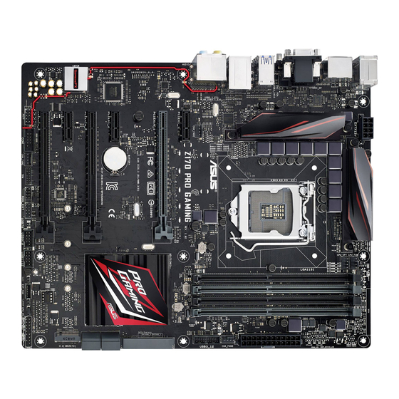
Одну из материнских плат Asus на чипсете Intel Z170 мы уже рассмотрели, а этой статьей мы продолжим обзор новинок и рассмотрим плату Asus Z170 Pro Gaming, которая также основана на чипсете Intel Z170 и поддерживает только процессоры Intel Core 6-го поколения (Skylake-S). Эта модель хотя и не относится к игровой серии Asus ROG (Republic Of Gamers), но ориентирована, как это следует из названия, на игровые ПК.
Комплектация и упаковка
Поскольку плата Z170 Pro Gaming не относится к элитной серии Asus, комплект ее поставки довольно скромный.
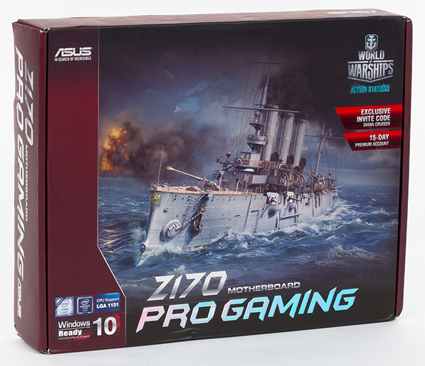
Она поставляется в достаточно компактной коробке, на которой рекламируется игра World of Warships. Причем это не просто реклама: купив данную плату и зарегистрировав ее, пользователь получает премиум-аккаунт на 15 дней в игре World of Warships и уникальный корабль.
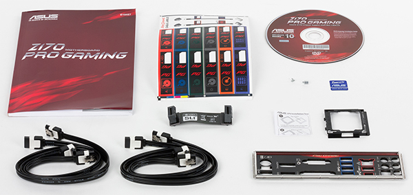
В комплект поставки входит инструкция пользователя (только на английском языке), DVD-диск с программным обеспечением и драйверами, четыре SATA-кабеля (все разъемы с защелками, два кабеля имеют угловой разъем с одной стороны), мостик SLI на две видеокарты и заглушка для задней панели платы.
Кроме того, имеется специальная пластиковая монтажная рамка, которая предназначена для безопасной установки процессора в разъем. Конечно, установить процессор можно и без нее, «классическим способом», однако с этой рамкой обеспечивается гарантия того, что контакты в процессорном разъеме не будут повреждены.
Конфигурация и особенности платы
Сводная таблица характеристик платы Asus Z170 Pro Gaming приведена ниже, а далее по тексту мы рассмотрим все ее особенности и функциональные возможности.
| Поддерживаемые процессоры |
Skylake-S |
| Процессорный разъем |
LGA1151 |
| Чипсет |
Intel Z170 |
| Память |
4 × DDR4 |
| Аудиоподсистема |
Realtek ALC1150 |
| Сетевой контроллер |
Intel i219-V |
| Слоты расширения |
2 × PCI Express 3.0 x16 (режим работы x16/x8) |
| SATA-разъемы |
6× SATA 6 Гбит/с (включая два порта разъема SATA Express) |
| USB-порты |
6 × USB 3.0 |
| Разъемы на задней панели |
4 × USB 3.0 |
| Внутренние разъемы |
24-контактный разъем питания ATX |
| Форм-фактор |
ATX (305×244 мм) |
| Средняя цена |
T-12793080 |
| Розничные предложения | L-12793080-10 |
Форм-фактор
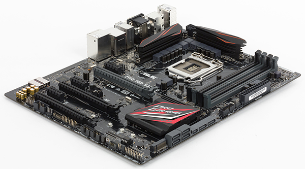
Плата Asus Z170 Pro Gaming выполнена в форм-факторе ATX (305×244 мм), и для ее монтажа в корпус предусмотрены девять стандартных отверстий.
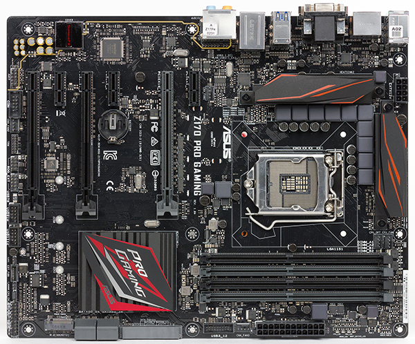
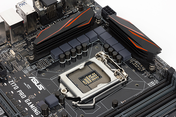
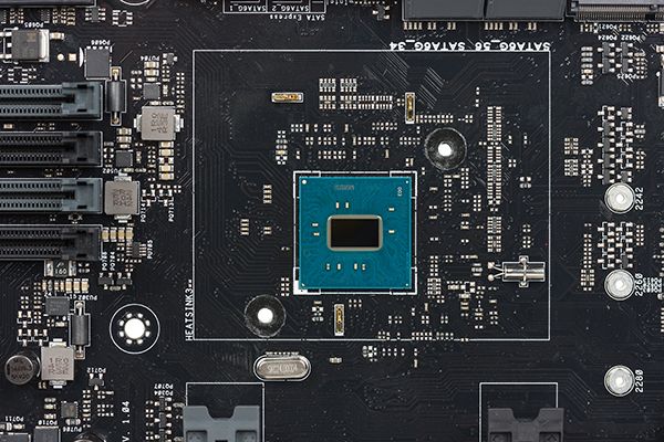
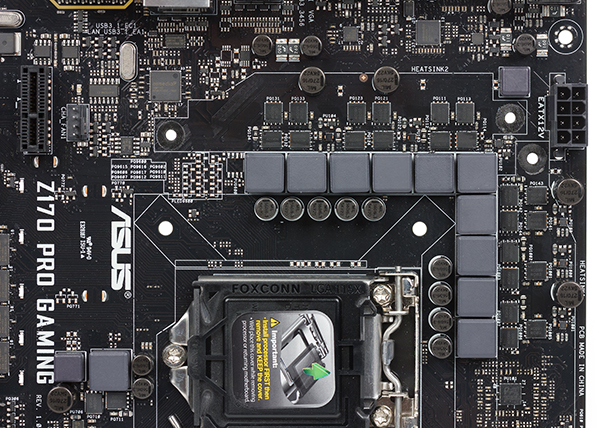
Чипсет и процессорный разъем
Плата Asus Z170 Pro Gaming основана на новом чипсете Intel Z170 и поддерживает только процессоры Intel Core 6-го поколения (кодовое наименованием Skylake-S) с разъемом LGA1151.
Память
Для установки модулей памяти на плате Asus Z170 Pro Gaming предусмотрено четыре DIMM-слота. В руководстве пользователя отмечается, что плата поддерживает небуферизованную память DDR4 (non-EСС), а максимальный объем памяти составляет 64 ГБ (при использовании модулей емкостью по 16 ГБ).
Слоты расширения
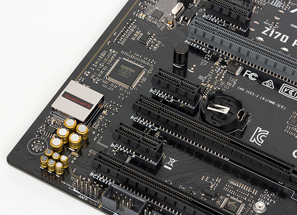
Для установки видеокарт или плат расширения на материнской плате Asus Z170 Pro Gaming имеется три слота с форм-фактором PCI Express x16, три слота PCI Express 3.0 x1 и разъем M.2, который позволяет устанавливать накопители типоразмера 2242/2260/2280/22110.

Два первых (от процессорного разъема) слота с форм-фактором PCI Express x16 реализованы с использованием 16 линий PCIe 3.0 процессора Skylake-S, которые, с применением мультиплексоров/демультиплексоров, группируются либо в один порт PCI Express 3.0 x16, либо в два порта PCI Express 3.0 x8. То есть если задействуется только один слот с форм-фактором PCI Express 3.0 x16 (ближайший к процессорному разъему), то он будет работать на скорости x16, а если одновременно оба слота, то они будут функционировать на скорости x8.
Еще один слот с форм-фактором PCI Express x16 реализован на базе четырех линий PCI Express 3.0 чипсета Intel Z170. Фактически, это слот PCI Express 3.0 x4, но в форм-факторе PCI Express x16.
Отметим, что плата Asus Z170 Pro Gaming поддерживает технологии Nvidia SLI и AMD CrossFireX и допускает установку двух видеокарт Nvidia и до трех видеокарт AMD.
Три слота PCI Express 3.0 x1 (с закрытыми концами) реализованы через чипсет Intel Z170.
Разъем M.2 поддерживает устройства PCIe и SATA. Для его реализации используется четыре чипсетных порта PCI Express 3.0 или два порта SATA 6 Гбит/с, что обеспечивает пропускную способность в 32 ГТ/с (при подключении PCIe-устройств).
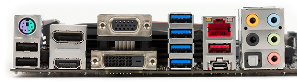
Видеоразъемы
Поскольку процессоры Skylake-S имеют интегрированное графическое ядро, для подключения монитора на задней панели платы имеется видеовыход DisplayPort 1.2 (максимальное разрешение 4096×2304@60 Гц), HDMI 1.4 (4096×2160@24 Гц), DVI (1920×1200@60 Гц) и VGA (1920×1200@60 Гц). К плате можно одновременно подключить три монитора.
По поводу видеовыхода VGA (разъем D-Sub) напомним, что в процессоре Skylake-S более нет шины FDI для соединения с чипсетом, и видеовыход VGA реализуется путем дополнительного преобразования цифрового видеовыхода в аналоговый.
SATA-порты, разъем SATA Express
Для подключения накопителей или оптических приводов на плате предусмотрено в совокупности шесть портов SATA 6 Гбит/с. Это четыре отдельных порта SATA 6 Гбит/с и еще два порта SATA 6 Гбит/с в составе разъема SATA Express.
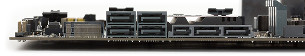
Четыре отдельных порта SATA 6 Гбит/с и два порта в составе разъема SATA Express реализованы на базе интегрированного в чипсет Intel Z170 контроллера. Эти порты поддерживают возможность создания RAID-массивов уровней 0, 1, 5, 10.
Отметим также, что возможность создания RAID-массива предусмотрена также и для PCIe устройств, одно из которых подключается к разъему M.2 (PCIe 3.0 x4), а второе устанавливается в слот PCI Express 3.0 x4.
USB-разъемы
Для подключения всевозможных периферийных устройств на плате предусмотрено шесть портов USB 3.0, восемь портов USB 2.0 и два порта USB 3.1.
Шесть портов USB 3.0 и восемь портов USB 2.0 реализованы на базе чипсета Intel Z170 (напомним, что чипсет поддерживает до 14 портов USB, из которых до 10 портов могут быть USB 3.0). Четыре порта USB 3.0 и два порта USB 2.0 вынесены на заднюю панель платы, а для подключения еще двух портов USB 3.0 и шести портов USB 2.0 на плате предусмотрено один разъем USB 3.0 и три разъема USB 2.0.
Для реализации двух портов USB 3.1 на плате используется двухпортовый контроллер ASMedia ASM1142. Причем этот контроллер подключен к чипсету двумя линиями PCIe 3.0 — в чем преимущество такого способа подключения, мы уже писали в статье, посвященной плате Asus Z170-Deluxe.
Отметим, что оба порта USB 3.1 выведены на заднюю панель платы. Один порт имеет обычный разъем Type A, а другой порт имеет симметричный разъем Type C.
Сетевой интерфейс
Для подключения к сети на плате Asus Z170 Pro Gaming имеется гигабитный сетевой интерфейс на базе PHY-контроллера (контроллер физического уровня) Intel i219-V (используется контроллер MAC-уровня, интегрированный в чипсет). Этот контроллер задействуют для подключения чипсетный порт PCIe.
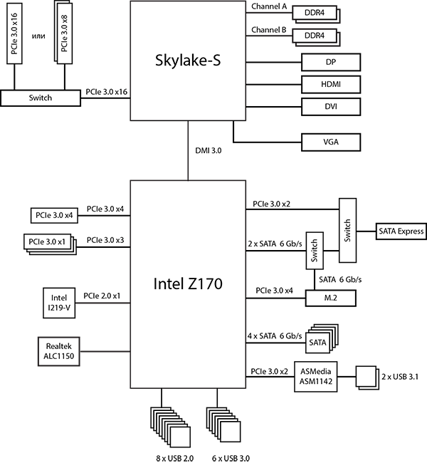
Как это работает
Прежде всего напомним, что чипсет Intel Z170 имеет 26 высокоскоростных портов ввода/вывода, в качестве которых могут быть порты PCIe 3.0, USB 3.0 и SATA 6 Гбит/с. Часть высокоскоростных портов ввода/вывода строго закреплена за портами USB 3.0, еще часть портов может выступать только в качестве портов PCIe 3.0, но есть и порты двойного назначения, которые можно конфигурировать либо как порты PCIe 3.0, либо как порты SATA 6 Гбит/с, а есть и порты, которые конфигурируются либо как порты PCIe 3.0, либо как порты USB 3.0. С учетом портов двойного назначения, под порты USB 3.0 отводится 10 чипсетных высокоскоростных портов ввода/вывода, под порты SATA 6 Гбит/с — 6 портов, и под порты PCIe 3.0 — 20 портов. Есть и еще одно ограничение, которое заключается в том, что одновременно к 20 портам PCIe можно подключить не более 16 PCIe устройств (в качестве устройства может выступать контроллер, разъем или слот). Естественно, что для подключения одного PCIe устройства может потребоваться и долее одного порта PCIe (например, 2 или 4).
Ну а теперь вернемся к плате Asus Z170 Pro Gaming.
Как мы уже отмечали, на ней реализовано шесть чипсетных портов USB 3.0, четыре отдельных чипсетных порта SATA 6 Гбит/с, а также два порта SATA 6 Гбит/с в составе разъема SATA Express. Кроме того, еще один порт SATA 6 Гбит/с требуется под разъем M.2, который поддерживает SATA устройства. То есть, с учетом возможностей чипсета Intel Z170 SATA-портов не хватает.
Также имеется контроллер ASMedia ASM1142 под который требуется два порта PCIe 3.0, разъем M.2, под который требуется еще четыре порта PCIe 3.0, разъем SATA Express — это еще два порта PCIe 3.0. Добавим к этому сетевой контроллер, под которые требуется еще один порта PCIe, а также учтем наличие слота PCI Express 3.0 x4 и трех слотов PCI Express 3.0 x1. В результате получаем, что требуется 16 портов PCIe 3.0, то есть даже меньше того количества, которое обеспечивает чипсет. Ну а кажущаяся нехватка чипсетных портов SATA 6 Гбит/с и решается в данном случае очень просто. Разъем M.2 и SATA Express выполнены разделяемыми по SATA портам, то есть в совокупности для разъемов M.2 и SATA Express требуется лишь два порта SATA 6 Гбит/с.
Если же посчитать общее количество реализованных чипсетных высокоскоростных портов ввода вывода, то их окажется не более 26 в зависимости от того, какие устройства подключены к разъемам M.2 и SATA Express. Это шесть фиксированных портов USB 3.0, четыре фиксированных порта SATA 6 Гбит/с и десять фиксированных портов PCIe 3.0 (слоты, сетевой контроллер и контроллер USB 3.1). Далее, если к разъемам M.2 и SATA Express подключены PCIe устройства, то получаем еще шесть портов PCIe 3.0, ну а если к одному из этих разъемов подключено SATA-устройство, то получаем еще два порта SATA 6 Гбит/с и два или четыре порта PCIe 3.0.
Блок-схема платы Asus Z170 Pro Gaming показана на рисунке.
Дополнительные особенности
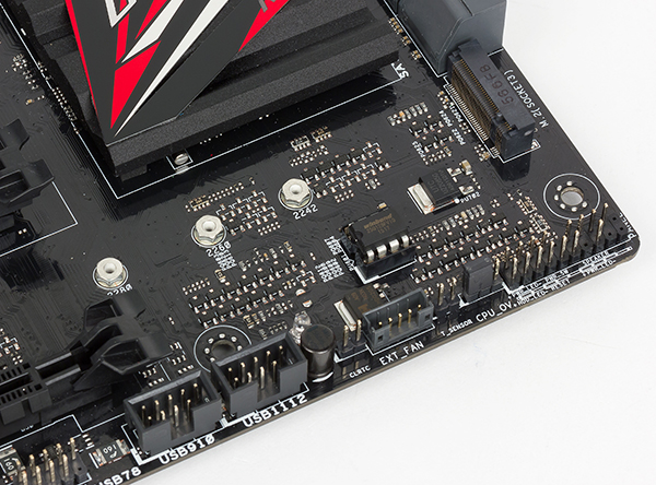
Никаких дополнительных «фишек» на плате Asus Z170 Pro Gaming не реализовано. Нет тут ни отдельных кнопок включения и перезагрузки, ни индикатора POST-кодов и пр.
Имеется лишь два переключателя (перемычки): Clear CMOS (для сброса настроек BIOS) и CPU Over Voltage (предназначен для разгона процессора и позволяет увеличивать напряжение на процессоре в более широких пределах).
Также, пожалуй, стоит отметить наличие специального разъема ROG Extension, который предназначен для подключения панели Asus Front Base, приобретаемой отдельно.
Система питания
Как и большинство плат, модель Asus Z170 Pro Gaming имеет 24-контактный и 8-контактный разъемы для подключения блока питания.
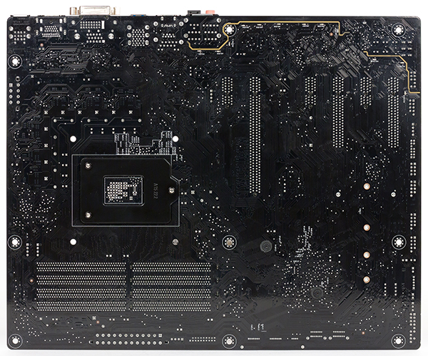
Регулятор напряжения питания процессора на плате является 10-канальным и основан на PWM-контроллере Digi+ VRM c маркировкой ASP1400. Cами каналы питания построены с использованием дискретных MOSFET-транзисторов NTMFS4C09N (максимальный ток 52 А) компании On Semiconductor и драйверов International Rectifier IR3598, которые расположены с обратной стороны платы.
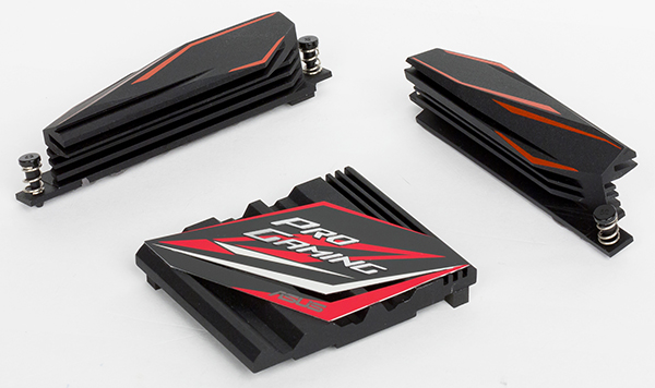
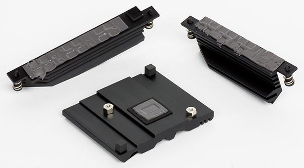
Система охлаждения
Для охлаждения различных тепловыделяющих компонентов, на плате Asus Z170 Pro Gaming предусмотрено в совокупности три радиатора. Один из них установлен на чипсете, а еще два расположены с двух сторон от процессорного разъема и закрывают MOSFET-транзисторы регулятора напряжения питания процессора.
Помимо этого, для создания эффективной системы теплоотвода на плате предусмотрено пять четырехконтактных разъемов для подключения вентиляторов. Традиционно, скорость любого корпусного вентилятора, вентилятора кулера процессора и вентилятора системы водяного охлаждения можно настраивать либо через UEFI BIOS, либо через утилиту Fan Xpert 3.
Аудиоподсистема
На плате Asus Z170 Pro Gaming аудиоподсистема основана на аудиокодеке Realtek ALC1150. Все элементы аудиотракта изолированы на уровне слоев PCB от прочих компонентов платы и выделены в отдельную зону.
Для тестирования выходного звукового тракта, предназначенного для подключения наушников или внешней акустики, мы использовали внешнюю звуковую карту Creative E-MU 0204 USB в сочетании с утилитой Right Mark Audio Analyzer 6.3.0. Тестирование проводилось для режима стерео, 24-бит/44,1 кГц. По результатам тестирования аудиотракт на плате Asus Z170 Pro Gaming получил оценку «Очень хорошо».
Полный отчет с результатами тестирования в программе RMAA 6.3.0 вынесен на отдельную страницу, далее приведен краткий отчет.
| Неравномерность АЧХ (в диапазоне 40 Гц — 15 кГц), дБ |
+0,01, −0,08 |
Отлично |
| Уровень шума, дБ (А) |
−80,2 |
Хорошо |
| Динамический диапазон, дБ (А) |
80,8 |
Хорошо |
| Гармонические искажения, % |
0,0049 |
Очень хорошо |
| Гармонические искажения + шум, дБ (A) |
−73,7 |
Посредственно |
| Интермодуляционные искажения + шум, % |
0,022 |
Хорошо |
| Взаимопроникновение каналов, дБ |
−78,7 |
Очень хорошо |
| Интермодуляции на 10 кГц, % |
0,020 |
Хорошо |
| Общая оценка |
Очень хорошо |
UEFI BIOS
UEFI BIOS здесь по интерфейсу и возможностям очень похож на UEFI BIOS, который используется на плате Asus Z170-Deluxe. Правда, используется другая цветовая гамма интерфейса (черно-красная), но это, конечно же, не принципиально.
Итак, начнем с того, что, как и на всех платах Asus, на плате Asus Z170 Pro Gaming имеется возможность очень просто обновить версию UEFI BIOS, используя для этого традиционную утилиту Asus EZ Flash, встроенную в BIOS. Теперь используется новая версия этой утилиты Asus EZ Flash 3, которая позволяет обновлять UEFI BIOS не только с флэш-накопителя, но и через интернет.
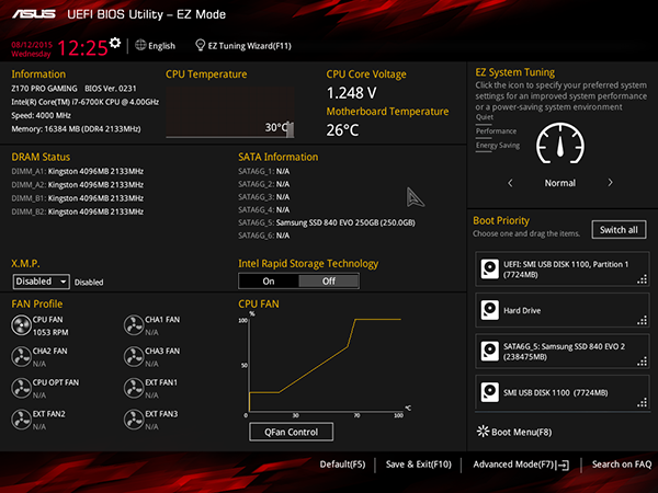
Традиционно UEFI BIOS на платах Asus имеет два режима отображения: простой (EZ Mode) и расширенный (Advanced Mode). В новом интерфейсе UEFI BIOS все осталось без изменений: те же два режима отображения и те же самые вкладки настроек.
Режим EZ Mode предназначен для базовой конфигурации платы и контроля основных параметров, а тонкая настройка платы и разгон системы доступны только в режиме Advanced Mode.
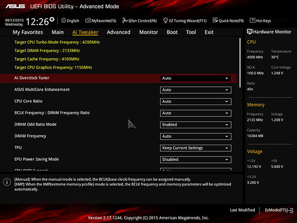
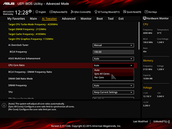
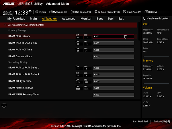
Для разгона процессора и памяти предназначена традиционная вкладка AI Tweaker, на которой предусмотрены все возможные опции для разгона.
И точно также, как и на всех платах Asus, разгон разблокированного процессора (K-серии) возможен только в случае, когда активирован режим Turbo Mode (он активирован по умолчанию). Активирование данного режима производится на вкладке Advanced в меню CPU Power ConfigurationCPU Power Management Configuration.
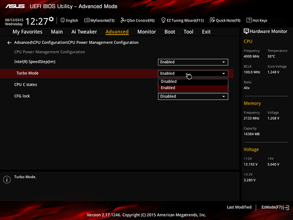
Если же заблокировать режим Turbo Mode, то несмотря на возможность изменения коэффициента умножения процессора, он будет работать на номинальной частоте.
Кроме того, для разгона процессора на плате Asus Z170 Pro Gaming (как, кстати, и на других платах Asus) на вкладке Ai Tweaker для параметра Ai Overclock Tuner нужно установить значение Manual или XMP.
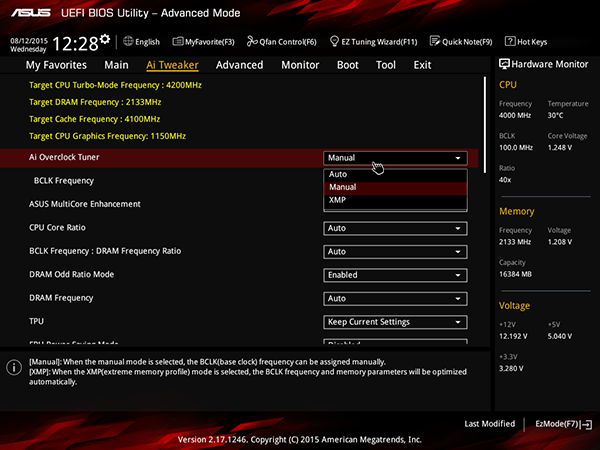
В этом случае имеется возможность менять частоту тактового генератора BCLK и коэффициент умножения ядер процессора. Можно задавать коэффициент умножения для каждого случая числа загруженных ядер процессора, а можно задавать коэффициент умножения одновременно для всех загруженных ядер процессора.
Частоту BCLK можно менять с шагом в 1 МГц в диапазоне от 50 до 650 МГц.
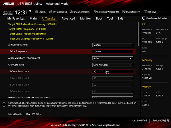
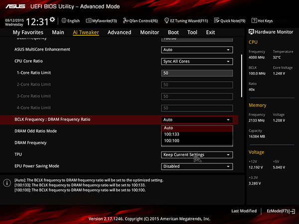
Кроме коэффициента умножения ядер процессора (CPU Core Ratio) и частоты BCLK (BCLK Frequency), в настройках AI Tweaker можно задавать коэффициент BCLK Frequency : DRAM Frequency (100:100, 100:133) и настроить работу модулей памяти.
При частоте BCLK 100 МГц максимальная частота модулей памяти DDR4 может составлять 4266 МГц.
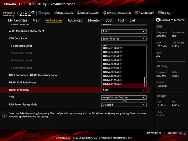
Естественно, предусмотрена возможность настройки таймингов памяти.
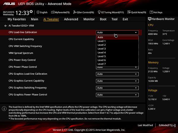
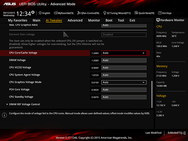
Ну и кроме того, можно настроить напряжение питания процессора, памяти и т.д., а также настроить режим работы регулятора напряжения питания.
Еще одной особенностью UEFI BIOS платы Asus Z170 Pro Gaming является возможность настройки скоростных режимов всех вентиляторов, подключенных к плате. Кроме выбора одного из трех предустановленных скоростных режимов (Standard, Silent, Turbo и Full Speed), можно настроить скоростной режим вручную. При ручной настройке скорости вращения вентилятора на процессоре имеется возможность задать график изменения скорости вращения вентиляторов от температуры процессора по трем точкам. Для каждой точки на графике задаются координаты (температура, скорость вращения). Причем скорость вращения вентилятора меняется в диапазоне от 20 до 100% для вентилятора кулера процессора и от 60 до 100% для дополнительных корпусных вентиляторов. Допустимый интервал изменения температуры составляет 0 до 75 °C.

Фирменные утилиты
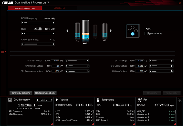
Традиционно, как и к любой плате Asus, к модели Asus Z170 Pro Gaming большой комплект фирменных утилит. Часть утилит объединены в единый пакет AI Suite 3, который и представляет наибольший интерес. В данный пакет входят такие утилиты, как Dual Intelligent Processors 5, TPU, TurboApp, EPU, FanXpert 3, DIGI+VRM, PC Cleaner, Ai Charger+, USB 3.1 Boost, EZ Update, Mobo Connect, Push Notice и LED Control.
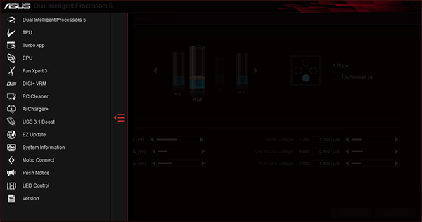
Большинство из этих утилит знакомы по предыдущим версиям пакета AI Suite. Так, утилиты TPU и DIGI+VRM предназначены для разгона процессора и настройки режима работы регулятора напряжения питания; утилита FanXpert 3 позволяет настраивать скоростной режим работы всех вентиляторов, а утилита USB 3.1 Boost предназначена для увеличения скорости передачи по протоколу USB 3.0/3.1.
Выводы
В целом, плата Asus Z170 Pro Gaming производит очень хорошее впечатление. Это не топовый продукт, и в нем нет излишних «наворотов». Зато функциональные возможности чипсета реализованы в полной мере, а из дополнительных контроллеров присутствует лишь действительно актуальный ASMedia ASM1142 для реализации двух портов USB 3.1. Единственный спорный момент — наличие видеоразъема VGA: напомним, что он реализован не через чипсет, а путем дополнительного преобразования цифрового сигнала в аналоговый. Это, конечно, не сильно удорожает плату, но не очень понятно, зачем нужен этот устаревший видеоразъем.
Плата Asus Z170 Pro Gaming вполне подойдет и для создания производительных компьютеров с широкими функциональными возможностями, и для сборки мощных игровых ПК. Кроме того, она реализует отличные возможности для разгона системы. Стоимость платы на момент анонса статьи представляла собой разумный компромисс между ценой самых бюджетных решений на новом чипсете и топовых моделей, в том числе и самой Asus.
Эта модель на сайте производителя
Плата предоставлена на тестирование производителем
PCIEX16_1
Model name LED
PCIEX16_2
PCIEX16_3
PCIEX1_2
PCIEX1_3
PCIEX1_1
M.2(SOCKET3)
Intel
I219V
ASM
1442K
ASM
1142
USB1112
USB910
AAFP
EATXPWR
BATTERY
Super
I/O
SupremeFX LED
ALC
1150
TPU
KBMS
_USB1314
DVI
HDMI
DP
VGA
T_SENSOR
CLRTC
EXT_FAN
CPU_OV
24.4cm(9.6in)
DDR4 DIMM_A1 (64bit, 288-pin module)
DDR4 DIMM_A2 (64bit, 288-pin module)
DDR4 DIMM_B1 (64bit, 288-pin module)
DDR4 DIMM_B2 (64bit, 288-pin module)
SATA6G_34
SATA6G_56
SATAEXPRESS
SATA6G_1
SATA6G_2
LAN_USB3.1_EA1
USB3.1_EC1
USB3_3456
CHA_FAN1
CHA_FAN3
CHA_FAN2
CPU_FAN
CPU_OPT
30.5cm(12in)
LGA1151
DIGI
+VRM
COM
EATX12V
USB3_12
Intel
®
Z170
TPM
ROG_EXT
128Mb
BIOS
PANEL
SB_PWR
AUDIO
USB78
Z170 PRO GAMING
Quick Start Guide
Кратко упътване за бърз старт
Stručná příručka
Quick Start-vejledning
Snelstartgids
Lühijuhend
Guide de démarrage rapide
Pikakäynnistysopas
Schnellstarthilfe
Οδηγός γρήγορης έναρξης
Beüzemelési útmutató
Guida Rapida
Panduan Ringkas
クイックスタートガイド
Жылдам іске қосу нұсқаулығы
빠른 시작 설명서
Greitos darbo pradžios vadovas
Īsa pamācība
Hurtigstartsveiledning
Guia de consulta rápida
Instrukcja szybkiej instalacji
Краткое руководство
Ghid de pornire rapidă
Guía de inicio rápida
Vodič za brzo korišćenje
Stručný návod na spustenie
Snabbstartsguide
คู่มือเริ่มต้นอย่างเร็ว
Hızlı Başlatma Kılavuzu
Höôùng daãn khôûi ñoäng nhanh
vodič za brzi početak rada
Motherboard Layout
15060-58730000
Q10457
First Edition
June 2015
Copyright © ASUSTeK Computer Inc.
All Rights Reserved
Install the CPU
Инсталирайте процесора
Instalace procesoru
Installer CPU’en
De CPU installeren
Paigaldage CPU
Installer le CPU
Asenna suoritin
Installieren der CPU
Εγκατάσταση της CPU
Helyezze be a CPU-t
Installare la CPU
Pasang CPU
CPUを設置する
CPU 설치
Sumontuokite centrinį procesorių
Uzstādiet centrālo procesoru
Installer sentralprosessoren (CPU)
Instale a CPU
Instalacja procesora
Установка процессора
Instalaţi CPU-ul
Instalar la CPU
Instalirajte CPU
Inštalácia centrálneho procesora
Installera CPU
ติดตั้ง CPU
CPU’yu takın
Lắp CPU
Instalacija procesora
Step 1
Step 2
Install the CPU fan
Инсталирайте вентилатора на процесора
Instalace ventilátoru procesoru
Installer CPU-blæseren
De CPU-ventilator installeren
Paigaldage CPU ventilaator
Installer le ventilateur de CPU
Asenna suorittimen tuuletin
Installieren des CPU-Lüfters
Εγκατάσταση του ανεμιστήρα της CPU
Szerelje be a CPU ventillátort
Installare la ventola della CPU
Pasang kipas CPU
CPUファン を設置する
CPU 팬 설치
Sumontuokite centrinio procesoriaus ventiliatorių
Uzstādiet centrālā procesora ventilatoru
Installer CPU-viften
Instale a ventoinha de CPU
Instalacja wentylatora procesora
Установка вентилятора
Instalaţi ventilatorul CPU-ului
Instalar el ventilador de la CPU
Instalirajte CPU ventilator
Inštalácia ventilátora centrálneho procesora
Installera CPU-fläkten
ติดตั้งพัดลม CPU
CPU fanını takın
Lắp quạt CPU
Instalacija ventilatora procesora
Step 3
Install memory modules
Инсталирайте модулите памет
Instalace paměťových modulů
Installer hukommelsesmodulerne
Geheugenmodules installeren
Paigaldage mälumoodulid
Installer les modules mémoire
Asenna muistimoduulit
Installieren der Speichermodule
Εγκατάσταση των στοιχείων μνήμης
Helyezze be a memória modulokat
Installare i moduli di memoria
Pasang modul memori
メモリーモジュールを設置する
메모리 모듈 설치
Sumontuokite atminties modulius
Uzstādiet atmiņas moduļus
Installer minnemoduler
Instale módulos de memória
Instalacja modułów pamięci
Установка модулей памяти
Instalaţi modulele de memorie
Instalar los módulos de memoria
Instalirajte module memorije
Inštalácia pamäťových modulov
Installera minnesmoduler
ติดตั้งโมดูลหน่วยความจำา
Bellek modüllerini takın
Lắp các thanh nhớ
Instalacija memorijskih modula
Step 4
Install SATA devices
Инсталирайте SATA устройства
Instalace zařízení SATA
Installer SATA-udstyret
SATA-apparaten installeren
Paigaldage SATA seadmed
Installer des périphériques SATA
Asenna SATA-laitteet
Installieren der SATA-Geräte
Εγκατάσταση συσκευών SATA
Szerelje be a SATA eszközöket
Installare i dispositivi SATA
Pasang perangkat SATA
SATA デバイスを取り付ける
SATA 장치 설치
Sumontuokite SATA įrenginius
Uzstādiet SATA ierīces
Installer SATA-enheter
Instale dispositivos SATA
Instalacja urządzeń SATA
Установка SATA устройств
Instalaţi dispozitivele SATA
Instalar dispositivos SATA
Instalirajte SATA uređaje
Inštalácia zariadení SATA
Installera SATA-enheter
ติดตั้งอุปกรณ์ SATA
SATA aygıtlarını takın
Lắp các thiết bị SATA
Instalacija SATA uređaja
1
1
2
2
B
A
Step 1
Step 5
Step 3
Step 6
Step 2
Step 7
Step 7
Step 4
Australia statement notice
From 1 January 2012 updated warranties apply to all ASUS products, consistent with
the Australian Consumer Law. For the latest product warranty details please visit http://
support.asus.com. Our goods come with guarantees that cannot be excluded under
the Australian Consumer Law. You are entitled to a replacement or refund for a major
failure and compensation for any other reasonably foreseeable loss or damage. You are
also entitled to have the goods repaired or replaced if the goods fail to be of acceptable
quality and the failure does not amount to a major failure.
If you require assistance please call ASUS Customer Service 1300 2787 88 or visit us at
http://support.asus.com
India E-waste (Management and handling) Rule 2011
This product complies with the «India E-waste (Management and Handling)Rule 2011»
and prohibits use of lead, mercury, hexavalent chromium, polybrominated biphe-
nyls(PBBs) and polybrominated diphenyl ethers (PBDEs) in concentrations exceeding
0.1 % by weight in homogenous materials and 0.01 % by weight in homogenous materi-
als for cadmium, except for the exemptions listed in Schedule-II of the Rule
AEEE Yönetmeliğine Uygundur
1
2
A
B
C
3
1
2
3
1
3
2
F
D
E
-
Драйверы
32
-
Инструкции по эксплуатации
4
Языки:

ASUS Z170 PRO GAMING инструкция по эксплуатации
(6 страниц)
- Языки:Английский
-
Тип:
PDF -
Размер:
1.26 MB -
Описание:
Win7 Installation guide(English)
Просмотр

ASUS Z170 PRO GAMING инструкция по эксплуатации
(96 страниц)
- Языки:Японский
-
Тип:
PDF -
Размер:
4.7 MB -
Описание:
Z170 PRO GAMING User’s manual (Japanese)
Z170 PRO GAMING User’s manual (Japanese)
Просмотр

ASUS Z170 PRO GAMING инструкция по эксплуатации
(100 страниц)
- Языки:Французский
-
Тип:
PDF -
Размер:
6.66 MB -
Описание:
Z170 PRO GAMING User’s manual (French)
Z170 PRO GAMING User’s manual (French)
Просмотр

ASUS Z170 PRO GAMING инструкция по эксплуатации
(100 страниц)
- Языки:Немецкий
-
Тип:
PDF -
Размер:
5.26 MB -
Описание:
Z170 PRO GAMING User’s manual (German)
Z170 PRO GAMING User’s manual (German)
Просмотр
На NoDevice можно скачать инструкцию по эксплуатации для ASUS Z170 PRO GAMING. Руководство пользователя необходимо для ознакомления с правилами установки и эксплуатации ASUS Z170 PRO GAMING. Инструкции по использованию помогут правильно настроить ASUS Z170 PRO GAMING, исправить ошибки и выявить неполадки.