- Manuals
- Brands
- Asus Manuals
- Motherboard
- TUF Gaming X570-Plus
- Manual
-
Contents
-
Table of Contents
-
Bookmarks
Quick Links
Related Manuals for Asus TUF Gaming X570-Plus
Summary of Contents for Asus TUF Gaming X570-Plus
-
Page 1
TUF GAMING X570-PLUS… -
Page 2
Product warranty or service will not be extended if: (1) the product is repaired, modified or altered, unless such repair, modification of alteration is authorized in writing by ASUS; or (2) the serial number of the product is defaced or missing. -
Page 3: Table Of Contents
Contents Safety information ………………….. v About this guide ………………….vi TUF GAMING X570-PLUS specifications summary ……….viii Package contents …………………. xii Installation tools and components …………….. xiii Chapter 1: Product Introduction Motherboard overview …………….1-1 1.1.1 Before you proceed …………..1-1 1.1.2…
-
Page 4
3.6.11 Network Stack Configuration…………. 3-15 Monitor menu ………………. 3-16 Boot menu ………………..3-16 Tool menu ………………..3-17 3.9.1 ASUS EZ Flash 3 Utility …………3-17 3.9.2 ASUS User Profile…………..3-18 3.9.3 ASUS SPD Information …………. 3-18 3.9.4 ASUS Armoury Crate …………..3-18 3.10… -
Page 5: Safety Information
Safety information Electrical safety • To prevent electrical shock hazards, disconnect the power cable from the electrical outlet before relocating the system. • When adding or removing devices to or from the system, ensure that the power cables for the devices are unplugged before the signal cables are connected. If possible, disconnect all power cables from the existing system before you add a device.
-
Page 6: About This Guide
Refer to the following sources for additional information and for product and software updates. ASUS website The ASUS website (www.asus.com) provides updated information on ASUS hardware and software products. Optional documentation Your product package may include optional documentation, such as warranty flyers, that may have been added by your dealer.
-
Page 7
Conventions used in this guide To ensure that you perform certain tasks properly, take note of the following symbols used throughout this manual. DANGER/WARNING: Information to prevent injury to yourself when trying to complete a task. CAUTION: Information to prevent damage to the components when trying to complete a task. -
Page 8: Tuf Gaming X570-Plus Specifications Summary
AMD Ryzen™ with Radeon™ Vega Graphics Processors Supports up to 16 cores* * Due to the CPU limitations, CPU cores supported vary by processor. ** Refer to www.asus.com for the AMD CPU support list. Chipset AMD X570 Chipset AMD Ryzen™ 3 Generation Processors — 4 x DIMM, max.
-
Page 9
— 4 x USB 2.0 ports at mid-board ASUS TUF PROTECTION — ASUS SafeSlot — Protect your graphics card Investment — ASUS ESD Guard: Enhanced ESD protection — ASUS LANGuard: Protects against LAN surges, lightning strikes and static-electricity discharges! -
Page 10
TUF GAMING X570-PLUS specifications summary ASUS Exclusive Features — ASUS Ai Charger — ASUS AI Suite 3 ASUS EZ DIY — ASUS UEFI BIOS EZ Mode ASUS Unique Features — ASUS CrashFree BIOS 3 — ASUS EZ Flash 3 ASUS Q-Design… -
Page 11
TUF GAMING X570-PLUS specifications summary 256Mb Flash ROM, UEFI AMI BIOS, PnP, SM BIOS 3.2, ACPI 6.2, Multi-language BIOS, ASUS EZ Flash 3, CrashFree BIOS 3, F6 BIOS Qfan Control, F3 My Favorites, F4 AURA ON/OFF, Last Modified log, F9 Search, F12 PrintScreen, and ASUS DRAM SPD (Serial… -
Page 12: Package Contents
Package contents Check your motherboard package for the following items. Motherboard TUF GAMING X570-PLUS Cables 2 x SATA 6 Gb/s cables 1 x I/O shield 1 x M.2 screw package Accessories 1 x TUF Gaming Sticker 1 x TUF Certification card…
-
Page 13: Installation Tools And Components
Installation tools and components 1 Bag of screws Phillips (cross) screwdriver PC chassis Power supply unit AMD AM4 CPU AMD AM4/AM3 compatible CPU Fan DDR4 DIMM SATA hard disk drive SATA optical disc drive (optional) Graphics card (optional) The tools and components in the table above are not included in the motherboard package. xiii…
-
Page 15: Chapter 1: Product Introduction
Before you install or remove any component, ensure that the ATX power supply is switched off or the power cord is detached from the power supply. Failure to do so may cause severe damage to the motherboard, peripherals, or components. ASUS TUF GAMING X570-PLUS…
-
Page 16: Motherboard Layout
1.1.2 Motherboard layout 24.4cm(9.6in) RGB_HEADER1 CPU_FAN CPU_OPT KBMS EATX12V_2 EATX12V_1 _U32G1_56 BOOT_DEVICE_LED DIGI VGA_LED +VRM CPU_LED DRAM_LED U32G2 U32G1_34 HDMI_DP LAN_U32G2_12 AUDIO SPI_TPM 22110 2280 2260 2242 PCIEX16_1 ® Realtek L8200A ® X570 BATTERY PCIEX1_1 Super PCIEX16_2 M.2_2(SOCKET3) PCIEX1_2 22110 2280 2260 2242…
-
Page 17
12. Clear RTC RAM jumper (2-pin CLRTC) 13. System panel connectors (20-5 pin PANEL) 1-13 14. USB 2.0 connectors (10-1 pin USB78, USB910) 1-12 15. Serial port connector (10-1 pin COM) 1-15 16. Front panel audio connector (10-1 pin AAFP) 1-10 ASUS TUF GAMING X570-PLUS… -
Page 18: Central Processing Unit (Cpu)
(DIMM) slots. A DDR4 module is notched differently from a DDR, DDR2, or DDR3 module. DO NOT install a DDR, DDR2, or DDR3 memory module to the DDR4 slot. TUF GAMING X570-PLUS 288-pin DDR4 DIMM sockets Chapter 1: Product Introduction…
-
Page 19
Always install the DIMMS with the same CAS Latency. For an optimum compatibility, we recommend that you install memory modules of the same version or data code (D/C) from the same vendor. Check with the vendor to get the correct memory modules. ASUS TUF GAMING X570-PLUS… -
Page 20: Expansion Slots
1.1.5 Expansion slots Unplug the power cord before adding or removing expansion cards. Failure to do so may cause you physical injury and damage motherboard components. PCIEX16_1 PCIEX1_1 PCIEX16_2 PCIEX1_2 PCIEX1_3 Slot No. Slot Description PCIe 4.0/3.0 x16_1 slot PCIe 4.0 x1_1 slot PCIe 4.0 x16_2 slot PCIe 4.0 x1_2 slot PCIe 4.0 x1_3 slot…
-
Page 21
Single VGA/PCIe card Dual VGA/PCIe card • We recommend that you provide sufficient power when running CrossFireX™ mode. • Connect chassis fans to the motherboard chassis fan connectors when using multiple graphics cards for better thermal environment. ASUS TUF GAMING X570-PLUS… -
Page 22: Onboard Leds
VGA (WHITE) CPU (RED) DRAM (YELLOW) TUF GAMING X570-PLUS CPU/ DRAM/ BOOT_DEVICE/ VGA LED The Q LEDs provide the most probable cause of an error code as a starting point for troubleshooting. The actual cause may vary from case to case.
-
Page 23: Jumpers
CLRTC PIN 1 TUF GAMING X570-PLUS Clear RTC RAM To erase the RTC RAM: Turn OFF the computer and unplug the power cord. Use a metal object such as a screwdriver to short the two pins.
-
Page 24: Internal Connectors
Audio. Connect one end of the front panel audio I/O module cable to this connector. AAFP HD-audio-compliant pin definition TUF GAMING X570-PLUS Front panel connector We recommend that you connect a high-definition front panel audio module to this connector to avail of the motherboard’s high-definition audio capability. SPI_TPM connector (14-1 pin SPI_TPM)
-
Page 25
SATA6G_8 SATA6G_5 SATA6G_6 TUF GAMING X570-PLUS SATA 6 Gb/s connectors • These connectors are set to [AHCI] by default. If you intend to create a Serial ATA RAID set using these connectors, set the SATA Mode Selection item in the BIOS to [RAID]. -
Page 26
IntA_P2_D- IntA_P1_D+ IntA_P2_D+ TUF GAMING X570-PLUS USB 3.2 Gen 1 connector The USB 3.2 Gen 1 module is purchased separately. The plugged USB 3.2 Gen 1 device may run on xHCI or EHCI mode depending on the operating system’s setting. -
Page 27
+HDD_LED- RESET +PWR_LED- * Requires an ATX power supply TUF GAMING X570-PLUS System panel connector • System power LED (2-pin or 3-1 pin PLED) The 2-pin or 3-1 pin connector is for the system power LED. Connect the chassis power LED cable to this connector. The system power LED lights up when you turn on the system power, and blinks when the system is in sleep mode. -
Page 28
AIO PUMP PWM AIO PUMP IN AIO PUMP PWR TUF GAMING X570-PLUS Fan connectors • DO NOT forget to connect the fan cables to the fan connectors. Insufficient air flow inside the system may damage the motherboard components. These are not jumpers! Do not place jumper caps on the fan connectors! •… -
Page 29
This connector is for a serial (COM) port. Connect the serial port module cable to this connector, then install the module to a slot opening at the back of the system chassis. PIN 1 TUF GAMING X570-PLUS Serial port (COM) connector The COM module is purchased separately. ASUS TUF GAMING X570-PLUS… -
Page 30
22110 2280 2260 2242 TUF GAMING X570-PLUS M.2 sockets • For AMD Ryzen™ 3 Generation Processors, the M.2_1 socket supports PCIe 4.0 x4 mode and SATA mode M Key design and type 2242 / 2260 / 2280 / 22110 storage devices. -
Page 31
RGB_HEADER2 PIN 1 +12V G R B TUF GAMING X570-PLUS RGB Header The RGB header supports 5050 RGB multi-color LED strips (12V/G/R/B), with a maximum power rating of 3A (12V), and no longer than 3 m. Before you install or remove any component, ensure that the ATX power supply is switched off or the power cord is detached from the power supply. -
Page 32
PIN 1 Data Ground TUF GAMING X570-PLUS ADD header The addressable gen 2 RGB header supports WS2812B addressable RGB LED strips (5V/ Data/Ground), with a maximum power rating of 3A (5V) and a maximum of 120 LEDs Before you install or remove any component, ensure that the ATX power supply is switched off or the power cord is detached from the power supply. -
Page 33: Chapter 2: Basic Installation
2.1.1 Motherboard installation Install the ASUS I/O Shield to the chassis rear I/O panel. Place the motherboard into the chassis, ensuring that its rear I/O ports are aligned to the chassis’ rear I/O panel.
-
Page 34
Place nine (9) screws into the holes indicated by circles to secure the motherboard to the chassis. DO NOT over tighten the screws! Doing so can damage the motherboard. Chapter 2: Basic Installation… -
Page 35: Cpu Installation
The AMD AM4 socket is compatible with AMD AM4 processors. Ensure you use a CPU designed for the AM4 socket. The CPU fits in only one correct orientation. DO NOT force the CPU into the socket to prevent bending the connectors on the socket and damaging the CPU! ASUS TUF GAMING X570-PLUS…
-
Page 36: Cpu Heatsink And Fan Assembly Installation
2.1.3 CPU heatsink and fan assembly installation Apply the Thermal Interface Material to the CPU heatsink and CPU before you install the heatsink and fan if necessary. Type 1 Chapter 2: Basic Installation…
-
Page 37
Type 2 When using this type of CPU fan, remove the screws and the retention module only. Do not remove the plate on the bottom. ASUS TUF GAMING X570-PLUS… -
Page 38: Dimm Installation
2.1.4 DIMM installation To remove a DIMM Chapter 2: Basic Installation…
-
Page 39: Atx Power Connection
2.1.5 ATX power connection Ensure to connect the 8-pin power plug. 2.1.6 SATA device connection ASUS TUF GAMING X570-PLUS…
-
Page 40: Front I/O Connector
2.1.7 Front I/O connector To install the front panel connector To install front panel audio connector AAFP To install USB 3.2 Gen 1 connector To install USB 2.0 connector USB 3.2 Gen 1 USB 2.0 Chapter 2: Basic Installation…
-
Page 41: Expansion Card Installation
2.1.8 Expansion card installation To install PCIe x16 cards To install PCIe x1 cards ASUS TUF GAMING X570-PLUS…
-
Page 42: Installation
2.1.9 M.2 installation Supported M.2 type varies per motherboard. Chapter 2: Basic Installation 2-10…
-
Page 43: Motherboard Rear And Audio Connections
2.0 and USB 3.2 Gen 1 / Gen 2 ports are controlled by the xHCI controller. • We strongly recommend that you connect USB 3.2 Gen 2 devices to USB 3.2 Gen 2 ports for faster and better performance from your USB 3.2 Gen 2 devices. ASUS TUF GAMING X570-PLUS 2-11…
-
Page 44: Audio I/O Connections
* LAN ports LED indications ACT/LINK SPEED Activity Link LED Speed LED Status Description Status Description No link 10 Mbps connection Orange Linked Orange 100 Mbps connection LAN port Orange (Blinking) Data activity Green 1 Gbps connection Orange (Blinking Ready to wake up then steady) from S5 mode ** Audio 2, 4, 6 or 8-channel configuration…
-
Page 45
Connect to Stereo Speakers Connect to 2.1 channel Speakers Connect to 4.1 channel Speakers ASUS TUF GAMING X570-PLUS 2-13… -
Page 46
Connect to 5.1 channel Speakers Use only the light blue audio port for Side Speaker Out in a 5.1 channel configuration. Connect to 7.1 channel Speakers Chapter 2: Basic Installation 2-14… -
Page 47: Starting Up For The First Time
While the system is ON, press the power button for less than four seconds to put the system on sleep mode or soft-off mode, depending on the BIOS setting. Press the power button for more than four seconds to let the system enter the soft-off mode regardless of the BIOS setting. ASUS TUF GAMING X570-PLUS 2-15…
-
Page 48
Chapter 2: Basic Installation 2-16… -
Page 49: Chapter 3: Bios Setup
BIOS Setup Knowing BIOS The new ASUS UEFI BIOS is a Unified Extensible Interface that complies with UEFI architecture, offering a user-friendly interface that goes beyond the traditional keyboard- only BIOS controls to enable a more flexible and convenient mouse input. You can easily navigate the new UEFI BIOS with the same smoothness as your operating system.
-
Page 50: Bios Setup Program
RTC RAM via the Clear CMOS button. • The BIOS setup program does not support the Bluetooth devices. Please visit ASUS website for the detailed BIOS content manual. BIOS menu screen The BIOS Setup program can be used under two modes: EZ Mode and Advanced Mode.
-
Page 51: Ez Mode
Click to go to Advanced mode Loads optimized Search on the FAQ default settings Click to display boot devices Selects the boot device priority The boot device options vary depending on the devices you installed to the system. ASUS TUF GAMING X570-PLUS…
-
Page 52: Advanced Mode
3.2.2 Advanced Mode The Advanced Mode provides advanced options for experienced end-users to configure the BIOS settings. The figure below shows an example of the Advanced Mode. Refer to the following sections for the detailed configurations. To switch from EZ Mode to Advanced Mode, click Advanced Mode(F7) or press the <F7> hotkey.
-
Page 53
Refer to section 3.2.3 QFan Control for more information. Search (F9) This button allows you to search by BIOS item name, enter the item name to find the related item listing. ASUS TUF GAMING X570-PLUS… -
Page 54
Move your mouse over this button to show a QR code, scan this QR code on your mobile device to connect to the BIOS FAQ web page of the ASUS support website. You can also scan the following QR code: Hot keys This button above the menu bar contains the navigation keys for the BIOS setup program. -
Page 55: Q-Fan Control
Click to activate DC Mode configured PWM Mode Select a profile to Click to apply the fan setting apply to your fans Click to undo the Click to go back to main menu changes Select to manually configure your fans ASUS TUF GAMING X570-PLUS…
-
Page 56
Configuring fans manually Select Manual from the list of profiles to manually configure your fans’ operating speed. Speed points Select to manually configure your fans To configure your fans: Select the fan that you want to configure and to view its current status. Click and drag the speed points to adjust the fans’… -
Page 57: My Favorites
My Favorites is your personal space where you can easily save and access your favorite BIOS items. My Favorites comes with several performance, power saving, and fast boot related items by default. You can personalize this screen by adding or removing items. ASUS TUF GAMING X570-PLUS…
-
Page 58
Adding items to My Favorites To add BIOS items: Press <F3> on your keyboard or click from the BIOS screen to open Setup Tree Map screen. On the Setup Tree Map screen, select the BIOS items that you want to save in My Favorites screen. -
Page 59: Main Menu
It also boosts the CPU graphics performance according to the CPU graphics loading. Configuration options: [Keep Current Settings] [OC Tuner] To keep the current overclocking tuner status, select [Keep Current Settings]. ASUS TUF GAMING X570-PLUS 3-11…
-
Page 60: Advanced Menu
Advanced menu The Advanced menu items allow you to change the settings for the CPU and other system devices. Be cautious when changing the settings of the Advanced menu items. Incorrect field values can cause the system to malfunction. 3.6.1 AMD fTPM Configuration The items in this menu allow you to configure the AMD fTPM settings.
-
Page 61: Sata Configuration
SATA6G_1~8 (Gray), M.2_1 (Gray), M.2_2 (Gray) Select one item and click Enter to assign a new name for the item. Hot Plug These items allow you to enable/disable SATA Hot Plug Support. Configuration options: [Disabled] [Enabled] ASUS TUF GAMING X570-PLUS 3-13…
-
Page 62: Onboard Devices Configuration
3.6.5 Onboard Devices Configuration The items in this menu allow you to switch between PCIe Lanes and configure onboard devices. HD Audio Controller This item allows you to use the Azalia High Definition Audio Controller. Configuration options: [Disabled] [Enabled] PCIEX16_1 Bandwidth This item displays on AMD Ryzen™…
-
Page 63: Pci Subsytem Settings
3.6.10 NVMe Configuration This menu displays the NVMe controller and Drive information of the connected devices. 3.6.11 Network Stack Configuration The items in this menu allow you to enable or disable the UEFI network stack ASUS TUF GAMING X570-PLUS 3-15…
-
Page 64: Monitor Menu
Monitor menu The Monitor menu displays the system temperature/power status, and allows you to change the fan settings. Q-Fan Configuration The subitems in this menu allow you to configure the Q-Fan features. Qfan Tuning Click this item to automatically detect the lowest speed and configure the minimum duty cycle for each fan.
-
Page 65: Tool Menu
3.9.1 ASUS EZ Flash 3 Utility This item allows you to run ASUS EZ Flash 3. When you press <Enter>, a confirmation message appears. Use the left/right arrow key to select between [Yes] or [No], then press <Enter> to confirm your choice.
-
Page 66: Asus User Profile
This item allows you to view the DRAM SPD information. 3.9.4 ASUS Armoury Crate This item allows you to download and install the ASUS ARMOURY CRATE app. 3.10 Exit menu The Exit menu items allow you to load the optimal default values for the BIOS items, and save or discard your changes to the BIOS items.
-
Page 67: Updating Bios
® ASUS EZ Flash 3: Updates the BIOS using a USB flash drive. ASUS CrashFree BIOS 3: Restores the BIOS using the motherboard support DVD or a USB flash drive when the BIOS file fails or gets corrupted. 3.11.1…
-
Page 68: Asus Ez Flash 3
3.11.2 ASUS EZ Flash 3 ASUS EZ Flash 3 allows you to download and update to the latest BIOS through the Internet without having to use a bootable floppy disk or an OS-based utility. Updating through the Internet varies per region and Internet conditions. Check your local Internet connection before updating through the Internet.
-
Page 69
To update the BIOS by Internet: Enter the Advanced Mode of the BIOS setup program. Go to the Tool menu to select ASUS EZ Flash Utility and press <Enter>. Select via Internet. Press the Left/Right arrow keys to select an Internet connection method, and then press <Enter>. -
Page 70: Asus Crashfree Bios 3
The BIOS file in the motherboard support DVD may be older than the BIOS file published on the ASUS official website. If you want to use the newer BIOS file, download the file at https://www.asus.com/support/ and save it to a USB flash drive.
-
Page 71: Chapter 4: Raid Support
The motherboard comes with the RaidXpert2 Configuration Utility that supports Volume, RAIDABLE, RAID 0, RAID 1, and RAID 10 (depends on system licensing) configurations. For more information on configuring your RAID sets, please refer to the RAID Configuration Guide which you can find at https://www.asus.com/support. 4.1.1 RAID definitions Volume provides the ability to link-together storage from one or several disks, regardless of the size of the space on those disks.
-
Page 72: Appendix
Appendix Notices FCC Compliance Information Responsible Party: Asus Computer International Address: 48720 Kato Rd., Fremont, CA 94538, USA Phone / Fax No: (510)739-3777 / (510)608-4555 This device complies with part 15 of the FCC Rules. Operation is subject to the following two conditions: (1) This device may not cause harmful interference, and (2) this device must accept any interference received, including interference that may cause undesired operation.
-
Page 73
Compliance Statement of Innovation, Science and Economic Development Canada (ISED) This device complies with Innovation, Science and Economic Development Canada licence exempt RSS standard(s). Operation is subject to the following two conditions: (1) this device may not cause interference, and (2) this device must accept any interference, including interference that may cause undesired operation of the device. -
Page 74
ASUS Recycling/Takeback Services ASUS recycling and takeback programs come from our commitment to the highest standards for protecting our environment. We believe in providing solutions for you to be able to responsibly recycle our products, batteries, other components as well as the packaging materials. -
Page 75
доступний на: www.asus.com/support Cijeli tekst EU izjave o sukladnosti dostupan je na: www.asus.com/support Türkçe AsusTek Computer Inc., bu aygıtın temel gereksinimlerle ve ilişkili Čeština Společnost ASUSTeK Computer Inc. tímto prohlašuje, že toto Yönergelerin diğer ilgili koşullarıyla uyumlu olduğunu beyan eder. -
Page 76: Asus Contact Information
+1-510-739-3777 +1-510-608-4555 Web site http://www.asus.com/us/ Technical Support Support fax +1-812-284-0883 Telephone +1-812-282-2787 Online support http://qr.asus.com/techserv ASUS COMPUTER GmbH (Germany and Austria) Address Harkort Str. 21-23, 40880 Ratingen, Germany +49-2102-959931 Web site http://www.asus.com/de Online contact http://eu-rma.asus.com/sales Technical Support Telephone +49-2102-5789555 Support Fax…
-
Page 77
Appendix…
How to download manual to Asus TUF Gaming X570 plus
- Select the desired manual Asus TUF Gaming X570 plus in the table and download it;
- Open the downloads folder on your computer;
- Double-click on the downloaded file to run;
| X570 Series BIOS Manual ( English Edition ) | Download |
| TUF GAMING X570-PLUS User’s Manual (French Edition) | Download |
| RAID_Configuration_Guide | Download |
| TUF GAMING X570-PLUS User’s Manual (English Edition) | Download |
| TUF GAMING X570-PLUS User’s Manual (Simplified Chinese Edition) | Download |
| TUF GAMING X570-PLUS User’s Manual (Japanese Edition) | Download |
| TUF GAMING X570-PLUS Quick Start Guide for Multiple Languages | Download |
| TUF GAMING X570-PLUS User’s Manual (Traditional Chinese Edition) | Download |
Post Views: 33
- Manuals
- Brands
- Asus Manuals
- Motherboard
- TUF Gaming X570-Plus
- Manual
-
Contents
-
Table of Contents
-
Bookmarks
Quick Links
Related Manuals for Asus TUF Gaming X570-Plus
Summary of Contents for Asus TUF Gaming X570-Plus
- Page 1
TUF GAMING X570-PLUS… - Page 2
Product warranty or service will not be extended if: (1) the product is repaired, modified or altered, unless such repair, modification of alteration is authorized in writing by ASUS; or (2) the serial number of the product is defaced or missing. -
Page 3: Table Of Contents
Contents Safety information ………………….. v About this guide ………………….vi TUF GAMING X570-PLUS specifications summary ……….viii Package contents …………………. xii Installation tools and components …………….. xiii Chapter 1: Product Introduction Motherboard overview …………….1-1 1.1.1 Before you proceed …………..1-1 1.1.2…
- Page 4
3.6.11 Network Stack Configuration…………. 3-15 Monitor menu ………………. 3-16 Boot menu ………………..3-16 Tool menu ………………..3-17 3.9.1 ASUS EZ Flash 3 Utility …………3-17 3.9.2 ASUS User Profile…………..3-18 3.9.3 ASUS SPD Information …………. 3-18 3.9.4 ASUS Armoury Crate …………..3-18 3.10… -
Page 5: Safety Information
Safety information Electrical safety • To prevent electrical shock hazards, disconnect the power cable from the electrical outlet before relocating the system. • When adding or removing devices to or from the system, ensure that the power cables for the devices are unplugged before the signal cables are connected. If possible, disconnect all power cables from the existing system before you add a device.
-
Page 6: About This Guide
Refer to the following sources for additional information and for product and software updates. ASUS website The ASUS website (www.asus.com) provides updated information on ASUS hardware and software products. Optional documentation Your product package may include optional documentation, such as warranty flyers, that may have been added by your dealer.
- Page 7
Conventions used in this guide To ensure that you perform certain tasks properly, take note of the following symbols used throughout this manual. DANGER/WARNING: Information to prevent injury to yourself when trying to complete a task. CAUTION: Information to prevent damage to the components when trying to complete a task. -
Page 8: Tuf Gaming X570-Plus Specifications Summary
AMD Ryzen™ with Radeon™ Vega Graphics Processors Supports up to 16 cores* * Due to the CPU limitations, CPU cores supported vary by processor. ** Refer to www.asus.com for the AMD CPU support list. Chipset AMD X570 Chipset AMD Ryzen™ 3 Generation Processors — 4 x DIMM, max.
- Page 9
— 4 x USB 2.0 ports at mid-board ASUS TUF PROTECTION — ASUS SafeSlot — Protect your graphics card Investment — ASUS ESD Guard: Enhanced ESD protection — ASUS LANGuard: Protects against LAN surges, lightning strikes and static-electricity discharges! - Page 10
TUF GAMING X570-PLUS specifications summary ASUS Exclusive Features — ASUS Ai Charger — ASUS AI Suite 3 ASUS EZ DIY — ASUS UEFI BIOS EZ Mode ASUS Unique Features — ASUS CrashFree BIOS 3 — ASUS EZ Flash 3 ASUS Q-Design… - Page 11
TUF GAMING X570-PLUS specifications summary 256Mb Flash ROM, UEFI AMI BIOS, PnP, SM BIOS 3.2, ACPI 6.2, Multi-language BIOS, ASUS EZ Flash 3, CrashFree BIOS 3, F6 BIOS Qfan Control, F3 My Favorites, F4 AURA ON/OFF, Last Modified log, F9 Search, F12 PrintScreen, and ASUS DRAM SPD (Serial… -
Page 12: Package Contents
Package contents Check your motherboard package for the following items. Motherboard TUF GAMING X570-PLUS Cables 2 x SATA 6 Gb/s cables 1 x I/O shield 1 x M.2 screw package Accessories 1 x TUF Gaming Sticker 1 x TUF Certification card…
-
Page 13: Installation Tools And Components
Installation tools and components 1 Bag of screws Phillips (cross) screwdriver PC chassis Power supply unit AMD AM4 CPU AMD AM4/AM3 compatible CPU Fan DDR4 DIMM SATA hard disk drive SATA optical disc drive (optional) Graphics card (optional) The tools and components in the table above are not included in the motherboard package. xiii…
-
Page 15: Chapter 1: Product Introduction
Before you install or remove any component, ensure that the ATX power supply is switched off or the power cord is detached from the power supply. Failure to do so may cause severe damage to the motherboard, peripherals, or components. ASUS TUF GAMING X570-PLUS…
-
Page 16: Motherboard Layout
1.1.2 Motherboard layout 24.4cm(9.6in) RGB_HEADER1 CPU_FAN CPU_OPT KBMS EATX12V_2 EATX12V_1 _U32G1_56 BOOT_DEVICE_LED DIGI VGA_LED +VRM CPU_LED DRAM_LED U32G2 U32G1_34 HDMI_DP LAN_U32G2_12 AUDIO SPI_TPM 22110 2280 2260 2242 PCIEX16_1 ® Realtek L8200A ® X570 BATTERY PCIEX1_1 Super PCIEX16_2 M.2_2(SOCKET3) PCIEX1_2 22110 2280 2260 2242…
- Page 17
12. Clear RTC RAM jumper (2-pin CLRTC) 13. System panel connectors (20-5 pin PANEL) 1-13 14. USB 2.0 connectors (10-1 pin USB78, USB910) 1-12 15. Serial port connector (10-1 pin COM) 1-15 16. Front panel audio connector (10-1 pin AAFP) 1-10 ASUS TUF GAMING X570-PLUS… -
Page 18: Central Processing Unit (Cpu)
(DIMM) slots. A DDR4 module is notched differently from a DDR, DDR2, or DDR3 module. DO NOT install a DDR, DDR2, or DDR3 memory module to the DDR4 slot. TUF GAMING X570-PLUS 288-pin DDR4 DIMM sockets Chapter 1: Product Introduction…
- Page 19
Always install the DIMMS with the same CAS Latency. For an optimum compatibility, we recommend that you install memory modules of the same version or data code (D/C) from the same vendor. Check with the vendor to get the correct memory modules. ASUS TUF GAMING X570-PLUS… -
Page 20: Expansion Slots
1.1.5 Expansion slots Unplug the power cord before adding or removing expansion cards. Failure to do so may cause you physical injury and damage motherboard components. PCIEX16_1 PCIEX1_1 PCIEX16_2 PCIEX1_2 PCIEX1_3 Slot No. Slot Description PCIe 4.0/3.0 x16_1 slot PCIe 4.0 x1_1 slot PCIe 4.0 x16_2 slot PCIe 4.0 x1_2 slot PCIe 4.0 x1_3 slot…
- Page 21
Single VGA/PCIe card Dual VGA/PCIe card • We recommend that you provide sufficient power when running CrossFireX™ mode. • Connect chassis fans to the motherboard chassis fan connectors when using multiple graphics cards for better thermal environment. ASUS TUF GAMING X570-PLUS… -
Page 22: Onboard Leds
VGA (WHITE) CPU (RED) DRAM (YELLOW) TUF GAMING X570-PLUS CPU/ DRAM/ BOOT_DEVICE/ VGA LED The Q LEDs provide the most probable cause of an error code as a starting point for troubleshooting. The actual cause may vary from case to case.
-
Page 23: Jumpers
CLRTC PIN 1 TUF GAMING X570-PLUS Clear RTC RAM To erase the RTC RAM: Turn OFF the computer and unplug the power cord. Use a metal object such as a screwdriver to short the two pins.
-
Page 24: Internal Connectors
Audio. Connect one end of the front panel audio I/O module cable to this connector. AAFP HD-audio-compliant pin definition TUF GAMING X570-PLUS Front panel connector We recommend that you connect a high-definition front panel audio module to this connector to avail of the motherboard’s high-definition audio capability. SPI_TPM connector (14-1 pin SPI_TPM)
- Page 25
SATA6G_8 SATA6G_5 SATA6G_6 TUF GAMING X570-PLUS SATA 6 Gb/s connectors • These connectors are set to [AHCI] by default. If you intend to create a Serial ATA RAID set using these connectors, set the SATA Mode Selection item in the BIOS to [RAID]. - Page 26
IntA_P2_D- IntA_P1_D+ IntA_P2_D+ TUF GAMING X570-PLUS USB 3.2 Gen 1 connector The USB 3.2 Gen 1 module is purchased separately. The plugged USB 3.2 Gen 1 device may run on xHCI or EHCI mode depending on the operating system’s setting. - Page 27
+HDD_LED- RESET +PWR_LED- * Requires an ATX power supply TUF GAMING X570-PLUS System panel connector • System power LED (2-pin or 3-1 pin PLED) The 2-pin or 3-1 pin connector is for the system power LED. Connect the chassis power LED cable to this connector. The system power LED lights up when you turn on the system power, and blinks when the system is in sleep mode. - Page 28
AIO PUMP PWM AIO PUMP IN AIO PUMP PWR TUF GAMING X570-PLUS Fan connectors • DO NOT forget to connect the fan cables to the fan connectors. Insufficient air flow inside the system may damage the motherboard components. These are not jumpers! Do not place jumper caps on the fan connectors! •… - Page 29
This connector is for a serial (COM) port. Connect the serial port module cable to this connector, then install the module to a slot opening at the back of the system chassis. PIN 1 TUF GAMING X570-PLUS Serial port (COM) connector The COM module is purchased separately. ASUS TUF GAMING X570-PLUS… - Page 30
22110 2280 2260 2242 TUF GAMING X570-PLUS M.2 sockets • For AMD Ryzen™ 3 Generation Processors, the M.2_1 socket supports PCIe 4.0 x4 mode and SATA mode M Key design and type 2242 / 2260 / 2280 / 22110 storage devices. - Page 31
RGB_HEADER2 PIN 1 +12V G R B TUF GAMING X570-PLUS RGB Header The RGB header supports 5050 RGB multi-color LED strips (12V/G/R/B), with a maximum power rating of 3A (12V), and no longer than 3 m. Before you install or remove any component, ensure that the ATX power supply is switched off or the power cord is detached from the power supply. - Page 32
PIN 1 Data Ground TUF GAMING X570-PLUS ADD header The addressable gen 2 RGB header supports WS2812B addressable RGB LED strips (5V/ Data/Ground), with a maximum power rating of 3A (5V) and a maximum of 120 LEDs Before you install or remove any component, ensure that the ATX power supply is switched off or the power cord is detached from the power supply. -
Page 33: Chapter 2: Basic Installation
2.1.1 Motherboard installation Install the ASUS I/O Shield to the chassis rear I/O panel. Place the motherboard into the chassis, ensuring that its rear I/O ports are aligned to the chassis’ rear I/O panel.
- Page 34
Place nine (9) screws into the holes indicated by circles to secure the motherboard to the chassis. DO NOT over tighten the screws! Doing so can damage the motherboard. Chapter 2: Basic Installation… -
Page 35: Cpu Installation
The AMD AM4 socket is compatible with AMD AM4 processors. Ensure you use a CPU designed for the AM4 socket. The CPU fits in only one correct orientation. DO NOT force the CPU into the socket to prevent bending the connectors on the socket and damaging the CPU! ASUS TUF GAMING X570-PLUS…
-
Page 36: Cpu Heatsink And Fan Assembly Installation
2.1.3 CPU heatsink and fan assembly installation Apply the Thermal Interface Material to the CPU heatsink and CPU before you install the heatsink and fan if necessary. Type 1 Chapter 2: Basic Installation…
- Page 37
Type 2 When using this type of CPU fan, remove the screws and the retention module only. Do not remove the plate on the bottom. ASUS TUF GAMING X570-PLUS… -
Page 38: Dimm Installation
2.1.4 DIMM installation To remove a DIMM Chapter 2: Basic Installation…
-
Page 39: Atx Power Connection
2.1.5 ATX power connection Ensure to connect the 8-pin power plug. 2.1.6 SATA device connection ASUS TUF GAMING X570-PLUS…
-
Page 40: Front I/O Connector
2.1.7 Front I/O connector To install the front panel connector To install front panel audio connector AAFP To install USB 3.2 Gen 1 connector To install USB 2.0 connector USB 3.2 Gen 1 USB 2.0 Chapter 2: Basic Installation…
-
Page 41: Expansion Card Installation
2.1.8 Expansion card installation To install PCIe x16 cards To install PCIe x1 cards ASUS TUF GAMING X570-PLUS…
-
Page 42: Installation
2.1.9 M.2 installation Supported M.2 type varies per motherboard. Chapter 2: Basic Installation 2-10…
-
Page 43: Motherboard Rear And Audio Connections
2.0 and USB 3.2 Gen 1 / Gen 2 ports are controlled by the xHCI controller. • We strongly recommend that you connect USB 3.2 Gen 2 devices to USB 3.2 Gen 2 ports for faster and better performance from your USB 3.2 Gen 2 devices. ASUS TUF GAMING X570-PLUS 2-11…
-
Page 44: Audio I/O Connections
* LAN ports LED indications ACT/LINK SPEED Activity Link LED Speed LED Status Description Status Description No link 10 Mbps connection Orange Linked Orange 100 Mbps connection LAN port Orange (Blinking) Data activity Green 1 Gbps connection Orange (Blinking Ready to wake up then steady) from S5 mode ** Audio 2, 4, 6 or 8-channel configuration…
- Page 45
Connect to Stereo Speakers Connect to 2.1 channel Speakers Connect to 4.1 channel Speakers ASUS TUF GAMING X570-PLUS 2-13… - Page 46
Connect to 5.1 channel Speakers Use only the light blue audio port for Side Speaker Out in a 5.1 channel configuration. Connect to 7.1 channel Speakers Chapter 2: Basic Installation 2-14… -
Page 47: Starting Up For The First Time
While the system is ON, press the power button for less than four seconds to put the system on sleep mode or soft-off mode, depending on the BIOS setting. Press the power button for more than four seconds to let the system enter the soft-off mode regardless of the BIOS setting. ASUS TUF GAMING X570-PLUS 2-15…
- Page 48
Chapter 2: Basic Installation 2-16… -
Page 49: Chapter 3: Bios Setup
BIOS Setup Knowing BIOS The new ASUS UEFI BIOS is a Unified Extensible Interface that complies with UEFI architecture, offering a user-friendly interface that goes beyond the traditional keyboard- only BIOS controls to enable a more flexible and convenient mouse input. You can easily navigate the new UEFI BIOS with the same smoothness as your operating system.
-
Page 50: Bios Setup Program
RTC RAM via the Clear CMOS button. • The BIOS setup program does not support the Bluetooth devices. Please visit ASUS website for the detailed BIOS content manual. BIOS menu screen The BIOS Setup program can be used under two modes: EZ Mode and Advanced Mode.
-
Page 51: Ez Mode
Click to go to Advanced mode Loads optimized Search on the FAQ default settings Click to display boot devices Selects the boot device priority The boot device options vary depending on the devices you installed to the system. ASUS TUF GAMING X570-PLUS…
-
Page 52: Advanced Mode
3.2.2 Advanced Mode The Advanced Mode provides advanced options for experienced end-users to configure the BIOS settings. The figure below shows an example of the Advanced Mode. Refer to the following sections for the detailed configurations. To switch from EZ Mode to Advanced Mode, click Advanced Mode(F7) or press the <F7> hotkey.
- Page 53
Refer to section 3.2.3 QFan Control for more information. Search (F9) This button allows you to search by BIOS item name, enter the item name to find the related item listing. ASUS TUF GAMING X570-PLUS… - Page 54
Move your mouse over this button to show a QR code, scan this QR code on your mobile device to connect to the BIOS FAQ web page of the ASUS support website. You can also scan the following QR code: Hot keys This button above the menu bar contains the navigation keys for the BIOS setup program. -
Page 55: Q-Fan Control
Click to activate DC Mode configured PWM Mode Select a profile to Click to apply the fan setting apply to your fans Click to undo the Click to go back to main menu changes Select to manually configure your fans ASUS TUF GAMING X570-PLUS…
- Page 56
Configuring fans manually Select Manual from the list of profiles to manually configure your fans’ operating speed. Speed points Select to manually configure your fans To configure your fans: Select the fan that you want to configure and to view its current status. Click and drag the speed points to adjust the fans’… -
Page 57: My Favorites
My Favorites is your personal space where you can easily save and access your favorite BIOS items. My Favorites comes with several performance, power saving, and fast boot related items by default. You can personalize this screen by adding or removing items. ASUS TUF GAMING X570-PLUS…
- Page 58
Adding items to My Favorites To add BIOS items: Press <F3> on your keyboard or click from the BIOS screen to open Setup Tree Map screen. On the Setup Tree Map screen, select the BIOS items that you want to save in My Favorites screen. -
Page 59: Main Menu
It also boosts the CPU graphics performance according to the CPU graphics loading. Configuration options: [Keep Current Settings] [OC Tuner] To keep the current overclocking tuner status, select [Keep Current Settings]. ASUS TUF GAMING X570-PLUS 3-11…
-
Page 60: Advanced Menu
Advanced menu The Advanced menu items allow you to change the settings for the CPU and other system devices. Be cautious when changing the settings of the Advanced menu items. Incorrect field values can cause the system to malfunction. 3.6.1 AMD fTPM Configuration The items in this menu allow you to configure the AMD fTPM settings.
-
Page 61: Sata Configuration
SATA6G_1~8 (Gray), M.2_1 (Gray), M.2_2 (Gray) Select one item and click Enter to assign a new name for the item. Hot Plug These items allow you to enable/disable SATA Hot Plug Support. Configuration options: [Disabled] [Enabled] ASUS TUF GAMING X570-PLUS 3-13…
-
Page 62: Onboard Devices Configuration
3.6.5 Onboard Devices Configuration The items in this menu allow you to switch between PCIe Lanes and configure onboard devices. HD Audio Controller This item allows you to use the Azalia High Definition Audio Controller. Configuration options: [Disabled] [Enabled] PCIEX16_1 Bandwidth This item displays on AMD Ryzen™…
-
Page 63: Pci Subsytem Settings
3.6.10 NVMe Configuration This menu displays the NVMe controller and Drive information of the connected devices. 3.6.11 Network Stack Configuration The items in this menu allow you to enable or disable the UEFI network stack ASUS TUF GAMING X570-PLUS 3-15…
-
Page 64: Monitor Menu
Monitor menu The Monitor menu displays the system temperature/power status, and allows you to change the fan settings. Q-Fan Configuration The subitems in this menu allow you to configure the Q-Fan features. Qfan Tuning Click this item to automatically detect the lowest speed and configure the minimum duty cycle for each fan.
-
Page 65: Tool Menu
3.9.1 ASUS EZ Flash 3 Utility This item allows you to run ASUS EZ Flash 3. When you press <Enter>, a confirmation message appears. Use the left/right arrow key to select between [Yes] or [No], then press <Enter> to confirm your choice.
-
Page 66: Asus User Profile
This item allows you to view the DRAM SPD information. 3.9.4 ASUS Armoury Crate This item allows you to download and install the ASUS ARMOURY CRATE app. 3.10 Exit menu The Exit menu items allow you to load the optimal default values for the BIOS items, and save or discard your changes to the BIOS items.
-
Page 67: Updating Bios
® ASUS EZ Flash 3: Updates the BIOS using a USB flash drive. ASUS CrashFree BIOS 3: Restores the BIOS using the motherboard support DVD or a USB flash drive when the BIOS file fails or gets corrupted. 3.11.1…
-
Page 68: Asus Ez Flash 3
3.11.2 ASUS EZ Flash 3 ASUS EZ Flash 3 allows you to download and update to the latest BIOS through the Internet without having to use a bootable floppy disk or an OS-based utility. Updating through the Internet varies per region and Internet conditions. Check your local Internet connection before updating through the Internet.
- Page 69
To update the BIOS by Internet: Enter the Advanced Mode of the BIOS setup program. Go to the Tool menu to select ASUS EZ Flash Utility and press <Enter>. Select via Internet. Press the Left/Right arrow keys to select an Internet connection method, and then press <Enter>. -
Page 70: Asus Crashfree Bios 3
The BIOS file in the motherboard support DVD may be older than the BIOS file published on the ASUS official website. If you want to use the newer BIOS file, download the file at https://www.asus.com/support/ and save it to a USB flash drive.
-
Page 71: Chapter 4: Raid Support
The motherboard comes with the RaidXpert2 Configuration Utility that supports Volume, RAIDABLE, RAID 0, RAID 1, and RAID 10 (depends on system licensing) configurations. For more information on configuring your RAID sets, please refer to the RAID Configuration Guide which you can find at https://www.asus.com/support. 4.1.1 RAID definitions Volume provides the ability to link-together storage from one or several disks, regardless of the size of the space on those disks.
-
Page 72: Appendix
Appendix Notices FCC Compliance Information Responsible Party: Asus Computer International Address: 48720 Kato Rd., Fremont, CA 94538, USA Phone / Fax No: (510)739-3777 / (510)608-4555 This device complies with part 15 of the FCC Rules. Operation is subject to the following two conditions: (1) This device may not cause harmful interference, and (2) this device must accept any interference received, including interference that may cause undesired operation.
- Page 73
Compliance Statement of Innovation, Science and Economic Development Canada (ISED) This device complies with Innovation, Science and Economic Development Canada licence exempt RSS standard(s). Operation is subject to the following two conditions: (1) this device may not cause interference, and (2) this device must accept any interference, including interference that may cause undesired operation of the device. - Page 74
ASUS Recycling/Takeback Services ASUS recycling and takeback programs come from our commitment to the highest standards for protecting our environment. We believe in providing solutions for you to be able to responsibly recycle our products, batteries, other components as well as the packaging materials. - Page 75
доступний на: www.asus.com/support Cijeli tekst EU izjave o sukladnosti dostupan je na: www.asus.com/support Türkçe AsusTek Computer Inc., bu aygıtın temel gereksinimlerle ve ilişkili Čeština Společnost ASUSTeK Computer Inc. tímto prohlašuje, že toto Yönergelerin diğer ilgili koşullarıyla uyumlu olduğunu beyan eder. -
Page 76: Asus Contact Information
+1-510-739-3777 +1-510-608-4555 Web site http://www.asus.com/us/ Technical Support Support fax +1-812-284-0883 Telephone +1-812-282-2787 Online support http://qr.asus.com/techserv ASUS COMPUTER GmbH (Germany and Austria) Address Harkort Str. 21-23, 40880 Ratingen, Germany +49-2102-959931 Web site http://www.asus.com/de Online contact http://eu-rma.asus.com/sales Technical Support Telephone +49-2102-5789555 Support Fax…
- Page 77
Appendix…
Посмотреть инструкция для Asus TUF Gaming X570-Plus Wi-Fi бесплатно. Руководство относится к категории Материнские платы, 7 человек(а) дали ему среднюю оценку 9. Руководство доступно на следующих языках: английский. У вас есть вопрос о Asus TUF Gaming X570-Plus Wi-Fi или вам нужна помощь? Задайте свой вопрос здесь
- Safety information
- About this guide
- TUF GAMING X570-PLUS (WI-FI) specifications summary
- Package contents
- Installation tools and components
- Chapter 1: Product Introduction
- Chapter 2: Basic Installation
- Chapter 3: BIOS Setup
- Chapter 4: RAID Support
- Appendix
Нужна помощь?
У вас есть вопрос о Asus а ответа нет в руководстве? Задайте свой вопрос здесь Дай исчерпывающее описание проблемы и четко задайте свой вопрос. Чем детальнее описание проблемы или вопроса, тем легче будет другим пользователям Asus предоставить вам исчерпывающий ответ.
Алексей • 22-4-2022Нет комментариев
На плате имеется разъëм 8 пин и 4 пин на питание. Эти разъëмы оба надо подключать или достаточно одного.
Ответить на вопрос
Алексей • 1-2-2021Нет комментариев
Будет ли работать блютуз без подключения антены?
Ответить на вопрос
Количество вопросов: 2

![]()
Главная
| Asus | |
| TUF Gaming X570-Plus Wi-Fi | |
| Материнская плата | |
| английский | |
| Руководство пользователя (PDF) |
Не можете найти ответ на свой вопрос в руководстве? Вы можете найти ответ на свой вопрос ниже, в разделе часто задаваемых вопросов о Asus TUF Gaming X570-Plus Wi-Fi.
Инструкция Asus TUF Gaming X570-Plus Wi-Fi доступно в русский?
Не нашли свой вопрос? Задайте свой вопрос здесь
Нет результатов

Asus TUF B450-PLUS Gaming
инструкция32 страниц(ы)

Asus TUF GAMING B550M-PLUS
инструкция53 страниц(ы)

Asus TUF Gaming B450-Plus II
инструкция32 страниц(ы)

Asus TUF GAMING B550M-PLUS WIFI
инструкция34 страниц(ы)

Asus TUF Gaming B550-Plus Wifi
инструкция36 страниц(ы)

Asus TUF GAMING B550-PLUS
инструкция34 страниц(ы)

MSI MPG X570 Gaming Plus
инструкция326 страниц(ы)

Asus TUF GAMING Z490-PLUS (WI-FI)
инструкция68 страниц(ы)

Asus TUF Gaming B660M-PLUS D4
инструкция38 страниц(ы)

Asus TUF Gaming X570-Pro
инструкция68 страниц(ы)
Посмотреть все Asus руководства Посмотреть все Asus Материнская плата руководства
-
Драйверы
24
-
Инструкции по эксплуатации
2
Языки:

ASUS TUF GAMING X570-PLUS инструкция по эксплуатации
(78 страниц)
- Языки:Японский
- Тип:
PDF - Размер:
5.39 MB - Описание:
TUF GAMING X570-PLUS User’s Manual (Japanese Edition)
Просмотр

ASUS TUF GAMING X570-PLUS инструкция по эксплуатации
(78 страниц)
- Языки:Французский
- Тип:
PDF - Размер:
4.68 MB - Описание:
TUF GAMING X570-PLUS User’s Manual (French Edition)
Просмотр
На NoDevice можно скачать инструкцию по эксплуатации для ASUS TUF GAMING X570-PLUS. Руководство пользователя необходимо для ознакомления с правилами установки и эксплуатации ASUS TUF GAMING X570-PLUS. Инструкции по использованию помогут правильно настроить ASUS TUF GAMING X570-PLUS, исправить ошибки и выявить неполадки.
Главная » Asus » Руководство по эксплуатации материнской платы ASUS X570-Plus AM4 TUF Gaming ATX
Содержание скрывать
1
Материнская плата ASUS X570-Plus AM4 TUF Gaming ATX
2
Похожие сообщения
Материнская плата ASUS X570-Plus AM4 TUF Gaming ATX

View Fullscreen
Похожие сообщения
-

ASUS B550-Plus Tuf Gaming Руководство пользователя
Компоновка материнской платы ASUS B550-Plus Tuf Gaming Заявление Австралии Уведомление С 1 января 2012 г. обновленные гарантии распространяются на всех…
-
Руководство пользователя игрового ноутбука ASUS TUF Gaming F17
Игровой ноутбук ASUS TUF Gaming F17
-
Руководство пользователя игрового ноутбука ASUS TUF Gaming F15
Игровой ноутбук ASUS TUF Gaming F15
-
Руководство пользователя материнской платы ASUS B650M-PLUS Tuf Gaming
ASUS B650M-PLUS Tuf Gaming Материнская плата УСТАНОВКА Шаг 1 Установите процессор Шаг 2 Установите вентилятор процессора Шаг…


Оставить комментарий
Ваш электронный адрес не будет опубликован. Обязательные поля помечены * *
КОММЕНТАРИЙ *
Имя и фамилия
Эл. адрес
Cайт
Сохраните мое имя, адрес электронной почты и веб-сайт в этом браузере для следующего комментария.

- Manuals
- Brands
- Asus Manuals
- Motherboard
- TUF Gaming X570-Plus
- Manual
-
Contents
-
Table of Contents
-
Bookmarks
Quick Links
Related Manuals for Asus TUF Gaming X570-Plus
Summary of Contents for Asus TUF Gaming X570-Plus
- Page 1
TUF GAMING X570-PLUS… - Page 2
Product warranty or service will not be extended if: (1) the product is repaired, modified or altered, unless such repair, modification of alteration is authorized in writing by ASUS; or (2) the serial number of the product is defaced or missing. -
Page 3: Table Of Contents
Contents Safety information ………………….. v About this guide ………………….vi TUF GAMING X570-PLUS specifications summary ……….viii Package contents …………………. xii Installation tools and components …………….. xiii Chapter 1: Product Introduction Motherboard overview …………….1-1 1.1.1 Before you proceed …………..1-1 1.1.2…
- Page 4
3.6.11 Network Stack Configuration…………. 3-15 Monitor menu ………………. 3-16 Boot menu ………………..3-16 Tool menu ………………..3-17 3.9.1 ASUS EZ Flash 3 Utility …………3-17 3.9.2 ASUS User Profile…………..3-18 3.9.3 ASUS SPD Information …………. 3-18 3.9.4 ASUS Armoury Crate …………..3-18 3.10… -
Page 5: Safety Information
Safety information Electrical safety • To prevent electrical shock hazards, disconnect the power cable from the electrical outlet before relocating the system. • When adding or removing devices to or from the system, ensure that the power cables for the devices are unplugged before the signal cables are connected. If possible, disconnect all power cables from the existing system before you add a device.
-
Page 6: About This Guide
Refer to the following sources for additional information and for product and software updates. ASUS website The ASUS website (www.asus.com) provides updated information on ASUS hardware and software products. Optional documentation Your product package may include optional documentation, such as warranty flyers, that may have been added by your dealer.
- Page 7
Conventions used in this guide To ensure that you perform certain tasks properly, take note of the following symbols used throughout this manual. DANGER/WARNING: Information to prevent injury to yourself when trying to complete a task. CAUTION: Information to prevent damage to the components when trying to complete a task. -
Page 8: Tuf Gaming X570-Plus Specifications Summary
AMD Ryzen™ with Radeon™ Vega Graphics Processors Supports up to 16 cores* * Due to the CPU limitations, CPU cores supported vary by processor. ** Refer to www.asus.com for the AMD CPU support list. Chipset AMD X570 Chipset AMD Ryzen™ 3 Generation Processors — 4 x DIMM, max.
- Page 9
— 4 x USB 2.0 ports at mid-board ASUS TUF PROTECTION — ASUS SafeSlot — Protect your graphics card Investment — ASUS ESD Guard: Enhanced ESD protection — ASUS LANGuard: Protects against LAN surges, lightning strikes and static-electricity discharges! - Page 10
TUF GAMING X570-PLUS specifications summary ASUS Exclusive Features — ASUS Ai Charger — ASUS AI Suite 3 ASUS EZ DIY — ASUS UEFI BIOS EZ Mode ASUS Unique Features — ASUS CrashFree BIOS 3 — ASUS EZ Flash 3 ASUS Q-Design… - Page 11
TUF GAMING X570-PLUS specifications summary 256Mb Flash ROM, UEFI AMI BIOS, PnP, SM BIOS 3.2, ACPI 6.2, Multi-language BIOS, ASUS EZ Flash 3, CrashFree BIOS 3, F6 BIOS Qfan Control, F3 My Favorites, F4 AURA ON/OFF, Last Modified log, F9 Search, F12 PrintScreen, and ASUS DRAM SPD (Serial… -
Page 12: Package Contents
Package contents Check your motherboard package for the following items. Motherboard TUF GAMING X570-PLUS Cables 2 x SATA 6 Gb/s cables 1 x I/O shield 1 x M.2 screw package Accessories 1 x TUF Gaming Sticker 1 x TUF Certification card…
-
Page 13: Installation Tools And Components
Installation tools and components 1 Bag of screws Phillips (cross) screwdriver PC chassis Power supply unit AMD AM4 CPU AMD AM4/AM3 compatible CPU Fan DDR4 DIMM SATA hard disk drive SATA optical disc drive (optional) Graphics card (optional) The tools and components in the table above are not included in the motherboard package. xiii…
-
Page 15: Chapter 1: Product Introduction
Before you install or remove any component, ensure that the ATX power supply is switched off or the power cord is detached from the power supply. Failure to do so may cause severe damage to the motherboard, peripherals, or components. ASUS TUF GAMING X570-PLUS…
-
Page 16: Motherboard Layout
1.1.2 Motherboard layout 24.4cm(9.6in) RGB_HEADER1 CPU_FAN CPU_OPT KBMS EATX12V_2 EATX12V_1 _U32G1_56 BOOT_DEVICE_LED DIGI VGA_LED +VRM CPU_LED DRAM_LED U32G2 U32G1_34 HDMI_DP LAN_U32G2_12 AUDIO SPI_TPM 22110 2280 2260 2242 PCIEX16_1 ® Realtek L8200A ® X570 BATTERY PCIEX1_1 Super PCIEX16_2 M.2_2(SOCKET3) PCIEX1_2 22110 2280 2260 2242…
- Page 17
12. Clear RTC RAM jumper (2-pin CLRTC) 13. System panel connectors (20-5 pin PANEL) 1-13 14. USB 2.0 connectors (10-1 pin USB78, USB910) 1-12 15. Serial port connector (10-1 pin COM) 1-15 16. Front panel audio connector (10-1 pin AAFP) 1-10 ASUS TUF GAMING X570-PLUS… -
Page 18: Central Processing Unit (Cpu)
(DIMM) slots. A DDR4 module is notched differently from a DDR, DDR2, or DDR3 module. DO NOT install a DDR, DDR2, or DDR3 memory module to the DDR4 slot. TUF GAMING X570-PLUS 288-pin DDR4 DIMM sockets Chapter 1: Product Introduction…
- Page 19
Always install the DIMMS with the same CAS Latency. For an optimum compatibility, we recommend that you install memory modules of the same version or data code (D/C) from the same vendor. Check with the vendor to get the correct memory modules. ASUS TUF GAMING X570-PLUS… -
Page 20: Expansion Slots
1.1.5 Expansion slots Unplug the power cord before adding or removing expansion cards. Failure to do so may cause you physical injury and damage motherboard components. PCIEX16_1 PCIEX1_1 PCIEX16_2 PCIEX1_2 PCIEX1_3 Slot No. Slot Description PCIe 4.0/3.0 x16_1 slot PCIe 4.0 x1_1 slot PCIe 4.0 x16_2 slot PCIe 4.0 x1_2 slot PCIe 4.0 x1_3 slot…
- Page 21
Single VGA/PCIe card Dual VGA/PCIe card • We recommend that you provide sufficient power when running CrossFireX™ mode. • Connect chassis fans to the motherboard chassis fan connectors when using multiple graphics cards for better thermal environment. ASUS TUF GAMING X570-PLUS… -
Page 22: Onboard Leds
VGA (WHITE) CPU (RED) DRAM (YELLOW) TUF GAMING X570-PLUS CPU/ DRAM/ BOOT_DEVICE/ VGA LED The Q LEDs provide the most probable cause of an error code as a starting point for troubleshooting. The actual cause may vary from case to case.
-
Page 23: Jumpers
CLRTC PIN 1 TUF GAMING X570-PLUS Clear RTC RAM To erase the RTC RAM: Turn OFF the computer and unplug the power cord. Use a metal object such as a screwdriver to short the two pins.
-
Page 24: Internal Connectors
Audio. Connect one end of the front panel audio I/O module cable to this connector. AAFP HD-audio-compliant pin definition TUF GAMING X570-PLUS Front panel connector We recommend that you connect a high-definition front panel audio module to this connector to avail of the motherboard’s high-definition audio capability. SPI_TPM connector (14-1 pin SPI_TPM)
- Page 25
SATA6G_8 SATA6G_5 SATA6G_6 TUF GAMING X570-PLUS SATA 6 Gb/s connectors • These connectors are set to [AHCI] by default. If you intend to create a Serial ATA RAID set using these connectors, set the SATA Mode Selection item in the BIOS to [RAID]. - Page 26
IntA_P2_D- IntA_P1_D+ IntA_P2_D+ TUF GAMING X570-PLUS USB 3.2 Gen 1 connector The USB 3.2 Gen 1 module is purchased separately. The plugged USB 3.2 Gen 1 device may run on xHCI or EHCI mode depending on the operating system’s setting. - Page 27
+HDD_LED- RESET +PWR_LED- * Requires an ATX power supply TUF GAMING X570-PLUS System panel connector • System power LED (2-pin or 3-1 pin PLED) The 2-pin or 3-1 pin connector is for the system power LED. Connect the chassis power LED cable to this connector. The system power LED lights up when you turn on the system power, and blinks when the system is in sleep mode. - Page 28
AIO PUMP PWM AIO PUMP IN AIO PUMP PWR TUF GAMING X570-PLUS Fan connectors • DO NOT forget to connect the fan cables to the fan connectors. Insufficient air flow inside the system may damage the motherboard components. These are not jumpers! Do not place jumper caps on the fan connectors! •… - Page 29
This connector is for a serial (COM) port. Connect the serial port module cable to this connector, then install the module to a slot opening at the back of the system chassis. PIN 1 TUF GAMING X570-PLUS Serial port (COM) connector The COM module is purchased separately. ASUS TUF GAMING X570-PLUS… - Page 30
22110 2280 2260 2242 TUF GAMING X570-PLUS M.2 sockets • For AMD Ryzen™ 3 Generation Processors, the M.2_1 socket supports PCIe 4.0 x4 mode and SATA mode M Key design and type 2242 / 2260 / 2280 / 22110 storage devices. - Page 31
RGB_HEADER2 PIN 1 +12V G R B TUF GAMING X570-PLUS RGB Header The RGB header supports 5050 RGB multi-color LED strips (12V/G/R/B), with a maximum power rating of 3A (12V), and no longer than 3 m. Before you install or remove any component, ensure that the ATX power supply is switched off or the power cord is detached from the power supply. - Page 32
PIN 1 Data Ground TUF GAMING X570-PLUS ADD header The addressable gen 2 RGB header supports WS2812B addressable RGB LED strips (5V/ Data/Ground), with a maximum power rating of 3A (5V) and a maximum of 120 LEDs Before you install or remove any component, ensure that the ATX power supply is switched off or the power cord is detached from the power supply. -
Page 33: Chapter 2: Basic Installation
2.1.1 Motherboard installation Install the ASUS I/O Shield to the chassis rear I/O panel. Place the motherboard into the chassis, ensuring that its rear I/O ports are aligned to the chassis’ rear I/O panel.
- Page 34
Place nine (9) screws into the holes indicated by circles to secure the motherboard to the chassis. DO NOT over tighten the screws! Doing so can damage the motherboard. Chapter 2: Basic Installation… -
Page 35: Cpu Installation
The AMD AM4 socket is compatible with AMD AM4 processors. Ensure you use a CPU designed for the AM4 socket. The CPU fits in only one correct orientation. DO NOT force the CPU into the socket to prevent bending the connectors on the socket and damaging the CPU! ASUS TUF GAMING X570-PLUS…
-
Page 36: Cpu Heatsink And Fan Assembly Installation
2.1.3 CPU heatsink and fan assembly installation Apply the Thermal Interface Material to the CPU heatsink and CPU before you install the heatsink and fan if necessary. Type 1 Chapter 2: Basic Installation…
- Page 37
Type 2 When using this type of CPU fan, remove the screws and the retention module only. Do not remove the plate on the bottom. ASUS TUF GAMING X570-PLUS… -
Page 38: Dimm Installation
2.1.4 DIMM installation To remove a DIMM Chapter 2: Basic Installation…
-
Page 39: Atx Power Connection
2.1.5 ATX power connection Ensure to connect the 8-pin power plug. 2.1.6 SATA device connection ASUS TUF GAMING X570-PLUS…
-
Page 40: Front I/O Connector
2.1.7 Front I/O connector To install the front panel connector To install front panel audio connector AAFP To install USB 3.2 Gen 1 connector To install USB 2.0 connector USB 3.2 Gen 1 USB 2.0 Chapter 2: Basic Installation…
-
Page 41: Expansion Card Installation
2.1.8 Expansion card installation To install PCIe x16 cards To install PCIe x1 cards ASUS TUF GAMING X570-PLUS…
-
Page 42: Installation
2.1.9 M.2 installation Supported M.2 type varies per motherboard. Chapter 2: Basic Installation 2-10…
-
Page 43: Motherboard Rear And Audio Connections
2.0 and USB 3.2 Gen 1 / Gen 2 ports are controlled by the xHCI controller. • We strongly recommend that you connect USB 3.2 Gen 2 devices to USB 3.2 Gen 2 ports for faster and better performance from your USB 3.2 Gen 2 devices. ASUS TUF GAMING X570-PLUS 2-11…
-
Page 44: Audio I/O Connections
* LAN ports LED indications ACT/LINK SPEED Activity Link LED Speed LED Status Description Status Description No link 10 Mbps connection Orange Linked Orange 100 Mbps connection LAN port Orange (Blinking) Data activity Green 1 Gbps connection Orange (Blinking Ready to wake up then steady) from S5 mode ** Audio 2, 4, 6 or 8-channel configuration…
- Page 45
Connect to Stereo Speakers Connect to 2.1 channel Speakers Connect to 4.1 channel Speakers ASUS TUF GAMING X570-PLUS 2-13… - Page 46
Connect to 5.1 channel Speakers Use only the light blue audio port for Side Speaker Out in a 5.1 channel configuration. Connect to 7.1 channel Speakers Chapter 2: Basic Installation 2-14… -
Page 47: Starting Up For The First Time
While the system is ON, press the power button for less than four seconds to put the system on sleep mode or soft-off mode, depending on the BIOS setting. Press the power button for more than four seconds to let the system enter the soft-off mode regardless of the BIOS setting. ASUS TUF GAMING X570-PLUS 2-15…
- Page 48
Chapter 2: Basic Installation 2-16… -
Page 49: Chapter 3: Bios Setup
BIOS Setup Knowing BIOS The new ASUS UEFI BIOS is a Unified Extensible Interface that complies with UEFI architecture, offering a user-friendly interface that goes beyond the traditional keyboard- only BIOS controls to enable a more flexible and convenient mouse input. You can easily navigate the new UEFI BIOS with the same smoothness as your operating system.
-
Page 50: Bios Setup Program
RTC RAM via the Clear CMOS button. • The BIOS setup program does not support the Bluetooth devices. Please visit ASUS website for the detailed BIOS content manual. BIOS menu screen The BIOS Setup program can be used under two modes: EZ Mode and Advanced Mode.
-
Page 51: Ez Mode
Click to go to Advanced mode Loads optimized Search on the FAQ default settings Click to display boot devices Selects the boot device priority The boot device options vary depending on the devices you installed to the system. ASUS TUF GAMING X570-PLUS…
-
Page 52: Advanced Mode
3.2.2 Advanced Mode The Advanced Mode provides advanced options for experienced end-users to configure the BIOS settings. The figure below shows an example of the Advanced Mode. Refer to the following sections for the detailed configurations. To switch from EZ Mode to Advanced Mode, click Advanced Mode(F7) or press the <F7> hotkey.
- Page 53
Refer to section 3.2.3 QFan Control for more information. Search (F9) This button allows you to search by BIOS item name, enter the item name to find the related item listing. ASUS TUF GAMING X570-PLUS… - Page 54
Move your mouse over this button to show a QR code, scan this QR code on your mobile device to connect to the BIOS FAQ web page of the ASUS support website. You can also scan the following QR code: Hot keys This button above the menu bar contains the navigation keys for the BIOS setup program. -
Page 55: Q-Fan Control
Click to activate DC Mode configured PWM Mode Select a profile to Click to apply the fan setting apply to your fans Click to undo the Click to go back to main menu changes Select to manually configure your fans ASUS TUF GAMING X570-PLUS…
- Page 56
Configuring fans manually Select Manual from the list of profiles to manually configure your fans’ operating speed. Speed points Select to manually configure your fans To configure your fans: Select the fan that you want to configure and to view its current status. Click and drag the speed points to adjust the fans’… -
Page 57: My Favorites
My Favorites is your personal space where you can easily save and access your favorite BIOS items. My Favorites comes with several performance, power saving, and fast boot related items by default. You can personalize this screen by adding or removing items. ASUS TUF GAMING X570-PLUS…
- Page 58
Adding items to My Favorites To add BIOS items: Press <F3> on your keyboard or click from the BIOS screen to open Setup Tree Map screen. On the Setup Tree Map screen, select the BIOS items that you want to save in My Favorites screen. -
Page 59: Main Menu
It also boosts the CPU graphics performance according to the CPU graphics loading. Configuration options: [Keep Current Settings] [OC Tuner] To keep the current overclocking tuner status, select [Keep Current Settings]. ASUS TUF GAMING X570-PLUS 3-11…
-
Page 60: Advanced Menu
Advanced menu The Advanced menu items allow you to change the settings for the CPU and other system devices. Be cautious when changing the settings of the Advanced menu items. Incorrect field values can cause the system to malfunction. 3.6.1 AMD fTPM Configuration The items in this menu allow you to configure the AMD fTPM settings.
-
Page 61: Sata Configuration
SATA6G_1~8 (Gray), M.2_1 (Gray), M.2_2 (Gray) Select one item and click Enter to assign a new name for the item. Hot Plug These items allow you to enable/disable SATA Hot Plug Support. Configuration options: [Disabled] [Enabled] ASUS TUF GAMING X570-PLUS 3-13…
-
Page 62: Onboard Devices Configuration
3.6.5 Onboard Devices Configuration The items in this menu allow you to switch between PCIe Lanes and configure onboard devices. HD Audio Controller This item allows you to use the Azalia High Definition Audio Controller. Configuration options: [Disabled] [Enabled] PCIEX16_1 Bandwidth This item displays on AMD Ryzen™…
-
Page 63: Pci Subsytem Settings
3.6.10 NVMe Configuration This menu displays the NVMe controller and Drive information of the connected devices. 3.6.11 Network Stack Configuration The items in this menu allow you to enable or disable the UEFI network stack ASUS TUF GAMING X570-PLUS 3-15…
-
Page 64: Monitor Menu
Monitor menu The Monitor menu displays the system temperature/power status, and allows you to change the fan settings. Q-Fan Configuration The subitems in this menu allow you to configure the Q-Fan features. Qfan Tuning Click this item to automatically detect the lowest speed and configure the minimum duty cycle for each fan.
-
Page 65: Tool Menu
3.9.1 ASUS EZ Flash 3 Utility This item allows you to run ASUS EZ Flash 3. When you press <Enter>, a confirmation message appears. Use the left/right arrow key to select between [Yes] or [No], then press <Enter> to confirm your choice.
-
Page 66: Asus User Profile
This item allows you to view the DRAM SPD information. 3.9.4 ASUS Armoury Crate This item allows you to download and install the ASUS ARMOURY CRATE app. 3.10 Exit menu The Exit menu items allow you to load the optimal default values for the BIOS items, and save or discard your changes to the BIOS items.
-
Page 67: Updating Bios
® ASUS EZ Flash 3: Updates the BIOS using a USB flash drive. ASUS CrashFree BIOS 3: Restores the BIOS using the motherboard support DVD or a USB flash drive when the BIOS file fails or gets corrupted. 3.11.1…
-
Page 68: Asus Ez Flash 3
3.11.2 ASUS EZ Flash 3 ASUS EZ Flash 3 allows you to download and update to the latest BIOS through the Internet without having to use a bootable floppy disk or an OS-based utility. Updating through the Internet varies per region and Internet conditions. Check your local Internet connection before updating through the Internet.
- Page 69
To update the BIOS by Internet: Enter the Advanced Mode of the BIOS setup program. Go to the Tool menu to select ASUS EZ Flash Utility and press <Enter>. Select via Internet. Press the Left/Right arrow keys to select an Internet connection method, and then press <Enter>. -
Page 70: Asus Crashfree Bios 3
The BIOS file in the motherboard support DVD may be older than the BIOS file published on the ASUS official website. If you want to use the newer BIOS file, download the file at https://www.asus.com/support/ and save it to a USB flash drive.
-
Page 71: Chapter 4: Raid Support
The motherboard comes with the RaidXpert2 Configuration Utility that supports Volume, RAIDABLE, RAID 0, RAID 1, and RAID 10 (depends on system licensing) configurations. For more information on configuring your RAID sets, please refer to the RAID Configuration Guide which you can find at https://www.asus.com/support. 4.1.1 RAID definitions Volume provides the ability to link-together storage from one or several disks, regardless of the size of the space on those disks.
-
Page 72: Appendix
Appendix Notices FCC Compliance Information Responsible Party: Asus Computer International Address: 48720 Kato Rd., Fremont, CA 94538, USA Phone / Fax No: (510)739-3777 / (510)608-4555 This device complies with part 15 of the FCC Rules. Operation is subject to the following two conditions: (1) This device may not cause harmful interference, and (2) this device must accept any interference received, including interference that may cause undesired operation.
- Page 73
Compliance Statement of Innovation, Science and Economic Development Canada (ISED) This device complies with Innovation, Science and Economic Development Canada licence exempt RSS standard(s). Operation is subject to the following two conditions: (1) this device may not cause interference, and (2) this device must accept any interference, including interference that may cause undesired operation of the device. - Page 74
ASUS Recycling/Takeback Services ASUS recycling and takeback programs come from our commitment to the highest standards for protecting our environment. We believe in providing solutions for you to be able to responsibly recycle our products, batteries, other components as well as the packaging materials. - Page 75
доступний на: www.asus.com/support Cijeli tekst EU izjave o sukladnosti dostupan je na: www.asus.com/support Türkçe AsusTek Computer Inc., bu aygıtın temel gereksinimlerle ve ilişkili Čeština Společnost ASUSTeK Computer Inc. tímto prohlašuje, že toto Yönergelerin diğer ilgili koşullarıyla uyumlu olduğunu beyan eder. -
Page 76: Asus Contact Information
+1-510-739-3777 +1-510-608-4555 Web site http://www.asus.com/us/ Technical Support Support fax +1-812-284-0883 Telephone +1-812-282-2787 Online support http://qr.asus.com/techserv ASUS COMPUTER GmbH (Germany and Austria) Address Harkort Str. 21-23, 40880 Ratingen, Germany +49-2102-959931 Web site http://www.asus.com/de Online contact http://eu-rma.asus.com/sales Technical Support Telephone +49-2102-5789555 Support Fax…
- Page 77
Appendix…
Посмотреть инструкция для Asus TUF Gaming X570-Plus Wi-Fi бесплатно. Руководство относится к категории Материнские платы, 7 человек(а) дали ему среднюю оценку 9. Руководство доступно на следующих языках: английский. У вас есть вопрос о Asus TUF Gaming X570-Plus Wi-Fi или вам нужна помощь? Задайте свой вопрос здесь
- Safety information
- About this guide
- TUF GAMING X570-PLUS (WI-FI) specifications summary
- Package contents
- Installation tools and components
- Chapter 1: Product Introduction
- Chapter 2: Basic Installation
- Chapter 3: BIOS Setup
- Chapter 4: RAID Support
- Appendix
Нужна помощь?
У вас есть вопрос о Asus а ответа нет в руководстве? Задайте свой вопрос здесь Дай исчерпывающее описание проблемы и четко задайте свой вопрос. Чем детальнее описание проблемы или вопроса, тем легче будет другим пользователям Asus предоставить вам исчерпывающий ответ.
Алексей • 22-4-2022Нет комментариев
На плате имеется разъëм 8 пин и 4 пин на питание. Эти разъëмы оба надо подключать или достаточно одного.
Ответить на вопрос
Алексей • 1-2-2021Нет комментариев
Будет ли работать блютуз без подключения антены?
Ответить на вопрос
Количество вопросов: 2
![]()
Главная
| Asus | |
| TUF Gaming X570-Plus Wi-Fi | |
| Материнская плата | |
| английский | |
| Руководство пользователя (PDF) |
Не можете найти ответ на свой вопрос в руководстве? Вы можете найти ответ на свой вопрос ниже, в разделе часто задаваемых вопросов о Asus TUF Gaming X570-Plus Wi-Fi.
Инструкция Asus TUF Gaming X570-Plus Wi-Fi доступно в русский?
Не нашли свой вопрос? Задайте свой вопрос здесь
Нет результатов
Asus TUF B450-PLUS Gaming
инструкция32 страниц(ы)
Asus TUF GAMING B550M-PLUS
инструкция53 страниц(ы)
Asus TUF Gaming B450-Plus II
инструкция32 страниц(ы)
Asus TUF GAMING B550M-PLUS WIFI
инструкция34 страниц(ы)
Asus TUF Gaming B550-Plus Wifi
инструкция36 страниц(ы)
Asus TUF GAMING B550-PLUS
инструкция34 страниц(ы)
MSI MPG X570 Gaming Plus
инструкция326 страниц(ы)
Asus TUF GAMING Z490-PLUS (WI-FI)
инструкция68 страниц(ы)
Asus TUF Gaming B660M-PLUS D4
инструкция38 страниц(ы)
Asus TUF Gaming X570-Pro
инструкция68 страниц(ы)
Посмотреть все Asus руководства Посмотреть все Asus Материнская плата руководства
E15235
First Edition V1
May 2019
Copyright © 2019 ASUSTeK COMPUTER INC. All Rights Reserved.
No part of this manual, including the products and software described in it, may be reproduced,
transmitted, transcribed, stored in a retrieval system, or translated into any language in any form or by any
means, except documentation kept by the purchaser for backup purposes, without the express written
permission of ASUSTeK COMPUTER INC. («ASUS»).
Product warranty or service will not be extended if: (1) the product is repaired, modified or altered, unless
such repair, modification of alteration is authorized in writing by ASUS; or (2) the serial number of the
product is defaced or missing.
ASUS PROVIDES THIS MANUAL «AS IS» WITHOUT WARRANTY OF ANY KIND, EITHER EXPRESS
OR IMPLIED, INCLUDING BUT NOT LIMITED TO THE IMPLIED WARRANTIES OR CONDITIONS OF
MERCHANTABILITY OR FITNESS FOR A PARTICULAR PURPOSE. IN NO EVENT SHALL ASUS, ITS
DIRECTORS, OFFICERS, EMPLOYEES OR AGENTS BE LIABLE FOR ANY INDIRECT, SPECIAL,
INCIDENTAL, OR CONSEQUENTIAL DAMAGES (INCLUDING DAMAGES FOR LOSS OF PROFITS,
LOSS OF BUSINESS, LOSS OF USE OR DATA, INTERRUPTION OF BUSINESS AND THE LIKE),
EVEN IF ASUS HAS BEEN ADVISED OF THE POSSIBILITY OF SUCH DAMAGES ARISING FROM ANY
DEFECT OR ERROR IN THIS MANUAL OR PRODUCT.
SPECIFICATIONS AND INFORMATION CONTAINED IN THIS MANUAL ARE FURNISHED FOR
INFORMATIONAL USE ONLY, AND ARE SUBJECT TO CHANGE AT ANY TIME WITHOUT NOTICE,
AND SHOULD NOT BE CONSTRUED AS A COMMITMENT BY ASUS. ASUS ASSUMES NO
RESPONSIBILITY OR LIABILITY FOR ANY ERRORS OR INACCURACIES THAT MAY APPEAR IN THIS
MANUAL, INCLUDING THE PRODUCTS AND SOFTWARE DESCRIBED IN IT.
Products and corporate names appearing in this manual may or may not be registered trademarks or
copyrights of their respective companies, and are used only for identification or explanation and to the
owners’ benefit, without intent to infringe.
Offer to Provide Source Code of Certain Software
This product contains copyrighted software that is licensed under the General Public License («GPL»),
under the Lesser General Public License Version («LGPL») and/or other Free Open Source Software
Licenses. Such software in this product is distributed without any warranty to the extent permitted by the
applicable law. Copies of these licenses are included in this product.
Where the applicable license entitles you to the source code of such software and/or other additional data,
you may obtain it for a period of three years after our last shipment of the product, either
(1) for free by downloading it from https://www.asus.com/support/
or
(2) for the cost of reproduction and shipment, which is dependent on the preferred carrier and the location
where you want to have it shipped to, by sending a request to:
ASUSTeK Computer Inc.
Legal Compliance Dept.
15 Li Te Rd.,
Beitou, Taipei 112
Taiwan
In your request please provide the name, model number and version, as stated in the About Box of the
product for which you wish to obtain the corresponding source code and your contact details so that we
can coordinate the terms and cost of shipment with you.
The source code will be distributed WITHOUT ANY WARRANTY and licensed under the same license as
the corresponding binary/object code.
This offer is valid to anyone in receipt of this information.
ASUSTeK is eager to duly provide complete source code as required under various Free Open Source
Software licenses. If however you encounter any problems in obtaining the full corresponding source
code we would be much obliged if you give us a notification to the email address gpl@asus.com, stating
the product and describing the problem (please DO NOT send large attachments such as source code
archives, etc. to this email address).
ii
-
Драйверы
32
-
Инструкции по эксплуатации
1

ASUS TUF GAMING X570-PLUS (WI-FI) инструкция по эксплуатации
(80 страниц)
- Языки:Японский
- Тип:
PDF - Размер:
5.85 MB - Описание:
TUF GAMING X570-PLUS (WI-FI) User’s Manual (Japanese Edition)
Просмотр
На NoDevice можно скачать инструкцию по эксплуатации для ASUS TUF GAMING X570-PLUS (WI-FI). Руководство пользователя необходимо для ознакомления с правилами установки и эксплуатации ASUS TUF GAMING X570-PLUS (WI-FI). Инструкции по использованию помогут правильно настроить ASUS TUF GAMING X570-PLUS (WI-FI), исправить ошибки и выявить неполадки.
Table Of Contents
📚 Asus TUF Gaming X570-Plus Manual
-
TABLE OF CONTENTS
- Safety information
- About this guide
- Conventions used in this guide
- Package contents
- Motherboard overview
- Motherboard layout
- Layout contents
- Central Processing Unit (CPU)
- Recommended memory configurations
- Expansion slots
- Onboard LEDs
- Jumpers
- Internal connectors
- Building your PC system
- CPU installation
- CPU heatsink and fan assembly installation
- DIMM installation
- ATX power connection
- Front I/O connector
- Expansion card installation
- M.2 installation
- Motherboard rear and audio connections
- Audio I/O connections
- Starting up for the first time
- Knowing BIOS
- BIOS setup program
- EZ Mode
- Advanced Mode
- Menu bar
- Hot keys
- Q-Fan Control
- My Favorites
- Main menu
- Advanced menu
- SATA Configuration
- Onboard Devices Configuration
- PCI Subsytem Settings
- Monitor menu
- Tool menu
- ASUS User Profile
- Updating BIOS
- ASUS EZ Flash 3
- ASUS CrashFree BIOS 3
- AMD RAID Array configurations
- Notices
- ASUS contact information
E15235
First Edition V1
May 2019
Copyright © 2019 ASUSTeK COMPUTER INC. All Rights Reserved.
No part of this manual, including the products and software described in it, may be reproduced,
transmitted, transcribed, stored in a retrieval system, or translated into any language in any form or by any
means, except documentation kept by the purchaser for backup purposes, without the express written
permission of ASUSTeK COMPUTER INC. («ASUS»).
Product warranty or service will not be extended if: (1) the product is repaired, modified or altered, unless
such repair, modification of alteration is authorized in writing by ASUS; or (2) the serial number of the
product is defaced or missing.
ASUS PROVIDES THIS MANUAL «AS IS» WITHOUT WARRANTY OF ANY KIND, EITHER EXPRESS
OR IMPLIED, INCLUDING BUT NOT LIMITED TO THE IMPLIED WARRANTIES OR CONDITIONS OF
MERCHANTABILITY OR FITNESS FOR A PARTICULAR PURPOSE. IN NO EVENT SHALL ASUS, ITS
DIRECTORS, OFFICERS, EMPLOYEES OR AGENTS BE LIABLE FOR ANY INDIRECT, SPECIAL,
INCIDENTAL, OR CONSEQUENTIAL DAMAGES (INCLUDING DAMAGES FOR LOSS OF PROFITS,
LOSS OF BUSINESS, LOSS OF USE OR DATA, INTERRUPTION OF BUSINESS AND THE LIKE),
EVEN IF ASUS HAS BEEN ADVISED OF THE POSSIBILITY OF SUCH DAMAGES ARISING FROM ANY
DEFECT OR ERROR IN THIS MANUAL OR PRODUCT.
SPECIFICATIONS AND INFORMATION CONTAINED IN THIS MANUAL ARE FURNISHED FOR
INFORMATIONAL USE ONLY, AND ARE SUBJECT TO CHANGE AT ANY TIME WITHOUT NOTICE,
AND SHOULD NOT BE CONSTRUED AS A COMMITMENT BY ASUS. ASUS ASSUMES NO
RESPONSIBILITY OR LIABILITY FOR ANY ERRORS OR INACCURACIES THAT MAY APPEAR IN THIS
MANUAL, INCLUDING THE PRODUCTS AND SOFTWARE DESCRIBED IN IT.
Products and corporate names appearing in this manual may or may not be registered trademarks or
copyrights of their respective companies, and are used only for identification or explanation and to the
owners’ benefit, without intent to infringe.
Offer to Provide Source Code of Certain Software
This product contains copyrighted software that is licensed under the General Public License («GPL»),
under the Lesser General Public License Version («LGPL») and/or other Free Open Source Software
Licenses. Such software in this product is distributed without any warranty to the extent permitted by the
applicable law. Copies of these licenses are included in this product.
Where the applicable license entitles you to the source code of such software and/or other additional data,
you may obtain it for a period of three years after our last shipment of the product, either
(1) for free by downloading it from https://www.asus.com/support/
or
(2) for the cost of reproduction and shipment, which is dependent on the preferred carrier and the location
where you want to have it shipped to, by sending a request to:
ASUSTeK Computer Inc.
Legal Compliance Dept.
15 Li Te Rd.,
Beitou, Taipei 112
Taiwan
In your request please provide the name, model number and version, as stated in the About Box of the
product for which you wish to obtain the corresponding source code and your contact details so that we
can coordinate the terms and cost of shipment with you.
The source code will be distributed WITHOUT ANY WARRANTY and licensed under the same license as
the corresponding binary/object code.
This offer is valid to anyone in receipt of this information.
ASUSTeK is eager to duly provide complete source code as required under various Free Open Source
Software licenses. If however you encounter any problems in obtaining the full corresponding source
code we would be much obliged if you give us a notification to the email address gpl@asus.com, stating
the product and describing the problem (please DO NOT send large attachments such as source code
archives, etc. to this email address).
ii
Посмотреть инструкция для Asus TUF Gaming X570-Plus Wi-Fi бесплатно. Руководство относится к категории материнские платы, 7 человек(а) дали ему среднюю оценку 9. Руководство доступно на следующих языках: английский. У вас есть вопрос о Asus TUF Gaming X570-Plus Wi-Fi или вам нужна помощь? Задайте свой вопрос здесь
Материнская плата Asus TUF Gaming X570-Plus Wi-Fi предназначена для компьютеров и имеет ширину 305 мм и глубину 244 мм. Она имеет 2 слота M.2 (M), 2 USB 2.0 разъема, коннектор TPM, 8 SATA III коннекторов, 0 коннекторов Parallel ATA, разъем для вентилятора CPU, 3 коннектора для вентилятора корпуса, 1 коннектор для питания EATX и ATX Power коннектор (24-pin), а также разъем питания 12V. Есть RGB LED заголовок и разъем аудиовхода передней панели.
Asus TUF Gaming X570-Plus Wi-Fi имеет два слота для многозадачности и позволяет пользователю расширять возможности своей системы. С материнской платой можно легко установить компоненты и расширить их при необходимости. Конструкция материнской платы выдержана из высококачественных материалов, что гарантирует ее надежность и длительный срок службы. Разъемы и коннекторы расположены таким образом, чтобы обеспечивать стабильную связь и безперебойную работу.
Asus TUF Gaming X570-Plus Wi-Fi имеет конструкцию, которая оптимизирована для игровых компьютеров, позволяя игрокам использовать высокопроизводительное оборудование и создавать мощные графические проекты или работы. Система поддерживает подключение к сети через Wi-Fi и обеспечивает высокую скорость передачи данных.
Главная
| Asus | |
| TUF Gaming X570-Plus Wi-Fi | TUF GAMING X570-PLUS (WI-FI) | |
| материнская плата | |
| английский | |
| Руководство пользователя (PDF) |
Свойства
| Комплектующие для | ПК |
| Поддерживаемые операционные системы Windows | Windows 10 Education x64, Windows 10 Enterprise x64, Windows 10 Home x64, Windows 10 Pro x64, Windows 10 x64 |
| Выходные звуковые каналы | 7.1 канала |
| Формат материнской платы | ATX |
| Семейство чипсета материнской платы | AMD |
| Чипсет материнской платы | AMD X570 |
| Аудио чип | Realtek ALC S1200A |
Вес и размеры
| Ширина | 305 mm |
| Глубина | 244 mm |
Слоты расширения
| Количество M.2 (M) слотов | 2 |
Внутренние порты
| Разъемы USB 2.0 | 2 |
| TPM коннектор | Да |
| Количество разъемов SATA III | 8 |
| Количество параллельных разъемов ATA (PATA) | 0 |
| Разъем вентилятора центрального процессора | Да |
| Количество разъемов вентилятора корпуса | 3 |
| Количество разъемов питания EATX | 1 |
| Разъем питания ATX (24-конт.) | Да |
| 12В разъем питания | Да |
| RGB LED контактный разъем | Да |
| Аудиоразъем передней панели | Да |
| Разъем передней панели | Да |
| Количество COM-разъёмов | 1 |
| Количество разъемов SATA II | 0 |
| Разъемы USB 3.2 Gen 2 (3.1 Gen 2) | 0 |
| Разъемы USB 3.2 Gen 1 (3.1 Gen 1) | 1 |
BIOS
| Перемычка Clear CMOS | Да |
| Тип BIOS | UEFI AMI |
| Размер памяти BIOS | 256 Mbit |
| Версия ACPI | 6.2 |
Порты на задней панели
| Количество портов PS/2 | 1 |
| Количество портов DisplayPort | 1 |
| Количество HDMI портов | 1 |
| Количество портов Ethernet LAN ( RJ-45) | 1 |
| Количество портов USB 3.2 Gen 2 (3.1 Gen 2) Type-С | 1 |
| Количество портов USB 3.2 Gen 2 (3.1 Gen 2) Type-A | 2 |
| Количество портов USB 3.2 Gen 1 (3.1 Gen 1) Type-С | 0 |
| Количество портов USB 3.2 Gen 1 (3.1 Gen 1) Type-A | 4 |
| Количество портов USB 2.0 | 0 |
| Количество портов eSATA | 0 |
| Порты FireWire | 0 |
| Количество портов VGA (D-Sub) | 0 |
| Количество портов DVI-D | 0 |
| Версия HDMI | 1.4b |
| Порт выхода S/PDIF | Да |
| Цифровой оптический аудио выход | 1 |
Сеть
| Версия Bluetooth | 5.0 |
| Bluetooth | Да |
| Wi-Fi стандартов | 802.11a, 802.11b, 802.11g, Wi-Fi 4 (802.11n), Wi-Fi 5 (802.11ac) |
| Подключение Ethernet | Да |
| Тип Ethernet интерфейса | Гигабитный Ethernet |
| Wi-Fi | Да |
| Функция Wake-on-LAN | Да |
| Контроллер LAN | Realtek L8200A |
Контроллеры хранения данных
| Уровни RAID | 0, 1,10 |
| Поддерживаемые интерфейсы носителя | SATA III |
Графический адаптер
| Максимальное разрешение | 4096 x 2160 пикселей |
| Поддержка технологии параллельной обработки | CrossFireX |
Память
| Error-correcting code (ECC) | Да |
| Небуферизованная память | Да |
| Максимальная внутренняя память | 128 GB |
| Поддерживаемые типы памяти | DDR4-SDRAM |
| Количество слотов памяти | 4 |
| Тип слотов памяти | DIMM |
| Каналы памяти | Dual-channel |
| Поддерживаемые частоты памяти | — MHz |
Содержимое упаковки
| Поставляемые кабели | SATA |
| Драйвера в комплекте | Да |
Прочие свойства
| Краткое руководство по установке | Да |
Процессор
| Сокет процессора | Разъем AM4 |
| Совместимые серии процессоров | AMD Ryzen 3 2nd Gen, AMD Ryzen 3 3rd Gen, AMD Ryzen 5 2nd Gen, AMD Ryzen 5 3rd Gen, AMD Ryzen 7 2nd Gen, AMD Ryzen 7 3rd Gen, AMD Ryzen 9 3rd Gen |
| Максимальное число процессоров для SMP | 1 |
| Производитель процессора | AMD |
показать больше
Не можете найти ответ на свой вопрос в руководстве? Вы можете найти ответ на свой вопрос ниже, в разделе часто задаваемых вопросов о Asus TUF Gaming X570-Plus Wi-Fi.
Какая ширина Asus TUF Gaming X570-Plus Wi-Fi?
Asus TUF Gaming X570-Plus Wi-Fi имеет ширину 305 mm.
Какая толщина Asus TUF Gaming X570-Plus Wi-Fi?
Asus TUF Gaming X570-Plus Wi-Fi имеет толщину 244 mm.
Инструкция Asus TUF Gaming X570-Plus Wi-Fi доступно в русский?
К сожалению, у нас нет руководства для Asus TUF Gaming X570-Plus Wi-Fi, доступного в русский. Это руководство доступно в английский.
Не нашли свой вопрос? Задайте свой вопрос здесь

PRIME/PRO/
TUF GAMING
X570 Series
BIOS Manual
Motherboard

2PRIME/PRO/TUF GAMING X570 Series BIOS Manual
E15829
First Edition
October 2019
Copyright© 2019 ASUSTeK COMPUTER INC. All Rights Reserved.
No part of this manual, including the products and software described in it, may be reproduced,
transmitted, transcribed, stored in a retrieval system, or translated into any language in any form or by any
means, except documentation kept by the purchaser for backup purposes, without the express written
permission of ASUSTeK COMPUTER INC. (“ASUS”).
Product warranty or service will not be extended if: (1) the product is repaired, modied or altered, unless
such repair, modication of alteration is authorized in writing by ASUS; or (2) the serial number of the
product is defaced or missing.
ASUS PROVIDES THIS MANUAL “AS IS” WITHOUT WARRANTY OF ANY KIND, EITHER EXPRESS
OR IMPLIED, INCLUDING BUT NOT LIMITED TO THE IMPLIED WARRANTIES OR CONDITIONS OF
MERCHANTABILITY OR FITNESS FOR A PARTICULAR PURPOSE. IN NO EVENT SHALL ASUS, ITS
DIRECTORS, OFFICERS, EMPLOYEES OR AGENTS BE LIABLE FOR ANY INDIRECT, SPECIAL,
INCIDENTAL, OR CONSEQUENTIAL DAMAGES (INCLUDING DAMAGES FOR LOSS OF PROFITS,
LOSS OF BUSINESS, LOSS OF USE OR DATA, INTERRUPTION OF BUSINESS AND THE LIKE),
EVEN IF ASUS HAS BEEN ADVISED OF THE POSSIBILITY OF SUCH DAMAGES ARISING FROM ANY
DEFECT OR ERROR IN THIS MANUAL OR PRODUCT.
SPECIFICATIONS AND INFORMATION CONTAINED IN THIS MANUAL ARE FURNISHED FOR
INFORMATIONAL USE ONLY, AND ARE SUBJECT TO CHANGE AT ANY TIME WITHOUT NOTICE,
AND SHOULD NOT BE CONSTRUED AS A COMMITMENT BY ASUS. ASUS ASSUMES NO
RESPONSIBILITY OR LIABILITY FOR ANY ERRORS OR INACCURACIES THAT MAY APPEAR IN THIS
MANUAL, INCLUDING THE PRODUCTS AND SOFTWARE DESCRIBED IN IT.
Products and corporate names appearing in this manual may or may not be registered trademarks or
copyrights of their respective companies, and are used only for identication or explanation and to the
owners’ benet, without intent to infringe.
Offer to Provide Source Code of Certain Software
This product contains copyrighted software that is licensed under the General Public License (“GPL”),
under the Lesser General Public License Version (“LGPL”) and/or other Free Open Source Software
Licenses. Such software in this product is distributed without any warranty to the extent permitted by the
applicable law. Copies of these licenses are included in this product.
Where the applicable license entitles you to the source code of such software and/or other additional data,
you may obtain it for a period of three years after our last shipment of the product, either
(1) for free by downloading it from https://www.asus.com/support/
or
(2) for the cost of reproduction and shipment, which is dependent on the preferred carrier and the location
where you want to have it shipped to, by sending a request to:
ASUSTeK Computer Inc.
Legal Compliance Dept.
15 Li Te Rd.,
Beitou, Taipei 112
Taiwan
In your request please provide the name, model number and version, as stated in the About Box of the
product for which you wish to obtain the corresponding source code and your contact details so that we
can coordinate the terms and cost of shipment with you.
The source code will be distributed WITHOUT ANY WARRANTY and licensed under the same license as
the corresponding binary/object code.
This offer is valid to anyone in receipt of this information.
ASUSTeK is eager to duly provide complete source code as required under various Free Open Source
Software licenses. If however you encounter any problems in obtaining the full corresponding source
code we would be much obliged if you give us a notication to the email address gpl@asus.com, stating
the product and describing the problem (please DO NOT send large attachments such as source code
archives, etc. to this email address).

PRIME/PRO/TUF GAMING X570 Series BIOS Manual 3
Contents
1.1 Knowing BIOS ………………………………………………………………………………….. 4
1.2 BIOS setup program …………………………………………………………………………. 5
1.2.1 EZ Mode…………………………………………………………………………….. 6
1.2.2 Advanced Mode ………………………………………………………………….. 7
1.2.3 QFan Control…………………………………………………………………….. 10
1.3 My Favorites …………………………………………………………………………………… 12
1.4 Main menu ……………………………………………………………………………………… 14
1.5 Ai Tweaker menu…………………………………………………………………………….. 16
1.6 Advanced menu ……………………………………………………………………………… 24
1.6.1 AMD fTPM conguration …………………………………………………….. 25
1.6.2 CPU Conguration …………………………………………………………….. 26
1.6.3 SATA Conguration …………………………………………………………… 27
1.6.4 Onboard Devices Conguration …………………………………………… 28
1.6.5 APM Conguration …………………………………………………………….. 31
1.6.6 PCI Subsystem Settings …………………………………………………….. 32
1.6.7 USB Conguration …………………………………………………………….. 32
1.6.8 Network Stack Conguration……………………………………………….. 33
1.6.9 HDD/SSD SMART Information ……………………………………………. 33
1.6.10 NVMe Conguration …………………………………………………………… 34
1.6.11 AMD CBS …………………………………………………………………………. 34
1.6.12 AMD Overclocking …………………………………………………………….. 35
1.7 Monitor menu …………………………………………………………………………………. 36
1.8 Boot menu ……………………………………………………………………………………… 41
1.9 Tool menu ………………………………………………………………………………………. 46
1.9.1 ASUS EZ Flash 3 Utility ……………………………………………………… 46
1.9.2 ASUS User Prole……………………………………………………………… 47
1.9.3 ASUS SPD Information ………………………………………………………. 48
1.9.4 ASUS Armoury Crate …………………………………………………………. 48
1.10 Exit menu ……………………………………………………………………………………….. 49
1.11 Updating BIOS ………………………………………………………………………………… 50
1.11.1 EZ Update ………………………………………………………………………… 50
1.11.2 ASUS EZ Flash 3 ………………………………………………………………. 51
1.11.3 ASUS CrashFree BIOS 3 ……………………………………………………. 53

4PRIME/PRO/TUF GAMING X570 Series BIOS Manual
The new ASUS UEFI BIOS is a Unied Extensible Interface that complies with UEFI
architecture, offering a user-friendly interface that goes beyond the traditional keyboard-
only BIOS controls to enable a more exible and convenient mouse input. You can easily
navigate the new UEFI BIOS with the same smoothness as your operating system. The
term “BIOS” in this user manual refers to “UEFI BIOS” unless otherwise specied.
BIOS (Basic Input and Output System) stores system hardware settings such as storage
device conguration, overclocking settings, advanced power management, and boot
device conguration that are needed for system startup in the motherboard CMOS. In
normal circumstances, the default BIOS settings apply to most conditions to ensure
optimal performance. DO NOT change the default BIOS settings except in the following
circumstances:
• An error message appears on the screen during the system bootup and requests you
to run the BIOS Setup.
• You have installed a new system component that requires further BIOS settings or
update.
Inappropriate BIOS settings may result to instability or boot failure. We strongly
recommend that you change the BIOS settings only with the help of a trained service
personnel.
• When downloading or updating the BIOS le for your motherboard, rename it as
XXXXX.CAP. The name of the CAP le varies depending on models. Refer to the user
manual that came with your motherbord for the name.
• BIOS settings and options may vary due to different BIOS release versions. Please
refer to the latest BIOS version for settings and options.
BIOS Setup
1.1 Knowing BIOS

PRIME/PRO/TUF GAMING X570 Series BIOS Manual 5
• The BIOS setup screens shown in this section are for reference purposes only, and
may not exactly match what you see on your screen.
• Ensure that a USB mouse is connected to your motherboard if you want to use the
mouse to control the BIOS setup program.
• If the system becomes unstable after changing any BIOS setting, load the default
settings to ensure system compatibility and stability. Select the Load Optimized
Defaults item under the Exit menu or press hotkey <F5>. See section 1.10 Exit
menu for details.
• If the system fails to boot after changing any BIOS setting, try to clear the CMOS
and reset the motherboard to the default value. See your motherboard manual for
information on how to erase the RTC RAM.
• The BIOS setup program does not support Bluetooth devices.
BIOS menu screen
The BIOS Setup program can be used under two modes: EZ Mode and Advanced Mode.
You can change modes from Setup Mode in Boot menu or by pressing the <F7> hotkey.
1.2 BIOS setup program
Use the BIOS Setup to update the BIOS or congure its parameters. The BIOS screen
include navigation keys and brief onscreen help to guide you in using the BIOS Setup
program.
Entering BIOS at startup
To enter BIOS Setup at startup, press <Delete> or <F2> during the Power-On Self Test
(POST). If you do not press <Delete> or <F2>, POST continues with its routines.
Entering BIOS Setup after POST
To enter BIOS Setup after POST:
• Press <Ctrl>+<Alt>+<Delete> simultaneously.
• Press the reset button on the system chassis.
• Press the power button to turn the system off then back on. Do this option only if you
failed to enter BIOS Setup using the rst two options.
After doing either of the three options, press <Delete> key to enter BIOS.
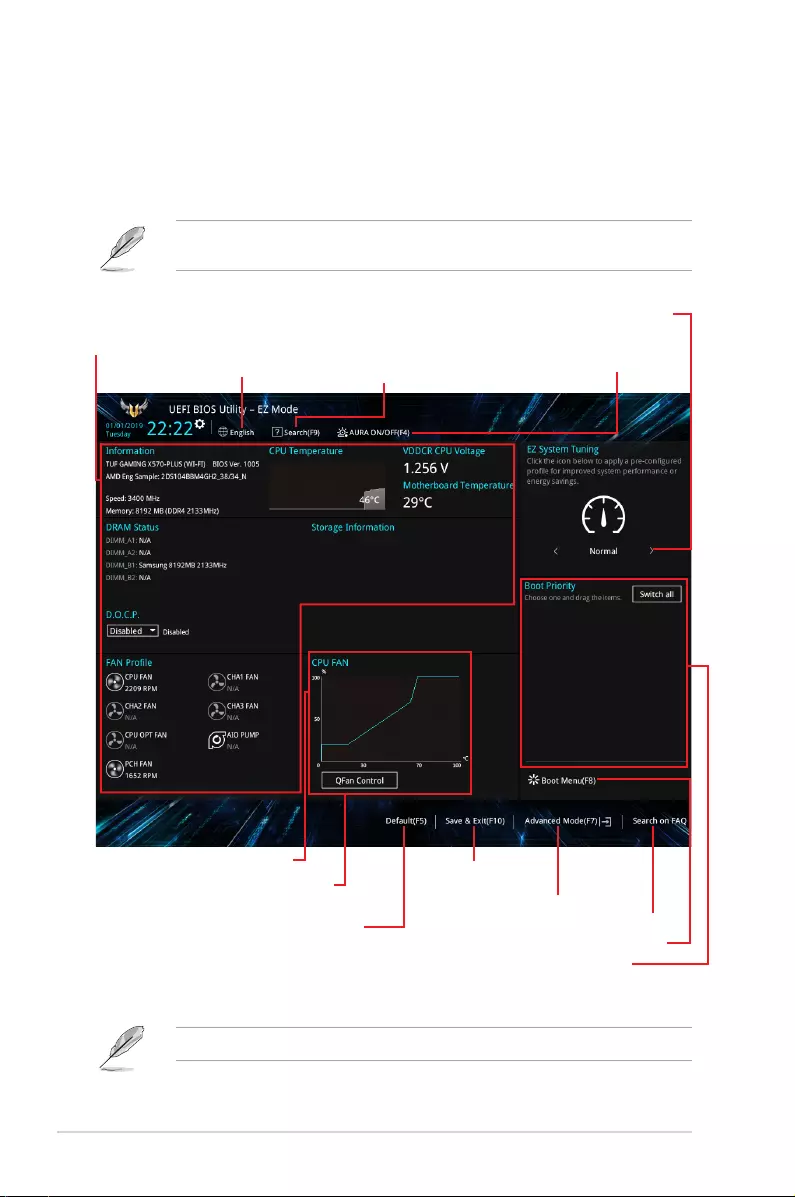
6PRIME/PRO/TUF GAMING X570 Series BIOS Manual
1.2.1 EZ Mode
The EZ Mode provides you an overview of the basic system information, and allows you to
select the display language, system performance, mode and boot device priority. To access
the Advanced Mode, select Advanced Mode or press the <F7> hotkey for the advanced
BIOS settings.
The default screen for entering the BIOS setup program can be changed. Refer to the
Setup Mode item in section Boot menu for details.
The boot device options vary depending on the devices you installed to the system.
Selects the display language
of the BIOS setup program
Displays the CPU/motherboard
temperature, CPU voltage output,
CPU/chassis/power fan speed, and
SATA information
Displays the system properties of the selected mode.
Click < or > to switch EZ System Tuning modes
Loads optimized
default settings
Displays the CPU Fan’s speed. Click
the button to manually tune the fans
Enables or disables the SATA RAID mode
for Intel Rapid Storage Technology Saves the changes
and resets the system
Click to display boot devices
Selects the boot device priority
Click to go to Advanced mode
Search on the FAQ
Turns the RGB LED lighting
or functional LED on or off
Searches by BIOS item name,
enter the item name to nd the
related item listing
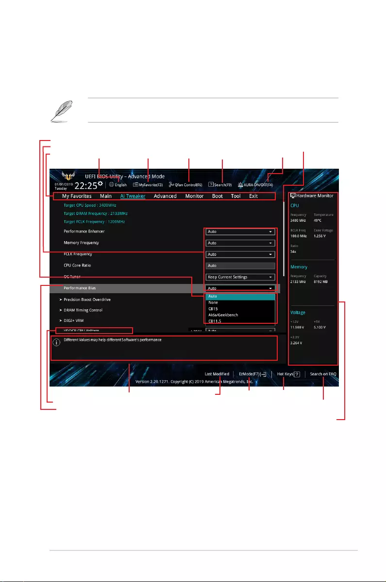
PRIME/PRO/TUF GAMING X570 Series BIOS Manual 7
1.2.2 Advanced Mode
The Advanced Mode provides advanced options for experienced end-users to congure
the BIOS settings. The gure below shows an example of the Advanced Mode. Refer to the
following sections for the detailed congurations.
To switch from EZ Mode to Advanced Mode, click Advanced Mode(F7) or press the <F7>
hotkey.
Menu items
General help
Menu bar Language AURA ON/OFF
Qfan Control(F6)
MyFavorite(F3)
Scroll bar
Pop-up Menu
Conguration elds
Last modied settings Go back to EZ Mode
Displays a quick overview
of the system status
Search on the FAQ
submenu items
Search(F9)
Hot keys

8PRIME/PRO/TUF GAMING X570 Series BIOS Manual
Menu items
The highlighted item on the menu bar displays the specic items for that menu. For example,
selecting Main shows the Main menu items.
The other items (My Favorites, Ai Tweaker, Advanced, Monitor, Boot, Tool, and Exit) on the
menu bar have their respective menu items.
Submenu items
An arrow sign (>) before each item on any menu screen means that the item has a submenu.
To display the submenu, select the item and press <Enter>.
Language
This button above the menu bar contains the languages that you can select for your BIOS.
Click this button to select the language that you want to display in your BIOS screen.
My Favorites (F3)
This button above the menu bar shows all BIOS items in a Tree Map setup. Select frequently-
used BIOS settings and save it to MyFavorites menu.
Refer to section 1.3 My Favorites for more information.
QFan Control (F6)
This button above the menu bar displays the current settings of your fans. Use this button to
manually tweak the fans to your desired settings.
Refer to section 1.2.3 QFan Control for more information.
Menu bar
The menu bar on top of the screen has the following main items:
My Favorites For saving the frequently-used system settings and conguration.
Main For changing the basic system conguration
Ai Tweaker For changing the overclocking settings
Advanced For changing the advanced system settings
Monitor For displaying the system temperature, power status, and changing
the fan settings.
Boot For changing the system boot conguration
Tool For conguring options for special functions
Exit For selecting the exit options and loading default settings

PRIME/PRO/TUF GAMING X570 Series BIOS Manual 9
Search on FAQ
Move your mouse over this button to show a QR code, scan this QR code on your mobile
device to connect to the BIOS FAQ web page of the ASUS support website. You can also
scan the following QR code:
Hot keys
This button above the menu bar contains the navigation keys for the BIOS setup program.
Use the navigation keys to select items in the menu and change the settings.
Scroll bar
A scroll bar appears on the right side of a menu screen when there are items that do not t
on the screen. Press the Up/Down arrow keys or <Page Up> / <Page Down> keys to display
the other items on the screen.
General help
At the bottom of the menu screen is a brief description of the selected item. Use <F12> key
to capture the BIOS screen and save it to the removable storage device.
Conguration elds
These elds show the values for the menu items. If an item is user-congurable, you can
change the value of the eld opposite the item. You cannot select an item that is not
user-congurable.
A congurable eld is highlighted when selected. To change the value of a eld, select it and
press <Enter> to display a list of options.
Last Modied button
This button shows the items that you last modied and saved in BIOS Setup.
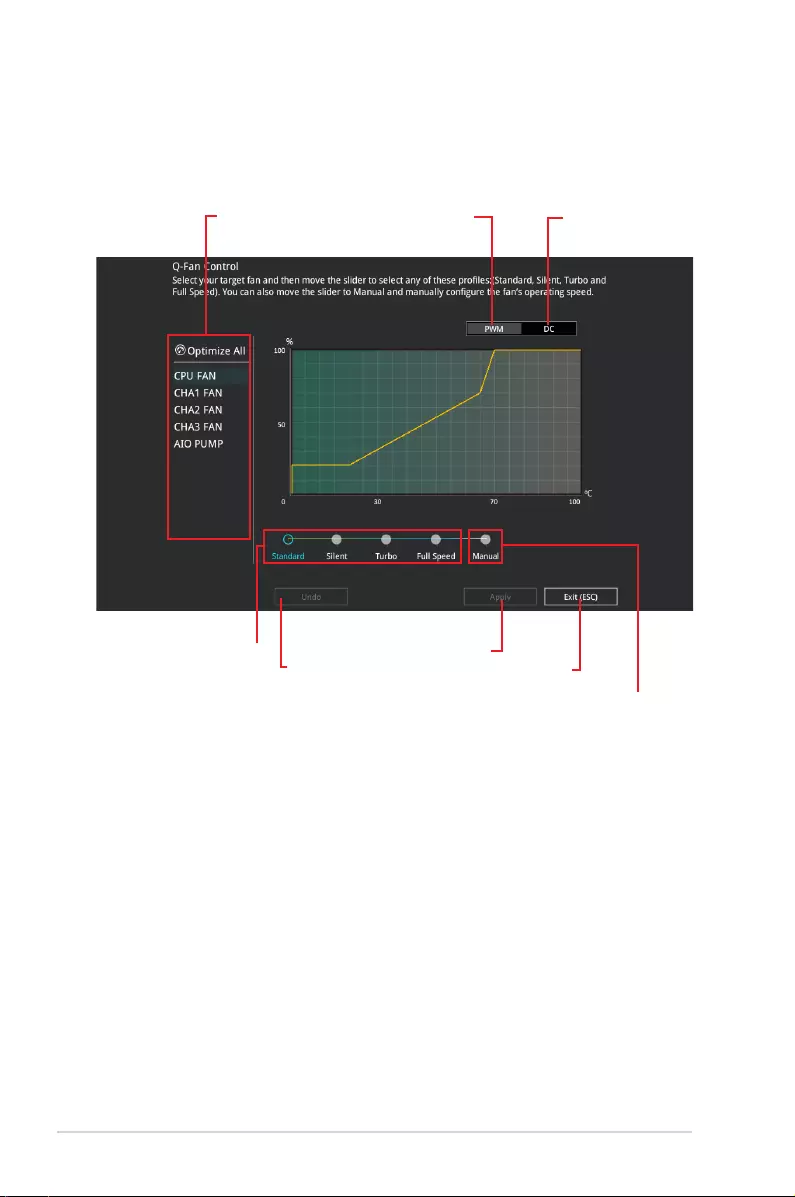
10 PRIME/PRO/TUF GAMING X570 Series BIOS Manual
1.2.3 QFan Control
The QFan Control allows you to set a fan prole or manually congure the operating speed of
your CPU and chassis fans.
Click to select a fan to be
congured Click to activate
PWM Mode
Click to undo the
changes
Click to apply the fan setting
Click to go back to main menu
Select a prole to
apply to your fans
Click to activate DC Mode
Select to manually congure
your fans
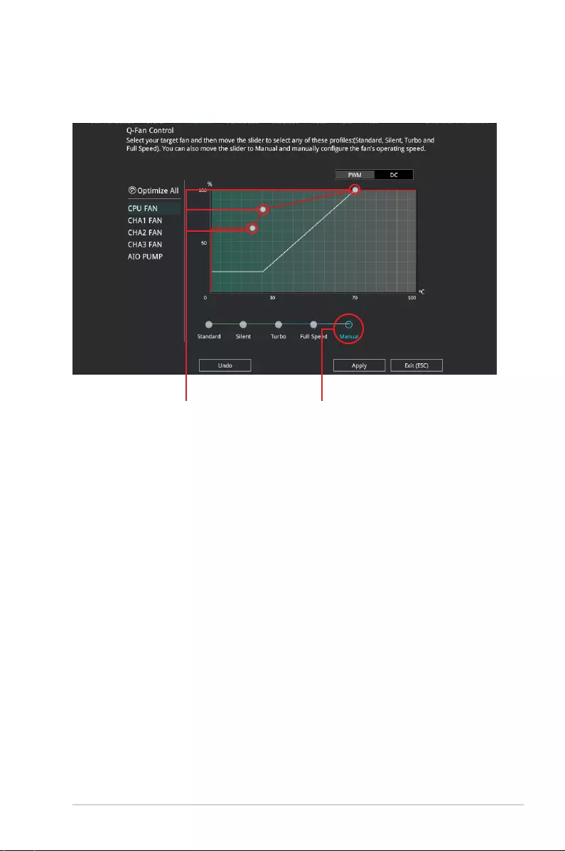
PRIME/PRO/TUF GAMING X570 Series BIOS Manual 11
Speed points Select to manually
congure your fans
Conguring fans manually
Select Manual from the list of proles to manually congure your fans’ operating speed.
To congure your fans:
1. Select the fan that you want to congure and to view its current status.
2. Click and drag the speed points to adjust the fans’ operating speed.
3. Click Apply to save the changes then click Exit (ESC).
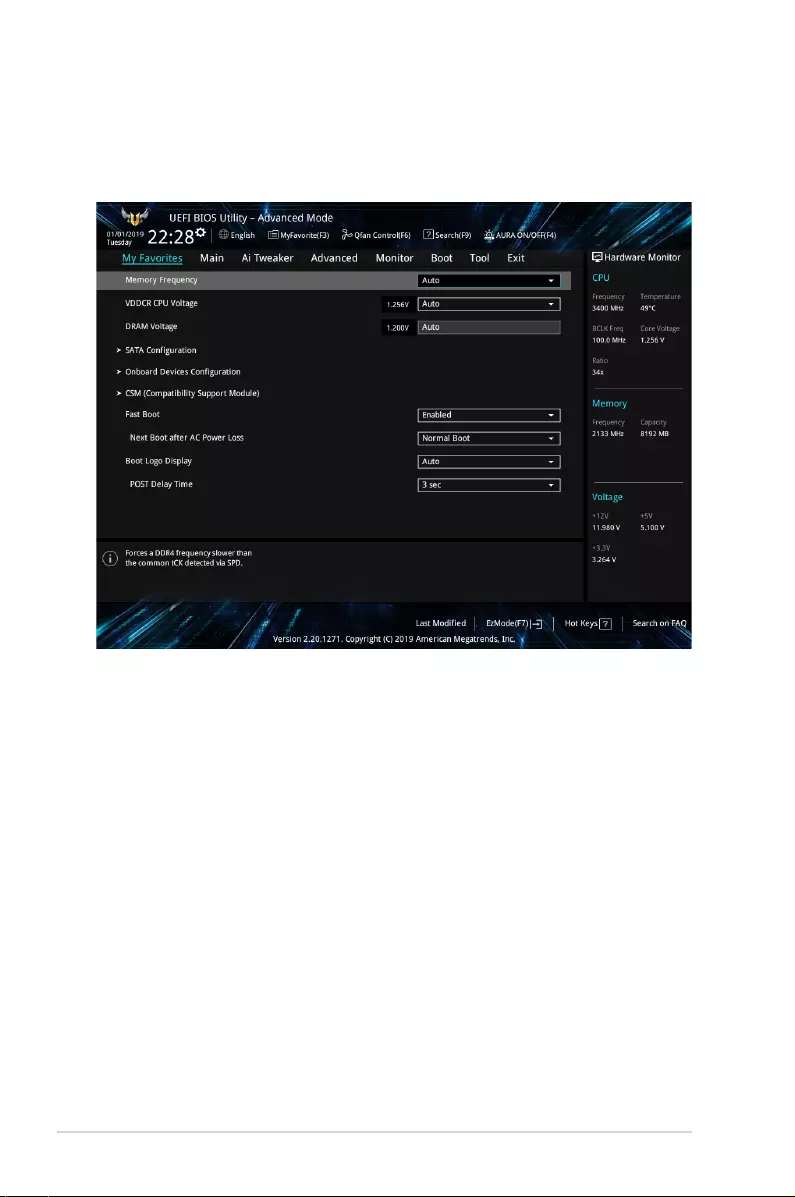
12 PRIME/PRO/TUF GAMING X570 Series BIOS Manual
1.3 My Favorites
My Favorites is your personal space where you can easily save and access your favorite
BIOS items. You can personalize this screen by adding or removing items.
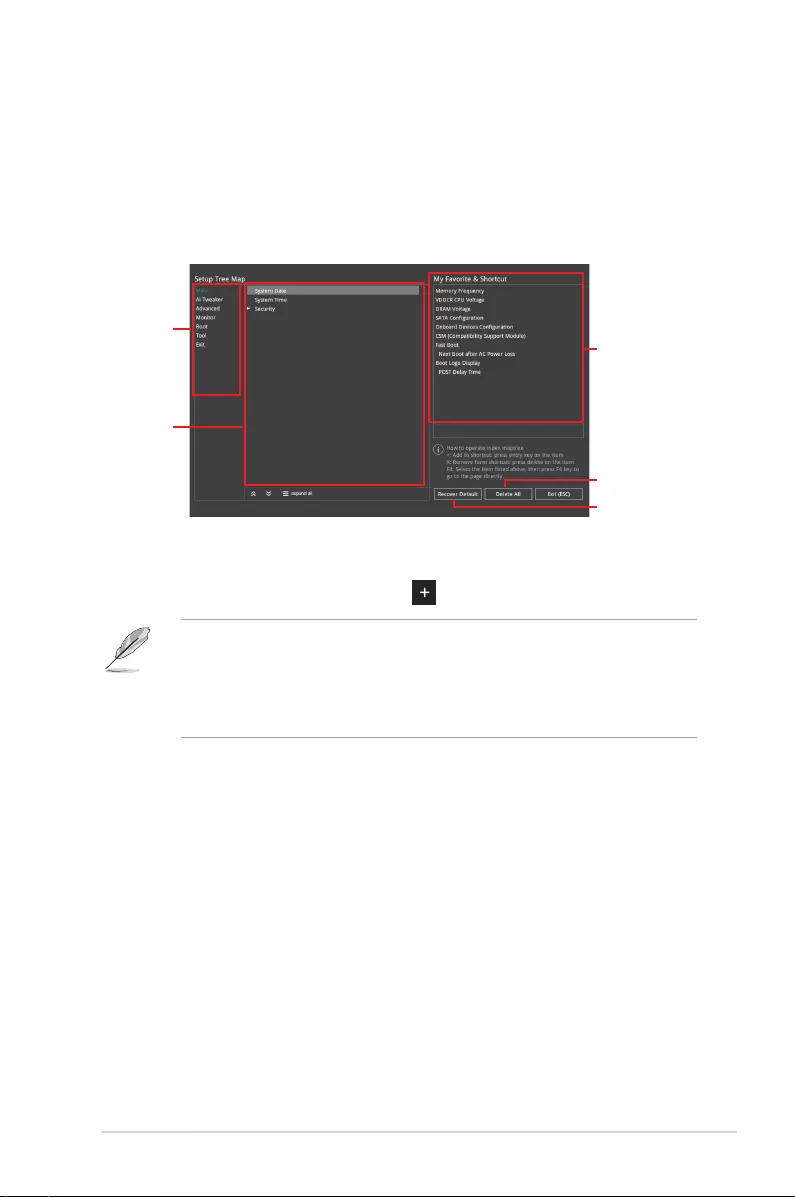
PRIME/PRO/TUF GAMING X570 Series BIOS Manual 13
Adding items to My Favorites
To add BIOS items:
1. Press <F3> on your keyboard or click MyFavorites(F3) from the BIOS screen to open
Setup Tree Map screen.
2. On the Setup Tree Map screen, select the BIOS items that you want to save in My
Favorites screen.
3. Select an item from main menu panel, then click the submenu that you want to save as
favorite from the submenu panel and click or press <Enter> on your keyboard.
You cannot add the following items to My Favorite items:
• Items with submenu options.
• User-managed items such as language and boot order.
• Conguration items such as Memory SPD Information, system time and date.
4. Click Exit (ESC) or press <Esc> key to close Setup Tree Map screen.
5. Go to My Favorites menu to view the saved BIOS items.
Main menu panel
Submenu panel
Selected shortcut
items
Delete all favorite
items
Recover to default
favorite items
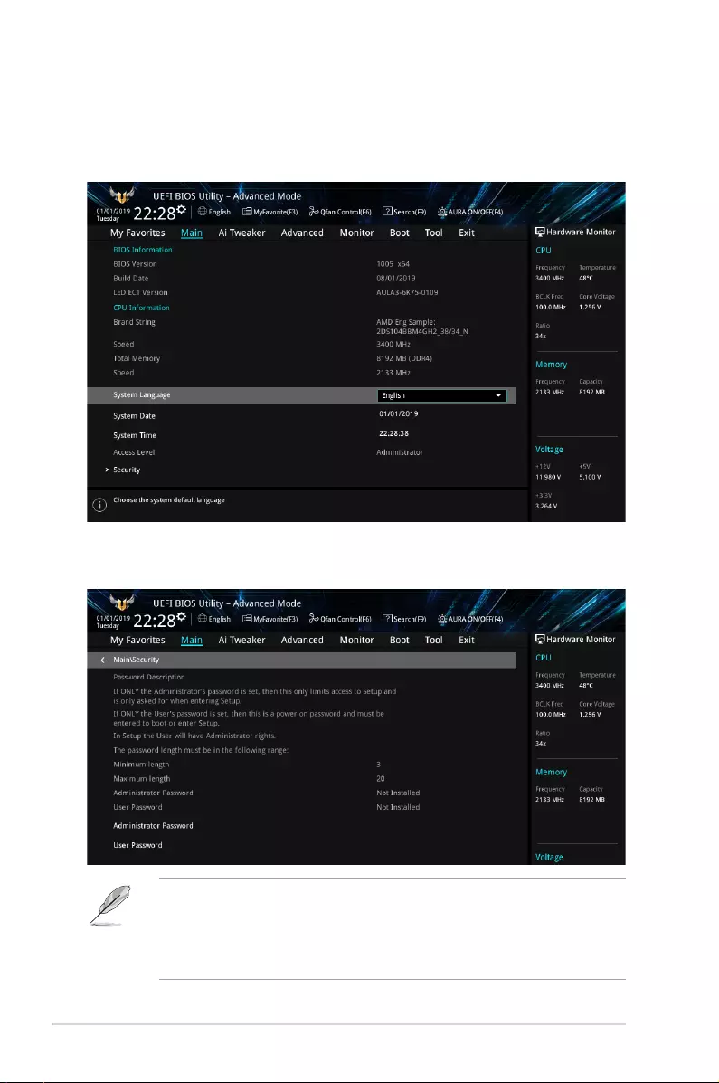
14 PRIME/PRO/TUF GAMING X570 Series BIOS Manual
1.4 Main menu
The Main menu screen appears when you enter the Advanced Mode of the BIOS Setup
program. The Main menu provides you an overview of the basic system information, and
allows you to set the system date, time, language, and security settings.
Security
The Security menu items allow you to change the system security settings.
• If you have forgotten your BIOS password, erase the CMOS Real Time Clock (RTC)
RAM to clear the BIOS password. See the motherboard for information on how to
erase the RTC RAM via the Clear CMOS jumper.
• The Administrator or User Password items on top of the screen show the default [Not
Installed]. After you set a password, these items show [Installed].

PRIME/PRO/TUF GAMING X570 Series BIOS Manual 15
Administrator Password
If you have set an administrator password, we recommend that you enter the administrator
password for accessing the system. Otherwise, you might be able to see or change only
selected elds in the BIOS setup program.
To set an administrator password:
1. Select the Administrator Password item and press <Enter>.
2. From the Create New Password box, key in a password, then press <Enter>.
3. Re-type to conrm the password then select OK.
To change an administrator password:
1. Select the Administrator Password item and press <Enter>.
2. From the Enter Current Password box, key in the current password, then press
<Enter>.
3. From the Create New Password box, key in a new password, then press <Enter>.
4. Re-type to conrm the password then select OK.
To clear the administrator password, follow the same steps as in changing an administrator
password, but leave other elds blank then select OK to continue. After you clear the
password, the Administrator Password item on top of the screen shows [Not Installed].
User Password
If you have set a user password, you must enter the user password for accessing the system.
The User Password item on top of the screen shows the default [Not Installed]. After you set
a password, this item shows [Installed].
To set a user password:
1. Select the User Password item and press <Enter>.
2. From the Create New Password box, key in a password, then press <Enter>.
3. Re-type to conrm the password then select OK.
To change a user password:
1. Select the User Password item and press <Enter>.
2. From the Enter Current Password box, key in the current password, then press
<Enter>.
3. From the Create New Password box, key in a new password, then press <Enter>.
4. Re-type to conrm the password then select OK.
To clear the user password, follow the same steps as in changing a user password, but
leave other elds blank then select OK to continue. After you clear the password, the User
Password item on top of the screen shows [Not Installed].
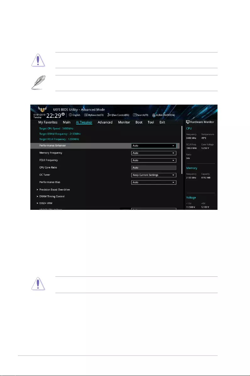
16 PRIME/PRO/TUF GAMING X570 Series BIOS Manual
1.5 Ai Tweaker menu
The Ai Tweaker menu items allow you to congure overclocking-related items.
Be cautious when changing the settings of the Ai Tweaker menu items. Incorrect eld
values can cause the system to malfunction.
The conguration options for this section vary depending on the CPU and DIMM model you
installed on the motherboard.
Scroll down to display other BIOS items.
Performance Enhancer
This item allows the CPU to maintain boost frequencies longer for a better performance.
Conguration options: [Auto] [Default] [Level 1] [Level 2] [Level 3 (OC)]
Memory Frequency
This item allows you to set the memory operating frequency. The congurable options vary
with the BCLK (base clock) frequency setting. Select the auto mode to apply the optimized
setting.
Conguration options: [Auto] [DDR4-1333MHz] – [DDR4-6000MHz]
Selecting a very high memory frequency may cause the system to become unstable! If this
happens, revert to the default setting.
FCLK Frequency
This item allows you to specify the FCLK frequency.
Conguration options: [Auto] [666MHz] [800MHz] – [3000MHz]

PRIME/PRO/TUF GAMING X570 Series BIOS Manual 17
CPU Core Ratio
This item allows you to set the CPU core ratio limit per core or synchronize automatically to
all cores.
Conguration options: [Auto]
OC Tuner
The OC tuner automatically overclocks the CPU and DRAM frequencies and voltages
respectively to enhance the system performance. It also boosts the CPU graphics
performance according to the CPU graphics loading. Conguration options: [Keep Current
Settings] [OC Tuner]
To keep the current overclocking tuner status, select [Keep Current Settings].
Performance Bias
This item allows you to select different values to help different Software’s performance.
Conguration options: [Auto] [None] [CB15] [Aida/Geekbench] [CB11.5]
Precision Boost Overdrive
This item allows the processor to run beyond the dened values for PPT, VDD_CPU EDC,
VDD_CPU TDC, VDD_SOC EDC, VDD_SOC TDC set as the boards limits, and allows it to
boost at higher voltages for a longer duration.
Conguration options: [Auto] [Disabled] [Enabled] [Manual]
Precision Boost Overdrive Scalar
This item allows you to set the scale of the CPU frequency boost.
Conguration options: [Auto] [Manual]
Max CPU Boost Clock Override
This item allows you to increase the maximum CPU frequency that may be automatically
achieved by the Precision Boost 2 algorithhm.
Conguration options: [Auto] [0MHz] [25MHz] [75MHz] [100MHz] [125MHz] [150MHz]
[175MHz] [200MHz]
Platform Thermal Throttle Limit
This item allows you to decrease the maximum allowed processor temperature (celsius).
Conguration options: [Auto] [Manual]

18 PRIME/PRO/TUF GAMING X570 Series BIOS Manual
DRAM Timing Control
The sub-items in this menu allow you to set the DRAM timing control features. Use the
<+> and <-> keys to adjust the value. To restore the default setting, type [auto] using the
keyboard and press the <Enter> key.
Changing the values in this menu may cause the system to become unstable! If this
happens, revert to the default settings.
DRAM CAS# Latency
Conguration options: [Auto] [5] – [33]
Trcdrd
Conguration options: [Auto] [8] – [27]
Trcdwr
Conguration options: [Auto] [8] – [27]
DRAM RAS# PRE Time
Conguration options: [Auto] [5] – [27]
DRAM RAS# ACT Time
Conguration options: [Auto] [8] – [58]
Trc
Conguration options: [Auto] [29] – [135]
TrrdS
Conguration options: [Auto] [4] – [12]
TrrdL
Conguration options: [Auto] [4] – [12]
Tfaw
Conguration options: [Auto] [6] – [54]
TwtrS
Conguration options: [Auto] [2] – [14]
TwtrL
Conguration options: [Auto] [2] – [14]
Twr
Conguration options: [Auto] [10] – [81]
Trcpage
Conguration options: [Auto] [0]
TrdrdScl
Conguration options: [Auto] [1] – [15]
TwrwrScl
Conguration options: [Auto] [1] – [63]

PRIME/PRO/TUF GAMING X570 Series BIOS Manual 19
Trfc
Conguration options: [Auto] [60] – [990]
Trfc2
Conguration options: [Auto] [60] – [990]
Trfc4
Conguration options: [Auto] [60] – [990]
Tcwl
Conguration options: [Auto] [9] – [22]
Trtp
Conguration options: [Auto] [5] – [14]
Trdwr
Conguration options: [Auto] [1] – [31]
Twrrd
Conguration options: [Auto] [1] – [15]
TwrwrSc
Conguration options: [Auto] [1] – [15]
TwrwrSd
Conguration options: [Auto] [1] – [15]
TwrwrDd
Conguration options: [Auto] [1] – [15]
TrdrdSc
Conguration options: [Auto] [1] – [15]
TrdrdSd
Conguration options: [Auto] [1] – [15]
TrdrdDd
Conguration options: [Auto] [1] – [15]
Tcke
Conguration options: [Auto] [1] – [31]
ProcODT
Conguration options: [Auto] [High Impedance] [480ohm] [240ohm] [160ohm] [120ohm]
[96ohm] [80ohm] [68.6ohm] [60ohm] [53.3ohm] [43.6ohm] [40ohm] [36.9ohm]
[34.3ohm] [32ohm] [30ohm] [28.2ohm]
Cmd2T
Conguration options: [Auto] [1T] [2T]
Gear Down Mode
Conguration options: [Auto] [Enabled] [Disabled]
Power Down Enable
Conguration options: [Auto] [Enabled] [Disabled]

20 PRIME/PRO/TUF GAMING X570 Series BIOS Manual
RttNom
Conguration options: [Auto] [Rtt_Nom Disable] [RZQ/4] [RZQ/2] [RZQ/6] [RZQ/1]
[RZQ/5] [RZQ/3] [RZQ/7]
RttWr
Conguration options: [Auto] [Dynamic ODT Off] [RZQ/2] [RZQ/1] [Hi-Z] [RZQ/3]
RttPark
Conguration options: [Auto] [Rtt_PARK Disable] [RZQ/4] [RZQ/2] [RZQ/6] [RZQ/1]
[RZQ/5] [RZQ/3] [RZQ/7]
MemAddrCmdSetup
Conguration options: [Auto] [0]-[63]
MemCsOdtSetup
Conguration options: [Auto] [0]-[63]
MemCkeSetup
Conguration options: [Auto] [0]-[63]
MemCadBusClkDrvStren
Conguration options: [Auto] [120.0 Ohm] [60.0 Ohm] [40.0 Ohm] [30.0 Ohm] [24.0
Ohm] [20.0 Ohm]
MemCadBusAddrCmdDrvStren
Conguration options: [Auto] [120.0 Ohm] [60.0 Ohm] [40.0 Ohm] [30.0 Ohm] [24.0
Ohm] [20.0 Ohm]
MemCadBusCsOdtDrvStren
Conguration options: [Auto] [120.0 Ohm] [60.0 Ohm] [40.0 Ohm] [30.0 Ohm] [24.0
Ohm] [20.0 Ohm]
MemCadBusCkeDrvStren
Conguration options: [Auto] [120.0 Ohm] [60.0 Ohm] [40.0 Ohm] [30.0 Ohm] [24.0
Ohm] [20.0 Ohm]
CLDO VDDP voltage
Conguration options: [Auto] [700]- [66234]
PRIME/PRO/TUF GAMING X570 Series BIOS Manual 21
DIGI+ VRM
Changing the values in this menu may cause the system to become unstable! If this
happens, revert to the default settings.
VDDCR CPU Load-line Calibration
Load-line affects CPU power voltage. The CPU working voltage decreases
proportionally to CPU loading. Higher load-line calibration could get higher voltage and
good overclocking performance, but increases the CPU and VRM thermal conditions.
Select from levels 1 to 7 to adjust the load-line slope.
Conguration options [Auto] [Default] [Level 1] — [Level 7]
The actual performance boost may vary depending on your CPU specication.
DO NOT remove the thermal module. The thermal conditions should be monitored.
VDDCR CPU Current Capability
This item allows you to set the shut off current limit for external voltage regulator. A
higher setting will allow the voltage regulator to supply more current while a lower
setting will cause the voltage regulator to shut off the system when the supplied current
is higher than the set value.
Conguration options: [100%] [110%] [120%] [130%]
Congure higher values when overclocking or under a high CPU loading for extra power
support.
VDDCR CPU Switching Frequency
This item allows you to set a higher frequency for a quicker transient response speed.
Use the <+> or <-> to adjust the value. The values range from 200 to 350 with an
interval of 50.
DO NOT remove the thermal module. The thermal conditions should be monitored.
VDDCR CPU Power Phase Control
This item allows you to set the power phase control of the CPU.
[Manual] Phase number is adjusted by current(A) step.
[Optimized] Set to the ASUS optimized phase tuning prole.
[Extreme] Set to the full phase mode.
The following item appears only when the VDDCR CPU Power Phase Control is set to
[Manual].

22 PRIME/PRO/TUF GAMING X570 Series BIOS Manual
Manual Adjustment
This item allows you to set the response time, selecting [Regular] will
result in longer reaction times.
Conguration options: [Regular] [Medium] [Fast] [Ultra Fast]
VDDCR CPU Power Duty Control
This item allows you to set the duty cycle of each VRM phase based upon current and/
or temperature.
[T.Probe] Sets the buck controller to balance VRM FET temperatures.
[Extreme] Sets the buck controller to balance per phase current.
DO NOT remove the thermal module. The thermal conditions should be monitored.
VDDCR SOC Load line Calibration
Conguration options: [Auto] [Level 1] – [Level 5]
VDDCR SOC Current Capability
Conguration options: [100%] [110%] [120%] [130%]
VDDCR SOC Switching Frequency
Conguration options: [200] [250] [300] [350]
VDDCR SOC Power Phase Control
Conguration options: [Optimized] [Extreme] [Manual]
The following item appears only when the VDDCR SOC Power Phase Control is set to
[Manual].
Manual Adjustment
This item allows you to set the response time, selecting [Regular] will
result in longer reaction times.
Conguration options: [Regular] [Medium] [Fast] [Ultra Fast]
VDDCR CPU Voltage
Conguration options: [Auto] [Manual Mode] [Offset Mode]
The following item appears only when you set the VDDCR CPU Voltage to [Manual
Mode].
VDDCR CPU Voltage Override
Conguration options: [Auto] [0.750] — [2.000]
The following items appear only when you set the VDDCR CPU Voltage to [Offset Mode].
VDDCR CPU Offset Mode Sign
[+] To offset the voltage by a positive value.
[–] To offset the voltage by a negative value.
VDDCR CPU Offset Voltage
Conguration options: [Auto] [-0.00625] — [+0.50000]

PRIME/PRO/TUF GAMING X570 Series BIOS Manual 23
DRAM Voltage
Conguration options: [Auto] [1.20] – [1.80]
CLDO VDDG voltage
Conguration options: [Auto] [0.700] – [1.199]
1.0V SB Voltage
Conguration options: [Auto] [1.05] – [1.1]
1.2V SB Voltage
Conguration options: [Auto] [1.2] – [1.25]
CPU 1.80V Voltage
Conguration options: [Auto] [1.80] – [1.85]
VTTDDR Voltage
Conguration options: [Auto] [1/2VDDQ] – [1/2VDDQ+0.2V]
VPP_MEM Voltage
Conguration options: [Auto] [2.500] – [2.800]
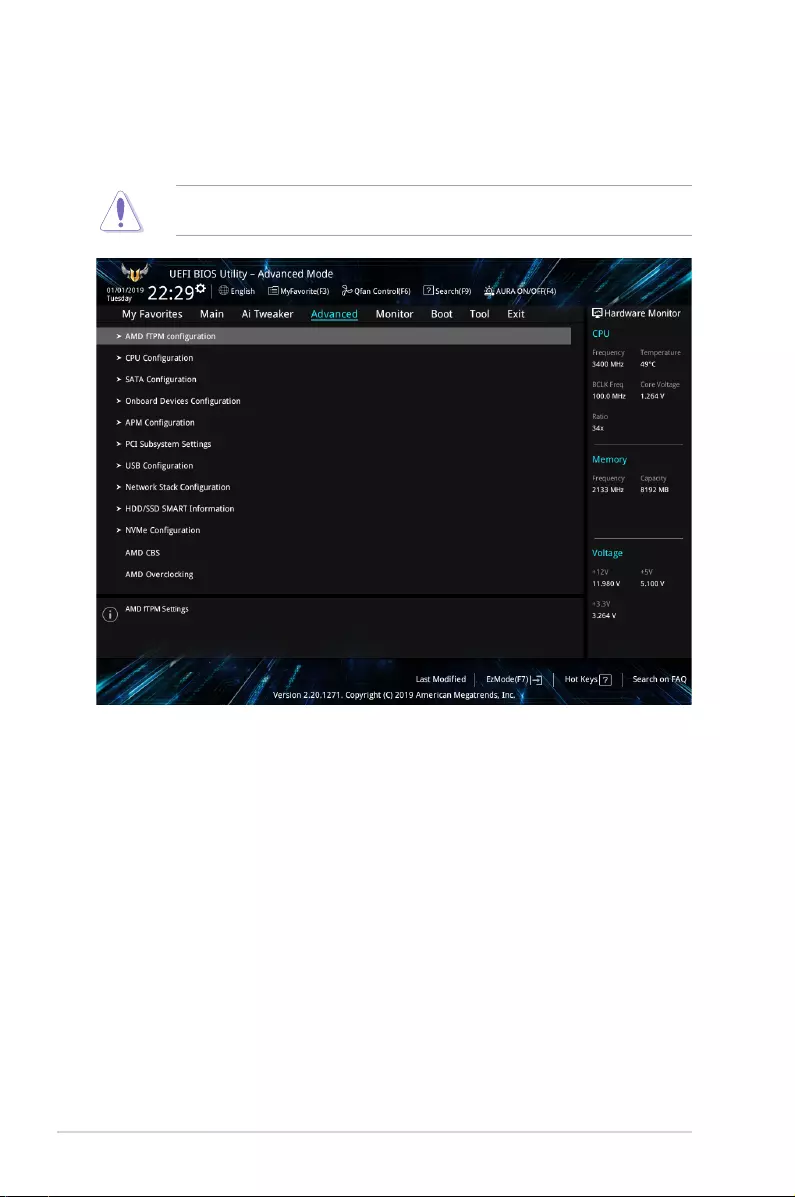
24 PRIME/PRO/TUF GAMING X570 Series BIOS Manual
1.6 Advanced menu
The Advanced menu items allow you to change the settings for the CPU and other system
devices.
Be cautious when changing the settings of the Advanced menu items. Incorrect eld values
can cause the system to malfunction.
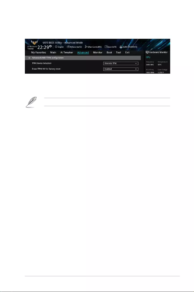
PRIME/PRO/TUF GAMING X570 Series BIOS Manual 25
1.6.1 AMD fTPM conguration
The items in this menu show the AMD fTPM conguration options.
TPM Device Selection
This item allows you to select the TPM device. Conguration options: [Discrete
TPM] [Firmware TPM]
When Firmware TPM is set to disabled all saved data on it will be lost.
Erase fTPM NV for factory reset
This item allows you to enable or disable fTPM reset for newly installed CPUs.
[Disabled] Keep previous fTPM records and continue system boot, fTPM will not be
enabled with the new CPU unless fTPM is reset (reinitialized). Swapping
back to the old CPU may allow you to recover TPM related keys and data.
[Enabled] Reset fTPM, if you have Bitlocker or encryption-enabled system, the
system will not boot without a recovery key.
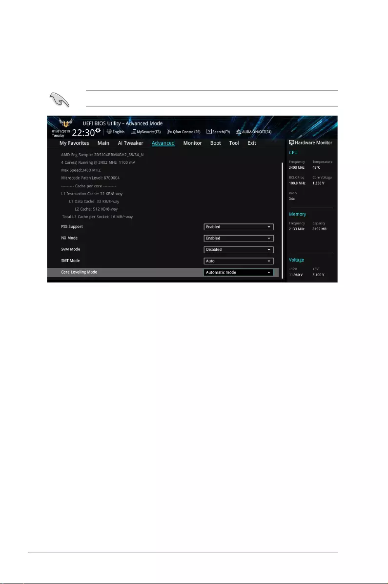
26 PRIME/PRO/TUF GAMING X570 Series BIOS Manual
1.6.2 CPU Conguration
The items in this menu show the CPU-related information that the BIOS automatically
detects.
The items in this menu may vary based on the CPU installed.
PSS Support
This item allows you enable or disable the generation of ACPI_PPC, _PSS, and _PCT
objects.
Conguration options: [Disabled] [Enabled]
NX Mode
This item allows you enable or disable No-execute page protection function.
Conguration options: [Disabled] [Enabled]
SVM Mode
This item allows you enable or disable CPU Virtualization.
Conguration options: [Disabled] [Enabled]
SMT Mode
Conguration options: [Auto] [Disabled]
Core Leveling Mode
This item allows you to change the number of compute units in the system.
Conguration options: [Automatic mode] [Two core per processor]
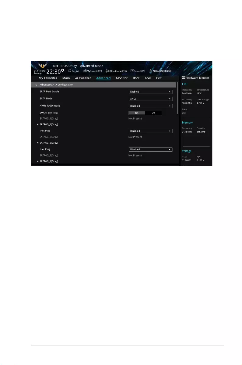
PRIME/PRO/TUF GAMING X570 Series BIOS Manual 27
1.6.3 SATA Conguration
While entering Setup, the BIOS automatically detects the presence of SATA devices. The
SATA Port items show Not Present if no SATA device is installed to the corresponding SATA
port.
SATA Port Enable
This item allows you to enable or disable the SATA Device.
Conguration options: [Disabled] [Enabled]
SATA Mode
This item allows you to set the SATA conguration.
[AHCI] Set to [AHCI] when you want the SATA hard disk drives to use the
AHCI (Advanced Host Controller Interface). The AHCI allows the
onboard storage driver to enable advanced Serial ATA features that
increases storage performance on random workloads by allowing
the drive to internally optimize the order of commands.
[RAID] Set to [RAID] when you want to create a RAID conguration from
the SATA hard disk drives.
NVMe RAID Mode
This item allows you to enable or disable the NVMe RAID mode.
Conguration options: [Disabled] [Enabled]
SMART Self Test
S.M.A.R.T. (Self-Monitoring, Analysis and Reporting Technology) is a monitoring system that
shows a warning message during POST (Power-on Self Test) when an error occurs in the
hard disks.
Conguration options: [On] [Off]
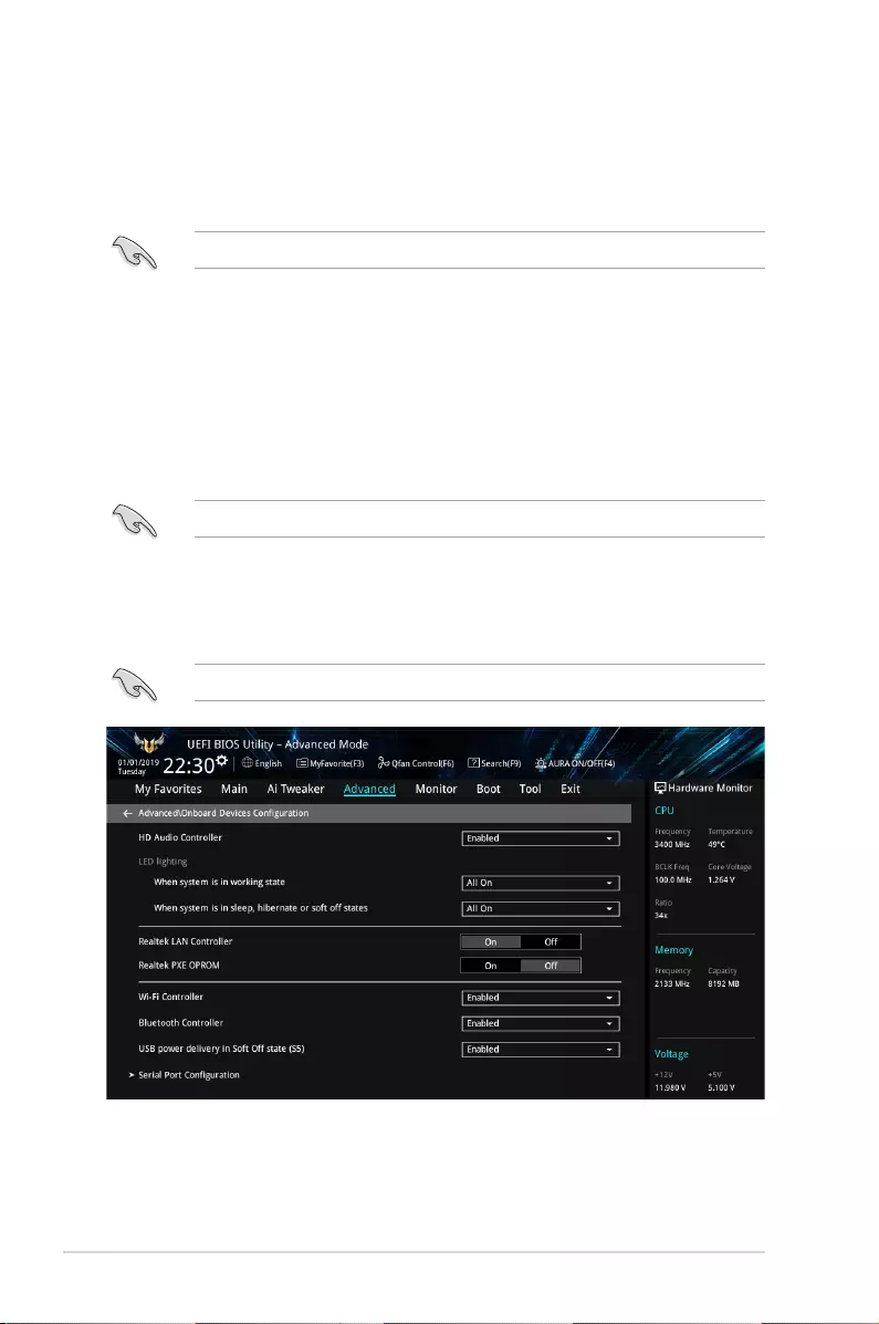
28 PRIME/PRO/TUF GAMING X570 Series BIOS Manual
SATA6G_1(Gray) — SATA6G_8(Gray)
SATA6G_1 — SATA6G_8
This item allows you to enable or disable the selected SATA port.
Conguration options: [Disabled] [Enabled]
The number of the SATA ports varies by motherboard models.
Hot Plug
These items appears only when the SATA Mode is set to [AHCI] and allows you to
enable or disable SATA Hot Plug Support.
Conguration options: [Disabled] [Enabled]
M.2_1 — M.2_2
M.2_1 — M.2_2
This item allows you to rename the AMD APU M.2 ports.
The number of the M.2 ports varies by motherboard models.
1.6.4 Onboard Devices Conguration
The items in this menu allow you to switch between PCIe Lanes and congure onboard
devices.
The items in this menu may vary by motherboard models.
HD Audio Controller
This item allows you to use the Azalia High Denition Audio Controller
Conguration options: [Disabled] [Enabled]

PRIME/PRO/TUF GAMING X570 Series BIOS Manual 29
LED lighting
When system is in working state
This item allows you to turn the RGB LED lighting on or off when the system is in the
working state.
Conguration options: [On] [Off]
When system is in sleep, hibernate or soft off states
This item allows you to turn the RGB LED lighting on or off when the system is in the
sleep, hibernate or soft off states.
Conguration options: [On] [Off]
RGB LED availability varies by motherboard models.
Realtek LAN Controller
This item allows you to enable or disable the Realtek LAN controllers.
Conguration options: [On] [Off]
Realtek PXE OPROM
This item allows you to enable or disable Realtek PXE OPROM launch.
Conguration options: [On] [Off]
Intel LAN Controller
This item allows you to enable or disable the Intel LAN controllers.
Conguration options: [On] [Off]
Intel PXE OPROM
This item allows you to enable or disable Intel PXE OPROM launch.
Conguration options: [On] [Off]
Wi-Fi Controller
This item allows you to enable or disable the Wi-Fi controller.
Conguration options: [Disabled] [Enabled]
Wi-Fi Controller availability varies by motherboard models.
Bluetooth Controller
This item allows you to enable or disable the Bluetooth controller.
Conguration options: [Disabled] [Enabled]
Bluetooth Controller availability varies by motherboard models.
USB power delivery in Soft Off state (S5)
This item allows you to enable or disable the USB power delivery when your PC is in the S5
state.
Conguration options: [Enabled] [Disabled]

30 PRIME/PRO/TUF GAMING X570 Series BIOS Manual
Serial Port Conguration
Serial port availability varies by motherboard models.
Serial Port
Allows you to enable or disable Serial Port.
Conguration options: [On] [Off]
The following item appears only when you set Serial Port to [On].
Change Settings
Allows you to choose the setting for Super IO device.
Conguration options: [IO=3F8h; IRQ=4] [IO=2F8h; IRQ=3] [IO=3E8h; IRQ=4]
[IO=2E8h; IRQ=3]

PRIME/PRO/TUF GAMING X570 Series BIOS Manual 31
1.6.5 APM Conguration
The items in this menu allow you to set system wake and sleep settings.
ErP Ready
This item allows you to switch off some power at S4+S5 or S5 to get the system ready for
ErP requirement. When set to [Enabled], all other PME options are switched off.
Conguration options: [Disabled] [Enable(S4+S5)] [Enable(S5)]
Restore AC Power Loss
This item allows your system to go to ON state, OFF state, or both states after an AC power
loss. When setting your system to [Last State], it goes to the previous state before the AC
power loss.
Conguration options: [Power Off] [Power On] [Last State]
Power On By PCI-E
This item allows you to enable or disable the Wake-on-LAN function of the onboard LAN
controller or other installed PCI-E LAN cards.
Conguration options: [Disabled] [Enabled]
Power On By RTC
This item allows you to enable or disable the RTC (Real-Time Clock) to generate a wake
event and congure the RTC alarm date. When enabled, you can set the days, hours,
minutes, or seconds to schedule an RTC alarm date.
Conguration options: [Disabled] [Enabled]
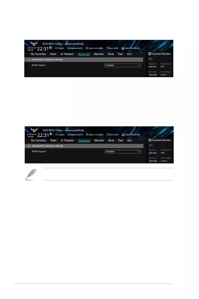
32 PRIME/PRO/TUF GAMING X570 Series BIOS Manual
1.6.6 PCI Subsystem Settings
The items in this menu allow you to set PCI, PCI-X, and PCI Express settings.
SR-IOV Support
This option enables or disables Single Root IO Virtualization Support if the system has SR-
IOV capable PCIe devices.
Conguration options: [Disabled] [Enabled]
1.6.7 USB Conguration
The items in this menu allow you to set PCI, PCI-X, and PCI Express settings.
The Mass Storage Devices item shows the auto-detected values. If no USB device is
detected, the item shows None.
Legacy USB Support
[Enabled] Your system supports the USB devices in legacy operating systems.
[Disabled] Your USB devices can be used for BIOS setup only and cannot be
recognized in the boot devices list.
[Auto] Your system automatically detects the presence of USB devices at startup.
If any USB devices are detected, the legacy USB support is enabled.
XHCI Hand-off
[Enabled] Enables the support for operating systems without an XHCI hand-off
feature.
[Disabled] Disables the XHCI Hand-off support.
USB Device Enable
This item allows you to enable or disable USB devices.
Conguration options: [Disabled] [Enabled]
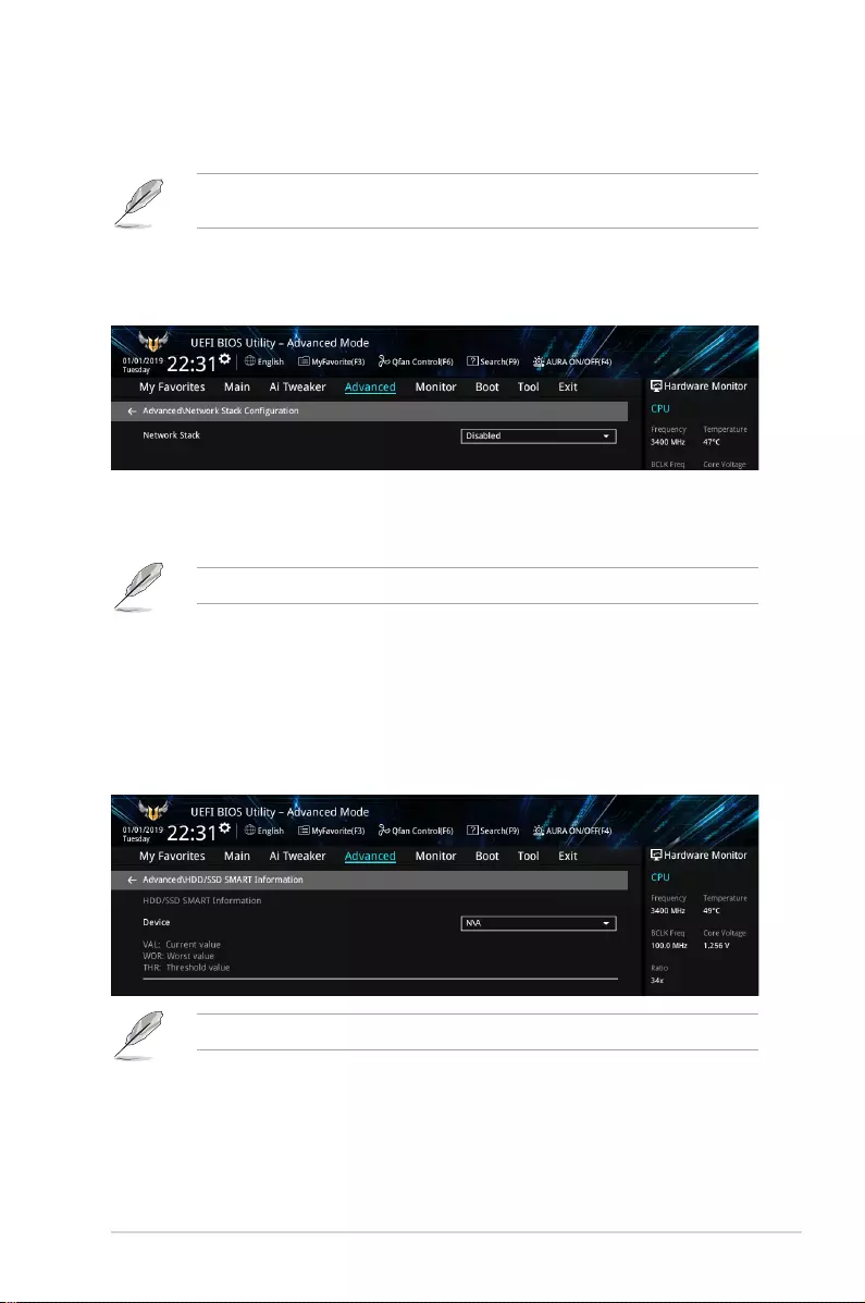
PRIME/PRO/TUF GAMING X570 Series BIOS Manual 33
USB Single Port Control
This item allows you to enable or disable the individual USB ports.
Refer to section Motherboard layout in your motherboard user manual for the location of
the USB ports.
1.6.8 Network Stack Conguration
The items in this menu allow you to enable or disable the UEFI network stack
Network stack
This item allows you to disable or enable the UEFI network stack.
Conguration options: [Disable] [Enable]
The following item appears only when you set Network Stack to [Enabled].
Ipv4/Ipv6 PXE Support
This item allows you to enable or disable the Ipv4/Ipv6 PXE wake event.
Conguration options: [Disabled] [Enabled]
1.6.9 HDD/SSD SMART Information
This menu displays the SMART information of the connected devices.
NVM Express devices do not support SMART information.
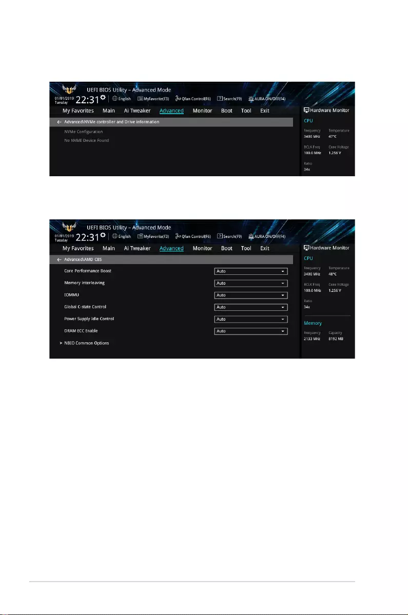
34 PRIME/PRO/TUF GAMING X570 Series BIOS Manual
1.6.10 NVMe Conguration
This menu displays the NVMe controller and Drive information of the connected devices.
1.6.11 AMD CBS
The items in this menu shows the AMD Common BIOS Specications.
Core Performance Boost
Conguration options: [Auto] [Disabled]
Memory interleaving
Conguration options: [Auto] [Disabled]
IOMMU
Conguration options: [Auto] [Disabled] [Enabled]
Global C-state Control
Conguration options: [Auto] [Disabled] [Enabled]
Power Supply Idle Control
Conguration options: [Auto] [Low Current Idle] [Typical Current Idle]
DRAM ECC Enable
Conguration options: [Auto] [Disabled] [Enabled]
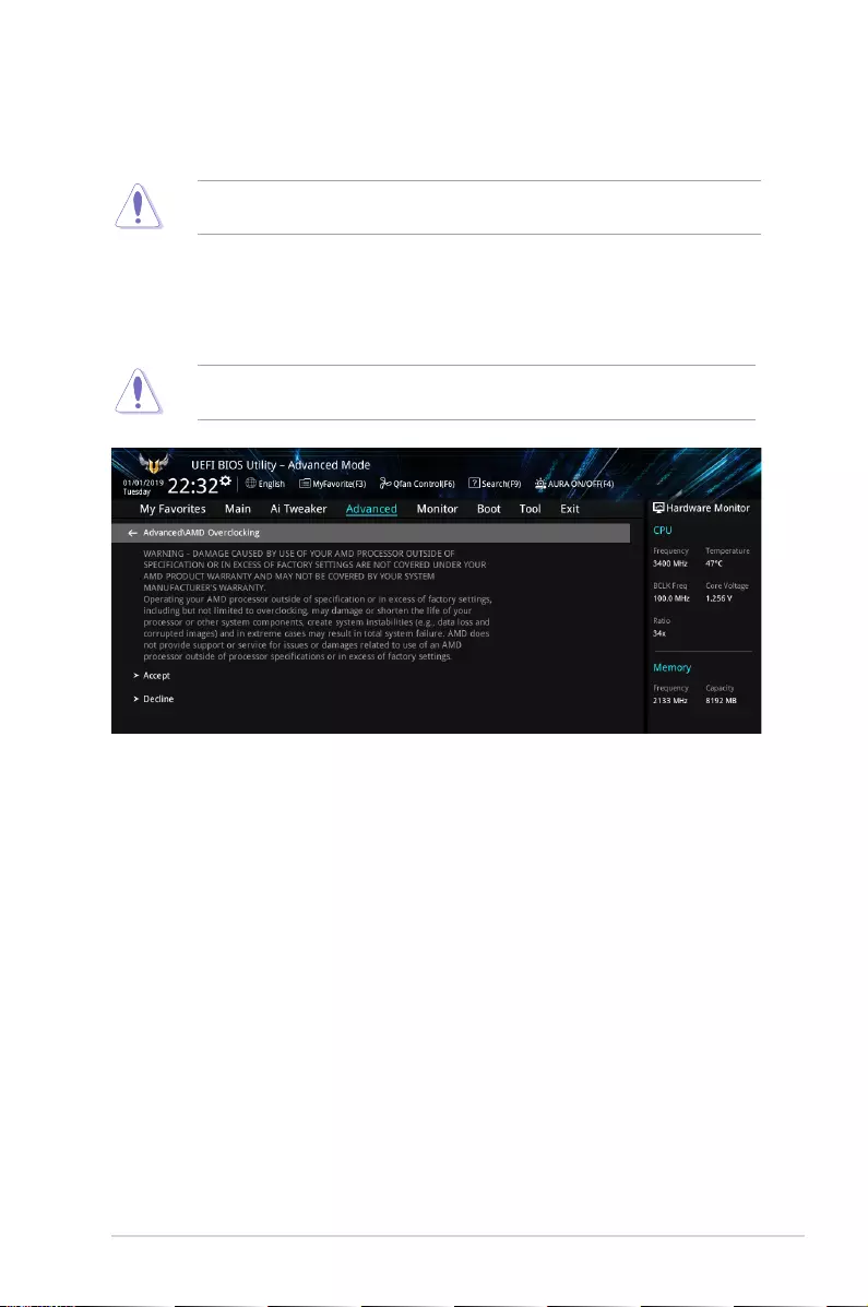
PRIME/PRO/TUF GAMING X570 Series BIOS Manual 35
NBIO Common Options
XFR Enhancement
Damage caused by use of your AMD processor outside of specication or in excess of
factory settings are not covered by your system manufacturers warranty.
1.6.12 AMD Overclocking
The items in this menu allows you to congure the AMD Overclocking setup page.
Damage caused by use of your AMD processor outside of specication or in excess of
factory settings are not covered by your system manufacturers warranty.
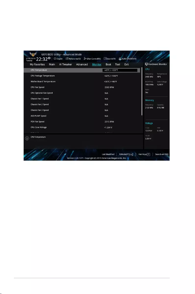
36 PRIME/PRO/TUF GAMING X570 Series BIOS Manual
CPU Temperature, CPU Package Temperature, Motherboard Temperature
[xxx°C/xxx°F]
The onboard hardware monitor automatically detects and displays the CPU, CPU Package,
and motherboard temperatures. Select [Ignore] if you do not wish to display the detected
temperatures.
CPU Fan Speed, CPU Optional Fan, Chassis Fan 1-3 Speed, AIO pump
Speed, PCH Fan Speed [xxxx RPM]
The onboard hardware monitor automatically detects and displays the CPU fan, CPU optional
fan, chassis fan, M.2 fan, AIO pump, and extension fan speed in rotations per minute (RPM).
If the fan is not connected to the motherboard, the eld shows N/A. Select [Ignore] if you do
not wish to display the detected speed.
CPU Core Voltage, 3.3V Voltage, 5V Voltage, 12V Voltage [x.xxxx V]
The onboard hardware monitor automatically detects the voltage output through the onboard
voltage regulators. Select [Ignore] if you do not want to detect this item.
1.7 Monitor menu
The Monitor menu displays the system temperature/power status, and allows you to change
the fan settings.
Scroll down to display the other BIOS items.

PRIME/PRO/TUF GAMING X570 Series BIOS Manual 37
Q-fan Conguration
Q-fan Tuning
Click this item to automatically detect the lowest speed and congure the minimum
duty cycle for each fan.
CPU Q-Fan Control
This item allows you to set the CPU Q-Fan operating mode.
[Auto] Detects the type of CPU fan installed and automatically switches
the control modes.
[PWM Mode] Enables the CPU Q-Fan Control feature in PWM mode for 4-pin
CPU fan.
[DC Mode] Enables the CPU Q-Fan Control feature in DC mode for 3-pin CPU
fan.
[Disabled] Disables the Q-Fan Control.
The following items appear only when you set the CPU Q-Fan Control to [Auto], [PWM
Mode], and [DC Mode].
CPU Fan Step Up/Down
This item allows you to set the value of the CPU fan step up/down.
Conguration options: [0 sec] [2.1 sec] [2.8 sec] [3.6 sec] [4.2 sec] [5.0 sec] [6.3 sec]
[8.5 sec] [12 sec] [25 sec]
CPU Fan Speed Lower Limit
This item allows you to set the low limit warning for CPU Fan speed.
Conguration options: [Ignore] [200 RPM] [300 RPM] [400 RPM] [500 RPM] [600 RPM]
CPU Fan Profile
This item allows you to set the appropriate performance level of the CPU fan.
[Standard] Set to make the CPU fan adjust automatically depending on the CPU
temperature.
[Silent] Set to minimize the fan speed for quiet CPU fan operation.
[Turbo] Set to achieve maximum CPU fan speed.
[Manual] Set to assign the detailed fan speed control parameters.
The following items appear only when you set the CPU Fan Prole to [Manual].
CPU Upper Temperature
Use the <+> and <-> keys to adjust the upper limit of the CPU temperature.
The CPU fan will operate at the maximum duty cycle when the CPU
temperature is higher than the limit.

38 PRIME/PRO/TUF GAMING X570 Series BIOS Manual
CPU Fan Max. Duty Cycle(%)
Use the <+> and <-> keys to adjust the maximum CPU fan duty cycle.
When the CPU temperature reaches the upper limit, the CPU fan will
operate at the maximum duty cycle.
CPU Middle Temperature
Use the <+> and <-> keys to adjust the CPU middle temperature.
CPU Fan Middle. Duty Cycle(%)
Use the <+> or <-> keys to adjust the CPU fan middle duty cycle.
CPU Lower Temperature
Use the <+> or <-> keys to adjust the lower limit of the CPU temperature.
The CPU fan will operate at the minimum duty cycle when the CPU
temperature is lower than the limit.
CPU Fan Min. Duty Cycle(%)
Use the <+> and <-> keys to adjust the minimum CPU fan duty cycle.
When the CPU temperature is lower than the lower limit, the CPU fan will
operate at the minimum duty cycle.
Chassis Fan(s) Configuration
The number of the Chassis Fan varies by motherboard models.
Chassis Fan 1-3 Q-Fan Control
This item allows you to set the chassis fan operating mode.
[Auto] Detects the type of chassis fan installed and automatically switches
the control modes.
[PWM Mode] Enables the Chassis Fan Q-Fan Control feature in PWM mode for
4-pin chassis fan.
[DC Mode] Enables the Chassis Fan Q-Fan Control feature in DC mode for
3-pin chassis fan.
[Disabled] Disables the Q-Fan control.
Chassis Fan 1-3 Q-Fan Source
The assigned fan will be controlled according to the selected temperature source.
Conguration options: [CPU] [MotherBoard] [Multiple Sources]
For Multiple Sources, select up to three temperature sources and the fan will automatically
change based on the highest temperature.
Chassis Fan 1-3 Step Up/Down
This item allows you to set the value of the CPU fan 1-2 step up/down.
Conguration options: [0 sec] [12 sec] [25 sec] [51 sec] [76 sec] [102 sec] [127 sec]
[153 sec] [178 sec] [204 sec]
Chassis Fan 1-3 Fan Speed Low Limit
This item allows you to disable or set the chassis fan warning speed.
Conguration options: [Ignore] [200 RPM] [300 RPM] [400 RPM] [500 RPM] [600 RPM]

PRIME/PRO/TUF GAMING X570 Series BIOS Manual 39
Chassis Fan 1-3 Profile
This item allows you to set the appropriate performance level of the chassis fan.
[Standard] Sets to [Standard] to make the chassis fan automatically adjust
depending on the chassis temperature.
[Silent] Sets to [Silent] to minimize the fan speed for quiet chassis fan
operation.
[Turbo] Sets to [Turbo] to achieve maximum chassis fan speed.
[Manual] Sets to [Manual] to assign detailed fan speed control parameters.
The following items appear only when you set Chassis Fan 1-3 Prole to [Manual].
Chassis Fan 1-3 Upper Temperature
Use the <+> or <-> keys to adjust the upper limit of the Chassis Fan 1-2
temperature. The Chassis Fan 1-2 will operate at the maximum duty cycle
when the temperature source is higher than the limit.
Chassis Fan 1-3 Max. Duty Cycle (%)
Use the <+> or <-> keys to adjust the maximum Chassis Fan 1-2 duty
cycle. When the temperature source reaches the upper limit, the Chassis
Fan 1-2 will operate at the maximum duty cycle.
Chassis Fan 1-3 Middle Temperature
Use the <+> or <-> keys to adjust the middle limit of the Chassis Fan 1-2
temperature.
Chassis Fan 1-3 Middle. Duty Cycle (%)
Use the <+> or <-> keys to adjust the Chassis Fan 1-2 middle duty cycle.
Chassis Fan 1-3 Lower Temperature
Use the <+> or <-> keys to adjust the lower limit of the Chassis Fan 1-2
temperature. The Chassis Fan 1-2 will operate at the minimum duty cycle
when the temperature source is lower than the limit.
Chassis Fan 1-3 Min. Duty Cycle(%)
Use the <+> or <-> keys to adjust the minimum Chassis Fan 1-2 duty cycle.
When the temperature source is under the limit, the Chassis Fan 1-2 will
operate at the minimum duty cycle.

40 PRIME/PRO/TUF GAMING X570 Series BIOS Manual
AIO Pump Control
[Disabled] Disable the AIO Pump control feature.
[Auto] Detects the type of AIO Pump installed and automatically
switches the control modes.
[DC mode] Enable the AIO Pump control in DC mode for 3-pin chassis fan.
[PWM mode] Enable the AIO Pump control in PWM mode for 4-pin chassis fan.
The following items appear only when you set the AIO Pump Control to [Auto], [DC
mode] or [PWM mode].
AIO Pump Upper Temperature
Use the <+> or <-> keys to adjust the upper limit of the AIO Pump
temperature.
AIO Pump Max. Duty Cycle (%)
Use the <+> or <-> keys to adjust the maximum AIO Pump duty cycle.
When the CPU temperature reaches the upper limit, the AIO Pump will
operate at the maximum duty cycle.
AIO Pump Middle Temperature
Use the <+> or <-> keys to adjust the middle limit of the AIO Pump
temperature.
AIO Pump Middle. Duty Cycle (%)
Use the <+> or <-> keys to adjust the maximum AIO Pump duty cycle.
When the CPU temperature reaches the upper limit, the AIO Pump will
operate at the maximum duty cycle.
AIO Pump Lower Temperature
Use the <+> or <-> keys to adjust the lower limit of the AIO Pump
temperature. The AIO Pump will operate at the minimum duty cycle when
the temperature is lower than the limit.
AIO Pump Min. Duty Cycle(%)
Use the <+> or <-> keys to adjust the minimum AIO Pump duty cycle.
When the CPU temperature is under the limit, the AIO Pump will operate at
the minimum duty cycle.
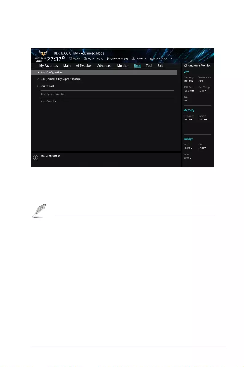
PRIME/PRO/TUF GAMING X570 Series BIOS Manual 41
1.8 Boot menu
The Boot menu items allow you to change the system boot options.
Boot Conguration
Fast Boot
[Disabled] Allows your system to go back to its normal boot speed.
[Enabled] Allows your system to accelerate the boot speed.
The following items appear only when you set the Fast Boot to [Enabled].
Next Boot after AC Power Loss
[Normal Boot] Returns to normal boot on the next boot after an AC power
loss.
[Fast Boot] Accelerates the boot speed on the next boot after an AC
power loss.
Boot Logo Display
[Auto] Sets the boot logo to display during POST.
[Full Screen] Sets the boot logo display in full screen during POST.
[Disabled] Disables the boot logo display during POST.

42 PRIME/PRO/TUF GAMING X570 Series BIOS Manual
The following item appears only when you set the Boot Logo Display to [Auto] and [Full
Screen].
Post Delay Time
This item allows you to select a desired additional POST waiting time to
easily enter the BIOS Setup. You can only execute the POST delay time
during normal boot.
Conguration options: [0 sec] — [10 sec]
This feature only works when set under normal boot.
The following item appears only when you set the Boot Logo Display to [Disabled].
Post Report
This item allows you to select a desired POST report waiting time.
Conguration options: [1 sec] — [10 sec] [Until Press ESC]
Boot up NumLock State
This item allows you to enable or disable power-on state of the NumLock.
Conguration options: [On] [Off]
Wait For ‘F1’ If Error
This item allows your system to wait for the <F1> key to be pressed when error occurs.
Conguration options: [Disabled] [Enabled]
Option ROM Messages
[Force BIOS] The third-party ROM messages will be forced to display during the boot
sequence.
[Keep Current] The third-party ROM messages will be displayed only if the third-party
manufacturer had set the add-on device to do so.
Interrupt 19 Capture
[Enabled] Execute the trap right away.
[Disabled] Execute the trap during legacy boot.
AMI Native NVMe Driver Support
This item allows you to enable or disable all NVMe device native OpROM.
Conguration options: [On] [Off]
Setup Mode
[Advanced Mode] This item allows you to go to Advanced Mode of the BIOS after POST.
[EZ Mode] This item allows you to go to EZ Mode of the BIOS after POST.

PRIME/PRO/TUF GAMING X570 Series BIOS Manual 43
CSM (Compatibility Support Module)
This item allows you to congure the CSM (Compatibility Support Module) items to fully
support the various VGA, bootable devices and add-on devices for better compatibility.
Launch CSM
[Enabled] For better compatibility, enable the CSM to fully support the non-UEFI
driver add-on devices or the Windows® UEFI mode.
[Disabled] Disable the CSM to fully support the non-UEFI driver add-on devices
or the Windows® UEFI mode.
The following items appear only when you set the Launch CSM to [Enabled].
Boot Device Control
This item allows you to select the type of devices that you want to boot.
Conguration options: [UEFI and Legacy OPROM] [Legacy OPROM only]
[UEFI only]
Boot from Network Devices
This item allows you to select the type of network devices that you want to
launch.
Conguration options: [Ignore] [Legacy only] [UEFI only]
Boot from Storage Devices
This item allows you to select the type of storage devices that you want to
launch.
Conguration options: [Ignore] [Legacy only] [UEFI driver rst]
Boot from PCI-E Expansion Devices
This item allows you to select the type of PCI-E expansion devices that you
want to launch.
Conguration options: [Ignore] [Legacy only] [UEFI only]
Secure Boot
This item allows you to congure the Windows® Secure Boot settings and manage its keys to
protect the system from unauthorized access and malwares during POST.
OS Type
[Windows UEFI
Mode]
This item allows you to select your installed operating system.
Execute the Microsoft® Secure Boot check. Only select
this option when booting on Windows® UEFI mode or other
Microsoft® Secure Boot compliant OS.
[Other OS] Get the optimized function when booting on Windows® non-
UEFI mode. Microsoft® Secure Boot only supports Windows®
UEFI mode.

44 PRIME/PRO/TUF GAMING X570 Series BIOS Manual
Key Management
Clear Secure Boot keys
This item appears only when you load the default Secure Boot keys. This item allows
you to clear all default Secure Boot keys.
Save all Secure Boot variables
This item allows you to save all the Secure Boot keys to a USB storage device.
PK Management
The Platform Key (PK) locks and secures the rmware from any permissible changes.
The system veries the PK before your system enters the OS.
Save to le
This item allows you to save the PK to a USB storage device.
Set New key
This item allows you to load the downloaded PK from a USB storage
device.
Delete key
This item allows you to delete the PK from your system. Once the PK is
deleted, all the system’s Secure Boot keys will not be active.
Conguration options: [Yes] [No]
The PK le must be formatted as a UEFI variable structure with time-based authenticated
variable.
KEK Management
The Key Exchange Keys (KEK) manages the Signature database (db) and Forbidden
Signature database (dbx).
Key Exchange Keys (KEK) refers to Microsoft® Secure Boot Key-Enrollment Key (KEK).
Save to le
This item allows you to save the KEK to a USB storage device.
Set New key
This item allows you to load the downloaded KEK from a USB storage
device.
Append Key
This item allows you to load the additional KEK from a storage device for
an additional db and dbx loaded management.

PRIME/PRO/TUF GAMING X570 Series BIOS Manual 45
Delete key
This item allows you to delete the KEK from your system.
Conguration options: [Yes] [No]
The KEK le must be formatted as a UEFI variable structure with time-based authenticated
variable.
DB Management
The Authorized Signatures (db) lists the signers or images of UEFI applications,
operating system loaders, and UEFI drivers that you can load on the single computer.
Save to le
This item allows you to save the db to a USB storage device.
Set New key
This item allows you to load the downloaded db from a USB storage
device.
Append Key
This item allows you to load the additional db from a storage device for an
additional db and dbx loaded management.
Delete key
This item allows you to delete the db le from your system.
Conguration options: [Yes] [No]
The db le must be formatted as a UEFI variable structure with time-based authenticated
variable.
DBX Management
The Forbidden Signature database (dbx) lists the forbidden images of db items that are
no longer trusted and cannot be loaded.
Save to le
This item allows you to save the dbx to a USB storage device.
Set New key
This item allows you to load the downloaded dbx from a USB storage
device.
Append Key
This item allows you to load the additional dbx from a storage device for an
additional db and dbx loaded management.
Delete key
This item allows you to delete the dbx le from your system.
Conguration options: [Yes] [No]
The dbx le must be formatted as a UEFI variable structure with time-based authenticated
variable.
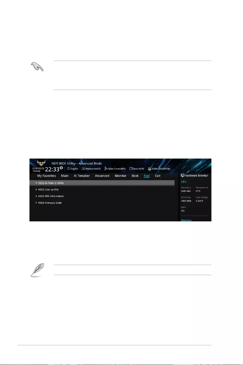
46 PRIME/PRO/TUF GAMING X570 Series BIOS Manual
1.9 Tool menu
The Tool menu items allow you to congure options for special functions. Select an item then
press <Enter> to display the submenu.
Boot Option Priorities
These items specify the boot device priority sequence from the available devices. The
number of device items that appears on the screen depends on the number of devices
installed in the system.
• To access Windows® OS in Safe Mode, press <F8 > after POST (Windows® 8 not
supported).
• To select the boot device during system startup, press <F8> when ASUS Logo
appears.
Boot Override
These item displays the available devices. The number of device items that appear on the
screen depends on the number of devices installed in the system. Click an item to start
booting from the selected device.
1.9.1 ASUS EZ Flash 3 Utility
This item allows you to run ASUS EZ Flash 3. When you press <Enter>, a conrmation
message appears. Use the left/right arrow key to select between [Yes] or [No], then press
<Enter> to conrm your choice.
For more details, refer to section 1.11.2 ASUS EZ Flash 3.
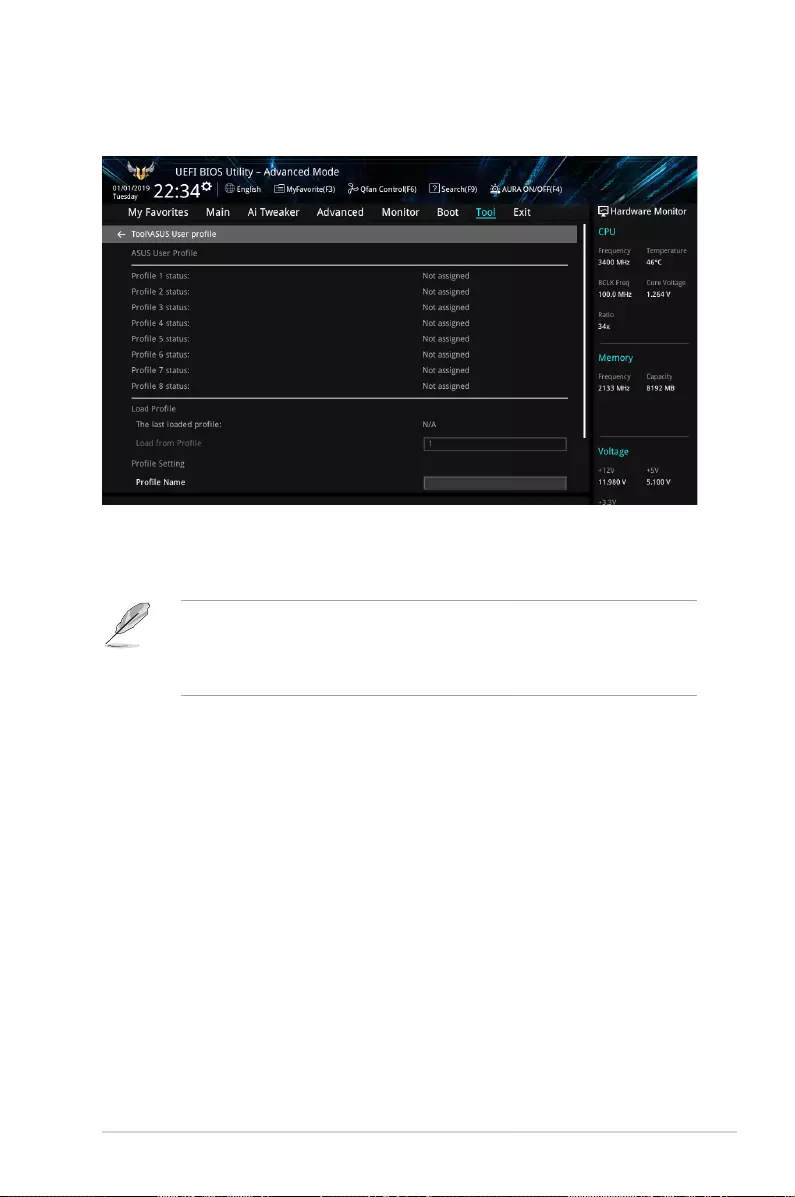
PRIME/PRO/TUF GAMING X570 Series BIOS Manual 47
1.9.2 ASUS User Prole
This item allows you to store or load multiple BIOS settings.
Load from Prole
This item allows you to load the previous BIOS settings saved in the BIOS Flash. Key in the
prole number that saved your BIOS settings, press <Enter>, and then select Yes.
• DO NOT shut down or reset the system while updating the BIOS to prevent the
system boot failure!
• We recommend that you update the BIOS le only coming from the same memory/
CPU conguration and BIOS version.
Prole Name
This item allows you to key in a prole name.
Save to Prole
This item allows you to save the current BIOS settings to the BIOS Flash, and create a
prole. Key in a prole number from one to eight, press <Enter>, and then select Yes.
Load/Save Prole from/to USB Drive
This item allows you to load or save prole from your USB drive, load and save prole to your
USB drive.
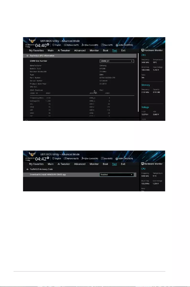
48 PRIME/PRO/TUF GAMING X570 Series BIOS Manual
1.9.3 ASUS SPD Information
This item allows you to view the DRAM SPD information.
1.9.4 ASUS Armoury Crate
This item allows you to enable Armoury Crate download process.
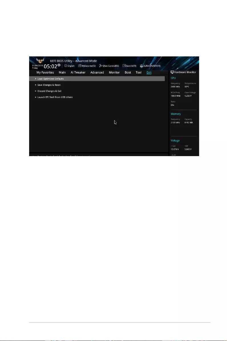
PRIME/PRO/TUF GAMING X570 Series BIOS Manual 49
1.10 Exit menu
The Exit menu items allow you to load the optimal default values for the BIOS items, and
save or discard your changes to the BIOS items. You can access the EZ Mode from the Exit
menu.
Load Optimized Defaults
This option allows you to load the default values for each of the parameters on the Setup
menus. When you select this option or if you press <F5>, a conrmation window appears.
Select OK to load the default values.
Save Changes & Reset
Once you are nished making your selections, choose this option from the Exit menu to
ensure the values you selected are saved. When you select this option or if you press <F10>,
a conrmation window appears. Select OK to save changes and exit.
Discard Changes & Exit
This option allows you to exit the Setup program without saving your changes. When you
select this option or if you press <Esc>, a conrmation window appears. Select Yes to
discard changes and exit.
Launch EFI Shell from USB drives
This option allows you to attempt to launch the EFI Shell application (shellx64.e) from one of
the available lesystem devices.

50 PRIME/PRO/TUF GAMING X570 Series BIOS Manual
1.11 Updating BIOS
The ASUS website publishes the latest BIOS versions to provide enhancements on system
stability, compatibility,and performance. However, BIOS updating is potentially risky. If
there is no problem using the current version of BIOS, DO NOT manually update the BIOS.
Inappropriate BIOS updating may result to system’s failure to boot. Carefully follow the
instructions in this chapter to update your BIOS when necessary.
Visit http://www.asus.com to download the latest BIOS le for this motherboard.
The following utilities allow you to manage and update the motherboard BIOS setup program.
1. EZ Update: Updates the BIOS in Windows® environment.
2. ASUS EZ Flash 3: Updates the BIOS using a USB ash drive.
3. ASUS CrashFree BIOS 3: Restores the BIOS using the motherboard support DVD or a
USB ash drive when the BIOS le fails or gets corrupted.
1.11.1 EZ Update
The EZ Update is a utility that allows you to update the motherboard BIOS in Windows®
environment.
• EZ Update requires an Internet connection either through a network or an ISP
(Internet Service Provider).
• This utility is available in the support DVD that comes with the motherboard package.
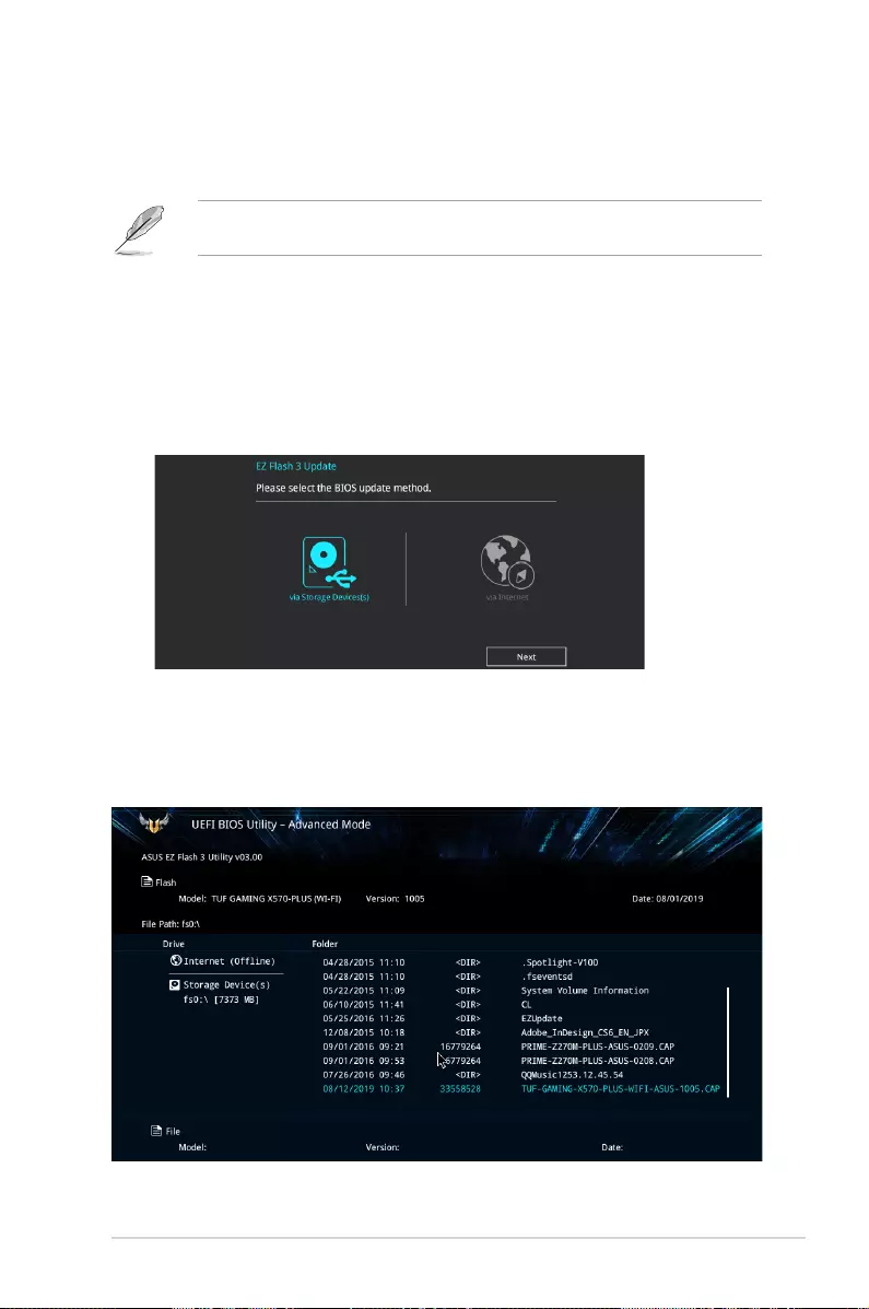
PRIME/PRO/TUF GAMING X570 Series BIOS Manual 51
1.11.2 ASUS EZ Flash 3
ASUS EZ Flash 3 allows you to download and update to the latest BIOS through the Internet
without having to use a bootable oppy disk or an OS-based utility.
Updating through the Internet varies per region and Internet conditions. Check your local
Internet connection before updating through the Internet.
To update the BIOS by USB:
1. Enter the Advanced Mode of the BIOS setup program. Go to the Tool menu to select
ASUS EZ Flash 3 Utility and press <Enter>.
2. Insert the USB ash disk that contains the latest BIOS le to the USB port.
3. Select via Storage Device(s).
4. Press the Up/Down arrow keys to nd the USB ash disk that contains the latest BIOS,
and then press <Enter>.
5. Press the Up/Down arrow keys to nd the BIOS le, and then press <Enter> to perform
the BIOS update process. Reboot the system when the update process is done.
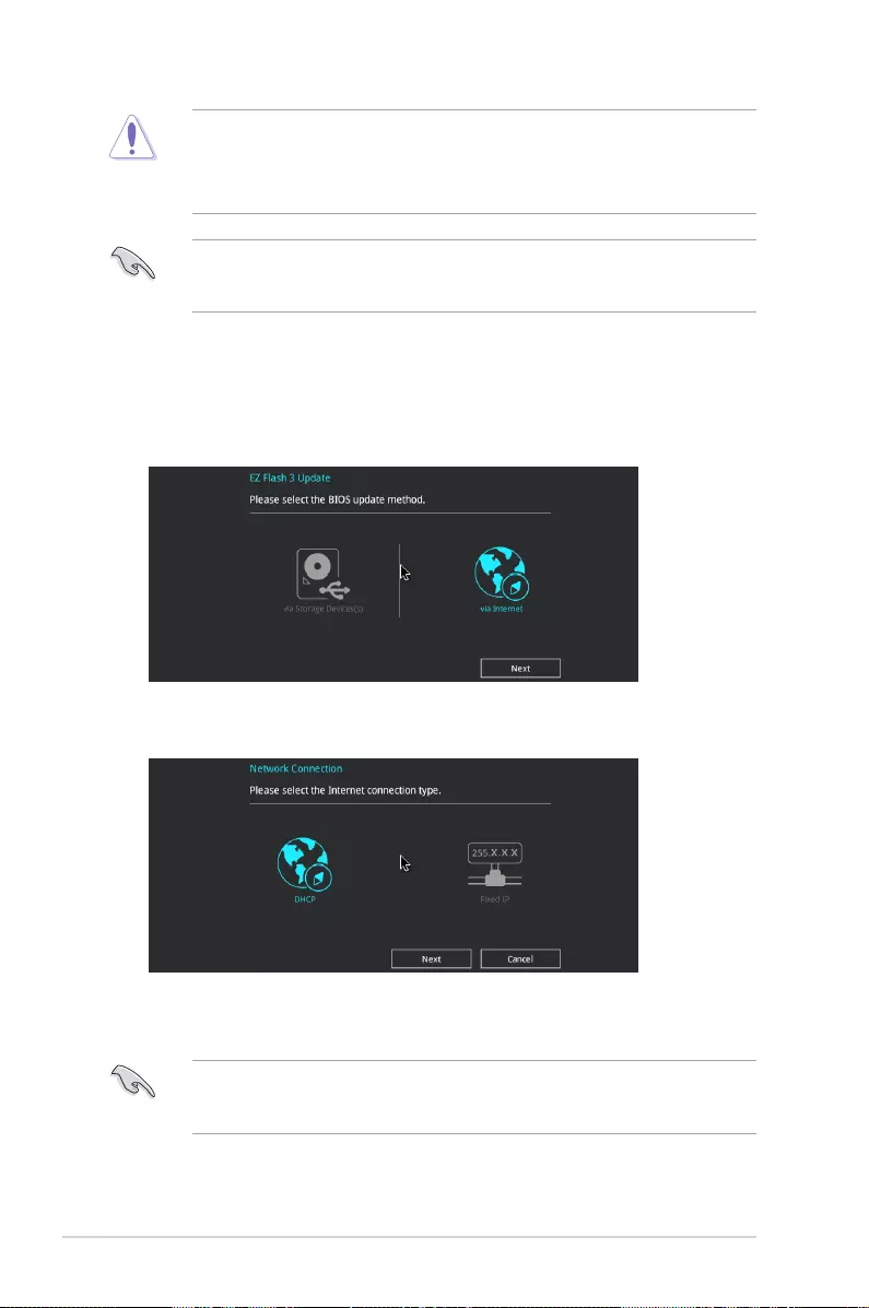
52 PRIME/PRO/TUF GAMING X570 Series BIOS Manual
• This function can support devices such as a USB ash disk with FAT 32/16 format and
single partition only.
• DO NOT shut down or reset the system while updating the BIOS to prevent system
boot failure!
Ensure to load the BIOS default settings to ensure system compatibility and stability. Select
the Load Optimized Defaults item under the Exit menu. See section 1.10 Exit Menu for
details.
To update the BIOS by Internet:
1. Enter the Advanced Mode of the BIOS setup program. Go to the Tool menu to select
ASUS EZ Flash 3 Utility and press <Enter>.
2. Select via Internet.
3. Press the Left/Right arrow keys to select an Internet connection method, and then
press <Enter>.
Ensure to load the BIOS default settings to ensure system compatibility and stability. Select
the Load Optimized Defaults item under the Exit menu. See section 1.10 Exit Menu for
details.
4. Follow the onscreen instructions to complete the update.
5. Reboot the system when the update process is done.

PRIME/PRO/TUF GAMING X570 Series BIOS Manual 53
1.11.3 ASUS CrashFree BIOS 3
The ASUS CrashFree BIOS 3 utility is an auto recovery tool that allows you to restore the
BIOS le when it fails or gets corrupted during the updating process. You can restore a
corrupted BIOS le using the motherboard support DVD or a USB ash drive that contains
the BIOS le.
The BIOS le in the motherboard support DVD may be older than the BIOS le published
on the ASUS ofcial website. If you want to use the newer BIOS le, download the le at
https://www.asus.com/support/ and save it to a USB ash drive.
Recovering the BIOS
To recover the BIOS:
1. Turn on the system.
2. Insert the motherboard support DVD to the optical drive, or the USB ash drive
containing the BIOS le to the USB port.
3. The utility automatically checks the devices for the BIOS le. When found, the utility
reads the BIOS le and enters ASUS EZ Flash 3 automatically.
4. The system requires you to enter BIOS Setup to recover the BIOS setting. To ensure
system compatibility and stability, we recommend that you press <F5> to load default
BIOS values.
DO NOT shut down or reset the system while updating the BIOS! Doing so can cause
system boot failure!

54 PRIME/PRO/TUF GAMING X570 Series BIOS Manual