- Manuals
- Brands
- Asus Manuals
- Motherboard
- TUF B360-PRO GAMING
- Manual
-
Contents
-
Table of Contents
-
Bookmarks
Quick Links
Related Manuals for Asus TUF B360-PRO GAMING
Summary of Contents for Asus TUF B360-PRO GAMING
-
Page 1
TUF B360-PRO GAMING… -
Page 2
Product warranty or service will not be extended if: (1) the product is repaired, modified or altered, unless such repair, modification of alteration is authorized in writing by ASUS; or (2) the serial number of the product is defaced or missing. -
Page 3: Table Of Contents
Contents Safety information …………………. iv About this guide ………………….iv Package contents ………………….. vi ASUS TUF B360-PRO GAMING specifications summary ……..vi Chapter 1: Product Introduction Before you proceed ………………. 1-1 Motherboard overview …………….1-1 Central Processing Unit (CPU) …………..1-9 System memory ………………
-
Page 4: Safety Information
Safety information Electrical safety • To prevent electrical shock hazard, disconnect the power cable from the electrical outlet before relocating the system. • When adding or removing devices to or from the system, ensure that the power cables for the devices are unplugged before the signal cables are connected. If possible, disconnect all power cables from the existing system before you add a device.
-
Page 5: Conventions Used In This Guide
Refer to the following sources for additional information and for product and software updates. ASUS website The ASUS website (www.asus.com) provides updated information on ASUS hardware and software products. Optional documentation Your product package may include optional documentation, such as warranty flyers, that may have been added by your dealer.
-
Page 6: Package Contents
* DDR4 2666 MHz and higher memory modules will run at max. 2666 MHz on Intel ® Gen 6-core or higher processors. ** Refer to www.asus.com for the latest Memory QVL (Qualified Vendors List). 1 x PCIe 3.0/2.0 x16 slot Expansion 1 x PCIe 3.0/2.0 x16 slot (max.
-
Page 7
— ASUS ESD Guard: Enhanced ESD protection Gaming — ASUS Overvoltage Protection: World-class circuit-protecting power design Features — ASUS Stainless-Steel Back I/O: 3X corrosion-resistance for greater durability! — ASUS DIGI+ VRM: 4+2 Phase digital power design ASUS SafeSlot Exclusive DTS Custom for GAMING Headsets… -
Page 8
— ASUS CrashFree BIOS 3 — ASUS EZ Flash 3 File Transfer — Cloud GO! — File Transfer Q-Design — ASUS Q-LED (CPU, DRAM, VGA, Boot Device LED) — ASUS Q-Slot — ASUS Q-DIMM ASUS Quiet — ASUS Fan Xpert 4 Core Thermal — Stylish Fanless Design: PCH Heat-sink &… -
Page 9
1 x Clear CMOS jumper 128 Mb Flash ROM, UEFI AMI BIOS, PnP, DMI3.0, WfM2.0, SM BIOS 3.1, ACPI 6.1, Multi-language BIOS, ASUS EZ Flash 3, CrashFree BIOS 3, F6 Qfan BIOS Control, F3 My Favorites, F4 AURA ON/OFF, F9 Search, Last Modified log, F12 PrintScreen, and ASUS DRAM SPD (Serial Presence Detect) memory information WfM 2.0, DMI 3.0, WOL by PME, PXE… -
Page 11: Chapter 1: Product Introduction
Failure to do so may cause severe damage to the motherboard, peripherals, or components. Motherboard overview Place this side towards the rear of the chassis Unplug the power cord before installing or removing the motherboard. Failure to do so can cause you physical injury and damage motherboard components. ASUS TUF B360-PRO GAMING…
-
Page 12: Layout Contents
1.2.1 Layout contents Connectors/Jumpers/Slots Page ATX power connectors (24-pin EATXPWR, 8-pin EATX12V) Intel LGA1151 CPU socket ® CPU, chassis, and AIO pump fan connectors (4-pin CPU_FAN, 4-pin CHA_FAN1~2, 4-pin AIO_PUMP FAN) DDR4 DIMM slots USB 3.1 Gen 1 connector (20-1 pin U31G1_56) M.2 sockets (M.2_1; M.2_2) Intel B360 Serial ATA 6.0 Gb/s connector (7-pin SATA6G_1~6) ® System panel connector (20-3 pin PANEL) Clear RTC RAM (2-pin CLRTC) 10. USB 2.0 connector (10-1 pin USB1114) 11. AURA RGB header (4-pin RGB_HEADER) 12. Serial port connector (10-1 pin COM) 13. Front panel audio connector (10-1 pin AAFP) 14. Digital audio connector (4-1 pin SPDIF_OUT) 15. PCI Express 3.0/2.0 x1 slots 16. PCI Express 3.0/2.0 x16 slots ATX power connectors (24-pin EATXPWR, 8-pin EATX12V) EATX12V Correctly orient the ATX power supply plugs into these connectors and push down firmly until the connectors…
-
Page 13
DIMM sockets. For more details, refer to 1.4 System memory. USB 3.1 Gen 1 connector (20-1 pin U31G1_56) U31G1_56 Connect a USB 3.1 Gen 1 module to any of these PIN 1 USB3+5V connectors for additional USB 3.1 Gen 1 front or rear USB3+5V IntA_P1_SSRX- IntA_P2_SSRX- IntA_P1_SSRX+ panel ports. These connectors comply with USB 3.1 IntA_P2_SSRX+ IntA_P1_SSTX- Gen 1 specifications and provides faster data transfer IntA_P2_SSTX- IntA_P1_SSTX+ IntA_P2_SSTX+ IntA_P1_D- speeds of up to 5 Gbps, faster charging time for USB- IntA_P2_D- IntA_P1_D+ IntA_P2_D+ chargeable devices, optimized power efficiency, and backward compatibility with USB 2.0 ASUS TUF B360-PRO GAMING… -
Page 14
M.2 sockets (M.2_1; M.2_2) M.2(SOCKET3) These sockets allow you to install M.2 (NGFF) SSD modules. • The M.2_1 socket supports M Key and 2242/2260/2280 storage devices (both SATA & PCIE x2 mode), and supports data transfer speed of up to 16Gb/s. • The M.2_2 socket supports M Key and 2242/2260/2280/22110 storage devices (PCIE x4 mode), and supports data transfer speed of up to 32Gb/s. • When a device in SATA mode is installed on the M.2_1 socket, SATA_2 port cannot be used. Intel B360 Serial ATA 6.0Gb/s connectors (7-pin ® SATA6G SATA6G_1-6) These connectors connect to Serial ATA 6.0 Gb/s hard RSATA_TXP RSATA_TXN disk drives via Serial ATA 6.0 Gb/s signal cables. RSATA_RXN RSATA_RXP System panel connector (20-3 pin PANEL) This connector supports several chassis-mounted functions. -
Page 15
This USB connectors comply with USB 2.0 specifications and supports up to 480Mbps connection speed. PIN 1 PIN 1 AURA RGB header (4-pin RGB_HEADER) These connectors are for RGB LED strips. Serial port connector (10-1 pin COM) This connector is for a serial (COM) port. Connect the serial port module cable to this connector, then install the module to a slot opening at the back of the system chassis. PIN 1 ASUS TUF B360-PRO GAMING… -
Page 16
Front panel audio connector (10-1 pin AAFP) This connector is for a chassis-mounted front panel audio I/O module that supports HD Audio standard. Connect one end of the front panel audio I/O module AAFP cable to this connector. HD-audio-compliant pin definition Digital audio connector (4-1 pin SPDIF_OUT) This connector is for an additional Sony/Philips Digital Interface (S/PDIF) port. Connect the S/PDIF Out module cable to this connector, then install the module to a slot opening at the back of the system chassis. SPDIF_OUT We recommend that you connect a high-definition front panel audio module to this connector to avail of the motherboard’s high-definition audio capability. -
Page 17: Rear Panel Connectors
Microphone port (pink). This port connects to a microphone. Refer to the audio configuration table for the function of the audio ports in 2, 4, 5.1, or 7.1-channel configuration. Audio 2, 4, 5.1, or 7.1-channel configuration Headset Port 4-channel 5.1-channel 7.1-channel 2-channel Light Blue (Rear panel) Line In Rear Speaker Out Rear Speaker Out Rear Speaker Out Lime (Rear panel) Line Out Front Speaker Out Front Speaker Out Front Speaker Out Pink (Rear panel) Mic In Mic In Bass/Center Bass/Center Lime (Front panel) Side Speaker Out ASUS TUF B360-PRO GAMING…
-
Page 18
To configure a 7.1-channel audio output: Use a chassis with HD audio module in the front panel to support a 7.1-channel audio output. USB 2.0 ports. These 4-pin Universal Serial Bus (USB) ports are for USB 2.0/1.1 devices. USB 3.1 Gen 2 Type-A ports. These 9-pin Universal Serial Bus 3.1 (USB 3.1) ports are for USB 3.1 Gen 2 devices. • Due to the limitation of USB 3.1 Gen 2 and USB 3.1 Gen 1 controller, USB 3.1 Gen 2 and USB 3.1 Gen 1 devices can only be used under Windows OS environment and after the USB 3.1 Gen 2 and USB 3.1 Gen 1 driver installation. • We strongly recommend that you connect USB 3.1 Gen 2 and USB 3.1 Gen 1 devices to USB 3.1 Gen 2 and USB 3.1 Gen 1 ports for faster and better performance from your USB 3.1 Gen 2 and USB 3.1 Gen 1 devices. USB 3.1 Gen 1 Type-C™ port. This 24-pin Universal Serial Bus (USB) port is for USB (Type C) devices. HDMI port. This port is for a High-Definition Multimedia Interface (HDMI) connector, and is HDCP compliant allowing playback of HD DVD, Blu-ray, and other protected content. D-sub port. This port is for a VGA monitor or other VGA compatible devices. USB 2.0 ports. These 4-pin Universal Serial Bus (USB) ports are for USB 2.0/1.1 devices. -
Page 19: Central Processing Unit (Cpu)
This motherboard comes with a surface mount LGA1151 socket designed for the 8th Generation Intel Core™ i7 / Core™ i5 / Core™ i3, ® Pentium and Celeron processors. ® ® Unplug all power cables before installing the CPU. • Ensure that you install the correct CPU designed for the LGA1151 socket only. DO NOT install a CPU designed for LGA1150, LGA1155 and LGA1156 sockets on the LGA1151 socket. • Upon purchase of the motherboard, ensure that the PnP cap is on the socket and the socket contacts are not bent. Contact your retailer immediately if the PnP cap is missing, or if you see any damage to the PnP cap/socket contacts/motherboard components. • Keep the cap after installing the motherboard. ASUS will process Return Merchandise Authorization (RMA) requests only if the motherboard comes with the cap on the LGA1151 socket. • The product warranty does not cover damage to the socket contacts resulting from incorrect CPU installation/removal, or misplacement/loss/incorrect removal of the PnP cap. Installing the CPU Apply the Thermal Interface Material to the CPU heatsink and CPU before you install the heatsink and fan if necessary. ASUS TUF B360-PRO GAMING…
-
Page 20: System Memory
Channel A DIMM_A1 & DIMM_A2 Channel B DIMM_B1 & DIMM_B2 • You may install varying memory sizes in Channel A and Channel B. The system maps the total size of the lower-sized channel for the dual-channel configuration. Any excess memory from the higher-sized channel is then mapped for single-channel operation. • Always install DIMMs with the same CAS latency. For optimal compatibility, we recommend that you install memory modules of the same version or date code (D/C) from the same vendor. Check with the retailer to get the correct memory modules. • According to Intel CPU spec, DIMM voltage below 1.35V is recommended to protect ® the CPU. • Due to Intel chipset limitation, DDR4 2666MHz and higher memory modules will run ® at max. 2666MHz on Intel 8th Gen. 6-core or higher processors. ® • The default memory operation frequency is dependent on its Serial Presence Detect (SPD), which is the standard way of accessing information from a memory module. Under the default state, some memory modules for overclocking may operate at a lower frequency than the vendor-marked value. • For system stability, use a more efficient memory cooling system to support a full memory load (4 DIMMs). • Refer to www.asus.com for the latest Memory QVL (Qualified Vendors List) 1-10 Chapter 1: Product Introduction…
-
Page 21: Installing A Dimm
Installing a DIMM To remove a DIMM ASUS TUF B360-PRO GAMING 1-11…
-
Page 22
1-12 Chapter 1: Product Introduction… -
Page 23: Chapter 2: Bios Information
Managing and updating your BIOS Save a copy of the original motherboard BIOS file to a USB flash disk in case you need to restore the BIOS in the future. Copy the original motherboard BIOS using the ASUS Update utility.
-
Page 24: Asus Ez Flash
2.1.2 ASUS EZ Flash 3 The ASUS EZ Flash 3 allows you to download and update to the latest BIOS through the Internet without having to use a bootable floppy disk or an OS‑based utility. • Ensure to load the BIOS default settings to ensure system compatibility and stability.
-
Page 25: Asus Crashfree Bios 3 Utility
2.1.3 ASUS CrashFree BIOS 3 utility The ASUS CrashFree BIOS 3 is an auto recovery tool that allows you to restore the BIOS file when it fails or gets corrupted during the updating process. You can restore a corrupted BIOS file using the motherboard support DVD or a USB flash drive that contains the updated BIOS file.
-
Page 26
ENTER to select boot device ESC to boot using defaults P2: ST3808110AS (76319MB) aigo miniking (250MB) UEFI: (FAT) ASUS DRW-2014L1T(4458MB) P1: ASUS DRW-2014L1T(4458MB) UEFI: (FAT) aigo miniking (250MB) Enter Setup When the booting message appears, press <Enter> within five (5) seconds to enter FreeDOS prompt. -
Page 27
DO NOT shut down or reset the system while updating the BIOS to prevent system boot failure. Ensure to load the BIOS default settings to ensure system compatibility and stability. Select the Load Optimized Defaults item under the Exit BIOS menu. See section 2.3 Exit Menu for details. ASUS TUF B360-PRO GAMING 2‑5… -
Page 28: Bios Setup Program
The BIOS setup screens shown in this section are for reference purposes only, and may not exactly match what you see on your screen. • Visit the ASUS website at www.asus.com to download the latest BIOS file for this motherboard. •…
-
Page 29
Click to go to Advanced mode Loads optimized Search on the FAQ default settings Click to display boot devices Selects the boot device priority The boot device options vary depending on the devices you installed to the system. ASUS TUF B360-PRO GAMING 2‑7… -
Page 30: Advanced Mode
2.2.2 Advanced Mode The Advanced Mode provides advanced options for experienced end‑users to configure the BIOS settings. The figure below shows an example of the Advanced Mode. Refer to the following sections for the detailed configurations. To access the EZ Mode, click EzMode(F7) or press <F7>. Search(F9) Configuration fields Scroll bar…
-
Page 31: Menu Bar
AURA (F4) This button allows you to turn the RGB LED lighting or functional LED on or off. [ON] All AURA effects will be enabled. (Default mode) [OFF] All AURA effects will be disabled. ASUS TUF B360-PRO GAMING…
-
Page 32: Scroll Bar
Move your mouse over this button to show a QR code, scan this QR code on your mobile device to connect to the BIOS FAQ web page of the ASUS support website. You can also scan the following QR code:…
-
Page 33: Exit Menu
<Esc>, a confirmation window appears. Select OK to discard changes and exit. Launch EFI Shell from USB drives This option allows you to attempt to launch the EFI Shell application (shellx64.efi) from one of the available USB devices. ASUS TUF B360-PRO GAMING 2-11…
-
Page 34
2-12 Chapter 2: BIOS Information… -
Page 35: Appendix
Consult the dealer or an experienced radio/TV technician for help. The use of shielded cables for connection of the monitor to the graphics card is required to assure compliance with FCC regulations. Changes or modifications to this unit not expressly approved by the party responsible for compliance could void the user’s authority to operate this equipment. ASUS TUF B360-PRO GAMING…
-
Page 36
Compliance Statement of Innovation, Science and Economic Development Canada (ISED) This device complies with Innovation, Science and Economic Development Canada licence exempt RSS standard(s). Operation is subject to the following two conditions: (1) this device may not cause interference, and (2) this device must accept any interference, including interference that may cause undesired operation of the device. -
Page 37
ASUS Recycling/Takeback Services ASUS recycling and takeback programs come from our commitment to the highest standards for protecting our environment. We believe in providing solutions for you to be able to responsibly recycle our products, batteries, other components as well as the packaging materials. -
Page 38
доступний на: www.asus.com/support Cijeli tekst EU izjave o sukladnosti dostupan je na: www.asus.com/support Türkçe AsusTek Computer Inc., bu aygıtın temel gereksinimlerle ve ilişkili Čeština Společnost ASUSTeK Computer Inc. tímto prohlašuje, že toto Yönergelerin diğer ilgili koşullarıyla uyumlu olduğunu beyan eder. -
Page 39: Asus Contact Information
+1-510-608-4555 Web site https://www.asus.com/us/ Technical Support Support fax +1-812-284-0883 Telephone +1-812-282-2787 Online support https://www.asus.com/support/Product/ContactUs/ Services/questionform/?lang=en-us ASUS COMPUTER GmbH (Germany and Austria) Address Harkort Str. 21-23, 40880 Ratingen, Germany +49-2102-959931 Web site https://www.asus.com/de/ Technical Support Telephone +49-2102-5789555 Support Fax +49-2102-959911 Online support https://www.asus.com/support/Product/ContactUs/…
-
Page 40: Declaration Of Conformity
800 Corporate Way, Fremont Phone/Fax No: (510)739-3777/(510)608-4555 hereby declares that the product Product Name : Motherboard Model Number : TUF H370-PRO GAMING, TUF B360-PRO GAMING, TUF B360-PLUS GAMING Conforms to the following specifications: FCC Part 15, Subpart B, Unintentional Radiators Supplementary Information: This device complies with part 15 of the FCC Rules.
Посмотреть инструкция для Asus TUF B360-Pro Gaming WIFI бесплатно. Руководство относится к категории материнские платы, 1 человек(а) дали ему среднюю оценку 8.4. Руководство доступно на следующих языках: английский. У вас есть вопрос о Asus TUF B360-Pro Gaming WIFI или вам нужна помощь? Задайте свой вопрос здесь
Не можете найти ответ на свой вопрос в руководстве? Вы можете найти ответ на свой вопрос ниже, в разделе часто задаваемых вопросов о Asus TUF B360-Pro Gaming WIFI.
Какая ширина Asus TUF B360-Pro Gaming WIFI?
Asus TUF B360-Pro Gaming WIFI имеет ширину 305 mm.
Какая толщина Asus TUF B360-Pro Gaming WIFI?
Asus TUF B360-Pro Gaming WIFI имеет толщину 244 mm.
Инструкция Asus TUF B360-Pro Gaming WIFI доступно в русский?
К сожалению, у нас нет руководства для Asus TUF B360-Pro Gaming WIFI, доступного в русский. Это руководство доступно в английский.
Не нашли свой вопрос? Задайте свой вопрос здесь
![]()
TUF B360-PRO GAMING
Motherboard

E13810
First Edition
February 2018
Copyright © 2018 ASUSTeK COMPUTER INC. All Rights Reserved.
No part of this manual, including the products and software described in it, may be reproduced, transmitted, transcribed, stored in a retrieval system, or translated into any language in any form or by any means, except documentation kept by the purchaser for backup purposes, without the express written permission of ASUSTeK COMPUTER INC. (“ASUS”).
Product warranty or service will not be extended if: (1) the product is repaired, modified or altered, unless such repair, modification of alteration is authorized in writing by ASUS; or (2) the serial number of the product is defaced or missing.
ASUS PROVIDES THIS MANUAL “AS IS” WITHOUT WARRANTY OF ANY KIND, EITHER EXPRESS OR IMPLIED, INCLUDING BUT NOT LIMITED TO THE IMPLIED WARRANTIES OR CONDITIONS OF MERCHANTABILITY OR FITNESS FOR A PARTICULAR PURPOSE. IN NO EVENT SHALL ASUS, ITS DIRECTORS, OFFICERS, EMPLOYEES OR AGENTS BE LIABLE FOR ANY INDIRECT, SPECIAL, INCIDENTAL, OR CONSEQUENTIAL DAMAGES (INCLUDING DAMAGES FOR LOSS OF PROFITS, LOSS OF BUSINESS, LOSS OF USE OR DATA, INTERRUPTION OF BUSINESS AND THE LIKE), EVEN IF ASUS HAS BEEN ADVISED OF THE POSSIBILITY OF SUCH DAMAGES ARISING FROM ANY DEFECT OR ERROR IN THIS MANUAL OR PRODUCT.
SPECIFICATIONS AND INFORMATION CONTAINED IN THIS MANUAL ARE FURNISHED FOR INFORMATIONAL USE ONLY, AND ARE SUBJECT TO CHANGE AT ANY TIME WITHOUT NOTICE, AND SHOULD NOT BE CONSTRUED AS A COMMITMENT BY ASUS. ASUS ASSUMES NO RESPONSIBILITY OR LIABILITY FOR ANY ERRORS OR INACCURACIES THAT MAY APPEAR IN THIS MANUAL, INCLUDING THE PRODUCTS AND SOFTWARE DESCRIBED IN IT.
Products and corporate names appearing in this manual may or may not be registered trademarks or copyrights of their respective companies, and are used only for identification or explanation and to the owners’ benefit, without intent to infringe.
Offer to Provide Source Code of Certain Software
This product contains copyrighted software that is licensed under the General Public License (“GPL”), under the Lesser General Public License Version (“LGPL”) and/or other Free Open Source Software Licenses. Such software in this product is distributed without any warranty to the extent permitted by the applicable law. Copies of these licenses are included in this product.
Where the applicable license entitles you to the source code of such software and/or other additional data, you may obtain it for a period of three years after our last shipment of the product, either
(1)for free by downloading it from https://www.asus.com/support/
or
(2)for the cost of reproduction and shipment, which is dependent on the preferred carrier and the location where you want to have it shipped to, by sending a request to:
ASUSTeK Computer Inc.
Legal Compliance Dept.
15 Li Te Rd.,
Beitou, Taipei 112
Taiwan
In your request please provide the name, model number and version, as stated in the About Box of the product for which you wish to obtain the corresponding source code and your contact details so that we can coordinate the terms and cost of shipment with you.
The source code will be distributed WITHOUT ANY WARRANTY and licensed under the same license as the corresponding binary/object code.
This offer is valid to anyone in receipt of this information.
ASUSTeK is eager to duly provide complete source code as required under various Free Open Source Software licenses. If however you encounter any problems in obtaining the full corresponding source code we would be much obliged if you give us a notification to the email address gpl@asus.com, stating the product and describing the problem (please DO NOT send large attachments such as source code archives, etc. to this email address).
ii

Contents
|
Safety information………………………………………………………………………………………… |
iv |
|
About this guide……………………………………………………………………………………………. |
iv |
|
Package contents…………………………………………………………………………………………. |
vi |
|
ASUS TUF B360-PRO GAMING specifications summary…………………………………. |
vi |
|
Chapter 1: |
Product Introduction |
||
|
1.1 |
Before you proceed………………………………………………………………………… |
1-1 |
|
|
1.2 |
Motherboard overview……………………………………………………………………. |
1-1 |
|
|
1.3 |
Central Processing Unit (CPU)………………………………………………………… |
1-9 |
|
|
1.4 |
System memory……………………………………………………………………………. |
1-10 |
|
Chapter 2: |
BIOS Information |
||
|
2.1 |
Managing and updating your BIOS |
…………………………………………………..2-1 |
|
|
2.2 |
BIOS setup program……………………………………………………………………….. |
2-6 |
|
|
2.3 |
Exit menu |
……………………………………………………………………………………… |
2-11 |
|
Appendix |
|||
|
Notices |
……………………………………………………………………………………………………… |
A-1 |
iii

Safety information
Electrical safety
•To prevent electrical shock hazard, disconnect the power cable from the electrical outlet before relocating the system.
•When adding or removing devices to or from the system, ensure that the power cables for the devices are unplugged before the signal cables are connected. If possible, disconnect all power cables from the existing system before you add a device.
•Before connecting or removing signal cables from the motherboard, ensure that all power cables are unplugged.
•Seek professional assistance before using an adapter or extension cord. These devices could interrupt the grounding circuit.
•Ensure that your power supply is set to the correct voltage in your area. If you are not sure about the voltage of the electrical outlet you are using, contact your local power company.
•If the power supply is broken, do not try to fix it by yourself. Contact a qualified service technician or your retailer.
Operation safety
•Before installing the motherboard and adding devices on it, carefully read all the manuals that came with the package.
•Before using the product, ensure all cables are correctly connected and the power cables are not damaged. If you detect any damage, contact your dealer immediately.
•To avoid short circuits, keep paper clips, screws, and staples away from connectors, slots, sockets and circuitry.
•Avoid dust, humidity, and temperature extremes. Do not place the product in any area where it may become wet.
•Place the product on a stable surface.
•If you encounter technical problems with the product, contact a qualified service technician or your retailer.
About this guide
This user guide contains the information you need when installing and configuring the motherboard.
How this guide is organized
This guide contains the following parts:
•Chapter 1: Product Introduction
This chapter describes the features of the motherboard and the new technology it supports. It includes descriptions of the switches, jumpers, and connectors on the motherboard.
•Chapter 2: BIOS Information
This chapter discusses changing system settings through the BIOS Setup menus.
iv
Where to find more information
Refer to the following sources for additional information and for product and software updates.
1.ASUS website
The ASUS website (www.asus.com) provides updated information on ASUS hardware and software products.
2.Optional documentation
Your product package may include optional documentation, such as warranty flyers, that may have been added by your dealer. These documents are not part of the standard package.
Conventions used in this guide
To ensure that you perform certain tasks properly, take note of the following symbols used throughout this manual.
DANGER/WARNING: Information to prevent injury to yourself when trying to complete a task.
CAUTION: Information to prevent damage to the components when trying to complete a task.
IMPORTANT: Instructions that you MUST follow to complete a task.
NOTE: Tips and additional information to help you complete a task.
Typography
|
Bold text |
Indicates a menu or an item to select. |
|
Italics |
Used to emphasize a word or a phrase. |
|
<Key> |
Keys enclosed in the less-than and greater-than sign |
|
means that you must press the enclosed key. |
|
|
Example: <Enter> means that you must press the Enter or |
|
|
Return key. |
|
|
<Key1> + <Key2> + <Key3> |
If you must press two or more keys simultaneously, the key |
|
names are linked with a plus sign (+). |
v

Package contents
Check your motherboard package for the following items.
|
Motherboard |
1 x ASUS TUF B360-PRO GAMING motherboard |
|
Cables |
2 x SATA 6 Gb/s cables |
|
1 x IO Shield |
|
|
Accessories |
2 x M.2 Screw Package |
|
1 x CPU Installation Tool |
|
|
Application DVD |
1 x Support DVD |
|
1 x User manual |
|
|
Documentation |
1 x TUF Certification card |
|
1 x TUF GAMING sticker |
If any of the above items is damaged or missing, contact your retailer.
ASUS TUF B360-PRO GAMING specifications summary
|
LGA1151 socket for 8th Gen Intel® Core™ Processor |
||
|
Supports 14nm CPU |
||
|
CPU |
Supports Intel® Turbo Boost Technology 2.0* |
|
|
* The Intel® Turbo Boost Technology 2.0 support depends on the CPU types. |
||
|
** Refer to www.asus.com for Intel® CPU support list. |
||
|
Chipset |
Intel® B360 Chipset |
|
|
4 x DIMM, max. 64GB, DDR4 2666/2400/2133 MHz, non-ECC, un-buffered |
||
|
memory |
||
|
Dual channel memory architecture |
||
|
Memory |
Supports Intel® Extreme Memory Profile (XMP) |
|
|
* DDR4 2666 MHz and higher memory modules will run at max. 2666 MHz on Intel® 8th |
||
|
Gen 6-core or higher processors. |
||
|
** Refer to www.asus.com for the latest Memory QVL (Qualified Vendors List). |
||
|
Expansion |
1 x PCIe 3.0/2.0 x16 slot |
|
|
1 x PCIe 3.0/2.0 x16 slot (max. at x4 mode) |
||
|
slots |
||
|
4 x PCIe 3.0/2.0 x1 slots |
||
|
Multi-GPU |
Supports AMD® 2-Way/Quad-GPU CrossFireX™ Technology |
|
|
support |
||
|
Integrated Graphics ProcessorIntel® HD Graphics support |
||
|
Multi-VGA output support: HDMI/D-sub ports |
||
|
— Supports HDMI 1.4b with max. resolution 4096 x 2160@24Hz / 2560 x |
||
|
VGA |
1600@60Hz |
|
|
— Supports D-sub with max. resolution 1920*1200@60Hz |
||
|
Supports Intel® InTru™ 3D/Quick Sync Video/Clear Video HD Technology/ |
||
|
Insider™ |
||
|
Maximum shared memory of 1024 MB (for iGPU exclusively) |
||
|
(continued on the next page) |
vi

ASUS TUF B360-PRO GAMING specifications summary
Intel® B360 Chipset
—1 x M.2_1 Socket 3 with M Key, type 2242/2260/2280 storage devices support (both SATA & PCIE x2 mode)*
—1 x M.2_2 Socket 3 with M Key, type 2242/2260/2280/22110 storage devices
|
Storage |
support (PCIE x4 mode) |
|
— 6 x SATA 6.0 Gb/s ports |
|
|
— Ready for Intel® Optane Memory |
|
|
* The M.2_1 socket shares SATA_2 port when using M.2 SATA mode devices. Adjust BIOS |
|
|
settings to use a SATA device. |
|
|
Intel® I219-V Gigabit LAN |
|
|
— Dual interconnect between the integrated Media Access Controller (MAC) and |
|
|
LAN |
physical layer (PHY) |
|
TUF LANGuard |
|
|
ASUS Turbo LAN Utility |
|
|
Realtek® ALC887 8-channel* high definition audio CODEC |
—Exclusive DTS Custom for GAMING Headsets
—Audio Shielding: Ensures precision analog/digital separation and greatly reduces multi-lateral interference
|
Audio |
— Dedicated audio PCB layers: Separate layers for left and right channels to guard the |
||
|
quality of the sensitive audio signals |
|||
|
— Premium Japanese audio capacitors: Provide warm, natural and immersive sound |
|||
|
with exceptional clarity and fidelity. |
|||
|
— Supports jack-detection and front panel jack-retasking |
|||
|
Intel® B360 Chipset |
|||
|
— 2 x USB 3.1 Gen 2 ports up to 10Gbps at back panel (Type-A) |
|||
|
USB |
— 3 x USB 3.1 Gen 1 ports up to 5Gbps (2 ports @mid-board; 1 ports @back pane |
||
|
<1C>) |
|||
|
— 6 x USB 2.0 ports (2 ports @mid-board; 4 ports @back panel) |
|||
|
TUF Armor |
|||
|
TUF Components (TUF Cap, TUF Chokes, MOSFET & LANGuard ; certified by |
|||
|
military-standard) |
|||
|
ASUS TUF PROTECTION |
|||
|
Exclusive |
— ASUS SafeSlot Core: Fortified PCIe with solid soldering |
||
|
— ASUS ESD Guard: Enhanced ESD protection |
|||
|
TUF |
|||
|
— ASUS Overvoltage Protection: World-class circuit-protecting power design |
|||
|
Gaming |
|||
|
Features |
— ASUS Stainless-Steel Back I/O: 3X corrosion-resistance for greater durability! |
||
|
— ASUS DIGI+ VRM: 4+2 Phase digital power design |
|||
|
ASUS SafeSlot |
|||
|
Exclusive DTS Custom for GAMING Headsets |
|||
|
Turbo LAN |
|||
|
(continued on the next page) |
vii

ASUS TUF B360-PRO GAMING specifications summary
|
Superb Performance |
||
|
M.2 onboard |
||
|
— The latest transfer technologies with up to 32Gb/s data transfer speeds |
||
|
ASUS Fan Xpert 4 Core |
||
|
— Advanced fan and liquid controls for ultimate cooling and quietness |
||
|
ASUS EPU |
||
|
— EPU |
||
|
ASUS Exclusive Features |
||
|
— AURA Sync |
||
|
— ASUS Ai Charger |
||
|
ASUS |
— ASUS AI Suite 3 |
|
|
EZ DIY |
||
|
Special |
||
|
EZ Update |
||
|
Features |
||
|
UEFI BIOS EZ Mode |
||
|
— Featuring friendly graphics user interface |
||
|
— ASUS CrashFree BIOS 3 |
||
|
— ASUS EZ Flash 3 |
||
|
File Transfer |
||
|
— Cloud GO! |
||
|
— File Transfer |
||
|
Q-Design |
||
|
— ASUS Q-LED (CPU, DRAM, VGA, Boot Device LED) |
||
|
— ASUS Q-Slot |
||
|
— ASUS Q-DIMM |
||
|
ASUS Quiet |
— ASUS Fan Xpert 4 Core |
|
|
Thermal |
||
|
— Stylish Fanless Design: PCH Heat-sink & MOS Heat-sink |
||
|
Solution |
||
|
1 x D-sub port |
||
|
1 x HDMI port |
||
|
1 x PS/2 combo port |
||
|
Back Panel |
1 x LAN (RJ45) port |
|
|
I/O Ports |
2 x USB 3.1 Gen 2 ports (Type-A) |
|
|
1 x USB 3.1 Gen 1 Type-C™ port |
||
|
4 x USB 2.0 ports |
||
|
8-channel Audio I/O ports |
||
|
(continued on the next page) |
viii

ASUS TUF B360-PRO GAMING specifications summary
|
1 x USB 3.1 Gen 1 connector supports additional 2 USB ports (19-pin) |
|||
|
1 x USB 2.0 connector supports additional 2 USB ports |
|||
|
1 x M.2_1 Socket 3 (for M Key, type 2242/2260/2280 devices) |
|||
|
1 x M.2_2 Socket 3 (for M Key, type 2242/2260/2280/22110 devices) |
|||
|
6 x SATA 6.0Gb/s connectors |
|||
|
1 x CPU Fan connector (support DC/PWM mode) |
|||
|
1 x AIO_Pump header (4-pin) |
|||
|
Internal I/O |
2 x Chassis Fan connectors (4-pin) for both 3-pin(DC mode) and 4-pin(PWM |
||
|
mode) coolers control |
|||
|
Connectors |
|||
|
1 x Front panel audio connector (AAFP) |
|||
|
1 x 24-pin EATX Power connector |
|||
|
1 x 8-pin EATX 12V Power connector |
|||
|
1 x System Panel |
|||
|
1 x COM port |
|||
|
1 x S/PDIF header |
|||
|
1 x RGB header |
|||
|
1 x Clear CMOS jumper |
|||
|
128 Mb Flash ROM, UEFI AMI BIOS, PnP, DMI3.0, WfM2.0, SM BIOS 3.1, |
|||
|
BIOS |
ACPI 6.1, Multi-language BIOS, ASUS EZ Flash 3, CrashFree BIOS 3, F6 Qfan |
||
|
Control, F3 My Favorites, F4 AURA ON/OFF, F9 Search, Last Modified log, F12 |
|||
|
PrintScreen, and ASUS DRAM SPD (Serial Presence Detect) memory information |
|||
|
Manageability |
WfM 2.0, DMI 3.0, WOL by PME, PXE |
||
|
Drivers |
|||
|
Support DVD |
ASUS Utilities |
||
|
ASUS EZ Update |
|||
|
Anti-virus software (OEM version) |
|||
|
OS Support |
Windows® 10 (64-bit) |
||
|
Form factor |
ATX form factor: 12.0 in. x 9.29 in. (30.5 cm x 23.6 cm) |
||
Specifications are subject to change without notice.
ix

x

1.1Before you proceed
Take note of the following precautions before you install motherboard components or change any motherboard settings.
• Unplug the power cord from the wall socket before touching any component.
•Before handling components, use a grounded wrist strap or touch a safely grounded object or a metal object, such as the power supply case, to avoid damaging them due to static electricity.
•Before you install or remove any component, ensure that the ATX power supply is switched off or the power cord is detached from the power supply. Failure to do so may cause severe damage to the motherboard, peripherals, or components.
1.2Motherboard overview
Place this side towards the rear of the chassis
Unplug the power cord before installing or removing the motherboard. Failure to do so can cause you physical injury and damage motherboard components.
|
ASUS TUF B360-PRO GAMING |
1-1 |
1.2.1Layout contents
|
Connectors/Jumpers/Slots |
Page |
|
|
1. |
ATX power connectors (24-pin EATXPWR, 8-pin EATX12V) |
1-2 |
|
2. |
Intel® LGA1151 CPU socket |
1-3 |
|
3. |
CPU, chassis, and AIO pump fan connectors (4-pin CPU_FAN, 4-pin CHA_FAN1~2, |
1-3 |
|
4-pin AIO_PUMP FAN) |
||
|
4. |
DDR4 DIMM slots |
1-3 |
|
5. |
USB 3.1 Gen 1 connector (20-1 pin U31G1_56) |
1-3 |
|
6. |
M.2 sockets (M.2_1; M.2_2) |
1-4 |
|
7. |
Intel® B360 Serial ATA 6.0 Gb/s connector (7-pin SATA6G_1~6) |
1-4 |
|
8. |
System panel connector (20-3 pin PANEL) |
1-4 |
|
9. |
Clear RTC RAM (2-pin CLRTC) |
1-5 |
|
10. |
USB 2.0 connector (10-1 pin USB1114) |
1-5 |
|
11. |
AURA RGB header (4-pin RGB_HEADER) |
1-5 |
|
12. |
Serial port connector (10-1 pin COM) |
1-5 |
|
13. |
Front panel audio connector (10-1 pin AAFP) |
1-6 |
|
14. |
Digital audio connector (4-1 pin SPDIF_OUT) |
1-6 |
|
15. |
PCI Express 3.0/2.0 x1 slots |
1-6 |
|
16. |
PCI Express 3.0/2.0 x16 slots |
1-6 |
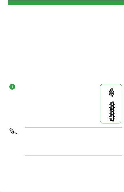
ATX power connectors (24-pin EATXPWR, 8-pin EATX12V)
Correctly orient the ATX power supply plugs into these connectors and push down firmly until the connectors completely fit.
EATX12V
|
GND |
+12V DC |
|
|
GND |
+12V DC |
|
|
GND |
+12V DC |
|
|
GND |
+12V DC |
|
|
PIN 1 |
||
|
EATXPWR |
||
|
+3 Volts |
GND |
|
|
+12 |
Volts |
+5 Volts |
|
+12 |
Volts |
+5 Volts |
|
+5V Standby |
+5 Volts |
|
|
Power OK |
-5 Volts |
|
|
GND |
GND |
|
|
+5 Volts |
GND |
|
|
GND |
GND |
|
|
+5 Volts |
PSON# |
|
|
GND |
GND |
|
|
+3 |
Volts |
-12 Volts |
|
+3 |
Volts |
+3 Volts |
|
PIN 1 |
•For a fully configured system, we recommend that you use a power supply unit (PSU) that complies with ATX 12 V Specification 2.0 (or later version) and provides a minimum power of 350 W. This PSU type has 24-pin and 8-pin power plugs.
•We recommend that you use a PSU with higher power output when configuring a system with more power-consuming devices or when you intend to install additional devices. The system may become unstable or may not boot up if the power is inadequate.
|
1-2 |
Chapter 1: Product Introduction |
 Loading…
View the manual for the Asus TUF B360-PRO Gaming here, for free. This manual comes under the category motherboards and has been rated by 1 people with an average of a 8.7. This manual is available in the following languages: English. Do you have a question about the Asus TUF B360-PRO Gaming or do you need help? Ask your question here
Can’t find the answer to your question in the manual? You may find the answer to your question in the FAQs about the Asus TUF B360-PRO Gaming below.
What is the width of the Asus TUF B360-PRO Gaming?
The Asus TUF B360-PRO Gaming has a width of 305 mm.
What is the depth of the Asus TUF B360-PRO Gaming?
The Asus TUF B360-PRO Gaming has a depth of 244 mm.
How do I install the Asus TUF B360-PRO Gaming motherboard properly?
When installing the motherboard, ensure that you correctly align the mounting holes with the standoffs in the computer case. Make sure to connect all necessary power cables and peripherals securely to the appropriate ports on the motherboard.
How do I connect the front panel connectors to the motherboard?
To connect the front panel connectors, carefully refer to the motherboard’s user manual to locate the specific pin layout for your case. Match the corresponding connectors to the correct pins, ensuring a solid connection.
How can I update the BIOS of my Asus TUF B360-PRO Gaming motherboard?
To update the BIOS, download the latest firmware version from the official Asus website. Copy the BIOS file onto a USB flash drive, and then enter the BIOS settings by pressing the DEL key during startup. From there, use the EZ Flash utility to locate and update the BIOS file from the USB drive.
How do I enable XMP (eXtreme Memory Profile) for my RAM?
To enable XMP for your RAM, access the BIOS settings by pressing the DEL key during startup. Navigate to the memory settings section and locate the XMP option. Enable it to automatically configure your RAM to its advertised speed and timings.
How can I monitor the temperature and performance of my Asus TUF B360-PRO Gaming motherboard?
You can utilize various software applications, such as AI Suite 3 or HWMonitor, to monitor the temperature and performance of your motherboard. These applications provide real-time data regarding temperatures, fan speeds, voltages, and other system information.
Does the Asus TUF B360-PRO Gaming support Intel processors?
Yes, the Asus TUF B360-PRO Gaming is compatible with Intel processors. This allows users to have a wide range of processor options to choose from.
Can the Asus TUF B360-PRO Gaming support a maximum of 64 GB of memory?
Yes, the Asus TUF B360-PRO Gaming can support a maximum of 64 GB of memory. This is a generous amount of memory, providing users with ample space for multitasking and running demanding applications.
Does the Asus TUF B360-PRO Gaming support Intel Turbo Boost Technology 2.0?
No, the Asus TUF B360-PRO Gaming does not support Intel Turbo Boost Technology 2.0. This means that the motherboard does not have the ability to automatically increase the clock speed of the processor for improved performance. However, it still offers a strong and capable performance.
Can the Asus TUF B360-PRO Gaming support high-resolution displays?
Yes, the Asus TUF B360-PRO Gaming can support a maximum resolution of 4096 x 2160 pixels. This allows users to connect high-resolution displays, such as Ultra HD 4K monitors, for a crisp and detailed visual experience.
Does the Asus TUF B360-PRO Gaming have a dedicated graphics card?
No, the Asus TUF B360-PRO Gaming does not have a dedicated graphics card. Instead, it utilizes the integrated graphics card, specifically the HD Graphics from Intel. While this may not provide the same level of performance as a dedicated graphics card, it still offers decent graphics capabilities for everyday use and casual gaming.
Is the manual of the Asus TUF B360-PRO Gaming available in English?
Yes, the manual of the Asus TUF B360-PRO Gaming is available in English .
Is your question not listed? Ask your question here
E13810
First Edition
February 2018
Copyright © 2018 ASUSTeK COMPUTER INC. All Rights Reserved.
No part of this manual, including the products and software described in it, may be reproduced,
transmitted, transcribed, stored in a retrieval system, or translated into any language in any form or by any
means, except documentation kept by the purchaser for backup purposes, without the express written
permission of ASUSTeK COMPUTER INC. («ASUS»).
Product warranty or service will not be extended if: (1) the product is repaired, modified or altered, unless
such repair, modification of alteration is authorized in writing by ASUS; or (2) the serial number of the
product is defaced or missing.
ASUS PROVIDES THIS MANUAL «AS IS» WITHOUT WARRANTY OF ANY KIND, EITHER EXPRESS
OR IMPLIED, INCLUDING BUT NOT LIMITED TO THE IMPLIED WARRANTIES OR CONDITIONS OF
MERCHANTABILITY OR FITNESS FOR A PARTICULAR PURPOSE. IN NO EVENT SHALL ASUS, ITS
DIRECTORS, OFFICERS, EMPLOYEES OR AGENTS BE LIABLE FOR ANY INDIRECT, SPECIAL,
INCIDENTAL, OR CONSEQUENTIAL DAMAGES (INCLUDING DAMAGES FOR LOSS OF PROFITS,
LOSS OF BUSINESS, LOSS OF USE OR DATA, INTERRUPTION OF BUSINESS AND THE LIKE),
EVEN IF ASUS HAS BEEN ADVISED OF THE POSSIBILITY OF SUCH DAMAGES ARISING FROM ANY
DEFECT OR ERROR IN THIS MANUAL OR PRODUCT.
SPECIFICATIONS AND INFORMATION CONTAINED IN THIS MANUAL ARE FURNISHED FOR
INFORMATIONAL USE ONLY, AND ARE SUBJECT TO CHANGE AT ANY TIME WITHOUT NOTICE,
AND SHOULD NOT BE CONSTRUED AS A COMMITMENT BY ASUS. ASUS ASSUMES NO
RESPONSIBILITY OR LIABILITY FOR ANY ERRORS OR INACCURACIES THAT MAY APPEAR IN THIS
MANUAL, INCLUDING THE PRODUCTS AND SOFTWARE DESCRIBED IN IT.
Products and corporate names appearing in this manual may or may not be registered trademarks or
copyrights of their respective companies, and are used only for identification or explanation and to the
owners’ benefit, without intent to infringe.
Offer to Provide Source Code of Certain Software
This product contains copyrighted software that is licensed under the General Public License («GPL»),
under the Lesser General Public License Version («LGPL») and/or other Free Open Source Software
Licenses. Such software in this product is distributed without any warranty to the extent permitted by the
applicable law. Copies of these licenses are included in this product.
Where the applicable license entitles you to the source code of such software and/or other additional data,
you may obtain it for a period of three years after our last shipment of the product, either
(1) for free by downloading it from https://www.asus.com/support/
or
(2) for the cost of reproduction and shipment, which is dependent on the preferred carrier and the location
where you want to have it shipped to, by sending a request to:
ASUSTeK Computer Inc.
Legal Compliance Dept.
15 Li Te Rd.,
Beitou, Taipei 112
Taiwan
In your request please provide the name, model number and version, as stated in the About Box of the
product for which you wish to obtain the corresponding source code and your contact details so that we
can coordinate the terms and cost of shipment with you.
The source code will be distributed WITHOUT ANY WARRANTY and licensed under the same license as
the corresponding binary/object code.
This offer is valid to anyone in receipt of this information.
ASUSTeK is eager to duly provide complete source code as required under various Free Open Source
Software licenses. If however you encounter any problems in obtaining the full corresponding source
code we would be much obliged if you give us a notification to the email address gpl@asus.com, stating
the product and describing the problem (please DO NOT send large attachments such as source code
archives, etc. to this email address).
ii