Посмотреть инструкция для Asus Prime X570-P бесплатно. Руководство относится к категории материнские платы, 4 человек(а) дали ему среднюю оценку 9. Руководство доступно на следующих языках: английский. У вас есть вопрос о Asus Prime X570-P или вам нужна помощь? Задайте свой вопрос здесь
Материнская плата ASUS Prime X570-P предназначена для установки процессоров AMD с использованием сокета AM4. Она совместима с такими сериями процессоров, как AMD Ryzen 3 2-го поколения, AMD Ryzen 3 3-го поколения, AMD Ryzen 5 2-го поколения, AMD Ryzen 5 3-го поколения, AMD Ryzen 7 2-го поколения, AMD Ryzen 7 3-го поколения и AMD Ryzen 9 3-го поколения. Максимальное количество процессоров на SMP — 1. Поддерживаемые сокеты процессоров — Socket AM4. В материнской плате имеется 4 слота для памяти типа DIMM, с возможностью использования модулей памяти с частотой 2133, 2400, 2666, 2800, 2933, 3000, 3200, 3400, 3466, 3600, 3733, 3866, 4000, 4133, 4266 и 4400 МГц. ECC поддерживается. Максимальный объем внутренней памяти составляет 128 ГБ. Ненакопительная память также поддерживается.
Материнская плата поддерживает интерфейсы хранения данных, такие как M.2, PCI Express 4.0 и SATA III. Имеется поддержка RAID. Плата не содержит интегрированной графики.
В целом, материнская плата ASUS Prime X570-P является качественным и стабильным продуктом. Совместимость с широким диапазоном процессоров AMD гарантирует высокую производительность и расширенные возможности для пользователей. Это одна из самых продвинутых и надежных материнских плат на рынке, подходящих для различных задач, начиная от игровых ПК до компьютеров для профессионального использования. Конструкция материнской платы, а также использование премиальных материалов, обеспечивает долговечность и надежность работы продукта.

Главная
| Asus | |
| Prime X570-P | 90MB11N0-M0EAY0 | |
| материнская плата | |
| 0192876263815, 4718017263818 | |
| английский | |
| Руководство пользователя (PDF) |
Процессор
| Производитель процессора | AMD |
| Сокет процессора | Разъем AM4 |
| Совместимые серии процессоров | AMD Ryzen 3 2nd Gen, AMD Ryzen 3 3rd Gen, AMD Ryzen 5 2nd Gen, AMD Ryzen 5 3rd Gen, AMD Ryzen 7 2nd Gen, AMD Ryzen 7 3rd Gen, AMD Ryzen 9 3rd Gen |
| Максимальное число процессоров для SMP | 1 |
| Поддерживаемые сокеты процессоров | Разъем AM4 |
Память
| Поддерживаемые типы памяти | DDR4-SDRAM |
| Количество слотов памяти | 4 |
| Тип слотов памяти | DIMM |
| Каналы памяти | Dual-channel |
| Поддерживаемые частоты памяти | 2133,2400,2666,2800,2933,3000,3200,3400,3466,3600,3733,3866,4000,4133,4266,4400 MHz |
| Error-correcting code (ECC) | Да |
| Максимальная внутренняя память | 128 GB |
| Небуферизованная память | Да |
Контроллеры хранения данных
| Поддерживаемые интерфейсы носителя | M.2, PCI Express 4.0, SATA III |
| Поддержка RAID | Да |
| Уровни RAID | 0, 1 |
Графический адаптер
| Поддержка технологии параллельной обработки | 2-Way CrossFireX |
| Максимальное разрешение | 4096 x 2160 пикселей |
Внутренние порты
| Разъемы USB 2.0 | 2 |
| Разъемы USB 3.2 Gen 1 (3.1 Gen 1) | 2 |
| Разъемы USB 3.2 Gen 2 (3.1 Gen 2) | 0 |
| Количество разъемов SATA III | 6 |
| Разъем выхода S/PDIF | Да |
| Аудиоразъем передней панели | Да |
| Разъем передней панели | Да |
| Разъем питания ATX (24-конт.) | Да |
| Количество разъемов питания EATX | 1 |
| Разъем вентилятора центрального процессора | Да |
| Количество разъемов вентилятора корпуса | 3 |
| Количество COM-разъёмов | 1 |
| TPM коннектор | Да |
| 12В разъем питания | Да |
| RGB LED контактный разъем | Да |
Порты на задней панели
| Количество портов USB 2.0 | 2 |
| Количество портов USB 3.2 Gen 1 (3.1 Gen 1) Type-A | 2 |
| Количество портов USB 3.2 Gen 1 (3.1 Gen 1) Type-С | 0 |
| Количество портов USB 3.2 Gen 2 (3.1 Gen 2) Type-A | 4 |
| Количество портов USB 3.2 Gen 2 (3.1 Gen 2) Type-С | 0 |
| Количество портов Ethernet LAN ( RJ-45) | 1 |
| Количество портов VGA (D-Sub) | 0 |
| Количество HDMI портов | 1 |
| Количество портов DVI-D | 0 |
| Количество портов PS/2 | 1 |
| Версия HDMI | 1.4b |
| Линейные выходы наушников | 3 |
Сеть
| Подключение Ethernet | Да |
| Тип Ethernet интерфейса | Гигабитный Ethernet |
| Контроллер LAN | Realtek RTL8111H |
| Функция Wake-on-LAN | Да |
| Wi-Fi | Нет |
| Bluetooth | Нет |
Свойства
| Комплектующие для | ПК |
| Формат материнской платы | ATX |
| Семейство чипсета материнской платы | AMD |
| Чипсет материнской платы | AMD X570 |
| Выходные звуковые каналы | 8 канала |
| Аудио чип | Realtek ALC S1200A |
| Поддерживаемые операционные системы Windows | Windows 10 x64 |
Слоты расширения
| PCI Express x1 слоты | 3 |
| Слоты PCI Express x16 (поколение 3.x) | 1 |
| Слоты PCI Express x16 (Gen 4.x) | 1 |
| Количество M.2 (M) слотов | 2 |
BIOS
| Тип BIOS | UEFI AMI |
| Размер памяти BIOS | 256 Mbit |
| Версия ACPI | 6.2 |
| Перемычка Clear CMOS | Да |
| Версия BIOS (SMBIOS) | 3.2 |
Вес и размеры
| Ширина | 305 mm |
| Глубина | 244 mm |
| Высота | 53 mm |
Содержимое упаковки
| Поставляемые кабели | SATA |
| Драйвера в комплекте | Да |
Логистические данные
| Код гармонизированной системы описания (HS) | 84733020 |
Прочие свойства
показать больше
Не можете найти ответ на свой вопрос в руководстве? Вы можете найти ответ на свой вопрос ниже, в разделе часто задаваемых вопросов о Asus Prime X570-P.
Какой вес Asus Prime X570-P?
Asus Prime X570-P имеет вес 1000 g.
Какая высота Asus Prime X570-P?
Asus Prime X570-P имеет высоту 53 mm.
Какая ширина Asus Prime X570-P?
Asus Prime X570-P имеет ширину 305 mm.
Какая толщина Asus Prime X570-P?
Asus Prime X570-P имеет толщину 244 mm.
Инструкция Asus Prime X570-P доступно в русский?
К сожалению, у нас нет руководства для Asus Prime X570-P, доступного в русский. Это руководство доступно в английский.
Не нашли свой вопрос? Задайте свой вопрос здесь
Посмотреть инструкция для Asus Prime X570-P бесплатно. Руководство относится к категории материнские платы, 4 человек(а) дали ему среднюю оценку 9. Руководство доступно на следующих языках: английский. У вас есть вопрос о Asus Prime X570-P или вам нужна помощь? Задайте свой вопрос здесь
Не можете найти ответ на свой вопрос в руководстве? Вы можете найти ответ на свой вопрос ниже, в разделе часто задаваемых вопросов о Asus Prime X570-P.
Какой вес Asus Prime X570-P?
Какая высота Asus Prime X570-P?
Какая ширина Asus Prime X570-P?
Какая толщина Asus Prime X570-P?
Инструкция Asus Prime X570-P доступно в русский?
Не нашли свой вопрос? Задайте свой вопрос здесь
Ваш электронный адрес не будет опубликован. Обязательные поля помечены * *
КОММЕНТАРИЙ *
Имя и фамилия
Эл. адрес
Cайт
Сохраните мое имя, адрес электронной почты и веб-сайт в этом браузере для следующего комментария.
![]()

E15650
Revised Edition V2 2019
Copyright © 2019 ASUSTeK COMPUTER INC. All Rights Reserved.
No part of this manual, including the products and software described in it, may be reproduced, transmitted, transcribed, stored in a retrieval system, or translated into any language in any form or by any means, except documentation kept by the purchaser for backup purposes, without the express written permission of ASUSTeK COMPUTER INC. (“ASUS”).
Product warranty or service will not be extended if: (1) the product is repaired, modified or altered, unless such repair, modification of alteration is authorized in writing by ASUS; or (2) the serial number of the product is defaced or missing.
ASUS PROVIDES THIS MANUAL “AS IS” WITHOUT WARRANTY OF ANY KIND, EITHER EXPRESS OR IMPLIED, INCLUDING BUT NOT LIMITED TO THE IMPLIED WARRANTIES OR CONDITIONS OF MERCHANTABILITY OR FITNESS FOR A PARTICULAR PURPOSE. IN NO EVENT SHALL ASUS, ITS DIRECTORS, OFFICERS, EMPLOYEES OR AGENTS BE LIABLE FOR ANY INDIRECT, SPECIAL, INCIDENTAL, OR CONSEQUENTIAL DAMAGES (INCLUDING DAMAGES FOR LOSS OF PROFITS, LOSS OF BUSINESS, LOSS OF USE OR DATA, INTERRUPTION OF BUSINESS AND THE LIKE), EVEN IF ASUS HAS BEEN ADVISED OF THE POSSIBILITY OF SUCH DAMAGES ARISING FROM ANY DEFECT OR ERROR IN THIS MANUAL OR PRODUCT.
SPECIFICATIONS AND INFORMATION CONTAINED IN THIS MANUAL ARE FURNISHED FOR INFORMATIONAL USE ONLY, AND ARE SUBJECT TO CHANGE AT ANY TIME WITHOUT NOTICE, AND SHOULD NOT BE CONSTRUED AS A COMMITMENT BY ASUS. ASUS ASSUMES NO RESPONSIBILITY OR LIABILITY FOR ANY ERRORS OR INACCURACIES THAT MAY APPEAR IN THIS MANUAL, INCLUDING THE PRODUCTS AND SOFTWARE DESCRIBED IN IT.
Products and corporate names appearing in this manual may or may not be registered trademarks or copyrights of their respective companies, and are used only for identification or explanation and to the owners’ benefit, without intent to infringe.
Offer to Provide Source Code of Certain Software
This product contains copyrighted software that is licensed under the General Public License (“GPL”), under the Lesser General Public License Version (“LGPL”) and/or other Free Open Source Software Licenses. Such software in this product is distributed without any warranty to the extent permitted by the applicable law. Copies of these licenses are included in this product.
Where the applicable license entitles you to the source code of such software and/or other additional data, you may obtain it for a period of three years after our last shipment of the product, either
(1)for free by downloading it from https://www.asus.com/support/
or
(2)for the cost of reproduction and shipment, which is dependent on the preferred carrier and the location where you want to have it shipped to, by sending a request to:
ASUSTeK Computer Inc.
Legal Compliance Dept.
15 Li Te Rd.,
Beitou, Taipei 112
Taiwan
In your request please provide the name, model number and version, as stated in the About Box of the product for which you wish to obtain the corresponding source code and your contact details so that we can coordinate the terms and cost of shipment with you.
The source code will be distributed WITHOUT ANY WARRANTY and licensed under the same license as the corresponding binary/object code.
This offer is valid to anyone in receipt of this information.
ASUSTeK is eager to duly provide complete source code as required under various Free Open Source Software licenses. If however you encounter any problems in obtaining the full corresponding source code we would be much obliged if you give us a notification to the email address gpl@asus.com, stating the product and describing the problem (please DO NOT send large attachments such as source code archives, etc. to this email address).
ii

Contents
|
Safety information…………………………………………………………………………………………. |
v |
|
About this guide……………………………………………………………………………………………. |
vi |
|
PRIME X570-P specifications summary……………………………………………………….. |
viii |
|
Package contents………………………………………………………………………………………… |
xii |
|
Installation tools and components……………………………………………………………….. |
xiii |
|
Chapter 1: |
Product Introduction |
||
|
1.1 |
Motherboard overview……………………………………………………………………. |
1-1 |
|
|
1.1.1 |
Before you proceed…………………………………………………………… |
1-1 |
|
|
1.1.2 |
Motherboard layout……………………………………………………………. |
1-2 |
|
|
1.1.3 |
Central Processing Unit (CPU)……………………………………………. |
1-4 |
|
|
1.1.4 |
System memory………………………………………………………………… |
1-4 |
|
|
1.1.5 |
Expansion slots…………………………………………………………………. |
1-6 |
|
|
1.1.6 |
Headers…………………………………………………………………………… |
1-8 |
|
|
1.1.7 |
Internal connectors………………………………………………………….. |
1-11 |
|
Chapter 2: |
Basic Installation |
||
|
2.1 |
Building your PC system………………………………………………………………… |
2-1 |
|
|
2.1.1 |
Motherboard installation…………………………………………………….. |
2-1 |
|
|
2.1.2 |
CPU installation………………………………………………………………… |
2-3 |
|
|
2.1.3 |
Cooling system installation…………………………………………………. |
2-4 |
|
|
2.1.4 |
DIMM installation………………………………………………………………. |
2-7 |
|
|
2.1.5 |
ATX power connection……………………………………………………….. |
2-8 |
|
|
2.1.6 |
SATA device connection…………………………………………………….. |
2-9 |
|
|
2.1.7 |
Front I/O connector………………………………………………………….. |
2-10 |
|
|
2.1.8 |
Expansion card installation……………………………………………….. |
2-11 |
|
|
2.1.9 |
M.2 installation………………………………………………………………… |
2-12 |
|
|
2.2 |
Motherboard rear and audio connections………………………………………. |
2-13 |
|
|
2.2.1 |
Rear I/O connection…………………………………………………………. |
2-13 |
|
|
2.2.2 |
Audio I/O connections………………………………………………………. |
2-15 |
|
|
2.3 |
Starting up for the first time………………………………………………………….. |
2-17 |
|
|
2.4 |
Turning off the computer………………………………………………………………. |
2-17 |
|
Chapter 3: |
BIOS Setup |
||
|
3.1 |
Knowing BIOS………………………………………………………………………………… |
3-1 |
|
|
3.2 |
BIOS setup program……………………………………………………………………….. |
3-2 |
|
|
3.2.1 |
EZ Mode………………………………………………………………………….. |
3-3 |
|
|
3.2.2 |
Advanced Mode………………………………………………………………… |
3-4 |
|
|
3.2.3 |
Q-Fan Control…………………………………………………………………… |
3-7 |
iii

|
3.3 |
My Favorites…………………………………………………………………………………… |
3-9 |
|
|
3.4 |
Main menu……………………………………………………………………………………. |
3-11 |
|
|
3.5 |
Ai Tweaker menu………………………………………………………………………….. |
3-11 |
|
|
3.6 |
Advanced menu……………………………………………………………………………. |
3-12 |
|
|
3.6.1 |
AMD fTPM Configuration………………………………………………….. |
3-12 |
|
|
3.6.2 |
CPU Configuration…………………………………………………………… |
3-12 |
|
|
3.6.3 |
NB Configuration…………………………………………………………….. |
3-13 |
|
|
3.6.4 |
SATA Configuration…………………………………………………………. |
3-13 |
|
|
3.6.5 |
Onboard Devices Configuration…………………………………………. |
3-14 |
|
|
3.6.6 |
APM Configuration…………………………………………………………… |
3-14 |
|
|
3.6.7 |
PCI Subsytem Settings…………………………………………………….. |
3-15 |
|
|
3.6.8 |
USB Configuration…………………………………………………………… |
3-15 |
|
|
3.6.9 |
HDD/SSD SMART Information………………………………………….. |
3-16 |
|
|
3.6.10 |
Network Stack Configuration…………………………………………….. |
3-16 |
|
|
3.7 |
Monitor menu……………………………………………………………………………….. |
3-16 |
|
|
3.7.1 |
Q-Fan Configuration………………………………………………………… |
3-16 |
|
|
3.8 |
Boot menu……………………………………………………………………………………. |
3-16 |
|
|
3.8.1 |
Boot Configuration…………………………………………………………… |
3-16 |
|
|
3.8.2 |
CSM (Compatibility Support Module)…………………………………. |
3-17 |
|
|
3.8.3 |
Secure Boot……………………………………………………………………. |
3-17 |
|
|
3.9 |
Tool menu…………………………………………………………………………………….. |
3-17 |
|
|
3.9.1 |
ASUS EZ Flash 3 Utility……………………………………………………. |
3-17 |
|
|
3.9.2 |
ASUS User Profile…………………………………………………………… |
3-17 |
|
|
3.9.3 |
ASUS SPD Information…………………………………………………….. |
3-18 |
|
|
3.9.4 |
ASUS Armoury Crate……………………………………………………….. |
3-18 |
|
|
3.10 |
Exit menu……………………………………………………………………………………… |
3-18 |
|
|
3.11 |
Updating BIOS……………………………………………………………………………… |
3-19 |
|
|
3.11.1 |
EZ Update………………………………………………………………………. |
3-19 |
|
|
3.11.2 |
ASUS EZ Flash 3…………………………………………………………….. |
3-20 |
|
|
3.11.3 |
ASUS CrashFree BIOS 3…………………………………………………. |
3-22 |
Appendix
|
Notices ……………………………………………………………………………………………………… |
A-1 |
|
ASUS contact information………………………………………………………………………….. |
A-5 |
iv

Safety information
Electrical safety
•To prevent electrical shock hazards, disconnect the power cable from the electrical outlet before relocating the system.
•When adding or removing devices to or from the system, ensure that the power cables for the devices are unplugged before the signal cables are connected. If possible, disconnect all power cables from the existing system before you add a device.
•Before connecting or removing signal cables from the motherboard, ensure that all power cables are unplugged.
•Seek professional assistance before using an adapter or extension cord. These devices could interrupt the grounding circuit.
•Ensure that your power supply is set to the correct voltage in your area. If you are not sure about the voltage of the electrical outlet you are using, contact your local power company.
•If the power supply is broken, do not try to fix it by yourself. Contact a qualified service technician or your retailer.
Operation safety
•Before installing the motherboard and adding devices on it, carefully read all the manuals that came with the package.
•Before using the product, ensure all cables are correctly connected and the power cables are not damaged. If you detect any damage, contact your dealer immediately.
•To avoid short circuits, keep paper clips, screws, and staples away from connectors, slots, sockets and circuitry.
•Avoid dust, humidity, and temperature extremes. Do not place the product in any area where it may become wet.
•Place the product on a stable surface.
•If you encounter technical problems with the product, contact a qualified service technician or your retailer.
v

About this guide
This user guide contains the information you need when installing and configuring the motherboard.
How this guide is organized
This guide contains the following parts:
•Chapter 1: Product Introduction
This chapter describes the features of the motherboard and the new technology it supports. It includes description of the switches, jumpers, and connectors on the motherboard.
•Chapter 2: Basic Installation
This chapter lists the hardware setup procedures that you have to perform when installing system components.
•Chapter 3: BIOS Setup
This chapter tells how to change system settings through the BIOS Setup menus. Detailed descriptions of the BIOS parameters are also provided.
•Chapter 4: RAID Support
This chapter describes the RAID configurations.
Where to find more information
Refer to the following sources for additional information and for product and software updates.
1.ASUS website
The ASUS website (www.asus.com) provides updated information on ASUS hardware and software products.
2.Optional documentation
Your product package may include optional documentation, such as warranty flyers, that may have been added by your dealer. These documents are not part of the standard package.
vi
Conventions used in this guide
To ensure that you perform certain tasks properly, take note of the following symbols used throughout this manual.
DANGER/WARNING: Information to prevent injury to yourself when trying to complete a task.
CAUTION: Information to prevent damage to the components when trying to complete a task.
IMPORTANT: Instructions that you MUST follow to complete a task.
NOTE: Tips and additional information to help you complete a task.
Typography
|
Bold text |
Indicates a menu or an item to select. |
|
Italics |
Used to emphasize a word or a phrase. |
|
<Key> |
Keys enclosed in the less-than and greater-than sign |
|
means that you must press the enclosed key. |
|
|
Example: <Enter> means that you must press the Enter or |
|
|
Return key. |
|
|
<Key1> + <Key2> + <Key3> |
If you must press two or more keys simultaneously, the key |
|
names are linked with a plus sign (+). |
vii

PRIME X570-P specifications summary
|
AMD AM4 Socket for 3rd and 2nd Gen AMD Ryzen™/2nd and 1st Gen |
||
|
AMD Ryzen™ with Radeon™ Vega Graphics Processors |
||
|
CPU |
Supports CPU up to 16 cores* |
|
|
* Due to the CPU limitations, CPU cores supported vary by processor. |
||
|
** Refer to www.asus.com for the AMD CPU support list. |
||
|
Chipset |
AMD X570 Chipset |
|
|
3rd Gen AMD Ryzen™ Processors |
||
|
— 4 x DIMM, max. 128GB, DDR4 4400(O.C.)/4266(O.C.)/4133(O.C. |
||
|
)/4000(O.C.)/3866(O.C.)/3733(O.C.)/3600(O.C.)/3466(O.C.)/3400 |
||
|
(O.C.)/3200/3000/2933/2800/2666/2400/2133 MHz, un-buffered |
||
|
memory |
||
|
2nd Gen AMD Ryzen™ Processors |
||
|
— 4 x DIMM, max. 128GB, DDR4 3600(O.C.)/3466(O.C.)/3400(O.C |
||
|
.)/3200(O.C.)/3000(O.C.)/2933/2800/2666/2400/2133 MHz, un- |
||
|
Memory |
buffered memory |
|
|
2nd and 1st Gen AMD Ryzen™ with Radeon™ Vega Graphics |
||
|
Processors |
||
|
— 4 x DIMM, max. 128GB, DDR4 3200(O.C.)/3000(O |
||
|
.C.)/2933/2800/2666/2400/2133 MHz, un-buffered memory |
||
|
Dual channel memory architecture |
||
|
ECC Memory (ECC mode) support varies by CPU. |
||
|
* The maximum memory capacity supported vary depending on the CPU |
||
|
you installed. |
||
|
** Refer to www.asus.com for the Memory QVL (Qualified Vendors List). |
||
|
3rd Gen AMD Ryzen™ Processors |
||
|
— 1 x PCIe 4.0 x16 slot (at x16 mode) |
||
|
2nd Gen AMD Ryzen™ Processors |
||
|
— 1 x PCIe 3.0 x16 slot (at x16 mode) |
||
|
Expansion slots |
2nd and 1st Gen AMD Ryzen™ with Radeon™ Vega Graphics |
|
|
Processors |
||
|
— 1 x PCIe 3.0 x16 slot (at x8 mode) |
||
|
AMD X570 chipset |
||
|
— 1 x PCIe 4.0 x16 slot (max. at x4 mode) |
||
|
— 3 x PCIe 4.0 x1 slots |
||
|
Integrated Graphics in the 2nd and 1st Gen AMD Ryzen™ with |
||
|
Graphics |
Radeon™ Vega Graphics Processors |
|
|
VGA output support: HDMI port |
||
|
— Supports HDMI 1.4b with max. resolution 4096 x 2160 @ 24 Hz |
||
|
3rd and 2nd Gen AMD Ryzen™/2nd and 1st Gen AMD Ryzen™ with |
||
|
Multi-GPU support |
Radeon™ Vega Graphics Processors |
|
|
— Supports AMD 2-way CrossFireX™ Technology |
||
|
(continued on the next page) |
viii

PRIME X570-P specifications summary
|
3rd Gen AMD Ryzen™ Processors |
||
|
— M.2_1 socket 3 with M Key, Type 2242/2260/2280 (PCIE 4.0 x4 and |
||
|
SATA modes) storage devices support |
||
|
2nd Gen AMD Ryzen™/2nd and 1st Gen AMD Ryzen™ with |
||
|
Radeon™ Vega Graphics Processors |
||
|
Storage |
— M.2_1 socket 3 with M Key, Type 2242/2260/2280 (PCIE 3.0 x4 and |
|
|
SATA modes) storage devices support |
||
|
AMD X570 Chipset |
||
|
— M.2_2 socket 3 with M Key, Type 2242/2260/2280/22110 (PCIE 4.0 |
||
|
x4 and SATA modes) storage devices support |
||
|
— 6 x Serial ATA 6.0 Gb/s connectors with RAID 0, RAID 1 and RAID |
||
|
10 support |
||
|
LAN |
Realtek® 8111H Gigabit LAN |
|
|
Realtek® S1200A 8-channel* high definition audio CODEC |
||
|
— Audio shielding: ensures precise analog/digital separation and |
||
|
greatly reduced multi-lateral interference |
||
|
— Dedicated audio PCB layers: Separate layers for left and right |
||
|
Audio |
channels to guard the quality of the sensitive audio signals |
|
|
— Premium Japan-made audio capacitors: provides warm, natural, and |
||
|
immersive sound with exceptional clarity and fidelity |
||
|
— Supports jack-detection and front panel jack-retasking |
||
|
* Choose the chassis with HD audio module in front panel to support |
||
|
8-channel audio output. |
||
|
3rd and 2nd Gen AMD Ryzen™/2nd and 1st Gen AMD Ryzen™ with |
||
|
Radeon™ Vega Graphics Processors |
||
|
— 2 x USB 3.2 Gen 1 (up to 5Gbps) ports (2 ports at back panel) |
||
|
— 2 x USB 3.2 Gen 2 (up to 10Gbps) ports (2 ports at back panel)* |
||
|
USB |
* The USB ports under the LAN port can run at USB 3.2 Gen 2 speeds with |
|
|
3rd Gen AMD Ryzen™ Processors. |
||
|
AMD X570 chipset |
||
|
— 2 x USB 3.2 Gen 2 (up to 10Gbps) ports (2 ports at back panel) |
||
|
— 4 x USB 3.2 Gen 1 (up to 5Gbps) ports (4 ports at mid-board) |
||
|
— 5 x USB 2.0 ports (2 ports at back panel, 3 ports at mid-board) |
||
|
ASUS 5X Protection III |
||
|
— ASUS SafeSlot Core — Fortified PCIe with solid soldering |
||
|
ASUS Unique |
— ASUS LANGuard — Protects against LAN surges, lightning strikes |
|
|
and static-electricity discharges! |
||
|
Features |
||
|
— ASUS Overvoltage Protection — World-class circuit-protecting |
||
|
power design |
||
|
— ASUS DIGI+ VRM — Digital power design with Dr. MOS |
||
(continued on the next page)
ix

PRIME X570-P specifications summary
|
— ASUS DRAM Overcurrent Protection: Enhanced DRAM |
|
|
overcurrent protection |
|
|
— ASUS Stainless-Steel Back I/O: 3X corrosion-resistance for |
|
|
greater durability! |
|
|
— ASUS ESD Guards — Enhanced ESD protection |
|
|
ASUS SafeSlot |
|
|
— Protect your graphics card Investment |
|
|
Armoury Crate |
|
|
Visual Beauty |
|
|
— Aura Control |
|
|
— Aura RGB Strip Headers |
|
|
— Addressable Gen 2 Header |
|
|
ASUS Exclusive Features |
|
|
— OptiMem |
|
|
— ASUS AI Charger |
|
|
ASUS Unique Features |
— ASUS AI Suite 3 |
|
— EPU |
|
Superb performance |
||
|
UEFI BIOS |
||
|
— Most advanced options with fast response time |
||
|
Easy PC DIY |
||
|
Safe motherboard mounting |
||
|
— Component-free areas to minimize damage risk |
||
|
UEFI BIOS EZ Mode |
||
|
— featuring friendly graphics user interface |
||
|
— ASUS CrashFree BIOS 3 |
||
|
— ASUS EZ Flash 3 |
||
|
ASUS Q-Design |
||
|
— ASUS Q-Slot |
||
|
— ASUS Q-DIMM |
||
|
ASUS Quiet Thermal |
— ASUS Fan Xpert 4 |
|
|
— Stylish Design: MOS Heat-sink with dual thermal pads design, |
||
|
Solution |
||
|
PCH Fan and PCH Heatsink |
||
1 x PS/2 keyboard/mouse combo port
1 x HDMI port
1 x LAN (RJ-45) port
4 x USB 3.2 Gen 2 (up to 10Gbps) ports (Type-A)* Back I/O Ports 2 x USB 3.2 Gen 1 (up to 5Gbps) ports (Type-A)
2 x USB 2.0/1.1 ports
3 x Audio jacks support 8-channel audio output
*The USB ports under the LAN port can run at USB 3.2 Gen 2 speeds with 3rd Gen AMD Ryzen™ Processors .
(continued on the next page)
x
![]()
PRIME X570-P specifications summary
|
2 x USB 3.2 Gen 1 (up to 5Gbps) connectors support additional 4 |
||
|
USB 3.2 Gen 1 ports |
||
|
2 x USB 2.0/1.1 connectors support additional 3 USB 2.0/1.1 ports |
||
|
1 x M.2_1 Socket 3 for M Key, type 2242/2260/2280 devices |
||
|
support (both SATA & PCIE mode) |
||
|
1 x M.2_2 Socket 3 for M Key, type 2242/2260/2280/22110 |
||
|
devices support (both SATA & PCIE mode) |
||
|
6 x SATA 6.0Gb/s connectors (gray) |
||
|
1 x CPU Fan header (4-pin) for both 3-pin(DC mode) and |
||
|
4-pin(PWM mode) CPU coolers control with auto detection |
||
|
support |
||
|
1 x AIO Pump header (4-pin) |
||
|
3 x Chassis Fan connectors (4-pin) for both 3-pin(DC mode) and |
||
|
Internal I/O Ports |
4-pin(PWM mode) coolers control with auto detection support |
|
|
1 x PCH _FAN connector (4-pin) |
||
|
2 x Aura RGB headers |
||
|
1 x Addressable Gen 2 header |
||
|
1 x COM header |
||
|
1 x SPI_TPM header |
||
|
1 x S/PDIF out header |
||
|
1 x System Panel connector |
||
|
1 x Front panel audio connector (AAFP) |
||
|
1 x 24-pin EATX Power connector |
||
|
1 x 8-pin EATX 12V Power connector |
||
|
1 x 4-pin EATX 12V Power connector |
||
|
1 x Clear CMOS jumper |
||
|
256 Mb Flash ROM, UEFI AMI BIOS, PnP, SM BIOS 3.2, ACPI |
||
|
BIOS |
6.2, Multi-language BIOS, ASUS EZ Flash 3, CrashFree BIOS |
|
|
3, F6 Qfan Control, F3 My Favorites, Last Modified log, F12 |
||
|
PrintScreen, F4 AURA ON/OFF, F9 Search and ASUS DRAM SPD |
||
|
(Serial Presence Detect) memory information |
|
Manageability |
WOL by PME, PXE |
|
|
Drivers |
||
|
Support DVD contents |
ASUS Utilities |
|
|
EZ Update |
||
|
Operating System Support |
Windows® 10 64-bit |
|
|
Form Factor |
ATX Form Factor, 12”x 9.6” (30.5cm x 24.4cm) |
|
|
• |
Specifications are subject to change without notice. |
|
|
• |
visit the ASUS website for the software manual |
xi

PRIME X570-P specifications summary
Package contents
Check your motherboard package for the following items.
|
Motherboard |
1 x PRIME X570-P |
|
|
Cables |
2 x SATA 6 Gb/s cables |
|
|
1 x Addressable RGB header extension cable |
||
|
Accessories |
1 x IO Shield |
|
|
1 x M.2 screw package |
||
|
Application DVD |
Motherboard support DVD |
|
|
Documentation |
User guide |
If any of the above items are damaged or missing, contact your retailer.
xii
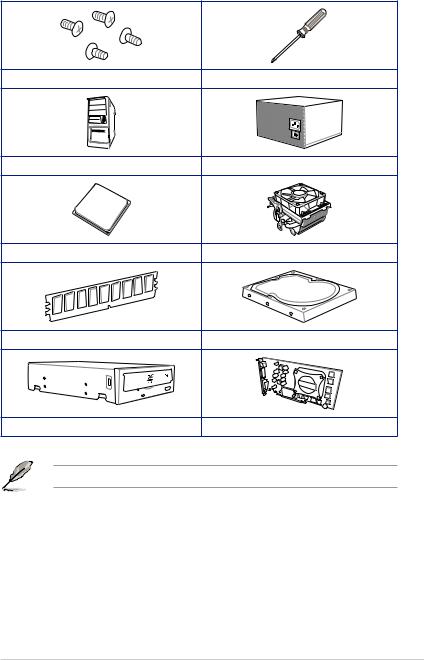
Installation tools and components
|
1 Bag of screws |
Phillips (cross) screwdriver |
|
PC chassis |
Power supply unit |
|
AMD AM4 CPU |
AMD AM4/AM3 compatible CPU Fan |
|
DDR4 DIMM |
SATA hard disk drive |
|
SATA optical disc drive (optional) |
Graphics card (optional) |
The tools and components in the table above are not included in the motherboard package.
xiii

xiv

1.1Motherboard overview
1.1.1Before you proceed
Take note of the following precautions before you install motherboard components or change any motherboard settings.
•Unplug the power cord from the wall socket before touching any component.
•Before handling components, use a grounded wrist strap or touch a safely grounded object or a metal object, such as the power supply case, to avoid damaging them due to static electricity.
•Hold components by the edges to avoid touching the ICs on them.
•Whenever you uninstall any component, place it on a grounded antistatic pad or in the bag that came with the component.
•Before you install or remove any component, ensure that the ATX power supply is switched off or the power cord is detached from the power supply. Failure to do so may cause severe damage to the motherboard, peripherals, or components.
Chapter 1

1 Chapter
1.1.2Motherboard layout
|
1 |
2 |
3 |
4 |
2 |
5 |
6 |
24.4cm(9.6in)
|
CPU_FAN |
|||||||||||||
|
RGB_HEADER1 |
|||||||||||||
|
KBMS |
CHA_FAN2 |
||||||||||||
|
EATX12V_2 |
EATX12V_1 |
||||||||||||
|
_USB78 |
|||||||||||||
|
DIGI |
|||||||||||||
|
+VRM |
|||||||||||||
|
U32G1_56 |
|||||||||||||
|
AUDIO |
LANGuard |
PUMP |
SOCKETAM4 |
DIMMDDR4B1 (64bit, 288-pin module) |
DIMMDDR4B2* (64bit, 288-pin module) |
DIMMDDR4A1 (64bit, 288-pin module) |
DIMMDDR4A2* (64bit, 288-pin module) |
34U32G1 |
2 |
30.5cm(12in) |
8 |
||
|
BIOS |
ADD GEN |
||||||||||||
|
7 |
|||||||||||||
|
U32G2_12 |
|||||||||||||
|
HDMI |
EATXPWR |
||||||||||||
|
1 |
|||||||||||||
|
LAN_U32G2_34 |
|||||||||||||
|
SPI_TPM |
|||||||||||||
|
256Mb |
|||||||||||||
|
AIO |
|||||||||||||
|
PCIEX1_1 |
|
PCIEX16_1 |
|||||||||||
|
Realtek® |
_FAN |
1 |
9 |
||||||||
|
8111H |
BATTERY |
||||||||||
|
PCH |
SATA6G |
||||||||||
|
10 |
|||||||||||
|
1(SOCKET3) |
X570 |
SATA6G2 |
|||||||||
|
AMD® |
|||||||||||
|
Super |
2280 |
2260 |
2242 |
_ |
|||||||
|
I/O |
M.2 |
||||||||||
|
PCIEX16_2 |
11 |
||||||||||
|
Realtek® |
22110 |
2280 |
2260 |
2242 |
2(SOCKET3) |
10 |
|||||
|
S1200A |
PCIEX1_2 |
AURA |
|||||||||
|
M.2 |
SATA6G_3 SATA6G_4 |
||||||||||
|
PCIEX1_3 |
CLRTC |
||||||||||
|
SPDIF_OUT |
COM_DEBUG |
CHA_FAN3 |
SATA6G_6 |
||||||||
|
COM |
CHA_FAN1 |
USB910 USB11 |
U32G1_12 |
PANEL |
SATA6G_5 |
|
17 |
16 |
15 |
2 |
14 |
8 |
5 |
13 |
12 |
10 |
Refer to 1.1.7 Internal connectors and 2.2.1 Rear I/O connection for more information about rear panel connectors and internal connectors.
|
1-2 |
Chapter 1: Product Introduction |

Layout contents
|
Connectors/Jumpers/Buttons and switches/Slots |
Page |
|
|
1. |
ATX power connectors (24-pin EATXPWR; 8-pin EATX12V; 4-pin EATX |
1-17 |
|
12V;) |
||
|
2. |
CPU and chassis fan connectors; AIO pump connector (4-pin CPU_FAN, |
1-16 |
|
4-pin CHA_FAN1-3; 4-pin AIO_PUMP) |
||
|
3. |
SPI_TPM connector (14-1 pin SPI_TPM) |
1-11 |
|
4. |
AM4 CPU socket |
1-4 |
|
5. |
AURA RGB headers (4-pin RGB_HEADER1-2) |
1-9 |
|
6. |
DDR4 DIMM slots |
1-4 |
|
7. |
Addressable Gen 2 header (4-1pin ADD_GEN 2) |
1-10 |
|
8. |
USB 3.2 Gen 1 (up to 5Gbps) connectors (20-1 pin U32G1_12, U32G1_34) |
1-13 |
|
9. |
PCH fan header (4-pin PCH_FAN) |
1-17 |
|
10. |
AMD Serial ATA 6 Gb/s connectors (7-pin SATA6G_1-6) |
1-12 |
|
11. |
M.2 Socket 3 |
1-19 |
|
12. |
Clear RTC RAM jumper (2-pin CLRTC) |
1-8 |
|
13. |
System panel connectors (20-5 pin PANEL) |
1-15 |
|
14. |
USB 2.0 connectors (10-1 pin USB910, USB11) |
1-14 |
|
15. |
Serial port connector (10-1 pin COM) |
1-18 |
|
16. |
Front panel audio connector (10-1 pin AAFP) |
1-11 |
|
17. |
Digital audio connector (4-1 pin SPDIF_OUT) |
1-18 |
Chapter 1

1.1.3Central Processing Unit (CPU)
The motherboard comes with an AM4 socket designed for 3rd and 2nd Gen AMD Ryzen™/2nd and 1st Gen AMD Ryzen™ with Radeon™ Vega Graphics Processors up to 16 cores.
1 Chapter
PRIME X570-P CPU socket AM4
The AM4 socket has a different pinout design. Ensure that you use a CPU designed for the
AM4 socket. The CPU fits in only one correct orientation. DO NOT force the CPU into the socket to prevent bending the connectors on the socket and damaging the CPU!
Ensure that all power cables are unplugged before installing the CPU.
1.1.4System memory
The motherboard comes with four Double Data Rate 4 (DDR4) Dual Inline Memory Modules (DIMM) slots.
A DDR4 module is notched differently from a DDR, DDR2, or DDR3 module. DO NOT install a DDR, DDR2, or DDR3 memory module to the DDR4 slot.
|
DIMM B1 |
DIMM B2* |
DIMM A1 |
DIMM A2* |
PRIME X570-P 288-pin DDR4 DIMM sockets
|
1-4 |
Chapter 1: Product Introduction |
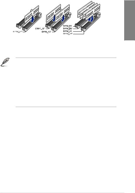
Recommended memory configurations
Chapter 1
Memory configurations
You may install 2 GB, 4 GB, 8 GB, 16 GB and 32 GB unbuffered DDR4 DIMMs into the DIMM sockets.
•The default memory operation frequency is dependent on its Serial Presence Detect
(SPD), which is the standard way of accessing information from a memory module. Under the default state, some memory modules for overclocking may operate at a lower frequency than the vendor-marked value.
•For system stability, use a more efficient memory cooling system to support a full memory load (4 DIMMs) or overclocking condition.
•Always install the DIMMS with the same CAS Latency. For an optimum compatibility, we recommend that you install memory modules of the same version or data code (D/C) from the same vendor. Check with the vendor to get the correct memory modules.
•Visit the ASUS website for the latest QVL.same vendor. Check with the vendor to get the correct memory modules.
1 Chapter
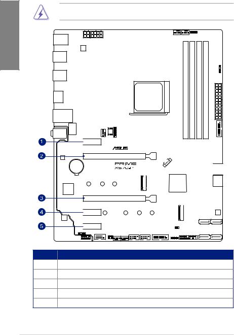
1.1.5Expansion slots
Unplug the power cord before adding or removing expansion cards. Failure to do so may cause you physical injury and damage motherboard components.
 PCIEX1_1
PCIEX16_1
PCIEX16_2
 PCIEX1_2
 PCIEX1_3
Slot No. Slot Description
1PCIe 4.0 x1_1 slot
2PCIe 4.0/3.0 x16_1 slot
3PCIe 4.0 x16_2 slot
4PCIe 4.0 x1_2 slot
5PCIe 4.0 x1_3 slot
|
1-6 |
Chapter 1: Product Introduction |
![]()
3rd Gen AMD Ryzen™ Processors
|
VGA Configuration |
PCIe operating mode |
||
|
PCIe 4.0 x16_1 |
PCIe 4.0 x16_2 |
||
|
Single VGA/PCIe card |
x16 |
N/A |
|
|
Dual VGA/PCIe card |
x16 |
x4 |
|
2nd Gen AMD Ryzen™ Processors
|
VGA Configuration |
PCIe operating mode |
||
|
PCIe 3.0 x16_1 |
PCIe 4.0 x16_2 |
||
|
Single VGA/PCIe card |
x16 |
N/A |
|
|
Dual VGA/PCIe card |
x16 |
x4 |
|
2nd and 1st Gen AMD Ryzen™ with Radeon™ Vega Graphics Processors
|
VGA Configuration |
PCIe operating mode |
||
|
PCIe 3.0 x16_1 |
PCIe 4.0 x16_2 |
||
|
Single VGA/PCIe card |
x8 |
N/A |
|
|
Dual VGA/PCIe card |
x8 |
x4 |
|
• In single VGA card mode, use the PCIe 4.0 / 3.0 X16_1 slot for a PCI Express x16 graphics card to get better performance.
•We recommend that you provide sufficient power when running CrossFireX ™ mode.
•Connect chassis fans to the motherboard chassis fan connectors when using multiple graphics cards for better thermal environment.
Chapter 1
1.1.6Headers
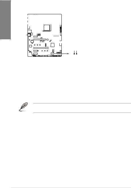
1. Clear RTC RAM jumper (2-pin CLRTC)
This jumper allows you to clear the CMOS RTC RAM data of the system setup
information such as date, time, and system passwords. Chapter1 


CLRTC
BAT_+3VGND
PIN 1
PRIME X570-P Clear RTC RAM
To erase the RTC RAM:
1.Turn OFF the computer and unplug the power cord.
2.Use a metal object such as a screwdriver to short the two pins.
3.Plug the power cord and turn ON the computer.
4.Hold down the <Del> key during the boot process and enter BIOS setup to re-enter data.
If the steps above do not help, remove the onboard battery and short the two pins again to clear the CMOS RTC RAM data. After clearing the CMOS, reinstall the battery.
|
1-8 |
Chapter 1: Product Introduction |
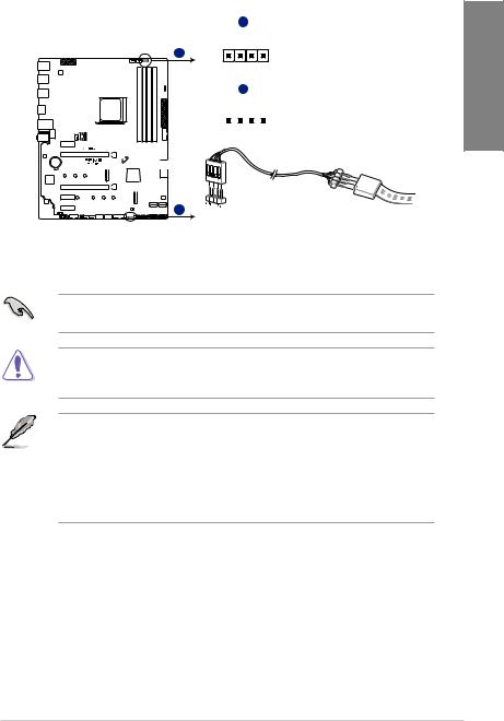
2.AURA RGB headers (4-pin RGB_HEADER1-2)
These connectors are for RGB LED strips.
A
RGB_HEADER1
A
PIN 1
+12V G R B
B
RGB_HEADER2
PIN 1 

+12V G R B
B
PRIME X570-P RGB_HEADER connectors
The RGB header supports 5050 RGB multi-color LED strips (12V/G/R/B), with a maximum power rating of 3A (12V), and no longer than 3 m.
Before you install or remove any component, ensure that the ATX power supply is switched off or the power cord is detached from the power supply. Failure to do so may cause severe
damage to the motherboard, peripherals, or components.
• Actual lighting and color will vary with LED strip.
• If your LED strip does not light up, check if the RGB LED extension cable and the RGB LED strip are connected in the correct orientation, and the 12V connector is aligned with the 12V header on the motherboard.
•The LED strip will only light up while the system is operational.
•The LED strip is purchased separately.
Chapter 1

1 Chapter
3.Addressable RGB Gen 2 header (4-1 pin ADD_GEN 2)
This connector is for individually addressable RGB WS2812B LED strips or WS2812B based LED strips.
 ADD_GEN 2
Ground 

Data 
+5V 
PIN 1
PRIME X570-P ADD_GEN 2 header
The addressable gen 2 RGB header supports WS2812B addressable RGB LED strips (5V/ Data/Ground), with a maximum power rating of 3A (5V) and a maximum of 120 LEDs
Before you install or remove any component, ensure that the ATX power supply is switched off or the power cord is detached from the power supply. Failure to do so may cause severe
damage to the motherboard, peripherals, or components
• Actual lighting and color will vary with LED strip.
• If your LED strip does not light up, check if the RGB LED extension cable and the RGB LED strip are connected in the correct orientation, and the 12V connector is aligned with the 12V header on the motherboard.
•The LED strip will only light up while the system is operational.
•The LED strip is purchased separately.
|
1-10 |
Chapter 1: Product Introduction |
 Loading…
-
Драйверы
13
-
Инструкции по эксплуатации
1

ASUS PRIME X570-P/CSM инструкция по эксплуатации
(196 страниц)
- Языки:Японский
-
Тип:
PDF -
Размер:
10.42 MB -
Описание:
ACC Express User’s Manual ( Japanese Edition )
Просмотр
На NoDevice можно скачать инструкцию по эксплуатации для ASUS PRIME X570-P/CSM. Руководство пользователя необходимо для ознакомления с правилами установки и эксплуатации ASUS PRIME X570-P/CSM. Инструкции по использованию помогут правильно настроить ASUS PRIME X570-P/CSM, исправить ошибки и выявить неполадки.
View a manual of the Asus Prime X570-P below. All manuals on ManualsCat.com can be viewed completely free of charge. By using the ‘Select a language’ button, you can choose the language of the manual you want to view.
Page: 1
Motherboard
PRIME X570-P
Page: 2
ii
E15650
Revised Edition V2
2019
Copyright © 2019 ASUSTeK COMPUTER INC. All Rights Reserved.
No part of this manual, including the products and software described in it, may be reproduced,
transmitted, transcribed, stored in a retrieval system, or translated into any language in any form or by any
means, except documentation kept by the purchaser for backup purposes, without the express written
permission of ASUSTeK COMPUTER INC. (“ASUS”).
Product warranty or service will not be extended if: (1) the product is repaired, modified or altered, unless
such repair, modification of alteration is authorized in writing by ASUS; or (2) the serial number of the
product is defaced or missing.
ASUS PROVIDES THIS MANUAL “AS IS” WITHOUT WARRANTY OF ANY KIND, EITHER EXPRESS
OR IMPLIED, INCLUDING BUT NOT LIMITED TO THE IMPLIED WARRANTIES OR CONDITIONS OF
MERCHANTABILITY OR FITNESS FOR A PARTICULAR PURPOSE. IN NO EVENT SHALL ASUS, ITS
DIRECTORS, OFFICERS, EMPLOYEES OR AGENTS BE LIABLE FOR ANY INDIRECT, SPECIAL,
INCIDENTAL, OR CONSEQUENTIAL DAMAGES (INCLUDING DAMAGES FOR LOSS OF PROFITS,
LOSS OF BUSINESS, LOSS OF USE OR DATA, INTERRUPTION OF BUSINESS AND THE LIKE),
EVEN IF ASUS HAS BEEN ADVISED OF THE POSSIBILITY OF SUCH DAMAGES ARISING FROM ANY
DEFECT OR ERROR IN THIS MANUAL OR PRODUCT.
SPECIFICATIONS AND INFORMATION CONTAINED IN THIS MANUAL ARE FURNISHED FOR
INFORMATIONAL USE ONLY, AND ARE SUBJECT TO CHANGE AT ANY TIME WITHOUT NOTICE,
AND SHOULD NOT BE CONSTRUED AS A COMMITMENT BY ASUS. ASUS ASSUMES NO
RESPONSIBILITY OR LIABILITY FOR ANY ERRORS OR INACCURACIES THAT MAY APPEAR IN THIS
MANUAL, INCLUDING THE PRODUCTS AND SOFTWARE DESCRIBED IN IT.
Products and corporate names appearing in this manual may or may not be registered trademarks or
copyrights of their respective companies, and are used only for identification or explanation and to the
owners’ benefit, without intent to infringe.
Offer to Provide Source Code of Certain Software
This product contains copyrighted software that is licensed under the General Public License (“GPL”),
under the Lesser General Public License Version (“LGPL”) and/or other Free Open Source Software
Licenses. Such software in this product is distributed without any warranty to the extent permitted by the
applicable law. Copies of these licenses are included in this product.
Where the applicable license entitles you to the source code of such software and/or other additional data,
you may obtain it for a period of three years after our last shipment of the product, either
(1) for free by downloading it from https://www.asus.com/support/
or
(2) for the cost of reproduction and shipment, which is dependent on the preferred carrier and the location
where you want to have it shipped to, by sending a request to:
ASUSTeK Computer Inc.
Legal Compliance Dept.
15 Li Te Rd.,
Beitou, Taipei 112
Taiwan
In your request please provide the name, model number and version, as stated in the About Box of the
product for which you wish to obtain the corresponding source code and your contact details so that we
can coordinate the terms and cost of shipment with you.
The source code will be distributed WITHOUT ANY WARRANTY and licensed under the same license as
the corresponding binary/object code.
This offer is valid to anyone in receipt of this information.
ASUSTeK is eager to duly provide complete source code as required under various Free Open Source
Software licenses. If however you encounter any problems in obtaining the full corresponding source
code we would be much obliged if you give us a notification to the email address gpl@asus.com, stating
the product and describing the problem (please DO NOT send large attachments such as source code
archives, etc. to this email address).
Page: 3
iii
Contents
Safety information………………………………………………………………………………………….. v
About this guide……………………………………………………………………………………………. vi
PRIME X570-P specifications summary………………………………………………………… viii
Package contents…………………………………………………………………………………………. xii
Installation tools and components……………………………………………………………….. xiii
Chapter 1: Product Introduction
1.1 Motherboard overview……………………………………………………………………..1-1
1.1.1 Before you proceed…………………………………………………………….1-1
1.1.2 Motherboard layout…………………………………………………………….1-2
1.1.3 Central Processing Unit (CPU)…………………………………………….1-4
1.1.4 System memory…………………………………………………………………1-4
1.1.5 Expansion slots………………………………………………………………….1-6
1.1.6 Headers……………………………………………………………………………1-8
1.1.7 Internal connectors…………………………………………………………..1-11
Chapter 2: Basic Installation
2.1 Building your PC system…………………………………………………………………2-1
2.1.1 Motherboard installation………………………………………………………2-1
2.1.2 CPU installation…………………………………………………………………2-3
2.1.3 Cooling system installation………………………………………………….2-4
2.1.4 DIMM installation……………………………………………………………….2-7
2.1.5 ATX power connection………………………………………………………..2-8
2.1.6 SATA device connection……………………………………………………..2-9
2.1.7 Front I/O connector…………………………………………………………..2-10
2.1.8 Expansion card installation………………………………………………..2-11
2.1.9 M.2 installation…………………………………………………………………2-12
2.2 Motherboard rear and audio connections……………………………………….2-13
2.2.1 Rear I/O connection………………………………………………………….2-13
2.2.2 Audio I/O connections……………………………………………………….2-15
2.3 Starting up for the first time……………………………………………………………2-17
2.4 Turning off the computer……………………………………………………………….2-17
Chapter 3: BIOS Setup
3.1 Knowing BIOS…………………………………………………………………………………3-1
3.2 BIOS setup program………………………………………………………………………..3-2
3.2.1 EZ Mode…………………………………………………………………………..3-3
3.2.2 Advanced Mode…………………………………………………………………3-4
3.2.3 Q-Fan Control……………………………………………………………………3-7
Page: 4
iv
3.3 My Favorites……………………………………………………………………………………3-9
3.4 Main menu…………………………………………………………………………………….3-11
3.5 Ai Tweaker menu…………………………………………………………………………..3-11
3.6 Advanced menu…………………………………………………………………………….3-12
3.6.1 AMD fTPM Configuration…………………………………………………..3-12
3.6.2 CPU Configuration……………………………………………………………3-12
3.6.3 NB Configuration………………………………………………………………3-13
3.6.4 SATA Configuration………………………………………………………….3-13
3.6.5 Onboard Devices Configuration………………………………………….3-14
3.6.6 APM Configuration……………………………………………………………3-14
3.6.7 PCI Subsytem Settings……………………………………………………..3-15
3.6.8 USB Configuration……………………………………………………………3-15
3.6.9 HDD/SSD SMART Information…………………………………………..3-16
3.6.10 Network Stack Configuration……………………………………………..3-16
3.7 Monitor menu………………………………………………………………………………..3-16
3.7.1 Q-Fan Configuration…………………………………………………………3-16
3.8 Boot menu…………………………………………………………………………………….3-16
3.8.1 Boot Configuration……………………………………………………………3-16
3.8.2 CSM (Compatibility Support Module)…………………………………..3-17
3.8.3 Secure Boot…………………………………………………………………….3-17
3.9 Tool menu……………………………………………………………………………………..3-17
3.9.1 ASUS EZ Flash 3 Utility…………………………………………………….3-17
3.9.2 ASUS User Profile……………………………………………………………3-17
3.9.3 ASUS SPD Information……………………………………………………..3-18
3.9.4 ASUS Armoury Crate………………………………………………………..3-18
3.10 Exit menu………………………………………………………………………………………3-18
3.11 Updating BIOS……………………………………………………………………………….3-19
3.11.1 EZ Update……………………………………………………………………….3-19
3.11.2 ASUS EZ Flash 3……………………………………………………………..3-20
3.11.3 ASUS CrashFree BIOS 3…………………………………………………..3-22
Appendix
Notices ……………………………………………………………………………………………………… A-1
ASUS contact information…………………………………………………………………………… A-5
Page: 5
v
Safety information
Electrical safety
• To prevent electrical shock hazards, disconnect the power cable from the electrical outlet
before relocating the system.
• When adding or removing devices to or from the system, ensure that the power cables
for the devices are unplugged before the signal cables are connected. If possible,
disconnect all power cables from the existing system before you add a device.
• Before connecting or removing signal cables from the motherboard, ensure that all
power cables are unplugged.
• Seek professional assistance before using an adapter or extension cord. These devices
could interrupt the grounding circuit.
• Ensure that your power supply is set to the correct voltage in your area. If you are not
sure about the voltage of the electrical outlet you are using, contact your local power
company.
• If the power supply is broken, do not try to fix it by yourself. Contact a qualified service
technician or your retailer.
Operation safety
• Before installing the motherboard and adding devices on it, carefully read all the manuals
that came with the package.
• Before using the product, ensure all cables are correctly connected and the power
cables are not damaged. If you detect any damage, contact your dealer immediately.
• To avoid short circuits, keep paper clips, screws, and staples away from connectors,
slots, sockets and circuitry.
• Avoid dust, humidity, and temperature extremes. Do not place the product in any area
where it may become wet.
• Place the product on a stable surface.
• If you encounter technical problems with the product, contact a qualified service
technician or your retailer.
Page: 6
vi
About this guide
This user guide contains the information you need when installing and configuring the
motherboard.
How this guide is organized
This guide contains the following parts:
• Chapter 1: Product Introduction
This chapter describes the features of the motherboard and the new technology it
supports. It includes description of the switches, jumpers, and connectors on the
motherboard.
• Chapter 2: Basic Installation
This chapter lists the hardware setup procedures that you have to perform when
installing system components.
• Chapter 3: BIOS Setup
This chapter tells how to change system settings through the BIOS Setup menus.
Detailed descriptions of the BIOS parameters are also provided.
• Chapter 4: RAID Support
This chapter describes the RAID configurations.
Where to find more information
Refer to the following sources for additional information and for product and software
updates.
1. ASUS website
The ASUS website (www.asus.com) provides updated information on ASUS hardware
and software products.
2. Optional documentation
Your product package may include optional documentation, such as warranty flyers,
that may have been added by your dealer. These documents are not part of the
standard package.
Page: 7
vii
Conventions used in this guide
To ensure that you perform certain tasks properly, take note of the following symbols used
throughout this manual.
DANGER/WARNING: Information to prevent injury to yourself when trying to
complete a task.
CAUTION: Information to prevent damage to the components when trying to
complete a task.
IMPORTANT: Instructions that you MUST follow to complete a task.
NOTE: Tips and additional information to help you complete a task.
Typography
Bold text Indicates a menu or an item to select.
Italics Used to emphasize a word or a phrase.
<Key> Keys enclosed in the less-than and greater-than sign
means that you must press the enclosed key.
Example: <Enter> means that you must press the Enter or
Return key.
<Key1> + <Key2> + <Key3> If you must press two or more keys simultaneously, the key
names are linked with a plus sign (+).
Page: 8
viii
PRIME X570-P specifications summary
(continued on the next page)
CPU
AMD AM4 Socket for 3rd
and 2nd
Gen AMD Ryzen™/2nd
and 1st
Gen
AMD Ryzen™ with Radeon™ Vega Graphics Processors
Supports CPU up to 16 cores*
* Due to the CPU limitations, CPU cores supported vary by processor.
** Refer to www.asus.com for the AMD CPU support list.
Chipset AMD X570 Chipset
Memory
3rd
Gen AMD Ryzen™ Processors
— 4 x DIMM, max. 128GB, DDR4 4400(O.C.)/4266(O.C.)/4133(O.C.
)/4000(O.C.)/3866(O.C.)/3733(O.C.)/3600(O.C.)/3466(O.C.)/3400
(O.C.)/3200/3000/2933/2800/2666/2400/2133 MHz, un-buffered
memory
2nd
Gen AMD Ryzen™ Processors
— 4 x DIMM, max. 128GB, DDR4 3600(O.C.)/3466(O.C.)/3400(O.C
.)/3200(O.C.)/3000(O.C.)/2933/2800/2666/2400/2133 MHz, un-
buffered memory
2nd
and 1st
Gen AMD Ryzen™ with Radeon™ Vega Graphics
Processors
— 4 x DIMM, max. 128GB, DDR4 3200(O.C.)/3000(O
.C.)/2933/2800/2666/2400/2133 MHz, un-buffered memory
Dual channel memory architecture
ECC Memory (ECC mode) support varies by CPU.
* The maximum memory capacity supported vary depending on the CPU
you installed.
** Refer to www.asus.com for the Memory QVL (Qualified Vendors List).
Expansion slots
3rd
Gen AMD Ryzen™ Processors
— 1 x PCIe 4.0 x16 slot (at x16 mode)
2nd
Gen AMD Ryzen™ Processors
— 1 x PCIe 3.0 x16 slot (at x16 mode)
2nd
and 1st
Gen AMD Ryzen™ with Radeon™ Vega Graphics
Processors
— 1 x PCIe 3.0 x16 slot (at x8 mode)
AMD X570 chipset
— 1 x PCIe 4.0 x16 slot (max. at x4 mode)
— 3 x PCIe 4.0 x1 slots
Graphics
Integrated Graphics in the 2nd
and 1st
Gen AMD Ryzen™ with
Radeon™ Vega Graphics Processors
VGA output support: HDMI port
— Supports HDMI 1.4b with max. resolution 4096 x 2160 @ 24 Hz
Multi-GPU support
3rd
and 2nd
Gen AMD Ryzen™/2nd
and 1st
Gen AMD Ryzen™ with
Radeon™ Vega Graphics Processors
— Supports AMD 2-way CrossFireX™ Technology
Page: 9
ix
(continued on the next page)
Storage
3rd
Gen AMD Ryzen™ Processors
— M.2_1 socket 3 with M Key, Type 2242/2260/2280 (PCIE 4.0 x4 and
SATA modes) storage devices support
2nd
Gen AMD Ryzen™/2nd
and 1st
Gen AMD Ryzen™ with
Radeon™ Vega Graphics Processors
— M.2_1 socket 3 with M Key, Type 2242/2260/2280 (PCIE 3.0 x4 and
SATA modes) storage devices support
AMD X570 Chipset
— M.2_2 socket 3 with M Key, Type 2242/2260/2280/22110 (PCIE 4.0
x4 and SATA modes) storage devices support
— 6 x Serial ATA 6.0 Gb/s connectors with RAID 0, RAID 1 and RAID
10 support
LAN Realtek®
8111H Gigabit LAN
Audio
Realtek®
S1200A 8-channel* high definition audio CODEC
— Audio shielding: ensures precise analog/digital separation and
greatly reduced multi-lateral interference
— Dedicated audio PCB layers: Separate layers for left and right
channels to guard the quality of the sensitive audio signals
— Premium Japan-made audio capacitors: provides warm, natural, and
immersive sound with exceptional clarity and fidelity
— Supports jack-detection and front panel jack-retasking
* Choose the chassis with HD audio module in front panel to support
8-channel audio output.
USB
3rd
and 2nd
Gen AMD Ryzen™/2nd
and 1st
Gen AMD Ryzen™ with
Radeon™ Vega Graphics Processors
— 2 x USB 3.2 Gen 1 (up to 5Gbps) ports (2 ports at back panel)
— 2 x USB 3.2 Gen 2 (up to 10Gbps) ports (2 ports at back panel)*
* The USB ports under the LAN port can run at USB 3.2 Gen 2 speeds with
3rd Gen AMD Ryzen™ Processors.
AMD X570 chipset
— 2 x USB 3.2 Gen 2 (up to 10Gbps) ports (2 ports at back panel)
— 4 x USB 3.2 Gen 1 (up to 5Gbps) ports (4 ports at mid-board)
— 5 x USB 2.0 ports (2 ports at back panel, 3 ports at mid-board)
ASUS Unique
Features
ASUS 5X Protection III
— ASUS SafeSlot Core — Fortified PCIe with solid soldering
— ASUS LANGuard — Protects against LAN surges, lightning strikes
and static-electricity discharges!
— ASUS Overvoltage Protection — World-class circuit-protecting
power design
— ASUS DIGI+ VRM — Digital power design with Dr. MOS
PRIME X570-P specifications summary
Page: 10
x
(continued on the next page)
PRIME X570-P specifications summary
ASUS Unique Features
— ASUS DRAM Overcurrent Protection: Enhanced DRAM
overcurrent protection
— ASUS Stainless-Steel Back I/O: 3X corrosion-resistance for
greater durability!
— ASUS ESD Guards — Enhanced ESD protection
ASUS SafeSlot
— Protect your graphics card Investment
Armoury Crate
Visual Beauty
— Aura Control
— Aura RGB Strip Headers
— Addressable Gen 2 Header
ASUS Exclusive Features
— OptiMem
— ASUS AI Charger
— ASUS AI Suite 3
— EPU
Superb performance
UEFI BIOS
— Most advanced options with fast response time
Easy PC DIY
Safe motherboard mounting
— Component-free areas to minimize damage risk
UEFI BIOS EZ Mode
— featuring friendly graphics user interface
— ASUS CrashFree BIOS 3
— ASUS EZ Flash 3
ASUS Q-Design
— ASUS Q-Slot
— ASUS Q-DIMM
ASUS Quiet Thermal
Solution
— ASUS Fan Xpert 4
— Stylish Design: MOS Heat-sink with dual thermal pads design,
PCH Fan and PCH Heatsink
Back I/O Ports
1 x PS/2 keyboard/mouse combo port
1 x HDMI port
1 x LAN (RJ-45) port
4 x USB 3.2 Gen 2 (up to 10Gbps) ports (Type-A)*
2 x USB 3.2 Gen 1 (up to 5Gbps) ports (Type-A)
2 x USB 2.0/1.1 ports
3 x Audio jacks support 8-channel audio output
* The USB ports under the LAN port can run at USB 3.2 Gen 2 speeds with
3rd
Gen AMD Ryzen™ Processors .
Page: 11
xi
PRIME X570-P specifications summary
Internal I/O Ports
2 x USB 3.2 Gen 1 (up to 5Gbps) connectors support additional 4
USB 3.2 Gen 1 ports
2 x USB 2.0/1.1 connectors support additional 3 USB 2.0/1.1 ports
1 x M.2_1 Socket 3 for M Key, type 2242/2260/2280 devices
support (both SATA & PCIE mode)
1 x M.2_2 Socket 3 for M Key, type 2242/2260/2280/22110
devices support (both SATA & PCIE mode)
6 x SATA 6.0Gb/s connectors (gray)
1 x CPU Fan header (4-pin) for both 3-pin(DC mode) and
4-pin(PWM mode) CPU coolers control with auto detection
support
1 x AIO Pump header (4-pin)
3 x Chassis Fan connectors (4-pin) for both 3-pin(DC mode) and
4-pin(PWM mode) coolers control with auto detection support
1 x PCH _FAN connector (4-pin)
2 x Aura RGB headers
1 x Addressable Gen 2 header
1 x COM header
1 x SPI_TPM header
1 x S/PDIF out header
1 x System Panel connector
1 x Front panel audio connector (AAFP)
1 x 24-pin EATX Power connector
1 x 8-pin EATX 12V Power connector
1 x 4-pin EATX 12V Power connector
1 x Clear CMOS jumper
BIOS
256 Mb Flash ROM, UEFI AMI BIOS, PnP, SM BIOS 3.2, ACPI
6.2, Multi-language BIOS, ASUS EZ Flash 3, CrashFree BIOS
3, F6 Qfan Control, F3 My Favorites, Last Modified log, F12
PrintScreen, F4 AURA ON/OFF, F9 Search and ASUS DRAM SPD
(Serial Presence Detect) memory information
Manageability WOL by PME, PXE
Support DVD contents
Drivers
ASUS Utilities
EZ Update
Operating System Support Windows®
10 64-bit
Form Factor ATX Form Factor, 12”x 9.6” (30.5cm x 24.4cm)
• Specifications are subject to change without notice.
• visit the ASUS website for the software manual
Page: 12
xii
Package contents
Check your motherboard package for the following items.
Motherboard 1 x PRIME X570-P
Cables
2 x SATA 6 Gb/s cables
1 x Addressable RGB header extension cable
Accessories
1 x IO Shield
1 x M.2 screw package
Application DVD Motherboard support DVD
Documentation User guide
If any of the above items are damaged or missing, contact your retailer.
PRIME X570-P specifications summary
Page: 13
xiii
Installation tools and components
1 Bag of screws Phillips (cross) screwdriver
PC chassis Power supply unit
AMD AM4 CPU AMD AM4/AM3 compatible CPU Fan
DDR4 DIMM SATA hard disk drive
SATA optical disc drive (optional) Graphics card (optional)
The tools and components in the table above are not included in the motherboard package.
Page: 14
ASUS PRIME X570-P 1-1
Chapter
1
Product Introduction
1
Chapter 1: Product Introduction
• Unplug the power cord from the wall socket before touching any component.
• Before handling components, use a grounded wrist strap or touch a safely grounded
object or a metal object, such as the power supply case, to avoid damaging them due
to static electricity.
• Hold components by the edges to avoid touching the ICs on them.
• Whenever you uninstall any component, place it on a grounded antistatic pad or in the
bag that came with the component.
• Before you install or remove any component, ensure that the ATX power supply is
switched off or the power cord is detached from the power supply. Failure to do so
may cause severe damage to the motherboard, peripherals, or components.
1.1 Motherboard overview
1.1.1 Before you proceed
Take note of the following precautions before you install motherboard components or change
any motherboard settings.
Page: 15
1-2 Chapter 1: Product Introduction
Chapter
1
Refer to 1.1.7 Internal connectors and 2.2.1 Rear I/O connection for more information
about rear panel connectors and internal connectors.
1.1.2 Motherboard layout
DDR4
DIMM_B1
(64bit,
288-pin
module)
DDR4
DIMM_B2*
(64bit,
288-pin
module)
DDR4
DIMM_A1
(64bit,
288-pin
module)
DDR4
DIMM_A2*
(64bit,
288-pin
module)
CHA_FAN2
CPU_FAN
AIO_PUMP
256Mb
BIOS
COM_DEBUG
CHA_FAN1
SATA6G_3
SATA6G_5
SATA6G_4
SATA6G_6
CHA_FAN3
CLRTC
M.2_2(SOCKET3)
M.2_1(SOCKET3)
SPI_TPM
PANEL
AAFP
COM
SATA6G_1
SATA6G_2
AURA
EATX12V_1
EATX12V_2
EATXPWR
AMD®
X570
Realtek®
8111H
Realtek®
S1200A
U32G2_12
U32G1_56
Super
I/O
PCIEX1_1
PCIEX1_2
2280 2260 2242
P
C
H
_
F
A
N
2280
22110 2260 2242
PCIEX1_3
PCIEX16_1
PCIEX16_2
USB11
USB910 U32G1_12
U32G1_34
RGB_HEADER1
RGB_HEADER2
SPDIF_OUT
ADD_GEN
2
LAN_U32G2_34
HDMI
KBMS
_USB78
DIGI
+VRM
24.4cm(9.6in)
30.5cm(12in)
BATTERY
SOCKET
AM4
AUDIO
LANGuard
9
8
7
1
10
10
11
15
16
17
1 6
2 3 2
4
13 12
5
8 10
14
2
5
Page: 16
ASUS PRIME X570-P 1-3
Chapter
1
Layout contents
Connectors/Jumpers/Buttons and switches/Slots Page
1. ATX power connectors (24-pin EATXPWR; 8-pin EATX12V; 4-pin EATX
12V;)
1-17
2. CPU and chassis fan connectors; AIO pump connector (4-pin CPU_FAN,
4-pin CHA_FAN1-3; 4-pin AIO_PUMP)
1-16
3. SPI_TPM connector (14-1 pin SPI_TPM) 1-11
4. AM4 CPU socket 1-4
5. AURA RGB headers (4-pin RGB_HEADER1-2) 1-9
6. DDR4 DIMM slots 1-4
7. Addressable Gen 2 header (4-1pin ADD_GEN 2) 1-10
8. USB 3.2 Gen 1 (up to 5Gbps) connectors (20-1 pin U32G1_12, U32G1_34) 1-13
9. PCH fan header (4-pin PCH_FAN) 1-17
10. AMD Serial ATA 6 Gb/s connectors (7-pin SATA6G_1-6) 1-12
11. M.2 Socket 3 1-19
12. Clear RTC RAM jumper (2-pin CLRTC) 1-8
13. System panel connectors (20-5 pin PANEL) 1-15
14. USB 2.0 connectors (10-1 pin USB910, USB11) 1-14
15. Serial port connector (10-1 pin COM) 1-18
16. Front panel audio connector (10-1 pin AAFP) 1-11
17. Digital audio connector (4-1 pin SPDIF_OUT) 1-18
Page: 17
1-4 Chapter 1: Product Introduction
Chapter
1
1.1.4 System memory
The motherboard comes with four Double Data Rate 4 (DDR4) Dual Inline Memory Modules
(DIMM) slots.
A DDR4 module is notched differently from a DDR, DDR2, or DDR3 module. DO NOT
install a DDR, DDR2, or DDR3 memory module to the DDR4 slot.
1.1.3 Central Processing Unit (CPU)
The motherboard comes with an AM4 socket designed for 3rd
and 2nd
Gen AMD Ryzen™/2nd
and 1st
Gen AMD Ryzen™ with Radeon™ Vega Graphics Processors up to 16 cores.
Ensure that all power cables are unplugged before installing the CPU.
The AM4 socket has a different pinout design. Ensure that you use a CPU designed for the
AM4 socket. The CPU fits in only one correct orientation. DO NOT force the CPU into the
socket to prevent bending the connectors on the socket and damaging the CPU!
PRIME X570-P CPU socket AM4
PRIME X570-P 288-pin DDR4 DIMM sockets
DIMM_B1
DIMM_B2*
DIMM_A1
DIMM_A2*
Page: 18
ASUS PRIME X570-P 1-5
Chapter
1
Recommended memory configurations
• The default memory operation frequency is dependent on its Serial Presence Detect
(SPD), which is the standard way of accessing information from a memory module.
Under the default state, some memory modules for overclocking may operate at a
lower frequency than the vendor-marked value.
• For system stability, use a more efficient memory cooling system to support a full
memory load (4 DIMMs) or overclocking condition.
• Always install the DIMMS with the same CAS Latency. For an optimum compatibility,
we recommend that you install memory modules of the same version or data code
(D/C) from the same vendor. Check with the vendor to get the correct memory
modules.
• Visit the ASUS website for the latest QVL.same vendor. Check with the vendor to get
the correct memory modules.
Memory configurations
You may install 2 GB, 4 GB, 8 GB, 16 GB and 32 GB unbuffered DDR4 DIMMs into the
DIMM sockets.
Page: 19
1-6 Chapter 1: Product Introduction
Chapter
1
1.1.5 Expansion slots
Unplug the power cord before adding or removing expansion cards. Failure to do so may
cause you physical injury and damage motherboard components.
Slot No. Slot Description
1 PCIe 4.0 x1_1 slot
2 PCIe 4.0/3.0 x16_1 slot
3 PCIe 4.0 x16_2 slot
4 PCIe 4.0 x1_2 slot
5 PCIe 4.0 x1_3 slot
PCIEX1_1
PCIEX1_2
PCIEX1_3
PCIEX16_1
PCIEX16_2
Page: 20
ASUS PRIME X570-P 1-7
Chapter
1
• In single VGA card mode, use the PCIe 4.0 / 3.0 X16_1 slot for a PCI Express x16
graphics card to get better performance.
• We recommend that you provide sufficient power when running CrossFireX ™ mode.
• Connect chassis fans to the motherboard chassis fan connectors when using multiple
graphics cards for better thermal environment.
VGA Configuration
PCIe operating mode
PCIe 3.0 x16_1 PCIe 4.0 x16_2
Single VGA/PCIe card x16 N/A
Dual VGA/PCIe card x16 x4
2nd
Gen AMD Ryzen™ Processors
2nd
and 1st
Gen AMD Ryzen™ with Radeon™ Vega Graphics Processors
VGA Configuration
PCIe operating mode
PCIe 4.0 x16_1 PCIe 4.0 x16_2
Single VGA/PCIe card x16 N/A
Dual VGA/PCIe card x16 x4
3rd
Gen AMD Ryzen™ Processors
VGA Configuration
PCIe operating mode
PCIe 3.0 x16_1 PCIe 4.0 x16_2
Single VGA/PCIe card x8 N/A
Dual VGA/PCIe card x8 x4
Page: 21
1-8 Chapter 1: Product Introduction
Chapter
1
1.1.6 Headers
1. Clear RTC RAM jumper (2-pin CLRTC)
This jumper allows you to clear the CMOS RTC RAM data of the system setup
information such as date, time, and system passwords.
To erase the RTC RAM:
1. Turn OFF the computer and unplug the power cord.
2. Use a metal object such as a screwdriver to short the two pins.
3. Plug the power cord and turn ON the computer.
4. Hold down the <Del> key during the boot process and enter BIOS setup to re-enter
data.
If the steps above do not help, remove the onboard battery and short the two pins again to
clear the CMOS RTC RAM data. After clearing the CMOS, reinstall the battery.
PRIME X570-P Clear RTC RAM
CLRTC
+3V_BAT
GND
PIN 1
Page: 22
ASUS PRIME X570-P 1-9
Chapter
1
2. AURA RGB headers (4-pin RGB_HEADER1-2)
These connectors are for RGB LED strips.
The RGB header supports 5050 RGB multi-color LED strips (12V/G/R/B), with a maximum
power rating of 3A (12V), and no longer than 3 m.
Before you install or remove any component, ensure that the ATX power supply is switched
off or the power cord is detached from the power supply. Failure to do so may cause severe
damage to the motherboard, peripherals, or components.
• Actual lighting and color will vary with LED strip.
• If your LED strip does not light up, check if the RGB LED extension cable and the
RGB LED strip are connected in the correct orientation, and the 12V connector is
aligned with the 12V header on the motherboard.
• The LED strip will only light up while the system is operational.
• The LED strip is purchased separately.
PIN 1
+12V G R B
RGB_HEADER1
PRIME X570-P RGB_HEADER connectors
PIN 1
+12V G R B
RGB_HEADER2
A
A
B
B
Page: 23
1-10 Chapter 1: Product Introduction
Chapter
1
3. Addressable RGB Gen 2 header (4-1 pin ADD_GEN 2)
This connector is for individually addressable RGB WS2812B LED strips or WS2812B
based LED strips.
PRIME X570-P ADD_GEN 2 header
Ground
Data
+5V
PIN 1
ADD_GEN 2
The addressable gen 2 RGB header supports WS2812B addressable RGB LED strips (5V/
Data/Ground), with a maximum power rating of 3A (5V) and a maximum of 120 LEDs
Before you install or remove any component, ensure that the ATX power supply is switched
off or the power cord is detached from the power supply. Failure to do so may cause severe
damage to the motherboard, peripherals, or components
• Actual lighting and color will vary with LED strip.
• If your LED strip does not light up, check if the RGB LED extension cable and the
RGB LED strip are connected in the correct orientation, and the 12V connector is
aligned with the 12V header on the motherboard.
• The LED strip will only light up while the system is operational.
• The LED strip is purchased separately.
Page: 24
ASUS PRIME X570-P 1-11
Chapter
1
1. Front panel audio connector (10-1 pin AAFP)
This connector is for a chassis-mounted front panel audio I/O module that supports HD
Audio. Connect one end of the front panel audio I/O module cable to this connector.
We recommend that you connect a high-definition front panel audio module to this
connector to avail of the motherboard’s high-definition audio capability.
1.1.7 Internal connectors
2. SPI_TPM connector (14-1 pin SPI_TPM)
This connector supports a Trusted Platform Module (TPM) system with a Serial
Peripheral Interface (SPI), allowing you to securely store keys, digital certificates,
passwords and data. A TPM system also enhances network security, protects digital
identities, and ensures platform integrity.
The SPI_TPM module is purchased separately.
PRIME X570-P front panel audio connector
AAFP
AGND
NC
SENSE1_RETUR
SENSE2_RETUR
PORT1
L
PORT1
R
PORT2
R
SENSE_SEND
PORT2
L
HD-audio-compliant
pin definition
PRIME X570-P SPI_TPM connector
PIN 1
+1.8V TPM
PLTRST#
+18V SPI
SPI CS#
SPI MISO
SPI HOLD#
SPI TPM IRQ#
SPI TPM CS#
SPI FLASH WP#
GND
SPI CLK
SPI MOSI
SPI_TPM
Page: 25
1-12 Chapter 1: Product Introduction
Chapter
1
3. AMD Serial ATA 6 Gb/s connectors (7-pin SATA6G_1-6)
These connectors connect to Serial ATA 6 Gb/s hard disk drives via Serial ATA 6 Gb/s
signal cables.
If you installed Serial ATA hard disk drives, you can create a RAID 0, RAID 1, and
RAID 10 configuration through the onboard AMD X570 chipset.
• These connectors are set to [AHCI] by default. If you intend to create a Serial ATA
RAID set using these connectors, set the SATA Mode Selection item in the BIOS to
[RAID].
• Before creating a RAID set, refer to section RAID configurations or the manual
bundled in the motherboard support DVD.
• When using NCQ, set the SATA Mode in the BIOS to [AHCI]. Refer to section SATA
Configuration for details.
PRIME X570-P SATA 6 Gb/s connectors
SATA6G_5
SATA6G_3
GND
RSATA_RXP5
RSATA_RXN5
GND
RSATA_TXN5
RSATA_TXP5
GND
SATA6G_1
GND
RSATA_TXP1
RSATA_TXN1
GND
RSATA_RXN1
RSATA_RXP1
GND
SATA6G_2
GND
RSATA_TXP2
RSATA_TXN2
GND
RSATA_RXN2
RSATA_RXP2
GND
GND
RSATA_TXP3
RSATA_TXN3
GND
RSATA_RXN3
RSATA_RXP3
GND
SATA6G_6
SATA6G_4
GND
RSATA_RXP6
RSATA_RXN6
GND
RSATA_TXN6
RSATA_TXP6
GND
GND
RSATA_TXP4
RSATA_TXN4
GND
RSATA_RXN4
RSATA_RXP4
GND
A
A
B
B
Page: 26
ASUS PRIME X570-P 1-13
Chapter
1
4. USB 3.2 Gen 1 (up to 5Gbps) connectors (20-1 pin U32G1_12, U32G1_34)
These connectors allow you to connect a USB 3.2 Gen 1 module for additional USB
3.2 Gen 1 front or rear panel ports. With an installed USB 3.2 Gen 1 module, you can
enjoy all the benefits of USB 3.2 Gen 1 including faster data transfer speeds of up to
5 Gb/s, faster charging time for USB-chargeable devices, optimized power efficiency,
and backward compatibility with USB 2.0.
The USB 3.2 Gen 1 module is purchased separately.
The plugged USB 3.2 Gen 1 device may run on xHCI or EHCI mode depending on the
operating system’s setting.
PRIME X570-P USB 3.2 Gen 1 connectors
U32G1_12
PIN 1
GND
IntA_P1_D+
IntA_P1_D-
GND
IntA_P1_SSTX+
IntA_P1_SSTX-
GND
IntA_P1_SSRX+
IntA_P1_SSRX-
Vbus
IntA_P2_D+
IntA_P2_D-
GND
IntA_P2_SSTX+
IntA_P2_SSTX-
GND
IntA_P2_SSRX+
IntA_P2_SSRX-
Vbus
USB3+5V
IntA_P1_SSRX-
IntA_P1_SSRX+
GND
IntA_P1_SSTX-
IntA_P1_SSTX+
GND
IntA_P1_D-
IntA_P1_D+
GND
PIN 1
USB3+5V
IntA_P2_SSRX-
IntA_P2_SSRX+
GND
IntA_P2_SSTX-
IntA_P2_SSTX+
GND
IntA_P2_D-
IntA_P2_D+
U32G1_34
A
A B
B
Page: 27
1-14 Chapter 1: Product Introduction
Chapter
1
Never connect a 1394 cable to the USB connectors. Doing so will damage the
motherboard!
5. USB 2.0 connectors (10-1 pin USB910; USB11)
These connectors are for USB 2.0 ports. Connect the USB module cable to any of
these connectors, then install the module to a slot opening at the back of the system
chassis. These USB connectors comply with USB 2.0 specification that supports up to
480 Mb/s connection speed.
PRIME X570-P USB 2.0 connectors
USB+5V
USB_P9-
USB_P9+
GND
NC
USB+5V
USB_P10-
USB_P10+
GND
USB910
PIN 1
USB+5V
USB_P11-
USB_P11+
GND
NC
NC
NC
NC
NC
USB11
PIN 1
Page: 28
ASUS PRIME X570-P 1-15
Chapter
1
• System power LED (2-pin or 3-1 pin PLED)
The 2-pin or 3-1 pin connector is for the system power LED. Connect the chassis
power LED cable to this connector. The system power LED lights up when you turn on
the system power, and blinks when the system is in sleep mode.
• Hard disk drive activity LED (2-pin HDD_LED)
This 2-pin connector is for the HDD Activity LED. Connect the HDD Activity LED cable
to this connector. The HDD LED lights up or flashes when data is read from or written
to the HDD.
• System warning speaker (4-pin SPEAKER)
This 4-pin connector is for the chassis-mounted system warning speaker. The speaker
allows you to hear system beeps and warnings.
• ATX power button/soft-off button (2-pin PWRSW)
This connector is for the system power button. Pressing the power button turns the
system on or puts the system in sleep or soft-off mode depending on the operating
system settings. Pressing the power switch for more than four seconds while the
system is ON turns the system OFF.
• Reset button (2-pin RESET)
This 2-pin connector is for the chassis-mounted reset button for system reboot without
turning off the system power.
6. System panel connector (20-5 pin PANEL)
This connector supports several chassis-mounted functions.
PRIME X570-P System panel connector
PLED
PLED
SPEAKER
HDD_LED
PWRSW
RESET
PIN 1
PLED+
PLED-
PWRBTN#
GND
+5V
Ground
Ground
Speaker
HDD_LED+
HDD_LED-
Ground
RSTCON#
NC
PLED+
PLED-
PANEL
Page: 29
1-16 Chapter 1: Product Introduction
Chapter
1
7.
CPU and chassis fan connectors; AIO pump connector (4-pin CPU_FAN, 4-pin
CHA_FAN1-3; 4-pin AIO_PUMP)
Connect the fan cables to the fan connectors on the motherboard, ensuring that the
black wire of each cable matches the ground pin of the connector.
• DO NOT forget to connect the fan cables to the fan connectors. Insufficient air flow
inside the system may damage the motherboard components. These are not jumpers!
Do not place jumper caps on the fan connectors!
• Ensure to fully insert the 4-pin CPU fan cable to the CPU fan connector.
Connect the pump cable from the all-in-one cooler (AIO cooler) to the AIO_PUMP header,
and connect the fan cables to the CPU_FAN connector.
Header Max. Current Max. Power Default Speed Shared Control
CPU_FAN 1A 12W Q-Fan Controlled —
CHA_FAN1 1A 12W Q-Fan Controlled —
CHA_FAN2 1A 12W Q-Fan Controlled —
CHA_FAN3 1A 12W Q-Fan Controlled —
AIO_PUMP 1A 12W Full Speed —
A
B
C
D
E
D
A CPU_FAN
CPU
FAN
PWM
CPU
FAN
IN
CPU
FAN
PWR
GND
AIO_PUMP
AIO PUMP PWM
AIO PUMP IN
AIO PUMP PWR
GND
CHA_FAN1 CHA_FAN3
GND
CHA
FAN
PWR
CHA
FAN
IN
CHA
FAN
PWM
GND
CHA
FAN
PWR
CHA
FAN
IN
CHA
FAN
PWM
CHA_FAN2 C
CHA
FAN
PWM
CHA
FAN
IN
CHA
FAN
PWR
GND
E
B
PRIME X570-P Fan connectors
Page: 30
ASUS PRIME X570-P 1-17
Chapter
1
• For a fully configured system, we recommend that you use a power supply unit
(PSU) that complies with ATX 12 V Specification 2.0 (or later version) and provides a
minimum power of 350 W.
• We recommend that you use a PSU with a higher power output when configuring a
system with more power-consuming devices. The system may become unstable or
may not boot up if the power is inadequate.
• If you want to use two or more high-end PCIe x16 cards, use a PSU with 1000W
power or above to ensure the system stability.
8. ATX power connectors (24-pin EATXPWR; 8-pin EATX12V; 4-pin EATX12V)
These connectors are for ATX power supply plugs. The power supply plugs are
designed to fit these connectors in only one orientation. Find the proper orientation and
push down firmly until the connectors completely fit.
PRIME X570-P ATX power connectors
EATX12V_1
EATX12V_2
+12V
DC
+12V
DC
+12V
DC
+12V
DC
GND
GND
GND
GND
EATXPWR
PIN 1
PIN 1
GND
+5 Volts
+5 Volts
+5 Volts
-5 Volts
GND
GND
GND
PSON#
GND
-12 Volts
+3 Volts
+3 Volts
+12 Volts
+12 Volts
+5V Standby
Power OK
GND
+5 Volts
GND
+5 Volts
GND
+3 Volts
+3 Volts
A A B
B
PIN 1
+12V
DC
+12V
DC
GND
GND
PRIME X570-P PCH FAN header
PIN 1
PCH_FAN
9. PCH fan header (4-pin PCH_FAN)
This PCH FAN header is for connecting PCH FAN under PCH cover.
• DO NOT connect the 4-pin power plug only, the motherboard may overheat under
heavy usage.
• Ensure to connect the 8-pin power plug, or both the 8-pin and 4-pin power plugs.
Page: 31
1-18 Chapter 1: Product Introduction
Chapter
1
10. Serial port connector (10-1 pin COM)
This connector is for a serial (COM) port. Connect the serial port module cable to this
connector, then install the module to a slot opening at the back of the system chassis.
The COM module is purchased separately.
PRIME X570-P Serial port (COM) connector
PIN 1
COM
DCD
TXD
GND
RTS
RI
RXD
DTR
DSR
CTS
SPDIF_OUT
+5V
SPDIFOUT
GND
PRIME X570-P Digital audio connector
11. Digital audio connector (4-1 pin SPDIF_OUT)
This connector is for an additional Sony/Philips Digital Interface (S/PDIF) port. Connect
the S/PDIF Out module cable to this connector, then install the module to a slot
opening at the back of the system chassis.
The SPDIF module is purchased separately.
Page: 32
ASUS PRIME X570-P 1-19
Chapter
1
12. M.2 sockets (M.2_1; M.2_2)
These sockets allow you to install M.2 SSD modules.
• For 3rd
Gen AMD Ryzen™ Processors, the M.2_1 socket supports PCIe 4.0 x4 mode
and SATA mode M Key design and type 2242 / 2260 / 2280 storage devices.
• For 2nd
Gen AMD Ryzen™/2nd
and 1st
Gen AMD Ryzen™ with Radeon™ Vega
Graphics Processors, the M.2_1 socket supports PCIe 3.0 x4 mode and SATA mode
M Key design and type 2242 / 2260 / 2280 storage devices.
• The M.2_2 socket supports PCIe 4.0 x4 mode and SATA mode M Key design and
type 2242 / 2260 / 2280 / 22110 storage devices.
The M.2 SSD module is purchased separately.
PRIME X570-P M.2 sockets
2280 2260 2242
2280
22110 2260 2242
M.2_2(SOCKET3)
M.2_1(SOCKET3)
A
A
B
B
Page: 33
1-20 Chapter 1: Product Introduction
Chapter
1
Page: 34
ASUS PRIME X570-P 2-1
Chapter
2
Basic Installation
2
2.1 Building your PC system
The diagrams in this section are for reference only. The motherboard layout may vary with
models, but the installation steps are the same for all models.
2.1.1 Motherboard installation
1. Install the ASUS I/O Shield to the chassis rear I/O panel.
Chapter 2: Basic Installation
2. Place the motherboard into the chassis, ensuring that its rear I/O ports are aligned to
the chassis’ rear I/O panel.
Page: 35
2-2 Chapter 2: Basic Installation
Chapter
2
3. Place nine (9) screws into the holes indicated by circles to secure the motherboard to
the chassis.
DO NOT over tighten the screws! Doing so can damage the motherboard.
Page: 36
ASUS PRIME X570-P 2-3
Chapter
2
2.1.2 CPU installation
The AMD AM4 socket is compatible with AMD AM4 processors. Ensure you use a CPU
designed for the AM4 socket. The CPU fits in only one correct orientation. DO NOT force
the CPU into the socket to prevent bending the connectors on the socket and damaging
the CPU!
1 2
3
Page: 37
2-4 Chapter 2: Basic Installation
Chapter
2
CPU heatsink and fan assembly Type 1
2.1.3 Cooling system installation
Apply the Thermal Interface Material to the CPU
cooling system and CPU before you install the
cooling system, if necessary.
Page: 38
ASUS PRIME X570-P 2-5
Chapter
2
CPU heatsink and fan assembly Type 2
When using this type of CPU fan, remove the screws and the retention module only. Do not
remove the plate on the bottom.
Page: 39
2-6 Chapter 2: Basic Installation
Chapter
2
To install an AIO cooler
AIO_PUMP
CPU_FAN
Page: 40
ASUS PRIME X570-P 2-7
Chapter
2
2.1.4 DIMM installation
To remove a DIMM
Page: 41
2-8 Chapter 2: Basic Installation
Chapter
2
2.1.5 ATX power connection
A
B
OR AND
• DO NOT connect the 4-pin power plug only, the motherboard may overheat under
heavy usage.
• Ensure to connect the 8-pin power plug, or both the 8-pin and 4-pin power plugs.
Page: 42
ASUS PRIME X570-P 2-9
Chapter
2
2.1.6 SATA device connection
OR
OR
Page: 43
2-10 Chapter 2: Basic Installation
Chapter
2
2.1.7 Front I/O connector
To install the front panel connector
USB 2.0
AAFP
To install USB 2.0 connector
To install front panel audio connector
USB 3.2 Gen 1
To install USB 3.2 Gen 1 connector
Page: 44
ASUS PRIME X570-P 2-11
Chapter
2
2.1.8 Expansion card installation
To install PCIe x16 cards
To install PCIe x1 cards
Page: 45
2-12 Chapter 2: Basic Installation
Chapter
2
2.1.9 M.2 installation
Supported M.2 type varies per motherboard.
Page: 46
ASUS PRIME X570-P 2-13
Chapter
2
2.2 Motherboard rear and audio connections
2.2.1 Rear I/O connection
* and ** : Refer to the tables on the next page for LAN port LEDs, and audio port definitions.
Rear panel connectors
1. PS/2 keyboard/ mouse combo port
2. USB 3.2 Gen 1 (up to 5Gbps) ports
3. USB 3.2 Gen 2 (up to 10Gbps) ports
4. HDMI port
5. LAN (RJ-45) port*
6. Audio I/O ports**
7. USB 2.0 ports
5
3
7
3
6
4
1 2
• The USB ports under the LAN port can run at USB 3.2 Gen 2 speeds with 3rd
Gen
AMD Ryzen™ Processors.
• USB 3.2 Gen 2 / Gen 1 devices can only be used for data storage.
• Due to the design of AMD AM4 series chipset, all USB devices connected to the USB
2.0 and USB 3.2 Gen 1 / Gen 2 ports are controlled by the xHCI controller.
• We strongly recommend that you connect USB 3.2 Gen 2 devices to USB 3.2 Gen 2
ports for faster and better performance from your USB 3.2 Gen 2 devices.
Page: 47
2-14 Chapter 2: Basic Installation
Chapter
2
** Audio 2, 4, 6 or 8-channel configuration
Port
Headset
2-channel
4-channel 6-channel 8-channel
Light Blue Line In Line In Line In Side Speaker Out
Lime Line Out Front Speaker Out Front Speaker Out Front Speaker Out
Pink Mic In Mic In Mic In Mic In
Lime (Front
Panel)
— — — Side Speaker Out
* LAN ports LED indications
SPEED
LED
ACT/LINK
LED
LAN port
Activity Link LED Speed LED
Status Description Status Description
Off No link Off 10 Mbps connection
Orange Linked Orange 100 Mbps connection
Orange (Blinking) Data activity Green 1 Gbps connection
Orange (Blinking
then steady)
Ready to wake up
from S5 mode
Page: 48
ASUS PRIME X570-P 2-15
Chapter
2
2.2.2 Audio I/O connections
Audio I/O ports
Connect to Headphone and Mic
Connect to Stereo Speakers
Connect to 2-channel Speakers
Page: 49
2-16 Chapter 2: Basic Installation
Chapter
2
Connect to 4-channel Speakers
Connect to 6-channel Speakers
Connect to 8-channel Speakers
Page: 50
ASUS PRIME X570-P 2-17
Chapter
2
2.3 Starting up for the first time
1. After making all the connections, replace the system case cover.
2. Ensure that all switches are off.
3. Connect the power cord to the power connector at the back of the system chassis.
4. Connect the power cord to a power outlet that is equipped with a surge protector.
5. Turn on the devices in the following order:
a. Monitor
b. External SCSI devices (starting with the last device on the chain)
c. System power
6. After applying power, the system power LED on the system front panel case lights up.
For systems with ATX power supplies, the system LED lights up when you press the
ATX power button. If your monitor complies with the “green” standards or if it has a
“power standby” feature, the monitor LED may light up or change from orange to green
after the system LED turns on.
The system then runs the power-on self tests (POST). While the tests are running, the
BIOS beeps (refer to the BIOS beep codes table) or additional messages appear on
the screen. If you do not see anything within 30 seconds from the time you turned on
the power, the system may have failed a power-on test. Check the jumper settings and
connections or call your retailer for assistance.
BIOS Beep Description
One short beep
VGA detected
Quick boot set to disabled
No keyboard detected
One continuous beep followed by two
short beeps then a pause (repeated)
No memory detected
One continuous beep followed by three
short beeps
No VGA detected
One continuous beep followed by four
short beeps
Hardware component failure
7. At power on, hold down the <Delete> key to enter the BIOS Setup. Follow the
instructions in Chapter 3.
2.4 Turning off the computer
While the system is ON, press the power button for less than four seconds to put the system
on sleep mode or soft-off mode, depending on the BIOS setting. Press the power button
for more than four seconds to let the system enter the soft-off mode regardless of the BIOS
setting.
Участник обзора является наиболее дешёвым устройством в линейке плат ASUS на базе AMD X570 и потому самым простым по функциональным возможностям. Запрашиваемая сумма может удивить часть покупателей, но за всё новое всегда нужно было платить, да и реализация изделий на хабах предыдущей «четырёхсотой» линейки не должна останавливаться. Основной упор разработчики сделали на прочности преобразователя напряжений ЦП, этим они завоевали пристальное внимание у местной аудитории, оценивающей этот узел одним из первых, если вообще не единственным.
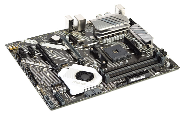
Все остальные элементы реализованы в минимальном числе, какие-либо дополнения и бонусы отсутствуют как класс. Комплект поставки спартанский, имеем базис или наиболее близкое приближение к этому типу. Вначале предлагаю изучить таблицу с перечнем ключевых характеристик.
| Модель | ASUS Prime X570-P |
|---|---|
| Официальная страница продукта в Сети | asus.com |
| Чипсет | AMD X570 |
| Процессорный разъём | AMD AM4 |
| Процессоры | AMD Series: Ryzen 3, Ryzen 5, Ryzen 7, Ryzen 9 |
| Память | 4 DIMM DDR4 SDRAM, максимум 128 ГБ: 2133/2400/2666/2800/2933/3000/3200/3400*/3466*/3600*/3733*/3866*/4000*/4133*/4266*/4400*(OC) |
| Слоты PCI-E | 1 x PCI Express 4.0 x16 (x16) — CPU 1 x PCI Express 3.0 x16 (x8) — APU 1 x PCI Express 4.0 x16 (x4) — X570 3 x PCI Express 4.0 x1 — X570 |
| M.2 | 1 x PCI Express 4.0 x4, SATA (Key M, 2242/2260/2280) — Ryzen 3rd Gen CPU 1 x PCI Express 3.0 x4, SATA (Key M, 2242/2260/2280) — Ryzen 2nd Gen CPU 1 x PCI Express 4.0 x4, SATA (Key M, 2242/2260/2280/22110) — X570 |
| Встроенное видеоядро (в APU) | Radeon Series: Vega |
| Видеоразъёмы | HDMI 1.4b |
| Количество подключаемых вентиляторов | 5x 4pin |
| Порты PS/2 | 1 (клавиатура/мышь) |
| Порты USB | 2 х 3.2 Gen2 (2 разъёма на задней панели, Ryzen 3rd Gen CPU) 2 х 3.2 Gen1 (2 разъёма на задней панели, Ryzen 2nd Gen CPU) 2 х 3.2 Gen2 (2 разъёма на задней панели, X570) 2 х 3.2 Gen1 (2 разъёма на задней панели, CPU/APU) 4 х 3.2 Gen1 (разъёмов на задней панели нет, X570) 5 x 2.0 (2 разъёма на задней панели, X570) |
| VR Ready | + |
| Serial ATA | 6 x SATA 6 Гбит/с (X570) |
| RAID | 0, 1, 10 (SATA, X570) |
| Встроенный звук | Codec — S1200A (Realtek) |
| S/PDIF | Разъём на плате (выход) |
| Сетевые возможности | Realtek 8111H (Gigabit Ethernet) |
| COM | 1 (внутренний) |
| LED Addressable Header | 1x Gen 2 |
| LED RGB Header | 2 |
| TPM | 1x SPI (14 pin) |
| UEFI | UEFI AMI BIOS, 256 Mb Flash ROM (25Q256JWEQ) |
| Форм-фактор | ATX |
| Размеры, мм | 305 x 244 |
| Дополнительные возможности | Aura Control, Armoury Crate, Fan Xpert 4, поддержка AMD 2-Way CrossFireX |
| Цена в рознице, $ | 200 |
Общая идея построения изделий на базе X570 рассматривалась в ходе знакомства с ASUS Prime X570-Pro.
Упаковка и комплектация
Коробка имеет минимально возможные габариты. На глянцевое и эффектное оформление не поскупились.
Фирменные технологии и решения выделены в качестве отличительных особенностей модели от ближайших конкурентов. Сзади находится фото устройства и детальный перечень наличествующих слотов с их описанием.
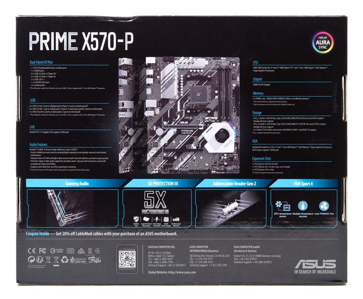
Помимо платы, в распоряжение покупателя попадёт:
- краткое руководство пользователя (на английском языке);
- QR-код DIY Guide, ведущий на страницу официального сайта, где размещена подробнейшая инструкция по сборке ПК;
- краткое многоязычное руководство пользователя по сборке ПК;
- дополнительный буклет с информацией о необходимости соблюдения ряда мер безопасности при сборке и эксплуатации системы;
- диск с драйверами и фирменным ПО;
- купон со скидкой для выполнения процедуры оплетения проводов (раундинга);
- крепёжный винт и стойка для устройств формата M.2 — два комплекта;
- два кабеля SATA 6Gb/s, один из которых с Г-образным разъёмом на одном из концов;
- заглушка для корпуса, обычного исполнения — с тиснением символов и иконок обозначения гнёзд;
- удлинитель для подключения управляемой светодиодной ленты.
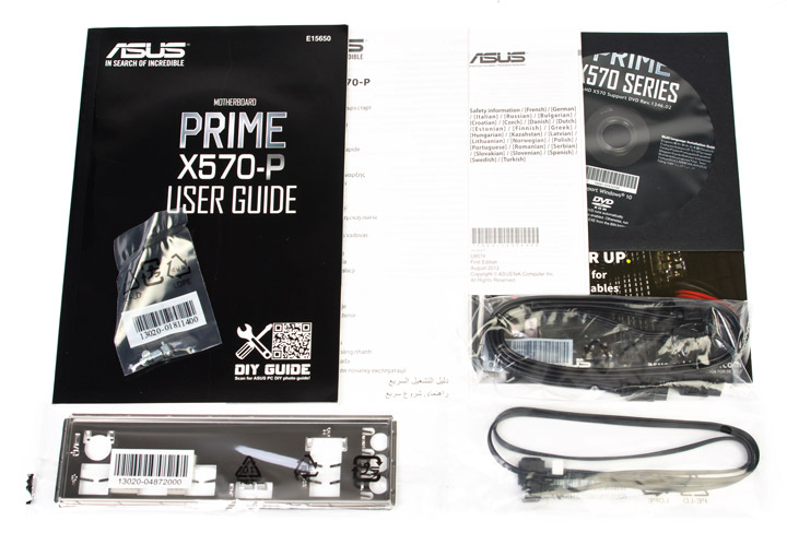
Внешний вид
Кроме броского, но строгого оформления в монохромных оттенках, выделить нечего. Не использовали даже накладку для участка с портами ввода-вывода на задней панели! Вспомогательные индикаторы состояния ПК, кнопки, переключатели и прочие дополнительные элементы полностью отсутствуют. Предусмотрено девять отверстий для крепления модели в корпусе, размер её соответствует формату ATX, я для питания процессора предусмотрено два гнезда.
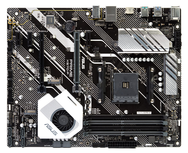
Тыльная сторона фактически полностью освобождена от электронных компонентов, в ходе монтажа вряд ли возникнут трудности. Радиаторы закреплены посредством винтов.
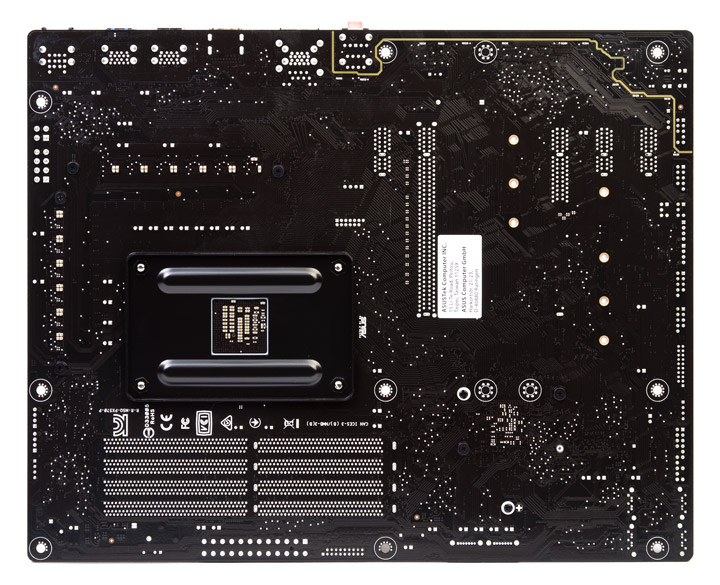
Область с подсветкой находится справа вверху от вентилятора, с привлечением габаритной видеокарты она окажется фактически незамеченной. Здесь используются одноцветные светодиоды в числе четырёх штук: два синих, один красный и один белый. Они распаяны непосредственно на плате.
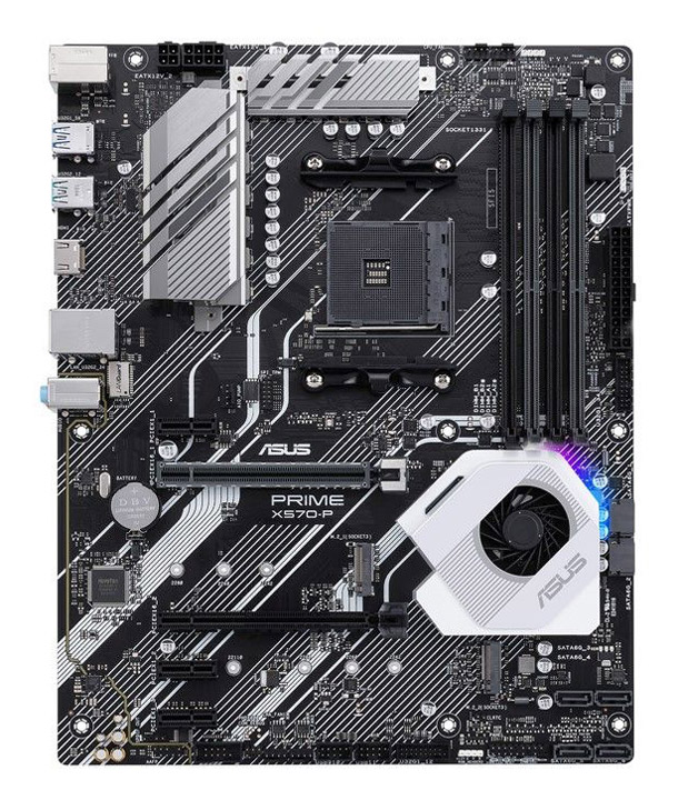
Идея организации охлаждения хаба в точности воспроизводит конструкции, виденные в других среднеценовых моделях от ASUS, побывавших прежде в нашей лаборатории. Вентилятор радиального типа проталкивает вниз воздух, захватываемый сверху.
Тот проходит через гребёнку из достаточно удалённых друг от друга рёбер, этим старались минимизировать создание неприятных акустических эффектов. Исполнение теплосъёмника, тип вентилятора и его подключение к плате абсолютно идентичны другим устройствам.
Оба посадочных места под накопители в формате M.2 не сопровождаются предустановленными радиаторами. Верхнее ограничивает длину монтируемого устройства до 80 мм, тогда как с нижним таких трудностей уже не будет. Оба поддерживают как интерфейс SATA, так и PCI-E, последнего, четвёртого поколения.
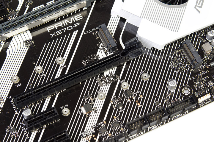
Имеется пара продольных слотов SATA.
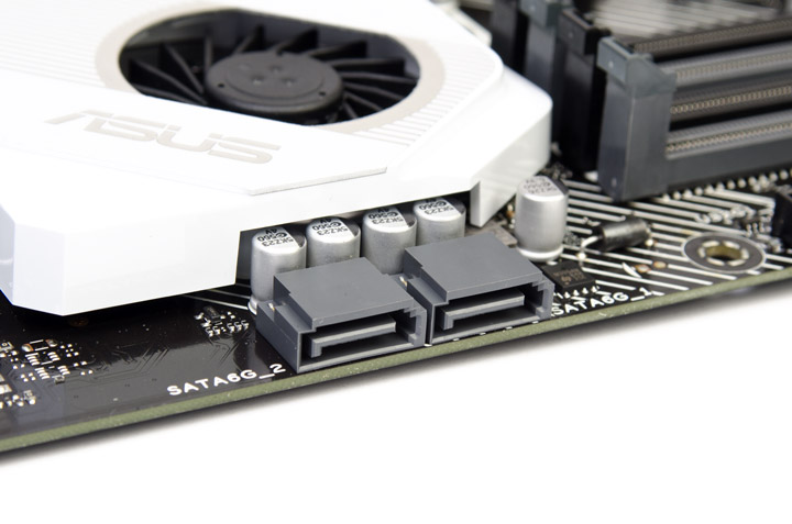
Ещё четыре находятся в правом нижнем углу, они — поперечные.
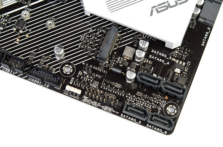
Корпусные кабели помогут работе трёх (!) гнёзд USB второй ревизии и четырёх версии 3.2 Gen1. Площадка под симметричное, последнего поколения (3.2 Gen2), отсутствует.
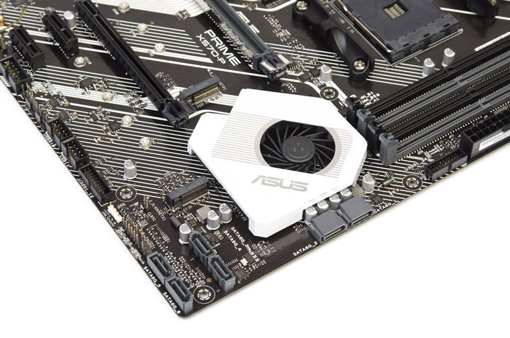
Серое, армированное гнездо PCI-E взаимодействует с шестнадцатью процессорными линиями, а остальные — с хабом AMD X570.
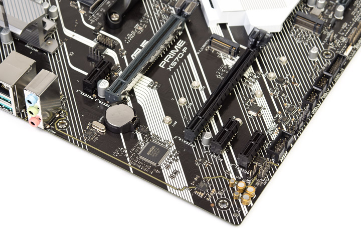
Зона распайки звукового кодека буквально повторяет почерк из ASUS TUF Gaming X570-Plus. Правда тут нет экранирующего колпака, да и специализированные конденсаторы не все одинаковые, словом, упростили как смогли.
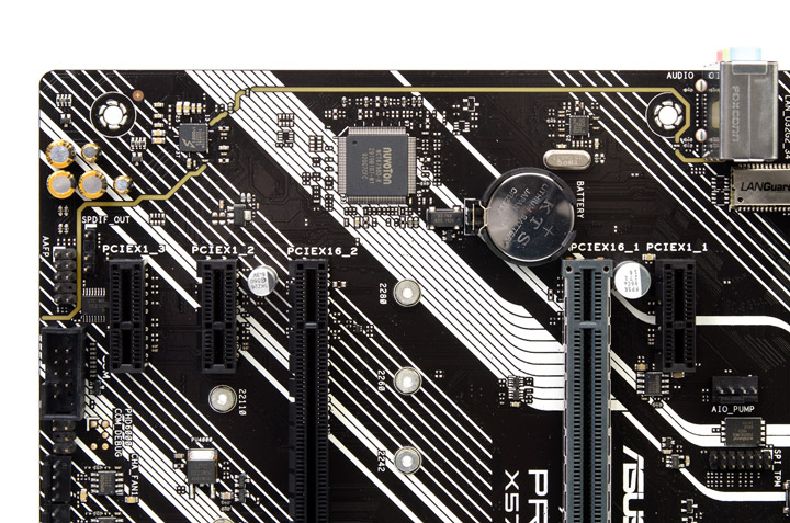
А вот охладители в силовой подсистеме скорее лучше, чем у более дорогой модели. Винтовой крепёж, больший вес и размеры, в сумме — интересный ход. Однако угрозы совместимости даже с двухсекционными «башнями» здесь нет, всё выполнено в разумном ключе.
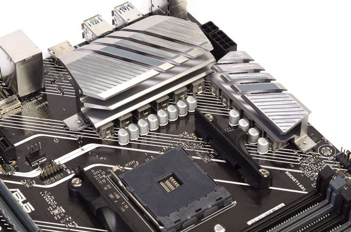
Для реализации стабилизатора использовались уже хорошо знакомые по прошлым обзорам элементы: ШИМ-контроллер — ASP1106GGQW, транзисторные сборки типа DrMOS — SiC639 от Vishay Intertechnology. Всего их двенадцать, констатирую приём удвоения числа элементов в составе каждой «фазы». Общая структура имеет вид 4+2 штуки, соответственно, для напряжений CPU и SOC.
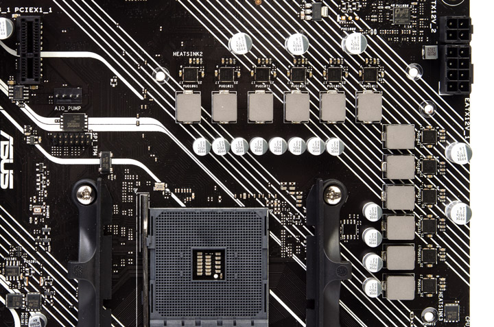
Небольшие замечания есть к площади термопрокладок на большом радиаторе. Если с транзисторами не лучший отпечаток можно списать на конкретный экземпляр платы, но для дросселей явственно видна лёгкая нехватка длины, хотя это уже скорее придирки, потому как теплопередача в целом организована хорошо.
Набор портов на задней панели достаточно простой, но назвать его бедным язык не повернётся. Всё же восемь разномастных выходов USB, да ещё и на приличном отдалении друг от друга, — неплохой арсенал, а ведь ещё есть и PS/2. За симметричным портом необходимо обращаться к более статусным устройствам, как и к адаптеру беспроводных сетей, предустановленному здесь же. Для него не оставляли посадочное место, ни около задней панели, ни где-то в середине платы. Наиболее прискорбно выглядит комбинация аудио- и видеовыходов — их суммарно лишь четыре штуки, максимально простой тандем. Заглушка в комплекте не отягощена украшениями и представляет собой классический «слепок» из листового металла.
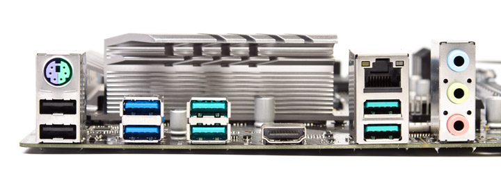
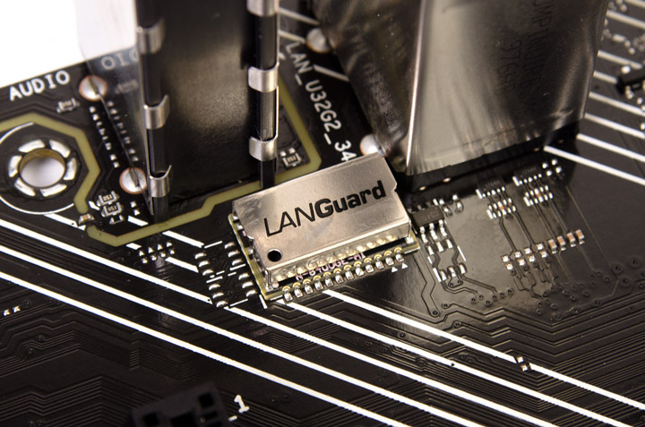
Возможности UEFI
Обновление прошивки займёт немало времени, я использовал интегрированную в состав UEFI утилиту Ez Flash.

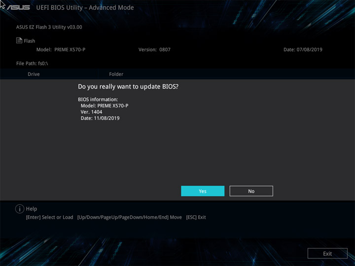
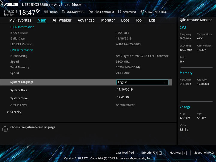
Ez Mode — упрощённый режим работы с платой. Тут собраны сведения о компонентах и режимах их работы. Ещё можно уточнить актуальность даты и времени, активировать XMP для ОЗУ (режим называется D.O.C.P.), определиться с приоритетом загрузочных устройств. Интерактивная форма с указанием алгоритмов работы всех охладителей открывается в отдельном окне. Управлять вентилятором на хабе нельзя.
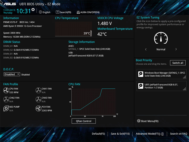

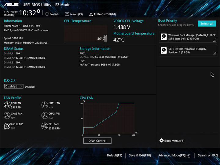
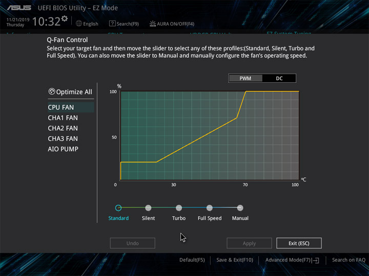
Полный доступ к настройкам реализован в режиме Advanced Mode. Первый раздел с названием My Favorites предназначен для формирования списка часто используемых пунктов для ускоренного к ним доступа, будет полезен при разгонных экспериментах. В разделе Main можно сменить локализацию интерфейса.
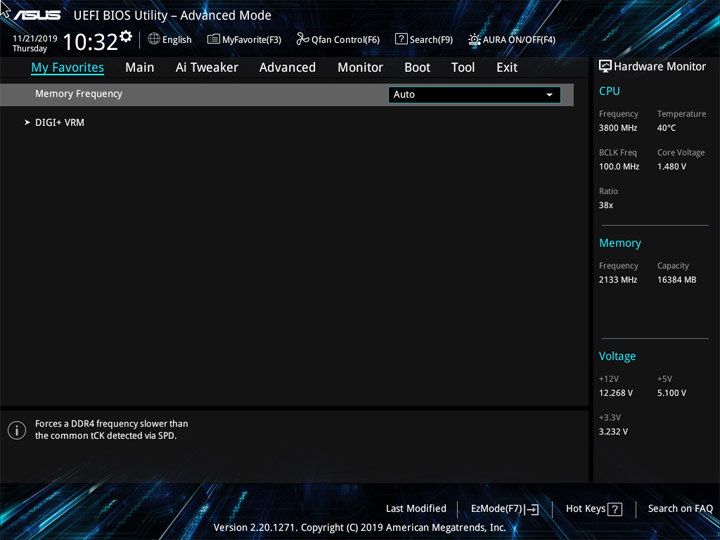

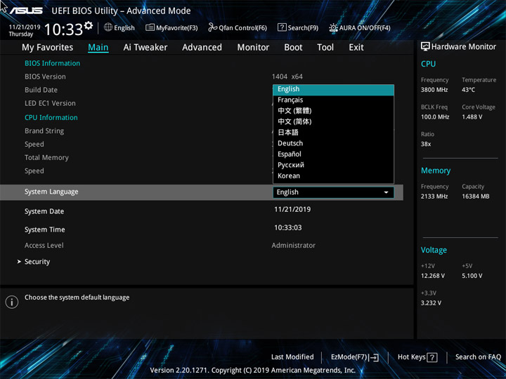
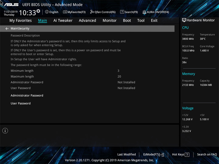
Разгонный инструментарий радует большим числом доступных для редактирования напряжений. Базовую частоту менять негде, готовый фирменный профиль разгона процессора всего один (OC Tuner). Подстройка работы процессора может проходить при участии пунктов Performance Enhancer, Performance Bias, а ещё с привлечением редактирования PBO, для чего предусмотрено отдельное подменю. Новая версия AGESA явила подраздел CPU Core Ratio (Per CCX). Частоту ядер можно будет задать более предметнее, а не одномоментно для всего ЦП.


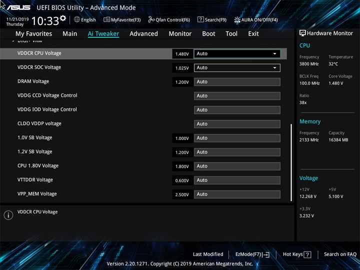
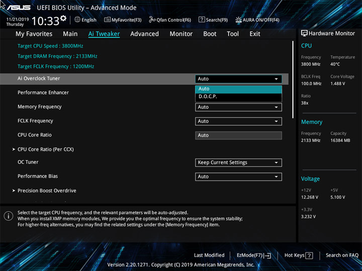
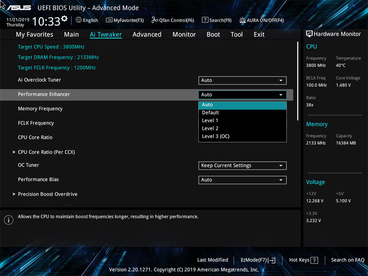
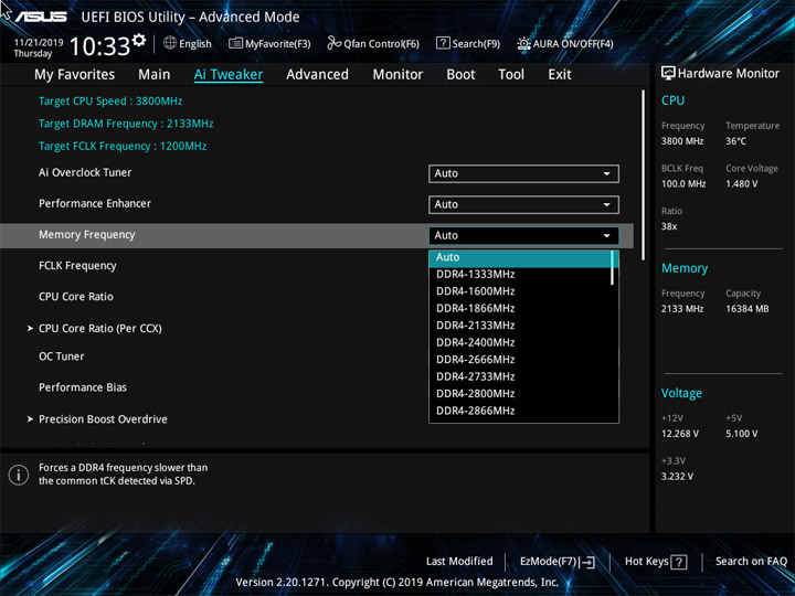
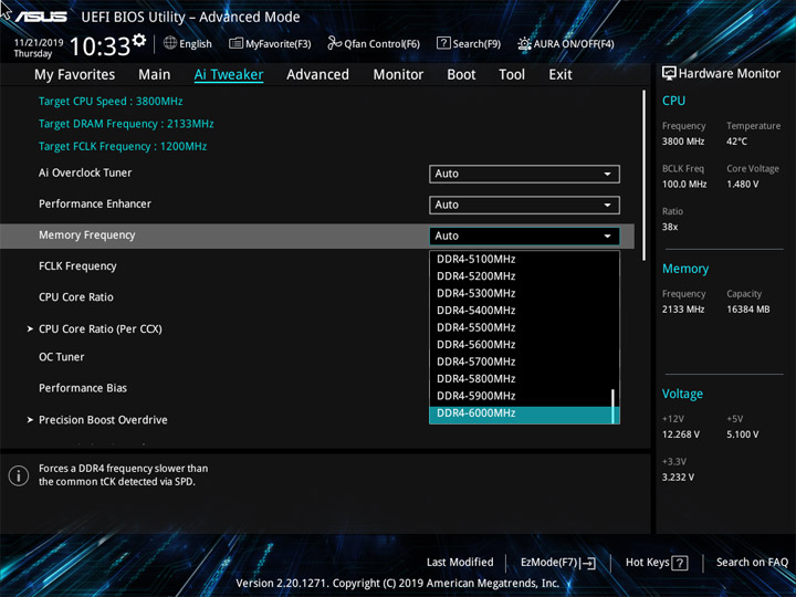
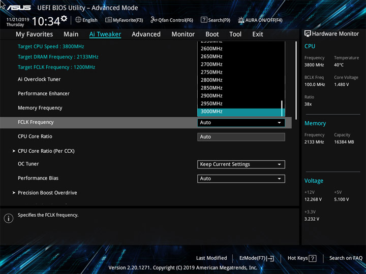
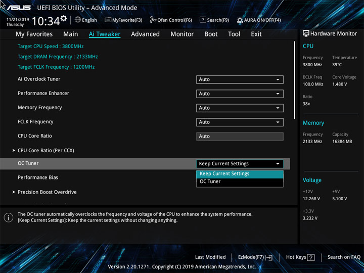
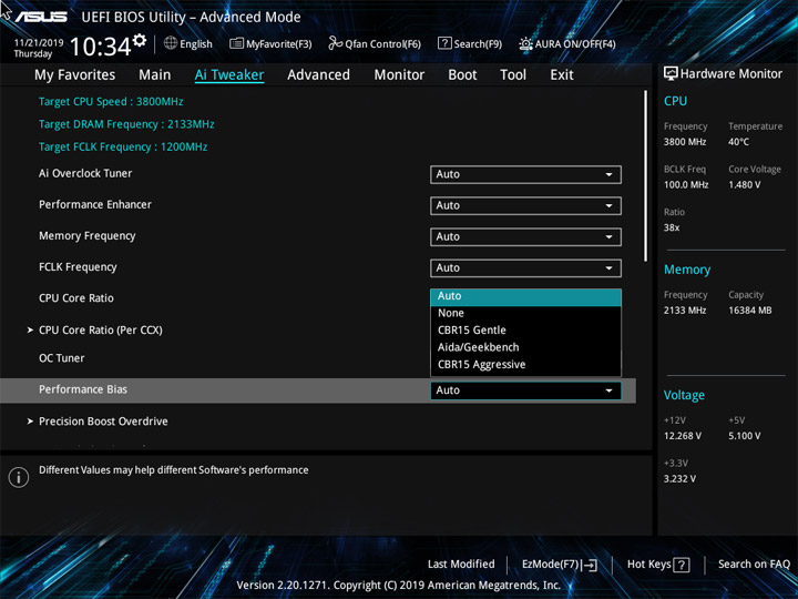
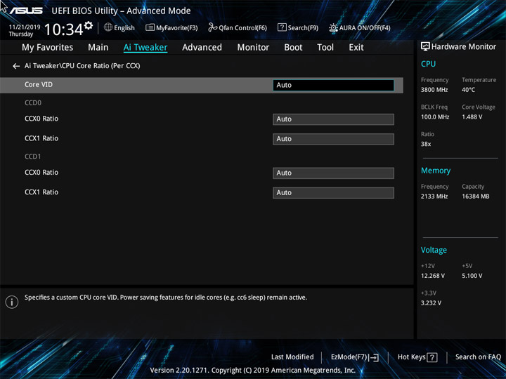
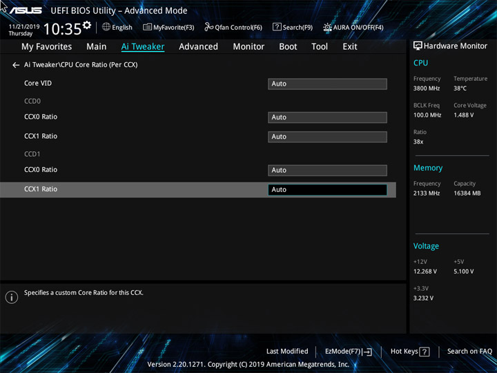
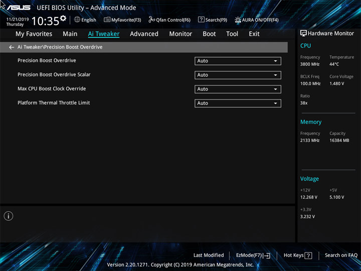
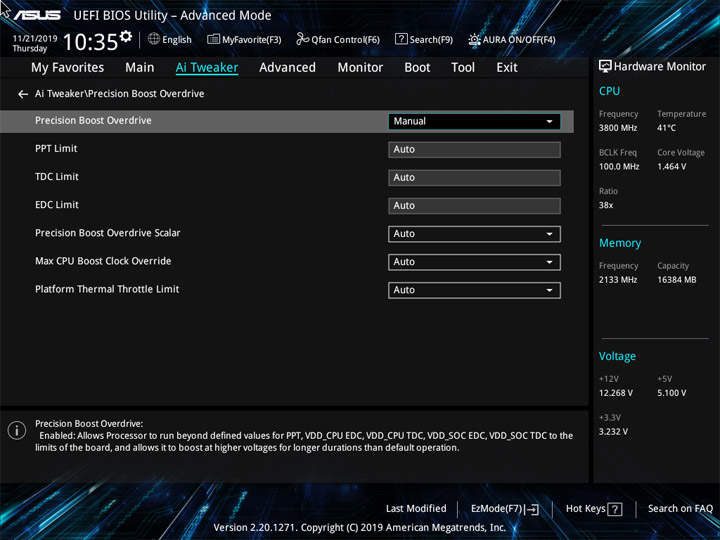
Наладка ОЗУ включает доступ ко множеству задержек и сопутствующих параметров, нет никаких усечений.
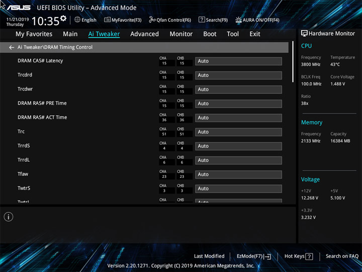
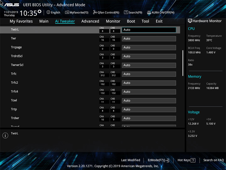
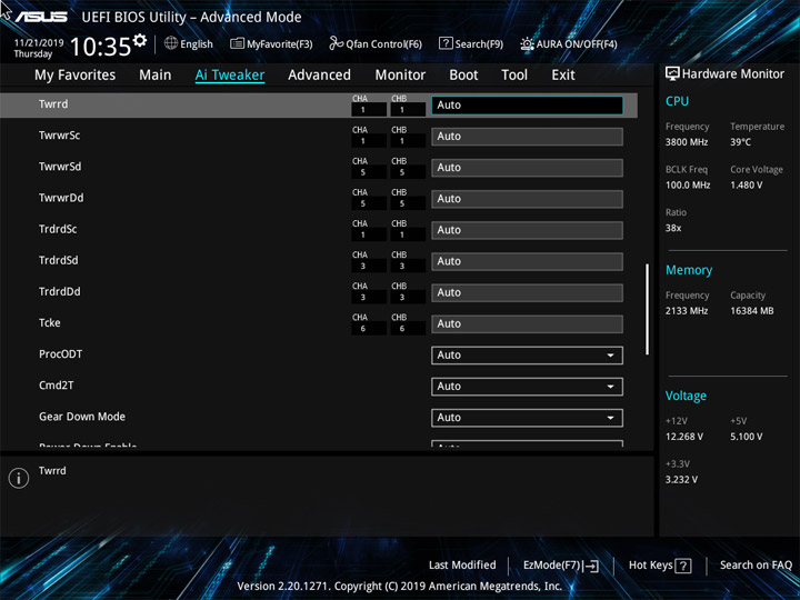
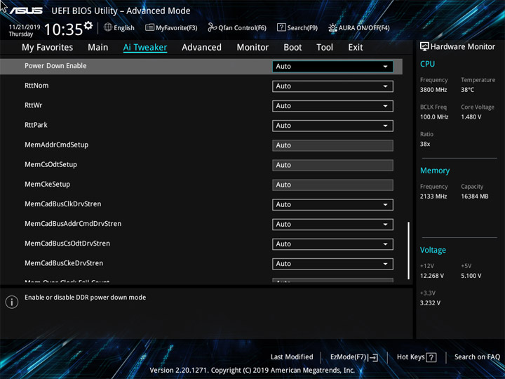

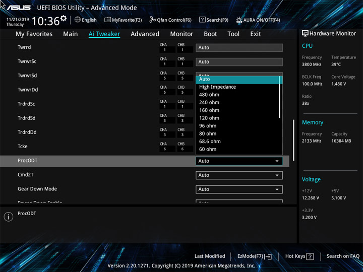
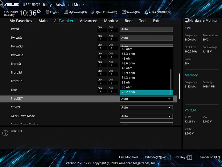
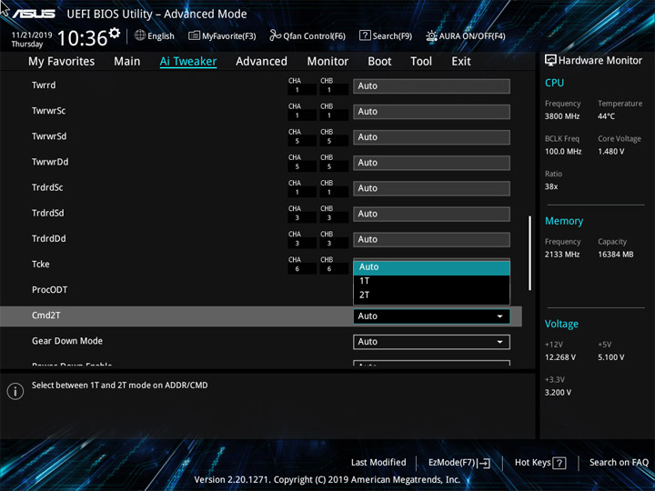
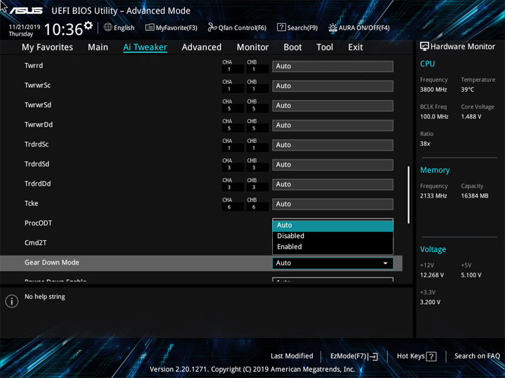
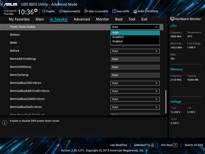
Упрощения коснулись подраздела, ответственного за VRM. Имеется возможность изменить задающую частоту работы ШИМ, а также меньшее, чем обычно, число профилей LLC. Для смены уровня напряжений CPU и SOC есть два способа. Предел для увеличения напряжения на модулях памяти — 1,8 В.

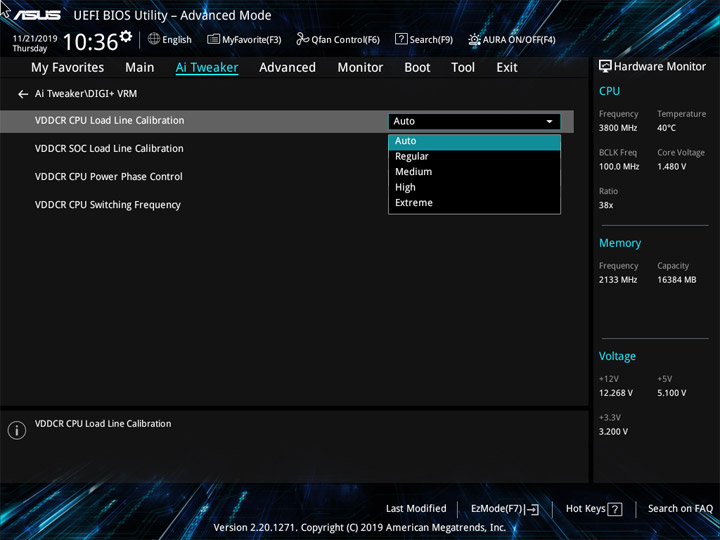
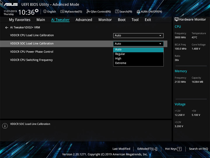
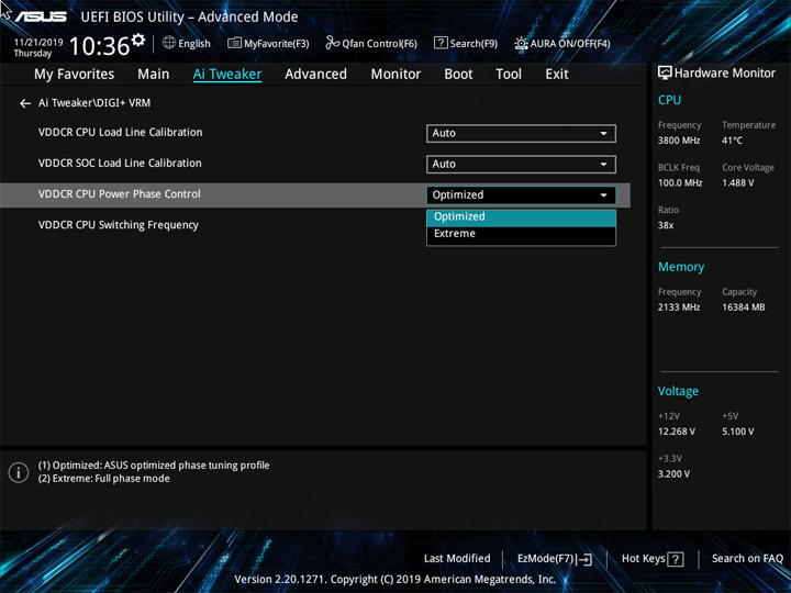
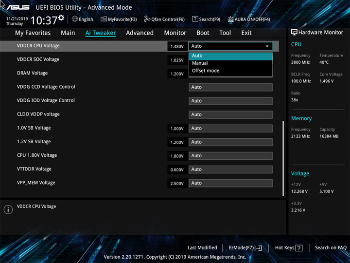
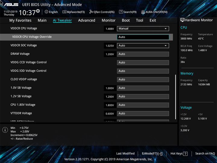
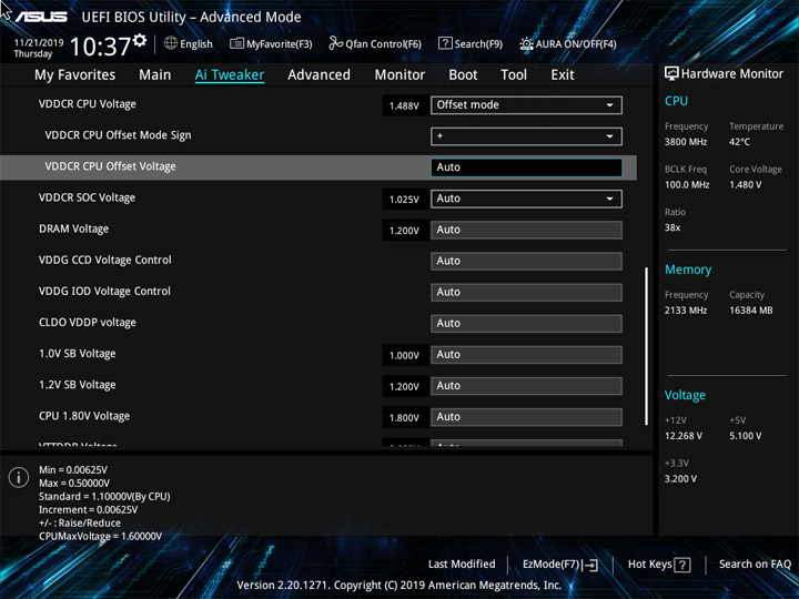
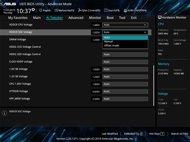
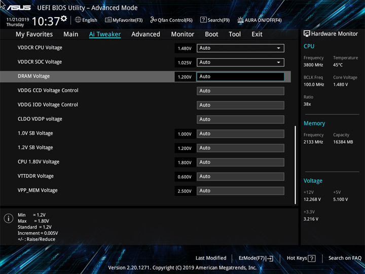
Наиболее важные системные величины, их пределы и шаг изменения собраны в таблице.
| Параметр | Диапазон регулировки | Шаг |
|---|---|---|
| BCLK Frequency (МГц) | – | – |
| CPU Core Ratio (Multiplier) | 28–63,75 | 0,25 |
| VDDCR CPU Load Line Calibration | Auto/Regular/Medium/High/Extreme | |
| VDDCR CPU Voltage Override (В) | 0,75–2,00 | 0,00625 |
| VDDCR CPU Voltage Offset (В) | (+/–) 0,00625–0,5 | 0,00625 |
| VDDCR SOC Load Line Calibration | Auto/Regular/High/Extreme | |
| VDDCR SOC Voltage Override (В) | 0,75–1,80 | 0,00625 |
| VDDCR SOC Voltage Offset (В) | (+/–) 0,00625–0,5 | 0,00625 |
| FCLK Frequency (МГц) | 666–1333 1366–2500 2550–3000 |
133,33 33,33 50 |
| Memory Frequency (МГц) | 1333–2666 2733–5000 5100–6000 |
266,7 66,7 100 |
| DRAM Voltage (B) | 1,2–1,8 | 0,005 |
| CPU 1.80V Voltage (В) | 1,8–1,85 | 0,05 |
| 1.0V SB Voltage (В) | 1,0–1,05 | 0,05 |
| 1.2V SB Voltage (В) | 1,2–1,25 | 0,05 |
Advanced — рубрика с настройками для остальных подсистем. Работа четырёх светодиодов на плате ничего кроме отключения не подразумевает. В противном случае они постоянно работают, никаких эффектов для них не предусмотрено. Aura ON/OFF — пункт для добавочной инфраструктуры, у случае её использования, конечно же.
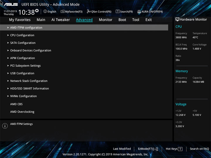
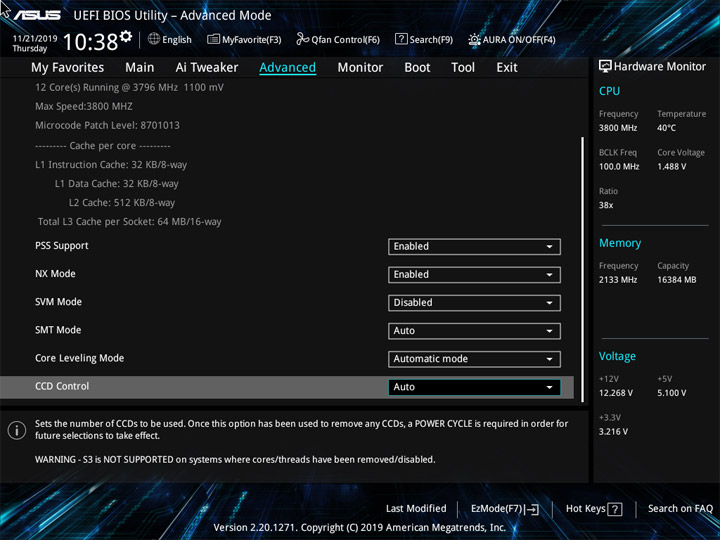
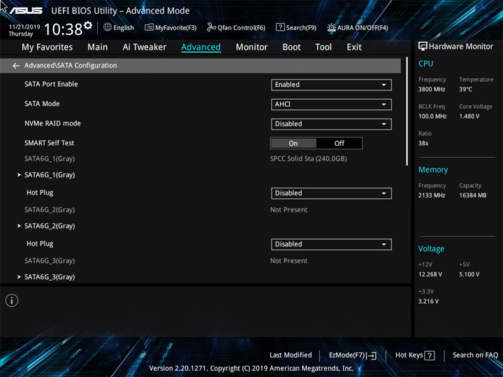
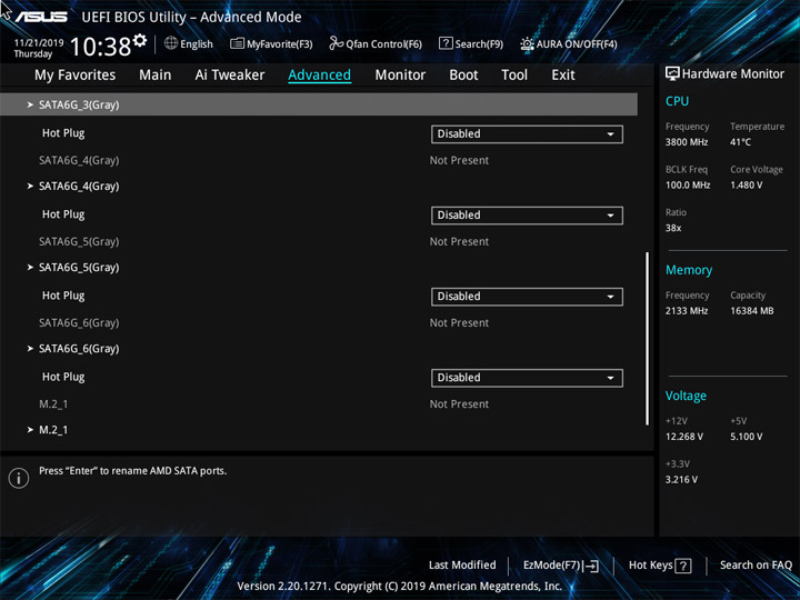
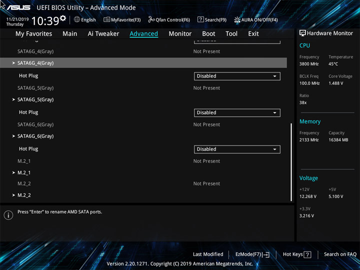
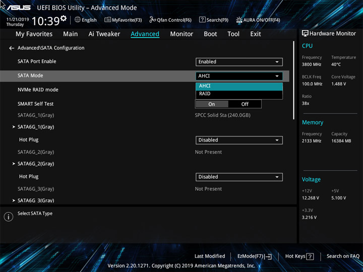
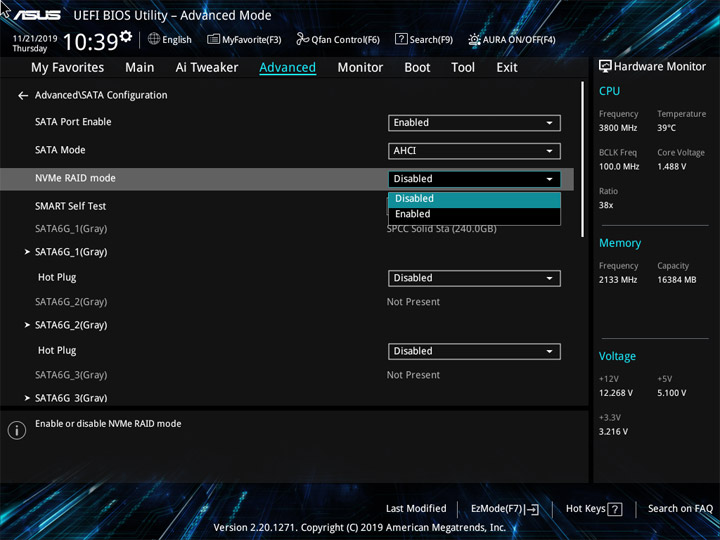
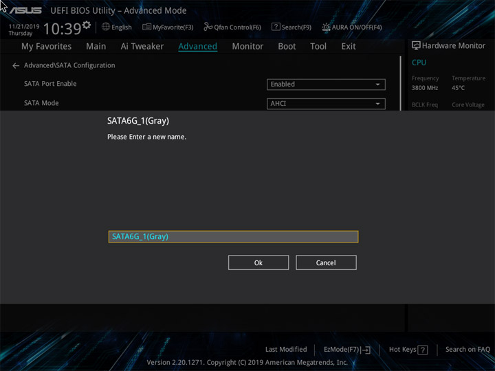
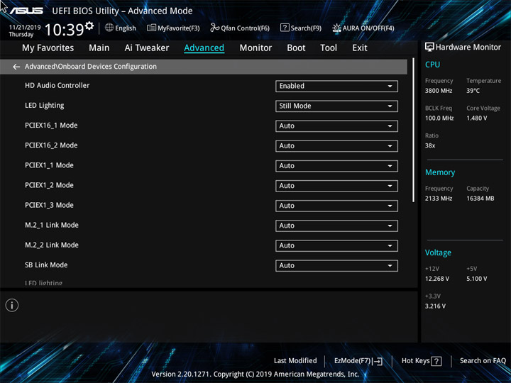
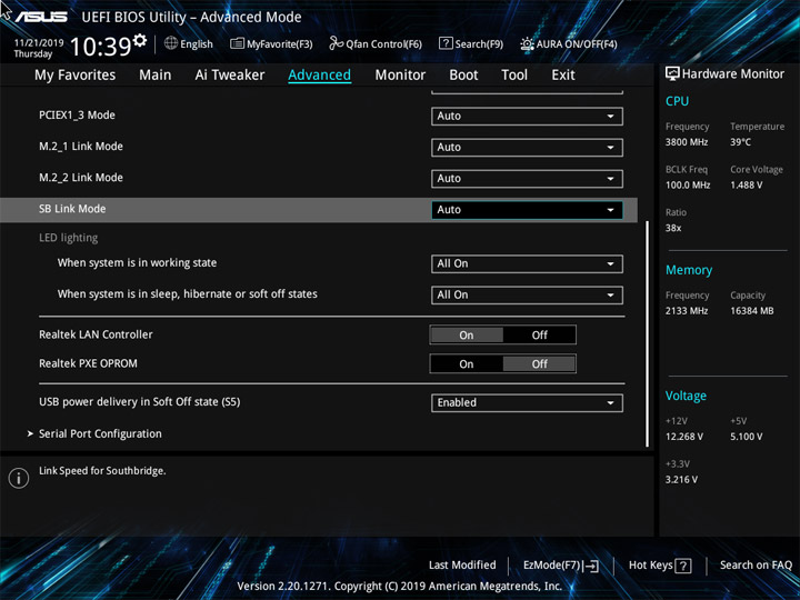

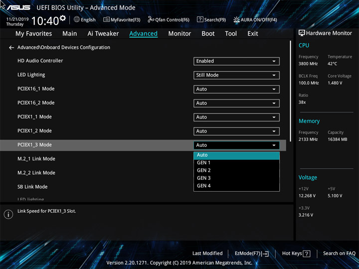
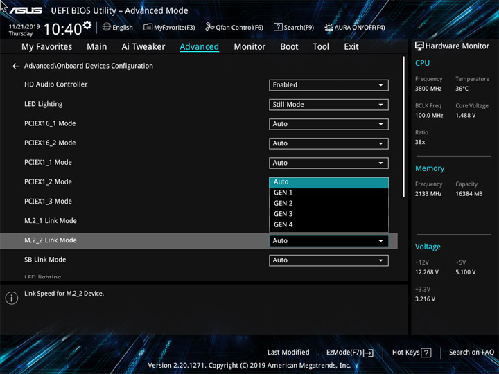
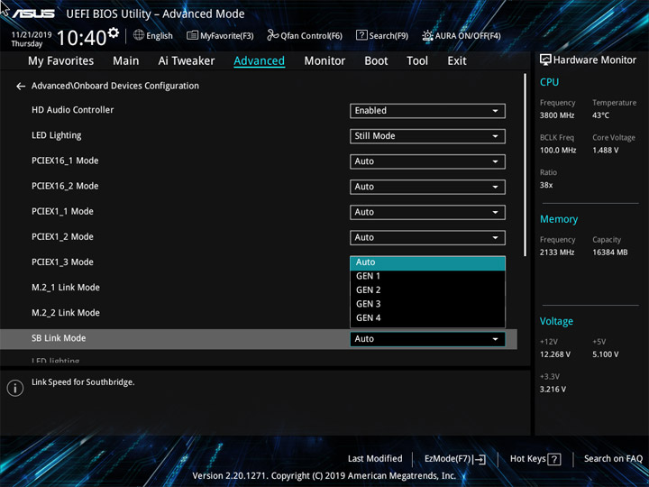
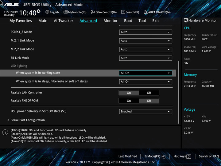
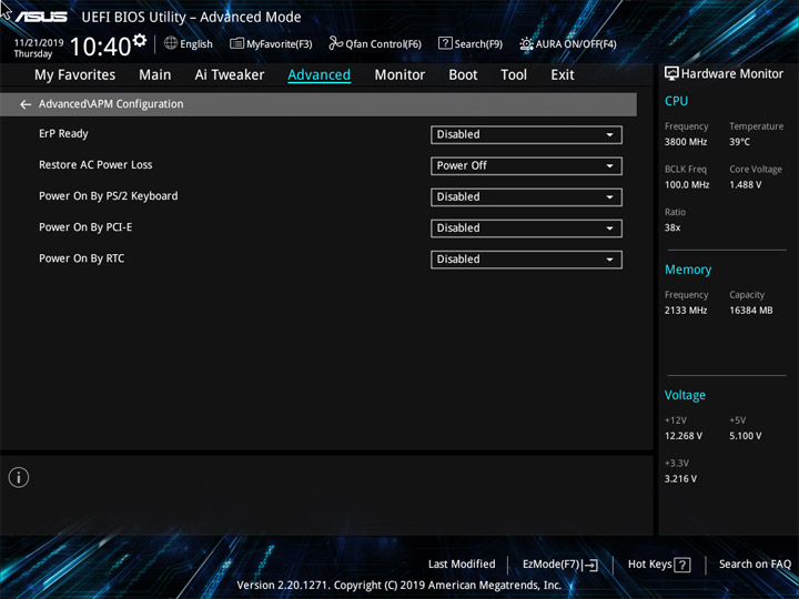
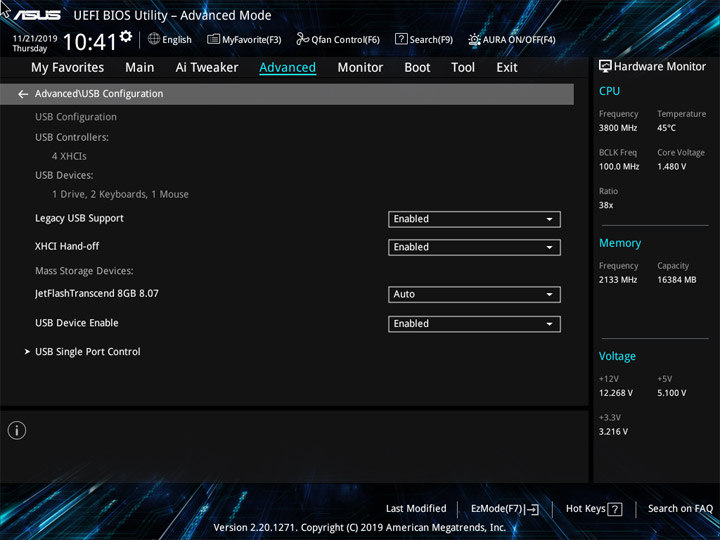
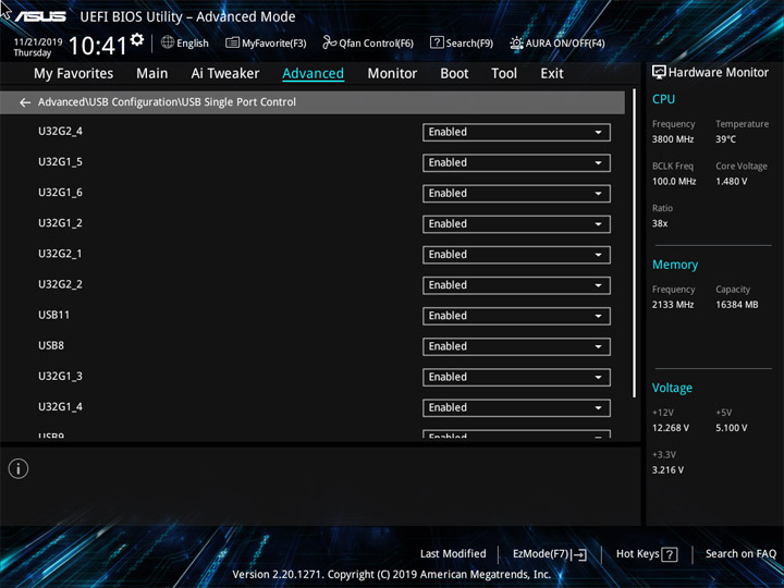
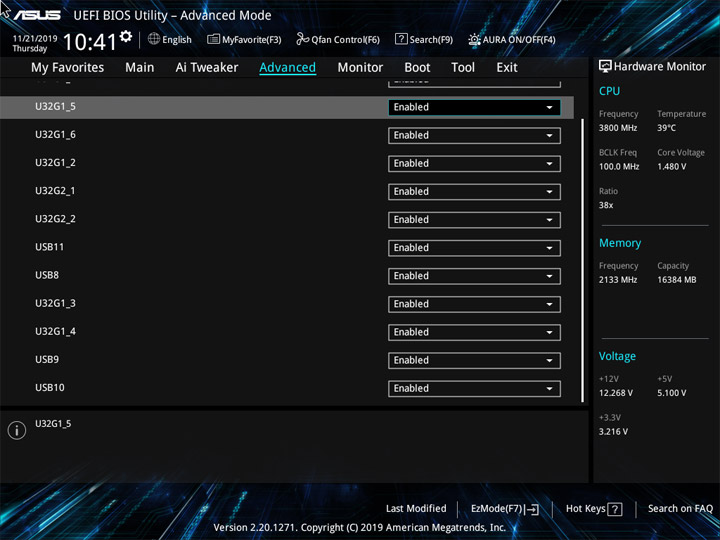
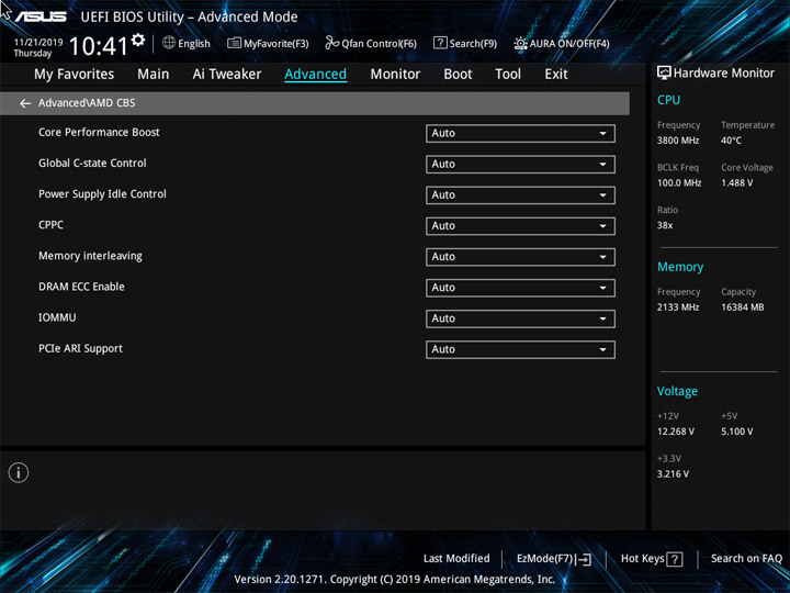
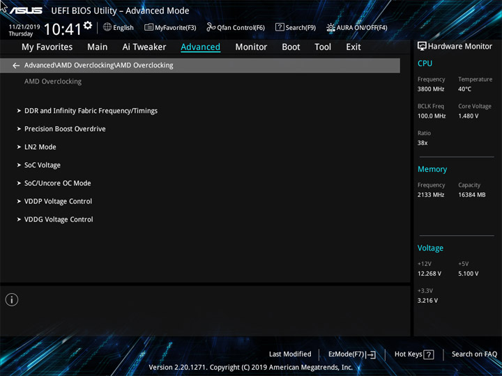
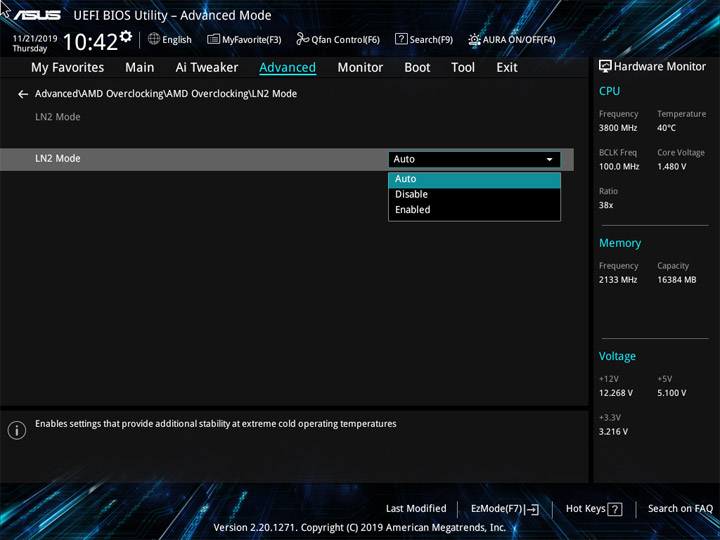
Имеются три показателя температур, два их которых связаны с ЦП и отличаются один от другого на 10 градусов. Использование добавочного сенсора не предусмотрено. Всего контролировать работу можно у пяти устройств, куда не входит вентилятор на хабе. На всех площадках допускается ручной выбор способа изменения скорости работы подключённых устройств (PWM либо DC). Механизм Qfan Tuning определяет нижний рабочий порог для системных охладителей, без него предел окажется равным «60 %» без возможности его понижения.
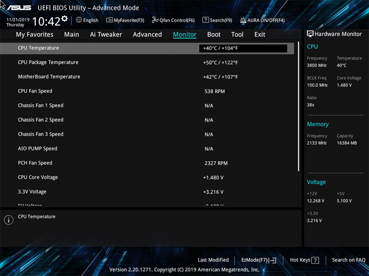
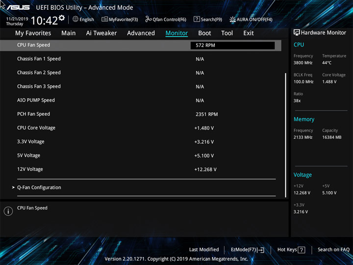
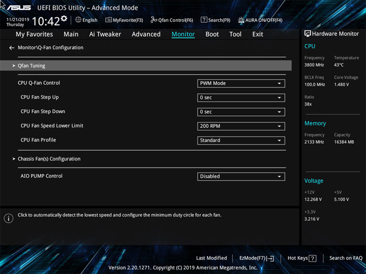
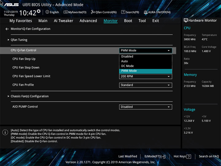
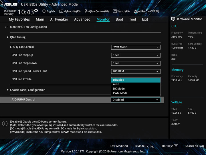
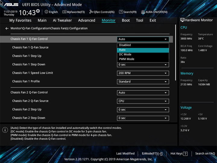
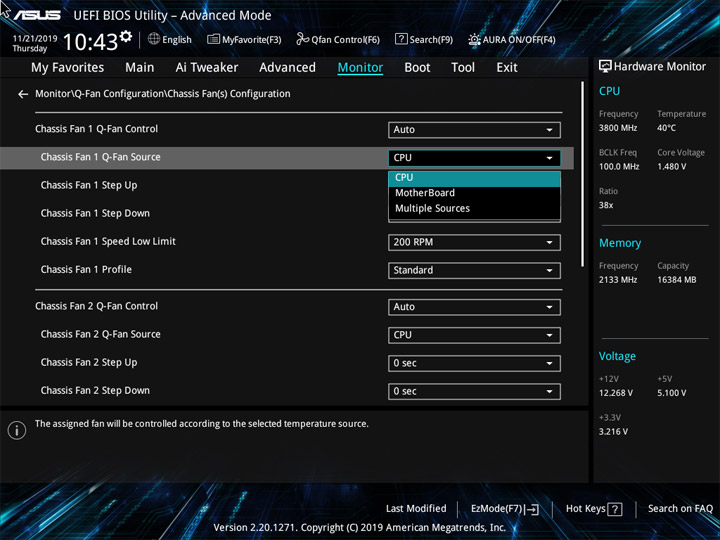
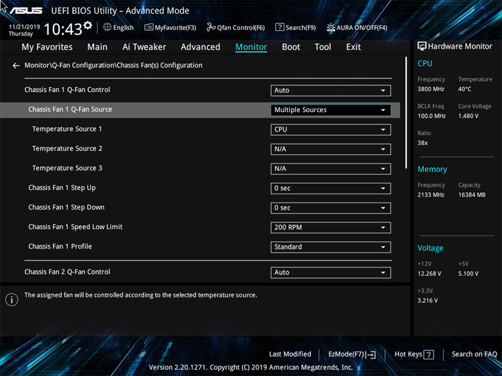
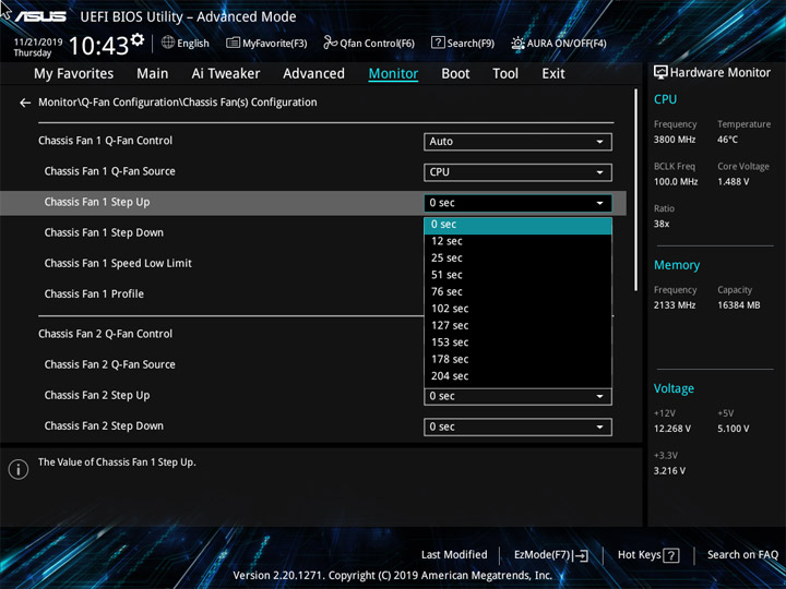
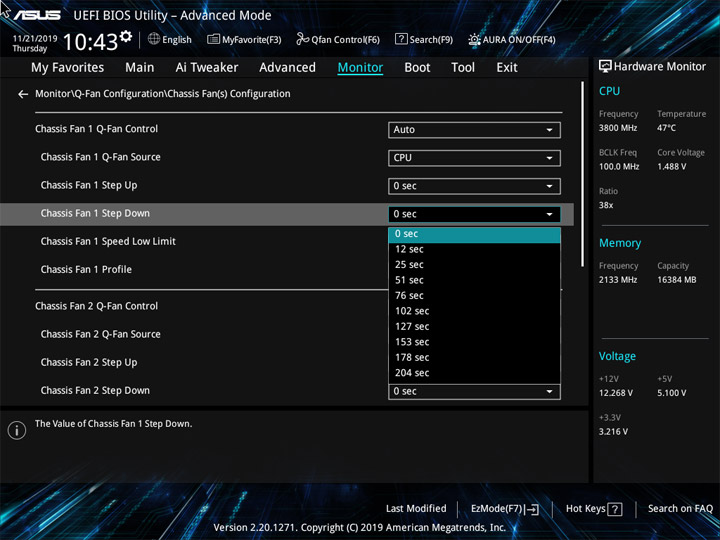
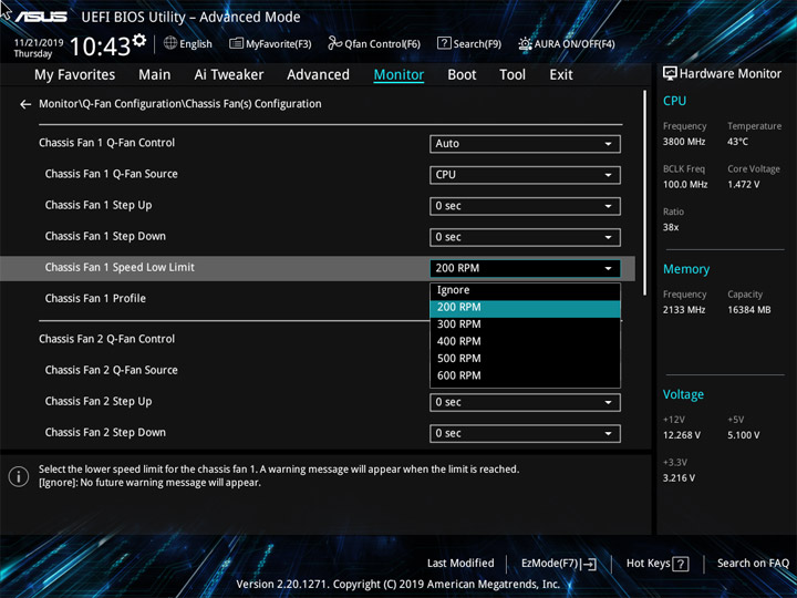
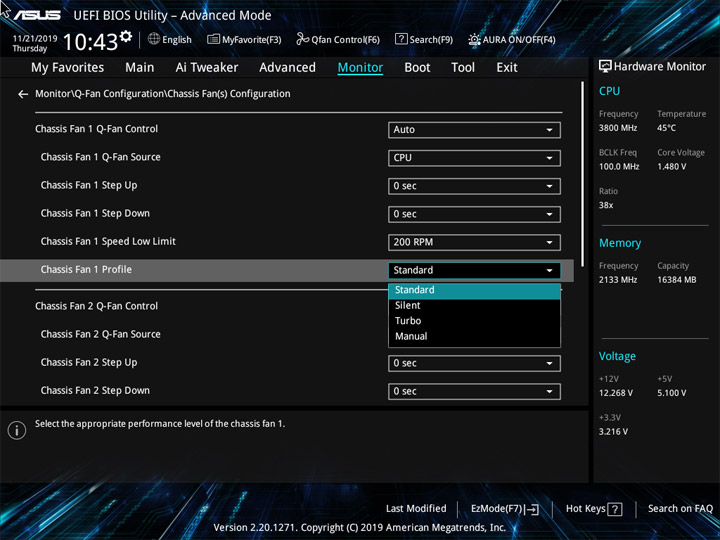
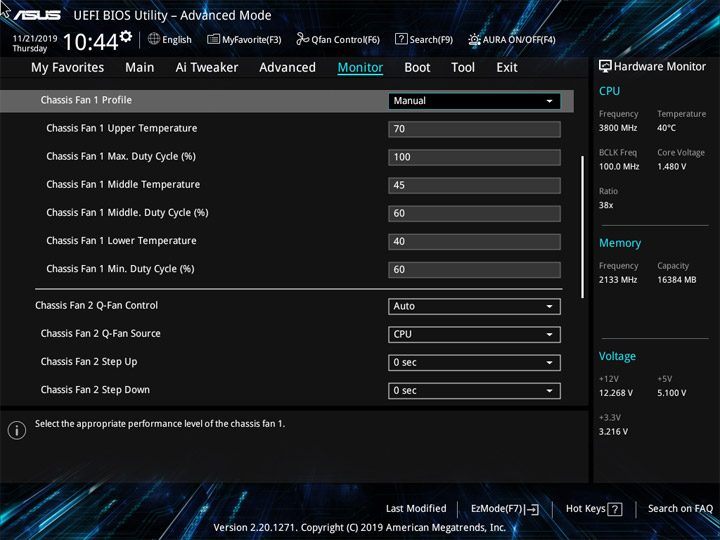
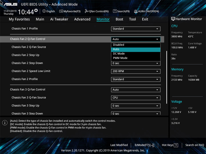
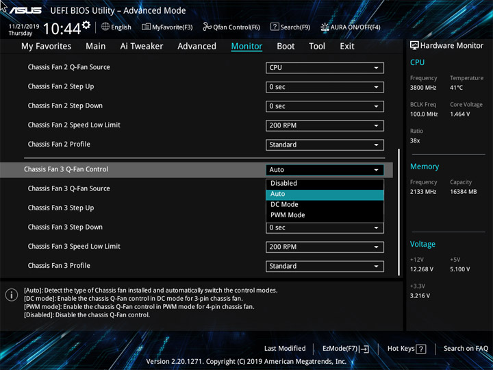
Наиболее длительным этап инициализации оборудования будет после обнуления настроек. С уже готовыми, прежде сохранёнными, процедура проходит намного живее. При экспериментах с разгоном этот промежуток времени может заметно меняться в разные стороны. CSM изначально деактивирован и потому дополнительно ускорить систему на этом этапе вряд ли получится.
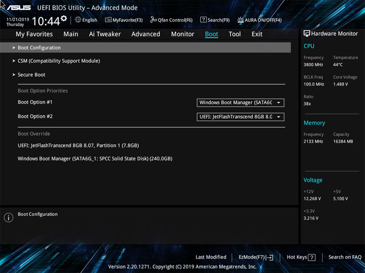
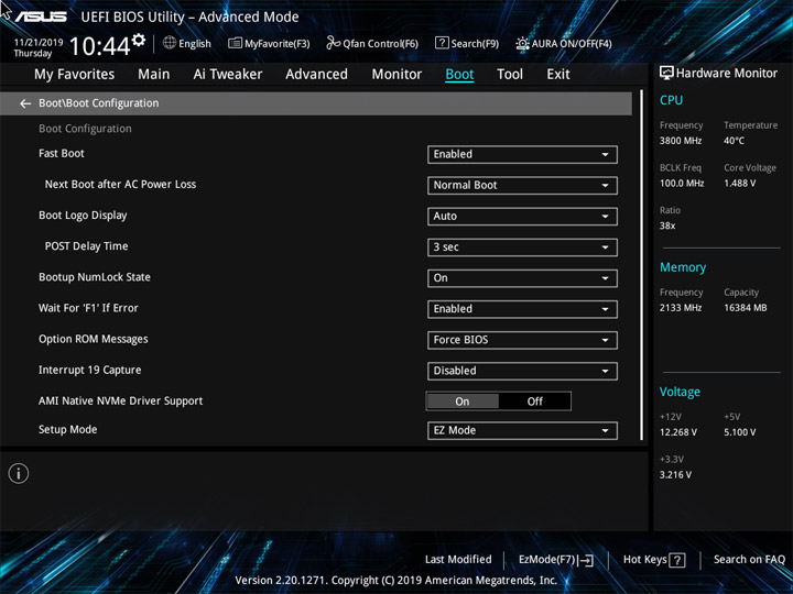
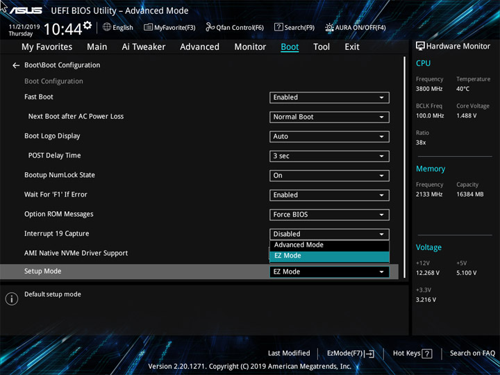

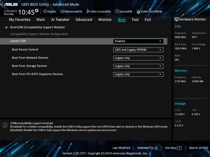
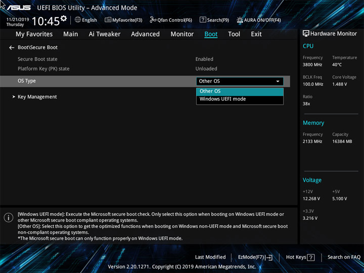
Поддержка Armoury Crate есть теперь даже здесь, словом, все платы на базе X570 у ASUS оказались в списке поддержки этого программного комплекса. Также имеется обозреватель возможностей DRAM и механизм по хранению и загрузке настроек при содействии восьми профилей либо стороннего носителя. Ускоренный поиск настроек доступен по нажатию F9.
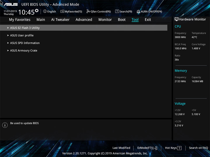
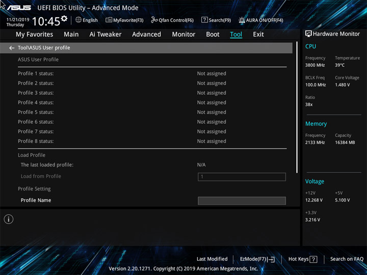
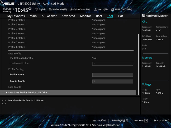
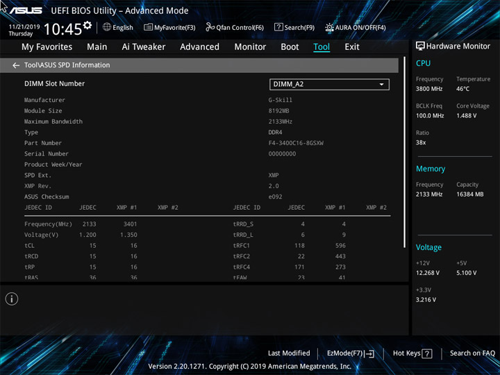
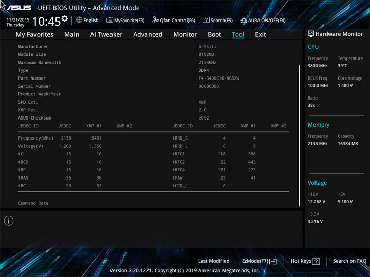
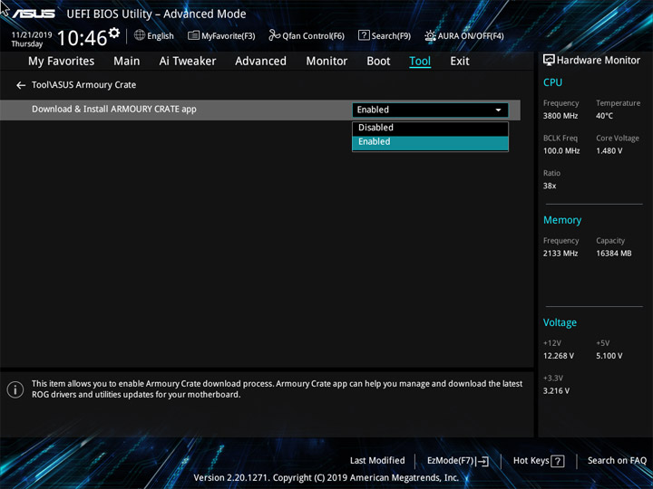
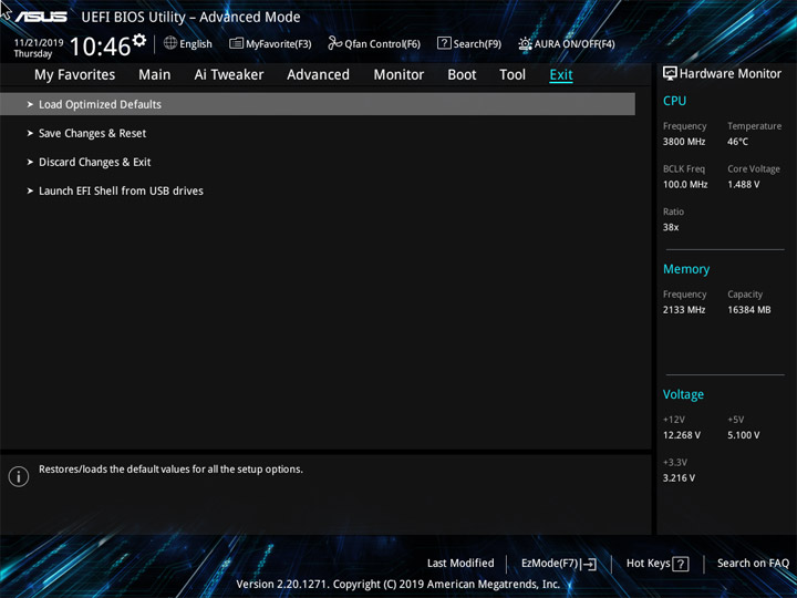
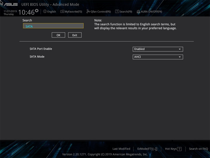
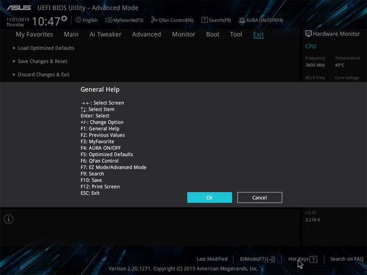
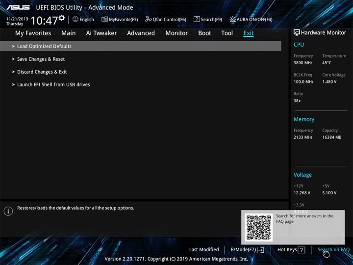
Появление новых пунктов в меню UEFI при использовании APU можно оценить на примере модели ASUS ROG Strix X570-I Gaming.
Комплектное ПО
Список прост, насколько это возможно вообще. Нет никаких бонусных утилит, Звук и Сеть остались без них.
| Программное обеспечение | |
|---|---|
| Фирменное | AI Suite 3 (Ai Charger, EZ Update, PC Cleaner, Performance and Power Saving Utilities, System Information), Armoury Crate |
| Дополнительное | AMD StoreMI, WinRAR (пробная версия на 40 дней) |
Использование Armoury Crate проходит без фирменной темы под серию продуктов Prime, возможно, она появится позже. При инсталляции видны фирменные цвета семейств ROG, а по ходу работы с установкой обновлений они меняются на тона, свойственные продуктам серии TUF Gaming.
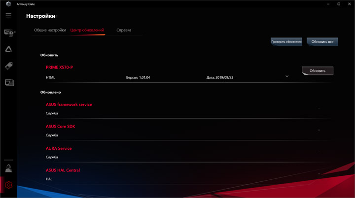
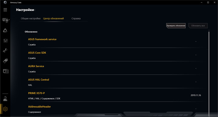
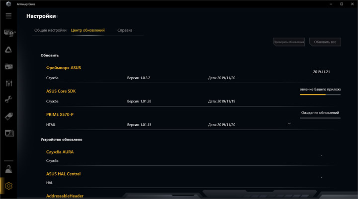
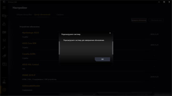
Полезными могут стать мастера по установке и обновлению драйверов и утилит, они раздельные. Не было проблем с их использованием.
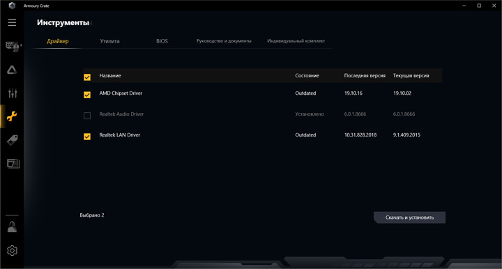
Наладка работы подсветки будет касаться только стороннего оборудования, как я уже отмечал разделом выше. Функциональный спектр Aura Sync ничем не отличается от более статусных устройств.
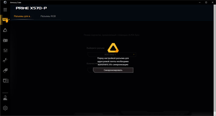
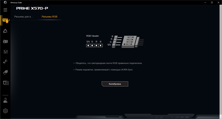
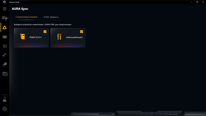
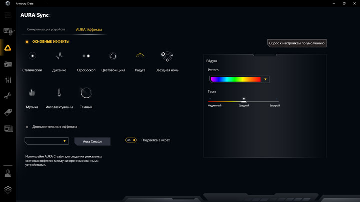
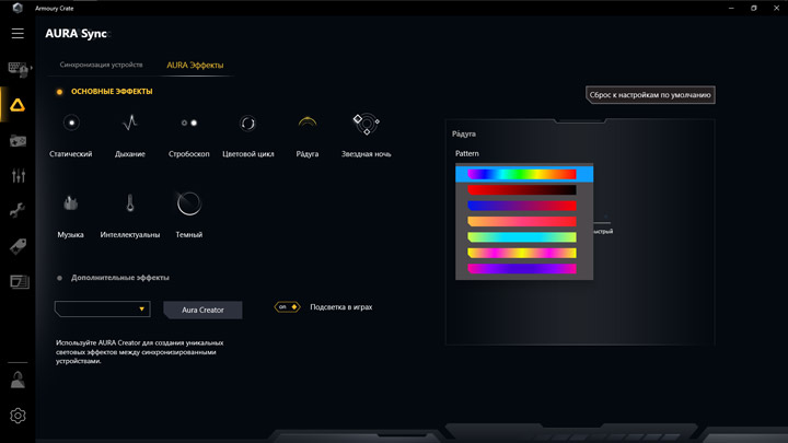
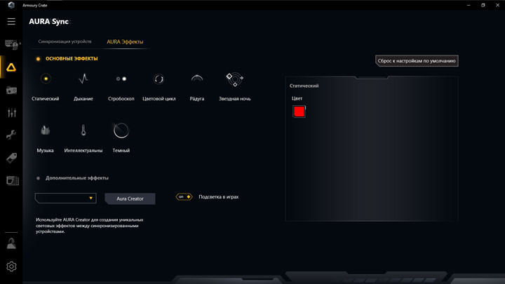
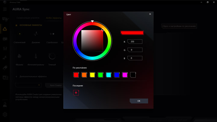
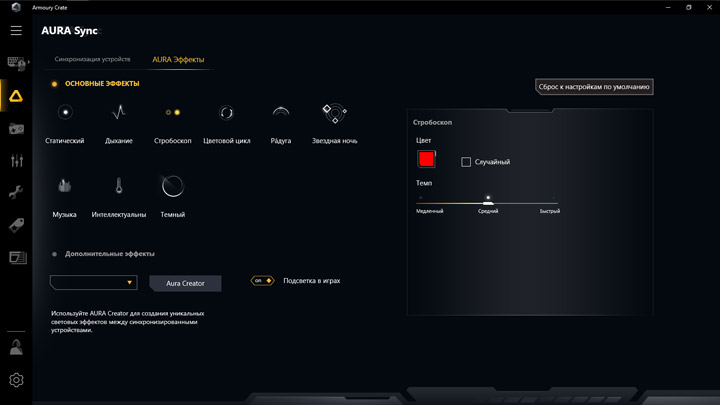
Комплекс Armoury Crate совершенствуется на глазах. Появился пункт Игровая Библиотека, но несколько игр, установленных не на системном разделе посредством Steam, он не смог идентифицировать, потому, пока что, идея этой страницы останется за кадром.
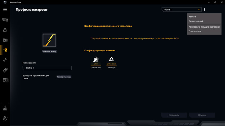
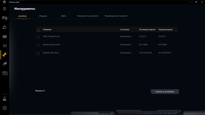
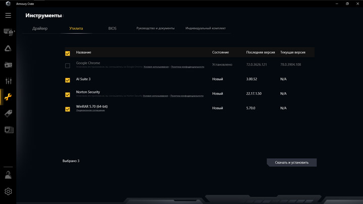
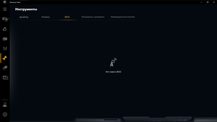
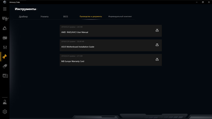
Управление параметрами платы и вентиляторами до сих проходит при участии Ai Suite 3, состав которого тоже минимален. Мастер по наладке ПК DIP5, свойственный более дорогим устройствам, отсутствует, каждый из инструментов потребуется использовать индивидуально. Все они давно знакомы приверженцам марки ASUS. Отмечу наличие старшей версии Fan Xpert, а значит управление вентиляторами будет включать расширенный диапазон контроля в области низких частот вращения крыльчаток. Влиять на скорость работы охладителя хаба отсюда также нельзя.


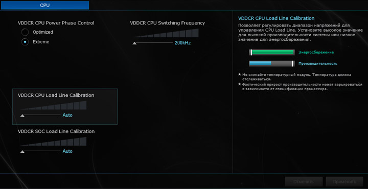
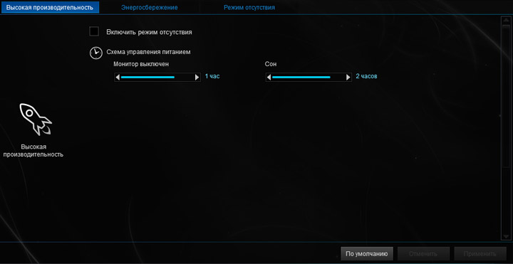
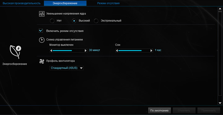
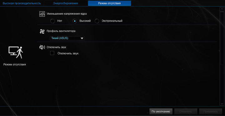
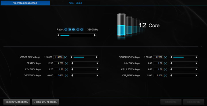
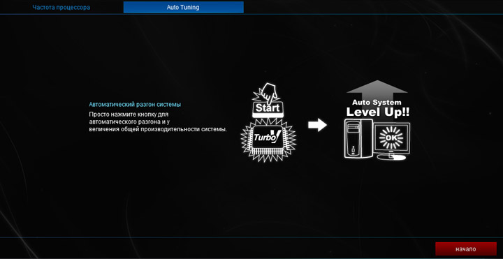
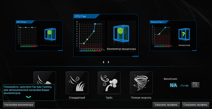
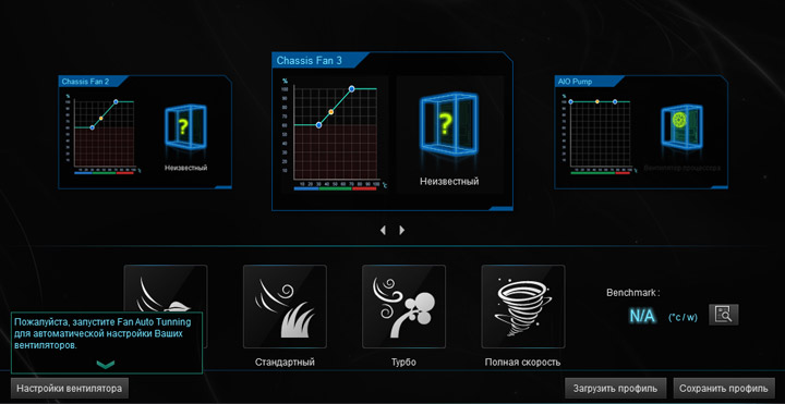
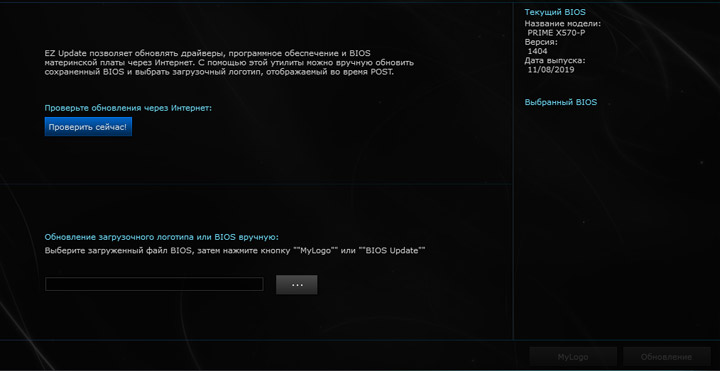
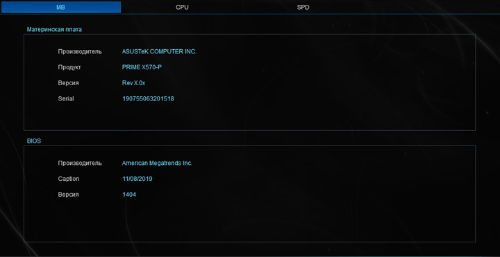
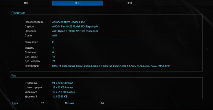
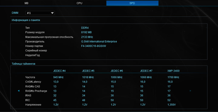
Для работы со звуковой подсистемой предусмотрена фирменная утилита от Realtek. Опять же, функционал самый начальный. Нельзя менять уровень предусиления выходного сигнала, а смена типа оборудования на задней панели, как по мне, никакого эффекта не даёт вообще. Казалось бы, кодек распаяли не самый дешёвый, но на слух говорить про это трудно. Звучание упрощённое, сцена фактически полностью отсутствует, кое-как можно идентифицировать стерео. В диапазоне НЧ инструменты, формально появляясь, буквально пропадают, вокал недостоверен, на ВЧ звуки «песочат», реверберации отсутствуют. Словом, на какие-то положительные, яркие эмоции при прослушивании можно не рассчитывать. Звук есть и для организации условных конференций он подходит, на этом его плюсы заканчиваются. Бонусные утилиты не предусмотрены. Потому «вытянуть» всю картину можно попытаться традиционным эквалайзером, хотя качественно он ничего не изменит, либо же сценарными обработками, с ними на трансформацию с заметным положительным эффектом шансы сильно выше.
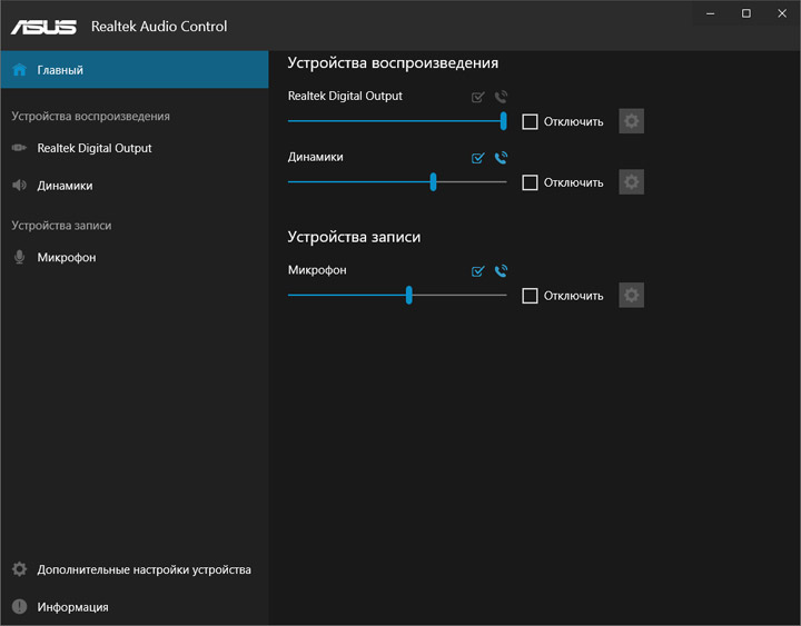
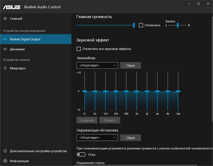
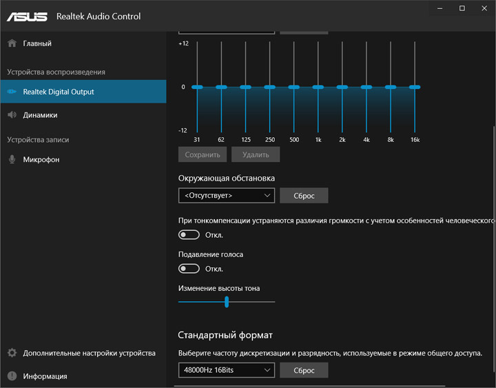
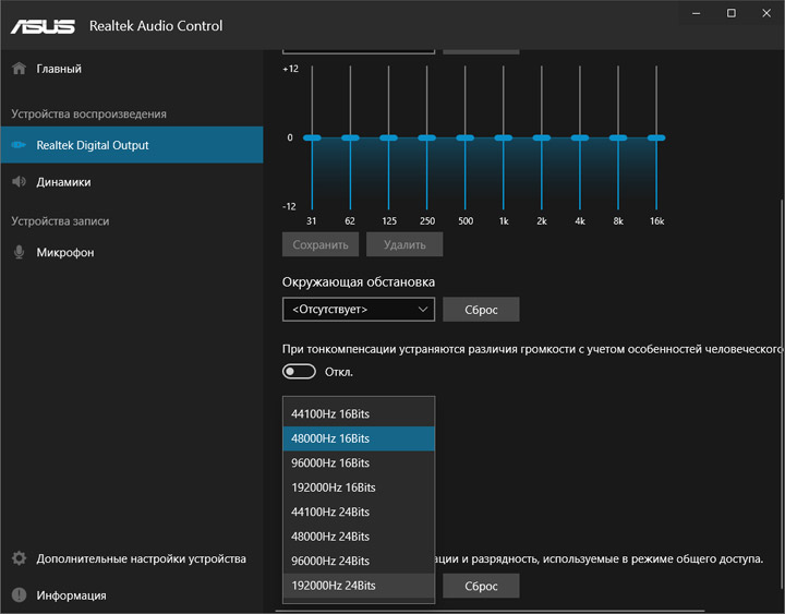
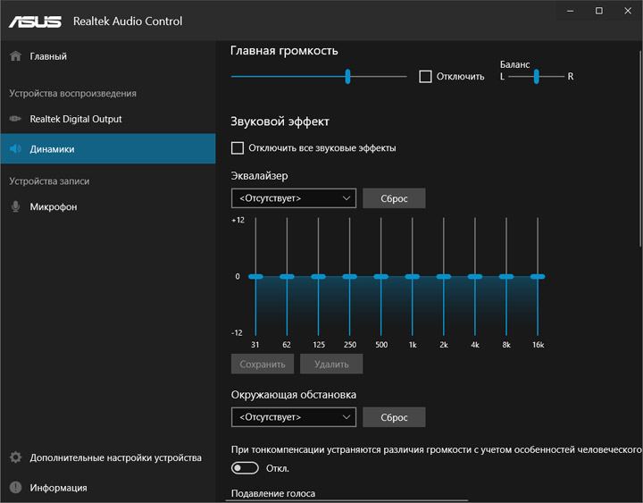
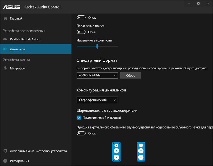
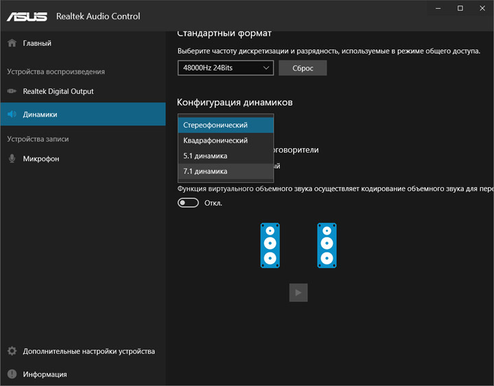
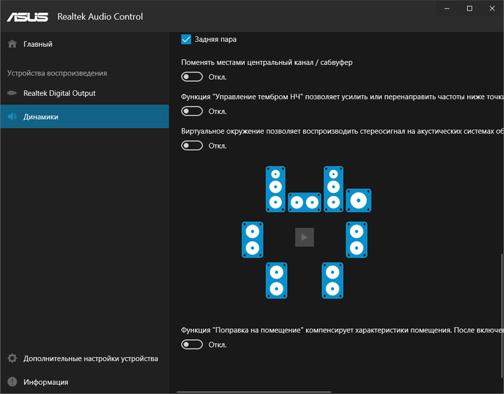
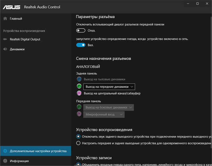
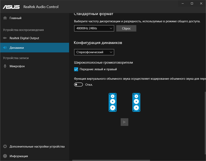
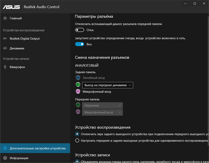
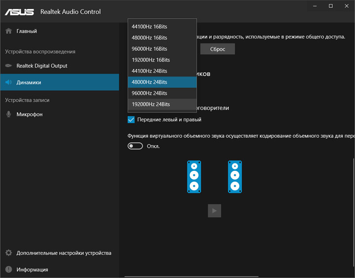
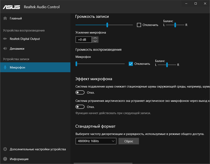
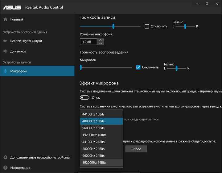
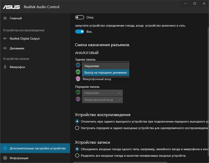
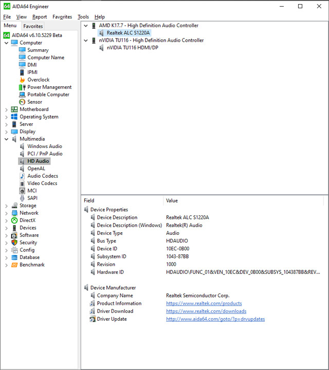
Наблюдение за системными параметрами силами сторонних утилит возможно, но оно не предоставит сведений больше, чем фирменное ПО, проявится лишь температура хаба. Из существенного можно выделить отсутствие деталей о напряжении на модулях памяти.
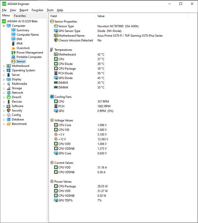
Тестовый стенд
В состав открытого стенда вошли:
- процессор: AMD Ryzen 9 3900X (3,6 ГГц);
- кулер: Noctua NH-U14S;
- термоинтерфейс: Noctua NT-H1;
- память: G.Skill Sniper X F4-3400C16D-16GSXW (2×8 ГБ, 3400 МГц, 16-16-16-36-2T, 1,35 В, Samsung B-die);
- видеокарта: MSI GeForce GTX 1660 Gaming X 6G;
- накопитель: Silicon Power Slim S55 (240 ГБ, SATA 6 Гбит/с, AHCI mode);
- блок питания: SilverStone SST-ST65F-PT (650 Вт) + дополнительный процессорный кабель питания;
- операционная система: Windows 10 Pro x64 (10.0.18362.476), AMD Ryzen Balanced Power Plan, AMD Ryzen Master 2.0.2.1271;
- драйверы: AMD Chipset Drivers 1.09.27.1033, GeForce 441.20.
Разгонный потенциал
Все эксперименты проходили с прошивкой 1404 (AMD AGESA Combo-AM4 1.0.0.4 Patch B). Посмотрим на работу ПК с начальными настройками, частота ОЗУ — 2133 МГц, работу вентилятора на процессоре контролировала плата.
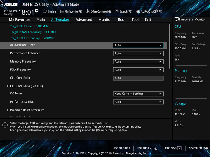
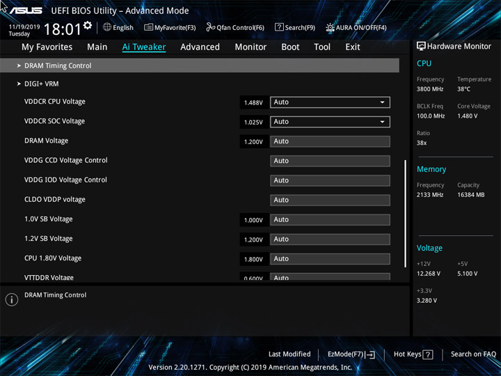


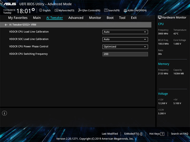
Особенностью поведения ASUS Prime X570-P является меньшая пиковая частота Ryzen 9 3900X в однопоточных сценариях даже в сравнении с не самой выдающейся коллегой по цеху — TUF Gaming X570-Plus. Роста до 4,6 ГГц не происходило ни в один из моментов, даже при замерах ПСП в AIDA64! А вот многопоточные сценарии вышли ожидаемо продуктивными.


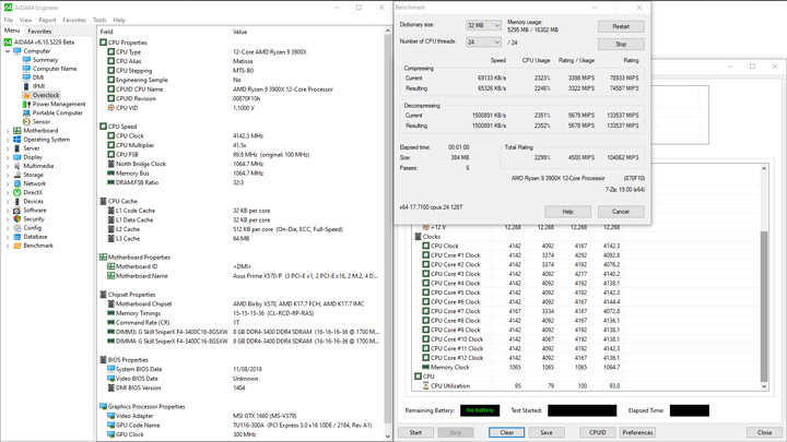

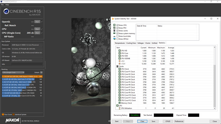


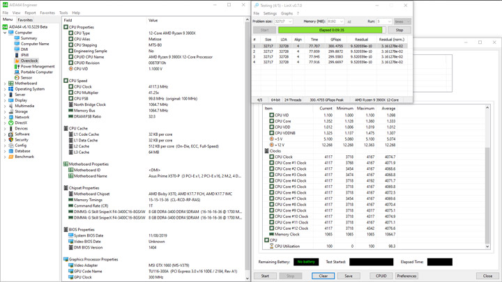


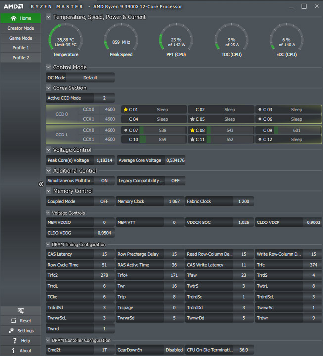


Простой системы характерен уровнем 55 Вт, пиковый при интенсивной нагрузке — 188 Вт.
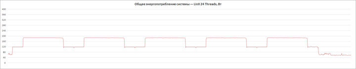
Активация XMP (D.O.C.P.) ускорит память до 3400 МГц, напряжение DRAM увеличится до 1,35 В, SOC Voltage станет равным 1,1 В.
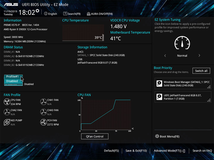
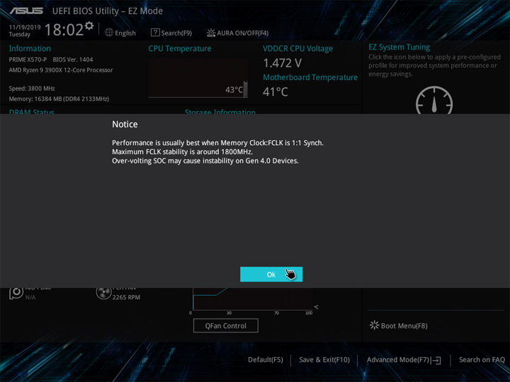
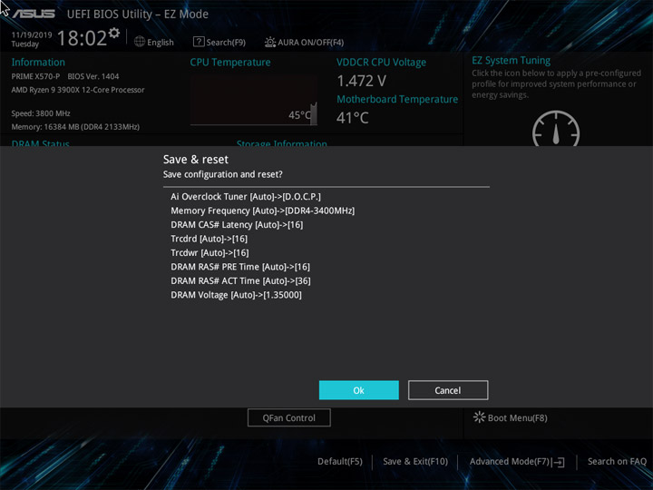
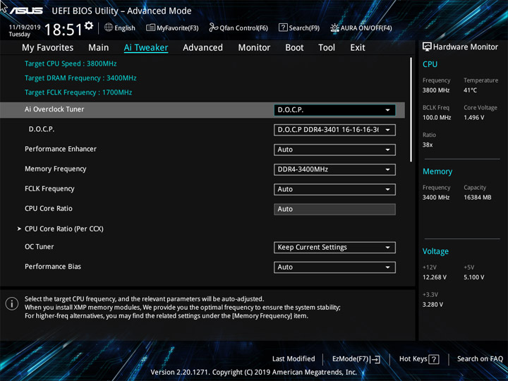
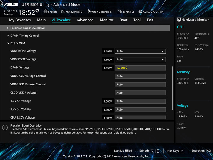
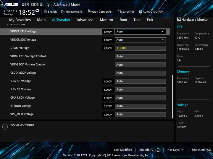


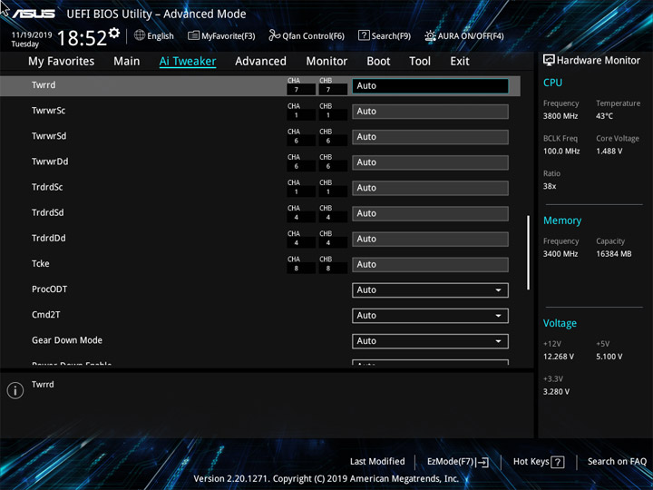

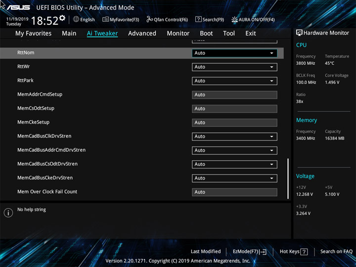

Общая продуктивность системы выросла, но характер поведения остался тем же. Ускорения до 4,6 ГГц не было. Для результатов в LinX обновился наш минимальный результат, пусть отставание от других систем буквально символическое, но оно имеется.


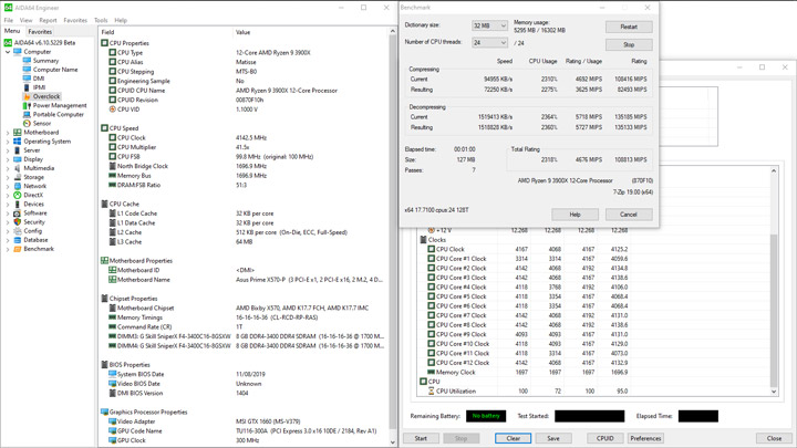


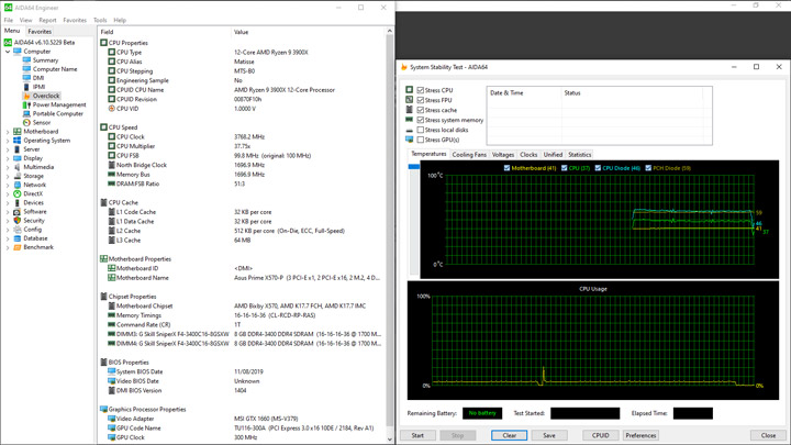


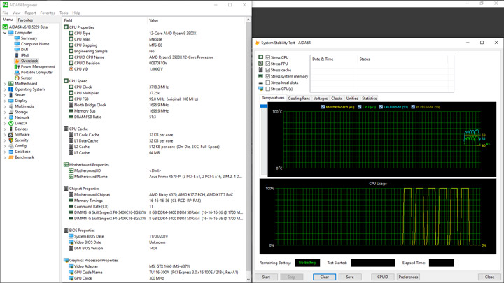
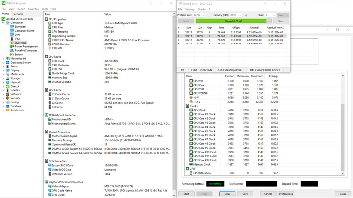
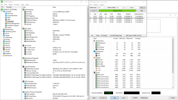


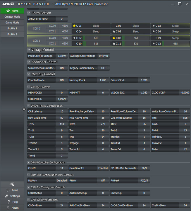
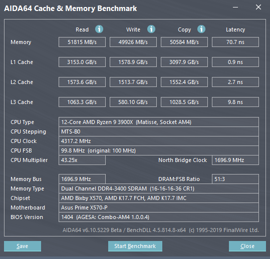
Отсутствие рекордов в производительности позволяет добиться их в энергоэффективности: потребление вышло самым низким для этого участка замеров — 192 Вт в пике, зато в простое цифра также его обновила (62 Вт), что уже не так приятно.
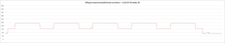
Принцип и очерёдность проведения собственных экспериментов будет совпадать с применённым подходом в обзоре ASUS ROG Crosshair VIII Formula. В отличии от многих прежде протестированных плат, испытуемая не позволила ПК с тестовым набором памяти на частоте 3800 МГц (1:1 с FCLK) попасть на Рабочий стол, потому лишь 3733 МГц стали первым и, к счастью, вполне стабильно функционирующим режимом разгона ОЗУ. Общие настройки задержек и всей подсистемы DRAM, включая напряжение, были идентичны используемым вместе с TUF Gaming X570-Plus. Внимания затребовало напряжение SOC, для его стабилизации форсировался профиль LLC Extreme. Чтобы избежать понижения производительности системы из-за высоких температур ЦП, также деактивировалось управление частотой вращения вентилятора на кулере.
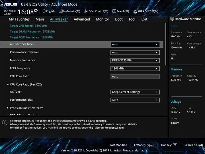
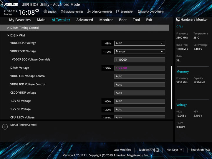
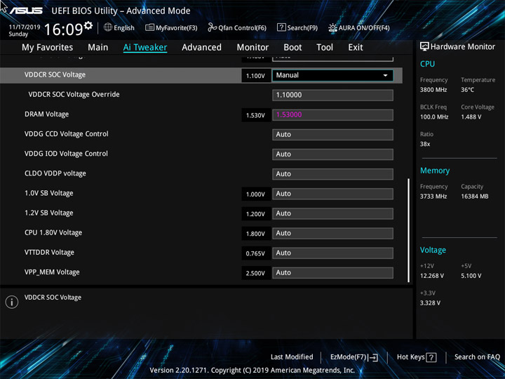


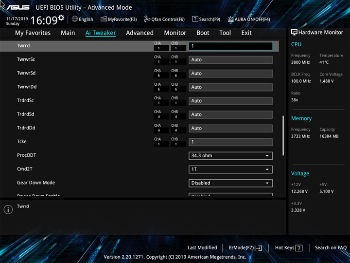
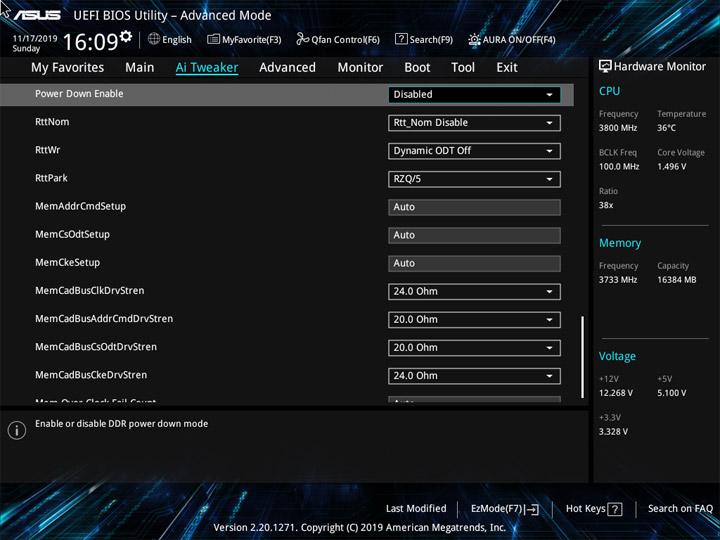
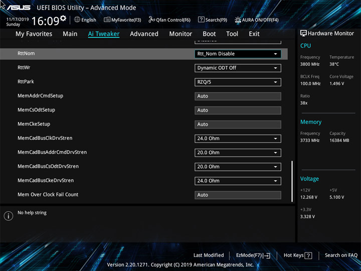
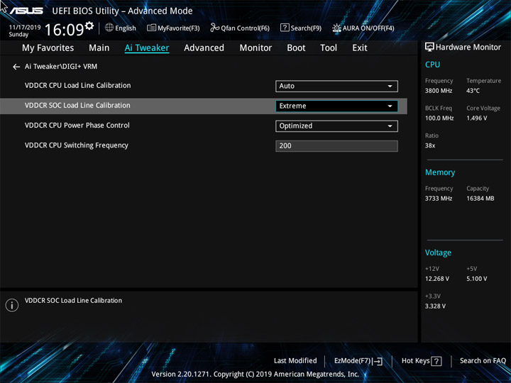
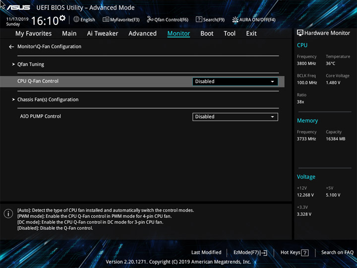
Ввиду сниженной до 23 градусов температуры в помещении дополнительное охлаждение для модулей памяти не потребовалось.
Наконец, вышло зафиксировать рост множителя процессора до x46! Пусть это удалось лишь в тесте Cache & Memory Bechmark. В других однопоточных бенчмарках выдающимся рост частоты называть трудно, ведь итоги выступлений получились минимальными по группе систем, выстроенных на хабе AMD X570. С многопоточной производительностью вновь проблем нет.
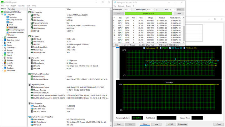
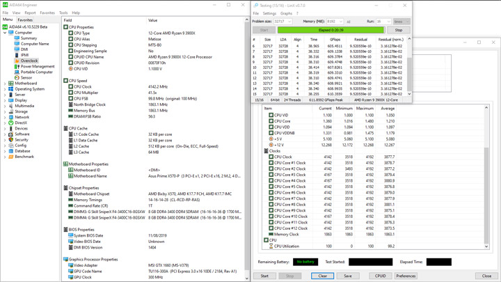
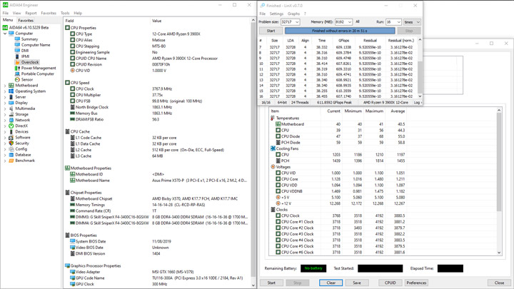
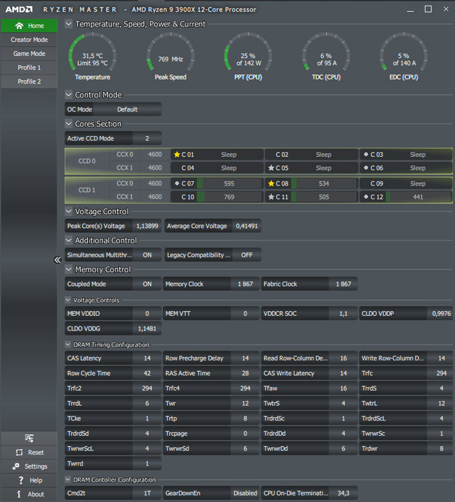


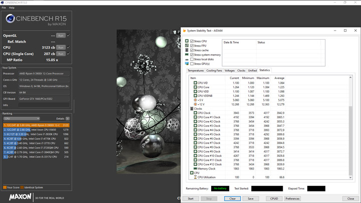


Очередной раз приходится говорить про высокий уровень потребления энергии в простое — 62 Вт, а в пике, если исключить скачок потребления, вызванный активацией режима 3D у видеокарты, он получился рекордно низким (снова) — всего 198 Вт.
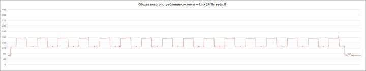
Разобраться в природе вещей помогут эксперименты с фиксируемым напряжением и частотой процессора. Для начала проведём стресс-тест устройства, используя набор из x38.25 и уровня 1,275 В, который фигурирует во всех предыдущих обзорах плат. Для не раз сегодня упомянутого оппонента в лице TUF Gaming X570-Plus нужно было форсировать 1,2875 В, а здесь пришлось взобраться до 1,30625 В и это с максимальным профилем LLC — Extreme. Лишь такая связка удерживала напряжение на задуманной отметке в моменты интенсивных нагрузок с привлечением LLC. Также для стабилизации сборки на один пункт вверх потребовалось увеличить SOC и DRAM Vоltage. Эксперименты с задающей ШИМ-частотой положительного эффекта для стабилизации не выявили, потому она оставалось штатной (200 кГц).
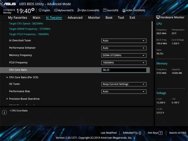


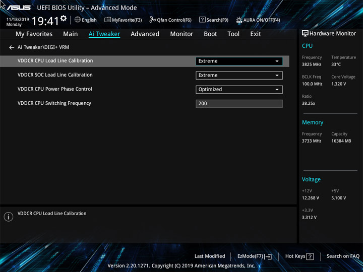
Минимальным напряжение оказалось ровно таким, как и было запланировано — 1,275 В, а в среднем по итогу работы Ryzen 9 3900X в LinX оно равнялось 1,29 В. На фиксированной частоте процессора результаты были даже лучше, чем у ASUS TUF Gaming X570-Plus. А значит до этих пор мы видели один из худших вариантов работы ЦП в автоматическом режиме, без проведения каких-либо его тонких подстроек.
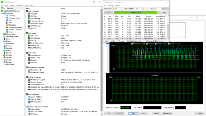
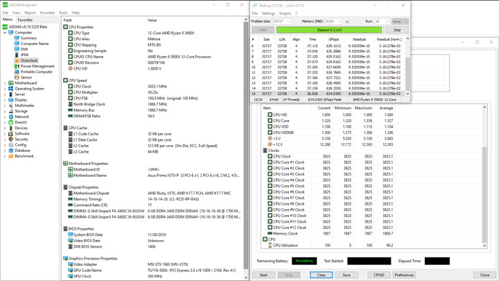
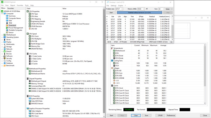


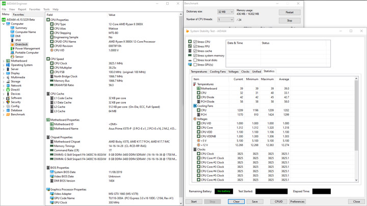


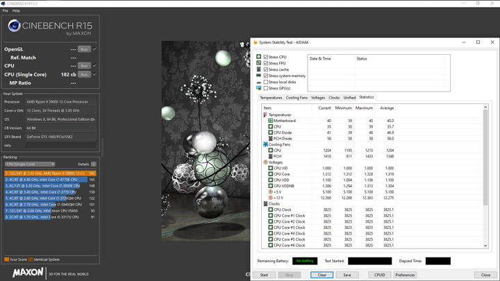


Не принимая во внимание ещё один скачок потребления, уровень уложился между 77 и 320 Вт. Поговорим о температуре VRM. В ходе испытаний температура в помещении держалась у отметок 22–23 градуса. Оказалось, в таком режиме работы больший нагрев испытывает верхняя часть устройства, где предустановлен радиатор меньших размеров. И всё же мне не вышло намерить с тыльной стороны сектора VRM больше, чем 57 градусов! Великолепный результат. Радиаторы прогревались до 42 (больший) и 48 (меньший) градусов, если говорить про замеры их поверхностей сверху.
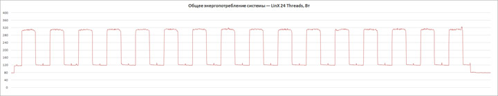
На очереди испытания с привлечением шести прогонов многопоточного бенчмарка в Cinebench R15, при такой нагрузке наш CPU может работать с множителем x43.25. Остаётся подобрать минимальное и необходимое для этого напряжение. Здесь оно равнялось 1,4 В, что опять же чуть больше, чем у неизменного оппонента в ходе нынешних рассуждений.
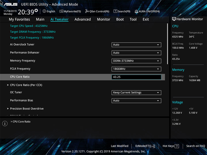
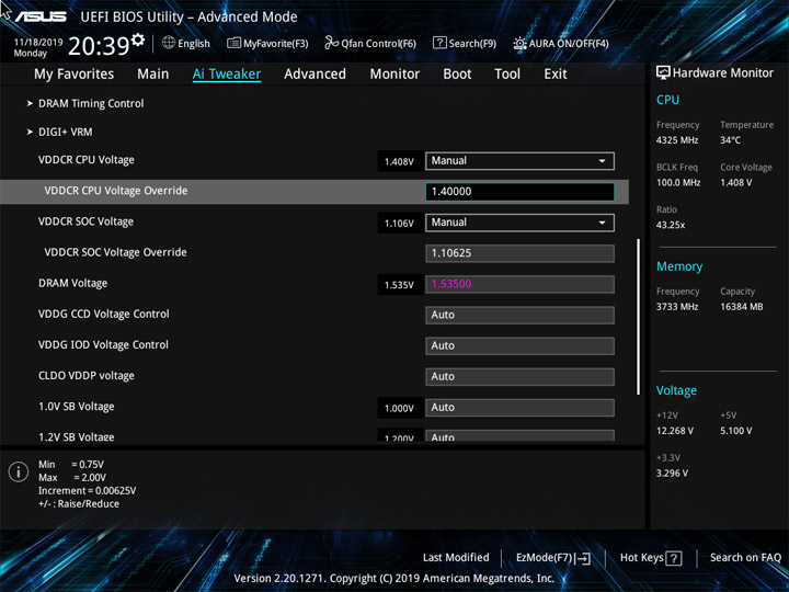
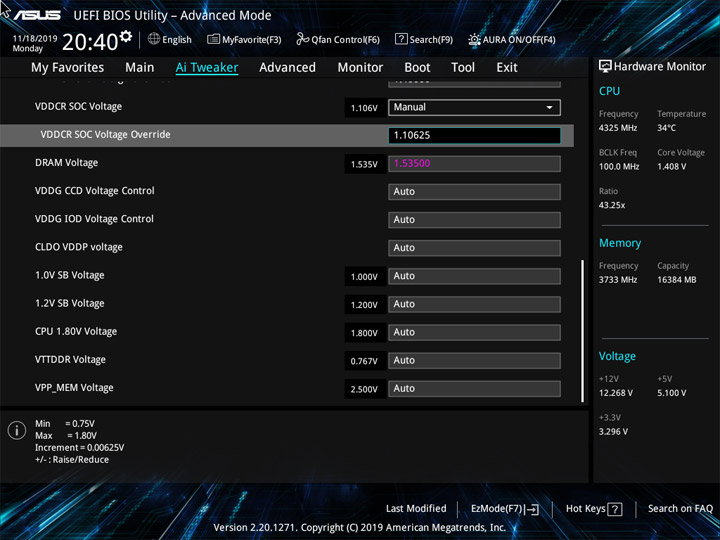

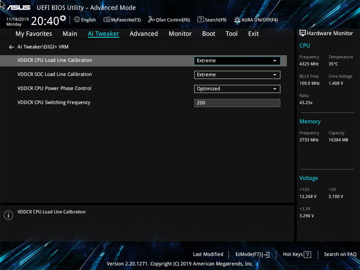
Даже с нагрузкой много проще, чем LinX, напряжение на процессоре (на скриншотах его можно найти как CPU VDDNB) заметно меняется. Впрочем, система по итогу стабильна, а результаты вычислений ожидаемо высокие, в том числе, и для однопоточных сценариев, что вновь подтверждает тезис про невыдающиеся штатные схемы по ускорению процессора.

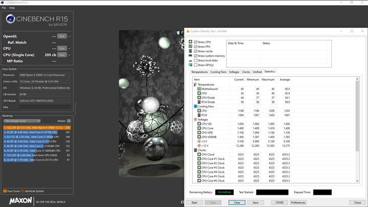

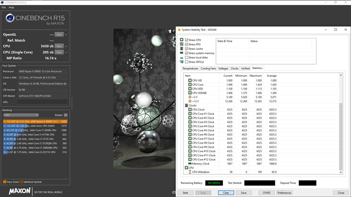

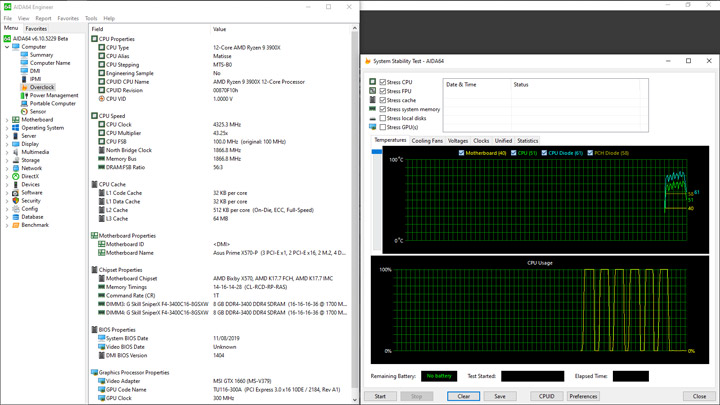

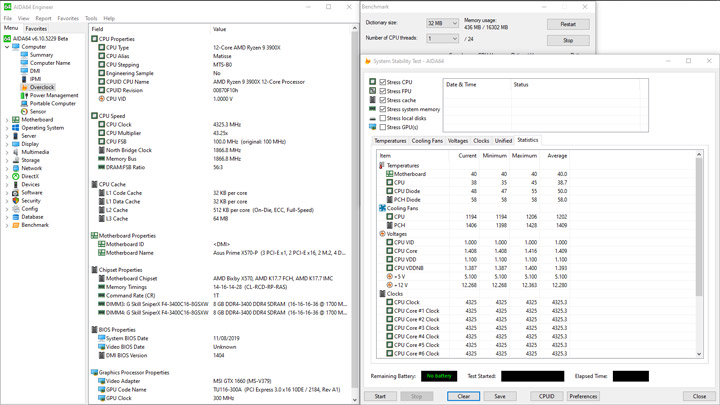
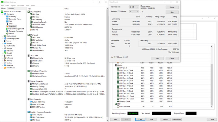


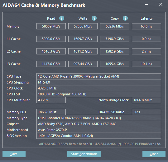
Ещё раз вспомним про недавно рассмотренную модель ASUS TUF Gaming X570-Plus, ведь профиль фирменного разгона ЦП у неё с испытуемой идентичный. Называется он OC Tuner и вся его суть сводится к установке x40 в качестве множителя для Ryzen 9 3900X. Я проводил его форсирование уже после того, как активировался XMP (D.O.C.P.) для ускорения работы ОЗУ. Тем самым, к уже установленным 1,35 и 1,1 вольтам добавился уровень, близкий к 1,3, но уже для процессора.
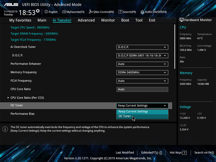
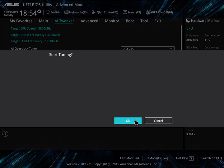
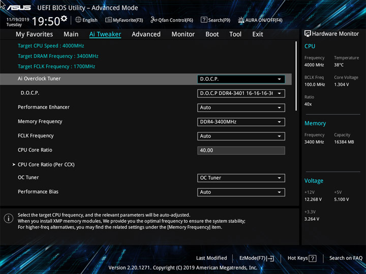
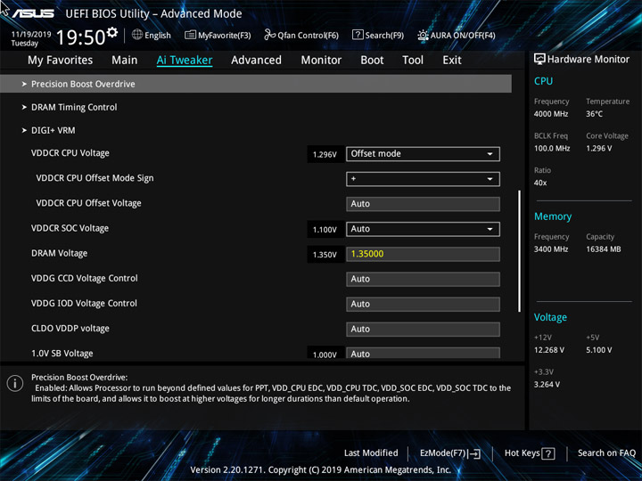
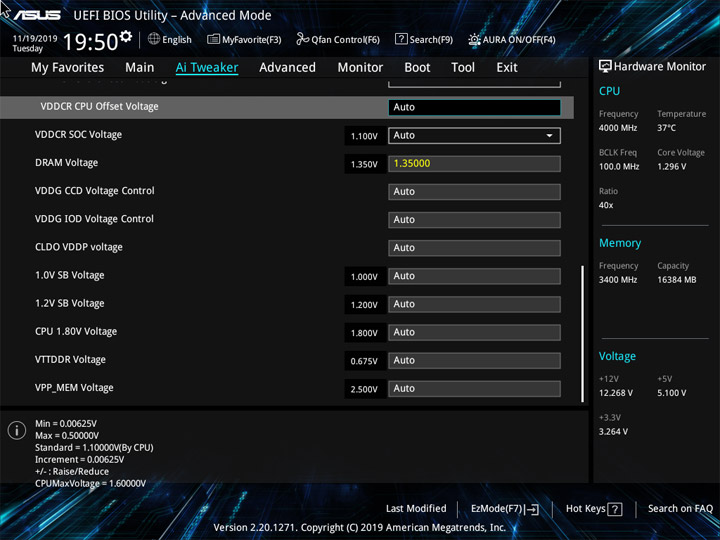
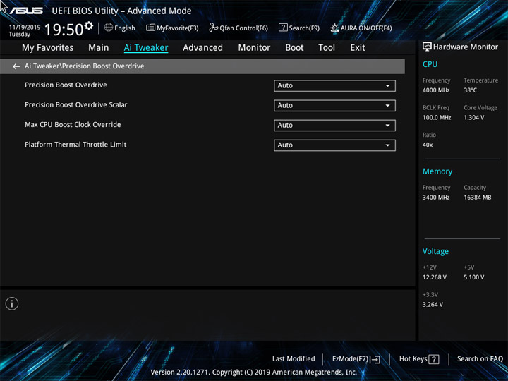
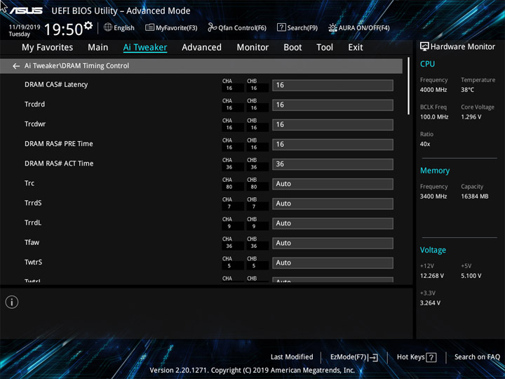
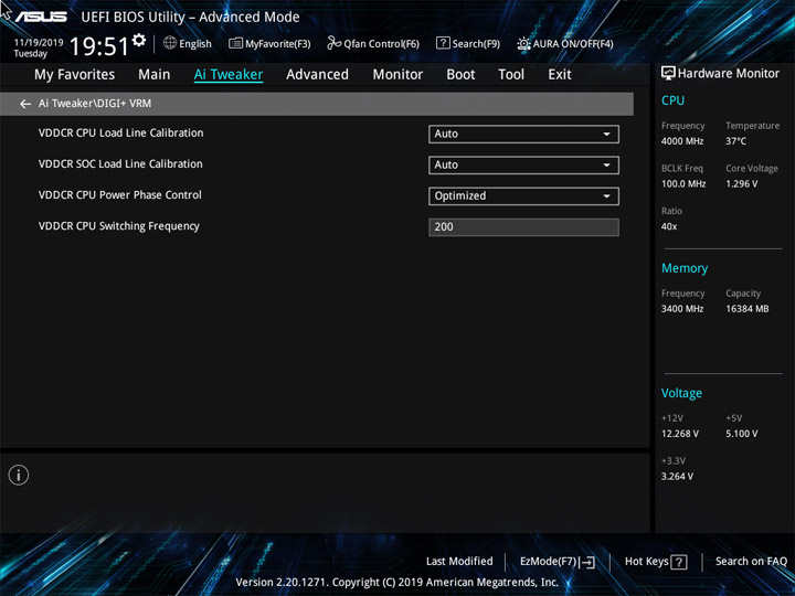
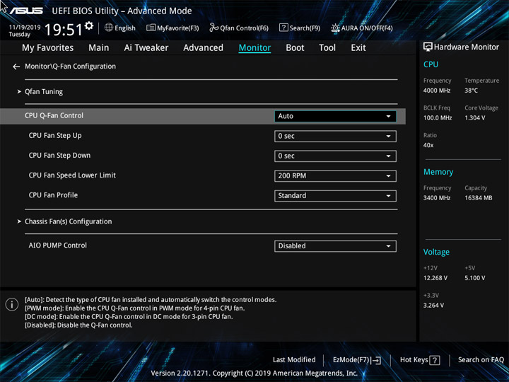
В однопоточном бенчмарке 7-Zip и в LinX отчего-то результат вычислений получился ниже, чем у родственного устройства, вновь, а в остальном разницы нет.


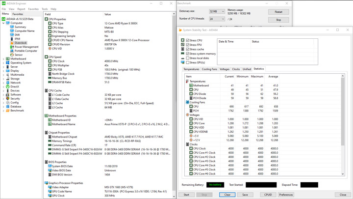
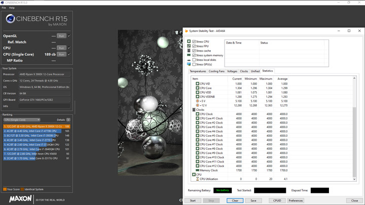

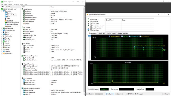

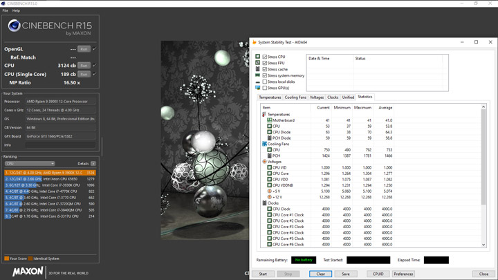

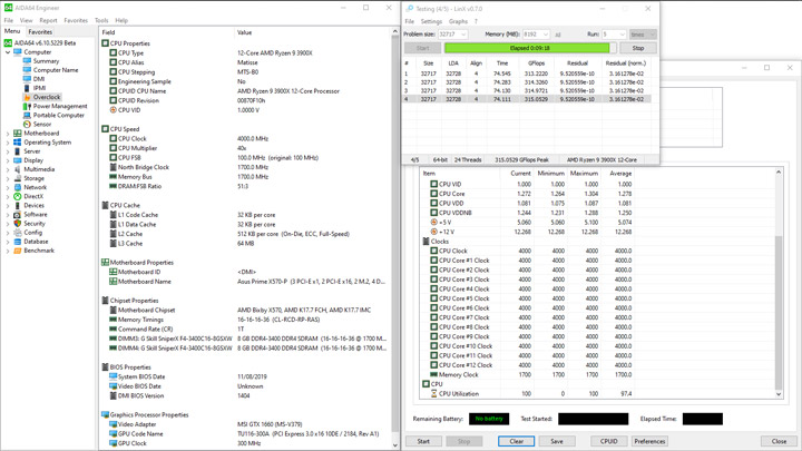

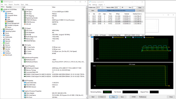
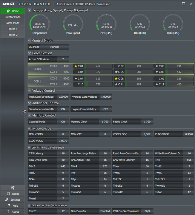
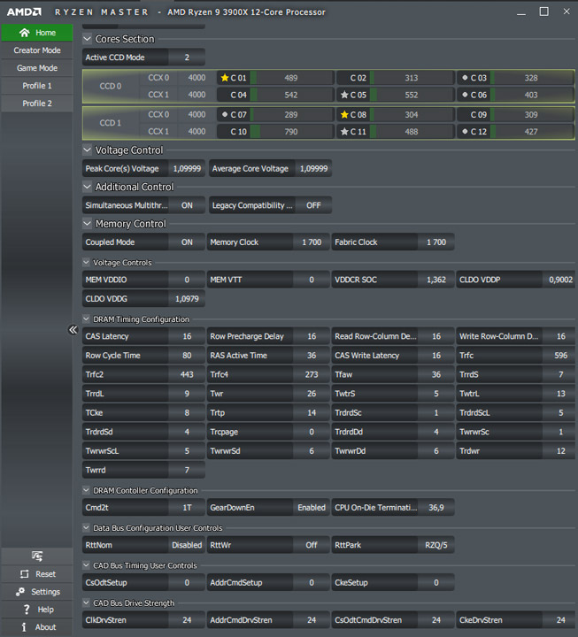

Низкий итоговый балл в LinX можно коррелировать со сниженным потреблением. Уровень в пике составил 188 ватт и снова мало чем «радует» устройство в простое, не опускаясь ниже отметки в 75 Вт.
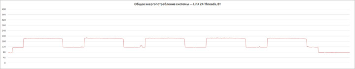
Ввиду общей идеи организации охлаждения хаба X570 здесь и на TUF Gaming X570-Plus, рекомендую почитать про изменение поведения ПК после отключения вентилятора (с целью уменьшения издаваемого шума) в том обзоре. Излагая основную суть — в пассивном режиме работы происходит разогрев чипа до 90 градусов, без какого-либо участия видеокарты, и это в режиме открытого стенда. Словом, без активного охлаждения система работать вряд ли будет и потому любителям бесшумных систем лучше переходить к поиску других устройств.
Вывод
Рассмотренная модель станет замечательным вариантом для сборки мощной системы, предназначенной под изнурительные нагрузки вроде рендеринга тяжёлых сцен, обработки видео и прочих задач, для которых будет приобретён многопоточный процессор уровня Ryzen 9 3900X (или лучше). Преобразователь напряжений в ходе подобных сценариев показывает отличный КПД — потребление энергии оказывается рекордно низким, как и рабочие температуры этого узла. Ускорение оперативной памяти позволяет добиться тех же результатов, что и на более статусных устройствах, то есть нет каких-то упрощений механизмов в UEFI или дизайне, ухудшающих общую отдачу от системы. Поэтому в случае, когда ничего другого от компьютера и не требуется, можно смело приступать к оформлению покупки в любимом магазине.
Но есть и обратная сторона медали. В простое сборка потребляет увеличенное количество энергии, ускорение процессора в однопоточных задачах звезд с неба не хватает. На борту устройства вспомогательные температурные сенсоры отсутствуют, а подключить и использовать собственные возможности нет. В итоге для составления алгоритмов замедления вентиляторов использовать можно лишь два значения — процессора и самой платы (мультиконтроллера). Положение дел на хабе остаётся за кадром, только с привлечением утилит от сторонних производителей можно будет прояснить ситуацию. Вентилятор на плате набирает скорость достаточно быстро и ничего с этим поделать нельзя. Отсутствуют какие-либо готовые профили его работы и тем более ручной режим подстройки. Звуковая подсистема и сетевой адаптер — одни из самых простых на рынке, бонусного ПО для них тоже не предусмотрено. Кроме того, отсутствует площадка типа M.2 для добавочного контроллера беспроводных сетей. Словом, позиционирование вполне чётко указывает на рабочий профиль будущего ПК, достаточно далёкого от сферы развлечений или тихой домашней сборки.
-
Драйверы
13
-
Инструкции по эксплуатации
1
ASUS PRIME X570-P/CSM инструкция по эксплуатации
(196 страниц)
- Языки:Японский
-
Тип:
PDF -
Размер:
10.42 MB -
Описание:
ACC Express User’s Manual ( Japanese Edition )
Просмотр
На NoDevice можно скачать инструкцию по эксплуатации для ASUS PRIME X570-P/CSM. Руководство пользователя необходимо для ознакомления с правилами установки и эксплуатации ASUS PRIME X570-P/CSM. Инструкции по использованию помогут правильно настроить ASUS PRIME X570-P/CSM, исправить ошибки и выявить неполадки.