-
Contents
-
Table of Contents
-
Bookmarks
Quick Links
Related Manuals for Asus P5QL/EPU — Motherboard — ATX
Summary of Contents for Asus P5QL/EPU — Motherboard — ATX
-
Page 1
P5QL/EPU… -
Page 2
Product warranty or service will not be extended if: (1) the product is repaired, modified or altered, unless such repair, modification of alteration is authorized in writing by ASUS; or (2) the serial number of the product is defaced or missing. -
Page 3: Table Of Contents
Special.features…………….1-1 1.3.1 Product highlights …………1-1 1.3.2 ASUS unique features ………… 1-2 1.3.3 ASUS Stylish features …………. 1-3 1.3.4 ASUS Intelligent Overclocking features ……1-3 1.4. Before.you.proceed…………..1-4 1.5. Motherboard.overview…………..1-5 1.5.1 Placement direction …………1-5 1.5.2 Screw holes …………..
-
Page 4
Managing.and.updating.your.BIOS……….2-1 2.1.1 ASUS Update utility …………2-1 2.1.2 Creating a bootable floppy disk ……..2-2 2.1.3 ASUS EZ Flash 2 utility ……….. 2-3 2.1.4 AFUDOS utility …………..2-4 2.1.5 ASUS CrashFree BIOS 3 utility ……..2-5 2.2. BIOS.setup.program…………..2-7 2.2.1… -
Page 5
Boot Device Priority …………2-21 Boot Settings Configuration ………. 2-21 2.7.2 Security …………….. 2-22 2.7.3 2.8. Tools.menu……………… 2-23 2.8.1 ASUS EZ Flash 2 …………2-23 2.8.2 Express Gate …………..2-23 2.8.3 AI NET 2……………. 2-24 2.8.4 ASUS O.C. Profile …………2-24 2.9. -
Page 6: Notices
Notices Federal.Communications.Commission.Statement This device complies with Part 15 of the FCC Rules. Operation is subject to the following two conditions: • This device may not cause harmful interference, and • This device must accept any interference received including interference that may cause undesired operation.
-
Page 7: Safety.information
Safety.information Electrical.safety • To prevent electrical shock hazard, disconnect the power cable from the electrical outlet before relocating the system. • When adding or removing devices to or from the system, ensure that the power cables for the devices are unplugged before the signal cables are connected. If possible, disconnect all power cables from the existing system before you add a device.
-
Page 8
Refer to the following sources for additional information and for product and software updates. ASUS.websites The ASUS website provides updated information on ASUS hardware and software products. Refer to the ASUS contact information. Optional.documentation Your product package may include optional documentation, such as warranty flyers, that may have been added by your dealer. -
Page 9: P5Ql/Epu Specifications Summary
— 4 x 240-pin DIMM sockets support unbuffered non-ECC DDR2 1066/800/667MHz memory modules — Supports up to 16GB system memory * Refer to www.asus.com or this user manual for the Memory QVL (Qualified Vendors Lists) ** Due to the memory address limitation on 32-bit…
-
Page 10
1 x System panel connector BIOS.features 8Mb Flash ROM, AMI BIOS, PnP, DMI 2.0, WfM 2.0, SM BIOS 2.3, ACPI 2.0a, ASUS EZ Flash 2, ASUS CrashFree BIOS 3 Manageability WfM 2.0, DMI 2.0, WOL by PME, WOR by PME, PXE… -
Page 11: Chapter.1.Product.introduction
Green.ASUS. This motherboard and its packaging comply with the European Union’s Restriction on the use of Hazardous Substances (RoHS). This is in line with the ASUS vision of creating environment-friendly and recyclable products/packaging to safeguard consumers’ health while minimizing the impact on the environment.
-
Page 12: Asus Unique Features
What’s more, the user-friendly picture manager lets you view your pictures without entering Windows at anytime! • The actual boot time depends on the system configuration. • ASUS Express Gate supports file uploading from SATA HDDs, ODDs and USB drives and downloading to USB drives only. ASUS.Power.Saving.Solution.
-
Page 13: Asus Stylish Features
System power saving by detecting current PC loadings and intelligently moderating power in real-time. Smart power saving without interrupting your work. ASUS.EZ.DIY. ASUS EZ DIY feature collection provides you with easy ways to install computer components, update the BIOS or back up your favorite settings. ASUS O.C. Profile The motherboard features the ASUS O.C.
-
Page 14: Before.you.proceed
1.4. Before.you.proceed Take note of the following precautions before you install motherboard components or change any motherboard settings. • Unplug the power cord from the wall socket before touching any component. • Use a grounded wrist strap or touch a safely grounded object or a metal object, such as the power supply case, before handling components to avoid damaging them due to static electricity.
-
Page 15: Motherboard.overview
The edge with external ports goes to the rear part of the chassis as indicated in the image below. 1.5.2. Screw.holes Place six screws into the holes indicated by circles to secure the motherboard to the chassis. Do not overtighten the screws! Doing so can damage the motherboard. Place.this.side.towards. the.rear.of.the.chassis P5QL/EPU ASUS P5QL/EPU…
-
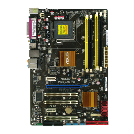
Page 16: Motherboard Layout
1.5.3. Motherboard.layout 20.3cm(8.0in) PWR_FAN KBMS ATX12V SPDIF_O LGA775 USB34 CHA_FAN LAN1_USB12 Intel ® AUDIO Realtek PCIEX1_1 8111C P5QL/EPU PCIEX16 SATA1 PCI1 SATA2 SATA3 SATA4 Intel ® SATA5 ICH10 SATA6 PCI2 Lithium Cell CLRTC PCIEX1_2 CMOS Power BIOS CHASSIS PANEL VT1708S PCI3 SB_PWR PRI_IDE…
-
Page 17: Layout Contents
Contact your retailer immediately if the PnP cap is missing, or if you see any damage to the PnP cap/socket contacts/motherboard components. ASUS will shoulder the cost of repair only if the damage is shipment/ transit-related.
-
Page 18: Installing The Cpu
1.6.1. Installing.the.CPU To install a CPU: Locate the CPU socket on the motherboard. P5QL/EPU P5QL/EPU CPU socket 775 Before installing the CPU, ensure that the socket box is facing towards you and the load lever is on your left. Press the load lever with your thumb Retention.tab (A), then move it to the left (B) until it is released from the retention tab.
-
Page 19
(B) until it snaps into the retention tab. The motherboard supports Intel ® LGA775 processors with the Intel Enhanced Intel SpeedStep ® ® Technology (EIST) and Hyper- Threading Technology. Refer to the Appendix for more information on these CPU features. ASUS P5QL/EPU… -
Page 20: Installing The Cpu Heatsink And Fan
1.6.2. Installing.the.CPU.heatsink.and.fan The Intel LGA775 processor requires a specially designed heatsink and fan assembly to ® ensure optimum thermal condition and performance. • When you buy a boxed Intel processor, the package includes the CPU fan and ® heatsink assembly. If you buy a CPU separately, ensure that you use only Intel -certified ®…
-
Page 21: Uninstalling The Cpu Heatsink And Fan
The motherboard comes with four Double Data Rate 2 (DDR2) Dual Inline Memory Modules (DIMM) sockets. The figure illustrates the location of the DDR2 DIMM sockets: P5QL/EPU P5QL/EPU 240-pin DDR2 DIMM sockets Channel Sockets Channel A DIMM_A1 and DIMM_A2 Channel B DIMM_B1 and DIMM_B2 ASUS P5QL/EPU 1-11…
-
Page 22: Memory Configurations
1.7.2 Memory configurations You may install 512MB, 1GB, 2GB, and 4GB unbuffered non-ECC DDR2 DIMMs into the DIMM sockets. Recommended Memory Configurations Sockets Mode DIMM_A1 DIMM_A2 DIMM_B1 DIMM_B2 Populated Single-Channel Populated Dual-channel.(1) Populated Populated Dual-channel.(2) Populated Populated Populated Populated • When using only one DDR2 DIMM, start installing it from DIMM_A1 or DIMM_B1 for better overclocking capability.
-
Page 23
• • • Kingmax KLDD48F-A8K15 Kingmax KKA8FFIXF-HFS-25A • • • 512MB Apacer 78.91G91.9K5 Apacer AM4B5708JQJS8E0751C • • • Apacer 78.01GA0.9K5 Apacer AM4B5808CQJS8E0749D • • • Apacer 78.A1GA0.9K4 Apacer AM4B5808CQJS8E0747D • • • (continued on the next page) ASUS P5QL/EPU 1-13… -
Page 24
DDR2-800MHz.capability DIMM.support Size Vendor Part.No. Chip.Brand Chip.No. 512MB Transcend TS128MLQ64V8J512MB Micron 7HD22 D9GMH • • • 512MB Transcend TS64MLQ64V8J512MB Transcend Heat-Sink Package • • • 512MB ADATA M2OAD6G3H3160Q1E58 ADATA AD29608A8A-25EG80812 • • • 512MB VDATA M2GVD6G3H3160Q1E52 VDATA VD29608A8A-25EG20813 • • •… -
Page 25
•. B*: Supports one pair of modules inserted into either the yellow slots or the black slots as one pair of Dual-channel memory configuration. •. C*: Supports four modules inserted into both the yellow slots and the black slots as two pairs of Dual-channel memory configuration. ASUS P5QL/EPU 1-15… -
Page 26: Installing A Dimm
1.7.3. Installing.a.DIMM Unplug the power supply before adding or removing DIMMs or other system components. Failure to do so can cause severe damage to both the motherboard and the components. Unlock a DDR2 DIMM DDR2.DIMM.notch socket by pressing the retaining clips outward.
-
Page 27: Expansion.slots
This motherboard supports PCI Express x1 network cards, SCSI cards and other cards that comply with the PCI Express specifications. 1.8.6. PCI.Express.x16.slot This motherboard supports a PCI Express x16 graphics card that complies with the PCI Express specifications. ASUS P5QL/EPU 1-17…
-
Page 28: Jumper
1.9. Jumper Clear.RTC.RAM.(3-pin.CLRTC) This jumper allows you to clear the Real Time Clock (RTC) RAM in CMOS. You can clear the CMOS memory of date, time, and system setup parameters by erasing the CMOS RTC RAM data. The onboard button cell battery powers the RAM data in CMOS, which include system setup information such as system passwords.
-
Page 29: Connectors
Microphone.port.(pink). This port connects a microphone. Side.Speaker.Out.port.(gray). This port connects the side speakers in an 8-channel audio configuration. Refer to the audio configuration table on the next page for the function of the audio ports in 2, 4, 6, or 8-channel configuration. ASUS P5QL/EPU 1-19…
-
Page 30: Internal Connectors
Audio 2, 4, 6, or 8-channel configuration Headset. Port 4-channel 6-channel 8-channel 2-channel Light Blue Line In Line In Line In Line In Lime Line Out Front Speaker Out Front Speaker Out Front Speaker Out Pink Mic In Mic In Mic In Mic In Orange…
-
Page 31
• Use the 80-conductor IDE cable for Ultra DMA 133/100/66 IDE devices. If any device jumper is set as “Cable-Select,” make sure all other device jumpers have the same setting. PRI_IDE P5QL/EPU PIN1 NOTE:Orient the red markings on the IDE ribbon cable to PIN 1. P5QL/EPU IDE connector ASUS P5QL/EPU 1-21… -
Page 32
PWR_FAN +12V Rotation CPU_FAN CPU FAN PWR CPU FAN IN CPU FAN PWM CHA_FAN P5QL/EPU +12V Rotation P5QL/EPU fan connectors Only the CPU fan supports the ASUS Q-FAN feature. 1-22 Chapter 1: Product introduction… -
Page 33
The USB module cable is purchased separately. Optical.drive.audio.connector.(4-pin.CD) These connectors allow you to receive stereo audio input from sound sources such as a CD-ROM, TV tuner, or MPEG card. Right Audio Channel Left Audio Channel P5QL/EPU P5QL/EPU Internal audio connector ASUS P5QL/EPU 1-23… -
Page 34: Chassis Intrusion Connector
Front.panel.audio.connector.(10-1.pin.AAFP) This connector is for a chassis-mounted front panel audio I/O module that supports either HD Audio or legacy AC`97 audio standard. Connect one end of the front panel audio I/O module cable to this connector. AAFP PIN 1 PIN 1 P5QL/EPU HD-audio-compliant Legacy AC’97…
-
Page 35
• Do not forget to connect the 4-pin EATX12V power plug; otherwise, the system will not boot. • Use of a PSU with a higher power output is recommended when configuring a system with more power-consuming devices. The system may become unstable or may not boot up if the power is inadequate. ASUS P5QL/EPU 1-25… -
Page 36: System.panel.connector
11.. System.panel.connector.(20-8.pin.PANEL) This connector supports several chassis-mounted functions. PLED SPEAKER PANEL PIN 1 P5QL/EPU IDE_LED PWRSW RESET * Requires an ATX power supply P5QL/EPU System panel connector •. System.power.LED.(2-pin.PLED) This 2-pin connector is for the system power LED. Connect the chassis power LED cable to this connector.
-
Page 37: Software.support
The following screen is used for reference only. Click.an.icon.to. display.Support.DVD/ motherboard.information Click.an.item.to.install If Autorun is NOT enabled in your computer, browse the contents of the Support DVD to locate the file ASSETUP.EXE from the BIN folder. Double-click the ASSETUP.EXE to run the DVD. ASUS P5QL/EPU 1-27…
-
Page 38
1-28 Chapter 1: Product introduction… -
Page 39: Chapter.2.Bios.information
BIOS in the future. Copy the original motherboard BIOS using the ASUS Update or AFUDOS utilities. 2.1.1. ASUS.Update.utility The ASUS Update is a utility that allows you to manage, save, and update the motherboard BIOS in Windows environment. The ASUS Update utility allows you to: ®…
-
Page 40: Creating A Bootable Floppy Disk
Programs.>.ASUS.>.ASUSUpdate.>.ASUSUpdate. Select Update.BIOS from.the.Internet from the drop-down menu, then click Next. Select the ASUS FTP site nearest you to avoid network traffic, or click Auto.Select then click Next. From the FTP site, select the BIOS version that you wish to download then click Next.
-
Page 41: Asus Ez Flash 2 Utility
2.1.3. ASUS.EZ.Flash.2.utility The ASUS EZ Flash 2 feature allows you to update the BIOS without having to go through the long process of booting from a floppy disk and using a DOS-based utility. The EZ Flash 2 utility is built-in the BIOS chip so it is accessible by pressing <Alt>.+.<F2> during the Power- On Self Tests (POST).
-
Page 42: Afudos Utility
Updating the BIOS file To update the BIOS file using the AFUDOS utility: Visit the ASUS website (www.asus.com) and download the latest BIOS file for the motherboard. Save the BIOS file to a bootable floppy disk. We recommend that you write the BIOS filename on a piece of paper; you will need to key in the exact BIOS filename at the DOS prompt later.
-
Page 43: Asus Crashfree Bios 3 Utility
2.1.5. ASUS.CrashFree.BIOS.3.utility The ASUS CrashFree BIOS 3 is an auto recovery tool that allows you to restore the BIOS file when it fails or gets corrupted during the updating process. You can update a corrupted BIOS file using the motherboard support DVD, a floppy disk or a USB flash disk that contains the updated BIOS file.
-
Page 44
BIOS file and starts flashing the corrupted BIOS file. Restart the system after the utility completes the updating process. • Only the USB flash disk with FAT 32/16 format and single partition can support ASUS CrashFree BIOS 3. The device size should be smaller than 8GB. -
Page 45: Bios.setup.program
• The BIOS setup screens shown in this section are for reference purposes only, and may not exactly match what you see on your screen. • Visit the ASUS website at www.asus.com to download the latest BIOS file for this motherboard.
-
Page 46: Bios Menu Screen
2.2.1. BIOS.menu.screen Menu.items Menu.bar Configuration fields General.help BIOS SETUP UTILITY Main Ai Tweaker Advanced Power Boot Tools Exit Use [ENTER], [TAB] or System Time [14:14:35] [SHIFT-TAB] to select System Date [Wed 04/16/2008] a field. Legacy Diskette A [1.44M, 3.5 in.] Use [+] or [-] to configure system Time.
-
Page 47: Menu Items
Press the Pop-up.window <Up>./.<Down> arrow keys or Scroll.bar <Page.Up>./<Page.Down> keys to display the other items on the screen. 2.2.9. General.help At the top right corner of the menu screen is a brief description of the selected item. ASUS P5QL/EPU…
-
Page 48: Main.menu
2.3. Main.menu When you enter the BIOS Setup program, the Main menu screen appears, giving you an overview of the basic system information. Refer to section 2.2.1.BIOS.menu.screen for information on the menu screen items and how to navigate through them. BIOS SETUP UTILITY Main Ai Tweaker…
-
Page 49: Storage Configuration
Selects the time out value for detecting ATA/ATAPI devices. Configuration options: [0] [5] [10] [15] [20] [25] [30] [35] 2.3.6. System.Information This menu gives you an overview of the general system specifications. The BIOS automatically detects the items in this menu. ASUS P5QL/EPU 2-11…
-
Page 50: Ai.tweaker.menu
Bios.Information Displays the auto-detected BIOS information. Processor Displays the auto-detected CPU specification. System.Memory Displays the auto-detected system memory. 2.4. Ai.Tweaker.menu The Ai.Tweaker menu items allow you to configure system performance settings. Select an item then press <Enter> to display the configuration options. Take caution when changing the settings of the Ai Tweaker menu items.
-
Page 51
Allows you to set the SB voltage. Configuration options: [1.5V] [1.6V] CPU.Vcore.offset.[Auto] Allows you to set the CPU vcore offset. Configuration options: [Auto] [0mv] [50mv] [100mv] [150mv] Phase.Operating.Control.[Auto] Allows you to enable or disable the EPU function. Configuration options: [Auto] [Fix EPU] ASUS P5QL/EPU 2-13… -
Page 52: Advanced.menu
2.5. Advanced.menu The Advanced menu items allow you to change the settings for the CPU and other system devices. Take caution when changing the settings of the Advanced menu items. Incorrect field values can cause the system to malfunction. BIOS SETUP UTILITY Main Ai Tweaker Advanced…
-
Page 53: Chipset
DRAM RAS# Precharge [5 DRAM Clocks] Configuration options: [3 DRAM Clocks] [4 DRAM Clocks] ~ [18 DRAM Clocks]. RAS# Activate to Precharge [15 DRAM Clocks] Configuration options: [3 DRAM Clocks] [4 DRAM Clocks] ~ [34 DRAM Clocks]. ASUS P5QL/EPU 2-15…
-
Page 54: Onboard Devices Configuration
RAS# to RAS# Delay [Auto] Controls the latency between the DDR SDRAM active command and the read/write command. Configuration options: [Auto] [1 DRAM Clocks] [2 DRAM Clocks] [3 DRAM Clocks] ~ [15 DRAM Clocks]. Row Refresh Cycle Time [Auto] Configuration options: [Auto] [20 DRAM Clocks] [25 DRAM Clocks] [30 DRAM Clocks] [35 DRAM Clocks] [40 DRAM Clocks] [45 DRAM Clocks] [50 DRAM Clocks] [55 DRAM Clocks] [60 DRAM Clocks] [65 DRAM Clocks] [70 DRAM Clocks] [80 DRAM Clocks] [85 DRAM Clocks] [105 DRAM Clocks] [132 DRAM Clocks]…
-
Page 55: Usb Configuration
When set to [No], BIOS configures all the devices in the system. When set to [Yes] and if you install a Plug and Play operating system, the operating system configures the Plug and Play devices not required for boot.Configuration options: [No] [Yes] ASUS P5QL/EPU 2-17…
-
Page 56: Power.menu
2.6. Power.menu The Power menu items allow you to change the settings for the Advanced Power Management (APM). Select an item then press <Enter> to display the configuration options. BIOS SETUP UTILITY Main Ai Tweaker Advanced Power Boot Tools Exit Select the ACPI state Suspend Mode [Auto]…
-
Page 57: Apm Configuration
This feature requires an ATX power supply that provides at least 1A on the +5VSB lead. Configuration options: [Disabled] [Enabled] 2.6.5. Hardware.Monitor CPU.Temperature.[xxxºC/xxxºF].. MB.Temperature.[xxxºC/xxxºF]. The onboard hardware monitor automatically detects and displays the motherboard and CPU temperatures. Select [Ignored] if you do not wish to display the detected temperatures. ASUS P5QL/EPU 2-19…
-
Page 58
CPU.Fan.Speed.[xxxxRPM].or.[Ignored] The onboard hardware monitor automatically detects and displays the CPU fan speed in rotations per minute (RPM). If the fan is not connected to the motherboard, the field shows N/A. CPU.Q-Fan.Control.[Disabled] Allows you to enable or disable the CPU Q-Fan controller. Configuration options: [Disabled] [Enabled] Chassis.Fan.Speed.[xxxxRPM].or.[Ignored]./.[N/A] The onboard hardware monitor automatically detects and displays the chassis fan speed in… -
Page 59: Boot.menu
POST items. Configuration options: [Disabled] [Enabled] Full.Screen.Logo.[Enabled] This allows you to enable or disable the full screen logo display feature. Configuration options: [Disabled] [Enabled] Set this item to [Enabled] to use the ASUS MyLogo2 feature. ™ AddOn.ROM.Display.Mode.[Force.BIOS] Sets the display mode for option ROM. Configuration options: [Force BIOS] [Keep Current] Bootup.Num-Lock.[On]…
-
Page 60: Security
2.7.3. Security The Security menu items allow you to change the system security settings. Select an item then press <Enter> to display the configuration options. Change.Supervisor.Password Select this item to set or change the supervisor password. The Supervisor.Password item on top of the screen shows the default Not.Installed. After you set a password, this item shows Installed.
-
Page 61: Tools.menu
2.8.1. ASUS.EZ.Flash.2 Allows you to run ASUS EZ Flash 2. When you press <Enter>, a confirmation message appears. Use the left/right arrow key to select between [Yes] or [No], then press <Enter> to confirm your choice. Please see section 2.1.3 for details.
-
Page 62: Ai Net 2
Enables or disables checking of the Realtek LAN cable during the Power-On Self-Test (POST). Configuration options: [Disabled] [Enabled] 2.8.4 ASUS O.C. Profile Save to Profle 1/2 Allows you to save the current BIOS file to the BIOS Flash. Press <Enter> to save the file.
-
Page 63
This option allows you to load the default values for each of the parameters on the Setup menus. When you select this option or if you press <F5>, a confirmation window appears. Select OK to load default values. Select Exit.&.Save.Changes or make other changes before saving the values to the non-volatile RAM. ASUS P5QL/EPU 2-25… -
Page 64
2-26 Chapter 2: BIOS setup…
P5QL/EPU

Регистрация устройства поможет вам управлять его гарантией, получать техническую поддержку и отслеживать статус ремонта.
Регистрация продукта
Руководства пользователя
Версия F4277
2.1 MB
P5QL/EPU user’s manual (French)
Версия G4277
2.57 MB
P5QL/EPU user’s manual (German)
Версия T4204
1.97 MB
Motherboard Installation Guide (Traditional Chinese)
Версия C4204
1.83 MB
Motherboard Installation Guide (Simplified Chinese)
Версия A4277
4.1 MB
P5QL/EPU Asian Quick Start Guide for Multiple Languages
Версия E4277
2.22 MB
P5QL/EPU user’s manual(English)
E4277
First Edition V1
December 2008
Copyright © 2008 ASUSTeK Computer, Inc. All Rights Reserved.
No part of this manual, including the products and software described in it, may be reproduced,
transmitted, transcribed, stored in a retrieval system, or translated into any language in any form or by any
means, except documentation kept by the purchaser for backup purposes, without the express written
permission of ASUSTeK Computer Inc. («ASUS»).
Product warranty or service will not be extended if: (1) the product is repaired, modified or altered, unless
such repair, modification of alteration is authorized in writing by ASUS; or (2) the serial number of the
product is defaced or missing.
ASUS PROVIDES THIS MANUAL «AS IS» WITHOUT WARRANTY OF ANY KIND, EITHER EXPRESS
OR IMPLIED, INCLUDING BUT NOT LIMITED TO THE IMPLIED WARRANTIES OR CONDITIONS OF
MERCHANTABILITY OR FITNESS FOR A PARTICULAR PURPOSE. IN NO EVENT SHALL ASUS, ITS
DIRECTORS, OFFICERS, EMPLOYEES OR AGENTS BE LIABLE FOR ANY INDIRECT, SPECIAL,
INCIDENTAL, OR CONSEQUENTIAL DAMAGES (INCLUDING DAMAGES FOR LOSS OF PROFITS,
LOSS OF BUSINESS, LOSS OF USE OR DATA, INTERRUPTION OF BUSINESS AND THE LIKE),
EVEN IF ASUS HAS BEEN ADVISED OF THE POSSIBILITY OF SUCH DAMAGES ARISING FROM ANY
DEFECT OR ERROR IN THIS MANUAL OR PRODUCT.
SPECIFICATIONS AND INFORMATION CONTAINED IN THIS MANUAL ARE FURNISHED FOR
INFORMATIONAL USE ONLY, AND ARE SUBJECT TO CHANGE AT ANY TIME WITHOUT NOTICE,
AND SHOULD NOT BE CONSTRUED AS A COMMITMENT BY ASUS. ASUS ASSUMES NO
RESPONSIBILITY OR LIABILITY FOR ANY ERRORS OR INACCURACIES THAT MAY APPEAR IN THIS
MANUAL, INCLUDING THE PRODUCTS AND SOFTWARE DESCRIBED IN IT.
Products and corporate names appearing in this manual may or may not be registered trademarks or
copyrights of their respective companies, and are used only for identification or explanation and to the
owners’ benefit, without intent to infringe.
ii
(Ocr-Read Summary of Contents of some pages of the Asus P5QL/EPU — Motherboard — ATX Document (Main Content), UPD: 21 September 2023)
-
58, Asus P5QL/EPU — Motherboard — ATX 2-20 Chapter 2: BIOS setup CPU Fan Speed [xxxxRPM] or [Ignored] The onboard hardware monitor automatically detects and displays the CPU fan speed in rotations per minute (RPM). If the fan is not connected to the motherboard, the eld shows N/A. CPU Q-Fan Control [Disabled] Allows you to enable or disable the CPU Q-Fan controller. Conguration options: [Disabled] [Enabled] Chassis Fan Speed [xxxxRPM] or [Ignored] / [N/A] …
-
54, 2-16 Chapter 2: BIOS setup RAS# to RAS# Delay [Auto] Controls the latency between the DDR SDRAM active command and the read/write command. Conguration options: [Auto] [1 DRAM Clocks] [2 DRAM Clocks] [3 DRAM Clocks] ~ [15 DRAM Clocks]. Row Refresh Cycle Time [Auto] Conguration options: [Auto] [20 DRAM Clocks] [25 DRAM Clocks] [30 DRAM Clocks] [35 DRAM Clocks] [40 DRAM Clocks] [45 DRAM Clocks] [50 DRAM Clocks] [55 DRAM Clocks] [60 DRAM Clocks] …
-
42, 2-4 Chapter 2: BIOS setup 2.1.4 AFUDOS utility The AFUDOS utility allows you to update the BIOS le in DOS environment using a bootable oppy disk with the updated BIOS le. This utility also allows you to copy the current BIOS le that you can use as backup when the BIOS fails or gets corrupted during the updating process. Copying the current BIOS To copy the current BIOS le using the AFUDOS utility: �…
-
13, ASUS P5QL/EPU 1-3 ASUS EPU The ASUS unique power saving technology. System power saving by detecting current PC loadings and intelligently moderating power in real-time. Smart power saving without interrupting your work. ASUS EZ DIY ASUS EZ DIY feature collection provides you with easy ways to install computer components, update the BIOS or back up your favorite settings. ASUS O.C. Prole The motherboard features the ASUS O.C. Prole that allows users to c…
-
21, ASUS P5QL/EPU 1-11 1.6.3 Uninstalling the CPU heatsink and fan To uninstall the CPU heatsink and fan 1. Disconnect the CPU fan cable from the connector on the motherboard. 2. Rotate each fastener counterclockwise. 3. Pull up two fasteners at a time in 4. Carefully remove the heatsink and fan assembly from the motherboard. 1.7 System memory 1.7.1 Overview The motherboard comes with four Double Data Rate 2 (DDR2) Dual Inline Memory Modules (D…
-
24, 1-14 Chapter 1: Product introduction DDR2-800MHz capability Size Vendor Part No. CL Chip Brand SS/ DS Chip No. DIMM support A* B* C* 512MB Transcend TS128MLQ64V8J512MB N/A Micron SS 7HD22 D9GMH • • • 512MB Transcend TS64MLQ64V8J512MB N/A Transcend SS Heat-Sink Package • • • 512MB ADATA M2OAD6G3H3160Q1E58 N/A ADATA SS AD29608A8A-25EG80812 • • • 512MB VDATA M2GVD6G3H3160Q1E52 N/A VDATA SS VD29608A8A-25EG20813 • • • 1G ADATA M2OAD6G3…
-
8, viii Where to nd more information Refer to the following sources for additional information and for product and software updates. 1. ASUS websites The ASUS website provides updated information on ASUS hardware and software products. Refer to the ASUS contact information. 2. Optional documentation Your product package may include optional documentation, such as warranty yers, that may have been added by your dealer. These documents are not part of …
-
34, 1-24 Chapter 1: Product introduction 8. Front panel audio connector (10-1 pin AAFP) This connector is for a chassis-mounted front panel audio I/O module that supports either HD Audio or legacy AC`97 audio standard. Connect one end of the front panel audio I/O module cable to this connector. P5QL/EPU P5QL/EPU Analog front panel connector AAFP PIN 1 GND PRESENCE# SENSE1_RETUR SENSE2_RETUR PORT1 L PORT1 R PORT2 R SENSE_SEND PORT1 L HD-a…
-
18, 1-8 Chapter 1: Product introduction 1.6.1 Installing the CPU To install a CPU: 1. Locate the CPU socket on the motherboard. P5QL/EPU P5QL/EPU CPU socket 775 Before installing the CPU, ensure that the socket box is facing towards you and the load lever is on your left. To prevent damage to the socket pins, do not remove the PnP cap unless you are installing a CPU. 2. Press the load lever with your thumb (A), then move it to the left (B) until it is released from the r…
-
5, v Contents 2.5.5 PCI PnP ……………………………………………………………… 2-17 2.6 Power menu …………………………………………………………………….. 2-18 2.6.1 Suspend Mode …………………………………………………….. 2-18 2.6.2 ACPI 2.0 Support …………………………………………………. 2-18 2.6.3 ACPI APIC Support ………………………………………………. 2-18 2.6.4 APM Congu…
-
3, Asus P5QL/EPU — Motherboard — ATX iii Contents Notices …………………………………………………………………………………………… vi Safety information …………………………………………………………………………. vii About this guide ……………………………………………………………………………. vii P5QL/EPU specications summary ………………………………….…
-
12, 1-2 Chapter 1: Product introduction Intel ® P43 Chipset The Intel ® P43 Express Chipset is designed to support dual-channel DDR2 1066/800/667MHz architecture, 1333/1066/800MHz Front Side Bus (FSB), PCIe 2.0, and multi-core CPUs. It supports the Intel ® Fast Memory Access technology that signicantly optimizes the use of available memory bandwidth and reduces the latency of the memory accesses. PCIe 2.0 support T…
-
47, ASUS P5QL/EPU 2-9 2.2.4 Menu items The highlighted item on the menu bar displays the specic items for that menu. For example, selecting Main shows the Main menu items. The other items (Ai Tweaker, Advanced, Power, Boot, and Exit) on the menu bar have their respective menu items. 2.2.5 Sub-menu items A solid triangle before each item on any menu screen means that the iteam has a sub-menu. To display the sub-menu, select the item and press <Enter>. 2.2.…
-
61, ASUS P5QL/EPU 2-23 Clear User Password Select this item to clear the user password. Password Check [Setup] When set to [Setup], BIOS checks for user password when accessing the Setup utility. When set to [Always], BIOS checks for user password both when accessing Setup and booting the system. Conguration options: [Setup] [Always] 2.8 Tools menu The Tools menu items allow you to congure options for special functions. Select an i…
-
45, Asus P5QL/EPU — Motherboard — ATX ASUS P5QL/EPU 2-7 2.2 BIOS setup program This motherboard supports a programmable Serial Peripheral Interface (SPI) chip that you can update using the provided utility described in section “2.1 Managing and updating your BIOS.” Use the BIOS Setup program when you are installing a motherboard, reconguring your system, or prompted to “Run Setup.” This section explains how to congure your system using this utility. Even if you are not prompted to use the Setu…
-
57, ASUS P5QL/EPU 2-19 2.6.4 APM Conguration Restore On AC Power Loss [Power Off] When set to [Power Off], the system goes into off state after an AC power loss. When set to [Power On], the system goes on after an AC power loss. When set to [Last State], the system goes into either off or on state, whatever the system state was before the AC power loss. Conguration options: [Power Off] [Power On] [Last S…
-
22, 1-12 Chapter 1: Product introduction 1.7.2 Memory congurations You may install 512MB, 1GB, 2GB, and 4GB unbuffered non-ECC DDR2 DIMMs into the DIMM sockets. Recommended Memory Congurations Mode Sockets DIMM_A1 DIMM_A2 DIMM_B1 DIMM_B2 Single-Channel — — Populated — Populated — — — Dual-channel (1) Populated — Populated — Dual-channel (2) Populated Populated Populated Populated • When using only one DDR2 DIMM, start installing it from DIMM_A1 or DIMM_B1 for better overclockin…
-
15, Asus P5QL/EPU — Motherboard — ATX ASUS P5QL/EPU 1-5 1.5 Motherboard overview Before you install the motherboard, study the conguration of your chassis to ensure that the motherboard ts into it. Ensure that you unplug the power cord before installing or removing the motherboard. Failure to do so can cause you physical injury and damage motherboard components. 1.5.1 Placement direction When installing the motherboard, make sure that you place it into the chassis in the correc…
-
36, 1-26 Chapter 1: Product introduction 11. System panel connector (20-8 pin PANEL) This connector supports several chassis-mounted functions. P5QL/EPU System panel connector PIN 1 * Requires an ATX power supply PLED SPEAKER PLED+ PLED- +5V Ground Ground Speaker IDE_LED+ IDE_LED- PWR Ground Reset Ground PANEL IDE_LED PWRSW RESET P5QL/EPU • System power LED (2-pin PLED) This 2-pin connector is for the system power LED. Connect the chassis power LED cable to this connector. The system po…
-
6, vi Notices Federal Communications Commission Statement This device complies with Part 15 of the FCC Rules. Operation is subject to the following two conditions: • This device may not cause harmful interference, and • This device must accept any interference received including interference that may cause undesired operation. This equipment has been tested and found to comply with the limits for a Class B digital device, …
-
Page 1
P5QL/EPU… -
Page 2
Product warranty or service will not be extended if: (1) the product is repaired, modified or altered, unless such repair, modification of alteration is authorized in writing by ASUS; or (2) the serial number of the product is defaced or missing. -
Page 3: Table Of Contents
Special.features…………….1-1 1.3.1 Product highlights …………1-1 1.3.2 ASUS unique features ………… 1-2 1.3.3 ASUS Stylish features …………. 1-3 1.3.4 ASUS Intelligent Overclocking features ……1-3 1.4. Before.you.proceed…………..1-4 1.5. Motherboard.overview…………..1-5 1.5.1 Placement direction …………1-5 1.5.2 Screw holes …………..
-
Page 4
Managing.and.updating.your.BIOS……….2-1 2.1.1 ASUS Update utility …………2-1 2.1.2 Creating a bootable floppy disk ……..2-2 2.1.3 ASUS EZ Flash 2 utility ……….. 2-3 2.1.4 AFUDOS utility …………..2-4 2.1.5 ASUS CrashFree BIOS 3 utility ……..2-5 2.2. BIOS.setup.program…………..2-7 2.2.1… -
Page 5
Boot Device Priority …………2-21 Boot Settings Configuration ………. 2-21 2.7.2 Security …………….. 2-22 2.7.3 2.8. Tools.menu……………… 2-23 2.8.1 ASUS EZ Flash 2 …………2-23 2.8.2 Express Gate …………..2-23 2.8.3 AI NET 2……………. 2-24 2.8.4 ASUS O.C. Profile …………2-24 2.9. -
Page 6: Notices
Notices Federal.Communications.Commission.Statement This device complies with Part 15 of the FCC Rules. Operation is subject to the following two conditions: • This device may not cause harmful interference, and • This device must accept any interference received including interference that may cause undesired operation.
-
Page 7: Safety.information
Safety.information Electrical.safety • To prevent electrical shock hazard, disconnect the power cable from the electrical outlet before relocating the system. • When adding or removing devices to or from the system, ensure that the power cables for the devices are unplugged before the signal cables are connected. If possible, disconnect all power cables from the existing system before you add a device.
-
Page 8
Refer to the following sources for additional information and for product and software updates. ASUS.websites The ASUS website provides updated information on ASUS hardware and software products. Refer to the ASUS contact information. Optional.documentation Your product package may include optional documentation, such as warranty flyers, that may have been added by your dealer. -
Page 9: P5Ql/Epu Specifications Summary
— 4 x 240-pin DIMM sockets support unbuffered non-ECC DDR2 1066/800/667MHz memory modules — Supports up to 16GB system memory * Refer to www.asus.com or this user manual for the Memory QVL (Qualified Vendors Lists) ** Due to the memory address limitation on 32-bit…
-
Page 10
1 x System panel connector BIOS.features 8Mb Flash ROM, AMI BIOS, PnP, DMI 2.0, WfM 2.0, SM BIOS 2.3, ACPI 2.0a, ASUS EZ Flash 2, ASUS CrashFree BIOS 3 Manageability WfM 2.0, DMI 2.0, WOL by PME, WOR by PME, PXE… -
Page 11: Chapter.1.Product.introduction
Green.ASUS. This motherboard and its packaging comply with the European Union’s Restriction on the use of Hazardous Substances (RoHS). This is in line with the ASUS vision of creating environment-friendly and recyclable products/packaging to safeguard consumers’ health while minimizing the impact on the environment.
-
Page 12: Asus Unique Features
What’s more, the user-friendly picture manager lets you view your pictures without entering Windows at anytime! • The actual boot time depends on the system configuration. • ASUS Express Gate supports file uploading from SATA HDDs, ODDs and USB drives and downloading to USB drives only. ASUS.Power.Saving.Solution.
-
Page 13: Asus Stylish Features
System power saving by detecting current PC loadings and intelligently moderating power in real-time. Smart power saving without interrupting your work. ASUS.EZ.DIY. ASUS EZ DIY feature collection provides you with easy ways to install computer components, update the BIOS or back up your favorite settings. ASUS O.C. Profile The motherboard features the ASUS O.C.
-
Page 14: Before.you.proceed
1.4. Before.you.proceed Take note of the following precautions before you install motherboard components or change any motherboard settings. • Unplug the power cord from the wall socket before touching any component. • Use a grounded wrist strap or touch a safely grounded object or a metal object, such as the power supply case, before handling components to avoid damaging them due to static electricity.
-
Page 15: Motherboard.overview
The edge with external ports goes to the rear part of the chassis as indicated in the image below. 1.5.2. Screw.holes Place six screws into the holes indicated by circles to secure the motherboard to the chassis. Do not overtighten the screws! Doing so can damage the motherboard. Place.this.side.towards. the.rear.of.the.chassis P5QL/EPU ASUS P5QL/EPU…
-
Page 16: Motherboard Layout
1.5.3. Motherboard.layout 20.3cm(8.0in) PWR_FAN KBMS ATX12V SPDIF_O LGA775 USB34 CHA_FAN LAN1_USB12 Intel ® AUDIO Realtek PCIEX1_1 8111C P5QL/EPU PCIEX16 SATA1 PCI1 SATA2 SATA3 SATA4 Intel ® SATA5 ICH10 SATA6 PCI2 Lithium Cell CLRTC PCIEX1_2 CMOS Power BIOS CHASSIS PANEL VT1708S PCI3 SB_PWR PRI_IDE…
-
Page 17: Layout Contents
Contact your retailer immediately if the PnP cap is missing, or if you see any damage to the PnP cap/socket contacts/motherboard components. ASUS will shoulder the cost of repair only if the damage is shipment/ transit-related.
-
Page 18: Installing The Cpu
1.6.1. Installing.the.CPU To install a CPU: Locate the CPU socket on the motherboard. P5QL/EPU P5QL/EPU CPU socket 775 Before installing the CPU, ensure that the socket box is facing towards you and the load lever is on your left. Press the load lever with your thumb Retention.tab (A), then move it to the left (B) until it is released from the retention tab.
-
Page 19
(B) until it snaps into the retention tab. The motherboard supports Intel ® LGA775 processors with the Intel Enhanced Intel SpeedStep ® ® Technology (EIST) and Hyper- Threading Technology. Refer to the Appendix for more information on these CPU features. ASUS P5QL/EPU… -
Page 20: Installing The Cpu Heatsink And Fan
1.6.2. Installing.the.CPU.heatsink.and.fan The Intel LGA775 processor requires a specially designed heatsink and fan assembly to ® ensure optimum thermal condition and performance. • When you buy a boxed Intel processor, the package includes the CPU fan and ® heatsink assembly. If you buy a CPU separately, ensure that you use only Intel -certified ®…
-
Page 21: Uninstalling The Cpu Heatsink And Fan
The motherboard comes with four Double Data Rate 2 (DDR2) Dual Inline Memory Modules (DIMM) sockets. The figure illustrates the location of the DDR2 DIMM sockets: P5QL/EPU P5QL/EPU 240-pin DDR2 DIMM sockets Channel Sockets Channel A DIMM_A1 and DIMM_A2 Channel B DIMM_B1 and DIMM_B2 ASUS P5QL/EPU 1-11…
-
Page 22: Memory Configurations
1.7.2 Memory configurations You may install 512MB, 1GB, 2GB, and 4GB unbuffered non-ECC DDR2 DIMMs into the DIMM sockets. Recommended Memory Configurations Sockets Mode DIMM_A1 DIMM_A2 DIMM_B1 DIMM_B2 Populated Single-Channel Populated Dual-channel.(1) Populated Populated Dual-channel.(2) Populated Populated Populated Populated • When using only one DDR2 DIMM, start installing it from DIMM_A1 or DIMM_B1 for better overclocking capability.
-
Page 23
• • • Kingmax KLDD48F-A8K15 Kingmax KKA8FFIXF-HFS-25A • • • 512MB Apacer 78.91G91.9K5 Apacer AM4B5708JQJS8E0751C • • • Apacer 78.01GA0.9K5 Apacer AM4B5808CQJS8E0749D • • • Apacer 78.A1GA0.9K4 Apacer AM4B5808CQJS8E0747D • • • (continued on the next page) ASUS P5QL/EPU 1-13… -
Page 24
DDR2-800MHz.capability DIMM.support Size Vendor Part.No. Chip.Brand Chip.No. 512MB Transcend TS128MLQ64V8J512MB Micron 7HD22 D9GMH • • • 512MB Transcend TS64MLQ64V8J512MB Transcend Heat-Sink Package • • • 512MB ADATA M2OAD6G3H3160Q1E58 ADATA AD29608A8A-25EG80812 • • • 512MB VDATA M2GVD6G3H3160Q1E52 VDATA VD29608A8A-25EG20813 • • •… -
Page 25
•. B*: Supports one pair of modules inserted into either the yellow slots or the black slots as one pair of Dual-channel memory configuration. •. C*: Supports four modules inserted into both the yellow slots and the black slots as two pairs of Dual-channel memory configuration. ASUS P5QL/EPU 1-15… -
Page 26: Installing A Dimm
1.7.3. Installing.a.DIMM Unplug the power supply before adding or removing DIMMs or other system components. Failure to do so can cause severe damage to both the motherboard and the components. Unlock a DDR2 DIMM DDR2.DIMM.notch socket by pressing the retaining clips outward.
-
Page 27: Expansion.slots
This motherboard supports PCI Express x1 network cards, SCSI cards and other cards that comply with the PCI Express specifications. 1.8.6. PCI.Express.x16.slot This motherboard supports a PCI Express x16 graphics card that complies with the PCI Express specifications. ASUS P5QL/EPU 1-17…
-
Page 28: Jumper
1.9. Jumper Clear.RTC.RAM.(3-pin.CLRTC) This jumper allows you to clear the Real Time Clock (RTC) RAM in CMOS. You can clear the CMOS memory of date, time, and system setup parameters by erasing the CMOS RTC RAM data. The onboard button cell battery powers the RAM data in CMOS, which include system setup information such as system passwords.
-
Page 29: Connectors
Microphone.port.(pink). This port connects a microphone. Side.Speaker.Out.port.(gray). This port connects the side speakers in an 8-channel audio configuration. Refer to the audio configuration table on the next page for the function of the audio ports in 2, 4, 6, or 8-channel configuration. ASUS P5QL/EPU 1-19…
-
Page 30: Internal Connectors
Audio 2, 4, 6, or 8-channel configuration Headset. Port 4-channel 6-channel 8-channel 2-channel Light Blue Line In Line In Line In Line In Lime Line Out Front Speaker Out Front Speaker Out Front Speaker Out Pink Mic In Mic In Mic In Mic In Orange…
-
Page 31
• Use the 80-conductor IDE cable for Ultra DMA 133/100/66 IDE devices. If any device jumper is set as “Cable-Select,” make sure all other device jumpers have the same setting. PRI_IDE P5QL/EPU PIN1 NOTE:Orient the red markings on the IDE ribbon cable to PIN 1. P5QL/EPU IDE connector ASUS P5QL/EPU 1-21… -
Page 32
PWR_FAN +12V Rotation CPU_FAN CPU FAN PWR CPU FAN IN CPU FAN PWM CHA_FAN P5QL/EPU +12V Rotation P5QL/EPU fan connectors Only the CPU fan supports the ASUS Q-FAN feature. 1-22 Chapter 1: Product introduction… -
Page 33
The USB module cable is purchased separately. Optical.drive.audio.connector.(4-pin.CD) These connectors allow you to receive stereo audio input from sound sources such as a CD-ROM, TV tuner, or MPEG card. Right Audio Channel Left Audio Channel P5QL/EPU P5QL/EPU Internal audio connector ASUS P5QL/EPU 1-23… -
Page 34: Chassis Intrusion Connector
Front.panel.audio.connector.(10-1.pin.AAFP) This connector is for a chassis-mounted front panel audio I/O module that supports either HD Audio or legacy AC`97 audio standard. Connect one end of the front panel audio I/O module cable to this connector. AAFP PIN 1 PIN 1 P5QL/EPU HD-audio-compliant Legacy AC’97…
-
Page 35
• Do not forget to connect the 4-pin EATX12V power plug; otherwise, the system will not boot. • Use of a PSU with a higher power output is recommended when configuring a system with more power-consuming devices. The system may become unstable or may not boot up if the power is inadequate. ASUS P5QL/EPU 1-25… -
Page 36: System.panel.connector
11.. System.panel.connector.(20-8.pin.PANEL) This connector supports several chassis-mounted functions. PLED SPEAKER PANEL PIN 1 P5QL/EPU IDE_LED PWRSW RESET * Requires an ATX power supply P5QL/EPU System panel connector •. System.power.LED.(2-pin.PLED) This 2-pin connector is for the system power LED. Connect the chassis power LED cable to this connector.
-
Page 37: Software.support
The following screen is used for reference only. Click.an.icon.to. display.Support.DVD/ motherboard.information Click.an.item.to.install If Autorun is NOT enabled in your computer, browse the contents of the Support DVD to locate the file ASSETUP.EXE from the BIN folder. Double-click the ASSETUP.EXE to run the DVD. ASUS P5QL/EPU 1-27…
-
Page 38
1-28 Chapter 1: Product introduction… -
Page 39: Chapter.2.Bios.information
BIOS in the future. Copy the original motherboard BIOS using the ASUS Update or AFUDOS utilities. 2.1.1. ASUS.Update.utility The ASUS Update is a utility that allows you to manage, save, and update the motherboard BIOS in Windows environment. The ASUS Update utility allows you to: ®…
-
Page 40: Creating A Bootable Floppy Disk
Programs.>.ASUS.>.ASUSUpdate.>.ASUSUpdate. Select Update.BIOS from.the.Internet from the drop-down menu, then click Next. Select the ASUS FTP site nearest you to avoid network traffic, or click Auto.Select then click Next. From the FTP site, select the BIOS version that you wish to download then click Next.
-
Page 41: Asus Ez Flash 2 Utility
2.1.3. ASUS.EZ.Flash.2.utility The ASUS EZ Flash 2 feature allows you to update the BIOS without having to go through the long process of booting from a floppy disk and using a DOS-based utility. The EZ Flash 2 utility is built-in the BIOS chip so it is accessible by pressing <Alt>.+.<F2> during the Power- On Self Tests (POST).
-
Page 42: Afudos Utility
Updating the BIOS file To update the BIOS file using the AFUDOS utility: Visit the ASUS website (www.asus.com) and download the latest BIOS file for the motherboard. Save the BIOS file to a bootable floppy disk. We recommend that you write the BIOS filename on a piece of paper; you will need to key in the exact BIOS filename at the DOS prompt later.
-
Page 43: Asus Crashfree Bios 3 Utility
2.1.5. ASUS.CrashFree.BIOS.3.utility The ASUS CrashFree BIOS 3 is an auto recovery tool that allows you to restore the BIOS file when it fails or gets corrupted during the updating process. You can update a corrupted BIOS file using the motherboard support DVD, a floppy disk or a USB flash disk that contains the updated BIOS file.
-
Page 44
BIOS file and starts flashing the corrupted BIOS file. Restart the system after the utility completes the updating process. • Only the USB flash disk with FAT 32/16 format and single partition can support ASUS CrashFree BIOS 3. The device size should be smaller than 8GB. -
Page 45: Bios.setup.program
• The BIOS setup screens shown in this section are for reference purposes only, and may not exactly match what you see on your screen. • Visit the ASUS website at www.asus.com to download the latest BIOS file for this motherboard.
-
Page 46: Bios Menu Screen
2.2.1. BIOS.menu.screen Menu.items Menu.bar Configuration fields General.help BIOS SETUP UTILITY Main Ai Tweaker Advanced Power Boot Tools Exit Use [ENTER], [TAB] or System Time [14:14:35] [SHIFT-TAB] to select System Date [Wed 04/16/2008] a field. Legacy Diskette A [1.44M, 3.5 in.] Use [+] or [-] to configure system Time.
-
Page 47: Menu Items
Press the Pop-up.window <Up>./.<Down> arrow keys or Scroll.bar <Page.Up>./<Page.Down> keys to display the other items on the screen. 2.2.9. General.help At the top right corner of the menu screen is a brief description of the selected item. ASUS P5QL/EPU…
-
Page 48: Main.menu
2.3. Main.menu When you enter the BIOS Setup program, the Main menu screen appears, giving you an overview of the basic system information. Refer to section 2.2.1.BIOS.menu.screen for information on the menu screen items and how to navigate through them. BIOS SETUP UTILITY Main Ai Tweaker…
-
Page 49: Storage Configuration
Selects the time out value for detecting ATA/ATAPI devices. Configuration options: [0] [5] [10] [15] [20] [25] [30] [35] 2.3.6. System.Information This menu gives you an overview of the general system specifications. The BIOS automatically detects the items in this menu. ASUS P5QL/EPU 2-11…
-
Page 50: Ai.tweaker.menu
Bios.Information Displays the auto-detected BIOS information. Processor Displays the auto-detected CPU specification. System.Memory Displays the auto-detected system memory. 2.4. Ai.Tweaker.menu The Ai.Tweaker menu items allow you to configure system performance settings. Select an item then press <Enter> to display the configuration options. Take caution when changing the settings of the Ai Tweaker menu items.
-
Page 51
Allows you to set the SB voltage. Configuration options: [1.5V] [1.6V] CPU.Vcore.offset.[Auto] Allows you to set the CPU vcore offset. Configuration options: [Auto] [0mv] [50mv] [100mv] [150mv] Phase.Operating.Control.[Auto] Allows you to enable or disable the EPU function. Configuration options: [Auto] [Fix EPU] ASUS P5QL/EPU 2-13… -
Page 52: Advanced.menu
2.5. Advanced.menu The Advanced menu items allow you to change the settings for the CPU and other system devices. Take caution when changing the settings of the Advanced menu items. Incorrect field values can cause the system to malfunction. BIOS SETUP UTILITY Main Ai Tweaker Advanced…
-
Page 53: Chipset
DRAM RAS# Precharge [5 DRAM Clocks] Configuration options: [3 DRAM Clocks] [4 DRAM Clocks] ~ [18 DRAM Clocks]. RAS# Activate to Precharge [15 DRAM Clocks] Configuration options: [3 DRAM Clocks] [4 DRAM Clocks] ~ [34 DRAM Clocks]. ASUS P5QL/EPU 2-15…
-
Page 54: Onboard Devices Configuration
RAS# to RAS# Delay [Auto] Controls the latency between the DDR SDRAM active command and the read/write command. Configuration options: [Auto] [1 DRAM Clocks] [2 DRAM Clocks] [3 DRAM Clocks] ~ [15 DRAM Clocks]. Row Refresh Cycle Time [Auto] Configuration options: [Auto] [20 DRAM Clocks] [25 DRAM Clocks] [30 DRAM Clocks] [35 DRAM Clocks] [40 DRAM Clocks] [45 DRAM Clocks] [50 DRAM Clocks] [55 DRAM Clocks] [60 DRAM Clocks] [65 DRAM Clocks] [70 DRAM Clocks] [80 DRAM Clocks] [85 DRAM Clocks] [105 DRAM Clocks] [132 DRAM Clocks]…
-
Page 55: Usb Configuration
When set to [No], BIOS configures all the devices in the system. When set to [Yes] and if you install a Plug and Play operating system, the operating system configures the Plug and Play devices not required for boot.Configuration options: [No] [Yes] ASUS P5QL/EPU 2-17…
-
Page 56: Power.menu
2.6. Power.menu The Power menu items allow you to change the settings for the Advanced Power Management (APM). Select an item then press <Enter> to display the configuration options. BIOS SETUP UTILITY Main Ai Tweaker Advanced Power Boot Tools Exit Select the ACPI state Suspend Mode [Auto]…
-
Page 57: Apm Configuration
This feature requires an ATX power supply that provides at least 1A on the +5VSB lead. Configuration options: [Disabled] [Enabled] 2.6.5. Hardware.Monitor CPU.Temperature.[xxxºC/xxxºF].. MB.Temperature.[xxxºC/xxxºF]. The onboard hardware monitor automatically detects and displays the motherboard and CPU temperatures. Select [Ignored] if you do not wish to display the detected temperatures. ASUS P5QL/EPU 2-19…
-
Page 58
CPU.Fan.Speed.[xxxxRPM].or.[Ignored] The onboard hardware monitor automatically detects and displays the CPU fan speed in rotations per minute (RPM). If the fan is not connected to the motherboard, the field shows N/A. CPU.Q-Fan.Control.[Disabled] Allows you to enable or disable the CPU Q-Fan controller. Configuration options: [Disabled] [Enabled] Chassis.Fan.Speed.[xxxxRPM].or.[Ignored]./.[N/A] The onboard hardware monitor automatically detects and displays the chassis fan speed in… -
Page 59: Boot.menu
POST items. Configuration options: [Disabled] [Enabled] Full.Screen.Logo.[Enabled] This allows you to enable or disable the full screen logo display feature. Configuration options: [Disabled] [Enabled] Set this item to [Enabled] to use the ASUS MyLogo2 feature. ™ AddOn.ROM.Display.Mode.[Force.BIOS] Sets the display mode for option ROM. Configuration options: [Force BIOS] [Keep Current] Bootup.Num-Lock.[On]…
-
Page 60: Security
2.7.3. Security The Security menu items allow you to change the system security settings. Select an item then press <Enter> to display the configuration options. Change.Supervisor.Password Select this item to set or change the supervisor password. The Supervisor.Password item on top of the screen shows the default Not.Installed. After you set a password, this item shows Installed.
-
Page 61: Tools.menu
2.8.1. ASUS.EZ.Flash.2 Allows you to run ASUS EZ Flash 2. When you press <Enter>, a confirmation message appears. Use the left/right arrow key to select between [Yes] or [No], then press <Enter> to confirm your choice. Please see section 2.1.3 for details.
-
Page 62: Ai Net 2
Enables or disables checking of the Realtek LAN cable during the Power-On Self-Test (POST). Configuration options: [Disabled] [Enabled] 2.8.4 ASUS O.C. Profile Save to Profle 1/2 Allows you to save the current BIOS file to the BIOS Flash. Press <Enter> to save the file.
-
Page 63
This option allows you to load the default values for each of the parameters on the Setup menus. When you select this option or if you press <F5>, a confirmation window appears. Select OK to load default values. Select Exit.&.Save.Changes or make other changes before saving the values to the non-volatile RAM. ASUS P5QL/EPU 2-25… -
Page 64
2-26 Chapter 2: BIOS setup…