Руководства пользователя
Версия A4323A
3.24 MB
P5KPL-AM SE Asian Quick Start Guide for Multiple Languages
Версия T4810
1.32 MB
P5KPL-AM SE user’s manual (Traditional Chinese)
Версия C4810
1.45 MB
P5KPL-AM SE user’s manual (Simplified Chinese)
Версия E4810
1.06 MB
P5KPL-AM SE user’s manual (English)
Версия T4204
1.97 MB
Motherboard Installation Guide (Traditional Chinese)
Версия C4204
1.83 MB
Motherboard Installation Guide (Simplified Chinese)
Версия U4323
1019.34 KB
P5KPL-AM SE European Quick Start Guide for Multiple Languages
Версия E4323
1.07 MB
P5KPL-AM SE user’s manual(English)
Версия F4236
1.23 MB
P5KPL-AM SE user’s manual(French)
Версия E4236
1.37 MB
P5KPL-AM SE user’s manual(English)
- Manuals
- Brands
- Asus Manuals
- Motherboard
- P5KPL-AM — SE Motherboard And Intel Core 2…
- User manual
-
Contents
-
Table of Contents
-
Bookmarks
Quick Links
Related Manuals for Asus P5KPL-AM SE
Summary of Contents for Asus P5KPL-AM SE
-
Page 1
P5KPL-AM SE… -
Page 2
Product warranty or service will not be extended if: (1) the product is repaired, modified or altered, unless such repair, modification of alteration is authorized in writing by ASUS; or (2) the serial number of the product is defaced or missing. -
Page 3: Table Of Contents
Contents Notices ………………….vi Safety information ………………vii About this guide ………………viii P5KPL-AM SE specifications summary …………. x Chapter 1: Product introduction Welcome! ………………1-1 Package contents …………….. 1-1 Special features …………….1-1 1.3.1 Product highlights …………1-1 1.3.2 ASUS Special features ………..
-
Page 4
2.1.1 ASUS Update utility …………2-1 2.1.2 Creating a bootable floppy disk ……..2-2 2.1.3 ASUS EZ Flash 2 utility ……….. 2-3 2.1.4 AFUDOS utility …………..2-4 2.1.5 ASUS CrashFree BIOS 3 utility ……..2-5 BIOS setup program …………..2-7 2.2.1… -
Page 5
Boot menu ……………… 2-19 2.6.1 Boot Device Priority …………2-19 2.6.2 Boot Settings Configuration ………. 2-20 2.6.3 Security …………….. 2-20 Tools menu …………….. 2-22 2.7.1 ASUS EZ Flash 2 …………2-22 2.7.2 AI NET 2……………. 2-22 Exit menu ………………2-22… -
Page 6: Notices
Notices Federal Communications Commission Statement This device complies with Part 15 of the FCC Rules. Operation is subject to the following two conditions: • This device may not cause harmful interference, and • This device must accept any interference received including interference that may cause undesired operation.
-
Page 7: Safety Information
Safety information Electrical safety • To prevent electrical shock hazard, disconnect the power cable from the electrical outlet before relocating the system. • When adding or removing devices to or from the system, ensure that the power cables for the devices are unplugged before the signal cables are connected. If possible, disconnect all power cables from the existing system before you add a device.
-
Page 8: Conventions Used In This Guide
Refer to the following sources for additional information and for product and software updates. ASUS websites The ASUS website provides updated information on ASUS hardware and software products. Refer to the ASUS contact information. Optional documentation Your product package may include optional documentation, such as warranty flyers, that may have been added by your dealer.
-
Page 9: P5Kpl-Am Se Specifications Summary
® Processors Compatible with Intel 05B / 05A / 06 processors ® Intel Hyper-Threading Technology ready ® (Refer to www.asus.com for Intel CPU support list) Chipset Northbridge: Intel ® Southbridge: Intel ICH7 ® Front Side Bus 1600(O.C.) / 1333 / 1066 / 800 / 533MHz…
-
Page 10
SFS (Stepless Frequency Selection) Overclocking Features — FSB turning from 133MHz up to 600MHz at 1MHz increment. Overclocking Protection: — ASUS C.P.R. (CPU Parameter Recall) BIOS features 8 Mb Flash ROM, AMI BIOS, PnP, DMI2.0, WfM2.0, ACPI V2.0a, SM BIOS 2.5 Manageability… -
Page 11: Chapter 1: Product Introduction
Green ASUS This motherboard and its packaging comply with the European Union’s Restriction on the use of Hazardous Substances (RoHS). This is in line with the ASUS vision of creating environment-friendly and recyclable products/packaging to safeguard consumers’ health while minimizing the impact on the environment.
-
Page 12
PCs e.g., Gigabit LAN, 1394b, and high-speed RAID systems. FSB 1600 support (O.C.) ASUS’s exclusive overclocking design now unleashes the ultimate potential of the Intel Core ® ™2 processor. With the new Intel 45nm micro-architecture technology and FSB 1600 (O.C.) / 1333 / 1066 / 800 MHz, this motherboard allows you to enjoy the latest technology supported by one of the most powerful and energy efficient CPUs in the world. -
Page 13: Asus Special Features
Simply restore corrupted BIOS data from USB flash disk The ASUS CrashFree BIOS 3 allows users to restore corrupted BIOS data from a USB flash disk containing the BIOS file. This utility saves users the cost and hassle of buying a replacement BIOS chip.
-
Page 14: Before You Proceed
The illustration below shows the location of the onboard LED. SB_PWR P5KPL-AM SE Standy Power Powered Off P5KPL-AM SE Onboard LED Chapter 1: Product introduction…
-
Page 15: Motherboard Overview
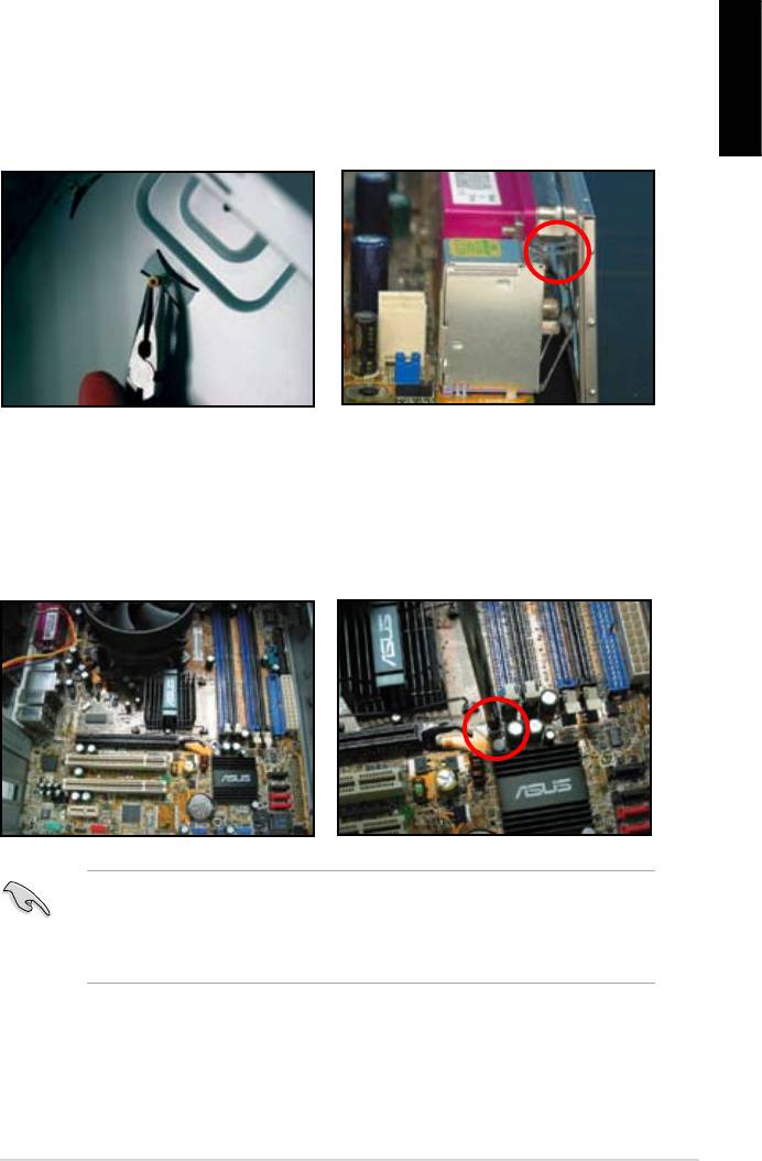
Place six screws into the holes indicated by circles to secure the motherboard to the chassis. Do not overtighten the screws! Doing so can damage the motherboard. Place this side towards the rear of the chassis P5KPL-AM SE ASUS P5KPL-AM SE…
-
Page 16: Motherboard Layout
USB34 LAN1_USB12 Intel ® CHA_FAN AUDIO 8102EL PCIEX16 Lithium Cell Intel ® CMOS Power Super ICH7 P5KPL-AM SE PCIEX1_1 SPEAKER PCI1 CLRTC ALC662 BIOS USBPW5-8 F_PANEL SB_PWR USB56 USB78 PRI_IDE AAFP Refer to section 1.10 Connectors for more information about rear panel connectors and internal connectors.
-
Page 17: Layout Contents
Contact your retailer immediately if the PnP cap is missing, or if you see any damage to the PnP cap/socket contacts/motherboard components. ASUS will shoulder the cost of repair only if the damage is shipment/ transit-related.
-
Page 18: Installing The Cpu
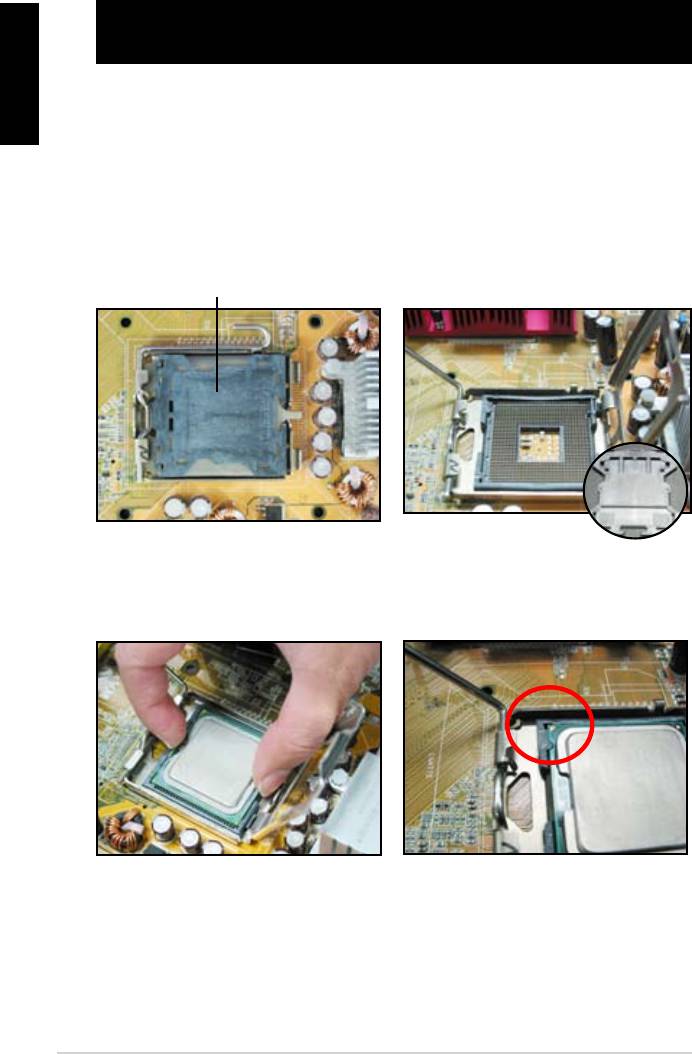
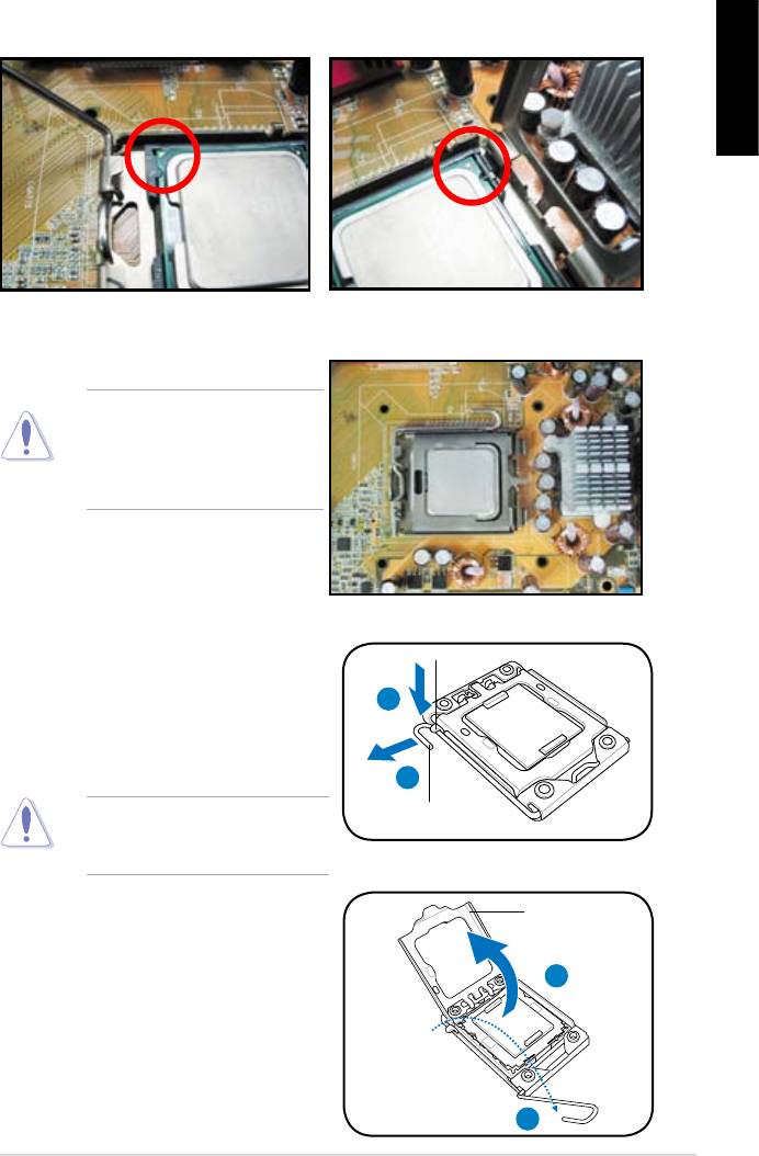
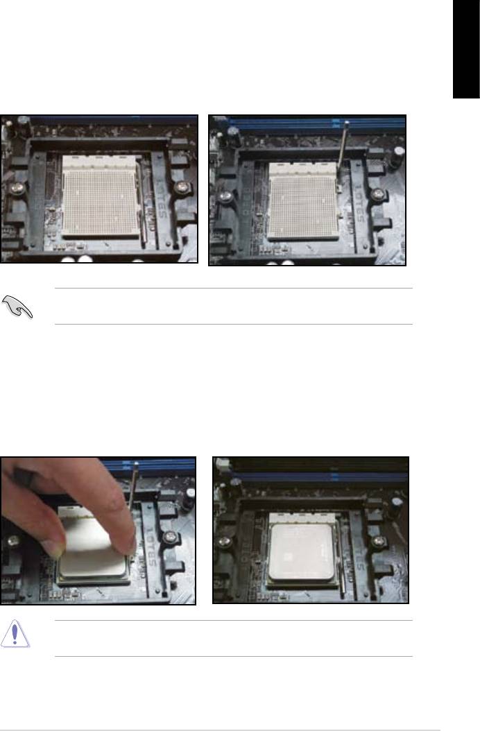
To install a CPU: Locate the CPU socket on the motherboard. P5KPL-AM SE P5KPL-AM SE CPU socket 775 Before installing the CPU, ensure that the socket box is facing towards you and the load lever is on your left. Press the load lever with your thumb…
-
Page 19
(B) until it snaps into the retention tab. The motherboard supports Intel ® LGA775 processors with the Intel Enhanced Intel SpeedStep ® ® Technology (EIST) and Hyper- Threading Technology. Refer to the Appendix for more information on these CPU features. ASUS P5KPL-AM SE… -
Page 20: Installing The Cpu Heatsink And Fan
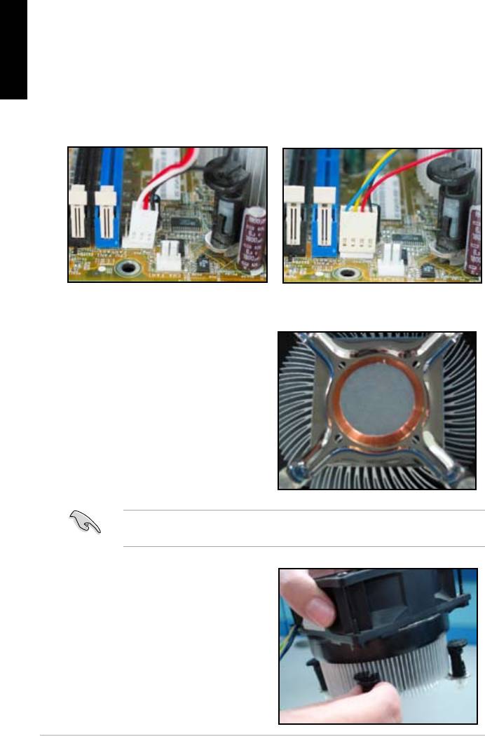
Do not forget to connect CPU FAN PWM the CPU fan connector! CPU FAN IN Hardware monitoring errors CPU FAN PWR can occur if you fail to plug this connector. P5KPL-AM SE P5KPL-AM SE CPU fan connector 1-10 Chapter 1: Product introduction…
-
Page 21: Uninstalling The Cpu Heatsink And Fan
Overview The motherboard comes with two Double Data Rate 2 (DDR2) Dual Inline Memory Modules (DIMM) sockets. The figure illustrates the location of the DDR2 DIMM sockets: P5KPL-AM SE P5KPL-AM SE 240-pin DDR2 DIMM sockets Channel Sockets Channel A DIMM_A1…
-
Page 22: Memory Configurations
1.7.2 Memory configurations You may install 256 MB, 512 MB, 1 GB and 2 GB unbuffered non-ECC DDR2 DIMMs into the DIMM sockets. • You may install varying memory sizes in Channel A and Channel B. The system maps the total size of the lower-sized channel for the dual-channel configuration. Any excess memory from the higher-sized channel is then mapped for single-channel operation.
-
Page 23
• DDR2-667U 1G Hynix HY5PS12821BFP-E3 A • • 512MB AENEON AET660UD00-30DA98Z AENEON AET93F30DA 0552 • • 512MB AENEON AET660UD00-30DB97X AENEON AET93R300B 0634 • • AENEON AET760UD00-30DA98Z AENEON AET93F30DA8EE47414G 0540 • • (continued on the next page) ASUS P5KPL-AM SE 1-13… -
Page 24
DIMM support S S / Size Vendor Model Brand Component AENEON AET760UD00-30DA98Z AENEON AET93F30DA 0604 • • AENEON AET760UD00-30DB97X AENEON AET93R300B 0639 • • 512MB TAKEMS TMS51B264C081-665QI takeMS MS18T51280-3 • • 512MB TAKEMS TMS51B264C081-665AP takeMS MS18T51280-3S0627D • • TAKEMS TMS1GB264C081-665QI takeMS MS18T51280-3 •… -
Page 25
Kingbox EP512D21066PS Micron 6QD22D9GCT • • Visit the ASUS website at (www.asus.com) for the latest QVL. SS — Single-sided / DS — Double — sided DIMM support: • A*: Supports one module inserted into any slot as Single-channel memory configuration. -
Page 26: Installing A Dimm
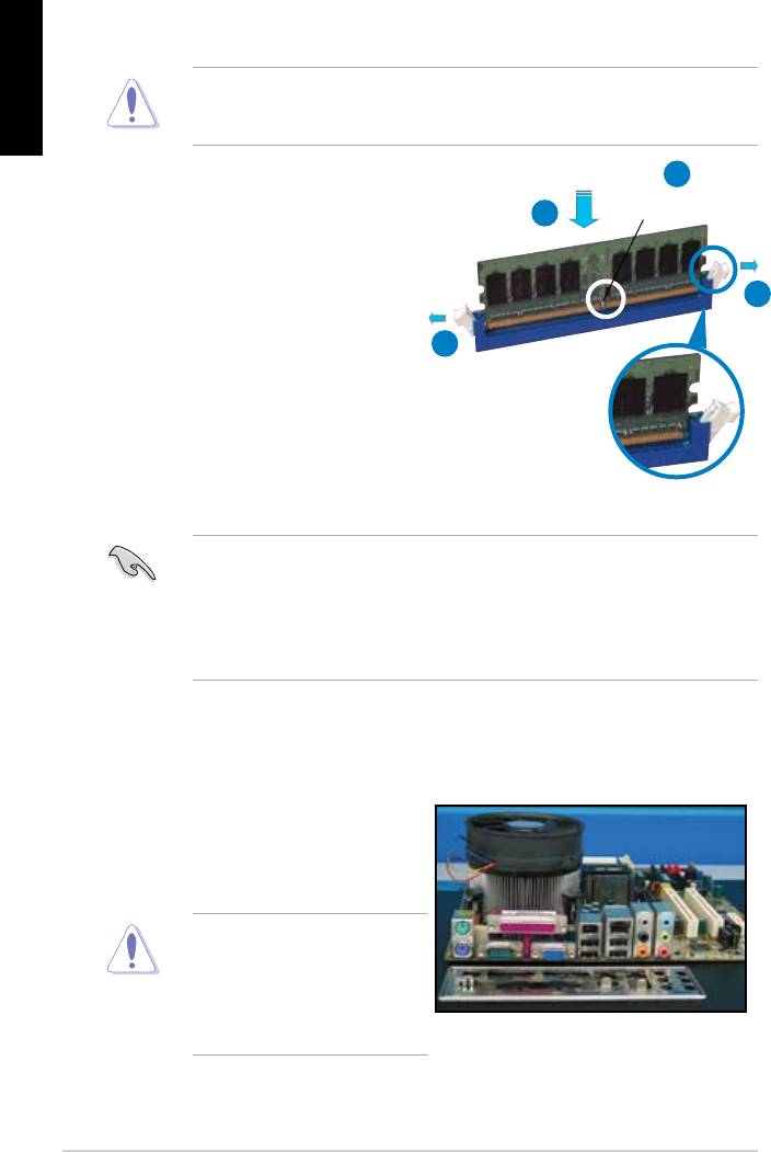
1.7.3 Installing a DIMM Unplug the power supply before adding or removing DIMMs or other system components. Failure to do so may cause severe damage to both the motherboard and the components. To install a DIMM: DDR2 DIMM notch Press the retaining clips outward to unlock a DDR2 DIMM socket.
-
Page 27: Expansion Slots
This motherboard supports PCI Express x1 network cards, SCSI cards and other cards that comply with the PCI Express specifications. 1.8.5 PCI Express x16 slot This motherboard supports a PCI Express x16 graphics card that complies with the PCI Express specifications. ASUS P5KPL-AM SE 1-17…
-
Page 28: Jumpers
Normal Clear RTC (Default) P5KPL-AM SE Clear RTC RAM • If the steps above do not help, remove the onboard battery and move the jumper again to clear the CMOS RTC RAM data. After the CMOS clearance, reinstall the battery.
-
Page 29
+5VSB P5KPL-AM SE (Default) P5KPL-AM SE USB Device Wake Up • The USB device wake-up feature requires a power supply that can provide 500mA on the +5VSB lead for the USB port. Otherwise, the system would not power up. • The total current consumed must NOT exceed the power supply capability (+5VSB) whether under normal condition or in sleep mode. -
Page 30: Connectors
1.10 Connectors 1.10.1 Rear panel connectors PS/2 mouse port (green). This port is for a PS/2 mouse. LAN (RJ-45) port. Supported by Realtek 10/100 LAN controller, this port allows 10/100 connection to a Local Area Network (LAN) through a network hub. Refer to the table below for the LAN port LED indications.
-
Page 31: Internal Connectors
RSATA_TXP1 RSATA_RXN2 RSATA_RXN1 P5KPL-AM SE RSATA_RXP2 RSATA_RXP1 P5KPL-AM SE SATA connectors (ICH10R ® right angle side Connect the right-angle side of SATA signal cable to SATA device. You may also connect the right-angle side of SATA cable to the onboard SATA port to avoid mechanical conflict with huge graphics cards.
-
Page 32
P5KPL-AM SE IDE connector Optical drive audio connector (4-pin CD) These connectors allow you to receive stereo audio input from sound sources such as a CD-ROM, TV tuner, or MPEG card. P5KPL-AM SE P5KPL-AM SE Internal audio connector 1-22 Chapter 1: Product introduction… -
Page 33
Never connect a 1394 cable to the USB connectors. Doing so will damage the motherboard! You can connect the front panel USB cable to the ASUS Q-Connector (USB, blue) first, and then install the Q-Connector (USB) to the USB connector onboard if your chassis supports front panel USB ports. -
Page 34
+12V P5KPL-AM SE P5KPL-AM SE fan connectors Only the CPU_FAN connector support the ASUS Advanced Q-Fan feature. Speaker connector (4-pin SPEAKER) This 4-pin connector is for the chassis-mounted system warning speaker. The speaker allows you to hear system beeps and warnings. -
Page 35
+3 Volts PIN 1 P5KPL-AM SE ATX power connectors • For a fully configured system, we recommend that you use a power supply unit (PSU) that complies with ATX 12 V Specification 2.0 (or later version) and provides a minimum power of 400 W. -
Page 36: System Panel Connector
PIN 1 P5KPL-AM SE HD_LED RESET P5KPL-AM SE System panel connector System power LED (2-pin PWRLED) • This 2-pin connector is for the system power LED. Connect the chassis power LED cable to this connector. The system power LED lights up when you turn on the system power, and blinks when the system is in sleep mode.
-
Page 37: Software Support
Click an item to install If Autorun is NOT enabled in your computer, browse the contents of the Support DVD to locate the file ASSETUP.EXE from the BIN folder. Double-click the ASSETUP.EXE to run the DVD. ASUS P5KPL-AM SE 1-27…
-
Page 38
1-28 Chapter 1: Product introduction… -
Page 39: Managing And Updating Your Bios
The following utilities allow you to manage and update the motherboard Basic Input/Output System (BIOS) setup. ASUS EZ Flash 2 (Updates the BIOS in DOS mode using a floppy disk or USB flash disk.) ASUS AFUDOS (Updates the BIOS in DOS mode using a bootable floppy disk.) ASUS CrashFree BIOS 3 (Updates the BIOS using a bootable floppy disk, USB flash disk or the motherboard support DVD when the BIOS file fails or gets corrupted.)
-
Page 40: Creating A Bootable Floppy Disk
ASUSUpdate. Select Update BIOS from the Internet from the drop-down menu, then click Next. Select the ASUS FTP site nearest you to avoid network traffic, or click Auto Select then click Next. From the FTP site, select the BIOS version that you wish to download then click Next.
-
Page 41: Asus Ez Flash 2 Utility
ASUS EZ Flash 2 utility The ASUS EZ Flash 2 feature allows you to update the BIOS without having to go through the long process of booting from a floppy disk and using a DOS-based utility. The EZ Flash 2 utility is built in the BIOS chip so it is accessible by pressing <Alt>…
-
Page 42: Afudos Utility
Updating the BIOS file To update the BIOS file using the AFUDOS utility: Visit the ASUS website (at www.asus.com) and download the latest BIOS file for the motherboard. Save the BIOS file to a bootable floppy disk. We recommend that you write the BIOS filename on a piece of paper. You will need to key in the exact BIOS filename at the DOS prompt later.
-
Page 43: Asus Crashfree Bios 3 Utility
2.1.5 ASUS CrashFree BIOS 3 utility The ASUS CrashFree BIOS 3 is an auto recovery tool that allows you to restore the BIOS file when it fails or gets corrupted during the updating process. You can update a corrupted BIOS file using the motherboard support DVD, a floppy disk or a USB flash disk that contains the updated BIOS file.
-
Page 44
Restart the system after the utility completes the updating process. The recovered BIOS may not be the latest BIOS version for this motherboard. Visit the ASUS website (at www.asus.com) to download the latest BIOS file. Recovering the BIOS from a USB flash disk To recover the BIOS from a USB flash disk: Insert a USB flash disk that contains BIOS file to the USB port. -
Page 45: Bios Setup Program
Restart the system after the utility completes the updating process. • Only the USB flash disk with FAT 32/16 format and single partition can support ASUS CrashFree BIOS 3. The device size should be smaller than 8GB. • DO NOT shut down or reset the system while updating the BIOS! Doing so can cause…
-
Page 46: Bios Menu Screen
2.2.1 BIOS menu screen Menu items Menu bar Configuration fields General help BIOS SETUP UTILITY Main Advanced Power Boot Tools Exit Use [ENTER], [TAB] or System Time [14:14:35] [SHIFT-TAB] to select System Date [Wed 04/16/2008] a field. Use [+] or [-] to configure system time.
-
Page 47: Menu Items
Pop-up window <Page Up> /<Page Down> keys to Scroll bar display the other items on the screen. 2.2.9 General help At the top right corner of the menu screen is a brief description of the selected item. ASUS P5KPL-AM SE…
-
Page 48: Main Menu
Main menu When you enter the BIOS Setup program, the Main menu screen appears, giving you an overview of the basic system information. Refer to section 2.2.1 BIOS menu screen for information on the menu screen items and how to navigate through them. BIOS SETUP UTILITY Main Advanced…
-
Page 49: Sata 1 And Sata 2
Storage Configuration The items in this menu allow you to set or change the configurations for the SATA devices installed in the system. Select an item then press <Enter> if you want to configure the item. ASUS P5KPL-AM SE 2-11…
-
Page 50: System Information
ATA/IDE Configuration [Enhanced] Configuration options: [Disabled] [Compatible] [Enhanced] Enhanced Mode Support On [S-ATA] Configuration options: [S-ATA+P-ATA] [S-ATA] [P-ATA] IDE Detect Time Out [35] Selects the time out value for detecting ATA/ATAPI devices. Configuration options: [0] [5] [10] [15] [20] [25] [30] [35] 2.3.6 System Information This menu gives you an overview of the general system specifications.
-
Page 51
Manually set memory voltage or set to Auto for safe mode. Configuration options: [Auto] [1.80V] [2.00V] [2.25V] VTT_CPU Over Voltage [Auto] Manually set FSB Termination Voltage or set to Auto for safe mode. Configuration options: [Auto] [1.2V] [1.3V] ASUS P5KPL-AM SE 2-13… -
Page 52: Usb Configuration
1.25V Over Voltage [Auto] Manually set MCH Chipset Voltage or set to Auto for safe mode. Configuration options: [Auto] [1.25V] [1.4V] 1.5V Over Voltage [Auto] Manually set ICH Chipset Voltage or set to Auto for safe mode. Configuration options: [Auto] [1.5V] [1.6V] 2.4.2 USB Configuration The items in this menu allows you to change the USB-related features.
-
Page 53: Chipset
Allows you to decide which graphics controller to use as the primary boot device. Configuration options: [IGD] [PCI/IGD] [PCI/PEG] [PEG/IGD] [PEG/PCI] Internal Graphics Mode Select [Enabled, 8MB] Allows you to select the amout of system memory used by the Interanal graphics device. Configuration options: [Disabled] [Enabled, 1MB] [Enabled, 8MB] ASUS P5KPL-AM SE 2-15…
-
Page 54: Onboard Devices Configuration
PEG Port Configuration PEG Force x1 [Disabled] Allows you to enable or disable the PEG Forec x 1. Configuration options: [Enabled] [Disabled] Video Function Configuration DVMT Mode Select [DVMT Mode] Allows you to select the DVMT Mode. Configuration options: [Fixed Mode] [DVMT Mode] DVMT/FIXED Memory [256MB] Allows you to select the amount of the DVMT/FIXED Memory.
-
Page 55: Power Menu
[Auto] — Detected by OS. 2.5.2 ACPI 2.0 Support [Disabled] Allows you to add more tables for Advanced Configuration and Power Interface (ACPI) 2.0 specifications. Configuration options: [Disabled] [Enabled] ASUS P5KPL-AM SE 2-17…
-
Page 56: Acpi Apic Support
2.5.3 ACPI APIC Support [Enabled] Allows you to enable or disable the Advanced Configuration and Power Interface (ACPI) support in the Advanced Programmable Interrupt Controller (APIC). When set to Enabled, the ACPI APIC table pointer is included in the RSDT pointer list. Configuration options: [Disabled] [Enabled] 2.5.4 APM Configuration…
-
Page 57: Boot Menu
These items specify the boot device priority sequence from the available devices. The number of device items that appears on the screen depends on the number of devices installed in the system. Configuration options: [Hard Drive] [Removable Dev.] [ATAPI CD-ROM] [Disabled] ASUS P5KPL-AM SE 2-19…
-
Page 58: Boot Settings Configuration
POST items. Configuration options: [Disabled] [Enabled] Full Screen Logo [Enabled] This allows you to enable or disable the full screen logo display feature. Configuration options: [Disabled] [Enabled] Set this item to [Enabled] to use the ASUS MyLogo2 feature. ™ AddOn ROM Display Mode [Force BIOS] Sets the display mode for option ROM.
-
Page 59: Change User Password
Password Check [Setup] When set to [Setup], BIOS checks for user password when accessing the Setup utility. When set to [Always], BIOS checks for user password both when accessing Setup and booting the system. Configuration options: [Setup] [Always] ASUS P5KPL-AM SE 2-21…
-
Page 60: Tools Menu
2.7.1 ASUS EZ Flash 2 Allows you to run ASUS EZ Flash 2. When you press <Enter>, a confirmation message appears. Use the left/right arrow key to select between [Yes] or [No], then press <Enter> to confirm your choice. Please see section 2.1.3 for details.
-
Page 61: Discard Changes
When you select this option or if you press <F5>, a confirmation window appears. Select OK to load default values. Select Exit & Save Changes or make other changes before saving the values to the non-volatile RAM. ASUS P5KPL-AM SE 2-23…
-
Page 62
2-24 Chapter 2: BIOS setup…
Руководства пользователя
Версия A4323A
3.24 MB
P5KPL-AM SE Asian Quick Start Guide for Multiple Languages
Версия T4810
1.32 MB
P5KPL-AM SE user’s manual (Traditional Chinese)
Версия C4810
1.45 MB
P5KPL-AM SE user’s manual (Simplified Chinese)
Версия E4810
1.06 MB
P5KPL-AM SE user’s manual (English)
Версия T4204
1.97 MB
Motherboard Installation Guide (Traditional Chinese)
Версия C4204
1.83 MB
Motherboard Installation Guide (Simplified Chinese)
Версия U4323
1019.34 KB
P5KPL-AM SE European Quick Start Guide for Multiple Languages
Версия E4323
1.07 MB
P5KPL-AM SE user’s manual(English)
Версия F4236
1.23 MB
P5KPL-AM SE user’s manual(French)
Версия E4236
1.37 MB
P5KPL-AM SE user’s manual(English)
- Manuals
- Brands
- Asus Manuals
- Motherboard
- P5KPL-AM — SE Motherboard And Intel Core 2…
- User manual
-
Contents
-
Table of Contents
-
Bookmarks
Quick Links
Related Manuals for Asus P5KPL-AM SE
Summary of Contents for Asus P5KPL-AM SE
-
Page 1
P5KPL-AM SE… -
Page 2
Product warranty or service will not be extended if: (1) the product is repaired, modified or altered, unless such repair, modification of alteration is authorized in writing by ASUS; or (2) the serial number of the product is defaced or missing. -
Page 3: Table Of Contents
Contents Notices ………………….vi Safety information ………………vii About this guide ………………viii P5KPL-AM SE specifications summary …………. x Chapter 1: Product introduction Welcome! ………………1-1 Package contents …………….. 1-1 Special features …………….1-1 1.3.1 Product highlights …………1-1 1.3.2 ASUS Special features ………..
-
Page 4
2.1.1 ASUS Update utility …………2-1 2.1.2 Creating a bootable floppy disk ……..2-2 2.1.3 ASUS EZ Flash 2 utility ……….. 2-3 2.1.4 AFUDOS utility …………..2-4 2.1.5 ASUS CrashFree BIOS 3 utility ……..2-5 BIOS setup program …………..2-7 2.2.1… -
Page 5
Boot menu ……………… 2-19 2.6.1 Boot Device Priority …………2-19 2.6.2 Boot Settings Configuration ………. 2-20 2.6.3 Security …………….. 2-20 Tools menu …………….. 2-22 2.7.1 ASUS EZ Flash 2 …………2-22 2.7.2 AI NET 2……………. 2-22 Exit menu ………………2-22… -
Page 6: Notices
Notices Federal Communications Commission Statement This device complies with Part 15 of the FCC Rules. Operation is subject to the following two conditions: • This device may not cause harmful interference, and • This device must accept any interference received including interference that may cause undesired operation.
-
Page 7: Safety Information
Safety information Electrical safety • To prevent electrical shock hazard, disconnect the power cable from the electrical outlet before relocating the system. • When adding or removing devices to or from the system, ensure that the power cables for the devices are unplugged before the signal cables are connected. If possible, disconnect all power cables from the existing system before you add a device.
-
Page 8: Conventions Used In This Guide
Refer to the following sources for additional information and for product and software updates. ASUS websites The ASUS website provides updated information on ASUS hardware and software products. Refer to the ASUS contact information. Optional documentation Your product package may include optional documentation, such as warranty flyers, that may have been added by your dealer.
-
Page 9: P5Kpl-Am Se Specifications Summary
® Processors Compatible with Intel 05B / 05A / 06 processors ® Intel Hyper-Threading Technology ready ® (Refer to www.asus.com for Intel CPU support list) Chipset Northbridge: Intel ® Southbridge: Intel ICH7 ® Front Side Bus 1600(O.C.) / 1333 / 1066 / 800 / 533MHz…
-
Page 10
SFS (Stepless Frequency Selection) Overclocking Features — FSB turning from 133MHz up to 600MHz at 1MHz increment. Overclocking Protection: — ASUS C.P.R. (CPU Parameter Recall) BIOS features 8 Mb Flash ROM, AMI BIOS, PnP, DMI2.0, WfM2.0, ACPI V2.0a, SM BIOS 2.5 Manageability… -
Page 11: Chapter 1: Product Introduction
Green ASUS This motherboard and its packaging comply with the European Union’s Restriction on the use of Hazardous Substances (RoHS). This is in line with the ASUS vision of creating environment-friendly and recyclable products/packaging to safeguard consumers’ health while minimizing the impact on the environment.
-
Page 12
PCs e.g., Gigabit LAN, 1394b, and high-speed RAID systems. FSB 1600 support (O.C.) ASUS’s exclusive overclocking design now unleashes the ultimate potential of the Intel Core ® ™2 processor. With the new Intel 45nm micro-architecture technology and FSB 1600 (O.C.) / 1333 / 1066 / 800 MHz, this motherboard allows you to enjoy the latest technology supported by one of the most powerful and energy efficient CPUs in the world. -
Page 13: Asus Special Features
Simply restore corrupted BIOS data from USB flash disk The ASUS CrashFree BIOS 3 allows users to restore corrupted BIOS data from a USB flash disk containing the BIOS file. This utility saves users the cost and hassle of buying a replacement BIOS chip.
-
Page 14: Before You Proceed
The illustration below shows the location of the onboard LED. SB_PWR P5KPL-AM SE Standy Power Powered Off P5KPL-AM SE Onboard LED Chapter 1: Product introduction…
-
Page 15: Motherboard Overview
Place six screws into the holes indicated by circles to secure the motherboard to the chassis. Do not overtighten the screws! Doing so can damage the motherboard. Place this side towards the rear of the chassis P5KPL-AM SE ASUS P5KPL-AM SE…
-
Page 16: Motherboard Layout
USB34 LAN1_USB12 Intel ® CHA_FAN AUDIO 8102EL PCIEX16 Lithium Cell Intel ® CMOS Power Super ICH7 P5KPL-AM SE PCIEX1_1 SPEAKER PCI1 CLRTC ALC662 BIOS USBPW5-8 F_PANEL SB_PWR USB56 USB78 PRI_IDE AAFP Refer to section 1.10 Connectors for more information about rear panel connectors and internal connectors.
-
Page 17: Layout Contents
Contact your retailer immediately if the PnP cap is missing, or if you see any damage to the PnP cap/socket contacts/motherboard components. ASUS will shoulder the cost of repair only if the damage is shipment/ transit-related.
-
Page 18: Installing The Cpu
To install a CPU: Locate the CPU socket on the motherboard. P5KPL-AM SE P5KPL-AM SE CPU socket 775 Before installing the CPU, ensure that the socket box is facing towards you and the load lever is on your left. Press the load lever with your thumb…
-
Page 19
(B) until it snaps into the retention tab. The motherboard supports Intel ® LGA775 processors with the Intel Enhanced Intel SpeedStep ® ® Technology (EIST) and Hyper- Threading Technology. Refer to the Appendix for more information on these CPU features. ASUS P5KPL-AM SE… -
Page 20: Installing The Cpu Heatsink And Fan
Do not forget to connect CPU FAN PWM the CPU fan connector! CPU FAN IN Hardware monitoring errors CPU FAN PWR can occur if you fail to plug this connector. P5KPL-AM SE P5KPL-AM SE CPU fan connector 1-10 Chapter 1: Product introduction…
-
Page 21: Uninstalling The Cpu Heatsink And Fan
Overview The motherboard comes with two Double Data Rate 2 (DDR2) Dual Inline Memory Modules (DIMM) sockets. The figure illustrates the location of the DDR2 DIMM sockets: P5KPL-AM SE P5KPL-AM SE 240-pin DDR2 DIMM sockets Channel Sockets Channel A DIMM_A1…
-
Page 22: Memory Configurations
1.7.2 Memory configurations You may install 256 MB, 512 MB, 1 GB and 2 GB unbuffered non-ECC DDR2 DIMMs into the DIMM sockets. • You may install varying memory sizes in Channel A and Channel B. The system maps the total size of the lower-sized channel for the dual-channel configuration. Any excess memory from the higher-sized channel is then mapped for single-channel operation.
-
Page 23
• DDR2-667U 1G Hynix HY5PS12821BFP-E3 A • • 512MB AENEON AET660UD00-30DA98Z AENEON AET93F30DA 0552 • • 512MB AENEON AET660UD00-30DB97X AENEON AET93R300B 0634 • • AENEON AET760UD00-30DA98Z AENEON AET93F30DA8EE47414G 0540 • • (continued on the next page) ASUS P5KPL-AM SE 1-13… -
Page 24
DIMM support S S / Size Vendor Model Brand Component AENEON AET760UD00-30DA98Z AENEON AET93F30DA 0604 • • AENEON AET760UD00-30DB97X AENEON AET93R300B 0639 • • 512MB TAKEMS TMS51B264C081-665QI takeMS MS18T51280-3 • • 512MB TAKEMS TMS51B264C081-665AP takeMS MS18T51280-3S0627D • • TAKEMS TMS1GB264C081-665QI takeMS MS18T51280-3 •… -
Page 25
Kingbox EP512D21066PS Micron 6QD22D9GCT • • Visit the ASUS website at (www.asus.com) for the latest QVL. SS — Single-sided / DS — Double — sided DIMM support: • A*: Supports one module inserted into any slot as Single-channel memory configuration. -
Page 26: Installing A Dimm
1.7.3 Installing a DIMM Unplug the power supply before adding or removing DIMMs or other system components. Failure to do so may cause severe damage to both the motherboard and the components. To install a DIMM: DDR2 DIMM notch Press the retaining clips outward to unlock a DDR2 DIMM socket.
-
Page 27: Expansion Slots
This motherboard supports PCI Express x1 network cards, SCSI cards and other cards that comply with the PCI Express specifications. 1.8.5 PCI Express x16 slot This motherboard supports a PCI Express x16 graphics card that complies with the PCI Express specifications. ASUS P5KPL-AM SE 1-17…
-
Page 28: Jumpers
Normal Clear RTC (Default) P5KPL-AM SE Clear RTC RAM • If the steps above do not help, remove the onboard battery and move the jumper again to clear the CMOS RTC RAM data. After the CMOS clearance, reinstall the battery.
-
Page 29
+5VSB P5KPL-AM SE (Default) P5KPL-AM SE USB Device Wake Up • The USB device wake-up feature requires a power supply that can provide 500mA on the +5VSB lead for the USB port. Otherwise, the system would not power up. • The total current consumed must NOT exceed the power supply capability (+5VSB) whether under normal condition or in sleep mode. -
Page 30: Connectors
1.10 Connectors 1.10.1 Rear panel connectors PS/2 mouse port (green). This port is for a PS/2 mouse. LAN (RJ-45) port. Supported by Realtek 10/100 LAN controller, this port allows 10/100 connection to a Local Area Network (LAN) through a network hub. Refer to the table below for the LAN port LED indications.
-
Page 31: Internal Connectors
RSATA_TXP1 RSATA_RXN2 RSATA_RXN1 P5KPL-AM SE RSATA_RXP2 RSATA_RXP1 P5KPL-AM SE SATA connectors (ICH10R ® right angle side Connect the right-angle side of SATA signal cable to SATA device. You may also connect the right-angle side of SATA cable to the onboard SATA port to avoid mechanical conflict with huge graphics cards.
-
Page 32
P5KPL-AM SE IDE connector Optical drive audio connector (4-pin CD) These connectors allow you to receive stereo audio input from sound sources such as a CD-ROM, TV tuner, or MPEG card. P5KPL-AM SE P5KPL-AM SE Internal audio connector 1-22 Chapter 1: Product introduction… -
Page 33
Never connect a 1394 cable to the USB connectors. Doing so will damage the motherboard! You can connect the front panel USB cable to the ASUS Q-Connector (USB, blue) first, and then install the Q-Connector (USB) to the USB connector onboard if your chassis supports front panel USB ports. -
Page 34
+12V P5KPL-AM SE P5KPL-AM SE fan connectors Only the CPU_FAN connector support the ASUS Advanced Q-Fan feature. Speaker connector (4-pin SPEAKER) This 4-pin connector is for the chassis-mounted system warning speaker. The speaker allows you to hear system beeps and warnings. -
Page 35
+3 Volts PIN 1 P5KPL-AM SE ATX power connectors • For a fully configured system, we recommend that you use a power supply unit (PSU) that complies with ATX 12 V Specification 2.0 (or later version) and provides a minimum power of 400 W. -
Page 36: System Panel Connector
PIN 1 P5KPL-AM SE HD_LED RESET P5KPL-AM SE System panel connector System power LED (2-pin PWRLED) • This 2-pin connector is for the system power LED. Connect the chassis power LED cable to this connector. The system power LED lights up when you turn on the system power, and blinks when the system is in sleep mode.
-
Page 37: Software Support
Click an item to install If Autorun is NOT enabled in your computer, browse the contents of the Support DVD to locate the file ASSETUP.EXE from the BIN folder. Double-click the ASSETUP.EXE to run the DVD. ASUS P5KPL-AM SE 1-27…
-
Page 38
1-28 Chapter 1: Product introduction… -
Page 39: Managing And Updating Your Bios
The following utilities allow you to manage and update the motherboard Basic Input/Output System (BIOS) setup. ASUS EZ Flash 2 (Updates the BIOS in DOS mode using a floppy disk or USB flash disk.) ASUS AFUDOS (Updates the BIOS in DOS mode using a bootable floppy disk.) ASUS CrashFree BIOS 3 (Updates the BIOS using a bootable floppy disk, USB flash disk or the motherboard support DVD when the BIOS file fails or gets corrupted.)
-
Page 40: Creating A Bootable Floppy Disk
ASUSUpdate. Select Update BIOS from the Internet from the drop-down menu, then click Next. Select the ASUS FTP site nearest you to avoid network traffic, or click Auto Select then click Next. From the FTP site, select the BIOS version that you wish to download then click Next.
-
Page 41: Asus Ez Flash 2 Utility
ASUS EZ Flash 2 utility The ASUS EZ Flash 2 feature allows you to update the BIOS without having to go through the long process of booting from a floppy disk and using a DOS-based utility. The EZ Flash 2 utility is built in the BIOS chip so it is accessible by pressing <Alt>…
-
Page 42: Afudos Utility
Updating the BIOS file To update the BIOS file using the AFUDOS utility: Visit the ASUS website (at www.asus.com) and download the latest BIOS file for the motherboard. Save the BIOS file to a bootable floppy disk. We recommend that you write the BIOS filename on a piece of paper. You will need to key in the exact BIOS filename at the DOS prompt later.
-
Page 43: Asus Crashfree Bios 3 Utility
2.1.5 ASUS CrashFree BIOS 3 utility The ASUS CrashFree BIOS 3 is an auto recovery tool that allows you to restore the BIOS file when it fails or gets corrupted during the updating process. You can update a corrupted BIOS file using the motherboard support DVD, a floppy disk or a USB flash disk that contains the updated BIOS file.
-
Page 44
Restart the system after the utility completes the updating process. The recovered BIOS may not be the latest BIOS version for this motherboard. Visit the ASUS website (at www.asus.com) to download the latest BIOS file. Recovering the BIOS from a USB flash disk To recover the BIOS from a USB flash disk: Insert a USB flash disk that contains BIOS file to the USB port. -
Page 45: Bios Setup Program
Restart the system after the utility completes the updating process. • Only the USB flash disk with FAT 32/16 format and single partition can support ASUS CrashFree BIOS 3. The device size should be smaller than 8GB. • DO NOT shut down or reset the system while updating the BIOS! Doing so can cause…
-
Page 46: Bios Menu Screen
2.2.1 BIOS menu screen Menu items Menu bar Configuration fields General help BIOS SETUP UTILITY Main Advanced Power Boot Tools Exit Use [ENTER], [TAB] or System Time [14:14:35] [SHIFT-TAB] to select System Date [Wed 04/16/2008] a field. Use [+] or [-] to configure system time.
-
Page 47: Menu Items
Pop-up window <Page Up> /<Page Down> keys to Scroll bar display the other items on the screen. 2.2.9 General help At the top right corner of the menu screen is a brief description of the selected item. ASUS P5KPL-AM SE…
-
Page 48: Main Menu
Main menu When you enter the BIOS Setup program, the Main menu screen appears, giving you an overview of the basic system information. Refer to section 2.2.1 BIOS menu screen for information on the menu screen items and how to navigate through them. BIOS SETUP UTILITY Main Advanced…
-
Page 49: Sata 1 And Sata 2
Storage Configuration The items in this menu allow you to set or change the configurations for the SATA devices installed in the system. Select an item then press <Enter> if you want to configure the item. ASUS P5KPL-AM SE 2-11…
-
Page 50: System Information
ATA/IDE Configuration [Enhanced] Configuration options: [Disabled] [Compatible] [Enhanced] Enhanced Mode Support On [S-ATA] Configuration options: [S-ATA+P-ATA] [S-ATA] [P-ATA] IDE Detect Time Out [35] Selects the time out value for detecting ATA/ATAPI devices. Configuration options: [0] [5] [10] [15] [20] [25] [30] [35] 2.3.6 System Information This menu gives you an overview of the general system specifications.
-
Page 51
Manually set memory voltage or set to Auto for safe mode. Configuration options: [Auto] [1.80V] [2.00V] [2.25V] VTT_CPU Over Voltage [Auto] Manually set FSB Termination Voltage or set to Auto for safe mode. Configuration options: [Auto] [1.2V] [1.3V] ASUS P5KPL-AM SE 2-13… -
Page 52: Usb Configuration
1.25V Over Voltage [Auto] Manually set MCH Chipset Voltage or set to Auto for safe mode. Configuration options: [Auto] [1.25V] [1.4V] 1.5V Over Voltage [Auto] Manually set ICH Chipset Voltage or set to Auto for safe mode. Configuration options: [Auto] [1.5V] [1.6V] 2.4.2 USB Configuration The items in this menu allows you to change the USB-related features.
-
Page 53: Chipset
Allows you to decide which graphics controller to use as the primary boot device. Configuration options: [IGD] [PCI/IGD] [PCI/PEG] [PEG/IGD] [PEG/PCI] Internal Graphics Mode Select [Enabled, 8MB] Allows you to select the amout of system memory used by the Interanal graphics device. Configuration options: [Disabled] [Enabled, 1MB] [Enabled, 8MB] ASUS P5KPL-AM SE 2-15…
-
Page 54: Onboard Devices Configuration
PEG Port Configuration PEG Force x1 [Disabled] Allows you to enable or disable the PEG Forec x 1. Configuration options: [Enabled] [Disabled] Video Function Configuration DVMT Mode Select [DVMT Mode] Allows you to select the DVMT Mode. Configuration options: [Fixed Mode] [DVMT Mode] DVMT/FIXED Memory [256MB] Allows you to select the amount of the DVMT/FIXED Memory.
-
Page 55: Power Menu
[Auto] — Detected by OS. 2.5.2 ACPI 2.0 Support [Disabled] Allows you to add more tables for Advanced Configuration and Power Interface (ACPI) 2.0 specifications. Configuration options: [Disabled] [Enabled] ASUS P5KPL-AM SE 2-17…
-
Page 56: Acpi Apic Support
2.5.3 ACPI APIC Support [Enabled] Allows you to enable or disable the Advanced Configuration and Power Interface (ACPI) support in the Advanced Programmable Interrupt Controller (APIC). When set to Enabled, the ACPI APIC table pointer is included in the RSDT pointer list. Configuration options: [Disabled] [Enabled] 2.5.4 APM Configuration…
-
Page 57: Boot Menu
These items specify the boot device priority sequence from the available devices. The number of device items that appears on the screen depends on the number of devices installed in the system. Configuration options: [Hard Drive] [Removable Dev.] [ATAPI CD-ROM] [Disabled] ASUS P5KPL-AM SE 2-19…
-
Page 58: Boot Settings Configuration
POST items. Configuration options: [Disabled] [Enabled] Full Screen Logo [Enabled] This allows you to enable or disable the full screen logo display feature. Configuration options: [Disabled] [Enabled] Set this item to [Enabled] to use the ASUS MyLogo2 feature. ™ AddOn ROM Display Mode [Force BIOS] Sets the display mode for option ROM.
-
Page 59: Change User Password
Password Check [Setup] When set to [Setup], BIOS checks for user password when accessing the Setup utility. When set to [Always], BIOS checks for user password both when accessing Setup and booting the system. Configuration options: [Setup] [Always] ASUS P5KPL-AM SE 2-21…
-
Page 60: Tools Menu
2.7.1 ASUS EZ Flash 2 Allows you to run ASUS EZ Flash 2. When you press <Enter>, a confirmation message appears. Use the left/right arrow key to select between [Yes] or [No], then press <Enter> to confirm your choice. Please see section 2.1.3 for details.
-
Page 61: Discard Changes
When you select this option or if you press <F5>, a confirmation window appears. Select OK to load default values. Select Exit & Save Changes or make other changes before saving the values to the non-volatile RAM. ASUS P5KPL-AM SE 2-23…
-
Page 62
2-24 Chapter 2: BIOS setup…
Краткое содержание страницы № 1
P5KPL-AM SE
Motherboard
Краткое содержание страницы № 2
E4323 Second Edition V2 November 2008 Copyright © 2008 ASUSTeK Computer Inc. All Rights Reserved. No part of this manual, including the products and software described in it, may be reproduced, transmitted, transcribed, stored in a retrieval system, or translated into any language in any form or by any means, except documentation kept by the purchaser for backup purposes, without the express written permission of ASUSTeK Computer Inc. (“ASUS”). Product warranty or service will not be extende
Краткое содержание страницы № 3
Contents Notices ……………………………………………………………………………………………. v Safety information ………………………………………………………………………….. vi About this guide …………………………………………………………………………….. vi P5KPL-AM SE specifications summary ………………………………………….. viii Chapter 1: Product information 1.1 Before you proceed ……….
Краткое содержание страницы № 4
Contents 2.3.3 Primary IDE/SATA ………………………………………………….. 2-5 2.3.4 Storage Configuration …………………………………………….. 2-5 2.3.5 System Information ………………………………………………… 2-6 2.4 Advanced menu ………………………………………………………………… 2-6 2.4.1 JumperFree Configuration ………………………………………. 2-6 2.4.2 USB Configuration ………………………
Краткое содержание страницы № 5
Notices Federal Communications Commission Statement This device complies with Part 15 of the FCC Rules. Operation is subject to the following two conditions: • This device may not cause harmful interference, and • This device must accept any interference received including interference that may cause undesired operation. This equipment has been tested and found to comply with the limits for a Class B digital device, pursuant to Part 15 of the FCC Rules. These limits are designed to provide r
Краткое содержание страницы № 6
Safety information Electrical safety • To prevent electric shock hazard, disconnect the power cable from the electric outlet before relocating the system. • When adding or removing devices to or from the system, ensure that the power cables for the devices are unplugged before the signal cables are connected. If possible, disconnect all power cables from the existing system before you add a device. • Before connecting or removing signal cables from the motherboard, ensure that all power cabl
Краткое содержание страницы № 7
Conventions used in this guide To ensure that you perform certain tasks properly, take note of the following symbols used throughout this manual. DANGER/WARNING: Information to prevent injury to yourself when trying to complete a task. CAUTION: Information to prevent damage to the components when trying to complete a task. IMPORTANT: Instructions that you MUST follow to complete a task. NOTE: Tips and additional information to help you complete a task. Where to find more info
Краткое содержание страницы № 8
P5KPL-AM SE specifications summary ® CPU LGA775 socket for Intel Core™2 Quad/ Core™2 ® ® Extreme / Core™2 Duo / Pentium D / Pentium 4 / ® Celeron E1000 Series and Celeron 400 Series Processors ® Compatible with Intel 05B / 05A / 06 processors ® Intel Hyper-Threading Technology ready (Refer to www.asus.com for Intel CPU support list) ® Chipset Northbridge: Intel G31 ® Southbridge: Intel ICH7 Front Side Bus 1600(O.C.) / 1333 / 1066 / 800 / 533MHz Memory Dual channel memory architecture
Краткое содержание страницы № 9
P5KPL-AM SE specifications summary Internal connectors 2 x USB 2.0 connectors supports additional 4 USB ports 1 x internal speaker connector 2 x Serial ATA connectors 1 x CPU fan connector 1 x Chassis fan connector 1 x CD audio in connector 1 x 24-pin EATXPWR 12 V power connector 1 x 4-pin ATX 12 V power connector 1 x Front panel High Definition audio connector 1 x System Panel connector ASUS Exclusive SFS (Stepless Frequency Selection) Overclocking Features — FSB turning from 133MHz
Краткое содержание страницы № 10
Chapter 1 Product introduction ® Thank you for buying an ASUS P5KPL-AM SE motherboard! Before you start installing the motherboard, and hardware devices on it, check the items in your motherboard package. Refer to page ix for the list of accessories. If any of the items is damaged or missing, contact your retailer. 1.1 Before you proceed Take note of the following precautions before you install motherboard components or change any motherboard settings. • Unplug the power cord from the wall s
Краткое содержание страницы № 11
1.2 Motherboard overview 1.2.1 Motherboard layout Ensure that you install the motherboard into the chassis in the correct orientation. The edge with external ports goes to the rear part of the chassis. 18.3cm(7.2in) KBMS ATX12V CPU_FAN LGA775 USB34 Place this side towards LAN1_USB12 the rear of the chassis. ® Intel G31 CHA_FAN AUDIO RTL 8102FL PCIEX16 Lithium Cell CMOS Power ® Super Intel I/O ICH7 PCIEX1_1 P5KPL-AM SE SPEAKER PCI1 CLRTC ALC662 8Mb BIOS USBPW5-8 F_PANEL SB_PWR USB56 PRI_IDE US
Краткое содержание страницы № 12
1.3 Central Processing Unit (CPU) ® The motherboard comes with a surface mount LGA775 socket designed for the Intel Core ® ® ® ™2 Quad / Core™2 Extreme / Core™2 Duo / Pentium D / Pentium 4 and Celeron E1000 Series and Celeron 400 Series processors. • Ensure that all power cables are unplugged before installing the CPU. • Upon purchase of the motherboard, make sure that the PnP cap is on the socket and the socket contacts are not bent. Contact your retailer immediately if the PnP cap is miss
Краткое содержание страницы № 13
• You may install varying memory sizes in Channel A and Channel B. The system maps the total size of the lower-sized channel for the dual-channel configuration. Any excess memory from the higher-sized channel is then mapped for single-channel operation. • Always install DIMMs with the same CAS latency. For optimum compatibility, we recommend that you obtain memory modules from the same vendor. • Due to the memory address limitation on 32-bit Windows OS, when you install 4GB or more memory o
Краткое содержание страницы № 14
DIMM support S S / Size Vendor Model CL Brand Component DS A* B* 1G Apacer 78.01092.420 5 Elpida DS E5108AE-6E-E • • 1G Apacer AU01GE667C5KBGC 5 Apacer DS AM4B5708MIJS7E0627B • • 512MB ADATA M20EL5G3H3160B1C0Z N/A Elpida SS E5108AE-6E-E • • 512MB ADATA M20AD5G3H3166I1C52 N/A ADATA SS AD29608A8A-3EG20648 • • 512MB ADATA M20AD5G3H3166I1C52 N/A ADATA SS AD29608A8A-3EG20718 • • 1G ADATA M2OAD5G3I4176I1C52 N/A ADATA DS AD29608A8A-3EG20645 • • 512MB VDATA M2GVD5G3H31A4I1C52 N/A VDATA SS VD29608
Краткое содержание страницы № 15
DIMM support S S / Size Vendor Model CL Brand Component DS A* B* 1G Samsung KR M378T2953CZ3-CE7 N/A Samsung DS K4T51083QC-ZCE7 • • 256MB Qimonda HYS64T32001HU-2.5-A N/A Qimonda SS HYB18T256800AF25SSS49313 • • 512MB Qimonda HYS64T64020HU-2.5-A N/A Qimonda DS HYB18T256800AF25SSS25063 • • 1G Corsair CM2X1024-6400 5 Corsair DS Heat-Sink Package • • 1G Corsair XMS2-6400 4 Corsair DS Heat-Sink Package • • 1G Corsair XMS2-6400 5 Corsair DS Heat-Sink Package • • 512MB HY HYMP564U64AP8-S6 AA N/A H
Краткое содержание страницы № 16
1.5 Expansion slots In the future, you may need to install expansion cards. Refer to the technical documentation that come with your expansion card for installation details. Ensure to unplug the power cord before adding or removing expansion cards. Failure to do so may cause you physical injury and damage motherboard components. 1.5.1 PCI slot The PCI slot supports cards such as LAN cards, SCSI cards, USB cards, and other cards that comply with the PCI specifications. 1.5.2 PCI Express x1 slo
Краткое содержание страницы № 17
2. Clear RTC RAM (CLRTC) This jumper allows you to clear the Real Time Clock (RTC) RAM in CMOS. You can clear the CMOS memory of date, time, and system setup parameters by erasing the CMOS RTC RAM data. The onboard button cell battery powers the RAM data in CMOS, which include system setup information such as system •words. To erase the RTC RAM: 1. Turn OFF the computer and unplug the power cord. 2. Remove the onboard battery. 3. Move the jumper cap from pins 1-2 (default) to pins 2-3. Keep
Краткое содержание страницы № 18
3. Keyboard/mouse power (3-pin PS2_USBPW1-4) This jumper allows you to enable or disable the keyboard/mouse and USB port 5-6 wake-up feature. When you set this jumper to pins 2-3 (+5VSB), you can wake up the computer by pressing a key on the keyboard (the default is the Space Bar), clicking the mouse, or using a USB device. This feature requires an ATX power supply that can supply at least 1A on the +5VSB lead, and a corresponding setting in the BIOS. The USBPW56 jumper is for the rear USB
Краткое содержание страницы № 19
3. Line In port (light blue). This port connects to the tape, CD, DVD player, or other audio sources. 4. Line Out port (lime). This port connects to a headphone or a speaker. In 4-channel and 6-channel configuration, the function of this port becomes Front Speaker Out. 5. Microphone port (pink). This port connects to a microphone. Refer to the audio configuration table below for the function of the audio ports in 2, 4, or 6-channel configuration. Audio 2, 4, 6-channel configuration Port Head
Краткое содержание страницы № 20
2. IDE connector (40-1 pin PRI_IDE) The onboard IDE connector is for the Ultra DMA 100/66/33 signal cable. There are three connectors on each Ultra DMA 100/66/33 signal cable: blue, black, and gray. Connect the blue connector to the motherboard’s IDE connector, then select one of the following modes to configure your device. Driver Jumper setting Mode of device(s) Cable connector Single device Cable-Selected or Master — Black Two devices Cable-Select Master Black Slave Gray Master Master Blac
-
Драйверы
30
-
Инструкции по эксплуатации
7
Языки:

ASUS P5KPL-AM SE инструкция по эксплуатации
(62 страницы)
- Языки:Английский
-
Тип:
PDF -
Размер:
1.84 MB -
Описание:
P5KPL-AM SE user’s manual(English)
Просмотр

ASUS P5KPL-AM SE инструкция по эксплуатации
(40 страниц)
- Языки:Английский
-
Тип:
PDF -
Размер:
1.14 MB -
Описание:
P5KPL-AM SE user’s manual(English)
Просмотр

ASUS P5KPL-AM SE инструкция по эксплуатации
(40 страниц)
- Языки:Английский
-
Тип:
PDF -
Размер:
1.12 MB -
Описание:
P5KPL-AM SE user’s manual (English)
Просмотр

ASUS P5KPL-AM SE инструкция по эксплуатации
(62 страницы)
- Языки:Французский
-
Тип:
PDF -
Размер:
1.7 MB -
Описание:
P5KPL-AM SE user’s manual(French)
Просмотр

ASUS P5KPL-AM SE инструкция по эксплуатации
(44 страницы)
- Языки:Китайский, Молдавский
-
Тип:
PDF -
Размер:
1.88 MB -
Описание:
Motherboard Installation Guide (Simplified Chinese)
Просмотр

ASUS P5KPL-AM SE инструкция по эксплуатации
(44 страницы)
- Языки:Китайский, Молдавский
-
Тип:
PDF -
Размер:
2.02 MB -
Описание:
Motherboard Installation Guide (Traditional Chinese)
Просмотр

ASUS P5KPL-AM SE инструкция по эксплуатации
(38 страниц)
-
Тип:
PDF -
Размер:
1.06 MB -
Описание:
P5KPL-AM SE European Quick Start Guide for Multiple Languages
На NoDevice можно скачать инструкцию по эксплуатации для ASUS P5KPL-AM SE. Руководство пользователя необходимо для ознакомления с правилами установки и эксплуатации ASUS P5KPL-AM SE. Инструкции по использованию помогут правильно настроить ASUS P5KPL-AM SE, исправить ошибки и выявить неполадки.
38 страниц подробных инструкций и пользовательских руководств по эксплуатации
 24:01
24:01
Xeon e5450 + Asus p5qpl-am — «от» и «до». И неприятный сюрприз от продавца с алиэкпресс.
 06:14
06:14
Материнская плата ASUS P5QPL-AM. Что и где на ней находится.
 06:24
06:24
Как прошить материнку под XEON? Asus P5kpl-am Обзор и Разгон процессора!
 07:14
07:14
Абргейд компьютера на основе материнской платы ASUS P5KPL
 05:25
05:25
Материнская Плата Asus P5KPL-AM SE под Xeon e5440 с Алиэкспресс + Биос для Ксеонов
 04:18
04:18
ASUS P5KPL-AM bios XEON
 01:50
01:50
Материнская плата P5KPL AM EPU краткий обзор
 15:17
15:17
Motherboard replacement. P5KPL-AM EPU Unboxing and installing
Français Deutsh Italiano Español Русский Português Polski Če…
P5kpl-am epu, Motherboard, Quick start guide
- Изображение
- Текст
Français
Deutsh
Italiano
Español
Русский
Português
Polski
Česky
Magyar
Български
Română
Srpski
Quick Start Guide
First Edition
May 2009
Copyright © 2009 ASUSTeK COMPUTER INC.
All Rights Reserved
U4721
P5KPL-AM EPU
Motherboard

2
Français
ASUS P5KPL-AM EPU
2.
Installer le CPU
Pour installer le CPU :
1. Pressez le levier avec votre pouce (A) et déplacez-le vers la gauche (B)
jusqu’à ce qu’il soit libéré de son onglet de rétention.
1.
Layout de la carte mère
Languette de
retenue
Levier
Ce côté doit être face à vous.
Capuchon PnP
A
B

Français
ASUS P5KPL-AM EPU
2. Soulevez le levier dans un angle de 135º.
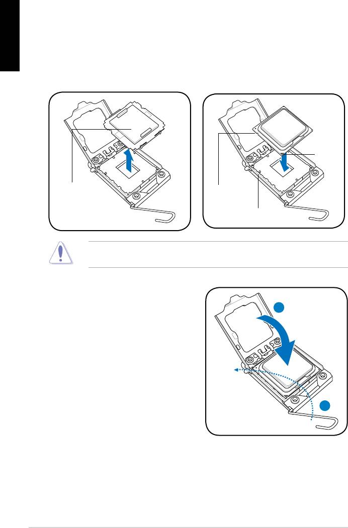
3. Soulevez la plaque avec votre pouce et votre index à un angle de 100º, puis
enlevez le couvercle PnP de la plaque.
4. Placez le CPU sur le socket, en vous assurant que la marque en forme de
triangle doré est placée en bas à gauche du socket. Les ergots d’alignement
du socket doivent correspondre aux encoches du CPU.
5. Refermez la plaque, puis pressez le levier jusqu’à ce qu’il se loge dans le
loquet de rétention.
• Pour éviter d’endommager les broches du socket, ne retirez le couvercle
PnP que lors de l’installation d’un CPU.
• Veuillez garder le couvercle en cas de retour du produit.
• La garantie de ce produit ne couvre pas les dommages causés aux broches
du socket.
.
Mémoire Système
Vous pouvez installer des DIMM DDR2 unbuffered non-ECC de 512 MO, 1 Go et 2
Go dans les sockets.
• Vous pouvez installer des modules mémoire de tailles variables dans le
Canal A et B. Le système mappe la taille totale du canal de plus petite taille
pour les configurations dual-channel. Tout excédant de mémoire du canal
le plus grand est alors mappé pour fonctionner en single-channel.
• Installez toujours des modules mémoire avec une latence CAS identique.
Pour obtenir une compatibilité optimale, il vous est recommandé de vous
équiper des modules de mémoire auprès du même vendeur.
• En raison des limitations d’adressage mémoire sur les systèmes
d’exploitation Windows 32-bits, lorsque vous installez 4Go ou plus de
mémoire sur cette carte mère, le montant de mémoire utilisable par le
système d’exploitation sera de 3 Go ou moins. Pour une utilisation effective
de la mémoire, vous pouvez :
—
Utiliser un maximum de 3 Go lors de l’utilisation d’un système
d’exploitation 32-bits.
—
Installer un système d’exploitation Windows 64-bits si vous souhaitez
installer 4 Go ou plus de mémoire sur cette carte mère.
• Cette carte mère ne supporte pas les modules mémoire composés de
puces mémoire de 256 Mo ou moins.
Canal
Emplacements
Canal
A
DIMM_A1
Canal
B
DIMM_B1

Informations du bios, Informations sur le cd de support, Français
Страница 4
- Изображение
- Текст
4
Français
ASUS P5KPL-AM EPU
4.
Informations du BIOS
Utilisez le programme de configuration du BIOS pour mettre à jour le BIOS ou
configurer ses paramètres. Les écrans BIOS comprennent les clés de navigation
et une courte aide en ligne pour vous guider. Si vous rencontrez des problèmes
liés au système ou si le système devient instable une fois que vous aurez modifié
les paramètres, chargez les Paramètres de Réglage Par Défaut. Rendez visite au
site web d’ASUS (www.asus.com) pour obtenir les mises à jour.
Pour accéder au Setup lors du démarrage:
Pressez <Suppr> lors du Test Automatique de Démarrage (POST : Power-On
Self Test ). Si vous ne pressez pas la touche <Suppr>, le POST continuera son
programme de test.
Pour accéder au programme de configuration du BIOS après le POST :
• Redémarrez le système en pressant <Ctrl> + <Alt> + <Suppr>, puis pressez
<Suppr> lors du POST, ou
• Pressez le bouton de réinitialisation situé sur le châssis puis pressez <Suppr>
lors du POST, ou
• Eteignez et rallumez le système puis pressez <Suppr> lors du POST.
Pour mettre à jour le BIOS avec ASUS EZ Flash 2 :
Démarrez le système et appuyez sur <Alt> + <F2> lors du POST pour lancer EZ
Flash 2. Insérez un disque flash USB contenant le dernier fichier image du BIOS.
EZ Flash 2 lance le processus de mise à jour du BIOS et redémarre le système
automatiquement une fois terminé.
Pour restaurer le BIOS avec CrashFree BIOS :
Démarrez le système. Si le BIOS est corrompu, l’outil de restauration automatique CrashFree
BIOS 3 vérifiera la présence du fichier du BIOS sur le lecteur optique et le disque flash
USB. Connectez un disque flash USB ou insérez le CD de support dans le lecteur optique
contenant le dernier fichier image du BIOS ou celui d’origine. Redémarrez le système une
fois le processus de restauration du BIOS terminé.
5.
Informations sur le CD de support
Cette carte mère supporte les systèmes d’exploitation Windows
®
XP / Vista. Installez
toujours la dernière version d’OS et les mises à jour correspondantes de manière à profiter
pleinement des caractéristiques de votre matériel.
Le CD de support livré avec la carte mère contient les pilotes, les applications logicielles, et
les utilitaires que vous pouvez installer pour tirer partie de toutes les fonctions de la carte
mère.
Si l’Exécution automatique n’est pas activée sur votre ordinateur, parcourez
le contenu du CD de support pour localiser le fichier ASSETUP.EXE dans le
répertoire BIN. Double-cliquez sur ASSETUP.EXE pour lancer le CD.

5
ASUS P5KPL-AM EPU
Deutsch
1.
Motherboard-Layout
2.
Installieren der CPU
So installieren Sie den Prozessor:
1. Drücken Sie den Arretierhebel mit Ihrem Daumen (A) und schieben Sie ihn nach
links (B), bis er vom Halteriegel losgelassen wird.
Ladehebel
Halteriegel
PnP-Kappe
Diese Seite der Cam-Box
sollte zu Ihnen zeigen.
A
B

ASUS P5KPL-AM EPU
Deutsch
.
Arbeitsspeicher
Sie können 512 MB, 1 GB und 2 GB ungepufferte nicht-ECC DDR2 DIMMs in den
DIMM-Sockeln installieren.
2. Heben Sie den Arretierhebel bis zu einem Winkel von 135º hoch.
3. Heben Sie die Deckplatte mit Daumen und Zeigefinger bis zu einem Winkel von
100º hoch, und drücken Sie die PnP-Abdeckung von der Deckplattenaussparung,
um sie zu entfernen.
4. Legen Sie die CPU auf den Sockel. Richten Sie dabei das goldene Dreieck auf
die linke untere Kante des Sockels aus. Die Sockelausrichtungsnase muss in
die CPU-Kerbe einpassen.
5. Schließen Sie die Deckplatte und drücken Sie dann den Arretierhebel, bis er in
den Halteriegel einrastet.
• Um Schäden an den Sockelpolen zu vermeiden, entfernen Sie bitte die PnP-
Abdeckung nicht vor dem Beginn der CPU-Installation.
• Bitte bewahren Sie die Abdeckung für den Fall einer Rückgabe des Produktes
auf.
• Die Produktgarantie deckt keine Beschädigung der Sockelpole ab.
• Sie können verschiedene Speichergrößen in Channel A und Channel B
installieren. Das System ordnet die gesamte Größe des weniger belegten
Kanals für die Dual-Channel-Konfiguration zu. Der überschüssige Speicher
des höher belegten Kanals wird dann der Single-Channel-Konfiguration
zugeordnet.
• Installieren Sie immer DIMMs mit gleicher CAS-Latenzzeit. Für optimale
Kompatibilität wird empfohlen, nur Speichermodule eines Herstellers zu
verwenden.
• Durch die Speicheradressenbeschränkung in 32-Bit-Windows
®
können vom
Betriebssystem nur 3GB oder weniger benutzt werden, selbst wenn 4GB
installiert wurden. Für eine effektive Speichernutzung empfehlen wir Ihnen
folgendes:
— Installieren Sie maximal 3GB Speicher, wenn Sie ein 32-Bit-Windows
®
—
betriebssystem benutzen.
— Installieren Sie ein 64-Bit-Windows
®
-betriebssystem, wenn Sie auf dem
Motherboard 4GB oder mehr Speicher installieren wollen.
• Dieses Motherboard unterstützt keine DIMMs, die aus 256 Megabit- (Mb)
Chips oder weniger hergestellt wurden.
Kanal
Steckplätze
Kanal A
DIMM_A1
Kanal B
DIMM_B1

7
ASUS P5KPL-AM EPU
Deutsch
4.
BIOS-Informationen
Benutzen Sie das BIOS-Einstellungsprogramm zum aktualisieren des BIOS oder
zur Konfiguration seiner Parameter. Die BIOS-Anzeigen enthalten Navigations-
anleitungen und eine kurze Online-Hilfe, um Ihnen die Verwendung zu erleichtern.
Falls in Ihrem System Probleme auftauchen, oder das System nach dem Verändern
einiger Einstellungen instabil wird, sollten Sie die Standardeinstellungen zurückholen.
Weitere Neuigkeiten finden Sie auf der ASUS-Webseite (www.asus.com).
So öffnen Sie das BIOS-Setup beim Systemstart:
Drücken Sie <Entf> während des Power-On Self-Test (POST). Wenn Sie nicht <Entf>
drücken, fährt der POST mit seiner Routine fort.
So öffnen Sie das Setup nach dem POST:
• Starten Sie das System neu, indem Sie <Strg> + <Alt> + <Entf> drücken, und
drücken Sie dann <Entf> während des POST, oder
• Drücken Sie den Reset-Schalter am Computergehäuse, und drücken Sie dann
<Entf> während des POST, oder
• Schalten Sie das System aus und wieder an, und drücken Sie dann <Entf>
während des POST
Aktualisieren des BIOS mit ASUS EZ Flash 2:
Booten Sie das System neu und drücken <Alt> + <F2> während des POST, um
EZ Flash 2 zu starten. Legen Sie die Diskette, die die neueste BIOS-Datei enthält,
ein. EZ Flash 2 führt den BIOS-Aktualisierungsprozess aus und startet das System
automatisch nach dem Vervollständigen des Prozesses neu.
So stellen Sie das BIOS mit CrashFree BIOS wieder her:
Starten Sie das System. Falls die BIOS-Datei beschädigt ist, sucht das CrashFree
BIOS 3-Wiederherstellungsprogramm nach einer Diskette oder CD, mit der das BIOS
wieder hergestellt werden kann. Legen Sie die Support-CD des Motherboards, oder
eine Diskette mit der ursprünglichen oder einer neueren BIOS-Datei ein. Starten Sie
das System neu, wenn das BIOS wieder hergestellt ist.
5.
Software-Unterstützungbg
Das Motherboard unterstützt Windows
®
XP/Vista Betriebssysteme (OS). Installieren
Sie bitte immer die neueste OS-Version und die entsprechenden Updates, um die
Funktionen Ihrer Hardware zu maximieren.
Die mit dem Motherboard gelieferte Support-CD enthält die Treiber, Anwendungs-
Software und Programme die Sie installieren können, um alle Motherboard-
Funktionen benutzen zu können. Es wird bei aktivierter Autorun-Funktion
automatisch das Treibermenü angezeigt.
Wenn Autorun nicht aktiviert ist, durchsuchen Sie den Inhalt der Support-CD,
um die Datei ASSETUP.EXE im Ordner BIN zu finden. Doppelklicken Sie auf
das Dateisymbol ASSETUP.EXE, um die CD auszuführen.

ASUS P5KPL-AM EPU
Italiano
1.
Diagramma disposizione scheda madre
2.
Installazione della CPU
Installazione della CPU:
1. Premere la levetta di carico con il pollice (A), poi spostarla e sinistra (B) finché
è liberata dalla linguetta di trattenimento.
Levetta di carico
Linguetta di trattenimento
Copertura PnP
Questo lato del modulo deve essere
rivolto verso sé stessi.
A
B

ASUS P5KPL-AM EPU
Italiano
3.
Memoria di sistema
Nelle prese per DIMM, si possono installare moduli di memoria DIMM DDR non-ECC,
senza buffer, da 512 MB, 1 GB e da 2 GB.
2. Sollevare la levetta di carico nella direzione indicata dalla freccia ad un anglo
di 135°.
3. Sollevare la placca di carico con il pollice e l’indice ad un angolo di 100º (A),
poi spingere la copertura PnP dalla placca di carico per rimuoverla (B).
4. Collocare la CPU sopra la presa, assicurandosi che il triangolo dorato si trovi
nell’angolo in basso a sinistra della presa. Il tasto di allineamento della presa
deve adattarsi alla dentellatura della CPU.
5. Chiudere la placca di carico (A), poi spingere la leva di carico (B) finché scatta
nella linguetta di trattenimento.
•
Per evitare di danneggiare i pin, non rimuovere la copertura PnP salvo
si stia installando una CPU.
•
Conservare il cappuccio per eventuali restituzioni del prodotto.
•
La garanzia del prodotto non copre i danni ai pin della presa.
• È possibile installare diversi formati di memoria nei canali A e B. Il sistema
mappa la dimensione totale del canale di dimensione più piccolo per la
configurazione a canale doppio. Qualsiasi accesso alla memoria dal canale
di dimensione maggiore, viene quindi mappato per il funzionamento a canale
singolo.
• Utilizzare e installare sempre moduli DIMM con la stessa latenza CAS. Per
poter garantire la perfetta compatibilità dei moduli, si raccomanda di utilizzare
moduli di memoria acquistati presso lo stesso venditore.
• A causa dei limiti con gli indirizzi di memoria nel sistema operativo Windows®
a 32 bit, quando si installa una memoria da 4GB o più sulla scheda madre, la
memoria effettivamente utilizzabile dal sistema operativa può essere di 3GB
o meno. Per usare in modo efficace la memoria, si raccomanda di eseguire
una delle seguenti azioni:
— Usare 3GB di memoria di sistema al massimo se si utilizza il sistema
operativo Windows® a 32 bit.
— Per installare 4GB di memoria o più sulla scheda madre, installare il
sistema operativo Windows® a 64 bit.
• Questa scheda madre non supporta DIMM da 256 megabit (Mb) o minori.
Canale doppio
Prese
Coppia A
DIMM_A1
Coppia B
DIMM_B1

Informazioni sul bios, Supporto per il software, Italiano
Страница 10
- Изображение
- Текст
10
ASUS P5KPL-AM EPU
Italiano
4.
Informazioni sul BIOS
Usare l’utilità per la configurazione del BIOS per aggiornare il BIOS o configurarne i
parametri. La schermata BIOS include tasti di navigazione ed una concisa guida in
linea. Se si riscontrano problemi con il sistema, oppure se questo diventa instabile
dopo avere modificato le impostazioni, caricare le impostazioni predefinite di
configurazione Setup Defaults. Visitare la pagina Web ASUS (www.asus.com) per
gli aggiornamenti.
Per accedere al Setup all’avvio:
Premere il tasto <Delete> durante il POST (Power On Self Test). Se non si preme il
tasto <Delete>, il POST continua le sue routine di diagnostica.
Per accedere al Setup dopo il POST:
• Riavviare il sistema premendo i tasti <Ctrl> + <Alt> + <Delete>, poi premere il
tasto <Delete> durante il POST, oppure
• Premere il tasto di ripristino sul telaio, poi premere il tasto <Delete> durante il
POST, oppure
• Spegnere e riaccendere il sistema e poi premere il tasto <Delete> durante il
POST
Aggiornare il BIOS con ASUS EZ Flash 2:
Avviare il sistema e premere <Alt> + <F2> nel corso del POST per lanciare EZ Flash 2.
Inserire una memoria flash USB contenente il file con la versione più recente del BIOS.
EZ Flash 2 esegue il processo di aggiornamento del BIOS e riavvia automaticamente
il sistema una volta completato.
Ripristinare il BIOS con CrashFree BIOS :
Avviare il sistema. Se il BIOS è danneggiato, lo strumento per il ripristino automatico
CrashFree BIOS 3 verifica l’unità ottica e la memoria flash USB per verificare la
presenza di un file BIOS in modo da poter procedere al ripristino del BIOS: Inserire
una memoria flash USB o il CD di supporto che contiene il file con la versione più
recente o originale del BIOS. Riavviare il sistema dopo avere eseguito il ripristino
del BIOS.
5.
Supporto per il software
Questa scheda madre supporta un sistema operativo (OS) Windows
®
XP/Vista.
Installate sempre l’ultima versione OS e gli aggiornamenti corrispondenti, in modo
da massimizzare le funzioni del vostro hardware.
Il CD di supporto fornito con il pacchetto della scheda madre contiene i driver, le
applicazioni software e le utilità che possono essere installate per poter sfruttare tutte
le caratteristiche della scheda madre. Viene visualizzato automaticamente il menu
Driver se sul computer è attiva l’Esecuzione automatica.
Se sul computer non è attiva ESECUZIONE AUTOMATICA, sfogliare i contenuti
del CD di supporto per individuare il file ASSETUP.EXE nella cartella BIN. Fare
doppio clic su ASSETUP.EXE per eseguire il CD.

Комментарии

Index
1. English ………………………………………………………………………1
2. Türkçe ……………………………………………………………………..41
3.
…………………………………………………………………..
81
4. …………………………………………………………………….121
…………………………………………………………………..161
6. Bahasa Indonesia ……………………………………………………
201
7. Italiano
……………………………………………………………………241
8.
한국어
……………………………………………………………………
281
9. Polski ……………………………………………………………………..321
10. Português ……………………………………………………………….361
………………………………………………………………….401
12.
……………………………………………………………………
441
13. Srpski …………………………………………………………………….481
14. Español ………………………………………………………………….521
15.
ไทย
………………………………………………………………………..
561
……………………………………………………………….
601
17. ……………………………………………………………………..641
18. ……………………………………………………………………..681

Motherboard
installation guide
Motherboard
E4204
September 2008
Copyright © 2008 ASUSTeK COMPUTER INC. All Rights Reserved.
permission of ASUSTeK COMPUTER INC. (“ASUS”).
product is defaced or missing.
Safety information
Electrical safety
•
•
power cables for the devices are unplugged before the signal cables are
•
Before connecting or removing signal cables from the motherboard, ensure
that all power cables are unplugged.
•
Seek professional assistance before using an adpater or extension cord.
These devices could interrupt the grounding circuit.
•
•
Operation safety
•
the manuals that came with the package.
•
•
•
•
Place the product on a stable surface.
•
English
Chapter 1: Quick Start
1.1 Installing the CPU
1.1.1 Intel LGA775 Socket
2. Release the load lever from the
motherboard.
retention tab and lift the load plate.
Then push the PnP cap from the
load plate window to remove
To prevent damage to the socket
pins, do not remove the PnP cap
Pick and Place Cap (PnP Cap)
4. Make sure that the gold triangle
3. Position the CPU over the socket.
is on the bottom‑left corner of the
socket.
4
English
6. Close the load plate, then push the load lever until it snaps into the retention
tab.
CPU into the socket to prevent
bending the connectors on the
socket and damaging the CPU!
1.1.2 Intel LGA1366 Socket
Retention tab
motherboard.
A
thumb (A), then move it to the left
(B) until it is released from the
retention tab.
B
Load lever
To prevent damage to the socket
pins, do not remove the PnP cap
Load plate
the arrow to a 135º angle.
4
3
ASUS Motherboard installation guide 5
English
5. Remove the PnP cap from the CPU
6. Position the CPU over the socket,
socket.
making sure that the gold triangle
is on the bottom‑left corner of the
Gold
triangle
mark
PnP cap
CPU notch
Alignment key
socket to prevent bending the connectors on the socket and damaging the CPU!
8. Close the load plate (A), and then
push the load lever (B) until it snaps
A
into the retention tab.
B
6
1.1.3 AMD AM2 Socket
English
motherboard.
the socket, then lift it up to a 90º
angle.
Make sure that the socket lever is lifted up to 90º angle. Otherwise, the CPU will
3. Position the CPU above the socket
such that the CPU corner with the
down the socket lever to secure the
gold triangle matches the socket
CPU. The lever clicks on the side tab
corner with a small triangle.
to indicate that it is locked.
socket to prevent bending the connectors on the socket and damaging the CPU!
ASUS Motherboard installation guide 7
English
1.2 Installing the heatsink and fan
For Intel-certied heatsink:
2. Some heatsinks will come with
pre‑applied thermal paste. If so,
do not scrape it off and remove
installation. If not, before installing
thermal paste to the exposed area
of the CPU that the heatsink will be
in contact with. Make sure that it is
3. Orient each fastener with the
narrow end of the groove pointing
outward.
8
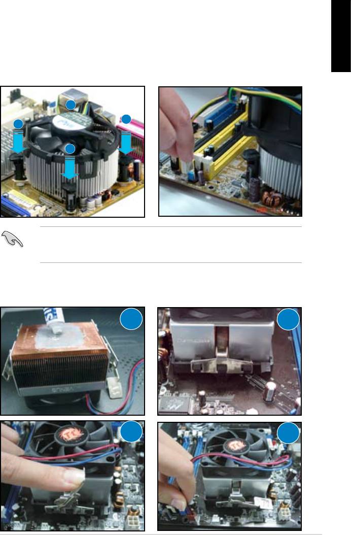
4. Push down two fasteners at a time
5. Connect the CPU fan cable to the
in a diagonal sequence to secure
corresponding connector on the
English
motherboard.
place.
B
A
A
B
directional heatsink to gain the maximum heat dissipation area.
For AMD-certied heatsink:
1
2
3
4
ASUS Motherboard installation guide 9
English
1.3 Installing a DIMM
motherboard and the components.
2
DDR2 DIMM notch
3
1. Press the retaining clips outward
1
matches the break on the socket.
1
socket until the retaining clips
Unlocked retaining clip
motherboard package.
1.4 Installing the motherboard
1. I/O ports differ with motherboards.
Use and install the rear I/O shield
that comes with the motherboard
Some sharp edges and points
puncture resistant gloves before
motherboard and I/O shield
installation.
10
2. Install the standoffs to the matched
screw holes on the metal plate.
damage the I/O ports. Be cautious
English
when installing the I/O shield.
4. Position the I/O side of the
motherboard toward the rear of the
After all the screws have been
chassis and place the motherboard
inserted, drive the screws until
into the chassis.
of the chassis before installing the motherboard. For some chassis models,
ASUS Motherboard installation guide 11
1.5 Installing the power supply unit
English
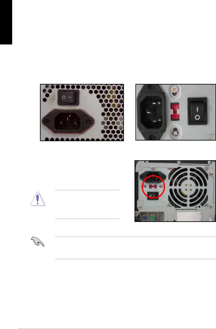
Power Factor Correction (PFC) and the other with passive PFC.
Power supply with active PFC:
Power supply with passive PFC:
Passive PFC requires user to
the AC input voltage.
voltage.
area.
12
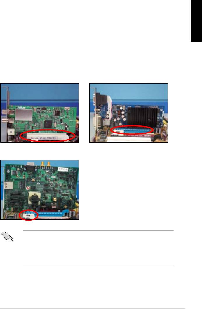
1.6 Installing an expansion card
English
wish to install an expansion card.
3. Screw to secure the card on the slot.
4. Repeat the previous steps to install another expansion card.
PCI card PCIE x16 card
PCIE x1 card
after installing the expansion card.
• Refer to the motherboard user guide for the instructions of the expansion
card signal cable connection.
ASUS Motherboard installation guide 13
1.7 Installing disk drives
English
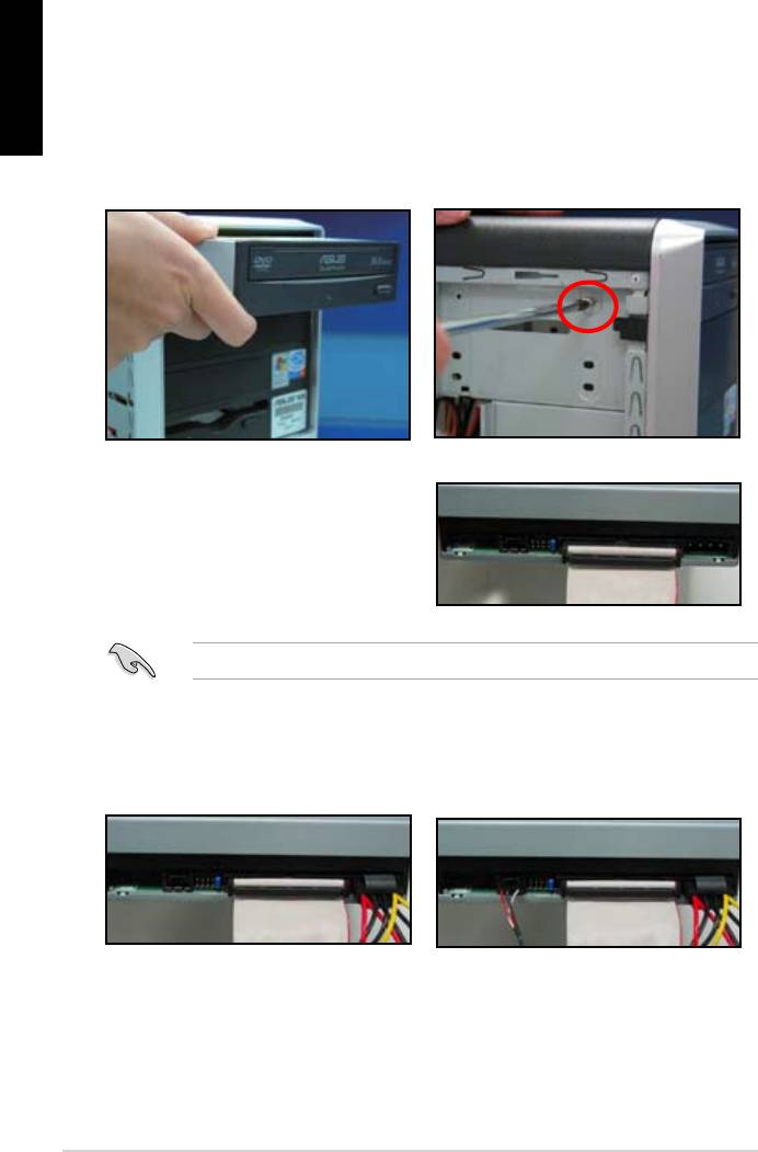
1.7.1 PATA optical disk drive
2. Align with the screw holes and
slide the optical disk drive into the
secure the disk drive with screws.
the optical drive. The red stripe on
should match the dimple marking
Pin1 on the optical drive.
4. Connect the 4‑pin power cable to
5. Attach the audio cable to the
the optical drive.
connector on the optical drive.
14
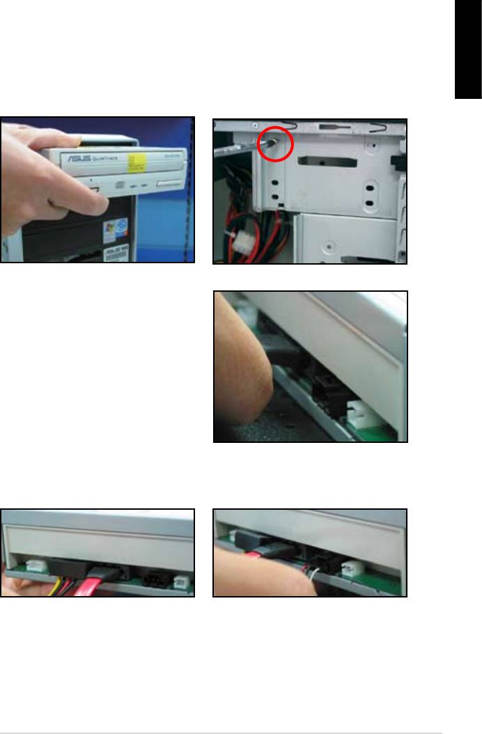
1.7.2 SATA optical disk drive
2. Align with the screw holes and
English
slide the optical disk drive into the
secure the disk drive with screws.
3. Orient and plug the SATA cable into
the optical drive. SATA cables are
cable into the connector.
4. Connect the SATA power cable to
5. Attach the audio cable to the
the the optical drive.
connector on the optical drive.
ASUS Motherboard installation guide 15
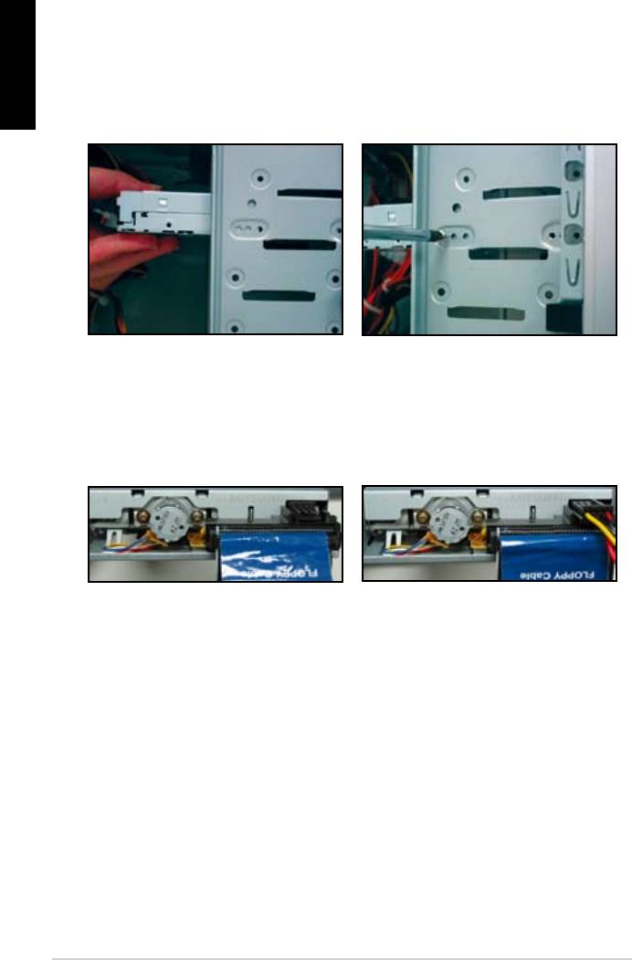
English
1.7.3 Floppy disk drive
2. Align with the screw holes and
secure the disk drive with screws.
the connector at the back of the
red stripe on the cable is the pin1
end and should match pin1 on the
16
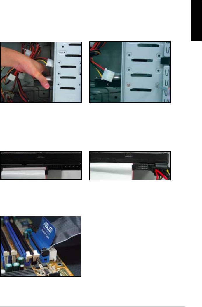
1.7.4 PATA hard disk drive
1. Insert the PATA hard disk drive into
2. Align with the screw holes and
English
secure the disk drive with screws.
3. Orient and connect the signal cable
4. Connect the 4‑pin power cable to
to the hard disk drive. The red stripe
the connector at the back of the
on the cable is the pin1 end. Match
hard disk drive.
force the cable into the connector.
5. Attach the other end of the signal
cable to the corresponding slot on
the motherboard.
ASUS Motherboard installation guide 17
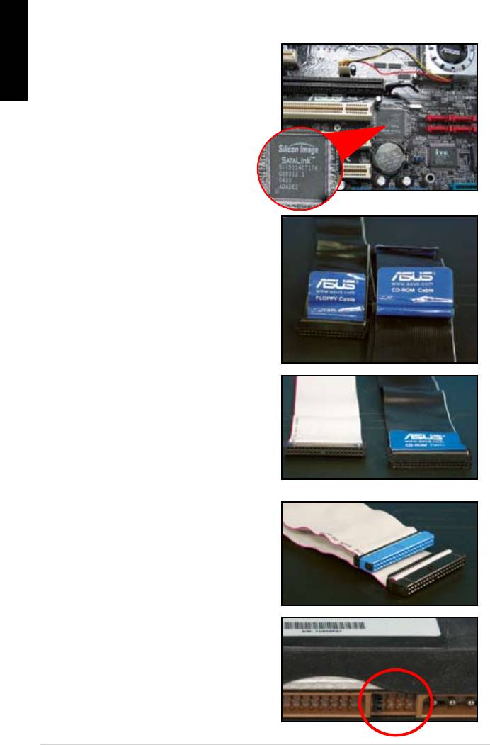
Notes for installing PATA hard disk drive
English
have to install the controller driver
• The cables are designed with pull
drives based on the cable labels.
To prevent damaging the pins, pull
the cable tabs to disconnect the
cable.
disk drives, the newer 80‑wire
(right) and the older 40‑wire (left)
cables. For ATA66/100/133 disk
offer a better performance. The
optical drives.
• The cable connector is color‑
coded. The blue one is for the host
drive.
different position, one in master
18
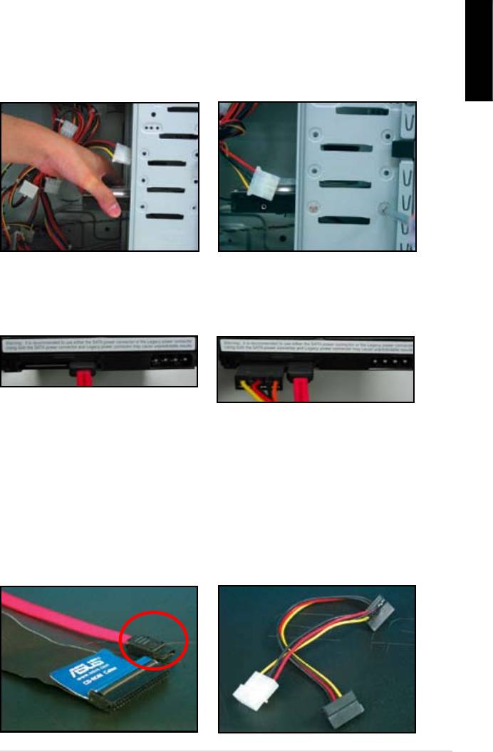
1.7.5 SATA hard disk drive
1. Insert the SATA hard disk drive into
2. Align with the screw holes and
English
secure the disk drive with screws.
3. Orient and connect the SATA cable
4. Connect the SATA power cable to
to the hard disk drive. The cable can
the connector at the back of the
hard disk drive.
Notes for installing SATA hard disk drive
• Serial ATA (SATA) interface
• The SATA power cable connector
provides higher data transmission
is different from the traditional
speed, and better voltage tolerance.
4‑pin power connector. ASUS
The narrow design of the SATA
motherboard bundles power adapter
cable also solves cabling issues
chassis.
new connector.
ASUS Motherboard installation guide 19
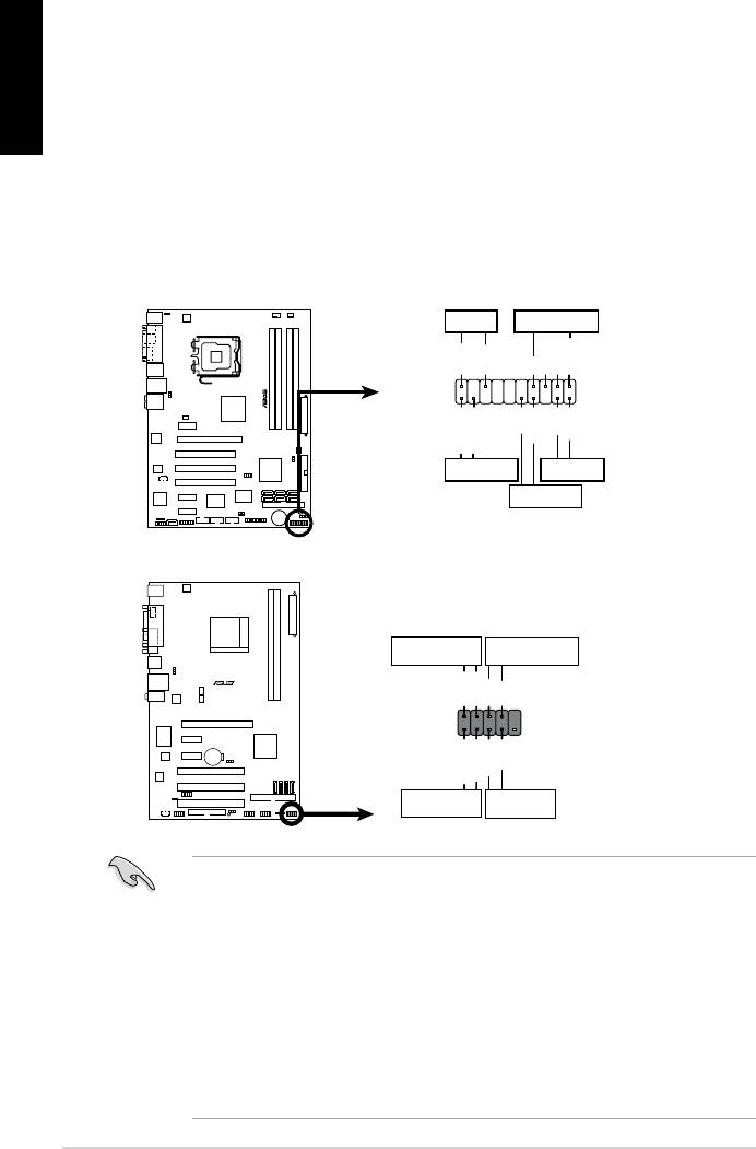
1.8 Front panel cables
English
• RESET (Reset Switch)
• SPEAKER (Speaker Connector)
20
M2N-X
Reset
ANE
RESET
PLED SPEAKER
P5B-E
PLED+
PLED-
+5V
Ground
Ground
Speaker
®
PANEL
PWR
Reset
Ground
Ground
IDE_LED+
IDE_LED-
IDE_LED
RESET
PWRSW
*
Requires an ATX power supply.
20-8 pin front panel connector
PIN1
PIN1
10-1 pin front panel connector
Connect these connectors to the motherboard according to the label.
for the ground pins and the color‑coded wire for the signal pins.
to the connector PIN1 on the motherboard.
user guide for more information.
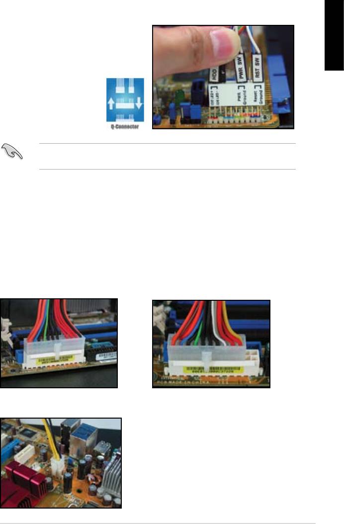
ASUS Q-Connector
English
user guide for details.
details.
1.9 Connecting the ATX power
connector on the motherboard.
20-pin power connector
24-pin power connector
(on the 24-pin female counterpart)
4-pin power connector
ASUS Motherboard installation guide 21
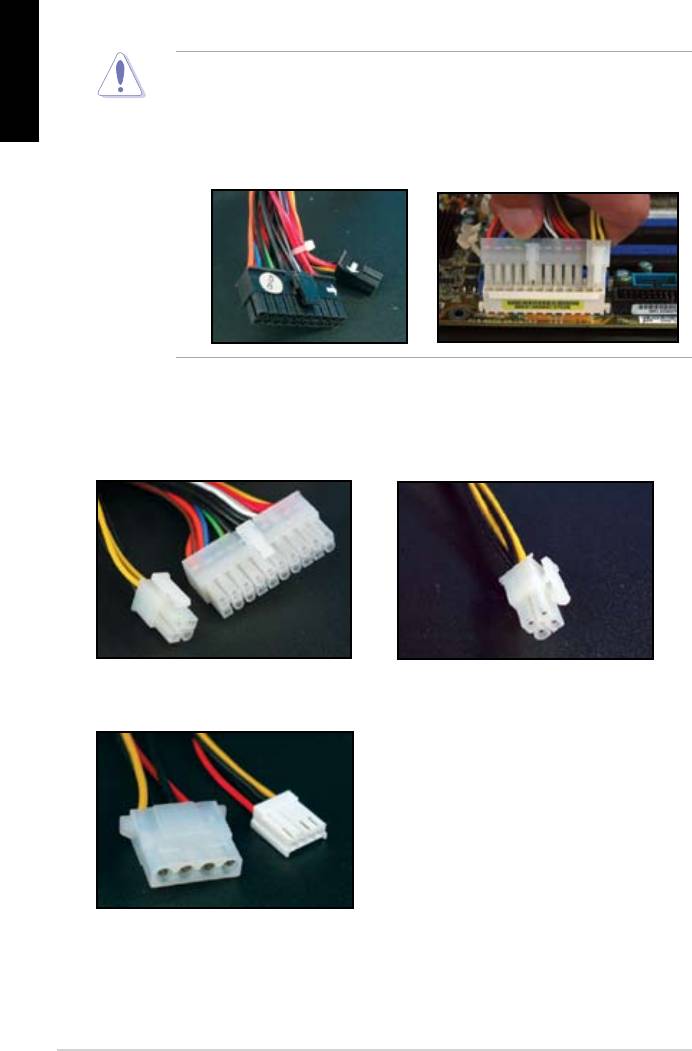
English
connectors to the motherboard.
two connectors and install to the 24‑pin connectors on the motherboard.
Power connectors
20+4 (24) pin ATX connector
4-pin ATX connector
peripheral power connector (left)
oppy power connector (right)
22
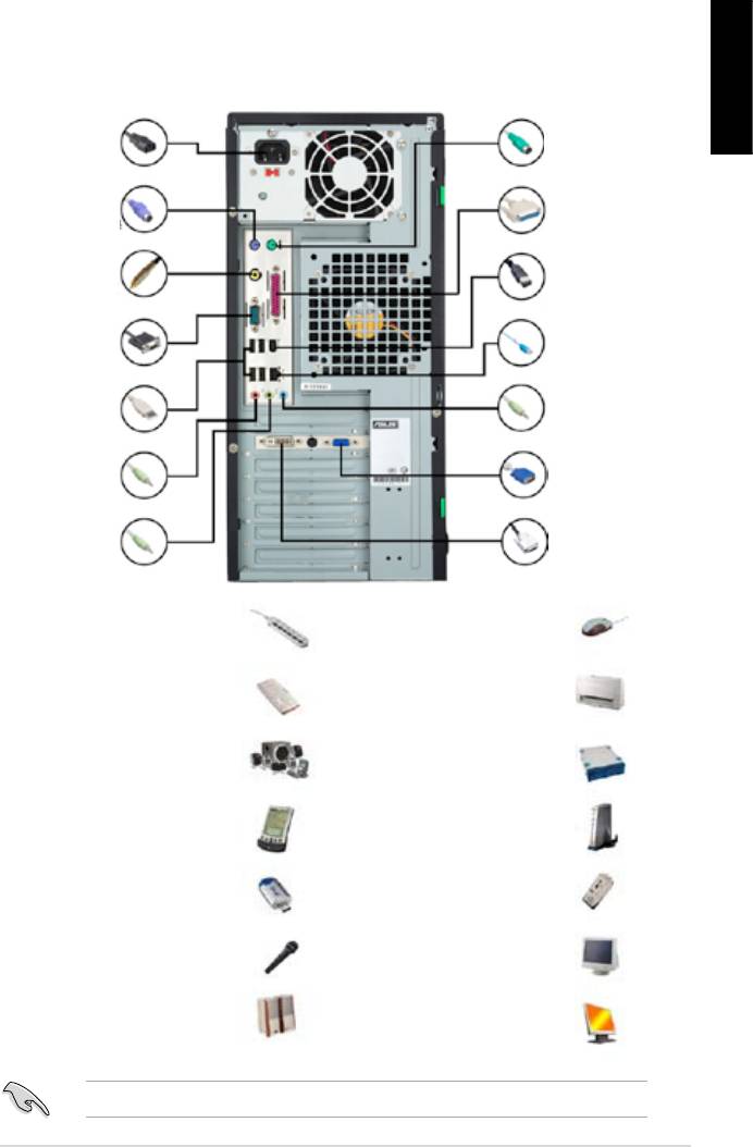
1.10 Peripheral devices and accessories
English
1. AC power plug
8. PS/2
mouse port
2. PS/2 keyboard
9. Parallel port
port
3. S/PDIF out port
10. IEEE1394 port
4. Serial port
11. LAN (RJ45) port
5. USB port
12. Line in port
13. Video graphics
6. Microphone port
adapter port
7. Line out port 14. DVI port
extension cord
mouse
hard disk drive
microphone
ASUS Motherboard installation guide 23
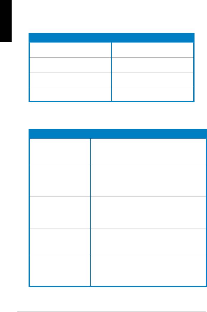
1.11 Startingupforthersttime
English
the BIOS beeps.
BIOS Beep Description
short beeps
short beeps then a pause (repeated)
short beeps
(AMI BIOS)
Four short beeps
Troubleshooting
Trouble Action
• Cannot turn on the computer
working.
The computer is on but the
monitor is black.
• Shut down the computer and remove the power cord.
socket.
a warning message pops on
the screen.)
drive.
• Make sure the device drivers are installed.
24

Chapter 2: Manage/update BIOS
2.1 AFUDOS utility
English
corrupted during the updating process.
Copying the current BIOS
afudos /o[lename]
characters for the extension name.
A:\>afudos /oOLDBIOS1.rom
Main lename Extension name
A:\>afudos /oOLDBIOS1.rom
AMI Firmware Update Utility — Version 1.19(ASUS V2.07(03.11.24BB))
Copyright (C) 2002 American Megatrends, Inc. All rights reserved.
Reading ash ….. done
Write to le…… ok
A:\>
Updating the BIOS le
ASUS Motherboard installation guide 25

English
afudos /i[lename]
disk.
A:\>afudos /iP5K3D.ROM
A:\>afudos /iP5K3D.ROM
AMI Firmware Update Utility — Version 1.19(ASUS V2.07(03.11.24BB))
Copyright (C) 2002 American Megatrends, Inc. All rights reserved.
WARNING!! Do not turn off power during ash BIOS
Reading le ……. done
Reading ash …… done
Advance Check ……
Erasing ash …… done
Writing ash …… 0x0008CC00 (9%)
A:\>afudos /iP5K3D.ROM
AMI Firmware Update Utility — Version 1.19(ASUS V2.07(03.11.24BB))
Copyright (C) 2002 American Megatrends, Inc. All rights reserved.
WARNING!! Do not turn off power during ash BIOS
Reading le ……. done
Reading ash …… done
Advance Check ……
Erasing ash …… done
Writing ash …… done
Verifying ash …. done
Please restart your computer
A:\>
26 Manage/update BIOS
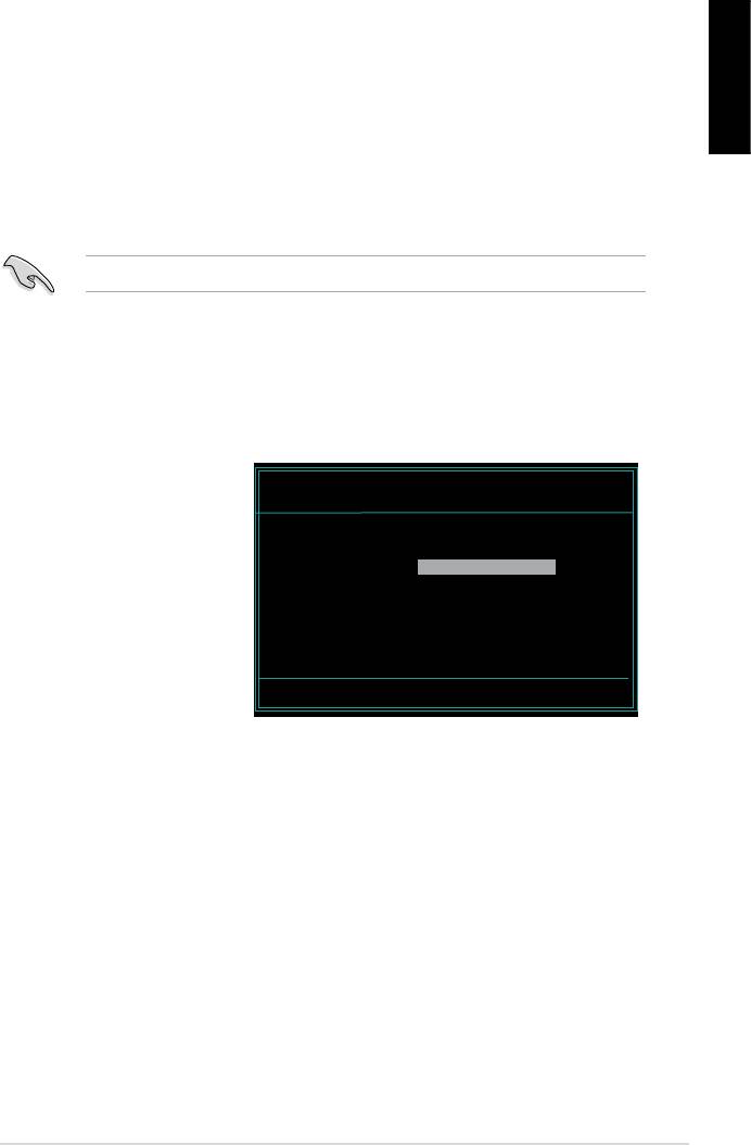
2.2 Award BIOS Flash Utility
Updating the BIOS
English
FAT 16/12 format.
AwardBIOS Flash Utility for ASUS V1.14
(C) Phoenix Technologies Ltd. All Rights Reserved
the name of the disk
For NF590-SLI-M2N32-SLI-DELUXE DATE:03/30/2006
Flash Type — PMC Pm49FL004T LPC/FWH
assignment) to switch to
File Name to Program:
Message: Please input File Name!
<Enter>. The Award BIOS
ASUS Motherboard installation guide 27
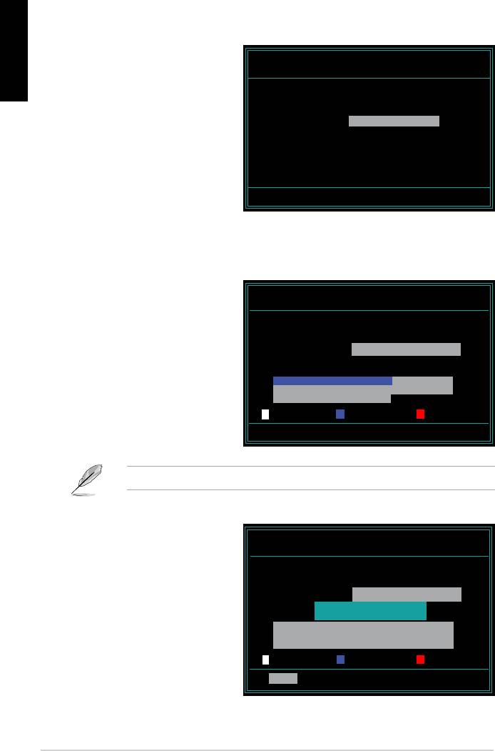
English
AwardBIOS Flash Utility for ASUS V1.14
the File Name to Program
(C) Phoenix Technologies Ltd. All Rights Reserved
For NF590-SLI-M2N32-SLI-DELUXE DATE:03/30/2006
Flash Type — PMC Pm49FL004T LPC/FWH
File Name to Program: M2N32SLI.bin
Message: Do You Want To Save Bios (Y/N)
following screen appears.
AwardBIOS Flash Utility for ASUS V1.14
(C) Phoenix Technologies Ltd. All Rights Reserved
For NF590-SLI-M2N32-SLI-DELUXE DATE:03/30/2006
Flash Type — PMC Pm49FL004T LPC/FWH
File Name to Program: M2N32SLI.bin
Programming Flash Memory — OFE00 OK
Write OK No Update Write Fail
Warning: Don’t Turn Off Power Or Reset System!
AwardBIOS Flash Utility for ASUS V1.14
Flashing Complete
(C) Phoenix Technologies Ltd. All Rights Reserved
message indicating that
For NF590-SLI-M2N32-SLI-DELUXE DATE:03/30/2006
Flash Type — PMC Pm49FL004T LPC/FWH
File Name to Program: M2N32SLI.bin
Flashing Complete
Remove the disk then
Press <F1> to Continue
press <F1> to restart the
Write OK No Update Write Fail
F1
Reset
28 Manage/update BIOS
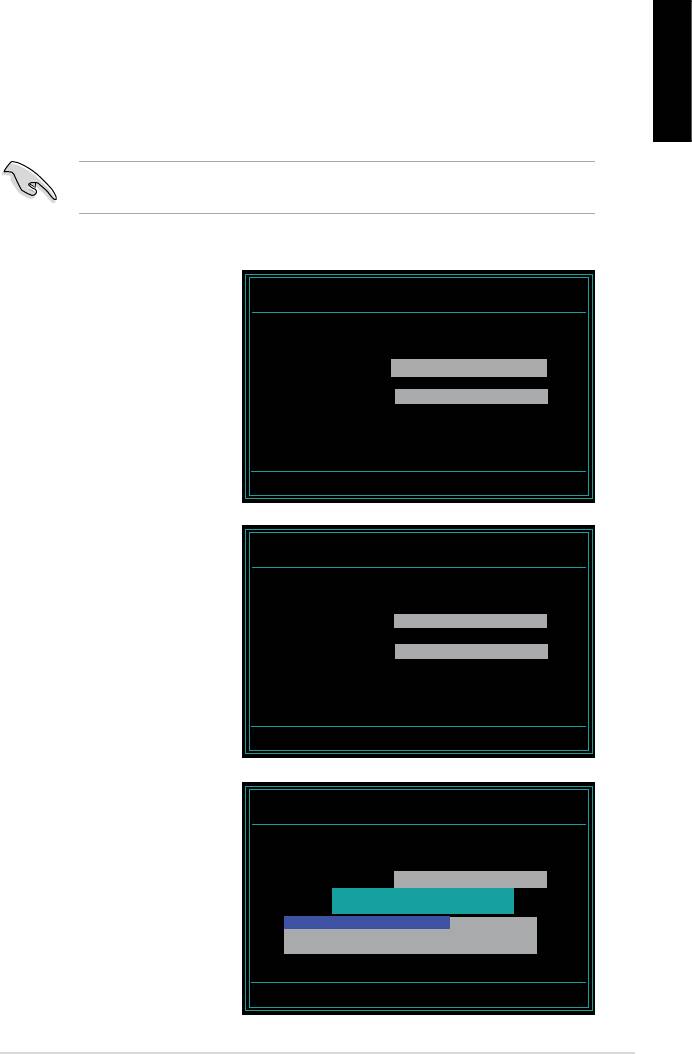
Saving the current BIOS le
English
process.
1. Follow steps 1 to 6 of the
AwardBIOS Flash Utility for ASUS V1.14
(C) Phoenix Technologies Ltd. All Rights Reserved
previous section.
For NF590-SLI-M2N32-SLI-DELUXE DATE:03/30/2006
Flash Type — PMC Pm49FL004T LPC/FWH
File Name to Program: 0112.bin
following screen appears.
Save current BIOS as:
Message:
AwardBIOS Flash Utility for ASUS V1.14
(C) Phoenix Technologies Ltd. All Rights Reserved
For NF590-SLI-M2N32-SLI-DELUXE DATE:03/30/2006
Flash Type — PMC Pm49FL004T LPC/FWH
then press <Enter>.
File Name to Program: 0112.bin
Checksum: 810DH
Save current BIOS as: 0113.bin
Message: Please Wait!
AwardBIOS Flash Utility for ASUS V1.14
(C) Phoenix Technologies Ltd. All Rights Reserved
disk, then returns to the
For NF590-SLI-M2N32-SLI-DELUXE DATE:03/30/2006
Flash Type — PMC Pm49FL004T LPC/FWH
File Name to Program: 0113.bin
Now Backup System BIOS to
File!
Message: Please Wait!
ASUS Motherboard installation guide 29

2.3 ASUS Update utility
English
®
package.
ASUS Update requires an Internet connection either through a network or an
Internet Service Provider (ISP).
Installing ASUS Update
30 Manage/update BIOS
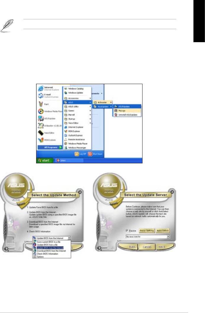
®
English
Updating the BIOS through the Internet
®
desktop, click Start >
Programs > ASUS > ASUSUpdate > ASUSUpdate. The ASUS Update main
window appears.
2. Select Update BIOS from the
3. Select the ASUS FTP site nearest
drop‑down menu list, then click
Next.
click Auto Select. Click Next.
ASUS Motherboard installation guide 31
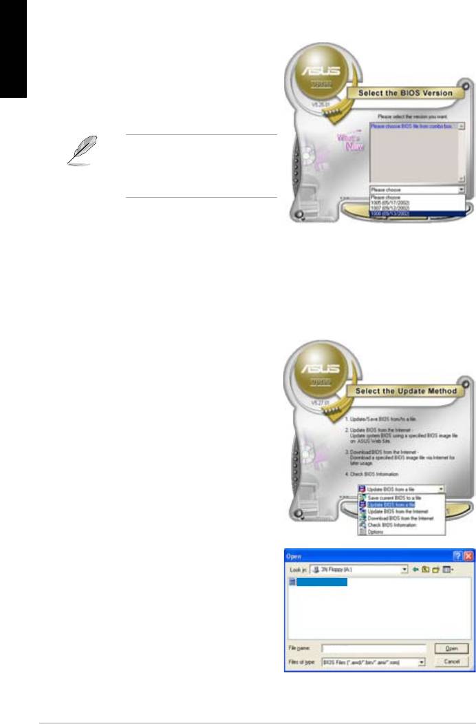
English
4. From the FTP site, select the BIOS
Click Next.
5. Follow the screen instructions to
complete the update process.
capable of updating itself through
Updating the BIOS through a BIOS le
®
desktop, click Start
> Programs > ASUS > ASUSUpdate > ASUSUpdate. The ASUS Update
main window appears.
2. Select
Update BIOS from the
drop‑down menu list, then click Next.
window, then click Open.
P5K3 Deluxe
4. Follow the screen instructions to
complete the update process.
P5K3 Deluxe
32 Manage/update BIOS
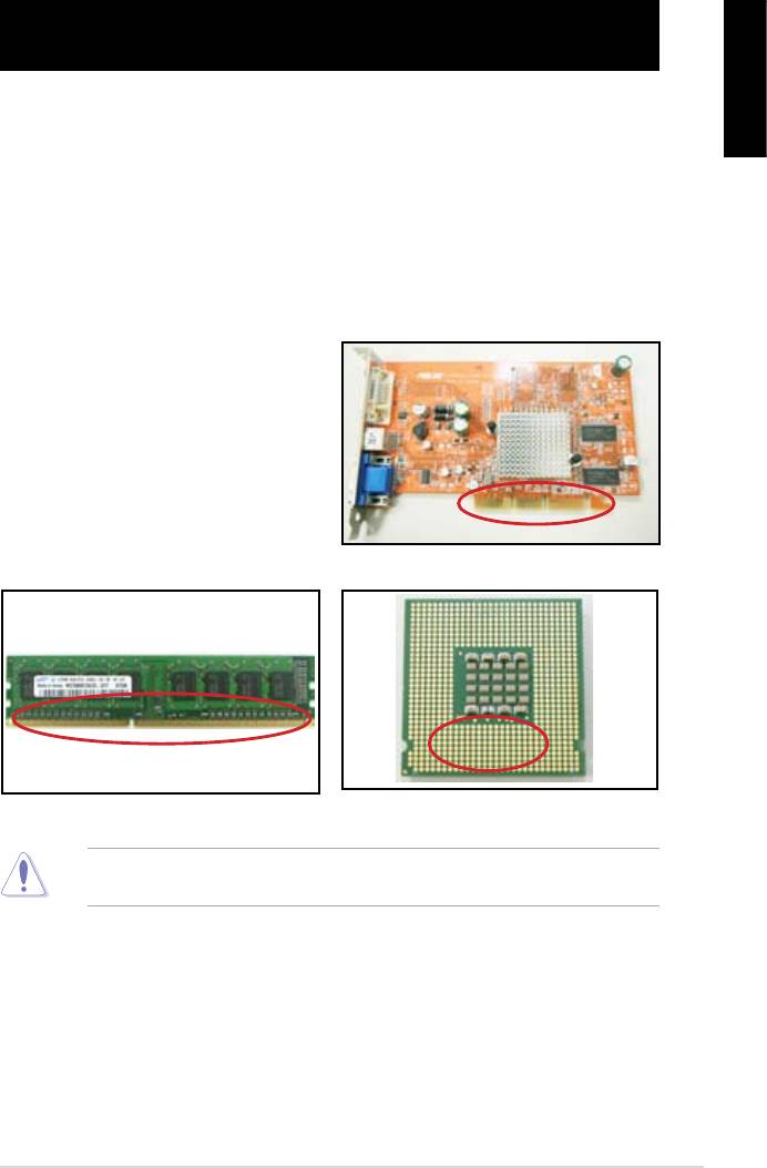
Chapter 3: Troubleshooting
3.1 Troubleshooting for Motherboard DIY
English
3.1.1 Basic troubleshooting
A. Bad connection
1. Make sure there is no contaminants
on the gold contact or the pins.
2. Use a cotton bud or an eraser
crumbs.
VGA card gold contact
DIMM gold contact
LGA775 processor gold contact points
ASUS Motherboard installation guide 33
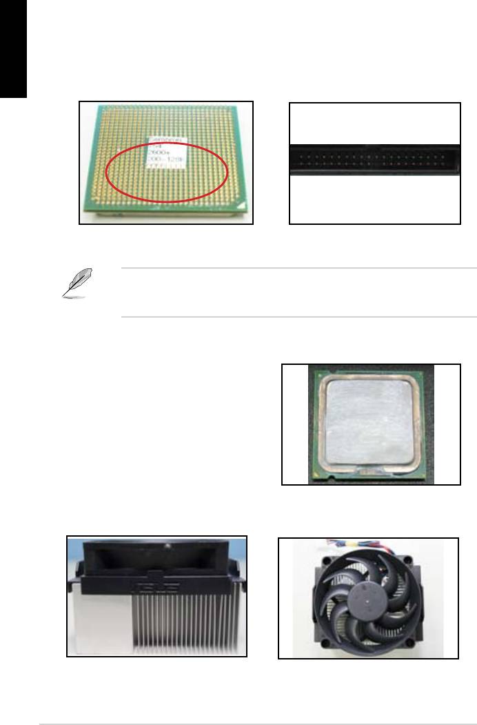
English
CPU pins. A broken and bended pin will cause the component malfunction.
AMD CPU gold pins
Connector pins
B. CPU overheated
thermal paste to the exposed area
of the CPU that the heatsink will be
in contact with. Make sure that it is
CPU surface
2. Make sure there is no contaminants on the heatsink and fan.
Side view of heatsink and fan
Top view of heatsink and fan
3. Follow the instructions of heatsink and fan manufacturers to clean the
contaminants that will slow down the fan rotation.
34 Troubleshooting
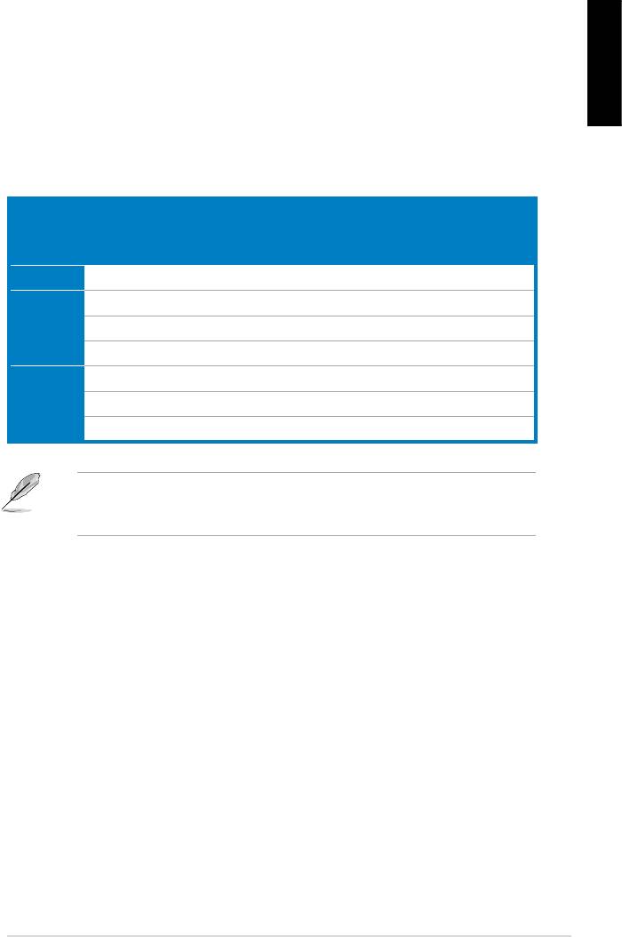
3.2 Other common troubles
unplugged.
English
Test (POST).
• If there are BIOS beeps, refer to section 1.11 for details.
Check Items
Power
Screen
Heatsink
BIOS
Error
Reference
LED
display
and fan
beeps
messages
page
No power Off No Stop No N/A 3‑4
No
On No Stop No N/A 3‑5
screen
On No Running No N/A 3‑5
display
On No Running N//A 3‑5
Failure to
On Running 3‑5
enter OS
On Running No 3‑5
On Running No No 3‑5
team for further help.
ASUS Motherboard installation guide 35
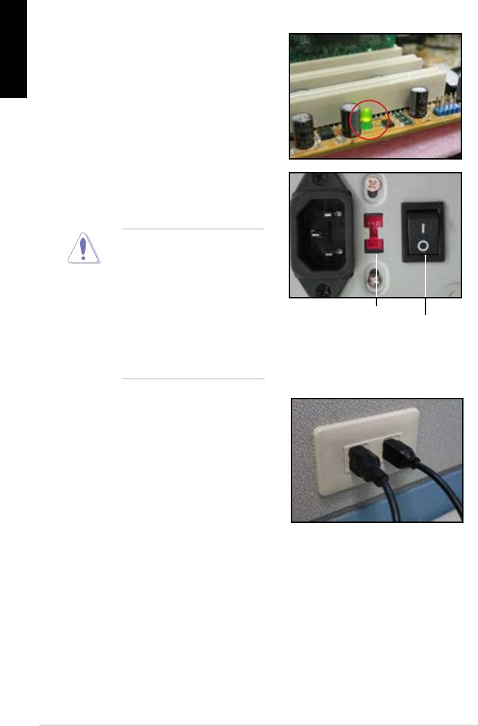
English
3.2.1 No power
the problem.
input voltage, ensure to
disconnect the power
plug. Failure to do so will
AC input voltage switch
Power switch
“—”: On; “O”: Off
power cord to the wall outlet.
• Connect the power plug
NOT connect it to the power
extension, uninterruptible
devices.
• Exchange the power plugs of
check whether the wall outlet is
36 Troubleshooting

3.2.2 Failure to boot-up; No screen display
English
the monitor.
2. Make sure if the problem comes from expansion devices.
3.2.3 Failure to enter the operating system
Contact the device retailer for help.
driver.
the BIOS to load the setup defaults. Refer the motherboard user guide for
details.
ASUS Motherboard installation guide 37

English
using an anti‑virus application.
3.2.4 FAQs
normal.
disk drives.
38 Troubleshooting

Chapter 4: Computer care tips
4.1 Proper care of your PC
English
the computer when it is turned on in case of damage. Internal dust will affect
the operating disk drive and contribute to overheating problem which will cause
computer crash or damage the components.
4.2 Basic knowledge
the ventilation holes. Excessive heat will cause the monitor malfunction.
4. Place the computer on a stable surface.
the best surroundings temperature. Use an air conditioner or a electric fan to
gain a better heat dissipation.
4.3 Usage knowledge
recommended.
cleaning)
• Uninstall the motherboad and hard/optical disk drives, then clean them
with canned air or a soft brush.
static vacuum.
ASUS Motherboard installation guide 39

English
4.4 Tips
40 Computer care tip

Anakart
kurulumkılavuzu
Motherboard

TR4204
Nisan 2008
Telif Hakkı © 2008 ASUSTeK COMPUTER INC. Tüm hakları saklıdır.
Türkçe
Bu el kitabının hiçbir bölümü, onun içinde tanımlanan yazılım ve de ürünler
de dahil olmak üzere, ASUSTeK COMPUTER INC. (“ASUS”) rmasının
açık bir biçimde yazılı izni olmaksızın, satın alan kişi tarafından yedek—
leme amaçlı olarak tutulan dokümantasyon haricinde yeniden üretilemez,
aktarılamaz, kopya edilemez, bir bilgi işlem sistemi içinde depolanamaz, ya
da her hangi bir şekilde ya da hiçbir biçimde hiçbir dile tercüme edilemez.
Aş
ğ
ıdaki şartlarda ürün garantisi ya da hizmeti uzatılmayacaktır: (1) ürünün
ASUS tarafından yazılı bir izin olmaksızın onarılması veya de
ği
ştirilmesi ya
da (2) ürünün seri numarasının tahrif edilmesi ve kaybolmas.
ASUS BU EL KİTABINI, BELİRLİ BİR AMAÇ İÇİN TİCARETE
ELVERİŞLİ NİTELİĞİN YA UYGUNLUĞUN ZIMNİ GARANTİLER
YA DA KOŞULLARI DA DAHİL OLMAK ÜZERE YA DA BUNLARLA
SINIRLI OLMAMAK KAYDIYLAYA AÇIK BİR ŞEKİLDE YA DA ZIM—
NEN HER HANGİ BİR TÜRÜN GARANTİSİ OLMAKSIZIN “OLDUĞU
GİBİ” SAĞLAR. HİÇBİR DURUMDA ASUS, ONUN DİREKTÖRLERİ,
MEMURLARI, ÇALIŞANLARI YA DA ACENTELERİ, BU EL KİTABI
YA DA ÜRÜN İÇERİSNDE HER HANGİ BİR KUSUR YA DA HATADAN
DOĞAN BU TÜR ZARARLARIN MEYDANA GELME OLASILIĞINI
TAVSİYE ETMİŞ OLSA DAHİ, HER HANGİ BİR DOLAYLI, ÖZEL,
TESADÜFİ YA DA SONUÇSAL ZARARLARDAN ( KAR KAYIPLA—
RI, İŞ KAYBI, KULLANIM YA DA VERİ KAYBI, İŞİN KESİNTİYE
UĞRAMASI VE DE BENZERİ GİBİ ZARARLAR DA DAHİL OLMAK
ÜZERE ) ÖTÜRÜ SORUMLU TUTULAMAZ.
BU EL KİTABI İÇİNDE YER ALAN SPESİFİKASYONLAR
VE DE BİLGİ SADECE BİLGİLENDİRME AMAÇLI OLARAK
TEDARİK EDİLMİŞTİR VE DE HER HANGİ BİR BİLDİRİMDE
B U L KUN U L MA K S IN I N H E R H A N Gİ B İR Z AM A N D A
DEĞİŞTİRİLMEYE TABİİDİR, VE DE ASUS TARAFINDAN BİR TAAH—
HÜT ŞEKLİNDE YOURMLANAMAZ. ASUS BU EL KİTABINDA VE
DE ONUN İÇİNDE TANIMLANAN YAZILIM VE DE ÜRÜNLERDE DE
DAHİL OLMAK ÜZERE GÖRÜNEN HER HANGİ BİR HATA YA DA
KUSURLARDAN ÖTÜRÜ HİÇBİR YÜKÜMLÜLÜK YA DA SORUM—
LULUK ÜSTLENMEZ.
Bu el kitabı içinde görünen ürünler ve de kurum isimleri, onların şirketlerinin
tescilli ticari markaları ya da telif hakları olabilir ya da olmayabilir ve de
ihlal amaçlı olmaksızın sadece tanıtım ya da açıklama amaçlı olarak ve de
mal sahibinin yararına kullanılmaktadır.
42

Güvenlik bilgileri
Elektriksel güvenlik
Türkçe
Çalıştırma güvenliği
43
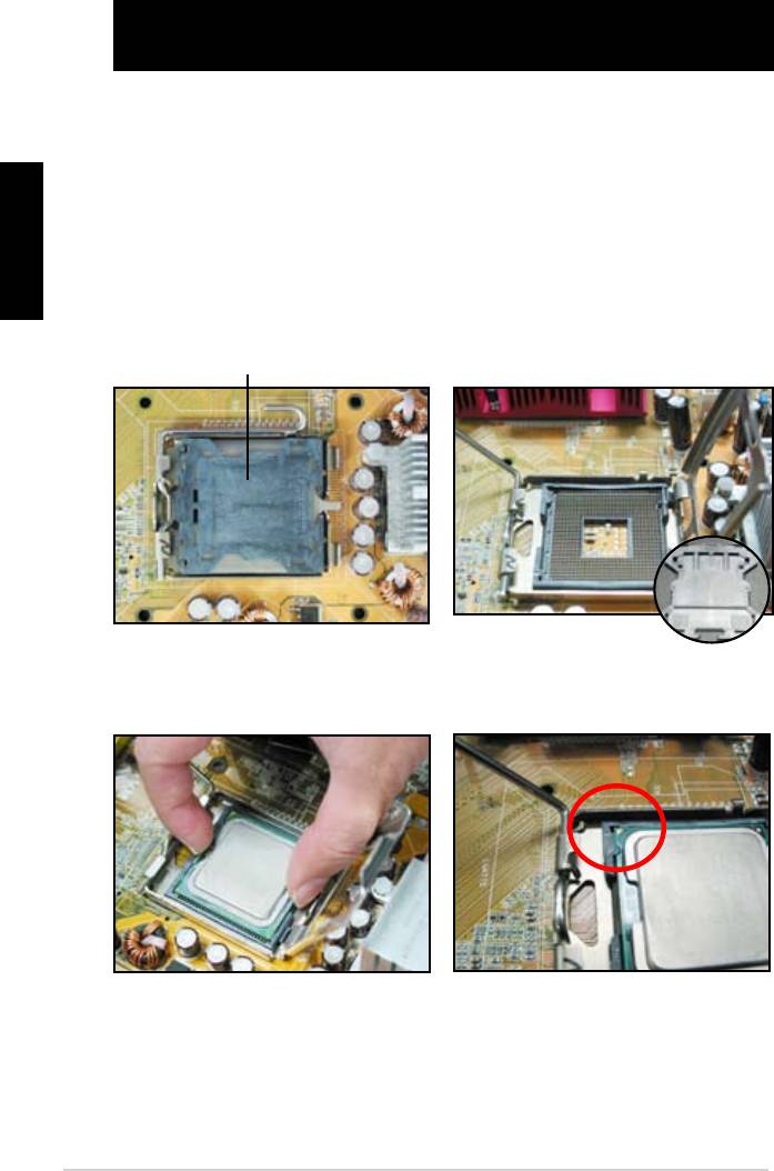
Bölüm 1: Hızlı Çalıştırma
1.1 CPU Montajı
1.1.1 Intel LGA775 Soket
Türkçe
tespit edin.
Soket pinlerine hasar gelmesini
önlemek için CPU kurulumu
Kaldır-Yerleştir Başlığı (PnP Başlığı)
44
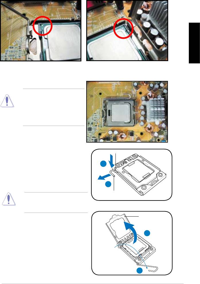
Türkçe
itin.
konektörlerin bükülmesini ve
CPU’nun hasar görmesini
1.1.2 Intel LGA1366 Yuvası
Tutma çıkıntısı
A
B
sola (B) hareket ettirin.
Yük kolu
önlemek için, bir CPU takana
Yük levhası
4
3
45
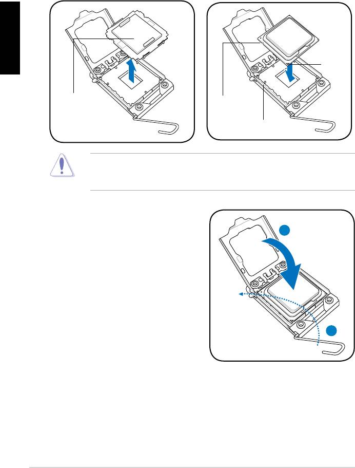
Türkçe
Altın
Üçgen
işareti
PnP kapağı
CPU çentiği
Hizalama anahtarı
A
oturana kadar ittirin.
B
46
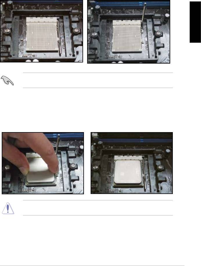
1.1.3 AMD AM2 Yuvası
Türkçe
oturur.
47
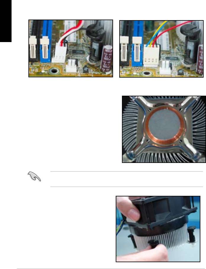
1.2 Isı emici ve fan montajı
Türkçe
Intel sertikalı ısı emici için:
macunla birlikte gelir. Bu durumda
48
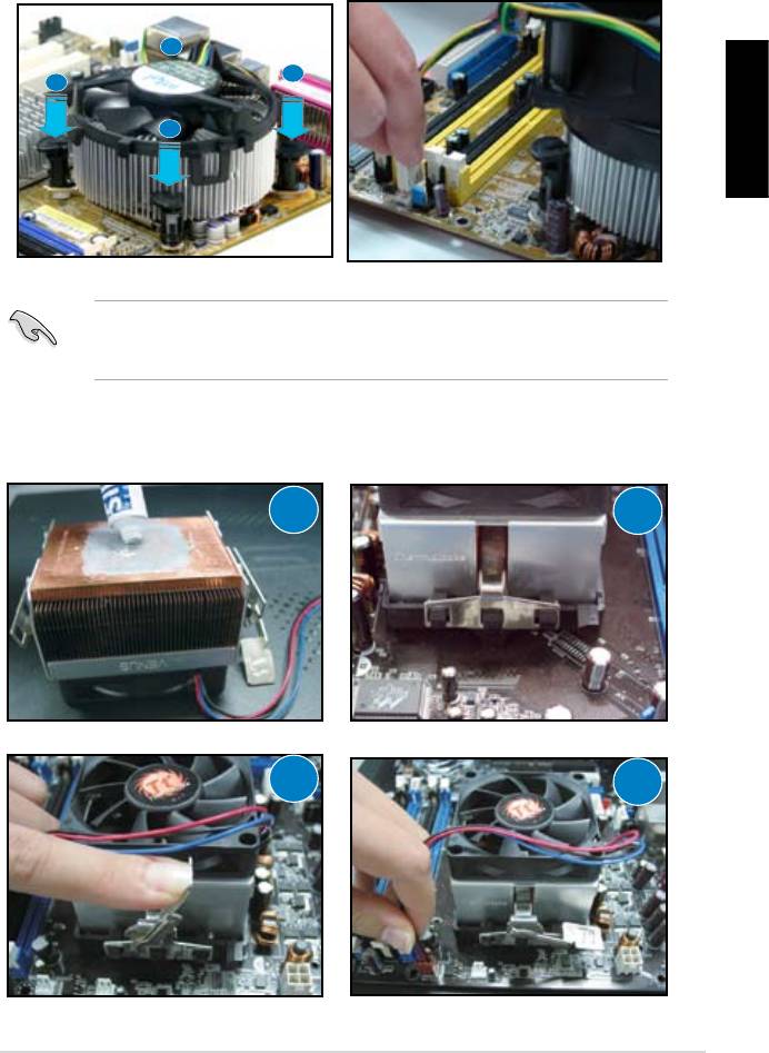
B
A
A
B
Türkçe
AMD sertikalı ısı emici için:
1
2
3
4
49
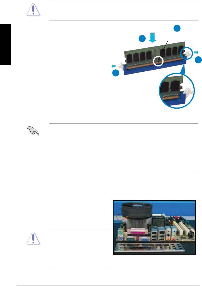
1.3 DIMM Montajı
2
Türkçe
DDR2 DIMM çentiği
3
1
1
Kilidi açık tutturucu klipsi
müracaat edin.
1.4 Anakart montajı
paketi ile birlikte gelen arka I/O
50
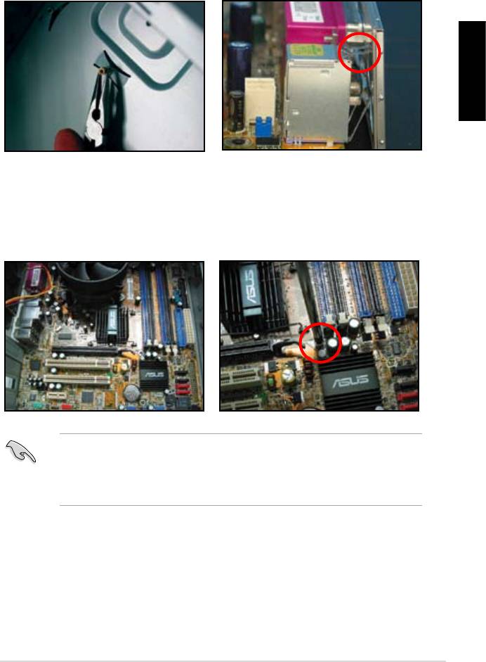
edin.
dikkatli olun.
Türkçe
51
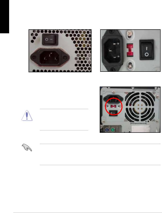
1.5 Güç kaynağı ünitesi montajı
Aktif PFC’li güç kaynağı:
Pasif PFC’li güç kaynağı:
Türkçe
verir.
müracaat edin.
52
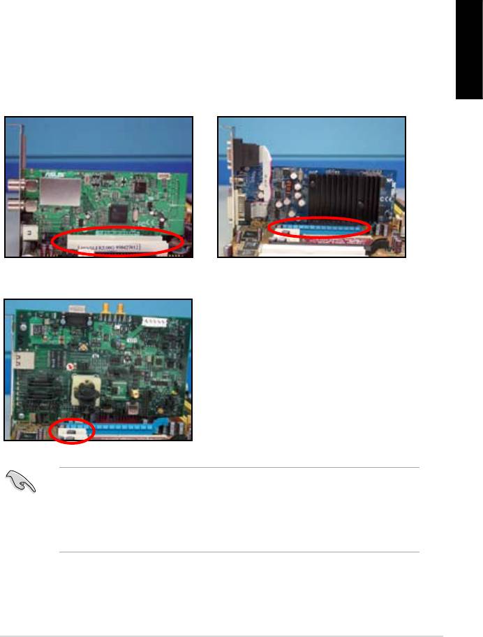
1.6 Genişletme kartı montajı
Türkçe
PCI kartı PCIE x16 kartı
PCIE x1 kartı
53
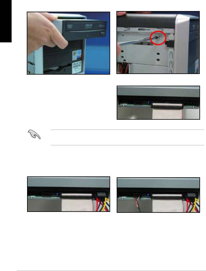
1.7 Disk sürücülerinin montajı
1.7.1 PATA optik disk sürücüsü
disk sürücüsünü vidalarla
Türkçe
pin1 ucudur ve optik sürücüdeki
gelmelidir.
4. 4 pinli güç kablosunu optik
5. Ses kablosunu optik sürücüdeki
54
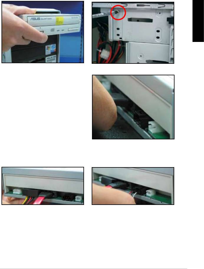
1.7.2 SATA optik disk sürücüsü
disk sürücüsünü vidalarla
Türkçe
5. Ses kablosunu optik sürücüdeki
55
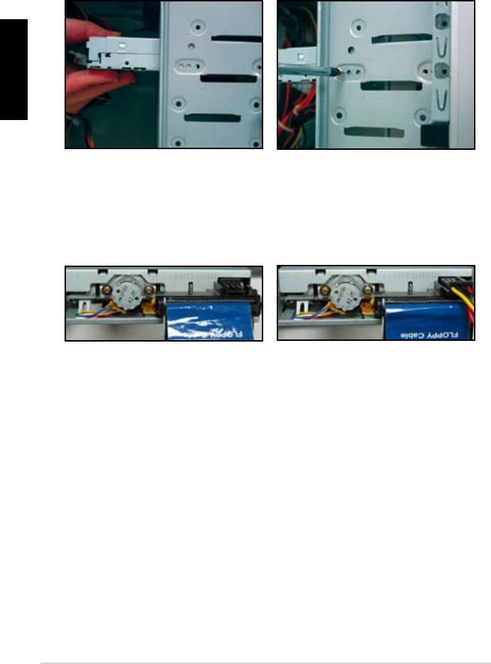
1.7.3 Disket sürücü
Türkçe
56
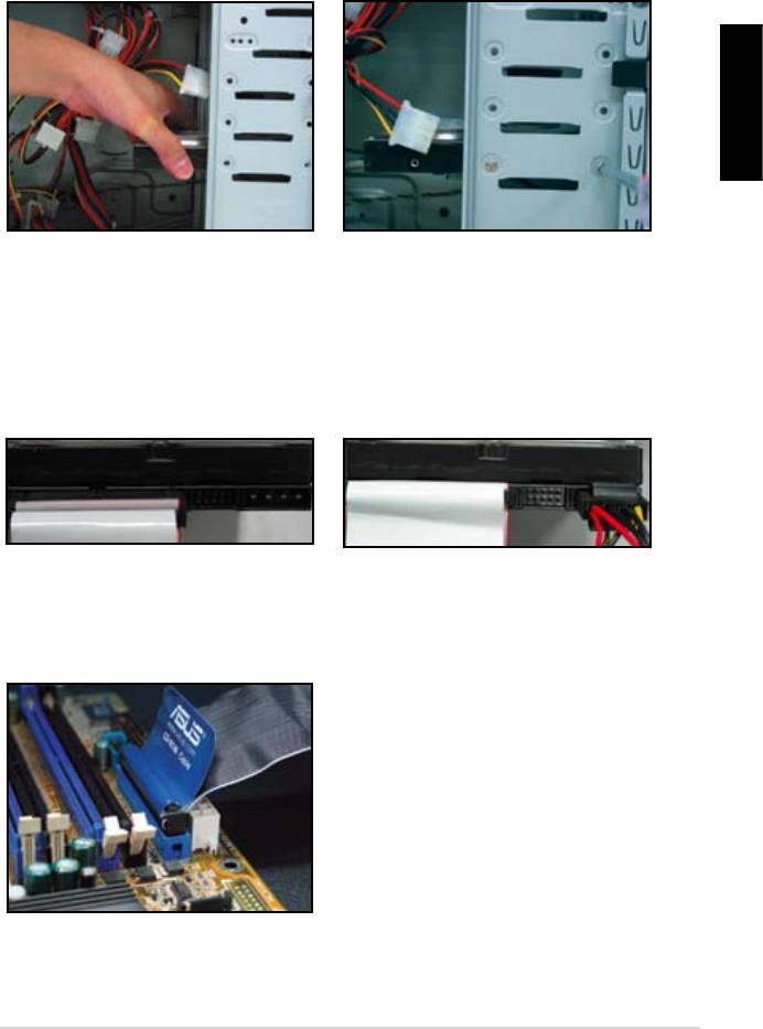
1.7.4 PATA sabit disk sürücü
Türkçe
4. 4 pinli güç kablosunu sabit disk
57
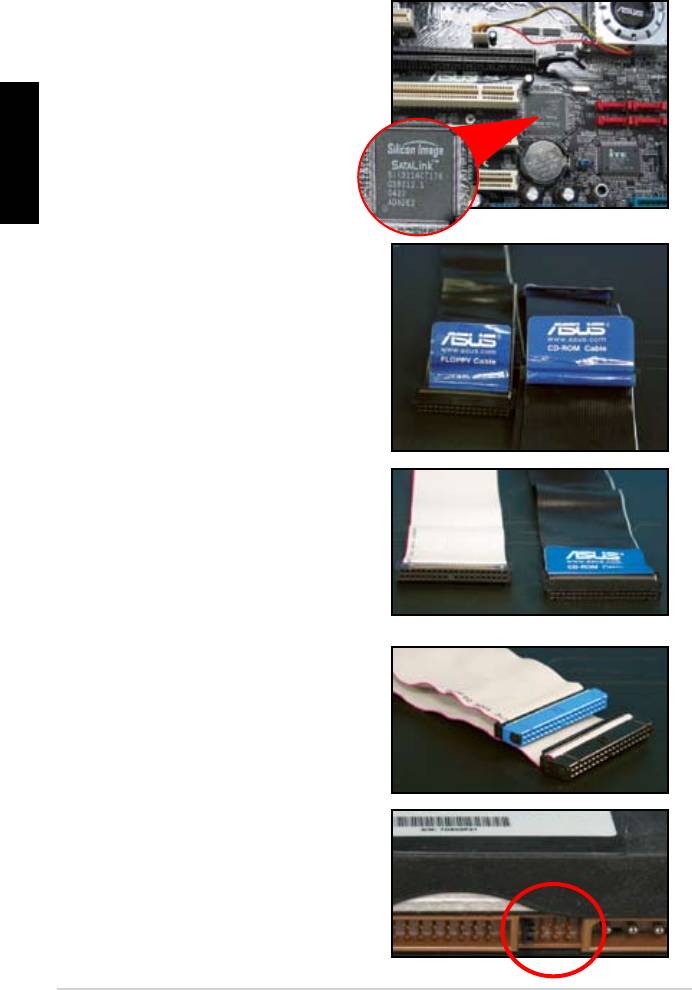
PATA sabit disk sürücü montajı ile ilgili notlar
Türkçe
• Kablolar çekme uçlu olarak
sadece kablo etiketlerine göre
Pinlere hasar gelmesini önlemek
çekerek kesin.
ATA66/100/133 disk sürücüler
için sadece 80‑telli kablo daha
kablolar genellikle optik sürücüler
içindir.
• Kablo konnektörü renk kodludur.
Mavi olan ana konnektördür,
sürücü içindir.
58
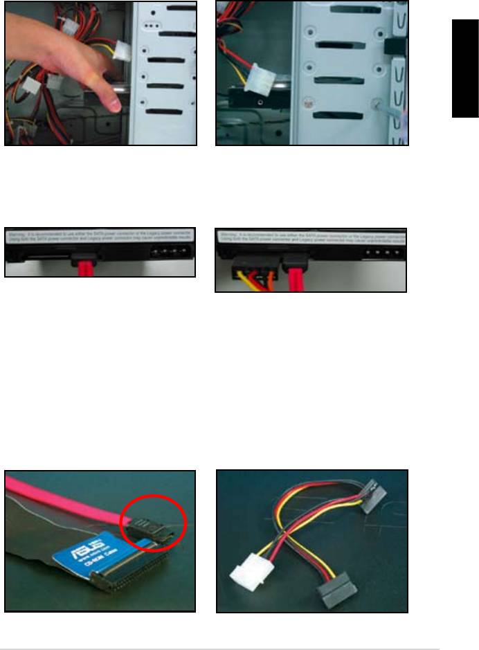
1.7.5 SATA sabit disk sürücü
Türkçe
4. SATA güç kablosunu sabit disk
oturabilir.
SATA sabit disk sürücü montajı ile ilgili notlar
• SATA güç kablosu konnektörü
geleneksel 4 pinli güç
kablolama ile ilgili meselelere
konnektörü içermemesi durumunda
59
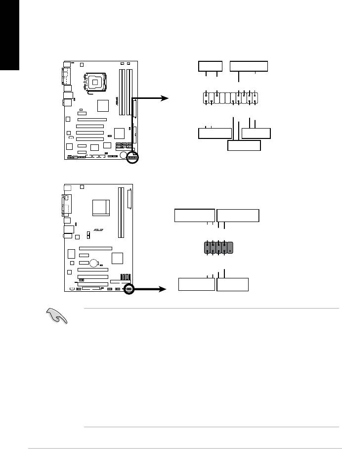
1.8 Ön panel kabloları
Türkçe
60
M2N-X
Reset
ANE
RESET
PLED SPEAKER
P5B-E
PLED+
PLED-
+5V
Ground
Ground
Speaker
®
PANEL
PWR
Reset
Ground
Ground
IDE_LED+
IDE_LED-
IDE_LED
RESET
PWRSW
*
Requires an ATX power supply.
20-8 pinli ön panel konnektörü
PIN1
PIN1
10-1 pinli ön panel konnektörü
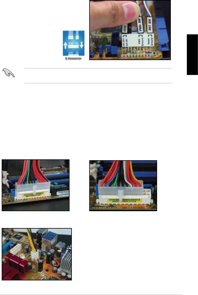
ASUS Q-Konnektör
müracaat edin.
Türkçe
1.9 ATX gücünün bağlanması
20 pinli güç konnektörü
24 pinli güç konnektörü
(24 pinli dişi karşılığında)
4 pinli güç konnektörü
61
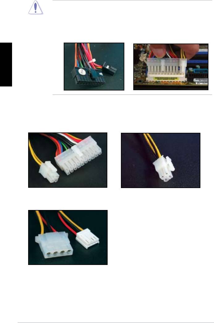
Türkçe
Güç konnektörleri
20+4 (24) pin ATX konnektör
4 pinli ATX konnektör
çevre birim güç konnektörü (sol)
disket güç konektörü (sağ)
62
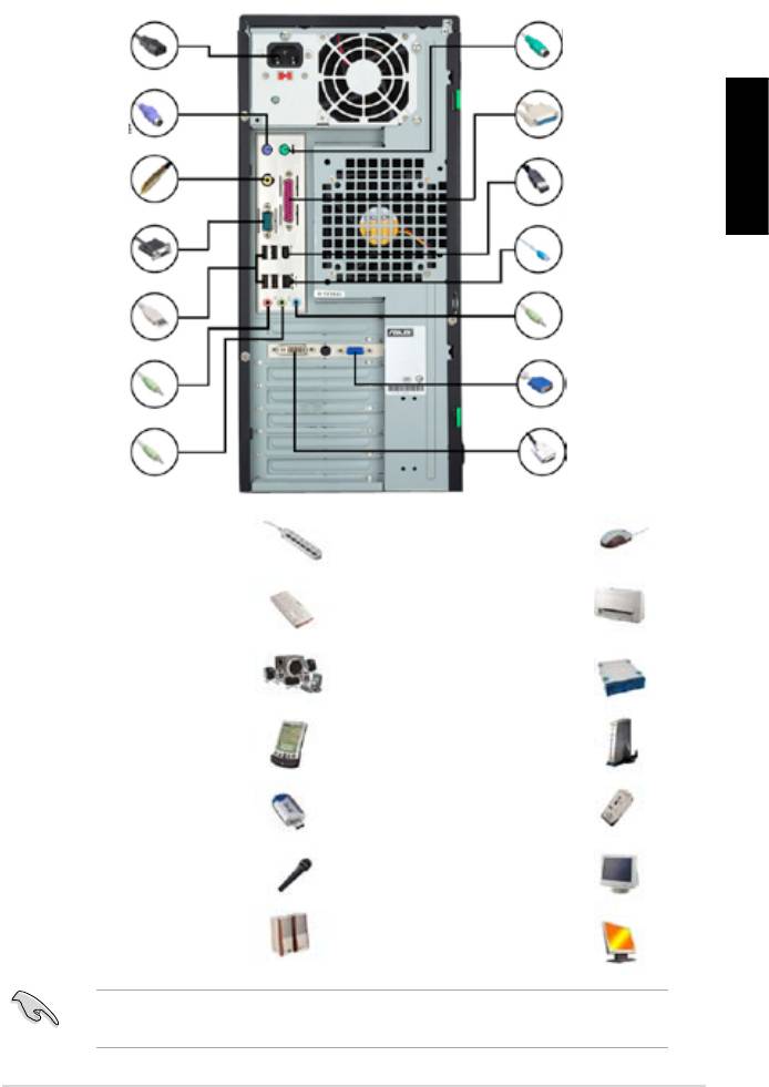
1.10 Çevre birimleri ve aksesuarlar
1. AC güç şi
8. PS/2 fare
portu
2. PS/2 klavye
9. Paralel port
portu
3. S/PDIF çıkış
10. IEEE1394 portu
Türkçe
portu
4. Seri port
11. LAN (RJ45)
portu
5. USB portu
12. Hat giriş
portu
13. Video grak
6. Mikrofon portu
adaptör portu
7. Hat çıkış portu 14. DVI portu
kablosu
5.1 hoparlör sistemi
sabit disk sürücü
63
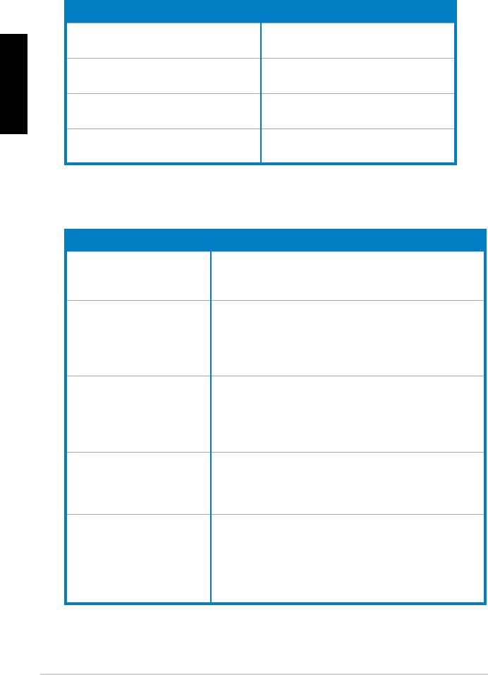
1.11 İlk kez çalıştırma
BIOS Bip Sesi Açıklama
sesi
Türkçe
bip sesi
(AMI BIOS)
Sorun Giderme
Sorun Eylem
emin olun.
Slave)
kontrol edin.
64

Bölüm 2: BIOS Yönetme/güncelleme
2.1 AFUDOSprogramı
Mevcut BIOS’un Kopyalanması
Türkçe
afudos /o[dosya adı]
A:\>afudos /oOLDBIOS1.rom
Ana dosya adı Uzatma adı
A:\>afudos /oOLDBIOS1.rom
AMI Firmware Update Utility — Version 1.19(ASUS V2.07(03.11.24BB))
Copyright (C) 2002 American Megatrends, Inc. All rights reserved.
Reading ash ….. done
Write to le…… ok
A:\>
BIOS dosyasının güncellenmesi
65
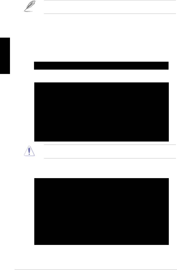
afudos /i[dosya adı]
Türkçe
A:\>afudos /iP5K3D.ROM
A:\>afudos /iP5K3D.ROM
AMI Firmware Update Utility — Version 1.19(ASUS V2.07(03.11.24BB))
Copyright (C) 2002 American Megatrends, Inc. All rights reserved.
WARNING!! Do not turn off power during ash BIOS
Reading le ……. done
Reading ash …… done
Advance Check ……
Erasing ash …… done
Writing ash …… 0x0008CC00 (9%)
A:\>afudos /iP5K3D.ROM
AMI Firmware Update Utility — Version 1.19(ASUS V2.07(03.11.24BB))
Copyright (C) 2002 American Megatrends, Inc. All rights reserved.
WARNING!! Do not turn off power during ash BIOS
Reading le ……. done
Reading ash …… done
Advance Check ……
Erasing ash …… done
Writing ash …… done
Verifying ash …. done
Please restart your computer
A:\>
66
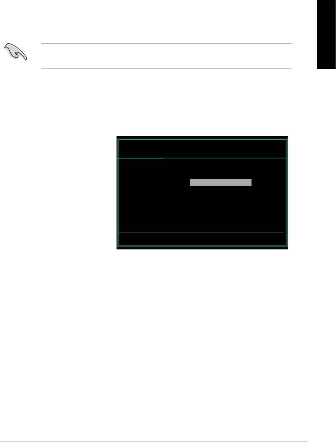
2.2 Award BIOS Flash Programı
BIOS güncelleme
FAT 16/12 biçimindeki
Türkçe
AwardBIOS Flash Utility for ASUS V1.14
(C) Phoenix Technologies Ltd. All Rights Reserved
gösterir) kullanarak
For NF590-SLI-M2N32-SLI-DELUXE DATE:03/30/2006
Flash Type — PMC Pm49FL004T LPC/FWH
File Name to Program:
diskinin ve Award BIOS
klasörüne geçin.
Message: Please input File Name!
67
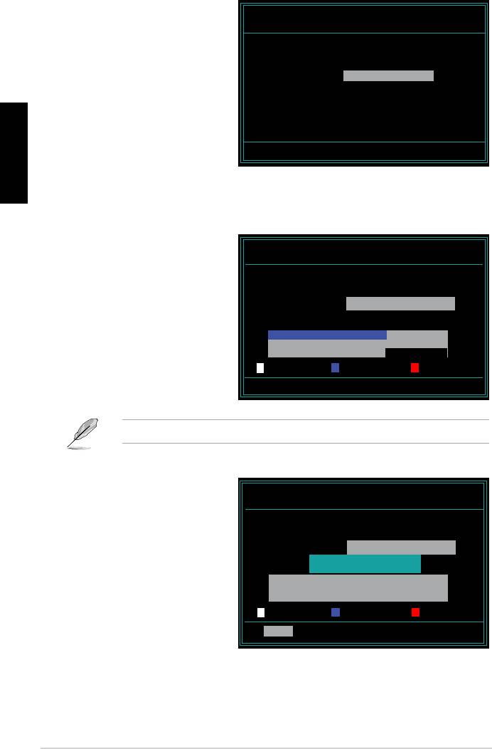
AwardBIOS Flash Utility for ASUS V1.14
(C) Phoenix Technologies Ltd. All Rights Reserved
For NF590-SLI-M2N32-SLI-DELUXE DATE:03/30/2006
Flash Type — PMC Pm49FL004T LPC/FWH
File Name to Program: M2N32SLI.bin
Türkçe
Message: Do You Want To Save Bios (Y/N)
AwardBIOS Flash Utility for ASUS V1.14
(C) Phoenix Technologies Ltd. All Rights Reserved
For NF590-SLI-M2N32-SLI-DELUXE DATE:03/30/2006
Flash Type — PMC Pm49FL004T LPC/FWH
File Name to Program: M2N32SLI.bin
Programming Flash Memory — OFE00 OK
Write OK No Update Write Fail
Warning: Don’t Turn Off Power Or Reset System!
AwardBIOS Flash Utility for ASUS V1.14
(C) Phoenix Technologies Ltd. All Rights Reserved
For NF590-SLI-M2N32-SLI-DELUXE DATE:03/30/2006
Flash Type — PMC Pm49FL004T LPC/FWH
File Name to Program: M2N32SLI.bin
Flashing Complete
Press <F1> to Continue
Write OK No Update Write Fail
F1
Reset
68
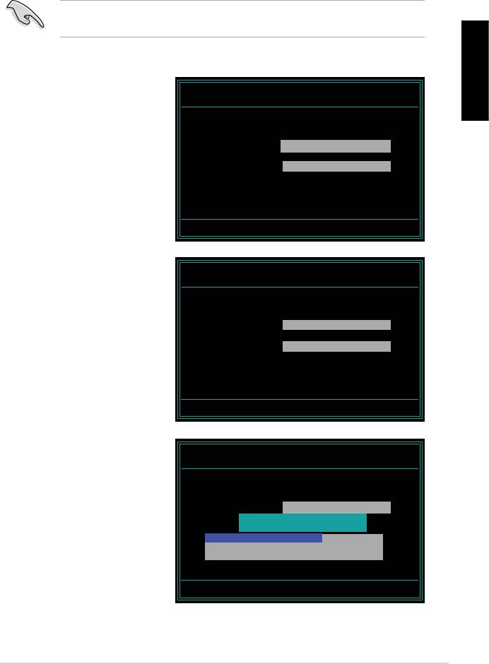
Mevcut BIOS dosyasının kaydedilmesi
1. Önceki ekrandaki 1.
AwardBIOS Flash Utility for ASUS V1.14
Türkçe
(C) Phoenix Technologies Ltd. All Rights Reserved
For NF590-SLI-M2N32-SLI-DELUXE DATE:03/30/2006
Flash Type — PMC Pm49FL004T LPC/FWH
2. Program mevcut BIOS
File Name to Program: 0112.bin
Save current BIOS as:
belirir.
Message:
AwardBIOS Flash Utility for ASUS V1.14
(C) Phoenix Technologies Ltd. All Rights Reserved
For NF590-SLI-M2N32-SLI-DELUXE DATE:03/30/2006
Flash Type — PMC Pm49FL004T LPC/FWH
File Name to Program: 0112.bin
Checksum: 810DH
Save current BIOS as: 0113.bin
Message: Please Wait!
4. Program mevcut BIOS
AwardBIOS Flash Utility for ASUS V1.14
(C) Phoenix Technologies Ltd. All Rights Reserved
For NF590-SLI-M2N32-SLI-DELUXE DATE:03/30/2006
Flash Type — PMC Pm49FL004T LPC/FWH
File Name to Program: 0113.bin
Now Backup System BIOS to
File!
Message: Please Wait!
69

2.3 ASUSGüncellemeprogramı
®
Türkçe
• BIOS sürüm bilgilerinin görüntülenmesi.
ASUS Güncellemesinin Kurulması
Sürücüler menüsü belirir.
2. ProgramlarASUS Güncellemesini Kur’a
70
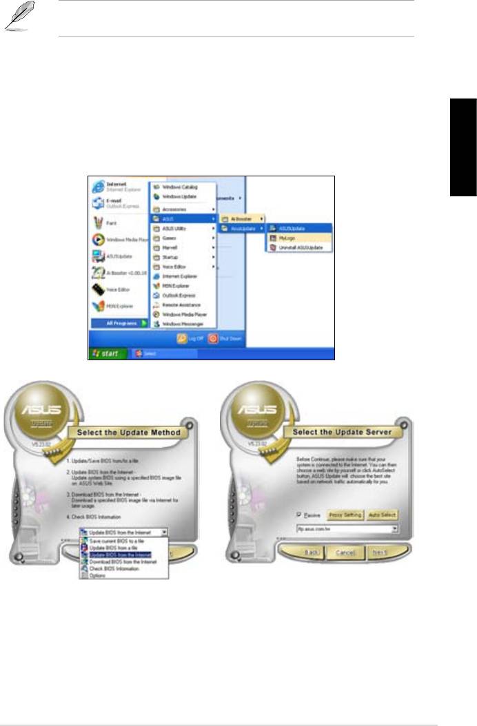
®
BIOS’un internetten güncellenmesi
1. Başlat > Programlar > ASUS > ASUSUpdate > ASUSUpdate
®
Türkçe
BIOS’u
İnternetten Güncelle
İleri
Oto Seçİleri
71
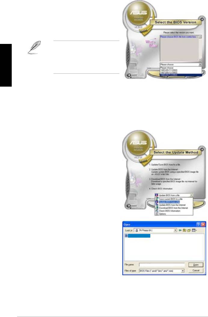
BIOS sürümünü seçin. İleri
Türkçe
BIOS’un BIOS dosyasından güncelleme
1. Başlat > Programlar > ASUS > ASUSUpdate > ASUSUpdate
®
BIOS’u
Dosyadan Güncelle
İleri
Açık pencereden
Aç
P5K3 Deluxe
getirin.
P5K3 Deluxe
72
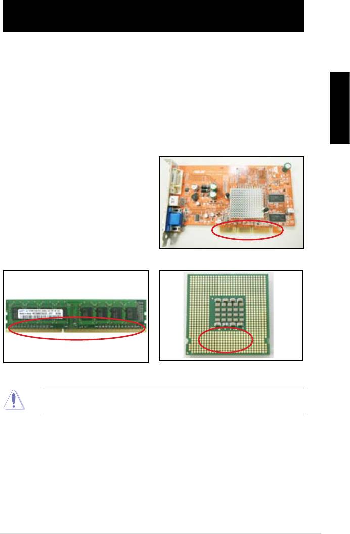
Bölüm 3: Sorun Giderme
3.1 Anakart DIY için Sorun Giderme
Türkçe
3.1.1 Temel sorun giderme
A. Kötü bağlantı
VGA kartı altın kontak
DIMM altın kontak
LGA775 işlemci altın kontak noktaları
73
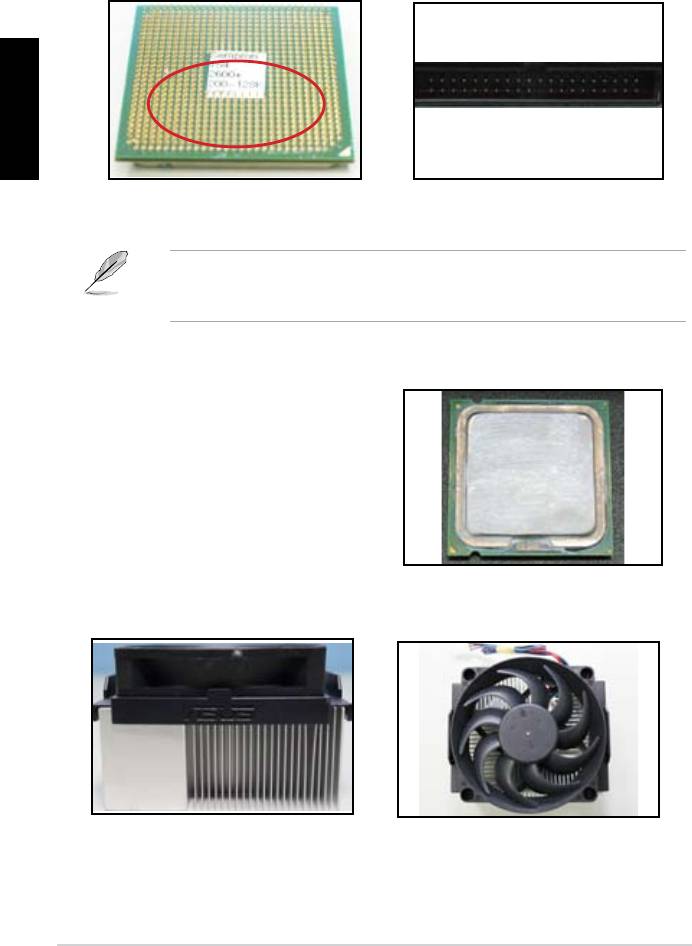
Türkçe
AMD CPU altın pinler
Konektör pinleri
B. CPU’nun aşırı ısınması
CPU yüzeyi
Isı emici ve fan yan görünümü
Isı emici ve fan üst görünümü
74
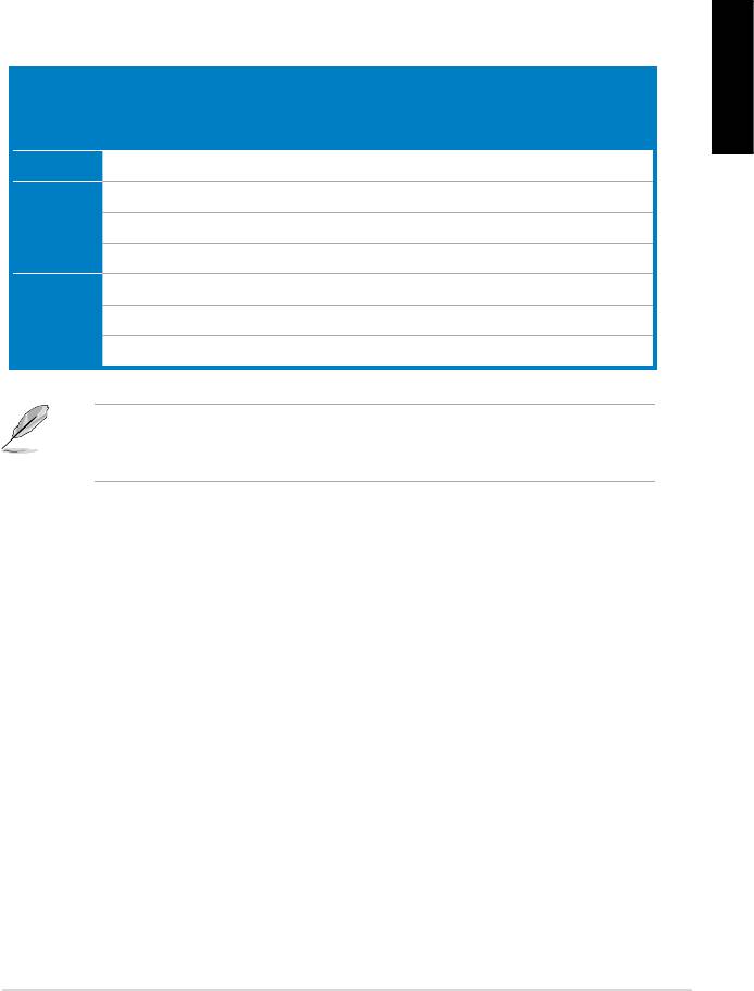
3.2 Diğer yaygın sorunlar
emin olun.
gösterilecektir.
Kontrol öğeleri
Türkçe
Güç LED’i Ekran
Isı emici
BIOS Bip
Hata
Referans
göstergesi
ve fan
Sesleri
mesajları
sayfa
Güç yok N/A 3‑4
Ekran
N/A 3‑5
göstergesi
N/A 3‑5
yok
Evet N//A 3‑5
İşletim
Evet Evet Evet 3‑5
Sistemine
Evet Evet 3‑5
Giriş
Başarısız
Evet 3‑5
destek ekibi ile temasa geçin.
75
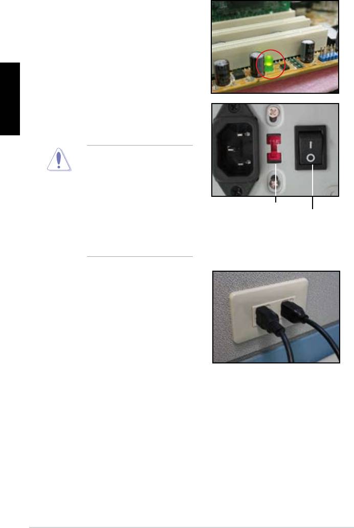
3.2.1 Güç yok
Türkçe
emin olun.
AC giriş voltaj düğmesi
Güç düğmesi
“—”: Açık;
“O”: Kapalı
• Sistem ve monitöre ait güç
76

3.2.2 Ön yükleme başarısız; Görüntü yok
olun.
Türkçe
olun.
3.2.3 İşletim sistemine giriş başarısız
ile temasa geçin.
gerekebilir.
77

Türkçe
gerekebilir.
3.2.4 Sıkça Sorulan Sorular
normaldir.
78

Bölüm 4: Bilgisayar bakımı ile ilgili ipuçları
4.1 Bilgisayarınızın uygun bakımı
4.2 Temel bilgiler
Türkçe
olur.
4.3 Kullanım bilgileri
4.4 İpuçları
79

Türkçe
80
Краткое содержание страницы № 1
P5KPL-AM SE
Motherboard
Краткое содержание страницы № 2
E4323 Second Edition V2 November 2008 Copyright © 2008 ASUSTeK Computer Inc. All Rights Reserved. No part of this manual, including the products and software described in it, may be reproduced, transmitted, transcribed, stored in a retrieval system, or translated into any language in any form or by any means, except documentation kept by the purchaser for backup purposes, without the express written permission of ASUSTeK Computer Inc. (“ASUS”). Product warranty or service will not be extende
Краткое содержание страницы № 3
Contents Notices ……………………………………………………………………………………………. v Safety information ………………………………………………………………………….. vi About this guide …………………………………………………………………………….. vi P5KPL-AM SE specifications summary ………………………………………….. viii Chapter 1: Product information 1.1 Before you proceed ……….
Краткое содержание страницы № 4
Contents 2.3.3 Primary IDE/SATA ………………………………………………….. 2-5 2.3.4 Storage Configuration …………………………………………….. 2-5 2.3.5 System Information ………………………………………………… 2-6 2.4 Advanced menu ………………………………………………………………… 2-6 2.4.1 JumperFree Configuration ………………………………………. 2-6 2.4.2 USB Configuration ………………………
Краткое содержание страницы № 5
Notices Federal Communications Commission Statement This device complies with Part 15 of the FCC Rules. Operation is subject to the following two conditions: • This device may not cause harmful interference, and • This device must accept any interference received including interference that may cause undesired operation. This equipment has been tested and found to comply with the limits for a Class B digital device, pursuant to Part 15 of the FCC Rules. These limits are designed to provide r
Краткое содержание страницы № 6
Safety information Electrical safety • To prevent electric shock hazard, disconnect the power cable from the electric outlet before relocating the system. • When adding or removing devices to or from the system, ensure that the power cables for the devices are unplugged before the signal cables are connected. If possible, disconnect all power cables from the existing system before you add a device. • Before connecting or removing signal cables from the motherboard, ensure that all power cabl
Краткое содержание страницы № 7
Conventions used in this guide To ensure that you perform certain tasks properly, take note of the following symbols used throughout this manual. DANGER/WARNING: Information to prevent injury to yourself when trying to complete a task. CAUTION: Information to prevent damage to the components when trying to complete a task. IMPORTANT: Instructions that you MUST follow to complete a task. NOTE: Tips and additional information to help you complete a task. Where to find more info
Краткое содержание страницы № 8
P5KPL-AM SE specifications summary ® CPU LGA775 socket for Intel Core™2 Quad/ Core™2 ® ® Extreme / Core™2 Duo / Pentium D / Pentium 4 / ® Celeron E1000 Series and Celeron 400 Series Processors ® Compatible with Intel 05B / 05A / 06 processors ® Intel Hyper-Threading Technology ready (Refer to www.asus.com for Intel CPU support list) ® Chipset Northbridge: Intel G31 ® Southbridge: Intel ICH7 Front Side Bus 1600(O.C.) / 1333 / 1066 / 800 / 533MHz Memory Dual channel memory architecture
Краткое содержание страницы № 9
P5KPL-AM SE specifications summary Internal connectors 2 x USB 2.0 connectors supports additional 4 USB ports 1 x internal speaker connector 2 x Serial ATA connectors 1 x CPU fan connector 1 x Chassis fan connector 1 x CD audio in connector 1 x 24-pin EATXPWR 12 V power connector 1 x 4-pin ATX 12 V power connector 1 x Front panel High Definition audio connector 1 x System Panel connector ASUS Exclusive SFS (Stepless Frequency Selection) Overclocking Features — FSB turning from 133MHz
Краткое содержание страницы № 10
Chapter 1 Product introduction ® Thank you for buying an ASUS P5KPL-AM SE motherboard! Before you start installing the motherboard, and hardware devices on it, check the items in your motherboard package. Refer to page ix for the list of accessories. If any of the items is damaged or missing, contact your retailer. 1.1 Before you proceed Take note of the following precautions before you install motherboard components or change any motherboard settings. • Unplug the power cord from the wall s
Краткое содержание страницы № 11
1.2 Motherboard overview 1.2.1 Motherboard layout Ensure that you install the motherboard into the chassis in the correct orientation. The edge with external ports goes to the rear part of the chassis. 18.3cm(7.2in) KBMS ATX12V CPU_FAN LGA775 USB34 Place this side towards LAN1_USB12 the rear of the chassis. ® Intel G31 CHA_FAN AUDIO RTL 8102FL PCIEX16 Lithium Cell CMOS Power ® Super Intel I/O ICH7 PCIEX1_1 P5KPL-AM SE SPEAKER PCI1 CLRTC ALC662 8Mb BIOS USBPW5-8 F_PANEL SB_PWR USB56 PRI_IDE US
Краткое содержание страницы № 12
1.3 Central Processing Unit (CPU) ® The motherboard comes with a surface mount LGA775 socket designed for the Intel Core ® ® ® ™2 Quad / Core™2 Extreme / Core™2 Duo / Pentium D / Pentium 4 and Celeron E1000 Series and Celeron 400 Series processors. • Ensure that all power cables are unplugged before installing the CPU. • Upon purchase of the motherboard, make sure that the PnP cap is on the socket and the socket contacts are not bent. Contact your retailer immediately if the PnP cap is miss
Краткое содержание страницы № 13
• You may install varying memory sizes in Channel A and Channel B. The system maps the total size of the lower-sized channel for the dual-channel configuration. Any excess memory from the higher-sized channel is then mapped for single-channel operation. • Always install DIMMs with the same CAS latency. For optimum compatibility, we recommend that you obtain memory modules from the same vendor. • Due to the memory address limitation on 32-bit Windows OS, when you install 4GB or more memory o
Краткое содержание страницы № 14
DIMM support S S / Size Vendor Model CL Brand Component DS A* B* 1G Apacer 78.01092.420 5 Elpida DS E5108AE-6E-E • • 1G Apacer AU01GE667C5KBGC 5 Apacer DS AM4B5708MIJS7E0627B • • 512MB ADATA M20EL5G3H3160B1C0Z N/A Elpida SS E5108AE-6E-E • • 512MB ADATA M20AD5G3H3166I1C52 N/A ADATA SS AD29608A8A-3EG20648 • • 512MB ADATA M20AD5G3H3166I1C52 N/A ADATA SS AD29608A8A-3EG20718 • • 1G ADATA M2OAD5G3I4176I1C52 N/A ADATA DS AD29608A8A-3EG20645 • • 512MB VDATA M2GVD5G3H31A4I1C52 N/A VDATA SS VD29608
Краткое содержание страницы № 15
DIMM support S S / Size Vendor Model CL Brand Component DS A* B* 1G Samsung KR M378T2953CZ3-CE7 N/A Samsung DS K4T51083QC-ZCE7 • • 256MB Qimonda HYS64T32001HU-2.5-A N/A Qimonda SS HYB18T256800AF25SSS49313 • • 512MB Qimonda HYS64T64020HU-2.5-A N/A Qimonda DS HYB18T256800AF25SSS25063 • • 1G Corsair CM2X1024-6400 5 Corsair DS Heat-Sink Package • • 1G Corsair XMS2-6400 4 Corsair DS Heat-Sink Package • • 1G Corsair XMS2-6400 5 Corsair DS Heat-Sink Package • • 512MB HY HYMP564U64AP8-S6 AA N/A H
Краткое содержание страницы № 16
1.5 Expansion slots In the future, you may need to install expansion cards. Refer to the technical documentation that come with your expansion card for installation details. Ensure to unplug the power cord before adding or removing expansion cards. Failure to do so may cause you physical injury and damage motherboard components. 1.5.1 PCI slot The PCI slot supports cards such as LAN cards, SCSI cards, USB cards, and other cards that comply with the PCI specifications. 1.5.2 PCI Express x1 slo
Краткое содержание страницы № 17
2. Clear RTC RAM (CLRTC) This jumper allows you to clear the Real Time Clock (RTC) RAM in CMOS. You can clear the CMOS memory of date, time, and system setup parameters by erasing the CMOS RTC RAM data. The onboard button cell battery powers the RAM data in CMOS, which include system setup information such as system •words. To erase the RTC RAM: 1. Turn OFF the computer and unplug the power cord. 2. Remove the onboard battery. 3. Move the jumper cap from pins 1-2 (default) to pins 2-3. Keep
Краткое содержание страницы № 18
3. Keyboard/mouse power (3-pin PS2_USBPW1-4) This jumper allows you to enable or disable the keyboard/mouse and USB port 5-6 wake-up feature. When you set this jumper to pins 2-3 (+5VSB), you can wake up the computer by pressing a key on the keyboard (the default is the Space Bar), clicking the mouse, or using a USB device. This feature requires an ATX power supply that can supply at least 1A on the +5VSB lead, and a corresponding setting in the BIOS. The USBPW56 jumper is for the rear USB
Краткое содержание страницы № 19
3. Line In port (light blue). This port connects to the tape, CD, DVD player, or other audio sources. 4. Line Out port (lime). This port connects to a headphone or a speaker. In 4-channel and 6-channel configuration, the function of this port becomes Front Speaker Out. 5. Microphone port (pink). This port connects to a microphone. Refer to the audio configuration table below for the function of the audio ports in 2, 4, or 6-channel configuration. Audio 2, 4, 6-channel configuration Port Head
Краткое содержание страницы № 20
2. IDE connector (40-1 pin PRI_IDE) The onboard IDE connector is for the Ultra DMA 100/66/33 signal cable. There are three connectors on each Ultra DMA 100/66/33 signal cable: blue, black, and gray. Connect the blue connector to the motherboard’s IDE connector, then select one of the following modes to configure your device. Driver Jumper setting Mode of device(s) Cable connector Single device Cable-Selected or Master — Black Two devices Cable-Select Master Black Slave Gray Master Master Blac