Руководства пользователя
Версия T4204
1.97 MB
Motherboard Installation Guide (Traditional Chinese)
Версия C4204
1.83 MB
Motherboard Installation Guide (Simplified Chinese)
Версия QJ4204
1.68 MB
Motherboard Installation Guide (Japanese)
Версия QG4204
1.6 MB
Motherboard Installation Guide (German)
Версия QF4204
1.59 MB
Motherboard Installation Guide (French)
Версия Q4204
43.39 MB
Motherboard Installation Guide (Multiple Languages)
Версия t4039
8.27 MB
P5K SE/EPU user’s manual (Traditional Chinese)
Версия f4039b
3.02 MB
P5K SE/EPU user’s manual (French)
Версия E4039
5.04 MB
P5K SE/EPU user’s manual(English)
Версия C3684
3.29 MB
P5K SE/EPU user’s manual(Simplified Chinese)
Версия T3684
3.37 MB
P5K SE/EPU user’s manual(Traditional Chinese)
Версия E3684
5.04 MB
P5K SE/EPU user’s manual(English)
Версия T2437
2.57 MB
Motherboard DIY Troubleshooting Guide (Traditional Chinese version)
- Manuals
- Brands
- Asus Manuals
- Motherboard
- P5K SE EPU
Manuals and User Guides for Asus P5K SE EPU. We have 5 Asus P5K SE EPU manuals available for free PDF download: Installation Manual, User Manual
Asus P5K SE EPU User Manual (134 pages)
User Manual
Brand: Asus
|
Category: Motherboard
|
Size: 5.48 MB
Table of Contents
-
Table of Contents
3
-
Contents
4
-
Canadian Department of Communications Statement
7
-
Federal Communications Commission Statement
7
-
-
Notices
7
-
Electrical Safety
8
-
Safety Information
8
-
About this Guide
9
-
Conventions Used in this Guide
10
-
P5K SE/EPU Specifications Summary
11
-
Chapter 1: Product Introduction
13
-
Welcome
15
-
Package Contents
15
-
Special Features
16
-
Product Highlights
16
-
High Definition Audio
17
-
ASUS AI Lifestyle Features
18
-
ASUS Stylish Features
19
-
ASUS Intelligent Overclocking Features
20
-
-
-
Chapter 2: Hardware Information
21
-
Before You Proceed
23
-
Motherboard Overview
24
-
Placement Direction
24
-
Screw Holes
24
-
Motherboard Layout
25
-
Internal Connectors
25
-
Layout Contents
26
-
-
Central Processing Unit (CPU)
28
-
Installing the CPU
29
-
Installing the CPU Heatsink and Fan
31
-
-
System Memory
35
-
Overview
35
-
Memory Configurations
36
-
Asus P5K Se/Epu
39
-
Installing a DIMM
40
-
Removing a DIMM
40
-
-
Expansion Slots
41
-
Installing an Expansion Card
41
-
Configuring an Expansion Card
41
-
Interrupt Assignments
42
-
Irq Assignments for this Motherboard
42
-
PCI Slots
43
-
PCI Express X1 Slots
43
-
PCI Express X16 Slot
43
-
Clear Rtc Ram
44
-
-
Jumpers
44
-
Connectors
46
-
Rear Panel Connectors
46
-
Internal Connectors
48
-
Usb Connectors
52
-
Optical Drive Audio Connector
52
-
Chassis Intrusion Connector
54
-
Front Panel Audio Connector
54
-
System Panel Connector
56
-
-
-
-
Chapter 3: Powering up
59
-
Starting up for the First Time
61
-
Turning off the Computer
62
-
Using the os Shut down Function
62
-
Using the Dual Function Power Switch
62
-
-
-
Chapter 4: BIOS Setup
63
-
Managing and Updating Your BIOS
65
-
ASUS Update Utility
65
-
Creating a Bootable Floppy Disk
68
-
ASUS EZ Flash 2 Utility
69
-
AFUDOS Utility
70
-
ASUS Crashfree BIOS 3 Utility
72
-
-
BIOS Setup Program
73
-
BIOS Menu Screen
74
-
Menu Bar
74
-
Navigation Keys
74
-
Menu Items
75
-
Sub-Menu Items
75
-
Configuration Fields
75
-
Pop-Up Window
75
-
Scroll Bar
75
-
General Help
75
-
-
Main Menu
76
-
System Time
76
-
System Date
76
-
Legacy Diskette a
76
-
Sata 1-4
77
-
SATA Configuration
78
-
System Information
79
-
-
Advanced Menu
80
-
Jumperfree Configuration
80
-
Ai Net 2
83
-
USB Configuration
84
-
CPU Configuration
85
-
Chipset
86
-
Onboard Devices Configuration
87
-
PCI Pnp
88
-
-
Power Menu
89
-
Suspend Mode
89
-
Repost Video on S3 Resume
89
-
ACPI Version
89
-
ACPI APIC Support
89
-
APM Configuration
90
-
Hardware Monitor
91
-
-
Boot Menu
93
-
Boot Device Priority
93
-
Boot Settings Configuration
94
-
Security
95
-
Change User Password
96
-
Clear User Password
96
-
-
-
Tools Menu
97
-
ASUS EZ Flash 2
97
-
ASUS O.C. Profile
98
-
-
Exit Menu
99
-
-
Chapter 5: Software Support
101
-
Installing an Operating System
103
-
Support CD Information
103
-
Running the Support CD
103
-
Drivers Menu
104
-
Utilities Menu
105
-
Manual Menu
107
-
ASUS Contact Information
107
-
Other Information
108
-
Technical Support Form
109
-
-
Software Information
110
-
ASUS Mylogo2
110
-
Audio Configurations
112
-
Configuration Options
113
-
ASUS PC Probe II
116
-
ASUS AI Suite
122
-
ASUS EPU Utility — AI Gear 3
124
-
ASUS AI Nap
126
-
ASUS Q-Fan 2
127
-
ASUS AI Booster
128
-
-
-
Appendix: CPU Features
129
-
A.1 Intel ® EM64T
130
-
Intel ® EM64T
131
-
Enhanced Intel Speedstep Technology (EIST)
131
-
System Requirements
131
-
A.2.1 System Requirements
131
-
Using the EIST
132
-
-
Intel ® Hyper-Threading Technology
133
-
Using the Hyper-Threading Technology
133
-
Advertisement

Asus P5K SE EPU User Manual (136 pages)
P5K SE user’s manual
Brand: Asus
|
Category: Motherboard
|
Size: 3.53 MB
Table of Contents
-
Table of Contents
3
-
Canadian Department of Communications Statement
7
-
Federal Communications Commission Statement
7
-
Notices
7
-
Electrical Safety
8
-
Safety Information
8
-
About this Guide
9
-
Conventions Used in this Guide
10
-
P5K SE Specifications Summary
11
-
Chapter1: Product Introduction
15
-
Welcome
17
-
Package Contents
17
-
Special Features
18
-
Product Highlights
18
-
High Definition Audio
19
-
ASUS AI Lifestyle Features
20
-
ASUS Stylish Features
21
-
ASUS Intelligent Overclocking Features
22
-
-
-
Chapter2: Hardware Information
23
-
Before You Proceed
25
-
Motherboard Overview
26
-
Placement Direction
26
-
Screw Holes
26
-
Motherboard Layout
27
-
Layout Contents
28
-
-
Central Processing Unit (CPU)
30
-
Installing the CPU
31
-
Installing the CPU Heatsink and Fan
33
-
-
System Memory
37
-
Overview
37
-
Memory Configurations
38
-
Installing a DIMM
42
-
Removing a DIMM
42
-
-
Expansion Slots
43
-
Installing an Expansion Card
43
-
Configuring an Expansion Card
43
-
Interrupt Assignments
44
-
PCI Slots
45
-
PCI Express X1 Slots
45
-
PCI Express X16 Slots
45
-
-
Jumper
46
-
Jumpers
46
-
Clear RTC RAM (CLRTC)
46
-
To Erase RTC RAM
46
-
-
Connectors
48
-
Rear Panel Connectors
48
-
Internal Connectors
50
-
System Panel Connector
58
-
Q-Connector
59
-
-
-
-
Chapter3: Powering Up
61
-
Starting up for the First Time
63
-
Turning off the Computer
64
-
Using the os Shut down Function
64
-
Using the Dual Function Power Switch
64
-
-
-
Chapter4: BIOS Setup
65
-
Managing and Updating Your BIOS
67
-
ASUS Update Utility
67
-
Creating a Bootable Floppy Disk
70
-
ASUS EZ Flash 2 Utility
71
-
AFUDOS Utility
72
-
ASUS Crashfree BIOS 3 Utility
74
-
-
BIOS Setup Program
75
-
BIOS Menu Screen
76
-
Menu Bar
76
-
Navigation Keys
76
-
Menu Items
77
-
Sub-Menu Items
77
-
Configuration Fields
77
-
Pop-Up Window
77
-
Scroll Bar
77
-
General Help
77
-
-
Main Menu
78
-
System Time
78
-
System Date
78
-
Legacy Diskette a
78
-
Sata 1~4
79
-
SATA Configuration
80
-
System Information
81
-
-
Advanced Menu
82
-
Jumperfree Configuration
82
-
USB Configuration
86
-
CPU Configuration
87
-
Chipset
88
-
Onboard Devices Configuration
89
-
PCI Pnp
90
-
-
Power Menu
91
-
Suspend Mode [Auto]
91
-
Repost Video on S3 Resume [Disabled]
91
-
ACPI Version [Disabled]
91
-
ACPI APIC Support [Enabled]
91
-
APM Configuration
92
-
Hardware Monitor
93
-
-
Boot Menu
95
-
Boot Device Priority
95
-
Boot Settings Configuration
96
-
Security
97
-
Change User Password
98
-
Clear User Password
98
-
-
-
Tools Menu
99
-
ASUS EZ Flash 2
99
-
ASUS O.C. Profile
100
-
-
Exit Menu
101
-
-
Chapter5: Software Support
103
-
Installing an Operating System
105
-
Running the Support CD
105
-
Support CD Information
105
-
Drivers Menu
106
-
Utilities Menu
107
-
Manual Menu
109
-
ASUS Contact Information
109
-
Other Information
110
-
Technical Support Form
111
-
-
Software Information
112
-
ASUS Mylogo2
112
-
Audio Configurations
114
-
Configuration Options
115
-
ASUS PC Probe II
118
-
ASUS AI Suite
124
-
ASUS AI Gear2
126
-
ASUS AI Nap
127
-
ASUS Q-Fan 2
128
-
ASUS AI Booster
129
-
-
-
Appendix: CPU Features
131
-
A.1 Intel ® EM64T
132
-
Intel ® EM64T
133
-
Enhanced Intel Speedstep Technology (EIST)
133
-
System Requirements
133
-
A.2.1 System Requirements
133
-
Using the EIST
134
-
-
Intel ® Hyper-Threading Technology
135
-
Using the Hyper-Threading Technology
135
-
() Asus P5K SE EPU Installation Manual (136 pages)
Motherboard Installation Guide
Brand: Asus
|
Category: Motherboard
|
Size: 2.91 MB
Table of Contents
-
Table of Contents
3
-
安全性須知
7
-
電氣方面的安全性
7
-
操作方面的安全性
7
-
-
關於這本使用手冊
8
-
使用手冊的編排方式
8
-
提示符號
9
-
跳線帽及圖示說明
9
-
哪裡可以找到更多的產品資訊
9
-
代理商查詢
10
-
-
P5K Se 規格列表
11
-
歡迎加入華碩愛好者的行列
17
-
產品包裝
17
-
特殊功能
18
-
產品特寫
18
-
華碩 AI Lifestyle 功能
20
-
華碩系統診斷家 II
21
-
華碩特殊功能
22
-
華碩智慧型超頻功能
22
-
華碩 Mylogo2™
22
-
-
主機板安裝前
25
-
主機板概觀
26
-
主機板的擺放方向
26
-
螺絲孔位
26
-
主機板構造圖
27
-
主機板元件說明
28
-
-
中央處理器(Cpu
30
-
安裝中央處理器
31
-
安裝散熱片和風扇
33
-
卸除散熱器與風扇
35
-
-
系統記憶體
37
-
概觀
37
-
記憶體設定
38
-
安裝記憶體模組
42
-
取出記憶體模組
42
-
-
擴充插槽
43
-
安裝擴充卡
43
-
設定擴充卡
43
-
指定中斷要求
44
-
Pci 介面卡擴充插槽
45
-
PCI Express X1 介面卡插槽
45
-
PCI Express X16 介面卡插槽
45
-
-
跳線選擇區
46
-
Ami Bios
61
-
管理、更新您的 Bios 程式
65
-
華碩線上更新
65
-
製作一張開機片
68
-
使用華碩 EZ Flash 2 更新 BIOS 程式
69
-
使用 Afudos 程式更新 Bios
70
-
使用 Crashfree BIOS 3 程式回復 BIOS 程式
72
-
Bios 程式設定
73
-
Bios 程式選單介紹
74
-
操作功能鍵說明
74
-
程式功能表列說明
74
-
子選單
75
-
捲軸
75
-
線上操作說明
75
-
設定值
75
-
設定視窗
75
-
選單項目
75
-
Legacy Diskette a [1.44M, 3.5 In.]
76
-
System Date [Day XX/XX/XXXX]
76
-
System Time [XX:XX:XXXX]
76
-
主選單(Main Menu)
76
-
Sata 裝置 1-4(Sata 1-4)
77
-
系統資訊(System Information)
79
-
Jumperfree 設定(Jumperfree Configuration)
80
-
進階選單(Advanced Menu)
80
-
USB裝置設定(USB Configuration)
84
-
處理器設定(CPU Configuration)
85
-
晶片設定(Chipset)
86
-
PCI 隨插即用裝置(PCI Pnp)
88
-
ACPI APIC Support [Enabled]
89
-
ACPI Version [Disabled]
89
-
Repost Video on S3 Resume [Disabled]
89
-
Suspend Mode [Auto]
89
-
電源管理(Power Menu)
89
-
進階電源管理設定(APM Configuration)
90
-
系統監控功能(Hardware Monitor)
91
-
啟動裝置順序(Boot Device Priority)
93
-
啟動選單(Boot Menu)
93
-
啟動選項設定(Boot Settings Configuration)
94
-
安全性選單(Security)
95
-
Change User Password
96
-
Clear User Password
96
-
-
ASUS EZ Flash 2
97
-
工具選單(Tools Menu)
97
-
ASUS O.C. Profile
98
-
離開 BIOS 程式(Exit Menu)
99
-
驅動程式選單(Drivers Menu)
104
-
公用程式選單(Utilities Menu)
105
-
華碩 AI Suite 程式
105
-
華碩 AI Booster 程式
127
-
-
A.1 Intel EM64T 技術
131
-
A.2 增強型 Intel Speedstep 技術(EIST)
131
-
A.2.1 系統的必需條件
131
-
A.2.2 使用 Eist
132
-
-
A.3 Intel Hyper-Threading 技術
133
Advertisement
() Asus P5K SE EPU User Manual (44 pages)
User Manual
Brand: Asus
|
Category: Motherboard
|
Size: 2.12 MB
Table of Contents
-
Table of Contents
3
-
第一章 快速組裝步驟
5
-
安裝處理器
5
-
安裝 Intel LGA 775 處理器
5
-
安裝 Intel LGA1366 處理器
6
-
安裝 AMD Socket AM2 處理器
8
-
-
安裝 Cpu 散熱片與風扇
9
-
安裝記憶體
12
-
安裝主機板至機殼
13
-
安裝電源供應器
14
-
安裝各種介面卡
16
-
安裝儲存裝置
17
-
Pata CD-Rom(DVD-Rom)的安裝
17
-
Sata CD-Rom(DVD-Rom)的安裝
18
-
軟碟機的安裝
19
-
Pata 硬碟機的安裝
20
-
Sata 硬碟機的安裝
22
-
-
機殼前方控制面板的連接線
25
-
連接電源線
26
-
連接週邊設備與配件
28
-
開機測試
29
-
-
第二章 管理、更新您的 Bios
31
-
使用 Afudos 程式更新 Bios
31
-
使用 Awardbios Flash 程式更新 BIOS
33
-
華碩線上更新
35
-
-
第三章 常見問題排除
37
-
主機板 Diy 問題解決指南
37
-
基本問題排除
37
-
-
問題與處理方法
39
-
注意事項
39
-
-
常見問題 Q&A
42
-
-
第四章 保養小祕方
43
-
電腦保養小常識
43
-
基本須知
43
-
使用須知
43
-
小秘方
44
-

() Asus P5K SE EPU User Manual (8 pages)
User Manual
Brand: Asus
|
Category: Motherboard
|
Size: 2.8 MB
Advertisement
Related Products
-
Asus P5K SE/EPU
-
Asus P5K-VM
-
Asus P5K PREMIUM/WIFI-AP — Pearl Special Edition Motherboard
-
Asus P5K Pro
-
Asus P5KEPU — Motherboard — ATX
-
Asus P5KPL IPC/SI
-
Asus P5KC
-
Asus P5KPL-CM 1600
-
Asus P5KPL IN SI
-
Asus P5K DELUXE
Asus Categories
Motherboard
![]()
Laptop
![]()
Desktop
![]()
Monitor
![]()
Network Router
More Asus Manuals
-
Contents
-
Table of Contents
-
Bookmarks
Quick Links
Related Manuals for Asus P5K SE EPU
Summary of Contents for Asus P5K SE EPU
-
Page 1
P5K SE/EPU… -
Page 2
Product warranty or service will not be extended if: (1) the product is repaired, modified or altered, unless such repair, modification of alteration is authorized in writing by ASUS; or (2) the serial number of the product is defaced or missing. -
Page 3: Table Of Contents
Welcome! ………………1-1 Package contents …………….. 1-1 Special features …………….1-2 1.3.1 Product highlights …………1-2 1.3.2 ASUS AI Lifestyle features ……….1-4 1.3.3 ASUS Stylish features …………. 1-5 1.3.4 ASUS Intelligent Overclocking features ……1-6 Chapter 2: Hardware information Before you proceed …………..
-
Page 4: Contents
4.1.1 ASUS Update utility …………4-1 4.1.2 Creating a bootable floppy disk ……..4-4 4.1.3 ASUS EZ Flash 2 utility ……….. 4-5 4.1.4 AFUDOS utility …………..4-6 4.1.5 ASUS CrashFree BIOS 3 utility ……..4-8 BIOS setup program …………..4-9 4.2.1…
-
Page 5
4.6.2 Boot Settings Configuration ………. 4-30 4.6.3 Security …………….. 4-31 Tools menu …………….. 4-33 4.7.1 ASUS EZ Flash 2 …………4-33 4.7.2 ASUS O.C. Profile …………4-34 Exit menu ………………4-35 Chapter 5: Software support Installing an operating system ……….. 5-1 Support CD information ………….. -
Page 6
Contents 5.3.3 ASUS PC Probe II …………5-14 5.3.4 ASUS AI Suite …………… 5-20 5.3.5 ASUS EPU Utility — AI Gear 3 ……..5-22 5.3.6 ASUS AI Nap …………..5-24 5.3.7 ASUS Q-Fan 2 ………….. 5-25 5.3.8 ASUS AI Booster …………5-26… -
Page 7: Notices
Notices Federal Communications Commission Statement This device complies with Part 15 of the FCC Rules. Operation is subject to the following two conditions: • This device may not cause harmful interference, and • This device must accept any interference received including interference that may cause undesired operation.
-
Page 8: Safety Information
Safety information Electrical safety • To prevent electrical shock hazard, disconnect the power cable from the electrical outlet before relocating the system. • When adding or removing devices to or from the system, ensure that the power cables for the devices are unplugged before the signal cables are connected. If possible, disconnect all power cables from the existing system before you add a device.
-
Page 9: About This Guide
Refer to the following sources for additional information and for product and software updates. ASUS websites The ASUS website provides updated information on ASUS hardware and software products. Refer to the ASUS contact information. Optional documentation Your product package may include optional documentation, such as warranty flyers, that may have been added by your dealer.
-
Page 10: Conventions Used In This Guide
Conventions used in this guide To make sure that you perform certain tasks properly, take note of the following symbols used throughout this manual. DANGER/WARNING: Information to prevent injury to yourself when trying to complete a task. CAUTION: Information to prevent damage to the components when trying to complete a task.
-
Page 11: P5K Se/Epu Specifications Summary
— 4 x 240-pin DIMM sockets support unbuffered non-ECC DDR2 1200/1066/800/667MHz memory modules — Supports up to 8 GB system memory * Refer to www.asus.com or this user manual for the Memory QVL (Qualified Vendors Lists). Expansion slots 1 x PCI Express™ x16 slot…
-
Page 12
System panel connector (Q-Connector) BIOS features 8 Mb Flash ROM, AMI BIOS, PnP, DMI 2.0, WfM 2.0, SM BIOS 2.3, ACPI 2.0a, ASUS EZ Flash 2, ASUS CrashFree BIOS 3 Manageability WfM 2.0, DMI 2.0, WOL by PME, WOR by PME, PXE… -
Page 13: Chapter 1: Product Introduction
This chapter describes the motherboard features and the new technologies it supports. Chapter 1: Product introduction…
-
Page 14
Chapter summary Welcome! ………………1-1 Package contents …………….. 1-1 Special features …………….1-2 ASUS P5K SE/EPU… -
Page 15: Welcome
® The motherboard delivers a host of new features and latest technologies, making it another standout in the long line of ASUS quality motherboards! Before you start installing the motherboard, and hardware devices on it, check the items in your package with the list below.
-
Page 16: Special Features
Green ASUS This motherboard and its packaging comply with the European Union’s Restriction on the use of Hazardous Substances (RoHS). This is in line with the ASUS vision of creating environment-friendly and recyclable products/packaging to safeguard consumers’ health while minimizing the impact on the environment.
-
Page 17: High Definition Audio
Audio CODEC enables high-quality 192KHz/24-bit audio output, jack-sensing feature, and multi-streaming technology that simultaneously sends different audio streams to different destinations. You can now talk to your partners on the headphone while playing multi-channel network games. See pages 2-24 and 2-25 for details. ASUS P5K SE/EPU…
-
Page 18: Asus Ai Lifestyle Features
1.3.2 ASUS AI Lifestyle features ASUS Power Saving Solution ASUS Power Saving solution makes system more stable and enhances the overclocking capability. ASUS EPU The ASUS EPU utilizes innovative technology to digitally monitor and tune the CPU power supply with improved VR responses in heavy or light loadings.
-
Page 19: Asus Stylish Features
Smart Support CD It provides a checklist to allow the user to see which drivers are already installed, as well as those that aren’t. When using ASUS PC Probe II, you can easily see the critical parts of the computer.
-
Page 20: Asus Intelligent Overclocking Features
1.3.4 ASUS Intelligent Overclocking features AI Booster The ASUS AI Booster allows you to overclock the CPU speed in Windows environment without the hassle of booting the BIOS. See page 5-26 for details. Precision Tweaker This feature allows you to fine tune the CPU/memory voltage and gradually increase the memory Front Side Bus (FSB) and PCI Express frequency at 1MHz increment to achieve maximum system performance.
-
Page 21: Chapter 2: Hardware Information
This chapter lists the hardware setup procedures that you have to perform when installing system components. It includes description of the jumpers and connectors on the motherboard. Chapter 2: Hardware information…
-
Page 22
Chapter summary Before you proceed …………..2-1 Motherboard overview …………..2-2 Central Processing Unit (CPU) ……….. 2-6 System memory …………….. 2-13 Expansion slots …………….2-19 Jumpers ………………2-22 Connectors …………….. 2-24 ASUS P5K SE/EPU… -
Page 23: Before You Proceed
The illustration below shows the location of the onboard LED. SB_PWR ® Standby Powered Power P5K SE/EPU Onboard LED ASUS P5K SE/EPU…
-
Page 24: Motherboard Overview
Motherboard overview Before you install the motherboard, study the configuration of your chassis to ensure that the motherboard fits into it. Make sure to unplug the power cord before installing or removing the motherboard. Failure to do so can cause you physical injury and damage motherboard components.
-
Page 25: Motherboard Layout
Lithium Cell PCIEX1_1 CMOS Power SATA2 SATA1 Super ALC883 SPDIF_OUT CLRTC PWR_FAN PCIEX1_2 USBPW9-12 CHA_FAN BIOS SB_PWR PRI_EIDE COM1 USB1112 USB910 AAFP PANEL Refer to 2.7 Connectors for more information about rear panel connectors and internal connectors. ASUS P5K SE/EPU…
-
Page 26: Layout Contents
2.2.4 Layout contents Slots Page DDR2 DIMM slots 2-13 PCI slots 2-21 PCI Express x1 slot 2-21 PCI Express x16 slots 2-21 Jumper Page Clear RTC RAM (3-pin CLRTC) 2-22 Keyboard power (3-pin PS2_USBPW) 2-23 USB device wake-up (3-pin USBPW1-4, USBPW5-8, USB9-12) 2-23 Rear panel connectors Page…
-
Page 27
• System power LED (2-pin PLED) • Hard disk drive activity LED (2-pin IDE_LED) • System warning speaker (4-pin SPEAKER) • ATX power button/soft-off button (2-pin PWRSW) • Reset button (2-pin RESET) ASUS Q-connector (system panel) 2-35 ASUS P5K SE/EPU… -
Page 28: Central Processing Unit (Cpu)
ASUS will shoulder the cost of repair only if the damage is shipment/transit-related. • Keep the cap after installing the motherboard. ASUS will process Return Merchandise Authorization (RMA) requests only if the motherboard comes with the cap on the LGA775 socket.
-
Page 29: Installing The Cpu
This side of the socket box should face you. To prevent damage to the socket pins, do not remove the PnP cap unless you are installing a CPU. Lift the load lever in the direction of the arrow to a 135º angle. ASUS P5K SE/EPU…
-
Page 30
Lift the load plate with your thumb and forefinger to a 100º angle (A), then push the PnP cap from the load plate window to remove (B). Load plate Alignment key Position the CPU over the socket, making sure that the gold triangle is on the bottom-left corner of the socket then fit the socket… -
Page 31: Installing The Cpu Heatsink And Fan
CPU fan connector. Motherboard hole Fastener Narrow end of the groove Make sure to orient each fastener with the narrow end of the groove pointing outward. (The photo shows the groove shaded for emphasis.) ASUS P5K SE/EPU…
-
Page 32
Push down two fasteners at a time in a diagonal sequence to secure the heatsink and fan assembly in place. Connect the CPU fan cable to the connector on the motherboard labeled CPU_FAN. CPU_FAN ® P5K SE/EPU CPU fan connector Do not forget to connect the CPU fan connector! Hardware monitoring errors can occur if you fail to plug this connector. -
Page 33
Rotate each fastener counterclockwise. Pull up two fasteners at a time in a diagonal sequence to disengage the heatsink and fan assembly from the motherboard. Carefully remove the heatsink and fan assembly from the motherboard. ASUS P5K SE/EPU 2-11… -
Page 34
Rotate each fastener clockwise to ensure correct orientation when reinstalling. Narrow end of the groove The narrow end of the groove should point outward after resetting. (The photo shows the groove shaded for emphasis.) Refer to the documentation in the boxed or stand-alone CPU fan package for detailed information on CPU fan installation. -
Page 35: System Memory
The motherboard comes with four Double Data Rate 2 (DDR2) Dual Inline Memory Modules (DIMM) sockets. The figure illustrates the location of the DDR2 DIMM sockets: ® P5K SE/EPU 240-pin DDR2 DIMM sockets Channel Sockets Channel A DIMM_A1 and DIMM_B1 Channel B DIMM_A2 and DIMM_B2 ASUS P5K SE/EPU 2-13…
-
Page 36: Memory Configurations
2.4.2 Memory configurations You may install 256 MB, 512 MB, 1 GB, and 2 GB unbuffered non-ECC DDR2 DIMMs into the DIMM sockets. Recommended Memory Configurations Sockets Mode DIMM_A1 DIMM_A2 DIMM_B1 DIMM_B2 Populated Single-Channel Populated Dual-channel (1) Populated Populated Dual-channel (2) Populated Populated Populated…
-
Page 37
CM2X1024 — 9136C5D / XMS9105V1.1 • If you install a DDR2-1066 memory module whose SPD is DDR2-800, make sure that you set the DRAM Frequency item in BIOS to [DDR2-1066MHz]. See section 4.4.1 Jumperfree Configuration for details. ASUS P5K SE/EPU 2-15… -
Page 38
P5K SE/EPU Motherboard Qualified Vendors Lists (QVL) DDR2-800 MHz capability DIMM support Chip Size Vendor Chip No. Part No. Brand 512MB KINGSTON K4T51083QC KVR800D2N5/512 • • • 1024MB KINGSTON Heat-Sink Package 4-4-4-12 KHX6400D2LL/1G • • 1024MB KINGSTON Heat-Sink Package 4-4-4-12 KHX6400D2LLK2/1GN •… -
Page 39: Asus P5K Se/Epu
Dual-channel memory configuration. • C*: Supports 4 modules inserted into both the yellow and black slots as two pairs of Dual-channel memory configuration. Visit the ASUS website for the latest DDR2-1066/800/667MHz QVL. ASUS P5K SE/EPU 2-17…
-
Page 40: Installing A Dimm
2.4.3 Installing a DIMM Unplug the power supply before adding or removing DIMMs or other system components. Failure to do so can cause severe damage to both the motherboard and the components. To install a DIMM: DDR2 DIMM notch Unlock a DIMM socket by pressing the retaining clips outward.
-
Page 41: Expansion Slots
IRQ” or that the cards do not need IRQ assignments. Otherwise, conflicts will arise between the two PCI groups, making the system unstable and the card inoperable. Refer to the table on the next page for details. ASUS P5K SE/EPU 2-19…
-
Page 42: Interrupt Assignments
2.5.3 Interrupt assignments Standard function System timer Keyboard controller Re-direct to IRQ#9 IRQ holder for PCI steering* Communications port (COM1)* IRQ holder for PCI steering* Floppy disk controller IRQ holder for PCI steering* System CMOS/Real Time Clock IRQ holder for PCI steering* IRQ holder for PCI steering* IRQ holder for PCI steering* IRQ holder for PCI steering*…
-
Page 43: Pci Slots
PCI Express x1 slot. 2.5.6 PCI Express x16 slot This motherboard supports one PCI Express x16 graphics card that complies with the PCI Express specifications. The figure shows a graphics card installed on the PCI Express x16 slot. ASUS P5K SE/EPU 2-21…
-
Page 44: Clear Rtc Ram
Jumpers Clear RTC RAM (3-pin CLRTC) This jumper allows you to clear the Real Time Clock (RTC) RAM in CMOS. You can clear the CMOS memory of date, time, and system setup parameters by erasing the CMOS RTC RAM data. The onboard button cell battery powers the RAM data in CMOS, which include system setup information such as system passwords.
-
Page 45
500mA on the +5VSB lead for each USB port; otherwise, the system would not power up. • The total current consumed must NOT exceed the power supply capability (+5VSB) whether under normal condition or in sleep mode. ASUS P5K SE/EPU 2-23… -
Page 46: Connectors
Connectors 2.7.1 Rear panel connectors PS/2 keyboard port (purple). This port is for a PS/2 keyboard. LAN (RJ-45) port. Supported by Gigabit LAN controller, this port allows Gigabit connection to a Local Area Network (LAN) through a network hub. Refer to the table below for the LAN port LED indications. Center/Subwoofer port (orange).
-
Page 47
12. Coaxial S/PDIF Out port. This port connects an external audio output device via a coaxial S/PDIF cable. 13. USB 2.0 ports 5 and 6. These two 4-pin Universal Serial Bus (USB) ports are available for connecting USB 2.0 devices. ASUS P5K SE/EPU 2-25… -
Page 48: Internal Connectors
2.7.2 Internal connectors Floppy disk drive connector (34-1 pin FLOPPY) This connector is for the provided floppy disk drive (FDD) signal cable. Insert one end of the cable to this connector, then connect the other end to the signal connector at the back of the floppy disk drive. Pin 5 on the connector is removed to prevent incorrect cable connection when using a FDD cable with a covered Pin 5.
-
Page 49
If any device jumper is set as “Cable-Select,” make sure all other device jumpers have the same setting. ® PRI_EIDE PIN 1 NOTE: Orient the red markings (usually zigzag) on the IDE ribbon cable to PIN 1. P5K SE/EPU IDE connector ASUS P5K SE/EPU 2-27… -
Page 50
ICH9 Serial ATA connectors (7-pin SATA1-4) These connectors are for the Serial ATA signal cables for Serial ATA hard disk drives. SATA3 SATA4 SATA1 SATA2 SATA3 SATA4 ® P5B SATA Connectors SATA2 SATA1 P5K SE/EPU SATA connectors When using the connectors in Standard IDE mode, connect the primary (boot) hard disk drive to the SATA1/2 connector. -
Page 51
Connect the S/PDIF Out module cable to this connector, then install the module to a slot opening at the back of the system chassis. ® SPDIF_OUT P5K SE/EPU Digital audio connector The S/PDIF module is purchased separately. ASUS P5K SE/EPU 2-29… -
Page 52: Usb Connectors
Never connect a 1394 cable to the USB connectors. Doing so will damage the motherboard! You can connect the front panel USB cable to the ASUS Q-Connector (USB, blue) first, and then install the Q-Connector (USB) to the USB connector onboard if your chassis supports front panel USB ports.
-
Page 53
® PWR_FAN CHA_FAN P5K SE/EPU Fan connectors Only the CPU_FAN and CHA_FAN connector support the ASUS Q-FAN 2 feature. Serial port connector (10-1 pin COM1) This connector is for a serial (COM) port. Connect the serial port module cable to this connector, then install the module to a slot opening at the back of the system chassis. -
Page 54: Chassis Intrusion Connector
Chassis intrusion connector (4-1 pin CHASSIS) This connector is for a chassis-mounted intrusion detection sensor or switch. Connect one end of the chassis intrusion sensor or switch cable to this connector. The chassis intrusion sensor or switch sends a high-level signal to this connector when a chassis component is removed or replaced.
-
Page 55
CPU: Intel Pentium Extreme 3.73GHz ® ® Memory: 512 MB DDR2 (x4) Graphics card: ASUS EAX1900XT Parallel ATA device: IDE hard disk drive Serial ATA device: SATA hard disk drive (x2) Optical drive: DVD-RW ASUS P5K SE/EPU 2-33… -
Page 56: System Panel Connector
12. System panel connector (20-8 pin PANEL) This connector supports several chassis-mounted functions. PLED SPEAKER PANEL ® RESET IDE_LED PWRSW Requires an ATX power supply. P5K SE/EPU System panel connector • System power LED (2-pin PLED) This 2-pin connector is for the system power LED. Connect the chassis power LED cable to this connector.
-
Page 57
Q-Connector (system panel) You can use ASUS Q-Connector to connect / disconnect chassis front panel cables by only a few steps. Directions below shows how to install ASUS Q-Connector. Step1. Connect correct front panel to ASUS Q-Connector first. You can refer to the marking on Q-Connector itself to know the detail pin definition. -
Page 58
2-36 Chapter 2: Hardware information… -
Page 59: Chapter 3: Powering Up
This chapter describes the power up sequence, the vocal POST messages, and ways of shutting down the system. Chapter 3: Powering up…
-
Page 60
Chapter summary Starting up for the first time …………3-1 Turning off the computer …………. 3-2 ASUS P5K SE/EPU… -
Page 61: Starting Up For The First Time
One continuous beep followed by three No VGA detected short beeps One continuous beep followed by four Hardware component failure short beeps At power on, hold down the <Delete> key to enter the BIOS Setup. Follow the instructions in Chapter 4. ASUS P5K SE/EPU…
-
Page 62: Turning Off The Computer
Turning off the computer 3.2.1 Using the OS shut down function If you are using Windows ® Click the Start button then select Turn Off Computer. Click the Turn Off button to shut down the computer. The power supply should turn off after Windows ®…
-
Page 63: Chapter 4: Bios Setup
This chapter tells how to change the system settings through the BIOS Setup menus. Detailed descriptions of the BIOS parameters are also provided. Chapter 4: BIOS setup…
-
Page 64
Chapter summary Managing and updating your BIOS ……….4-1 BIOS setup program …………..4-9 Main menu ……………… 4-12 Advanced menu …………….. 4-16 Power menu …………….4-25 Boot menu ……………… 4-29 Tools menu …………….. 4-33 Exit menu ………………4-35 ASUS P5K SE/EPU… -
Page 65: Managing And Updating Your Bios
ASUS Update (Updates the BIOS in Windows environment.) ® ASUS EZ Flash 2 (Updates the BIOS using a floppy disk or USB flash disk.) AFUDOS utility (Updates the BIOS using a bootable floppy disk.) ASUS CrashFree BIOS 3 (Updates the BIOS using a bootable floppy disk, USB flash disk or the motherboard support CD when the BIOS file fails or gets corrupted.)
-
Page 66
To update the BIOS through the Internet: desktop by clicking Start Launch the ASUS Update utility from the Windows ® > Programs > ASUS > ASUSUpdate > ASUSUpdate. The ASUS Update main window appears. Select Update BIOS from the Select the ASUS FTP site nearest… -
Page 67
To update the BIOS through a BIOS file: desktop by clicking Start Launch the ASUS Update utility from the Windows ® > Programs > ASUS > ASUSUpdate > ASUSUpdate. The ASUS Update main window appears. Select Update BIOS from a file option from the drop-down menu, then click Next. -
Page 68: Creating A Bootable Floppy Disk
4.1.2 Creating a bootable floppy disk Do either one of the following to create a bootable floppy disk. DOS environment a. Insert a 1.44MB floppy disk into the drive. b. At the DOS prompt, type format A:/S then press <Enter>. Windows XP environment ®…
-
Page 69: Asus Ez Flash 2 Utility
4.1.3 ASUS EZ Flash 2 utility The ASUS EZ Flash 2 feature allows you to update the BIOS without having to go through the long process of booting from a floppy disk and using a DOS-based utility. The EZ Flash 2 utility is built-in the BIOS chip so it is accessible by pressing <Alt>…
-
Page 70: Afudos Utility
Updating the BIOS file To update the BIOS file using the AFUDOS utility: Visit the ASUS website (www.asus.com) and download the latest BIOS file for the motherboard. Save the BIOS file to a bootable floppy disk. Chapter 4: BIOS setup…
-
Page 71
A:\>afudos /iP5KSE.ROM The utility verifies the file and starts updating the BIOS. A:\>afudos /iP5KSE.ROM AMI Firmware Update Utility — Version 1.19(ASUS V2.07(03.11.24BB)) Copyright (C) 2002 American Megatrends, Inc. All rights reserved. WARNING!! Do not turn off power during flash BIOS Reading file .. -
Page 72: Asus Crashfree Bios 3 Utility
4.1.5 ASUS CrashFree BIOS 3 utility The ASUS CrashFree BIOS 3 is an auto recovery tool that allows you to restore the BIOS file when it fails or gets corrupted during the updating process. You can update a corrupted BIOS file using the motherboard support CD or a USB flash disk that contains the updated BIOS file.
-
Page 73: Bios Setup Program
The BIOS setup screens shown in this section are for reference purposes only, and may not exactly match what you see on your screen. • Visit the ASUS website (www.asus.com) to download the latest BIOS file for this motherboard. ASUS P5K SE/EPU…
-
Page 74: Bios Menu Screen
4.2.1 BIOS menu screen Menu items Menu bar Configuration fields General help BIOS SETUP UTILITY Main Advanced Power Boot Tools Exit Use [ENTER], [TAB] or System Time [10:55:25] [SHIFT-TAB] to select System Date [Mon 01/28/2008] a field. Legacy Diskette A [1.44M, 3.5 in] Use [+] or [-] to configure system Time.
-
Page 75: Menu Items
Up/Down arrow keys or <Page Up> /<Page Down> keys to display the other items on the screen. 4.2.9 General help Pop-up window At the top right corner of the menu screen Scroll bar is a brief description of the selected item. ASUS P5K SE/EPU 4-11…
-
Page 76: Main Menu
Main menu When you enter the BIOS Setup program, the Main menu screen appears, giving you an overview of the basic system information. Refer to section 4.2.1 BIOS menu screen for information on the menu screen items and how to navigate through them. BIOS SETUP UTILITY Main Advanced…
-
Page 77: Sata 1-4
When set to [Disabled], the data transfer from and to the device occurs one sector at a time. Configuration options: [Disabled] [Auto] PIO Mode [Auto] Selects the PIO mode. Configuration options: [Auto] [0] [1] [2] [3] [4] ASUS P5K SE/EPU 4-13…
-
Page 78: Sata Configuration
DMA Mode [Auto] Selects the DMA mode. Configuration options: [Auto] [SWDMA0] [SWDMA1] [SWDMA2] [MWDMA0] [MWDMA1] [MWDMA2] [UDMA0] [UDMA1] [UDMA2] [UDMA3] [UDMA4] [UDMA5] SMART Monitoring [Auto] Sets the Smart Monitoring, Analysis, and Reporting Technology. Configuration options: [Auto] [Disabled] [Enabled] 32Bit Data Transfer [Enabled] Enables or disables 32-bit data transfer.
-
Page 79: System Information
Available : 1024 MB General Help Save and Exit Exit v02.58 (C)Copyright 1985-2007, American Megatrends, Inc. AMI BIOS Displays the auto-detected BIOS information. Processor Displays the auto-detected CPU specification. System Memory Displays the auto-detected system memory. ASUS P5K SE/EPU 4-15…
-
Page 80: Advanced Menu
Advanced menu The Advanced menu items allow you to change the settings for the CPU and other system devices. Take caution when changing the settings of the Advanced menu items. Incorrect field values can cause the system to malfunction. BIOS SETUP UTILITY Main Advanced Power…
-
Page 81
Allows you to set the DDR2 operating frequency. Configuration options: [Auto] [DDR2-667MHz] [DDR2-800MHz] [DDR2-1066MHz] [DDR2-1200MHz] Selecting a very high DRAM frequency may cause the system to become unstable! If this happens, revert to the default setting. ASUS P5K SE/EPU 4-17… -
Page 82
DRAM Timing Control [Auto] Allows you to set the DRAM timing control. Configuration options: [Auto] [MANUAL] The following items appear when you set the DRAM Timing Control item to [Manual]. CAS# Latency [ 5] Configuration options: [3] [4] [5] [6] RAS# to CAS# Delay [ 5 DRAM Clocks] Configuration options: [3 DRAM Clocks] [4 DRAM Clocks]~[9 DRAM Clocks] [10 DRAM Clocks]… -
Page 83: Ai Net 2
Allows you to enable or disable LAN cable check during POST. When enabled, the menu reports the cable faults or shorts, and displays the point (length) where the faults or shorts are detected. Configuration options: [Disabled] [Enabled] ASUS P5K SE/EPU 4-19…
-
Page 84: Usb Configuration
4.4.3 USB Configuration The items in this menu allows you to change the USB-related features. Select an item then press <Enter> to display the configuration options. BIOS SETUP UTILITY Advanced USB Configuration Options USB Devices Enabled: Disabled None Enhanced USB Functions [Enabled] USB 2.0 Controller [Enabled]…
-
Page 85: Cpu Configuration
Allows you to enable or disable C1E Support. Configuration options: [Disabled] [Enabled] Max CPUID Value Limit [Disabled] Setting this item to [Enabled] allows legacy operating systems to boot even without support for CPUs with extended CPUID functions. Configuration options: [Disabled] [Enabled] ASUS P5K SE/EPU 4-21…
-
Page 86: Chipset
Vanderpool Technology [Enabled] Configuration options: [Enabled] [Disabled] CPU TM Function [Enabled] Configuration options: [Disabled] [Enabled] Execute Disable Bit [Enabled] Allows you to enable or disable the No-Execution Page Protection Technology. Setting this item to [Disabled] forces the XD feature flag to always return to zero (0).
-
Page 87: Onboard Devices Configuration
AC’97 or high-definition audio depending on the audio standard that the front panel audio module supports. Configuration options: [AC97] [HD Audio] Marvell IDE Controller [Enabled] Allows you to disable or enable the onboard Marvell IDE controller. ® Configuration options: [Enabled] [Disabled] ASUS P5K SE/EPU 4-23…
-
Page 88: Pci Pnp
Onboard PCIE GbE LAN [Enabled] Configuration options: [Enabled] [Disabled] LAN Option ROM [Disabled] This item appears only when you enable the previous item. Configuration options: [Disabled] [Enabled] Serial Port1 Address [3F8/IRQ4] Allows you to select the Serial Port1 base address. Configuration options: [Disabled] [3F8/IRQ4] [2F8/IRQ3] [3E8/IRQ4] [2E8/IRQ3] 4.4.7 PCI PnP…
-
Page 89: Power Menu
Allows you to enable or disable the Advanced Configuration and Power Interface (ACPI) support in the Advanced Programmable Interrupt Controller (APIC). When set to Enabled, the ACPI APIC table pointer is included in the RSDT pointer list. Configuration options: [Disabled] [Enabled] ASUS P5K SE/EPU 4-25…
-
Page 90: Apm Configuration
4.5.5 APM Configuration BIOS SETUP UTILITY Power APM Configuration <Enter> to select whether or not to restart the system after AC power loss. Restore on AC Power Loss [Power Off] Power On By RTC Alarm [Disabled] Power On By External Modems [Disabled] Power On By PCI Devices [Disabled]…
-
Page 91: Hardware Monitor
N/A. CPU Q-Fan Control [Disabled] Allows you to enable or disable the CPU Q-Fan controller. Configuration options: [Disabled] [Enabled] The CPU Fan Profile item appears when you enable the CPU Q-Fan Control feature. ASUS P5K SE/EPU 4-27…
-
Page 92
CPU Fan Profile [Optimal] Allows you to set the appropriate performance level of the CPU Q-Fan. When set to [Optimal], the CPU fan automatically adjusts depending on the CPU temperature. Set this item to [Silent Mode] to minimize fan speed for quiet CPU fan operation, or [Performance Mode] to achieve maximum CPU fan speed. -
Page 93: Boot Menu
These items specify the boot device priority sequence from the available devices. The number of device items that appears on the screen depends on the number of devices installed in the system. Configuration options: [1st FLOPPY DRIVE] [Hard Drive] [ATAPI CD-ROM] [Disabled] ASUS P5K SE/EPU 4-29…
-
Page 94: Boot Settings Configuration
Configuration options: [Disabled] [Enabled] Full Screen Logo [Enabled] This allows you to enable or disable the full screen logo display feature. Configuration options: [Disabled] [Enabled] Set this item to [Enabled] to use the ASUS MyLogo2 feature. ™ AddOn ROM Display Mode [Force BIOS] Sets the display mode for option ROM.
-
Page 95: Security
Time Clock (RTC) RAM. See section 2.6 Jumper for information on how to erase the RTC RAM. After you have set a supervisor password, the other items appear to allow you to change other security settings. ASUS P5K SE/EPU 4-31…
-
Page 96: Change User Password
BIOS SETUP UTILITY Boot <Enter> to change Security Settings password. <Enter> again to Supervisor Password :Installed disabled password. User Password :Installed Change Supervisor Password User Access Level [Full Access] Change User Password Clear User Password Password Check [Setup] Select Screen Select Item Enter Change General Help…
-
Page 97: Tools Menu
4.7.1 ASUS EZ Flash 2 Allows you to run ASUS EZ Flash 2. When you press <Enter>, a confirmation message appears. Use the left/right arrow key to select between [Yes] or [No], then press <Enter> to confirm your choice. Please see section 4.1.3 for details.
-
Page 98: Asus O.c. Profile
Start O.C. Profile Allows you to run the utility to save and load CMOS. Press <Enter> to run the utility. ASUSTek O.C. Profile Utility V1.05 Current CMOS Restore CMOS BOARD: P5K SE EPU BOARD: Unknown VER: 0110 VER: Unknown DATE:…
-
Page 99: Exit Menu
Setup menus. When you select this option or if you press <F5>, a confirmation window appears. Select Ok to load default values. Select Exit & Save Changes or make other changes before saving the values to the non-volatile RAM. ASUS P5K SE/EPU 4-35…
-
Page 100
4-36 Chapter 4: BIOS setup… -
Page 101: Chapter 5: Software Support
This chapter describes the contents of the support CD that comes with the motherboard package. Software Chapter 5: support…
-
Page 102
Chapter summary Installing an operating system ……….. 5-1 Support CD information ………….. 5-1 Software information …………..5-8 ASUS P5K SE/EPU… -
Page 103: Installing An Operating System
The contents of the support CD are subject to change at any time without notice. Visit the ASUS website (www.asus.com) for updates. 5.2.1 Running the support CD Place the support CD to the optical drive.
-
Page 104: Drivers Menu
6111 Serial ATA controller driver. ® USB 2.0 Driver Installs the Universal Serial Bus 2.0 (USB 2.0) driver. AI Gear 3+ Driver Installs the EPU and AI Gear 3 driver. Install this driver before the ASUS AI Suite utility. Chapter 5: Software support…
-
Page 105: Utilities Menu
Installs all of the utilities through the Installation Wizard. ASUS Update Allows you to download the latest version of the BIOS from the ASUS website. Before using the ASUS Update, make sure that you have an Internet connection so you can connect to the ASUS website.
-
Page 106
You can also install the following utilities from the ASUS Superb Software Library CD. ADOBE Acrobat Reader V7.0 Installs the Adobe Acrobat Reader that allows you to open, view, and print ® ® documents in Portable Document Format (PDF). Microsoft DirectX 9.0c Installs the Microsoft DirectX 9.0 driver. -
Page 107: Manual Menu
Reader from the ASUS Superb Software Library CD before ® ® opening a user manual file. 5.2.5 ASUS Contact information Click the Contact tab to display the ASUS contact information. You can also find this information on the inside front cover of this user guide. ASUS P5K SE/EPU…
-
Page 108: Other Information
5.2.6 Other information The icons on the top right corner of the screen give additional information on the motherboard and the contents of the support CD. Click an icon to display the specified information. Motherboard Info Displays the general specifications of the motherboard. Browse this CD Displays the support CD contents in graphical format.
-
Page 109: Technical Support Form
Technical support Form Displays the ASUS Technical Support Request Form that you have to fill out when requesting technical support. Filelist Displays the contents of the support CD and a brief description of each in text format. ASUS P5K SE/EPU…
-
Page 110: Software Information
5.3.1 ASUS MyLogo2™ The ASUS MyLogo2™ utility lets you customize the boot logo. The boot logo is the image that appears on screen during the Power-On Self-Tests (POST). The ASUS MyLogo2™ is automatically installed when you install the ASUS Update utility from the Support CD.
-
Page 111
Ratio box. When the screen returns to the ASUS Update utility, flash the original BIOS to load the new boot logo. 10. After flashing the BIOS, restart the computer to display the new boot logo during POST. -
Page 112: Audio Configurations
5.3.2 Audio configurations The Realtek ALC883 audio CODEC provides 8-channel audio capability to deliver ® the ultimate audio experience on your computer. The software provides Jack- Sensing function, S/PDIF Out support, and interrupt capability. The ALC883 also includes the Realtek ®…
-
Page 113: Configuration Options
Click the shortcut buttons or the drop-down menus for options on changing the acoustic environment, adjust the equalizer, or set the karaoke to your desired settings. Click to effect the Sound Effect settings and exit. ASUS P5K SE/EPU 5-11…
-
Page 114
Mixer The Mixer option allows you to configure audio output (playback) volume and audio input (record) volume. To set the mixer options: From the Realtek HD Audio Manager, click the Mixer tab. Turn the volume buttons to adjust the Playback and/or Record volume. -
Page 115
From the Realtek HD Audio Manager, click the 3D Audio Demo tab. Click the option buttons to change the sound, moving path, or environment settings. Click to test your settings. Click to effect the 3D Audio Demo settings and exit. ASUS P5K SE/EPU 5-13… -
Page 116: Asus Pc Probe Ii
To launch the PC Probe II from the Windows ® > ASUS > PC Probe II > PC Probe II v1.xx.xx. The PC Probe II main window appears. After launching the application, the PC Probe II icon appears in the Windows ®…
-
Page 117
When a system sensor detects a problem, the main window right handle turns red, as the illustrations below show. When displayed, the monitor panel for that sensor also turns red. Refer to the Monitor panels section for details. ASUS P5K SE/EPU 5-15… -
Page 118
Hardware monitor panels The hardware monitor panels display the current value of a system sensor such as fan rotation, CPU temperature, and voltages. The hardware monitor panels come in two display modes: hexagonal (large) and rectangular (small). When you check the Enable Monitoring Panel option from the Preference section, the monitor panels appear on your computer’s desktop. -
Page 119
You can enlarge or reduce the browser size by dragging the bottom right corner of the browser. DMI browser Click to display the DMI (Desktop Management Interface) browser. This browser displays various desktop and system information. Click the plus sign (+) before DMI Information to display the available information. ASUS P5K SE/EPU 5-17… -
Page 120
PCI browser Click to display the PCI (Peripheral Component Interconnect) browser. This browser provides information on the PCI devices installed on your system. Click the plus sign (+) before the PCI Information item to display available information. Usage The Usage browser displays real-time information on the CPU, hard disk drive space, and memory usage. -
Page 121
The Preference tab allows you to customize sensor alerts, or change the temperature scale. Loads the default Loads your saved threshold values for Cancels or configuration each sensor ignores your changes Applies your Saves your changes configuration ASUS P5K SE/EPU 5-19… -
Page 122: Asus Ai Suite
ASUS AI Suite allows you to launch AI Gear 3 , AI Booster, AI Nap, and Q-Fan 2 utilities easily. Install the AI Gear 3+ Driver before the ASUS AI Suite utility. Otherwise, the ASUS AI Suite will not function properly. Installing AI Suite To install AI Suite on your computer: Place the support DVD to the optical drive.
-
Page 123
Displays the CPU/ system temperature, CPU/memory/PCIE voltage, and CPU/ chassis fan speed Displays the FSB/CPU frequency Click on right corner of the expanded window to switch the temperature from degrees Centigrade to degrees Fahrenheit. ASUS P5K SE/EPU 5-21… -
Page 124: Asus Epu Utility — Ai Gear 3
After installing ASUS AI Suite from the bundled support DVD, you can launch ASUS AI Gear 3 by double-clicking the AI Suite icon on your Windows OS taskbar and then click the AI Gear 3 button on the AI Suite main window.
-
Page 125
Electricity Savings Calculator window. You may reset the Click time for the calculator to start counting. Click to reset the time the calculator starts Displays the electricity saved since the time was reset ASUS P5K SE/EPU 5-23… -
Page 126: Asus Ai Nap
5.3.6 ASUS AI Nap This feature allows you to minimize the power consumption of your computer whenever you are away. Enable this feature for minimum power consumption and a more quiet system operation. After installing AI Suite from the bundled support CD, you can launch the utility by double-clicking the AI Suite icon on the Windows OS taskbar and click the AI Nap button on the AI Suite main window.
-
Page 127: Asus Q-Fan 2
5.3.7 ASUS Q-Fan 2 This ASUS Q-Fan 2 Control feature allows you to set the appropriate performance level of the CPU Q-Fan 2 or the Chassis Q-Fan 2 for more efficient system operation. After enabling the Q-Fan 2 function, the fans can be set to automatically adjust depending on the temperature, to decrease fan speed, or to achieve the maximum fan speed.
-
Page 128: Asus Ai Booster
5.3.8 ASUS AI Booster The ASUS AI Booster application allows you to overclock the CPU speed in WIndows environment without the hassle of booting the BIOS. ® After installing AI Suite from the bundled support CD, you can launch the utility…
-
Page 129: Appendix: Cpu Features
The Appendix describes the CPU features and technologies that the motherboard supports. Appendix: CPU features…
-
Page 130: A.1 Intel ® Em64T
Chapter summary Intel ® EM64T ………………A-1 Enhanced Intel SpeedStep Technology (EIST) ……A-1 ® Intel Hyper-Threading Technology ………..A-3 ® ASUS P5K SE/EPU…
-
Page 131: Intel ® Em64T
32-bit operating systems. • The motherboard comes with a BIOS file that supports EM64T. You can download the latest BIOS file from the ASUS website (www.asus.com/ support/download/) if you need to update the BIOS file. See Chapter 4 for details.
-
Page 132: Using The Eist
A.2.2 Using the EIST To use the EIST feature: Turn on the computer, then enter the BIOS Setup. Go to the Advanced Menu, highlight CPU Configuration, then press <Enter>. Set the Intel(R) SpeedStep Technology item to [Automatic], then press <Enter>. Press <F10>…
-
Page 133: Intel ® Hyper-Threading Technology
Power up the system and enter the BIOS Setup. Under the Advanced Menu, make sure that the item Hyper-Threading Technology is set to [Enabled]. The BIOS item appears only if you installed a CPU that supports Hyper-Threading Technology. Restart the computer. ASUS P5K SE/EPU…
-
Page 134
Appendix: CPU features…
![]()
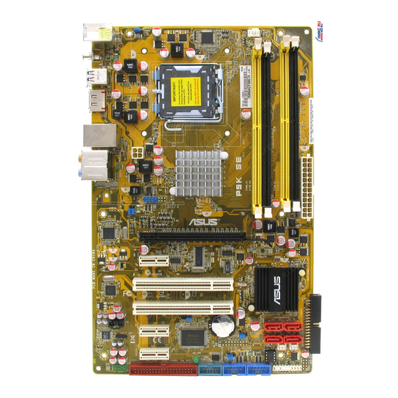
P5K SE/EPUMotherboard

E4039
Second Edition V2
June 2008
Copyright © 2008 ASUSTeK COMPUTER INC. All Rights Reserved.
No part of this manual, including the products and software described in it, may be reproduced, transmitted, transcribed, stored in a retrieval system, or translated into any language in any form or by any means, except documentation kept by the purchaser for backup purposes, without the express written permission of ASUSTeK COMPUTER INC. (“ASUS”).
Product warranty or service will not be extended if: (1) the product is repaired, modified or altered, unless such repair, modification of alteration is authorized in writing byASUS; or (2) the serial number of the product is defaced or missing.
ASUS PROVIDES THIS MANUAL “AS IS” WITHOUT WARRANTY OF ANY KIND, EITHER EXPRESS OR IMPLIED, INCLUDING BUT NOT LIMITED TO THE IMPLIED WARRANTIES OR CONDITIONS OF MERCHANTABILITY OR FITNESS FOR A PARTICULAR PURPOSE. IN NO EVENT SHALL ASUS, ITS DIRECTORS, OFFICERS, EMPLOYEES OR AGENTS BE LIABLE FOR ANY INDIRECT, SPECIAL, INCIDENTAL, OR CONSEQUENTIAL DAMAGES (INCLUDING DAMAGES FOR LOSS OF PROFITS, LOSS OF BUSINESS, LOSS OF USE OR DATA, INTERRUPTION OF BUSINESS AND THE LIKE), EVEN IF ASUS HAS BEEN ADVISED OF THE POSSIBILITY OF SUCH DAMAGES ARISING FROM ANY DEFECT OR ERROR IN THIS MANUAL OR PRODUCT.
SPECIFICATIONS AND INFORMATION CONTAINED IN THIS MANUAL ARE FURNISHED FOR INFORMATIONAL USE ONLY, AND ARE SUBJECT TO CHANGE AT ANY TIME WITHOUT NOTICE, AND SHOULD NOT BE CONSTRUED AS A COMMITMENT BY ASUS. ASUS ASSUMES NO RESPONSIBILITY OR LIABILITY FOR ANY ERRORS OR INACCURACIES THAT MAY APPEAR IN THIS MANUAL, INCLUDING THE PRODUCTS AND SOFTWARE DESCRIBED IN IT.
Products and corporate names appearing in this manual may or may not be registered trademarks or copyrights of their respective companies, and are used only for identification or explanation and to the owners’ benefit, without intent to infringe.
ii

Contents
|
Contents…………………………………………………………………………………………. |
iii |
|
Notices………………………………………………………………………………………….. |
vii |
|
Safety information…………………………………………………………………………. |
viii |
|
About this guide……………………………………………………………………………… |
ix |
|
P5K SE/EPU specifications summary………………………………………………. |
xi |
|
Chapter 1: |
Product introduction |
||
|
1.1 |
Welcome!…………………………………………………………………………… |
1-1 |
|
|
1.2 |
Package contents………………………………………………………………. |
1-1 |
|
|
1.3 |
Special features…………………………………………………………………. |
1-2 |
|
|
1.3.1 |
Product highlights…………………………………………………… |
1-2 |
|
|
1.3.2 |
ASUS AI Lifestyle features………………………………………. |
1-4 |
|
|
1.3.3 |
ASUS Stylish features.……………………………………………. |
1-5 |
|
|
1.3.4 |
ASUS Intelligent Overclocking features……………………… |
1-6 |
|
Chapter 2: |
Hardware information |
||
|
2.1 |
Before you proceed……………………………………………………………. |
2-1 |
|
|
2.2 |
Motherboard overview……………………………………………………….. |
2-2 |
|
|
2.2.1 |
Placement direction………………………………………………… |
2-2 |
|
|
2.2.2 |
Screw holes…………………………………………………………… |
2-2 |
|
|
2.2.3 |
Motherboard layout…………………………………………………. |
2-3 |
|
|
2.2.4 |
Layout contents.…………………………………………………….. |
2-4 |
|
|
2.3 |
Central Processing Unit (CPU)……………………………………………. |
2-6 |
|
|
2.3.1 |
Installing the CPU…………………………………………………… |
2-7 |
|
|
2.3.2 |
Installing the CPU heatsink and fan………………………….. |
2-9 |
|
|
2.3.3 |
Uninstalling the CPU heatsink and fan……………………… |
2-11 |
|
|
2.4 |
System memory……………………………………………………………….. |
2-13 |
|
|
2.4.1 |
Overview……………………………………………………………… |
2-13 |
|
|
2.4.2 |
Memory configurations.…………………………………………. |
2-14 |
|
|
2.4.3 |
Installing a DIMM………………………………………………….. |
2-18 |
|
|
2.4.4 |
Removing a DIMM………………………………………………… |
2-18 |
|
|
2.5 |
Expansion slots……………………………………………………………….. |
2-19 |
|
|
2.5.1 |
Installing an expansion card…………………………………… |
2-19 |
|
|
2.5.2 |
Configuring an expansion card……………………………….. |
2-19 |
|
|
2.5.3 |
Interrupt assignments……………………………………………. |
2-20 |
|
|
2.5.4 |
PCI slots.…………………………………………………………….. |
2-21 |
iii

Contents
|
2.5.5 |
PCI Express x1 slots …………………………………………….. |
2-21 |
|
|
2.5.6 |
PCI Express x16 slot . ……………………………………………. |
2-21 |
|
|
2.6 |
Jumpers |
…………………………………………………………………………… |
2-22 |
|
2.7 |
Connectors………………………………………………………………………. |
2-24 |
|
|
2.7.1 ………………………………………….. |
Rear panel connectors |
2-24 |
|
|
2.7.2 ……………………………………………….. |
Internal connectors |
2-26 |
|
Chapter 3: |
Powering up |
||
|
3.1 |
Starting up for the first time……………………………………………….. |
3-1 |
|
|
3.2 |
Turning off the computer……………………………………………………. |
3-2 |
|
|
3.2.1 |
Using the OS shut down function.…………………………….. |
3-2 |
|
|
3.2.2 |
Using the dual function power switch.……………………….. |
3-2 |
|
Chapter 4: |
BIOS setup |
||
|
4.1 |
Managing and updating your BIOS……………………………………… |
4-1 |
|
|
4.1.1 |
ASUS Update utility………………………………………………… |
4-1 |
|
|
4.1.2 |
Creating a bootable floppy disk.……………………………….. |
4-4 |
|
|
4.1.3 |
ASUS EZ Flash 2 utility.………………………………………….. |
4-5 |
|
|
4.1.4 |
AFUDOS utility………………………………………………………. |
4-6 |
|
|
4.1.5 |
ASUS CrashFree BIOS 3 utility………………………………… |
4-8 |
|
|
4.2 |
BIOS setup program…………………………………………………………… |
4-9 |
|
|
4.2.1 |
BIOS menu screen.………………………………………………. |
4-10 |
|
|
4.2.2 |
Menu bar…………………………………………………………….. |
4-10 |
|
|
4.2.3 |
Navigation keys.…………………………………………………… |
4-10 |
|
|
4.2.4 |
Menu items…………………………………………………………… |
4-11 |
|
|
4.2.5 |
Sub-menu items……………………………………………………. |
4-11 |
|
|
4.2.6 |
Configuration fields………………………………………………… |
4-11 |
|
|
4.2.7 |
Pop-up window……………………………………………………… |
4-11 |
|
|
4.2.8 |
Scroll bar……………………………………………………………… |
4-11 |
|
|
4.2.9 |
General help…………………………………………………………. |
4-11 |
|
|
4.3 |
Main menu……………………………………………………………………….. |
4-12 |
|
|
4.3.1 |
System Time………………………………………………………… |
4-12 |
|
|
4.3.2 |
System Date………………………………………………………… |
4-12 |
|
|
4.3.3 |
Legacy Diskette A…………………………………………………. |
4-12 |
|
|
4.3.4 |
SATA 1-4……………………………………………………………… |
4-13 |
|
|
4.3.5 |
SATAConfiguration……………………………………………….. |
4-14 |
|
|
4.3.6 |
System Information……………………………………………….. |
4-15 |
iv
Contents
|
4.4 |
Advanced menu……………………………………………………………….. |
4-16 |
|
|
4.4.1 |
Jumperfree Configuration………………………………………. |
4-16 |
|
|
4.4.2 |
AI NET 2……………………………………………………………… |
4-19 |
|
|
4.4.3 |
USB Configuration………………………………………………… |
4-20 |
|
|
4.4.4 |
CPU Configuration………………………………………………… |
4-21 |
|
|
4.4.5 |
Chipset……………………………………………………………….. |
4-22 |
|
|
4.4.6 |
OnBoard Devices Configuration……………………………… |
4-23 |
|
|
4.4.7 |
PCI PnP………………………………………………………………. |
4-24 |
|
|
4.5 |
Power menu…………………………………………………………………….. |
4-25 |
|
|
4.5.1 |
Suspend Mode…………………………………………………….. |
4-25 |
|
|
4.5.2 |
Repost Video on S3 Resume.………………………………… |
4-25 |
|
|
4.5.3 |
ACPI Version.………………………………………………………. |
4-25 |
|
|
4.5.4 |
ACPI APIC Support………………………………………………. |
4-25 |
|
|
4.5.5 |
APM Configuration……………………………………………….. |
4-26 |
|
|
4.5.6 |
Hardware Monitor…………………………………………………. |
4-27 |
|
|
4.6 |
Boot menu……………………………………………………………………….. |
4-29 |
|
|
4.6.1 |
Boot Device Priority………………………………………………. |
4-29 |
|
|
4.6.2 |
Boot Settings Configuration……………………………………. |
4-30 |
|
|
4.6.3 |
Security……………………………………………………………….. |
4-31 |
|
|
4.7 |
Tools menu………………………………………………………………………. |
4-33 |
|
|
4.7.1 |
ASUS EZ Flash 2…………………………………………………. |
4-33 |
|
|
4.7.2 |
ASUS O.C. Profile.……………………………………………….. |
4-34 |
|
|
4.8 |
Exit menu…………………………………………………………………………. |
4-35 |
|
Chapter 5: |
Software support |
||
|
5.1 |
Installing an operating system……………………………………………. |
5-1 |
|
|
5.2 |
Support CD information……………………………………………………… |
5-1 |
|
|
5.2.1 |
Running the support CD………………………………………….. |
5-1 |
|
|
5.2.2 |
Drivers menu.………………………………………………………… |
5-2 |
|
|
5.2.3 |
Utilities menu…………………………………………………………. |
5-3 |
|
|
5.2.4 |
Manual menu…………………………………………………………. |
5-5 |
|
|
5.2.5 |
ASUS Contact information……………………………………….. |
5-5 |
|
|
5.2.6 |
Other information……………………………………………………. |
5-6 |
|
|
5.3 |
Software information………………………………………………………….. |
5-8 |
|
|
5.3.1 |
ASUS MyLogo2™………………………………………………….. |
5-8 |
|
|
5.3.2 |
Audio configurations……………………………………………… |
5-10 |
|

Contents
|
5.3.3 |
ASUS PC Probe II.……………………………………………….. |
5-14 |
|
|
5.3.4 |
ASUS AI Suite……………………………………………………… |
5-20 |
|
|
5.3.5 |
ASUS EPU Utility — AI Gear 3+……………………………….. |
5-22 |
|
|
5.3.6 |
ASUS AI Nap……………………………………………………….. |
5-24 |
|
|
5.3.7 |
ASUS Q-Fan 2……………………………………………………… |
5-25 |
|
|
5.3.8 |
ASUS AI Booster.…………………………………………………. |
5-26 |
|
|
Appendix: |
CPU features |
||
|
A.1 |
Intel® EM64T………………………………………………………………………. |
A-1 |
|
|
A.2 |
Enhanced Intel SpeedStep® Technology (EIST)……………………. |
A-1 |
|
|
A.2.1 |
System requirements………………………………………………. |
A-1 |
|
|
A.2.2 |
Using the EIST……………………………………………………….. |
A-2 |
|
|
A.3 |
Intel® Hyper-Threading Technology…………………………………….. |
A-3 |
vi

Notices
Federal Communications Commission Statement
This device complies with Part 15 of the FCC Rules. Operation is subject to the following two conditions:
•This device may not cause harmful interference, and
•This device must accept any interference received including interference that may cause undesired operation.
This equipment has been tested and found to comply with the limits for a Class B digital device, pursuant to Part 15 of the FCC Rules. These limits are designed to provide reasonable protection against harmful interference in a residential installation. This equipment generates, uses and can radiate radio
frequency energy and, if not installed and used in accordance with manufacturer’s instructions, may cause harmful interference to radio communications. However, there is no guarantee that interference will not occur in a particular installation. If this equipment does cause harmful interference to radio or television reception, which can be determined by turning the equipment off and on, the user is encouraged to try to correct the interference by one or more of the following measures:
•Reorient or relocate the receiving antenna.
•Increase the separation between the equipment and receiver.
•Connect the equipment to an outlet on a circuit different from that to which the receiver is connected.
•Consult the dealer or an experienced radio/TV technician for help.
The use of shielded cables for connection of the monitor to the graphics card is required to assure compliance with FCC regulations. Changes or modifications to this unit not expressly approved by the party responsible for compliance could void the user’s authority to operate this equipment.
Canadian Department of Communications Statement
This digital apparatus does not exceed the Class B limits for radio noise emissions from digital apparatus set out in the Radio Interference Regulations of the Canadian Department of Communications.
This class B digital apparatus complies with Canadian ICES-003.
vii
Safety information
Electrical safety
•To prevent electrical shock hazard, disconnect the power cable from the electrical outlet before relocating the system.
•When adding or removing devices to or from the system, ensure that the power cables for the devices are unplugged before the signal cables are connected. If possible, disconnect all power cables from the existing system before you add a device.
•Before connecting or removing signal cables from the motherboard, ensure that all power cables are unplugged.
•Seek professional assistance before using an adpater or extension cord. These devices could interrupt the grounding circuit.
•Make sure that your power supply is set to the correct voltage in your area. If you are not sure about the voltage of the electrical outlet you are using, contact your local power company.
•If the power supply is broken, do not try to fix it by yourself. Contact a qualified service technician or your retailer.
Operation safety
•Before installing the motherboard and adding devices on it, carefully read all the manuals that came with the package.
•Before using the product, make sure all cables are correctly connected and the power cables are not damaged. If you detect any damage, contact your dealer immediately.
•To avoid short circuits, keep paper clips, screws, and staples away from connectors, slots, sockets and circuitry.
•Avoid dust, humidity, and temperature extremes. Do not place the product in any area where it may become wet.
•Place the product on a stable surface.
•If you encounter technical problems with the product, contact a qualified service technician or your retailer.
This symbol of the crossed out wheeled bin indicates that the product (electrical, electronic equipment, and mercury-containing button cell battery) should not
be placed in municipal waste. Check local regulations for disposal of electronic products.
viii

About this guide
This user guide contains the information you need when installing and configuring the motherboard.
How this guide is organized
This guide contains the following parts:
•Chapter 1: Product introduction
This chapter describes the features of the motherboard and the new technology it supports.
•Chapter 2: Hardware information
This chapter lists the hardware setup procedures that you have to perform when installing system components. It includes description of the switches, jumpers, and connectors on the motherboard.
•Chapter 3: Powering up
This chapter describes the power up sequence and ways of shutting down the system.
•Chapter 4: BIOS setup
This chapter tells how to change system settings through the BIOS Setup menus. Detailed descriptions of the BIOS parameters are also provided.
•Chapter 5: Software support
This chapter describes the contents of the support CD that comes with the motherboard package.
•Appendix: CPU features
The Appendix describes the CPU features and technologies that the motherboard supports.
Where to find more information
Refer to the following sources for additional information and for product and software updates.
1.ASUS websites
The ASUS website provides updated information on ASUS hardware and software products. Refer to the ASUS contact information.
2.Optional documentation
Your product package may include optional documentation, such as warranty flyers, that may have been added by your dealer. These documents are not part of the standard package.
ix

Conventions used in this guide
To make sure that you perform certain tasks properly, take note of the following symbols used throughout this manual.
DANGER/WARNING: Information to prevent injury to yourself when trying to complete a task.
CAUTION: Information to prevent damage to the components when trying to complete a task.
IMPORTANT: Instructions that you MUST follow to complete a task.
NOTE: Tips and additional information to help you complete a task.
Typography
|
Bold text |
Indicates a menu or an item to select. |
|
Italics |
Used to emphasize a word or a phrase. |
|
<Key> |
Keys enclosed in the less-than and greater-than sign |
|
means that you must press the enclosed key. |
Example: <Enter> means that you must press the Enter or Return key.
<Key1>+<Key2>+<Key3> If you must press two or more keys simultaneously, the key names are connected with a plus sign (+).
Example: <Ctrl>+<Alt>+<D>
Command Means that you must type the command exactly as shown.
Example: At the DOS prompt, type the command line:
afudos /iP5KSE.ROM
![]()
P5K SE/EPU specifications summary
CPU
Chipset
System bus
Memory
Expansion slots
Storage
LAN
Audio
USB
AI Lifestyle Unique features
Other features
LGA775 socket for Intel® Core™2 Extreme / Core™2 Quad / Core™2 Duo / Pentium® Extreme / Pentium® D / Pentium® 4 processors
Compatible with Intel® 05B/05A/06 processors Supports Intel® next-generation 45nm multi-core CPU
Intel® P35 / ICH9 with Intel® Fast Memory Access Technology
1600/1333/1066/800 MHz
Dual-channel memory architecture
— 4 x 240-pin DIMM sockets support unbuffered non-ECC DDR2 1200/1066/800/667MHz memory modules
— Supports up to 8 GB system memory
* Refer to www.asus.com or this user manual for the
Memory QVL (Qualified Vendors Lists).
1 x PCI Express™ x16 slot
3 x PCI Express™ x1 slots
2 x PCI slots
Southbridge
— 4 x Serial ATA 3.0 Gb/s ports
Marvell® 88SE6111 PATA and SATA controller supports: — 1 x UltraDMA 133/100/66 for up to 2 PATA devices — 1 x External SATA 3.0 Gb/s port (SATA On-the-Go)
PCIe Gigabit LAN controller featuring AI NET2
Realtek® ALC883 8-channel High-DefinitionAudio CODEC
— Supports Jack-Sensing, Multi-Streaming — Coaxial S/PDIF out ports at back I/O
— ASUS Noise Filter
12 x USB 2.0 ports (6 at mid-board, 6 at back panel)
ASUS Power Saving Solution:
— ASUS EPU (Energy Processing Unit)
— ASUS AI Nap
— ASUS Q-Fan 2
ASUS Crystal Sound:
— ASUS Noise Filter
ASUS EZ DIY:
— ASUS Q-Connector
— ASUS O.C. Profile
— ASUS CrashFree BIOS 3
— ASUS EZ Flash 2
ASUS MyLogo2
(continued on the next page)
xi

P5K SE/EPU specifications summary
ASUS Exclusive Overclocking features
Rear panel connectors
Internal connectors
BIOS features
Manageability
Support CD contents
Form factor
Intelligent overclocking tools: — ASUS AI Booster utility
Precision Tweaker:
— vCore: Adjustable CPU voltage at 0.0125V increment
— vDIMM: 17-step DRAM voltage control SFS (Stepless Frequency Selection):
— FSB tuning from 200MHz to 800 MHz at 1MHz increment
— Memory tuning from 667MHz to 1333MHz for DDR2 — PCI-E frequency tuning from 100MHz to 150MHz at
1 MHz increment
Overclocking protection:
— ASUS C.P.R. (CPU Parameter Recall)
1 x PS/2 keyboard port
1 x External Serial ATA port
1 x Coaxial S/PDIF Out port
1 x LAN (RJ-45) port
6 x USB 2.0/1.1 ports
8-channel audio ports
3 x USB connectors support 6 additional USB ports
1 x Floppy disk drive connector
1 x IDE connector
4 x Serial ATA connectors
1 x CPU / 1 x Chassis / 1 x Power fan connectors 1 x COM connector
1 x S/PDIF Out header Chassis intrusion connector Front panel audio connector CD audio in connector 24-pin ATX power connector
4-pin ATX 12V power connector System panel connector (Q-Connector)
8 Mb Flash ROM, AMI BIOS, PnP, DMI 2.0, WfM 2.0, SM BIOS 2.3, ACPI 2.0a, ASUS EZ Flash 2, ASUS CrashFree BIOS 3
WfM 2.0, DMI 2.0, WOL by PME, WOR by PME, PXE
Drivers
ASUS PC Probe II
ASUS Update
ASUS AI Suite
Anti-virus software (OEM version)
ATX form factor: 12 in x 7.6 in (30.5 cm x 19.3 cm)
*Specifications are subject to change without notice.
xii
|
This chapter describes the motherboard |
1 |
|
features and the new technologies |
|
|
it supports. |
|
|
Chapter 1: |
Product |
|
introduction |

|
1.1 |
Welcome!…………………………………………………………………………… |
1-1 |
|
1.2 |
Package contents………………………………………………………………. |
1-1 |
|
1.3 |
Special features…………………………………………………………………. |
1-2 |
ASUS P5K SE/EPU

1.1Welcome!
Thank you for buying an ASUS® P5K SE/EPU motherboard!
The motherboard delivers a host of new features and latest technologies, making it another standout in the long line of ASUS quality motherboards!
Before you start installing the motherboard, and hardware devices on it, check the items in your package with the list below.
1.2Package contents
Check your motherboard package for the following items.
|
Motherboard |
ASUS P5K SE/EPU |
|
Cables |
2 x Serial ATA signal cable |
|
1 x Serial ATA power cable |
|
|
1 x Ultra DMA 133/100/66 cable |
|
|
1 x Floppy disk drive cable |
|
|
Accessories |
I/O shield |
|
1 xASUS Q-Connector Kit (USB, system panel; |
|
|
Retail version only) |
|
|
Application CD |
ASUS motherboard support CD |
|
ASUS Superb Software Library CD |
|
|
Documentation |
User guide |
If any of the above items is damaged or missing, contact your retailer.
1.3Special features
1.3.1Product highlights
Green ASUS
This motherboard and its packaging comply with the European Union’s Restriction on the use of Hazardous Substances (RoHS). This is in line with theASUS vision of creating environment-friendly and recyclable products/packaging to safeguard consumers’ health while minimizing the impact on the environment.
Supports
Intel® Quad-core Processor Ready
This motherboard supports the latest Intel® Quad-core processors in the LGA775 package and Intel’s next-generation 45nm multi-core processors. It is excellent for multi-tasking, multi-media and enthusiastic gamers with 1600/1333/1066/800 MHz
FSB. Intel® Quad-core processor is one of the most powerful CPU in the world. See page 26 for details.
Intel® Core™2 Duo/ Intel® Core™2 Extreme CPU support
This motherboard supports the latest Intel® Core™2 processor in the LGA775 package and Intel’s next-generation 45nm multi-core processors. With the new Intel® Core™ microarchitecture technology and 1600/1333/1066/800 MHz FSB, the Intel® Core™2 is one of the most powerful and energy efficient CPUs in the world.
See page 26 for details.
Intel P35 Chipset 
The Intel® P35 Express Chipset is the latest chipset designed to support the next generation 45nm CPU and up to 8GB of dual-channel DDR2 800/677 MHz
memory architecture. It also supports 1600/1333/1066/800 FSB (Front Side Bus), PCI Express x16 graphics and multi-core CPUs.
ASUS Super Memspeed Technology
To attain top performance, ASUS has managed to break through current FSB and DRAM ratio proportions by utilizing Super Memspeed Technology–the latest technology that provides even more precise overclocking options to unleash the true potential of DDR2 memory. The DDR2 Mode maximizes system performance by eliminating the bottleneck when overclocking both the CPU and memory– providing great performance for 3D graphics and other memory demanding applications. See page 213 for details.
|
1-2 |
Chapter 1: Product Introduction |

Serial ATA 3.0 Gb/s technology and SATA-On-The-Go 
This motherboard supports the next-generation hard drives based on the Serial
ATA(SATA) 3Gb/s storage specification, delivering enhanced scalability and doubling the bus bandwidth for high-speed data retrieval and saves. The external SATA port located at the back I/O provides smart setup and hot-plug functions. Easily backup photos, videos and other entertainment contents to external devices. See pages 2-25 and 2-28 for details.
S/PDIF digital sound ready 
This motherboard provides convenient connectivity to external home theater audio systems via coaxial and optical S/PDIF-out (SONY-PHILIPS Digital Interface) jacks.It allows to transfer digital audio without converting to analog format and keeps the best signal quality. See pages 2-25 and 2-29 for details.
High Definition Audio 
Enjoy high-end sound quality on your PC! The onboard 8-channel High Definition Audio CODEC enables high-quality 192KHz/24-bit audio output, jack-sensing feature, and multi-streaming technology that simultaneously sends different audio streams to different destinations. You can now talk to your partners on the headphone while playing multi-channel network games. See pages 2-24 and 2-25 for details.

1.3.2 ASUS AI Lifestyle features
ASUS Power Saving Solution
ASUS Power Saving solution makes system more stable and enhances the overclocking capability.
ASUS EPU 
TheASUS EPU utilizes innovative technology to digitally monitor and tune the CPU power supply with improved VR responses in heavy or light loadings. It automatically provides power for higher performance or improve
efficiency by 50% when the PC is running low intensity applications. Working together with AI Gear 3+, this can help you attain the best possible power efficiency and energy savings up to 80.23% to help save the environment.
See page 5-22 for details.
AI Nap 
With AI Nap, the system can continue running at minimum power and noise when you are temporarily away. To wake the system and return to the OS environment, simply click the mouse or press a key. See page 5-24 for details.
Q-Fan 2 
ASUS Q-Fan2 technology intelligently adjusts both CPU fan and chassis fan speedsaccordingtosystemloadingtoensurequiet,coolandefficientoperation.
See page 4-27,4-28 and 5-25 for details.
ASUS Crystal Sound
This feature can enhance speech-centric applications like Skype, online game, video conference and recording.
Noise Filter 
This feature detects repetitive and stationary noises (non-voice signals) like computer fans, air conditioners, and other background noises then eliminates it in the incoming audio stream while recording.
|
1-4 |
Chapter 1: Product Introduction |

ASUS EZ DIY
ASUS EZ DIY feature collection provides you easy ways to install computer components, update the BIOS or back up your favorite settings.
ASUS Q-Connector 
ASUS Q-Connector allows you to easily connect or disconnect the chassis front panel cables to the motherboard. This unique module eliminates the trouble of connecting the system panel cables one at a time and avoiding wrong cable connections. See page 2-35 for details.
ASUS O.C. Profile 
The motherboard features theASUS O.C. Profile that allows users to conveniently store or load multiple BIOS settings. The BIOS settings can be stored in the CMOS or a separate file, giving users freedom to share and distribute their favorite settings. See page 4-34 for details.
ASUS CrashFree BIOS 3 
The ASUS CrashFree BIOS 3 allows users to restore corrupted BIOS data from a USB flash disk containing the BIOS file. See page 4-8 for details.
ASUS EZ Flash 2 
EZ Flash 2 is a user-friendly BIOS update utility. Simply press the predefined hotkey to launch the utility and update the BIOS without entering the OS. Update your BIOS easily without preparing a bootable diskette or using an
OS-based flash utility. See page 4-5 and 4-33 for details.
Smart Support CD
It provides a checklist to allow the user to see which drivers are already installed, as well as those that aren’t. When using ASUS PC Probe II, you can easily see the critical parts of the computer.
1.3.3ASUS Stylish features
ASUS MyLogo2™
This feature allows you to convert your favorite photo into a 256-color boot logo for a more colorful and vivid image on your screen. See pages 5-8 and 5-9 for details.

1.3.4ASUS Intelligent Overclocking features
AI Booster
The ASUS AI Booster allows you to overclock the CPU speed in Windows environment without the hassle of booting the BIOS. See page 5-26 for details.
Precision Tweaker
This feature allows you to fine tune the CPU/memory voltage and gradually increase the memory Front Side Bus (FSB) and PCI Express frequency at 1MHz increment to achieve maximum system performance. See page 4-17 to 4-19 for details.
C.P.R. (CPU Parameter Recall)
The C.P.R. feature of the motherboard BIOS allows automatic re-setting to the BIOS default settings in case the system hangs due to overclocking. When the system hangs due to overclocking, C.P.R. eliminates the need to open the system chassis and clear the RTC data. Simply shut down and reboot the system, and the BIOS automatically restores the CPU default setting for each parameter.
|
1-6 |
Chapter 1: Product Introduction |
This chapter lists the hardware setup procedures that you have to perform when installing system components. It includes description of the jumpers and connectors on the motherboard.
Chapter 2:
Hardware2 information

|
2.1 |
Before you proceed……………………………………………………………. |
2-1 |
|
2.2 |
Motherboard overview……………………………………………………….. |
2-2 |
|
2.3 |
Central Processing Unit (CPU)……………………………………………. |
2-6 |
|
2.4 |
System memory……………………………………………………………….. |
2-13 |
|
2.5 |
Expansion slots……………………………………………………………….. |
2-19 |
|
2.6 |
Jumpers…………………………………………………………………………… |
2-22 |
|
2.7 |
Connectors………………………………………………………………………. |
2-24 |
ASUS P5K SE/EPU

2.1Before you proceed
Take note of the following precautions before you install motherboard components or change any motherboard settings.
•Unplug the power cord from the wall socket before touching any component.
•Use a grounded wrist strap or touch a safely grounded object or a metal object, such as the power supply case, before handling components to avoid damaging them due to static electricity.
•Hold components by the edges to avoid touching the ICs on them.
•Whenever you uninstall any component, place it on a grounded antistatic pad or in the bag that came with the component.
•Before you install or remove any component, ensure that the ATX power supply is switched off or the power cord is detached from the power supply. Failure to do so may cause severe damage to the motherboard, peripherals, and/or components.
Onboard LED
The motherboard comes with a standby power LED that lights up to indicate that the system is ON, in sleep mode, or in soft-off mode. This is a reminder that you should shut down the system and unplug the power cable before removing or plugging in any motherboard component. The illustration below shows the location of the onboard LED.
P5K SE/EPU
SB_PWR
|
ON |
OFF |
|
Standby |
Powered |
|
Power |
Off |
P5K SE/EPU Onboard LED

2.2Motherboard overview
Before you install the motherboard, study the configuration of your chassis to ensure that the motherboard fits into it.
Make sure to unplug the power cord before installing or removing the motherboard. Failure to do so can cause you physical injury and damage motherboard components.
2.2.1Placement direction
When installing the motherboard, make sure that you place it into the chassis in the correct orientation. The edge with external ports goes to the rear part of the chassis as indicated in the image below.
2.2.2Screw holes
Place six (6) screws into the holes indicated by circles to secure the motherboard to the chassis.
Do not overtighten the screws! Doing so can damage the motherboard.
Place this side towards the rear of the chassis
P5K SE/EPU

 ®
®
|
2-2 |
Chapter 2: Hardware information |
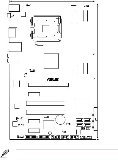
2.2.3Motherboard layout
19.3cm (7.6in)
KB_USB56 PS2_USBPW
SPDIF_O1 ATX12V
LGA775
USB34
ESATA
LAN1_USB12
|
AUDIO |
Intel® |
|
|
P35 |
||
|
4- |
||
|
SUBPW1 USBPW78 |
USB78 |
|
|
® |
||
|
AttansIc |
PCIEX16_1 |
|
|
L1 |
EPU CPU_FAN 


|
DDR2 DIMM B1 (64 bit,240-pin module) |
DDR2 DIMM B2 (64 bit,240-pin module) |
||||||||||
|
P5K SE/EPU |
_ |
DDR2 DIMM A1 (64 bit,240-pin module) |
_ |
DDR2 DIMM A2 (64 bit,240-pin module) |
_ |
_ |
|||||
|
EATXPWR |
(12.0in) |
||||||||||
|
30.5cm |
|||||||||||
PCIEX1_3
|
Marvell |
PCI1 |
Intel® |
|
88SE6111 |
ICH9 |
|
|
PCI2 |
 FLOPPY
|
CD |
CR2032 3V |
SATA4 |
SATA3 |
||||
|
CHASSIS |
|||||||
|
PCIEX1_1 |
Lithium Cell |
||||||
|
ALC883 |
Super |
CMOS Power |
SATA2 |
SATA1 |
|||
|
SPDIF_OUT |
|||||||
|
CLRTC |
|||||||
|
I/O |
PWR_FAN |
||||||
|
PCIEX1_2 |
|||||||
|
SB_PWR |
USBPW9-12 |
BIOS |
CHA_FAN |
||||
|
AAFP |
PRI_EIDE |
COM1 |
USB1112 USB910 |
PANEL |
|||
Refer to 2.7 Connectors for more information about rear panel connectors and internal connectors.
2.2.4Layout contents
|
Slots |
Page |
|
|
1. |
DDR2 DIMM slots |
2-13 |
|
2. |
PCI slots |
2-21 |
|
3 |
PCI Express x1 slot |
2-21 |
|
4. |
PCI Express x16 slots |
2-21 |
|
Jumper |
Page |
|
|
1. |
Clear RTC RAM (3-pin CLRTC) |
2-22 |
|
2. |
Keyboard power (3-pin PS2_USBPW) |
2-23 |
|
3. |
USB device wake-up (3-pin USBPW1-4, USBPW5-8, USB9-12) |
2-23 |
|
Rear panel connectors |
Page |
|
|
1. |
PS/2 keyboard port (purple) |
2-24 |
|
2. |
LAN (RJ-45) port |
2-24 |
|
3. |
Center/Subwoofer port (orange) |
2-24 |
|
4. |
Rear Speaker Out port (black) |
2-24 |
|
5. |
Line In port (light blue) |
2-24 |
|
6. |
Line Out port (lime) |
2-24 |
|
7. |
Microphone port (pink) |
2-24 |
|
8. |
Side Speaker Out port (gray) |
2-24 |
|
9. |
USB 2.0 ports 1 and 2 |
2-24 |
|
10. |
External SATA port |
2-25 |
|
11. |
USB 2.0 ports 3 and 4 |
2-25 |
|
12. |
Coaxial S/PDIF Out port |
2-25 |
|
13. |
USB 2.0 ports 5 and 6 |
2-25 |
|
2-4 |
Chapter 2: Hardware information |

|
Internal connectors |
Page |
||
|
1. |
Floppy disk drive connector (34-1 pin FLOPPY) |
2-26 |
|
|
2. |
IDE connector (40-1 pin PRI_EIDE) |
2-27 |
|
|
3. |
ICH9 Serial ATA connectors (7-pin SATA1-4) |
2-28 |
|
|
4. |
Digital audio connector (4-1 pin SPDIF_OUT) |
2-29 |
|
|
5. |
USB connectors (10-1 pin USB78, USB910, USB1112) |
2-30 |
|
|
6. |
Optical drive audio connector (4-pin CD) |
2-30 |
|
|
7. |
CPU, chassis, and power fan connectors |
2-31 |
|
|
(4-pin CPU FAN, 3-pin CHA_FAN, 3-pin PWR_FAN) |
|||
|
8. |
Serial port connector (10-1 pin COM1) |
2-31 |
|
|
9. |
Chassis intrusion connector (4-1 pin CHASSIS) |
2-32 |
|
|
10. |
Front panel connector (10-1 pin AAFP) |
2-32 |
|
|
11. |
ATX power connectors (24-pin EATXPWR, 4-pin EATX12V) |
2-33 |
|
|
12. |
System panel connector (20-8-pin PANEL) |
2-34 |
|
|
• |
System power LED (2-pin PLED) |
||
|
• |
Hard disk drive activity LED (2-pin IDE_LED) |
||
|
• |
System warning speaker (4-pin SPEAKER) |
||
|
• |
ATX power button/soft-off button (2-pin PWRSW) |
||
|
• |
Reset button (2-pin RESET) |
||
|
ASUS Q-connector (system panel) |
2-35 |
2.3Central Processing Unit (CPU)
The motherboard comes with a surface mount LGA775 socket designed for the Intel® Core™2 Quad / Core™2 Extreme / Core™2 Duo / Pentium® Extreme / Pentium® D / Pentium® 4 processors.
• Make sure that all power cables are unplugged before installing the CPU.
• Connect the chassis fan cable to the CHA_FAN1 connector to ensure system stability.
• Upon purchase of the motherboard, make sure that the PnP cap is on the socket and the socket contacts are not bent. Contact your retailer
immediately if the PnP cap is missing, or if you see any damage to the PnP cap/socket contacts/motherboard components. ASUS will shoulder the cost of repair only if the damage is shipment/transit-related.
•Keep the cap after installing the motherboard. ASUS will process Return
MerchandiseAuthorization (RMA) requests only if the motherboard comes with the cap on the LGA775 socket.
•The product warranty does not cover damage to the socket contacts resulting from incorrect CPU installation/removal, or misplacement/loss/ incorrect removal of the PnP cap.
|
2-6 |
Chapter 2: Hardware information |

2.3.1Installing the CPU
To install a CPU:
1.Locate the CPU socket on the motherboard.
P5K SE/EPU
P5K SE/EPU CPU Socket 775
Before installing the CPU, make sure that the socket box is facing towards you and the load lever is on your left.
2.Press the load lever with your thumb (A), then move it to the left (B) until it is released from the retention tab.
|
Retention tab |
A |
PnP cap |
|||||
|
Load lever |
|||||||
|
B |
|||||||
|
This side of the socket box |
|||||||
|
should face you. |
To prevent damage to the socket pins, do not remove the PnP cap unless you are installing a CPU.
3.Lift the load lever in the direction of the arrow to a 135º angle.
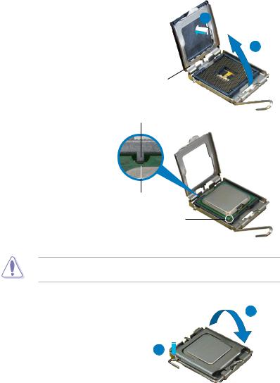
4.Lift the load plate with your thumb and forefinger to a 100º angle (A), then push the PnP cap from the load plate window to remove (B).
Alignment key
5.Position the CPU over the socket, making sure that the gold triangle is on the bottom left corner of the socket then fit the socket alignment key into the CPU notch.
CPU notch
Gold triangle mark
The CPU fits in only one correct orientation. DO NOT force the CPU into the socket to prevent bending the connectors on the socket and damaging the CPU!
|
6. |
Close the load plate (A), then |
A |
|
push the load lever (B) until it |
||
|
snaps into the retention tab. |
||
|
7. |
If installing a dual-core CPU, |
B |
|
connect the chassis fan cable |
||
|
to the CHA_FAN1 connector to |
||
|
ensure system stability. |
|
2-8 |
Chapter 2: Hardware information |
![]()
2.3.2Installing the CPU heatsink and fan
The Intel® LGA775 processor requires a specially designed heatsink and fan assembly to ensure optimum thermal condition and performance.
• When you buy a boxed Intel® processor, the package includes the CPU fan and heatsink assembly. If you buy a CPU separately, make sure that you use only Intel® certified multi directional heatsink and fan.
•Your Intel® LGA775 heatsink and fan assembly comes in a push-pin design and requires no tool to install.
•If you purchased a separate CPU heatsink and fan assembly, make sure that you have properly applied Thermal Interface Material to the CPU heatsink or CPU before you install the heatsink and fan assembly.
Make sure that you have installed the motherboard to the chassis before you install the CPU fan and heatsink assembly.
To install the CPU heatsink and fan:
1.Place the heatsink on top of the installed CPU, making sure that the four fasteners match the holes on the motherboard.
Orient the heatsink and fan assembly such that the CPU fan cable is closest to the CPU fan connector.
|
Motherboard hole |
||||||
|
Narrow end |
Fastener |
|||||
|
of the groove |
Make sure to orient each fastener with the narrow end of the groove pointing outward. (The photo shows the groove shaded for emphasis.)

|
2. Push down two fasteners at a time in |
|||||
|
a diagonal sequence to secure the |
B |
||||
|
heatsink and fan assembly in place. |
|||||
|
A |
|||||
|
A |
B |
B |
|||
|
B |
A |
||||
A
3.Connect the CPU fan cable to the connector on the motherboard labeled CPU_FAN.
P5K SE/EPU

 CPU_FAN
GNDCPUCPUCPU
PWR FANIN FANPWM FAN
P5K SE/EPU CPU fan connector
Do not forget to connect the CPU fan connector! Hardware monitoring errors can occur if you fail to plug this connector.
|
2-10 |
Chapter 2: Hardware information |

2.3.3Uninstalling the CPU heatsink and fan
To uninstall the CPU heatsink and fan:
1.Disconnect the CPU fan cable from the connector on the motherboard.
2.Rotate each fastener counterclockwise.
3.Pull up two fasteners at a time in a diagonal sequence to disengage the heatsink and fan assembly from the motherboard.
4.Carefully remove the heatsink and fan assembly from the motherboard.

5.Rotate each fastener clockwise to ensure correct orientation when reinstalling.
The narrow end of the groove should point outward after resetting. (The photo shows the groove shaded for emphasis.)
Narrow end of the groove
Refer to the documentation in the boxed or stand-alone CPU fan package for detailed information on CPU fan installation.
|
2-12 |
Chapter 2: Hardware information |

2.4System memory
2.4.1Overview
The motherboard comes with four Double Data Rate 2 (DDR2) Dual Inline Memory Modules (DIMM) sockets.
The figure illustrates the location of the DDR2 DIMM sockets:
P5K SE/EPU
|
DIMM A1 DIMM A2 |
DIMM B1 DIMM B2 |
||||||||||||||||||||
P5K SE/EPU 240-pin DDR2 DIMM sockets
|
Channel |
Sockets |
|
Channel A |
DIMM_A1 and DIMM_B1 |
|
Channel B |
DIMM_A2 and DIMM_B2 |

2.4.2Memory configurations
You may install 256 MB, 512 MB, 1 GB, and 2 GB unbuffered non ECC DDR2 DIMMs into the DIMM sockets.
Recommended Memory Configurations
|
Mode |
Sockets |
||||
|
DIMM_A1 |
DIMM_A2 |
DIMM_B1 |
DIMM_B2 |
||
|
Single-Channel |
— |
— |
Populated |
— |
|
|
Populated |
— |
— |
— |
||
|
Dual-channel (1) |
Populated |
— |
Populated |
— |
|
|
Dual-channel (2) |
Populated |
Populated |
Populated |
Populated |
• You may install varying memory sizes in ChannelAand Channel B. The system maps the total size of the lower-sized channel for the dual-channel configuration.Any excess memory from the higher-sized channel is then mapped for single-channel operation.
•Always install DIMMs with the same CAS latency. For optimum compatibility, it is recommended that you obtain memory modules from the same vendor.
•If you install four 1 GB memory modules, the system may only recognize less than 3GB because the address space is reserved for other critical functions. This limitation appears on Windows® XP/Vista 32-bit operation system which does not support Physical Address Extension (PAE).
•If you install Windows® XP/Vista 32-bit operation system, a total memory of less than 3GB is recommended.
•This motherboard does not support memory modules made up of 128 Mb chips.
Notes on memory limitations
• Due to chipset limitation, this motherboard can only support up to
8 GB on the operating systems listed below. You may install a maximum of 2 GB DIMMs on each slot.
64-bit
Windows® XP Professional x64 Edition
Windows® Vista x64 Edition
•Some old-version DDR2-800 DIMMs may not match Intel®’s On Die Termination (ODT) requirement and will automatically downgrade to run at DDR2-667. If this happens, contact your memory vendor to check the ODT value.
•Due to chipset limitation, DDR2-800 with CL=4 will be downgraded to run at DDR2-667 by default setting. If you want to operate with lower latency, adjust the memory timing manually.
|
2-14 |
Chapter 2: Hardware information |

P5K SE/EPU Motherboard Qualified Vendors Lists (QVL)
DDR2-1066 MHz capability
|
Size |
Vendor |
SS/ |
Part No. |
DIMM support |
|||
|
DS |
A* |
B* |
C* |
||||
|
512 |
OCZ |
DS |
OCZ2P10002GK / PC2 8000 / 1G EL Dual CH / Platinum |
• |
• |
||
|
XTC |
|||||||
|
512 |
Crucial |
SS |
BL646AA1005.8FD / CL111R5W6-65183 |
• |
|||
|
512 |
Kingston |
SS |
KHX8500D2 / 512 / 9905315 — 028.AOOLF / 2297056 2.2V |
• |
|||
|
1024 |
Kingston |
DS |
KHX8000D2 / 1G / 9905316 — 028.AOOLF / 2310576 2.2V |
• |
• |
||
|
1024 |
CORSAIR |
DS |
CM2X1024-8500C5D 1024MB / XMS8505v1.2 / |
• |
|||
|
0648081-1 |
|||||||
|
1024 |
CORSAIR |
DS |
CM21024-8500-C5 / XMS8505v1.1 / 0616126-12 |
• |
• |
• |
|
|
1024 |
OCZ |
DS |
OCZ2TA1000VX22GK / PC2 8000 / 1GB Dual CH / Titanium |
• |
|||
|
Alpha VX2 |
|||||||
|
1024 |
Kingston |
DS |
KHX8500D2K2 / 2GN / 9905316 — 071.AOOLF K2 / |
• |
|||
|
2733866 |
2.2V |
||||||
|
1024 |
CORSAIR |
DS |
CM2X1024 — 9136C5D / XMS9105V1.1 |
• |
If you install a DDR2-1066 memory module whose SPD is DDR2-800, make sure that you set the DRAM Frequency item in BIOS to [DDR2-1066MHz]. See section 4.4.1 Jumperfree Configuration for details.

P5K SE/EPU Motherboard Qualified Vendors Lists (QVL)
DDR2-800 MHz capability
|
Size |
Vendor |
Chip No. |
CL |
Chip |
SS/ |
Part No. |
DIMM support |
|||
|
Brand |
DS |
A* |
B* |
C* |
||||||
|
512MB |
KINGSTON |
K4T51083QC |
5 |
SEC |
SS |
KVR800D2N5/512 |
• |
• |
• |
|
|
1024MB |
KINGSTON |
Heat-Sink Package |
4-4-4-12 |
N/A |
DS |
KHX6400D2LL/1G |
• |
• |
||
|
1024MB |
KINGSTON |
Heat-Sink Package |
4-4-4-12 |
N/A |
SS |
KHX6400D2LLK2/1GN |
• |
• |
• |
|
|
1024MB |
KINGSTON |
V59C1512804QBF25 |
N/A |
N/A |
DS |
KVR800D2N5/1G |
• |
• |
||
|
256MB |
Qimonda |
HYB18T512160BF-25F |
5-5-5 |
INFINEON |
SS |
HYS64T32000HU-25F-B |
• |
• |
||
|
512MB |
Qimonda |
HYB18T512800BF25F |
5-5-5 |
N/A |
SS |
HYS64T64000HU-25F-B |
• |
• |
• |
|
|
1024MB |
Qimonda |
HYB18T512800BF25F |
5-5-5 |
N/A |
DS |
HYS64T128020HU-25F-B |
• |
• |
||
|
512MB |
SAMSUNG |
EDD339XX |
5-5-5 |
N/A |
SS |
M378T6553CZ3-CE7 |
• |
• |
• |
|
|
256MB |
SAMSUNG |
K4T51163QC-ZCE7 |
5-5-5 |
SAMSUNG |
SS |
M378T3354CZ3-CE7 |
• |
• |
• |
|
|
512MB |
SAMSUNG |
ZCE7K4T51083QC |
5-5-5 |
SEC |
SS |
M378T6553CZ3-CE7 |
• |
• |
• |
|
|
512MB |
Hynix |
HY5PS12821CFP-S5 |
5-5-5 |
Hynix |
SS |
HYMP564U64CP8-S5 |
• |
• |
• |
|
|
512MB |
MICRON |
D9GKX |
N/A |
N/A |
SS |
MT8HTF6464AY-80ED4 |
• |
• |
• |
|
|
1024MB |
MICRON |
D9GKX |
N/A |
N/A |
DS |
MT16HTF12864AY-80ED4 |
• |
• |
||
|
1024MB |
CORSAIR |
Heat-Sink Package |
4 |
N/A |
DS |
CM2X1024-6400C4 |
• |
|||
|
512MB |
Crucial |
Heat-Sink Package |
4 |
N/A |
SS |
BL6464AA804.8FD |
• |
• |
• |
|
|
1024MB |
Crucial |
Heat-Sink Package |
4 |
N/A |
DS |
BL12864AA804.16FD |
• |
• |
||
|
1024MB |
Crucial |
Heat-Sink Package |
4 |
N/A |
DS |
BL12864AL804.16FD3 |
• |
• |
||
|
1024MB |
Crucial |
Heat-Sink Package |
4 |
N/A |
DS |
BL12864AA804.16FD3 |
• |
• |
• |
|
|
512MB |
Apacer |
Heat-Sink Package |
5 |
N/A |
DS |
AHU512E800C5K1C |
• |
• |
||
|
1024MB |
Apacer |
Heat-Sink Package |
5 |
N/A |
DS |
AHU01GE800C5K1C |
• |
• |
• |
|
|
512MB |
A-DATA |
AD29608A8A-25EG |
N/A |
N/A |
SS |
M2OAD6G3H3160G1E53 |
• |
• |
• |
|
|
1024MB |
A-DATA |
AD26908A8A-25EG |
N/A |
N/A |
DS |
M2OAD6G3I4170I1E58 |
• |
• |
||
|
512MB |
KINGMAX |
KKA8FEIBF-HJK-25A |
N/A |
KINGMAX |
SS |
KLDC28F-A8KI5 |
• |
• |
• |
|
|
1024MB |
KINGMAX |
KKA8FEIBF-HJK-25A |
N/A |
KINGMAX |
DS |
KLDD48F-ABKI5 |
• |
• |
• |
|
|
512MB |
Transcend |
HY5PS12821CFP-S5 |
N/A |
Hynix |
SS |
TS64MLQ64V8J |
• |
• |
• |
|
|
1024MB |
Transcend |
HY5PS12821CFP-S5 |
N/A |
Hynix |
DS |
TS128MLQ64V8J |
• |
• |
||
|
512MB |
Super |
Heat-Sink Package |
N/A |
N/A |
SS |
T800UA12C4 |
• |
• |
• |
|
|
Talent |
||||||||||
|
512MB |
NANYA |
NT5TU64M8BE-25C |
5 |
NANYA |
SS |
NT512T64U880BY-25C |
• |
• |
• |
|
|
1024MB |
NANYA |
NT5TU64M8BE-25C |
5 |
NANYA |
DS |
NT1GT64U8HB0BY-25C |
• |
• |
• |
|
|
512MB |
PSC |
A3R12E3HEF641B9A05 |
5 |
PSC |
SS |
AL6E8E63B8E1K |
• |
• |
||
|
1024MB |
PSC |
A3R12E3HEF641B9A05 |
5 |
PSC |
DS |
AL7E8E63B-8E1K |
• |
• |
• |
|
2-16 |
Chapter 2: Hardware information |

P5K SE/EPU Motherboard Qualified Vendors Lists (QVL)
DDR2-667MHz capability
|
Size |
Vendor |
Chip No. |
CL |
Chip |
SS/ |
Part No. |
DIMM support |
|||
|
Brand |
DS |
A* |
B* |
C* |
||||||
|
512MB |
SAMSUNG |
ZCE6K4T51083QC |
5 |
SEC |
SS |
M378T6553CZ0-CE6 |
• |
• |
||
|
512MB |
SAMSUNG |
K4T51083QC |
5 |
SEC |
SS |
M378T6553CZ3-CE6 |
• |
• |
• |
|
|
1024MB |
SAMSUNG |
ZCE6K4T51083QC |
5 |
SEC |
DS |
M378T2953CZ3-CE6 |
• |
• |
||
|
256MB |
SAMSUNG |
K4T51163QE-ZCE6 |
5 |
SAMSUNG |
SS |
M378T3354EZ3-CE6 |
• |
• |
||
|
512MB |
SAMSUNG |
K4T51083QE |
5 |
SAMSUNG |
DS |
M378T6553EZS-CE6 |
• |
• |
||
|
1024MB |
SAMSUNG |
K4T51083QE |
5 |
SAMSUNG |
DS |
M378T2953EZ3-CE6 |
• |
• |
||
|
256MB |
Hynix |
HY5PS121621CFP-Y5 |
5 |
Hynix |
SS |
HYMP532U64CP6-Y5 |
• |
• |
• |
|
|
1024MB |
Hynix |
HY5PS12821CFP-Y5 |
5 |
Hynix |
DS |
HYMP512U64CP8-Y5 |
• |
|||
|
256MB |
CORSAIR |
MIII00605 |
N/A |
N/A |
SS |
VS256MB667D2 |
• |
|||
|
2048MB |
NANYA |
NT5TU128M8BJ-3C |
5 |
NANYA |
DS |
NT2GT64U8HB0JY-3C |
• |
• |
||
|
512MB |
NANYA |
NT5TU64M8BE-3C |
5 |
NANYA |
SS |
NT512T64U88B0BY-3C |
• |
|||
|
512MB |
PSC |
A3R12E3GEF637BLC5N |
5 |
PSC |
SS |
AL6E8E63B-6E1K |
• |
• |
• |
|
|
1024MB |
PSC |
A3R12E3GEF637BLC5N |
5 |
PSC |
DS |
AL7E8E63B-6E1K |
• |
• A*: Supports one module inserted in any slot as Single-channel memory configuration.
•B*: Supports one pair of modules inserted into either the yellow slots or the black slots as one pair of Dual-channel memory configuration.
•C*: Supports 4 modules inserted into both the yellow and black slots as two pairs of Dual-channel memory configuration.
Visit theASUS website for the latest DDR2-1066/800/667MHz QVL.

2.4.3Installing a DIMM
Unplug the power supply before adding or removing DIMMs or other system components. Failure to do so can cause severe damage to both the motherboard and the components.
|
To install a DIMM: |
2 |
||
|
1. |
Unlock a DIMM socket by |
3 |
DDR2 DIMM notch |
|
pressing the retaining clips |
|||
|
outward. |
1 |
||
|
2. |
Align a DIMM on the socket |
||
|
such that the notch on the DIMM |
1 |
||
|
matches the break on the socket. |
3.Firmly insert the DIMM into the socket until the retaining clips snap back in place and the DIMM is properly seated.
Unlocked retaining clip
• ADDR2 DIMM is keyed with a notch so that it fits in only one direction. Do not force a DIMM into a socket to avoid damaging the DIMM.
•The DDR2 DIMM sockets do not support DDR DIMMs. Do not install DDR DIMMs to the DDR2 DIMM sockets.
2.4.4Removing a DIMM
To remove a DIMM:
1. Simultaneously press the retaining 2 clips outward to unlock the DIMM.
|
Support the DIMM lightly with |
1 |
|||
|
your fingers when pressing the |
||||
|
retaining clips. The DIMM might |
1 |
|||
|
DDR2 DIMM notch |
||||
|
get damaged when it flips out with |
||||
|
extra force. |
2.Remove the DIMM from the socket.
|
2-18 |
Chapter 2: Hardware information |
![]()
2.5Expansion slots
In the future, you may need to install expansion cards. The following sub sections describe the slots and the expansion cards that they support.
Make sure to unplug the power cord before adding or removing expansion cards. Failure to do so may cause you physical injury and damage motherboard components.
2.5.1Installing an expansion card
To install an expansion card:
1.Before installing the expansion card, read the documentation that came with it and make the necessary hardware settings for the card.
2.Remove the system unit cover (if your motherboard is already installed in a chassis).
3.Remove the bracket opposite the slot that you intend to use. Keep the screw for later use.
4.Align the card connector with the slot and press firmly until the card is completely seated on the slot.
5.Secure the card to the chassis with the screw you removed earlier.
6.Replace the system cover.
2.5.2Configuring an expansion card
After installing the expansion card, configure it by adjusting the software settings.
1.Turn on the system and change the necessary BIOS settings, if any. See Chapter 4 for information on BIOS setup.
2.Assign an IRQ to the card. Refer to the tables on the next page.
3.Install the software drivers for the expansion card.
When using PCI cards on shared slots, ensure that the drivers support “Share
IRQ” or that the cards do not need IRQ assignments. Otherwise, conflicts will arise between the two PCI groups, making the system unstable and the card inoperable. Refer to the table on the next page for details.
 Loading…
Asus P5K SE EPU Motherboard PDF User Guides and Manuals for Free Download: Found (5) Manuals for Asus P5K SE EPU Device Model (Operation & User’s Manual, Installation Manual)
More Motherboard Device Models:
-
Shenzhen
Orange PI
Orange Pi Manual Copy right by Shenzhen Xunlong Software Co., Ltd www.orangepi.org 1 www.xunlong.tv Orange Pi Manual …
Orange PI Motherboard, 87
-
Biostar
865G MICRO 775
865GMicro 775 BIOS Setup i BIOS Setup ……………………………………………………………………………1 1 Main Menu ……………………………………………………………………………………… 3 2 Standard CMOS Features ……………………………………………. …
865G MICRO 775 Motherboard, 34
-
Renesas
Y-RH850-F1X-176PIN-PB-T1-V3
www.renesas.comAll information contained in these materials, including products and product specifications, represents information on the product at the time of publication and is subject to change by Renesas Electronics Corp. without notice. Please review the latest information publi …
Y-RH850-F1X-176PIN-PB-T1-V3 Motherboard, 34
-
Intel
D101GGC
Intel® Desktop Board D101GGC Specification Update Release Date: November 2006 Order Number: D38925-003US The Intel® Desktop Board D101GGC may contain design defects or errors known as errata, which may cause the product to deviate from published specifications. Current characterized errata are documented in this S …
D101GGC Motherboard, 13
Recommended Documentation: