
Техподдержка
P5G41T-M LX3
Найти другую модель
Регистрация устройства поможет вам управлять его гарантией, получать техническую поддержку и отслеживать статус ремонта.
Регистрация продукта
Руководства пользователя
Версия C6280
3.74 MB
P5G41T-M LX3 User’s Manual (Chinese Simplified)
СКАЧАТЬ
Версия E6280
3.36 MB
P4G41T-M LX3 user’s manual(English)
СКАЧАТЬ
Версия f6280
2.13 MB
P5G41T-M LX3 User’s Manual (French)
СКАЧАТЬ
-
Contents
-
Table of Contents
-
Bookmarks
Quick Links
Related Manuals for Asus P5G41T-M LX3
Summary of Contents for Asus P5G41T-M LX3
-
Page 1
P5G41T-M LX3… -
Page 2
Product warranty or service will not be extended if: (1) the product is repaired, modified or altered, unless such repair, modification of alteration is authorized in writing by ASUS; or (2) the serial number of the product is defaced or missing. -
Page 3: Table Of Contents
Contents Notices ………………….vi Safety information ………………vii About this guide ………………vii P5G41T-M LX3 specifications summary ……….. ix Chapter 1: Product introduction Welcome! ………………1-1 Package contents …………….. 1-1 Special features …………….1-1 1.3.1 Product highlights …………1-1 1.3.2 Innovative ASUS features ……….
-
Page 4
Chapter 2: BIOS information Managing and updating your BIOS ……….2-1 2.1.1 ASUS Update utility …………2-1 2.1.2 ASUS EZ Flash 2 …………2-2 2.1.3 ASUS CrashFree BIOS ……….. 2-3 BIOS setup program …………..2-4 2.2.1 BIOS menu screen …………2-5 2.2.2… -
Page 5
APM Configuration …………2-16 2.5.6 Hardware Monitor …………2-16 Boot menu ……………… 2-17 2.6.1 Boot Device Priority …………2-17 2.6.2 Boot Settings Configuration ………. 2-17 2.6.3 Security …………….. 2-18 Tools menu …………….. 2-20 ASUS EZ Flash 2 …………….. 2-20 Exit menu ………………2-21… -
Page 6: Notices
Complying with the REACH (Registration, Evaluation, Authorisation, and Restriction of Chemicals) regulatory framework, we published the chemical substances in our products at ASUS REACH website at http://csr.asus.com/english/REACH.htm. DO NOT throw the motherboard in municipal waste. This product has been designed to enable proper reuse of parts and recycling.
-
Page 7: Safety Information
Safety information Electrical safety • To prevent electric shock hazard, disconnect the power cable from the electric outlet before relocating the system. • When adding or removing devices to or from the system, ensure that the power cables for the devices are unplugged before the signal cables are connected. If possible, disconnect all power cables from the existing system before you add a device.
-
Page 8: Conventions Used In This Guide
Refer to the following sources for additional information and for product and software updates. ASUS websites The ASUS website provides updated information on ASUS hardware and software products. Refer to the ASUS contact information. Optional documentation Your product package may include optional documentation, such as warranty flyers, that may have been added by your dealer.
-
Page 9: P5G41T-M Lx3 Specifications Summary
— 2 x 240-pin DIMM sockets support unbuffered non-ECC 1333(O.C.)/1066 MHz DDR3 memory modules — Supports up to 8GB system memory * Refer to www.asus.com for the latest Memory QVL (Qualified Vendors Lists). ** When you install a total memory of 4GB or more, Windows®…
-
Page 10
P5G41T-M LX3 specifications summary ASUS unique ASUS CrashFree BIOS 3 features ASUS Q-Fan ASUS EZ Flash 2 ASUS MyLogo 2 ASUS Turbo Key ASUS EPU-L Back panel I/O ports 1 x PS/2 keyboard port 1 x PS/2 mouse port 1 x COM port… -
Page 11: Chapter 1: Product Introduction
® The motherboard delivers a host of new features and latest technologies, making it another standout in the long line of ASUS quality motherboards! Before you start installing the motherboard, and hardware devices on it, check the items in your package with the list below.
-
Page 12: Innovative Asus Features
Turbo Key ASUS Turbo Key allows you to turn the PC power button into an overclocking button. After you easy setup, Turbo Key boosts performances without interrupting ongoing work or games, simply through pressing the button.
-
Page 13
BIOS file using the bundled support DVD or USB flash disk that contains the latest BIOS file. ASUS EZ Flash 2 ASUS EZ Flash 2 is a utility that allows you to update the BIOS without using an OS-based utility. C.P.R. (CPU Parameter Recall) The BIOS C.P.R. -
Page 14: Before You Proceed
The illustration below shows the location of the onboard LED. SB_PWR P5G41T-M LX3 Standby Power Powered Off P5G41T-M LX3 Onboard LED Chapter 1: Product introduction…
-
Page 15: Motherboard Overview
Place six screws into the holes indicated by circles to secure the motherboard to the chassis. Do not overtighten the screws! Doing so can damage the motherboard. Place this side towards the rear of the chassis P5G41T-M LX3 ASUS P5G41T-M LX3…
-
Page 16: Motherboard Layout
USB34 8103EL LAN1_USB12 Intel ® CHA_FAN 9LRS954 AUDIO Lithium Cell PCIEX1_1 CMOS Power ATHEROS 8151 PCIEX16 Super Intel ® PCIEX1_2 P5G41T-M LX3 ICH7 PCI1 ALC887 SB_PWR USB56 USB78 BIOS SPEAKER F_PANEL SATA1 SATA2 CLRTC SPDIF_OUT AAFP USBPW5-8 3 10 1.5.4…
-
Page 17: Central Processing Unit (Cpu)
Contact your retailer immediately if the PnP cap is missing, or if you see any damage to the PnP cap/socket contacts/motherboard components. ASUS will shoulder the cost of repair only if the damage is shipment/transit-related. • Keep the cap after installing the motherboard. ASUS will process Return Merchandise Authorization (RMA) requests only if the motherboard comes with the cap on the LGA775 socket.
-
Page 18
Press the load lever with your thumb Retention tab (A), then move it to the left (B) until it is released from the retention tab. To prevent damage to the socket pins, do not remove the PnP cap unless you are installing a CPU. Load lever Lift the load lever in the direction of the PnP cap… -
Page 19
To prevent contaminating the paste, DO NOT spread the paste with your finger directly. Close the load plate (A), then push the load lever (B) until it snaps into the retention tab. ASUS P5G41T-M LX3… -
Page 20: Installing The Cpu Heatsink And Fan
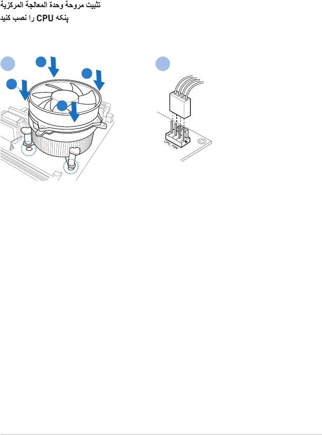
1.6.2 Installing the CPU heatsink and fan The Intel LGA775 processor requires a specially designed heatsink and fan assembly to ® ensure optimum thermal condition and performance. • When you buy a boxed Intel processor, the package includes the CPU fan and ®…
-
Page 21: Uninstalling The Cpu Heatsink And Fan
Connect the CPU fan cable to the connector on the motherboard labeled CPU_FAN. CPU_FAN P5G41T-M LX3 P5G41T-M LX3 CPU fan connector Do not forget to connect the CPU fan connector! Hardware monitoring errors can occur if you fail to plug this connector.
-
Page 22: System Memory
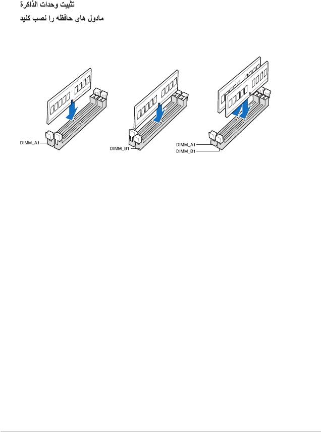
The motherboard comes with two Double Data Rate 3 (DDR3) Dual Inline Memory Modules (DIMM) sockets. The figure illustrates the location of the DDR3 DIMM sockets: Channel Sockets Channel A DIMM_A1 Channel B DIMM_B1 P5G41T-M LX3 P5G41T-M LX3 240-pin DDR3 DIMM sockets 1-12 Chapter 1: Product introduction…
-
Page 23: Memory Configurations
Under the default state, some memory modules for overclocking may operate at a lower frequency than the vendor-marked value. • For system stability, use a more efficient cooling system to support a full memory load (2 DIMMs) or overclocking conditions. P5G41T-M LX3 Motherboard Qualified Vendors Lists (QVL) DDR3-1066 MHz capability DIMM socket support…
-
Page 24: Ddr3-1333 Mhz Capability
• A*: Supports one module inserted into any slot as Single-channel memory configuration. • B*: Supports one pair of modules inserted into both the blue slots as one pair of Dual-channel memory configuration. Visit the ASUS website at www.asus.com for the latest QVL. 1-14 Chapter 1: Product introduction…
-
Page 25: Installing A Dimm
DIMM. Support the DIMM lightly with your fingers when pressing the retaining clips. The DIMM might get damaged when it flips out with extra force. DIMM notch Remove the DIMM from the socket. ASUS P5G41T-M LX3 1-15…
-
Page 26: Expansion Slots
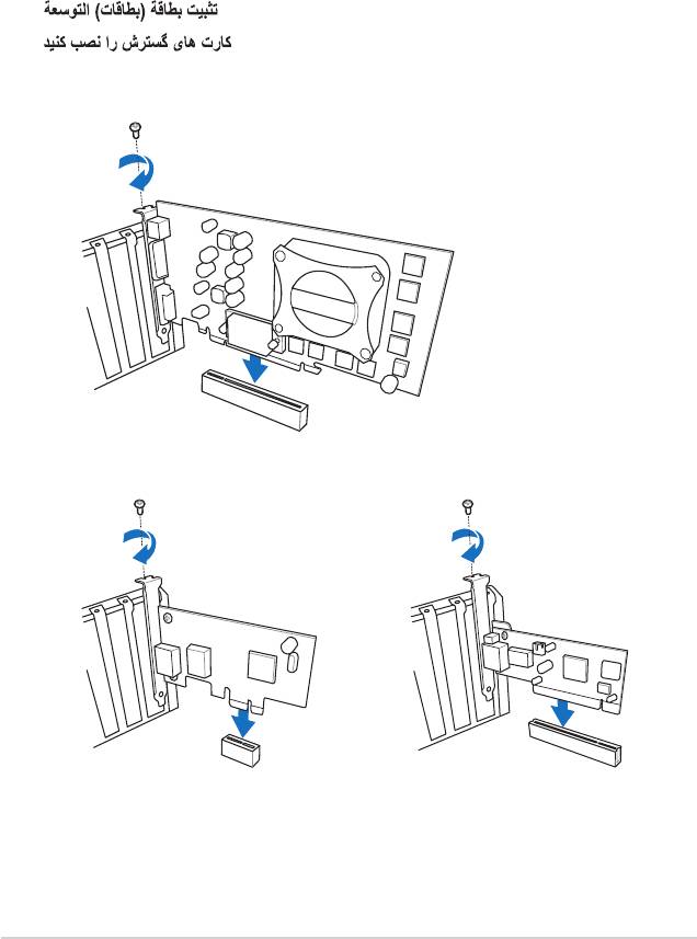
Expansion slots In the future, you may need to install expansion cards. The following sub-sections describe the slots and the expansion cards that they support. Unplug the power cord before adding or removing expansion cards. Failure to do so may cause you physical injury and damage motherboard components.
-
Page 27: Jumpers
Clear RTC P5G41T-M LX3 (Default) P5G41T-M LX3 Clear RTC RAM To erase the RTC RAM: 1. Turn OFF the computer and unplug the power cord. 2. Move the jumper cap from pins 1-2 (default) to pins 2-3. Keep the cap on pins 2-3 for about 5-10 seconds, then move the cap back to pins 1-2.
-
Page 28: Keyboard Power
P5G41T-M LX3 +5VSB (Default) P5G41T-M LX3 USB Device Wake Up • The USB device wake-up feature requires a power supply that can provide 500mA on the +5VSB lead for each USB port; otherwise, the system would not power up. • The total current consumed must NOT exceed the power supply capability (+5VSB) whether under normal condition or in sleep mode.
-
Page 29: Connectors
Mic In Mic In Bass/Center Bass/Center Lime (Front panel) – – – Side Speaker Out To configure an 8-channel audio output: Use the chassis with HD audio module in the front panel to support 8-channel audio output. ASUS P5G41T-M LX3 1-19…
-
Page 30: Internal Connectors
Legacy AC’97 pin definition compliant definition P5G41T-M LX3 Front panel audio connector • We recommend that you connect a high-definition front panel audio module to this connector to avail of the motherboard’s high-definition audio capability. • If you want to connect a high-definition front panel audio module to this connector, set the Front Panel Type item in the BIOS setup to [HD Audio].
-
Page 31: Atx Power Connectors
The system may become unstable or may not boot up if the power is inadequate. • If you are uncertain about the minimum power supply requirement for your system, refer to the Recommended Power Supply Wattage Calculator at http://support.asus. com/PowerSupplyCalculator/PSCalculator.aspx?SLanguage=en-us for details. ASUS P5G41T-M LX3…
-
Page 32
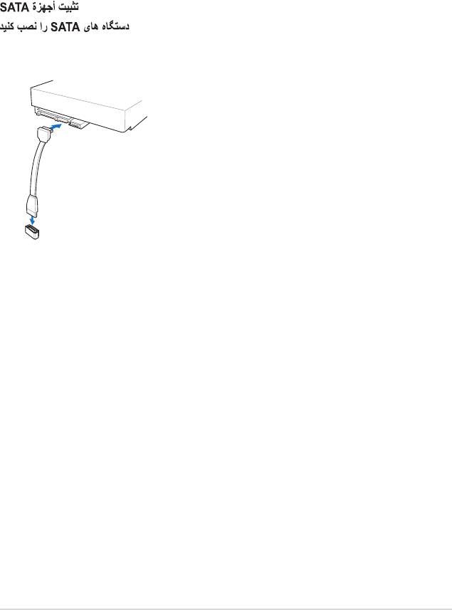
SATA4 SATA1 SATA2 SATA3 P5G41T-M LX3 P5G41T-M LX3 SATA connectors Install the Windows XP Service Pack 3 or later version before using Serial ATA. ® USB connectors (10-1 pin USB56, USB78) These connectors are for USB 2.0 ports. Connect the USB module cable to any of these connectors, then install the module to a slot opening at the back of the system chassis. -
Page 33
P5G41T-M LX3 Rotation P5G41T-M LX3 fan connectors Only the 4-pin CPU fan supports the ASUS Q-FAN feature. Digital audio connector (4-1 pin SPDIF_OUT) This connector is for an additional Sony/Philips Digital Interface (S/PDIF) port. Connect the S/PDIF Out module cable to this connector, then install the module to a slot opening at the back of the system chassis. -
Page 34: System Panel Connector
PIN 1 P5G41T-M LX3 HD_LED RESET P5G41T-M LX3 System panel connector • System power LED (2-pin PLED) This 2-pin connector is for the system power LED. Connect the chassis power LED cable to this connector. The system power LED lights up when you turn on the system power, and blinks when the system is in sleep mode.
-
Page 35: Software Support
The contents of the Support DVD are subject to change at any time without notice. Visit the ASUS website at www.asus.com for updates. To run the Support DVD Place the Support DVD to the optical drive.
-
Page 36
1-26 Chapter 1: Product introduction… -
Page 37: Managing And Updating Your Bios
BIOS in the future. Copy the original motherboard BIOS using the ASUS Update utility. 2.1.1 ASUS Update utility The ASUS Update is a utility that allows you to manage, save, and update the motherboard BIOS in Windows environment. ®…
-
Page 38: Asus Ez Flash 2
Follow the onscreen instructions to complete the updating process. 2.1.2 ASUS EZ Flash 2 The ASUS EZ Flash 2 feature allows you to update the BIOS without using an OS-based utility. Before you start using this utility, download the latest BIOS file from the ASUS website at www.asus.com.
-
Page 39: Asus Crashfree Bios
2.1.3 ASUS CrashFree BIOS The ASUS CrashFree BIOS is an auto recovery tool that allows you to restore the BIOS file when it fails or gets corrupted during the updating process. You can restore a corrupted BIOS file using the motherboard support DVD or a removable device that contains the updated BIOS file.
-
Page 40: Bios Setup Program
• The BIOS setup screens shown in this section are for reference purposes only, and may not exactly match what you see on your screen. • Visit the ASUS website at www.asus.com to download the latest BIOS file for this motherboard.
-
Page 41: Bios Menu Screen
For configuring options for special functions. Exit For selecting the exit options and loading default settings. To select an item on the menu bar, press the right or left arrow key on the keyboard until the desired item is highlighted. ASUS P5G41T-M LX3…
-
Page 42: Navigation Keys
2.2.3 Navigation keys At the bottom right corner of a menu screen are the navigation keys for that particular menu. Use the navigation keys to select items in the menu and change the settings. Some of the navigation keys differ from one screen to another. 2.2.4 Menu items The highlighted item on the menu bar displays the specific items for that menu.
-
Page 43: Main Menu
LBA/Large Mode [Auto] Enables or disables the LBA mode. Setting to [Auto] enables the LBA mode if the device supports this mode, and if the device was not previously formatted with LBA mode disabled. Configuration options: [Disabled] [Auto] ASUS P5G41T-M LX3…
-
Page 44: Storage Configuration
Block (Multi-sector Transfer) M [Auto] Enables or disables data multi-sectors transfers. When set to [Auto], the data transfer from and to the device occurs multiple sectors at a time if the device supports multi-sector transfer feature. When set to [Disabled], the data transfer from and to the device occurs one sector at a time.
-
Page 45: System Information
Select either one of the preset overclocking configuration options: Manual — allows you to individually set overclocking parameters. Auto — loads the optimal settings for the system. Overclock Profile — loads overclocking profiles with optimal parameters for stability when overclocking. ASUS P5G41T-M LX3…
-
Page 46
The following two items appear only when you set the AI Overclocking item to [MANUAL]. CPU Frequency [xxx] Displays the frequency sent by the clock generator to the system bus and PCI bus. The value of this item is auto-detected by the BIOS. Use the <+> and <-> keys to adjust the CPU frequency. -
Page 47: Cpu Configuration
Virtualization Technology. Virtualization enhanced by Intel ® ® Virtualization Technology allows a platform to run multiple operating systems and applications in independent partitions. With virtualization, one computer system can function as multiple virtual systems. Configuration options: [Enabled] [Disabled] ASUS P5G41T-M LX3 2-11…
-
Page 48: Chipset
CPU TM Function [Enabled] Enables or disables Intel CPU Thermal Monitor (TM) function, a CPU overheating protection ® function. When enabled, the CPU core frequency and voltage are reduced when the CPU overheats. Configuration options: [Disabled] [Enabled] Execute-Disable Bit Capability [Enabled] Allows you to enable or disable the No-Execution Page Protection Technology.
-
Page 49: Onboard Devices Configuration
Allows you to enable or disable the boot ROM in the onboard LAN controller. This item appears only when the Onboard LAN item is set to Enabled. Configuration options: [Disabled] [Enabled] Serial Port1 Address [3F8/IRQ4] Allows you to select the Serial Port1 base address. Configuration options: [Disabled] [3F8/IRQ4] [2F8/IRQ3] [3E8/IRQ4] [2E8/IRQ3] ASUS P5G41T-M LX3 2-13…
-
Page 50: Usb Configuration
2.4.5 USB Configuration The items in this menu allows you to change the USB-related features. Select an item then press <Enter> to display the configuration options. The Module Version and USB Devices Enabled items show the auto-detected values. If no USB device is detected, the item shows None.
-
Page 51: Pci Pnp
Allows you to enable or disable the Advanced Configuration and Power Interface (ACPI) support in the Application-Specific Integrated Circuit (ASIC). When set to Enabled, the ACPI APIC table pointer is included in the RSDT pointer list. Configuration options: [Disabled] [Enabled] ASUS P5G41T-M LX3 2-15…
-
Page 52: Apm Configuration
2.5.4 APM Configuration Restore on AC Power Loss [Power Off] When set to [Power Off], the system goes into off state after an AC power loss. When set to [Power On], the system goes on after an AC power loss. When set to [Last State], the system goes into either off or on state, whatever the system state was before the AC power loss.
-
Page 53: Boot Menu
Configuration options: [Removable Dev.] [Hard Drive] [ATAPI CD-ROM] [Disabled] • To select the boot device during system startup, press <F8> when ASUS Logo appears. • To access Windows OS in Safe Mode, do any of the following: ®…
-
Page 54: Security
Full Screen Logo [Enabled] This allows you to enable or disable the full screen logo display feature. Configuration options: [Disabled] [Enabled] Set this item to [Enabled] to use the ASUS MyLogo2 feature. ™ AddOn ROM Display Mode [Force BIOS] Sets the display mode for option ROM. Configuration options: [Force BIOS] [Keep Current] Bootup Num-Lock [On] Allows you to select the power-on state for the NumLock.
-
Page 55: Change User Password
Password Check [Setup] When set to [Setup], BIOS checks for user password when accessing the Setup utility. When set to [Always], BIOS checks for user password both when accessing Setup and booting the system. Configuration options: [Setup] [Always] ASUS P5G41T-M LX3 2-19…
-
Page 56: Tools Menu
3.CD-DISC (read only) ASUS EZ Flash 2 Allows you to run ASUS EZ Flash 2. When you press <Enter>, a confirmation message appears. Use the left/right arrow key to select between [Yes] or [No], then press <Enter> to confirm your choice. See section 2.1.2 ASUS EZ Flash 2 for details.
-
Page 57: Exit Menu
When you select this option or if you press <F5>, a confirmation window appears. Select OK to load default values. Select Exit & Save Changes or make other changes before saving the values to the non-volatile RAM. ASUS P5G41T-M LX3 2-21…
-
Page 58
2-22 Chapter 2: BIOS information… -
Page 59: Asus Contact Information
+1-510-739-3777 +1-510-608-4555 Web site usa.asus.com Technical Support Telephone +1-812-282-2787 Support fax +1-812-284-0883 Online support support.asus.com ASUS COMPUTER GmbH (Germany and Austria) Address Harkort Str. 21-23, D-40880 Ratingen, Germany +49-2102-959911 Web site www.asus.de Online contact www.asus.de/sales Technical Support Telephone (Component) +49-1805-010923*…
Посмотреть инструкция для Asus P5G41T-M LX3 бесплатно. Руководство относится к категории материнские платы, 7 человек(а) дали ему среднюю оценку 8.8. Руководство доступно на следующих языках: английский. У вас есть вопрос о Asus P5G41T-M LX3 или вам нужна помощь? Задайте свой вопрос здесь
Материнская плата Asus P5G41T-M LX3 является устройством, которое поддерживает процессоры Intel с LGA 775 разъемом и возможностью работы на системной шине 800, 1066 и 1333 МГц. Она имеет два слота под оперативную память, которые поддерживают модули с тактовой частотой 800, 1066 и 1333 МГц, общим объёмом до 8 ГБ и без проверки чётности (Non-ECC). Материнская плата поддерживает Intel Core 2 Duo серии E4000, E6000, E7000, E8000, Intel Core 2 Quad серии Q6000, Q8000, Q9000, Intel Pentium серии E2000, E5000, E6000 и Intel Celeron серии 400, E1000.
Asus P5G41T-M LX3 имеет 4 разъёма USB 2.0 для подключения устройств, а также возможность работы одного процессора SMP. Для охлаждения материнской платы используется высококачественный радиатор. Дизайн материнской платы поддерживает низкий уровень энергопотребления благодаря технологии ASUS EPU.
Материнская плата имеет малый форм-фактор (MicroATX) и компактна, поэтому она охватывает широкий спектр возможностей, включая использование в домашнем ПК или офисном компьютере. Общие размеры материнской платы составляют 24,4 см × 19,8 см. Asus P5G41T-M LX3 — надежное и долговечное устройство, способное обеспечить высокую производительность вашего компьютера.

Главная
| Asus | |
| P5G41T-M LX3 | P5G41T-M LX3 | |
| материнская плата | |
| 5711045381409, 0610839178476 | |
| английский | |
| Руководство пользователя (PDF) |
Память
| без функции коррекции ошибок | Да |
| Максимальная внутренняя память | 8 GB |
| Количество слотов памяти | 2 |
| Поддерживаемые частоты памяти | 800,1066,1333 MHz |
| Каналы памяти | Dual-channel |
Процессор
| Производитель процессора | Intel |
| Сокет процессора | LGA 775 (Socket T) |
| Совместимые серии процессоров | Intel Celeron, Intel Pentium Dual-Core |
| Поддерживаемые системные шины процессора | 800,1066,1333 MHz |
| Максимальное число процессоров для SMP | 1 |
| Intel Core 2 Duo серия | E4000, E6000, E7000, E8000 |
| Intel Core 2 Quad серия | Q6000, Q8000, Q9000 |
| Intel Pentium серия | E2000, E5000, E6000 |
| Intel Celeron серия | 400, E1000 |
Внутренние порты
| Разъемы USB 2.0 | 4 |
| Разъем выхода S/PDIF | Да |
| Разъем вентилятора центрального процессора | Да |
| Разъем питания ATX (24-конт.) | Да |
| Количество разъемов питания EATX | 1 |
| Разъем Chassis intrusion | Да |
| Количество параллельных разъемов ATA (PATA) | — |
| Аудиоразъем передней панели | Да |
| Количество разъемов SATA II | 4 |
Порты на задней панели
| Количество последовательных портов | 1 |
| Количество портов PS/2 | 2 |
| Количество портов USB 2.0 | 4 |
| Порты FireWire | 0 |
| Количество портов Ethernet LAN ( RJ-45) | 1 |
| Линейные выходы наушников | 1 |
| Линейный вход микрофона | Да |
| Количество портов VGA (D-Sub) | 1 |
| Количество портов eSATA | 0 |
| Количество портов DVI-D | 0 |
| Количество HDMI портов | 0 |
| Количество портов USB 3.2 Gen 1 (3.1 Gen 1) Type-A | 0 |
Свойства
| Формат материнской платы | Микро ATX |
| Чипсет материнской платы | Intel® G41 |
| Совместимые операционные системы | Windows OS |
| Комплектующие для | ПК |
| Аудио чип | Realtek ALC887 |
| Выходные звуковые каналы | 7.1 канала |
| Тип источника питания | ATX |
Графический адаптер
| Поддержка технологии параллельной обработки | Не поддерживается |
| Объём памяти графического адаптера | 256 MB |
| Видеокарта | GMA X4500 |
| Встроенный графический адаптер | Да |
| Семейство графического адаптера | Intel |
Слоты расширения
| PCI Express x16 слоты | 1 |
| PCI Express x1 слоты | 2 |
| PCI-X слоты | 1 |
Вес и размеры
| Ширина | 244 mm |
| Глубина | 188 mm |
Прочие свойства
| Краткое руководство по установке | Да |
Сеть
| Характеристики сети | Гигабитный Ethernet |
| Тип Ethernet интерфейса | Гигабитный Ethernet |
BIOS
| Тип BIOS | AMI |
| Размер памяти BIOS | 64 Mbit |
| Версия ACPI | 2.0 |
показать больше
Не можете найти ответ на свой вопрос в руководстве? Вы можете найти ответ на свой вопрос ниже, в разделе часто задаваемых вопросов о Asus P5G41T-M LX3.
Какая ширина Asus P5G41T-M LX3?
Asus P5G41T-M LX3 имеет ширину 244 mm.
Какая толщина Asus P5G41T-M LX3?
Asus P5G41T-M LX3 имеет толщину 188 mm.
Инструкция Asus P5G41T-M LX3 доступно в русский?
К сожалению, у нас нет руководства для Asus P5G41T-M LX3, доступного в русский. Это руководство доступно в английский.
Не нашли свой вопрос? Задайте свой вопрос здесь
Техподдержка
P5G41T-M LX3
Найти другую модель
Регистрация устройства поможет вам управлять его гарантией, получать техническую поддержку и отслеживать статус ремонта.
Регистрация продукта
Руководства пользователя
Версия C6280
3.74 MB
P5G41T-M LX3 User’s Manual (Chinese Simplified)
СКАЧАТЬ
Версия E6280
3.36 MB
P4G41T-M LX3 user’s manual(English)
СКАЧАТЬ
Версия f6280
2.13 MB
P5G41T-M LX3 User’s Manual (French)
СКАЧАТЬ
Посмотреть инструкция для Asus P5G41T-M LX3 бесплатно. Руководство относится к категории Материнские платы, 7 человек(а) дали ему среднюю оценку 8.8. Руководство доступно на следующих языках: английский. У вас есть вопрос о Asus P5G41T-M LX3 или вам нужна помощь? Задайте свой вопрос здесь
Не можете найти ответ на свой вопрос в руководстве? Вы можете найти ответ на свой вопрос ниже, в разделе часто задаваемых вопросов о Asus P5G41T-M LX3.
Какая ширина Asus P5G41T-M LX3?
Какая толщина Asus P5G41T-M LX3?
Инструкция Asus P5G41T-M LX3 доступно в русский?
Не нашли свой вопрос? Задайте свой вопрос здесь
-
Contents
-
Table of Contents
-
Bookmarks
Quick Links
Related Manuals for Asus P5G41T-M LX3
Summary of Contents for Asus P5G41T-M LX3
-
Page 1
P5G41T-M LX3… -
Page 2
Product warranty or service will not be extended if: (1) the product is repaired, modified or altered, unless such repair, modification of alteration is authorized in writing by ASUS; or (2) the serial number of the product is defaced or missing. -
Page 3: Table Of Contents
Contents Notices ………………….vi Safety information ………………vii About this guide ………………vii P5G41T-M LX3 specifications summary ……….. ix Chapter 1: Product introduction Welcome! ………………1-1 Package contents …………….. 1-1 Special features …………….1-1 1.3.1 Product highlights …………1-1 1.3.2 Innovative ASUS features ……….
-
Page 4
Chapter 2: BIOS information Managing and updating your BIOS ……….2-1 2.1.1 ASUS Update utility …………2-1 2.1.2 ASUS EZ Flash 2 …………2-2 2.1.3 ASUS CrashFree BIOS ……….. 2-3 BIOS setup program …………..2-4 2.2.1 BIOS menu screen …………2-5 2.2.2… -
Page 5
APM Configuration …………2-16 2.5.6 Hardware Monitor …………2-16 Boot menu ……………… 2-17 2.6.1 Boot Device Priority …………2-17 2.6.2 Boot Settings Configuration ………. 2-17 2.6.3 Security …………….. 2-18 Tools menu …………….. 2-20 ASUS EZ Flash 2 …………….. 2-20 Exit menu ………………2-21… -
Page 6: Notices
Complying with the REACH (Registration, Evaluation, Authorisation, and Restriction of Chemicals) regulatory framework, we published the chemical substances in our products at ASUS REACH website at http://csr.asus.com/english/REACH.htm. DO NOT throw the motherboard in municipal waste. This product has been designed to enable proper reuse of parts and recycling.
-
Page 7: Safety Information
Safety information Electrical safety • To prevent electric shock hazard, disconnect the power cable from the electric outlet before relocating the system. • When adding or removing devices to or from the system, ensure that the power cables for the devices are unplugged before the signal cables are connected. If possible, disconnect all power cables from the existing system before you add a device.
-
Page 8: Conventions Used In This Guide
Refer to the following sources for additional information and for product and software updates. ASUS websites The ASUS website provides updated information on ASUS hardware and software products. Refer to the ASUS contact information. Optional documentation Your product package may include optional documentation, such as warranty flyers, that may have been added by your dealer.
-
Page 9: P5G41T-M Lx3 Specifications Summary
— 2 x 240-pin DIMM sockets support unbuffered non-ECC 1333(O.C.)/1066 MHz DDR3 memory modules — Supports up to 8GB system memory * Refer to www.asus.com for the latest Memory QVL (Qualified Vendors Lists). ** When you install a total memory of 4GB or more, Windows®…
-
Page 10
P5G41T-M LX3 specifications summary ASUS unique ASUS CrashFree BIOS 3 features ASUS Q-Fan ASUS EZ Flash 2 ASUS MyLogo 2 ASUS Turbo Key ASUS EPU-L Back panel I/O ports 1 x PS/2 keyboard port 1 x PS/2 mouse port 1 x COM port… -
Page 11: Chapter 1: Product Introduction
® The motherboard delivers a host of new features and latest technologies, making it another standout in the long line of ASUS quality motherboards! Before you start installing the motherboard, and hardware devices on it, check the items in your package with the list below.
-
Page 12: Innovative Asus Features
Turbo Key ASUS Turbo Key allows you to turn the PC power button into an overclocking button. After you easy setup, Turbo Key boosts performances without interrupting ongoing work or games, simply through pressing the button.
-
Page 13
BIOS file using the bundled support DVD or USB flash disk that contains the latest BIOS file. ASUS EZ Flash 2 ASUS EZ Flash 2 is a utility that allows you to update the BIOS without using an OS-based utility. C.P.R. (CPU Parameter Recall) The BIOS C.P.R. -
Page 14: Before You Proceed
The illustration below shows the location of the onboard LED. SB_PWR P5G41T-M LX3 Standby Power Powered Off P5G41T-M LX3 Onboard LED Chapter 1: Product introduction…
-
Page 15: Motherboard Overview
Place six screws into the holes indicated by circles to secure the motherboard to the chassis. Do not overtighten the screws! Doing so can damage the motherboard. Place this side towards the rear of the chassis P5G41T-M LX3 ASUS P5G41T-M LX3…
-
Page 16: Motherboard Layout
USB34 8103EL LAN1_USB12 Intel ® CHA_FAN 9LRS954 AUDIO Lithium Cell PCIEX1_1 CMOS Power ATHEROS 8151 PCIEX16 Super Intel ® PCIEX1_2 P5G41T-M LX3 ICH7 PCI1 ALC887 SB_PWR USB56 USB78 BIOS SPEAKER F_PANEL SATA1 SATA2 CLRTC SPDIF_OUT AAFP USBPW5-8 3 10 1.5.4…
-
Page 17: Central Processing Unit (Cpu)
Contact your retailer immediately if the PnP cap is missing, or if you see any damage to the PnP cap/socket contacts/motherboard components. ASUS will shoulder the cost of repair only if the damage is shipment/transit-related. • Keep the cap after installing the motherboard. ASUS will process Return Merchandise Authorization (RMA) requests only if the motherboard comes with the cap on the LGA775 socket.
-
Page 18
Press the load lever with your thumb Retention tab (A), then move it to the left (B) until it is released from the retention tab. To prevent damage to the socket pins, do not remove the PnP cap unless you are installing a CPU. Load lever Lift the load lever in the direction of the PnP cap… -
Page 19
To prevent contaminating the paste, DO NOT spread the paste with your finger directly. Close the load plate (A), then push the load lever (B) until it snaps into the retention tab. ASUS P5G41T-M LX3… -
Page 20: Installing The Cpu Heatsink And Fan
1.6.2 Installing the CPU heatsink and fan The Intel LGA775 processor requires a specially designed heatsink and fan assembly to ® ensure optimum thermal condition and performance. • When you buy a boxed Intel processor, the package includes the CPU fan and ®…
-
Page 21: Uninstalling The Cpu Heatsink And Fan
Connect the CPU fan cable to the connector on the motherboard labeled CPU_FAN. CPU_FAN P5G41T-M LX3 P5G41T-M LX3 CPU fan connector Do not forget to connect the CPU fan connector! Hardware monitoring errors can occur if you fail to plug this connector.
-
Page 22: System Memory
The motherboard comes with two Double Data Rate 3 (DDR3) Dual Inline Memory Modules (DIMM) sockets. The figure illustrates the location of the DDR3 DIMM sockets: Channel Sockets Channel A DIMM_A1 Channel B DIMM_B1 P5G41T-M LX3 P5G41T-M LX3 240-pin DDR3 DIMM sockets 1-12 Chapter 1: Product introduction…
-
Page 23: Memory Configurations
Under the default state, some memory modules for overclocking may operate at a lower frequency than the vendor-marked value. • For system stability, use a more efficient cooling system to support a full memory load (2 DIMMs) or overclocking conditions. P5G41T-M LX3 Motherboard Qualified Vendors Lists (QVL) DDR3-1066 MHz capability DIMM socket support…
-
Page 24: Ddr3-1333 Mhz Capability
• A*: Supports one module inserted into any slot as Single-channel memory configuration. • B*: Supports one pair of modules inserted into both the blue slots as one pair of Dual-channel memory configuration. Visit the ASUS website at www.asus.com for the latest QVL. 1-14 Chapter 1: Product introduction…
-
Page 25: Installing A Dimm
DIMM. Support the DIMM lightly with your fingers when pressing the retaining clips. The DIMM might get damaged when it flips out with extra force. DIMM notch Remove the DIMM from the socket. ASUS P5G41T-M LX3 1-15…
-
Page 26: Expansion Slots
Expansion slots In the future, you may need to install expansion cards. The following sub-sections describe the slots and the expansion cards that they support. Unplug the power cord before adding or removing expansion cards. Failure to do so may cause you physical injury and damage motherboard components.
-
Page 27: Jumpers
Clear RTC P5G41T-M LX3 (Default) P5G41T-M LX3 Clear RTC RAM To erase the RTC RAM: 1. Turn OFF the computer and unplug the power cord. 2. Move the jumper cap from pins 1-2 (default) to pins 2-3. Keep the cap on pins 2-3 for about 5-10 seconds, then move the cap back to pins 1-2.
-
Page 28: Keyboard Power
P5G41T-M LX3 +5VSB (Default) P5G41T-M LX3 USB Device Wake Up • The USB device wake-up feature requires a power supply that can provide 500mA on the +5VSB lead for each USB port; otherwise, the system would not power up. • The total current consumed must NOT exceed the power supply capability (+5VSB) whether under normal condition or in sleep mode.
-
Page 29: Connectors
Mic In Mic In Bass/Center Bass/Center Lime (Front panel) – – – Side Speaker Out To configure an 8-channel audio output: Use the chassis with HD audio module in the front panel to support 8-channel audio output. ASUS P5G41T-M LX3 1-19…
-
Page 30: Internal Connectors
Legacy AC’97 pin definition compliant definition P5G41T-M LX3 Front panel audio connector • We recommend that you connect a high-definition front panel audio module to this connector to avail of the motherboard’s high-definition audio capability. • If you want to connect a high-definition front panel audio module to this connector, set the Front Panel Type item in the BIOS setup to [HD Audio].
-
Page 31: Atx Power Connectors
The system may become unstable or may not boot up if the power is inadequate. • If you are uncertain about the minimum power supply requirement for your system, refer to the Recommended Power Supply Wattage Calculator at http://support.asus. com/PowerSupplyCalculator/PSCalculator.aspx?SLanguage=en-us for details. ASUS P5G41T-M LX3…
-
Page 32
SATA4 SATA1 SATA2 SATA3 P5G41T-M LX3 P5G41T-M LX3 SATA connectors Install the Windows XP Service Pack 3 or later version before using Serial ATA. ® USB connectors (10-1 pin USB56, USB78) These connectors are for USB 2.0 ports. Connect the USB module cable to any of these connectors, then install the module to a slot opening at the back of the system chassis. -
Page 33
P5G41T-M LX3 Rotation P5G41T-M LX3 fan connectors Only the 4-pin CPU fan supports the ASUS Q-FAN feature. Digital audio connector (4-1 pin SPDIF_OUT) This connector is for an additional Sony/Philips Digital Interface (S/PDIF) port. Connect the S/PDIF Out module cable to this connector, then install the module to a slot opening at the back of the system chassis. -
Page 34: System Panel Connector
PIN 1 P5G41T-M LX3 HD_LED RESET P5G41T-M LX3 System panel connector • System power LED (2-pin PLED) This 2-pin connector is for the system power LED. Connect the chassis power LED cable to this connector. The system power LED lights up when you turn on the system power, and blinks when the system is in sleep mode.
-
Page 35: Software Support
The contents of the Support DVD are subject to change at any time without notice. Visit the ASUS website at www.asus.com for updates. To run the Support DVD Place the Support DVD to the optical drive.
-
Page 36
1-26 Chapter 1: Product introduction… -
Page 37: Managing And Updating Your Bios
BIOS in the future. Copy the original motherboard BIOS using the ASUS Update utility. 2.1.1 ASUS Update utility The ASUS Update is a utility that allows you to manage, save, and update the motherboard BIOS in Windows environment. ®…
-
Page 38: Asus Ez Flash 2
Follow the onscreen instructions to complete the updating process. 2.1.2 ASUS EZ Flash 2 The ASUS EZ Flash 2 feature allows you to update the BIOS without using an OS-based utility. Before you start using this utility, download the latest BIOS file from the ASUS website at www.asus.com.
-
Page 39: Asus Crashfree Bios
2.1.3 ASUS CrashFree BIOS The ASUS CrashFree BIOS is an auto recovery tool that allows you to restore the BIOS file when it fails or gets corrupted during the updating process. You can restore a corrupted BIOS file using the motherboard support DVD or a removable device that contains the updated BIOS file.
-
Page 40: Bios Setup Program
• The BIOS setup screens shown in this section are for reference purposes only, and may not exactly match what you see on your screen. • Visit the ASUS website at www.asus.com to download the latest BIOS file for this motherboard.
-
Page 41: Bios Menu Screen
For configuring options for special functions. Exit For selecting the exit options and loading default settings. To select an item on the menu bar, press the right or left arrow key on the keyboard until the desired item is highlighted. ASUS P5G41T-M LX3…
-
Page 42: Navigation Keys
2.2.3 Navigation keys At the bottom right corner of a menu screen are the navigation keys for that particular menu. Use the navigation keys to select items in the menu and change the settings. Some of the navigation keys differ from one screen to another. 2.2.4 Menu items The highlighted item on the menu bar displays the specific items for that menu.
-
Page 43: Main Menu
LBA/Large Mode [Auto] Enables or disables the LBA mode. Setting to [Auto] enables the LBA mode if the device supports this mode, and if the device was not previously formatted with LBA mode disabled. Configuration options: [Disabled] [Auto] ASUS P5G41T-M LX3…
-
Page 44: Storage Configuration
Block (Multi-sector Transfer) M [Auto] Enables or disables data multi-sectors transfers. When set to [Auto], the data transfer from and to the device occurs multiple sectors at a time if the device supports multi-sector transfer feature. When set to [Disabled], the data transfer from and to the device occurs one sector at a time.
-
Page 45: System Information
Select either one of the preset overclocking configuration options: Manual — allows you to individually set overclocking parameters. Auto — loads the optimal settings for the system. Overclock Profile — loads overclocking profiles with optimal parameters for stability when overclocking. ASUS P5G41T-M LX3…
-
Page 46
The following two items appear only when you set the AI Overclocking item to [MANUAL]. CPU Frequency [xxx] Displays the frequency sent by the clock generator to the system bus and PCI bus. The value of this item is auto-detected by the BIOS. Use the <+> and <-> keys to adjust the CPU frequency. -
Page 47: Cpu Configuration
Virtualization Technology. Virtualization enhanced by Intel ® ® Virtualization Technology allows a platform to run multiple operating systems and applications in independent partitions. With virtualization, one computer system can function as multiple virtual systems. Configuration options: [Enabled] [Disabled] ASUS P5G41T-M LX3 2-11…
-
Page 48: Chipset
CPU TM Function [Enabled] Enables or disables Intel CPU Thermal Monitor (TM) function, a CPU overheating protection ® function. When enabled, the CPU core frequency and voltage are reduced when the CPU overheats. Configuration options: [Disabled] [Enabled] Execute-Disable Bit Capability [Enabled] Allows you to enable or disable the No-Execution Page Protection Technology.
-
Page 49: Onboard Devices Configuration
Allows you to enable or disable the boot ROM in the onboard LAN controller. This item appears only when the Onboard LAN item is set to Enabled. Configuration options: [Disabled] [Enabled] Serial Port1 Address [3F8/IRQ4] Allows you to select the Serial Port1 base address. Configuration options: [Disabled] [3F8/IRQ4] [2F8/IRQ3] [3E8/IRQ4] [2E8/IRQ3] ASUS P5G41T-M LX3 2-13…
-
Page 50: Usb Configuration
2.4.5 USB Configuration The items in this menu allows you to change the USB-related features. Select an item then press <Enter> to display the configuration options. The Module Version and USB Devices Enabled items show the auto-detected values. If no USB device is detected, the item shows None.
-
Page 51: Pci Pnp
Allows you to enable or disable the Advanced Configuration and Power Interface (ACPI) support in the Application-Specific Integrated Circuit (ASIC). When set to Enabled, the ACPI APIC table pointer is included in the RSDT pointer list. Configuration options: [Disabled] [Enabled] ASUS P5G41T-M LX3 2-15…
-
Page 52: Apm Configuration
2.5.4 APM Configuration Restore on AC Power Loss [Power Off] When set to [Power Off], the system goes into off state after an AC power loss. When set to [Power On], the system goes on after an AC power loss. When set to [Last State], the system goes into either off or on state, whatever the system state was before the AC power loss.
-
Page 53: Boot Menu
Configuration options: [Removable Dev.] [Hard Drive] [ATAPI CD-ROM] [Disabled] • To select the boot device during system startup, press <F8> when ASUS Logo appears. • To access Windows OS in Safe Mode, do any of the following: ®…
-
Page 54: Security
Full Screen Logo [Enabled] This allows you to enable or disable the full screen logo display feature. Configuration options: [Disabled] [Enabled] Set this item to [Enabled] to use the ASUS MyLogo2 feature. ™ AddOn ROM Display Mode [Force BIOS] Sets the display mode for option ROM. Configuration options: [Force BIOS] [Keep Current] Bootup Num-Lock [On] Allows you to select the power-on state for the NumLock.
-
Page 55: Change User Password
Password Check [Setup] When set to [Setup], BIOS checks for user password when accessing the Setup utility. When set to [Always], BIOS checks for user password both when accessing Setup and booting the system. Configuration options: [Setup] [Always] ASUS P5G41T-M LX3 2-19…
-
Page 56: Tools Menu
3.CD-DISC (read only) ASUS EZ Flash 2 Allows you to run ASUS EZ Flash 2. When you press <Enter>, a confirmation message appears. Use the left/right arrow key to select between [Yes] or [No], then press <Enter> to confirm your choice. See section 2.1.2 ASUS EZ Flash 2 for details.
-
Page 57: Exit Menu
When you select this option or if you press <F5>, a confirmation window appears. Select OK to load default values. Select Exit & Save Changes or make other changes before saving the values to the non-volatile RAM. ASUS P5G41T-M LX3 2-21…
-
Page 58
2-22 Chapter 2: BIOS information… -
Page 59: Asus Contact Information
+1-510-739-3777 +1-510-608-4555 Web site usa.asus.com Technical Support Telephone +1-812-282-2787 Support fax +1-812-284-0883 Online support support.asus.com ASUS COMPUTER GmbH (Germany and Austria) Address Harkort Str. 21-23, D-40880 Ratingen, Germany +49-2102-959911 Web site www.asus.de Online contact www.asus.de/sales Technical Support Telephone (Component) +49-1805-010923*…
-
Драйверы
22
-
Инструкции по эксплуатации
7
Языки:

ASUS P5G41T-M LX3 инструкция по эксплуатации
(60 страниц)
- Языки:Английский
-
Тип:
PDF -
Размер:
3.45 MB -
Описание:
P4G41T-M LX3 user’s manual(English)

ASUS P5G41T-M LX3 инструкция по эксплуатации
(58 страниц)
- Языки:Английский
-
Тип:
PDF -
Размер:
2.64 MB -
Описание:
P5G41T-M user’s manual (English)
Просмотр

ASUS P5G41T-M LX3 инструкция по эксплуатации
(60 страниц)
- Языки:Немецкий
-
Тип:
PDF -
Размер:
3.74 MB -
Описание:
P5G41T-M user’s manual (German)
Просмотр

ASUS P5G41T-M LX3 инструкция по эксплуатации
(58 страниц)
- Языки:Японский
-
Тип:
PDF -
Размер:
2.84 MB -
Описание:
P5G41T-M user’s manual (Japanese)
Просмотр

ASUS P5G41T-M LX3 инструкция по эксплуатации
(59 страниц)
- Языки:Французский
-
Тип:
PDF -
Размер:
2.61 MB -
Описание:
P5G41T-M user’s manual (French)
Просмотр

ASUS P5G41T-M LX3 инструкция по эксплуатации
(58 страниц)
- Языки:Китайский
-
Тип:
PDF -
Размер:
2.96 MB -
Описание:
P5G41T-M user’s manual (Traditional Chinese)
Просмотр

ASUS P5G41T-M LX3 инструкция по эксплуатации
(27 страниц)
-
Тип:
PDF -
Размер:
3.39 MB -
Описание:
P5G41T-M Asian Quick Start Guide for Multiple Languages
Просмотр
На NoDevice можно скачать инструкцию по эксплуатации для ASUS P5G41T-M LX3. Руководство пользователя необходимо для ознакомления с правилами установки и эксплуатации ASUS P5G41T-M LX3. Инструкции по использованию помогут правильно настроить ASUS P5G41T-M LX3, исправить ошибки и выявить неполадки.
Инструкция и руководство для
Asus P5G41-M LX на русском на испанском на французском на итальянском на чешском на немецком на польском


41 страница подробных инструкций и пользовательских руководств по эксплуатации
 12:31
12:31
Сборка бюджетного игрового компьютера
 06:52
06:52
Asus p5g41t-m lx2/gb + xeon e5450 — быстрый курс по установке ксеона
 13:35
13:35
ASUS P5G41-M LX XEON X5472 1600FSB+BECHMARK TEST+GTA V GAME TEST
 03:49
03:49
ОБЗОР МАТЕРИНСКОЙ ПЛАТЫ Asus p5g41t m lx2 v2
 08:22
08:22
Материнская плата c AliExpress LGA 775 ddr3 ( Asus p5p41t le )
 12:44
12:44
Разгон Xeon E5450 на Asus P5G41T-MLX
 17:56
17:56
XEON E5462 CPU 1600FSB-ASUS P5G41-M LX GAME TEST-BENCHMARK TEST
 02:53
02:53
Разгон Xeon e5450(x5450) на g41 чипсете
Français Deutsh Italiano Español Русский Português Polski Če…
P5g41-m lx, Motherboard, Quick start guide
- Изображение
- Текст
Français
Deutsh
Italiano
Español
Русский
Português
Polski
Česky
Magyar
Български
Română
Srpski
Türkçe
Quick Start Guide
First Edition
February 2009
Copyright © 2009 ASUSTeK COMPUTER INC.
All Rights Reserved
U4972
P5G41-M LX
Motherboard

Installer le cpu, Layout de la carte mère, Français
Asus p5g41-m lx, F_panel, P5g41-m lx, Usbpw5-8, Usbpw1-4, Kbpwr
- Изображение
- Текст
2
Français
ASUS P5G41-M LX
2.
Installer le CPU
Pour installer le CPU :
1. Pressez le levier avec votre pouce (A) et déplacez-le vers la gauche (B)
jusqu’à ce qu’il soit libéré de son onglet de rétention.
1.
Layout de la carte mère
A
B
Languette de
retenue
Levier
Ce côté doit être face à vous.
Capuchon PnP
P5G41-M LX
PCIEX16
PCIEX1_1
PCIEX1_2
PCI1
PRI_IDE
USB56
USB78
F_PANEL
AAFP
IC
S
9LRS954
ATX12V
EATXPW
R
CPU_FAN
Intel
®
G41
Lithium Cell
CMOS Power
Super
I/O
AUDIO
ALC
662-VC1
RTL
8103EL
KBMS
8Mb
BIOS
SB_PWR
CLRTC
USBPW1-4
USBPW5-8
KBPWR
SPEAKER
18.3cm(7.2in)
24.4cm(9.6in)
LGA775
Intel
®
ICH7
DDR2 DIMM_A1 (64bit, 240-pin module)
DDR2 DIMM_B1 (64bit, 240-pin module)
VG
A
COM1
LAN1_USB12
USB34
SATA1 SATA3
SATA2
SATA4
CHA_FAN
1 2
2 3
Normal
(Default)
Clear RTC
CLRTC
2
1
2 3
+5V
(Default)
+5VSB
USBPW5-8
2
1
2
3
+5V
+5VSB
(Default)
USBPW1-4
2
1
2 3
+5V
(Default)
+5VSB
KBPWR
PIN 1
PWR BTN
PLED
+
PLED
—
PWR
GND
HD_LED
+
HD_LED-
Groun
d
Rese
t
F_PANEL
PLED
+HDLED
RESET

Français
ASUS P5G41-M LX
2. Soulevez le levier dans un angle de 135º.
3. Soulevez la plaque avec votre pouce et votre index à un angle de 100º, puis
enlevez le couvercle PnP de la plaque.
4. Placez le CPU sur le socket, en vous assurant que la marque en forme de
triangle doré est placée en bas à gauche du socket. Les ergots d’alignement
du socket doivent correspondre aux encoches du CPU.
5. Refermez la plaque, puis pressez le levier jusqu’à ce qu’il se loge dans le
loquet de rétention.
• Pour éviter d’endommager les broches du socket, ne retirez le couvercle
PnP que lors de l’installation d’un CPU.
• Veuillez garder le couvercle en cas de retour du produit.
• La garantie de ce produit ne couvre pas les dommages causés aux broches
du socket.
.
Mémoire Système
Vous pouvez installer des DIMM DDR2 GB unbuffered non-ECC de 512 MO, 1 Go,
2 Go et 4 Go dans les sockets.
• Vous pouvez installer des modules mémoire de tailles variables dans le
Canal A et B. Le système mappe la taille totale du canal de plus petite taille
pour les configurations dual-channel. Tout excédant de mémoire du canal
le plus grand est alors mappé pour fonctionner en single-channel.
• Installez toujours des modules mémoire avec une latence CAS identique.
Pour obtenir une compatibilité optimale, il vous est recommandé de vous
équiper des modules de mémoire auprès du même vendeur.
• En raison des limitations d’adressage mémoire sur les systèmes
d’exploitation Windows 32-bits, lorsque vous installez 4Go ou plus de
mémoire sur cette carte mère, le montant de mémoire utilisable par le
système d’exploitation sera de 3 Go ou moins. Pour une utilisation effective
de la mémoire, vous pouvez :
—
Utiliser un maximum de 3 Go lors de l’utilisation d’un système
d’exploitation 32-bits.
—
Installer un système d’exploitation Windows 64-bits si vous
souhaitez installer 4 Go ou plus de mémoire sur cette carte
mère.
• Cette carte mère ne supporte pas les modules mémoire composés de
puces mémoire de 256 Mo ou moins.
Canal
Emplacements
Canal A
DIMM_A1
Canal B
DIMM_B1

Informations du bios, Informations sur le dvd de support, Français
Страница 4
- Изображение
- Текст
4
Français
ASUS P5G41-M LX
4.
Informations du BIOS
Utilisez le programme de configuration du BIOS pour mettre à jour le BIOS ou
configurer ses paramètres. Les écrans BIOS comprennent les clés de navigation
et une courte aide en ligne pour vous guider. Si vous rencontrez des problèmes
liés au système ou si le système devient instable une fois que vous aurez modifié
les paramètres, chargez les Paramètres de Réglage Par Défaut. Rendez visite au
site web d’ASUS (www.asus.com) pour obtenir les mises à jour.
Pour accéder au Setup lors du démarrage:
Pressez <Suppr> lors du Test Automatique de Démarrage (POST : Power-On
Self Test ). Si vous ne pressez pas la touche <Suppr>, le POST continuera son
programme de test.
Pour accéder au programme de configuration du BIOS après le POST :
• Redémarrez le système en pressant <Ctrl> + <Alt> + <Suppr>, puis pressez
<Suppr> lors du POST, ou
• Pressez le bouton de réinitialisation situé sur le châssis puis pressez <Suppr>
lors du POST, ou
• Eteignez et rallumez le système puis pressez <Suppr> lors du POST.
Pour mettre à jour le BIOS avec ASUS EZ Flash 2 :
Démarrez le système et appuyez sur <Alt> + <F2> lors du POST pour lancer EZ
Flash 2. Insérez un disque flash USB contenant le dernier fichier image du BIOS.
EZ Flash 2 lance le processus de mise à jour du BIOS et redémarre le système
automatiquement une fois terminé.
Pour restaurer le BIOS avec CrashFree BIOS :
Démarrez le système. Si le BIOS est corrompu, l’outil de restauration automatique CrashFree
BIOS 3 vérifiera la présence du fichier du BIOS sur le lecteur optique et le disque flash
USB. Connectez un disque flash USB ou insérez le DVD de support dans le lecteur optique
contenant le dernier fichier image du BIOS ou celui d’origine. Redémarrez le système une
fois le processus de restauration du BIOS terminé.
5.
Informations sur le DVD de support
Cette carte mère supporte les systèmes d’exploitation Windows
®
XP / Vista. Installez
toujours la dernière version d’OS et les mises à jour correspondantes de manière à profiter
pleinement des caractéristiques de votre matériel.
Le DVD de support livré avec la carte mère contient les pilotes, les applications logicielles,
et les utilitaires que vous pouvez installer pour tirer partie de toutes les fonctions de la carte
mère.
Si l’Exécution automatique n’est pas activée sur votre ordinateur, parcourez
le contenu du DVD de support pour localiser le fichier ASSETUP.EXE dans le
répertoire BIN. Double-cliquez sur ASSETUP.EXE pour lancer le DVD.

Motherboard-layout 2. installieren der cpu, Deutsch, F_panel
Asus p5g41-m lx, P5g41-m lx, Usbpw5-8, Usbpw1-4, Kbpwr
- Изображение
- Текст
5
ASUS P5G41-M LX
Deutsch
A
B
1.
Motherboard-Layout
2.
Installieren der CPU
So installieren Sie den Prozessor:
1. Drücken Sie den Arretierhebel mit Ihrem Daumen (A) und schieben Sie ihn nach
links (B), bis er vom Halteriegel losgelassen wird.
Ladehebel
Halteriegel
PnP-Kappe
Diese Seite der Cam-Box
sollte zu Ihnen zeigen.
P5G41-M LX
PCIEX16
PCIEX1_1
PCIEX1_2
PCI1
PRI_IDE
USB56
USB78
F_PANEL
AAFP
IC
S
9LRS954
ATX12V
EATXPW
R
CPU_FAN
Intel
®
G41
Lithium Cell
CMOS Power
Super
I/O
AUDIO
ALC
662-VC1
RTL
8103EL
KBMS
8Mb
BIOS
SB_PWR
CLRTC
USBPW1-4
USBPW5-8
KBPWR
SPEAKER
18.3cm(7.2in)
24.4cm(9.6in)
LGA775
Intel
®
ICH7
DDR2 DIMM_A1 (64bit, 240-pin module)
DDR2 DIMM_B1 (64bit, 240-pin module)
VG
A
COM1
LAN1_USB12
USB34
SATA1 SATA3
SATA2
SATA4
CHA_FAN
1 2
2 3
Normal
(Default)
Clear RTC
CLRTC
2
1
2 3
+5V
(Default)
+5VSB
USBPW5-8
2
1
2
3
+5V
+5VSB
(Default)
USBPW1-4
2
1
2 3
+5V
(Default)
+5VSB
KBPWR
PIN 1
PWR BTN
PLED
+
PLED
—
PWR
GND
HD_LED
+
HD_LED-
Groun
d
Rese
t
F_PANEL
PLED
+HDLED
RESET

ASUS P5G41-M LX
Deutsch
.
Arbeitsspeicher
Sie können 512 MB, 1 GB, 2 GB und 4 GB ungepufferte nicht-ECC DDR2 DIMMs in
den DIMM-Sockeln installieren.
2. Heben Sie den Arretierhebel bis zu einem Winkel von 135º hoch.
3. Heben Sie die Deckplatte mit Daumen und Zeigefinger bis zu einem Winkel von
100º hoch, und drücken Sie die PnP-Abdeckung von der Deckplattenaussparung,
um sie zu entfernen.
4. Legen Sie die CPU auf den Sockel. Richten Sie dabei das goldene Dreieck auf
die linke untere Kante des Sockels aus. Die Sockelausrichtungsnase muss in
die CPU-Kerbe einpassen.
5. Schließen Sie die Deckplatte und drücken Sie dann den Arretierhebel, bis er in
den Halteriegel einrastet.
•
Um Schäden an den Sockelpolen zu vermeiden, entfernen Sie bitte die PnP-Abdeckung nicht
vor dem Beginn der CPU-Installation.
•
Bitte bewahren Sie die Abdeckung fär den Fall einer Räckgabe des Produktes auf.
•
Die Produktgarantie deckt keine Beschädigung der Sockelpole ab.
Kanal
Steckplätze
Kanal A
DIMM_A1
Kanal B
DIMM_B1
• Sie können verschiedene Speichergrößen in Channel A und Channel B
installieren. Das System ordnet die gesamte Größe des weniger belegten
Kanals für die Dual-Channel-Konfiguration zu. Der überschüssige Speicher
des höher belegten Kanals wird dann der Single-Channel-Konfiguration
zugeordnet.
• Installieren Sie immer DIMMs mit gleicher CAS-Latenzzeit. Für optimale
Installieren Sie immer DIMMs mit gleicher CAS-Latenzzeit. Für optimale
Kompatibilität wird empfohlen, nur Speichermodule eines Herstellers zu
verwenden.
• Durch die Speicheradressenbeschränkung in 32-Bit-Windows
®
können vom
Betriebssystem nur 3GB oder weniger benutzt werden, selbst wenn 4GB
installiert wurden. Für eine effektive Speichernutzung empfehlen wir Ihnen
folgendes:
— Installieren Sie maximal 3GB Speicher, wenn Sie ein 32-Bit-Windows
Installieren Sie maximal 3GB Speicher, wenn Sie ein 32-Bit-Windows
®
—
betriebssystem benutzen.
— Installieren Sie ein 64-Bit-Windows
®
-betriebssystem, wenn Sie auf dem
Motherboard 4GB oder mehr Speicher installieren wollen.
• Dieses Motherboard unterstützt keine DIMMs, die aus 256 Megabit- (Mb)
Chips oder weniger hergestellt wurden.

7
ASUS P5G41-M LX
Deutsch
4.
BIOS-Informationen
Benutzen Sie das BIOS-Einstellungsprogramm zum aktualisieren des BIOS oder
zur Konfiguration seiner Parameter. Die BIOS-Anzeigen enthalten Navigations-
anleitungen und eine kurze Online-Hilfe, um Ihnen die Verwendung zu erleichtern.
Falls in Ihrem System Probleme auftauchen, oder das System nach dem Verändern
einiger Einstellungen instabil wird, sollten Sie die Standardeinstellungen zurückholen.
Weitere Neuigkeiten finden Sie auf der ASUS-Webseite (www.asus.com).
So öffnen Sie das BIOS-Setup beim Systemstart:
Drücken Sie <Entf> während des Power-On Self-Test (POST). Wenn Sie nicht <Entf>
drücken, fährt der POST mit seiner Routine fort.
So öffnen Sie das Setup nach dem POST:
• Starten Sie das System neu, indem Sie <Strg> + <Alt> + <Entf> drücken, und
drücken Sie dann <Entf> während des POST, oder
• Drücken Sie den Reset-Schalter am Computergehäuse, und drücken Sie dann
<Entf> während des POST, oder
• Schalten Sie das System aus und wieder an, und drücken Sie dann <Entf>
während des POST
Aktualisieren des BIOS mit ASUS EZ Flash 2:
Booten Sie das System neu und drücken <Alt> + <F2> während des POST, um
EZ Flash 2 zu starten. Legen Sie die Diskette, die die neueste BIOS-Datei enthält,
ein. EZ Flash 2 führt den BIOS-Aktualisierungsprozess aus und startet das System
automatisch nach dem Vervollständigen des Prozesses neu.
So stellen Sie das BIOS mit CrashFree BIOS wieder her:
Starten Sie das System. Falls die BIOS-Datei beschädigt ist, sucht das CrashFree
BIOS 3-Wiederherstellungsprogramm nach einer Diskette oder DVD, mit der das BIOS
wieder hergestellt werden kann. Legen Sie die Support-DVD des Motherboards, oder
eine Diskette mit der ursprünglichen oder einer neueren BIOS-Datei ein. Starten Sie
das System neu, wenn das BIOS wieder hergestellt ist.
5.
Software-Unterstützungbg
Das Motherboard unterstützt Windows
®
XP/Vista Betriebssysteme (OS). Installieren
Sie bitte immer die neueste OS-Version und die entsprechenden Updates, um die
Funktionen Ihrer Hardware zu maximieren.
Die mit dem Motherboard gelieferte Support-DVD enthält die Treiber, Anwendungs-
Software und Programme die Sie installieren können, um alle Motherboard-
Funktionen benutzen zu können. Es wird bei aktivierter Autorun-Funktion
automatisch das Treibermenü angezeigt.
Wenn Autorun nicht aktiviert ist, durchsuchen Sie den Inhalt der Support-DVD,
um die Datei ASSETUP.EXE im Ordner BIN zu finden. Doppelklicken Sie auf
das Dateisymbol ASSETUP.EXE, um die DVD auszuführen.

Italiano, F_panel, Asus p5g41-m lx
P5g41-m lx, Usbpw5-8, Usbpw1-4, Kbpwr
- Изображение
- Текст
ASUS P5G41-M LX
Italiano
A
B
1.
Diagramma disposizione scheda madre
2.
Installazione della CPU
Installazione della CPU:
1. Premere la levetta di carico con il pollice (A), poi spostarla e sinistra (B) finché
è liberata dalla linguetta di trattenimento.
Levetta di carico
Linguetta di trattenimento
Copertura PnP
Questo lato del modulo deve essere
rivolto verso sé stessi.
P5G41-M LX
PCIEX16
PCIEX1_1
PCIEX1_2
PCI1
PRI_IDE
USB56
USB78
F_PANEL
AAFP
IC
S
9LRS954
ATX12V
EATXPW
R
CPU_FAN
Intel
®
G41
Lithium Cell
CMOS Power
Super
I/O
AUDIO
ALC
662-VC1
RTL
8103EL
KBMS
8Mb
BIOS
SB_PWR
CLRTC
USBPW1-4
USBPW5-8
KBPWR
SPEAKER
18.3cm(7.2in)
24.4cm(9.6in)
LGA775
Intel
®
ICH7
DDR2 DIMM_A1 (64bit, 240-pin module)
DDR2 DIMM_B1 (64bit, 240-pin module)
VG
A
COM1
LAN1_USB12
USB34
SATA1 SATA3
SATA2
SATA4
CHA_FAN
1 2
2 3
Normal
(Default)
Clear RTC
CLRTC
2
1
2 3
+5V
(Default)
+5VSB
USBPW5-8
2
1
2
3
+5V
+5VSB
(Default)
USBPW1-4
2
1
2 3
+5V
(Default)
+5VSB
KBPWR
PIN 1
PWR BTN
PLED
+
PLED
—
PWR
GND
HD_LED
+
HD_LED-
Groun
d
Rese
t
F_PANEL
PLED
+HDLED
RESET

9
ASUS P5G41-M LX
Italiano
3.
Memoria di sistema
Nelle prese per DIMM, si possono installare moduli di memoria DIMM DDR non-ECC,
senza buffer, da 512 MB, 1 GB, 2 GB e da 4 GB.
2. Sollevare la levetta di carico nella direzione indicata dalla freccia ad un anglo
di 135°.
3. Sollevare la placca di carico con il pollice e l’indice ad un angolo di 100º (A),
poi spingere la copertura PnP dalla placca di carico per rimuoverla (B).
4. Collocare la CPU sopra la presa, assicurandosi che il triangolo dorato si trovi
nell’angolo in basso a sinistra della presa. Il tasto di allineamento della presa
deve adattarsi alla dentellatura della CPU.
5. Chiudere la placca di carico (A), poi spingere la leva di carico (B) finché scatta
nella linguetta di trattenimento.
•
Per evitare di danneggiare i pin, non rimuovere la copertura PnP salvo
si stia installando una CPU.
•
Conservare il cappuccio per eventuali restituzioni del prodotto.
•
La garanzia del prodotto non copre i danni ai pin della presa.
Canale doppio
Prese
Coppia A
DIMM_A1
Coppia B
DIMM_B1
• È possibile installare diversi formati di memoria nei canali A e B. Il sistema
mappa la dimensione totale del canale di dimensione più piccolo per la
configurazione a canale doppio. Qualsiasi accesso alla memoria dal canale
di dimensione maggiore, viene quindi mappato per il funzionamento a canale
singolo.
• Utilizzare e installare sempre moduli DIMM con la stessa latenza CAS. Per
poter garantire la perfetta compatibilità dei moduli, si raccomanda di utilizzare
moduli di memoria acquistati presso lo stesso venditore.
• A causa dei limiti con gli indirizzi di memoria nel sistema operativo Windows®
a 32 bit, quando si installa una memoria da 4GB o più sulla scheda madre, la
memoria effettivamente utilizzabile dal sistema operativa può essere di 3GB
o meno. Per usare in modo efficace la memoria, si raccomanda di eseguire
una delle seguenti azioni:
— Usare 3GB di memoria di sistema al massimo se si utilizza il sistema
Usare 3GB di memoria di sistema al massimo se si utilizza il sistema
operativo Windows® a 32 bit.
— Per installare 4GB di memoria o più sulla scheda madre, installare il
sistema operativo Windows® a 64 bit.
• Questa scheda madre non supporta DIMM da 256 megabit (Mb) o minori.

Informazioni sul bios, Italiano, Supporto per il software
Страница 10
- Изображение
- Текст
10
ASUS P5G41-M LX
Italiano
4.
Informazioni sul BIOS
Usare l’utilità per la configurazione del BIOS per aggiornare il BIOS o configurarne i
parametri. La schermata BIOS include tasti di navigazione ed una concisa guida in
linea. Se si riscontrano problemi con il sistema, oppure se questo diventa instabile
dopo avere modificato le impostazioni, caricare le impostazioni predefinite di
configurazione Setup Defaults. Visitare la pagina Web ASUS (www.asus.com) per
gli aggiornamenti.
Per accedere al Setup all’avvio:
Premere il tasto <Delete> durante il POST (Power On Self Test). Se non si preme il
tasto <Delete>, il POST continua le sue routine di diagnostica.
Per accedere al Setup dopo il POST:
• Riavviare il sistema premendo i tasti <Ctrl> + <Alt> + <Delete>, poi premere il
tasto <Delete> durante il POST, oppure
• Premere il tasto di ripristino sul telaio, poi premere il tasto <Delete> durante il
POST, oppure
• Spegnere e riaccendere il sistema e poi premere il tasto <Delete> durante il
POST
Aggiornare il BIOS con ASUS EZ Flash 2:
Avviare il sistema e premere <Alt> + <F2> nel corso del POST per lanciare EZ Flash 2.
Inserire una memoria flash USB contenente il file con la versione più recente del BIOS.
EZ Flash 2 esegue il processo di aggiornamento del BIOS e riavvia automaticamente
il sistema una volta completato.
Ripristinare il BIOS con CrashFree BIOS :
Avviare il sistema. Se il BIOS è danneggiato, lo strumento per il ripristino automatico
CrashFree BIOS 3 verifica l’unità ottica e la memoria flash USB per verificare la
presenza di un file BIOS in modo da poter procedere al ripristino del BIOS: Inserire
una memoria flash USB o il DVD di supporto che contiene il file con la versione più
recente o originale del BIOS. Riavviare il sistema dopo avere eseguito il ripristino
del BIOS.
5.
Supporto per il software
Questa scheda madre supporta un sistema operativo (OS) Windows
®
XP/Vista.
Installate sempre l’ultima versione OS e gli aggiornamenti corrispondenti, in modo
da massimizzare le funzioni del vostro hardware.
Il DVD di supporto fornito con il pacchetto della scheda madre contiene i driver, le
applicazioni software e le utilità che possono essere installate per poter sfruttare tutte
le caratteristiche della scheda madre. Viene visualizzato automaticamente il menu
Driver se sul computer è attiva l’Esecuzione automatica.
Se sul computer non è attiva ESECUZIONE AUTOMATICA, sfogliare i contenuti
del DVD di supporto per individuare il file ASSETUP.EXE nella cartella BIN.
Fare doppio clic su ASSETUP.EXE per eseguire il DVD.

Комментарии

A6809
P5G41T-M LX3 PLUS
Motherboard
Quick Start Guide
Français
日本語
한국어
ไทย
Bahasa Indonesia
Tiếng Việt
Türkçe
First Edition
July 2011
Copyright © 2011 ASUSTeK Computer Inc.
All Rights Reserved
Bienvenue ! / ようこそ! / 환영합니다! / ยินดีต้อนรับ! /
Selamat datang! / Chào mừng! / / /
Hoş Geldiniz!
Ce guide contient les informations essentielles à la conguration de votre système. Suivez
les étapes numérotées apparaissant dans le diagramme de la carte mère pour garantir le bon
fonctionnement du système. Reportez-vous au manuel de l’utilisateur pour plus de détails sur
les composants, le BIOS ainsi que l’installation et la conguration des logiciels.
本クイックスタートガイドは、新しいシステムのセットアップに最も必要な情報をお届けします。次
のマザーボードのレイアウトにある手順に従い、新しいシステムをセットアップしてください。ハー
ドウェア、BIOS、ソフトウエアのインストール、設定などの詳細につきましては、マザーボードユー
ザーマニュアルをご参照ください。
이 빠른 시작 안내 설명서는 새로운 시스템을 설정하기 위한 가장 중요한 정보를 제공합니다.
아래 마더보드 구조에 표시된 지시 순서에 따라 설치를 수행해 주십시오. 하드웨어, BIOS,
소프트웨어 설치 및 구성에 관한 추가 정보는 마더보드에 포함된 사용 설명서를 참고해 주십
시오.
* 이 기기는 가정용 기기입니다.
คู่มือเริ่มต้นอย่างเร็ว ให้ข้อมูลที่คุณจำเป็นมากที่สุดเพื่อตั้งค่าระบบใหม่ของคุณ ปฏิบัติตาม
ขั้นตอนที่ทำเครื่องหมายไว้บนเลย์เอาต์ของเมนบอร์ดด้านล่าง เพื่อตั้งค่าระบบใหม่ของคุณ ดูคู่มือ
ผู้ใช้เมนบอร์ดของคุณสำหรับรายละเอียดเพิ่มเติมเกี่ยวกับการติดตั้งและการกำหนดค่าฮาร์ดแวร์,
BIOS และซอฟต์แวร
Panduan ringkas ini berisi informasi yang paling diperlukan untuk menyiapkan sistem baru
Anda. Ikuti langkah-langkah yang ditandai pada tata letak motherboard di bawah ini untuk
menyiapkan sistem baru Anda. Untuk info lebih rinci tentang perangkat keras, BIOS, serta
penginstalan dan kongurasi perangkat lunak, lihat panduan pengguna motherboard Anda.
Bu hızlı başlangıç kılavuzu yeni sisteminizi kurmak için en gerekli bilgileri sağlamaktadır. Yeni
sisteminizi kurmak için aşağıdaki anakart düzeninde işaretli olan adımları izleyin. Donanım,
BIOS ve yazılım kurulumu ve yapılandırması hakkında daha fazla bilgi için ana kart kullanım
kılavuzunuza başvurun.
2 ASUS P5G41T-M LX3 PLUS
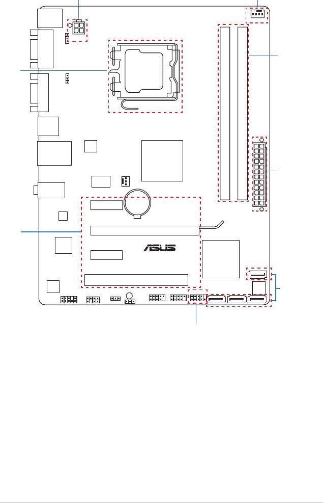
ASUS P5G41T-M LX3 PLUS 3
5
KBMS
CPU_FAN
ATX12V
KBPWR
COM1
USBPW1-4
LGA775
VGA
USB34
RTL
8103EL
LAN1_USB12
®
Intel
DDR3 DIMM_A1 (64bit, 240-pin module)
DDR3 DIMM_B1 (64bit, 240-pin module)
G41
CHA_FAN
ICS
9LRS954
AUDIO
Lithium Cell
PCIEX1_1
CMOS Power
EATXPWR
ATHEROS
8151
PCIEX16
Super
I/O
PCIEX1_2
®
Intel
P5G41T-M LX3 PLUS
ICH7
PCI1
SATA4
ALC887
8Mb
SPEAKER
SB_PWR
USB56 USB78
F_PANEL
BIOS
SATA1 SATA2
SPDIF_OUT
CLRTC
SATA3
AAFP
USBPW5-8
Step 7
Step 2
Step 3
Step 1
Step 7
Step 5
Step 4
Step 6
Step 1
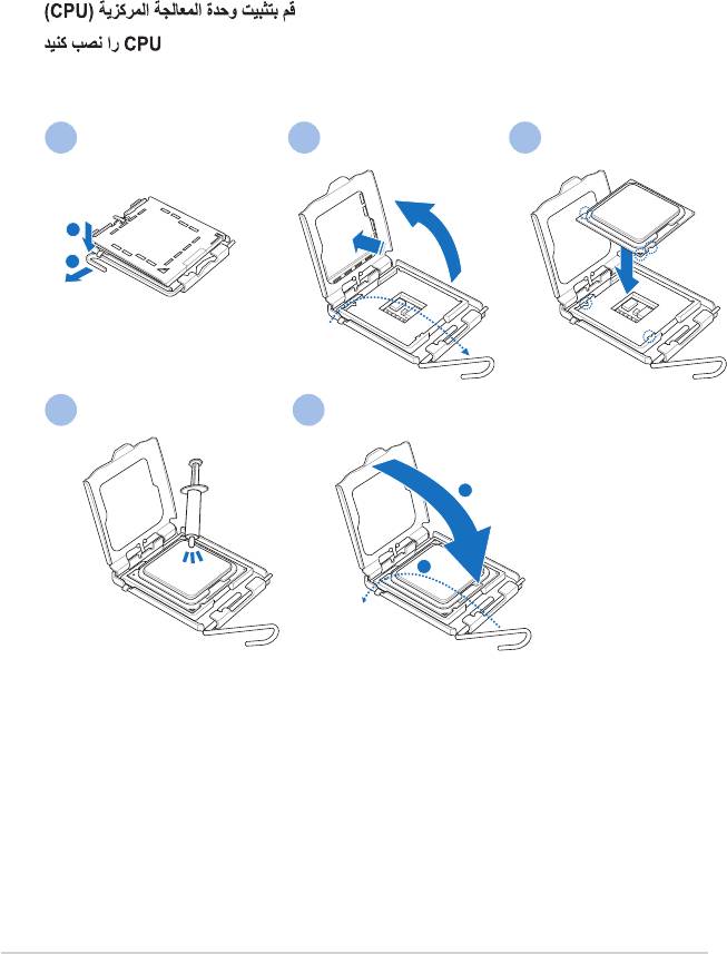
Installer le CPU
CPUを設置する
CPU 설치
ติดตั้ง CPU
Pasang CPU
Lắp CPU
CPU’yu takın
1 2 3
4 5
4 ASUS P5G41T-M LX3 PLUS
Step 2
Installer le ventilateur de CPU
CPUファン を設置する
CPU 팬 설치
ติดตั้งพัดลม CPU
Pasang kipas CPU
Lắp quạt CPU
CPU fanını takın
A
1 2
B
B
A
ASUS P5G41T-M LX3 PLUS 5
Step 3
Installer les modules mémoire
メモリーモジュールを設置する
메모리 모듈 설치
ติดตั้งโมดูลหน่วยความจำ
Pasang modul memori
Lắp các thanh nhớ
Bellek modüllerini takın
6 ASUS P5G41T-M LX3 PLUS
Step 4
Installer des périphériques SATA
SATA デバイスを取り付ける
SATA 장치 설치
ติดตั้งอุปกรณ์ SATA
Pasang perangkat SATA
Lắp các thiết bị SATA
SATA aygıtlarını takın
ASUS P5G41T-M LX3 PLUS 7
Step 5
Installer une carte d’extension
拡張カードを設置する
확장 카드 설치
ติดตั้งเอ็กซ์แพนชั่นการ์ด
Pasang kartu ekspansi
Lắp (các) thẻ mở rộng
Genişletme kartlarını takın
8 ASUS P5G41T-M LX3 PLUS
Step 6
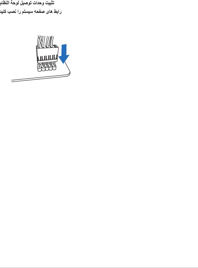
Installer les connecteurs système
システムパネルコネクターを取り付ける
시스템 패널 커넥터 설치
ติดตั้งขั้วต่อแผงระบบ
Pasang konektor panel sistem
Lắp các đầu nối hệ thống ra ngoài
Sistem paneli konnektörlerini takın
ASUS P5G41T-M LX3 PLUS 9
Step 7
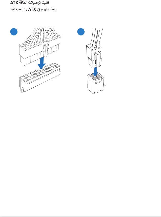
Installer les connecteurs d’alimentation ATX
ATX 電源コネクターを取り付ける
ATX 전원 커넥터 설치
ติดตั้งขั้วต่อ ATX เพาเวอร์
Pasang konektor daya ATX
Lắp các đầu nối nguồn ATX
ATX güç konnektörlerini takın
21
10 ASUS P5G41T-M LX3 PLUS

Step 8
Allumer le système et installer le système d’exploitation et les pilotes
システムの電源をONにし、OSとドライバーをインストールする
시스템 전원 켜기 및 운영체제와 드라이버 설치
เปิดระบบ และติดตั้งระบบปฏิบัติการและไดรเวอร์
Hidupkan sistem, lalu instal sistem operasi dan driver
Bật nguồn hệ thống và cài đặt hệ điều hành cũng như các driver
Sistemi açıp işletim sistemini ve sürücüleri yükleyin
21
ASUS P5G41T-M LX3 PLUS 11

www.asus.com
15060-1370B000