-
Contents
-
Table of Contents
-
Bookmarks
Quick Links
Related Manuals for Asus M2N-MX SE
Summary of Contents for Asus M2N-MX SE
-
Page 1
M2N-MX SE… -
Page 2
Product warranty or service will not be extended if: (1) the product is repaired, modified or altered, unless such repair, modification of alteration is authorized in writing by ASUS; or (2) the serial number of the product is defaced or missing. -
Page 3: Table Of Contents
Contents Notices … vi Safety information …vii M2N-MX SE specifications summary …viii Chapter 1: Product introduction Welcome! … 1-2 Package contents … 1-2 Special features … 1-2 1.3.1 Product highlights … 1-2 1.3.2 Innovative ASUS features … 1-5 Before you proceed … 1-6 Motherboard overview …
-
Page 4
Creating a bootable floppy disk … 2-2 ASUS EZ Flash utility … 2-3 2.1.2 2.1.3 AFUDOS utility … 2-4 2.1.4 ASUS CrashFree BIOS 2 utility … 2-6 2.1.5 ASUS Update utility … 2-8 BIOS setup program … 2-11 2.2.1 BIOS menu screen … 2-12 2.2.2… -
Page 5
Running the support CD … 3-2 3.2.2 Drivers menu … 3-3 3.2.3 Utilities menu … 3-4 3.2.4 Make Disk menu … 3-5 3.2.5 Manual menu … 3-6 3.2.6 ASUS Contact information … 3-7 3.2.7 Other information … 3-7 Creating a RAID driver disk … 3-9… -
Page 6: Notices
Notices Federal Communications Commission Statement This device complies with Part 15 of the FCC Rules. Operation is subject to the following two conditions: • This device may not cause harmful interference, and • This device must accept any interference received including interference that may cause undesired operation.
-
Page 7: Safety Information
Safety information Electrical safety • To prevent electrical shock hazard, disconnect the power cable from the electrical outlet before relocating the system. • When adding or removing devices to or from the system, ensure that the power cables for the devices are unplugged before the signal cables are connected.
-
Page 8: M2N-Mx Se Specifications Summary
M2N-MX SE specifications summary Chipset Front Side Bus Memory Expansion slots Graphics Storage High Definition Audio Special features viii Support AMD socket AM2 for AMD Athlon™ 64/ Athlon™ FX/Athlon™ X2/Sempron processors AMD64 architecture enables simultaneous 32-bit and 64-bit Supports AMD Cool ‘n’ Quiet™ Technology AMD Live!™…
-
Page 9
M2N-MX SE specifications summary Manageability BIOS features Rear panel Internal Connector Accessories Form Factor Support CD contents *Specifications are subject to change without notice. 4Mb Flash ROM, AMI BIOS, PnP, DMI2.0, WfM2.0, SM BIOS 2.3, ACPI 2.0 1 x Parallel port 1 x LAN (RJ-45) port 4 x USB 2.0 ports… -
Page 11: Chapter 1: Product Introduction
This chapter describes the motherboard features and the new technologies it supports. Product introduction…
-
Page 12: Welcome
T h a n k y o u f o r b u y i n g a n A S U S The motherboard delivers a host of new features and latest technologies, making it another standout in the long line of ASUS quality motherboards! Before you start installing the motherboard, and hardware devices on it, check the items in your package with the list below.
-
Page 13
PCI bus. PCI Express features point-to-point serial interconnections between devices and allows higher clockspeeds by carrying data in packets. This high speed interface is software compatible with existing PCI specifications. See page 1-20 for details. ASUS M2N-MX SE Gigabit and NVIDIA MediaShield storage ®… -
Page 14
Serial ATA 3Gb/s technology The motherboard supports next-generation SATA hard drives based on the new SATA 3Gb/s storage specification. The onboard NVIDIA nForce 430 ® MCP southbridge allows RAID 0, RAID 1, and JBOD configurations for two SATA connectors. USB 2.0 technology The motherboard implements the Universal Serial Bus (USB) 2.0 specification, dramatically increasing the connection speed from the 12 Mbps bandwidth on USB 1.1 to a fast 480 Mbps on USB 2.0. -
Page 15: Innovative Asus Features
ASUS EZ Flash With the ASUS EZ Flash, you can easily update the system BIOS even before loading the operating system. No need to use a DOS-based utility or boot from a floppy disk. See page 2-3 for details.
-
Page 16: Before You Proceed
This is a reminder that you should shut down the system and unplug the power cable before removing or plugging in any motherboard component. The illustration below shows the location of the onboard LED. M2N-MX SE Onboard LED M2N-MX SE Standby Power…
-
Page 17: Motherboard Overview
PS/2KBMS T : Mouse B: Keyboard ATX12V USB34 PS2_USBPW1-4 Attansic LAN_USB12 AUDIO Super I/O BIOS ALC662 SPDIF_OUT AAFP ASUS M2N-MX SE 19.3cm (7.6in) M2N-MX SE CPU_FAN PCIEX16 CLRTC CR2032 3V Lithium Cell CMOS Power Nvidia MCP61P SB_PWR PCI1 PCI2 FLOPPY…
-
Page 18: Placement Direction
Place six (6) screws into the holes indicated by circles to secure the motherboard to the chassis. Do not overtighten the screws! Doing so can damage the motherboard. Place this side towards the rear of the chassis M2N-MX SE Chapter 1: Product introduction…
-
Page 19: Central Processing Unit (Cpu)
1.6.1 Installing the CPU To install a CPU. Locate the CPU socket on the motherboard. M2N-MX SE M2N-MX SE CPU Socket AM2 Unlock the socket by pressing the lever sideways, then lift it up to a 90°-100° angle. Make sure that the socket lever is lifted up to 90°-100° angle, otherwise the CPU does not fit in completely.
-
Page 20
Connect the CPU fan cable to the CPU_FAN connector on the motherboard. M2N-MX SE M2N-MX SE CPU Fan Connector Do not forget to connect the CPU fan connector! Hardware monitoring errors can occur if you fail to plug this connector. -
Page 21: Installing The Heatsink And Fan
Your boxed CPU heatsink and fan assembly should come with installation instructions for the CPU, heatsink, and the retention mechanism. If the instructions in this section do not match the CPU documentation, follow the latter. ASUS M2N-MX SE Retention bracket Retention bracket lock 1-11…
-
Page 22
Attach one end of the retention bracket to the retention module base. Align the other end of the retention bracket (near the retention bracket lock) to the retention module base. A clicking sound denotes that the retention bracket is in place. Make sure that the fan and heatsink assembly perfectly fits the retention mechanism… -
Page 23: System Memory
240-pin footprint compared to the 184-pin DDR DIMM. DDR2 DIMMs are notched differently to prevent installation on a DDR DIMM socket. The figure illustrates the location of the DDR2 DIMM sockets: M2N-MX SE M2N-MX SE 240-pin DDR2 DIMM Sockets Channel Channel A Channel B 1.7.2…
-
Page 24
DIMMs in all two sockets. Always use identical DDR2 DIMM pairs for dual-channel model. For optimum compatibility, we recommend that you obtain memory modules from the same vendor. Visit the ASUS website (www.asus. com) for the latest Qualified Vendors List. Qualified Vendors List… -
Page 25
M2YVD5G3H31P4I1C52 512MB VDATA M2GVD5G3H166I1C52 VDATA M2GVD5G3I41P6I1C52 VDATA M2GVD5G3I41C4I1C52 VDATA M2GVD5G3I4176I1C52 512MB AL6E8E63B-6E1K AL7E8E63B-6E1K 256MB Nanya NT256T64UH4A1FY-3C 512MB Nanya NT512T64U88A1BY-3C ASUS M2N-MX SE Brand SS/DS Component Elpida E2508AB-6E-E Kingston D6408TE8WL-27 Elpida E5108AE-6E-E(ECC) Kingston D6408TE8WL-3 Kingston D6408TEBGGL3U Samsung K4T51083QC Samsung K4T56083QF-ZCE6 Samsung… -
Page 26
A — Supports one module inserted in any slot for a single-channel memory configuration. B — Supports one pair of modules inserted into the yellow slots. Visit the ASUS website (www.asus.com) for the latest memory Qualified Vendor List (QVL). 1-16… -
Page 27: Installing A Dimm
Support the DIMM lightly with your fingers when pressing the retaining clips. The DIMM might get damaged when it flips out with extra force. Remove the DIMM from the socket. ASUS M2N-MX SE DDR2 DIMM notch Unlocked retaining clip DDR2 DIMM notch…
-
Page 28: Expansion Slots
Expansion slots In the future, you may need to install expansion cards. The following sub-sections describe the slots and the expansion cards that they support. Make sure to unplug the power cord before adding or removing expansion cards. Failure to do so may cause you physical injury and damage motherboard components.
-
Page 29: Standard Interrupt Assignments
When using PCI cards on shared slots, ensure that the drivers support “Share IRQ” or that the cards do not need IRQ assignments; otherwise, conflicts will arise between the two PCI groups, making the system unstable and the card inoperable. ASUS M2N-MX SE Standard Function System Timer Keyboard Controller…
-
Page 30: Pci Slots
1.8.3 PCI slots The PCI slots support cards such as a LAN card, SCSI card, USB card, and other cards that comply with PCI specifications. The figure shows a LAN card installed on a PCI slot. 1.8.4 PCI Express x16 slot This motherboard has supports PCI Express x16 graphic cards that comply with PCI Express…
-
Page 31: Jumpers
Removing the cap will cause system boot failure! M2N-MX SE M2N-MX SE Clear RTC RAM You do not need to clear the RTC when the system hangs due to overclocking. For system failure due to overclocking, use the C.P.R. (CPU Parameter Recall) feature.
-
Page 32
(the default is the Space Bar). This feature requires an ATX power supply that can supply at least 500 mA on the +5VSB lead, and a corresponding setting in the BIOS. PS2_USBPW1-4 M2N-MX SE M2N-MX SE USB Device Wake Up 1-22 Chapter 1: Product introduction… -
Page 33: 1.10 Connectors
4-channel/ 6-channel configuration, the function of this port becomes Front Speaker Out. Microphone port (pink). This port connects a microphone. Refer to the audio configuration table for the function of the audio ports in 2, 4, or 6,-channel configuration. ASUS M2N-MX SE GREEN LED Status Description No Link…
-
Page 34: 1.10.2 Internal Connectors
Pin 5 on the connector is removed to prevent incorrect cable connection when using an FDD cable with a covered Pin 5. M2N-MX SE M2N-MX SE Floppy Disk Drive Connector 1-24 Headset 4-speaker…
-
Page 35
Use the 80-conductor IDE cable for Ultra DMA 133/100/66 IDE devices. If any device jumper is set as “Cable-Select,” make sure all other device jumpers have the same setting. M2N-MX SE IDE Connector M2N-MX SE ASUS M2N-MX SE Mode Cable of device(s) connector Black Master… -
Page 36: Serial Ata Connectors
If you install Serial ATA hard disk drives, you can create a RAID RAID 1, and JBOD configuration through the onboard NVIDIA MediaShield™ controller. M2N-MX SE M2N-MX SE SATA Connectors Important note on Serial ATA Install the Windows Pack1 before using Serial ATA.
-
Page 37
Only CPU Fan connector supports Q-Fan function. M2N-MX SE M2N-MX SE CPU Fan Connector Digital audio connector (4-1 pin SPDIF_OUT) This connector is for an additional Sony/Philips Digital Interface (S/PDIF) port(s). Connect the S/PDIF module cable to this connector, then install the module to a slot opening at the back of the system chassis. -
Page 38: Usb Connectors
USB 2.0 specification that supports up to 480 Mbps connection speed. M2N-MX SE M2N-MX SE USB 2.0 Connectors Never connect a 1394 cable to the USB connectors. Doing so will damage the motherboard! The USB 2.0 module is purchased separately.
-
Page 39: Front Panel Audio Connector
Connect one end of the front panel audio I/O module cable to this connector. M2N-MX SE M2N-MX SE Front Panel Audio Connector • We recommend that you connect a high-definition front panel audio module to this connector to avail of the motherboard high-definition audio capability.
-
Page 40
• You must install a PSU with a higher power rating if you intend to install additional devices. M2N-MX SE M2N-MX SE ATX Power Connector 1-30 EATX12V +12V DC +12V DC +3 Volts… -
Page 41: Reset Button
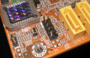
ON turns the system OFF. • Reset button This 2-pin connector is for the chassis-mounted reset button for system reboot without turning off the system power. ASUS M2N-MX SE PWR LED PWR BTN F_PANEL HD LED RESET 1-31…
-
Page 42
1-32 Chapter 1: Product introduction… -
Page 43
This chapter tells how to change the system settings through the BIOS Setup menus. Detailed descriptions of the BIOS parameters are also provided. BIOS setup… -
Page 44: Managing And Updating Your Bios
The following utilities allow you to manage and update the motherboard Basic Input/Output System (BIOS) setup. ASUS EZ Flash (Updates the BIOS in DOS mode using a floppy disk or the motherboard support CD.) ASUS AFUDOS (Updates the BIOS in DOS mode using a bootable floppy disk.)
-
Page 45: Asus Ez Flash Utility
2.1.2 ASUS EZ Flash utility The ASUS EZ Flash feature allows you to update the BIOS without having to go through the long process of booting from a floppy disk and using a DOS-based utility. The EZ Flash utility is built-in the BIOS chip so it is accessible by pressing <Alt>…
-
Page 46: Afudos Utility
Press <Enter>. The utility copies the current BIOS file to the floppy disk. A:\>afudos /oOLDBIOS1.rom AMI Firmware Update Utility — Version 1.19(ASUS V2.07(03.11.24BB)) Copyright (C) 2002 American Megatrends, Inc. All rights reserved. Reading flash … done Write to file… ok A:\>…
-
Page 47: Updating The Bios File
Updating the BIOS file To update the BIOS file using the AFUDOS utility: Visit the ASUS website (www.asus.com) and download the latest BIOS file for the motherboard. Save the BIOS file to a bootable floppy disk. Write the BIOS filename on a piece of paper. You need to type the exact BIOS filename at the DOS prompt.
-
Page 48: Asus Crashfree Bios 2 Utility
2.1.4 ASUS CrashFree BIOS 2 utility The ASUS CrashFree BIOS 2 is an auto recovery tool that allows you to restore the BIOS file when it fails or gets corrupted during the updating process. You can update a corrupted BIOS file using the motherboard support CD or the floppy disk that contains the updated BIOS file.
-
Page 49: Recovering The Bios From The Support Cd
Reading file “M2N-MXSE.ROM”. Completed. Start flashing… Restart the system after the utility completes the updating process. The recovered BIOS may not be the latest BIOS version for this motherboard. Visit the ASUS website (www.asus.com) to download the latest BIOS file. ASUS M2N-MX SE…
-
Page 50: Asus Update Utility
2.1.5 ASUS Update utility The ASUS Update is a utility that allows you to manage, save, and update the motherboard BIOS in Windows allows you to: • Save the current BIOS file • Download the latest BIOS file from the Internet •…
-
Page 51: Updating The Bios Through The Internet
Updating the BIOS through the Internet To update the BIOS through the Internet: Launch the ASUS Update utility from the Windows Start > Programs > ASUS > ASUSUpdate > ASUSUpdate. The ASUS Update main window appears. Select Update BIOS from…
-
Page 52: Updating The Bios Through A Bios File
Updating the BIOS through a BIOS file To update the BIOS through a BIOS file: Launch the ASUS Update utility from the Windows clicking Start > Programs > ASUS > ASUSUpdate > ASUSUpdate. The ASUS Update main window appears. Select Update BIOS from a file option from the drop-down menu, then click Next.
-
Page 53: Bios Setup Program
The BIOS setup screens shown in this section are for reference purposes only, and may not exactly match what you see on your screen. • Visit the ASUS website (www.asus.com) to download the latest BIOS file for this motherboard. ASUS M2N-MX SE…
-
Page 54: Bios Menu Screen
2.2.1 BIOS menu screen Menu items Menu bar System Time System Date Legacy Diskette A IDE Configuration Primary IDE Master Primary IDE Slave SATA1 SATA2 System Information Sub-menu items 2.2.2 Menu bar The menu bar on top of the screen has the following main items: Main For changing the basic system configuration Advanced…
-
Page 55: Menu Items
2.2.9 General help At the top right corner of the menu screen is a brief description of the selected item. ASUS M2N-MX SE System Time [11:10:19] Use [ENTER], [TAB] System Date [Thu 03/27/2003] or [SHIFT-TAB] to Legacy Diskette A [1.44M, 3.5 in]…
-
Page 56: Main Menu
Main menu When you enter the BIOS Setup program, the Main menu screen appears, giving you an overview of the basic system information. Refer to section “2.2.1 BIOS menu screen” for information on the menu screen items and how to navigate through them. System Time System Date Legacy Diskette A…
-
Page 57: Ide Configuration
<Enter> to display the IDE device information. Primary IDE Master Device : Not Detected Type LBA/Large Mode Block(Multi-sector Transfer) M PIO Mode DMA Mode SMART Monitoring 32Bit Data Transfer ASUS M2N-MX SE [Enabled] [Enabled] [Disabled] Enabled [Auto] [Auto] [Auto] [Auto] [Auto] [Auto]…
-
Page 58
The BIOS automatically detects the values opposite the dimmed items (Device, Vendor, Size, LBA Mode, Block Mode, PIO Mode, Async DMA, Ultra DMA, and SMART monitoring). These values are not user-configurable. These items show N/A if no IDE device is installed in the system. Type [Auto] Selects the type of IDE drive. -
Page 59: Sata1 And Sata2
When set to [Disabled], the data transfer from and to the device occurs one sector at a time. Configuration options: [Disabled] [Auto] ASUS M2N-MX SE [Auto] [Auto] [Auto]…
-
Page 60: System Information
PIO Mode [Auto] Selects the PIO mode. Configuration options: [Auto] [0] [1] [2] [3] [4] DMA Mode [Auto] Selects the DMA mode. Configuration options: [Auto] [SWDMA0] [SWDMA1] [SWDMA2] [MWDMA0] [MWDMA1] [MWDMA2] [UDMA0] [UDMA1] [UDMA2] [UDMA3] [UDMA4] [UDMA5] SMART Monitoring [Auto] Sets the Smart Monitoring, Analysis, and Reporting Technology.
-
Page 61: Advanced Menu
Cool’n’Quiet AMD Overclocking Configuration GART Error Reporting [Disabled] This option should remain disabled for the normal operation. The driver developer may enable it for testing purpose. Configuration options: [Disabled] [Enabled] ASUS M2N-MX SE [Disabled] [Enabled] [Enabled] [Enabled] This option should remain disabled for the normal operation.
-
Page 62
Microcode Updation [Enabled] Allows you to enable or disable the microcode updation. Configuration options: [Continuous] [Discrete] Secure Virtual Machine [Enabled] Allows you to enable or disable the AMD Secure Virtual Machine. Configuration options: [Disabled] [Enabled] Cool‘n’Quiet [Enabled] Allows you to enable or disable the generation of ACPI_PPC, _PSS, and _PCT objects. -
Page 63: Chipset
Select the DRAM Frequency programming method. If Auto, the DRAM speed will be based on SPDs. If Limit, the DRAM speed will not exceed the specified value. If Manual, the DRAM specified will be programmed regardless. Configuration options: [Auto] [Limit] [Manual] ASUS M2N-MX SE malfunction. [Auto] [Auto] [Auto]…
-
Page 64
CAS Latency (CL) [Auto] Sets the CAS latency timing. Configuration options: [Auto] [3.0] [4.0] [5.0] [6.0] TRCD [Auto] Sets the RAS-to-CAS delay timing. Configuration options: [Auto] [3 CLK] [4 CLK] [5 CLK] [6 CLK] TRP [Auto] Sets the row-precharge delay timing. Configuration options: [Auto] [3 CLK] [4 CLK] [5 CLK] [6 CLK] TRAS [Auto] Sets the row-active delay timing. -
Page 65
Allows the L1 Data Cache ram to be corrected while idle. Configuration options: [Disabled] [40ns] [80ns] [160ns] [320ns] [640ns] [1.28us] [2.56us] [5.12us] [10.2us] [20.5us] [41.0us] [81.9us] [163.8us] [327.7us] [655.4us][1.31ms] [2.62ms] [5.24ms] [10.49ms] [20.97ms] [42.00ms] [84.00ms] ASUS M2N-MX SE [Enabled] [Disabled] [Disabled] [Disabled]… -
Page 66: Southbridge Configuration
Power Down Control [Auto] Allows DIMMs to enter power down mode by deasserting the clock enable signal when DIMMs are not in use. Configuration options: [Auto] [Disabled] SouthBridge Configuration SouthBridge MCP61 chipset Configuration Primary Graphics Adapter OnChip VGA Frame Buffer Size AZALIA Audio Front Panel Select OnBoard LAN…
-
Page 67: Onboard Devices Configuration
ECP Mode DMA Channel [DMA3] Appears only when the Parallel Port Mode is set to [ECP]. This item allows you to set the Parallel Port ECP DMA. Configuration options: [DMA0] [DMA1] [DMA3] ASUS M2N-MX SE [Disabled] [1000 MHz] [16 16] ↓…
-
Page 68: Pci Pnp
Parallel Port IRQ [IRQ7] Configuration options: [IRQ5] [IRQ7] 2.4.4 PCI PnP The PCI PnP menu items allow you to change the advanced settings for PCI/PnP devices. The menu includes setting IRQ and DMA channel resources for either PCI/PnP or legacy ISA devices, and setting the memory size block for legacy ISA devices.
-
Page 69: Usb Configuration
Configuration options: [Disabled] [Enabled] [Auto] USB 2.0 Controller Mode [HiSpeed] Allows you to configure the USB 2.0 controller in HiSpeed (480 Mbps) or Full Speed (12 Mbps). Configuration options: [HiSpeed] [Full Speed] ASUS M2N-MX SE [Enabled] [Enabled] [Enabled] [HiSpeed]…
-
Page 70: Usb Mass Storage Device Configuration
USB Mass Storage Device Configuration USB Mass Storage Device Configuration USB Mass Storage Reset Delay Device #1 Emulation Type USB Mass Storage Reset Delay [20 Sec] Allows you to set the numbers of seconds POST waits for the USB mass storage device after start unit command. Configuration options: [10 Sec] [20 Sec] [30 Sec] [40 Sec] Emulation Type [Auto] Allows selection of the emulation type.
-
Page 71: Power Menu
Allows you to enable or disable the Advanced Configuration and Power Interface (ACPI) support in the Application-Specific Integrated Circuit (ASIC). When set to Enabled, the ACPI APIC table pointer is included in the RSDT pointer list. Configuration options: [Disabled] [Enabled] ASUS M2N-MX SE [Auto] [Disabled] [Enabled]…
-
Page 72: Apm Configuration
2.5.4 APM Configuration APM Configuration Power Button Mode Restore on AC Power Loss Power On By PCI Device Power On By Ring Power On By PS/2 KB/MS Power On By RTC Alarm Power Button Mode [On/Off] Allows the system to go into On/Off mode or suspend mode when the power button is pressed.
-
Page 73: Hardware Monitor
The onboard hardware monitor automatically detects the voltage output through the onboard voltage regulators. Smart Q-Fan Function [Disabled] Allows you to enable or disable the ASUS Q-Fan feature that smartly adjusts the fan speeds for more efficient system operation. Configuration options: [Disabled] [Enabled] ASUS M2N-MX SE [44ºC/111ºF]…
-
Page 74: Boot Menu
Boot menu The Boot menu items allow you to change the system boot options. Select an item then press <Enter> to display the sub-menu. Boot settings Boot Device Priority Removable Drives Boot Settings Configuration Security 2.6.1 Boot Device Priority Boot Device Priority 1st Boot Device 2nd Boot Device 3rd Boot Device…
-
Page 75: Boot Settings Configuration
This allows you to enable or disable the full screen logo display feature. Configuration options: [Disabled] [Enabled] Set this item to [Enabled] to use the ASUS MyLogo2™ feature. Add On ROM Display Mode [Force BIOS] Sets the display mode for option ROM.
-
Page 76: Security
Hit ‘DEL’ Message Display [Enabled] When set to Enabled, the system displays the message “Press DEL to run Setup” during POST. Configuration options: [Disabled] [Enabled] Interrupt 19 Capture [Disabled] When set to [Enabled], this function allows the option ROMs to trap Interrupt 19.
-
Page 77: Change User Password
When set to [Setup], BIOS checks for user password when accessing the Setup utility. When set to [Always], BIOS checks for user password both when accessing Setup and booting the system. Configuration options: [Setup] [Always] ASUS M2N-MX SE [Full Access] [Setup] Select Screen…
-
Page 78: Exit Menu
Exit menu The Exit menu items allow you to load the optimal or failsafe default values for the BIOS items, and save or discard your changes to the BIOS items. Exit Options Exit & Save Changes Exit & Discard Changes Discard Changes Load Setup Defaults Pressing <Esc>…
-
Page 79: Chapter 3: Software Support
This chapter describes the contents of the support CD that comes with the motherboard package. Software support…
-
Page 80: Installing An Operating System
The contents of the support CD are subject to change at any time without notice. Visit the ASUS website(www.asus.com) for updates. 3.2.1 Running the support CD Place the support CD to the optical drive.
-
Page 81: Drivers Menu
The drivers menu shows the available device drivers if the system detects installed devices. Install the necessary drivers to activate the devices. ASUS Installl-Drivers Installation Wizard Installs the ASUS Install-Drivers Installation Wizard. NVIDIA Chipset Driver Program Installs the NVIDIA nForce™ Chipset Driver program.
-
Page 82: Utilities Menu
3.2.3 Utilities menu The Utilities menu shows the applications and other software that the motherboard supports. ADOBE Acrobat Reader V7.0 The Adobe Acrobat ® documents in Portable Document Format (PDF). Microsoft DirectX 9.0c The Microsoft DirectX ® computer graphics and sounds. DirectX of your computer so you can enjoy watching TV and movies, capturing videos, or playing games on your computer.
-
Page 83: Make Disk Menu
Make Disk menu The Make Disk menu allows you to make a RAID driver disk. NVIDIA 32bit SATA RAID Driver ® Allows you to create an NVIDIA 32-bit system. ASUS M2N-MX SE Serial ATA (SATA) RAID driver disk for a ®…
-
Page 84: Manual Menu
3.2.5 Manual menu The Manual menu contains a list of supplementary user manuals. Click an item to open the folder of the user manual. Most user manual files are in Portable Document Format (PDF). Install the Adobe user manual file. NVIDIA SATA RAID User’s Manual ®…
-
Page 85: Asus Contact Information
3.2.6 ASUS Contact information Click the Contact tab to display the ASUS contact information. You can also find this information on the inside front cover of this user guide. 3.2.7 Other information The icons on the top right corner of the screen give additional information on the motherboard and the contents of the support CD.
-
Page 86: Technical Support Form
Browse this CD Displays the support CD contents in graphical format. Technical support Form Displays the ASUS Technical Support Request Form that you have to fill out when requesting technical support. Filelist Displays the contents of the support CD and a brief description of each in text format.
-
Page 87: Creating A Raid Driver Disk
Follow the succeeding screen instructions to complete the installation. Due to chipset limitation, the Serial ATA ports supported by the NVIDIA chipset doesn’t support Serial Optical Disk Drives (Serial ODD) under DOS. ASUS M2N-MX SE ® RAID configuration, refer to the ®…
-
Page 88
3-10 Chapter 3: Software support…
Руководства пользователя
Версия T4204
1.97 MB
Motherboard Installation Guide (Traditional Chinese)
Версия C4204
1.83 MB
Motherboard Installation Guide (Simplified Chinese)
Версия QJ4204
1.68 MB
Motherboard Installation Guide (Japanese)
Версия QG4204
1.6 MB
Motherboard Installation Guide (German)
Версия QF4204
1.59 MB
Motherboard Installation Guide (French)
Версия Q4204
43.39 MB
Motherboard Installation Guide (Multiple Languages)
Версия A3168
4.4 MB
M2N-MX SE Quick Start Guide for Multiple Languages
Версия F3353
2.32 MB
M2N-MX SE user’s manual(French)
Версия G3168
2.07 MB
M2N-MX SE user’s manual(German)
Версия E3168
3.47 MB
M2N-MX SE user’s manual (English)
Версия C3168
2.15 MB
M2N-MX SE user’s manual (Simplified Chinese)
Версия T3168
2.32 MB
M2N-MX SE user’s manual (Traditional Chinese)
Версия T2437
2.57 MB
Motherboard DIY Troubleshooting Guide (Traditional Chinese version)
-
Драйверы
16
-
Инструкции по эксплуатации
12
Языки:

ASUS M2N-MX SE инструкция по эксплуатации
(88 страниц)
- Языки:Английский
-
Тип:
PDF -
Размер:
3.55 MB -
Описание:
M2N-MX SE user’s manual (English)
Просмотр

ASUS M2N-MX SE инструкция по эксплуатации
(40 страниц)
- Языки:Молдавский, Немецкий
-
Тип:
PDF -
Размер:
1.65 MB -
Описание:
Motherboard Installation Guide (German)
Motherboard Installation Guide (German)
Просмотр

ASUS M2N-MX SE инструкция по эксплуатации
(90 страниц)
- Языки:Китайский
-
Тип:
PDF -
Размер:
2.41 MB -
Описание:
M2N-MX SE user’s manual (Traditional Chinese)
Просмотр

ASUS M2N-MX SE инструкция по эксплуатации
(90 страниц)
- Языки:Французский
-
Тип:
PDF -
Размер:
2.86 MB -
Описание:
M2N-MX SE user’s manual(French)
Просмотр

ASUS M2N-MX SE инструкция по эксплуатации
(88 страниц)
- Языки:Немецкий
-
Тип:
PDF -
Размер:
2.15 MB -
Описание:
M2N-MX SE user’s manual(German)
Просмотр

ASUS M2N-MX SE инструкция по эксплуатации
(44 страницы)
- Языки:Китайский, Молдавский
-
Тип:
PDF -
Размер:
1.88 MB -
Описание:
Motherboard Installation Guide (Simplified Chinese)
Просмотр

ASUS M2N-MX SE инструкция по эксплуатации
(44 страницы)
- Языки:Китайский, Молдавский
-
Тип:
PDF -
Размер:
2.02 MB -
Описание:
Motherboard Installation Guide (Traditional Chinese)
Просмотр

ASUS M2N-MX SE инструкция по эксплуатации
(8 страниц)
- Языки:Китайский, Молдавский
-
Тип:
PDF -
Размер:
2.67 MB -
Описание:
Motherboard DIY Troubleshooting Guide (Traditional Chinese version)
Просмотр

ASUS M2N-MX SE инструкция по эксплуатации
(40 страниц)
- Языки:Молдавский, Японский
-
Тип:
PDF -
Размер:
1.73 MB -
Описание:
Motherboard Installation Guide (Japanese)
Просмотр

ASUS M2N-MX SE инструкция по эксплуатации
(40 страниц)
- Языки:Молдавский, Французский
-
Тип:
PDF -
Размер:
1.64 MB -
Описание:
Motherboard Installation Guide (French)
Просмотр

ASUS M2N-MX SE инструкция по эксплуатации
(721 страница)
- Языки:Молдавский
-
Тип:
PDF -
Размер:
43.88 MB -
Описание:
Motherboard Installation Guide (Multiple Languages)
Просмотр

ASUS M2N-MX SE инструкция по эксплуатации
(29 страниц)
-
Тип:
PDF -
Размер:
4.45 MB -
Описание:
M2N-MX SE Quick Start Guide for Multiple Languages
Просмотр
На NoDevice можно скачать инструкцию по эксплуатации для ASUS M2N-MX SE. Руководство пользователя необходимо для ознакомления с правилами установки и эксплуатации ASUS M2N-MX SE. Инструкции по использованию помогут правильно настроить ASUS M2N-MX SE, исправить ошибки и выявить неполадки.
Краткое содержание страницы № 1
M2N-MX SE
Motherboard
Краткое содержание страницы № 2
E3168 First Edition V1 April 2007 Copyright © 2007 ASUSTeK COMPUTER INC. All Rights Reserved. No part of this manual, including the products and software described in it, may be reproduced, transmitted, transcribed, stored in a retrieval system, or translated into any language in any form or by any means, except documentation kept by the purchaser for backup purposes, without the express written permission of ASUSTeK COMPUTER INC. (“ASUS”). Product warranty or service will not be extended i
Краткое содержание страницы № 3
Contents Notices …………………………………………………………………………………… vi Safety information ……………………………………………………………………vii M2N-MX SE specifications summary ……………………………………………viii Chapter 1: Product introduction 1.1 Welcome! …………………………………………………………………… 1-2 1.2 Package contents ……………………………………..
Краткое содержание страницы № 4
Contents Chapter 2: BIOS setup 2.1 Managing and updating your BIOS …………………………………. 2-2 2.1.1 Creating a bootable floppy disk ………………………… 2-2 2.1.2 ASUS EZ Flash utility ……………………………………….. 2-3 2.1.3 AFUDOS utility ……………………………………………….. 2-4 2.1.4 ASUS CrashFree BIOS 2 utility ………………………….. 2-6 2.1.5 ASUS Update utility ………………………………………… 2-8 2
Краткое содержание страницы № 5
Contents 2.5.4 APM Configuration ………………………………………… 2-30 2.5.5 Hardware Monitor ………………………………………….. 2-31 2.6 Boot menu ……………………………………………………………….. 2-32 2.6.1 Boot Device Priority ………………………………………. 2-32 2.6.2 Removable drives ………………………………………….. 2-32 2.6.3 Boot Settings Configuration …………………………… 2-33 2.6.4 Sec
Краткое содержание страницы № 6
Notices Federal Communications Commission Statement This device complies with Part 15 of the FCC Rules. Operation is subject to the following two conditions: • This device may not cause harmful interference, and • This device must accept any interference received including interference that may cause undesired operation. This equipment has been tested and found to comply with the limits for a Class B digital device, pursuant to Part 15 of the FCC Rules. These limits are designed to provide r
Краткое содержание страницы № 7
Safety information Electrical safety • To prevent electrical shock hazard, disconnect the power cable from the electrical outlet before relocating the system. • When adding or removing devices to or from the system, ensure that the power cables for the devices are unplugged before the signal cables are connected. If possible, disconnect all power cables from the existing system before you add a device. • Before connecting or removing signal cables from the motherboard, ensure that all power
Краткое содержание страницы № 8
M2N-MX SE specifications summary CPU Support AMD socket AM2 for AMD Athlon™ 64/ Athlon™ FX/Athlon™ X2/Sempron processors AMD64 architecture enables simultaneous 32-bit and 64-bit Supports AMD Cool ‘n’ Quiet™ Technology AMD Live!™ Ready ® Chipset NVIDIA nForce 430/GeForce6100 2000/1600 MT/s Front Side Bus Memory Dual-channel memory architecture 2 x 240-pin DIMM, support max 2 GB unbufferred ECC and non-ECC 800/667/533 MHz DDR2 memory modules Expansion slots 1 x
Краткое содержание страницы № 9
M2N-MX SE specifications summary Manageability BIOS features 4Mb Flash ROM, AMI BIOS, PnP, DMI2.0, WfM2.0, SM BIOS 2.3, ACPI 2.0 Rear panel 1 x Parallel port 1 x LAN (RJ-45) port 4 x USB 2.0 ports 1 x VGA port 1 x COM1 port 1 x PS/2 keyboard port 1 x PS/2 mouse port 1 x 5.1-channel audio ports Internal Connector 2 x USB 2.0 connector supports additional 4 USB 2.0 ports 1 x S/PDIF output connector 1 x High Definition Front panel audio connector 1 x 4-pin CPU Fan / 1
Краткое содержание страницы № 10
x
Краткое содержание страницы № 11
This chapter describes the motherboard features and the new technologies it supports. Product 1 introduction
Краткое содержание страницы № 12
1.1 Welcome! ® Thank you for buying an ASUS M2N-MX SE motherboard! The motherboard delivers a host of new features and latest technologies, making it another standout in the long line of ASUS quality motherboards! Before you start installing the motherboard, and hardware devices on it, check the items in your package with the list below. 1.2 Package contents Check your motherboard package for the following items. Motherboard ASUS M2N-MX SE motherboard Cables 1 x Serial ATA signal cables 1 x
Краткое содержание страницы № 13
AMD Cool ‘n’ Quiet Technology The motherboard supports the AMD Cool ‘n’ Quiet Technology, which monitors system operation and automatically adjusts CPU voltage and frequency for a cool and quiet operating environment. ® NVIDIA GeForce™ 6100 GPU ® and NVIDIA nForce™ 430 MCP chipsets ® The NVIDIA GeForce™ 6100 graphics processing unit (GPU) Northbridge ® supports Microsoft DirectX 9.0 Shader Model 3.0, and PCI Express interface. ® The NVIDIA nForce™ 430 media and communications proces
Краткое содержание страницы № 14
Serial ATA 3Gb/s technology The motherboard supports next-generation SATA hard drives based on the ® new SATA 3Gb/s storage specification. The onboard NVIDIA nForce 430 MCP southbridge allows RAID 0, RAID 1, and JBOD configurations for two SATA connectors. USB 2.0 technology The motherboard implements the Universal Serial Bus (USB) 2.0 specification, dramatically increasing the connection speed from the 12 Mbps bandwidth on USB 1.1 to a fast 480 Mbps on USB 2.0. USB 2.0 is backw
Краткое содержание страницы № 15
1.3.2 Innovative ASUS features ASUS CrashFree BIOS 2 This feature allows you to restore the original BIOS data from the support CD in case when the BIOS codes and data are corrupted. This protection eliminates the need to buy a replacement BIOS chip. See page 2-6 for details. ASUS EZ Flash With the ASUS EZ Flash, you can easily update the system BIOS even before loading the operating system. No need to use a DOS-based utility or boot from a floppy disk. See page 2-3 for details.
Краткое содержание страницы № 16
1.4 Before you proceed Take note of the following precautions before you install motherboard components or change any motherboard settings. • Unplug the power cord from the wall socket before touching any component. • Use a grounded wrist strap or touch a safely grounded object or a metal object, such as the power supply case, before handling components to avoid damaging them due to static electricity • Hold components by the edges to avoid touching the ICs on them. • Whenever you uninstall
Краткое содержание страницы № 17
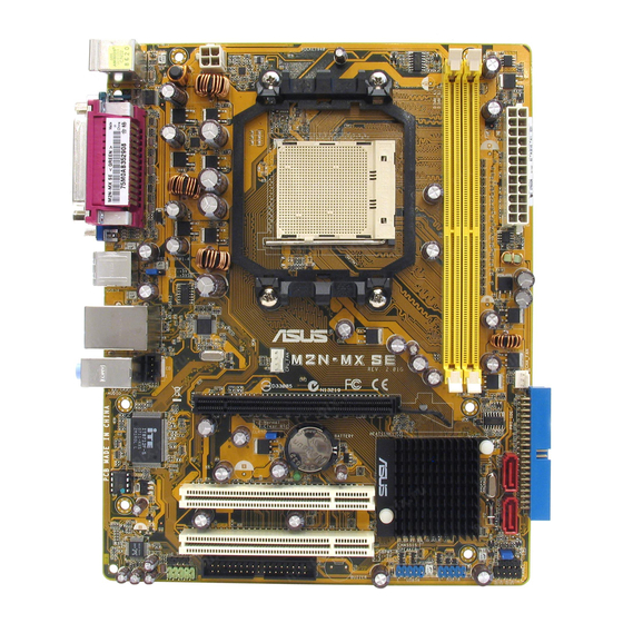
1.5 Motherboard overview 1.5.1 Motherboard layout 19.3cm (7.6in) PS/2KBMS T: Mouse B: Keyboard ATX12V USB34 PS2_USBPW1-4 Attansic LAN_USB12 R F2 M2N-MX SE AUDIO CPU_FAN PCIEX16 CLRTC CR2032 3V Super I/O Lithium Cell CMOS Power Nvidia MCP61P SB_PWR 4Mb BIOS PCI1 PCI2 USBPW5-8 ALC662 SPDIF_OUT SPEAKER AAFP USB56 USB78 FLOPPY F_PANEL ASUS M2N-MX SE 1-7 VGA COM1 PARALLEL PORT CD Socket AM2 DDR2 DIMM_A1 (64 bit,240-pin module) DDR2 DIMM_B1 (64 bit,240-pin module) SATA1 SATA2 CHA_ FAN EATXPWR PRI_IDE
Краткое содержание страницы № 18
1.5.2 Placement direction When installing the motherboard, make sure that you place it into the chassis in the correct orientation. The edge with external ports goes to the rear part of the chassis as indicated in the image below. 1.5.3 Screw holes Place six (6) screws into the holes indicated by circles to secure the motherboard to the chassis. Do not overtighten the screws! Doing so can damage the motherboard. Place this side towards the rear of the chassis R M2N-MX SE 1-8 Chapter 1: Produ
Краткое содержание страницы № 19
1.6 Central Processing Unit (CPU) The motherboard comes with a 940-pin AM2 socket designed for the AMD Athlon™ 64 X2/Athlon™ 64/Athlon™ FX/Sempron™ processor. The AM2 socket has a different pinout from the 940-pin socket designed for the AMD Opteron™ processor. Make sure you use a CPU is designed for the AM2 socket. The CPU fits in only one correct orientation. DO NOT force the CPU into the socket to prevent bending the connectors on the socket and damaging the CPU! 1.6.1 Installing the C
Краткое содержание страницы № 20
3. Position the CPU above the socket such that the CPU corner with the gold triangle matches the socket corner with a small triangle. 4. Carefully insert the CPU into the socket until it fits in place. Small triangle Gold triangle The CPU fits only in one correct orientation. DO NOT force the CPU into the socket to prevent bending the pins and damaging the CPU! 5. When the CPU is in place, push down the socket lever to secure the CPU. The lever clicks on the side tab to indicate that i
На чтение 7 мин Просмотров 1.9к. Опубликовано 24.10.2020
Содержание
- Шаг 1 — находим шлейфы, идущие от передней панели к мат. плате
- Шаг 2 — находим контакты на материнской плате для подключения передней панели
- Шаг 3 — Подключаем фишки разъемов передней панели к соответствующим разъемам материнской платы
- Вариант первый
- Вариант второй
- Нет звука через HDMI: устройство уже используется другим приложением
- CLRTC на материнской плате asus что это?
- jcom1 на материнской плате что это?
- 3 Комментариев
- Александр
- Страница скачивания руководства по обслуживанию Asus M2N-MX
Большинство неопытных компьютерных пользователей считают, что подключить переднюю панель корпуса компьютера, на которой находятся кнопки включения и перезагрузки компьютера, а также USB входы и аудио выходы, к материнской плате является сложным и трудно выполнимым занятием.
Но, как часто это бывает, потратив 5 минут на изучение вопроса, все становится понятно и очень даже выполнимо. В данной статье мы рассмотрим последовательность действий, которые необходимо выполнить для успешного и правильного подключения передней панели к к материнской плате, будь это плата фирмы Asus, Gigabyte, Asrock, MSI и других.
Шаг 1 — находим шлейфы, идущие от передней панели к мат. плате
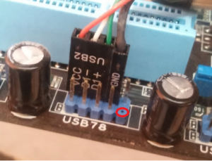
Это те самые шлейфы, которые мы будем подключать к соответствующим разъемам материнской платы. Особенность этих самых шлейфов, по которым их можно найти среди других проводов в корпусе системного блока это надписи на концах их разъемов:
- Power SW (PWRBTN) — Кнопка включения компьютера;
- Reset SW (Reset) — Кнопка перезагрузки;
- HDD LED ( >

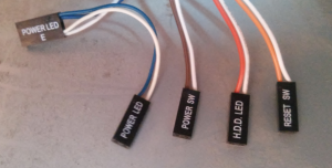
Разъемы передней панели системного блока
Для тех, у кого Power LED состоит из 2-ух фишек на 2 и 3 контакта (как на рисунке выше) обоснование следующее: на некоторых материнских платах разъем подключения POWER LED (индикатор включения компьютера) выполнен на 3-ех контактах (средний не используется), а на некоторых на 2-ух. Поэтому в вашем случае нужно использовать либо одну фишку Power Led, либо другую.
Шаг 2 — находим контакты на материнской плате для подключения передней панели
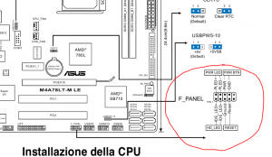
Стоит отметить, что подключение кнопок включения, перезагрузки, индикатора работы жесткого диска и индикатора включения компьютера, а также спикера (F_Panel) это одна группа разъемов (1 на рисунке ниже), подключение передних USB (USB) — другая группа (2 на рисунке ниже) и разъемы наушников с микрофоном (AAFP) — третья (3 на рисунке ниже).
На материнской плате они расположены примерно вот так:
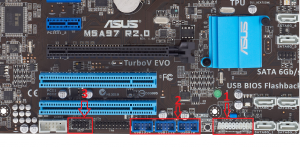
Расположение разъемов на материнской плате для подключения передней панели системного блока
Шаг 3 — Подключаем фишки разъемов передней панели к соответствующим разъемам материнской платы
Далее возможны 2 варианта развития ситуации.
Вариант первый
На вашей материнской плате все контакты подписаны и вы просто одеваете фишки на контакты соблюдая соответствующие названия и полярность. Полярность важна для HDD LED (IDE LED) и Power LED. На плате плюсовой контакт подписан как «+», а на фишке плюсовой контакт это цветной провод (отличный от белого и черного). Либо же если все провода от передней панели черного цвета, то на них «+» тоже будет подписан.
Полярность + и — при подключении PLED и HDLED
Даже если вы перепутаете полярность, то ничего страшного не произойдет. Просто на просто при включении не будет загораться кнопка включения и не будет моргать светодиод активности жесткого диска. В этом случае просто переверните не работающую фишку вверх ногами на контактах мат. платы, чтобы поменять полярность.
Вариант второй
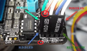
Контакты на материнской плате не подписаны, как на фото ниже.
Контакты подключения передней панели на материнской плате без подписей
В этом случае вам нужно определить модель своей материнской платы, найти ее в интернете и посмотреть документацию по распиновке контактов кнопок, индикаторов, usb и звуковым выходам.
Инструкция со схемой подключения передней панели к материнской плате
Подключение передних аудио выходов и микрофона
особенности соблюдения полярности при подключении передней папнели
Подключение передних USB входов к материнской плате

Разъемы и кабели
Нет звука через HDMI: устройство уже используется другим приложением
Разъемы и кабели
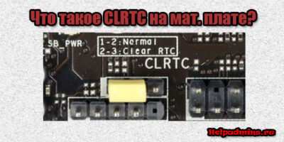
CLRTC на материнской плате asus что это?

Разъемы и кабели
jcom1 на материнской плате что это?
3 Комментариев
Александр
Сайт датирован 2018 годом, а фрагменты мам c разъёмами и др.элементами 10-летней давности ;-(
Страница скачивания руководства по обслуживанию Asus M2N-MX
Размер: 3,55 MB
Добавлено: 2014-08-09 14:21:44
Количество страниц: 86
Скачивание руководства по обслуживанию Asus M2N-MX должно начаться в течении нескольких секунд. Если загрузка не началась автоматически в течение 10 секунд, нажмите на Прямая ссылка. Если у Вас остаются проблемы со скачиванием инструкции Asus M2N-MX, свяжитесь с нами, используя формуляр для сообщения об ошибках.;
Автор статьи: Шилин Алексей
Всем привет! В этой статье я наглядно покажу как правильно подключать кнопки (POWER, RESET) и устройства передней панели (F_PANEL, F_AUDIO и F_USB). Дело не хитрое, но стоит Вашего внимания.
В начале пару советов:
Разберу наглядно данное дело на старенькой материнской плате от фирмы Gigabyte модель GA-945GCM-S2C. Сразу скажу — Схемы подключения рисовал исключительно для данной статьи и на конкретном примере, цвета проводов у Вас будут отличаться. Главное понять и смысл подключения и воплотить (проверить) на своём ПК.

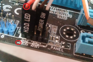
На этой картинке отображены разъёмы материнской платы для подключения коннекторов.
В основном (бывают исключения) под разъёмами мелким шрифтом написаны порядок подключения коннекторов и полярность. В моём случае указано:
PWR_LED (три разъемчика) — индикация включенного компьютера;
+PW- (PWRSW) — кнопка включения питания ПК;
-RES+ (RESET) — кнопка для перезагрузки ПК;
+HD- (IDE_LED, HDD_LED) — светодиод обращения к жесткому диску;
+SPEAK- (SPEAKER) — тот самый сигнал(ы), который издаёт компьютер при включении, если обнаружена ошибка.
Коннекторы выглядят так (см. скрины)

К каждому коннектрору подходят два провода:
POWER LED (зеленый, белый);
H.D.D. LED (желтый, белый);
POWER SW (черный, белый);
RESET SW (оранжевый, белый);
SPEAKER (черный, красный).
В данном случае белые это минус «-» или Ground (земля) , а цветные «+». У коннектора SPEAKER (черный, красный) — чёрный «+», а красный «-«. Чтобы определить полярность коннекторов, достаточно его перевернуть на тыльную сторону — видим на против одного проводка маленький чёрный треугольник — это «+».
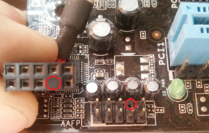
Переходим к следующему этапу, подключение передних дополнительных USB — разъёмов и картридера в разъёмы F_USB2 и F_USB1 (разницы нет, но лучше начинать по порядку). Если уже коннектор «спаянный», т.е. все проводки собраны в одну колодку — процесс значительно упрощается.
Просто подключаем этот «большой» коннектор состоящий из: восьми проводков, одного пустого и одного запаянного разъёма (всего десять) таким образом, чтобы ПУСТОЙ разъемчик совпал с ЗАПАЯННЫМ гнездом в коннекторе. (см. скрины)

А, вот если у Вас пучок проводов как на картинке — нарисую наглядную схемку:)

Здесь мы видим: POWER (Питание — 2 шт.), GND (Ground — «земля» 2шт.), D3+ (плюс), D3- (минус) на один порт usb и D2+ (плюс), D2- (минус) на другой порт. Как Вы уже догадались, два коннектора POWER идентичны и их можно менять местами между собой, так же как и GND. Главное не перепутать местами POWER и GND.

Так теперь осталось разобраться с подключением F_AUDIO разъемов для микрофона и наушников.
Опять же, если Вам повезло и от передней панели идёт большая колодка с 10-ью гнездами, просто вставляем (тут точно не ошибетесь). У меня случай поинтереснее. ) А, именно такие коннекторы: SPK R (выход правого канала на переднюю панель), SPK L (выход левого канала на переднюю панель), MIC (выход микрофона на переднюю панель) и GND.


Вот и всё подключено. Спасибо за внимание, удачи.
Если у Вас отличаются провода, названия коннекторов (колодок) и тд. и тп. не ленитесь, скачайте с официального сайта производителя Вашей материнской платы мануал (руководство) и там 99% найдёте схемы подключения всех F_PANEL, F_AUDIO и F_USB.
Черный экран windows 7 — Узнайте как избавиться от черного экрана Windows 7.
Восстановление windows 7 — Как произвести восстановление системы Windows 7.
Как активировать windows 7 — Как легально активировать windows 7.