-
Contents
-
Table of Contents
-
Bookmarks
Quick Links
ASM 340
Leak detector
Operating Instructions
EN
Summary of Contents for Pfeiffer ASM 340
-
Page 1
ASM 340 Leak detector Operating Instructions… -
Page 2: Table Of Contents
Table of contents Table of contents About this manual ……….4 1.1 Validity.
-
Page 3
Table of contents 7.1.4 Erasing ……….30 7.1.5 Viewing a recording. -
Page 4: About This Manual
About this manual Validity This operating manual is for customers of Pfeiffer Vacuum. It describes the functioning of the designated product and provides the most important information for safe use of the unit. The description follows applicable EU guidelines. All information provided in this operating manual refers to the current state of the product’s development.
-
Page 5: Conventions
About this manual Conventions 1.2.1 Safety instructions Operating manual safety instructions Pfeiffer Vacuum are based on the UL, CSA, ANSI Z-535, SEMI S2, ISO 3864 and DIN 4844 certification standards. This document de- scribes the following information and danger levels: DANGER Imminent danger Indicates an imminent hazardous situation that will result in death or serious injury.
-
Page 6: Pictographs
About this manual 1.2.2 Pictographs Prohibition of an action or activity in connection with a source of danger, the disregarding of which may result in serious accidents Warning of a displayed source of danger in connection with operation of the unit or equipment Command to perform an action or task associated with a source of dan- ger, the disregarding of which may result in serious accidents 1.2.3…
-
Page 7
About this manual Quality: certifies that the product has been certi- fied compliant with quality control upon leaving the factory. Indicates whether the Bluetooth, Wi-Fi or Ether- HLD1302577 — RS232 net options have been installed on the products, Bluethooth MAC address and their MAC addresses. -
Page 8: Safety
Safety Safety Safety precautions Obligation to inform Any person responsible for installing, using or maintaining the product must first read the security instructions in this operating manual and comply with them. It is the operating customer’s responsibility to protect all operators against the dan- gers associated with the product, with the media pumped and with the entire instal- lation.
-
Page 9: Protective Equipment
Safety NOTICE Wet Model: Filling with oil Oil must be added to the primary pump before the detector is switched on. The potential hazards for a leak detector involve electricity, the tracer gas, the pres- surised nitrogen supply and the lubricant (for the Wet models). ●…
-
Page 10: Proper Use
Safety Proper use NOTICE EC conformity The manufacturer’s declaration of conformity becomes invalid if the operator modifies the original product or installs additional components. Following installation into a plant and before commissioning, the operator must check the entire system for compliance with the valid EU directives and reassess it accor- dingly.
-
Page 11: Transport And Storage
Transport and storage Transport and storage Upon delivery, check that the product has not been damaged during transport. If the product is damaged, contact the carrier and notify the manufacturer. In all situations we recommend: keeping the product in its original packaging so it stays as clean as it was when dis- patched by us.
-
Page 12: Storage
Transport and storage Before moving a detector, make sure that the covers are properly attached: the front cover cancels 3 fixing screws for the rear cover (out of the 5 screws in total): make sure that these 3 screws are in place and properly tightened. …
-
Page 13: Product Description
● 1 protective cover 4.1.2 Variants The ASM 340 leak detectors are particularly suitable in Industry for vacuum and sniffing leak detection, in various applications from maintenance to small production applica- tions. Easy operation, robustness, ultra fast response time, are among the outstanding features of these compact multipurpose units.
-
Page 14: Connection Interface
Test method The test method is chosen depending on the part to be tested. For more information about leak detection test methods, see Leak detector compendi- um on the website www.pfeiffer-vacuum.com. 4.3.1 Hard vacuum test ● Part that can be connected to pipe and placed under a vacuum ●…
-
Page 15: Sniffing Test
Product description At the time of spraying, the leak rate does not appear instantly. There is a response time which depends on the volume V to be tested and on the tracer gas pumping speed S of the system at part’s inlet, according to the ratio: T = V/S (T in seconds, V in litres, S in l/s).
-
Page 16: Installation
Installation Installation Prerequisites for optimising measurement To optimise pumping and measurement speed: ● Use pipe with a diameter equal to the diameter of the detector’s inlet. The pipes should be as short as possible and completely sealed. ● Do not use plastic hoses such as compressed air pipes. ●…
-
Page 17: Filling With Oil (Wet Model Only)
Installation 5.3.1 Storing the lifting handles One the detector has been installed, the handles can be removed and stored in the back of the detector or used to place the control panel on a work surface. ● 5-mm Allen key. Tools required Fig.
-
Page 18: Connecting The Purge Circuit
Installation Make sure that the detector is off (circuit breaker at 0, the control panel screen is off) and in a horizontal position. Open the cover. Remove the oil fill cap (1) from the rotary vane pump (2). …
-
Page 19: Connection To The Mains Power Supply
Installation Connection to the mains power supply WARNING Risk of electromagnetic disturbance The product’s EMC rating is obtained on the understanding that it is installed in compli- ance with EMC rules. Use sheathed links and connections for interfaces in environments that produce dis- turbance.
-
Page 20: Connecting The Part/Installation To Be Tested
Installation Connecting the part/installation to be tested NOTICE Limit of operation Make sure that the parts or chambers connected to the inlet of our products withstand a negative pressure of 1 · 10 hPa in relation to atmospheric pressure. ●…
-
Page 21: Operation
Operation Operation Control panel It is interfaced with the detector and is used to: – display information about the test – access the available functions – setting of the detector’s parameters. For a screenshot, set a function key to [Screen Copy] (see 7.7.2). 6.1.1 Description START…
-
Page 22: Contrast — Brightness — Screen Saver
Operation Keys for setting the values Moving to the next function/screen/parameter Return to the previous display Return to the previous display and confirm the changes made Return to the previous display without confirming the changes made Deleting the selected file Set point setting 1 Exponent setting 2 Mantissa unit setting…
-
Page 23: Standard» Screen
Operation Fig. 6: Example of each screen 1 «Standard» screen (home) Information about the current test 2 «Graph» screen Monitoring and recording the leak rate and/or the inlet pressure 3 «Vacuum circuit» screen Vacuum circuit of the detector and the status of the valves 4 «Settings»…
-
Page 24: Settings» Screen
Operation Mute function indicator Air inlet function indicator Cell pressure bargraph display Leak detector unit Leak rate correction function indicator 10 Zero function indicator 11 Detector inlet pressure display (unit consistent with the leak rate unit) 12 Tracer gas ( He or H A password can be used to lock access to the «Settings»…
-
Page 25: Prerequisites To Use
Operation 6.1.7 «Vacuum circuit» screen Vacuum circuit of the detector and the status of the valves. The vacuum circuit varies depending on the status of the valves, but does not make it possible to manage the valves. Fig. 7: Example of a vacuum circuit Red valve Valve closed Green valve…
-
Page 26: Switching The Detector On
Operation NOTICE Risk of seizing Never move the detector while it is in use, even if it is placed on a trolley. Before each switching on: All models Become familiar with the safety instructions (see 2). Remove the cover before using the product. …
-
Page 27: Monitoring Operation
Operation The test can also be started using a remote control (accessory): see Remote con- trol Operating instructions. Select the ’sniffing’ test method (see 7.4.1). Sniffing test With the leak detector in Stand-by mode, connect the sniffing probe (accessory) to the provided connector ( ) and select Standard or Smart probe model (see 7.4.4).
-
Page 28: Advanced Settings
Advanced settings Advanced settings «Graph» screen Access the «Graph» screen by pressing 7.1.1 Description Monitoring and recording the leak rate and/or the inlet pressure. Fig. 10: «Graph» screen 1 Deleting/Viewing/Recording a plot 2 Plot of the tracer gas leak rate (in red) 3 Scale of the tracer gas leak rate (in red) 4 Time scale 5 Inlet pressure scale (in blue)
-
Page 29: Recording
Advanced settings Example: leak rate = 5·10 Pa·m /s (5·10 mbar·l/s) ● automatic scale 2 decades: scale from 1·10 to 1·10 Pa·m (1·10 to 1·10 mbar·l/s) ● automatic scale 4 decades: scale from 1·10 to 1·10 Pa·m (1·10 to 1·10 mbar·l/s) …
-
Page 30: Erasing
Advanced settings 7.1.4 Erasing Display the «Graph» screen (Fig. 10) (see 7.1.1). Current window Press [Clear] (ref. 1) and validate the message. Clearing the current window does not delete the current recording or recordings already made. Display the «Graph» screen (Fig. 10). Recording …
-
Page 31
Advanced settings Set the area to be reduced (ref. 1 then ref. 2 Fig. 14): return to the original graph. Fig. 14: Return to the original graph Exact measurement of a point only available on a recording. Measurement Fig. 15: Example of the recording of a point 1 Modifying the leak rate and inlet pressure scales 2 Point selected … -
Page 32: Saving A Recording
Advanced settings 7.1.6 Saving a recording This function is used to save the most recent recording on a SD card to be played back/ analysed later on a PC. Saving is not automatic. It is possible to save a screenshot of the recording (.bmp) or to generate a file (.txt) with all the measurements taken.
-
Page 33
Advanced settings SET POINTS Selection Choice — Setting Initial settings limit Audio Status Invalid / Valid Valid Setting (If valid) 1 — 9 Digital voice Status Invalid / Valid Valid Setting (If valid) 1 — 9 Pollution Status Invalid / Valid Invalid Setting (If valid) 1·10… -
Page 34
Advanced settings SPECTRO Selection Choice — setting Initial settings limit Tracer Gas Helium 4 / Helium 4 Helium 3 / Hydrogen Filament selected 1 / 2 Filament Off / On Filament Status 0 — 100 % 100 % Calibrated Leak Tracer Gas Helium 4 / Helium 4… -
Page 35
Advanced settings MAINTENANCE Selection Choice — Setting Initial settings limit Pump Information Primary Pump 1 If Dry Model Used Status Speed Maxi Synchro If Wet Model Parameters not avail- able Secondary Pump 1 Status Rotation Synchro Speed (rpm) 90000 TMP information Access to Pump gen- eral information Events History… -
Page 36
Advanced settings CONFIGURATION Selection Choice — Setting Initial settings limit Screen settings Brightness High / Low High Contrast 0 — 100 Panel Off None / None 15 min / 30 min / 1 h / 2 h / Paging Function Without RC 500 WL remote control detected — None With RC 500 WL remote control detected… -
Page 37
Advanced settings ADVANCED Selection Choice — Initial settings Setting limit Leal Detection Internal Pirani Cali- Function launching bration External Gauge Gauge None / None TPR / PCR / Linear External Pressure (mbar) Pression Inlet Source Internal / External Internal Full scale (mbar) (if Linear) 0.1 — 50000 To set Purge Valve… -
Page 38
Advanced settings ADVANCED Selection Choice — Initial settings Setting limit Input/Output Serial link 2 Type Not used / (I/O 37 pins) USB / Bluetooth / Network Parameters Mode Basic / Advanced Spreadsheet / Advanced / Export. Data / PV Protocol Handshake None / None… -
Page 39: Set Points Menu
Advanced settings ADVANCED Selection Choice — Initial settings Setting limit Input/Output (I/O 37 I/O connector Digital Transis- 9 — 28 Allocation See Manual I/O 37 Bypass pins) tor Output pins Activation NO / NC 8 — 27 Allocation See Manual I/O 37 Detector Ready pins Activation NO / NC…
-
Page 40: Audio Alarm And Digital Voice
Advanced settings 7.3.1 Audio alarm and digital voice The audio alarm informs the operator that the reject set point has been crossed. The lev- Audio alarm el varies from 0 to 8 (0 to 90 dB (A)). From the «Settings» screen, press [Set points]. Audio …
-
Page 41: Sniffing Reject Set Point
Advanced settings For quick access from the control panel, set a function key for [Reject Point]: (see 7.7.2) Fig. 19: «Reject point» screen using a function key. 7.3.4 Sniffing reject set point The sniffing reject set point defines the acceptance set point for parts that are «accepted/ rejected»…
-
Page 42: Test Methods
Advanced settings 7.4.1 Test methods There are 2 possible test methods (see 4.3): ● hard vacuum test, ● sniffing test. From the «Settings» screen, press [Test]. Method Select the test method. – For the hard vacuum test, set the test mode: (see 7.4.3) –…
-
Page 43: Test Mode
Advanced settings % He in the gas used 100 % 50 % Leak rate displayed on 1·10 Pa·m 5·10 Pa·m 5·10 Pa·m 1·10 Pa·m the leak detector without 1·10 mbar·l/s 5·10 mbar·l/s 5·10 mbar·l/s 1·10 mbar·l/s COR value Leak rate displayed on 1·10 Pa·m the leak detector with…
-
Page 44: Inlet Vent
Advanced settings 7.4.6 Inlet vent This function allows an inlet vent after a hard vacuum test stop. It allows the detector’s inlet, and therefore the connected part or installation, to return to atmospheric pressure. This function is secure: a confirmation message «Inlet vent? Please confirm.» appears each time the operator requests an inlet vent.
-
Page 45: Zero Activation
Advanced settings From the «Settings» screen, press [Test] [Memo Function]. Display time Setting required if the function is active. Activate the display time delay. • On = the value of the measured leak rate flashes for the set duration. •…
-
Page 46: 7.4.10 Regeneration
Advanced settings ● Digital Transistor Output 9 – 28 = Bypass If set otherwise, set like this: see 37 pin I/O board Operating instructions. Press [Test] [Bypass Option]. Mode None = External Bypass pump installed but not active Quick pump = External Bypass pump active only during roughing Partial flow = External Bypass pump active during roughing and test + leak rate cor- rection to be applied Evac.
-
Page 47: Spectro Menu
Advanced settings When there is a very gross leak, the detector does not switch to Gross Leak mode and remains in roughing. Function activated and pressure < 100 hPa, a message notifies the operator that the de- tector has switched automatically to massive mode: the detector can then perform a qualitative leak test (leak information >…
-
Page 48: Filament Parameters
Advanced settings 7.5.2 Filament parameters Fil. Selected Indicates the filament used for the measurement (2 filaments in the analyzer cell). Filament Indicates if the filament used is ’on’ or ’off’ when the detector is switched on. Fil. status Indicator of analyzer cell performance. Initial settings: between 90 % and 100 % Normal operation: between 10 % and 100 % Normal wear on some cell components will reduce this value over time but will not re-…
-
Page 49: Timers
Advanced settings 7.6.2 Timers From the «Settings» screen, press [Maintenance] [Timers]. Detector Number of hours that the detector is switched on. Filament 1 Number of hours that filament 1 is on. Press [xxx h] [Counter reset] to reset the counter. Filament 2 Number of hours that filament 2 is on.
-
Page 50: Pump Information
Advanced settings 6 Detector firmware information For quick access from the control panel, set a function key for [Infor.]: (see 7.7.2). 7.6.4 Pump Information No pump information for the Wet Model: the message «No parameter available» is dis- Primary Pump #1 played.
-
Page 51: Calibration History
Advanced settings RS 232 Event Description Code I303 TMP1 ctr reset Secondary pump 1 hour counter reset I304 TMP2 ctr reset Secondary pump 2 hour counter reset I305 TMP3 ctr reset Secondary pump 3 hour counter reset I306 Fil 1 ctr reset Filament 1 hour counter reset I307 Fil 2 ctr reset…
-
Page 52: Maintenance For The Analyzer Cell And The Secondary Pump
Advanced settings 7.6.8 Maintenance for the analyzer cell and the secondary pump To carry out maintenance on the secondary pump or the analyzer cell, the vacuum part of the detector must be at atmospheric pressure. This function is used to shut down the secondary pump and to perform an inlet vent so that the secondary pump and the ana- lyzer cell are at atmospheric pressure.
-
Page 53
Advanced settings START STAND-BY Fig. 28: Function keys From the «Settings» screen, press [Config.] [Function Keys]. Allocating function keys Thanks to the function keys, it is possible to give the operator access to a limited number of functions and to use a password to lock unauthorised functions on the «Settings»… -
Page 54: Application Screens
Advanced settings Validate the settings (ref. 3): the function key (ref. 2) is now allocated to the [Correc- tion] function. Fig. 32: Result of the allocation 7.7.3 Application screens From the «Settings» screen, press [Config.][Application Windows]. By pressing repeatedly on the key , the various screens available appear (see 6.1.3).
-
Page 55: Screen Settings
Advanced settings Fig. 34: The «Graph» screen is no longer available When a screen is selected again, it automatically moves to last place. Fig. 35: The «Graph» screen is available again, and in last place. Setting the «Standard» screen From the «Settings» screen, press [Config.] [Application Windows] [Std Window Parame- ters].
-
Page 56: Access — Password
Advanced settings 7.7.5 Access — Password From the «Settings» screen, press [Config.] [Access/Password]. Enter the password (’5555’ by default) and validate. The operator can lock access to one or more menus on the «Settings» screen. To access Menu access a locked menu, the operator will be asked to provide the password.
-
Page 57
Advanced settings Fig. 38: Displays with Restricted access With Medium or Restricted access, the operator can temporarily access the 6 me- nus on the «Settings» screen to set parameters. Press until the «Settings» screen is displayed with all the locked menus. … -
Page 58: Advanced Menu
Advanced settings Limits with Full access. ● No limit. Fig. 40: Displays with Full access Operator with Restricted or Medium access changing the access level. Press until the «Settings» screen is displayed with all the locked menus. Press [Config.]. …
-
Page 59: Leak Detection Menu
Advanced settings 7.8.1 Leak Detection Menu From the «Settings» screen, press [Advanced][Leak Detection]. 7.8.2 Leak Detection: Start-up timer The start-up timer prevents the leak detector from being used for a pre-determined du- ration after it has been switched on. This means measurements cannot be made until the leak detector is thermically stabilized, or while traces of tracer gas remain in the detector.
-
Page 60
Advanced settings Calibration makes it possible to verify that the detector is properly adjusted to detect the selected tracer gas and display the correct leak rate value. From the «Settings» screen, press [Advanced] [Leak Detection] [Calibration]. Calibration Select the type of calibration. See details below. Calib. -
Page 61: Leak Detection: Analyzer Cell
Advanced settings 7.8.6 Leak detection: Analyzer cell From the «Settings» screen, press [Advanced] [Leak Detection] [Analyzer Cell]. Fil. Selected Indicates the filament used for the measurement (2 filaments in the analyzer cell). Filament Indicates if the filament used is ’on’ or ’off’ when the detector is switched on. –…
-
Page 62: Leak Detection: External Gauge
Advanced settings 7.8.8 Leak Detection: External gauge Allows the leak detector to be managed by an external gauge. An external gauge can be used to manage valves, for example, depending on the measured pressure. From the «Settings» screen, press [Advanced] [Leak Detection] [External Gauge]. Gauge …
-
Page 63: 7.8.12 Input/Output: I/O Connector
Use of a wireless remote control (model RC 500 WL). PV Protocol Protocol for compatibility with the HLTxxx detector protocol. List of orders for the protocol compatible with ASM 340. See the RS 232 operating instructions). Ext. Module Full control of the detector by a supervisor.
-
Page 64: 7.8.13 Sd Card Menu
Advanced settings 7.8.13 SD Card menu From the «Settings» screen, press [Advanced] [SD card]. Load Detector Load the saved parameters onto the SD card. Param. Save Detector Save the leak detector parameters to the SD card. Param. View * BMP View the saved «.bmp»…
-
Page 65: Maintenance / Replacement
Maintenance / replacement Maintenance / replacement NOTICE Disclaimer of liability Pfeiffer Vacuum accepts no liability for personal injury or material damage, losses or operating malfunctions due to improperly performed maintenance. The liability and war- ranty entitlement expires. Maintenance intervals and responsibilities The detector maintenance operations are described in the Maintenance instructions for the detector.
-
Page 66: Service
Overhaul and repair in the Pfeiffer Vacuum Service Center The following general recommendations will ensure a fast, smooth servicing process: Fill out the «Service Request/Product Return» form and send it to your local Pfeiffer Vacuum Service contact. Include the confirmation on the service request from Pfeiffer Vacuum with your ship- ment.
-
Page 67: 10 Accessories
/s + Japon) 106690 RC 500 WL remote control PT 445 432 -T Standard Sniffer Probe see Pfeiffer Vacuum catalog Sniffer probe extension (10 m) 090216 Smart Sniffer Probe (3 m) BG 449 207 -T Smart Sniffer Probe (5 m)
-
Page 68: 11 Technical Data And Dimensions
Technical data and dimensions 11 Technical data and dimensions 11.1 General Databases of the leak detectors’ technical characteristics Pfeiffer Vacuum: ● Technical characteristics according to: – AVS 2.3: Procedure for calibrating gas analyzers of the mass spectrometer type. – EN 1518: Non-destructive testing. Leak testing. Characterization of mass spec- trometer leak detectors.
-
Page 69: 11.4 Dimensions
Technical data and dimensions Conversion table: gas throughput units mbar l/s Pa m sccm Torr l/s atm cm mbar l/s 59.2 0.75 0.987 Pa m 9.87 sccm 1.69 · 10 1.69 · 10 1.27 · 10 1.67 · 10 Torr l/s 1.33 1.33 78.9…
-
Page 70: Declaration Of Conformity
The technical file is drawn up by Mr Gilles Baret, adixen Vacuum Products, Société par Actions Simplifiées [simplified joint stock company], 98, avenue de Brogny·B.P. 2069, 74009 Annecy cédex, France. ASM 340 Harmonised standards and national standards and specifications which have been ap- plied:…
-
Page 71
Vacuum solutions Pfeiffer Vacuum stands for innovative and custom from a single source vacuum solutions worldwide, technological perfection, competent advice and reliable service. Complete range From a single component to complex systems: of products We are the only supplier of vacuum technology that provides a complete product portfolio.
-
Contents
-
Table of Contents
-
Troubleshooting
-
Bookmarks
Quick Links
ASM 340
Leak detector
Maintenance instructions
EN
Related Manuals for Pfeiffer Vacuum ASM 340
Summary of Contents for Pfeiffer Vacuum ASM 340
-
Page 1
ASM 340 Leak detector Maintenance instructions… -
Page 2: Table Of Contents
Table of contents Table of contents About this manual ……….4 1.1 Validity.
-
Page 3
Table of contents 5.6.2 Access to the fluid reservoir ……28 5.6.3 Replacing the operating fluid reservoir . -
Page 4: About This Manual
About this manual Validity This maintenance manual is intended for the customers of the Pfeiffer Vacuum Compa- ny. It describes the product maintenance operations which can be performed by the user on the product concerned. This documentation must be used with the operating manual of the product of the same name.
-
Page 5: Conventions
About this manual Conventions 1.2.1 Safety instructions Operating manual safety instructions Pfeiffer Vacuum are based on the UL, CSA, ANSI Z-535, SEMI S2, ISO 3864 and DIN 4844 certification standards. This document de- scribes the following information and danger levels: DANGER Imminent danger Indicates an imminent hazardous situation that will result in death or serious injury.
-
Page 6: Pictographs
About this manual 1.2.2 Pictographs Prohibition of an action or activity in connection with a source of danger, the disregarding of which may result in serious accidents Warning of a displayed source of danger in connection with operation of the unit or equipment Command to perform an action or task associated with a source of dan- ger, the disregarding of which may result in serious accidents Important information about the product or this document…
-
Page 7: Safety And Maintenance Information
● Do not switch on the product if the covers are not in place. ● To return the product to one of our Pfeiffer Vacuum service centers, read the after- sales Service procedure and complete the declaration of contamination available on our website.
-
Page 8: Protective Equipment
Safety and maintenance information Protective equipment In some situations, personal protective equipment must be worn when handling the de- tector and its components. Customers must provide operators with the necessary equip- ment. This equipment must be checked regularly and used in accordance with the sup- plier’s recommendations.
-
Page 9: Tools And Spare Parts
Use only spare parts available by asking Pfeiffer Vacuum Service. Ordering information is available in chapter Spare parts. To correctly identify the product when communicating with Pfeiffer Vacuum, always have the information from the product rating plate available.
-
Page 10: Maintenance Intervals And Responsibilities
(2) Routine maintenance: accord- (3) Level : (4) Site: (with significant flow or contami- ing to usage conditions I = Operator OS = On site nation) II = Technical or trained operator WS = In Pfeiffer Vacuum service III = Service center center.
-
Page 11: Maintenance Time Monitoring
Maintenance intervals and responsibilities Maintenance time monitoring The cycle counters of the primary pump and turbomolecular pump alert the operator that a maintenance operation must be performed (see Maintenance Menu of the Operating Instructions).
-
Page 12: Calibration
Calibration Calibration Purpose Calibration helps ensure that the leak detector is correctly adjusted to detect the tracer gas selected and display the correct leak rate. A calibrated leak is used to calibrate the leak detector. Depending on the test method, different types of calibration can be performed. Test method Hard Vacuum Sniffing…
-
Page 13: Calibration With An External Calibrated Leak
Calibration Calibration with an external calibrated leak 4.3.1 External calibrated leak The operator must use a calibrated leak containing the tracer gas selected ( He or ). There are several types of external calibrated leaks, with or without reservoir, with or without valve, covering several leak ranges.
-
Page 14: Calibration On Concentration (Sniffing Test Mode Only)
Calibration – calibration with a leak of 2·10 mbar·l/s – the displayed leak rate is: 2·10 + 5·10 = 2.5·10 mbar·l/s 4.3.3 Calibration procedure with external leak in Hard Vacuum test Allocate a function key to [Auto.Cal] (see Configuration Menu in the Operating In- structions).
-
Page 15: Calibration Of A Leak Detector Connected To A Pumping Unit
Calibration ● type of calibrated leak = concentration (see Spectro Menu) ● calibration = operator (see Advanced Menu) ● tracer gas = He (see Spectro Menu) Connect the sniffer probe to the detector. Verify that the detector is in Stand-by mode. …
-
Page 16
Calibration – Press [Return] to exit the function. Press [Reset] to reset the correction factor to 1. The ’COR’ indicator light (see Standard screen of the Operating Instructions, ref. 9) is illuminated on the control panel as soon as the value of the correction factor is not 1. The digital display takes into account the correction factor applied. -
Page 17: Maintenance / Replacement
Maintenance / replacement Maintenance / replacement Cleaning the covers Clean the covers using a lint-free cloth and a product which does not damage printed surfaces and self-adhesive labels. Dismantling the covers Tools ● 5 mm Allen key supplied in the maintenance kit 5.2.1 Dismantling the front cover …
-
Page 18: Maintenance Of The Internal Calibrated Leak
Maintenance / replacement 5.2.2 Dismantling the rear cover Dismantle the front cover. Loosen and remove the 5 fixing screws (1), (2) and their washers. Disconnect the harness (3) and the ground point (4). Remove the rear cover. When reassembling the cover, make sure that the 5 fixing screws for the rear cover on the frame are in place and properly screwed.
-
Page 19: Analyzer Cell Maintenance
However, to guarantee the reliability of the test, we recommend that you regularly reca- librate (3 years maximum) every leak with reservoir to check its leak rate: this applies to both internal and external calibrated leaks. Return the leak to your Pfeiffer Vacuum service center for recalibration purposes. 5.3.3 Setting …
-
Page 20: Dismantling
Maintenance / replacement 5.4.1 Dismantling ● Torx screwdriver supplied in the maintenance kit Tools Procedure WARNING Risk of burning associated with hot surfaces When in operation, certain mechanical parts can reach high temperatures. If the detec- tor was used recently: …
-
Page 21: Filament Replacement
Maintenance / replacement 5.4.3 Filament replacement ● Torx screwdriver supplied in the maintenance kit Tools ● Flat pliers ● Filament (see 9) Filament is consumables. As such, it is not covered by the warranty. Procedure The oxidation of the iridium filament is normal: do not touch the filament with your fingers.
-
Page 22: Primary Pump Maintenance (On Wet Model)
Maintenance / replacement Take a fastening clip (5) with the flat pliers: this clip will ensure electrical contact be- tween the filament and the cell (A Fig. 10). Fit the clip on the connector (6) and on the strip of the filament (8) (B Fig. 10). …
-
Page 23: Oil Quality Inspection
Maintenance / replacement Fig. 12: Oil level check 5.5.3 Oil quality inspection For the pump to function in optimal conditions, oil quality must be checked regularly. Thickening and darkening of the oil, combined with a burning smell, are signs of lubricant deterioration.
-
Page 24: Flushing The Pump
Maintenance / replacement Connect the drain connector (5). Fig. 13: Fitting of the drain connector Recover waste oil. When all the oil has been drained, remove the drain connector. Fill with fresh oil (see 5.5.6). 5.5.5 Flushing the pump NOTICE Only use approved operating fluids…
-
Page 25: Filling The Pump
Maintenance / replacement 5.5.6 Filling the pump NOTICE Only use approved operating fluids The pumps are factory tested using adixen oil. The same oil must be used during operation. The oil safety data sheet is available on the website. DANGER Health risk in case of oil contact The pumps are delivered empty of oil: the oil is delivered in separate containers.
-
Page 26: Replacement Of The Internal Oil Mist Eliminator
Maintenance / replacement Fig. 16: Dismantling the primary pump Loosen the screw (+ washer) of the mist eliminator’s mounting bracket (3), then re- move the mist eliminator. Loosen the 4 fixing screws (+ washers) of the pump underneath the detector frame. When dismantling the primary pump to send it to the service center, keep the tightening clamp, power cable and entire mist eliminator unit (mist eliminator + bracket + screws).
-
Page 27: Installation Of An External Mist Eliminator
Maintenance / replacement 5.5.9 Installation of an external mist eliminator The operator can use an external oil mist eliminator to replace the internal oil mist elim- inator installed on the detector: this modification requires connecting an accessory: an exhaust connector for the pump. ●…
-
Page 28: Maintenance Of The Turbomolecular Pump
Maintenance / replacement Maintenance of the turbomolecular pump WARNING Risk of burning associated with hot surfaces When in operation, certain mechanical parts can reach high temperatures. If the detec- tor was used recently: Let it cool down for at least 10 minutes before working on the turbomolecular pump. …
-
Page 29: Replacing The Operating Fluid Reservoir
Maintenance / replacement 5.6.3 Replacing the operating fluid reservoir WARNING Risk of intoxication in case of contact with substances hazardous to health. Always take appropriate precautions when handling the operating fluid reservoir: Dispose of operating fluid reservoirs in accordance with the applicable legislation. Safety data sheet available upon request or at www.pfeiffer-vacuum.com …
-
Page 30: Pirani Gauge Maintenance
Maintenance / replacement Using tweezers, pull out Porex rods (8 pieces). Remove impurities from the turbopump and the end cover with a clean, lint-free cloth. Do not use any cleaning fluids! Using tweezers, insert new Porex rods (8 pieces). …
-
Page 31: Fan Maintenance
Maintenance / replacement Fan maintenance 5.8.1 Location Fig. 23: Fan location Air inlet fan Turbomolecular pump fan Air Exhaust fan ● Philips screwdriver Tools/ Spare parts ● Fan + grill (see 9) 5.8.2 Replacement of the air inlet fan Remove the front and rear cover of the detector (see 5.2). …
-
Page 32: Replacement Of The Turbomolecular Pump Fan
Maintenance / replacement Fig. 25: Placing of fan and harness 5.8.3 Replacement of the turbomolecular pump fan Remove the front cover of the detector (see 5.2.1). Disconnect the fan harness (1) of fan (V2) from the 24V distribution board (2). …
-
Page 33: Air Filters Maintenance
Maintenance / replacement Fig. 27: Maintenance of the exhaust fan Air filters maintenance 5.9.1 Air filters location Fig. 28: Air filters location Air filter no. 1 Air filter no. 2 Air filter of the vacuum block ● 13 mm and 17 mm spanners (for the air filter of the vacuum block) Tools/Spare parts ●…
-
Page 34: Replacement Of The Vacuum Block Air Filter
Maintenance / replacement 5.9.3 Replacement of the vacuum block air filter 2 + 3 = 4 Fig. 30: Maintenance of the vacuum block air filter Remove the front cover (see 5.2.1). Loosen the filter connector (2) with the 13 mm spanner to free the tube (1). …
-
Page 35: Shutdown
The manufacturer’s obligation to recover this equipment applies only to complete items of equipment which have not been modified or retrofitted, using only spare parts from adixen Vacuum Products, sold by Pfeiffer Vacuum and including all their assemblies and sub-assemblies.
-
Page 36: Malfunction
Malfunction Malfunction What happens in case of a fault The leak detector can display warnings or faults on screen at any time. Fig. 31: Standard screen with warning [i Next] 7.1.1 Warning / fault display Press the key to display the fault. Level 1: Warning Press the [i Next] key to display the maintenance information Level 2: Major fault: erroneous measurement…
-
Page 37: Troubleshooting Guide
Malfunction 7.1.3 List of warnings / faults Level RS Order RS 232 Code Information calib. test mode lost Dynamic Calib. Fail w145 maintenance required w150 primary pump maint w160 high. vac pump maint w180 new fil#2 required w181 new fil#1 required w211 manual calibration w220…
-
Page 38: Installation Of The Application
Malfunction 7.2.1 Installation of the application Insert the Operating Manual CDRom into the CD/DVD player of the computer. Launch the «ASM340» application. Select the language. Select the interactive application ’Troubleshooting’. Install the application on your computer. Fig.
-
Page 39
Malfunction… -
Page 40: Service
Fill out the «Service Request/Product Return» form and send it to your local Pfeiffer Vacuum Service contact. Include the confirmation on the service request from Pfeiffer Vacuum with your ship- ment. Fill out the declaration of contamination and include it in the shipment (mandatory!).
-
Page 41: Spare Parts
See following pages Tool F100 Monitoring and Display F200 Power and electrical supply F300 Automatic control system and electronic circuits F400 Measurement F500 Pumping F600 Vacuum block F700 Pipes — Connections — Seals F800 Cover F900 ASM 340 specific accessories F1000…
-
Page 42
F 100 Tools ASM 340 Description Qty Remarks A006 DN16KF Calibrated Leak Adaptator Kit 110715 A007 DN25KF Calibrated Leak Adaptator Kit 110716 A013 Tee, Reducing — DN25/25/16KF 068269 A016 Calib. Leak With Valve 1-3.10-6 DN25KF FV4610 A020 Clamp DN20/25KF 083264… -
Page 43
F 200 Monitoring and display ASM 340 Description Qty Remarks B036 Control Panel (Black) — 340 121557S Spare parts DB 2013/06… -
Page 44
F 300 Power and electrical supply ASM 340 Description Qty Remarks C002 Cable, Main Power; 2 m — Italy 104758 C003 Cable, Main Power; 2 m — Switzerland 103718 C004 Cable, Main Power; 2 m — UK 104411 C005 Cable, Main Power; 2 m — USA… -
Page 45
F 400 Automatic control system and electronic circuits ASM 340 Description Qty Remarks D026 Loudspeaker; 90 DB/D 10 cm 060097 D073 P0482E1 Bluetooth Board P0482E1 Spare parts DB 2013/06… -
Page 46
F 500 Measurement ASM 340 Description Qty Remarks E025 Gauge, PI1 (Aluminium) 795706 E026 Filament for PI1 Gauge 057972 E047 Filament for 3G Analyzer Cell 114864S E068 3G.2 Cell ExtrACTion Electrode — Service 119641 E084 Calibrated Leak, Internal — 340… -
Page 47
F 600 Pumping ASM 340 Description Qty Remarks F014 Oil, A200 (1L) 068694 F015 Funnel 067592 F126 Oil mist Eliminator 21 m3/h D30 mm — 340 121494 F132 Oil reservoir for Splitflow 50 — 340 PM 143 740 –T F133… -
Page 48
F 700 Vacuum block ASM 340 Description Qty Remarks G071 Inlet port filter — 340 103395 G074 Vacuum block filter — 340 122237 Spare parts DB 2013/06… -
Page 49
F 800 Pipes — Connections — Seals ASM 340 Description Qty Remarks H165 O’Ring 3.6 x 29.3 FPM 082025 H166 Vacuum block filter — 340 122237 H170 Draining connector — 340 Wet 107646 Spare parts DB 2013/06… -
Page 50
F 900 Cover ASM 340 Description Qty Remarks I114 Protection cover — 340 A006733 I115 Lifting handle — 340 A333918 I116 DN25KF Inlet Pipe Frame — 340 A334286 Spare parts DB 2013/06… -
Page 51
F 1000 Options and accessories ASM 340 Description Qty Remarks J077 20 µm Poral Filter D 114 mm 105847 J078 5 µm Poral Filter D 114 mm 105848 J174 O’ring Ø 5 mm — D 114 mm 082152 J175 20 µm Poral Filter DN25/25 KF… -
Page 52
F 1000 Options and accessories ASM 340 Description Qty Remarks J185 RC 500 WL remote control -340 PT 445 432 -T J186 Cable transmitter/ASM340 — RC500WL A466613 J187 Cable remote/ASM340 — RC500WL A465975 J188 Bypass Kit Europe — 340 PT 445 411 -T… -
Page 53
Vacuum solutions Pfeiffer Vacuum stands for innovative and custom vacuum solutions worldwide, technological perfection, from a single source competent advice and reliable service. Complete range From a single component to complex systems: of products We are the only supplier of vacuum technology that provides a complete product portfolio.
- П
 одготовить течеискатель ASM 340 (ТИ) к работе, для чего:
 одготовить течеискатель ASM 340 (ТИ) к работе, для чего:
- проверить уровень масла в форвакуумном насосе ТИ по уровнемеру;
- соединить корпус ТИ с шиной заземления рабочего места;
- сетевым кабелем (может лежать в ящике, расположенном в верхней части корпуса ТИ) подключить ТИ к электросети напряжением 220В.
ВНИМАНИЕ! Управление сенсорным экраном осуществлять только руками без использования твердых предметов, таких как ручки, отвертки и т.п.
Перемещать, подвигать, стучать по столу на котором установлен ТИ запрещается!
- Включить переключатель питания, на левой боковой панели корпуса ТИ в положение «I». На сенсорном экране панели управления загорится подсветка. Процесс вывода на режим ожидания происходит автоматически.
При появлении на экране надписи: «Storage Delay (35 days):10 min» нажать кнопку [START/Stend-by] ![]() на панели управления.
на панели управления.
ТИ будет готов когда на сенсорном экране отобразится команда «ОЖИДАНИЕ».


- Нажать кнопку [START/Stend-by]
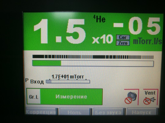
 на панели управления. ТИ автоматически проведет откачку входа, экран станет цветным и отобразится команда «ИЗМЕРЕНИЕ».


- Открыть клапан KF25 на входной линии подстыковки ТИ.
- Открыть контрольную течь (Qкт) на камере, дождаться стабилизации показаний на дисплее ТИ (≈ 7-10 мин.), в зависимости от объема камеры время стабилизации может быть увеличено.

- Несколькими нажатиями клавиши «окна»
 найти в нижней строке функцию «КОРРЕКЦИЯ»,
и нажатием кнопки войти.
- Повторным нажатием кнопки включить коррекцию.


Индикатор включения/отключения
коррекции
- Выбрать параметр «ВЕЛИЧИНА». Используя клавиши «плюс», «минус» и «множитель» установить такое значение коррекции, чтобы отображаемое на ТИ значение течи совпадало со значением указанным на контрольной течи (установленной на камере).


Путем нажатия кнопок ![]() , установить требуемое значение.
, установить требуемое значение.
Настройка уставки:

- Нажать кнопку «ДОМОЙ» , вернуться на рабочий экран.
- Закрыть Qкт, дождаться установившихся показаний (≈ 3-5 мин.), в зависимости от объема камеры время стабилизации может быть увеличено.
Индикатор включения/
отключения
«НОЛЬ»
- Кнопкой нажать вкладку «НОЛЬ» в нижнем меню управления. Если функция «ноль» отсутствует в нижней строке, то нажатием на клавишу «Окна» вывести функцию «ноль» на экран и применить её.


- Открыть Qкт, дождаться стабилизации показаний, убедиться что показания ТИ совпадают с Qкт. Если есть не значительное отклонение, кнопкой «КОРРЕКЦИЯ» подредактировать значение (см. пункт 8).
- Закрыть Qкт дождаться стабилизации фона.
- Открытием/закрытием Qкт еще раз убедиться в точности настройки ТИ.
- Установить порог отбраковки, для чего несколькими нажатиями клавиши «окна» найти в нижней строке функцию «УСТАВКА» используя клавиши «плюс», «минус» и «множитель» установить уровень отбраковки изделия.
- . Провести контроль герметичности согласно поданной заявки и Программы и методики 154.ПМ003.
— заправить ОИ пробным зазом;
— выдержать ОИ под пробным давлением установленное время;
— зафиксировать показания течеискателя отображаемые на дисплее;
— записать измеренное значение в журнал;
— удалить пробный газ из ОИ;
- По завершению работы:
ВНИМАНИЕ!!!
Оператор может перемещать или обслуживать ТИ только после его полной остановки. Когда выключатель в положении «О», необходимо:
- дождаться полного отключения экрана панели управления перед началом каких-либо работ с оборудованием.
- Отключить сетевой кабель.
Краткое описание функциональности кнопок
- с
 енсорный экран
 - [START/Stand-by] старт/остановка работы с объектом
- «домой» смена меню, возврат из любого меню на главную страницу
- подключение стандартного пульта (доп.опция)
- доступ к функциям постоянного использования (позволяет получить доступ к функциям ТИ при возникновении проблем с сенсором панели)
- отображение уровня функциональных кнопок
- «окна» управление строкой нижнего меню
 енсорный экран
- г
 лавная страница, информация относящаяся к работе с объектом;
 - график, мониторит и регистрирует объем течи и/или давление на входе;
- мнемосхема, принципиальная схема приборов и состояния клапанов;
- настройка, настройка параметров прибора.
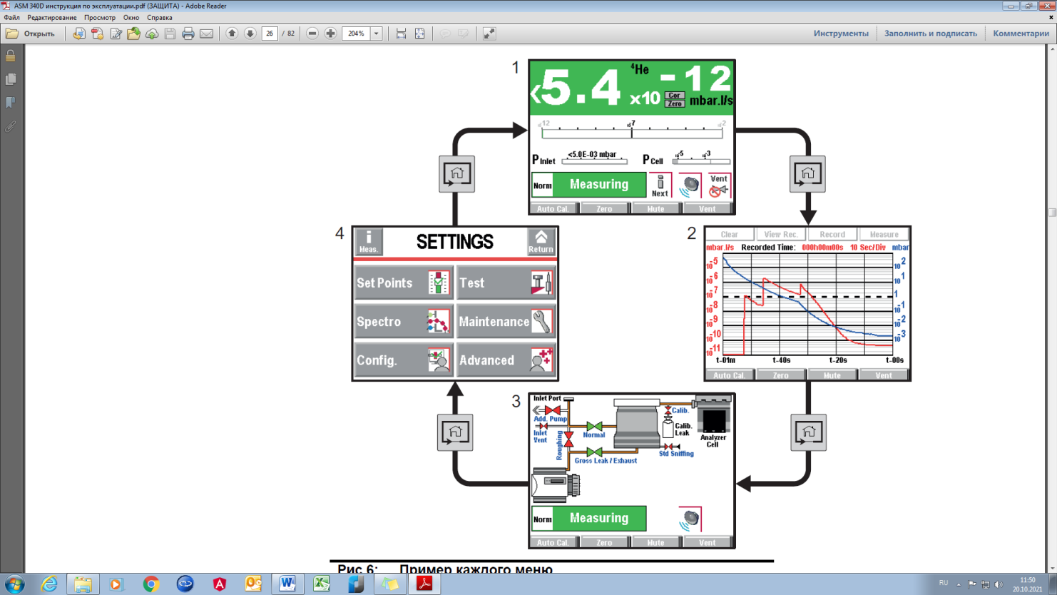 лавная страница, информация относящаяся к работе с объектом;
Универсальный высокочувствительный гелиевый течеискатель с пластинчато-роторным насосом и скоростью откачки 15 м3/ч.
Преимущества:
- быстрое время отклика благодаря самому большому пластинчато-роторному насосу в своём классе
- высокая производительность вакуумного насоса для универсального использования
- единственный течеискатель в своём классе способный обнаружить течь начиная со 100 мбар
- впечатляющие результаты в режиме работы по методу щупа, с минимальным регистрируемым потоком 5·10-10 Па м3/с
- встроенная карта памяти SD для записи и загрузки параметров
- могут применяться уже имеющиеся у Вас аксессуары
- полный спектр коммуникационных разъёмов ввода / вывода
- простое управление, интуитивно понятное меню и большой цветной сенсорный экран
- низкие эксплуатационные расходы благодаря прочной конструкции
Технические характеристики:
- Входной фланец: DN 25 ISO-KF
- Методы испытаний: Вакуумный метод и метод щупа
- Рабочие газы: 4He, 3He, H2
- Минимальный регистрируемый поток Гелия (вакуумный метод): <5·10-13 Па м3/с
- Минимальный регистрируемый поток Гелия (метод щупа): 5·10-10 Па м3/с
- Скорость форвакуумной откачки: 15 м3/ч
- Скорость откачки по Гелию на входном фланце: 2,5 л/с
- Максимальное рабочее давление: 25 мбар
- Время выхода на рабочий режим (20°C): < 3 мин
- Интерфейсы: RS-232, опционально Ethernet, Bluetooth, USB
- I/O интерфейсы: Digital and analog I/O, Relays
- Языки: русский, английский, французский, немецкий, итальянский, испанский, японский, китайский, корейский
- Размеры: 393 x 547 x 375 мм
- Вес: 56 кг
- Электропитание: 220 В, 50 Гц
- Максимальная потребляемая мощность: 850 Вт
- Рабочая температура (вакуум): 0–45°C
- Рабочая температура (метод щупа): 0–40°C
ВОЗМОЖНЫ ДОПОЛНИТЕЛЬНЫЕ ОПЦИИ
 Скачать брошюру Pfeiffer Vacuum Гелиевые течеискатели
Назначение
Описание
Программное обеспечение
Знак утверждения типа
Комплектность
Сведения о методах измерений
Нормативные документы
Назначение
Течеискатели масс-спектрометрические гелиевые ASM (далее — течеискатели) предназначены для измерений потоков гелия при проведении неразрушающего контроля герметичности, а также для обнаружения мест нарушения герметичности (течей) различных систем и объектов, допускающих откачку внутренней полости или заполнение гелием либо смесью газов, содержащих гелий.
Описание
Принцип действия течеискателей основан на измерении ионного тока, пропорционального количеству ионизированных молекул пробного газа.
Вакуумная система течеискателя соединяется с системой или объектом, для которого проводится контроль герметичности или обнаружение места нарушения герметичности (далее — испытуемый объект). В зависимости от выбранного режима работы течеискателя производится откачка внутренней полости или заполнение пробным газом (по умолчанию — гелий) вакуумной системы течеискателя в совокупности с испытуемым объектом. Молекулы пробного газа, проникающие через места нарушения герметичности испытуемого объекта, попадают в масс-спектрометрический анализатор течеискателя (далее — анализатор), где ионизируются направленным потоком заряженных частиц от ионного источника. Ионизированные молекулы (далее — ионы) газа ускоряются в магнитном поле анализатора, перемещаясь по окружности, радиус которой зависит от относительной атомной массы иона газа, и фокусируются на ионном коллекторе (мишени), создавая ионный ток. В течеискателях предусмотрены режимы работы «Вакуум. метод» -«Нормальный», «Вакуум. метод» — «Высокая чувствительность» (режим предусмотрен только в модификациях ASM 390 и ASM 392), «Вакуум. метод» — «Массивная течь» и «Метод щупа». Режимы отличаются тем, что пробный газ попадает на разные ступени турбомолекулярного насоса, в связи с чем выделяют независимые каналы измерений.
В корпусе течеискателя находятся масс-спектрометрический анализатор, настроенный на регистрацию ионов пробного газа, вакуумная система, электроника течеискателя и интерфейс оператора (жидкокристаллический дисплей). Подключение испытуемого объекта к вакуумной системе течеискателя осуществляется с помощью присоединительного фланца (испытательный порт), расположенного на верхней панели корпуса течеискателя.
Течеискатели выпускаются в 5 модификациях: ASM 340 W (где «W» — WET
— масляный насос), ASM 340 D (где «D» — DRY — безмасляный насос), ASM 340 I (где «I» означает «без форвакуумного насоса»), ASM 390, ASM 392. Модификации отличаются диапазоном показаний, внешним видом, характеристиками питания, габаритными размерами, массой и комплектностью.
Пломбирование течеискателей не предусмотрено.
Заводской номер течеискателя наносится на одну из боковых панель течеискателя. Общий вид течеискателей представлен на рисунках 1 -3.
Программное обеспечение
Течеискатели имеют встроенное программное обеспечение (ПО), разработанное изготовителем специально для решения задач измерения потоков гелия при проведении неразрушающего контроля герметичности, обнаружения мест нарушения герметичности различных систем и объектов, допускающих откачку внутренней полости, заполнение гелием либо смесью газов, содержащих гелий.
ПО течеискателей выполняет следующие функции:
— управление работой вакуумной системы течеискателя (работой вакуумных насосов, клапанов);
— управление работой масс-спектрометрического анализатора (определение чувствительности, настройка на пик гелия);
— сбор, обработка и передача измерительной информации на устройство вывода;
— отображение измерительной информации;
— автоматическая диагностика состояния течеискателя.
Идентификационные данные ПО представлены в таблице 1.
Влияние ПО течеискателей учтено при нормировании метрологических характеристик.
Уровень защиты ПО от преднамеренных или непреднамеренных изменений течеискателей — «средний» в соответствии с Р 50.2.077-2014.
Таблица 1 — Идентификационные данные программного обеспечения
|
Идентификационные данные (признаки) |
Значение |
|
Идентификационное наименование ПО |
ASM |
|
Номер версии (идентификационный номер) ПО, не ниже |
1.0.00 |
|
Цифровой идентификатор ПО |
— |
Таблица 2 — Метрологические характеристики
|
Наименование характеристики |
Значение |
|
Диапазон измерений потока газа в вакууме по входу течеискателя (при работе в режимах «Вакуум. метод» — «Нормальный», «Вакуум. метод» -«Высокая чувствительность» и «Вакуум. метод» -«Массивная течь»), Пам3/с* |
от 110-12 до 1 • 10-1 |
|
Диапазон показаний потока газа в вакууме по входу течеискателя (при работе в режимах «Вакуум. метод» — «Нормальный», «Вакуум. метод» -«Высокая чувствительность» и «Вакуум. метод» -«Массивная течь»), Пам3/с* |
от 5 10-13 до 1 • 10-1 |
|
Диапазон показаний потока газа в вакууме при работе в режиме «Метод щупа», Пам3/с* — ASM 340 W, ASM 340 D, ASM 340 I — ASM 390, ASM 392 |
от 5 10-10 до 1 • 10-2 от 1-10″9 до 1-10″2 |
|
Пределы допускаемой относительной погрешности измерений потока газа в вакууме по входу течеискателя, % — при работе в режимах «Вакуум. метод» — «Нормальный» и «Вакуум. метод» — «Высокая чувствительность» (где Qнпи — значение нижнего предела измерений, Пам3/с*; Оизм — значение измеренного потока, Пам3/с*) — при работе в режиме «Вакуум. метод» — «Массивная течь» — при работе в режиме «Метод щупа» |
±(0,15 + Qнпи/Qизм)• 100 ±50 не нормируется |
|
*Производная единица величины потока газа в вакууме Па-м 3/с образована в соответствии с п. 5.2.1 ГОСТ 8.417-2002 на основании уравнения связи (измерений), полученного из уравнения состояния идеального газа. |
Таблица 3 — Основные технические характеристики
|
Наименование характеристики |
Значение |
|
Скорость форвакуумной откачки, м3/ч — ASM 340 W |
15 |
|
— ASM 340 D |
3,4 |
|
— ASM 340 I |
-* |
|
— ASM 390, ASM 392 |
35 |
|
Время установления выходного сигнала, мин, не более |
3 |
|
Параметры электрического питания: |
|
|
— напряжение переменного тока, В |
220±22 |
|
— частота переменного тока, Г ц |
50±1 |
|
Потребляемая мощность, В А, не более |
|
|
— ASM 340 W, ASM 340 D |
600 |
|
— ASM 340 I |
350 |
|
— ASM 390, ASM 392 |
800 |
|
*В зависимости от потребительской форвакуумной насосной системы скорость форвакуумной откачки может меняться от 1 до 100 м3/ч. |
|
Наименование характеристики |
Значение |
|
Габаритные размеры, мм, не более (длина; ширина; высота) — ASM 340 W, ASM 340 D, ASM 340 I |
547;393; 375 |
|
— ASM 390, ASM 392 |
455; 1072; 1025 |
|
Масса, кг, не более |
|
|
— ASM 340 W, ASM 340 D |
45 |
|
— ASM 340 I |
32 |
|
— ASM 390 |
125 |
|
— ASM 392 |
130 |
|
Условия эксплуатации: — диапазон рабочих температур окружающего воздуха, °С |
от +10 до +35 |
|
— относительная влажность воздуха, %, не более |
80 |
|
— атмосферное давление, кПа |
от 84 до 106,7 |
|
Средняя наработка до отказа, ч |
15000 |
|
Средний срок службы, лет |
12 |
Знак утверждения типа
наносится на корпус течеискателей методом наклейки или иным способом, на титульный лист руководств по эксплуатации типографским способом.
Комплектность
Таблица 4 — Комплектность течеискателей
|
Наименование |
Обозначение |
Количество |
|
Течеискатель |
в соответствии с заказом |
1 шт. |
|
Руководство по эксплуатации |
в соответствии с заказом |
1 экз. |
Сведения о методах измерений
приведены в документах «Течеискатели масс-спектрометрические гелиевые ASM 340 W, ASM 340 D, ASM 340 I. Руководство по эксплуатации» раздел 6, «Течеискатели масс-спектрометрические гелиевые ASM 390, ASM 392. Руководство по эксплуатации» раздел 6.
Нормативные документы
ГОСТ 28517-90 Контроль неразрушающий. Масс-спектрометрический метод течеискания. Общие требования
ГОСТ Р 53177-2008 Вакуумная техника. Определение характеристик масс-спектрометрического метода контроля герметичности Техническая документация «Pfeiffer Vacuum», Франция


В наличии
Характеристики
-
Страна
Германия
-
Мощность, кВт
0,85
-
Напряжение, В
220
-
Габаритные размеры, мм
547x375x393
-
I/O интерфейсы
Basic 15 pins I/O
-
Рабочие газы
4He;3He;H2
-
Интерфейсы
RS-232, Ethernet, Bluetooth
-
Скорость форвакуумной откачки, м3/ч
15
-
Скорость откачки по гелию, л/с
2,5
-
Класс защиты
IP20
-
Максимальное рабочее давление, мбар
25
-
Температурный режим, °С
от 0 до 45
-
Методы испытаний
Вакуумный метод и метод щупа
-
Минимальный регистрируемый поток гелия — вакуумный метод, Па·м3/с
5×10^(-13)
-
Минимальный регистрируемый поток гелия — метод щупа, Па·м3/с
5×10^(-10)
-
Время запуска, сек
180
-
Уровень шума, дБ
52
-
Вес, кг
56
-
Присоединительный патрубок
DN 25 ISO-KF
Условия оплаты и доставки
Оплата
Юридические лица
- Безналичный расчет
Физические лица
- Безналичный расчет
- Наличный расчет в офисе продаж
Доставка
- Самовывоз со склада ЭРСТВАК
- Доставка транспортной
компанией
Оформить заказ
Для оформления заказа заполните форму и наш инженер свяжется с вами в ближайшее время!
- П одготовить течеискатель ASM 340 (ТИ) к работе, для чего:
- проверить уровень масла в форвакуумном насосе ТИ по уровнемеру;
- соединить корпус ТИ с шиной заземления рабочего места;
- сетевым кабелем (может лежать в ящике, расположенном в верхней части корпуса ТИ) подключить ТИ к электросети напряжением 220В.
ВНИМАНИЕ! Управление сенсорным экраном осуществлять только руками без использования твердых предметов, таких как ручки, отвертки и т.п.
Перемещать, подвигать, стучать по столу на котором установлен ТИ запрещается!
- Включить переключатель питания, на левой боковой панели корпуса ТИ в положение «I». На сенсорном экране панели управления загорится подсветка. Процесс вывода на режим ожидания происходит автоматически.
При появлении на экране надписи: «Storage Delay (35 days):10 min» нажать кнопку [START/Stend-by] ![]() на панели управления.
на панели управления.
ТИ будет готов когда на сенсорном экране отобразится команда «ОЖИДАНИЕ».
- Нажать кнопку [START/Stend-by] на панели управления. ТИ автоматически проведет откачку входа, экран станет цветным и отобразится команда «ИЗМЕРЕНИЕ».
- Открыть клапан KF25 на входной линии подстыковки ТИ.
- Открыть контрольную течь (Qкт) на камере, дождаться стабилизации показаний на дисплее ТИ (≈ 7-10 мин.), в зависимости от объема камеры время стабилизации может быть увеличено.
- Несколькими нажатиями клавиши «окна» найти в нижней строке функцию «КОРРЕКЦИЯ»,
и нажатием кнопки войти. - Повторным нажатием кнопки включить коррекцию.
Индикатор включения/отключения
коррекции
- Выбрать параметр «ВЕЛИЧИНА». Используя клавиши «плюс», «минус» и «множитель» установить такое значение коррекции, чтобы отображаемое на ТИ значение течи совпадало со значением указанным на контрольной течи (установленной на камере).
Путем нажатия кнопок ![]() , установить требуемое значение.
, установить требуемое значение.
Настройка уставки:
- Нажать кнопку «ДОМОЙ» , вернуться на рабочий экран.
- Закрыть Qкт, дождаться установившихся показаний (≈ 3-5 мин.), в зависимости от объема камеры время стабилизации может быть увеличено.
Индикатор включения/
отключения
«НОЛЬ»
- Кнопкой нажать вкладку «НОЛЬ» в нижнем меню управления. Если функция «ноль» отсутствует в нижней строке, то нажатием на клавишу «Окна» вывести функцию «ноль» на экран и применить её.
- Открыть Qкт, дождаться стабилизации показаний, убедиться что показания ТИ совпадают с Qкт. Если есть не значительное отклонение, кнопкой «КОРРЕКЦИЯ» подредактировать значение (см. пункт 8).
- Закрыть Qкт дождаться стабилизации фона.
- Открытием/закрытием Qкт еще раз убедиться в точности настройки ТИ.
- Установить порог отбраковки, для чего несколькими нажатиями клавиши «окна» найти в нижней строке функцию «УСТАВКА» используя клавиши «плюс», «минус» и «множитель» установить уровень отбраковки изделия.
- . Провести контроль герметичности согласно поданной заявки и Программы и методики 154.ПМ003.
— заправить ОИ пробным зазом;
— выдержать ОИ под пробным давлением установленное время;
— зафиксировать показания течеискателя отображаемые на дисплее;
— записать измеренное значение в журнал;
— удалить пробный газ из ОИ;
- По завершению работы:
ВНИМАНИЕ!!!
Оператор может перемещать или обслуживать ТИ только после его полной остановки. Когда выключатель в положении «О», необходимо:
- дождаться полного отключения экрана панели управления перед началом каких-либо работ с оборудованием.
- Отключить сетевой кабель.
Краткое описание функциональности кнопок
- с енсорный экран
- [START/Stand-by] старт/остановка работы с объектом
- «домой» смена меню, возврат из любого меню на главную страницу
- подключение стандартного пульта (доп.опция)
- доступ к функциям постоянного использования (позволяет получить доступ к функциям ТИ при возникновении проблем с сенсором панели)
- отображение уровня функциональных кнопок
- «окна» управление строкой нижнего меню
- г лавная страница, информация относящаяся к работе с объектом;
- график, мониторит и регистрирует объем течи и/или давление на входе;
- мнемосхема, принципиальная схема приборов и состояния клапанов;
- настройка, настройка параметров прибора.
Универсальный высокочувствительный гелиевый течеискатель с пластинчато-роторным насосом и скоростью откачки 15 м3/ч.
Преимущества:
- быстрое время отклика благодаря самому большому пластинчато-роторному насосу в своём классе
- высокая производительность вакуумного насоса для универсального использования
- единственный течеискатель в своём классе способный обнаружить течь начиная со 100 мбар
- впечатляющие результаты в режиме работы по методу щупа, с минимальным регистрируемым потоком 5·10-10 Па м3/с
- встроенная карта памяти SD для записи и загрузки параметров
- могут применяться уже имеющиеся у Вас аксессуары
- полный спектр коммуникационных разъёмов ввода / вывода
- простое управление, интуитивно понятное меню и большой цветной сенсорный экран
- низкие эксплуатационные расходы благодаря прочной конструкции
Технические характеристики:
- Входной фланец: DN 25 ISO-KF
- Методы испытаний: Вакуумный метод и метод щупа
- Рабочие газы: 4He, 3He, H2
- Минимальный регистрируемый поток Гелия (вакуумный метод): <5·10-13 Па м3/с
- Минимальный регистрируемый поток Гелия (метод щупа): 5·10-10 Па м3/с
- Скорость форвакуумной откачки: 15 м3/ч
- Скорость откачки по Гелию на входном фланце: 2,5 л/с
- Максимальное рабочее давление: 25 мбар
- Время выхода на рабочий режим (20°C): < 3 мин
- Интерфейсы: RS-232, опционально Ethernet, Bluetooth, USB
- I/O интерфейсы: Digital and analog I/O, Relays
- Языки: русский, английский, французский, немецкий, итальянский, испанский, японский, китайский, корейский
- Размеры: 393 x 547 x 375 мм
- Вес: 56 кг
- Электропитание: 220 В, 50 Гц
- Максимальная потребляемая мощность: 850 Вт
- Рабочая температура (вакуум): 0–45°C
- Рабочая температура (метод щупа): 0–40°C
ВОЗМОЖНЫ ДОПОЛНИТЕЛЬНЫЕ ОПЦИИ
Скачать брошюру Pfeiffer Vacuum Гелиевые течеискатели
![]()
- Group
- Press
- Careers
-
- DE
- EN
- 中国
- 대한민국
- Products
-
Vacuum Generation
- Rotary Vane Pumps
- Diaphragm Pumps
- Scroll Pumps
- Screw Pumps
- Multi-stage Roots Pumps
- Roots Pumps
- Turbopumps
- Pumping Stations
-
Measurement & Analysis
- Measurement
- Analysis Equipment
-
Leak Detection
- Leak Detectors
- Leak testing with air
- Leak testing & CCIT solutions for Pharma
- Leak Detection Page
-
Valves, Chambers & Components
- Vacuum Valves
- Vacuum Chambers
- Components
- Feedthroughs
- Manipulators
-
Systems
- Contamination
Management Solutions - Helium Leak Detection Systems
- Helium Recovery Units
- Multi-Stage Vacuum-
Process - Calibration Systems
- Contamination
-
Select & Request Platform
Request the right vacuum equipment, for example vacuum pumps, leak detectors or mass spectrometers, directly from you sales engineer.
- Simple and detailed selection options
- Shopping list function for your projects
- Clearly arranged user account
Register now
-
- Markets
- Know How
-
Introduction to Vacuum Technology
- General
- Fundamentals
- Influences in real vacuum systems
-
Basic calculations
- General
- Calculations
- Piping conductivities
-
Mechanical components in vacuum
- General
- Materials
- Connections
- Vacuum chambers
- Components and feedthroughs
- Valves
- Manipulators and mechanical feedthroughs
-
Vacuum generation
- Vacuum pumps — working principles
and properties - Rotary vane vacuum pumps
- Diaphragm vacuum pumps
- Screw vacuum pumps
- Multi-stage Roots pumps —
Vacuum generation - Multi-stage Roots pumps —
Vacuum processes - Roots vacuum pumps
- Side channel high vacuum pumps
- Turbomolecular pumps
- Vacuum pumps — working principles
-
Vacuum measuring equipment
- Fundamentals of total pressure measurement
- Application notes
- Portfolio overview
-
Mass spectrometers and residual gas analysis
- Introduction, operating principle
- Sector field mass spectrometers
- Quadrupole mass spectrometers (QMS)
- Portfolio overview
-
Leak detection
- General
- Leak detection with tracer gases
- Application notes
- Portfolio overview
- Industrial leak testing
-
Contamination management solutions
- Introduction
- Contamination
- The nature of AMC
- From surface molecular contamination (SMC) to
defects - Portfolio overview
-
Lists
- Literature
- Figures
- Tables
- Formulas
-
- Solutions
- Service
-
Online Services
- Service Request
- Virtual Service Management
- Document Finder
-
Service Portfolio
- Product Service
- Genuine Parts & Tools
- On-site Service
- Calibration Service
- Service Level Agreements
-
Leak Testing Services
-
Training
- General Information
- Overview of Courses
- Online Registration / Request
-
Worldwide Service Contact
-
Online Service Portal
Create service tickets and find all product-related documents. Organize service intervals and maintenance of your vacuum equipment via the Virtual Service Management Portal «VSM» and save time and money!
Learn more
-
- Download Center
- Contact
- USA
-
- Sales/Application Support Team
- Refurbished equipment
- New Products
- Career opportunities
-
- Sverige
-
- Service Center
-
- Italia
-
- Contatti commerciali
- Centri di assistenza
-
- France
- 中国
-
- 新闻发布
- 中文宣传册
- 人才招聘
-
- Česká republika
-
- Servis
-
- 대한민국
-
- 새소식
-
- 台灣
- Search
![]()
- Home
- Products
- Leak Detection
- Leak Detectors
- Multipurpose
- ASM 340
- ASM 340, 200/240 V, European mains cable


ASM 340, 200/240 V, European mains cable
Order number: JSVA02A0MH9A
- Powerful rotary vane pump with 15 m3/h backing pump capacity
- 2.5 l/s helium pumping speed
- 200/240 V operating voltage, European power cable
- Modern, bright and detachable color touch screen
- Large internal memory and data output via USB port on the display
- Wired or wireless remote control and sniffer probes available as accessories
- Technical data
- Dimensions
- Accessories
- Downloads
| Backing pump capacity | 15 m³/h | 8.83 cfm | 250 l/min |
| Connection flange (in) | DN 25 ISO-KF |
| Detectable gases | 4He 3He H2 |
| Dimensions (L x W x H) | 547 x 375 x 389 mm | 21.54 x 14.76 x 15.31 inch |
| I/O interfaces | RS-232 |
| Input voltage(s) | 200 – 240 V AC, 50/60 Hz |
| Interface: Connection, device side | Standard 15 pins I/O |
| Minimum detectable leakage rate for helium (sniffing leak detection) | 5 · 10-10 Pa m3/s | 3.75 · 10-9 Torr l/s | 5 · 10-9 mbar l/s |
| Minimum detectable leakage rate for helium (vacuum leak detection) | 1 · 10-13 Pa m³/s |
| Operating temperature (sniffing test) | 0-35 °C | 32-95 °F | 273-308 K |
| Operating temperature (vacuum test) | 0-45 °C | 32-113 °F | 273-318 K |
| Power consumption max. | 850 W |
| Protection degree | IP20 |
| Pumping speed for He | 2.5 l/s |
| Sound pressure level | 52 dB(A) |
| Start-up time (20°C) without calibration | 3 min |
| Test method | Vacuum and sniffing leak detection |
| Weight | 56 kg | 123.46 lb |

-
Cables
-
Mains cables / Power cords
-
-
Connections
-
Control Devices
-
Protection
-
Sniffing/Spraying
-
Helium pistols/ spray guns
-
Sniffer probes
LP 503, sniffer probe with standard tip, 3 m BG449207-T LP 505, sniffer probe with standard tip, 5 m BG449208-T LP 510, sniffer probe with standard tip, 10 m BG449209-T Sniffer probe, 5 m hose length and rigid 9 cm nozzle SNC1E1T1 Sniffer probe, 10 m hose length, rigid 9 cm nozzle SNC2E1T1 -
-
Transport
-
Transportation accessories
-
Transport cart
-
Your local contact
BLM Synergie
Elektrozavodskaya str. 24107023 Moscow
Russia
write message