SIMATIC NET
AS-Interface Überspannungsschutzmodul
AS-Interface Overvoltage Protection Module
Module Parasurtension AS-Interface
Módulo de Protección Contra Sobretensiones AS-Interface
Modulo di Protezione da Sovratensioni AS-Interface
Módulo de Proteção Contra Sobretensão AS-Interface
Aşırı Gerilim Koruma Modülü AS-Interface
AS-Interface блок защиты от перенапряжений
AS-Interface 过电压防护模块
Betriebsanleitung
Instruções de Serviço
Deutsch
Vor der Installation, dem Betrieb oder der
Wartung des Geräts muss diese Anleitung
gelesen und verstanden werden.
GEFAHR
!
Gefährliche Spannung.
Lebensgefahr oder schwere
Verletzungsgefahr.
Vor Beginn der Arbeiten Anlage und Gerät
spannungsfrei schalten.
VORSICHT
Eine sichere Gerätefunktion ist nur mit
zertifizierten Komponenten gewährleistet.
Español
Leer y comprender este instructivo antes de
la instalación, operación o mantenimiento
del equipo.
PELIGRO
!
Tensión peligrosa.
Puede causar la muerte o lesiones
graves.
Desconectar la alimentación eléctrica antes
de trabajar en el equipo.
PRECAUCIÓN
El funcionamiento seguro del aparato sólo
está garantizado con componentes
certificados.
Türkçe
Cihazın kurulumundan, çalıştırılmasından
veya bakıma tabi tutulmasından önce, bu
kılavuzun okunmuş ve anlaşılmış olması
gerekmektedir.
TEHLİKE
!
Tehlikeli gerilim.
Ölüm tehlikesi veya ağır yaralanma
tehlikesi.
Çalışmalara başlamadan önce, sistemin ve
cihazın gerilim beslemesini kapatınız.
ÖNEMLİ DİKKAT
Cihazın güvenli çalışması ancak sertifikalı
bileşenler kullanılması halinde garanti
edilebilir.
Technical Assistance:
Telephone: +49 (0) 911-895-5900 (8°° — 17°° CET)
E-mail: technical-assistance@siemens.com
Internet: www.siemens.de/lowvoltage/technical-assistance
GWA 4NEB 333 1285-10 DS 02
Bestell-Nr. / Order No.: 3ZX1012-0KB08-3AA2
Operating Instructions
İşletme kılavuzu
Read and understand these instructions
before installing, operating, or maintaining
the equipment.
DANGER
!
Hazardous voltage.
Will cause death or serious injury.
Turn off and lock out all power supplying this
device before working on this device.
CAUTION
Reliable functioning of the equipment is only
ensured with certified components.
Leggere con attenzione queste istruzioni
prima di installare, utilizzare o eseguire
manutenzione su questa apparecchiatura.
PERICOLO
!
Tensione pericolosa.
Può provocare morte o lesioni gravi.
Scollegare l’alimentazione prima di
eseguire interventi sull’apparecchiatura.
CAUTELA
Il funzionamento sicuro dell’apparecchiatura
è garantito soltanto con componenti
certificati.
Перед установкой, вводом в
эксплуатацию или обслуживанием
устройства необходимо прочесть и
понять данное руководство.
ОПАСНО
!
Опасное напряжение.
Опасность для жизни или
возможность тяжелых травм.
Перед началом работ отключить подачу
питания к установке и к устройству.
ОСТОРОЖНО
Безопасность работы устройства
гарантируется только при использовании
сертифицированных компонентов.
Instructions de service
Инструкция по эксплуатации
English
Italiano
Русский
3RK1901-1GA01
s
IP 67
Instructivo
Istruzioni operative
使用说明
Français
Ne pas installer, utiliser ou intervenir sur cet
équipement avant d’avoir lu et assimilé les
présentes instructions et notamment les
conseils de sécurité et mises en garde qui y
figurent.
DANGER
!
Tension électrique.
Danger de mort ou risque de blessures
graves.
Mettre hors tension avant d’intervenir sur
l’appareil.
PRUDENCE
La sécurité de fonctionnement de l’appareil
n’est garantie qu’avec des composants
certifiés.
Português
Ler e compreender estas instruções antes
da instalação, operação ou manutenção do
equipamento.
PERIGO
!
Tensão perigosa.
Perigo de morte ou ferimentos graves.
Desligue a alimentação elétrica e proteja
contra o religamento, antes de iniciar o
trabalho no equipamento.
CUIDADO
O funcionamento seguro do aparelho
apenas pode ser garantido se forem
utilizados os componentes certificados.
中文
安装、使用和维修本设备前必须先阅
读并理解本说明。
危险
!
危险电压。
可能导致生命危险或重伤危险。
操作设备时必须确保切断电源。
小心
只有使用经过认证的部件才能保证设
备的正常运转。
Fax: +49 (0) 911-895-5907
Last update: 07 December 2010
Лучший выбор для универсальных сетей AS-i.
Ведущее устройство, блок питания, а также различные стандартные и безопасные станции (ведомые устройства) составляют основу каждой системы AS-i. Ведущее устройство обеспечивает обмен данными с ведомыми устройствами посредством циклического опроса. Блоки питания AS-i снабжают энергией ведомые устройства и датчики сети.
Сети AS-Interface могут быть подключены к контроллеру SIMATIC, SINUMERIK или другим контроллерам очень удобным для пользователя способом: с помощью модуля CM AS-i Master ST в ET 200SP для подключения ко всем контроллерам и для установки любого размера. С ведущим модулем AS-i на базовом контроллере S7-1200 для небольших решений автоматизации. Или с другими ведущими модулями AS-i от Siemens для других приложений. Интеграция так же проста, как и с другими модулями расширения контроллеров SIMATIC.
Ключевые данные по сети AS-i
- Количество рабов: до 62
- Количество входов / выходов: до 496 входов и 496 выходов
- Топология: любая, линия, звезда, дерево
- Среда: неэкранированная двухпроводная линия для передачи данных и энергии
- Длина линии: стандартно 100 м, с возможностью расширения с помощью повторителя и удлинителя
- Время цикла: 5 мс (типичное)
- Передача данных: цифровые и аналоговые значения
Поставщик комплексных решений
Мы предлагаем полный набор компонентов AS-i, от ведущего устройства SIMATIC, блоков питания и ведомых устройств до системных компонентов. Ассортимент ведомых устройств AS-i предлагает все: от простых и безопасных модулей ввода / вывода для полевых устройств и шкафа управления до кнопок и сигнальных столбцов, а также позиционных переключателей с подключением AS-i вплоть до мощных пускателей двигателей и преобразователей частоты.
- Полный ассортимент продуктов AS-i для стандартных шин и технологий безопасности от одних рук
- Последовательная интеграция устройств AS-i в концепции программирования и диагностики SIMATIC, а также в среду разработки TIA Portal.
- Интеграция приложений ASIsafe в программирование безопасности SIMATIC и SINUMERIK
- Интеграция подчиненных сетей AS-i в АСУ ТП PCS 7
- Глобальная логистика запасных частей, консультации и сервис

AS-Interface according to EN 50295
|
6/2 |
Introduction |
|
6/2 |
Transmission technology |
|
6/3 |
Configuration example |
|
6/4 |
System components |
|
6/5 |
Technical specifications |
|
6/6 |
A/B technique |
|
6/8 |
AS-Interface Safety at work |
|
6/8 |
Introduction |
|
6/9 |
AS-Interface safety monitors |
|
6/11 |
AS-Interface safe compact modules |
|
6/15 |
AS-Interface position switches |
|
6/18 |
AS-Interface cable-operated switches |
|
6/19 |
AS-Interface light curtains and |
|
light arrays for Category 4 |
|
|
6/24 |
AS-Interface laser scanner LS4 |
|
6/30 |
AS-Interface EMERGENCY STOP |
|
pushbuttons |
|
|
6/30 |
Accessories |
|
AS-Interface Master |
|||
|
6/31 |
Masters for SIMATIC S5 |
||
|
6/31 |
CP 2430 |
||
|
6/33 |
Masters for SIMATIC S7 |
||
|
6/33 |
CP 142-2 |
||
|
6/35 |
CP 243-2 |
||
|
6/37 |
CP 343-2 |
||
|
6/39 |
CP 343-2 P |
||
|
ST 70 1) |
Masters for SIMATIC C7 |
||
|
Sec. 8 2) |
AS-Interface network transitions |
||
|
DP/AS Interface Link 20E |
|||
|
DP/AS Interface Link 65 |
|||
|
AS-Interface Slaves |
|||
|
6/41 |
I/O modules for operation in the field |
||
|
6/41 |
Introduction |
||
|
6/43 |
Digital I/O modules IP67 – K60 |
||
|
6/51 |
Digital I/O modules IP68 / IP69K – K60R |
||
|
6/56 |
Digital I/O modules IP67 – K45 |
||
|
6/64 |
Digital I/O modules IP67 – |
||
|
application modules |
|||
|
6/71 |
Analog I/O modules IP67 – K60 |
||
|
6/74 |
Pneumatic I/O modules |
||
|
6/75 |
I/O modules for operation |
||
|
in IP20 control cabinet |
|||
|
6/75 |
Introduction |
||
|
6/77 |
SlimLine |
||
|
6/88 |
F90 module |
||
|
6/93 |
Flat module |
||
|
6/94 |
Special integrated solutions |
||
|
6/94 |
AS-Interface Communication modules |
|
AS-Interface Slaves (continued) |
|
|
6/98 |
Modules with special functions |
|
6/98 |
Counter modules |
|
6/100 |
Earth fault detection modules |
|
6/103 |
Overvoltage protection module |
|
6/105 |
AS-Interface motor starters and |
|
IP65/67 load feeders |
|
|
6/105 |
AS-Interface compact starters IP65 |
|
(400 V AC) |
|
|
6/113 |
AS-Interface motor starters IP67 (24 V DC) |
|
6/116 |
ECOFAST motor and soft starter |
|
6/117 |
AS-Interface motor starters and |
|
IP20 load feeders |
|
|
6/117 |
Load feeder modules IP20 |
|
LV 10 3) |
AS-Interface Direct/Reverse Starter |
|
6/121 |
SIRIUS soft starters |
|
LV 10 3) |
Communications capable contactors |
|
55 to 250 kW |
|
|
LV 10 3) |
Double relays and transformers |
|
6/122 |
SIGNUM pushbuttons and |
|
indicator lights |
|
|
6/122 |
AS-Interface F-Adapter for |
|
EMERGENCY STOP command devices |
|
|
6/123 |
AS-Interface enclosure |
|
6/124 |
AS-Interface customized enclosures |
|
and front panel modules |
|
|
6/133 |
AS-Interface LED displays |
|
6/134 |
AS-Interface for LOGO! |
|
LV 10 3) |
AS-Interface signal columns |
|
6/135 |
AS-Interface power supply units |
|
6/135 |
Introduction |
|
6/136 |
Power supply units IP20 |
|
6/141 |
Power supply units IP65 |
|
6/143 |
Transmission media |
|
6/143 |
AS-Interface shaped cable |
|
6/145 |
System components and accessories |
|
6/145 |
Repeater/Extender |
|
6/147 |
Addressing units |
|
6/149 |
Diagnostic units |
|
6/151 |
Miscellaneous accessories |
|
6/152 |
Documentation |
|
1) |
see Catalog ST 70 |
|
”Products for Totally Integrated |
|
|
Automation and Micro Automation“ |
|
|
2) |
see Section 8 |
|
3) |
see Catalog LV 10 |
|
”Controlgear for Industry“ |
Siemens IK PI . 2004
AS-Interface
Introduction
Transmission technology
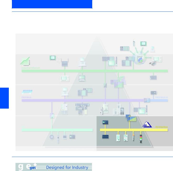
■Overview
Transmission method
A significant feature of the AS-Interface technology is the use of a common, two-wire cable for data transmission and distribution of auxiliary power to sensors/actuators.
An AS-Interface power supply unit, which meets the requirements of the AS-Interface transmission technology, is used for this system. The AS-Interface shaped cable provides mechanical coding and thus prevents polarity reversal; penetration terminals are used for simple contacting.
6
■Benefits
Cabinets that were previously overflowing with complicated control line wiring and marshalling distributors can now be replaced by AS-Interface.
The AS-Interface cable can be connected at any point, thanks to specially developed wiring and connection using the insulation displacement method.
This concept gives you tremendous flexibility and considerably cuts costs.
The AS-Interface is a single master system. Communications processors (CPs) are available for SIMATIC® systems which control process or field communication as masters.
The system expansion now allows double the quantity of slaves (max. 62) to be operated on AS-Interface. The analog values are now also preprocessed in the master. For direct connection of AS-Interface to PROFIBUS DP, DP/AS-Interface Link 20E is available. Using this DP/AS-Interface link, the AS-Interface can be used as a subnet for PROFIBUS DP.
The AS-Interface is an open standard. Leading manufacturers of actuators and sensors support AS-Interface worldwide. Interested companies can obtain the electrical and mechanical specifications from the AS-Interface Association on request.
|
AS-Interface |
|||
|
Introduction |
|||
Configuration examples |
|||
|
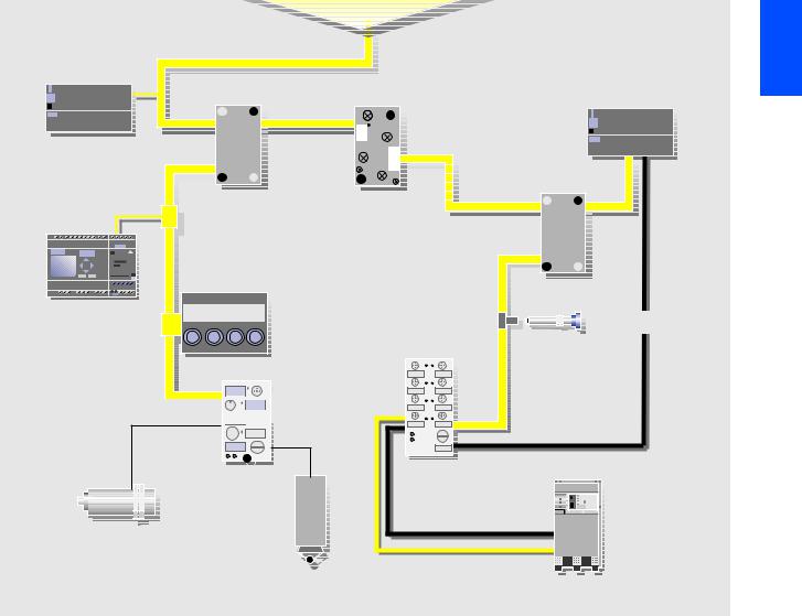
■Function |
|||
|
Operating modes |
AS-Interface slaves (according to analog profile 7.3 or 7.4) is just |
||
|
In general, the master interfaces distinguish between the follow- |
as easy as with digital slaves. |
||
|
ing operating modes: |
Command interface |
||
|
I/O data transfer |
In addition to the I/O data exchange with binary and analog AS- |
||
|
The inputs and outputs of the binary AS-Interface slaves are |
Interface slaves, the AS-Interface masters offer a range of addi- |
||
|
tional functions through the command interface. |
|||
|
read and written in this operating mode. |
|||
|
This means that, from user programs, slave addresses can be |
|||
|
Analog value transmission |
|||
|
assigned, parameter values can be transferred and diagnostic |
|||
|
The AS-Interface masters according to the Complete |
information can be read out. |
||
|
AS-Interface Specification V2.1 support integrated analog value |
|||
|
processing. This means that data exchange with analog |
|||
|
■Design |
|||
|
Process or field communication |
In practice this means: The installation runs without problems |
||
|
AS-Interface is used wherever individual actuators and sensors |
because data and power are transported through a single com- |
||
|
mon cable. No specialist know-how is required for installation |
|||
|
are physically distributed throughout the machine (e.g. in a bot- |
|||
|
and startup. In addition, the simple installation and clear struc- |
|||
|
tling plant or on a production line). |
|||
|
turing of the wiring and special cable design not only consider- |
|||
|
AS-Interface replaces complicated wiring harnesses and con- |
|||
|
ably reduce the risk of faults but also reduce service and main- |
|||
|
nects binary and analog actuators and sensors, such as proxim- |
|||
|
tenance costs. |
|||
|
ity switches, valves or indicator lights, to a controller (e.g. SI- |
|||
|
MATIC) or PC. |
|
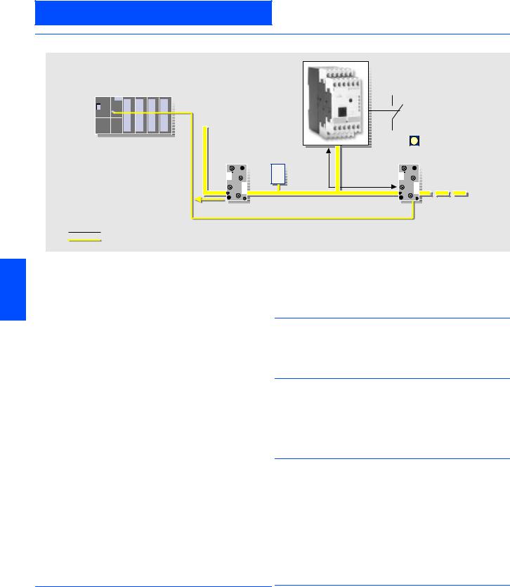
Connection via AS-Interface cable |
||
|
AS-Interface |
||
|
AS-Interface cable |
power section |
|
|
AS-Interface |
||
|
power section |
||
|
AS-Interface distributor |
Repeater |
100 max |
|
(without AS-Interface chip) |
m |
|
|
LOGO! |
AS-Interface distributor |
|
|
(without AS-Interface chip) |
||
|
Operator panel |
|
Branch M12 |
SONAR BERO |
|
|
with int. AS-Interface |
||
K60
K45

 (with AS-Interface chip)

 for connection of
 standard sensors
Compact starter IP 65
Standard sensor e.g. inductive BERO
Standard encoders e.g. position switches
Example of a system configuration

AS-Interface
Introduction
System components
■Overview
System components
Many system components are available to implement communications. The basic components of a system installation are:
•Master interfaces for central control units such as SIMATIC S5 and SIMATIC S7, distributed I/Os ET 200® M/X,
•AS-Interface shaped cables
•Network components such as repeaters/extenders
•The power supply unit for supplying power to the slaves, modules for connecting standard sensors/actuators
•Actuators and sensors with integrated ASIC slave
•Fail-safe modules for transmission of secure data through AS-Interface,
•Address programming device for setting the slave address.
ET 200M
S5-115U to 155U
Links
AS-Interface master for SIMATIC

AS-Interface
Introduction
Technical specifications
■Technical specifications
|
Standard |
EN 50295 |
|
Topology |
Bus, star or tree topology |
|
(like electrical installation) |
|
|
Transmission medium |
Unshielded two-wire cable |
|
(2 x 1.5 mm2) for data and |
|
|
auxiliary power |
|
|
Connection method |
Contacting of the AS-Interface |
|
cable using the insulation |
|
|
displacement method |
|
|
Permissible cable length max. |
100 m w/o repeater/extender |
|
500 m range with repeater/ |
|
|
extender (parallel connection |
|
|
of repeaters) |
|
|
Cycle time max. |
5 ms with full expansion, |
|
10 ms using A/B method |
|
|
Number of stations max. |
31 slaves accord. to Complete |
|
AS-Interface Spec. V2.0 ; |
|
|
62 slaves accord. to Complete |
|
|
AS-Interface Spec. V2.1 |
|
|
(A/B method), |
|
|
integrated analog value |
|
|
transmission |
|
■More information
Please note the operating framework conditions in each case for the specified SIMATIC NET products (Order No. 6GK…, 6XV1…), which you will find on the Internet page listed below.
Additional information is available in the Internet under:
http://www.siemens.de/simatic-net/ik-info
|
Number of binary |
Max. 124 I/124 O |
||
|
sensors/actuators |
modules according to spec. V2.0; |
||
|
Max. 248 I/186 O |
|||
|
modules according to spec. V2.1 |
|||
|
Access procedure |
Cyclical master-slave polling |
6 |
|
|
method, cyclical acceptance |
|||
|
by host (PLC, PC) |
|||
|
Error correction |
Identification and repetition of |
||
|
faulty messages |
|||
AS-Interface
A/B technique
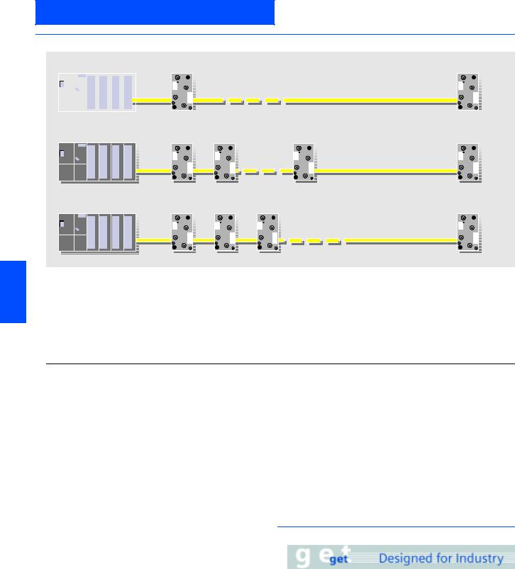
■Overview
|
Previously 31 nodes |
Slave 1 |
Slave 31 |
|||||||||
|
with A/B slaves max. 62 nodes: |
Slave 1A |
Slave 1B |
Slave 31A |
Slave 31B |
|
Mixed operation also permissible: |
Slave 1 |
Slave 2A |
Slave 2B |
Slave 31 |
The A/B technique concept
6 The AS-Interface specification 2.1 allows a doubling of network stations from 31 to 62. The 31 addresses that can be assigned in an AS-Interface network can be split into two mutually independent sub-addresses, e.g. in 1A and 1B.
If this is utilized for all 31 slaves, up to 62 slaves can be connected within an AS-Interface network. The so-called A/B slaves can each have up to four inputs and three outputs.
G_IK10_XX_20020
Another new feature of the new AS-Interface specification V2.1 is integrated analog value transfer. In this case, integrated means that no special function blocks are required in order to access the analog values. Accessing data is therefore just as easy in the case of analog values as it is with digital values. Integrated analog value transfer can be used with analog slaves that support Proifiles 7.3 and 7.4.
|
Slave type |
Number of slaves |
Number of inputs |
Number of outputs |
|
|
AS-Interface standard |
Standard slave |
Up to 31 |
31 x 4 = 124 |
31 x 4 = 124 |
|
AS-Interface version 2.1 |
A/B slave |
Up to 62 |
62 x 4 = 248 |
62 x 3 = 186 |
|
AS-Interface master |
Communication cycle |
To operate A/B slaves in an AS-Interface network, master modules working according to the specification 2.1 must also be used. The A/B technique is supported by the SIMATIC S7 masters and the DP/AS-Interface links from Siemens. To masters that do not support specification 2.1, only standard and A slaves can be connected.
The sub-address of A/B slaves is set to “A” by default.
Masters and slaves that are already working to the new specification are identified accordingly in the catalog.
Addressing A/B slaves
A/B slaves can be addressed like standard slaves via all commercial AS-Interface addressing units conforming to specification 2.1. AS-Interface addressing units that do not conform to the new specification 2.1 can readdress A/B slaves only as A slaves.
As far as addressing is concerned, an analog slave is like a standard slave. Up to 31 analog slaves can therefore be operated in one AS-Interface segment.
Standard slaves are polled in every cycle (max. cycle time: 5 ms).
If only an A or B slave is installed at an address, this slave is also polled in every cycle (max. cycle time: 5 ms).
If an A/B slave pair is installed at an address, slave A is polled in one cycle, slave B in the next (max. cycle time: 10 ms).
If only standard and/or A slaves are installed in a network, the cycle time is the same as for standard masters (max. cycle time:
5 ms).
■Benefits
• Lower costs for masters and power supply units
• Enhanced decentralization in installations with numerous, widely distributed signals
• Existing AS-Interface systems can be expanded further
AS-Interface
A/B technique
■Selection and Ordering data
Master according to Specification 2.1
CP 243-2
Master for SIMATIC S7-200
CP 343-2
Master for SIMATIC S7-300
CP 343-2 P
master for SIMATIC S7-300 configuration with STEP 7
6GK7 243-2AX01-0XA0
6GK7 343-2AH00-0XA0
6GK7 343-2AH10-0XA0
|
DP/AS-Interface Link 20E |
6GK1 415-2AA01 |
|||
|
Gateway for transition from AS-Interface to PROFIBUS DP |
||||
|
A/B slaves |
||||
|
K45 compact module |
||||
|
• 4 inputs |
||||
|
— M12 connection |
||||
|
3RK2 200-0CQ20-0AA3 |
||||
|
— M8 screw-type connection |
||||
|
3RK2 200-0CT20-0AA3 |
||||
|
— M8 snap-on connection |
||||
|
3RK2 200-0CU20-0AA3 |
||||
|
• 2 x 2 inputs |
||||
|
3RK2 200-0CQ22-0AA3 |
||||
|
• 3 outputs |
||||
|
3RK2 200-0CQ20-0AA3 |
3RK2 100-1EQ20-0AA3 |
|||
|
• 2 outputs / 2 inputs 1) |
||||
|
3RK2 400-1BQ20-0AA3 |
||||
|
K60 compact module |
||||
|
• 8 inputs /2 outputs |
||||
|
3RK2 400-1HQ00-0AA3 |
6 |
|||
|
• 8 inputs |
||||
|
3RK2 200-0DQ00-0AA3 |
||||
|
• 4 inputs/ 3 outputs |
||||
|
3RK2 400-1FQ03-0AA3 |
||||
|
3RK2 400-1HQ00-0AA3 |
||||
|
Slimline S22.5 |
||||
|
• 4 inputs |
||||
|
— Screw-type terminals 1) |
||||
|
3RK2 200-0CE02-0AA2 |
||||
|
— Cage Clamp terminals 1) |
||||
|
3RK2 200-0CG02-0AA2 |
||||
|
3RK2 200-0CE02-0AA2 |
||||
|
Slimline S45 |
||||
|
• 4 inputs/ 3 outputs |
||||
|
— Screw terminals |
||||
|
3RK2 400-1FE00-0AA2 |
||||
|
— Cage Clamp terminals |
3RK2 400-1FG00-0AA2 |
3RK2 400-1FE00-0AA2
1) Start of delivery: approx. end of 2003.
AS-Interface
AS-Interface Safety at work
Introduction
■Overview
Standard PLC Standard master
Security monitor
|
Standard slave |
Power section |
 Secure slave
 with EMERGENCY-OFF
Signal evaluation of secure slave/security monitor Master information (through regular I/O transfer)
G_IK10_XX_20021
Safety included
The Safety at Work concept supports the direct integration of
6switches, protective cover switches or safety light barriers, in the AS-Interface network. These are fully compatible with the familiar AS-Interface components (masters, slaves, power supply units, repeaters, etc.) in accordance with EN 50295 and are operated in conjunction with them on the yellow AS-i cable.
The signals from the safety sensors are evaluated by a safety monitor. This not only monitors the switching signals of the safety sensors but also continuously checks that data is being transferred correctly. The safety monitor has one or two release circuits in a two-channel configuration which can be used to bring the machine or installation into a safe state. Sensors and monitors can be connected at any point on the AS-Interface network. It is also possible to use several monitors in the same network.
A failsafe controller or a special master is not necessary. The master handles safety slaves in the same manner as all other slaves and only receives the safety data for information purposes. They can therefore be used to expand any existing AS-Interface network.
Safety at Work guarantees a maximum response time of 40 ms. This is the time between application of the signal to the input of the safe slave and switching off the output at the safety monitor.
Tested safety
The system has been tested and approved by the German Technical Inspectorate (TÜV). The transmission technique for signals with relevance for safety is designed to allow applications to be implemented up to category 4 in accordance with EN 954-1.
Software
The safety-related applications can be configured using the configuration software and then transferred into the monitor. Moreover, the software can also be used for online diagnostics.
■Benefits
•A failsafe PLC or special master is not required.
•Simple system structure due to standardized AS-Interface technique.
•Safe and non-safe data on the same bus.
•Existing systems can be expanded quickly and easily.
•Safe signals can be combined in groups.components with relevance for safety, such as emergency stop
•Integration of the safety signals in the plant diagnostics concept.
•Approved up to category 4 acc. to EN 954-1.
•Safety at Work is certified by the German Technical Inspectorate (TÜV).
■Application
Integrated safety systems using AS-Interface can be used in applications for which EMERGENCY-STOP pushbuttons, protective door locks, Stop category 0 and 1, two-handed operation and light arrays are currently installed.
■Design
The safety system is constructed in the same manner as the now familiar installation of AS-Interface.
The family of safe AS-Interface products comprises the safety monitor that monitors the safe stations. The spectrum of safe stations comprises the safe modules and the safety-related sensors with an integrated interface.
■Function
Following a master call, the safe stations transmit their information, like the standard stations, to the master. The safety monitor monitors this transfer from the safe stations to the master and switches
•to the EMERGENCY-STOP status (in the case of faults in safe stations) or
•to the safe status (in the case of a wire break).
The safety monitor is configured using software. The configuration comprises the input signals of the safe stations and the internal functions of the safety monitor. The safety monitor offers OR logic, AND logic, timer functions, buffer storage, etc.
■Integration
For integration of the safety system into AS-Interface, the existing infrastructure such as the master and the power supply unit can continue to be used. For the safety system, the safety monitor is integrated as a monitoring component and the safe station is integrated as the interface between the safe sensors and the system. The safe sensors can be used as before.
|
AS-Interface |
||||||
|
AS-Interface Safety at work |
||||||
AS-Interface safety monitors |
||||||
|
■Overview |
■Function |
|||||
|
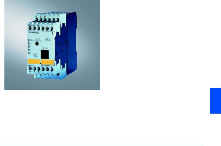
Safety monitor with enlarged functions |
||||||
|
Logical OR operation |
||||||
|
In this logical operation up to six elements can be OR gated. |
||||||
|
(Until now, only two elements could be OR gated). |
||||||
|
Logical AND operation |
||||||
|
In addition to the standard AND gating in the main path of an |
||||||
|
enabling circuit, an AND operation can be inserted into an OR |
||||||
|
operation. More than two elements can be gated in this AND. |
||||||
|
Buffer |
||||||
|
Temporary shutdowns are stored in a buffer for the purpose of |
||||||
|
diagnostics. |
||||||
|
Number of devices |
||||||
|
The number of devices that the safety monitor can process has |
||||||
|
been increased from 32 to 48. Applications that are larger and |
||||||
|
more complex can now be simulated in the safety monitor. |
||||||
|
Timer functions |
||||||
|
Timers are offered with the functions |
||||||
|
• Delayed switching-on |
||||||
|
The safety monitor is the core component of Safety at Work. A |
• Delayed switching-off and |
|||||
|
• Pulse. |
||||||
|
safe application is configured with a PC via the safety monitor. |
6 |
|||||
|
Compatibility |
||||||
|
Various different application-specific operating modes can be |
||||||
|
used. These include the EMERGENCY-STOP function, tumbler, |
Any configurations that have been previously created can be |
|||||
|
two-handed operation as well as selection of Stop category |
|
0 or 1. |
loaded into the «new» safety monitor without changes. |
|
In order to fully utilize the AS-Interface diagnostic capability, the |
|
|
monitor can also be operated with AS-Interface addresses as an |
|
|
alternative. |
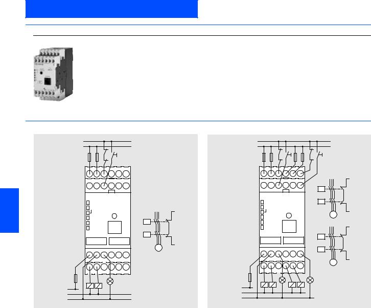
Two versions of the monitor are available:
•Safety monitor with one two-channel release circuit
•Safety monitor with two two-channel release circuits
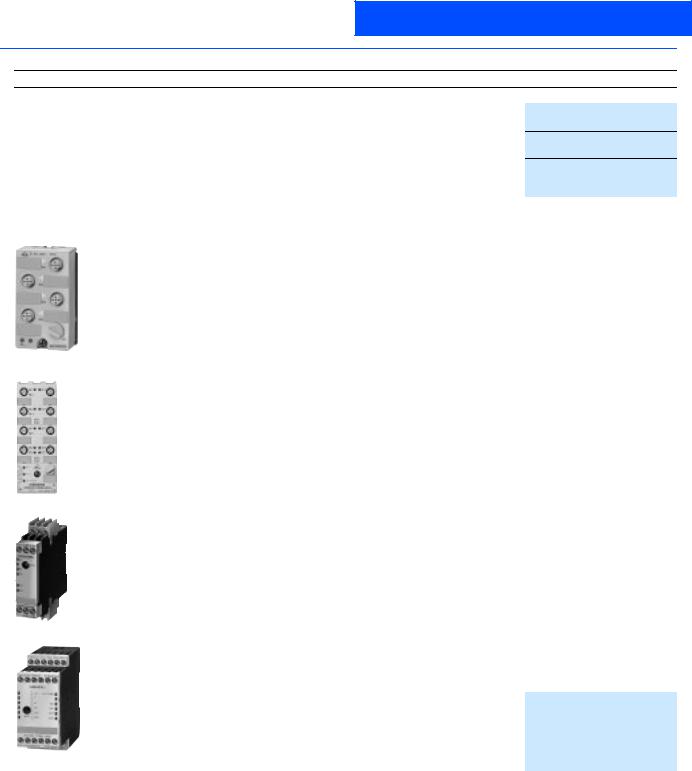
■Technical specifications
|
Safety monitor |
|||
|
3RK1 105 |
|||
|
Rated operational current |
|||
|
• Ie/AC-12 |
up to 250 V, 2 A |
||
|
• Ie/AC-15 |
115 |
V, 2A |
|
|
230 |
V, 2A |
||
|
• Ie/DC-12 |
up to 24 V, 3 A |
||
|
• Ie/DC-13 |
24 V, 1 A |
||
|
115 |
V, 0.1 A |
||
|
230 |
V, 0.05 A |
||
|
• Response time |
< 40 ms |
||
|
• Ambient temperature in °C |
0 to +60 |
||
|
• Storage temperature in °C |
-40 to +85 |
||
AS-Interface
AS-Interface Safety at work
AS-Interface safety monitors
■Selection and Ordering data
|
Design |
Order No. |
|
|
Safety monitor |
||
|
• One enabling circuit |
||
|
3RK1 105-1AE04-0CA0 |
||
|
• Two enabling circuits |
||
|
3RK1 105-1BE04-0CA0 |
||
|
Safety monitor with extended functionality |
||
|
• One enabling circuit |
||
|
3RK1105-1AE04-2CA0 |
||
|
• Two enabling circuits |
||
|
3RK1105-1BE04-2CA0 |
||
|
Configuration software |
3RK1 802-2FB06-0GA0 |
|
|
Safety monitor |
Cable set |
3RK1 901-5AA00 |
■Dimensional drawings
|
L/+ |
||
|
L |
||
|
K1 |
||
|
K2 |
Start 1 |
|
|
1.13 |
1.23 |
1.Y1 |
|
AS-i+AS-i- |
1.Y2 |
|
6 |
AS-i |
L+ |
|
1 |
||
|
2 |
K1 |
|
|
3 |
||
|
K2 |
||
|
1.Y1 |
||
|
M |
|
L+ |
M |
1.32 |
|
1.14 1.24 PE |
||
|
K1 |
K2 |
00356 |
|
L+ |
||
|
M/N |
xx |
|
|
M |
nsa0 |
|
|
g_ |
Safety monitor with one release circuit
|
L/+ |
|||||||
|
L |
|||||||
|
K1 |
Start 1 |
K3 |
Start 2 |
||||
|
K2 |
K4 |
||||||
|
1.13 |
1.23 |
1.Y1 |
|||||
|
AS-i+ AS-i- |
1.Y2 |
L/+ |
|||||
|
K1 |
|||||||
|
AS-i |
K2 |
1.Y1 |
|||||
|
M |
|||||||
|
1 |
|||||||
|
2 |
L/+ |
||||||
|
3 |
|||||||
|
K3 |
|||||||
|
K4 |
|||||||
|
L+ |
M |
1.32 |
2.32 |
M |
2.Y1 |
||
|
1.14 |
1.24 |
PE |
2.14 |
2.24 |
|||
|
K1 |
K2 |
K3 |
K4 |
L+
M/N
M
Safety monitor with two release circuits
g_nsa_xx_00357
|
6/10 |
Siemens IK PI · 2004 |
![]()
AS-Interface
AS-Interface Safety at work
AS-Interface safe compact modules
■Overview
The compact module product family will be supplemented with safe modules:
•The K45F safe compact module is equipped with two «safe» inputs. For operation up to category 2 acc. to EN 954-1, each input can be separately assigned. If category 4 is required, a two-channel input is available on the module.
•The K60F safe compact module has, in addition to the two safe inputs, also two standard outputs.
|
6 |
|||||||
|
■Technical specifications |
|||||||
|
K45F safe compact module |
K60F safe compact module |
K60F safe compact module |
|||||
|
PNP transistor |
PNP transistor |
PNP transistor |
|||||
|
Standard assignment |
Standard assignment |
Standard assignment |
|||||
|
2 safe inputs |
2 safe inputs, |
2 safe inputs, |
|||||
|
2 standard outputs |
2 standard outputs with UAux |
||||||
|
3RK1 205-0BQ00-0AA3 |
3RK1 405-0BQ00-0AA3 |
3RK1 405-0BQ00-0AA3 |
|||||
|
AS-Interface chip |
SAP 4 |
SAP 4 |
SAP 4 |
||||
|
Operational voltage |
26.5 to 31.5 |
26.5 to 31.5 |
26.5 to 31.5 |
||||
|
in accordance with AS-Interface |
|||||||
|
specification in V |
|||||||
|
Total current input in mA |
45 |
270 |
270 |
||||
|
Input connection |
PNP |
PNP |
PNP |
||||
|
Inputs |
|||||||
|
• Sensor supply via AS-Interface |
|||||||
|
— |
— |
— |
|||||
|
• Sensors |
|||||||
|
Mechanical switching contact |
Mechanical switching contact |
Mechanical switching contact |
|||||
|
• Voltage range in V |
|||||||
|
— |
— |
— |
|||||
|
• Current carrying capacity for all |
|||||||
|
— |
— |
— |
|||||
|
inputs (Tu 40 °C) in mA |
|||||||
|
• Switching level High in V |
|||||||
|
Contact open/closed |
Contact open/closed |
Contact open/closed |
|||||
|
• Input current Low/High in mA |
|||||||
|
— / /peak 5 |
— / /peak 5 |
— / /peak 5 |
|||||
|
Pin assignment inputs |
Pin1 and 2 = Terminal/switching |
Pin1 and 2 = Terminal/switching |
Pin1 and 2 = Terminal/switching |
||||
|
contact |
contact |
contact |
|||||
|
Pin3 and 4 |
Pin3 and 4 |
Pin3 and 4 |
|||||
|
Terminal/switching contact |
Terminal/switching contact |
Terminal/switching contact |
|||||
|
Pin5 = Not assigned |
Pin5 = Not assigned |
Pin5 = Not assigned |
|||||
|
Siemens IK PI · 2004 |
6/11 |

AS-Interface
AS-Interface Safety at work
AS-Interface safe compact modules
■Technical specifications (continued)
|
Outputs |
|||||
|
• Type of output |
|||||
|
— |
Electronics |
Electronics |
|||
|
• Current carrying capacity |
|||||
|
— |
2 |
— |
|||
|
DC 12/13 in A |
|||||
|
• Current carrying capacity typ. |
|||||
|
— |
Max. 0.18 |
Max. 4 |
|||
|
(max. 4 A per module) in A |
|||||
|
• Pin assignment outputs |
|||||
|
— |
3 = «–» |
3 = «–» |
|||
|
4 = Output |
4 = Output |
||||
|
5 = Earth connection |
5 = Earth connection |
||||
|
• Short-circuit protection |
|||||
|
— |
Built-in |
Built-in |
|||
|
• Inductive interference protec- |
|||||
|
— |
None |
Built-in |
|||
|
tion (free-wheeling diode) |
|||||
|
• External voltage supply |
|||||
|
— |
— |
Via black AS-Interface flat cable |
|||
|
24 V DC |
|||||
|
• Watchdog |
|||||
|
— |
Built-in |
Built-in |
|||
|
I/O configuration |
0 |
7 |
7 |
||
|
ID/ID2 code |
B |
B |
B |
||
|
Assignment of data bits |
|||||
|
• Socket 3 and 4 |
|||||
|
Not assigned (closed) |
Not assigned (closed) |
Not assigned (closed) |
|||
|
• Socket 5 |
|||||
|
Not assigned (closed) |
Pin 4 = OUT1 (D0) |
Pin 4 = OUT1 (D0) |
|||
|
Pin 2 = Not assigned (closed) |
Pin 2 = Not assigned (closed) |
||||
|
• Socket 6 |
|||||
|
Not assigned (closed) |
Pin 4 = OUT2 (D1) |
Pin 4 = OUT2 (D1) |
|||
|
• Socket 7 and 8 |
Pin 2 = Not assigned (closed) |
Pin 2 = Not assigned (closed) |
|||
|
Not assigned (closed) |
Not assigned (closed) |
Not assigned (closed) |
|||
|
6 |
AS-Interface certificate |
Yes |
Yes |
Yes |
|
|
Approvals |
UL, CSA |
UL, CSA |
UL, CSA |
||
|
Degree of protection |
IP67 |
IP67 |
IP67 |
||
|
Earth connection |
— |
PIN 5 of each M 12 socket is |
PIN 5 of each M 12 socket is |
||
|
connected to the grounding plate in |
connected to the grounding plate in |
||||
|
the mounting plate via a pin |
the mounting plate via a pin |
||||
|
(outputs only sockets 5 and 6). |
(outputs only sockets 5 and 6). |
||||
|
Ambient temperature in °C |
-25 to +85 |
-25 to +85 |
-25 to +85 |
||
|
Storage temperature in °C |
-40 to +85 |
-40 to +85 |
-40 to +85 |
||
|
Number of I/O sockets |
2 |
4 |
4 |
||
|
Status indication |
|||||
|
• I/O display |
|||||
|
Yellow LED |
Yellow LED |
Yellow LED |
|||
|
• UAux |
|||||
|
— |
— |
Green LED |
|||
|
• AS-Interface/diagnostics |
|||||
|
Green/red LED |
Green/red LED |
Green/red LED |
|||
|
display |
|||||
|
Connection |
via mounting plate for K45 compact |
via mounting plate for K60 compact |
via mounting plate for K60 compact |
||
|
module |
module |
module |
|||
|
Addressing |
Front addressing socket, |
Front addressing socket, |
Front addressing socket, |
||
|
after the 15th addressing, |
after the 15th addressing, |
after the 15th addressing, |
|||
|
the module keeps the last address |
the module keeps the last address |
the module keeps the last address |
|||
|
6/12 |
Siemens IK PI · 2004 |
|
AS-Interface |
||||
|
AS-Interface Safety at work |
||||
|
AS-Interface safe compact modules |
||||
|
■Selection and Ordering data |
||||
|
Design |
Order No. |
|||
|
K45F safe compact module 1) |
3RK1 205-0BQ00-0AA3 |
|||
|
2FE |
3RK1 205-0BQ00-0AA3
|
K45 mounting plate |
3RK1 901-2EA00 |
|
|
K60F safe compact module 1) |
||
|
• 2FE/2A |
||
|
3RK1 405-0BQ00-0AA3 |
||
|
• 2FE/2A with UAux |
||
|
3RK1 405-1BQ00-0AA3 |
||
|
K60 mounting plate |
3RK1 901-0CA00 |
|
|
Input bridge for K45/K60F |
||
|
• Black version |
||
|
3RK1 901-1AA00 |
||
|
• Red version |
||
|
3RK1 901-1AA01 |
||
|
3RK1 901-1AA00 |
||
AS-Interface M12 sealing caps, protected against manipulation
For spare M12 sockets
(one packing contains ten sealing caps)
3RK1 901-1KA01
1) Modules supplied without mounting plate.
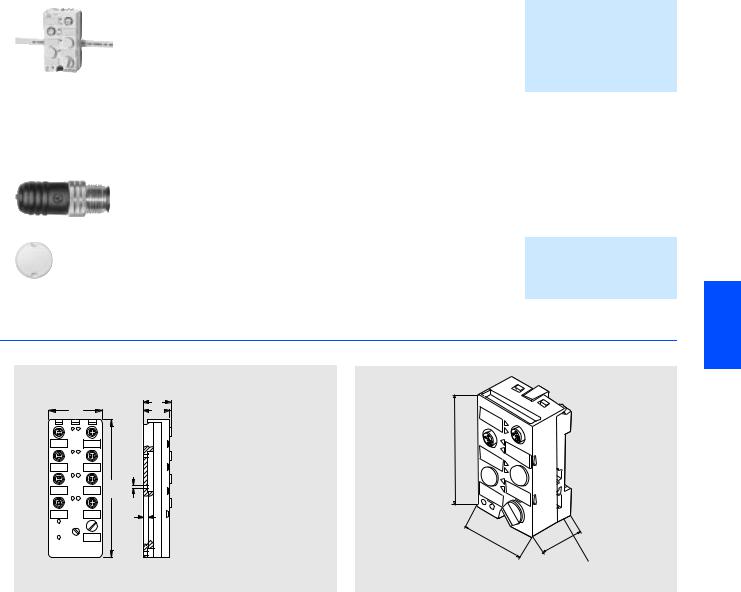
■Dimensional drawings
|
31 |
|
|
60 |
29 |
|
4,5 |
80 |
|
152 |
|
|
5 |
|
|
NSA000026 |
3RK1901-0CA00 |
|
Sideviewwith |
|
|
mountingplate |
45
3RK1 901-1KA01
6
30
Mounting plate 3RK1901-2EA00
|
K60F safe module |
K45F safe module |
|
Siemens IK PI · 2004 |
6/13 |
AS-Interface
AS-Interface Safety at work
AS-Interface safe compact modules
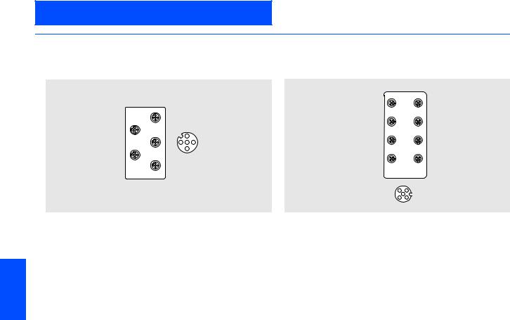
■Schematics
Logical assignments
K45F Safe Compact Module
|
1 |
||
|
2 |
2 |
|
|
3 |
1 |
3 |
|
4 |
4 |
|
|
ADDR |
G NSA0 XX 00355 |
|
|
Socket |
Assignment / data sheet / function |
|
|
1 |
Pin 1 and Pin 2: affects bits D0 and D1 = Channel 1 |
|
|
Pin 3 and Pin 4: affects bits D2 and D3 = Channel 2 |
||
|
Pin 5 not assigned |
||
|
2 |
Pin 1 and Pin 2: affects bits D2 and D3 = Channel 2 |
|
|
Pin 5 not assigned |
||
|
6 |
3 |
Unused |
|
4 |
Unused |
|
If only one single-channel switch will be connected to the module, this must be connected to Channel 1. The second channel must be bridged. This can be performed with the M12 connector 3RK1901-1AA00 on Socket 2.
Pin 3 of Socket 1 is connected to Pin 1 of Socket 2 and Pin 4 of Socket 1 is connected to Pin 2 of Socket 2. If both socket pairs are assigned, the inputs are linked.
K60F Safe Compact Module
12
34
56
78
41
3 2 NSA_00358
|
Socket |
Assignment / data sheet / function |
|
1 |
Pin1 and Pin 2: affects bits D0 and D1 = Channel 1 |
|
Pin 3 and Pin 4: affects bits D2 and D3 = Channel 2 |
|
|
Pin 5: unused |
|
|
2 |
Pin 1 and Pin 2: affects bits D2 and D3 = Channel 2 |
|
Pin 5: unused |
|
|
3/4/7 and |
Not assigned, factory sealed |
|
8 |
|
|
5 |
Pin 4: Output 1 |
|
Pin 3: — |
|
|
Pin 5: Ground |
|
|
Pin 1 and Pin 2: unused |
|
|
6 |
Pin 4: Output 2 |
|
Pin 3: — |
|
|
Pin 5: Ground |
|
|
Pin 1 and Pin 2: unused |
|
Pin 3 of Socket 1 is connected to Pin 1 of Socket 2 and Pin 4 of Socket 1 is connected to Pin 2 of Socket 2. If both socket pairs are assigned, the inputs are linked.
|
6/14 |
Siemens IK PI · 2004 |
AS-Interface
AS-Interface Safety at work
AS-Interface position switches
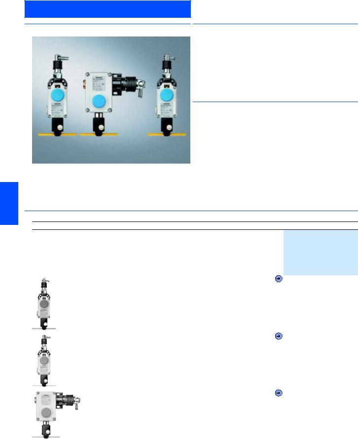
|
■Overview |
■Application |
|
|
Position switch with separate actuator |
||
|
The position switches with separate actuator are used in appli- |
||
|
cations in which the position of doors, covers or guards has to |
||
|
be monitored for safety reasons. |
||
|
The position switch can only be switched using the associated |
||
|
coded actuator. It is not possible to bypass it manually or using |
||
|
a tool. |
||
|
Position switch with tumbler |
||
|
The position switches with tumblers are special safety devices |
||
|
that prevent the inadvertent or intentional opening of protective |
||
|
doors, guards or other covers when a dangerous state exists, |
||
|
e.g. for coastdown movements of the switched-off machine. |
The safety switch with tumbler has two main tasks:
•Enabling the machine when the protective device is closed and locked
•Disabling the machine when the protective device is open
The position switch can only be switched using the associated coded actuator. It is not possible to bypass it manually or using a tool.
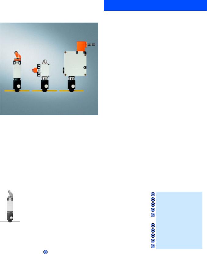
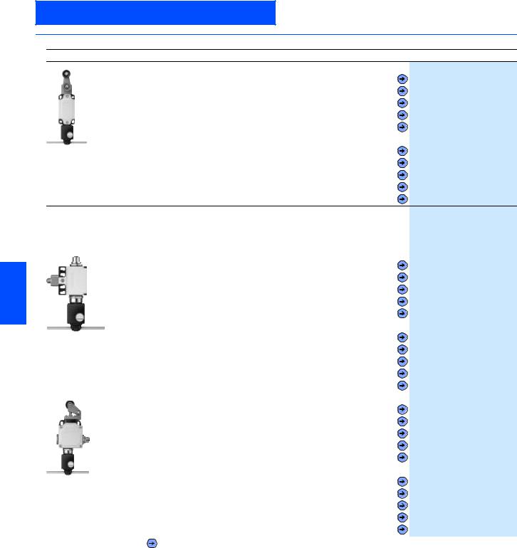
|
Position switch from left to right: |
|||||
|
Standard / Standard, with M12 connector / with tumbler |
6 |
||||
|
It is also possible now to directly connect SIGUARD position |
|||||
|
switches via the standard AS-Interface with safety-oriented com- |
|||||
|
munication. In this case, the safety functions no longer have to |
|||||
|
be conventionally wired up. |
|||||
|
Position switches convert the mechanical positions of moving |
|||||
|
machine components into electrical signals. |
|||||
|
■Selection and Ordering data |
|||||
|
Design |
Order No. |
||||
|
AS-Interface position switch, standard |
|||||
|
Via AS-Interface F adaptor |
|||||
|
With direct connection of AS-Interface to Safety at Work |
|||||
|
For use up to Category 2 acc. to EN 954-1 |
|||||
|
IP65 |
|||||
|
• Molded plastic enclosure, EN 50 047, 31 mm wide, slow-action contact, two NC |
|||||
|
— Overtravel plunger |
3SF3 200-6CV00-0BA1 |
|
|
— Roller plunger |
3SF3 200-6DV00-0BA1 |
|
|
— Roller lever |
3SF3 200-6EV00-0BA1 |
|
|
— Angular roller lever |
3SF3 200-6FV00-0BA1 |
|
|
— Swivel lever |
3SF3 200-6GV00-0BA1 |
|
|
• Molded plastic enclosure, EN 50 047, 31 mm wide, snap action contact, one NC |
||
|
3SF3 200-6EV00-0BA1 |
— Overtravel plunger |
3SF3 200-1CV00-0BA1 |
|
— Roller plunger |
3SF3 200-1DV00-0BA1 |
|
|
— Roller lever |
3SF3 200-1EV00-0BA1 |
|
|
— Angular roller lever |
3SF3 200-1FV00-0BA1 |
|
|
— Swivel lever |
3SF3 200-1GV00-0BA1 |
|
|
Forced opening IEC 60 947-5-1, Appendix K. |
|
Siemens IK PI · 2004 |
6/15 |
AS-Interface
AS-Interface Safety at work
AS-Interface position switches
■Selection and Ordering data (continued)
|
Design |
Order No. |
|
|
• Metal enclosure, EN 50 041, 40 mm wide, slow-action contact, two NC |
||
|
— Overtravel plunger |
3SF3 120-6CV00-0BA1 |
|
|
— Roller plunger |
3SF3 120-6DV00-0BA1 |
|
|
— Roller lever |
3SF3 120-6EV00-0BA1 |
|
|
— Angular roller lever |
3SF3 120-6FV00-0BA1 |
|
|
— Swivel lever |
3SF3 120-6GW00-0BA1 |
|
|
• Metal enclosure, EN 50 041, 40 mm wide, snap action contact, one NC |
||
|
3SF3 120-6GW00-0BA1 |
— Overtravel plunger |
3SF3 120-1CV00-0BA1 |
|
— Roller plunger |
3SF3 120-1DV00-0BA1 |
|
|
— Roller lever |
3SF3 120-1EV00-0BA1 |
|
|
— Angular roller lever |
3SF3 120-1FV00-0BA1 |
|
|
— Swivel lever |
3SF3 120-1GW00-0BA1 |
|
|
AS-Interface position switch, standard, with M12 connector |
||
|
M12 connector for connecting an additional position switch |
||
|
Direct connection of AS-Interface to Safety at Work |
||
|
For use up to Category 4 acc. to EN 954-1 |
||
|
IP65 |
||
|
• Molded plastic enclosure, EN 50 047, 50 mm wide, slow-action contact, 1 NC |
||
|
— Overtravel plunger |
3SF3 210-0CV00-0BA2 |
|
|
— Roller plunger |
3SF3 210-0DV00-0BA2 |
|
|
6 |
— Roller lever |
3SF3 210-0EV00-0BA2 |
|
— Angular roller lever |
3SF3 210-0FV00-0BA2 |
|
|
— Swivel lever |
3SF3 210-0GV00-0BA2 |
|
|
• Molded plastic enclosure, EN 50 047, 50 mm wide, snap-action contact, 1 NC |
||
|
3SF3 210-0DV00-0BA2 |
— Overtravel plunger |
3SF3 210-1CV00-0BA2 |
|
— Roller plunger |
3SF3 210-1DV00-0BA2 |
|
|
— Roller lever |
3SF3 210-1EV00-0BA2 |
|
|
— Angular roller lever |
3SF3 210-1FV00-0BA2 |
|
|
— Swivel lever |
3SF3 210-1GV00-0BA2 |
|
|
• Metal enclosure, EN 50 041, 56 mm wide, slow-action contact, 1 NC |
||
|
— Overtravel plunger |
3SF3 100-0CV00-0BA2 |
|
|
— Roller plunger |
3SF3 100-0DV00-0BA2 |
|
|
— Roller lever |
3SF3 100-0EV00-0BA2 |
|
|
— Angular roller lever |
3SF3 100-0FV00-0BA2 |
|
|
— Swivel lever |
3SF3 100-0GW00-0BA2 |
|
|
• Metal enclosure, EN 50 041, 56 mm wide, snap-action contact, 1 NC |
||
|
3SF3 100-0EV00-0BA2 |
— Overtravel plunger |
3SF3 100-1CV00-0BA2 |
|
— Roller plunger |
3SF3 100-1DV00-0BA2 |
|
|
— Roller lever |
3SF3 100-1EV00-0BA2 |
|
|
— Angular roller lever |
3SF3 100-1FV00-0BA2 |
|
|
— Swivel lever |
3SF3 100-1GW00-0BA2 |
|
|
Forced opening IEC 60 947-5-1, Appendix K. |
|
6/16 |
Siemens IK PI · 2004 |
|
AS-Interface |
||||||||||
|
AS-Interface Safety at work |
||||||||||
|
AS-Interface position switches |
||||||||||
|
■Selection and Ordering data (continued) |
||||||||||
|
Design |
Order No. |
|||||||||
|
AS-Interface position switch, with separate actuator |
||||||||||
|
With direct connection of AS-Interface to Safety at Work |
||||||||||
|
For use up to Category 2 acc. to EN 954-1 |
||||||||||
|
IP65, Slow-action contact, 2 NC |
||||||||||
|
• Molded plastic enclosure, side operation, fixing acc. to EN 50 047 |
||||||||||
|
3SF3 200-6XX03-0BA1 |
||||||||||
|
• Molded plastic enclosure, front operation, fixing acc. to EN 50 047 |
||||||||||
|
3SF3 200-6XX04-0BA1 |
||||||||||
|
• Molded plastic enclosure, side and front operation, 52 mm wide |
||||||||||
|
— 30 N extraction force |
||||||||||
|
3SF3 243-0XX00-0BA1 |
||||||||||
|
— 5 N extraction force |
||||||||||
|
3SF3 243-0XX40-0BA1 |
||||||||||
|
— Automatic ejection |
||||||||||
|
3SF3 243-0XX30-0BA1 |
||||||||||
|
• Metal enclosure, fixing acc. to EN 50 041 |
||||||||||
|
3SF3 120-6XX00-0BA1 |
||||||||||
|
Actuator |
||||||||||
|
• Standard, Width/length of enclosure |
79 mm |
|||||||||
|
3SX3 197 |
||||||||||
|
• With crosswise fixing, Width/length of enclosure |
50 mm |
|||||||||
|
3SX3 206 |
||||||||||
|
• Universal radius, Width/length of enclosure |
80 mm |
|||||||||
|
3SX3 203 |
||||||||||
|
AS-Interface position switch with separate actuator and M12 connector |
||||||||||
|
M12 connector for connecting an additional position switch |
||||||||||
|
Direct connection of AS-Interface to Safety at Work |
||||||||||
|
For use up to Category 4 acc. to EN 954-1 |
||||||||||
|
IP65, Slow-action contact, one NC |
||||||||||
|
Molded plastic enclosure |
||||||||||
|
Side and front operation |
6 |
|||||||||
|
52 mm wide |
||||||||||
|
• 30 N extraction force |
||||||||||
|
3SF3 257-6XX00-0BA2 |
||||||||||
|
• 5 N extraction force |
||||||||||
|
3SF3 257-6XX00-0BA2 |
3SF3 257-6XX40-0BA2 |
|||||||||
|
• Automatic ejection |
||||||||||
|
3SF3 257-6XX30-0BA2 |
||||||||||
|
Actuator |
||||||||||
|
• Standard, Width/length of enclosure |
27 mm |
|||||||||
|
3SX3 218 |
||||||||||
|
(rmin = 150 mm) |
||||||||||
|
• Universal radius, Width/length of enclosure |
33 mm |
3SX3 228 |
||||||||
|
(rmin = 45 mm) |
3SF3 750-6XX00-0BA1
3SF3 830-6XX00-0BA1
AS-Interface position switch, with separate actuator and tumbler
With direct connection of AS-Interface to Safety at Work
For use up to Category 4 acc. to EN 954-1
IP65, Pg 13.5, Solenoid voltage 24 V DC
Monitoring of actuator and solenoid position
|
• Plastic housing |
||
|
— Locking force 1200 N, locked by spring force |
3SF3 760-6XX00-0BA1 |
|
|
— Locking force 1200 N, locked by magnetic force |
3SF3 750-6XX00-0BA1 |
|
|
Actuator |
||
|
• Standard, |
3SX3 252 |
|
|
• with crosswise fixing |
3SX3 253 |
|
|
• radius |
3SX3 254 |
|
|
• Metal housing |
||
|
— Locking force 1200 N, locked by spring force |
3SF3 860-6XX00-0BA1 |
|
|
— Locking force 1200 N, locked by magnetic force |
3SF3 850-6XX00-0BA1 |
|
|
— Locking force 2000 N, locked by spring force |
3SF3 840-6XX00-0BA1 |
|
|
— Locking force 2000 N, locked by magnetic force |
3SF3 830-6XX00-0BA1 |
|
|
Actuator |
||
|
• Standard, length |
79 mm |
3SX3 197 |
|
— for left approach direction, length |
132 mm |
3SX3 207 |
|
— with crosswise fixing, length |
50 mm |
3SX3 206 |
|
• Universal radius, length |
80 mm |
3SX3 203 |
|
Forced opening IEC 60 947-5-1, Appendix K. |
1)1) Accessories, technical data, contact travel, circuit diagrams and dimensional drawings for the specified basic switch can be found in the Catalog LV 10, Edition 2004, Section AS-Interface Safety Systems.
|
Siemens IK PI · 2004 |
6/17 |
AS-Interface
AS-Interface Safety at work
AS-Interface cable-operated switches
■Overview ■Application
SIGUARD cable-operated switches are used for monitoring or for EMERGENCY-STOP facilities on particulary endangered system sections.
As the effective range of a cable-operated switch is limited by the length of the cord, large systems can also be protected.
Specifications
Switches with latching for implementation in EMERGENCY-STOP equipment correspond to the EN 418 standard.
■Function
The safety contacts of the AS-Interface cable-operated switch are positively driven.
The AS-Interface cable-operated switches are ready to operate after pretensioning of the pull-wire or the rope.
When the rope is pretensioned, it must be released before the cable-operated switch can be returned to the original state.
It is also possible to connect AS-Interface cable-operated switches via the standard AS-Interface with safety-oriented communication.
In this case, the safety functions no longer have to be conven-
6tionally wired up.
■Selection and Ordering data
AS-Interface cable-operated switch
With direct connection of AS-Interface to Safety at Work Metal housing with dust protection
Implementable up to Category 4 to EN 954-1 IP65
Latching to EN 418 Pushbutton release 2 NC contacts
|
• For cable lengths up to 10 m, |
3SF2 120-1BF00-0BA1 |
|
with adjustment window |
|
|
• For cable lengths up to 25 m, |
3SF2 150-1BF00-0BA1 |
|
with adjustment window |
|
|
• For cable lengths up to 50 m |
3SF2 140-1BF00-0BA1 |
 Forced opening IEC 60 947-5-1, Appendix K.
1)Accessories, technical specifications, contact travel, circuit diagrams and dimensional drawings are given for the specified basic switch in Catalog LV 10 Section AS-Interface Safety Systems
|
6/18 |
Siemens IK PI · 2004 |

AS-Interface
AS-Interface Safety at work
AS-Interface light curtains and light arrays for Category 4
|
■Overview |
■Benefits |
|
|
• Double-scan function |
||
|
• Cascading of host and guest devices |
||
|
• Two transmission channels |
||
|
■Design |
||
|
A SIGUARD Light Curtain or light array comprises a transmitter |
||
|
and a receiver that must be mounted opposite each other. |
||
|
Depending on the resolution and length, a specific number of |
||
|
transmit and receive diodes are arranged in a vertical row. |
||
|
The infra-red LEDs of the transmitter send short light pulses that |
||
|
are received by the receive diodes. |
||
|
SIGUARD Light Curtains: |
||
|
• Resolution 14, 30 and 50 mm, |
||
|
• Length 150 mm to 3 m, |
||
|
• Cascading of master and slave devices to create larger height |
||
|
or length of protective zone or for angular arrangement. |
||
|
SIGUARD Light Arrays: |
||
|
• 2-, 3- or 4-beam for access protection. |
The light curtains and light arrays of Category 4 acc. to EN 954- 1 offer active optical protection for persons at machines. They can be connected to AS-Interface directly and safely as an option.
SIGUARD light curtains and light arrays are
•active opto-electronic protective devices (AOPD),
•comply with Type 4 acc. to EN 61496-1, -2,
•are EU prototype-tested,
•protect the operating personel working on or near dangerous machines,
•operate contact-free,
•are free of wear in comparison to mechanical systems (e.g. safety mats).
For further details, see the manual «Safety Integrated“ and the operating instructions for the respective devices.
Standards
•EN 61 496-1, -2, IEC 61 496-1, -2 (requirements for non-contact protection systems)
•EN 999 (incl. calculation of safety clearances)
|
• EN 954-1 (safety of machines, safety-related parts of controls). |
6 |
|
Siemens IK PI · 2004 |
6/19 |

AS-Interface
AS-Interface Safety at work
AS-Interface light curtains and light arrays for Category 4
■Technical specifications
|
Technical specifications common to all AS-Interface light curtains and light arrays |
||||
|
Safety classification |
Type 4 according to IEC 61496-1, -2 or EN 61496-1 (self-monitoring) |
|||
|
Height of protective zone in mm |
150 to 1800 (for series with 14 and 30 mm resolution) |
|||
|
450 to 3000 (for series with 50 mm resolution) |
||||
|
750 to 3000 (for series with 90 mm resolution) |
||||
|
Width of protective zone, |
0.3 to 6 (for series with 14 mm resolution) |
|||
|
sensing range in m |
0.8 to 18 (for series with 30, 50 and 90 mm resolution as well as for light arrays) |
|||
|
0.6 to 60 (for light arrays) |
||||
|
Detection capability |
14 mm, 30 mm, 50 mm or 90 mm or complete persons with 2, 3 or 4 beams |
|||
|
Response time of the |
12 to 44, d-scan 15 to 83 (for 14 mm resolution) |
|||
|
safety equipment in ms 1) |
12 to 25, d-scan 15 to 44 (for 30 mm resolution) |
|||
|
< 22, d-scan 38 (for 50 mm resolution) |
||||
|
< 18, d-scan 25 (for 90 mm resolution) |
||||
|
Response time of the |
Response time 3SF7842 + response time of AS-Interface safety monitor (max. 40 ms) |
|||
|
complete system |
||||
|
Degree of protection |
IP65 |
|||
|
Supply current in mA |
Max. 130 (transmitter) |
|||
|
Max 140 (receiver) |
||||
|
Operating mode |
Protection mode without restart lockout |
|||
|
Transmitter/receiver synchronization |
Optical synchronization, two transmission channels can be selected |
|||
|
Infra-red disturbance suppression |
Two techniques for selection: |
|||
|
Standard = high suppression |
||||
|
d-scan = extremely high degree of suppression |
||||
|
6 |
Cross-section in mm |
55 * 52 |
||
|
Length in mm |
234 to 3084 (depending on height of protective zone) |
|||
|
Air humidity in % |
15 to 95 |
|||
|
Operating temperature in °C |
0 to +55 |
|||
|
Storage temperature in °C |
-25 to +70 |
|||
|
Supply voltage in V |
26.5 to 31.6 (according to AS-Interface specification) |
|||
|
ID-code receiver |
B |
|||
|
I/O-code receiver |
0 (four data bits as outputs) |
|||
|
Slave address receiver |
Active bus component, programmed by the user in the range 1 to 31 |
|||
|
(delivery status = bus address 0), supply voltage from the AS-Interface network |
||||
|
Slave address transmitter |
Passive bus component (no bus address), supply voltage from the AS-Interface network |
|||
|
Cycle time in ms |
5 (according to AS-Interface specification) |
|||
|
AS-Interface profile |
Safe slave |
|||
|
Electrical connection |
M 12 plug: |
|||
|
Pin 1 = ASI+ |
||||
|
Pin 3 = ASI- |
||||
1) From interruption of the protective zone to the cut-out command on AS-Interface
|
6/20 |
Siemens IK PI · 2004 |
![]()
AS-Interface
AS-Interface Safety at work
AS-Interface light curtains and light arrays for Category 4
■Selection and Ordering data
|
Design |
Order No. |
|||
|
SIGUARD Standard Light Curtain, 14 mm resolution |
||||
|
Type 4 acc. to IEC 61 496-1, -2 |
||||
|
Height of light curtain in mm |
Function |
|||
|
150 |
Transmitter |
|||
|
3SF7 842-6BB00 |
||||
|
150 |
Receiver |
|||
|
3SF7 842-6BB01 |
||||
|
225 |
Transmitter |
|||
|
3SF7 842-6BC00 |
||||
|
225 |
Receiver |
|||
|
3SF7 842-6BC01 |
||||
|
300 |
Transmitter |
|||
|
3SF7 842-6BD00 |
||||
|
300 |
Receiver |
|||
|
3SF7 842-6BD01 |
||||
|
450 |
Transmitter |
|||
|
3SF7 842-6BE00 |
||||
|
450 |
Receiver |
|||
|
3SF7 842-6BE01 |
||||
|
600 |
Transmitter |
|||
|
3SF7 842-6BF00 |
||||
|
600 |
Receiver |
|||
|
3SF7 842-6BF01 |
||||
|
750 |
Transmitter |
|||
|
3SF7 842-6BG00 |
||||
|
750 |
Receiver |
|||
|
3SF7 842-6BG01 |
||||
|
900 |
Transmitter |
|||
|
3SF7 842-6BH00 |
||||
|
900 |
Receiver |
|||
|
3SF7 842-6BH01 |
||||
|
1050 |
Transmitter |
|||
|
3SF7 842-6BJ00 |
||||
|
1050 |
Receiver |
|||
|
3SF7 842-6BJ01 |
||||
|
1200 |
Transmitter |
3SF7 842-6BK00 |
||
|
1200 |
Receiver |
|||
|
3SF7 842-6BK01 |
6 |
|||
|
1350 |
Transmitter |
|||
|
3SF7 842-6BL00 |
||||
|
1350 |
Receiver |
|||
|
3SF7 842-6BL01 |
||||
|
1500 |
Transmitter |
|||
|
3SF7 842-6BM00 |
||||
|
1500 |
Receiver |
|||
|
3SF7 842-6BM01 |
||||
|
1650 |
Transmitter |
|||
|
3SF7 842-6BN00 |
||||
|
1650 |
Receiver |
|||
|
3SF7 842-6BN01 |
||||
|
1800 |
Transmitter |
|||
|
3SF7 842-6BP00 |
||||
|
1800 |
Receiver |
|||
|
3SF7 842-6BP01 |
||||
|
SIGUARD Standard Light Curtain, 30 mm resolution |
||||
|
Type 4 acc. to IEC 61 496-1, -2 |
||||
|
150 |
Transmitter |
|||
|
3SF7 842-6DB00 |
||||
|
150 |
Receiver |
|||
|
3SF7 842-6DB01 |
||||
|
225 |
Transmitter |
|||
|
3SF7 842-6DC00 |
||||
|
225 |
Receiver |
|||
|
3SF7 842-6DC01 |
||||
|
300 |
Transmitter |
|||
|
3SF7 842-6DD00 |
||||
|
300 |
Receiver |
|||
|
3SF7 842-6DD01 |
||||
|
450 |
Transmitter |
|||
|
3SF7 842-6DE00 |
||||
|
450 |
Receiver |
|||
|
3SF7 842-6DE01 |
||||
|
600 |
Transmitter |
|||
|
3SF7 842-6DF00 |
||||
|
600 |
Receiver |
|||
|
3SF7 842-6DF01 |
||||
|
750 |
Transmitter |
|||
|
3SF7 842-6DG00 |
||||
|
750 |
Receiver |
|||
|
3SF7 842-6DG01 |
||||
|
900 |
Transmitter |
|||
|
3SF7 842-6DH00 |
||||
|
900 |
Receiver |
|||
|
3SF7 842-6DH01 |
||||
|
1050 |
Transmitter |
|||
|
3SF7 842-6DJ00 |
||||
|
1050 |
Receiver |
|||
|
3SF7 842-6DJ01 |
||||
|
1200 |
Transmitter |
|||
|
3SF7 842-6DK00 |
||||
|
1200 |
Receiver |
|||
|
3SF7 842-6DK01 |
||||
|
1350 |
Transmitter |
|||
|
3SF7 842-6DL00 |
||||
|
1350 |
Receiver |
|||
|
3SF7 842-6DL01 |
||||
|
1500 |
Transmitter |
|||
|
3SF7 842-6DM00 |
||||
|
1500 |
Receiver |
|||
|
3SF7 842-6DM01 |
||||
|
1650 |
Transmitter |
|||
|
3SF7 842-6DN00 |
||||
|
1650 |
Receiver |
|||
|
3SF7 842-6DN01 |
||||
|
1800 |
Transmitter |
|||
|
3SF7 842-6DP00 |
||||
|
1800 |
Receiver |
|||
|
3SF7 842-6DP01 |
||||
|
Siemens IK PI · 2004 |
6/21 |

AS-Interface
AS-Interface Safety at work
AS-Interface light curtains and light arrays for Category 4
■Selection and Ordering data (continued)
|
Design |
Order No. |
|||
|
SIGUARD Standard Light Curtain, 50 mm resolution |
||||
|
Type 4 acc. to IEC 61 496-1, -2 |
||||
|
Height of light curtain in mm |
Function |
|||
|
450 |
Transmitter |
|||
|
3SF7 842-6EE00 |
||||
|
450 |
Receiver |
|||
|
3SF7 842-6EE01 |
||||
|
600 |
Transmitter |
|||
|
3SF7 842-6EF00 |
||||
|
600 |
Receiver |
|||
|
3SF7 842-6EF01 |
||||
|
750 |
Transmitter |
|||
|
3SF7 842-6EG00 |
||||
|
750 |
Receiver |
|||
|
3SF7 842-6EG01 |
||||
|
900 |
Transmitter |
|||
|
3SF7 842-6EH00 |
||||
|
900 |
Receiver |
|||
|
3SF7 842-6EH01 |
||||
|
1050 |
Transmitter |
|||
|
3SF7 842-6EJ00 |
||||
|
1050 |
Receiver |
|||
|
3SF7 842-6EJ01 |
||||
|
1200 |
Transmitter |
|||
|
3SF7 842-6EK00 |
||||
|
1200 |
Receiver |
|||
|
3SF7 842-6EK01 |
||||
|
1350 |
Transmitter |
|||
|
3SF7 842-6EL00 |
||||
|
1350 |
Receiver |
|||
|
3SF7 842-6EL01 |
||||
|
1500 |
Transmitter |
|||
|
3SF7 842-6EM00 |
||||
|
1500 |
Receiver |
|||
|
3SF7 842-6EM01 |
||||
|
1650 |
Transmitter |
3SF7 842-6EN00 |
||
|
1650 |
Receiver |
|||
|
6 |
3SF7 842-6EN01 |
|||
|
1800 |
Transmitter |
|||
|
3SF7 842-6EP00 |
||||
|
1800 |
Receiver |
|||
|
3SF7 842-6EP01 |
||||
|
2100 |
Transmitter |
|||
|
3SF7 842-6ER00 |
||||
|
2100 |
Receiver |
|||
|
3SF7 842-6ER01 |
||||
|
2400 |
Transmitter |
|||
|
3SF7 842-6ES00 |
||||
|
2400 |
Receiver |
|||
|
3SF7 842-6ES01 |
||||
|
2700 |
Transmitter |
|||
|
3SF7 842-6ET00 |
||||
|
2700 |
Receiver |
|||
|
3SF7 842-6ET01 |
||||
|
3000 |
Transmitter |
|||
|
3SF7 842-6EU00 |
||||
|
3000 |
Receiver |
|||
|
3SF7 842-6EU01 |
||||
|
SIGUARD Standard Light Curtain, 90 mm resolution |
||||
|
Type 4 acc. to IEC 61 496-1, -2 |
||||
|
750 |
Transmitter |
|||
|
3SF7 842-6JG00 |
||||
|
750 |
Receiver |
|||
|
3SF7 842-6JG01 |
||||
|
900 |
Transmitter |
|||
|
3SF7 842-6JH00 |
||||
|
900 |
Receiver |
|||
|
3SF7 842-6JH01 |
||||
|
1050 |
Transmitter |
|||
|
3SF7 842-6JJ00 |
||||
|
1050 |
Receiver |
|||
|
3SF7 842-6JJ01 |
||||
|
1200 |
Transmitter |
|||
|
3SF7 842-6JK00 |
||||
|
1200 |
Receiver |
|||
|
3SF7 842-6JK01 |
||||
|
1350 |
Transmitter |
|||
|
3SF7 842-6JL00 |
||||
|
1350 |
Receiver |
|||
|
3SF7 842-6JL01 |
||||
|
1500 |
Transmitter |
|||
|
3SF7 842-6JM00 |
||||
|
1500 |
Receiver |
|||
|
3SF7 842-6JM01 |
||||
|
1650 |
Transmitter |
|||
|
3SF7 842-6JN00 |
||||
|
1650 |
Receiver |
|||
|
3SF7 842-6JN01 |
||||
|
1800 |
Transmitter |
|||
|
3SF7 842-6JP00 |
||||
|
1800 |
Receiver |
|||
|
3SF7 842-6JP01 |
||||
|
2100 |
Transmitter |
|||
|
3SF7 842-6JR00 |
||||
|
2100 |
Receiver |
|||
|
3SF7 842-6JR01 |
||||
|
2400 |
Transmitter |
|||
|
3SF7 842-6JS00 |
||||
|
2400 |
Receiver |
|||
|
3SF7 842-6JS01 |
||||
|
2700 |
Transmitter |
|||
|
3SF7 842-6JT00 |
||||
|
2700 |
Receiver |
|||
|
3SF7 842-6JT01 |
||||
|
3000 |
Transmitter |
|||
|
3SF7 842-6JU00 |
||||
|
3000 |
Receiver |
|||
|
3SF7 842-6JU01 |
||||
|
6/22 |
Siemens IK PI · 2004 |

AS-Interface
AS-Interface Safety at work
AS-Interface light curtains and light arrays for Category 4
■Selection and Ordering data (continued)
|
Design |
Order No. |
|
|
SIGUARD Light Array |
||
|
Type 4 acc. to IEC 61 496-1, -2 |
||
|
Sensing range in m |
Function |
|
|
18 |
Transmitter |
|
|
3SF7 842-6SE00 |
||
|
18 |
Receiver |
|
|
3SF7 842-6SE01 |
||
|
18 |
Transmitter |
|
|
3SF7 842-6PG00 |
||
|
18 |
Receiver |
|
|
3SF7 842-6PG01 |
||
|
18 |
Transmitter |
|
|
3SF7 842-6MH00 |
||
|
18 |
Receiver |
|
|
3SF7 842-6MH01 |
||
|
60 |
Transmitter |
|
|
3SF7 842-6SE50 |
||
|
60 |
Receiver |
|
|
3SF7 842-6SE51 |
||
|
60 |
Transmitter |
|
|
3SF7 842-6PG50 |
||
|
60 |
Receiver |
|
|
3SF7 842-6PG51 |
||
|
60 |
Transmitter |
|
|
3SF7 842-6MH50 |
||
|
60 |
Receiver |
|
|
3SF7 842-6MH51 |
||
6
|
Siemens IK PI · 2004 |
6/23 |
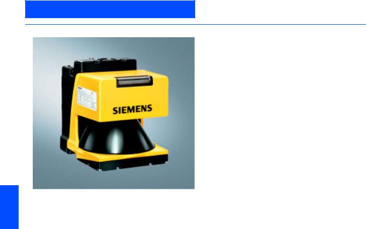
AS-Interface
AS-Interface Safety at work
AS-Interface laser scanner LS4
■Overview
The LS4 Laser Scanner is an optical distance sensor. The device periodically transmits light pulses within an operating range of 190°.
If the pulses hit an obstruction or a person, the light is reflected and then received and evaluated by the LS4 laser scanner. The scanner calculates the precise coordinates of the obstruction «seen» from the light propagation time.
If the obstruction or the person is located within defined ranges, a Stop function is executed. Switch-off is then performed via the safe interface within the system response time.
The Stop function is reset when the protective zone is free again, depending on the operating mode, either automatically or following acknowledgement.
Accessories
Accessories include a twistable mounting support, suitable preassembled connecting cables in diverse lengths as well as spare parts.
6
|
6/24 |
Siemens IK PI · 2004 |
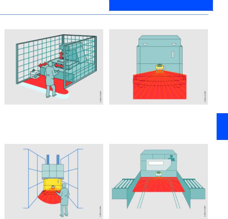
AS-Interface
AS-Interface Safety at work
AS-Interface laser scanner LS4
■Application
|
Horizontal danger zone protection |
Route monitoring for driverless transport systems |
Reliable detection of persons and objects in danger zones of machines and plants
Flexible configuration of any protection and warning zones to a great extent
Detection of persons and objects that approach the vehicle
The laser scanner offers a greater protection range than bumpers and therefore permits higher speeds.
6
|
Horizontal danger zone protection with several zones |
|
|
to be protected |
Collision protection for shifting units |
Safe detection of persons in various danger zones by switching over protection zones
Better availability when specifically securing only live zones
Protection of persons who are in the path of the vehicle
Objects in the path of the vehicle are detected early; damage to the vehicle or load is therefore prevented.
Further applications
•All types of hazardous area protection,
•Room protection and access protection,
•Projecting object monitoring (protection of machines and persons)
•Non-safety-related measurement or recognition tasks (e. g. distance, position or contour recognition)
|
Siemens IK PI · 2004 |
6/25 |
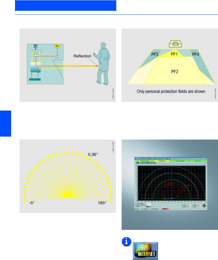
AS-Interface
AS-Interface Safety at work
AS-Interface laser scanner LS4
■Function
|
Function principle |
Protection and warning field pairs |
Bundled light pulses are created via a laser diode with coupled transmission optics. These are diverted by a rotating mirror in such a way that within 40 ms a light pulse is triggered in all angle segments (scan rate: 25 scans/s). If the light pulse hits an object or a person, the light is reflected and acquired and evaluated by
6the scanner.
Measuring pulse propagation time
The device has 4 switchable protection and warning field pairs.
LS4Soft operating software
The SIGUARD LS4 laser scanner must be parameterised using the associated LS4Soft software. The personal protection and warning fields required are set in this manner. Also configuration parameters, such as automatic/manual start, response time and restart time can be parameterised.
The SIGUARD LS4 laser scanner operates by measuring the pulse propagation time. When extremely short light pulses are emitted, a time difference occurs between the transmitted and received light pulse. The propagation time of the light pulse is a direct measurement of the target distance.
The operating range of the scanner (190°) is subdivided into angle segments of 0.36°.
Additional information is available in the Internet under:
http://www.siemens.de/laserscanner
|
6/26 |
Siemens IK PI · 2004 |

AS-Interface
AS-Interface Safety at work
AS-Interface laser scanner LS4
■Technical specifications
|
LS4-4 AS-Interface laser scanner |
3SF7 834-6DD00 |
|
Protective zone |
|
|
• Sensing range in m |
|
|
0 to 4 |
|
|
• Luminance factor in % |
|
|
Min. 1.8 |
|
|
• Object size (diameter) in mm |
|
|
70 (cylindrical test object) |
|
|
• Response time |
|
|
— Double evaluation (2 scans) |
|
|
85 |
|
|
in ms |
|
|
— Adjustable up to 16 scans in ms |
|
|
645 |
|
|
• Number |
|
|
4 (selectable via switch inputs) |
|
|
• Safety category |
|
|
Category 3 according to |
|
|
EN 954-1, Type 3 according to |
|
|
IEC 61496-1 or EN 61496-3 |
|
|
• Output |
|
|
Safe AS-Interface connection |
|
|
• Start-up |
|
|
Start-up testing and start-up |
|
|
disable can be set separately |
|
|
• Restart |
|
|
160 ms to 10 s |
|
|
(adjustable or manual) |
|
|
Protective zone supplement |
|
|
• For deactivated dust suppression |
|
|
81 |
|
|
in mm |
|
|
• For activated dust suppression |
|
|
in mm |
|
|
— For protective zone size |
|
|
81 |
|
|
< 3.5 mm |
|
|
— For protective zone size |
|
|
98 |
|
|
> 3.5 mm |
|
|
• Additional for reflectors in mm |
|
|
— Over 1.2 m behind the |
|
|
0 |
|
|
protective zone line |
|
|
— In the protective zone or up to |
|
|
110 |
|
|
1.2 m behind the protective |
|
|
zone line |
|
|
Warning zone |
|
|
• Sensing range in m |
|
|
0 to 15 |
|
|
• Luminance factor in % |
|
|
Min. 20 |
|
|
• Object size in mm |
|
|
150 150 |
|
|
• Response time in ms |
|
|
— Double evaluation (2 scans) |
|
|
85 |
|
|
— Adjustable up to 16 scans |
|
|
645 |
|
|
• Number of warning zones |
|
|
4 (selectable via switch inputs) |
|
|
• Output |
|
|
Connection of AS-Interface |
|
|
Contour measurement |
|
|
• Sensing range in m |
|
|
0 to 50 |
|
|
• Luminance factor in % |
|
|
Min. 20 |
|
|
• Output |
|
|
RS 232 serial interface |
|
|
via infra-red interface |
|
|
• Radial resolution in mm |
|
|
5 |
|
|
• Lateral resolution in ° |
|
|
0.36 |
|
|
Supply voltage |
|
|
• Via AS-Interface network in V |
|
|
29.5 to 31.6 (according to AS- |
|
|
Interface specification) |
|
|
• Via AS-Interface auxiliary voltage |
|
|
Up to DC 30 |
|
|
in V |
|
|
• Via external supply in V |
|
|
24 DC (+/-20 %) |
|
|
• Note |
|
|
The power supply unit for the |
|
|
external supply voltage as well as |
|
|
the AS-Interface power supply |
|
|
unit for supplying the AS-Inter- |
|
|
face components must feature |
|
|
safe mains isolation according to |
|
|
IEC 60742 and must bridge tem- |
|
|
porary mains failures of up to |
|
|
20 ms (e.g. AS-Interface power |
|
|
pack 3RX9 307-0AA00) |
|
|
Overcurrent protection |
1.25 A fuse, medium-slow |
|
Supply current in mA |
Typ. 350 |
|
LS4-4 AS-Interface laser scanner |
3SF7 834-6DD00 |
||
|
Inputs |
|||
|
• Restart/Reset |
|||
|
Connection of a command device |
|||
|
for «with restart lockout“ operating |
|||
|
mode and/or device resets, |
|||
|
dynamically monitored, |
|||
|
24 V DC opto-decoupled |
|||
|
• Zone-pair switchover |
|||
|
Selection of zone pairs via |
|||
|
4 control cables with internal |
|||
|
monitoring (one zone pair = |
|||
|
one protective zone and one |
|||
|
warning zone), |
|||
|
24 V DC opto-decoupled |
|||
|
• Signal definition in V |
|||
|
— High (logical 1) |
|||
|
16 to 30 |
|||
|
— Low (logical 0) |
|||
|
< 3 |
|||
|
• AS-Interface address |
|||
|
Connection of a generally |
|||
|
programming |
available AS-Interface address |
||
|
programmer |
|||
|
RS232 interfaces for each infrared |
For device parameterization and |
||
|
interface |
zone function |
||
|
Optical system |
|||
|
• Angular zone in ° |
|||
|
190 |
|||
|
• Angular resolution in ° |
|||
|
0.36 |
|||
|
• Lateral tolerance in ° |
|||
|
— Without mounting system (with |
|||
|
0.18 |
6 |
||
|
reference to the rear panel of the |
|||
|
housing) |
|||
|
— With mounting system (with ref- |
|||
|
0.22 |
|||
|
erence to the mounting surface) |
|||
|
• Scan rate |
|||
|
25 scans/s or 40 ms/scan |
|||
|
• Laser protection class |
|||
|
— According to standard |
|||
|
EN 60825-1, Class 1 |
|||
|
(safe for eyes) |
|||
|
— Wave length in nm |
|||
|
905 |
|||
|
— Beam divergence in mrad |
|||
|
2 |
|||
|
— Time base in s |
|||
|
100 |
|||
|
Degree of protection |
IP65 |
||
|
Ambient temperature in °C |
|||
|
• Operation |
|||
|
0 to +50 |
|||
|
• Storage |
|||
|
-20 to +60 |
|||
|
Housing insulation class |
Protection class 2 |
||
|
Humidity |
Acc. to DIN 40040, Table 10, |
||
|
Code Letter E (medium dry) |
|||
|
Dimensions (W x H x D) in mm |
140 168 165 |
||
|
Control cable X3 |
|||
|
• Length in m |
|||
|
Max. 50 (for cable cross-section |
|||
|
of 0.5 mm2, shielded) |
|||
|
• Note |
|||
|
Shield must be connected to PE |
|||
|
at the cabinet end only |
|||
|
Transmitter |
Infrared laser diode ( = 905 nm) |
||
|
Dimension spacing in mm |
|||
|
• Middle of the scan plane to |
|||
|
48,75 |
|||
|
bottom edge of housing |
|||
|
• Rear edge of housing to axis of |
|||
|
101 |
|||
|
rotating mirror |
|||
|
Housing |
|||
|
• LS4 |
|||
|
Cast aluminum, plastic |
|||
|
• AS-Interface rucksack |
|||
|
Plastic, steel connection plate |
|||
|
Vibration stress over three axes |
10 to 150 Hz, max. 5 g |
||
|
acc. to IEC 60068, Part 2-6 |
|||
|
Continuous shock over three axes |
10 g, 16 ms |
||
|
acc. to IEC 60068, Part 2-29 |
|||
|
Rotating mirror drive |
Brushless DC motor |
||
|
Rotating mirror bearings |
Maintenance-free ball bearings |
||
|
Siemens IK PI · 2004 |
6/27 |

AS-Interface
AS-Interface Safety at work
AS-Interface laser scanner LS4
■Technical specifications (continued)
|
LS4-4 AS-Interface laser scanner |
3SF7 834-6DD00 |
LS4-4 AS-Interface laser scanner |
3SF7 834-6DD00 |
|||||||||
|
AS-Interface |
Assignment |
PIN1 |
PIN2 |
PIN3 |
||||||||
|
• ID code |
||||||||||||
|
B |
• X1 (M12 plug for device |
|||||||||||
|
AS-i+ |
— |
AS-i- |
||||||||||
|
• I/O code |
connection) |
|||||||||||
|
0 (four data bits as outputs) |
||||||||||||
|
• Slave address |
• X2 (M12 connector for external |
|||||||||||
|
Programmed by the user in the |
24 V DC |
24 V Out |
Mass |
|||||||||
|
range 1 to 31 (delivery status = 0) |
power supply) |
supply |
||||||||||
|
• Cycle time according to |
• X3 (M12 socket for protective |
|||||||||||
|
5 |
SF pair 1 |
SF pair 2 |
SF pair 3 |
|||||||||
|
AS-Interface specification in ms |
zone changeover) |
|||||||||||
|
• Profiles |
• X4 (AS-Interface addressing |
|||||||||||
|
Safe slave |
AS-i+ |
AS-i- |
— |
|||||||||
|
• Electrical connection |
socket) |
|||||||||||
|
— X1 |
Assignment |
PIN 4 |
PIN 5 |
|||||||||
|
M 12 plug, AS-Interface |
||||||||||||
|
• X1 (M12 plug for device |
||||||||||||
|
— X2 |
M 12 plug, 24 V external |
– |
– |
|||||||||
|
connection) |
||||||||||||
|
Assignment of data bits D0 … D3 |
Protective zone empty: |
|||||||||||
|
• X2 (M12 connector for external |
||||||||||||
|
Start/ |
PE |
|||||||||||
|
Code sequence |
||||||||||||
|
power supply) |
Reset |
|||||||||||
|
Protective zone occupied: 0 |
||||||||||||
|
• X3 (M12 socket for protective |
||||||||||||
|
SF pair 4 |
24 V Out |
|||||||||||
|
Assignment of the diagnostic |
P0 = Alarm (according to LS4 |
|||||||||||
|
zone changeover) |
||||||||||||
|
parameter bits |
programming) |
|||||||||||
|
• X4 (AS-Interface addressing |
– |
– |
||||||||||
|
P1/2 = SF coding |
||||||||||||
|
socket) |
||||||||||||
|
(see assignment of SF coding) |
||||||||||||
|
P3 = LS4-RESET (via PC/AS- |
||||||||||||
|
Interface master call) |
||||||||||||
|
Assignment of SF coding |
P2 |
P1 |
SF |
|||||||||
|
0 |
0 |
1 |
||||||||||
|
0 |
1 |
2 |
||||||||||
|
1 |
0 |
3 |
||||||||||
|
6 |
1 |
1 |
4 |
|||||||||
|
■Selection and Ordering data |
||||||||||||
|
Design |
Order No. |
|||||||||||
|
AS-Interface LS4-4 laser scanner |
3SF7 834-6DD00 |
|||||||||||
|
Including LS4soft Software |
||||||||||||
Accessories
|
Mounting system |
3RG7 838-1AA |
|
Adapter plate |
3RG7 838-1AB |
|
PC cable connector |
3RG7 838-1DC |
|
Including plug, 9-pole and optical interface |
|
|
6/28 |
Siemens IK PI · 2004 |
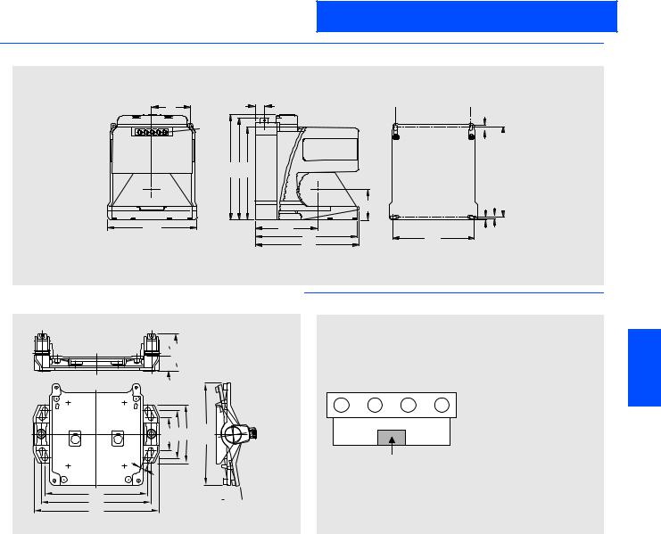
AS-Interface
AS-Interface Safety at work
AS-Interface laser scanner LS4
■Dimensional drawings
|
61 |
13,5 |
|
|
LED |
NSC0_00630 |
|
|
(5x) |
||
|
168 |
163 |
149 |
|
LS4 laser scanner |
■Schematics |
 122
122 5,2
5,2


|
9,5 |
|||||||
|
144 |
|||||||
|
5 |
5,2 |
||||||
9,5


129
23
 56,6
56,6
|
51,5 74,4 90 |
155,4 |
|
|
9 |
||
|
158 |
00610 |
|
|
166 |
NSC |
|
|
192 |
||
Assembly system
 9°
9°
NSC0_00631a
X1:M12connector,AS-Interface
X2 X3 X4 X1 X2:M12connector,
optionalauxiliaryvoltage
X3:M12socket,protectionfield
change-over
X4:Addressingsocket,AS-Interface
Opticalinterface
6
|
Siemens IK PI · 2004 |
6/29 |
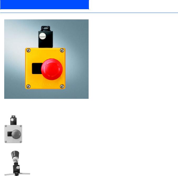
AS-Interface
AS-Interface Safety at work
AS-Interface EMERGENCY STOP pushbuttons
■Overview
It is also possible now to connect EMERGENCY STOP devices via the standard AS-Interface with safety-oriented communication. This only applies to EMERGENCY STOP devices of the SIGNUM 3SB3 command devices for front panel installation and for installation in an enclosure.
|
6 |
■ |
Selection and Ordering data |
||
|
Design |
Order No. |
|||
|
AS-Interface EMERGENCY STOP housing |
||||
|
Two NC contacts |
||||
|
AS-Interface F adaptor |
||||
|
• Yellow cover |
||||
|
3SF5 801-3AA08 |
||||
|
• Yellow cover with protective collar |
||||
|
3SF5 801-3AB08 |
||||
|
3SF5 801-3AA08 |
||||
|
AS-Interface EMERGENCY STOP front plate / |
3SF5 402-1AA01 |
|||
|
AS-Interface F adaptor |
||||
|
For AS-Interface EMERGENCY STOP |
||||
|
Front panel mounting |
||||
|
EMERGENCY STOP actuator is not included 1) |
||||
|
3SF5 402-1AA01 |
||||
|
Accessories |
||||
|
Safety Integrated manual |
||||
|
• German |
||||
|
E20001-A110-M103 |
||||
|
• English |
||||
|
E20001-A110-M103-X-7600 |
||||
1) See Catalog LV 10, Section Pushbuttons and Indicator Lamps
|
6/30 |
Siemens IK PI · 2004 |
![]()
AS-Interface Master
Masters for SIMATIC S5
CP 2430
■Overview
•Master connection for SIMATIC S5-115U to -155U
•Simple operation in the I/O address area of the SIMATIC S5-115U, -135U, -155U
•No need for CP configuration
•Two AS-Interface masters in one module
•Control of up to 2 x 31 AS-Interface slaves according to AS-Interface Specification V2.0
•Up to 496 binary elements can be controlled when using bidirectional slaves
•Monitoring of the supply voltage on the AS-Interface shaped cable
■Benefits
•Saving on slots and costs because two AS-Interface masters are located on one module
•Shorter startup times due to easy configuration at the press of a button
•Reduction of standstill or service times in the event of a fault through LED displays:
—status of the AS-Interface network
—connected slaves and their operational readiness
—monitoring of the ASInterface voltage level
■Application
Master connection for:
•SIMATIC S5-115U:
CP can be inserted at CP slots in the central controller and expansion unit
•SIMATIC S5-135/S5-155U:
For exclusive use of I/O mode can be plugged into the I/O slots in the central controller and expansion unit; in cache mode, CP can be inserted at CP slots in the central controller and expansion unit
•Up to four CP 2430s can be used in the PLC, depending on PLC configuration.
■Design
•Two AS-Interface masters in one module
•Occupies a slot in SIMATIC S5
•For operation in the S5-115U an adapter casing is required.
•In I/O mode 32 byte are used in the I/O address space
•Display of the connected and activated slaves and their operational readiness
•Connection of the two AS-Interface cables through connectors with terminal strip (solder-free connection with screw lock)
•One pushbutton per master unit for switching the operating status and entering the existing configuration
Each of the AS-Interface masters in the CP 2430 independently controls its own AS-Interface segment with up to 31 AS-Interface slaves. This allows control of a maximum of 2 x 31 AS-Interface slaves with a total of 248 binary sensors/actuators (496 when bidirectional slaves are used).
The front plate has separate status indicators for each master section, and a common LED matrix display for the active slaves.
The module address, page address and mode are set through encoding switches.
Two modes:
•Standard mode
Only the data bits of the slaves in the I/O address space of the PLC can be accessed in this operating mode. No master calls can be executed.
•Extended mode
Access to the master calls is provided through data handling blocks and the page interface in accordance with the AS-Inter- face Specification V2.0 (e.g. writing parameters).
User interface
There is a choice of three versions:
•I/O operation:
Only access to slave data in the I/O address space, no master calls
•I/O and page mode:
Access to slave data in the I/O address space and master calls through page access
•Page mode:
Access to slave data and master calls through page access
|
Siemens IK PI · 2004 |
6/31 |

AS-Interface Master
Masters for SIMATIC S5
CP 2430
■Technical specifications
|
Bus cycle time |
5 ms with 31 slaves |
|
|
AS-Interface Specification |
V 2.0 |
|
|
Interfaces |
||
|
• I/O address space used i |
||
|
32 byte in I/O operation |
||
|
n the PLC |
||
|
• AS-Interface connection |
||
|
2 x 4-pin socket for connector |
||
|
with terminal clamp |
||
|
Supply voltage |
+5 V DC through backplane bus |
|
|
Current consumption |
||
|
• Through backplane bus |
||
|
Typ. 700 mA at 5 V DC |
||
|
• From the AS-Interface shaped |
||
|
Max. 100 mA per AS-Interface |
||
|
cable |
segment |
|
|
Power loss |
7.9 W |
|
|
Perm. environmental conditions |
||
|
• Operating temperature |
||
|
0°C to +60°C |
||
|
• Transport/storage temperature |
||
|
-40 °C to +70 °C |
||
|
• Relative humidity max. |
||
|
95% at +25 °C |
||
|
Design |
||
|
• Module format |
||
|
Double-height Eurocard format |
||
|
• Dimensions (W x H x D) in mm |
||
|
160 x 233.4 x 20.32 |
||
|
• Weight |
||
|
400 g |
||
|
• Space required |
||
|
1 slot |
||
6
|
■ Ordering data |
Order No. |
|
|
CP 2430 |
6GK1 243-0SA20 |
|
|
communications processor |
||
For connecting
SIMATIC S5-115U, -135U, -155U to AS-Interface;
including connector
|
Manual for AS-Interface |
|
|
Including: |
|
|
CP 2413/CP 2430/CP2433 Manual, |
|
|
Introduction and Fundamentals; |
|
|
including software |
|
|
(FB60 and examples) |
|
|
• German |
|
|
6GK1 971-2SA01-0AA0 |
|
|
Electronic manuals |
6GK1 975-1AA00-3AA0 |
|
Communications systems, |
|
|
protocols, products |
|
|
on CD-ROM |
|
|
German/English |
|
|
6/32 |
Siemens IK PI · 2004 |

AS-Interface Master
Masters for SIMATIC S7
CP 142-2
|
■Overview |
■Design |
|
|
• 16 byte inputs and 16 byte outputs are used in the address |
||
|
space of the ET 200X |
||
|
• Operating statuses displayed by LEDs in the frontplate |
||
|
• Display of the connected and activated slaves and their oper- |
||
|
ational readiness by LEDs |
||
|
• One pushbutton for switching the operating status, entering the |
||
|
existing configuration and switching the display |
||
|
• Connection of the AS-Interface cable to M12 connector |
||
|
• Monitoring of the supply voltage on the AS-Interface cable |
||
|
■Function |
•Master connection for the distributed I/O system ET 200X at AS-Interface through 12-pin connector
•Simple operation in the I/O address area of SIMATIC ET 200X
•No need to configure CP for AS-Interface
•Addressing of up to 31 AS-Interface slaves according to the AS-Interface Specification V2.0
•Monitoring of the supply voltage on the AS-Interface shaped cable
•Considerable increase in the number of inputs/outputs of the ET 200X.
■Benefits
•In connection with the BM 147, the ET 200X enables PLC functionality in degree of protection IP65
•Can also be used in a rugged industrial environment without additional casing due to the high degree of protection IP67
•More flexible and extended application options of the ET 200X thanks to considerable increase in available inputs/outputs
•Shorter startup times due to easy configuration at the press of a button
•Reduction of standstill or service times in the event of a fault through LED displays:
—status of the AS-Interface network
—connected slaves and their operational readiness
—monitoring of the ASInterface voltage level
■Application
The CP 142-2 can be used in two operating modes:
•Standard mode with BM 141/BM 142/BM 147
•A maximum of all 124 input and output bits of the AS-Interface slaves can be addressed.
•Extended mode with BM 147
A function call facilitates master calls in accordance with the AS-Interface Specification V2.0 (e.g. writing parameters). Calls are described in the manual. The manual also contains program examples.
|
PROFIBUS |
||
|
ET 200X with CP 142-2 |
6 |
|
|
0 |
1 |
|
|
AS-Interface |
||
|
AS-Interface shaped cable |
G_IK10_XX_20013 |
|
System configuration
Parameter assignment
The CP 142-2 is parameterized with STEP® 7 basic package as of V2.1. Separate configuration for AS-Interface is not necessary.
The CP 142-2 enables the connection of the distributed I/O system ET 200X to AS-Interface.
This module can be used to activate up to 31 AS-Interface slaves and, if bi-directional slaves are implemented, up to 248 binary components.
Up to 6 CP 142-2 can be operated on the ET 200X.
|
Siemens IK PI · 2004 |
6/33 |

AS-Interface Master
Masters for SIMATIC S7
CP 142-2
■Technical specifications
|
Bus cycle time |
5 ms with 31 slaves |
|||
|
Configuration |
||||
|
• AS-Interface |
||||
|
Using pushbutton on front plate |
||||
|
• PROFIBUS |
||||
|
The CP 142-2 occupies 16 byte |
||||
|
inputs and 16 byte outputs in the |
||||
|
PROFIBUS configuration of the |
||||
|
ET 200X |
||||
|
AS-Interface Specification |
V 2.0 |
|||
|
• With BM 141/BM 142 |
||||
|
Only I/O transmission |
||||
|
• With BM 147 and FC, ASI-3422 |
||||
|
All functions |
||||
|
Connection of the AS-Interface |
Through M12 connector on the |
|||
|
cable |
front plate |
|||
|
Address range |
16 input bytes |
|||
|
16 output bytes |
||||
|
Supply voltage |
||||
|
• Through backplane bus |
||||
|
24 V DC |
||||
|
• From the AS-Interface shaped |
||||
|
According to the AS-Interface |
||||
|
cable |
Specification V2.0 |
|||
|
Power loss |
2 W |
|||
|
Current consumption |
||||
|
• Through backplane bus |
||||
|
Typ. 50 mA at 24 V DC |
||||
|
• Through AS-Interface from the |
||||
|
According to the AS-Interface |
||||
|
AS-Interface shaped cables |
specification V 2.0 |
|||
|
6 |
Perm. environmental conditions |
|||
|
• Operating temperature |
0°C to +55°C |
|||
|
• Transport/storage temperature |
||||
|
-40 °C to +70 °C |
||||
|
• Relative humidity |
||||
|
95% at +25 °C |
||||
|
Design |
ET 200X design |
|||
|
• Module format |
||||
|
Expansion module |
||||
|
• Dimensions (W x H x D) in mm |
||||
|
87 x 110 x 63 |
||||
|
• Weight |
||||
|
Approx. 310 g |
||||
|
• Space required |
||||
|
1 slot |
||||
|
Degree of protection |
IP66/67 |
|||
|
■Ordering data |
Order No. |
|
|
CP 142-2 |
6GK7 142-2AH00-0XA0 |
|
|
communications processor |
||
|
For connecting SIMATIC ET 200X |
||
|
to AS-Interface |
||
|
CP 142-2 manual |
6GK7 142-2AH00-8AA0 |
|
|
• German |
||
|
Electronic manuals |
6GK1 975-1AA00-3AA0 |
|
|
Communications systems, |
||
|
protocols, products |
||
|
on CD-ROM |
||
|
German/English |
||
|
6/34 |
Siemens IK PI · 2004 |

AS-Interface Master
Masters for SIMATIC S7
CP 243-2
The CP 243-2 is the AS-Interface master for the new generation of SIMATIC S7-200. The communications processor (6GK1 243- 2AX01-0AX0) supports the expanded AS-Interface specification V2.1 and has the following functions:
•Connection of up to 62 AS-Interface slaves and integrated analog value transmission (according to expanded AS-Interface Specification V2.1)
•Supports all AS-Interface master functions according to expanded AS-Interface Specification V2.1
•Display of operating status and operational readiness of the connected slaves through LEDs in the frontplate
•Display of errors (incl. AS-Interface voltage errors, configuration errors) through LEDs in the frontplate
•Compact housing in the design of the innovative SIMATIC S7-200 generation
The CP 243-2 is the AS-Interface master connection exclusively for the CPUs 22x of the innovated SIMATIC S7-200 generation. By connecting to AS-Interface, the available digital inputs and outputs for S7-200 are significantly increased (max. 248 DI / 186 DO on AS-Interface per CP).
In addition, the integrated analog value processing also makes analog values (per CP max. 31 analog slaves, each with up to 4 channels) available to the S7-200 at the AS-Interface. Up to two CP 243-2s can be operated simultaneously on the S7-200.
■Design
The CP 243-2 is connected to the S7-200 like an expansion module. It features:
•Two terminals for direct connection of the AS-Interface cable
•LEDs in the front panel for displaying the operating status and the operational readiness of all connected and activated slaves
•Two pushbuttons for displaying the status information of the slaves, for switching the operating status and entering the existing ACTUAL configuration as the SETPOINT configuration
■Function
The CP 243-2 supports all functions stipulated in the expanded AS-Interface Specification V2.1. Double address assignment 6 (A-B) makes it possible to operate up to 62 digital or 31 analog
slaves at the AS-Interface.
Access to analog values is just as easy as access to digital values, thanks to the integrated analog value processing.
The CP 243-2 occupies one digital input byte (status byte), one digital output byte (control byte) and 8 analog input and 8 analog output words in the process image of the S7-200. This means that the CP 243-2 occupies two slots. The operating mode of the CP 243-2 can be set with the status and control byte through the application program.
Depending on the operating mode, the CP 243-2 either stores the I/O data of the AS-Interface slaves or diagnostic values in the analog address space of the S7-200 or enables master calls (e.g. readdressing of slaves).
■Benefits
•More flexible and extended application options of the SIMATIC S7-200 due to the considerable increase in the available digital and analog inputs/outputs
•Shorter startup times due to easy configuration at the press of a button
•In the event of a fault, shorter standstill and service times due to LED indication of:
•Status of the CPs
—connected slaves and their operational readiness
—monitoring of the AS-Interface voltage level
All connected AS-Interface slaves are configured at the press of a button. No further configuration of the CP is necessary.
|
Siemens IK PI · 2004 |
6/35 |

AS-Interface Master
Masters for SIMATIC S7
CP 243-2
■Technical specifications
|
AS-Interface Specification |
V 2.1 |
|
|
Interfaces |
||
|
• Address space used in the PLC |
||
|
Corresponding to 2 I/O modules |
||
|
(8 DI/8 DO and 8 AI/8 AO) |
||
|
• AS-Interface connection |
||
|
Terminal |
||
|
Current consumption |
||
|
• Via AS-Interface |
||
|
Max. 100 mA |
||
|
• Through backplane bus |
||
|
Typ. 220 mA at 5 V DC |
||
|
Power loss |
Approx. 2 W |
|
|
Perm. environmental conditions |
||
|
• Operating temperature |
||
|
— Horizontal mounting |
||
|
0°C to +55°C |
||
|
— Vertical mounting |
||
|
0°C to +45°C |
||
|
• Transport/storage temperature |
||
|
-40 °C to +70 °C |
||
|
• Relative humidity |
||
|
Max. 95% at +25 °C |
||
|
Design |
||
|
• Module format |
||
|
S7-22x expansion module |
||
|
• Dimensions (W x H x D) in mm |
||
|
71.2 x 80 x 62 (H+16 mm with |
||
|
holes for wall mounting) |
||
|
• Weight |
||
|
Approx. 250 g |
||
|
• Space required |
||
|
1 slot |
||
6
|
■Ordering data |
Order No. |
|
|
CP 243-2 |
6GK7 243-2AX01-0XA0 |
|
|
communications processor |
||
For connection of SIMATIC S7-200 (2nd generation) to AS-Interface with bus connector
|
Manual for CP 243-2 |
|
|
Including AS-Interface |
|
|
fundamentals and diskette |
|
|
with program examples |
|
|
paper version |
|
|
• German |
|
|
6GK7 243-2AX00-8AA0 |
|
|
• English |
|
|
6GK7 243-2AX00-8BA0 |
|
|
• French |
|
|
6GK7 243-2AX00-8CA0 |
|
|
• Spanish |
|
|
6GK7 243-2AX00-8DA0 |
|
|
• Italian |
|
|
6GK7 243-2AX00-8EA0 |
|
|
6/36 |
Siemens IK PI · 2004 |

AS-Interface Master
Masters for SIMATIC S7
CP 343-2
The CP 343-2 is the AS-Interface master for PLC SIMATIC S7-300 and the distributed I/O device ET 200M. The communications processor offers the following functions:
•Connection of up to 62 AS-Interface slaves and integrated analog value transmission (according to expanded AS-Interface Specification V2.1)
•Supports all AS-Interface master functions according to expanded AS-Interface Specification V2.1
•Display of operating status and operational readiness of the connected slaves through LEDs in the frontplate
•Display of errors (incl. AS-Interface voltage errors, configuration errors) through LEDs in the frontplate
•Compact housing in the design of the SIMATIC S7-300
■Benefits
•Shorter startup times due to easy configuration at the press of a button
•Flexible decentralized topologies can be constructed by using this communications processor in the ET 200M DP slave.
•Reduction of standstill or service times in the event of a fault through LED displays:
—status of the AS-Interface network
—connected slaves and their operational readiness
—monitoring of the ASInterface voltage level
•Reduced costs for spare parts inventories because the CP can be used in both the SIMATIC S7-300 and in ET 200M.
•Ideal for complex applications through the connection option of 62 slaves and integrated analog value processing
The CP 343-2 is the AS-Interface master connection for SIMATIC S7-300 and ET 200M. Connection to the AS-Interface allows access to max. 248 DI/186 DO per CP.
The integrated analog value processing also supports evaluation of very simple analog signals (per CP at max. 31 analog slaves, each with four channels).
■Design
The CP 343-2 is connected to the S7-300 like an expansion module. It features:
•Two terminals for direct connection of the AS-Interface cable
•LEDs in the frontplate for displaying the operating status and the operational readiness of all connected and activated slaves
•Pushbuttons for displaying the status information of the slaves, for switching the operating status and entering the existing ACTUAL configuration as the SETPOINT configuration
■Function
|
The CP 343-2 supports all functions stipulated in the expanded |
||
|
AS-Interface Specification V2.1. Double address assignment (A- |
||
|
B) makes it possible to operate up to 62 digital or 31 analog |
||
|
slaves at the AS-Interface. Access to analog values is easy |
6 |
|
|
thanks to the integrated analog value processing. |
||
|
All connected AS-Interface slaves are configured at the press of |
||
|
a button. No further configuration of the CP is necessary. |
||
■Mode of operation
In I/O mode, the CP 343-2 reserves 16 bytes in the analog address space of the SIMATIC S7-300. The I/O data of the standard slaves or A slaves is stored here. The I/O data of the B slaves can be accessed using the «read/ write data record “ function.
A and B slaves are slaves in accordance with the extended AS-Interface specification V2.1. For the AS-Interface master calls (e.g. Write parameter, read diagnostic values), a Function Call (FC) is provided on the diskette that accompanies the manual.
|
Siemens IK PI · 2004 |
6/37 |

AS-Interface Master
Masters for SIMATIC S7
CP 343-2
■Technical specifications
|
AS-Interface Specification |
V 2.1 |
|
|
Bus cycle time |
5 ms for 31 slaves |
|
|
10 ms for 62 slaves |
||
|
Interfaces |
||
|
• Assignment of analog address |
||
|
16 byte I/O and P-bus S7-300 |
||
|
space in the PLC |
||
|
• AS-Interface connection |
||
|
S7-300 front connector |
||
|
with terminal |
||
|
Supply voltage |
+5 V DC through backplane bus |
|
|
Current consumption |
||
|
• through backplane bus |
||
|
Typ. 200 mA at 5 V DC |
||
|
• through AS-Interface from the |
||
|
Max. 100 mA |
||
|
AS-Interface shaped cables |
||
|
Power loss |
2 W |
|
|
Perm. environmental conditions |
||
|
• Operating temperature |
||
|
0°C to +60°C |
||
|
• Transport/storage temperature |
||
|
-40 °C to +70 °C |
||
|
• Relative humidity, max. |
||
|
95% at +25 °C |
||
|
Design |
||
|
• Module format |
||
|
S7-300 design |
||
|
• Dimensions (W x H x D) in mm |
||
|
40 x 125 x 120 |
||
|
• Weight |
||
|
Approx. 190 g |
||
|
• Space required |
1 slot |
6
|
■Ordering data |
Order No. |
|
|
CP 343-2 |
6GK7 343-2AH00-0XA0 |
|
|
communications processor |
||
|
For connection of SIMATIC S7-300 |
||
|
and ET 200M to the AS-Interface; |
||
|
without front connector |
||
|
Front connector |
6ES7 392-1AJ00-0AA0 |
|
|
20-pin, with screw contacts |
||
|
CP 343-2 and CP 343-2 P manual |
||
|
including software (FC) |
||
|
and examples |
||
|
paper version |
||
|
• German |
||
|
6GK7 343-2AH00-8AA0 |
||
|
• English |
||
|
6GK7 343-2AH00-8BA0 |
||
|
• French |
||
|
6GK7 343-2AH00-8CA0 |
||
|
• Spanish |
||
|
6GK7 343-2AH00-8DA0 |
||
|
• Italian |
||
|
6GK7 343-2AH00-8EA0 |
||
|
Electronic manuals |
6GK1 975-1AA00-3AA0 |
|
|
Communication systems, logs, |
||
|
products |
||
|
on CD-ROM |
||
|
German/English |
||
|
6/38 |
Siemens IK PI · 2004 |

AS-Interface Master
Masters for SIMATIC S7
CP 343-2 P
The CP 343-2 P is the AS-Interface master for PLC SIMATIC S7-300 and the distributed I/O device ET 200M. The communications processor offers the following functions:
•Supports configuration of the AS-Interface network with STEP 7 V5.2 and higher
•Connection of up to 62 AS-Interface slaves and integrated analog value transmission (according to expanded AS-Interface Specification V2.1)
•Supports all AS-Interface master functions according to expanded AS-Interface Specification V2.1
•Display of errors (incl. AS-Interface voltage errors, configuration errors) through LEDs in the frontplate
•Compact housing in the design of the SIMATIC S7-300
■Benefits
•Improved plant documentation and support for servicing thanks to documentation of the AS-Interface configuration in the STEP 7 project
•Diagnosis of the AS-Interface network is supported
•Shorter startup times due to easy configuration at the press of a button
•Flexible decentralized topologies can be constructed by using this communications processor in the ET 200M DP slave.
•Reduction of standstill or service times in the event of a fault through LED displays:
—status of the AS-Interface network
—connected slaves and their operational readiness
—monitoring of the ASInterface voltage level
•Reduced costs for spare parts inventories because the CP can be used in both the SIMATIC S7-300 and in ET 200M.
•Ideal for complex applications through the connection option of 62 slaves and integrated analog value processing
The CP 343-2 P is the AS-Interface master connection for SIMATIC S7-300 and ET 200M. Connection to the AS-Interface allows access to max. 248 DI/186 DO per CP.
The integrated analog value processing also supports evaluation of very simple analog signals (per CP at max. 31 analog slaves, each with four channels).
The CP 343-2 P functionality is identical to that of the CP 342-2. An old S7 user program can therefore be used with the new CP without any limitations. Also, the AS-Interface configuration can be downloaded or uploaded with the STEP 7 hardware configuration.
■Design
The CP 343-2 P is connected to the S7-300 like an expansion module. It features:
•Two terminals for direct connection of the AS-Interface cable
•LEDs in the frontplate for displaying the operating status and operational readiness of all connected and activated slaves
•Pushbuttons for displaying the status information of the slaves, for switching the operating status and entering the existing ACTUAL configuration as the SETPOINT configuration
■Mode of operation
|
In I/O mode, the CP 343-2 P reserves 16 bytes in the analog |
6 |
|
address space of the SIMATIC S7-300. The I/O data of the |
|
|
standard slaves or A slaves is stored here. The I/O data of the B |
|
|
slaves can be accessed using the «read/ write data record “ |
|
|
function. |
|
|
A and B slaves are slaves in accordance with the extended |
|
|
AS-Interface specification V2.1. For the AS-Interface master |
|
|
calls (e.g. Write parameter, read diagnostic values), a Function |
|
|
Call (FC) is provided on the diskette that accompanies the |
|
|
manual. |
|
|
All connected AS-Interface slaves are configured at the press of |
|
|
a button. No further configuration of the CP is necessary. |
■Function
The CP 343-2 P supports all functions stipulated in the expanded AS-Interface Specification V2.1. Double address assignment (A-B) makes it possible to operate up to 62 digital or 31 analog slaves at the AS-Interface. Access to analog values is easy thanks to the integrated analog value processing.
The CP 343-2 P enables the AS-Interface configuration to be read out with STEP 7 V5.2 and higher.
|
Siemens IK PI · 2004 |
6/39 |

AS-Interface Master
Masters for SIMATIC S7
CP 343-2 P
■Technical specifications
|
AS-Interface Specification |
V 2.1 |
||
|
Bus cycle time |
5 ms for 31 slaves |
||
|
10 ms for 62 slaves |
|||
|
Interfaces |
|||
|
• Assignment of analog address |
|||
|
16 byte I/O and P-bus S7-300 |
|||
|
space in the PLC |
|||
|
• AS-Interface connection |
|||
|
S7-300 front connector |
|||
|
with terminal |
|||
|
Supply voltage |
+5 V DC through backplane bus |
||
|
Current consumption |
|||
|
• Through backplane bus, typical |
|||
|
200 mA at 5 V DC |
|||
|
• Through AS-Interface from the |
|||
|
100 mA |
|||
|
AS-Interface shaped cables, max. |
|||
|
Power loss |
2 W |
||
|
Perm. environmental conditions |
|||
|
• Operating temperature |
|||
|
0°C to +60°C |
|||
|
• Transport/storage temperature |
|||
|
-40 °C to +70 °C |
|||
|
• Relative humidity, max. |
|||
|
95% at +25 °C |
|||
|
Design |
|||
|
• Module format |
|||
|
S7-300 design |
|||
|
• Dimensions (W x H x D) in mm |
|||
|
40 x 125 x 120 |
|||
|
• Weight |
Approx. 190 g |
||
|
• Space required |
|||
|
6 |
1 slot |
||
|
Configuration software |
Optional: |
||
|
STEP 7 V5.2 or later |
|||
|
■Ordering data |
Order No. |
|
|
CP 343-2 P |
6GK7 343-2AH10-0XA0 |
|
|
communications processor |
||
For connection of SIMATIC S7-300 and ET 200M to the AS-Interface; without front connector
|
CP 343-2 and CP 343-2 P manual |
|
|
including software (FC) |
|
|
and examples |
|
|
paper version |
|
|
• German |
|
|
6GK7 343-2AH00-8AA0 |
|
|
• English |
|
|
6GK7 343-2AH00-8BA0 |
|
|
• French |
|
|
6GK7 343-2AH00-8CA0 |
|
|
• Spanish |
|
|
6GK7 343-2AH00-8DA0 |
|
|
• Italian |
|
|
6GK7 343-2AH00-8EA0 |
|
|
Electronic manuals |
6GK1 975-1AA00-3AA0 |
|
Communication systems, logs, |
|
|
products |
|
|
on CD-ROM |
|
|
German/English |
|
|
6/40 |
Siemens IK PI · 2004 |
![]()
AS-Interface Slaves
I/O modules for operation in the field
Introduction
■Overview
|
K60 |
K45 |
||||||||||||
|
The AS-Interface compact modules belong to a new generation |
The mounting plate accepts the AS-Interface flat cables and al- |
||||||||||||
|
of AS-Interface modules designed to a high degree of protec- |
lows the module to be wall mounted or snapped onto a standard |
6 |
|||||||||||
|
tion. They include digital, analog and pnewmatic compact mod- |
rail. |
||||||||||||
|
ules. |
Two series of compact modules are available: |
||||||||||||
|
They comprise a top section which is the actual module and a |
|||||||||||||
|
• Series K60 |
|||||||||||||
|
base section which is the mounting plate. The top section con- |
|||||||||||||
|
• Series K45 |
|||||||||||||
|
tains all the electronics, connections for sensors and actuators, |
|||||||||||||
|
an addressing socket and status/diagnostics LEDs. |
|||||||||||||
|
■Selection and Ordering data |
|||||||||||||
|
Seriese |
Type |
Current carry- |
Slave-Type |
Pin- |
Connection |
Order No. |
|||||||
|
ing capacity |
assignment |
technique |
|||||||||||
|
outputs |
|||||||||||||
|
K60 |
8 |
Inputs/2 Outputs |
2 A |
A/B |
special |
M12 |
3RK2 400-1HQ00-0AA3 |
||||||
|
(digital) |
8 |
Inputs |
– |
Standard |
Y-II |
3RK1 200-0DQ00-0AA3 |
|||||||
|
A/B new |
3RK2 200-0DQ00-0AA3 |
||||||||||||
|
4 |
Inputs/4 Outputs |
2 A |
Standard |
3RK1 400-1DQ00-0AA3 |
|||||||||
|
Standard |
3RK1 400-1CQ00-0AA3 |
||||||||||||
|
1 A |
Y-II |
3RK1 400-1DQ01-0AA3 |
|||||||||||
|
Standard |
3RK1 400-1DQ03-0AA3 |
||||||||||||
|
4 |
Inputs/3 Outputs |
2 A |
A/B |
Y-II |
3RK2 400-1FQ03-0AA3 |
||||||||
|
4 |
Inputs/2 Outputs |
Standard |
3RK1 400-1MQ00-0AA3 |
||||||||||
|
4 |
Inputs |
– |
3RK1 200-0CQ00-0AA3 |
||||||||||
|
2 x 2 Inputs/2 x 2 Outputs |
1 A |
Y |
3RK1 400-1DQ02-0AA3 |
||||||||||
|
4 |
Outputs |
2 A |
Y-II |
3RK1100-1CQ00-0AA3 |
|||||||||
|
K45 |
4 |
Inputs |
– |
Standard |
Standard |
M12 |
3RK1 200-0CQ20-0AA3 |
||||||
|
(digital) |
M8-Screw |
3RK1 200-0CT20-0AA3 |
|||||||||||
|
M8-Snap |
3RK1 200-0CU20-0AA3 |
||||||||||||
|
A/B |
M12 |
3RK2 200-0CQ20-0AA3 |
|||||||||||
|
M8-Screw |
3RK2 200-0CT20-0AA3 |
||||||||||||
|
M8-Snap |
3RK2 200-0CU20-0AA3 |
||||||||||||
|
2 x 2 Inputs |
Y |
M12 |
3RK2 200-0CQ22-0AA3 |
||||||||||
|
2 |
Inputs/2 Outputs |
2 A |
Standard |
Standard |
3RK1 400-1BQ20-0AA3 |
||||||||
|
2 x (1 Input/1 Output) |
0.2 A |
Y |
3RK1 400-0GQ20-0AA3 |
||||||||||
|
4 |
Outputs |
1 A |
Standard |
3RK1 100-1CQ20-0AA3 |
|||||||||
|
3 |
Outputs |
A/B |
3RK2 100-1EQ20-0AA3 |
||||||||||
|
2 |
Outputs/2 Inputs 1) |
2 A |
3RK2 400-1BQ20-0AA3 |
||||||||||
|
Function and order no. overview for digital compact modules |
1) Start of delivery as of the end of 2003. |
|
Siemens IK PI · 2004 |
6/41 |

AS-Interface Slaves
I/O modules for operation in the field
Introduction
■Function
AS-Interface compact modules features comprehensive diagnostic indication. This supports diagnosis at a glance.
The status of a module is either displayed via two LEDs or one dual LED with continuous or flashing light.
Compact modules of Series K60 have three LEDs for diagnostic indication.
Compact modules of Series K45 have one single and one dual LED (two-color LED) for status and diagnostic indication.
|
LED |
States |
Status description |
||||||
|
AUX PWR1) |
On |
Off |
Off |
|||||
|
AS-Interface |
On |
On |
Off |
On |
Flashing |
On |
||
|
FAULT |
Off |
Off |
Off |
On |
On |
Flashing |
||
NSA0_00318
LED diagnostic indication of the K60 compact module
6
Sensor overload with RESET of slaves
Slave has address = 0
No communication:
–Master in STOP mode
–Slave not entered in the LPS
–Slave has wrong IO&D code
–Slave in RESET state
Module completely without voltage UAux failure Normal operation and UAux applied
|
LED |
States |
Status description |
||||||||||||||
|
AUX PWR |
On |
Off |
Off |
|||||||||||||
|
AS-i / FAULT |
On |
On |
Off |
On Flashing Flashing |
||||||||||||
|
Flashing |
||||||||||||||||
|
Sensor overload with RESET of slaves |
||||||||||||||||
|
Slave has address = 0 |
||||||||||||||||
|
No communication: |
||||||||||||||||
|
– Master in STOP mode |
||||||||||||||||
|
– Slave not entered in the LPS |
||||||||||||||||
|
– Slave has wrong IO&D code |
||||||||||||||||
|
00313 |
– Slave in RESET state |
|||||||||||||||
|
Module completely without voltage |
||||||||||||||||
|
NSA0 |
UAux failure |
|||||||||||||||
|
Normal operation and UAux applied |
||||||||||||||||
LED diagnostic indication of the K45 compact module
|
6/42 |
Siemens IK PI · 2004 |

■Overview
The digital AS-Interface compact modules of Series K60, are characterized by optimized handling and greater user friendliness as compared with the application modules. They enable the user to reduce the installation and start-up times for AS-Interface by up to 40%.
AS-Interface modules of the K60 compact series comprise two sections:
•the mounting plate and
•the compact module.
The AS-Interface shaped cables and the compact module are connected to the mounting plate. Two mounting plates are offered for
•wall mounting and
•mounting onto standard mounting rails
AS-Interface modules of the compact series feature a connection for protective earth conductors. Addressing can also be performed in the installed state via an addressing socket integrated in the compact module.
K60 compact modules with up to four digital inputs and outputs
These compact modules contain the communications electronics and the standard M12 connections for inputs and outputs. Up to four sensors and four actuators can be connected to the compact module easily and reliably via standard M12 plugs.
The mounting plate and compact module are connected together with a single screw which simultaneously causes contact to be made with the AS-Interface cable using the insulation penetration technique.
K60 compact modules with up to eight digital inputs
This module has eight digital inputs which can be connected via M12 plugs.
The module requires two AS-Interface addresses for processing all eight inputs. The addresses can be assigned here in the same manner as for a compact module via a double addressing socket.
■Design
K60 compact module
AS-Interface Slaves
I/O modules for operation in the field
Digital I/O modules IP67 — K60
6
The compact modules are mounted on the mounting plate in just two work stages:
•The AS-Interface flat cable is laid on the mounting plate.
•The module is located and fixed with a screw.
Contact is made with the AS-Interface cable by the insulation piercing terminals integrated in the top section when the screw is screwed down.
Addressing is performed via an integrated addressing socket. M12 sockets that are not required must be sealed with
3RK1 901-1KA00 sealing caps in order to guarantee the specified degree of protection. The compact module with eight digital inputs requires two AS-Interface addresses. The addresses are assigned using a double addressing socket integrated into the module.
K60 mounting plate
The K60 mounting plate is used for mounting digital and analog K60 compact modules. They have cable connectors for the yellow and black AS-Interface flat cable.
If the yellow and black AS-Interface cables are completely routed through the module, no additional seals are necessary.
Additional seals are only necessary when both leads or only one lead ends inside the module. In this case, additional seals (straight and shaped) must be inserted in the mounting plate. The seals are not included in the scope of supply and must be ordered separately (3RK1 902-0AR00, see Selection and Ordering data).
|
Siemens IK PI · 2004 |
6/43 |

AS-Interface Slaves
I/O modules for operation in the field
Digital I/O modules IP67 — K60
■Technical specifications
Technical specifications common to all IP67 – K60 digital I/O modules
|
Operational voltage in accordance |
26.5 to 31.6 |
|
|
with AS-Interface specification in V |
||
|
Input connection |
PNP |
|
|
Inputs |
||
|
• Sensor supply via AS-Interface |
||
|
Short-circuit and overload |
||
|
withstand capability |
||
|
• Sensors |
||
|
2- and 3-wire |
||
|
• Voltage range in V |
||
|
20 to 30 |
||
|
• Current carrying capacity f |
||
|
200 |
||
|
or all inputs (Tu 40 °C) in mA |
||
|
• Switching level High in V |
10 |
|
|
• Input current Low/High in mA |
||
|
1.5 / 6 |
||
|
Outputs |
||
|
• Type of output |
||
|
Electronics |
||
|
• Short-circuit protection |
||
|
Built-in |
||
|
• Inductive interference protection |
||
|
Built-in |
||
|
(free-wheeling diode) |
||
|
• External 24 V DC supply voltage |
||
|
Over black AS-Interface flat cable |
||
|
• Watchdog |
||
|
Built-in |
||
|
AS-Interface certificate |
Available (or under application |
|
|
in the case of new products) |
||
|
Approvals |
UL, CSA, marine certification |
|
|
(or under application in the case |
|
Degree of protection |
IP67 |
|
|
Ground connection |
PIN 5 of each M12 socket is |
|
|
connected with the grounding |
||
|
sheet in the mounting plate |
||
|
through a pin |
||
|
Ambient temperature in °C |
-25 to +85 |
|
|
Storage temperature in °C |
-40 to +85 |
|
|
Status indications |
||
|
• I/O display |
||
|
Yellow LED |
||
|
• Display UAux |
||
|
Green LED |
||
|
• AS-Interface/diagnostics display |
||
|
Green/red LED |
||
|
Connection |
Using mounting plate for K60 |
|
|
compact module |
||
|
Note 1 |
All K60 compact modules are |
|
|
supplied with high-grade steel |
||
|
screws/sockets |
||
|
Note 2 |
To supply the output circuit, |
|
|
an external supplementary |
supply (AUX POWER)
of 20 to 30 V DC is necessary. The supplementary supply must comply with VDE 0106 (PELV), Safety Class III.
|
8 inputs/2 outputs |
8 inputs |
8 inputs new |
||
|
2 |
A |
— |
— |
|
|
A/B slave |
Standard slaves |
A/B slaves |
||
|
Special assignment |
Y-II assignment |
Y-II assignment |
||
|
3RK2 400–1HQ00–0AA3 |
3RK1 200–0DQ00–0AA3 |
3RK2 200–0DQ00–0AA3 |
||
|
Total current input in mA |
300 |
270 |
270 |
|
|
Socket assignment, inputs |
PIN 1 = Sensor supply L+ |
PIN 1 = Sensor supply L+ |
PIN 1 = Sensor supply L+ |
|
|
PIN 2 = Data input II |
PIN 2 = Data input II |
PIN 2 = Data input II |
||
|
PIN 3 = Sensor supply L- |
PIN 3 = Sensor supply L- |
PIN 3 = Sensor supply L- |
||
|
PIN 4 = Data input I |
PIN 4 = Data input I |
PIN 4 = Data input I |
||
|
PIN 5 = Earth connection |
PIN 5 = Earth connection |
PIN 5 = Earth connection |
||
|
Outputs |
||||
|
• Current carrying capacity per |
||||
|
2 |
— |
— |
||
|
output in A DC 12 / DC 13 typ. |
||||
|
• Maximum summation current |
||||
|
4 |
— |
— |
||
|
per module in A |
||||
|
• Socket assignment, outputs |
||||
|
3 |
= «-« |
— |
— |
|
|
4 |
= Output |
|||
|
5 |
= Ground connection |
|||
|
I/O configuration |
0 |
(Addr. 1) / 7 (Addr. 2) |
0 |
0 |
|
ID/ID2 code |
A/E (Addr. 1 and 2) |
1/F |
A/E |
|
|
Assignment of data bits |
||||
|
• Socket 1 |
||||
|
PIN4 = IN1(D0) (Addr. 1) |
PIN4 = IN1(D0) (Addr. 1) |
PIN4 = IN1(D0) (Addr. 1) |
||
|
PIN2 = IN2(D1) (Addr. 1) |
PIN2 = IN2(D1) (Addr. 1) |
PIN2 = IN2(D1) (Addr. 1) |
||
|
• Socket 2 |
||||
|
PIN4 = IN2(D1) (Addr. 1) |
PIN4 = IN2(D1) (Addr. 1) |
PIN4 = IN2(D1) (Addr. 1) |
||
|
• Socket 3 |
||||
|
PIN4 = IN3(D2) (Addr. 1) |
PIN4 = IN3(D2) (Addr. 1) |
PIN4 = IN3(D2) (Addr. 1) |
||
|
PIN2 = IN4(D3) (Addr. 1) |
PIN2 = IN4(D3) (Addr. 1) |
PIN2 = IN4(D3) (Addr. 1) |
||
|
• Socket 4 |
||||
|
PIN4 = IN4(D3) (Addr. 1) |
PIN4 = IN4(D3) (Addr. 1) |
PIN4 = IN4(D3) (Addr. 1) |
||
|
• Socket 5 |
||||
|
PIN4 = IN1(D0) (Addr. 2) |
PIN4 = IN1(D0) (Addr. 2) |
PIN4 = IN1(D0) (Addr. 2) |
||
|
PIN2 = IN2(D1) (Addr. 2) |
PIN2 = IN2(D1) (Addr. 2) |
PIN2 = IN2(D1) (Addr. 2) |
||
|
• Socket 6 |
||||
|
PIN4 = IN2(D1) (Addr. 2) |
PIN4 = IN2(D1) (Addr. 2) |
PIN4 = IN2(D1) (Addr. 2) |
||
|
• Socket 7 |
||||
|
PIN4 = OUT1(D0) (Addr. 2) |
PIN4 = IN3(D2) (Addr. 2) |
PIN4 = IN3(D2) (Addr. 2) |
||
|
PIN2 = IN3(D2) (Addr. 2) |
PIN2 = IN4(D3) (Addr. 2) |
PIN2 = IN4(D3) (Addr. 2) |
||
|
• Socket 8 |
||||
|
PIN4 = OUT2(D1) (Addr. 2) |
PIN4 = IN4(D3) (Addr. 2) |
PIN4 = IN4(D3) (Addr. 2) |
||
|
PIN2 = IN4(D3) (Addr. 2) |
||||
|
Number of I/O sockets |
8 |
8 |
8 |
|
|
Note |
Module requires two addresses |
Module requires two addresses |
Module requires two addresses |
|
|
6/44 |
Siemens IK PI · 2004 |

|
AS-Interface Slaves |
|||||||||||
|
I/O modules for operation in the field |
|||||||||||
|
Digital I/O modules IP67 — K60 |
|||||||||||
|
■Technical specifications (continued) |
|||||||||||
|
4 inputs/4 outputs |
4 inputs/4 outputs |
4 inputs/4 outputs |
|||||||||
|
2 A |
2 A |
1 A |
|||||||||
|
Standard slaves |
Standard slaves |
Standard slaves |
|||||||||
|
Y-II assignment |
Standard assignment |
Y-II assignment |
|||||||||
|
3RK1 400–1DQ00–0AA3 |
3RK1 400–1CQ00–0AA3 |
3RK1 400–1DQ00–0AA3 |
|||||||||
|
Total current input in mA |
270 |
270 |
270 |
||||||||
|
Socket assignment, inputs |
PIN 1 = Sensor supply L+ |
PIN 1 = Sensor supply L+ |
PIN 1 = Sensor supply L+ |
||||||||
|
PIN 2 = Data input II |
PIN 2 = Data input I |
PIN 2 = Data input II |
|||||||||
|
PIN 3 = Sensor supply L- |
PIN 3 = Sensor supply L- |
PIN 3 = Sensor supply L- |
|||||||||
|
PIN 4 = Data input I |
PIN 4 = Data input I |
PIN 4 = Data input I |
|||||||||
|
PIN 5 = Earth connection |
PIN 5 = Earth connection |
PIN 5 = Earth connection |
|||||||||
|
Outputs |
|||||||||||
|
• Current carrying capacity per |
|||||||||||
|
2 |
2 |
1 |
|||||||||
|
output in A DC 12 / DC 13 typ. |
|||||||||||
|
• Maximum summation current |
|||||||||||
|
4 |
4 |
4 |
|||||||||
|
per module in A |
|||||||||||
|
• Socket assignment, outputs |
|||||||||||
|
3 = «-« |
3 = «-« |
3 = «-« |
|||||||||
|
2/4 = Output |
4 = Output |
2/4 = Output |
|||||||||
|
5 = Ground connection |
5 = Ground connection |
5 = Ground connection |
|||||||||
|
I/O configuration |
7 |
7 |
7 |
||||||||
|
ID/ID2 code |
F/F |
0/F |
F/F |
||||||||
|
Assignment of data bits |
|||||||||||
|
• Socket 1 |
PIN4 = IN1 (D0) |
PIN2/4 = IN1(D0) |
PIN4 = IN1 (D0) |
||||||||
|
PIN2 = IN2 (D1) |
PIN2 = IN2 (D1) |
||||||||||
|
• Socket 2 |
|||||||||||
|
PIN4 = IN2(D1) |
PIN2/4 = IN2(D1) |
PIN4 = IN2(D1) |
6 |
||||||||
|
• Socket 3 |
PIN4 = IN3 (D2) |
PIN2/4 = IN3(D2) |
PIN4 = IN3 (D2) |
||||||||
|
PIN2 = IN4 (D3) |
PIN2 = IN4 (D3) |
||||||||||
|
• Socket 4 |
|||||||||||
|
PIN4 = IN4(D3) |
PIN2/4 = IN4(D3) |
PIN4 = IN4(D3) |
|||||||||
|
• Socket 5 |
|||||||||||
|
PIN4 = OUT1 (D0) |
PIN4 = OUT1(D0) |
PIN4 = OUT1 (D0) |
|||||||||
|
PIN2 = OUT2 (D1) |
PIN2 = OUT2 (D1) |
||||||||||
|
• Socket 6 |
|||||||||||
|
PIN4 = OUT2(D1) |
PIN4 = OUT2(D1) |
PIN4 = OUT2(D1) |
|||||||||
|
• Socket 7 |
|||||||||||
|
PIN4 = OUT3(D2) |
PIN4 = OUT3(D2) |
PIN4 = OUT3(D2) |
|||||||||
|
PIN2 = OUT4(D3) |
PIN2 = OUT4(D3) |
||||||||||
|
• Socket 8 |
|||||||||||
|
PIN4 = OUT4(D3) |
PIN4 = OUT4(D3) |
PIN4 = OUT4(D3) |
|||||||||
|
Number of I/O sockets |
8 |
8 |
8 |
||||||||
|
4 inputs/4 outputs |
4 inputs/ 3 outputs |
4 inputs/2 outputs |
|||||||||
|
1 A |
2 A |
2 A |
|||||||||
|
Standard slaves |
A/B slaves |
Standard slaves |
|||||||||
|
Standard assignment |
Y-II assignment |
Y-II assignment |
|||||||||
|
3RK1 400–1DQ03–0AA3 |
3RK2 400–1FQ03–0AA3 |
3RK1 400–1MQ00–0AA3 |
|||||||||
|
Total current input in mA |
270 |
270 |
270 |
||||||||
|
Socket assignment, inputs |
PIN 1 = Sensor supply L+ |
PIN 1 = Sensor supply L+ |
PIN 1 = Sensor supply L+ |
||||||||
|
PIN 2 = Data input I |
PIN 2 = Data input II |
PIN 2 = Data input II |
|||||||||
|
PIN 3 = Sensor supply L- |
PIN 3 = Sensor supply L- |
PIN 3 = Sensor supply L- |
|||||||||
|
PIN 4 = Data input I |
PIN 4 = Data input I |
PIN 4 = Data input I |
|||||||||
|
PIN 5 = Earth connection |
PIN 5 = Earth connection |
PIN 5 = Earth connection |
|||||||||
|
Outputs |
|||||||||||
|
• Current carrying capacity per |
|||||||||||
|
1 |
2 |
2 |
|||||||||
|
output in A DC 12 / DC 13 typ. |
|||||||||||
|
• Maximum summation current |
|||||||||||
|
4 |
4 |
4 |
|||||||||
|
per module in A |
|||||||||||
|
• Socket assignment, outputs |
|||||||||||
|
3 = «-« |
3 = «-« |
3 = «-« |
|||||||||
|
4 = Output |
2/4 = Output |
2/4 = Output |
|||||||||
|
5 = Ground connection |
5 = Ground connection |
5 = Ground connection |
|||||||||
|
I/O configuration |
7 |
7 |
7 |
||||||||
|
ID/ID2 code |
0/F |
A/2 |
F/F |
||||||||
|
Siemens IK PI · 2004 |
6/45 |

AS-Interface Slaves
I/O modules for operation in the field
Digital I/O modules IP67 — K60
■Technical specifications (continued)
|
4 inputs/4 outputs |
4 inputs/ 3 outputs |
4 inputs/2 outputs |
|||
|
1 A |
2 A |
2 A |
|||
|
Standard slaves |
A/B slaves |
Standard slaves |
|||
|
Standard assignment |
Y-II assignment |
Y-II assignment |
|||
|
3RK1 400–1DQ03–0AA3 |
3RK2 400–1FQ03–0AA3 |
3RK1 400–1MQ00–0AA3 |
|||
|
Assignment of data bits |
|||||
|
• Socket 1 |
|||||
|
PIN2/4 = IN1(D0) |
PIN4 = IN1 (D0) |
PIN4 = IN1 (D0) |
|||
|
PIN2 = IN2 (D1) |
PIN2 = IN2 (D1) |
||||
|
• Socket 2 |
|||||
|
PIN2/4 = IN2(D1) |
PIN4 = IN2(D1) |
PIN4 = IN2(D1) |
|||
|
• Socket 3 |
|||||
|
PIN2/4 = IN3(D2) |
PIN4 = IN3 (D2) |
PIN4 = IN3 (D2) |
|||
|
PIN2 = IN4 (D3) |
PIN2 = IN4 (D3) |
||||
|
• Socket 4 |
|||||
|
PIN2/4 = IN4(D3) |
PIN4 = IN4(D3) |
PIN4 = IN4(D3) |
|||
|
• Socket 5 |
|||||
|
PIN4 = OUT1(D0) |
PIN4 = OUT1 (D0) |
PIN4 = OUT1 (D0) |
|||
|
PIN2 = OUT2 (D1) |
PIN2 = OUT2 (D1) |
||||
|
• Socket 6 |
|||||
|
PIN4 = OUT2(D1) |
PIN4 = OUT2(D1) |
PIN4 = OUT2(D1) |
|||
|
• Socket 7 |
|||||
|
PIN4 = OUT3(D2) |
PIN4 = OUT3(D2) |
Unassigned (sealed) |
|||
|
• Socket 8 |
|||||
|
PIN4 = OUT4(D3) |
Unassigned (sealed) |
Unassigned (sealed) |
|||
|
Number of I/O sockets |
8 |
7 |
6 |
||
|
4 inputs |
2 x 2 inputs / 2 x 2 outputs |
4 outputs |
|||
|
— |
1 amp |
2 amps |
|||
|
Standard slaves |
Standard slaves |
Standard slaves |
|||
|
Y-II assignment |
Y assignment |
Y-II assignment |
|||
|
6 |
3RK1 200–0CQ00–0AA3 |
3RK1 400–1DQ02–0AA3 |
3RK1 100–1CQ00–0AA3 |
||
|
Total current input in mA |
270 |
270 |
270 |
||
|
Socket assignment, inputs |
PIN 1 = Sensor supply L+ |
PIN 1 = Sensor supply L+ |
— |
||
|
PIN 2 = Data input II |
PIN 2 = Data input II |
||||
|
PIN 3 = Sensor supply L- |
PIN 3 = Sensor supply L- |
||||
|
PIN 4 = Data input I |
PIN 4 = Data input I |
||||
|
PIN 5 = Earth connection |
PIN 5 = Earth connection |
||||
|
Outputs |
|||||
|
• Current carrying capacity per |
|||||
|
— |
1 |
2 |
|||
|
output in A DC 12 / DC 13 typ. |
|||||
|
• Maximum summation current |
|||||
|
— |
4 |
4 |
|||
|
per module in A |
|||||
|
• Socket assignment, outputs |
|||||
|
— |
3 = «-« |
3 = «-« |
|||
|
2/4 = Output |
2/4 = Output |
||||
|
5 = Ground connection |
5 = Ground connection |
||||
|
I/O configuration |
0 |
7 |
8 |
||
|
ID/ID2 code |
1/F |
F/F |
1/F |
||
|
Assignment of data bits |
|||||
|
• Socket 1 |
|||||
|
PIN4 = IN1 (D0) |
PIN4 = IN1 (D0) |
— |
|||
|
PIN2 = IN2 (D1) |
PIN2 = IN2 (D1) |
||||
|
• Socket 2 |
|||||
|
PIN4 = IN2(D1) |
Unassigned (sealed) |
— |
|||
|
• Socket 3 |
|||||
|
PIN4 = IN3 (D2) |
PIN4 = IN3 (D2) |
— |
|||
|
PIN2 = IN4 (D3) |
PIN2 = IN4 (D3) |
||||
|
• Socket 4 |
|||||
|
PIN4 = IN4(D3) |
Unassigned (sealed) |
— |
|||
|
• Socket 5 |
|||||
|
Unassigned (sealed) |
PIN4 = OUT1 (D0) |
PIN4 = OUT1 (D0) |
|||
|
PIN2 = OUT2 (D1) |
PIN2 = OUT2 (D1) |
||||
|
• Socket 6 |
|||||
|
Unassigned (sealed) |
Unassigned (sealed) |
PIN4 = OUT2(D1) |
|||
|
• Socket 7 |
|||||
|
Unassigned (sealed) |
PIN4 = OUT3(D2) |
PIN4 = OUT3(D2) |
|||
|
PIN2 = OUT4(D3) |
PIN2 = OUT4(D3) |
||||
|
• Socket 8 |
|||||
|
Unassigned (sealed) |
Unassigned (sealed) |
PIN4 = OUT4(D3) |
|||
|
Number of I/O sockets |
4 |
4 |
4 |
||
|
6/46 |
Siemens IK PI · 2004 |
 Loading…