Здравствуйте!
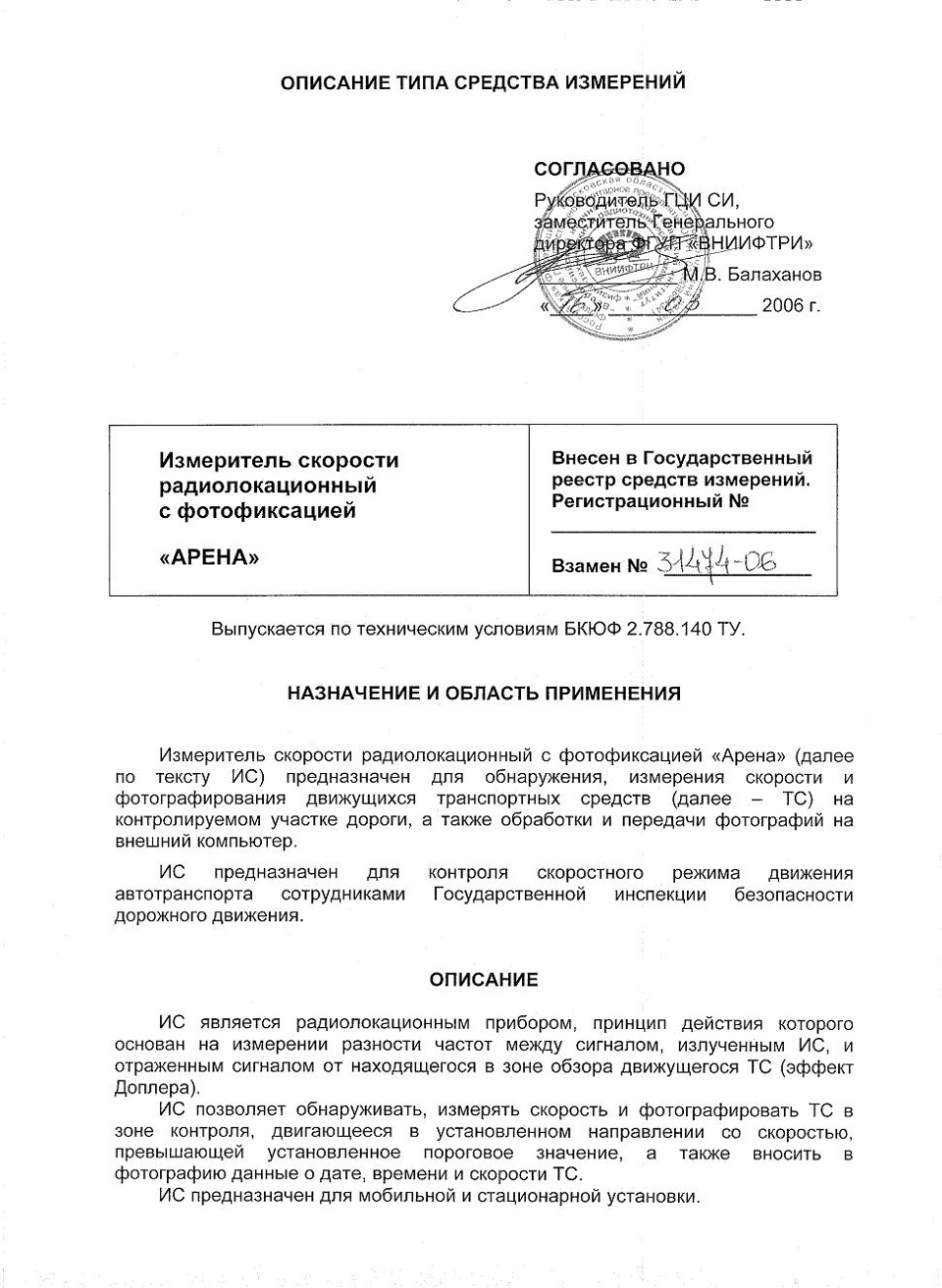
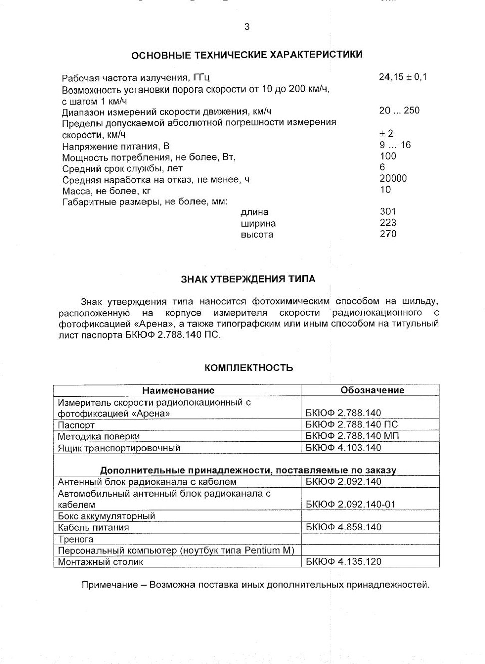
Представляю документацию измерителя скорости радиолокационного с фотофиксацией «АРЕНА» (Описание типа средств измерений, Свидетельство, Паспорт, Руководство пользователя).
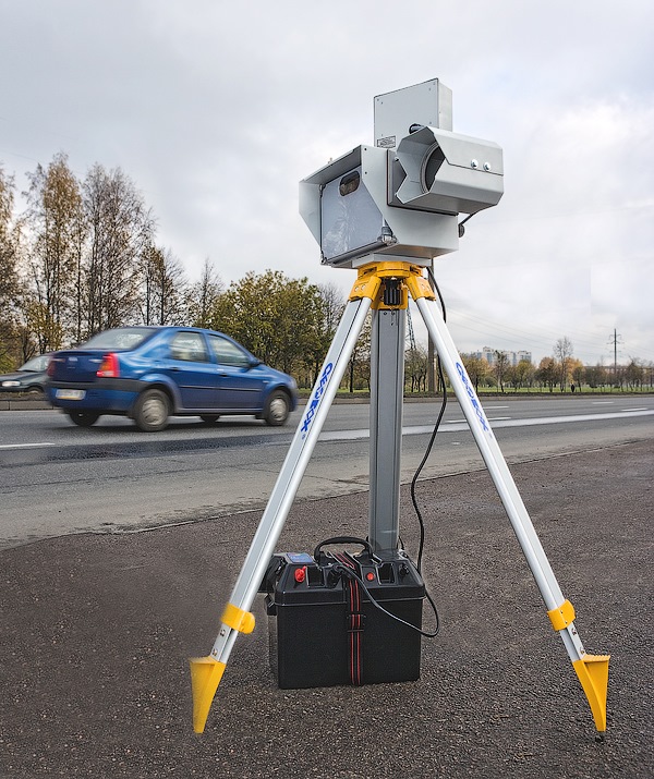
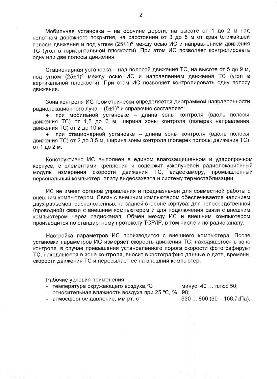
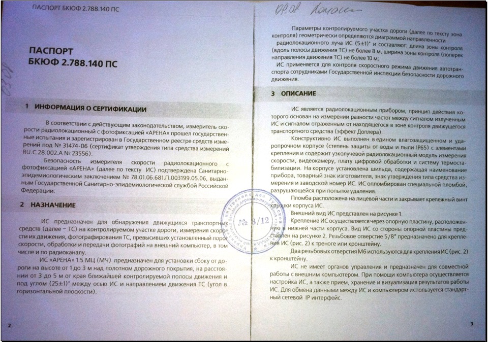
Для себя из документации много узнал нового, как просто общеразвивающую информацию, так и например параметры мобильной установки измерителя скорости «АРЕНА» (что часто встречается для контроля скорости, особенно на загородных трассах):
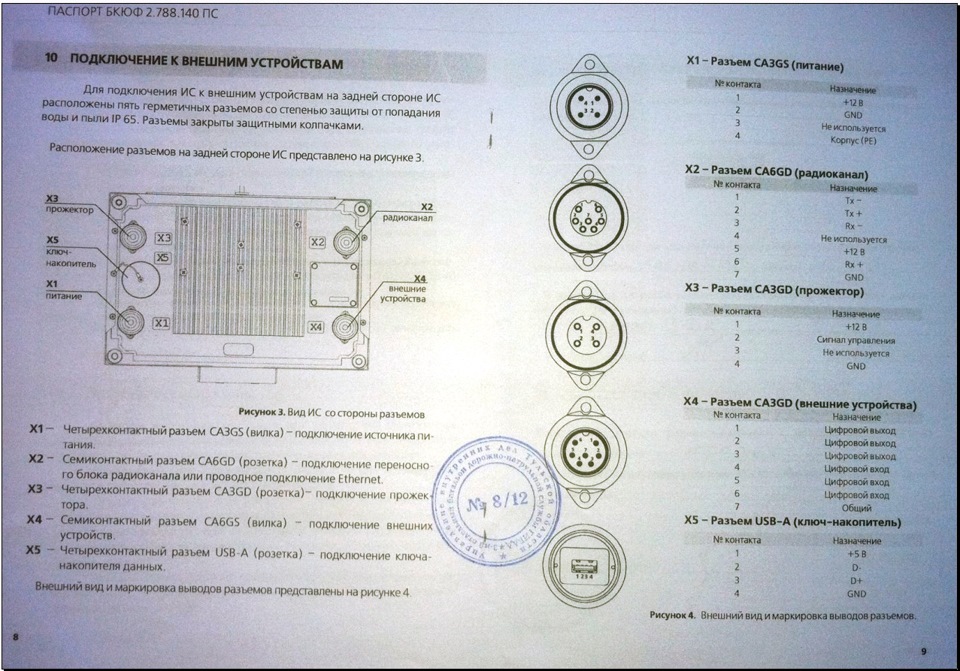
1.установка ИС сбоку от дороге на высоте от 1 до 3 м над полотном дорожного покрытия
2.на расстоянии от 3 до 5 м от края ближайшей контролируемой полосы
3.под углом 25+-1 град между осью ИС и направлением движения ТС (угол в горизонтальной плоскости)
Как видите, например установка ИС «АРЕНА» между элементами дорожного металлического ограждения барьерного типа или иногда можно увидеть еще установку ИС прям на земле — выполнена с грубейшими нарушениями требуемых параметров указанных в документации завода изготовителя применения данного ИС. И т.д.
Часть фотографий можно сказать шпионские, однако они НЕ НОСЯТ грифа ДСП (для служебного пользования) и взяты из открытого доступа (сети Enternet). Каких долгих поисков (в часах и даже днях) мне это стоило!
Производитель: ЗАО «ОЛЬВИЯ» Россия, 194156, Санкт-Петербург, пр. Энгельса д. 27, к. 5 (12В) Тел.Факс: + 7 (812) 326-38-41, 8-800-100-3841 E-Mail: info@olvia.ru и support@olvia.ru (здесь есть некий Сергей Муравьев, который является ведущим инженером по техническому сопровождению)
Должностные лица в лице начальника ГИБДД, начальника ЦАФАП (центра автоматической фиксации административных правонарушений) ГИБДД, руководители производителя сего технического средства под различным предлогом или методом игнорирования запросов не предоставляют их. В период своего поиска информации я написал производителю за период с 05.08.15 г. по 18.08.15 г. — 17 писем (так много потому, что ингорировали, тогда я стал их «закидывать» письмами по 3 адресам info@, admin@, support@) такого содержания
«Здравствуйте!
Скажите пожалуйста:
1. Как можно проверить материал (фото) с передвижного комплекса АРЕНА на подлинность (отсутствие изменений)?
2. Наличие цифровой подписи?
3. Даты и времени съемки?
4. Сколько всего файлов должно быть и в каком формате?
5. Существует ли программа или онлайн-сервис для получения данной информации? Если да не могли бы Вы прислать программу?
Спасибо!
С Уважением … Соломин!»
первый ответ-вопрос я получил, только после 3 письма, через 6 дней, и был он следующий
«Добрый день, … .
Просьба уточнить какую организацию представляете, Ваши ФИО должность и контактный тел.»
Я ответил.
И на конец то 18.08.2015 дали хоть какую-то информацию.
«Здравствуйте, …
Весь сформированный фотоматериал ИС «Арена» имеет цифровую подпись. Дата, время и другие необходимые данные добавляются к фотографии, затем формируется цифровая подпись. Всего формируется два файла, в формате JPEG и SIGN. Программа для проверки на наличие изменений по цифровой подписи для свободного распространения у нас отсутствует.
Если вам потребуется официальный ответ, напишите официальный или адвокатский запрос на имя руководителя предприятия в соответствии с нормами оформления данного типа документов.
Затем перешлите нам скан, после этого ваш запрос будет зарегистрирован и обработан».
Считаю, что Уважающая как минимум себя, серьезная организация сразу отвечает на вопросы по своей технике!
Видимо боятся, что водители узнают о чем-то новом, например о параметрах мобильной установки и будут обращаться с обжалованием постановлений об АПН (административном правонарушении) в суды  — ведь неправильная установка ИС АРЕНА у нас сплошь и рядом; а может проверки целостности и оригинальности фотофайла.
Качество части фотографий мною были улучшены.
Надеюсь может кому пригодится на благо (например для обжалования Постановлений об АПН, настоятельно рекомендую в случае чего делать фотографии и/или видео неправильно установленного ИС АРЕНА — потом пригодятся). Желательно хотя бы раз прочитать данную документацию (Мне нужна была данная инфа для суда).
Остальная часть (продолжение) представлено в «Может кому пригодится во благо, в обжаловании Постановлении об АПН Часть 2 (продолжение)«.
Было бы неплохо в том, чтобы пользователи, автомобилисты почаще и побольше спрашивали производителя (ЗАО «Ольвия) по вопросам касающейся как самой производимой техники, так и материала полученные с их помощью!
Если интересна информация ставте +1, коментарии и т.д! Можете поделится со своими подписчиками ссылкой на запись или продвинуть
ПРОДОЛЖЕНИЕ смотрите в части 2 !
Удачи на дорогах!

-
Page 1
157-1278-904 April 2004 ARENA Hemodialysis Instrument Service Manual 157-1278-905 Rev A April 2004… -
Page 2
157-1278-904 April 2004 Rev A 157-1278-905 Rev A April 2004… -
Page 3
157-1278-904 Rev A April 2004 ARENA Hemodialysis Instrument Service Manual… -
Page 4
Read all warnings, precautions, and instructions included in the Arena Hemodialysis Instrument Operator’s Manual carefully before using the Instrument. The operator’s manual provides the information necessary for the proper operation of the Arena Instrument. It is not a guide to the administration of hemodialysis. -
Page 5
Arena Service Manual Table of Contents Section Date Part Number March 2004 Introduction 157-1278-896 March 2004 Physical Description 157-1278-897 November 2003 Modes of Operation 157-1278-910 January 2004 Hydraulic Theory 157-1278-893 November 2003 Electronic Theory 157-1278-912 November 2003 Temperature Control 157-1278-913… -
Page 6
157-1278-895 Rev A 157-1278-895 Rev A April 2004 April 2004… -
Page 7: Table Of Contents
1. Introduction TABLE OF CONTENTS 1. INTRODUCTION …………3 1.1 General ………….. 3 1.2 Instrument Description ……..4 1.3 Configurations and Options ……5 1.3.1 Standard Features………5 1.3.2 Optional Features ………6 1.4 General Warnings and Cautions ….. 7 1.4.1 Definitions of Terms ……..7 1.4.2 Warnings …………7 1.4.2.1 General……….
-
Page 8
Arena Service Manual 157-1278-896, Rev A March 2004… -
Page 9: Introduction
• Be sufficiently trained in the operation and maintenance of this Instrument and able to distinguish normal from aberrant Instrument behavior. • Be certified by Baxter as trained to service Arena Instruments. The Instrument must: • Be in good working order and certified as such by the attending physician.
-
Page 10: Instrument Description
Arena Service Manual 1.2 INSTRUMENT DESCRIPTION The Instrument provides dialysate at the prescribed temperature and ionic concentration to be used for hemodialysis treatment. It has the ability to monitor Instrument, dialysate and blood circuit functions during dialysis. The Instrument is based on volumetric proportioning, volumetric ultrafiltration control and digital electronics.
-
Page 11: Configurations And Options
1. Introduction 1.3 CONFIGURATIONS AND OPTIONS There are four basic configurations in which the Instrument can be ordered (some are not available in some countries): Single Pump (SP) Single Pump with Pressure Monitoring (SPP) Single Pump with Extras (SPX) Double Pump with Extras (DPX) Each of these configurations has different standard and optional features as shown in this section.
-
Page 12: Optional Features
Arena Service Manual 1.3.2 Optional Features These options may be installed at the factory or in the field. Some of these options are standard depending on the configuration. Other features may not be available in all markets. CONFIGURATION Feature 1571278001…
-
Page 13: General Warnings And Cautions
Use only bloodlines that have been approved by Baxter for use with this Instrument. Before a new style/type of bloodline is used with the Instrument, make sure the…
-
Page 14: Electrical Safety
(mains power switch off) before working with the fan. The fan may start without warning if the Instrument is soft powered off. The Arena Instrument is intended to be operated with a mains ground system. Make sure that the Instrument is properly grounded during operation.
-
Page 15: Olhdf
1. Introduction This Instrument must be connected to an electrical circuit which is protected by a Ground Fault Circuit Interrupter (GFCI) or other leakage current protection device. The protection device must be tested periodically for proper operation. When the Instrument is used in conjunction with other mains powered equipment, the use of the potential equalizer conductor is recommended between the equipment and the Instrument equipotential equalizer…
-
Page 16: Disinfection/Cleaning
Arena Service Manual Handle used blood lines, dialyzers, internal pressure monitoring lines, internal and external transducer protectors, and other extracorporeal circuit components as potentially bio-hazardous waste. Refer to the clinic’s procedures for the disposition of these items. Make sure that the replacement of blood contaminated components is performed in an isolated area to help prevent contamination of personnel and other devices.
-
Page 17: Cautions
1. Introduction Make sure that the determination test shows a sufficiently low level of citric acid or disinfectant in the rinse solution before dialysis. Refer to the attending physician’s directives for the acceptable limit and the AAMI standard for hemodialysis. To ensure that the citric acid level in the dialyzer circuit is below a level acceptable for patient safety, sample the rinse solution in the dialysate lines.
-
Page 18: Fluid
Arena Service Manual • Static damage may not be immediately evident. • Static damage is cumulative. • Both MOS and Bipolar integrated circuits may be damaged by discharge of static electricity. • Both digital and linear integrated circuits may also be damaged.
-
Page 19: Procedural
1. Introduction will increase as well. In these cases, acid rinses or heat clean cycles will not entirely remove the precipitates in the filters. The filters must be replaced. 1.4.3.3 Procedural To prevent possible Instrument damage while unpacking, cut the box only along the line marked CUT ALONG LINE TO OPEN.
-
Page 20: Related Publications
Arena Service Manual 1.5 RELATED PUBLICATIONS • Arena Hemodialysis Instrument Operator’s Manual • Arena Replacement Parts Catalog 1.6 TOOLS AND TEST EQUIPMENT The following tools and supplies are required to properly service the Instrument: • Arena Patient Data Card • Patient Data Card Reader/Writer •…
-
Page 21: Testing After Parts Replacement
Technical Service Bulletin notification and we will notify you by e-mail you when new information becomes available on the Internet. This information may be available as hard copies, or on the Baxter Intranet. 1.9 QUESTIONS AND FEEDBACK If you require further technical assistance in the USA, please call Baxter Instrument Services at 1-800-553-6898.
-
Page 22
Arena Service Manual All service personnel and other authorized users are encouraged to submit corrections and/or suggestions for the improvement of this document. They may be sent to: Global Service Baxter Healthcare Corporation PO Box 1230 Pinellas Park, FL 33780-1230… -
Page 23
3. Instrument Modes TABLE OF CONTENTS 3. INSTRUMENT MODES……….3 3.1 Preparation for Treatment…….. 3 3.2 During Treatment……….5 3.2.1 Prime Mode……….5 3.2.2 Dialyze Mode……….6 3.2.3 Alarm Mode ……….8 3.3 Following Treatment……… 9 3.3.1 Heat Disinfection Mode…….9 3.3.2 Cool Down Mode……..10 3.3.3 Chemical Mode ……….11 3.3.4 Shut Down ……….12 3.3.5 Soft Power Off ………..13… -
Page 24
Arena Service Manual 157-1278-910 Rev A November 2003… -
Page 25: Instrument Modes
3. Instrument Modes 3. INSTRUMENT MODES The term «mode» is used in this Instrument to describe a wide variety of states. This can be confusing unless you understand these modes both from an operator’s perspective and from a service technician’s perspective. Sections 3.1 through 3.3 will address the modes the Instrument goes through from power on through treatment, and then shutdown, Section 3.3 addresses certain options and the associated modes, then Section 3.4 will discuss the…
-
Page 26
Arena Service Manual Table 2-1. Preparation Modes Mode Indications Actions allowed/disallowed Hard Power Off No power is delivered to the instrument. In this mode, normal operation or Calibration Mode is selected. See section 5.2 Hard Power On Backlight, alarm light, and BEEP on Turn soft power on. -
Page 27: During Treatment
3. Instrument Modes 3.2 DURING TREATMENT For each patient, the Instrument must first be primed, and then dialysis started. Although it is not a mode that is selected, the Instrument may also go into an alarm mode requiring action from the operator.
-
Page 28: Dialyze Mode
Arena Service Manual approximately 90 seconds after the blood pump is turned on, the blood pump rate is changed or the UF rate is changed, or the RESET button touched. • The minimum low venous pressure alarm limit is approximately +10 mmHg.
-
Page 29
3. Instrument Modes • The elapsed time is accumulated. • While the blood pump is stopped and/or the Instrument is in bypass, the elapsed time is not accumulated. • The main alarm lamp is off. • The accumulated ultrafiltrate removed is displayed. •… -
Page 30: Alarm Mode
Arena Service Manual • A manual blood pressure reading may be taken. • The blood pressure schedule may be set, changed or manually stopped. 3.2.3 Alarm Mode 3.2.3.1 Instrument status window displays ALARM 3.2.3.2 Instrument action • An alarm indicator flashes to indicate the monitor that is in alarm.
-
Page 31: Following Treatment
3. Instrument Modes 3.3 FOLLOWING TREATMENT In accordance with clinic procedures, the operator may choose one of several disinfection processes following a treatment, at the end of a shift, or at other times. For more on disinfection, see Section 9, Disinfection. The steps to Instrument Auto Off are dependent on the type of disinfection (if any) used prior to shutdown.
-
Page 32: Cool Down Mode
Arena Service Manual • The operator may manually start the Cool Down Mode. (See Warning in Section 3.3.2.) • After completion of the circulating period, the Cool Down Mode is automatically started. • The Event Timer is available. For instruments with the Blood Pressure Monitor option: •…
-
Page 33: Chemical Mode
3. Instrument Modes • The heparin pump, dialysate flow rate, conductivity, temperature, prescribed time, target UF, TMP and UF rate functions cannot be accessed/changed. • The UF rate is 3.60 L/h. • The Event Timer is available. For instruments with the Blood Pressure Monitor option: •…
-
Page 34: Shut Down
Arena Service Manual • Main alarm lamp is off (except for operator prompts and error situations). • Audio alarm is muted (except for operator prompts and error situations). • The blood pump will not operate. • The heparin pump, dialysate flow rate, conductivity, temperature, prescribed time, target UF, TMP and UF rate functions cannot be accessed/changed.
-
Page 35: Soft Power Off
3. Instrument Modes • Main alarm lamp flashes. • The operator is prompted to turn off the power. 3.3.5 Soft Power Off 3.3.5.1 Instrument status window displays Display is off 3.3.5.2 Instrument action • The front panel power switch is off. •…
-
Page 36
Arena Service Manual 3-14 157-1278-910 Rev A November 2003… -
Page 37
4. Hydraulic Theory TABLE OF CONTENTS 4. HYDRAULIC THEORY ……….3 4.1 Overview…………3 4.2 Dialysate Circuit……….4 4.2.1 Incoming Water Pressure Regulator ….4 4.2.2 Water On/Off Valve……..5 4.2.3 Heat Exchanger ……….5 4.2.4 Heater, Thermistor, Safety Thermostat..5 4.2.5 Concentrate Line Regulator(s) and Concentrate Central Delivery Systems (optional)………..6 4.2.6 Volumetric Proportioning System ….6… -
Page 38
Arena Service Manual 157-1278-893 Rev A January 2004… -
Page 39: Hydraulic Theory
4. Hydraulic Theory 4. HYDRAULIC THEORY 4.1 OVERVIEW The Arena Instrument is designed to heat incoming water to approximately human body temperature, mix the water with dialysate concentrate in physiologically correct proportions and infuse the dialysate through an artificial kidney to effect hemodialysis therapy.
-
Page 40: Dialysate Circuit
Arena Service Manual Figure 4-2. Standard Hydraulics Module, Rear View 4.2 DIALYSATE CIRCUIT 4.2.1 Incoming Water Pressure Regulator The pressure of the incoming water is reduced and stabilized by the adjustable water pressure regulator to the factory- recommended level (see Section 18, Calibration Procedures).
-
Page 41: Water On/Off Valve
4. Hydraulic Theory 4.2.2 Water On/Off Valve This valve is actuated through a coil using unregulated +24 VDC. When the power is off, the valve is closed preventing water from entering the Instrument. When power is on, the on/off valve operation is controlled by the supply manifold level sensor signal.
-
Page 42: Concentrate Line Regulator(S) And Concentrate Central Delivery Systems (Optional)
Arena Service Manual (225°F). The thermostat turns off power to the heater to prevent damage in case of a runaway temperature circuit failure. For testing purposes, the heater has a resistance of approximately 10-20 Ω when cold. The thermistor has a resistance of approximately 3 KΩ…
-
Page 43
4. Hydraulic Theory Figure 4-5. Supply Manifold 4.2.7.1 “A” Mix Chamber and Air Gap As the name implies, the “A” mix chamber mixes the water and “A” concentrate into a uniform solution. The air gap at the top of this chamber is at atmospheric pressure, which helps to limit proportioning errors. -
Page 44
Arena Service Manual water on/off valve. When the magnet is above the sensor, the condition indicates the air trap is full, closing the incoming water on/off valve. In normal operation, as the supply pump draws solution from the air trap chamber to fill the flow equalizer, the liquid level in the chamber is lowered along with the float causing the water on/off valve to open so water again fills the chamber. -
Page 45: Air Removal System
4. Hydraulic Theory 4.2.8 Air Removal System The air removal system removes dissolved gases that are trapped in the water used to make up dialysate. The air removal system consists of the air removal sprayer, the air removal pump, and the vented air trap.
-
Page 46
Arena Service Manual “B” conductivity probe, the supply pressure pump, and the supply pressure regulator. Figure 4-7 describes this loop. The loop configuration helps to mix the bicarbonate concentrate by recirculating the solution through the “B” mix chamber. The loop also acts as a conduit for flow that is diverted by the supply pressure regulator at the end of each flow equalizer fill cycle. -
Page 47
4. Hydraulic Theory Figure 4-8. «B» Probe/Thermister Set The second conductivity probe in the flow path is located at the outlet of the “B” mix chamber in the dialysate supply recirculation loop. The probe/thermistor set is identical to the “A” conductivity probe/thermistor set. -
Page 48: Input Pressure Equalizer, Flow Equalizer, And Output Pressure Equalizer
Arena Service Manual 4.2.10.5 Supply Pressure Regulator The supply pressure regulator controls the peak input pressure to the «pre» side of the input pressure equalizer. When the flow equalizer cavity is filled, the pressure in the pressure regulator increases to its maximum value (16 psi ±1), overcoming the spring force of the regulator spring allowing the dialysate to recirculate back to the “B”…
-
Page 49
4. Hydraulic Theory Figure 4-9. Optical Sensor Assembly The diaphragm has four flaps that will open under a pressure of 0.5 PSI, allowing the light from the LED to go across the assembly and reach the Detector (see Figure 4-10). This will indicate that dialysate is flowing. -
Page 50: Dialysate Monitoring Manifold
Arena Service Manual Figure 4-10. Optical/Diaphragm Sensors for EOS 4.2.13 Dialysate Monitoring Manifold The purpose of this assembly is to house the components to monitor the dialysate temperature, conductivity and pressure. This manifold contains: The dialysate (primary) conductivity probe/thermistor set…
-
Page 51
4. Hydraulic Theory Figure 4-11. Dialysate Monitoring Manifold 4.2.13.1 Dialysate (Primary) Conductivity Probe/Thermistor This is one of three conductivity probe sets. The other two are described in Section 4.2.7.4, «A» Conductivity Probe/Thermistor Set, and Section 4.2.10.3, «B» Conductivity Probe/Thermistor Set. Figure 4-12. -
Page 52: Dialysate Bypass Valve And Sensor
Arena Service Manual equalizer. This probe set is identical to the other conductivity probe sets. It measures the total conductivity of the dialysate before it enters the artificial kidney. This temperature- compensated conductivity value is displayed in the CONDUCTIVITY window. The primary conductivity alarm circuit also uses the signal from this probe.
-
Page 53: Rinse Block
4. Hydraulic Theory While in Rinse Mode, the Instrument will automatically go into Bypass Mode periodically. There is also a manual Bypass Mode that permits the operator to put the Instrument in bypass when a dialyzer is connected or sequential ultrafiltration therapy is performed. This manual Bypass Mode is activated via the Bypass switch located on the Membrane Switch Panel.
-
Page 54: Blood Leak Detector
Arena Service Manual Supply Pressure Regulator Input Pressure Equalizer Flow Equalizer Output Pressure Equalizer Dialyzer Connectors and Dialyzer Check Valve Dialysate Pressure Pump Flow Restrictor UF Removal Regulator UF Flow Meter Refer to Section 8, Ultrafiltration Control, for more information on the UF System.
-
Page 55: Heat Disinfection Recirculation Valve
4. Hydraulic Theory The rinse valve is open in the Rinse and Prime Modes, in Self Test (except UF test) and in the Calibration Mode when the UF Flow Meter is being calibrated. Therefore, when the dialyzer connectors are not connected to the Instrument, the rinse valve must be closed. 4.5.2 Heat Disinfection Recirculation Valve The heat disinfection recirculation valve diverts the effluent water back into the input side of the heater (with the water on/off closed)
-
Page 56
Arena Service Manual 4-20 157-1278-893 Rev A January 2004… -
Page 57
Air Gap CONFIDENTIAL CONFIDENTIAL INFORMATION INFORMATION Drain UNLESS OTHERWISE SPECIFIED UNLESS OTHERWISE SPECIFIED DESCRIPTION DESCRIPTION Arena Standard Hydraulics Flow Diagram DIMENSIONS ARE IN INCHES. DIMENSIONS ARE IN INCHES. TOLERANCES ARE: TOLERANCES ARE: DECIMALS DECIMALS ANGLES ANGLES DWG No. DWG No. -
Page 58
5.7.3 Test Points……….36 5.7.4 Bypass System and Flow Sensor ….38 5.8 I/O Electronics Power Board ……39 5.9 Peripheral Interface Boards ……41 5.9.1 Functional ……….44 5.9.2 Electrical …………44 5.10 Fuses …………. 46 Arena Interconnect Diagram……… 47 157-1278-912 Rev A November 2003… -
Page 59
Arena Service Manual 157-1278-912 Rev A November 2003… -
Page 60: Electronic System Architecture
5. ELECTRONIC SYSTEM ARCHITECTURE 5.1 OVERVIEW This section describes the electronic system architecture of the Arena Dialysis Delivery System. Some details may vary for individual Instruments according to the options installed. While reviewing this section it is recommended that you refer to the Input/Output Diagrams when available that correspond to the specific circuits being described.
-
Page 61
Arena Service Manual Figure 5-1. Interconnect Block Diagram 157-1278-912 Rev A November 2003… -
Page 62: Soft And Hard Power On/Off
5. Electronics 5.2 SOFT AND HARD POWER ON/OFF The power line circuit breaker/mains switch is used to Hard Power On and Off the Instrument. When this switch is in the Off position the Instrument is Hard Powered Off and all power is removed from the Instrument;…
-
Page 63: Power System
Arena Service Manual 5.3 POWER SYSTEM 5.3.1 Power Requirements The Instrument requires a nominal input voltage of 110, 120, 230 or 240 VAC. Input voltage must be within ±10% of the rated nominal value. Typical input current in a 120 VAC Instrument is approximately 3 A when the heater is Off.
-
Page 64
In the event of excessive current draw by the Instrument, the circuit breaker will trip thus protecting the Arena. Both sides of the power line are broken by the circuit breaker. The power line circuit breaker/mains switch supplies non- isolated power directly to two loads: the dialysate heater and the power transformer. -
Page 65
Arena Service Manual Figure 5-4. Terminal Block and Fuse F1 • Terminal Block Fuse F1. This fuse is located in the Terminal Block. It is a 2 A, 250 VAC replaceable fuse that protects the transformer from a short-circuit in the output 120 VAC line. -
Page 66
5. Electronics Figure 5-5. Input Circuit Breaker and Isolation Power Transformer • Input Circuit Breaker CB2. This is a 6 amp push-button input circuit breaker in series with the power transformer primary winding that protects the input 120 VAC line to the Isolation Power Transformer. -
Page 67
Arena Service Manual Figure 5-6. Input (Primary) 120 and 230 VAC Configurations The transformer has three isolated secondary windings, with output voltages equal for all options: • 21 VAC, this is actually a winding with a middle tap, so there are two 21 VAC lines and one common line that supply power to the Unregulated Power Supply. -
Page 68
5. Electronics Figure 5-7. Isolation Power Transformer Options • +24 VDC Unregulated Power Supply (+29.5 +/- 3 VDC) This power supply rectifies and filters the 21 VAC from the Isolation Power Transformer into unregulated nominal +24 VDC. The expected voltage reading from this power supply is +29.5 ±… -
Page 69
Arena Service Manual Figure 5-8. Unregulated Nominal +24 VDC Power Distribution 5-12 157-1278-912 Rev A November 2003… -
Page 70
5. Electronics Figure 5-9. Switching Power Supply • Switching Power Supply. This power supply rectifies and filters the 120 VAC from the Isolation Power Transformer. This board has an internal 3A/250 VAC fuse. This power supply provides +5 VDC and ground for the digital circuits, and +12 and -12 VDC and ground for the analog signal conditioning circuits in all boards. -
Page 71
Arena Service Manual The Passive Backplane filters and distributes the +5, +12 and -12 VDC to all boards in the Card Cage. These boards in turn distribute power to the Power Boards: o Blood Pump Power Board o UF-Proportioning Power Board… -
Page 72
5. Electronics Figure 5-10. Low Voltage Power Distribution 157-1278-912 Rev A 5-15 November 2003… -
Page 73: Card Cage
Arena Service Manual 5.4 CARD CAGE CAUTIONS 1. Use proper ESD protection when handling or contacting any ESD sensitive components. 2. Always repackage the removed ROMs or boards in the original ESD packaging. The Card Cage houses the electronic boards that will control the operation of the Instrument.
-
Page 74: Slot # 1: 4-Comm (Touch Screen) Board
5. Electronics • Slot # 5: Single (or optional Double) Blood Pump Controller • Slot # 6: Input/Output Controller • Slot # 7: UF-Proportioning Controller • Slot # 8: Memory Board These boards are interconnected through the Backplane located at the back, inside the Card Cage.
-
Page 75: Slot # 2: Single Board Computer (Sbc)
Arena Service Manual 5.4.2 Slot # 2: Single Board Computer (SBC) The SBC (sometimes also called Motherboard or Host board) is highly integrated, combining video and networking functions in a single board. 5.4.2.1 Hardware The Instrument is controlled by an Intel Pentium II MMX 266 MHz microprocessor, and three 8040 microcontrollers.
-
Page 76: Sdram Installation
5. Electronics stores programs and data currently being used so they are accessible to the microprocessor. The SDRAM and Compact Flash Memory are not included in the SBC spare, therefore both need to be removed from old SBC and placed on the new SBCs. Follow the next procedure to install the SDRAM on the SBC.
-
Page 77: Bios
Arena Service Manual Figure 5-14. Completed Installation 5.4.2.3 BIOS The Basic Input/Output System (BIOS) program resides in a 256- KB ROM located on the SBC. The BIOS is immediately activated when the Instrument is first hard power on. The BIOS begins the process of checking out the system and configuring it through the Power-On Self Test.
-
Page 78: Operating System Software (Host)
5. Electronics Pump(s), UF- Concentrate Proportioning, and Input/Output systems. The I/O Controller functions as a watchdog for the Pentium, forcing the system into a nonfunctional safe state if the Pentium discontinues its interprocessor communication. 5.4.2.5 Operating System Software (Host) The host control software (operating system) is loaded into the 64 MB programmable read only Compact Flash Memory.
-
Page 79
Arena Service Manual • Accept operating information and parameters from the user via the video display touch screen and touch screen controller (for example, blood flow rate, dialysate temperature, UF rate). • Display operating conditions and status on the video display. -
Page 80: Slot # 4: Hemavision Board (Optional)
5. Electronics The SBC filters out the Rinse request from the I/O controller when the dialyzer line interlocks are not in the proper state. The only way the SBC can receive a Rinse request without the proper interlock condition being met is if a failure exists in the system logic.
-
Page 81
Arena Service Manual This board is physically identical to the UF-Proportioning Controller board. There is a different EEPROM for the Double Pump version of the board. The board has a jumper, shown in Figure 5-16, which must be properly placed according to the next Table 5-3, depending on the functions that the board will perform. -
Page 82: Slot # 6: Input/Output Controller
5. Electronics 5.4.5 Slot # 6: Input/Output Controller This board controls the operation of the I/O Hydraulics Power and I/O Electrical Power Boards, which together form the I/O Control System. Thirteen subsystems are controlled or monitored by the I/O Control system. They are as follows: •…
-
Page 83: Slot # 8: Memory Board
• Constants that allow the Instrument to be customized, such as the Date Format, Bleach Name, etc. WARNING Calibration constants must only be changed by authorized Baxter personnel or by specific instructions provided by Baxter. 5-26 157-1278-912 Rev A November 2003…
-
Page 84
5. Electronics Figure 5-17. Memory Board The Memory Board provides the following additional functions: 1. System ground and +5 VDC test points 2. Connector for the external Reed Service Switch 3. Address decoding for both memory and I/O devices 4. Treatment Event Log with memory allocated to store the most recent 20 treatment errors, providing date, time and index information 5. -
Page 85
Arena Service Manual Note When DIP Switch 1 is ON, it allows the Instrument to enter Service/Calibration Mode. The external Reed Service Switch is connected in parallel to this switch and can be used to momentarily turn on Switch 1. -
Page 86
5. Electronics • Dialysate Flow • Dialysate Temperature • Blood Flow • HCT Limit • Adjusted NA • Adjusted BC • Sodium Profile • Bicarbonate Profile 157-1278-912 Rev A 5-29 November 2003… -
Page 87: Blood Pump Power Board
Arena Service Manual 5.5 BLOOD PUMP POWER BOARD This board is controlled directly by the Blood Pump Controller board. It is located right behind and above the blood pumps. The BP Power board in turn controls the operation of the analog devices related to the blood pump system (see Figure 5-1): •…
-
Page 88: Fuses
5. Electronics Figure 5-18. UF-Proportioning and I/O Hydraulic Power Board Locations 5.6.1 Fuses This board incorporates 17 fuses as shown in Table 5-5. Fuses may be removed by grasping them in the center with small pliers. Table 5-5. UF-Proportioning Power Board Fuses FUSE FUSE CIRCUIT PART NO.
-
Page 89: Light-Emitting Diodes (Leds)
Arena Service Manual Figure 5-19. UF-Proportioning Power Board Fuses 5.6.2 Light-emitting Diodes (LEDs) The light-emitting diodes (LEDs) on the UF-Proportioning Power board are located close to the connector for the indicated component drive. See Figure 5-20 for these locations indicated in red.
-
Page 90: Test Points
5. Electronics 5.6.3 Test Points The test points on the UF-Proportioning Power board are listed in the following table. Frequently used test points are marked with an asterisk (*). See Figures 5-20 for test point locations shown in blue. The +24 V supply can be tested across the large capacitor (C56) near the 60-pin ribbon cable connector.
-
Page 91
Arena Service Manual Figure 5-20. UF-Proportioning Power Board with Surface Mount Technology (Test points are highlighted in blue, LEDs in red, and fuses in green.) 5-34 157-1278-912 Rev A November 2003… -
Page 92: I/O Hydraulics Power Board
5. Electronics 5.7 I/O HYDRAULICS POWER BOARD This board is controlled directly by the Input/Output Controller board. The I/O Hydraulics Power board in turn controls the operation of the following analog devices related mostly to the fluid path system (see Figures 5-1 and 5-18): •…
-
Page 93: Light-Emitting Diodes (Leds)
Arena Service Manual 5.7.2 Light-emitting Diodes (LEDs) Table 5-9. Hydraulics Power Board LEDs FUNCTION COLOR Flow Green +24 VDC Switched Green +24 VDC Green Heat Green Purge Valve HDF Green Bypass Green +12 VDC Green +5 VDC Green -12 VDC…
-
Page 94
5. Electronics Figure 5-21. I/O Hydraulics Power Board with Surface Mount Technology (Test points are highlighted in blue, LEDs in red, and fuses in green.) 157-1278-912 Rev A 5-37 November 2003… -
Page 95: Bypass System And Flow Sensor
Arena Service Manual 5.7.4 Bypass System and Flow Sensor Single Board Computer Figure 5-22. Bypass System The Bypass Mode is initiated when a primary dialysate alarm is detected by the I/O Controller board, when a redundant dialysate alarm is detected by the UF-Proportioning Controller board, when the host requests bypass, or when the manual bypass button is pushed.
-
Page 96: I/O Electronics Power Board
5. Electronics second thermistor uses thermal dilution to sense the fluid flow. The voltage outputs from the thermistors on the I/O Hydraulics Power board drive A/D input channels on the I/O Controller board where they are converted to 10 bit digital values. A software algorithm in the I/O Controller code uses these inputs to determine the flow condition.
-
Page 97
Arena Service Manual Figure 5-23. On/Off State, Audio Alarm, and Power Fail The power fail alarm circuitry includes a CMOS power state flip- flop powered by a 1 Farad (F) capacitor. The flip-flop, which can be toggled by either the front panel power button or the Pentium system controller, provides the following functions: •… -
Page 98: Peripheral Interface Boards
5. Electronics 5.9 PERIPHERAL INTERFACE BOARDS The Peripheral Interface Boards consist of the Peripheral Interface Board and the Rear Passive Interconnect Panel (two passive boards containing only connectors). The Peripheral Interface Boards provide a physical link, communications, and power between some of the SBC ports and the peripheral devices.
-
Page 99
Arena Service Manual Figure 5-26. Rear Passive Interconnect Panel (Interior Views) The interface boards provide the necessary circuitry required to create a link between the parallel port of the SBC and the following peripherals: • Patient Data Card Reader • Sodium Button pendant •… -
Page 100
5. Electronics 4 Port Serial Board Single Board Computer Ethernet Serial Port Parallel Port Ethernet NIBP Status Lamp Driver Sodium Button Driver +12V Isolated Patient Data Card -12V RS232 Reader Interface Reader Driver Unreg Peripheral Interface Board +24V Isolated 20VAC Spare Sodium Button Status Lamp… -
Page 101: Functional
Arena Service Manual 5.9.1 Functional • Power. This section provides power to the Peripheral Interface Board and its peripherals. • Parallel Port. The Peripheral Interface Board is directly connected to the SBC’s parallel port. The parallel port controlled section comprises three functions: Status Lamp, Sodium Button, Patient Data Card Reader.
-
Page 102
5. Electronics Table 5-11. Peripheral Interface Board LEDs and Fuses LEDS/FUSES SYSTEM PART NO. Patient Data Card Power (software controlled) Sodium Button Pendant Switch pressed (hardwired) Patient Data Card Inserted (hardwired) Fuse 1 +24 VDC to the 3-Light Status 4560388015 Lamp Rated @ 0.25 A, 125 VAC Fuse 2… -
Page 103: Fuses
Arena Service Manual 5.10 FUSES Fuses for the UF-Proportioning Power board, Hydraulics Power board and Peripheral Interface boards are found in Tables 5-5, 5-8 and 5-11. Table 5-12 is a listing of all additional fuses and circuit breakers used on the Instrument.
-
Page 104: Arena Interconnect Diagram
5. Electronics ARENA INTERCONNECT DIAGRAM Remove this page before printing. 157-1278-912 Rev A 5-47 November 2003…
-
Page 105
RJ45 Temperature +5 VDC Alarm Lamp Power Sensor Detector PI44 Lower Chassis Peripheral Devices PI02 Rear Connection Panel Red Solid Line- Power Arena Interconnect Diagram Blue Dotted Line-Communication Green blocks- Printed Circuit Boards Ribbon Cable Rev A 11-03-03 157-1278-586 Connector… -
Page 106
6. Temperature Control TABLE OF CONTENTS 6. TEMPERATURE CONTROL ………3 6.1 Overview…………3 6.2 Temperature Control and Back Up Temperature Alarm ……..3 6.3 Temperature Monitoring and Primary Temperature Alarm ……..6 6.4 Automatic Safety Tests ……..7 6.5 Internal Cabinet Temperature Control …. 8 157-1278-913 Rev A November 2003… -
Page 107
Arena Service Manual 157-1278-913 Rev A November 2003… -
Page 108: Temperature Control
6. Temperature Control 6. TEMPERATURE CONTROL 6.1 OVERVIEW The Arena Instrument accurately and safely controls the temperature of the dialysate using a redundant system. This redundancy involves two electronic signals that pass through separate electronic pathways (the UF-Proportioning and the I/O…
-
Page 109
Arena Service Manual A/D converter on the UF-Proportioning Controller board. The signal has calibration factors applied and the result is compared to the user-requested temperature. The second and third thermistors are contained in the “A” and “B” conductivity probes. The «B» thermistor is used to generate a redundant backup high alarm and provides fine control of the temperature. -
Page 110
6. Temperature Control set temperature by more than 0.05°C, then the control temperature threshold sent to the UF–Proportioning controller is updated, changing the temperature control so that the “B” conductivity probe temperature will equal the user-set temperature. Using this correction routine, the dialysate temperature at the “B”… -
Page 111: Temperature Monitoring And Primary Temperature Alarm
Arena Service Manual Figure 6-1. Temperature Control Block Diagram 6.3 TEMPERATURE MONITORING AND PRIMARY TEMPERATURE ALARM This system is managed by the I/O and Hydraulics boards. The temperature monitoring follows steps similar to temperature control: 1. The operator enters the desired dialysate temperature…
-
Page 112: Automatic Safety Tests
6. Temperature Control board for comparison against the primary temperature alarm limits as well as temperature compensation for the primary conductivity. 4. The I/O Hydraulics Power board reads the temperature from the primary temperature probe. 5. The I/O Controller board reads and converts into a digital signal the primary (dialysate) temperature probe signal from the I/O Hydraulics Power board, and sends this information to the SBC.
-
Page 113: Internal Cabinet Temperature Control
Arena Service Manual The following tests are therefore performed during Self Test to guarantee a fully functional system. 1. Primary probe temperature measurement accuracy test The SBC compares the I/O Controller’s primary probe measurement with the UF-Proportioning Controller’s measurement of the “B” probe’s temperature reading and verifies that they are within 1°C of each other.
-
Page 114
6. Temperature Control Figure 6-2. Cabinet Temperature Control The air rises, and positive pressure and thermal convection combine to exhaust the warmed cabinet air out the top of the instrument through exhaust vents on the upper back and upper display back of the Instrument. The cabinet cooling system consists of the following major components: Table 6-1. -
Page 115
Arena Service Manual cabinet (10 mV/°C). These temperature readings are input to the fan control software. The fan control software cycles the fan on and off with a hysteresis of 2°C at the temperature threshold; i.e., at 38°C the fan turns on, and at 36°C the fan turns off. -
Page 116
7. Dialysate Preparation TABLE OF CONTENTS 7. DIALYSATE PREPARATION ……..3 7.1 Dialysate Proportioning ……..3 7.2 Sodium and Bicarbonate Profiling ….5 7.3 Volumetric Proportioning System….5 7.3.1 Overview…………5 7.3.2 “A” and “B” Concentrate Reciprocating Rotating Piston Pumps……8 7.4 Dialysate Proportioning Control….10 7.5 Dialysate Flow Control …….. -
Page 117
Arena Service Manual 157-1278-914 Rev A January 2004… -
Page 118: Dialysate Proportioning
Rinse Mode, before starting Self-test and the dialysate selections made in Calibration (Service) Mode. There are two types of concentrates that can be used in the Arena Instrument: Acetate and Bicarbonate. • Acetate dialysate proportioning. Acetate proportioning requires 34 parts water to 1 part acetate concentrate.
-
Page 119
Arena Service Manual reading the “A” and “B” concentrate port interlock information. Proximity sensors on the “A” and “B” concentrate ports relay the information on whether the “A” and “B” concentrate fittings are in their respective ports. When the concentrate connector is in the… -
Page 120: Sodium And Bicarbonate Profiling
7. Dialysate Preparation 7.2 SODIUM AND BICARBONATE PROFILING Sodium and Bicarbonate Profiling permits the operator to set the sodium and bicarbonate levels for the entire treatment. The sodium and bicarbonate levels are changed in adjustable time increments (15, 30 or 60 minutes) throughout the dialysis treatment.
-
Page 121
Arena Service Manual Figure 7-2. Hydraulic Diagram 157-1278-914 Rev A January 2004… -
Page 122
The “B” concentrate pump delivers 1.83 mL of bicarbonate concentrate. Filling the rest of the bucket with 34 mL of water completes the proportioning of the dialysate. Volumetric Flow Equalizer Figure 7-4. Arena Volumetric Proportioning 157-1278-914 Rev A January 2004… -
Page 123: A» And «B» Concentrate Reciprocating Rotating Piston Pumps
Arena Service Manual Instead of the bucket, the water volume is measured by the volumetric flow equalizer. This volumetric flow equalizer fills with a very precise volume of fluid and the Instrument knows this volume. Based on the flow rate and the concentrate type, the Instrument calculates the amount of the acetate or acid and bicarbonate required per stroke of the flow equalizer.
-
Page 124
7. Dialysate Preparation On the suction stroke, the piston is pulled toward the stepper motor drawing in concentrate. The piston is also rotating as it draws in the concentrate. When it reaches a null point (the end-of-stroke), the flow into the pump is stopped. The piston continues to rotate until it opens to an outlet into the Instrument. -
Page 125: Dialysate Proportioning Control
Arena Service Manual 7.4 DIALYSATE PROPORTIONING CONTROL The UF-Proportioning system controls the concentrate(s) to water proportioning ratios by controlling the dialysate flow rate, and the “A” and “B” concentrate flow rates. The “A” and “B” concentrate pumps are stepper motor driven piston pumps that deliver a calibrated volume of concentrate per stepper motor revolution (see Section 7.3.2).
-
Page 126: Dialysate Flow Control
7. Dialysate Preparation Using the dialysate flow rate, sodium and bicarbonate profiles, sodium button and the proportioning ratios, the SBC determines the associated concentrate flow rates and stores the two concentrate pump speeds in the UF–Proportioning controller. The 4-phase, 100-step/rev stepper motors used in the concentrate pumps are driven in a 2-phase bidirectional mode.
-
Page 127: Supply Pump
Arena Service Manual 7.5.3 Supply Pump The supply pump speed can continually adjust throughout operation. Its speed is calculated at each flow equalizer stroke so end-of-stroke times of one second are achieved. See Figure 7-7. Figure 7-7. Dialysate Flow The UF-Proportioning system controls the dialysate flow rate by…
-
Page 128: Pump Drive Circuitry
7. Dialysate Preparation the time it expects the end-of-stroke signal and then switches the flow equalizer valves (secondary flow equalizer time-out). To ensure a complete volume transfer in the flow equalizer, flow sensors (end-of-stroke sensors) have been placed in the flow path to sense when the flow stops (end-of-stroke).
-
Page 129: End-Of-Stroke Sensors
Arena Service Manual 7.5.7 End-of-stroke Sensors Flow detection is accomplished by an optical sensor. For more information on this sensor, refer to Section 4, Hydraulic Theory. 7.6 CONDUCTIVITY MEASUREMENT AND MONITORING Conductivity is used as a measurement of the electrolyte composition of the dialysate.
-
Page 130
7. Dialysate Preparation • An acid (or acetate) conductivity probe (referred to as the “A” conductivity probe) which is used to monitor that the acid and water were mixed correctly. This probe is located in the supply manifold. • A bicarbonate conductivity probe (referred to as the “B” conductivity probe) which is used to monitor that the addition of bicarbonate concentrate increased the conductivity of the dialysate by an appropriate amount. -
Page 131: Conductivity Calibration
Arena Service Manual Figure 7-8. UF-Proportioning Temperature / Conductivity Block Diagram 7.6.3 Conductivity Calibration Refer to Section 18, Calibration/Adjustments, for the actual calibration procedure. The conductivity probes are calibrated in the Calibration Mode. The resistance of each probe is measured at a known conductivity and temperature (by the use of an external reference meter) for the scaling of the probe’s base resistance in the outlet relationship.
-
Page 132: Central Concentrate Supply Systems
7. Dialysate Preparation proportional to the negative peak of the AC stimulation voltage. The other is proportional to the negative peak of the probe’s AC current. The ratio of the voltages is proportional to the resistance of the respective probe. The resistance of the probes has been modeled as a function of temperature and conductivity.
-
Page 133
Arena Service Manual There are connections for three different acid concentrates and one bicarbonate concentrate from the central delivery supply system to the back of the Instrument. These go through the Instrument and directly connect to the supply fittings on the front of the Instrument as shown in Figure 7-9. -
Page 134
7. Dialysate Preparation same type of tubing used in the standard concentrate line (part number T010500). WARNING Instrument concentrate lines longer than standard will affect the effectiveness of the heat clean and chemical disinfection cycle. CAUTION It is essential that all central concentrate supplies be equipped with a manual shut-off valve at each Instrument position. -
Page 135
Arena Service Manual 7-20 157-1278-914 Rev A January 2004… -
Page 136
8. Ultrafiltration TABLE OF CONTENTS 8. ULTRAFILTRATION …………3 8.1 Overview…………3 8.2 UF Removal …………4 8.3 Description …………5 8.3.1 Supply Pump ……….8 8.3.2 Particle Filter («Post» Supply Pump) …9 8.3.3 Supply Pressure Regulator……9 8.3.4 Input Pressure Equalizer …….9 8.3.5 Flow Equalizer ……….11 8.3.5.1 Phase 1………. -
Page 137
Arena Service Manual 157-1278-915 Rev A January 2004… -
Page 138: Ultrafiltration
8. Ultrafiltration 8. ULTRAFILTRATION 8.1 OVERVIEW The Arena Instrument accurately controls fluid removal. A volumetric flow equalizer controls and balances dialysate to and from the dialyzer. The volume of fresh dialysate measured and delivered to the dialyzer by the predialyzer side of the flow equalizer is equal to the volume of used dialysate removed from the dialyzer by the postdialyzer side of the flow equalizer.
-
Page 139: Uf Removal
Arena Service Manual Figure 8-2. UF Flow Meter The flow through the UF flow meter is displayed in the UF RATE window. The fluid that passes through the UF flow meter is not entirely ultrafiltrate. It is volumetrically equivalent to the patient’s ultrafiltrate.
-
Page 140: Description
8. Ultrafiltration Mode. This value remains during the Rinse Mode and is cleared upon the entry of the Self Test Mode. In Rinse Mode, the UF removal rate is 3.6 L/h and the screen indicates no UF volume accumulated. During the Self Test Mode, no UF removal occurs except for during specific self tests performed by the Instrument (no UF volume is accumulated).
-
Page 141
Arena Service Manual Figure 8-3. Hydraulics Module, Front Side 157-1278-915 Rev A January 2004… -
Page 142
8. Ultrafiltration Figure 8-4. Hydraulics Module, Back Side 157-1278-915 Rev A January 2004… -
Page 143: Supply Pump
Arena Service Manual Figure 8-5. Ultrafiltration System Flow Diagram Note For clarity purposes, this hydraulic diagram is simplified and does not show the» B» Mix Chamber in the Supply Pump Recirculation Loop, the Dialysate Manifold and Bypass Valve between the…
-
Page 144: Particle Filter («Post» Supply Pump)
8. Ultrafiltration more information on the speed control of the supply pump, refer to Section 7, Dialysate Preparation. 8.3.2 Particle Filter («Post» Supply Pump) This filter traps particulate matter larger than 150 microns upstream of the supply pressure regulator. Particulate matter in the flow equalizer and UF flow meter can cause ultrafiltration errors.
-
Page 145
Arena Service Manual Figure 8-6. Input Pressure Equalizer The input pressure equalizer is a chamber divided by a flexible diaphragm into two compartments. There is an actuator in the diaphragm on the «post» (spent dialysate) side of the pressure equalizer, which opens or closes a port to the dialysate pressure pump. -
Page 146: Flow Equalizer
8. Ultrafiltration 8.3.5 Flow Equalizer The flow equalizer is made of two nearly identical chambers. Each chamber is comprised of two compartments (one predialyzer and one postdialyzer), separated by a diaphragm and four solenoid- actuated valves. These valves control the timing of the filling and emptying of the compartments.
-
Page 147: Phase 1
Arena Service Manual 8.3.5.1 Phase 1 Figure 8-8. Phase 1: Valves 1, 4, 6, and 7 are closed. While compartment C2 is filling with fresh dialysate, the diaphragm separating it from compartment C1 transverses the cavity, forcing an equal amount of spent dialysate from C1 to the drain.
-
Page 148: Phase 3
8. Ultrafiltration would result from solenoid valves being open at the same time in the same cavity. 8.3.5.3 Phase 3 Figure 8-10. Phase 3: Valves 2, 3, 5, and 8 are closed. This causes compartment C1 to fill with spent dialysate forcing the fresh dialysate in C2 to flow toward the dialyzer.
-
Page 149: Flow Restrictor («Post» Blood Leak Detector)
Arena Service Manual Figure 8-11. Output Pressure Equalizer This pressure equalizer is also a chamber divided by a flexible diaphragm. At the center and on each side of the diaphragm are two actuators. When the pressure on one side of the diaphragm is greater in relation to the other side, it causes the diaphragm’s…
-
Page 150: Particle Filter («Pre» Dialysate Pressure Pump)
8. Ultrafiltration removed from the rinse block only during Prime and Dialysis Modes. Otherwise an alarm is triggered. The dialyzer is the source of the ultrafiltrate by allowing the flow of fluid from the patient into the Instrument through the dialyzer membrane.
-
Page 151: Uf Removal Regulator
Arena Service Manual pressure pump recirculation loop at a rate higher than the rate of flow through the Instrument. The pressure and flow generated by this pump are to fill and equalize the pressures in the flow equalizer. The DP pump supplies the spent side of the flow equalizer with a mixture of spent dialysate and ultrafiltrate.
-
Page 152: Uf Drain Line Connector (Sample Port)
8. Ultrafiltration 8.3.10.4 UF Drain Line Connector (Sample Port) This connector can be open to collect a sample of fluid and measure the UF rate. Refer to Section 18, Calibration / Adjustments, and Section 19, Functional Verification, for more information. 8.4 CONTROL STEPS 1.
-
Page 153: Profiling
Arena Service Manual 8.5 PROFILING The UF Profiling option permits the operator to set the UF rate for the entire treatment. The UF rate is changed at 15, 30 or 60 minute increments throughout the dialysis treatment. The maximum and minimum UF rates are set by the technician.
-
Page 154
8. Ultrafiltration a. if the Instrument is in Dialyze, press the UF Removed button on the right side of the screen b. if the Instrument is in Prime, press the Target UF button on the right side of the screen.. 3. -
Page 155: Uf Data Report
Arena Service Manual 8. Accept the Bypass segments by pressing the UF Only Verify button. 9. Press the Graph Verify button. 10. Press the Last Screen button. 11. Press the Main Screen button. 8.5.2 UF Data Report The following time and ultrafiltration information is displayed in…
-
Page 156
9. Disinfection TABLE OF CONTENTS 9. DISINFECTION AND CLEANING……..3 9.1 Special Terminology……… 3 9.2 Disinfection Overview ……..4 9.3 Heat Disinfection ……….6 9.3.1 Heat Clean…………6 9.3.2 Automatic Cool Down ………8 9.3.3 Auto Off (Automatic Soft Power Off) ..9 9.3.4 Heat Clean with Citric Acid……9 9.3.4.1 Citric Acid Solution Preparation and Infusion………. -
Page 157
9.13.4 Analyze …………45 9.13.5 Look for the Source and Cause ….46 9.13.6 Taking Corrective Action ……48 9.14 References ………… 49 Arena Hydraulics Disinfection Mode Diagram, 157- 1278-938…………51 Page 1 of 2: Recirculation Phase for Heat Clean or Dwell Disinfectants………51 Page 2 of 2: Infusion Phase for Single Pass Disinfectants ………..52… -
Page 158: Disinfection And Cleaning
9. Disinfection 9. DISINFECTION AND CLEANING 9.1 SPECIAL TERMINOLOGY The following terms are important to understanding the concepts discussed in this section. Single Pass Chemical: There is no recirculation or dwelling for this type of chemical. Recirculating or dwelling could cause damage to the Instrument.
-
Page 159: Disinfection Overview
9.2 DISINFECTION OVERVIEW The Arena Instrument provides alternative ways to disinfect the fluid path. Baxter recommends that the fluid path be disinfected at least once every treatment day and that regular cultures be taken of the dialysate to ensure that the bacterial level in the dialysate is acceptable.
-
Page 160
9. Disinfection Automatically set the uf rate to 3.6 l/h Inhibit operation of the blood pump Inhibit operation of the second blood pump Automatically time the disinfection operation Automatically infuse the correct amount of disinfectant chemical into the system Transition to a soft power off state, if selected by user Provide the capability to take a manual blood pressure reading, if the NIBP is installed Resume the disinfection where that was running prior to… -
Page 161: Heat Disinfection
Arena Service Manual 9.3 HEAT DISINFECTION 9.3.1 Heat Clean Weekly chemical disinfection is recommended as a supplement to daily heat disinfection. NOTE Make sure that there is an adequate air gap between the end of the drain line and the liquid level in the drain, and that the drain is vented.
-
Page 162
9. Disinfection When the Heat Disinfection Mode is initiated, the following events occur: • The disinfection program name is displayed in the Instrument mode area (lower left). • A data report with the disinfection program appears on the screen. • Recirculation and rinse valves open. •… -
Page 163: Automatic Cool Down
Arena Service Manual Pressing the dialyze bypass switch will restart the dialysate flow through the dialyzer circuit lines. WARNING To prevent being burned, do not open the fluid path during the Heat Clean cycle. At the end of the recirculation period, the Instrument automatically goes into either soft power off or cool down, depending on whether “Heat Clean Auto Off”…
-
Page 164: Auto Off (Automatic Soft Power Off)
9. Disinfection This Cool Down Mode requires 6 to 8 minutes at a flow rate of 800 mL/min. 9.3.3 Auto Off (Automatic Soft Power Off) When the Heat Clean time is complete, the Instrument enters Soft Power Off Mode. Cool down is not used. The fan will remain on until the primary temperature is out of alarm limits.
-
Page 165
Arena Service Manual time in minutes. The infusion time varies from 16.5 seconds to infuse 11 mL of 500 g/L citric acid to 4 minutes and 7 seconds to infuse 165 mL of 100 g/L citric acid. Table 9-1. Citric Acid Volume to Be Infused Final Dialysate Concentration (g/L) Table Note: Values inside the darker box are in milliliters (mL). -
Page 166: Automatic Infusion
9. Disinfection Table 9-2. Conductivity Thresholds Citric Acid Expected Detection Concentration (g/L) Conductivity Threshold (mS/cm) (mS/cm) 9.3.4.2 Automatic Infusion The date of the last completed Heat Clean and the last completed automated chemical disinfection is displayed in the Last Disinfection Data Report when the RINSE MENU button is touched.
-
Page 167
Arena Service Manual • The patient is disconnected from the dialyzer and blood lines. • The dialyzer connectors are connected to the rinse block. • The machine is in Rinse Mode and has been rinsed with water for at least 10 minutes. -
Page 168: Integrated Heat Clean
9. Disinfection Make sure that the determination test is specific for the chemical used. NOTE An error message will appear on the screen accompanied by an audio “beep” while the acid connector is removed from the machine. This error message states, “Put concentrate connectors on block”.
-
Page 169: Chemical Disinfection
Chemicals may be infused into the flowpath for disinfection, enhancement of disinfection, and cleaning. Some chemicals are both cleaners and disinfectants. Baxter recommends the use only of disinfectants and cleaning agents that are specifically mentioned in the pertinent sections of this manual and assumes no responsibility for equipment damage or inadequate disinfection resulting from the use of other products.
-
Page 170: Amuchina
The combination sodium hypochlorite (bleach) and sodium hydroxide (caustic soda) is definitely NOT something that should be used in a Baxter Instrument! Do not use Clorox Advantage in any Baxter hemodialysis Instrument. Damage will occur to internal fluid path components. 9.4.1.2 Amuchina Amuchina is described as an electrolyte chloreoxidizer.
-
Page 171: Dwell Chemicals
Arena Service Manual and mucous membranes. The pH is approximately 9.5, which makes Amuchina less alkaline than bleach. When Amuchina breaks down, the result is sodium chloride and water. Amuchina is stable for several years when kept in its original container, and has good penetrating power due to the presence of hypochlorous acid (HClO).
-
Page 172: Formaldehyde
*Information from the Material Safety Data Sheet (MSDS) NOTE Baxter has not tested the disinfection effectiveness of Renalin in the Arena Instrument. The use of Renalin can accelerate damage to the fluid path components. 9.4.2.2 Formaldehyde Formalin is a solution containing 37% to 55% by weight of formaldehyde gas in water with 10 to 15% methanol added to prevent polymerization.
-
Page 173: Amuchina And Sodium Hypochlorite
Arena Service Manual 9.4.3.1 Amuchina and Sodium Hypochlorite CAUTION Do not allow sodium hypochlorite or Amuchina to remain in the fluid path longer than the recommended time or damage to the Instrument may result. Touch the SODIUM HYPO and VERIFY buttons. The Instrument prompts the operator to make the necessary concentrate line connections.
-
Page 174: Forced Rinse
9. Disinfection • If the Instrument is powered up before the dwell time of approximately 30 minutes (10 minutes for Dialox, 2 hours for Formaldehyde) is complete, the Instrument will prompt the operator about the incomplete dwell time then automatically shut off. •…
-
Page 175: Disinfect Incoming Water Line
It is suggested that the incoming water line be disinfected at Instrument installation and then as required (or at least every three months). Baxter recommends that regular cultures be taken of the dialysate to ensure that the bacterial level in the dialysate is acceptable.
-
Page 176
9. Disinfection 3. Place the container of prediluted sodium hypochlorite on the floor near the water supply valve. 4. Turn off the water supply. 5. Disconnect the incoming water line from the water supply valve. 6. Place the free end of the incoming water line in the container of prediluted sodium hypochlorite. -
Page 177: Disinfect Infusion Monitor
Arena Service Manual 9.5 DISINFECT INFUSION MONITOR The Disinfect Infusion Monitor (DIM) is designed to verify that the desired level of chemical disinfectant is infused into the fluid path and to alert the operator if infused disinfectant is not detected.
-
Page 178
9. Disinfection conductivity threshold value, then the Instrument assumes that the correct chemical was properly infused. If the DIM is not enabled or the disinfection chemical is formaldehyde, the Instrument will be rinsed with fresh water for 2 minutes if the conductivity was greater than 1 mS/cm at the start of prerinse. -
Page 179: Chemical Infusion
Arena Service Manual 9.5.2 Chemical Infusion Chemical infusion can start after completion of a forced rinse or if the conductivity is equal or less than the prerinse conductivity threshold. The Instrument infuses the disinfectants according to the parameters shown in Table 9-8. During infusion “Chem Disinfect: Infusion”…
-
Page 180: Recirculation
9. Disinfection • It displays the message “Put Dialyzer Connectors on Rinse Block” in the instruction window, if either sensor for the dialysate connectors do not detect the presence of a connector. • It displays the message “Chem Disinfect: Infusion” in the instruction window when the concentrate and dialysate connectors are on the rinse block.
-
Page 181: Forced Rinse
Arena Service Manual It cycles the bypass valve into bypass for 5 seconds every minute. It cycles dialysate filter purge valve #2 if Dialysate Filter hardware is installed (refer to Section 24). It disables the level control of the incoming water valve.
-
Page 182: Flowpath Cleaning
(applicable only for Single Pass disinfectants), but this can be done only by changing a calibration constant (see Section 5.4.7). Call Baxter Instrument Services if any Calibration Constant must be changed. c. If the threshold still cannot be reached, you may have to…
-
Page 183: Supplies Needed
Arena Service Manual It is important to follow this vinegar rinse procedure if bicarbonate precipitate is present in the flow path. If allowed to accumulate excessively, bicarbonate precipitate can cause problems with the operation of the Instrument. It is recommended that this procedure be done at least once a week if the clinic is not using Dialox, Doxan, or Actril.
-
Page 184: Biological Deposits In The Drain Line
9. Disinfection 12. Inspect the dialysate lines. a. If precipitate is still present, an infusion of another fresh supply of vinegar is required; repeat Steps 2 through 10. b. If the lines are clean, go to the next step. 13. Using pH indicator strips, check the pH of the rinse water. 14.
-
Page 185: Procedure
Arena Service Manual 9.6.2.4 Procedure 1. Make sure that there is an adequate air gap between the drain line and the drain. If the type of chemical disinfectant is changed, rinse the disinfect line with water for approximately 2 minutes before connecting the line to the container of disinfectant.
-
Page 186: Clean / Disinfect External Surfaces
9. Disinfection 9.7 CLEAN / DISINFECT EXTERNAL SURFACES It is recommended that this procedure be performed at least once each day. CAUTION Do not use other disinfecting agents or allow diluted sodium hypochlorite to dry on the external surfaces or damage may result.
-
Page 187
Arena Service Manual 7. Reattach the heparin pump slide (see Section 28.3.4). 8. Disinfect bicarbonate containers and dip tubes (if they are used) per clinic procedures. 9-32 157-1278-916, Rev A March 2004… -
Page 188: Bacteria, Sterilization, And Disinfection
9. Disinfection 9.8 BACTERIA, STERILIZATION, AND DISINFECTION 9.8.1 Definitions 9.8.1.1 Bacterium A bacterium is a member of a class of microscopic organisms having a round, rodlike, spiral, or filamentous single-celled body. It grows in colonies or moves by means of long, whip-like appendages called flagella.
-
Page 189: Bacteria In Dialysis Systems
Arena Service Manual quantity of blood comes into contact with the external environment, even if through specially prepared circuits. 9.8.2 Bacteria in Dialysis Systems Gram-negative bacteria (those that do not hold the purple dye when stained by the process called Gram’s stain) live and can multiply in water, even in DI (deionized) or RO (reverse osmosis) water, which has only small amounts of organic matter.
-
Page 190: Bacteria Contamination
9. Disinfection 9.9 BACTERIA CONTAMINATION 9.9.1 Contributors Table 9-10 is a list of elements influencing the total bacteria count of the water in a hemodialysis system (Favero, 1985, and AAMI, 1990, pp. 81-94). Even water that is chlorinated by water treatment facilities can contain low levels of microorganisms.
-
Page 191: Allowable Limits
Arena Service Manual Water processed by the various components of the water purification system to remove harmful chemicals including chlorine can encourage bacteria growth due to the absence of the chlorine (AAMI, 1990, pp. 81-94). Most equipment used for water purification does little to decrease the bacteria.
-
Page 192: Responsibilities
9. Disinfection sepsis. The onset of these symptoms usually occurs one to two hours after initiation of the treatment, but may happen as early as one-half hour. 9.9.3 Responsibilities AAMI states that the «physician in charge of dialysis» or the «medical professional»…
-
Page 193: Disinfection Verification
Initial water samples should be taken at a point where it enters a proportioner (AAMI, 1990, pp. 81-94) or just before it enters a Baxter hemodialysis system. This ensures all upstream components of the water system be considered as areas where bacteria may be growing.
-
Page 194: Dialysate Sample Collection
9. Disinfection NOTE 1 Containers, connectors, and hoses used for collection of samples for microbiological analysis should be routinely cleaned and disinfected. Soak in 200 ppm solution of bleach (0.5 ml of 5.25% sodium hypochlorite solution per 100 ml RO water) for 10 minutes. Rinse with RO water.
-
Page 195: Laboratory Procedures
Arena Service Manual 5. Press the manual bypass switch to start flow through the dialyzer line. 6. Let the system flush in this manner for 30 seconds. 7. Move the sterile sample container into the stream and aseptically collect a liquid sample.
-
Page 196: Central Concentrate Delivery Systems
9. Disinfection 9.11 CENTRAL CONCENTRATE DELIVERY SYSTEMS Sometimes a white sticky substance may appear in the tubing of hemodialysis Instruments. The source of this substance could be the “coily” concentrate tubing used to connect to central Acid and/or Bicarbonate delivery systems. If you are using the translucent red, blue or clear polypropylene coily tubing, it will be damaged by acidic cleaning solutions.
-
Page 197: Maintaining Minimum Bacteria Growth Levels
Arena Service Manual 9.12 MAINTAINING MINIMUM BACTERIA GROWTH LEVELS Once bacteria has a chance to establish itself in a system, it is hard to remove. The best course of action is to prevent colonization and the subsequent growth before it starts. Table 9-11 lists actions to prevent bacteria from becoming established.
-
Page 198: Troubleshooting Bacteria Problems
9. Disinfection 9.13 TROUBLESHOOTING BACTERIA PROBLEMS When troubleshooting for bacteria problems, it is important to find the source and cause of the problem, not just treat the symptoms. Use a systematic approach when troubleshooting. Don’t attack the problem randomly. Don’t change components because they are suspected, or the new components could also be contaminated.
-
Page 199: Identify Contributors
Arena Service Manual have increased beyond recommended levels. Increased levels give clues where the problem source may be located. A water treatment system diagram marking all possible sampling site locations can be of a tremendous benefit. By identifying each sample site with a number and assigning that number to each sample taken, it would be easier to locate a problem source.
-
Page 200: Examine The Symptoms
9. Disinfection a properly designed water treatment system, most of this bacteria can be removed or controlled. The center’s water treatment system is usually where the contamination starts when there is a problem. This is because factors influencing growth can be complex. All of the components of the water treatment system, given the right circumstances, can promote bacteria growth.
-
Page 201: Look For The Source And Cause
Arena Service Manual contamination. The cause of the outbreak must be found and eliminated. Separate the information by system and analyze it on the contaminated systems. Look for clues to find the source and/or cause of the bacteria growth. 9.13.5 Look for the Source and Cause…
-
Page 202
9. Disinfection • Dwell times • Concentration of disinfectant Routine maintenance • Following hemodialysis machine manufacturer’s recommendations If the contributor to the hemodialysis Instrument’s contamination is the water treatment system, check the following to determine the cause: Water treatment system design •… -
Page 203: Taking Corrective Action
Arena Service Manual Each unit should take a look at its own systems and design a list of potential causes for bacteria contamination. This action would save hours of work later and provide immediate benefit by highlighting current procedures or techniques needing improvement.
-
Page 204: References
9. Disinfection 9.14 REFERENCES Bland, L, Carson, L., Ridgeuy, M., Ageuro, S., & Favero, M. (1987). Potential bacteriologic and endotoxin hazards associated with liquid bicarbonate concentrate. ASAIO Transactions, 33, 542-545. Bommer, J., & Ritz, E. (1987). Water quality − a neglected problem in hemodialysis.
-
Page 205
Arena Service Manual 9-50 157-1278-916, Rev A March 2004… -
Page 206: Arena Hydraulics Disinfection Mode Diagram
INFORMATION INFORMATION Drain UNLESS OTHERWISE SPECIFIED UNLESS OTHERWISE SPECIFIED DESCRIPTION DESCRIPTION DIMENSIONS ARE IN INCHES. DIMENSIONS ARE IN INCHES. Arena Hydraulics Disinfection Mode Diagram TOLERANCES ARE: TOLERANCES ARE: DECIMALS DECIMALS ANGLES ANGLES DWG No. DWG No. MATERIAL / FINISH / SPECIFICATIONS MATERIAL / FINISH / SPECIFICATIONS .XX ±…
-
Page 207: Infusion Phase For Single Pass Disinfectants
INFORMATION INFORMATION Drain UNLESS OTHERWISE SPECIFIED UNLESS OTHERWISE SPECIFIED DESCRIPTION DESCRIPTION DIMENSIONS ARE IN INCHES. DIMENSIONS ARE IN INCHES. Arena Hydraulics Disinfection Mode Diagram TOLERANCES ARE: TOLERANCES ARE: DECIMALS DECIMALS ANGLES ANGLES DWG No. DWG No. MATERIAL / FINISH / SPECIFICATIONS MATERIAL / FINISH / SPECIFICATIONS .XX ±…
-
Page 208
10. Blood Pump TABLE OF CONTENTS 10. BLOOD PUMP CONTROL SYSTEM……3 10.1 Overview…………3 10.2 Primary and Secondary Blood Pumps..3 10.2.1 Primary Blood Pump……..5 10.2.2 Secondary Blood Pump (Optional) ….6 10.3 BP Doors and Switches ……… 7 10.4 Rotor Assembly ……….8 10.5 BP Control and Power …….. -
Page 209
Arena Service Manual 10-2 157-1278-917 Rev A April 2004… -
Page 210: Blood Pump Control System
Heparin delivery system (see Section 11, Heparin Delivery) • Internal cabinet temperature control (see Section 6.5). All Arena Instruments include the primary pump. The secondary pump is included only if the Single Needle or OLHDF Options are included with the Instrument. Refer to Section 22, Single Needle, and Section 24, Hemodiafiltration/On-Line HDF, for more information on these options.
-
Page 211
Arena Service Manual Mounting Plate. Helps to correctly attach and position the BP assembly in the Instrument. Gear Box with Spindle. Transmits the rotary motion of the DC Motor to the BP Rotor (see Figure 10-1) providing the appropriate change in speed and torque. You can gain speed or torque at the expense of the other. -
Page 212: Primary Blood Pump
10. Blood Pump 10.2.1 Primary Blood Pump Figure 10-2. Primary Pump Table 10-1. Primary Pump Connectors PF31, Power PF20, Control Pin 1, Motor 1, positive Pin 1, Tach 1 Pin 2, Motor 1, negative Pin 2, Tach Gnd Pin 3, not connected Pin 3, LED Gnd Pin 4, LED Power Pin 5, Door Switch 1…
-
Page 213: Secondary Blood Pump (Optional)
Arena Service Manual 10.2.2 Secondary Blood Pump (Optional) Compare Figures 10-1 and 10-2, and notice that the Secondary Pump motor is rotated 90° with reference to the Primary Pump motor. Figure 10-3. Secondary Pump Table 10-2. Secondary Pump Connectors PF32, Power…
-
Page 214: Bp Doors And Switches
10. Blood Pump 10.3 BP DOORS AND SWITCHES The blood pump doors protect the operator from injury when the BP Rotor is turning. These doors each have a small magnet embedded into the upper corner (see Figure 10-4). A reed switch is mounted inside the Instrument at the same location.
-
Page 215: Rotor Assembly
Arena Service Manual 10.4 ROTOR ASSEMBLY There are seven major parts within the blood pump rotor assembly: handle, rotor body, rollers, roller arms, pivot pins, set screws and springs. (See Figure 10-5). Figure 10-5. Rotor Assembly Exploded View The handle is mounted on the front of the assembly and can be used for manual pumping.
-
Page 216: Bp Control And Power
BP Controller Board. Figure 10-6 is a block diagram of the blood pump control system. Refer also to the Arena Interconnect Diagram (157-1278-586) at the end of Section 5, Electronic Theory. The operator enters the desired blood pump rate information on the video display touch panel.
-
Page 217
Arena Service Manual Figure 10-6. Blood Pump Control Block Diagram 10-10 157-1278-917 Rev A April 2004… -
Page 218
10. Blood Pump The Blood Pump Controller compares the tachometer motor speed information with the desired speed commanded by the SBC and corrects the level provided to the Blood Pump Power Board accordingly. In this way, the Blood Pump Controller guarantees the accuracy of the pump, and the Blood Pump Power Board does not require any calibration. -
Page 219: Venous Line Clamp System
Arena Service Manual 10.7 VENOUS LINE CLAMP SYSTEM The Venous Line Clamp (VLC) system will stop the flow of blood in the venous line of the extracorporeal circuit in case of an extracorporeal alarm (which could come from the Air Detector, the Blood Leak Detector, or the Arterial or Venous Monitors).
-
Page 220: Linear Vlc Optical Sensor
10. Blood Pump middle pins are for the linear clamp and the two bottom pins are for storage. See Figure 10-7. Figure 10-7. VLC Driver Board 10.7.3 Linear VLC Optical Sensor The VLC optical sensor is mounted on the rear plate of the linear line clamp assembly.
-
Page 221: Rotary Vlc Optical Sensor
Arena Service Manual Figure 10-8. Linear VLC 10.7.4 Rotary VLC Optical Sensor The VLC optical sensor is mounted on the front plate of the rotary line clamp assembly. The line clamp occlusion mechanism has a small shaft attached to it. When the line is clamped, the shaft (actuator) blocks the light on the optical sensor.
-
Page 222
11. Heparin Delivery TABLE OF CONTENTS 11. HEPARIN DELIVERY ……….3 11.1 Overview…………3 11.1.1 Customization ……….3 11.1.2 Usage…………4 11.2 Physical Description ……..5 11.2.1 Arm and Arm Shaft……..5 11.2.2 Slide Assembly ……….5 11.2.3 Engage/Disengage Optical Sensor…..5 11.2.4 Motor Pump Assembly ……6 11.2.5 Syringe Overpressure Alarm……6 11.3 Functional Description …….. -
Page 223
Arena Service Manual 11-2 157-1278-918 Rev A April 2004… -
Page 224: Heparin Delivery
11. HEPARIN DELIVERY 11.1 OVERVIEW Heparin is a chemical that prevents the natural clotting of blood in the extracorporeal circuit. The Arena Instrument can automatically infuse heparin into this circuit at an operator- adjustable rate using a heparin pump. 11.1.1 Customization A qualified service technician can customize the heparin pump for: •…
-
Page 225: Usage
Arena Service Manual 11.1.2 Usage For detailed usage instruction, refer to the Operator’s Manual. The following is a brief summary: • The heparin syringe should be installed in the Prime Mode. • The heparin pump rate may be set in the Prime or Dialyze Mode.
-
Page 226: Physical Description
11. Heparin Delivery 11.2 PHYSICAL DESCRIPTION The heparin pump is an electromechanical syringe pump, which consists of the following elements: 11.2.1 Arm and Arm Shaft The arm is used to hold the syringe in place from the outside so that the syringe body cannot slide or rotate. The arm shaft signals the arm’s engage or disengage position by blocking or unblocking the light path of an optical sensor located on the heparin pump assembly (see Figures 11-1 through 11-3).
-
Page 227: Motor Pump Assembly
Arena Service Manual 11.2.4 Motor Pump Assembly This assembly consists of a DC stepper motor (connected to PF23 in the Blood Pump Power Board), a gear to drive the heparin pump slide assembly gear rack, and one optical sensor for the heparin pump overpressure alarm.
-
Page 228: Functional Description
11. Heparin Delivery 11.3 FUNCTIONAL DESCRIPTION Figure 11-4 is a block diagram describing the heparin delivery system. You may wish to refer to it during the following discussion. Figure 11-4. Heparin Delivery System Block Diagram 11.3.1 Heparin Pump State The two optical sensors, end-of-stroke (for the overpressure alarm) and arm engage/disengage, provide information about the state of the heparin pump as explained in Sections 11.2.3 and 11.2.5.
-
Page 229: Stepper Motor Drive Control
Arena Service Manual 11.3.2 Stepper Motor Drive Control The heparin pump circuitry on the Blood Pump Power Board drives a stepper motor (see 11.2.4), which controls the rate of injection from the syringe. The stepper motor rotates a pinion mechanism. The pinion moves the rack and the plunger foot moves the heparin syringe plunger the same distance.
-
Page 230: Troubleshooting
11. Heparin Delivery 11.4 TROUBLESHOOTING 11.4.1 Overspeed Alarm Refer to Figure 11-4. To ensure that the heparin pump does not exceed its set speed, the I/O Controller board software monitors a motor step rate clock (logic) signal from the Blood Pump Controller board that is equivalent to 1/4th the heparin pump step rate.
-
Page 231: Coil Resistance
Arena Service Manual alarm is generated. The optical sensor also plugs into PF23 on the Blood Pump Power Board. 11.4.4 Coil Resistance The approximate resistance on the coils of the heparin motor can be checked at PF23: Pins Ohms 11-10…
-
Page 232
12. Pressure Monitoring TABLE OF CONTENTS 12. PRESSURE MONITORING ………3 12.1 Extracorporeal Circuit ……..3 12.1.1 Monitoring ……….5 12.1.2 Measurement……….6 12.1.3 Drip Chamber Level Adjust…….8 12.2 Transmembrane Pressure……12 12.3 NIBP Option……….. 14 12.3.1 Overview……….14 12.3.2 Troubleshooting ……..15 157-1278-919 Rev A 12-1 April 2004… -
Page 233
Arena Service Manual 12-2 157-1278-919 Rev A April 2004… -
Page 234: Pressure Monitoring
12. Pressure Monitoring 12. PRESSURE MONITORING The purpose of the Pressure Monitoring System is • to control, measure, and monitor the pressure in the drip chambers of the extracorporeal circuit • to measure dialysate pressure • to calculate the transmembrane pressure (TMP). The optional Noninvasive Blood Pressure Monitor (NIBP) tracks the patient’s blood pressure using separate hardware.
-
Page 235
Arena Service Manual Figure 12-1. External Connections and Controls Figure 12-2. Extracorporeal Circuit Pressure Monitoring System 12-4 157-1278-919 Rev A April 2004… -
Page 236: Monitoring
12. Pressure Monitoring Figure 12-3. Pressure Transducers 12.1.1 Monitoring The arterial and venous monitors (pressure readings on the video display) indicate pressures in the extracorporeal arterial and venous drip chambers. Whenever the pressure indicator goes outside of the alarm limit window for more than the delay period (0 to 6 seconds, see Section 17.3.2.15) set by the technician, the Instrument goes into alarm.
-
Page 237: Measurement
Arena Service Manual 12.1.2 Measurement Extracorporeal circuit pressure measurements include the arterial and venous pressures. There is also an identical circuit for the expansion chamber pressure used with the double pump single needle device on the Blood Pump Power Board. All pressure measurement systems include identical hardware.
-
Page 238
12. Pressure Monitoring measurement range from –300 to +600 mmHg. The BP Controller Board uses the signals from these amplifiers. Blood Pump Controller Board The output of each amplifier on the BP Power Board drives an A/D input channel on the Blood Pump Controller board, at which point it is converted to a digital value. -
Page 239: Drip Chamber Level Adjust
Arena Service Manual 12.1.3 Drip Chamber Level Adjust The Drip Chamber Level Adjust System allows the operator to change the blood level in the arterial and venous drip chambers as well as the optional SND Expansion Chamber. It also allows the operator to purge the single-use external ultrafilter used in an Instrument with the optional OLHDF feature.
-
Page 240
12. Pressure Monitoring both are ignored. If a button is held longer than approximately 5 seconds, it times out. The motor drive circuitry is located on the Blood Pump Power board. The motor may be driven in the forward or reverse direction. -
Page 241
Arena Service Manual Figure 12-7. Pressure Monitoring/Level Adjust Hardware (standard) Figure 12-8. Pressure Monitoring and Level Adjust Hardware with SND or OLHDF Options 12-10 157-1278-919 Rev A April 2004… -
Page 242
12. Pressure Monitoring Figure 12-9. Detail of Level Adjust Tubing with SND or OLHDF Options During the Standby, Rinse, and Prime Modes (and Dialyze Mode when the blood pump is manually turned off), the arterial pressure alarm limits are wide open (–300 to +600 mmHg). The venous pressure alarm limits are set ±200 mmHg around the indicated venous pressure at the beginning of the Rinse Mode or 10 seconds after the blood pump rate is changed. -
Page 243: Transmembrane Pressure
Arena Service Manual 12.2 TRANSMEMBRANE PRESSURE Transmembrane pressure is the hydrostatic pressure difference inside the dialyzer across the membrane from the blood side to the dialysate side. “Venous pressure minus dialysate pressure” is the approximation used to determine the TMP that is displayed on the Instrument screen.
-
Page 244
12. Pressure Monitoring Figure 12-10. TMP Block Diagram 157-1278-919 Rev A 12-13 April 2004… -
Page 245: Nibp Option
Arena Service Manual 12.3 NIBP OPTION 12.3.1 Overview The Noninvasive Blood Pressure (NIBP) Monitor communicates with the SBC via the Peripheral Interface board. See Section 5.9 for more information. The Switching Power Supply provides the +5, +12, -12 VDC power and ground for this module via the Peripheral Interface board.
-
Page 246: Troubleshooting
If the monitor is unable to detect a “screened” pulse, a no reading error code is transmitted and displayed on the Arena Instrument screen as 905: No Reading. The most common cause of 905: No Reading errors is movement.
-
Page 247
Arena Service Manual inconsistent pulses and result in a 905: No Reading error. The NIBP Monitor may not work well with these patients. Refer to Section 26.39.1, or to the Operator’s Manual for additional alarm messages. 12-16 157-1278-919 Rev A… -
Page 248
13. Blood/Saline & Air Detectors TABLE OF CONTENTS 13. BLOOD/SALINE AND AIR DETECTORS ….3 13.1 Blood/Saline Detector ……..4 13.2 Air Detector …………. 4 13.2.1 Functional Description…….4 13.2.2 Air Detector Tests ……..6 157-1278-920 Rev A 13-1 April 2004… -
Page 249
Arena Service Manual 13-2 157-1278-920 Rev A April 2004… -
Page 250: Blood/Saline And Air Detectors
13. Blood/Saline & Air Detectors 13. BLOOD/SALINE AND AIR DETECTORS The Blood/Saline and Air Detectors are part of the safety system of the Arena Instrument. The detection of blood in the venous blood line by the Blood/Saline Detector will automatically activate the Air Detector and prompt the operator to start the treatment.
-
Page 251: Blood/Saline Detector
Arena Service Manual 13.1 BLOOD/SALINE DETECTOR The Blood/Saline Detector is an optical source (LED) of pulsed green light and a phototransistor (detector) that will allow the Instrument to differentiate between the presence of blood and the presence of saline in the venous blood line tubing. This information is used to automatically activate the Air Detector.
-
Page 252
13. Blood/Saline & Air Detectors Figure 13-3. Air Detector Block Diagram The air detector assembly utilizes a set of 2 MHz piezo crystals. One crystal functions as an ultrasonic transmitter and the second crystal functions as a receiver. The emitter and receiver are housed in identical assemblies. -
Page 253: Air Detector Tests
Arena Service Manual averaged over a 400 millisecond time period and reduced by multiplying it by 15/16 and subtracting 50 mV (for noise immunity). This new value is then converted back to an analog level to be used as an alarm limit. This software-generated limit is compared to the rectified DC signal from the detector.
-
Page 254
13. Blood/Saline & Air Detectors Testing the Air Detector is done using sections of the venous blood tubing used by the clinic. This tubing must be within the specifications listed in Section 27.4.4. The voltage test verifies that the sensitivity of the Air Detector is adequate when using a specific blood line. -
Page 255
Arena Service Manual 13-8 157-1278-920 Rev A April 2004… -
Page 256
14. Blood Leak Detector TABLE OF CONTENTS 14. BLOOD LEAK DETECTOR ………3 14.1 Overview…………3 14.2 Physical Description ……..4 14.3 Functional Description ……..6 14.4 Post Blood Leak Detector Flow Restrictor … 8 14.5 Troubleshooting ……….. 10 157-1278-921 Rev A 14-1 April 2004… -
Page 257
Arena Service Manual 14-2 157-1278-921 Rev A April 2004… -
Page 258: Blood Leak Detector
14. Blood Leak Detector 14. BLOOD LEAK DETECTOR 14.1 OVERVIEW The Blood Leak Detector (BLD) is an optical device used to detect an internal blood leak from the dialyzer into the fluid path. Depending on the circumstances, an external blood leak into the atmosphere would generally cause an extracorporeal alarm.
-
Page 259: Physical Description
Arena Service Manual 14.2 PHYSICAL DESCRIPTION The BLD assembly consists of a harness with a high efficiency green LED and a photocell, and a housing with a cover. Spent dialysate passes through this assembly allowing the BLD to detect blood in this fluid.
-
Page 260
14. Blood Leak Detector Figure 14-3. BLD Exploded View Including Flow Restrictor The BLD can be easily cleaned without opening the Instrument; however, the Instrument must be turned off. The BLD housing has a quarter-turn cover that allows the technician to reach the lens of the LED and photodiode from the outside and clean them, thereby preventing nuisance blood leak alarms. -
Page 261: Functional Description
Arena Service Manual 14.3 FUNCTIONAL DESCRIPTION The Instrument constantly monitors the photocell signal. If blood leaks through the dialyzer membrane, the blood passing between the LED and photocell in the BLD will absorb a portion of the light from the LED, preventing it from reaching the photocell.
-
Page 262
14. Blood Leak Detector Figure 14-4. Blood Leak Detector Block Diagram Blood Leak Detector Calibration The calibration of the BLD is performed automatically at a flow rate of 500 mL/min when the technician selects the sensitivity of the BLD (see Section 18.5.11). This sensitivity is selected in terms of mL/min blood leak rate. -
Page 263: Post Blood Leak Detector Flow Restrictor
Arena Service Manual 14.4 POST BLOOD LEAK DETECTOR FLOW RESTRICTOR Refer to Figure 14-3 for the physical location, and to Figure 14-5 for the location in the fluid path. This is a flow restrictor or false check valve. A flow restrictor is externally the same as a true check valve.
-
Page 264
14. Blood Leak Detector Figure 14-5. Blood Leak Detector and Flow Restrictor 157-1278-921 Rev A 14-9 April 2004… -
Page 265: Troubleshooting
Arena Service Manual 14.5 TROUBLESHOOTING False BLD Alarms False BLD alarms may be triggered by bubbles in the BLD path because the bubbles scatter the light as real blood would. Make sure there are no leaks in the hydraulic system and pressures are within range.
-
Page 266
15. Patient Data Card TABLE OF CONTENTS 15. PATIENT DATA CARD SYSTEM ……..3 15.1 General …………3 15.2 PDC Programmer……….4 15.2.1 Patient Data Card (PDC)……4 15.2.2 PDC Reader ……….8 15.2.3 Peripheral Interface Board (PIB) ….9 15.2.4 PDC System Troubleshooting….9 157-1278-922 Rev A 15-1 January 2004… -
Page 267
Arena Service Manual 15-2 157-1278-922 Rev A January 2004… -
Page 268: Patient Data Card System
15. Patient Data Card 15. PATIENT DATA CARD SYSTEM 15.1 GENERAL The Patient Data Card system provides a convenient means for initializing Instrument settings for a particular patient or general therapy. This system allows the transfer of patient information and treatment data from Renal Soft software to the Instrument.
-
Page 269: Pdc Programmer
Instrument or removed from it at any time, with power on or off, and with the mode selection in any position. The PDC is programmed using the PDC Programmer. The Arena Instrument can only read the PDC. It does not write to the card.
-
Page 270
15. Patient Data Card Table 15-1. PDC Data Table Data Item Data Range Increment Units Prescription Format CSS ID [0, 9999] Unicode Character Last Name (must not be blank) Unicode Character First Name (must not be blank) Unicode Character Middle Initial (must not be blank) Unicode Character Full Name… -
Page 271
Arena Service Manual Data Item Data Range Increment Units [300, 1000] (range can be reduced based on calibration Dialysate Flow Rate set minimum [300, 500] and minute set maximum [600, 1000]) [130, 160] (range can be reduced based on calibration… -
Page 272
15. Patient Data Card Data Item Data Range Increment Units [0, 7] (range can be reduced Max Na Buttons per based on calibration set Treatment maximum [0, 7]) [20, 120] (range can be reduced based on calibration DPSND Tidal Volume set minimum [0, 120] and set maximum [minimum, 120]) [0.5, 2.0] (Represents ratio… -
Page 273: Pdc Reader
Figure 15-2. PDC Reader Location 15.2.2 PDC Reader This is the device in the Arena Instrument into which the PDC is inserted and the information is read. The PDC Reader provides a convenient means for initializing the Instrument settings for a particular patient or general therapy.
-
Page 274: Peripheral Interface Board (Pib)
15. Patient Data Card An electrical loop is closed when a PDC is inserted into the PDC Reader. The reader is connected to PIB-J1 through a 10-pin connector. 15.2.3 Peripheral Interface Board (PIB) The PIB consists of Power, Card Inserted Sense, Data and Clock signals for the PDC (refer to Section 5, Electronic Theory).
-
Page 275
Arena Service Manual 15-10 157-1278-922 Rev A January 2004… -
Page 276
16. Preventive Maintenance TABLE OF CONTENTS 16. PREVENTIVE MAINTENANCE ……..3 16.1 Overview…………3 16.1.1 Supplies Needed………3 16.1.2 General Preconditions……..4 16.2 Recommended Maintenance ……5 16.2.1 Routine …………5 16.2.2 Annual…………5 16.2.3 As Required by Local Code …….5 16.2.4 Before Prolonged Storage ……5 16.3 Cleaning Procedures…….. -
Page 277
Arena Service Manual 16-2 157-1278-923 Rev A February 2004… -
Page 278: Preventive Maintenance
This section describes routine maintenance required for proper care of the Instrument. Maintenance shall be performed only by Baxter-certified service personnel. As each maintenance procedure is completed, record the date, the serial number, and Instrument hours in a log such as the one found at the end of this section.
-
Page 279: General Preconditions
Arena Service Manual 16.1.2 General Preconditions • Fluid path and external surfaces disinfected • Power cord is plugged into the wall socket • Mains power switch is off • Water supply off • Hydraulics module is open To ensure that the hydraulics module stays open, wrap one of the concentrate lines around the hose cleat as shown in Figure 16-1, then reconnect it to the rinse block.
-
Page 280: Recommended Maintenance
16. Preventive Maintenance 16.2 RECOMMENDED MAINTENANCE 16.2.1 Routine Any time other work is being done on the Instrument, the following should also be done. • Check and repair, replace, adjust or tighten as required: Hydraulic leaks Worn parts Loose parts and connections Discolored wires, terminals, relay contacts, and tubing •…
-
Page 281: Cleaning Procedures
Arena Service Manual 16.3 CLEANING PROCEDURES 16.3.1 Clean Blood Leak Detector Procedure 1. Put a container under the Blood Leak Detector Drain Line and turn the blood leak detector plug counterclockwise a quarter turn, wait for the detector to drain, then remove the plug.
-
Page 282: As Required
16. Preventive Maintenance Figure 16-2. Fan Filter Location 16.3.4 As Required Clean: • External surfaces • Concentrate and disinfect line rinse ports and rinse block • Fan filter • Hydraulics Module Overflow Drain/Drain Line Lubricate (with silicone base O-ring lubricant): •…
-
Page 283: O-Ring Replacement
Arena Service Manual 16.4 O-RING REPLACEMENT 16.4.1 Overview The service life of the O-rings in both the dialyzer connectors and the concentrate connectors depends on several factors, such as type and strength of disinfectant used and the frequency of usage.
-
Page 284: Particle Filter Replacement
16. Preventive Maintenance 16.5 PARTICLE FILTER REPLACEMENT 16.5.1 Overview The service life of the particle filters depends on the rate at which material collects on the filter screens, increasing the filter pressure drop. Ultimately the performance of the Instrument may be affected.
-
Page 285
Arena Service Manual Postdialyzer filter: Figure 16-5. Postdialyzer Particle Filter Predialyzer filter: Figure 16-6. Predialyzer Particle Filter 16-10 157-1278-923 Rev A February 2004… -
Page 286: Flow Equalizer Diaphragm Replacement
16. Preventive Maintenance 16.6 FLOW EQUALIZER DIAPHRAGM REPLACEMENT These diaphragms should be replaced every two years during the annual maintenance. Establish the General Preconditions (Section 16.1.2). Both diaphragms must be replaced at the same time. Whenever the valves are removed, they must be reinstalled in the same orientation as shown in Figure 16-7.
-
Page 287: Uf Flow Meter Diaphragm Replacement
Arena Service Manual 16.7 UF FLOW METER DIAPHRAGM REPLACEMENT This diaphragm must be replaced during the annual preventive maintenance. Refer to Figure 16-8. Figure 16-8. UF Flow Meter Diaphragm Location 16-12 157-1278-923 Rev A February 2004…
-
Page 288: A/V Pressure Transducer Assessment And Disinfection Procedure
16. Preventive Maintenance 16.8 A/V PRESSURE TRANSDUCER ASSESSMENT AND DISINFECTION PROCEDURE Whenever blood contamination occurs, it will be necessary to replace affected level adjust and pressure monitoring components. Read these instructions in their entirety before beginning component replacement. Note Observe Universal precautions. 16.8.1 Additional Supplies Needed In addition to the supplies listed in Section 16.1.1, the following will be needed for transducer replacement (16.8.3).
-
Page 289: Contamination Assessment Procedure
Arena Service Manual Handle used blood lines, dialyzers, transducer protectors, and blood contaminated components as potentially biohazardous waste. Refer to the clinic’s procedures for the disposition of these items. Make sure that the replacement of blood-contaminated components is performed in an isolated area to help prevent contamination of personnel and other devices.
-
Page 290: Transducer Protector Replacement And Disinfection Procedure
16. Preventive Maintenance procedure. Reference numbers in the following steps refer to Figure 16-9. Note If there is contamination detected anywhere during the following assessment procedure, then perform the disinfection procedure described in Section 16.8.3. 1. Wipe the exterior of the metal luer connector (6) that was connected to the wetted external transducer protector, and inspect for evidence of blood.
-
Page 291
Arena Service Manual • Perform work using standard ESD precautions including personal grounding strap. • Before disconnecting any cables, note their position. Mark as needed. 4. Disconnect the other end of the contaminated tubing from the filter(s). 5. If the filter is contaminated, replace it. -
Page 292: Maintenance Log
16. Preventive Maintenance Arena Hemodialysis System MAINTENANCE LOG Clinic: __________________________________ Completed by: ______________________________ S/N________________ Date ______________ Instrument Hours ___________ Next PM ________ Maintenance Parts Serviced: Replaced Cleaned Other parts used: Blood leak detector Overflow Drain & Drain Line Fan Filter…
-
Page 293
Arena Service Manual 16-18 157-1278-923 Rev A February 2004…
Здравствуйте!
Представляю документацию измерителя скорости радиолокационного с фотофиксацией «АРЕНА» (Описание типа средств измерений, Свидетельство, Паспорт, Руководство пользователя).
Для себя из документации много узнал нового, как просто общеразвивающую информацию, так и например параметры мобильной установки измерителя скорости «АРЕНА» (что часто встречается для контроля скорости, особенно на загородных трассах):
1.установка ИС сбоку от дороге на высоте от 1 до 3 м над полотном дорожного покрытия
2.на расстоянии от 3 до 5 м от края ближайшей контролируемой полосы
3.под углом 25+-1 град между осью ИС и направлением движения ТС (угол в горизонтальной плоскости)
Как видите, например установка ИС «АРЕНА» между элементами дорожного металлического ограждения барьерного типа или иногда можно увидеть еще установку ИС прям на земле — выполнена с грубейшими нарушениями требуемых параметров указанных в документации завода изготовителя применения данного ИС. И т.д.
Часть фотографий можно сказать шпионские, однако они НЕ НОСЯТ грифа ДСП (для служебного пользования) и взяты из открытого доступа (сети Enternet). Каких долгих поисков (в часах и даже днях) мне это стоило!
Производитель: ЗАО «ОЛЬВИЯ» Россия, 194156, Санкт-Петербург, пр. Энгельса д. 27, к. 5 (12В) Тел.Факс: + 7 (812) 326-38-41, 8-800-100-3841 E-Mail: info@olvia.ru и support@olvia.ru (здесь есть некий Сергей Муравьев, который является ведущим инженером по техническому сопровождению)
Должностные лица в лице начальника ГИБДД, начальника ЦАФАП (центра автоматической фиксации административных правонарушений) ГИБДД, руководители производителя сего технического средства под различным предлогом или методом игнорирования запросов не предоставляют их. В период своего поиска информации я написал производителю за период с 05.08.15 г. по 18.08.15 г. — 17 писем (так много потому, что ингорировали, тогда я стал их «закидывать» письмами по 3 адресам info@, admin@, support@) такого содержания
«Здравствуйте!
Скажите пожалуйста:
1. Как можно проверить материал (фото) с передвижного комплекса АРЕНА на подлинность (отсутствие изменений)?
2. Наличие цифровой подписи?
3. Даты и времени съемки?
4. Сколько всего файлов должно быть и в каком формате?
5. Существует ли программа или онлайн-сервис для получения данной информации? Если да не могли бы Вы прислать программу?
Спасибо!
С Уважением … Соломин!»
первый ответ-вопрос я получил, только после 3 письма, через 6 дней, и был он следующий
«Добрый день, … .
Просьба уточнить какую организацию представляете, Ваши ФИО должность и контактный тел.»
Я ответил.
И на конец то 18.08.2015 дали хоть какую-то информацию.
«Здравствуйте, …
Весь сформированный фотоматериал ИС «Арена» имеет цифровую подпись. Дата, время и другие необходимые данные добавляются к фотографии, затем формируется цифровая подпись. Всего формируется два файла, в формате JPEG и SIGN. Программа для проверки на наличие изменений по цифровой подписи для свободного распространения у нас отсутствует.
Если вам потребуется официальный ответ, напишите официальный или адвокатский запрос на имя руководителя предприятия в соответствии с нормами оформления данного типа документов.
Затем перешлите нам скан, после этого ваш запрос будет зарегистрирован и обработан».
Считаю, что Уважающая как минимум себя, серьезная организация сразу отвечает на вопросы по своей технике!
Видимо боятся, что водители узнают о чем-то новом, например о параметрах мобильной установки и будут обращаться с обжалованием постановлений об АПН (административном правонарушении) в суды — ведь неправильная установка ИС АРЕНА у нас сплошь и рядом; а может проверки целостности и оригинальности фотофайла.
Качество части фотографий мною были улучшены.
Надеюсь может кому пригодится на благо (например для обжалования Постановлений об АПН, настоятельно рекомендую в случае чего делать фотографии и/или видео неправильно установленного ИС АРЕНА — потом пригодятся). Желательно хотя бы раз прочитать данную документацию (Мне нужна была данная инфа для суда).
Остальная часть (продолжение) представлено в «Может кому пригодится во благо, в обжаловании Постановлении об АПН Часть 2 (продолжение)«.
Было бы неплохо в том, чтобы пользователи, автомобилисты почаще и побольше спрашивали производителя (ЗАО «Ольвия) по вопросам касающейся как самой производимой техники, так и материала полученные с их помощью!
Если интересна информация ставте +1, коментарии и т.д! Можете поделится со своими подписчиками ссылкой на запись или продвинуть
ПРОДОЛЖЕНИЕ смотрите в части 2 !
Удачи на дорогах!
Порядок проведения имитационной игры в информационной системе «Арена»
С целью ознакомления с работой информационной системы «Арена», выработки и практической реализации определенных стратегий хеджирования риска изменения цены на электроэнергию, приглашаем принять участие в имитационной игре, которую планируется провести с 28 мая 2007 г. по 11 июня 2007 г. Принять участие в имитационной игре может любой субъект ОРЭМ, как действующий, так и планирующий выход на ОРЭМ, ГТП которого находится в любой ценовой зоне.
Процедура допуска к имитационной игре:
Для того, чтобы принять участие в имитационной игре, следует выполнить следующее:
- Заполнить Анкету участника имитационной игры и отправить ее по электронной почте по адресу info@arena—trade.ru.
На адреса электронной почты пользователей системы, указываемых в разделе 5 анкеты, будут отправляться уведомления, связанные с обработкой СДД, поэтому эти адреса должны быть реальными;
Остальные поля анкеты могут быть заполнены фиктивными значениями. Однако, значения этих полей будут использованы при автоматическом заполнении формы договора, который «Арена» будет предлагать контрагентам для подписания. Поэтому в целях проверки корректности заполнения формы рекомендуется указать реальные либо приближенные к реальным значения.
- Удостовериться, что выполнены требования к программным и техническим средствам.
- Операционная система Windows (98/2000/XP).
- Оперативная память — от 512Мб.
- Процессор с тактовой частотой от 1ГГц.
- Броузер Internet Explorer 6 (Service Pack 1) или выше.
- MS Office 2000 или более поздний (MS Office XP).
При установке должна быть включена поддержка OWC (Office Web Components) — по умолчанию эта поддержка включена.
Эти компоненты используются для просмотра выводимых графиков. - Для соединения предпочтительно использовать выделенную линию.
(Требования к компьютеру пользователя и сетевому соединению могут быть и ниже. Работоспособность системы в этом случае сохранится, при этом возможно замедление некоторых процессов).
На адрес, указанный в поле «Адрес электронной почты (для переписки)» анкеты администратором будет отправлен файл с сертификатом, который на период имитационных торгов будет ключом для входа в систему.
Вместе с сертификатом будут отправлены:
- инструкция по установке данного сертификата на ваш компьютер;
- руководство пользователя системы «Арена».
- Терминал пользователя системы доступен через Интернет по адресу https://arena-trade.ru
В режиме имитационной игры доступны все функциональные возможности системы. Отличия от «боевого» режима таковы:
- В «боевом» режиме при обоюдном подписании СДД контрагентами происходит автоматическая отправка необходимых документов на регистрацию в НП «АТС». В режиме имитации в НП АТС документы в НП «АТС» не отправляются, а функции НП АТС (прием и регистрация договоров) имитируются администратором системы «Арены».
- Перечень типов контрактов, допущенных к обращению на период имитационной игры будет опубликован на сайте системы «Арена».
- В период имитационной игры использование системы «Арена» является бесплатным.
- Таким образом, участие в имитационной игре не несет никаких финансовых последствий для участников как на ОРЭМ, так и перед ООО «Арена».
Все пожелания и предложения по функционированию системы, которые возникают у вас в процессе участия в имитационной игре, можно:
- отправлять по электронной почте на адрес info@arena—trade.ru
- сообщить по телефонам в Москве (495) 660-31-24; 8-903-762-54-77.
Арена — первый автоматический российский комплекс фотофиксации, выпускаемый с 2007 г. Его разработчик и производитель — ЗАО «Ольвия» (г. Санкт-Петербург). На дорогах используют как стационарный, так и передвижной прибор для измерения скорости, фотофиксации автотранспорта. Камера Арена фиксирует в контролируемой зоне всех нарушителей, превысивших скорость. Этот измеритель скорости характеризуют как надежный радар с безупречной работоспособностью и износостойкостью.
Содержание
- Описание комплекса Арена
- Функциональные возможности комплекса Арена
- Особенности и принцип работы оборудования
- Отличительные технические характеристики комплекса
Описание комплекса Арена
Комплекс Арена — радиолокационный радар, который замеряет скорость автотранспорта, движущегося через зону контроля. Прибор защищен ударопрочным, влагоустойчивым корпусом, на котором установлена пломба, указано название прибора, а также товарный знак, заводской номер. Для опломбировки предусмотрена специальная пломба. Но при воздействии на нее с целью удаления она разрушается.
Автоматический комплекс фотофиксации Арена включает:
- узколучевой радиолокационный модуль измерения;
- модуль цифровой обработки;
- цифровую камеру;
- систему термостабилизации.
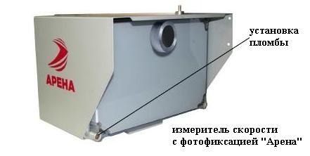
Передвижной комплекс Арена устанавливается на штатив сбоку от проезжей части под углом горизонтальной плоскости 25 градусов (боковая установка). В рабочий режим приводится быстро, за несколько минут.
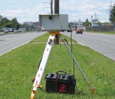
Стационарный вариант радара крепится сверху, над полосами движения, под тем же углом, но уже вертикальной плоскости (верхняя установка).
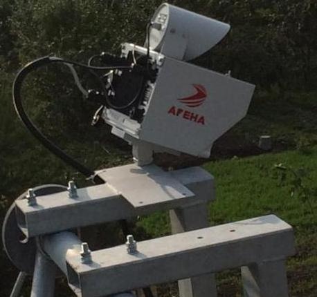
Камера работает автономно, без участия оператора, автоматически фиксируя превышение скорости в населенных пунктах, на автомагистралях. Зона действия прибора определяется геометрически, по варианту установки (боковому, верхнему).
Поверка производится по методике документа БКЮФ 2.788.140 МП, утвержденного ФГУП «ВНИИФТРИ» от 16.03.2006.
Функциональные возможности комплекса Арена
Радар контролирует движение автотранспорта на расстоянии до 1,5 км прямолинейно, в пределах прямой видимости. Камера работает в ночное время, вне зависимости от погодных условий. Зона действия распространяется на 3 полосы движения и всех участников движения, проезжающих через контролируемую зону.
Основной функционал комплекса Арена с фотофиксацией:
- оперативная установка, подготовка к работе;
- круглосуточное беспрерывное выполнение задач;
- фиксация транспортных средств, нарушающих скорость, распознавание их номеров в автоматическом режиме с точностью до 90 %;
- высокое качество фото, позволяющее различать черты лица водителя;
- определение координат места осуществления дорожного контроля;
- совмещение с центрами фиксации правонарушений.
Передвижной радар можно устанавливать не только на обочине, рядом с проезжей частью, но и на разделительной полосе. Оборудование статично, не поддается воздействиям при колебании воздуха, в том числе при движении автотранспорта. Комплекс достаточно предсказуем, способен автономно проверять работоспособность систем, степень готовности их к работе. Его надежность доказана на практике, поэтому его используют для контроля на дорогах не только в России, но и за ее пределами.
Особенности и принцип работы оборудования
Скорость транспортного средства в зоне действия камеры измеряет узколучевой радиолокационный модуль. Фиксация авто и распознавание его номера производится только при превышении скорости. Процесс измерения скорости основывается на эффекте Доплера. Замеряется разница между сигналом, который излучает измеритель, и сигналом, полученным от автомобиля, движущегося по контролируемой зоне.
ПО радарного комплекса Арена:
- Определяет, анализирует движение автотранспорта, проезжающего через контролируемую зону.
- Сравнивает зафиксированную скорость с установленным предельным значением.
- Выдает сигнал фотофиксации.
- Считывает, обрабатывает фото, отмечая дату, время, место фиксации, а также сведения об установленной, измеренной скорости.
- Сохраняет обработанную информацию на свой накопитель, отправляет ее на внешний компьютер.
Схема обнаружения, фиксации нарушителей ПДД, по сути, ординарная. Прибор замеряет скорость, сравнивает ее с предельным значением, которое записано в его установках. Если замер покажет превышение, камера Арена фотографирует автомобиль, указывая одновременно на фото дату, место фиксации, а также сведения о превышенной скорости.
Отличительные технические характеристики комплекса
Прибор весит до 8 кг, стандартные габариты 280 × 301 × 240 (длина, ширина, высота). Радар Арена замеряет скорость движения машин до 250 км/час. При этом погрешность измерений составляет плюс-минус 2 км/час.
Основные характеристики:
- диапазон измеряемой скорости — от 20 до 250 км/час;
- размер кадра (Кб) — до 200, объем архива (ГБ) на флеш-накопителе — до 5000;
- защита цифровых данных подписями;
- номинальное напряжение питания — 12 В;
- предельное питающее напряжение — от 11 до 16 В;
- мощность потребления — до 100 Вт;
- беспрерывная работа от заряженной аккумуляторной батареи — до 8 часов;
- функция автовыбраковки «спорных» кадров.
Радар работает при t от —40 до +50 градусов, относительной влажности воздуха 98 % (t = 25 градусов), атмосферном давлении 60–106,7 кПА. Производитель устанавливает средний срок эксплуатации для прибора 5 лет.
Комплексы фотовидеофиксации нарушений ПДД предназначены для контроля за дорожным движением в автоматическом режиме, фотофиксации событий, формирования материалов с последующей передачей в центр обработки данных.
Максимальная точность измерения скорости достигается благодаря использованию радиолокационных модулей собственной разработки.
Комплексы
|
Комплексы измерительные с фотофиксацией «ОРАКУЛ-ИНСАЙТ» |
m |
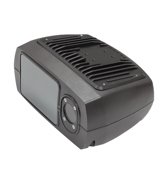
Один измеритель для трех вариантов применения
Варианты установки:
на объекты дорожной инфраструктуры
на приборную панель автомобиля
Измеряют скорость движения
транспортных средств
до 350 км/ч
Низкое энергопотребление
до 20 Вт
Количество контролируемых
полос движения
3
Легкий и компактный моноблок
Поверочное оборудование
Радиолокационные модули
|
Радиолокационный блок-модуль «РАПИРА-3D» |
m |
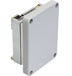
предназначен для работы в составе стационарных комплексов фотофиксации нарушений правил дорожного движения и адаптивных систем контроля и управления параметрами транспортных потоков.
Дополнительное оборудование
|
Графическое процессорное устройство «ГПУ-1» |
m |
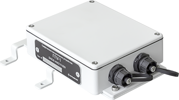
Графическое процессорное устройство «ГПУ-1» позволяет классифицировать транспортные средства (ТС) для автоматического изменения порога фиксации нарушений скоростного режима в зависимости от категории ТС.

ОСЬМИНОГ
Радиолокационный блок-модуль,
2013 год
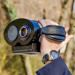
ВИЗИР 2М
Видеозаписывающий измеритель
скорости, 2009 год
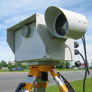
АРЕНА
Первый российский автоматический
комплекс фотофиксации, 2007 год
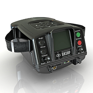
ВИЗИР
Переносной видеозаписывающий
измеритель скорости, 2006 год
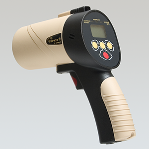
БЕРКУТ
Мобильный видеофиксатор,
2001 год
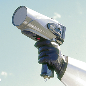
СОКОЛ
Первый российский ручной
измеритель скорости, 1997 год
Назначение
Описание
Программное обеспечение
Технические характеристики
Знак утверждения типа
Комплектность
Поверка
Сведения о методах измерений
Нормативные документы
Назначение
Измеритель скорости радиолокационный с фотофиксацией «АРЕНА» (далее по тексту -ИС) предназначен для автоматического измерения скорости и фотографирования движущихся транспортных средств (далее по тексту — ТС) на контролируемом участке дороги (далее по тексту — зона контроля).
Описание
ИС является радиолокационным прибором, принцип действия которого основан на измерении разности частот между сигналом, излученным ИС и сигналом, отраженным от находящегося в зоне контроля движущегося транспортного средства (эффект Доплера).
ИС измеряет скорость ТС, двигающегося в зоне контроля. Измеренное значение скорости ТС сравнивается с пороговым значением скорости, записанным в памяти ИС. При превышении измеренным значением скорости порогового значения, ИС производит фотографирование ТС с внесением в фотографию данных о его скорости, дате и времени фотографирования.
ИС предназначен для боковой или верхней установки:
• боковая установка — за пределами контролируемой проезжей части дороги под углом 25° между осью ИС и направлением движения ТС (угол в горизонтальной плоскости);
• верхняя установка — над полосой движения ТС, под углом 25° между осью ИС и направлением движения ТС (угол в вертикальной плоскости).
Параметры зоны контроля геометрически определяются способом установки ИС.
Конструктивно ИС выполнен в едином влагозащищенном и ударопрочном корпусе (степень защиты от воды и пыли IP65) с элементами крепления и содержит узколучевой радиолокационный модуль измерения скорости, цифровую камеру, модуль цифровой обработки и систему термостабилизации. На корпусе установлена шильда, содержащая наименование прибора, товарный знак изготовителя, знак утверждения типа средства измерения и заводской номер ИС. ИС опломбирован специальной пломбой, разрушающейся при попытке удаления.
Общий алгоритм работы ИС заключается в следующем. После въезда ТС в зону контроля, ИС производит измерение его скорости узколучевым радиолокационным измерительным модулем. При превышении установленного порога скорости ИС производит фотографирование ТС. Фотографирование ТС в зоне контроля аппаратно синхронизировано с сигналом узколучевого радиолокационного модуля измерения скорости. Соответствие измеренной скорости и ТС, изображенного на фотографии, обеспечивается механической юстировкой узколучевого радиолокационного модуля измерения скорости и цифровой камеры ИС в рамках моноблочной конструкции ИС.
Общий вид и способ пломбирования измерителя скорости радиолокационного с фотофиксацией «АРЕНА» представлен на рисунке 1:
>
Программное обеспечение
В функции, выполняемые программным обеспечением ИС входят:
• анализ отраженного сигнала, определение наличия движущейся цели, направления ее движения и значения ее скорости;
• сравнение измеренного значения скорости с пороговым и выдача сигнала фотографирования;
• считывание фотографии с цифровой камеры;
• обработка фотографии с внесением в кадр информации об измеренной скорости, текущей дате и времени, месте установки ИС, действующем ограничении скорости в месте установки и заводском номере ИС;
• сохранение полученных данных на внутренний носитель;
• передача информации на внешний компьютер;
• обеспечение внутренней термостабилизации и бесперебойной работы ИС;
• контроль входного питающего напряжения;
• прочие сервисные функции.
Таблица 1 — Идентификационные данные программного обеспечения ИС
|
Наименование программного обеспечения |
Идентифика ционное наименование программного обеспечения |
Номер версии (идентификационный номер) программного обеспечения |
Цифровой идентификатор программного обеспечения |
Алгоритм вычисления цифрового идентификатора |
|
АРЕНА-ИС |
A^LIENT |
6.5 |
3228 |
CRC16 |
Относительное отличие тестовых результатов вычислений от опорных (5): 0,007
Уровень защиты программного обеспечения от непреднамеренных и преднамеренных изменений «С» в соответствии с МИ 3286-2010.
Технические характеристики
Таблица 2
|
Рабочая частота излучения, ГГц |
24,15±0,1 |
|
Диапазон измерений скорости движения ТС, км/ч |
от 20 до 250 |
|
Пределы допускаемой абсолютной погрешности измерения скорости движения ТС, км/ч |
±2 |
|
Вид выходного кода |
двоичный |
|
Число разрядов кода (для представления измеренного значения скорости) |
8 |
|
Цена единицы наименьшего разряда кода, км/ч |
1 |
|
Номинальное напряжение питания, В |
12 |
|
Предельные значения питающего напряжения, В |
от 11 до 16 |
|
Мощность потребления при номинальном напряжении питания, не более, Вт |
100 |
|
Климатические условия применения: — температура окружающего воздуха, °С — относительная влажность воздуха при 25°С, % — атмосферное давление, мм рт. ст. |
от -40 до +50 98 от 630 до 800 (от 60 до 106,7 кПа) |
|
Средний срок службы, лет |
5 |
|
Средняя наработка на отказ, не менее, ч |
20000 |
|
Масса, не более, кг |
8 |
|
Габаритные размеры, не более, мм: длина ширина высота |
280 301 240 |
Знак утверждения типа
наносится фотохимическим способом на шильду, расположенную на корпусе измерителя скорости радиолокационного с фотофиксацией «АРЕНА», а также типографским или иным способом на титульный лист паспорта БКЮФ 2.788.140-01 ПС.
Комплектность
Таблица 3
|
Наименование |
Обозначение |
|
Измеритель скорости радиолокационный с фотофиксацией «АРЕНА» |
БКЮФ 2.788.140-06 |
|
Паспорт |
БКЮФ 2.788.140-01 ПС |
|
Методика поверки |
БКЮФ 2.788.140 МП |
Поверка
осуществляется по документу БКЮФ 2.788.140 МП «Измеритель скорости радиолокационный с фотофиксацией «АРЕНА». Методика поверки», утвержденному ГЦИ СИ ФГУП «ВНИИФТРИ» 16.03.2006 г.
Основные средства поверки:
— стенд автоматизированный для испытаний и поверки радиолокационных измерителей скорости «Сапсан 2» (погрешность измерения скорости ±0,1 км/ч).
Допускается применение аналогичных средств поверки, обеспечивающих определение метрологических характеристик поверяемых СИ с требуемой точностью.
Сведения о методах измерений
Метод измерений указан в паспорте на измеритель скорости с фотофиксацией «АРЕНА» БКЮФ 2.788.140-01 ПС.
Нормативные документы
ГОСТ Р 50856-96 Измерители скорости движения транспортных средств радиолокационные. Общие технические требования. Методы испытаний
Рекомендации МОЗМ МР-91 Измерение скорости транспортных средств радарными приборами
ГОСТ 8 129-2013 ГСИ Государственная поверочная схема для средств измерения времени и частоты
ГОСТ 12.1.006-84 ССБТ. Электромагнитные поля радиочастот. Общие требования безопасности
-
Contents
-
Table of Contents
-
Bookmarks
Quick Links
Related Manuals for Tannoy arena
Summary of Contents for Tannoy arena
-
Page 1
owners manual… -
Page 3: Table Of Contents
Tannoy will repair any such defect or, at our option, replace it without charge for parts, labour or return carriage. This warranty is given in addition to the customer’s statutory rights.
-
Page 4
UNPACKING Check the contents of the carton to identify the following items: 4 x satellite speakers 4 x satellite speaker grilles (with 2 x fixing screws each) three 1 x centre channel speaker four 1 x centre channel grille (with Hex fixing screw) five 20m speaker cable 1 x subwoofer… -
Page 5
three four five seven eight nine eleven twelve… -
Page 6
The time coherent, point source and constant directivity nature of the dispersion characteristics inherent in the Dual makes it an accepted industry standard in studio monitoring. By exceeding the rigorous demands of the recording and mastering environment Tannoy can ensure that playback performance in the home for multi channel home cinema, is strictly controlled to accurately reflect the sound engineers artistry. -
Page 8: Connections
CONNECTIONS Using the supplied twin core cable, connect each channel to the appropriate output of your AV receiver, observing polarity — positive to positive and negative to negative (or red to red and black to black). The supplied cable has the negative ( — ) core marked by a black line.
-
Page 9
CENTRE CHANNEL (C) FRONT RIGHT FRONT LEFT SATELLITE (F/R) SATELLITE (F/L) BLACK TERMINAL RED TERMINAL BLACK TERMINAL RED TERMINAL BLACK TERMINAL RED TERMINAL NEGATIVE (-) POSITIVE (+) NEGATIVE (-) POSITIVE (+) NEGATIVE (-) POSITIVE (+) SUBWOOFER (SUB) REAR RIGHT REAR LEFT SATELLITE (R/R) SATELLITE (R/L) BLACK TERMINAL… -
Page 10: Positioning
REAR shielded to avoid colour distortion Please consult your authorised to the television, but as some sets Tannoy dealer. are more sensitive to interference than others, some experimentation in placement may be required, or the use of the optional table stand to space the centre speaker further from the television.
-
Page 12: Grille Fixing
TRIM REMOVAL The Arena satellite and centre both have a removable front trim which gives the option of mixing and matching the speaker body colour with any of the optional trim colours.
-
Page 13
GRILLE FIXING TRIM REMOVAL… -
Page 14: Safety Instructions
IMPORTANT SAFETY INSTRUCTIONS — SUBWOOFER Read these instructions. Keep these instructions. Heed all warnings. Follow all instructions. Do not use this apparatus near water. Clean only with dry cloth. Do not block any ventilation openings. Install in accordance with manaufacturer’s instructions. Do not install near any heat sources such as radiators, heat registers, stoves, or other apparatus (including amplifiers) that produce heat.
-
Page 15
IMPORTANT SAFETY INSTRUCTIONS Electrical Requirements Check that the voltage rating displayed on the rear panel is correct for your area before connecting. If it is incorrect, please refer to your local dealer or authorised service agent, as no user adjustment is provided. EUROPEAN MODELS A mains cable is supplied with an IEC moulded socket at one end and a moulded mains plug at the other end. -
Page 16: Positioning And Fitting Of Feet
POSITIONING AND FITTING OF FEET As a subwoofer produces low frequencies only, it is difficult to detect its location by ear. It can therefore be placed anywhere in the room, but it is worth experimenting to find the optimum position. Bass output will increase next to a wall or especially in a corner; so use the volume control to compensate if moving your subwoofer around.
-
Page 17
for use on carpeted floors for use on polished floors… -
Page 18: Setting-Up
OVERLOAD PROTECTION The Arena subwoofer is provided with circuitry to limit the maximum sound output, in order to eliminate audible distortion. This circuitry will normally operate unnoticed. If however distortion is heard, this indicates the unit is being severely overloaded, and to avoid damage, the input level should be reduced immediately.
-
Page 19
1 ON / AUTO | 2 Phase (Degrees) | 3 LF Extension | 4 Volume | 5 LFE MODE | 6 Crossover (Hz) -
Page 20
Output Power 300W RMS Low Frequency Response (-6dB) 29Hz Limit for usable output 16Hz Input 1 x line level phono Input Filter order low pass, 50Hz – 150Hz, -6dB. Auto Mute After approximately 12 mins, in absence of input signal Driver Type 250mm (10”) Enclosure Type… -
Page 21
350.0mm ” 445.0mm ” 210.0mm ” INC. GRILLE 190.0mm 270.5mm ” ” EXC. GRILLE… -
Page 22: Satellites
Recommended amplifier power 15- 100W Sensitivity (2.83V @ 1m) 88dB Nominal impedance 8 ohm Frequency response (-6dB) 80Hz- 54kHz Crossover frequency 1.75kHz mid to high 80Hz to subwoofer Crossover type order low pass order high pass Dual Concentric Driver LF 100mm mixed fibre pulp cone Dynamic overload protection HF 19mm titanium dome with neodymium magnet system…
-
Page 23
175.5mm INC. GRILLE ” 133.5mm 164.5mm EXC. GRILLE ” ” 180.0mm 187.0mm ” ” EXC. GRILLE INC. GRILLE 149.0mm INC. GRILLE ” 245mm 138.0mm EXC. GRILLE ” ” 133mm ”… -
Page 24
1018.0mm ” 260.0mm 280.0mm ” 11”… -
Page 25
133.5mm ” 245.0mm ” 276.5mm ” 191.0mm ” 237.5mm INC. GRILLE 226.5mm INC. GRILLE ” ” 226.5mm EXC. GRILLE 215.5mm EXC. GRILLE ” ” 210.0mm 268.0mm ” ” 218mm INC. GRILLE ” 207.0mm EXC. GRILLE ” 229mm INC. GRILLE 9” 218.0mm EXC. -
Page 26
Centre Channel shown with optional stand mount Satellite shown with optional wall bracket… -
Page 27
Tannoy adopts a policy of continuous improvement and product specification is subject to change. E. & O.E. This equipment has undergone safety and EMC testing, and complies with the European Low Voltage Directive and Electromagnetic Compatibility Directive, together with the requirements of the Canadian Standards Association (CSA). -
Page 28
F: +44 (0) 1236 428230 E: enquiries@tannoy.com Tannoy North America T: (519) 745 1158 F: (519) 745 2364 E: inquiries@tannoyna.com Check periodically for the latest manual revision that will always available for download from www.tannoy.com The revision number of this manual is located below…
Главная » Видеорегистратор ARENA HD-900 » Инструкция по эксплуатации
Инструкция по эксплуатации:
| # | Описание файла | DL* | PP** | Скачать |
| * DL — download index/индекс загрузки ** PP — popularity index/индекс популярности |
||||
| Все файлы и ссылки на файлы, выложенные на сайте, были найдены в сети интернет как свободно распростроняемые и предоставлены лишь для ознакомления с ними. Если вы являетесь правообладателем какого либо контента и не желаете его свободного распространения, сообщите нам и нарушение будет устранено. Администрация сайта не несёт никакой ответственности за противоправные действия и какой либо ущерб, понесённый правообладателями. |
| Еще по теме: |
|
|