- Manuals
- Brands
- Datex-Ohmeda Manuals
- Medical Equipment
- CARESCAPE R860
- User’s reference manual
-
Contents
-
Table of Contents
-
Troubleshooting
-
Bookmarks
Related Manuals for Datex-Ohmeda CARESCAPE R860
Summary of Contents for Datex-Ohmeda CARESCAPE R860
-
Page 1
CARESCAPE™ R860 User’s Reference Manual Software Revision 10… -
Page 2
Datex-Ohmeda and by Datex-Ohmeda trained personnel. The Product must not be altered without the prior written approval of Datex-Ohmeda. The user of this Product shall have the sole responsibility for any malfunction which results from improper use, faulty maintenance, improper repair, damage, or alteration by anyone other than Datex-Ohmeda. -
Page 3: Table Of Contents
Table of Contents 1 Introduction Welcome ……..1-2 Indications for use/Intended use .
-
Page 4
™ CARESCAPE R860 4 Setup and connections General use and safety precautions ….4-3 Ventilator overview front ……4-5 Ventilator overview back . -
Page 5
Table of Contents Zeroing auxiliary pressure ….. . . 4-39 Connecting to a compressor ……4-40 Nurse call connection . -
Page 6
™ CARESCAPE R860 BiLevel airway pressure ventilation volume guaranteed (BiLevel VG) ……..5-28 Airway pressure release ventilation (APRV) . -
Page 7
Table of Contents Performing an Expiratory Hold ….. . . 7-8 Manual breath ……..7-9 Measuring P 0.1 . -
Page 8
™ CARESCAPE R860 O2 supply pressure low alarm test ….8-34 Air supply pressure low alarm test ….8-34 Sustained airway pressure (Paw) alarm test . -
Page 9
Table of Contents Review spontaneous breathing trial data … 10-3 Perform a spontaneous breathing trial … . . 10-3 Functional residual capacity view ….10-5 FRC procedures . -
Page 10
™ CARESCAPE R860 Factory default settings ……11-9 Service menus ……..11-12 Localization . -
Page 11
Table of Contents Manual disinfection ……12-23 Hydrogen peroxide ……12-23 Ortho-phthaldehyde . -
Page 12
™ CARESCAPE R860 Inspired pressure control ….. . .13-20 PEEP control ……. . 13-20 Oxygen-air mixture accuracy . -
Page 13
Table of Contents Oxygen consumption (VO2) ….. 14-8 Carbon dioxide production (VCO2) ….14-9 Respiratory quotient (RQ) . -
Page 14
™ CARESCAPE R860 17 Neonatal Introduction Overview of neonatal ventilation ….. 17-2 Neonatal manual ……17-2 18 Neonatal setup and connections General use and safety precautions . -
Page 15
Table of Contents Previous Patient ……20-4 Current Patient ……. 20-5 System Check . -
Page 16
™ CARESCAPE R860 Troubleshooting ……. . .22-28 nCPAP Troubleshooting ……22-30 General messages . -
Page 17
Table of Contents 24 Neonatal clinical decision support SBT view — Neonatal ……24-2 Perform a spontaneous breathing trial . -
Page 18
™ CARESCAPE R860 2065490-001… -
Page 19
1 Introduction Introduction In this section Welcome……..1-2 General information. -
Page 20: Welcome
Indications for use/Intended use The CARESCAPE R860 ventilator is designed to provide mechanical ventilation or support to neonatal, pediatric, and adult patients weighing 0.25 kg and above. The CARESCAPE R860 ventilator is a microprocessor based, electronically controlled, pneumatically driven ventilator that includes integrated monitoring of FiO2, airway pressure, flow, and volume.
-
Page 21: Trademarks
All other brand names or product names used in this manual are trademarks or registered trademarks of their respective holders. Serial numbers Datex-Ohmeda products have unit serial numbers with coded logic which indicates a product group code, the year of manufacture, and a sequential unit number for identification.
-
Page 22: General Information
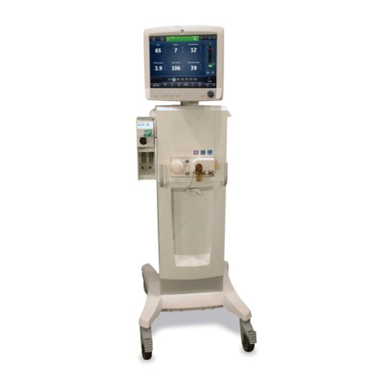
™ CARESCAPE R860 General information The CARESCAPE R860 combines sophisticated technology and an intuitive user interface. Icons represent configurable views of past (historical trends), present (patient status), and future patient needs (clinical decision support). The ventilator consists of a display, ventilator unit, cart with AC outlet (optional), EVair compressor (optional), and module bay with gas module (optional).
-
Page 23: Neonatal Manual
1 Introduction • BiLevel VG (BiLevel airway pressure ventilation Volume Guaranteed) • VS (Volume Support) • NIV (Non-Invasive Ventilation) • APRV (Airway Pressure Release Ventilation) Purchasable features: • FRC (Functional Residual Capacity) • SpiroDynamics Configurations available for this product depend on local market and standards requirements.
-
Page 24
2065490-001… -
Page 25
2 Symbols and abbreviations Symbols and abbreviations In this section Abbreviations……..2-2 Symbols, safety and manual terms. -
Page 26: Abbreviations
™ CARESCAPE R860 Abbreviations Abbreviation Definition AaDO2 Alveolar arterial oxygen gradient A/C PC Assist control pressure control A/C PRVC Assist control pressure regulated volume control A/C VC Assist control volume control APRV Airway pressure release ventilation BiLevel BiLevel airway pressure ventilation BiLevel VG BiLevel airway pressure ventilation volume guaranteed…
-
Page 27
2 Symbols and abbreviations mililiters MVexp Expired minute volume MVexp mech Expired minute volume per mechanical breath MVexp spont Expired minute volume per spontaneous breath MVexp/wt Expired minute volume per patient weight MVinsp Inspired minute volume nCPAP Nasal continuous positive airway pressure Neonatal Flow Sensor Negative inspiratory force Non-invasive ventilation… -
Page 28
™ CARESCAPE R860 Rate Respiratory rate Airway resistance Respiratory rate Respiratory quotient RSBI Rapid shallow breathing index SaO2 Arterial oxygen saturation level (of hemoglobin) Spontaneous breathing trial SIMV PC Synchronized intermittent mechanical ventilation pressure control SIMV PRVC Synchronized intermittent mandatory ventilation pressure regulated volume control SIMV VC Synchronized intermittent mechanical ventilation… -
Page 29: Symbols, Safety And Manual Terms
2 Symbols and abbreviations Symbols, safety and manual terms Read all user safety and manual instructions necessary to operate this device safely and in accordance with its functions and intended use. Symbols replace words on the equipment, the user interface (display), the packaging, or in the product manuals.
-
Page 30
Please contact an authorized Reference Manuals. The xxxx is the representative of the manufacturer for certification number of the Notified Body information concerning the used by Datex-Ohmeda’s Quality decommissioning of equipment. Systems. Authorized representative in the GOST R Russian certification… -
Page 31: Symbols On The User Interface
2 Symbols and abbreviations Non-ionizing electromagnetic radation MR unsafe MRI not compatible Standby Batch number Use-by date Autoclavable Not autoclavable Active alarm Eurasian conformity Ukraine national conformity Unique device identifier Symbols on the user interface Menu Adult patient type Pediatric patient type Neonatal patient type Start (green) Stop (red)
-
Page 32
™ CARESCAPE R860 Advanced Waveform view Spirometry view Future/Clinical Decision Support Measured values (numeric trends) view workspace Graphic trends view Ventilator calculations view Charting view FRC view FRC view (Brazilian Portuguese, Save metabolics data Portuguese, French) Pass (green) Fail (red) Metabolics view Splitscreen view SBT (Spontaneous Breathing Trial) view… -
Page 33: Symbols On The Packaging
2 Symbols and abbreviations Symbols on the packaging Humidity limitation Temperature limitation Do not stack Stacking limit by mass Fragile; handle with care Recyclable material Keep dry Protect from heat and radioactive sources This way up Atmospheric pressure limitation 2065490-001…
-
Page 34
2-10 2065490-001… -
Page 35
3 Navigation Navigation In this section Ventilator display……..3-2 Display user interface. -
Page 36: Ventilator Display
™ CARESCAPE R860 Ventilator display The 15-inch touchscreen display provides audible and visual alarms, integrated key pad, and a Trim Knob control. The display unit uses the Panasonic CR2477/BN battery (1000 mAh and 3V). To select menu options or settings, touch only one touch point at a time to make sure the correct selection is made.
-
Page 37
3 Navigation Figure 3-1 • Display controls and indicators Alarm light The integrated alarm light provides a visual alarm when an alarm condition occurs. The alarm light also provides a visual indicator when Audio Pause is active and alarm audio is silenced. Trim knob control Turn the Trim Knob clockwise or counterclockwise to change a setting. -
Page 38: Display User Interface
™ CARESCAPE R860 Display user interface The user interface incorporates the Menu, Current Patient menu, alarm management, and Favorites procedures at the top of the display. The patient status (airway pressure bar) and workspace/ monitoring area are located in the middle of the display. The navigation bar, message areas, battery status, standby, and quick keys are located at the bottom of the display.
-
Page 39: Navigating Active Alarms
3 Navigation Navigation Select an icon to open the corresponding view. See «Navigating the user interface» for detailed information. Additional Information Shows current time and additional setting information. Main power Indicates whether the ventilator is connected to the main power supply or is running on battery.
-
Page 40: Standby
™ CARESCAPE R860 Figure 3-3 • Select inside of the border to open the Alarm Setup menu. Standby Standby is displayed upon system startup or when the Standby quick key is selected. When the system is in Standby, the Standby quick key and the patient status (airway pressure) bar are colored tan.
-
Page 41: Main Menu
3 Navigation Figure 3-4 • Standby menu New Patient Select New Patient to enter patient information. Circuit Setup Select Circuit Setup to select HME or Humidifier for adult and pediatric patient types. Standby When Standby (hand icon) is selected the Standby menu displays. If the Patient detected alarm occurs, the Standby menu automatically displays.
-
Page 42: System Menu
™ CARESCAPE R860 Figure 3-5 • The main Menu accesses the System menu, Procedures, Lung Mechanics, Nebulizer, and Suction options. System Use the System menu to access data source, module type and version, calibrations (Paux Zero and Purge Flow), and display brightness. The System menu shows the software version, running hours, altitude, O2 supply pressure, air supply pressure, and battery status.
-
Page 43: Changing A Setting
3 Navigation The Airway Module type and software version number are shown under data source. Select Data Source (Ventilator or Airway Module). • For Neonatal; select Ventilator or NFS. See «System menu» in the «Neonatal Operation» section. Select Calibrations (Airway Module, Paux Zero, or Purge Flow).
-
Page 44
™ CARESCAPE R860 select the Home hard key, or wait for the selection to time out. For example, ventilation and alarm setting changes can be cleared by selecting the Home hard key prior to confirming a setting. 3-10 2065490-001… -
Page 45: Navigating The User Interface
3 Navigation Navigating the user interface The ventilator user interface uses three different workspaces: Past/ Historical trends, Present/Patient status, and Future/Clinical decision support. Each workspace (rectangle icon) contains views (circle icons) that contain different configurations of data and functions. When a workspace is selected, the correlating view icons are displayed.
-
Page 46: Present/Patient Status Workspace And Views
™ CARESCAPE R860 Present/Patient Status workspace and views The Present/Patient Status workspace shows the following views: Basic, Basic Waveform, Advanced Waveform, Splitscreen, and Charting. This workspace allows the user to choose the view in which they would like to see patient data displayed. See «Measured data definitions»…
-
Page 47
3 Navigation Basic Waveform View Use the Basic Waveform view to see patient waveforms and measured data. Note: the airway pressure bar may be collapsed to expand the monitoring area when the Paw and Flow waveforms are displayed. Advanced Waveform View Use the Advanced Waveform view to see additional measured data associated with the patient waveforms. -
Page 48
™ CARESCAPE R860 Charting View Use the Charting view to see a complete list of patient data.The airway pressure bar is permanently displayed to easily view patient airway and pressure settings, tidal volume and FiO2. 3-14 2065490-001… -
Page 49: Past/Historical Trends Workspace And Views
3 Navigation Past/Historical Trends workspace and views The Past/Historical trends workspace shows information for the following views: Graphical trends, Numerical trends, Trends log, and Snapshot trends. • Touch the icon to display the corresponding view. • Use a swipe gesture to view and move to Present/Patient status or Future/Clinical Decision Support workspaces.
-
Page 50
™ CARESCAPE R860 Trends Log View Use the Trends Log to review patient alarms and settings, and events that have occurred during ventilation. See «Trends log view» and «Trends log view — Neonatal» in the Patient Monitoring section. Snapshot Trends View Use Snapshot trends to view saved patient data. -
Page 51: Future/Clinical Decision Support Workspace And Views
3 Navigation Future/Clinical Decision Support workspace and views The Future/Clinical Decision Support workspace shows the following views (if software is installed): SBT, FRC, Spirometry, Metabolics, and Calculations. • Touch the view icon to display the corresponding view. • Use a swipe gesture to move to Present/Patient Status or Past/ HistoricalTrends workspaces and associated views.
-
Page 52
™ CARESCAPE R860 FRC View Use the FRC view to evaluate and review patient respiratory data. The FRC view includes three tabs: Evaluate, FRC INview (FRC procedure), and PEEP INview (PEEP INview procedure). See «FRC INview procedures» in the Clinical Decision Support section. -
Page 53
3 Navigation Calculations View Use the Calculations view to calculate and review data based on the ventilator, measured data, and laboratory blood gas analysis data. See «Calculations view» in the Clinical decision support section. 3-19 2065490-001… -
Page 54
3-20 2065490-001… -
Page 55: Setup And Connections
4 Setup and connections Setup and connections In this section General use and safety precautions….4-3 Ventilator overview front……4-5 Ventilator overview back.
-
Page 56
™ CARESCAPE R860 Communication port connection….. 4-43 IT network connection……4-45 Connecting isolated electrical outlets. -
Page 57: General Use And Safety Precautions
4 Setup and connections General use and safety precautions The following section describes the setup of the ventilator. Follow all safety precautions and warnings. WARNING Make sure system batteries are fully charged before use. It is recommended that the ventilator maintain connection to the main power supply at all times to prevent battery discharge and degradation.
-
Page 58
™ CARESCAPE R860 • The ventilator must not be used with helium or mixtures with helium. • A movable part or removable component may present a pinch or crush hazard. Use care when moving or replacing system parts and components. •… -
Page 59: Ventilator Overview Front
4 Setup and connections Ventilator overview front Menu Adult No Alarm s Ins p Manua l Hol d Hol d Breat h 14:3 8 Airwa y Pressur e FiO 2 PEEP e Peak Pressur e cmH2 O cmH2 O cmH2 O Pma x Ppea k Minute Volum e…
-
Page 60: Ventilator Overview Back
™ CARESCAPE R860 Ventilator overview back Figure 4-2 • Ventilator back view Note Not all connections may be available on all ventilator configurations. Ethernet connection (not supported) Air high-pressure inlet filter Ethernet connection (not supported) Air supply connection (pipeline) USB connection (not supported) Retaining channel USB connection (Service connection) Ventilator unit fan filter…
-
Page 61: Connecting Power
4 Setup and connections Connecting power The power cord is connected on the back of the ventilator as shown. The input power is less than 200 VA. Connect the power cord to the AC power outlet. Press the power switch to turn on the ventilator. •…
-
Page 62: Connecting And Removing The Exhalation Valve Housing
™ CARESCAPE R860 Connecting and removing the exhalation valve housing The exhalation valve housing contains the expiratory flow sensor and water trap. To attach the housing, place the tab (2) of the housing into the groove (1) and push the housing into position. •…
-
Page 63: Connecting Gas Supplies
4 Setup and connections Connecting gas supplies The O2 and air supply connections are located on the back of the ventilator. The air supply connection is on the left side and the O2 supply connection is on the right side as labeled on the ventilator. The ventilator comes with a standard air pipeline inlet assembly which includes a filter bowl, o-ring, and filter element.
-
Page 64: Connecting The Exhalation Valve Heater
™ CARESCAPE R860 Connecting the exhalation valve heater Use the exhalation valve heater to prevent moisture from condensing in the expiratory flow sensor when a humidifier is used. CAUTION Port 3 must only be used for connecting the exhalation valve heater cable. Important Order cable separately.
-
Page 65
4 Setup and connections Align and match the red dots from the exhalation valve heater cable to the power cable and snap together. Connecting the cable will power on the exhalation valve heater. Note To disconnect and remove the exhalation valve heater, follow instructions in reverse order. -
Page 66: Connecting The Accessory Rail
™ CARESCAPE R860 Connecting the accessory rail Lock the casters on the ventilator cart. Loosen the rail mount thumbscrew. • The wedge assembly on the rail is spring-loaded to allow rail installation into the dove-tail of the cart. Use the leading edge of the wedge assembly to insert the rail into the dovetail located on either side of the ventilator cart.
-
Page 67: Attaching System Accessories
4 Setup and connections • The rail adapter position can be adjusted by loosening the thumbscrew, sliding the rail adapter to the desired location, and then tightening the thumbscrew. Add accessories to the rail adapter. • Make sure the rail adapter is positioned correctly (thumbscrew down).
-
Page 68: Connecting The Breathing Circuit
™ CARESCAPE R860 Connecting the breathing circuit WARNING Do not use antistatic or electrically conductive breathing tubes or masks. • Check all connections to the breathing circuit to make sure that there are no unintended connections made to other equipment, especially equipment that delivers fluids, as the patient could be harmed.
-
Page 69: Connecting The Water Trap To The Breathing Circuit
4 Setup and connections Connecting the water trap to the breathing circuit Connect the patient circuit to the front port of the water trap housing. Connect the water trap connector tubing to the top port of the water trap housing. Connect the water trap connector tubing to the expiratory filter (if used) or expiratory port.
-
Page 70: Connecting A Hme (Heat And Moisture Exchanger)
™ CARESCAPE R860 Connecting a HME (heat and moisture exchanger) Note To prevent excessive resistance in the breathing circuit, the HMEF500 should not be used for Adult patients. Note If using optional accessories see Figure in «Connecting the Pedi- lite(+) and D-lite(+) sensors». Connect the inspiratory safety guard to the inspiratory port.
-
Page 71
4 Setup and connections Inspiratory safety guard Inspiratory limb Expiratory port/expiratory filter if used Expiratory limb Patient wye 4-17 2065490-001… -
Page 72: Connecting The Humidifier
™ CARESCAPE R860 Connecting the humidifier The ventilator is designed to work with active humidification. GE Healthcare recommends the use of the Fisher & Paykel MR850 humidifier (refer to humidifier instructions for detailed information on humidifier connections and use). WARNING Never position any filter in the inspiratory limb downstream of a humidifier.
-
Page 73
4 Setup and connections Menu Adult No Alarm s Ins p Manua l Hol d Hol d Breat h 14:3 8 Ai r way FiO 2 PEE Pe Peak P ressu re Pressu re cmH2 O cmH2 O cmH2 O Pma x Ppea k Minu te Volum e… -
Page 74: Connecting The Nebulizer
The CARESCAPE R860 supports the Aerogen Professional ® ® Nebulizer System (Aerogen Pro and Aerogen Solo).
-
Page 75: Disposable Nebulizer
4 Setup and connections Disposable nebulizer The Aerogen Solo nebulizer is a disposable nebulizer for single patient use. The Aerogen Solo can be used with neonatal, pediatric, and adult patients. The Solo nebulizer operates in-line like the Aerogen Pro, utilizing the ventilator nebulizer menu and nebulizer cable.
-
Page 76: Filling The Nebulizer
™ CARESCAPE R860 Complete a System Check prior to use on a patient. See «System Check» in the «Operation» section for additional information. Follow the «Nebulizer treatment» procedure in the «Procedures» section. Filling the nebulizer CAUTION To help avoid damage to the nebulizer, do not use a syringe with a needle.
-
Page 77: Disassembling The Nebulizer
4 Setup and connections Use a prefilled nebule or syringe to inject the medication into the filler port. Close the filler cap tab. Disassembling the nebulizer The nebulizer and T-adapter may remain in the patient circuit when not in use. The nebulizer may be removed from the T-adapter and replaced with a plug to avoid leaks.
-
Page 78: Functional Test
™ CARESCAPE R860 Functional test Perform a functional test of Aerogen nebulizers prior to first use, after each sterilization, before each patient use, or at any time to verify proper operation. Inspect all parts before use, and do not use if any parts are missing, cracked or damaged.
-
Page 79: Airway Modules
4 Setup and connections Airway modules Airway modules measure and monitor gases delivered to and from the patient. Airway modules have: • Nondispersive infrared technology to measure CO2, N2O, and anesthetic agents. • Paramagnetic technology to measure O2. The displayed FiO2 is adjusted by the ratio of the barometric pressure and 1.3 second moving average of the cyclic pressures obtained by the inspiratory pressure transducer.
-
Page 80: Compatible Airway Modules
™ CARESCAPE R860 Important The ventilator is not intended for use with anesthetic agents and does not measure or show anesthetic agent data. Compatible airway modules The following airway modules are compatible with the ventilator: • E-miniC • E-CO • E-COV •…
-
Page 81
4 Setup and connections E- series airway modules Figure 4-8 • E-series airway module D-fend water trap Gas sampling line connector on the water trap Water trap latch Reference gas inlet Gas sampling outlet Connectors for patient spirometry CARESCAPE airway modules Figure 4-9 •… -
Page 82: Connecting The Airway Module And Module Bay
™ CARESCAPE R860 D-fend water trap The airway module includes a single use D-fend water trap. The water trap has a hydrophobic membrane that prevents condensed water and secretions from entering the airway module measuring chamber. The condensed water and secretions are collected in a washable container.
-
Page 83
4 Setup and connections Figure 4-10 • Attaching and connecting the airway module bay Thumbscrew Excess cable Module bay connection Module bay cable Ventilator airway module bay connection Slide the airway module into the upper portion of the airway module bay. Attach the tubing to the airway module. -
Page 84: Connecting The Pedi-Lite(+) And D-Lite(+) Sensors
™ CARESCAPE R860 Connecting the Pedi-lite(+) and D-lite(+) sensors WARNING Use the Pedi-lite(+) sensor for patients with tidal volumes up to, and including 200 ml. • Use the D-lite(+) sensor for patients with tidal volumes greater than 200 ml. • To ensure patient safety, make sure that the gas sampling connectors are connected as described in these instructions and are not interchanged with…
-
Page 85: Airway Module Calibration
4 Setup and connections Figure 4-11 • Airway module connection to the patient breathing circuit Airway module Gas sample, gas sampling line connector on the water trap Gas sampling and spirometry tubes D-lite(+)/Pedi-lite(+) sensor Spacer (5 ml — minimum) Heat and moisture exchanger with filter (HMEF) (optional) Elbow Gas sampling line Note…
-
Page 86
™ CARESCAPE R860 Airway Module Calibration Gas E-miniC 755581-HEL E-CO 755587 (US only) E-COV E-COVX E-sCO E-sCOV E-sCOVX E-CAiO 755583-HEL E-CAiOV 755571-HEL (US only) E-CAiOVX E-sCAiO E-sCAiOV E-sCAiOVX 4-32 2065490-001… -
Page 87: Connecting The Support Arm
4 Setup and connections Connecting the support arm The support arm may be placed on either side of the ventilator to support the patient breathing circuit. To connect to the ventilator, place the post into the arm holder and tighten the thumbscrew. WARNING Do not exceed 2 kg load at the patient end of the support arm.
-
Page 88
™ CARESCAPE R860 Figure 4-12 • Support arm installation Thumbscrew Support arm holder Central tension handle 4-34 2065490-001… -
Page 89: Removing The Display Unit
4 Setup and connections Removing the display unit WARNING A movable part or a removable component may present a pinch or crush hazard. Use care when moving or replacing system parts and components. CAUTION The display unit is top heavy when removed from the ventilator.
-
Page 90: Installing The Display Unit On A Rail System
™ CARESCAPE R860 Installing the display unit on a rail system Use these instructions to install the display unit to a 10×25 mm, ISO 19054 rail system (medi-rail). Note Make sure that the display cable length is long enough to reach from the ventilator to the desired mounting location.
-
Page 91: Installing The Display Unit On The Ventilator
4 Setup and connections Installing the display unit on the ventilator Firmly hold the display unit at the junction of the display arm and display screen. Open the primary latch (1). Press and hold the secondary release latch (2) to disengage the display unit from the remote rail.
-
Page 92: Connecting The Auxiliary Pressure Tubing
™ CARESCAPE R860 Connecting the auxiliary pressure tubing Auxiliary pressure is a supplementary pressure measurement that can be displayed with a waveform and patient data (measured data). Attach the auxilliary pressure tubing to the Paux port by sliding the tubing over the barbed end of the port. Figure 4-16 •…
-
Page 93: Zeroing Auxiliary Pressure
4 Setup and connections Purge Flow will automatically turn off if auxiliary pressure becomes greater than 100 cmH2O to prevent overpressuring the tubing. Reconnect the patient end of the tubing. Zeroing auxiliary pressure Auxiliary pressure measurements and waveforms will be more accurate if the pressure is zeroed before use.
-
Page 94: Connecting To A Compressor
™ CARESCAPE R860 Connecting to a compressor The EVair compressor can be connected to the ventilator and used as the primary air supply or as the backup air supply if pipeline air is connected to the compressor. See the EVair User Reference Manual and Technical Reference Manual for additional information.
-
Page 95: Nurse Call Connection
4 Setup and connections Nurse call connection WARNING The ventilator should be used as the primary source of alarm information and awareness of alarm activity. • User must rely on the ventilator primary displays and controls for ventilation therapy decisions. •…
-
Page 96
™ CARESCAPE R860 Load current: • minimum: 100 uA at 100 mVdc • maximum: 1 A at 30 Vdc • relay isolated 4-42 2065490-001… -
Page 97: Communication Port Connection
The 9 pin connectors are located on the back of the display unit and are labeled port 5 and port 6. The output protocol is available at www.datex-ohmeda.com (under Products/ Interfacing Commitment Products) or by contacting GE Healthcare at InterfaceCommitment@ge.com.
-
Page 98
™ CARESCAPE R860 • Pin 2 — display unit receive • Pin 3 — display unit transmit • Pin 5 — ISO ground • All other pins are not connected 4-44 2065490-001… -
Page 99: It Network Connection
Datex- Ohmeda Com 1.3, 1.5, and 1.7 Serial Protocol. Information on the Datex-Ohmeda Com protocols are available by contacting Technical Support. The output protocol is available at www.datex-ohmeda.com (under Products/Interfacing Commitment Products) or by contacting GE Healthcare.
-
Page 100: Connecting Isolated Electrical Outlets
™ CARESCAPE R860 Connecting isolated electrical outlets The configuration of the electrical outlets varies by country. WARNING Do not overload the electrical outlets. Maximum permitted load for each output socket in the electrical outlet panel: Voltage Current 100 to 120 V 220 to 240 V 4-46 2065490-001…
-
Page 101: Ventilation Modes
5 Ventilation modes Ventilation modes In this section Ventilation mode basics……5-2 Ventilation mode features……5-9 Assist control volume control (A/C VC).
-
Page 102: Ventilation Mode Basics
™ CARESCAPE R860 Ventilation mode basics Invasive and non-invasive ventilation The ventilator provides several standard modes for invasive ventilation and non-invasive modes (nCPAP for neonates). • Invasive ventilation modes provide a range of patient support, from fully controlled mechanical breaths to pressure supported breaths for spontaneously breathing patients.
-
Page 103: Ventilation Mode Settings
5 Ventilation modes Note In ventilation modes with a PS setting, spontaneous breaths are pressure-supported at the PS level. Figure 5-1 • Breath Types Patient-initiated, mechanical breath Spontaneous pressure supported breath Ventilator-initiated, mechanical breath Note The segment colored orange in the waveform represents the breath trigger.
-
Page 104
™ CARESCAPE R860 • When the setting is less than the minimum value of the new numeric range, the minimum value is set. • When the setting is between increments, the value is rounded to the increment above or below it. Main Parameter Definition FiO2… -
Page 105: Positive End Expiratory Pressure (Peep)
5 Ventilation modes Breath Timing Definition Tlow Low Time The time in seconds that the ventilator holds the low pressure level in APRV mode. Patient Synchrony Definition Insp Trigger Inspiratory Trigger The patient effort required to initiate the inspiratory phase of a breath. The trigger can be set as either a positive flow value (Flow Trigger) or a negative pressure deflection below PEEP (Pressure Trigger).
-
Page 106: Pressure Support
™ CARESCAPE R860 Pressure support Pressure support provides additional pressure during the inspiratory phase of spontaneous breaths in spontaneous breathing modes. The PS setting is available in the following ventilation modes: • CPAP/PS • SIMV VC • SIMV PC • SIMV PRVC •…
-
Page 107: Breath Timing Preferences
5 Ventilation modes • BiLevel • BiLevel VG And when assist control is active in the following modes: • A/C VC • A/C PC • A/C PRVC Breath timing preferences The parameters used to represent the timing of a delivered breath or inspiratory phase of a delivered breath may be selected by the facility.
-
Page 108
™ CARESCAPE R860 Note Selecting a breath timing for the modes listed in the table will not affect other ventilation modes. 2065490-001… -
Page 109: Ventilation Mode Features
5 Ventilation modes Ventilation mode features Tube compensation When a patient is intubated, the endotracheal or tracheostomy tube creates resistance in the airway. Tube compensation provides additional pressure to compensate for the difference between the lung pressure and breathing circuit pressure during the inspiratory phase of pressure-controlled and pressure-supported breaths.
-
Page 110: Leak Compensation
™ CARESCAPE R860 A general message shows when assist control is off. When assist control is off, the patient is able to draw spontaneous breaths at the set PEEP level between mechanical breaths. To set Assist Control, select Current Mode > Mode Settings and select Assist Control (On or Off).
-
Page 111: Backup Mode
5 Ventilation modes Backup mode Backup mode is available if the ventilator detects insufficient ventilation in modes that allow spontaneous breaths. When enabled, the ventilator automatically enters the set Backup mode if either of the following occur: • The Apnea alarm is activated. •…
-
Page 112: Assist Control Volume Control (A/C Vc)
™ CARESCAPE R860 Assist control volume control (A/C VC) During A/C VC mode, the ventilator delivers mechanical breaths of the set tidal volume (VT) at intervals based on the set respiratory rate (Rate). Note The amount of pressure required to deliver the tidal volume depends on the patient’s lung compliance and resistance.
-
Page 113
5 Ventilation modes Figure 5-2 • A/C VC Waveforms Airway pressure (Paw) waveform Inspiratory time (Tinsp) Inspiratory pause (Tpause) Expiratory time (Texp) PEEP Flow waveform Tidal volume (VT) 5-13 2065490-001… -
Page 114: Assist Control Pressure Control (A/C Pc)
™ CARESCAPE R860 Assist control pressure control (A/C PC) During A/C PC mode, the ventilator delivers mechanical breaths at the set inspiratory pressure level (Pinsp) for a set inspiratory time (Tinsp) at intervals based on the set respiratory rate (Rate). Note The tidal volume delivered depends on the compliance of the patient’s lungs.
-
Page 115
5 Ventilation modes Figure 5-3 • A/C PC waveforms Airway pressure (Paw) waveform Inspiratory time (Tinsp) Expiratory time (Texp) Inspiratory pressure (Pinsp) PEEP Flow waveform Tidal Volume (VT) 5-15 2065490-001… -
Page 116: Assist Control Pressure Regulated Volume Control
™ CARESCAPE R860 Assist control pressure regulated volume control (A/C PRVC) During A/C PRVC mode, the ventilator delivers mechanical breaths of the set tidal volume (VT) at intervals based on the set respiratory rate (Rate). For each breath, the ventilator adjusts the inspiratory pressure to use the lowest pressure required to deliver the tidal volume.
-
Page 117
5 Ventilation modes Category Setting Safety Pmax Pmin Figure 5-4 • A/C PRVC waveforms Airway pressure (Paw) waveform Inspiratory time (Tinsp) Expiratory time (Texp) Variable pressure to deliver set TV PEEP Flow waveform Tidal volume (VT) 5-17 2065490-001… -
Page 118: Synchronized Intermittent Mandatory Ventilation Volume
™ CARESCAPE R860 Synchronized intermittent mandatory ventilation volume control (SIMV VC) During SIMV VC mode, the ventilator delivers synchronized volume- controlled breaths at the set respiratory rate (Rate). All other spontaneous efforts are delivered as pressure-supported breaths. Note Actual ventilation settings may be different if breath timing settings (Timing and Flow) have been changed.
-
Page 119
5 Ventilation modes Figure 5-5 • SIMV VC waveforms Airway pressure (Paw) waveform Inspiratory time (Tinsp) Inspiratory pause (Insp Pause) Spontaneous breathing period Pressure-supported breath Flow waveform Tidal volume (VT) PEEP Trigger window 5-19 2065490-001… -
Page 120: Synchronized Intermittent Mandatory Ventilation Pressure
™ CARESCAPE R860 Synchronized intermittent mandatory ventilation pressure control (SIMV PC) During SIMV PC mode, the ventilator delivers synchronized pressure-controlled breaths, the number of which is determined by the set respiratory rate (Rate). All other spontaneous efforts are delivered as pressure-supported breaths. Note Backup ventilation is available in SIMV PC mode.
-
Page 121
5 Ventilation modes Airway pressure (Paw) waveform Inspiratory time (Tinsp) Spontaneous breathing time Pressure-supported breath Inspiratory pressure (Pinsp) Flow waveform Trigger window PEEP Tidal Volume (VT) 5-21 2065490-001… -
Page 122: Synchronized Intermittent Mandatory Ventilation Pressure Regulated Volume Control (Simv Prvc)
™ CARESCAPE R860 Synchronized intermittent mandatory ventilation pressure regulated volume control (SIMV PRVC) Note SIMV PRVC mode is a purchasable option. During SIMV PRVC mode, the ventilator delivers synchronized pressure regulated volume controlled breaths at the set respiratory rate (Rate). For each mechanical breath, the ventilator adjusts the inspiratory pressure to use the lowest pressure required to deliver the tidal volume.
-
Page 123
5 Ventilation modes Category Setting Patient Synchrony Insp Trigger Exp Trigger Bias Flow PS Rise Time Rise Time Safety Pmax Pmin Figure 5-7 • SIMV PRVC waveform Airway pressure (Paw) waveform Inspiratory time (Tinsp) Spontaneous breathing time Variable pressure PEEP Flow waveform Tidal volume (VT) Pressure supported breath… -
Page 124: Continuous Positive Airway Pressure / Pressure Support
™ CARESCAPE R860 Continuous positive airway pressure / pressure support (CPAP/PS) CPAP/PS mode is intended to be used on spontaneously breathing patients. During CPAP/PS mode, the ventilator maintains a PEEP level and provides pressure support (PS). The patient initiates spontaneous breaths and determines respiratory rate, timing, and tidal volume.
-
Page 125
5 Ventilation modes Figure 5-8 • CPAP/PS waveforms Airway pressure (Paw) waveform Pressure support (PS) Inspiratory time (Backup Tinsp) PEEP Flow waveform Backup Pinsp Minimum rate backup breath Tidal Volume (TV) 5-25 2065490-001… -
Page 126: Bilevel Airway Pressure Ventilation (Bilevel)
™ CARESCAPE R860 BiLevel airway pressure ventilation (BiLevel) Note BiLevel mode is a purchasable option. During BiLevel mode, the ventilator alternates between the set PEEP level and the set inspiratory pressure level (Pinsp) based on the set Rate and Tinsp. The patient can breathe spontaneously at either level.
-
Page 127
5 Ventilation modes Figure 5-9 • BiLevel waveforms Airway pressure (Paw) waveform Tinsp Exp time Pressure Support (PS) Pinsp PEEP Flow waveform Tidal Volume (VT) 5-27 2065490-001… -
Page 128: Bilevel Airway Pressure Ventilation Volume Guaranteed
™ CARESCAPE R860 BiLevel airway pressure ventilation volume guaranteed (BiLevel VG) Note BiLevel VG mode is a purchasable option. During BiLevel VG mode, if the patient initiates a breath at the PEEP level, a pressure-supported breath at the PS setting is delivered. The ventilator alternates between a set PEEP and the minimum pressure to deliver the set tidal volume (VT) based on the set Rate and Tinsp.
-
Page 129
5 Ventilation modes Category Setting Safety Pmax Pmin Figure 5-10 • BiLevel VG waveforms Airway pressure (Paw) waveform Inspiratory time (Tinsp) Spontaneous breathing period Trigger window Variable pressure Flow waveform Tidal volume (VT) Pressure-supported breath PEEP 5-29 2065490-001… -
Page 130: Airway Pressure Release Ventilation (Aprv)
™ CARESCAPE R860 Airway pressure release ventilation (APRV) Note APRV mode is a purchasable option. APRV mode is intended to be used on spontaneously breathing patients. During APRV mode, the ventilator alternates between a set high (Phigh) and low (Plow) pressure level. The ventilator will deliver the set (Phigh) pressure for the set (Thigh) duration of time.
-
Page 131
5 Ventilation modes Airway pressure (Paw) waveform Thigh Tlow Phigh Plow Flow waveform 5-31 2065490-001… -
Page 132: Volume Support (Vs)
™ CARESCAPE R860 Volume Support (VS) Note VS mode is a purchasable option. VS mode is intended to be used on spontaneously breathing patients. During VS, the patient initiates spontaneous breaths and determines respiratory rate and timing. The ventilator maintains a PEEP level and provides support to deliver the set tidal volume (VT).
-
Page 133
5 Ventilation modes Category Setting Safety Pmax Pmin Minimum Rate Backup Tinsp Figure 5-12 • VS waveforms Airway pressure (Paw) waveform Spontaneous inspiratory time Spontaneous breathing period Variable pressure PEEP Flow waveform Tidal Volume (VT) Inspiratory time (Backup Tinsp) Backup Pinsp Minimum rate backup breath 5-33 2065490-001… -
Page 134: Non-Invasive Ventilation (Niv)
™ CARESCAPE R860 Non-invasive ventilation (NIV) Note NIV mode is a purchasable option. NIV mode is intended to be used on spontaneously breathing patients. During NIV mode, the patient draws spontaneous breaths as the ventilator maintains the set PEEP level and provides pressure support (PS).
-
Page 135
5 Ventilation modes Category Setting Patient Synchrony Tsupp Insp Trigger Exp Trigger Bias Flow Rise Time Safety PMax Backup Pinsp Minimum Rate Backup Tinsp WARNING Before using NIV mode, the patient should demonstrate all of the following characteristics: • Is responsive •… -
Page 136
™ CARESCAPE R860 Backup Pinsp Minimum rate backup breath Tidal Volume (VT) 5-36 2065490-001… -
Page 137: Spontaneous Breathing Trial (Sbt Mode)
5 Ventilation modes Spontaneous breathing trial (SBT mode) SBT mode is intended to be used as a part of the procedure to evaluate the patient’s ability to breathe spontaneously during a specified duration of time. See «SBT view» in the «Clinical decision support»…
-
Page 138
™ CARESCAPE R860 Figure 5-14 • SBT waveforms Airway pressure (Paw) waveform Pressure support (PS) PEEP Flow waveform Tidal Volume (VT) 5-38 2065490-001… -
Page 139: Operation
6 Operation Operation In this section Power……… . 6-2 Patient Setup.
-
Page 140: Power
™ CARESCAPE R860 Power Turning on power to the ventilator Plug the power cord into an electrical outlet. • The LED indicator illuminates (green) to indicate the main power is connected. Press the power switch on the back of the ventilator to the On position.
-
Page 141
6 Operation Select Pause Ventilation. • Monitoring and ventilation will stop. Press the power switch on the back of the ventilator to the Off position. 2065490-001… -
Page 142: Patient Setup
™ CARESCAPE R860 Patient Setup New Patient Use these instructions for preparing the ventilator for a New Patient. After powering on the ventilator the Standby menu displays. Select NEW PATIENT. Select Adult, Pediatric, or Neonatal patient type. Select Patient ID (identification). •…
-
Page 143: Current Patient
6 Operation From the Standby menu, select PREVIOUS PATIENT. Important Previous Patient data is only saved when a normal shutdown sequence is performed. Abrupt or unexpected power loss will prevent this data from being saved. Current Patient Use this menu to update settings or change patient type from Pediatric to Adult or Adult to Pediatric.
-
Page 144: System Check
™ CARESCAPE R860 System Check System Check overview The ventilator should be fully cleaned and prepared for a patient before performing the System Check. When started, the System Check runs automatically. Selecting the information icon will show the active progress in the System Check Details menu.
-
Page 145: Circuit Setup
6 Operation • If the relief valve failure alarm activates after the System Check then the ventilator will not allow ventilation until the relief valve portion of the System Check has passed. Circuit Setup Use the Circuit Setup menu to select settings that must be compensated for in patient circuit measurements.
-
Page 146
™ CARESCAPE R860 Occlude the patient wye using the occlusion port. INSP Occlusion port Select Start. The System Check starts and shows the results of each check. The system runs the following checks: • Paw transducer check • Barometric pressure check •… -
Page 147
6 Operation When the System Check is complete, the Final Result line will display the patient type icon, a green check mark (pass) or red X (fail), and the date and time of the System Check. 2065490-001… -
Page 148: Patient Ventilation
™ CARESCAPE R860 Patient ventilation Setting the ventilator data source The data source is used to obtain patient monitoring parameters from either the ventilator or the airway module. See «Patient monitoring» for detailed information. See «Setting the ventilator data source»in the «Neonatal Operation» section. Select Menu >…
-
Page 149: Setting A Ventilation And Backup Mode
6 Operation The Airway Module type and software version number are shown under data source. Select Data Source (Ventilator or Airway Module). • For Neonatal; select Ventilator or NFS. See «System menu» in the «Neonatal Operation» section. Select Calibrations (Airway Module, Paux Zero, or Purge Flow).
-
Page 150: Starting Patient Ventilation
™ CARESCAPE R860 icon represents the facility’s set ventilation modes and the full list icon represents the full set of ventilation modes available. Select the appropriate icon to see available ventilation modes. Partial list of ventilator modes Full list of ventilator modes Select Assist Control, Leak Comp, or Trigger Comp if desired.
-
Page 151: Pausing Ventilation
6 Operation If the Start Ventilation button is yellow, the Complete System Check warning alert will display the following: Select Continue to bypass System Checkout and start ventilation. Select Cancel to remain in Standby. Note It is recommended that System Check is completed prior to starting ventilation.
-
Page 152: Setting Favorites
™ CARESCAPE R860 INSP Occlusion port Select PARK CIRCUIT. • The display will show: Patient circuit is occluded and the ventilator is in Standby. Setting Favorites Up to four Favorite procedures may be selected to show on the upper-right corner of the user interface. Select Menu.
-
Page 153: Procedures
7 Procedures Procedures In this section Suction……… 7-2 Nebulizer treatment.
-
Page 154: Suction
™ CARESCAPE R860 Suction Closed Suction: Any ventilation modes and settings may be used with a closed suction catheter. Patient Disconnected, RR low, MVexp low, VTexp low, Apnea, and other alarms may occur during use of a closed suction catheter. Open Suction: To perform suctioning without nuisance alarms, an open suction procedure is provided by the ventilator.
-
Page 155: Nebulizer Treatment
7 Procedures Nebulizer treatment ® The Aerogen Professional Nebulizer System is a portable medical device that is intended to aerosolize physician-prescribed solutions and suspensions for inhalation to patients on and off ventilation or other positive pressure breathing assistance. The ventilator supports the Aerogen Pro and Aerogen Solo (disposable) in-line nebulizers by Aerogen.
-
Page 156
™ CARESCAPE R860 average nebulization rate of 0.38 ml/min, but the actual nebulization rate of each individual nebulizer cannot be guaranteed and may vary significantly Time (min) Volume (ml) 10.0 12.0 Select Start. Note To end a nebulizer treatment before the set time, select Stop. 2065490-001… -
Page 157: Pneumatic Nebulizer
7 Procedures Pneumatic nebulizer The ventilator can compensate for additional flow introduced by a pneumatic nebulizer into the patient circuit. The displayed FiO2 measurement does not reflect the additional gas introduced to the patient through the nebulizer. WARNING Use of an external pneumatic nebulizer may significantly modify the mixture of gas that is delivered to the patient.
-
Page 158: Performing An Increase O2 Procedure
™ CARESCAPE R860 Performing an Increase O2 procedure Increase O2 is used to increase the amount of oxygen delivered to the patient to prevent low oxygen saturation levels. Select as a Favorite (the procedure will start immediately — see «Setting Favorites» in the Operation section), or select Menu > Procedures >…
-
Page 159: Performing An Inspiratory Hold
7 Procedures Performing an Inspiratory Hold The Inspiratory Hold procedure may be used during an x-ray procedure or to determine plateau pressure and static compliance calculations. When Inspiratory Hold is selected the inspiratory and expiratory valves close at the end of the next inspiratory phase. The Inspiratory Hold cannot be repeated until the patient triggers a spontaneous breath or the ventilator delivers a mandatory breath.
-
Page 160: Performing An Expiratory Hold
™ CARESCAPE R860 Performing an Expiratory Hold The Expiratory Hold procedure is used to measure the end breath lung pressure. When Expiratory Hold is selected, the inspiratory and expiratory valves close at the end of the next expiratory phase. The expiratory hold cannot be repeated until the patient triggers a spontaneous breath or the ventilator delivers a mandatory breath.
-
Page 161: Manual Breath
7 Procedures Manual breath The Manual Breath procedure allows the clinician to deliver additional mechanical breaths to the patient. The ventilator requires a 0.25 second pause between delivery of breaths. The breath delivered is based on the settings for the current mode or backup ventilation mode if a rate is not set for the current mode.
-
Page 162: Measuring P 0.1
™ CARESCAPE R860 Measuring P 0.1 P 0.1 is a respiratory measurement used to evaluate the patient’s readiness to be weaned from the ventilator. P 0.1 is a measurement of the airway occlusion pressure 0.1 second after beginning an inspiratory effort against an occluded airway. Select as a Favorite.
-
Page 163: Measuring Negative Inspiratory Force (Nif)
7 Procedures Measuring Negative Inspiratory Force (NIF) Negative Inspiratory Force is a weaning measurement that is used to evaluate the patient’s readiness to be weaned from the ventilator. NIF is used to determine the patient’s ability to take a deep breath and to generate a cough strong enough to clear secretions.
-
Page 164: Measuring Vital Capacity
™ CARESCAPE R860 Measuring Vital capacity Vital Capacity is the measurement of a patient’s largest (VTexp) expired Tidal Volume over a 30 second period. During a Vital Capacity measurement, Pinsp and PS are set to zero. When the Vital Capacity measurement is complete Pinsp and PS return to the previous setting.
-
Page 165: Measuring Auto Peep
7 Procedures Measuring Auto PEEP Auto PEEP or Intrinsic PEEP is a measurement of pressure remaining in the lungs above the PEEP value at the end of a breath. It may be used as an indication of a patient’s inability to completely exhale.
-
Page 166
7-14 2065490-001… -
Page 167: Alarms And Troubleshooting
8 Alarms and troubleshooting Alarms and troubleshooting In this section Alarms……… . 8-2 Alarm management.
-
Page 168: Alarms
™ CARESCAPE R860 Alarms WARNING If an alarm occurs, attend to the patient before troubleshooting or doing any repair procedures. • A hazard can exist if different alarm settings are used for the same parameter for similar equipment in any single area, such as an intensive care unit.
-
Page 169: Alarm Management
8 Alarms and troubleshooting Alarm management During ventilation, alarms are managed from the alarm bar, which gives a visual indication of the priority and type of alarm. Use the alarm bar to acknowledge alarms and access alarm settings. When a parameter alarm occurs, the measured data can be selected to quickly access the setting that is out of range.
-
Page 170: Alarm Setup
™ CARESCAPE R860 Figure 8-2 • Alarm count Audio pause timer Active alarm count Adjacent to Alarms is a number that shows how many alarms are in the list. Select the alarm status to show the list of alarm messages. The alarm messages are in the order of when the alarm occurred, with the most recent alarm shown at the top of the list.
-
Page 171
8 Alarms and troubleshooting • Patient Effort (NIV mode only) • Tdisconnect (NIV mode only) Figure 8-3 • Alarm setup menu Note Alarm limits for EtCO2, EtO2, and PEEPi are only available when an airway module with these measurement capabilities is installed. If the patient type is Neonatal, these alarm limits are not shown. -
Page 172: Auto Limits
™ CARESCAPE R860 Alarm Limits Select the check box to show alarm limits adjacent to the measured data in Basic, Basic Waveforms, Advanced Waveforms, and Splitscreen views. The alarm limit always shows when an alarm occurs for the measured data, even if it is set to Off. Auto Limits Select to set auto alarm limits based on current measured data.
-
Page 173: Audio Pause
8 Alarms and troubleshooting Priority Color Light Tone High Flashes red Series of five tones, twice Medium Yellow Flashes yellow Series of three tones Blue Solid blue Single tone Note For medium and high priority alarms, the alarm tone is repeated until audio pause is selected or the alarm condition is resolved.
-
Page 174: Secondary Audio Alarm
™ CARESCAPE R860 • Sustained airway pressure • System shutdown in less than 20 (10, 5, and 1) minutes • Power supply error Audio pause will not mute the alarm tone for the folowing alarms: • Patient detected • Turn off ventilator? Secondary audio alarm If the primary audio alarm fails, the ventilator has a secondary audio alarm as a backup.
-
Page 175: List Of Alarms — Adult And Pediatric
8 Alarms and troubleshooting List of alarms — adult and pediatric Important If the patient type is Neonatal, see «List of alarms – Neonatal» for details. Note See Alarms and Troubleshooting and Alarm Tests for additional information about alarms and to see a list of general messages. These notes apply to the alarm messages in the table below: •…
-
Page 176
™ CARESCAPE R860 Alarm Priority Condition* Cause Action Airway module Medium There is a problem with The airway module is not • Replace the airway error the installed airway working. CO2 and O2 module. module. Airway module data are not available. spirometry data is not The airway module data available while this alarm… -
Page 177
8 Alarms and troubleshooting Alarm Priority Condition* Cause Action Airway module High Peak pressure measured The airway module does • Install the airway module sensor error by the airway module is not detect pressure or spirometry sensor below 3 cmH2O, and is flow. -
Page 178
™ CARESCAPE R860 Alarm Priority Condition* Cause Action Backup Medium Apnea has been detected. Apnea detected. • Check the status of the ventilation on patient. • Review the ventilator settings. • Confirm the current mode in Mode Settings to continue using backup ventilation settings. -
Page 179
8 Alarms and troubleshooting Alarm Priority Condition* Cause Action Battery error Medium Battery power is not Battery power is not • Contact an authorized available due to one of available. Ventilation will service representative. the following issues: stop if main power supply is lost. -
Page 180
™ CARESCAPE R860 Alarm Priority Condition* Cause Action Cooling fan error High A power system Ventilator is overheating. • Clean the ventilator unit component has Ventilation may stop. fan filter. overheated. • Contact an authorized service representative. Medium There is a problem with The system detected a •… -
Page 181
8 Alarms and troubleshooting Alarm Priority Condition* Cause Action EtO2 high Medium End tidal O2 measured by End tidal O2 is greater • Check for additional O2 the airway module is than the high alarm limit. flow into the patient greater than the EtO2 circuit. -
Page 182
™ CARESCAPE R860 Alarm Priority Condition* Cause Action FiO2 high High Measured FiO2% is Inspired O2 is greater • Check for additional O2 higher than the FiO2 high than the high alarm limit. flow into the patient alarm limit. circuit. •… -
Page 183
8 Alarms and troubleshooting Alarm Priority Condition* Cause Action Another procedure or The FiO2 setting was • Set FRC O2 to be a condition prevented the changed between FRC minimum of 10% higher FRC series measurement measurements. At least or lower than the FiO2 from starting within the a 10% difference must setting, and then start the… -
Page 184
™ CARESCAPE R860 Alarm Priority Condition* Cause Action MVexp high High Measured expired minute Expired minute volume • Check the status of the volume is greater than the is greater than the high patient. MVexp high alarm limit. alarm limit. •… -
Page 185
8 Alarms and troubleshooting Alarm Priority Condition* Cause Action O2 supply O2 supply pressure The ventilator is not able • Perform System Check. pressure sensor sensor data is invalid to measure O2 supply • Contact an authorized error while not in therapy. pressure. -
Page 186
™ CARESCAPE R860 Alarm Priority Condition* Cause Action Paux sensor error Low Auxiliary pressure sensor The ventilator is not able • Remove the auxiliary data is invalid. to measure auxiliary pressure line from the pressure. patient circuit. • Zero the auxiliary pressure sensor. -
Page 187
8 Alarms and troubleshooting Alarm Priority Condition* Cause Action Power supply High Power supply is failing. Main power supply is not • Prepare to disconnect the error available. The ventilator patient from the ventilator is powered by the and manually ventilate. battery. -
Page 188
™ CARESCAPE R860 Alarm Priority Condition* Cause Action RR high Medium Measured respiratory rate Respiratory rate is • Check the status of the is greater than the RR greater than the high patient. high alarm limit. alarm limit. • Review the ventilator settings. -
Page 189
8 Alarms and troubleshooting Alarm Priority Condition* Cause Action High expired minute High expired minute • Check the status of the volume was detected volume detected. patient. during an SBT. • Select Resume SBT in Mode Settings to continue the SBT. •… -
Page 190
™ CARESCAPE R860 Alarm Priority Condition* Cause Action System shutdown High Mains power is Battery time is less than • Connect to main power in less than 1 unavailable and the 1 minute. supply. minute remaining internal battery • Prepare to disconnect the time is less than 1 minute. -
Page 191: Alarm Filters
8 Alarms and troubleshooting Alarm Priority Condition* Cause Action VTexp low Medium Measured expired tidal Expired tidal volume is • Check the status of the volume was less than the less than the low alarm patient. VTexp low alarm limit for limit.
-
Page 192: Alarm Delays
™ CARESCAPE R860 Alarm Filters Active Alarm Filtered (removed) Alarms System shutdown in less than 5 minutes System shutdown in less than 10 minutes System shutdown in less than 20 minutes Battery in use System shutdown in less than 10 minutes System shutdown in less than 20 minutes Battery in use System shutdown in less than 20 minutes…
-
Page 193
8 Alarms and troubleshooting Delay Alarm 10 seconds since the last “Backup ventilation on” alarm Backup ventilation on (due to Apnea or MVexp) was active 10 seconds since the last ventilation mode change Backup ventilation on (due to Apnea) 10 seconds upon transition to therapy Patient disconnect PEEPe low (nCPAP) 60 seconds after an inspiratory or expiratory hold… -
Page 194: Alarm Tests
™ CARESCAPE R860 Alarm tests To make sure the alarm system works, perform the following tests periodically. After an alarm test is completed, make sure the alarm limits are set to the correct values before using the ventilator on a patient.
-
Page 195: Low Eto2 Alarm Test
8 Alarms and troubleshooting Select START VENTILATION > Continue. Use the quick key to set FiO2 to 50%. • Ventilator FiO2 alarms are not active until 60 seconds after an FiO2 change. Select Alarm Setup and set the FiO2 low alarm limit to 30 and the FiO2 high alarm limit to 40.
-
Page 196: High Eto2 Alarm Test
™ CARESCAPE R860 High EtO2 alarm test This test requires an installed and warmed-up airway module with O2 monitoring capabilities. Set the vent mode to A/C VC. Select START VENTILATION. • Module EtO2 alarms are not active until 90 seconds after a FiO2 change.
-
Page 197: High Etco2 Alarm Test
8 Alarms and troubleshooting Select Alarm Setup and set the EtCO2 low and EtCO2 high alarm limits to Off. • Verify the EtCO2 low alarm no longer sounds. • Verify the EtCO2 low alarm shows with a grey background in the alarm bar. •…
-
Page 198: Peepe High Alarm Test
™ CARESCAPE R860 • Verify the display unit alarm light flashes yellow. Select Alarm Setup and set the PEEPe low alarm limit to Off. • Verify the PEEPe low alarm no longer sounds. • Verify the PEEPe low alarm no longer shows in the alarm bar.
-
Page 199: Vtexp High Alarm Test
8 Alarms and troubleshooting • Verify the VTexp low alarm no longer sounds. • Verify the VTexp low alarm shows with a grey background in the alarm bar. • Verify the display unit alarm light no longer flashes. VTexp high alarm test Set vent mode to A/C VC.
-
Page 200: O2 Supply Pressure Low Alarm Test
™ CARESCAPE R860 Select Mode Settings and set the Plimit mode setting to a value less than the current measured Ppeak value. • Verify the breaths are limited at Plimit. • Verify the medium priority Plimit reached alarm sounds. • Verify the Plimit reached alarm shows with a yellow background in the alarm bar.
-
Page 201: Sustained Airway Pressure (Paw) Alarm Test
8 Alarms and troubleshooting • Verify the display unit alarm light no longer flashes. Sustained airway pressure (Paw) alarm test Set the vent mode to A/C VC. Set the Bias Flow to 2 l/min. Set the PEEP to Off. Select Alarm Setup and set the Ppeak high alarm limit to the maximum setting.
-
Page 202: Breathing Circuit Occlusion Alarm Test
™ CARESCAPE R860 • Verify the MVexp low alarm no longer sounds. • Verify the MVexp low alarm shows with a grey background in the alarm bar. • Verify the display unit alarm light no longer flashes. Breathing circuit occlusion alarm test Set the vent mode to A/C VC.
-
Page 203: Apnea Alarm Test
8 Alarms and troubleshooting Apnea alarm test Set the vent mode to A/C VC. Use the quick key to set Rate to 3. • I:E, Tinsp, VT, and Flow may need to be adjusted to set the Rate to 3. Select Alarm Setup and set Apnea time to 10 seconds.
-
Page 204: Nebulizer Not Connected Alarm Test
™ CARESCAPE R860 Nebulizer not connected alarm test Set vent mode to A/C VC. Select START VENTILATION >Continue. Connect an Aerogen Nebulizer to the ventilator and start an Aerogen nebulizer procedure. Disconnect the nebulizer cable. • Verify the low priority Nebulizer not connected alarm sounds.
-
Page 205: Power Failure Alarm Test
8 Alarms and troubleshooting • Verify the high priority Low Internal Battery — 5 min alarm sounds. • Verify the Low Internal Battery — 5 min alarm shows with a red background in the alarm bar. • Verify the display unit alarm light flashes red. •…
-
Page 206: Internal Errors
™ CARESCAPE R860 Internal errors The ventilator is able to detect internal hardware or software errors. If an internal error occurs while ventilating a patient, the ventilator will continue ventilating the patient with the current settings and show this message on the display: •…
-
Page 207: Troubleshooting
8 Alarms and troubleshooting Troubleshooting The table lists possible problems that could occur when using the ventilator. If a problem occurs that is not listed, see «Repair policy» in the «Cleaning and maintenance» section for more information. Symptom Problem Solution The main power indicator is not on.
-
Page 208
™ CARESCAPE R860 Symptom Problem Solution Ventilator transitions to Backup MVexp low, Apnea alarm, RR Change ventilation settings. mode. alarm, and insufficient patient ventilation. Short delay in the breath cycle at Automatic pressure transducer No action required. The situation will be the PEEP pressure level. -
Page 209: Niv Troubleshooting
8 Alarms and troubleshooting NIV Troubleshooting Symptom Problem Solution Auto-triggering. Trigger setting is too sensitive. • Increase the Insp Trigger setting. • Set a pressure Insp Trigger. • Enable trigger compensation. • Check the patient interface. • Check the expiratory flow sensor. No triggering or missed Trigger setting is not sensitive enough.
-
Page 210: General Messages
™ CARESCAPE R860 General messages General messages show notices, procedures status information, and system status information to the user. General messages show in the lower left corner of the display. The general messages are listed in order of priority from highest to lowest as shown in the table. indicates a countdown timer is shown with the general message.
-
Page 211: Patient Monitoring
9 Patient monitoring Patient monitoring In this section Patient data and waveforms……9-2 Trends workspace……. .9-11 2065490-001…
-
Page 212: Patient Data And Waveforms
™ CARESCAPE R860 Patient data and waveforms Measured data definitions Patient monitoring views show patient data measured by the ventilator and accessories. Note Some measured data can be viewed with different units. Set unit preferences on the Configuration > Units menu. See «Configuring units»…
-
Page 213
9 Patient monitoring Pulmonary Data Definition Unit Time Constant The time needed for the lungs to deflate by a certain amount or a percentage of volume. • One Time Constant allows 63% of volume to be exhaled. • Two Time Constants allow for 86% of volume to be exhaled. -
Page 214
™ CARESCAPE R860 Per Weight Data Definition Unit MVexp spont/kg The volume of gas the patient exhales per minute with l/min/kg spontaneous breaths per the patient’s ideal body weight. VTexp spont/kg The volume of gas the patient exhales in a spontaneous ml/kg breath per the patient’s ideal body weight. -
Page 215: Waveform Settings
9 Patient monitoring Spirometry Data Definition Unit Leak The percentage of volume leaked from the patient circuit. Timing Data Definition Unit The ratio of inspiratory time to expiratory time. Tinsp The duration of the inspiratory phase of the breath cycle. Texp The duration of the expiratory phase of the breath cycle.
-
Page 216
™ CARESCAPE R860 Figure 9-1 • Select the Settings icon to access waveform settings Waveform configuration On the Waveform Settings menu, Basic Waveforms, Advanced Waveforms, and Splitscreen views can be customized to show up to four waveforms with measured data specified in the following table. Wave Field Options Fields 1 and 2… -
Page 217: Spirometry Settings
9 Patient monitoring Waveform speed On the Waveform Settings menu, waveform curves and loops can be set to Fast or Slow. The Fast setting travels at twice the speed of Slow. Waveform color On the Waveform Settings menu, measured data can be set to show as one of the following colors: •…
-
Page 218: Reading Waveforms
™ CARESCAPE R860 Wave Field Options Mech/Spont Per Weight Pulmonary Breath Timing Gases Metabolics Configure splitscreen view On the Spirometry Settings menu, the Splitscreen view can be customized to display a spirometry loop or sets of measured data with data specified in the following table. Wave Field Options Fields 1 and 2…
-
Page 219
9 Patient monitoring Paw and Flow waveforms are colored orange when an inspiratory trigger is detected. • When a patient draws a spontaneous, patient-controlled breath, Paw and Flow waveform curves are colored orange from the Insp trigger until the end of the inspiratory phase (Exp trigger). •… -
Page 220: Reading Spirometry Loops
™ CARESCAPE R860 Reading spirometry loops Spirometry curves are drawn on the graph as loops. A spirometry loop shows two types of measured data on the Y and X axes. The graph can show three different types of loops: • Paw-Volume (P-V): Volume is shown on the Y axis and pressure on the X axis.
-
Page 221: Trends Workspace
9 Patient monitoring Trends workspace Use the Trends workspace to view patient data trends. The following trends views are available: • Graphical trends • Numerical trends • Trend log • Snapshot trends Figure 9-4 • Graphical trends view Trends timeline Shows the past 72 hours of data.
-
Page 222: Review Trends
™ CARESCAPE R860 Review trends Access one of the trends views. • Graphical trends • Numerical (Measured data) trends • Trends log • Snapshot trends Set a time period on the trends timeline cursor. Position the timeline cursor to highlight the time period to show on the trends list.
-
Page 223: Graphical Trends View
9 Patient monitoring • If medium and high priority alarms overlap, the data curve is colored red for the duration of the overlap. Graphical trends view The Graphical trends view shows plotted data for the period selected on the timeline. A dashed line extends from the cursor and intersects the data plotted on the Graphical trends view and Snapshot trends view >…
-
Page 224: Numerical Trends View
™ CARESCAPE R860 Numerical trends view The Numerical trends view has three tabs: the Mode tab, Measured tab, and Alarms tab. • The Mode tab shows ventilation mode settings. • The Measured tab shows measured patient data measured by the ventilator or airway module. •…
-
Page 225: Trends Log View
9 Patient monitoring Vent Mode Main Parameters Breath Timing Safety Patient Vent Preferences Synchrony BiLevel Flow Insp Pause Backup Tinsp PS Rise Time Tube Comp BiLevel VG Thigh Backup Pinsp Tsupp CPAP/PS Phigh Tlow Plow SIMV PC SIMV PRVC SIMV VC Alarm settings trends The Alarms tab shows the alarm trends data for the following parameters:…
-
Page 226
™ CARESCAPE R860 • Alarms: Low, medium, and high priority alarms are shown as they occur. • Events: Ventilation procedures and patient type changes are shown as they occur. • Setting changes: Settings changes are shown as they occur. The Trends log view can be filtered to show or hide alarms, events, and setting changes. -
Page 227: Snapshot Trends View
9 Patient monitoring Snapshot trends view The Snapshot trends view shows a collection of data saved at selected times within the past 72 hours. Up to ten snapshots can be saved. When more than ten snapshots are saved, the oldest snapshot is deleted.
-
Page 228
™ CARESCAPE R860 Mode snapshots The Mode tab shows ventilation mode settings that were set when the snapshot was saved. Vent Mode Main Parameters Breath Timing Safety Patient Vent Preferences Synchrony A/C PC FiO2 Rate Pmax Bias Flow Backup Mode A/C PRVC PEEP Tinsp… -
Page 229
9 Patient monitoring Waveform snapshots On the Waveforms tab, Paw, Flow, Volume, Paux, CO2, and O2 waveforms are shown if data was available when the snapshot was saved. Move the trends list cursor to show waveform data values. When a snapshot is taken, the duration of the waveform is based on the set speed. -
Page 230
9-20 2065490-001… -
Page 231: 10 Clinical Decision Support
10 Clinical decision support Clinical decision support In this section SBT view……..10-2 Functional residual capacity view.
-
Page 232: Sbt View
™ CARESCAPE R860 SBT view During an SBT (Spontaneous Breathing Trial), a patient is spontaneously breathing with the assistance of Pressure Support (if desired) for a set period of time. The patient is monitored with specific clinician selected alarm settings during the SBT. The ventilator will use these alarm settings as pass/fail criteria to decide if the mode of ventilation should be changed back to the previous mode.
-
Page 233
10 Clinical decision support SBT trends list Shows the period of SBT trending data highlighted by the SBT timeline cursor. SBT trends list Can be moved throughout the period shown to specific data points. cursor Measured data Shows numerical data for RR, MVexp, VTexp, RSBI, EtCO2, and VO2. Review spontaneous breathing trial data Review measured data on the SBT view to evaluate the patient after the completion or during a spontaneous breathing trial. -
Page 234
™ CARESCAPE R860 • RR low, RR high • MVexp low, MVexp high • Apnea Time Set the ventilation mode settings: • FiO2 • PEEP • • Bias Flow • Exp Trigger • Insp Trigger • PS Rise Time • Pmax Select Time and select a duration for the Spontaneous Breathing Trial. -
Page 235: Functional Residual Capacity View
10 Clinical decision support Functional residual capacity view Note Functional Residual Capacity (FRC) is measured on non-ventilated patients. For ventilated patients with elevated PEEP, the parameter is defined as End Expiratory Lung Volume (EELV). Throughout this manual, the term FRC is used instead of EELV for simplicity. The ventilator provides the ability to measure FRC in adult and pediatric patients.
-
Page 236
™ CARESCAPE R860 Important If an FRC procedure being performed as part of a PEEP INview procedure is ended early due to a setting change or measurement error, the PEEP INview is also ended. FRC INview procedure The FRC INview procedure can be performed as a single procedure or as a series of procedures. -
Page 237
10 Clinical decision support • A general message shows when the FRC measurement is being calculated. • If running a series of FRC procedures, the next FRC procedure begins at the set interval. FRC procedures continue at the set interval until the user stops the series. Note Select Stop to end a FRC procedure. -
Page 238
™ CARESCAPE R860 alternate between original set FiO2 and FRC O2 with each PEEP change. • As data is collected, the FRC and Cstat curves are plotted on the graph. • When the FRC calculation has completed at the Start PEEP setting, PEEP changes to the next setting based on the step level. -
Page 239
10 Clinical decision support Note When setting the Start PEEP and End PEEP, the values are checked against the constraints from other ventilation settings. If the settings conflict, a message is displayed. 10. Select Steps and set the number of measurements to be taken. •… -
Page 240
™ CARESCAPE R860 For accurate FRC measurements, the patient’s gas exchange should be stable for at least 10 minutes prior to the measurement. The following may be used to evaluate patient’s gas exchange stability: • CO2 waveform indicating that the patient’s breathing is synchronized with the ventilator •… -
Page 241
10 Clinical decision support FRC INview tab Use the FRC INview tab to perform FRC procedures and review the resulting measured data. Measurements for up to 5 FRC procedures can be displayed. Figure 10-3 • FRC INview tab displaying three completed FRC measurements FRC O2 — Enter the FiO2 percentage for the FRC procedure. -
Page 242
™ CARESCAPE R860 level to evaluate which PEEP level may be the most appropriate for the patient. Figure 10-4 • PEEP INview tab FRC O2 — Enter the FiO2 percentage for the PEEP INview procedure. Start PEEP — Enter the first PEEP level for the PEEP INview procedure. -
Page 243
10 Clinical decision support Measured Data — The following data is shown during a PEEP INview procedure: • • PEEPe+i • Cstat When Lung INview is selected, the following measured data is also shown: • FRC delta (FRC change) • Dynostatic curve volume •… -
Page 244: Spirometry View
™ CARESCAPE R860 Spirometry view The Spirometry view shows spirometry loops and measured data. The Spirometry view contains two tabs: • Spirometry • SpiroDynamics Note An intratracheal pressure sensor is required for valid data to be displayed on the SpiroDynamics tab. Use the Spirometry view to evaluate patient lung function.
-
Page 245
10 Clinical decision support 1. Spirometry Shows the spirometry loops. loops 2. Measured Shows measured data and saved data for the current data breath. 3. Spirometry Move the cursor in the period shown to view specific data cursor points. 4. Save loops Select to save the trend data to Historical Trends. -
Page 246
™ CARESCAPE R860 Figure 10-7 • Spirometry loop Spirometry measured data The Spirometry tab shows the following data: • Ppeak • Pplat • Pmean • • PEEPe • PEEPi • MVinsp • MVexp • VTinsp • VTexp • • This data is shown for the current breath and reference breaths when selected. -
Page 247
10 Clinical decision support Use supplied with the intratracheal pressure catheter for more information on the use and placement of the catheter. The SpiroDynamics tab shows pressure-volume (P-V) SpiroDynamics and spirometry loops and related measured data. The SpiroDynamics and spirometry loops shown can be customized on the SpiroDynamics settings menu. -
Page 248
™ CARESCAPE R860 The catheter provides a more accurate measurement of pressure delivery to the lungs by removing the resistance of the endotracheal tube from the spirometry loop. After a breath, a dynostatic curve is calculated from the loop providing an estimate of the alveolar pressure and volume. -
Page 249
10 Clinical decision support Figure 10-11 • Compliance measurements C 5-15: Compliance measured between 5 and 15% of the volume range. C 45-55: Compliance measured between 45 and 55% of the volume range. C 85-95: Compliance measured between 85 and 95% of the volume range. -
Page 250
™ CARESCAPE R860 overwrite the oldest set of reference data. The current loop is colored green. Reference loops are colored yellow. Move the cursor to view specific data points on the SpiroDynamics loops shown. When using the cursor to view specific data points on the loop, loops are not drawn. -
Page 251
10 Clinical decision support Note A continuous purge flow of approximately 35 ml/min prevents the buildup of mucous inside of the sensor. Select Paux Zero to zero the pressure sensor. When completed, a green check mark appears next to Paux Zero indicating success. -
Page 252: Metabolics View
™ CARESCAPE R860 Metabolics view Note An airway module with the capability to measure metabolic data is required to use the Metabolics view. The Metabolics view shows measured data trends and values related to patient metabolics. The following data is shown: •…
-
Page 253
10 Clinical decision support 2. Metabolics Shows the averaged numerical data for VCO2, VO2, RQ, (averaged and EE corresponding to the averaging cursor. data) 3. Metabolics Shows the set period of Metabolics trending data. trends list 4. Averaging Select the cursor to set the averaging time (5 min to 6 cursor hours) and confirm. -
Page 254
™ CARESCAPE R860 • Make sure there are no recent or planned nursing activities. • Make sure the patient has a stable temperature and is hemodynamically stable. Do the following to make sure the airway module measurements are accurate: • Make sure that the airway module is calibrated. -
Page 255
10 Clinical decision support Note Use the Save Metabolics button to save Metabolics averaged data to Trends log. As needed, repeat steps 2-5. 10-25 2065490-001… -
Page 256: Calculations View
™ CARESCAPE R860 Calculations view The Calculations view shows calculated data based on ventilator measured data and laboratory blood gas data. The ventilator measured data is available in one-minute increments for the past 72 hours. Enter blood gas data and the time of collection from within the past 72 hours to perform the calculations.
-
Page 257
10 Clinical decision support 4. Oxygenation Analyze oxygenation calculations. Lab data Set and confirm input data. Enter the Sample Time and blood gas values. Enter blood gas data Access Clinical Decision Support > Calculations. Select and enter the Sample Time. Note Make sure that the time entered is the time the blood sample was collected and valid ventilator data is available for that time period. -
Page 258
™ CARESCAPE R860 Data Definition Hemoglobin SaO2 Arterial oxygen saturation level (of hemoglobin) SpO2 Peripheral oxygen saturation level (of hemoglobin) SvO2 Venous oxygen saturation level (of hemoglobin) PaO2 Arterial pressure of oxygen PvO2 Venous partial pressure of oxygen PaCO2 Arterial partial pressure of carbon dioxide Ventilation tab The Ventilation tab shows the following calculations based on manually entered blood gas data and data collected by the ventilator. -
Page 259
10 Clinical decision support Data Definition Equation PaO2/PAO2 Alveolar arterial oxygen pressure gradient (PaO2/PAO2) * 100 Oxygenation index (Pmean * FiO2)/PaO2 SpO2/FiO2 Peripheral oxygen saturation level (of hemoglobin) SpO2/(FiO2/100) to fraction of inspired oxygen ratio 10-29 2065490-001… -
Page 260
10-30 2065490-001… -
Page 261
11 System configuration (Super User) and service System configuration (Super User) and service In this section Configuration menu (Super User)….11-2 Assign facility default settings….. . .11-7 Service menus. -
Page 262
™ CARESCAPE R860 Configuration menu (Super User) Use the Configuration menu to set facility configuration defaults and system setting defaults per patient type. Setting changes should only be made by the person (Super User) responsible for the configuration of the ventilator. The password for entering the Configuration menus is provided during training. -
Page 263
11 System configuration (Super User) and service Menu Item Setting Default kPa, cmH2O, mbar cmH2O %, kPa, mmHg Height cm, in Weight kg, lb Energy Expenditure kcal/d, kJ/d kcal/d Gas Supply Pressure kPa, psi, bar Blood Gases kPa, mmHg mmHg g/l, g/dl, mmol/l Exit Exit menu… -
Page 264
™ CARESCAPE R860 Configuring ventilator settings Use the Ventilator settings tab to select default patient type (adult, pediatric, or neonatal), Timing, Flow, CPAP Rate, and System Configuration. Important All patient data will be deleted when a change is made in this menu. All changes made are permanent and preserved immediatley until changed again. -
Page 265
11 System configuration (Super User) and service Select a partial list or select the full list of vent modes as determined by the facility. This icon designates the facility set ventilation modes that are listed in the Current modes menu. This icon designates the full set of ventilation modes that are available on the system. -
Page 266
™ CARESCAPE R860 • If an airway module is active during calibration, “Calibration not available. Make sure no airway module alarms are active.» displays. Wait until “Feed Gas” appears after each gas. Open the regulator and feed calibration gas until the message “Ok”… -
Page 267
11 System configuration (Super User) and service Assign facility default settings Set the facility default setting for each patient type using the Assign Default button on the bottom of the Configuration menus. Setting changes should only be made by the person (Super User) responsible for the configuration of the ventilator. -
Page 268
™ CARESCAPE R860 • Select Yes to save as defaults and go to Standby • Select No to discard changes and go to Standby • Select Cancel to return to Setup Assign facility default views Default views can be assigned for each workspace. The default view for a particular workspace is the last view that was displayed before exiting Assign Defaults or changing the patient type. -
Page 269
11 System configuration (Super User) and service Factory default settings The table lists the entire parameter list available for ventilator factory defaults. Current Mode Factory Default Settings Adult Pediatric Neonatal Setting Adult Pediatric Neonatal Vent mode A/C PC A/C PC A/C PC Backup mode FiO2… -
Page 270
™ CARESCAPE R860 Current Mode Factory Default Settings Adult Pediatric Neonatal Tube comp Backup Mode Factory Default Settings Adult Pediatric Neonatal Backup mode A/C PC A/C PC A/C PC Backup VT Backup Pinsp 10 cmH2O (10 mbar, 1.0 7 cmH2O (7 mbar, 0.7 kPa) 5 cmH2O (5 mbar, 0.5 kPa) kPa) Backup rate Backup I:E… -
Page 271
11 System configuration (Super User) and service Alarm Factory Default Settings Adult Pediatric Neonatal Tdisconnect 30 s 30 s Patient Effort 50 s 50 s Leak Limit Show alarm limits Alarm volume High alert audio 30 s 30 s 30 s 11-11 2065490-001… -
Page 272
™ CARESCAPE R860 Service menus The Service level menus support Calibration, Service, and Service Log menus. Service settings should only be changed by authorized service personnel or by the person responsible for the configuration of the ventilator. A separate password for entering the service menus is provided to service-level users during training. -
Page 273
11 System configuration (Super User) and service Important Cycle power to exit the service menus. Menu Item Setting Default Decimal Marker 0.01, 0,01 0.01 Language Brazilian Portuguese Chinese (simplified) Czech Danish Dutch English English Finnish French German Greek Hungarian Italian Japanese Norwegian Polish… -
Page 274
™ CARESCAPE R860 Important Cycle power to exit the service menus. See CARESCAPE R860 Technical Reference Manual for detailed information. Menu Item Description Optional Features Select the optional features Current Key Select and enter the key code Control Board ID… -
Page 275
11 System configuration (Super User) and service Error log The Error log tab lists the last 200 errors logged, starting with the most recent. The system stores the last 1,000 errors logged. The last 1,000 logs can be copied to a USB device using the Copy Log Function on the Service menu >… -
Page 276
11-16 2065490-001… -
Page 277
12 Cleaning and maintenance Cleaning and maintenance In this section Repair policy……..12-2 System data. -
Page 278
™ CARESCAPE R860 Repair policy WARNING With the exception of removing and replacing the expiratory flow sensor or calibrating the neonatal flow sensor, do not perform any service while the ventilator is in use with a patient. CAUTION Repairs should only be performed by a trained GE Healthcare service representative or by persons having completed GE Healthcare approved service training. -
Page 279
12 Cleaning and maintenance Disposal Dispose of the ventilator, accessories, and packaging according to local, state, or country disposal and recycling laws at the end of their expected service life. 12-3 2065490-001… -
Page 280: System Data
™ CARESCAPE R860 System data The System menu shows data used for maintenance and service. Select Menu > System to see the following system information: • Software Version • Service Pack Version • Running Hours • Altitude • O2 Pressure •…
-
Page 281
12 Cleaning and maintenance • Rate: 12 /min • I:E: 1:2 • Pinsp: 20 cmH2O • PEEP: 5 cmH2O • Bias Flow: 4 l/min Start ventilation. Disconnect the power cord from the main power source. • If the batteries continue to power the ventilator for 45 minutes or longer, the batteries have sufficient charge. -
Page 282: Maintenance Summary And Schedule
™ CARESCAPE R860 Maintenance summary and schedule The maintenance schedules in this section show the minimum intervals recommended by GE Healthcare. Refer to local regulations, which can have more maintenance requirements. GE Healthcare encourages compliance with local regulations that meet or exceed the minimum level of maintenance.
-
Page 283
12 Cleaning and maintenance Minimum Frequency Maintenance Annually • Schedule an annual service and maintenance check for the ventilator, airway module, and compressor. Important *If the ventilator is moved from the facility, calibrate the O2 Flow Control Valve, Air Flow Control Valve, and Exhalation Valve. Important **If the ventilator is used more than once a month on battery power, such as to transport a patient within the facility, it is recommended… -
Page 284: Component Replacement Schedule
™ CARESCAPE R860 Component replacement schedule This table indicates the minimum recommended maintenance. Replace the component at the frequency or number of reprocessing cycles, whichever occurs first. *Visually inspect components to determine if cleaning or replacement is needed. Look for deformation, cracks, or discoloration. Component Minimum Frequency Reprocessing Cycles…
-
Page 285: Component Processing Compatibility
12 Cleaning and maintenance Component processing compatibility The table shows the compatibility of component material with reprocessing agents. Important If a cell contains an x, the processing method is compatible with the corresponding component. If a cell is blank, the processing method is not compatible with the component.
-
Page 286: External Surfaces Processing Compatibility
™ CARESCAPE R860 External surfaces processing compatibility This table shows the compatibility of external sufaces with reprocessing agents. Important If a cell contains an x, the processing method is compatible with the corresponding surface. If a cell is blank, the processing method is not compatible with the surface.
-
Page 287: Fan Filters
12 Cleaning and maintenance Fan filters Clean both the display and ventilator fan filters as follows: To access the display unit fan filter, slide the filter holder downward on the back of the display housing, and then remove the fan filter. To access the ventilator housing fan filter, insert a thin bladed tool into the groove of the filter cover on the back of the housing and pry it off.
-
Page 288
™ CARESCAPE R860 Rinse the filters with potable water until visibly clean and allow them to dry. Before re-assembling the fan filters, do the following: • Replace any worn component Note Re-assemble the fan filters in reverse order. 12-12 2065490-001… -
Page 289: Compressor Filter
12 Cleaning and maintenance Compressor filter The filter is located on the side of the compressor. Pull out the filter through the opening on the side to remove it. Refer to the EVair Medical Air Compressor User Manual (2066030-001) for more information.
-
Page 290: Iso 17664 Compliance
™ CARESCAPE R860 ISO 17664 compliance The manual cleaning, automated cleaning, disinfection, and sterilization instructions provided in the following sections have been validated by the manufacturer of the medical devices as being capable of preparing a medical device for reuse. According to ISO 17664, “It remains the responsibility of the processor to ensure that the reprocessing as actually performed using equipment, materials, and personnel in the reprocessing…
-
Page 291: Component Processing
12 Cleaning and maintenance Component processing The inspiratory safety guard, nebulizer, nebulizer tees, neonatal flow sensor, D-lite and Pedi-lite airway module spirometry adapters, cart- mounted water trap, exhalation valve assembly, and exhalation flow sensor are parts that can become contaminated with bodily fluids or expired gases.
-
Page 292: Disassemble For Processing
™ CARESCAPE R860 Disassemble for processing In this section are the instructions to take apart assemblies prior to processing. Neonatal flow sensor (NFS) To remove the neonatal flow sensor: Disconnect the flow sensor from the patient circuit. Disconnect the flow sensor from the flow sensor cable. Disconnect the flow sensor cable from communications port 1 on the back of the vent.
-
Page 293
12 Cleaning and maintenance • Check for visible cracks, discoloration, or other degradation • Check for leaks before use • Replace any worn components • Perform System Check Expiratory flow sensor If the expiratory flow sensor is removed during ventilation, the ventilator will alarm, volume and flow measurements will not be shown, and flow triggering will not be available until the flow sensor is replaced. -
Page 294
™ CARESCAPE R860 Exhalation valve assembly WARNING Obey infection control and safety procedures when handling water traps. Infectious hazard might be present. To remove the exhalation valve assembly: Remove the expiratory flow sensor from the exhalation valve assembly. Push down on the latch, as shown below, and then pull the exhalation valve assembly away from the ventilator. -
Page 295
12 Cleaning and maintenance Seal Exhalation valve housing (side view) O-ring Water trap Lift the edge of the diaphragm to remove it from the exhalation valve housing. Make sure to save the seal. Before re-assembling or using the exhalation valve assembly, do the following: •… -
Page 296
™ CARESCAPE R860 Water trap housing Water trap Before re-assembling or using the water trap and connector tubing, do the following: • Check for visible cracks, discoloration, or other degradation • Check for leaks before use • Replace any worn components •… -
Page 297: Manual Cleaning
12 Cleaning and maintenance Manual cleaning Soaking The following parts can be cleaned manually with the soaking method: • Neonatal flow sensor • Expiratory flow sensor • Exhalation valve assembly • Cart-mounted water trap and tubing • D-lite sensor • Pedi-lite sensor Create a mild detergent solution by doing the following: •…
-
Page 298
™ CARESCAPE R860 • Do not wipe parts surfaces during the drying process. Check the part(s) for deterioration such as deformation or cracking. 12-22 2065490-001… -
Page 299: Manual Disinfection
12 Cleaning and maintenance Manual disinfection Hydrogen peroxide It is recommended that the Sporox II solution be tested according to manufacturer instructions before use. The following parts can be disinfected manually with the soaking method in hydrogen peroxide (Sporox II): •…
-
Page 300
™ CARESCAPE R860 Ortho-phthaldehyde It is recommended that the Cidex OPA solution be tested according to manufacturer’s instructions before use. The following parts can be disinfected manually with the soaking method in ortho-phthaldehyde solution (Cidex OPA): • Neonatal flow sensor •… -
Page 301: Automated Cleaning
12 Cleaning and maintenance Automated cleaning WARNING Use only qualified and validated equipment for automated cleaning of components to ensure proper temperatures are reached. CAUTION Do not use an automated washer with the neonatal flow sensor and expiratory flow sensor. The following parts can be cleaned automatically with Prolystica Ultra Concentrate Neutral detergent (active ingredient(s): Disodium ethylhexliminod ipropionate, Triethanolamine, Sodium tolyltriazole).
-
Page 302: Sterilization
™ CARESCAPE R860 Sterilization WARNING Use only qualified and validated equipment for sterilization of components to ensure proper temperatures for sterilization are reached. Autoclave The following parts can be sterilized automatically with an autoclave machine: • Neonatal flow sensor • Expiratory flow sensor •…
-
Page 303: Aerogen Pro Nebulizer
12 Cleaning and maintenance Aerogen Pro Nebulizer The following cleaning, disinfection, and sterilization instructions are according to Aerogen, the manufacturer of the Aerogen Pro Nebulizer. Follow the manufacturer’s instructions for processing. Component replacement schedule — nebulizer Component Minimum Frequency Reprocessing Cycles Aerogen Pro nebulizer 12 months and T adapters…
-
Page 304
™ CARESCAPE R860 • Perform System Check Note Follow the instruction for «Assembling the nebulizer» in «Setup and connections» to reassemble the nebulizer after reprocessing. Manual cleaning — nebulizer This section includes cleaning of the nebulizer unit, T-pieces, and adapters. CAUTION Do not use abrasive or sharp tools to clean the nebulizer unit. -
Page 305
12 Cleaning and maintenance Completely immerse parts in appropriate disinfecting agent in accordance with current hospital protocols and disinfectant agent manufacturer guidelines. Shake excess water from parts and allow parts to fully air dry. Automatic cleaning and disinfection The Aerogen Pro Nebulizer System has been validated with the Automated Washing Cycles One and Two. -
Page 306
™ CARESCAPE R860 Sterilization — nebulizer WARNING Use only qualified and validated equipment for sterilization of nebulizer components to ensure proper temperatures for sterilization are reached. Disassemble nebulizer and components. Remove the filler cap from the nebulizer unit. Clean all parts with warm water (40° C) and mild liquid detergent in accordance with current hospital protocols. -
Page 307
13 Specifications Specifications In this section Overview……..13-2 Physical specifications. -
Page 308: Overview
™ CARESCAPE R860 Overview This section contains general ventilator specification information. • Gas volumes and flows delivered by the ventilator to the patient along with ventilator leakage measurements are expressed at BTPS (Body Temperature Pressure Saturated). All other gas volumes, flows and leakage measurements are expressed at STPD (Standard Pressure Temperature Dry).
-
Page 309: Physical Specifications
13 Specifications Physical specifications All physical specifications of the ventilator are approximate and can change without notice. The following physical specifications are for the CARESCAPE R860 with a cart. Height (display up) 152 cm Height (display down) 127 cm Width…
-
Page 310
™ CARESCAPE R860 Alarm sound pressure Measurements of Volume of Auditory Alarm Signals (dB) Alarm Priority Volume Setting Medium High High Alert Note: High Alert is always set at the maximum setting level. 13-4 2065490-001… -
Page 311: Environmental Specifications
13 Specifications Environmental specifications The following are environmental specifications for the CARESCAPE R860 ventilator. Thermal Humidity Barometric Pressure Operating 10° to 40° C 15 to 95% RH, non- 525 to 800 mmHg range condensing Storage range -20° to 60° C 15% RH (-20°C) to 95% 375 to 800 mmHg RH (50°C) 15% RH (-20°C) to 75%…
-
Page 312: Pneumatic Specifications
3 s for each gas at 280 kPa 10 s average input flow for each gas at <90 lpm 280 kPa *Refer to the CARESCAPE R860 Technical Reference Manual for the recommended Medical-grade air specifications. The ventilator cannot produce negative pressure during the expiratory phase.
-
Page 313: Electrical Specifications
13 Specifications Electrical specifications WARNING To avoid the risk of electrical shock, the ventilator must only be connected to main power with protective earth (ground). Use the battery if the integrity of the protective earth (ground) conductor is in doubt. Supply voltage 85 to 132 Vac 47 to 63 Hz…
-
Page 314
™ CARESCAPE R860 capacity time is approximate. To maximize battery life, maintain a full charge and minimize the number of discharges. When the ventilator is on battery power, the battery icon shows at the bottom right-hand side of the display. See «Battery status» in the «Specifications»… -
Page 315
13 Specifications Low internal battery alarm test Note Depending on the charge status of the batteries being tested, it is possible that some alarms may be skipped. Disconnect the power cord from the main power supply. Set the ventilator mode to A/C VC. Select START VENTILATION >… -
Page 316
™ CARESCAPE R860 Important After this test is completed, connect the ventilator to the main power supply for eight hours before it is used on a patient to make sure the batteries are fully charged. Testing battery performance WARNING Perform the battery test every 6 to 12 months to make sure battery capacity is at least 30 minutes. -
Page 317
13 Specifications Equipotential stud The equipotential stud is used to connect the ventilator system to an equipotential grounding system by attaching a potential equalization conductor. Equipotential grounding is used in some hospitals to enhance electrical safety in critical care areas by attempting to keep the conductive surfaces of all equipment in the patient care area at the same ground potential, thereby minimizing unwanted current flow. -
Page 318: Ventilation Specifications
™ CARESCAPE R860 Ventilation specifications Ventilation settings This table shows the ventilation settings with the available range and resolution for each setting when the patient type is Adult. For neonatal patient type, see «Neonatal ventilation settings» in the «Neonatal specifications and settings» section for more information. Setting Range Resolution…
-
Page 319
13 Specifications Setting Range Resolution Rate 3 to 120 /min 1 /min (BiLevel-VG and (1 to 60 /min) SIMV only) Rise Time 0 to 500 ms 50 ms Thigh 0.25 to 15 s 0.25 to 1 by 0.05 s 1 to 4 by 0.1 s 4 to 15 by 0.25 s Tinsp 0.25 to 15 s… -
Page 320
™ CARESCAPE R860 Setting Range Resolution Insp Trigger -10 to -0.25 cmH2O -10 to -3 by 0.5 cmH2O -3 to -0.25 by 0.25 cmH2O 1 to 9 l/min 1 to 3 by 0.1 l/min 3 to 9 by 0.5 l/min Minimum Rate Off, 1 to 60 /min 1 /min… -
Page 321
13 Specifications Setting Range Resolution The range for Rate in backup for these modes is 3 to 60 /min Alarm settings This table shows the range for each parameter alarm and the factory default setting. Note The actual default may be different from the factory default if the setting has been changed by the Super User. -
Page 322
™ CARESCAPE R860 Alarm Range Resolution FiO2 High Off, 24 to 100% PEEPe Low Off, 1 to 20 cmH2O 1 cmH2O PEEPe High Off, 5 to 50 cmH2O 1 cmH2O PEEPi High Off, 1 to 20 cmH2O 1 cmH2O Paux 12 to 100 cmH2O 1 cmH2O Patient Effort… -
Page 323
13 Specifications Note The manufacturer does not recommend a minimum fill volume, but specifications which are tested with a minimum volume, use a volume of 2 ml. Aerogen Pro Maximum capacity 10 ml of liquid Noise level Less than 35 dB at 1 m distance Temperature increase above ambient during normal use Not more than 10°… -
Page 324
™ CARESCAPE R860 100% Figure 13-1 • Representative particle size distribution for Albuterol as per EN 13544-1 for use with the Aerogen Pro nebulizer Cumulative undersize (%) Particle size (microns) Aerogen Solo Maximum capacity 6 ml of liquid Noise level Less than 35 dB at 1 m distance Temperature increase above ambient during normal use Not more than 10°… -
Page 325
13 Specifications Aerogen Solo Life of Product • The life of the Aerogen Solo nebulizer and components have been validated for use by the manufacturer Aerogen for intermittent use for a maximum of 28 days based upon a typical usage profile of 4 treatments per day •… -
Page 326
™ CARESCAPE R860 • Operating with a humidifier or HME according to the Circuit Setup menu selection. • Operating with a humidifier, a heated breathing circuit with a heated expiratory limb, and an exhalation valve heater when the Humidifier setting is selected (all patient types). •… -
Page 327
13 Specifications Oxygen-air mixture accuracy Mixture accuracy is measured at one meter from the inspiratory port. Accuracy ± 2.95% volume/volume of setting 1σ repeatability ± 1% volume/volume of setting Mixture deviation greater ± 5% volume/volume at steady state level than 75 ms within inspiratory phase of breath 21% to 90% FiO2 response <… -
Page 328
™ CARESCAPE R860 Filter specifications Inspiratory Safety Guard Efficiency Efficiency > 99.94% at a particle count at a size of 0.3 microns Bacterial Efficiency > 99.9999% Viral Efficiency > 99.9999% Resistance to flow < 1.5 cmH2O at 30.00+0.15 l /min< 3.6 cmH2O at 60.00+0.15 l/min Filter weight <… -
Page 329
13 Specifications Measurements Range Resolution Filtering Technique Accuracy MVexp 0 to 99.9 l/min 0 to 1.0 by 0.01 l/min Running value for the • ± 10% or 10 ml MVinsp 1.0 to 99.9 by 0.1 l/min last one minute + one with leak MVexp spont breath. -
Page 330
™ CARESCAPE R860 Measurements Range Resolution Filtering Technique Accuracy VTinsp 5 to 2500 ml for adult 5 to 50 by 0.1 ml Value from last detected • ± 10% or 10 ml VTexp and pediatric 50 to 2500 by 1 ml breath. -
Page 331: Airway Module
13 Specifications Airway module Gas specifications for E- series modules E- series airway modules Airway humidity 0 to 100% condensing Sampling delay 2.5 seconds typical with a 3 m sampling line Sampling flow rate 200 ml/min ±20 ml/min Total system response 2.9 seconds typical with a 3 m sampling line, time including sampling delay and rise time…
-
Page 332
™ CARESCAPE R860 Gas specifications for CARESCAPE modules CARESCAPE airway modules Airway humidity 0 to 100% condensing Sampling delay 3.0 seconds typical with a 3 m sampling line Sampling flow rate 120 ml/min ± 20 ml/min Total system response time Less than 3.8 seconds with a 3 m sampling line Warm-up time 1 minute for operating with CO2 and O2… -
Page 333
13 Specifications E-series typical performance • Measurement range: 0 to 15 vol% (0 to 15 kPa, 0 to 113 mmHg) • Measurement rise time: 10% to 90% less than 400 ms typical • Resolution: 0.1% • Accuracy: ± (0.2 vol% + 2% of reading) •… -
Page 334
™ CARESCAPE R860 Tidal Volume • The module calculates the volume by integrating the measured gas flow over time. Tidal volumes (VTinsp and VTexp) are obtained as the change of volume during inspiration and expiration. • Measurement range: D-lite(+): 200 to 2000 ml Pedi-lite(+): 15 to 200 ml •… -
Page 335
13 Specifications VCO2 and VO2 • Measurement range: 20 to 1000 ml/min • Accuracy: valid for respiration rates of 4 to 35/min for D-lite(+) and 8 to 35/min for Pedi-lite(+) • FiO2 less than 65 ± 10% or 10 ml •… -
Page 336
™ CARESCAPE R860 • For continuous monitoring, use the HME(F) for humidification or use the D-lite+. Condensed water inside the D-lite may distort the volume readings. • When FiO2 measures greater than 85%, gas exchange values become invalid. • When respiratory rate measures greater than 35 breaths per minute for D-lite(+) and 50 breaths per minute for Pedi-lite(+), spirometry values become invalid. -
Page 337: Electromagnetic Compatibility (Emc)
Essential performance Essential performance may also be found in the CARESCAPE R860 Technical Reference Manual. The essential performance of the system consists of: •…
-
Page 338
™ CARESCAPE R860 Cables and accessories The CARESCAPE R860 ventilator complies with the Emissions and Immunity sections (6.1 and 6.2) of IEC 60601-1-2:2007 when equipped with the following: • Main Power cord • Cart with AC outlet panel assembly •… -
Page 339
13 Specifications Emissions test Compliance Electromagnetic environment guidance RF emissions Class A The system is suitable for use in all establishments other than domestic and CISPR 11 those directly connected to the public low-voltage power supply network that supplies buildings used for domestic purposes. Harmonic Not applicable The system is suitable for use in all establishments other than domestic and emissions IEC… -
Page 340
™ CARESCAPE R860 Immunity test IEC 60601 test level Compliance level Electromagnetic environment guidance Power frequency (50/60 3 A/m 3 A/m Power frequency magnetic fields Hz) magnetic field should be at levels characteristic of a IEC 61000-4-8 typical location in a typical commercial or hospital environment. -
Page 341
13 Specifications Immunity test IEC 60601 test level Compliance level Electromagnetic environment guidance (1) The ISM (industrial, scientific, and medical) bands between 150 kHz and 80 MHz are 6.765 MHz to 6.795 MHz, 13.553 MHz to 13.567 MHz, 26.957 MHz to 27.283 MHz, and 40.66 MHz to 40.70 MHz. (2) The compliance levels in the ISM frequency bands between 150 kHz and 80 MHz and in the frequency range 80 MHz to 2.5 GHz are intended to decrease the likelihood that a mobile/portable communications equipment could cause interference if it is inadvertently brought into patient areas. -
Page 342
™ CARESCAPE R860 Separation distance in meters (m) according to frequency of the transmitter Note 1: At 80 MHz to 800 MHz the separation distance for the higher frequency range applies. Note 2: The ISM (Industrial, Scientific, and Medical) bands between 150 kHz and 80 MHz are 6.765 MHz to 6.795 MHz, 13.553 MHz to 13.567 MHz, 26.957 MHz to 27.283 MHz, and 40.66 MHz to 40.70 MHz. -
Page 343: Electrical Safety
13 Specifications Electrical safety WARNING Do not touch non-medical electrical equipment and the patient at the same time. This may cause an unsafe electrical shock to the patient. • Do not connect electrical equipment other than approved accessories to the AC outlets. Connecting electrical equipment to the accessory AC outlets effectively creates a medical electrical system as defined by IEC 60601-1 and the result can be a reduced level of safety.
-
Page 344: Classification
™ CARESCAPE R860 Classification The classification of the ventilator and approved accessories are in accordance to IEC 60601-1 as follows: • Class 1 equipment • IP21 Ingress protection The Ingress Protection classification of IP21 is for solid particle protection greater than 12.5 mm in diameter (e.g. Fingers or similar objects), and liquid ingress protection against vertically dripping water.
-
Page 345
14 Clinical theory Clinical theory In this section Functional residual capacity……14-2 Metabolics……..14-4 Leak compensation calculation. -
Page 346
™ CARESCAPE R860 Functional residual capacity Functional Residual Capacity (FRC) is the volume of air in the lungs after the current breath has been exhaled, but before the next breath has been taken. Having adequate volume in the lung during this period of time and ensuring the lung is open (able) to receive the next breath, will increase ventilation opportunities throughout the lung. -
Page 347
14 Clinical theory Figure 14-2 • Lungs after FRC recruitment with adequate PEEP Functioning lung tissue (able to hold volume during the expiratory phase) Nitrogen washout The FRC procedure measures the patient’s FRC using a nitrogen washout process. The nitrogen washout uses a change in the oxygen concentration (FiO2) delivered to the patient to measure FRC. -
Page 348: Metabolics
™ CARESCAPE R860 Metabolics The ventilator provides analysis for Indirect Calorimetry (Metabolics), a technique used to measure the caloric needs of the patient and evaluate metabolic status and energy expenditure. Indirect Calorimetry calculates the total Energy Expenditure (EE) and Respiratory Quotient (RQ) by measuring respiratory gas exchange, the consumption of oxygen and the production of carbon dioxide, which is the result of converting food and nutrients to energy.
-
Page 349: Leak Compensation Calculation
14 Clinical theory Leak compensation calculation The ventilator calculates the instantaneous leak compensation rate using the leak volume over the previous 30 seconds and the instantaneous and mean airway pressures. • = leak volume from previous 30 seconds x 2 leak •…
-
Page 350: Airway Module
™ CARESCAPE R860 Airway module Gas exchange The clinical applications of gas exchange measurements range from the calculation of energy requirements and response to nutrition to comprehensive analysis of ventilation and oxygen transport. The airway modules with the gas exchange capability can monitor airway gases and calculate metabolic indicators such as: •…
-
Page 351
14 Clinical theory and the infrared gas bench for CO2 measurement. Due to the sidestream measurement principle, there is a delay of approximately 2.5 seconds in the measurement, caused by the traveling time of the sample through the sampling line to the module. The module algorithmically synchronizes these concentrations and flows. -
Page 352: Evaluate Airway Module Data
™ CARESCAPE R860 Evaluate airway module data Though the measurements can be made easily, accuracy and reproducibility of results requires understanding of the basic principles of the measurement and related physiology. Gas exchange and metabolics (indirect calorimetry) are sensitive to measurement errors;…
-
Page 353
14 Clinical theory 1 kcal of energy from carbohydrate is 207 ml, from fat 213 ml, and from protein 223 ml. If the amount of oxygen delivered to the tissues is inadequate for metabolic needs, tissue oxygen consumption becomes dependent on oxygen delivery and anaerobic metabolism with lactic acid production will ensue. -
Page 354
™ CARESCAPE R860 approximately 0.81 for protein. Detailed analysis of substrate oxidation requires measurement of urinary urea excretion for the assessment of protein oxidation and calculation of the non-protein For clinical purposes, major shifts in substrate oxidation are reflected in the total RQ, as measured directly from the respiratory gases. Increased glucose oxidation may be observed as an RQ approaching 1.0, whereas increased fat oxidation may result in an RQ approaching 0.7. -
Page 355
14 Clinical theory Condition Percent above expected EE Injury, infection Anxiety Fever Work of breathing Thermogenic effect 14-11 2065490-001… -
Page 356: Airway Module Test Method
™ CARESCAPE R860 Airway module test method This test method is used to determine the rated respiration rate range and the corresponding effects of end-tidal gas reading accuracy as a function of respiratory rate. The gas respiration rate (RR) measured by the airway module is tested at nominal conditions within the range of 4 to 100 breaths/min (bpm) with accuracy of ±1 bpm in the range 4 to 20 bpm and ±5% in the range 20 to 100 bpm.
-
Page 357: Vt Setting Calculation
14 Clinical theory VT setting calculation Changing the value of Patient Weight on the New Patient menu will change the VT setting to a value that is a suggested starting point for the weight entered. Suggested VT is 6 ml per kg for adult (IBW) and pediatric (set weight).
-
Page 358: Body Surface Area (Bsa) Calculation
™ CARESCAPE R860 Body Surface Area (BSA) calculation BSA is estimated for adult and pediatric patients: {(Height ^0.725) * (Weight ^0.425) * 0.007184} • BSA in units of m • Height in units of cm • Weight in units of kg 14-14 2065490-001…
-
Page 359: Ideal Body Weight (Ibw) Calculation
14 Clinical theory Ideal Body Weight (IBW) calculation IBW is estimated for adult patients with heights 55 inches (140 cm) and greater, as outlined in Egan’s Fundamentals of Respiratory Care, Eighth Edition, 2003:Male: 106 + [6*(height — 60)], where weight is in lb and height is in inches. Female: 100 + [5*(height — 60)], where weight is in lb and height is in inches.
-
Page 360
14-16 2065490-001… -
Page 361: Note Shared Information Section For Adult, Pediatric, And Neonatal Patient
15 System theory of operation System theory of operation In this section System operation……. . 15-2 Electrical operation.
-
Page 362
™ CARESCAPE R860 System operation The system is a software-controlled, microprocessor-based product that receives clinical control inputs and then shows the information through a graphical user interface display unit. The display unit microprocessor communicates in real-time with two other system microprocessors that control ventilation delivery and safety related monitoring. -
Page 363
15 System theory of operation Electrical operation The system contains the following four major processor control boards: • Display Unit (DU) Carrier Board, item 10 • Ventilator Control Board (VCB), item 20 • Power Management Board (PMB) item 34 • Ventilation Monitoring Board (VMB) item 38 Two other analog boards, the Module Interface Board (MIB, item 12) and the Motherboard (item 13), complete the electronic architecture. -
Page 364
™ CARESCAPE R860 Display unit compartment Inspiratory pressure sensor and valve Monitoring module compartment Auxiliary pressure sensor and valve Ventilator chassis Power panel connectors COM express module System switch LCD display AC Power cord Trim Knob Main power supply Touchscreen Power management board (PMB) Alarm light Ventilator engine fan… -
Page 365
15 System theory of operation Ventilator Control Board The Ventilator Control Board (VCB) collects information from all of the system sensors and controls all the actuators necessary to execute ventilation delivery. The VCB subsequently computes and supplies all ventilation sensor monitoring data shown on the display unit. -
Page 366
™ CARESCAPE R860 Monitoring Interface Board External monitoring module bays support the use of E-s or E-series airway modules. The Monitoring Interface Board (MIB) is located within the housing of the module bay and regulates power to the levels required for use by the airway modules. 15-6 2065490-001… -
Page 367
15 System theory of operation Pneumatic operation Figure 15-2 • Pneumatic architecture Compressor Relief valve Pipeline source (Primary inlet) Exhalation valve Standard inlet filter Expiratory pressure transducer Optional particle and coalescing filter (factory- Pneumatic resistor installed for Air, optional for O2) Supply pressure transducer Exhalation flow sensor Check valve… -
Page 368
™ CARESCAPE R860 include an optional air compressor unit for applications where compressed air is not available or as a backup source when compressed gases have been lost. Inspiratory Compressed gas enters the ventilator through a coupling that is specific to the air or O2 gas localization requirements. The gas is filtered as it enters the pneumatic engine manifold of the ventilator. -
Page 369
15 System theory of operation Expiratory A solenoid powered exhalation valve controls exhaust from the breathing circuit. The solenoid is proportional in nature, allowing the valve to be used to actively adjust and control the exhalation sealing pressure. The expiratory pressure transducer is continuously purged with clean, dry air in order to ensure that water plugs will not occlude the tap. -
Page 370
15-10 2065490-001… -
Page 371
16 Parts and accessories Parts and accessories In this section Replacement parts and accessories….16-2 System accessories……16-3 System parts. -
Page 372
CARESCAPE R860 Replacement parts and accessories This section shows replacement parts and accessories that are validated for use with the CARESCAPE R860. WARNING GE Healthcare CARESCAPE R860 ventilator specified cables, accessories, or transducers are not recommended for use with other ventilators or equipment, as it may result in increased emissions or decreased immunity of that equipment. -
Page 373
16 Parts and accessories System accessories Description Part Number Breathing circuit arm 1505-3801-000 Breathing circuit kit, Adult, Disposable, 1.5 m/60 in, (20) 8570106 Breathing circuit kit, Pediatric, Disposable, 1.5 m/60 in, (20) M1012152 Breathing circuit, Infant, Fisher & Paykel RT265 (F>4LPM) EVAQUA RT265 Breathing circuit, Infant, Fisher &… -
Page 374
™ CARESCAPE R860 Description Part Number Module Bay 1505-3849-000 Module Bay assembly kit 1505-3849-000 Support tube – 250 mm for patient hose support arm 1505-3800-000 IV Pole 0217-5378-800 Mounting Bracket adapter (dovetail to channel) 1001-3626-000 Utility basket (6 inches deep) WM-0001-02 Adjustable mounting rail M1165123… -
Page 375
16 Parts and accessories System parts Description Part Number Display filter M1220155 Display filter holder M1220155 Fan filter, ventilator engine 1505-3029-000 Filter element 1505-3060-000 O-ring, filter bowl 1503-3034-000 Filter bowl with o-ring 1505-3062-000 16-5 2065490-001… -
Page 376
CARESCAPE R860 Power cords Power cords should only be replaced by authorized service personnel. Refer to the CARESCAPE R860 Technical Reference Manual for ordering information. Figure 16-1 • Power cord configurations Ventilator to main power supply Ventilator to accessory outlet… -
Page 377
16 Parts and accessories Airway module Description Part Number D-fend+ water trap, single use (10) 881319-HEL D-fend Pro+ water trap, single use M1200227 D-fend water trap, Mini 8002174 Disposable D-lite(+) sensor, Adult, for humid conditions (50) 896952 Disposable Pedi-lite(+) sensor, Pediatric, for humid conditions (50) 8001948 Reusable D-lite sensor, Adult (1/pk) 733910-HEL… -
Page 378
™ CARESCAPE R860 Exhalation valve assembly Description Part Number — Exhalation valve assembly (without flow 1505-8568-000 transducer) Diaphragm 1505-3224-000 Seal 1505-3223-000 Housing 1505-3222-000 Flow transducer (includes check valve and 1505-3231-000 screen) O-ring 1503-3056-000 Plunger 1505-3245-000 Spring 1505-3013-000 O-ring 1505-3009-000 Water trap 1505-3244-000 Note The expiratory flow sensor has a 90-day warranty. -
Page 379
16 Parts and accessories Exhalation valve heater Description Part Number Exhalation valve heater M1200693 Cable (order separately) M1188723 16-9 2065490-001… -
Page 380
16-10 2065490-001… -
Page 381
17 Neonatal Introduction Neonatal Introduction In this section Overview of neonatal ventilation…..17-2 17-1 2065490-001… -
Page 382
CARESCAPE R860 Overview of neonatal ventilation The neonatal option on the CARESCAPE R860 provides ventilation for neonatal patients weighing down to 0.25 kg. Using an optional neonatal flow sensor at the patient wye, which connects to the ventilator with a cable, allows for more accurate flow and volume monitoring in the neonatal patient type. -
Page 383
18 Neonatal setup and connections Neonatal setup and connections In this section General use and safety precautions….18-2 Connecting the Neonatal Flow Sensor (NFS)..18-4 Note See «Setup and connections»… -
Page 384
™ CARESCAPE R860 General use and safety precautions The following section describes the setup of the ventilator. Follow all safety precautions and warnings. WARNING Make sure system batteries are fully charged before use. It is recommended that the ventilator maintain connection to the main power supply at all times to prevent battery discharge and degradation. -
Page 385
18 Neonatal setup and connections • A movable part or removable component may present a pinch or crush hazard. Use care when moving or replacing system parts and components. • Do not cover fans and exhaust ports or position the ventilator in such a way that the operation or performance is adversely affected. -
Page 386
™ CARESCAPE R860 Connecting the Neonatal Flow Sensor (NFS) WARNING Calibrate the Neonatal Flow Sensor after every day of continuous use and after replacement. CAUTION Port 1 must only be used to connect the neonatal flow sensor. Connect the neonatal flow sensor cable connector to to port 1 on the back of the ventilator. -
Page 387
19 Neonatal ventilation modes Neonatal ventilation modes In this section Ventilation mode basics……19-2 Ventilation mode features. -
Page 388: Ventilation Mode Basics
™ CARESCAPE R860 Ventilation mode basics Invasive and non-invasive ventilation The ventilator provides several standard modes for invasive ventilation and non-invasive modes (nCPAP for neonates). • Invasive ventilation modes provide a range of patient support, from fully controlled mechanical breaths to pressure supported breaths for spontaneously breathing patients.
-
Page 389
19 Neonatal ventilation modes Note In ventilation modes with a PS setting, spontaneous breaths are pressure-supported at the PS level. Figure 19-1 • Breath Types Patient-initiated, mechanical breath Spontaneous pressure supported breath Ventilator-initiated, mechanical breath Note The segment colored orange in the waveform represents the breath trigger. -
Page 390
™ CARESCAPE R860 • When the setting is less than the minimum value of the new numeric range, the minimum value is set. • When the setting is between increments, the value is rounded to the increment above or below it. Main Parameter Definition FiO2… -
Page 391
19 Neonatal ventilation modes Breath Timing Definition Tlow Low Time The time in seconds that the ventilator holds the low pressure level in APRV mode. Patient Synchrony Definition Insp Trigger Inspiratory Trigger The patient effort required to initiate the inspiratory phase of a breath. The trigger can be set as either a positive flow value (Flow Trigger) or a negative pressure deflection below PEEP (Pressure Trigger). -
Page 392
™ CARESCAPE R860 Pressure support Pressure support provides additional pressure during the inspiratory phase of spontaneous breaths in spontaneous breathing modes. The PS setting is available in the following ventilation modes: • CPAP/PS • SIMV VC • SIMV PC • SIMV PRVC •… -
Page 393
19 Neonatal ventilation modes • BiLevel • BiLevel VG And when assist control is active in the following modes: • A/C VC • A/C PC • A/C PRVC Breath timing preferences The parameters used to represent the timing of a delivered breath or inspiratory phase of a delivered breath may be selected by the facility. -
Page 394
™ CARESCAPE R860 Note Selecting a breath timing for the modes listed in the table will not affect other ventilation modes. 19-8 2065490-001… -
Page 395: Ventilation Mode Features
19 Neonatal ventilation modes Ventilation mode features Assist control Assist control allows the ventilator to synchronize mechanical breaths to the patient’s spontaneous efforts and the patient to trigger additional mechanical breaths to the set respiratory rate in the following ventilation modes: •…
-
Page 396
™ CARESCAPE R860 • The maximum tidal volume adjustment is limited to 100% of the set tidal volume for the neonatal patient type. • Neonatal — 100% of the set tidal volume To set leak compensation, select Current Mode > Mode Settings and select Leak Comp. -
Page 397
19 Neonatal ventilation modes • SIMV PC • SIMV PRVC • BiLevel • BiLevel VG • CPAP/PS • • APRV The following ventilation modes may be set as the Backup mode: • A/C VC • A/C PC • A/C PRVC •… -
Page 398: Nasal Continuous Positive Airway Pressure (Ncpap)
™ CARESCAPE R860 Nasal continuous positive airway pressure (nCPAP) The nCPAP mode is a purchasable option. The nCPAP mode is intended for non-invasive ventilation of neonatal patients only. WARNING Before using nCPAP mode, the patient should demonstrate all of the following characteristics: •…
-
Page 399
19 Neonatal ventilation modes If large patient circuit leaks are present, the user may disable the MVexp low, Apnea Time, and Leak Limit alarms. Important Backup ventilation is not available while using nCPAP mode. The following settings are available in nCPAP mode: Category Setting Main Parameters… -
Page 400: Invasive Neonatal Ventilation Modes
™ CARESCAPE R860 Invasive neonatal ventilation modes The following invasive ventilation modes are availble for neonatal patients. See «Ventilation modes» for detailed information. • A/C VC • A/C PC • A/C PRVC • SIMV VC • SIMV PC • CPAP/PS •…
-
Page 401
20 Neonatal Operation Neonatal Operation In this section Power……… 20-2 Patient Setup. -
Page 402
™ CARESCAPE R860 Power Turning on power to the ventilator Plug the power cord into an electrical outlet. • The LED indicator illuminates (green) to indicate the main power is connected. Press the power switch on the back of the ventilator to the On position. -
Page 403
20 Neonatal Operation Select Pause Ventilation. • Monitoring and ventilation will stop. Press the power switch on the back of the ventilator to the Off position. 20-3 2065490-001… -
Page 404
™ CARESCAPE R860 Patient Setup New Patient Use these instructions for preparing the ventilator for a New Patient in neonatal. After powering on the ventilator, the Standby menu displays. WARNING To protect patient privacy, do not use the patient’s name when entering the patient ID (identification). -
Page 405
20 Neonatal Operation previously used and view trends and historical data. For example, if a patient is extubated, but fails to progress and needs to be re- intubated, the clinician may use the previous patient settings. From the Standby menu, select PREVIOUS PATIENT. Important Previous Patient data is only saved when a normal shutdown sequence is performed. -
Page 406
™ CARESCAPE R860 System Check System Check overview — neonatal The ventilator should be fully cleaned and prepared for a patient before performing the System Check. When started, the System Check runs automatically. Selecting the information icon will show the active progress in the System Check Details menu. -
Page 407
20 Neonatal Operation • If the circuit leak is greater than 0.5 l/min or if the exhalation flow sensor is changed after the System Check, the expiratory tidal volume may have decreased accuracy. • If the relief valve failure alarm activates after the System Check then the ventilator will not allow ventilation until the relief valve portion of the System Check has passed. -
Page 408
™ CARESCAPE R860 • Circuit measurements check (circuit leak, compliance, and resistance) Important When performing the Neonatal Flow Sensor Check, remove the occlusion from the neonatal flow sensor, keeping the flow sensor attached to the patient circuit. Select the information icon to see the System Check Details menu. -
Page 409
20 Neonatal Operation Patient ventilation Setting the ventilator data source The data source is used to obtain patient monitoring parameters from either the ventilator or the Neonatal Flow Sensor (NFS). See «Neonatal patient monitoring» for detailed information. WARNING Calibrate the Neonatal Flow Sensor after every day of continuous use. -
Page 410
™ CARESCAPE R860 Select Calibrations (NFS, Paux Zero, or Purge Flow) . • Select NFS to calibrate the Neonatal Flow Sensor. A green check mark indicates the NFS calibration was successful. • Select Paux Zero. A green check mark indicates Paux Zeroing calibration was successful. -
Page 411
20 Neonatal Operation Partial list of ventilator modes Full list of ventilator modes Select Assist Control, Leak Comp, or Trigger Comp if desired. • Assist Control is only available in the following ventilation modes: A/C VC, A/C PC, and A/C PRVC. •… -
Page 412
™ CARESCAPE R860 Note It is recommended that System Check is completed prior to starting ventilation. After ventilation has started, connect the breathing circuit to the patient. Standby Pausing ventilation WARNING The patient will not be ventilated when in Standby. Disconnect the patient from the breathing circuit. -
Page 413
20 Neonatal Operation INSP Occlusion port Select PARK CIRCUIT. • The display will show: Patient circuit is occluded and the ventilator is in Standby. Ventilation adjustments Ventilaltion modes and setting adjustments may be changed while in Standby or while ventilating. Changing ventilation modes Select the Current Mode. -
Page 414
™ CARESCAPE R860 Select up to four Favorites. Favorites show in the upper right corner of the display. Note The following Favorite procedures begin automatically after they are selected: Manual Breath, Suction, and Increase O2. 20-14 2065490-001… -
Page 415
21 Neonatal procedures Neonatal procedures In this section Suction……..21-2 Nebulizer treatment. -
Page 416: Suction
™ CARESCAPE R860 Suction Closed Suction: Any ventilation modes and settings may be used with a closed suction catheter. Patient Disconnected, RR low, MVexp low, VTexp low, Apnea, and other alarms may occur during use of a closed suction catheter. Open Suction: To perform suctioning without nuisance alarms, an open suction procedure is provided by the ventilator.
-
Page 417: Nebulizer Treatment
21 Neonatal procedures Nebulizer treatment The Aerogen Professional Nebulizer System is a portable medical device for multiple patient use that is intended to aerosolize physician-prescribed solutions and suspensions for inhalation to patients on and off ventilation or other positive pressure breathing assistance.
-
Page 418: Pneumatic Nebulizer
™ CARESCAPE R860 Pneumatic nebulizer The ventilator can compensate for additional flow introduced by a pneumatic nebulizer into the patient circuit. The displayed FiO2 measurement does not reflect the additional gas introduced to the patient through the nebulizer. WARNING Use of an external pneumatic nebulizer may significantly modify the mixture of gas that is delivered to the patient.
-
Page 419: Performing An Increase O2 Procedure
21 Neonatal procedures Performing an Increase O2 procedure Increase O2 is used to increase the amount of oxygen delivered to the patient to prevent low oxygen saturation levels. Select as a Favorite (the procedure will start immediately — see «Setting Favorites» in the Operation section), or select Menu > Procedures >…
-
Page 420
21-6 2065490-001… -
Page 421
22 Neonatal alarms and troubleshooting Neonatal alarms and troubleshooting In this section Alarms……… 22-2 Alarm management. -
Page 422: Alarms
™ CARESCAPE R860 Alarms WARNING If an alarm occurs, attend to the patient before troubleshooting or doing any repair procedures. • A hazard can exist if different alarm settings are used for the same parameter for similar equipment in any single area, such as an intensive care unit.
-
Page 423: Alarm Management
22 Neonatal alarms and troubleshooting Alarm management During ventilation, alarms are managed from the alarm bar, which gives a visual indication of the priority and type of alarm. Use the alarm bar to acknowledge alarms and access alarm settings. When a parameter alarm occurs, the measured data can be selected to quickly access the setting that is out of range.
-
Page 424
™ CARESCAPE R860 Figure 22-2 • Alarm count Audio pause timer Active alarm count Adjacent to Alarms is a number that shows how many alarms are in the list. Select the alarm status to show the list of alarm messages. The alarm messages are in the order of when the alarm occurred, with the most recent alarm shown at the top of the list. -
Page 425
22 Neonatal alarms and troubleshooting Figure 22-3 • Alarm setup menu Note Alarm limits for EtCO2, EtO2, and PEEPi are only available when an airway module with these measurement capabilities is installed. If the patient type is Neonatal, these alarm limits are not shown. Select either the low or high alarm limit on the screen, and then use the Trim Knob to adjust the setting. -
Page 426
™ CARESCAPE R860 Auto Limits Select to set auto alarm limits based on the current measured data. Auto limits — Neonatal Select to change the alarm limits for the following measured data values. • MVexp – Low and High • VTexp –… -
Page 427
22 Neonatal alarms and troubleshooting The color on the right side of the alarm light shows the priority of the alarm. The left side of the alarm light is blue when audio pause is active. Some medium priority and high priority alarms are de-escalated and change to low priority alarm when audio pause is selected. -
Page 428
™ CARESCAPE R860 Measured data alarms When an alarm occurs for measured data, the number and alarm limits are shown with a border around them. The color of the border and the alarm limit (when in the Alarm Setup menu) shows the priority of the alarm. -
Page 429: List Of Alarms
22 Neonatal alarms and troubleshooting List of alarms Note See Alarms and Troubleshooting and Alarm Tests for additional information about alarms and to see a list of general messages. These notes apply to the alarm messages in the table below: •…
-
Page 430
™ CARESCAPE R860 Alarm Priority Condition* Cause Action Airway pressure High The difference between Expiratory pressure is • Check for an occlusion in sensor error expiratory pressure and greater than inspiratory the expiratory pressure inspiratory pressure is pressure. port. greater than 10 cmH2O •… -
Page 431
22 Neonatal alarms and troubleshooting Alarm Priority Condition* Cause Action Backup Medium Apnea has been detected. Apnea detected. Backup • Check the status of the ventilation on ventilation is being patient. delivered. • Review the ventilator settings. • Confirm the current mode in Mode Settings to continue using backup ventilation settings. -
Page 432
™ CARESCAPE R860 Alarm Priority Condition* Cause Action Battery error Medium Battery power is not Battery power is not • Contact an authorized available due to one of available. Ventilation will service representative. the following issues: stop if main power supply is lost. -
Page 433
22 Neonatal alarms and troubleshooting Alarm Priority Condition* Cause Action Circuit leak alarm Medium Leak Limit is set to Off. Leak Limit is set to Off. • Review the Leak Limit setting in Alarm Setup. Cooling fan error High A power system Ventilator is overheating. -
Page 434
™ CARESCAPE R860 Alarm Priority Condition* Cause Action FiO2 high High Measured FiO2% is Inspired O2 is greater • Check for additional O2 higher than the FiO2 high than the high alarm limit. flow into the patient alarm limit. circuit. •… -
Page 435
22 Neonatal alarms and troubleshooting Alarm Priority Condition* Cause Action Medium Air Flow sensor The ventilator is not • Contact an authorized communications failed. receiving data from the service representative. Air flow sensor. The delivered FiO2 may not match the set FiO2. O2 Flow sensor The ventilator is not •… -
Page 436
™ CARESCAPE R860 Alarm Priority Condition* Cause Action Negative airway High Inspiratory pressure is The ventilator detected • Check for an occlusion in pressure below -10 cmH2O for negative airway pressure the patient circuit. more than 50 continuous from the patient. •… -
Page 437
22 Neonatal alarms and troubleshooting Alarm Priority Condition* Cause Action Inspiratory tidal volume Neonatal flow sensor is • Reverse the direction of measured by the neonatal not installed correctly. the neonatal flow sensor. flow sensor is below -3 ml • Clean or replace the for 6 consecutive neonatal flow sensor. -
Page 438
™ CARESCAPE R860 Alarm Priority Condition* Cause Action O2 supply O2 supply pressure The ventilator is not able • Perform System Check. pressure sensor sensor data is invalid to measure O2 supply • Contact an authorized error while not in therapy. pressure. -
Page 439
22 Neonatal alarms and troubleshooting Alarm Priority Condition* Cause Action PEEPe high Medium Measured PEEPe is PEEPe is greater than • Review the ventilator greater than the PEEPe the high alarm limit. settings. high alarm limit. • Review the PEEPe high alarm limit in Alarm Setup. -
Page 440
™ CARESCAPE R860 Alarm Priority Condition* Cause Action Ppeak low High Measured peak airway Peak airway pressure is • Check for leaks in the pressure is less than the less than the low alarm patient circuit or airway. Ppeak low alarm limit. limit. -
Page 441
22 Neonatal alarms and troubleshooting Alarm Priority Condition* Cause Action SBT completed The SBT time remaining Spontaneous Breathing • None. successfully expired. Trial has completed successfully. The ventilator has returned to the settings used prior to entering SBT. SBT ended Medium Apnea was detected Apnea detected. -
Page 442
™ CARESCAPE R860 Alarm Priority Condition* Cause Action Sustained airway High Measured airway High airway pressure • Check for an occlusion in pressure pressure is greater than detected for greater than the patient circuit. PEEP + 10 cmH2O or 15 seconds. •… -
Page 443
22 Neonatal alarms and troubleshooting Alarm Priority Condition* Cause Action Ventilation not High During the most recent Relief valve failed to • Perform System Check. available system check, the safety relieve patient circuit • Contact an authorized value could not sufficiently pressure during System service representative. -
Page 444
™ CARESCAPE R860 Alarm Filters Active Alarm Filtered (removed) Alarms System shutdown in less than 10 minutes System shutdown in less than 20 minutes Battery in use System shutdown in less than 20 minutes Battery in use Neonatal flow sensor error VTexp low VTexp high MVexp low… -
Page 445
22 Neonatal alarms and troubleshooting Delay Alarm 10 seconds upon transition to therapy Patient disconnect PEEPe low (nCPAP) 60 seconds after an inspiratory or expiratory hold Backup ventilation on (due to MVexp) procedure MVexp low RR low FiO2 high FiO2 low 60 seconds since last FiO2 setting change FiO2 high FiO2 low… -
Page 446: Battery Status
™ CARESCAPE R860 Battery status The following icons indicate what type of power the ventilator is operating on. These icons show in the bottom right-hand side of the display. Main power Battery power No battery available or battery error The battery icon shows when the ventilator is not connected to the main power.
-
Page 447: Internal Errors
22 Neonatal alarms and troubleshooting Internal errors The ventilator is able to detect internal hardware or software errors. If an internal error occurs while ventilating a patient, the ventilator will continue ventilating the patient with the current settings and show this message on the display: •…
-
Page 448: Troubleshooting
™ CARESCAPE R860 Troubleshooting The table lists possible problems that could occur when using the ventilator. If a problem occurs that is not listed, see «Repair policy» in the «Cleaning and maintenance» section for more information. Symptom Problem Solution The main power indicator is not on. The electrical power cord is not •…
-
Page 449
22 Neonatal alarms and troubleshooting Symptom Problem Solution Ventilator transitions to Backup MVexp low, Apnea alarm, RR Change ventilation settings. mode. alarm, and insufficient patient ventilation. Short delay in the breath cycle at Automatic pressure transducer No action required. The situation will be the PEEP pressure level. -
Page 450: Ncpap Troubleshooting
™ CARESCAPE R860 nCPAP Troubleshooting Symptom Problem Solution Auto-triggering. Trigger setting is too sensitive. • Increase the Insp Trigger setting. • Set a pressure Insp Trigger. • Enable trigger compensation. • Check the patient interface. • Check the expiratory flow sensor. No triggering or missed Trigger setting is not sensitive enough.
-
Page 451: General Messages
22 Neonatal alarms and troubleshooting General messages General messages show notices, procedures status information, and system status information to the user. General messages show in the lower left corner of the display. The general messages are listed in order of priority from highest to lowest as shown in the following table.
-
Page 452
22-32 2065490-001… -
Page 453
23 Neonatal patient monitoring Neonatal patient monitoring In this section Patient data and waveforms……23-2 Waveform settings……. 23-5 Spirometry settings. -
Page 454: Patient Data And Waveforms
™ CARESCAPE R860 Patient data and waveforms Neonatal measured data definitions The ventilator and accessories are capable of measuring various neonatal patient data. This patient data is shown in patient monitoring views. Note Some measured data can be viewed with different units. Set unit preferences in the Configuration >…
-
Page 455
23 Neonatal patient monitoring Mechanical/ Definition Unit Spontaneous Data MVexp mech The volume of gas the patient exhales per minute with l/min mechanical breaths. RR mech The number of mechanical breath cycles the patient /min completes per minute. VTexp mech The volume of gas the patient exhales with a mechanical breath. -
Page 456
™ CARESCAPE R860 Timing Data Definition Unit Texp The duration of the expiratory phase of the breath cycle. The number of breath cycles a patient completes per minute. /min Cycle Time The sum of the duration of inspiratory and expiratory phases. 23-4 2065490-001… -
Page 457: Waveform Settings
23 Neonatal patient monitoring Waveform settings Access waveform settings All waveforms and spirometry loops are configured by selecting the Settings icon located in the right-hand corner of the waveform. Select the waveform or spirometry loop. The settings menu displays with the Settings icon in the upper right-hand corner.
-
Page 458
™ CARESCAPE R860 Waveform field configuration Use the Waveform Settings menu in the Basic Waveforms, Advanced Waveforms, and Splitscreen views to set up to four wave fields. The waveforms can be set to Off, Paw, Volume, Flow, and Paux. Waveform style On the Waveform Settings menu, waveforms can be set as one of the following styles: •… -
Page 459
23 Neonatal patient monitoring • Manual: Adjust the scaling controls to increase or decrease the scale of the waveform. Manual adjustments to waveform scaling can be made when scaling is set to Auto. When a manual adjustment is made, the scaling setting changes to Manual. -
Page 460: Spirometry Settings
™ CARESCAPE R860 Spirometry settings Configure spirometry loops — Neonatal On the Spirometry Settings menu, the Splitscreen view can be customized to display up to two spirometry loops or sets of measured data with data specified in the following table. Wave Field Options Wave fields 1 and 2…
-
Page 461: Reading Waveforms
23 Neonatal patient monitoring Reading waveforms Waveforms are dynamic illustrations of patient respiratory data received by the ventilator or neonatal flow sensor.Waveform curves show data collected during the breath cycle. As the ventilator or patient initiates a breath, a waveform curve appears on the graph. In the following figure, the periods between breaths show a lack of flow and volume as the system maintains the set PEEP level.
-
Page 462
™ CARESCAPE R860 Data Type Unit Auxiliary Pressure (Paux) cmH2O mbar See «Configuring units» in the «Configuration menu (Super User)» section. 23-10 2065490-001… -
Page 463: Reading Spirometry Loops
23 Neonatal patient monitoring Reading spirometry loops Spirometry curves are drawn on the graph as loops. A spirometry loop shows two types of measured data on the Y and X axes. The graph can show three different types of loops: •…
-
Page 464: Neonatal Trends
™ CARESCAPE R860 Neonatal Trends Airway module trend data is unavailable for neonatal patients. Note If the patient type was changed from pediatric to neonatal, airway module trend data is available during the period set to pediatric. Trends workspace — Neonatal Use the Trends workspace to view patient data trends.
-
Page 465
23 Neonatal patient monitoring Figure 23-4 • Graphical trends view Trends timeline Shows the past 72 hours of data. See «Trends timeline — Neonatal» for more information. Guide setting When set, shows MVexp, RR, or Ppeak data plotted on the timeline. Timeline cursor Highlights the set period on the timeline. -
Page 466
™ CARESCAPE R860 • Snapshot trends Set a time period on the trends timeline cursor. Position the timeline cursor to highlight the time period to show on the trends list. Move the trends list cursor to review the data at specific points in time. -
Page 467
23 Neonatal patient monitoring of intersection, the data value is colored for the alarm priority. Move the trends list cursor to the desired time on the plotted data shown in the trends list. Scroll through the trends list to view the following data plotted in the Graphical trends view. -
Page 468
™ CARESCAPE R860 Volumes Pressures Rate Gases VTexp spont Pplat RR spont VTexp mech Pmean RR mech VTexp/kg Paux Peak VTexp spont/kg PEEPe Tinsp VTinsp Texp Leak C/kg Time Constant MVexp Cycle Time MVexp spont MVexp mech MVexp/kg MVexp spont/kg MVinsp Neonatal vent mode and settings trends Vent Mode… -
Page 469
23 Neonatal patient monitoring Parameter High Leak Limit MVexp Paux PEEPe Ppeak VTexp Trends log view The Trends log view shows a list of alarms and events that occurred during the period selected on the timeline. The log updates once a minute, therefore alarms may not appear immediately. -
Page 470
™ CARESCAPE R860 Alarms filter Events filter Settings filter Figure 23-7 • Trends log with Settings filter selected Snapshot trends view The Snapshot trends view shows a collection of data saved at selected times within the past 72 hours. Up to ten snapshots can be saved. -
Page 471
23 Neonatal patient monitoring Figure 23-8 • Snapshot trends view Mode snapshots The Mode tab shows the ventilation mode settings that were set when the snapshot was saved. Vent Mode Main Parameters Breath Timing Safety Patient Vent Preferences Synchrony A/C PC FiO2 Rate Pmax… -
Page 472
™ CARESCAPE R860 Measured patient data snapshots The Measured tab shows measured patient data that was available when the snapshot was taken. Volumes Pressures Rate Gases VTexp Ppeak FiO2 VTexp spont Pplat RR spont VTexp mech Pmean RR mech VTexp/kg Paux Peak VTexp spont/kg PEEPe… -
Page 473
23 Neonatal patient monitoring Review snapshot trends Access Trends > Snapshot Trends. On the snapshot timeline, select the snapshot to show on the trends list. Access the following tabs to review snapshot data: • Mode • Measured • Waveforms • Alarms 23-21 2065490-001… -
Page 474
23-22 2065490-001… -
Page 475
24 Neonatal clinical decision support Neonatal clinical decision support In this section SBT view — Neonatal……24-2 Spirometry view. -
Page 476
™ CARESCAPE R860 SBT view — Neonatal During an SBT (Spontaneous Breathing Trial), a patient is spontaneously breathing with the assistance of Pressure Support (if desired). The patient is monitored with specific clinician selected alarm settings during the SBT. The ventilator will use these alarm settings as pass/fail criteria to decide if the mode of ventilation should be changed back to the previous mode. -
Page 477
24 Neonatal clinical decision support SBT trends list Shows the period of SBT trending data highlighted by the SBT timeline cursor. SBT trends list Can be moved throughout the period shown to specific data points. cursor Measured data Shows numerical data for RR, MVexp, VTexp, and RSBI. Perform a spontaneous breathing trial While transitioning from a ventilation mode to an SBT, it may take a period of time for the patient to meet the criteria for the new set of… -
Page 478
™ CARESCAPE R860 Note The Spontaneous Breathing Trial lasts for the set Time unless it is terminated by the Stop Criteria limits. After the Spontaneous Breathing Trial is complete, the ventilator resumes the previous ventilation mode. If needed, select Stop to return to the previous mode. -
Page 479
24 Neonatal clinical decision support Spirometry view The Spirometry view shows spirometry loops and measured data. Use the Spirometry view to evaluate patient lung function. Spirometry The Spirometry view shows spirometry loops and related measured data. The spirometry loops shown can be customized on the spirometry Settings menu. -
Page 480
™ CARESCAPE R860 • Manual: Select the scaling controls to increase or decrease the scale of the waveform. Spirometry loops The Spirometry view can be set to show the following loops: • Paw-Volume (P-V): Volume is shown on the Y axis and pressure on the X axis. -
Page 481
24 Neonatal clinical decision support • • This data is shown for the current breath and reference breaths when selected. Review this data to evaluate lung function. Note Compliance and airway resistance may not be available for all breaths. 24-7 2065490-001… -
Page 482
24-8 2065490-001… -
Page 483
25 Neonatal cleaning and maintenance Neonatal cleaning and maintenance In this section Neonatal flow sensor (NFS)……25-2 Processing the neonatal flow sensor. -
Page 484
™ CARESCAPE R860 Neonatal flow sensor (NFS) To remove the neonatal flow sensor: Disconnect the flow sensor from the patient circuit. Disconnect the flow sensor from the flow sensor cable. Disconnect the flow sensor cable from communications port 1 on the back of the vent. Figure 25-1 •… -
Page 485
25 Neonatal cleaning and maintenance Processing the neonatal flow sensor WARNING Calibrate the Neonatal Flow Sensor after every day of continuous use. CAUTION Do not use compressed air or a water jet to clean the neonatal flow sensor. • Do not use an automated washer to clean or disinfect flow sensors. -
Page 486
™ CARESCAPE R860 Calibrating the neonatal flow sensor The neonatal flow sensor can be calibrated automatically through the System Check or manually through the System menu. WARNING Calibrate the Neonatal Flow Sensor (NFS) after every day of continuous use. Note The neonatal flow sensor can only be manually calibrated when the neonatal flow sensor is not set as the data source. -
Page 487
26 Neonatal specifications and settings Neonatal specifications and settings In this section Overview……..26-2 26-1 2065490-001… -
Page 488
™ CARESCAPE R860 Overview This section contains general ventilator specification information. • Gas volumes and flows delivered by the ventilator to the patient along with ventilator leakage measurements are expressed at BTPS (Body Temperature Pressure Saturated). All other gas volumes, flows and leakage measurements are expressed at STPD (Standard Pressure Temperature Dry). -
Page 489
26 Neonatal specifications and settings Setting Range Resolution Pmax 7 to 100 cmH2O 1 cmH2O (nCPAP) (9 to 100 cmH2O) Pmin 2 to 20 cmH2O 1 cmH2O 0 to 60 cmH2O 1 cmH2O PS Rise Time 0 to 500 ms 50 ms Rate 3 to 150 /min… -
Page 490
™ CARESCAPE R860 Alarm Range Resolution Ppeak Low 1 to 97 cmH2O 1 cmH2O Ppeak High 7 to 100 cmH2O 1 cmH2O (nCPAP) 9 to 100 cmH2O MVexp Low 0.01 to 40 l/min 0.01 to 1.0 by 0.01 (nCPAP) (Off, 0.01 to 40 l/min) l/min 1.0 to 10 by 0.1 l/min 10 to 40 by 1 l/min… -
Page 491
26 Neonatal specifications and settings Waveform Filtering Technique 40 ms low pass filter Flow 40 ms low pass filter Volume 40 ms low pass filter Neonatal tidal volume delivery Accuracy with the NFS ± 10% of setting or ± 1 ml, whichever is greater without the NFS ±… -
Page 492
™ CARESCAPE R860 Oxygen-air mixture accuracy Mixture accuracy is measured at one meter from the inspiratory port. Accuracy ± 2.95% volume/volume of setting 1σ repeatability ± 1% volume/volume of setting Mixture deviation greater ± 5% volume/volume at steady state level than 75 ms within inspiratory phase of breath 21% to 90% FiO2 response… -
Page 493
26 Neonatal specifications and settings Ventilation monitoring specifications — Neonatal The following specifications are monitoring measurements specific to the ventilator. Measurements with the same range, resolution, filtering technique, and accuracy are grouped together in the table. Measurements Range Resolution Filtering Technique Accuracy Ppeak -20 to 120 cmH2O… -
Page 494
™ CARESCAPE R860 Measurements Range Resolution Filtering Technique Accuracy MVexp 0 to 99.9 l/min 0 to 1.0 by 0.01 l/min Running value for the • with the NFS: ± MVinsp 1.0 to 99.9 by 0.1 l/min last one minute + one 10% or ±1 ml with MVexp spont breath. -
Page 495
26 Neonatal specifications and settings Measurements Range Resolution Filtering Technique Accuracy VTinsp with the NFS: 0.5 — 0.5 to 50 by 0.1 ml Value from last • with the NFS: ± VTexp 1000 50 to 1000 by 1 ml detected breath. 10% or ±1 ml with VTexp spont leak compensation… -
Page 496
™ CARESCAPE R860 Measurements Range Resolution Filtering Technique Accuracy 1 to 500 cmH2O/l/s 1 cmH2O/l/s Five breath median — filter. FiO2 10 to 100% 10 s moving average. ± 2.95% volume/volume of setting, ±(2.5% volume/volume + 2.5% of gas value) of delivered value, with less than 30 s, 10 to 95% FS response. -
Page 497
27 Neonatal parts and accessories Neonatal parts and accessories In this section Replacement parts and accessories….27-2 Neonatal flow sensor……27-3 Note See «Parts and accessories»… -
Page 498
CARESCAPE R860 Replacement parts and accessories This section shows replacement parts and accessories that are validated for use with the CARESCAPE R860. WARNING GE Healthcare CARESCAPE R860 ventilator specified cables, accessories, or transducers are not recommended for use with other ventilators or equipment, as it may result in increased emissions or decreased immunity of that equipment. -
Page 499
27 Neonatal parts and accessories Neonatal flow sensor Item Description Part Number Neonatal flow sensor cable 1505-5604-000 Neonatal flow sensor 1505-3272-000 27-3 2065490-001… -
Page 500
27-4 2065490-001… -
Page 501
Index power failure 8-39 sustained Paw 8-35 A/C PC 5-14 Alarms A/C PRVC 5-16 alarm bar 8-3, 22-3 A/C VC 5-12 alarm setup 8-4 Abbreviations 2-2 alarm setup (neonatal) 22-4 Accessory rail 4-12 audio pause 8-7, 22-7 Aerogen Pro nebulizer 12-27 auto limits 8-6 Airway module auto limits (neonatal) 22-6… -
Page 502
™ CARESCAPE R860 BiLevel VG 5-28 Body Surface Area (BSA) 14-14 Defaults Breath timing preferences 5-7, 19-7 assign facility defaults 11-7 Breathing circuit factory defaults 11-9 connection 4-14 Disassembly Breathing circuit leak 8-36 Aerogen Pro nebulizer 12-27 compressor filter 12-13 exhalation valve assembly 12-18 Calculations expiratoryflow sensor 12-17… -
Page 503
Index Evaluate tab 10-9 FRC INview tab 10-11 Lab data 10-27 FRC view Leak compensation FRC INview procedure 10-6, 10-6 calculation 14-5 FRC procedure requirements 10-5 neonatal 19-9 Lung INview procedure 10-8, 10-8 Localization 11-12 PEEP INview procedure 10-7, 10-7, 10-11 Lung INview 10-8, 10-8 Functional residual capacity definition 14-2… -
Page 504
™ CARESCAPE R860 Mechanical breath 5-2, 19-2 Park circuit 6-13, 20-12 Metabolics Parts and accessories definition 14-4 airwaymodule 16-7 review data 10-24 exhalation valve assembly 16-8 steady state 10-23 exhalation valve heater 16-9 view 10-22 overview 16-2, 27-2 power cords 16-6 system accessories 16-3 system parts 16-5 Navigation… -
Page 505
Index Purging auxiliary pressure 4-38 waveforms 9-19, 23-20 Specifications airway module 13-25 airway module measurement limitations Repair policy 12-2 13-29 Respiratory quotient (RQ) 14-9 alarm sound 13-4 Run system check 6-7 BTPS and STPD 13-2, 26-2 Run system check (neonatal) 20-7 CARESCAPE airway module 13-26 CARESCAPEairway module typical performance 13-28… -
Page 506
™ CARESCAPE R860 Aerogen Aeroneb Pro nebulizer T-adapter graphical trends view 9-13 12-26 numerical trends view 9-14 cart-mounted water trap 12-26 snaphot trends view 9-17 exhalation valve assembly 12-26 trends log view 9-15 expiratory flow sensor 12-26 Trigger compensation 5-10, 19-10 neonatal flow sensor 12-26 Troubleshooting 8-41, 22-28 Steam autoclave (121°… -
Page 507
Index Basic 3-12 Basic Waveform 3-12 Calculations 3-17 Charting 3-12 FRC 3-17 Graphical trends 3-15 Log trends 3-15 Metabolics 3-17 Numeric trends 3-15 SBT 3-17 Snapshot trends 3-15 Spirometry 3-17 Splitscreen 3-12 VS 5-32 Water trap cart mounted 4-13 connection 4-15 Waveforms color 9-7, 23-6 configuring 9-6… -
Page 508
™ CARESCAPE R860 2065490-001… -
Page 509
For a period of twelve (12) months from the date of the original delivery to the Buyer or Buyer’s order, but in no event for a period of more than two years from the date of original delivery by Datex-Ohmeda to a… -
Page 510
CARESCAPE™ R860 User’s Reference Manual English 2065490-001 10 15 F…
![]()
CARESCAPE R860
Quick Reference Guide
Software Revision 10
User responsiblity
Refer to the User’s Reference manual for step-by-step instructions. Read each component’s User’s Reference manual before using this system. All Warnings and Cautions are in the User’s Reference Manual.
WARNING
Before using this system:
•Complete all of the preoperative tests.
•Test all other system components.
Introduction
Welcome
Thank you for choosing the GE Healthcare CARESCAPE® R860. Our goal is to provide you with the highest quality product and services available. This ventilator features a user interface specifically designed to streamline workflow while providing exceptional insight into patient needs.
Measured data definitions
Patient monitoring views show patient data measured by the ventilator and accessories.
Note
Some measured data can be viewed with different units. Set unit preferences on the Configuration > Units menu. See «Configuring units» in the «System configuration (Super User) and service» section.
Note
Some data is only available when an airway module with the required capabilities, such as spirometry and metabolics, is installed and warmed up.
|
Gases Data |
Definition |
Unit |
|
FiO2 |
The percentage of oxygen that the |
% |
|
ventilator delivers to the patient. |
||
|
EtO2 |
The percentage of oxygen exhaled, |
% |
|
measured at the end of expiration. |
||
|
EtCO2 |
The percentage of carbon dioxide exhaled, |
%, kPa, or mmHg |
|
measured at the end of expiration. |
||
|
FI-ET O2 |
The difference between inspiratory and |
% |
|
expiratory concentrations of oxygen. |
||
|
Pulmonary Data |
Definition |
Unit |
|
C |
The compliance of the patient’s respiratory |
ml/cmH2O, ml/ |
|
system measured during the breath cycle. |
kPa, or ml/mbar |
|
|
Cstat |
The static compliance of the patient’s |
ml/cmH2O, ml/ |
|
respiratory system measured during an |
kPa, or ml/mbar |
|
|
inspiratory hold. |
||
|
Pulmonary Data |
Definition |
Unit |
|||
|
Raw |
The average inspiratory and expiratory |
cmH2O/l/s, |
|||
|
airway resistance measured during the |
kPa/l/s, or |
||||
|
breath cycle. |
mbar/l/s |
||||
|
PEEPe+i |
The sum of extrinsic and intrinsic positive |
cmH2O, kPa, or |
|||
|
end expiratory pressures. |
mbar |
||||
|
Time Constant |
The time needed for the lungs to deflate by |
ms |
|||
|
a certain amount or a percentage of |
|||||
|
volume. |
|||||
|
• |
One Time Constant allows 63% of |
||||
|
volume to be exhaled. |
|||||
|
• |
Two Time Constants allow for 86% of |
||||
|
volume to be exhaled. |
|||||
|
• |
Three Time Constants allow for 95% |
||||
|
of volume to be exhaled. |
|||||
|
• |
Four Time Contants allow for 98% of |
||||
|
volume to be exhaled. |
|||||
|
Static PEEPi |
The pressure above PEEPe that remains |
cmH2O, kPa, or |
|||
|
in the patient’s lungs, measured at the end |
mbar |
||||
|
of the expiratory phase during an |
|||||
|
expiratory hold. |
|||||
|
Mechanical/ |
Definition |
Unit |
|
Spontaneous |
||
|
Data |
||
|
MVexp spont |
The volume of gas the patient exhales per |
l/min |
|
minute with spontaneous breaths. |
||
|
RR spont |
The number of spontaneous breath cycles |
/min |
|
the patient completes per minute. |
||
|
VTexp spont |
The volume of gas the patient exhales with |
ml |
|
a spontaneous breath. |
||
|
MVexp mech |
The volume of gas the patient exhales per |
l/min |
|
minute with mechanical breaths. |
||
|
RR mech |
The number of mechanical breath cycles |
/min |
|
the patient completes per minute. |
||
|
VTexp mech |
The volume of gas the patient exhales with |
ml |
|
a mechanical breath. |
||
|
Mechanical/ |
Definition |
Unit |
||
|
Spontaneous |
||||
|
Data |
||||
|
RSBI |
The rapid shallow breathing index is |
/min/l |
||
|
calculated by dividing the spontaneous |
||||
|
breath rate by the tidal volume, averaged |
||||
|
over one minute. The RSBI reflects the |
||||
|
frequency and depth of the patient’s breath |
||||
|
cycles. A high RSBI value indicates that |
||||
|
patient’s breath cycles are more frequent |
||||
|
and shallow. RSBI is calculated in |
||||
|
spontaneous breathing modes (CPAP/PS, |
||||
|
VS, NIV, and SBT). |
||||
|
Per Weight Data |
Definition |
Unit |
|
Weight |
The calculated ideal body weight for adult |
kg |
|
patients. The entered weight of the patient |
||
|
for pediatric patients. |
||
|
MVexp/kg |
The volume of gas the patient exhales per |
l/min/kg |
|
minute per the patient’s ideal body weight. |
||
|
VTexp/kg |
The volume of gas the patient exhales in a |
ml/kg |
|
breath per the patient’s ideal body weight. |
||
|
MVexp spont/kg |
The volume of gas the patient exhales per |
l/min/kg |
|
minute with spontaneous breaths per the |
||
|
patient’s ideal body weight. |
||
|
VTexp spont/kg |
The volume of gas the patient exhales in a |
ml/kg |
|
spontaneous breath per the patient’s ideal |
||
|
body weight. |
||
|
C/kg |
The dynamic compliance of the patient’s |
ml/kPa/kg, ml/ |
|
lungs per the patient’s calculated ideal |
cmH2O/kg, or ml/ |
|
|
body weight. |
mbar/kg |
|
|
VO2/kg |
The volume of oxygen a patient inhales |
ml/min/kg |
|
(consumes) per minute per the patient’s |
||
|
set weight. |
||
|
Per Weight Data |
Definition |
Unit |
||
|
VCO2/kg |
The volume of carbon dioxide a patient |
ml/min/kg |
||
|
exhales (produces) per minute per the |
||||
|
patient’s set weight. |
||||
|
Metabolics Data |
Definition |
Unit |
|
EE |
The amount of energy the patient expends |
kcal/d or kJ/d |
|
per day in calories. |
||
|
RQ |
The ratio between the amount of carbon |
N/A |
|
dioxide the patient produces and oxygen |
||
|
the patient consumes. |
||
|
VO2 |
The volume of oxygen a patient inhales |
ml/min |
|
(consumes) per minute. |
||
|
VCO2 |
The volume of carbon dioxide a patient |
ml/min |
|
exhales (produces) per minute. |
||
|
VO2/m2 |
The volume of oxygen a patient inhales |
ml/min/m2 |
|
(consumes) per minute per square meter |
||
|
of body surface area. |
||
|
VCO2/m2 |
The volume of carbon dioxide a patient |
ml/min/m2 |
|
exhales per minute per square meter of |
||
|
body surface area. |
||
|
Spirometry Data |
Definition |
Unit |
|
Ppeak |
The highest pressure level measured |
cmH2O, kPa, or |
|
during the inspiratory phase. |
mbar |
|
|
Pplat |
The pressure level measured after the |
cmH2O, kPa, or |
|
inspiratory phase and before the expiratory |
mbar |
|
|
phase (during an inspiratory pause). |
||
|
Pmean |
The average pressure level measured |
cmH2O, kPa, or |
|
during the breath cycle. |
mbar |
|
|
PEEPe |
The pressure on the patient’s airway at the |
cmH2O, kPa, or |
|
end of the expiratory phase. |
mbar |
|
|
PEEPi |
The pressure that remains on the patient’s |
cmH2O, kPa, or |
|
airway at the end of the expiratory phase |
mbar |
|
|
due to incomplete expiration. PEEPi is |
||
|
measured above PEEPe. |
||
|
Spirometry Data |
Definition |
Unit |
||
|
VTinsp |
The volume of gas the patient inhales per |
ml |
||
|
breath. |
||||
|
MVinsp |
The volume of gas the patient inhales per |
l/min |
||
|
minute. |
||||
|
VTexp |
The volume of gas the patient exhales per |
ml |
||
|
breath. |
||||
|
MVexp |
The volume of gas the patient exhales per |
l/min |
||
|
minute. |
||||
|
Leak |
The percentage of volume leaked from the |
% |
||
|
patient circuit. |
||||
|
Timing Data |
Definition |
Unit |
|
I:E |
The ratio of inspiratory time to expiratory |
N/A |
|
time. |
||
|
Tinsp |
The duration of the inspiratory phase of the |
s |
|
breath cycle. |
||
|
Texp |
The duration of the expiratory phase of the |
s |
|
breath cycle. |
||
|
RR |
The number of breath cycles a patient |
/min |
|
completes per minute. |
||
|
Cycle Time |
The sum of the duration of inspiratory and |
s |
|
expiratory phases. |
||
Navigation
Note
Shared information section for adult, pediatric, and neonatal patient types.
Ventilator display
The 15-inch touchscreen display provides audible and visual alarms, integrated key pad, and a Trim Knob control. The display unit uses the Panasonic CR2477/BN battery (1000 mAh and 3V). To select menu options or settings, touch only one touch point at a time to make sure the correct selection is made. Touch the setting or press the Trim Knob to confirm settings.
The touchscreen allows swipe gestures to move from one workspace to another workspace.
Do not use pencils, pens, or other objects to activate the touchscreen. The touchscreen will not function properly if tape or paper is stuck to the display surface.
WARNING
Liquids on the display may degrade the performance of the touchscreen. If liquids come in contact with the display, lock the touchscreen and clean the display. Unlock the touchscreen once the display has been cleaned to resume use of the touchscreen.
CAUTION
Do not apply excessive force to the touchscreen as damage may occur.

1
4
AB.100.016
|
3 |
2 |
||
|
Figure 1 • Display controls and indicators |
|||
|
1. |
Alarm light |
The integrated alarm light provides a visual alarm |
|
|
when an alarm condition occurs. The alarm light also |
|||
|
provides a visual indicator when Audio Pause is |
|||
|
active and alarm audio is silenced. |
|||
|
2. |
Trim knob control |
Turn the Trim Knob clockwise or counterclockwise to |
|
|
change a setting. Press the Trim Knob to confirm a |
|||
|
setting. |
|||
|
3. |
Hard keys (key pad) |
Press the Audio Pause, Increase O2, Snapshot, Lock/ |
|
|
Unlock, or Home hard keys to access the associated |
|||
|
features. |
•Audio Pause: Press to silence alarms for 120 seconds.

|
4. LED indicator |
The green LED illuminates when the ventilator is |
|
connected to the main power supply. The internal |
|
|
battery is charging when the LED is lit. |
Display user interface
The user interface incorporates the Menu, Current Patient menu, alarm management, and Favorites procedures at the top of the display. The patient status (airway pressure bar) and workspace/monitoring area are located in the middle of the display. The navigation bar, message areas, battery status, standby, and quick keys are located at the bottom of the display.
|
3 |
|
|
9 |
4 |
|
8 |
5 |
|
AB.100.010 |
|
|
7 |
6 |
Figure 2 • Display user interface components
|
1. |
Favorites |
Provides short-cuts for up to four procedures (as |
|
selected by the user). Use to select specific |
||
|
procedures such as Increase O2, Inspiratory Hold, |
||
|
Expiratory Hold, and Manual Breath. See «Setting |
||
|
Favorites» in the «Operation» section. |
||
|
2. |
Patient status |
The airway pressure bar shows a dynamic view of |
|
the patient airway pressure, Pmax, Ppeak, PEEP, |
||
|
FiO2, and VTexp. Use the tab on the pressure bar |
||
|
to collapse (hide) from view when available. |
||
|
3. |
Navigation |
Select an icon to open the corresponding view. See |
|
«Navigating the user interface» for detailed |
||
|
information. |
||
|
4. |
Additional Information |
Shows current time and additional setting |
|
information. |
||
|
5. |
Main power |
Indicates whether the ventilator is connected to the |
|
main power supply or is running on battery. Also |
||
|
shows battery status when running on battery. |
||
|
6. |
Standby |
Select the Standby quick key to go into Standby |
|
(pause/stop ventilation). See «Standby» in the |
||
|
«Operation» section. |
||
|
7. |
Quick Keys |
Select to change the corresponding ventilator |
|
setting. Turn the Trim Knob to make a change. |
||
|
Select the quick key or press the Trim Knob to |
||
|
activate the change. When a quick key setting is |
||
|
selected, a Trim Knob visual cue indicates the |
||
|
change may be made by turning the Trim Knob and |
||
|
pressing to confirm the setting. |
||
|
8. |
Current Mode and Mode |
Shows the active ventilation mode. Select to |
|
Settings |
access ventilation modes, and change mode |
|
|
settings. |
||
|
9. |
General Messages |
Shows notices, procedure status, and system |
|
status information to the user. See «General |
||
|
messages» in the «Alarms and troubleshooting« |
||
|
section. |
||
|
10 Monitoring |
This area is used to view waveforms, measured |
|
|
. |
data, and settings. |
|
|
2065492-001 |
9 |

|
11 Menu |
Select to quickly access options such as: System |
|
. |
menu, Procedures, Lung Mechanics, Suction, and |
|
Nebulizer. See «Main menu» in the «Navigation« |
|
|
section. |
|
|
12 Current Patient menu |
Select to enter the Current Patient menu. This |
|
. |
menu allows entry of the patient ID using an alpha- |
|
numeric keyboard. Entered values for patient |
|
|
gender, height, and weight are used to calculate |
|
|
BSA (body surface area), and IBW (ideal body |
|
|
weight). This menu also allows the selection of tube |
|
|
type and diameter. See»New Patient» and «Current |
|
|
Patient» in the «Operation» section. |
|
|
13 Alarm management |
Select to view alarms, alarm history, alarm setup, |
|
. |
and alarm help. See «Alarms and troubleshooting« |
|
section. |
Navigating active alarms
When an alarm occurs for measured data, the number and alarm limits are shown with a border around them. The color of the border and the alarm limit shows the priority of the alarm. Select within the border of the active alarm to open the Alarm Setup menu. Select the alarm limit that needs adjustment, then use the Trim Knob to adjust the setting and confirm changes. See «Alarm management» in the «Alarms and troubleshooting» section for additional information.
AB.100.187
Figure 3 • Select inside of the border to open the Alarm Setup menu.
Standby
Standby is displayed upon system startup or when the Standby quick key is selected. When the system is in Standby, the Standby quick key and the patient status (airway pressure) bar are colored tan. A “Standby”

message is displayed in the navigation bar when in the Present/Patient Status workspace. Standby is used to stop ventilation to the patient, select a New or Previous patient, perform a System Check, and Park/ Unpark the patient circuit. The Setup button accesses the password protected Configuration (Super User) and Service menus.
|
AB.100.186 |
||||||||||
|
9 |
8 |
7 |
6 |
5 |
||||||
|
Figure 4 • Standby menu |
||||||||||
|
1. |
New Patient |
Select New Patient to enter patient information. |
||||||||
|
2. |
Circuit Setup |
Select Circuit Setup to select HME or Humidifier for |
||||||||
|
adult and pediatric patient types. |
||||||||||
|
3. |
Standby |
When Standby (hand icon) is selected the Standby |
||||||||
|
menu displays. If the Patient detected alarm |
||||||||||
|
occurs, the Standby menu automatically displays. |
||||||||||
|
4. |
Park/Unpark Circuit |
When the circuit is parked a message displays: |
||||||||
|
Patient circuit is occluded and ventilator is in |
||||||||||
|
Standby. |
||||||||||
|
5. |
Start Ventilation |
Select to start patient ventilation. |
||||||||
|
6. |
System Check |
Select System Check to perform a ventilator |
||||||||
|
system check. |
||||||||||
|
7. |
Information |
Select to access information regarding the system |
||||||||
|
check status and troubleshooting. |

|
8. |
Previous Patient/Current |
Select Previous Patient to use the previous |
|
Patient |
patient’s ventilator settings and patient information. |
|
|
Select Current Patient to open the Current Patient |
||
|
menu and use the current patient’s ventilator |
||
|
settings and patient information. |
||
|
9. |
Setup |
Select to access the Configuration (Super User) |
|
and Service menus. A password is required to |
||
|
enter these menus. Contact a training |
||
|
representative to obtain the password. |
Main menu
Select Menu to quickly access ventilator features and options.
1
2
3
4
5
AB.100.136
Figure 5 • The main Menu accesses the System menu, Procedures, Lung Mechanics, Nebulizer, and Suction options.
|
1. System |
Use the System menu to access data source, |
|
module type and version, calibrations (Paux Zero |
|
|
and Purge Flow), and display brightness. The |
|
|
System menu shows the software version, running |
|
|
hours, altitude, O2 supply pressure, air supply |
|
|
pressure, and battery status. See «System menu« |
|
|
located in this section. |
|
2. |
Procedures |
Use the Procedures menu to access the Assign |
|
Favorites menu and the following procedures: |
||
|
Manual Breath, Increase O2, Inspiratory Hold, |
||
|
Expiratory Hold, and Auto PEEP. See «Setting |
||
|
Favorites» in the «Operation» section. |
||
|
3. |
Lung Mechanics |
Use the Lung Mechanics menu to access the |
|
Assign Favorites menu and the following |
||
|
procedures: P0.1, Negative Inspiratory Force (NIF), |
||
|
and Vital Capacity. See «Setting Favorites» in the |
||
|
«Operation» section. |
||
|
4. |
Nebulizer |
Use the Nebulizer menu to access the Aerogen |
|
and Pneumatic Nebulizer procedures. See «Setting |
||
|
Favorites» section in the «Operation» section. |
||
|
5. |
Suction |
Use the Suction menu to access the Assign |
|
Favorites menu and the Suction procedure. See |
||
|
«Setting Favorites» in the «Operation» section. |
System menu
The System menu contains settings for data source selection, calibration options, display brightness, and system information.
1.Select Menu > System.
The Airway Module type and software version number are shown under data source.
2.Select Data Source (Ventilator or Airway Module).
•For Neonatal; select Ventilator or NFS. See «System menu» in the «Neonatal Operation» section.
3.Select Calibrations (Airway Module, Paux Zero, or Purge Flow).
•Select Airway Module to calibrate the airway module.
•Select Paux Zero. A green check mark indicates Paux Zeroing calibration was successful.
•Select Purge Flow. The Purge Flow check box may be checked or unchecked when performing a Paux Zero. Continuous purge flow will come from the Paux outlet when the Purge Flow check box is selected. A white check mark indicates Purge Flow is active.
Note
See «Purging the auxiliary pressure tubing» and «Zeroing auxiliary pressure» in the «Setup and connections» section.
4.Select Display Brightness to adjust the brightness level of the user interface.

Select brightness level of 1 (low) to 5 (high).
5.View system information: software version, service packet version, running hours, altitude, O2 supply pressure, air supply pressure, and battery status.
Changing a setting
1.Touch the setting.
2.Change the value by turning the Trim Knob or selecting a menu item.
3.Touch the setting or push the Trim Knob to confirm the setting.
Figure 6 • The Trim Knob graphic is used to indicate that the use of the Trim Knob is necessary to change or confirm a setting
Note
To cancel or back out of a setting change, select X in the lower right corner of the menu, touch outside of the setting twice, select the Home hard key, or wait for the selection to time out. For example, ventilation and alarm setting changes can be cleared by selecting the Home hard key prior to confirming a setting.
Navigating the user interface
The ventilator user interface uses three different workspaces: Past/ Historical trends, Present/Patient status, and Future/Clinical decision support. Each workspace (rectangle icon) contains views (circle icons) that contain different configurations of data and functions.
When a workspace is selected, the correlating view icons are displayed.
•Use a swipe gesture or touch a workspace icon to go to a new workspace (swipe gesture: touch display and move finger tip left or right).
•When you navigate away from a workspace and then navigate back, the display will show the last view that was displayed from the workspace.
•If a view is not supported by the current patient type or software is not installed, it will not display.

AB.100.185
Figure 7 • Navigation example; select a workspace (rectangle) to see correlating views (circle).
Present/Patient Status workspace and views
The Present/Patient Status workspace shows the following views: Basic, Basic Waveform, Advanced Waveform, Splitscreen, and Charting. This workspace allows the user to choose the view in which they would like to see patient data displayed. See «Measured data definitions» in the «Patient monitoring» section for information on the numerics displayed in the Present views. See «Neonatal measured data definitions» in the «Neonatal patient monitoring» section for information on the numerics displayed in the Present views for a neonatal patient type.
•Touch the icon to display the corresponding view.
•Use a swipe gesture to view and move to Past (Historical trends) and Future (Clinical decision support) workspaces.
Present/Patient Status Workspace

Basic View
AB.100.129
Use the Basic view to see measured data in a large format that can be easily viewed from a distance. Note: The patient status (airway pressure) bar is permanently displayed to easily view patient airway pressure, tidal volume, and FiO2.
Basic Waveform View
 AB.100.119
Use the Basic Waveform view to see patient waveforms and measured data. Note: the airway pressure bar may be collapsed to expand the monitoring area when the Paw and Flow waveforms are displayed.

Advanced Waveform View
 AB.100.120
Use the Advanced Waveform view to see additional measured data associated with the patient waveforms. Note: The airway pressure bar may be collapsed to expand the monitoring area when the Paw and Flow waveforms are displayed.
Splitscreen View
 AB.100.121
Use the Splitscreen view to see spirometry, measured data, and waveforms. Select the upper right corner of the spirometry waveform to change settings. Note: The airway pressure bar may be collapsed to expand the monitoring area when the Paw and Flow waveforms are displayed.

Charting View
AB.100.122
Use the Charting view to see a complete list of patient data.The airway pressure bar is permanently displayed to easily view patient airway and pressure settings, tidal volume and FiO2.
Past/Historical Trends workspace and views
The Past/Historical trends workspace shows information for the following views: Graphical trends, Numerical trends, Trends log, and Snapshot trends.
•Touch the icon to display the corresponding view.
•Use a swipe gesture to view and move to Present/Patient status or Future/Clinical Decision Support workspaces.
Past/Historical Trends Workspace
Graphical Trends View
AB.100.123
![]()
Graphical Trends View
Use the Graphical trends view to review historical waveforms and patient trends. See «Graphical trends view» and «Graphical trends view — Neonatal» in the Patient Monitoring section.
Numerical Trends View
AB.100.124
Use the Numerical trends view to review patient ventilation modes and settings, measured data, and alarm settings. See «Numerical trends view» and «Numerical trends — Neonatal» in the Patient Monitoring section.
Trends Log View
125 . 100 . AB
Use the Trends Log to review patient alarms and settings, and events that have occurred during ventilation. See «Trends log view» and «Trends log view — Neonatal» in the Patient Monitoring section.

Snapshot Trends View
AB. 126100.
Use Snapshot trends to view saved patient data. See «Snapshot trends view» and «Snapshot trends view — Neonatal» in the Patient Monitoring section for more information.
Future/Clinical Decision Support workspace and views
The Future/Clinical Decision Support workspace shows the following views (if software is installed): SBT, FRC, Spirometry, Metabolics, and Calculations.
•Touch the view icon to display the corresponding view.
•Use a swipe gesture to move to Present/Patient Status or Past/ HistoricalTrends workspaces and associated views.
Future/Clinical Decision Support
SBT View
AB.100.127

SBT View
Use the SBT view to evaluate spontaneous breathing trial data. See «SBT view» and «SBT view — Neonatal» in the Clinical Decision Support section.
FRC View
AB.100.128
Use the FRC view to evaluate and review patient respiratory data. The FRC view includes three tabs: Evaluate, FRC INview (FRC procedure), and PEEP INview (PEEP INview procedure). See «FRC INview procedures» in the Clinical Decision Support section.
Spirometry View
AB.100.130
Use the Spirometry view to evaluate and review graphs and data from spirometry and spirodynamic measurements. The Spirometry view includes the Spirometry tab and SpiroDynamics tab. See «Spirometry view» and «Spirometry view — Neonatal» in the Clinical Decision Support section.

Metabolics View
AB.100.131
Use the Metabolics view to evaluate and review Metabolics measurements. See «Metabolics view» in the Clinical Decision Support section.
Calculations View
AB.100.132
Use the Calculations view to calculate and review data based on the ventilator, measured data, and laboratory blood gas analysis data. See «Calculations view» in the Clinical decision support section.

Setup and connections
Note
Shared information section for adult, pediatric, and neonatal patient types.
Ventilator overview front
|
14:3 8 |
||||||||||
|
Airwa y |
||||||||||
|
FiO 2 |
PEEP e |
Peak Pressur e |
Pressur e |
|||||||
|
30 |
22 |
5 |
3 |
40 |
10 |
Pma x |
||||
|
% |
cmH2 O |
cmH2 O |
||||||||
|
40 |
10 |
50 |
60 |
|||||||
|
40 |
Ppea k |
|||||||||
|
Minute Volum e |
Tidal Volum e |
Respiratory Rat e |
20 |
1 |
||||||
|
6. 2 |
4 |
50 840 0 |
14 |
5 |
-5 |
|||||
|
l/mi n |
ml |
/mi n |
||||||||
|
12 |
60 0 |
20 |
0 |
PEE P |
|
VTex p |
|||||||||||
|
50 8 |
|||||||||||
|
30 |
33 |
10 |
1.7 |
5 |
5 |
||||||
|
2 |
9 |
10 |
11 |
12 |
13 |
||||||
|
3 |
|||||||||||
|
EXP |
|||||||||||
|
4 |
|||||||||||
|
8 |
|||||||||||
|
18 |
17 |
16 |
15 |
14 |
|||||||
|
5 |
|||||||||||
|
6 |


 AB.100.088

 7
7
Figure 8 • Ventilator front view
|
1. |
Display |
10. |
Exhalation valve housing |
|
2. |
Ventilator unit |
11. |
Expiratory port |
|
3. |
Inspiratory safety guard |
12. |
Expiratory flow sensor |

|
4. |
Ventilator lock |
13. |
Gas exhaust port |
|
5. |
Cart |
14. |
Park circuit port |
|
6. |
Dovetail rails |
15. |
Exhalation valve housing latch |
|
7. |
Caster (wheel) |
16. |
Water trap |
|
8. |
Airway module bay (optional) |
17. |
Auxiliary pressure port |
|
9. |
Nebulizer connection |
18. |
Inspiratory port |
Ventilator overview back
|
25 |
1 |
|
|
2 |
||
|
3 |
||
|
24 |
4 |
|
|
5 |
||
|
23 |
6 |
|
|
22 |
5 |
|
|
21 |
7 |
|
|
20 |
8 |
|
|
9 |
||
|
19 |
7 |
|
|
18 |
10 |
|
|
17 |
||
|
16 |
11 |
|
|
15 |
12 |
|
|
14 |
13 |
|
|
AB.100.100 |
Figure 9 • Ventilator back view
Note
Not all connections may be available on all ventilator configurations.
|
1. |
Ethernet connection (not |
14. Air high-pressure inlet filter |
|
supported) |
|
2. |
Ethernet connection (not |
15. |
Air supply connection (pipeline) |
|
supported) |
|||
|
3. |
USB connection (not supported) |
16. |
Retaining channel |
|
4. |
USB connection (Service |
17. |
Ventilator unit fan filter |
|
connection) |
|||
|
5. |
Display Unit connection |
18. |
Port 4 (Nurse call) |
|
6. |
VGA (not for clinical use) |
19. |
Patient circuit support arm |
|
7. |
Module bay connection |
20. |
Port 1 (neonatal flow sensor |
|
connection) |
|||
|
8. |
Main power inlet and fuse holder |
21. |
Port 2 (not supported) |
|
9. |
Power switch |
22. |
Port 3 (exhalation valve heater |
|
connection) |
|||
|
10. |
Equipotential stud |
23. |
Port 6 (RS232 Serial |
|
communication port) |
|||
|
11. |
Module bay mounting |
24. |
Port 5 (RS232 Serial |
|
thumbscrews |
communication port) |
||
|
12. |
Oxygen supply connection |
25. |
Display unit fan filter |
|
(pipeline) |
|||
|
13. |
O2 high-pressure inlet filter |
||
|
(optional) |
Connecting the breathing circuit
WARNING
Do not use antistatic or electrically conductive breathing tubes or masks.
Check all connections to the breathing circuit to make sure that there are no unintended connections made to other equipment, especially equipment that delivers fluids, as the patient could be harmed.
The inspiratory safety guard is required to connect the breathing circuits to the ventilator. The inspiratory safety guard must be used at all times during ventilation.
Note
See «Cleaning and maintenance» for information on the replacement of the inspiratory safety guard. See «Parts and accessories» for ordering information.
The exhalation valve heater should be used when an active humidifier with a heated expiratory limb is used.
Important
Consult your hospital guidelines for proper use of expiratory filters in conjunction with heated humidifiers.
Connecting a HME (heat and moisture exchanger)
Note
To prevent excessive resistance in the breathing circuit, the HMEF500 should not be used for Adult patients.
Note
If using optional accessories see Figure in «Connecting the Pedi-lite(+) and D-lite(+) sensors«.
1.Connect the inspiratory safety guard to the inspiratory port.
2.Attach the inspiratory limb of the patient circuit to the inspiratory safety guard.
3.Attach the expiratory limb of the patient circuit to the expiratory port or expiratory filter (if used).
4.Connect the Pedi-lite(+) or D-lite(+) sensor to the patient wye (if used). Use a 5 ml (minimum) spacer and elbow when using the Pedilite(+) or D-lite(+) sensor.
5.Connect the HME.
•Place the HME between the SpiroDynamics catheter (if used), but after the Pedi-lite(+) and D-lite(+) sensor (if used).
•The HME should be removed when a nebulizer is active. Replace the HME when the nebulizer is not in use.
6.Connect the circuit elbow to the HME (if used).
Note
To disconnect, follow instructions in reverse order.

|
Airway |
|||||
|
30 |
5 |
40 |
Pressure |
||
|
60 |
|||||
|
40 |
|||||
|
6.2 |
508 |
14 |
20 |
||
|
-5 |
|||||
|
0 |
|||||
|
508 |
|||||
|
30 |
33 |
10 |
1.7 |
5 |
5 |

 EXP INSP


1 


 3
3
4
5
 AB.100.188
Figure 10 • Overview of setup and connections with a HME
1.Inspiratory safety guard
2.Inspiratory limb
3.Expiratory port/expiratory filter if used
4.Expiratory limb
5.Patient wye
6.HME
Connecting the humidifier
The ventilator is designed to work with active humidification. GE Healthcare recommends the use of the Fisher & Paykel MR850 humidifier (refer to humidifier instructions for detailed information on humidifier connections and use).
WARNING
Never position any filter in the inspiratory limb downstream of a humidifier.
When adding attachments or other components to the ventilator, the pressure gradient across the breathing circuit may change.
1.Slide the humidifier heater onto the accessory rail (do not plug in).
 Loading…
3.0
Rated 3 out of 5
3 out of 5 stars (based on 1 review)
Your overall rating
GE CARESCAPE R860 (01) PDF MANUAL
Click here to download GE CARESCAPE R860 (01) PDF MANUAL
GE CARESCAPE R860 (01) PDF MANUAL
FREE ENGLISH PDF
OPERATING INSTRUCTIONS
USER GUIDE – USER MANUAL
OWNER GUIDE – OWNER MANUAL
REFERENCE GUIDE – REFERENCE MANUAL
INSTRUCTION GUIDE – INSTRUCTION MANUAL
Your overall rating
- YouTube
GE CARESCAPE R860 (01) PDF MANUAL
GE CARESCAPE R860 (01) PDF MANUAL
-
Page 1
CARESCAPE™ R860 User’s Reference Manual Software Revision 10… -
Page 2
Datex-Ohmeda and by Datex-Ohmeda trained personnel. The Product must not be altered without the prior written approval of Datex-Ohmeda. The user of this Product shall have the sole responsibility for any malfunction which results from improper use, faulty maintenance, improper repair, damage, or alteration by anyone other than Datex-Ohmeda. -
Page 3: Table Of Contents
Table of Contents 1 Introduction Welcome ……..1-2 Indications for use/Intended use .
-
Page 4
™ CARESCAPE R860 4 Setup and connections General use and safety precautions ….4-3 Ventilator overview front ……4-5 Ventilator overview back . -
Page 5
Table of Contents Zeroing auxiliary pressure ….. . . 4-39 Connecting to a compressor ……4-40 Nurse call connection . -
Page 6
™ CARESCAPE R860 BiLevel airway pressure ventilation volume guaranteed (BiLevel VG) ……..5-28 Airway pressure release ventilation (APRV) . -
Page 7
Table of Contents Performing an Expiratory Hold ….. . . 7-8 Manual breath ……..7-9 Measuring P 0.1 . -
Page 8
™ CARESCAPE R860 O2 supply pressure low alarm test ….8-34 Air supply pressure low alarm test ….8-34 Sustained airway pressure (Paw) alarm test . -
Page 9
Table of Contents Review spontaneous breathing trial data … 10-3 Perform a spontaneous breathing trial … . . 10-3 Functional residual capacity view ….10-5 FRC procedures . -
Page 10
™ CARESCAPE R860 Factory default settings ……11-9 Service menus ……..11-12 Localization . -
Page 11
Table of Contents Manual disinfection ……12-23 Hydrogen peroxide ……12-23 Ortho-phthaldehyde . -
Page 12
™ CARESCAPE R860 Inspired pressure control ….. . .13-20 PEEP control ……. . 13-20 Oxygen-air mixture accuracy . -
Page 13
Table of Contents Oxygen consumption (VO2) ….. 14-8 Carbon dioxide production (VCO2) ….14-9 Respiratory quotient (RQ) . -
Page 14
™ CARESCAPE R860 17 Neonatal Introduction Overview of neonatal ventilation ….. 17-2 Neonatal manual ……17-2 18 Neonatal setup and connections General use and safety precautions . -
Page 15
Table of Contents Previous Patient ……20-4 Current Patient ……. 20-5 System Check . -
Page 16
™ CARESCAPE R860 Troubleshooting ……. . .22-28 nCPAP Troubleshooting ……22-30 General messages . -
Page 17
Table of Contents 24 Neonatal clinical decision support SBT view — Neonatal ……24-2 Perform a spontaneous breathing trial . -
Page 18
™ CARESCAPE R860 2065490-001… -
Page 19
1 Introduction Introduction In this section Welcome……..1-2 General information. -
Page 20: Welcome
Indications for use/Intended use The CARESCAPE R860 ventilator is designed to provide mechanical ventilation or support to neonatal, pediatric, and adult patients weighing 0.25 kg and above. The CARESCAPE R860 ventilator is a microprocessor based, electronically controlled, pneumatically driven ventilator that includes integrated monitoring of FiO2, airway pressure, flow, and volume.
-
Page 21: Trademarks
All other brand names or product names used in this manual are trademarks or registered trademarks of their respective holders. Serial numbers Datex-Ohmeda products have unit serial numbers with coded logic which indicates a product group code, the year of manufacture, and a sequential unit number for identification.
-
Page 22: General Information
™ CARESCAPE R860 General information The CARESCAPE R860 combines sophisticated technology and an intuitive user interface. Icons represent configurable views of past (historical trends), present (patient status), and future patient needs (clinical decision support). The ventilator consists of a display, ventilator unit, cart with AC outlet (optional), EVair compressor (optional), and module bay with gas module (optional).
-
Page 23: Neonatal Manual
1 Introduction • BiLevel VG (BiLevel airway pressure ventilation Volume Guaranteed) • VS (Volume Support) • NIV (Non-Invasive Ventilation) • APRV (Airway Pressure Release Ventilation) Purchasable features: • FRC (Functional Residual Capacity) • SpiroDynamics Configurations available for this product depend on local market and standards requirements.
-
Page 24
2065490-001… -
Page 25
2 Symbols and abbreviations Symbols and abbreviations In this section Abbreviations……..2-2 Symbols, safety and manual terms. -
Page 26: Abbreviations
™ CARESCAPE R860 Abbreviations Abbreviation Definition AaDO2 Alveolar arterial oxygen gradient A/C PC Assist control pressure control A/C PRVC Assist control pressure regulated volume control A/C VC Assist control volume control APRV Airway pressure release ventilation BiLevel BiLevel airway pressure ventilation BiLevel VG BiLevel airway pressure ventilation volume guaranteed…
-
Page 27
2 Symbols and abbreviations mililiters MVexp Expired minute volume MVexp mech Expired minute volume per mechanical breath MVexp spont Expired minute volume per spontaneous breath MVexp/wt Expired minute volume per patient weight MVinsp Inspired minute volume nCPAP Nasal continuous positive airway pressure Neonatal Flow Sensor Negative inspiratory force Non-invasive ventilation… -
Page 28
™ CARESCAPE R860 Rate Respiratory rate Airway resistance Respiratory rate Respiratory quotient RSBI Rapid shallow breathing index SaO2 Arterial oxygen saturation level (of hemoglobin) Spontaneous breathing trial SIMV PC Synchronized intermittent mechanical ventilation pressure control SIMV PRVC Synchronized intermittent mandatory ventilation pressure regulated volume control SIMV VC Synchronized intermittent mechanical ventilation… -
Page 29: Symbols, Safety And Manual Terms
2 Symbols and abbreviations Symbols, safety and manual terms Read all user safety and manual instructions necessary to operate this device safely and in accordance with its functions and intended use. Symbols replace words on the equipment, the user interface (display), the packaging, or in the product manuals.
-
Page 30
Please contact an authorized Reference Manuals. The xxxx is the representative of the manufacturer for certification number of the Notified Body information concerning the used by Datex-Ohmeda’s Quality decommissioning of equipment. Systems. Authorized representative in the GOST R Russian certification… -
Page 31: Symbols On The User Interface
2 Symbols and abbreviations Non-ionizing electromagnetic radation MR unsafe MRI not compatible Standby Batch number Use-by date Autoclavable Not autoclavable Active alarm Eurasian conformity Ukraine national conformity Unique device identifier Symbols on the user interface Menu Adult patient type Pediatric patient type Neonatal patient type Start (green) Stop (red)
-
Page 32
™ CARESCAPE R860 Advanced Waveform view Spirometry view Future/Clinical Decision Support Measured values (numeric trends) view workspace Graphic trends view Ventilator calculations view Charting view FRC view FRC view (Brazilian Portuguese, Save metabolics data Portuguese, French) Pass (green) Fail (red) Metabolics view Splitscreen view SBT (Spontaneous Breathing Trial) view… -
Page 33: Symbols On The Packaging
2 Symbols and abbreviations Symbols on the packaging Humidity limitation Temperature limitation Do not stack Stacking limit by mass Fragile; handle with care Recyclable material Keep dry Protect from heat and radioactive sources This way up Atmospheric pressure limitation 2065490-001…
-
Page 34
2-10 2065490-001… -
Page 35
3 Navigation Navigation In this section Ventilator display……..3-2 Display user interface. -
Page 36: Ventilator Display
™ CARESCAPE R860 Ventilator display The 15-inch touchscreen display provides audible and visual alarms, integrated key pad, and a Trim Knob control. The display unit uses the Panasonic CR2477/BN battery (1000 mAh and 3V). To select menu options or settings, touch only one touch point at a time to make sure the correct selection is made.
-
Page 37
3 Navigation Figure 3-1 • Display controls and indicators Alarm light The integrated alarm light provides a visual alarm when an alarm condition occurs. The alarm light also provides a visual indicator when Audio Pause is active and alarm audio is silenced. Trim knob control Turn the Trim Knob clockwise or counterclockwise to change a setting. -
Page 38: Display User Interface
™ CARESCAPE R860 Display user interface The user interface incorporates the Menu, Current Patient menu, alarm management, and Favorites procedures at the top of the display. The patient status (airway pressure bar) and workspace/ monitoring area are located in the middle of the display. The navigation bar, message areas, battery status, standby, and quick keys are located at the bottom of the display.
-
Page 39: Navigating Active Alarms
3 Navigation Navigation Select an icon to open the corresponding view. See «Navigating the user interface» for detailed information. Additional Information Shows current time and additional setting information. Main power Indicates whether the ventilator is connected to the main power supply or is running on battery.
-
Page 40: Standby
™ CARESCAPE R860 Figure 3-3 • Select inside of the border to open the Alarm Setup menu. Standby Standby is displayed upon system startup or when the Standby quick key is selected. When the system is in Standby, the Standby quick key and the patient status (airway pressure) bar are colored tan.
-
Page 41: Main Menu
3 Navigation Figure 3-4 • Standby menu New Patient Select New Patient to enter patient information. Circuit Setup Select Circuit Setup to select HME or Humidifier for adult and pediatric patient types. Standby When Standby (hand icon) is selected the Standby menu displays. If the Patient detected alarm occurs, the Standby menu automatically displays.
-
Page 42: System Menu
™ CARESCAPE R860 Figure 3-5 • The main Menu accesses the System menu, Procedures, Lung Mechanics, Nebulizer, and Suction options. System Use the System menu to access data source, module type and version, calibrations (Paux Zero and Purge Flow), and display brightness. The System menu shows the software version, running hours, altitude, O2 supply pressure, air supply pressure, and battery status.
-
Page 43: Changing A Setting
3 Navigation The Airway Module type and software version number are shown under data source. Select Data Source (Ventilator or Airway Module). • For Neonatal; select Ventilator or NFS. See «System menu» in the «Neonatal Operation» section. Select Calibrations (Airway Module, Paux Zero, or Purge Flow).
-
Page 44
™ CARESCAPE R860 select the Home hard key, or wait for the selection to time out. For example, ventilation and alarm setting changes can be cleared by selecting the Home hard key prior to confirming a setting. 3-10 2065490-001… -
Page 45: Navigating The User Interface
3 Navigation Navigating the user interface The ventilator user interface uses three different workspaces: Past/ Historical trends, Present/Patient status, and Future/Clinical decision support. Each workspace (rectangle icon) contains views (circle icons) that contain different configurations of data and functions. When a workspace is selected, the correlating view icons are displayed.
-
Page 46: Present/Patient Status Workspace And Views
™ CARESCAPE R860 Present/Patient Status workspace and views The Present/Patient Status workspace shows the following views: Basic, Basic Waveform, Advanced Waveform, Splitscreen, and Charting. This workspace allows the user to choose the view in which they would like to see patient data displayed. See «Measured data definitions»…
-
Page 47
3 Navigation Basic Waveform View Use the Basic Waveform view to see patient waveforms and measured data. Note: the airway pressure bar may be collapsed to expand the monitoring area when the Paw and Flow waveforms are displayed. Advanced Waveform View Use the Advanced Waveform view to see additional measured data associated with the patient waveforms. -
Page 48
™ CARESCAPE R860 Charting View Use the Charting view to see a complete list of patient data.The airway pressure bar is permanently displayed to easily view patient airway and pressure settings, tidal volume and FiO2. 3-14 2065490-001… -
Page 49: Past/Historical Trends Workspace And Views
3 Navigation Past/Historical Trends workspace and views The Past/Historical trends workspace shows information for the following views: Graphical trends, Numerical trends, Trends log, and Snapshot trends. • Touch the icon to display the corresponding view. • Use a swipe gesture to view and move to Present/Patient status or Future/Clinical Decision Support workspaces.
-
Page 50
™ CARESCAPE R860 Trends Log View Use the Trends Log to review patient alarms and settings, and events that have occurred during ventilation. See «Trends log view» and «Trends log view — Neonatal» in the Patient Monitoring section. Snapshot Trends View Use Snapshot trends to view saved patient data. -
Page 51: Future/Clinical Decision Support Workspace And Views
3 Navigation Future/Clinical Decision Support workspace and views The Future/Clinical Decision Support workspace shows the following views (if software is installed): SBT, FRC, Spirometry, Metabolics, and Calculations. • Touch the view icon to display the corresponding view. • Use a swipe gesture to move to Present/Patient Status or Past/ HistoricalTrends workspaces and associated views.
-
Page 52
™ CARESCAPE R860 FRC View Use the FRC view to evaluate and review patient respiratory data. The FRC view includes three tabs: Evaluate, FRC INview (FRC procedure), and PEEP INview (PEEP INview procedure). See «FRC INview procedures» in the Clinical Decision Support section. -
Page 53
3 Navigation Calculations View Use the Calculations view to calculate and review data based on the ventilator, measured data, and laboratory blood gas analysis data. See «Calculations view» in the Clinical decision support section. 3-19 2065490-001… -
Page 54
3-20 2065490-001… -
Page 55: Setup And Connections
4 Setup and connections Setup and connections In this section General use and safety precautions….4-3 Ventilator overview front……4-5 Ventilator overview back.
-
Page 56
™ CARESCAPE R860 Communication port connection….. 4-43 IT network connection……4-45 Connecting isolated electrical outlets. -
Page 57: General Use And Safety Precautions
4 Setup and connections General use and safety precautions The following section describes the setup of the ventilator. Follow all safety precautions and warnings. WARNING Make sure system batteries are fully charged before use. It is recommended that the ventilator maintain connection to the main power supply at all times to prevent battery discharge and degradation.
-
Page 58
™ CARESCAPE R860 • The ventilator must not be used with helium or mixtures with helium. • A movable part or removable component may present a pinch or crush hazard. Use care when moving or replacing system parts and components. •… -
Page 59: Ventilator Overview Front
4 Setup and connections Ventilator overview front Menu Adult No Alarm s Ins p Manua l Hol d Hol d Breat h 14:3 8 Airwa y Pressur e FiO 2 PEEP e Peak Pressur e cmH2 O cmH2 O cmH2 O Pma x Ppea k Minute Volum e…
-
Page 60: Ventilator Overview Back
™ CARESCAPE R860 Ventilator overview back Figure 4-2 • Ventilator back view Note Not all connections may be available on all ventilator configurations. Ethernet connection (not supported) Air high-pressure inlet filter Ethernet connection (not supported) Air supply connection (pipeline) USB connection (not supported) Retaining channel USB connection (Service connection) Ventilator unit fan filter…
-
Page 61: Connecting Power
4 Setup and connections Connecting power The power cord is connected on the back of the ventilator as shown. The input power is less than 200 VA. Connect the power cord to the AC power outlet. Press the power switch to turn on the ventilator. •…
-
Page 62: Connecting And Removing The Exhalation Valve Housing
™ CARESCAPE R860 Connecting and removing the exhalation valve housing The exhalation valve housing contains the expiratory flow sensor and water trap. To attach the housing, place the tab (2) of the housing into the groove (1) and push the housing into position. •…
-
Page 63: Connecting Gas Supplies
4 Setup and connections Connecting gas supplies The O2 and air supply connections are located on the back of the ventilator. The air supply connection is on the left side and the O2 supply connection is on the right side as labeled on the ventilator. The ventilator comes with a standard air pipeline inlet assembly which includes a filter bowl, o-ring, and filter element.
-
Page 64: Connecting The Exhalation Valve Heater
™ CARESCAPE R860 Connecting the exhalation valve heater Use the exhalation valve heater to prevent moisture from condensing in the expiratory flow sensor when a humidifier is used. CAUTION Port 3 must only be used for connecting the exhalation valve heater cable. Important Order cable separately.
-
Page 65
4 Setup and connections Align and match the red dots from the exhalation valve heater cable to the power cable and snap together. Connecting the cable will power on the exhalation valve heater. Note To disconnect and remove the exhalation valve heater, follow instructions in reverse order. -
Page 66: Connecting The Accessory Rail
™ CARESCAPE R860 Connecting the accessory rail Lock the casters on the ventilator cart. Loosen the rail mount thumbscrew. • The wedge assembly on the rail is spring-loaded to allow rail installation into the dove-tail of the cart. Use the leading edge of the wedge assembly to insert the rail into the dovetail located on either side of the ventilator cart.
-
Page 67: Attaching System Accessories
4 Setup and connections • The rail adapter position can be adjusted by loosening the thumbscrew, sliding the rail adapter to the desired location, and then tightening the thumbscrew. Add accessories to the rail adapter. • Make sure the rail adapter is positioned correctly (thumbscrew down).
-
Page 68: Connecting The Breathing Circuit
™ CARESCAPE R860 Connecting the breathing circuit WARNING Do not use antistatic or electrically conductive breathing tubes or masks. • Check all connections to the breathing circuit to make sure that there are no unintended connections made to other equipment, especially equipment that delivers fluids, as the patient could be harmed.
-
Page 69: Connecting The Water Trap To The Breathing Circuit
4 Setup and connections Connecting the water trap to the breathing circuit Connect the patient circuit to the front port of the water trap housing. Connect the water trap connector tubing to the top port of the water trap housing. Connect the water trap connector tubing to the expiratory filter (if used) or expiratory port.
-
Page 70: Connecting A Hme (Heat And Moisture Exchanger)
™ CARESCAPE R860 Connecting a HME (heat and moisture exchanger) Note To prevent excessive resistance in the breathing circuit, the HMEF500 should not be used for Adult patients. Note If using optional accessories see Figure in «Connecting the Pedi- lite(+) and D-lite(+) sensors». Connect the inspiratory safety guard to the inspiratory port.
-
Page 71
4 Setup and connections Inspiratory safety guard Inspiratory limb Expiratory port/expiratory filter if used Expiratory limb Patient wye 4-17 2065490-001… -
Page 72: Connecting The Humidifier
™ CARESCAPE R860 Connecting the humidifier The ventilator is designed to work with active humidification. GE Healthcare recommends the use of the Fisher & Paykel MR850 humidifier (refer to humidifier instructions for detailed information on humidifier connections and use). WARNING Never position any filter in the inspiratory limb downstream of a humidifier.
-
Page 73
4 Setup and connections Menu Adult No Alarm s Ins p Manua l Hol d Hol d Breat h 14:3 8 Ai r way FiO 2 PEE Pe Peak P ressu re Pressu re cmH2 O cmH2 O cmH2 O Pma x Ppea k Minu te Volum e… -
Page 74: Connecting The Nebulizer
The CARESCAPE R860 supports the Aerogen Professional ® ® Nebulizer System (Aerogen Pro and Aerogen Solo).
-
Page 75: Disposable Nebulizer
4 Setup and connections Disposable nebulizer The Aerogen Solo nebulizer is a disposable nebulizer for single patient use. The Aerogen Solo can be used with neonatal, pediatric, and adult patients. The Solo nebulizer operates in-line like the Aerogen Pro, utilizing the ventilator nebulizer menu and nebulizer cable.
-
Page 76: Filling The Nebulizer
™ CARESCAPE R860 Complete a System Check prior to use on a patient. See «System Check» in the «Operation» section for additional information. Follow the «Nebulizer treatment» procedure in the «Procedures» section. Filling the nebulizer CAUTION To help avoid damage to the nebulizer, do not use a syringe with a needle.
-
Page 77: Disassembling The Nebulizer
4 Setup and connections Use a prefilled nebule or syringe to inject the medication into the filler port. Close the filler cap tab. Disassembling the nebulizer The nebulizer and T-adapter may remain in the patient circuit when not in use. The nebulizer may be removed from the T-adapter and replaced with a plug to avoid leaks.
-
Page 78: Functional Test
™ CARESCAPE R860 Functional test Perform a functional test of Aerogen nebulizers prior to first use, after each sterilization, before each patient use, or at any time to verify proper operation. Inspect all parts before use, and do not use if any parts are missing, cracked or damaged.
-
Page 79: Airway Modules
4 Setup and connections Airway modules Airway modules measure and monitor gases delivered to and from the patient. Airway modules have: • Nondispersive infrared technology to measure CO2, N2O, and anesthetic agents. • Paramagnetic technology to measure O2. The displayed FiO2 is adjusted by the ratio of the barometric pressure and 1.3 second moving average of the cyclic pressures obtained by the inspiratory pressure transducer.
-
Page 80: Compatible Airway Modules
™ CARESCAPE R860 Important The ventilator is not intended for use with anesthetic agents and does not measure or show anesthetic agent data. Compatible airway modules The following airway modules are compatible with the ventilator: • E-miniC • E-CO • E-COV •…
-
Page 81
4 Setup and connections E- series airway modules Figure 4-8 • E-series airway module D-fend water trap Gas sampling line connector on the water trap Water trap latch Reference gas inlet Gas sampling outlet Connectors for patient spirometry CARESCAPE airway modules Figure 4-9 •… -
Page 82: Connecting The Airway Module And Module Bay
™ CARESCAPE R860 D-fend water trap The airway module includes a single use D-fend water trap. The water trap has a hydrophobic membrane that prevents condensed water and secretions from entering the airway module measuring chamber. The condensed water and secretions are collected in a washable container.
-
Page 83
4 Setup and connections Figure 4-10 • Attaching and connecting the airway module bay Thumbscrew Excess cable Module bay connection Module bay cable Ventilator airway module bay connection Slide the airway module into the upper portion of the airway module bay. Attach the tubing to the airway module. -
Page 84: Connecting The Pedi-Lite(+) And D-Lite(+) Sensors
™ CARESCAPE R860 Connecting the Pedi-lite(+) and D-lite(+) sensors WARNING Use the Pedi-lite(+) sensor for patients with tidal volumes up to, and including 200 ml. • Use the D-lite(+) sensor for patients with tidal volumes greater than 200 ml. • To ensure patient safety, make sure that the gas sampling connectors are connected as described in these instructions and are not interchanged with…
-
Page 85: Airway Module Calibration
4 Setup and connections Figure 4-11 • Airway module connection to the patient breathing circuit Airway module Gas sample, gas sampling line connector on the water trap Gas sampling and spirometry tubes D-lite(+)/Pedi-lite(+) sensor Spacer (5 ml — minimum) Heat and moisture exchanger with filter (HMEF) (optional) Elbow Gas sampling line Note…
-
Page 86
™ CARESCAPE R860 Airway Module Calibration Gas E-miniC 755581-HEL E-CO 755587 (US only) E-COV E-COVX E-sCO E-sCOV E-sCOVX E-CAiO 755583-HEL E-CAiOV 755571-HEL (US only) E-CAiOVX E-sCAiO E-sCAiOV E-sCAiOVX 4-32 2065490-001… -
Page 87: Connecting The Support Arm
4 Setup and connections Connecting the support arm The support arm may be placed on either side of the ventilator to support the patient breathing circuit. To connect to the ventilator, place the post into the arm holder and tighten the thumbscrew. WARNING Do not exceed 2 kg load at the patient end of the support arm.
-
Page 88
™ CARESCAPE R860 Figure 4-12 • Support arm installation Thumbscrew Support arm holder Central tension handle 4-34 2065490-001… -
Page 89: Removing The Display Unit
4 Setup and connections Removing the display unit WARNING A movable part or a removable component may present a pinch or crush hazard. Use care when moving or replacing system parts and components. CAUTION The display unit is top heavy when removed from the ventilator.
-
Page 90: Installing The Display Unit On A Rail System
™ CARESCAPE R860 Installing the display unit on a rail system Use these instructions to install the display unit to a 10×25 mm, ISO 19054 rail system (medi-rail). Note Make sure that the display cable length is long enough to reach from the ventilator to the desired mounting location.
-
Page 91: Installing The Display Unit On The Ventilator
4 Setup and connections Installing the display unit on the ventilator Firmly hold the display unit at the junction of the display arm and display screen. Open the primary latch (1). Press and hold the secondary release latch (2) to disengage the display unit from the remote rail.
-
Page 92: Connecting The Auxiliary Pressure Tubing
™ CARESCAPE R860 Connecting the auxiliary pressure tubing Auxiliary pressure is a supplementary pressure measurement that can be displayed with a waveform and patient data (measured data). Attach the auxilliary pressure tubing to the Paux port by sliding the tubing over the barbed end of the port. Figure 4-16 •…
-
Page 93: Zeroing Auxiliary Pressure
4 Setup and connections Purge Flow will automatically turn off if auxiliary pressure becomes greater than 100 cmH2O to prevent overpressuring the tubing. Reconnect the patient end of the tubing. Zeroing auxiliary pressure Auxiliary pressure measurements and waveforms will be more accurate if the pressure is zeroed before use.
-
Page 94: Connecting To A Compressor
™ CARESCAPE R860 Connecting to a compressor The EVair compressor can be connected to the ventilator and used as the primary air supply or as the backup air supply if pipeline air is connected to the compressor. See the EVair User Reference Manual and Technical Reference Manual for additional information.
-
Page 95: Nurse Call Connection
4 Setup and connections Nurse call connection WARNING The ventilator should be used as the primary source of alarm information and awareness of alarm activity. • User must rely on the ventilator primary displays and controls for ventilation therapy decisions. •…
-
Page 96
™ CARESCAPE R860 Load current: • minimum: 100 uA at 100 mVdc • maximum: 1 A at 30 Vdc • relay isolated 4-42 2065490-001… -
Page 97: Communication Port Connection
The 9 pin connectors are located on the back of the display unit and are labeled port 5 and port 6. The output protocol is available at www.datex-ohmeda.com (under Products/ Interfacing Commitment Products) or by contacting GE Healthcare at InterfaceCommitment@ge.com.
-
Page 98
™ CARESCAPE R860 • Pin 2 — display unit receive • Pin 3 — display unit transmit • Pin 5 — ISO ground • All other pins are not connected 4-44 2065490-001… -
Page 99: It Network Connection
Datex- Ohmeda Com 1.3, 1.5, and 1.7 Serial Protocol. Information on the Datex-Ohmeda Com protocols are available by contacting Technical Support. The output protocol is available at www.datex-ohmeda.com (under Products/Interfacing Commitment Products) or by contacting GE Healthcare.
-
Page 100: Connecting Isolated Electrical Outlets
™ CARESCAPE R860 Connecting isolated electrical outlets The configuration of the electrical outlets varies by country. WARNING Do not overload the electrical outlets. Maximum permitted load for each output socket in the electrical outlet panel: Voltage Current 100 to 120 V 220 to 240 V 4-46 2065490-001…
-
Page 101: Ventilation Modes
5 Ventilation modes Ventilation modes In this section Ventilation mode basics……5-2 Ventilation mode features……5-9 Assist control volume control (A/C VC).
-
Page 102: Ventilation Mode Basics
™ CARESCAPE R860 Ventilation mode basics Invasive and non-invasive ventilation The ventilator provides several standard modes for invasive ventilation and non-invasive modes (nCPAP for neonates). • Invasive ventilation modes provide a range of patient support, from fully controlled mechanical breaths to pressure supported breaths for spontaneously breathing patients.
-
Page 103: Ventilation Mode Settings
5 Ventilation modes Note In ventilation modes with a PS setting, spontaneous breaths are pressure-supported at the PS level. Figure 5-1 • Breath Types Patient-initiated, mechanical breath Spontaneous pressure supported breath Ventilator-initiated, mechanical breath Note The segment colored orange in the waveform represents the breath trigger.
-
Page 104
™ CARESCAPE R860 • When the setting is less than the minimum value of the new numeric range, the minimum value is set. • When the setting is between increments, the value is rounded to the increment above or below it. Main Parameter Definition FiO2… -
Page 105: Positive End Expiratory Pressure (Peep)
5 Ventilation modes Breath Timing Definition Tlow Low Time The time in seconds that the ventilator holds the low pressure level in APRV mode. Patient Synchrony Definition Insp Trigger Inspiratory Trigger The patient effort required to initiate the inspiratory phase of a breath. The trigger can be set as either a positive flow value (Flow Trigger) or a negative pressure deflection below PEEP (Pressure Trigger).
-
Page 106: Pressure Support
™ CARESCAPE R860 Pressure support Pressure support provides additional pressure during the inspiratory phase of spontaneous breaths in spontaneous breathing modes. The PS setting is available in the following ventilation modes: • CPAP/PS • SIMV VC • SIMV PC • SIMV PRVC •…
-
Page 107: Breath Timing Preferences
5 Ventilation modes • BiLevel • BiLevel VG And when assist control is active in the following modes: • A/C VC • A/C PC • A/C PRVC Breath timing preferences The parameters used to represent the timing of a delivered breath or inspiratory phase of a delivered breath may be selected by the facility.
-
Page 108
™ CARESCAPE R860 Note Selecting a breath timing for the modes listed in the table will not affect other ventilation modes. 2065490-001… -
Page 109: Ventilation Mode Features
5 Ventilation modes Ventilation mode features Tube compensation When a patient is intubated, the endotracheal or tracheostomy tube creates resistance in the airway. Tube compensation provides additional pressure to compensate for the difference between the lung pressure and breathing circuit pressure during the inspiratory phase of pressure-controlled and pressure-supported breaths.
-
Page 110: Leak Compensation
™ CARESCAPE R860 A general message shows when assist control is off. When assist control is off, the patient is able to draw spontaneous breaths at the set PEEP level between mechanical breaths. To set Assist Control, select Current Mode > Mode Settings and select Assist Control (On or Off).
-
Page 111: Backup Mode
5 Ventilation modes Backup mode Backup mode is available if the ventilator detects insufficient ventilation in modes that allow spontaneous breaths. When enabled, the ventilator automatically enters the set Backup mode if either of the following occur: • The Apnea alarm is activated. •…
-
Page 112: Assist Control Volume Control (A/C Vc)
™ CARESCAPE R860 Assist control volume control (A/C VC) During A/C VC mode, the ventilator delivers mechanical breaths of the set tidal volume (VT) at intervals based on the set respiratory rate (Rate). Note The amount of pressure required to deliver the tidal volume depends on the patient’s lung compliance and resistance.
-
Page 113
5 Ventilation modes Figure 5-2 • A/C VC Waveforms Airway pressure (Paw) waveform Inspiratory time (Tinsp) Inspiratory pause (Tpause) Expiratory time (Texp) PEEP Flow waveform Tidal volume (VT) 5-13 2065490-001… -
Page 114: Assist Control Pressure Control (A/C Pc)
™ CARESCAPE R860 Assist control pressure control (A/C PC) During A/C PC mode, the ventilator delivers mechanical breaths at the set inspiratory pressure level (Pinsp) for a set inspiratory time (Tinsp) at intervals based on the set respiratory rate (Rate). Note The tidal volume delivered depends on the compliance of the patient’s lungs.
-
Page 115
5 Ventilation modes Figure 5-3 • A/C PC waveforms Airway pressure (Paw) waveform Inspiratory time (Tinsp) Expiratory time (Texp) Inspiratory pressure (Pinsp) PEEP Flow waveform Tidal Volume (VT) 5-15 2065490-001… -
Page 116: Assist Control Pressure Regulated Volume Control
™ CARESCAPE R860 Assist control pressure regulated volume control (A/C PRVC) During A/C PRVC mode, the ventilator delivers mechanical breaths of the set tidal volume (VT) at intervals based on the set respiratory rate (Rate). For each breath, the ventilator adjusts the inspiratory pressure to use the lowest pressure required to deliver the tidal volume.
-
Page 117
5 Ventilation modes Category Setting Safety Pmax Pmin Figure 5-4 • A/C PRVC waveforms Airway pressure (Paw) waveform Inspiratory time (Tinsp) Expiratory time (Texp) Variable pressure to deliver set TV PEEP Flow waveform Tidal volume (VT) 5-17 2065490-001… -
Page 118: Synchronized Intermittent Mandatory Ventilation Volume
™ CARESCAPE R860 Synchronized intermittent mandatory ventilation volume control (SIMV VC) During SIMV VC mode, the ventilator delivers synchronized volume- controlled breaths at the set respiratory rate (Rate). All other spontaneous efforts are delivered as pressure-supported breaths. Note Actual ventilation settings may be different if breath timing settings (Timing and Flow) have been changed.
-
Page 119
5 Ventilation modes Figure 5-5 • SIMV VC waveforms Airway pressure (Paw) waveform Inspiratory time (Tinsp) Inspiratory pause (Insp Pause) Spontaneous breathing period Pressure-supported breath Flow waveform Tidal volume (VT) PEEP Trigger window 5-19 2065490-001… -
Page 120: Synchronized Intermittent Mandatory Ventilation Pressure
™ CARESCAPE R860 Synchronized intermittent mandatory ventilation pressure control (SIMV PC) During SIMV PC mode, the ventilator delivers synchronized pressure-controlled breaths, the number of which is determined by the set respiratory rate (Rate). All other spontaneous efforts are delivered as pressure-supported breaths. Note Backup ventilation is available in SIMV PC mode.
-
Page 121
5 Ventilation modes Airway pressure (Paw) waveform Inspiratory time (Tinsp) Spontaneous breathing time Pressure-supported breath Inspiratory pressure (Pinsp) Flow waveform Trigger window PEEP Tidal Volume (VT) 5-21 2065490-001… -
Page 122: Synchronized Intermittent Mandatory Ventilation Pressure Regulated Volume Control (Simv Prvc)
™ CARESCAPE R860 Synchronized intermittent mandatory ventilation pressure regulated volume control (SIMV PRVC) Note SIMV PRVC mode is a purchasable option. During SIMV PRVC mode, the ventilator delivers synchronized pressure regulated volume controlled breaths at the set respiratory rate (Rate). For each mechanical breath, the ventilator adjusts the inspiratory pressure to use the lowest pressure required to deliver the tidal volume.
-
Page 123
5 Ventilation modes Category Setting Patient Synchrony Insp Trigger Exp Trigger Bias Flow PS Rise Time Rise Time Safety Pmax Pmin Figure 5-7 • SIMV PRVC waveform Airway pressure (Paw) waveform Inspiratory time (Tinsp) Spontaneous breathing time Variable pressure PEEP Flow waveform Tidal volume (VT) Pressure supported breath… -
Page 124: Continuous Positive Airway Pressure / Pressure Support
™ CARESCAPE R860 Continuous positive airway pressure / pressure support (CPAP/PS) CPAP/PS mode is intended to be used on spontaneously breathing patients. During CPAP/PS mode, the ventilator maintains a PEEP level and provides pressure support (PS). The patient initiates spontaneous breaths and determines respiratory rate, timing, and tidal volume.
-
Page 125
5 Ventilation modes Figure 5-8 • CPAP/PS waveforms Airway pressure (Paw) waveform Pressure support (PS) Inspiratory time (Backup Tinsp) PEEP Flow waveform Backup Pinsp Minimum rate backup breath Tidal Volume (TV) 5-25 2065490-001… -
Page 126: Bilevel Airway Pressure Ventilation (Bilevel)
™ CARESCAPE R860 BiLevel airway pressure ventilation (BiLevel) Note BiLevel mode is a purchasable option. During BiLevel mode, the ventilator alternates between the set PEEP level and the set inspiratory pressure level (Pinsp) based on the set Rate and Tinsp. The patient can breathe spontaneously at either level.
-
Page 127
5 Ventilation modes Figure 5-9 • BiLevel waveforms Airway pressure (Paw) waveform Tinsp Exp time Pressure Support (PS) Pinsp PEEP Flow waveform Tidal Volume (VT) 5-27 2065490-001… -
Page 128: Bilevel Airway Pressure Ventilation Volume Guaranteed
™ CARESCAPE R860 BiLevel airway pressure ventilation volume guaranteed (BiLevel VG) Note BiLevel VG mode is a purchasable option. During BiLevel VG mode, if the patient initiates a breath at the PEEP level, a pressure-supported breath at the PS setting is delivered. The ventilator alternates between a set PEEP and the minimum pressure to deliver the set tidal volume (VT) based on the set Rate and Tinsp.
-
Page 129
5 Ventilation modes Category Setting Safety Pmax Pmin Figure 5-10 • BiLevel VG waveforms Airway pressure (Paw) waveform Inspiratory time (Tinsp) Spontaneous breathing period Trigger window Variable pressure Flow waveform Tidal volume (VT) Pressure-supported breath PEEP 5-29 2065490-001… -
Page 130: Airway Pressure Release Ventilation (Aprv)
™ CARESCAPE R860 Airway pressure release ventilation (APRV) Note APRV mode is a purchasable option. APRV mode is intended to be used on spontaneously breathing patients. During APRV mode, the ventilator alternates between a set high (Phigh) and low (Plow) pressure level. The ventilator will deliver the set (Phigh) pressure for the set (Thigh) duration of time.
-
Page 131
5 Ventilation modes Airway pressure (Paw) waveform Thigh Tlow Phigh Plow Flow waveform 5-31 2065490-001… -
Page 132: Volume Support (Vs)
™ CARESCAPE R860 Volume Support (VS) Note VS mode is a purchasable option. VS mode is intended to be used on spontaneously breathing patients. During VS, the patient initiates spontaneous breaths and determines respiratory rate and timing. The ventilator maintains a PEEP level and provides support to deliver the set tidal volume (VT).
-
Page 133
5 Ventilation modes Category Setting Safety Pmax Pmin Minimum Rate Backup Tinsp Figure 5-12 • VS waveforms Airway pressure (Paw) waveform Spontaneous inspiratory time Spontaneous breathing period Variable pressure PEEP Flow waveform Tidal Volume (VT) Inspiratory time (Backup Tinsp) Backup Pinsp Minimum rate backup breath 5-33 2065490-001… -
Page 134: Non-Invasive Ventilation (Niv)
™ CARESCAPE R860 Non-invasive ventilation (NIV) Note NIV mode is a purchasable option. NIV mode is intended to be used on spontaneously breathing patients. During NIV mode, the patient draws spontaneous breaths as the ventilator maintains the set PEEP level and provides pressure support (PS).
-
Page 135
5 Ventilation modes Category Setting Patient Synchrony Tsupp Insp Trigger Exp Trigger Bias Flow Rise Time Safety PMax Backup Pinsp Minimum Rate Backup Tinsp WARNING Before using NIV mode, the patient should demonstrate all of the following characteristics: • Is responsive •… -
Page 136
™ CARESCAPE R860 Backup Pinsp Minimum rate backup breath Tidal Volume (VT) 5-36 2065490-001… -
Page 137: Spontaneous Breathing Trial (Sbt Mode)
5 Ventilation modes Spontaneous breathing trial (SBT mode) SBT mode is intended to be used as a part of the procedure to evaluate the patient’s ability to breathe spontaneously during a specified duration of time. See «SBT view» in the «Clinical decision support»…
-
Page 138
™ CARESCAPE R860 Figure 5-14 • SBT waveforms Airway pressure (Paw) waveform Pressure support (PS) PEEP Flow waveform Tidal Volume (VT) 5-38 2065490-001… -
Page 139: Operation
6 Operation Operation In this section Power……… . 6-2 Patient Setup.
-
Page 140: Power
™ CARESCAPE R860 Power Turning on power to the ventilator Plug the power cord into an electrical outlet. • The LED indicator illuminates (green) to indicate the main power is connected. Press the power switch on the back of the ventilator to the On position.
-
Page 141
6 Operation Select Pause Ventilation. • Monitoring and ventilation will stop. Press the power switch on the back of the ventilator to the Off position. 2065490-001… -
Page 142: Patient Setup
™ CARESCAPE R860 Patient Setup New Patient Use these instructions for preparing the ventilator for a New Patient. After powering on the ventilator the Standby menu displays. Select NEW PATIENT. Select Adult, Pediatric, or Neonatal patient type. Select Patient ID (identification). •…
-
Page 143: Current Patient
6 Operation From the Standby menu, select PREVIOUS PATIENT. Important Previous Patient data is only saved when a normal shutdown sequence is performed. Abrupt or unexpected power loss will prevent this data from being saved. Current Patient Use this menu to update settings or change patient type from Pediatric to Adult or Adult to Pediatric.
-
Page 144: System Check
™ CARESCAPE R860 System Check System Check overview The ventilator should be fully cleaned and prepared for a patient before performing the System Check. When started, the System Check runs automatically. Selecting the information icon will show the active progress in the System Check Details menu.
-
Page 145: Circuit Setup
6 Operation • If the relief valve failure alarm activates after the System Check then the ventilator will not allow ventilation until the relief valve portion of the System Check has passed. Circuit Setup Use the Circuit Setup menu to select settings that must be compensated for in patient circuit measurements.
-
Page 146
™ CARESCAPE R860 Occlude the patient wye using the occlusion port. INSP Occlusion port Select Start. The System Check starts and shows the results of each check. The system runs the following checks: • Paw transducer check • Barometric pressure check •… -
Page 147
6 Operation When the System Check is complete, the Final Result line will display the patient type icon, a green check mark (pass) or red X (fail), and the date and time of the System Check. 2065490-001… -
Page 148: Patient Ventilation
™ CARESCAPE R860 Patient ventilation Setting the ventilator data source The data source is used to obtain patient monitoring parameters from either the ventilator or the airway module. See «Patient monitoring» for detailed information. See «Setting the ventilator data source»in the «Neonatal Operation» section. Select Menu >…
-
Page 149: Setting A Ventilation And Backup Mode
6 Operation The Airway Module type and software version number are shown under data source. Select Data Source (Ventilator or Airway Module). • For Neonatal; select Ventilator or NFS. See «System menu» in the «Neonatal Operation» section. Select Calibrations (Airway Module, Paux Zero, or Purge Flow).
-
Page 150: Starting Patient Ventilation
™ CARESCAPE R860 icon represents the facility’s set ventilation modes and the full list icon represents the full set of ventilation modes available. Select the appropriate icon to see available ventilation modes. Partial list of ventilator modes Full list of ventilator modes Select Assist Control, Leak Comp, or Trigger Comp if desired.
-
Page 151: Pausing Ventilation
6 Operation If the Start Ventilation button is yellow, the Complete System Check warning alert will display the following: Select Continue to bypass System Checkout and start ventilation. Select Cancel to remain in Standby. Note It is recommended that System Check is completed prior to starting ventilation.
-
Page 152: Setting Favorites
™ CARESCAPE R860 INSP Occlusion port Select PARK CIRCUIT. • The display will show: Patient circuit is occluded and the ventilator is in Standby. Setting Favorites Up to four Favorite procedures may be selected to show on the upper-right corner of the user interface. Select Menu.
-
Page 153: Procedures
7 Procedures Procedures In this section Suction……… 7-2 Nebulizer treatment.
-
Page 154: Suction
™ CARESCAPE R860 Suction Closed Suction: Any ventilation modes and settings may be used with a closed suction catheter. Patient Disconnected, RR low, MVexp low, VTexp low, Apnea, and other alarms may occur during use of a closed suction catheter. Open Suction: To perform suctioning without nuisance alarms, an open suction procedure is provided by the ventilator.
-
Page 155: Nebulizer Treatment
7 Procedures Nebulizer treatment ® The Aerogen Professional Nebulizer System is a portable medical device that is intended to aerosolize physician-prescribed solutions and suspensions for inhalation to patients on and off ventilation or other positive pressure breathing assistance. The ventilator supports the Aerogen Pro and Aerogen Solo (disposable) in-line nebulizers by Aerogen.
-
Page 156
™ CARESCAPE R860 average nebulization rate of 0.38 ml/min, but the actual nebulization rate of each individual nebulizer cannot be guaranteed and may vary significantly Time (min) Volume (ml) 10.0 12.0 Select Start. Note To end a nebulizer treatment before the set time, select Stop. 2065490-001… -
Page 157: Pneumatic Nebulizer
7 Procedures Pneumatic nebulizer The ventilator can compensate for additional flow introduced by a pneumatic nebulizer into the patient circuit. The displayed FiO2 measurement does not reflect the additional gas introduced to the patient through the nebulizer. WARNING Use of an external pneumatic nebulizer may significantly modify the mixture of gas that is delivered to the patient.
-
Page 158: Performing An Increase O2 Procedure
™ CARESCAPE R860 Performing an Increase O2 procedure Increase O2 is used to increase the amount of oxygen delivered to the patient to prevent low oxygen saturation levels. Select as a Favorite (the procedure will start immediately — see «Setting Favorites» in the Operation section), or select Menu > Procedures >…
-
Page 159: Performing An Inspiratory Hold
7 Procedures Performing an Inspiratory Hold The Inspiratory Hold procedure may be used during an x-ray procedure or to determine plateau pressure and static compliance calculations. When Inspiratory Hold is selected the inspiratory and expiratory valves close at the end of the next inspiratory phase. The Inspiratory Hold cannot be repeated until the patient triggers a spontaneous breath or the ventilator delivers a mandatory breath.
-
Page 160: Performing An Expiratory Hold
™ CARESCAPE R860 Performing an Expiratory Hold The Expiratory Hold procedure is used to measure the end breath lung pressure. When Expiratory Hold is selected, the inspiratory and expiratory valves close at the end of the next expiratory phase. The expiratory hold cannot be repeated until the patient triggers a spontaneous breath or the ventilator delivers a mandatory breath.
-
Page 161: Manual Breath
7 Procedures Manual breath The Manual Breath procedure allows the clinician to deliver additional mechanical breaths to the patient. The ventilator requires a 0.25 second pause between delivery of breaths. The breath delivered is based on the settings for the current mode or backup ventilation mode if a rate is not set for the current mode.
-
Page 162: Measuring P 0.1
™ CARESCAPE R860 Measuring P 0.1 P 0.1 is a respiratory measurement used to evaluate the patient’s readiness to be weaned from the ventilator. P 0.1 is a measurement of the airway occlusion pressure 0.1 second after beginning an inspiratory effort against an occluded airway. Select as a Favorite.
-
Page 163: Measuring Negative Inspiratory Force (Nif)
7 Procedures Measuring Negative Inspiratory Force (NIF) Negative Inspiratory Force is a weaning measurement that is used to evaluate the patient’s readiness to be weaned from the ventilator. NIF is used to determine the patient’s ability to take a deep breath and to generate a cough strong enough to clear secretions.
-
Page 164: Measuring Vital Capacity
™ CARESCAPE R860 Measuring Vital capacity Vital Capacity is the measurement of a patient’s largest (VTexp) expired Tidal Volume over a 30 second period. During a Vital Capacity measurement, Pinsp and PS are set to zero. When the Vital Capacity measurement is complete Pinsp and PS return to the previous setting.
-
Page 165: Measuring Auto Peep
7 Procedures Measuring Auto PEEP Auto PEEP or Intrinsic PEEP is a measurement of pressure remaining in the lungs above the PEEP value at the end of a breath. It may be used as an indication of a patient’s inability to completely exhale.
-
Page 166
7-14 2065490-001… -
Page 167: Alarms And Troubleshooting
8 Alarms and troubleshooting Alarms and troubleshooting In this section Alarms……… . 8-2 Alarm management.
-
Page 168: Alarms
™ CARESCAPE R860 Alarms WARNING If an alarm occurs, attend to the patient before troubleshooting or doing any repair procedures. • A hazard can exist if different alarm settings are used for the same parameter for similar equipment in any single area, such as an intensive care unit.
-
Page 169: Alarm Management
8 Alarms and troubleshooting Alarm management During ventilation, alarms are managed from the alarm bar, which gives a visual indication of the priority and type of alarm. Use the alarm bar to acknowledge alarms and access alarm settings. When a parameter alarm occurs, the measured data can be selected to quickly access the setting that is out of range.
-
Page 170: Alarm Setup
™ CARESCAPE R860 Figure 8-2 • Alarm count Audio pause timer Active alarm count Adjacent to Alarms is a number that shows how many alarms are in the list. Select the alarm status to show the list of alarm messages. The alarm messages are in the order of when the alarm occurred, with the most recent alarm shown at the top of the list.
-
Page 171
8 Alarms and troubleshooting • Patient Effort (NIV mode only) • Tdisconnect (NIV mode only) Figure 8-3 • Alarm setup menu Note Alarm limits for EtCO2, EtO2, and PEEPi are only available when an airway module with these measurement capabilities is installed. If the patient type is Neonatal, these alarm limits are not shown. -
Page 172: Auto Limits
™ CARESCAPE R860 Alarm Limits Select the check box to show alarm limits adjacent to the measured data in Basic, Basic Waveforms, Advanced Waveforms, and Splitscreen views. The alarm limit always shows when an alarm occurs for the measured data, even if it is set to Off. Auto Limits Select to set auto alarm limits based on current measured data.
-
Page 173: Audio Pause
8 Alarms and troubleshooting Priority Color Light Tone High Flashes red Series of five tones, twice Medium Yellow Flashes yellow Series of three tones Blue Solid blue Single tone Note For medium and high priority alarms, the alarm tone is repeated until audio pause is selected or the alarm condition is resolved.
-
Page 174: Secondary Audio Alarm
™ CARESCAPE R860 • Sustained airway pressure • System shutdown in less than 20 (10, 5, and 1) minutes • Power supply error Audio pause will not mute the alarm tone for the folowing alarms: • Patient detected • Turn off ventilator? Secondary audio alarm If the primary audio alarm fails, the ventilator has a secondary audio alarm as a backup.
-
Page 175: List Of Alarms — Adult And Pediatric
8 Alarms and troubleshooting List of alarms — adult and pediatric Important If the patient type is Neonatal, see «List of alarms – Neonatal» for details. Note See Alarms and Troubleshooting and Alarm Tests for additional information about alarms and to see a list of general messages. These notes apply to the alarm messages in the table below: •…
-
Page 176
™ CARESCAPE R860 Alarm Priority Condition* Cause Action Airway module Medium There is a problem with The airway module is not • Replace the airway error the installed airway working. CO2 and O2 module. module. Airway module data are not available. spirometry data is not The airway module data available while this alarm… -
Page 177
8 Alarms and troubleshooting Alarm Priority Condition* Cause Action Airway module High Peak pressure measured The airway module does • Install the airway module sensor error by the airway module is not detect pressure or spirometry sensor below 3 cmH2O, and is flow. -
Page 178
™ CARESCAPE R860 Alarm Priority Condition* Cause Action Backup Medium Apnea has been detected. Apnea detected. • Check the status of the ventilation on patient. • Review the ventilator settings. • Confirm the current mode in Mode Settings to continue using backup ventilation settings. -
Page 179
8 Alarms and troubleshooting Alarm Priority Condition* Cause Action Battery error Medium Battery power is not Battery power is not • Contact an authorized available due to one of available. Ventilation will service representative. the following issues: stop if main power supply is lost. -
Page 180
™ CARESCAPE R860 Alarm Priority Condition* Cause Action Cooling fan error High A power system Ventilator is overheating. • Clean the ventilator unit component has Ventilation may stop. fan filter. overheated. • Contact an authorized service representative. Medium There is a problem with The system detected a •… -
Page 181
8 Alarms and troubleshooting Alarm Priority Condition* Cause Action EtO2 high Medium End tidal O2 measured by End tidal O2 is greater • Check for additional O2 the airway module is than the high alarm limit. flow into the patient greater than the EtO2 circuit. -
Page 182
™ CARESCAPE R860 Alarm Priority Condition* Cause Action FiO2 high High Measured FiO2% is Inspired O2 is greater • Check for additional O2 higher than the FiO2 high than the high alarm limit. flow into the patient alarm limit. circuit. •… -
Page 183
8 Alarms and troubleshooting Alarm Priority Condition* Cause Action Another procedure or The FiO2 setting was • Set FRC O2 to be a condition prevented the changed between FRC minimum of 10% higher FRC series measurement measurements. At least or lower than the FiO2 from starting within the a 10% difference must setting, and then start the… -
Page 184
™ CARESCAPE R860 Alarm Priority Condition* Cause Action MVexp high High Measured expired minute Expired minute volume • Check the status of the volume is greater than the is greater than the high patient. MVexp high alarm limit. alarm limit. •… -
Page 185
8 Alarms and troubleshooting Alarm Priority Condition* Cause Action O2 supply O2 supply pressure The ventilator is not able • Perform System Check. pressure sensor sensor data is invalid to measure O2 supply • Contact an authorized error while not in therapy. pressure. -
Page 186
™ CARESCAPE R860 Alarm Priority Condition* Cause Action Paux sensor error Low Auxiliary pressure sensor The ventilator is not able • Remove the auxiliary data is invalid. to measure auxiliary pressure line from the pressure. patient circuit. • Zero the auxiliary pressure sensor. -
Page 187
8 Alarms and troubleshooting Alarm Priority Condition* Cause Action Power supply High Power supply is failing. Main power supply is not • Prepare to disconnect the error available. The ventilator patient from the ventilator is powered by the and manually ventilate. battery. -
Page 188
™ CARESCAPE R860 Alarm Priority Condition* Cause Action RR high Medium Measured respiratory rate Respiratory rate is • Check the status of the is greater than the RR greater than the high patient. high alarm limit. alarm limit. • Review the ventilator settings. -
Page 189
8 Alarms and troubleshooting Alarm Priority Condition* Cause Action High expired minute High expired minute • Check the status of the volume was detected volume detected. patient. during an SBT. • Select Resume SBT in Mode Settings to continue the SBT. •… -
Page 190
™ CARESCAPE R860 Alarm Priority Condition* Cause Action System shutdown High Mains power is Battery time is less than • Connect to main power in less than 1 unavailable and the 1 minute. supply. minute remaining internal battery • Prepare to disconnect the time is less than 1 minute. -
Page 191: Alarm Filters
8 Alarms and troubleshooting Alarm Priority Condition* Cause Action VTexp low Medium Measured expired tidal Expired tidal volume is • Check the status of the volume was less than the less than the low alarm patient. VTexp low alarm limit for limit.
-
Page 192: Alarm Delays
™ CARESCAPE R860 Alarm Filters Active Alarm Filtered (removed) Alarms System shutdown in less than 5 minutes System shutdown in less than 10 minutes System shutdown in less than 20 minutes Battery in use System shutdown in less than 10 minutes System shutdown in less than 20 minutes Battery in use System shutdown in less than 20 minutes…
-
Page 193
8 Alarms and troubleshooting Delay Alarm 10 seconds since the last “Backup ventilation on” alarm Backup ventilation on (due to Apnea or MVexp) was active 10 seconds since the last ventilation mode change Backup ventilation on (due to Apnea) 10 seconds upon transition to therapy Patient disconnect PEEPe low (nCPAP) 60 seconds after an inspiratory or expiratory hold… -
Page 194: Alarm Tests
™ CARESCAPE R860 Alarm tests To make sure the alarm system works, perform the following tests periodically. After an alarm test is completed, make sure the alarm limits are set to the correct values before using the ventilator on a patient.
-
Page 195: Low Eto2 Alarm Test
8 Alarms and troubleshooting Select START VENTILATION > Continue. Use the quick key to set FiO2 to 50%. • Ventilator FiO2 alarms are not active until 60 seconds after an FiO2 change. Select Alarm Setup and set the FiO2 low alarm limit to 30 and the FiO2 high alarm limit to 40.
-
Page 196: High Eto2 Alarm Test
™ CARESCAPE R860 High EtO2 alarm test This test requires an installed and warmed-up airway module with O2 monitoring capabilities. Set the vent mode to A/C VC. Select START VENTILATION. • Module EtO2 alarms are not active until 90 seconds after a FiO2 change.
-
Page 197: High Etco2 Alarm Test
8 Alarms and troubleshooting Select Alarm Setup and set the EtCO2 low and EtCO2 high alarm limits to Off. • Verify the EtCO2 low alarm no longer sounds. • Verify the EtCO2 low alarm shows with a grey background in the alarm bar. •…
-
Page 198: Peepe High Alarm Test
™ CARESCAPE R860 • Verify the display unit alarm light flashes yellow. Select Alarm Setup and set the PEEPe low alarm limit to Off. • Verify the PEEPe low alarm no longer sounds. • Verify the PEEPe low alarm no longer shows in the alarm bar.
-
Page 199: Vtexp High Alarm Test
8 Alarms and troubleshooting • Verify the VTexp low alarm no longer sounds. • Verify the VTexp low alarm shows with a grey background in the alarm bar. • Verify the display unit alarm light no longer flashes. VTexp high alarm test Set vent mode to A/C VC.
-
Page 200: O2 Supply Pressure Low Alarm Test
™ CARESCAPE R860 Select Mode Settings and set the Plimit mode setting to a value less than the current measured Ppeak value. • Verify the breaths are limited at Plimit. • Verify the medium priority Plimit reached alarm sounds. • Verify the Plimit reached alarm shows with a yellow background in the alarm bar.
-
Page 201: Sustained Airway Pressure (Paw) Alarm Test
8 Alarms and troubleshooting • Verify the display unit alarm light no longer flashes. Sustained airway pressure (Paw) alarm test Set the vent mode to A/C VC. Set the Bias Flow to 2 l/min. Set the PEEP to Off. Select Alarm Setup and set the Ppeak high alarm limit to the maximum setting.
-
Page 202: Breathing Circuit Occlusion Alarm Test
™ CARESCAPE R860 • Verify the MVexp low alarm no longer sounds. • Verify the MVexp low alarm shows with a grey background in the alarm bar. • Verify the display unit alarm light no longer flashes. Breathing circuit occlusion alarm test Set the vent mode to A/C VC.
-
Page 203: Apnea Alarm Test
8 Alarms and troubleshooting Apnea alarm test Set the vent mode to A/C VC. Use the quick key to set Rate to 3. • I:E, Tinsp, VT, and Flow may need to be adjusted to set the Rate to 3. Select Alarm Setup and set Apnea time to 10 seconds.
-
Page 204: Nebulizer Not Connected Alarm Test
™ CARESCAPE R860 Nebulizer not connected alarm test Set vent mode to A/C VC. Select START VENTILATION >Continue. Connect an Aerogen Nebulizer to the ventilator and start an Aerogen nebulizer procedure. Disconnect the nebulizer cable. • Verify the low priority Nebulizer not connected alarm sounds.
-
Page 205: Power Failure Alarm Test
8 Alarms and troubleshooting • Verify the high priority Low Internal Battery — 5 min alarm sounds. • Verify the Low Internal Battery — 5 min alarm shows with a red background in the alarm bar. • Verify the display unit alarm light flashes red. •…
-
Page 206: Internal Errors
™ CARESCAPE R860 Internal errors The ventilator is able to detect internal hardware or software errors. If an internal error occurs while ventilating a patient, the ventilator will continue ventilating the patient with the current settings and show this message on the display: •…
-
Page 207: Troubleshooting
8 Alarms and troubleshooting Troubleshooting The table lists possible problems that could occur when using the ventilator. If a problem occurs that is not listed, see «Repair policy» in the «Cleaning and maintenance» section for more information. Symptom Problem Solution The main power indicator is not on.
-
Page 208
™ CARESCAPE R860 Symptom Problem Solution Ventilator transitions to Backup MVexp low, Apnea alarm, RR Change ventilation settings. mode. alarm, and insufficient patient ventilation. Short delay in the breath cycle at Automatic pressure transducer No action required. The situation will be the PEEP pressure level. -
Page 209: Niv Troubleshooting
8 Alarms and troubleshooting NIV Troubleshooting Symptom Problem Solution Auto-triggering. Trigger setting is too sensitive. • Increase the Insp Trigger setting. • Set a pressure Insp Trigger. • Enable trigger compensation. • Check the patient interface. • Check the expiratory flow sensor. No triggering or missed Trigger setting is not sensitive enough.
-
Page 210: General Messages
™ CARESCAPE R860 General messages General messages show notices, procedures status information, and system status information to the user. General messages show in the lower left corner of the display. The general messages are listed in order of priority from highest to lowest as shown in the table. indicates a countdown timer is shown with the general message.
-
Page 211: Patient Monitoring
9 Patient monitoring Patient monitoring In this section Patient data and waveforms……9-2 Trends workspace……. .9-11 2065490-001…
-
Page 212: Patient Data And Waveforms
™ CARESCAPE R860 Patient data and waveforms Measured data definitions Patient monitoring views show patient data measured by the ventilator and accessories. Note Some measured data can be viewed with different units. Set unit preferences on the Configuration > Units menu. See «Configuring units»…
-
Page 213
9 Patient monitoring Pulmonary Data Definition Unit Time Constant The time needed for the lungs to deflate by a certain amount or a percentage of volume. • One Time Constant allows 63% of volume to be exhaled. • Two Time Constants allow for 86% of volume to be exhaled. -
Page 214
™ CARESCAPE R860 Per Weight Data Definition Unit MVexp spont/kg The volume of gas the patient exhales per minute with l/min/kg spontaneous breaths per the patient’s ideal body weight. VTexp spont/kg The volume of gas the patient exhales in a spontaneous ml/kg breath per the patient’s ideal body weight. -
Page 215: Waveform Settings
9 Patient monitoring Spirometry Data Definition Unit Leak The percentage of volume leaked from the patient circuit. Timing Data Definition Unit The ratio of inspiratory time to expiratory time. Tinsp The duration of the inspiratory phase of the breath cycle. Texp The duration of the expiratory phase of the breath cycle.
-
Page 216
™ CARESCAPE R860 Figure 9-1 • Select the Settings icon to access waveform settings Waveform configuration On the Waveform Settings menu, Basic Waveforms, Advanced Waveforms, and Splitscreen views can be customized to show up to four waveforms with measured data specified in the following table. Wave Field Options Fields 1 and 2… -
Page 217: Spirometry Settings
9 Patient monitoring Waveform speed On the Waveform Settings menu, waveform curves and loops can be set to Fast or Slow. The Fast setting travels at twice the speed of Slow. Waveform color On the Waveform Settings menu, measured data can be set to show as one of the following colors: •…
-
Page 218: Reading Waveforms
™ CARESCAPE R860 Wave Field Options Mech/Spont Per Weight Pulmonary Breath Timing Gases Metabolics Configure splitscreen view On the Spirometry Settings menu, the Splitscreen view can be customized to display a spirometry loop or sets of measured data with data specified in the following table. Wave Field Options Fields 1 and 2…
-
Page 219
9 Patient monitoring Paw and Flow waveforms are colored orange when an inspiratory trigger is detected. • When a patient draws a spontaneous, patient-controlled breath, Paw and Flow waveform curves are colored orange from the Insp trigger until the end of the inspiratory phase (Exp trigger). •… -
Page 220: Reading Spirometry Loops
™ CARESCAPE R860 Reading spirometry loops Spirometry curves are drawn on the graph as loops. A spirometry loop shows two types of measured data on the Y and X axes. The graph can show three different types of loops: • Paw-Volume (P-V): Volume is shown on the Y axis and pressure on the X axis.
-
Page 221: Trends Workspace
9 Patient monitoring Trends workspace Use the Trends workspace to view patient data trends. The following trends views are available: • Graphical trends • Numerical trends • Trend log • Snapshot trends Figure 9-4 • Graphical trends view Trends timeline Shows the past 72 hours of data.
-
Page 222: Review Trends
™ CARESCAPE R860 Review trends Access one of the trends views. • Graphical trends • Numerical (Measured data) trends • Trends log • Snapshot trends Set a time period on the trends timeline cursor. Position the timeline cursor to highlight the time period to show on the trends list.
-
Page 223: Graphical Trends View
9 Patient monitoring • If medium and high priority alarms overlap, the data curve is colored red for the duration of the overlap. Graphical trends view The Graphical trends view shows plotted data for the period selected on the timeline. A dashed line extends from the cursor and intersects the data plotted on the Graphical trends view and Snapshot trends view >…
-
Page 224: Numerical Trends View
™ CARESCAPE R860 Numerical trends view The Numerical trends view has three tabs: the Mode tab, Measured tab, and Alarms tab. • The Mode tab shows ventilation mode settings. • The Measured tab shows measured patient data measured by the ventilator or airway module. •…
-
Page 225: Trends Log View
9 Patient monitoring Vent Mode Main Parameters Breath Timing Safety Patient Vent Preferences Synchrony BiLevel Flow Insp Pause Backup Tinsp PS Rise Time Tube Comp BiLevel VG Thigh Backup Pinsp Tsupp CPAP/PS Phigh Tlow Plow SIMV PC SIMV PRVC SIMV VC Alarm settings trends The Alarms tab shows the alarm trends data for the following parameters:…
-
Page 226
™ CARESCAPE R860 • Alarms: Low, medium, and high priority alarms are shown as they occur. • Events: Ventilation procedures and patient type changes are shown as they occur. • Setting changes: Settings changes are shown as they occur. The Trends log view can be filtered to show or hide alarms, events, and setting changes. -
Page 227: Snapshot Trends View
9 Patient monitoring Snapshot trends view The Snapshot trends view shows a collection of data saved at selected times within the past 72 hours. Up to ten snapshots can be saved. When more than ten snapshots are saved, the oldest snapshot is deleted.
-
Page 228
™ CARESCAPE R860 Mode snapshots The Mode tab shows ventilation mode settings that were set when the snapshot was saved. Vent Mode Main Parameters Breath Timing Safety Patient Vent Preferences Synchrony A/C PC FiO2 Rate Pmax Bias Flow Backup Mode A/C PRVC PEEP Tinsp… -
Page 229
9 Patient monitoring Waveform snapshots On the Waveforms tab, Paw, Flow, Volume, Paux, CO2, and O2 waveforms are shown if data was available when the snapshot was saved. Move the trends list cursor to show waveform data values. When a snapshot is taken, the duration of the waveform is based on the set speed. -
Page 230
9-20 2065490-001… -
Page 231: 10 Clinical Decision Support
10 Clinical decision support Clinical decision support In this section SBT view……..10-2 Functional residual capacity view.
-
Page 232: Sbt View
™ CARESCAPE R860 SBT view During an SBT (Spontaneous Breathing Trial), a patient is spontaneously breathing with the assistance of Pressure Support (if desired) for a set period of time. The patient is monitored with specific clinician selected alarm settings during the SBT. The ventilator will use these alarm settings as pass/fail criteria to decide if the mode of ventilation should be changed back to the previous mode.
-
Page 233
10 Clinical decision support SBT trends list Shows the period of SBT trending data highlighted by the SBT timeline cursor. SBT trends list Can be moved throughout the period shown to specific data points. cursor Measured data Shows numerical data for RR, MVexp, VTexp, RSBI, EtCO2, and VO2. Review spontaneous breathing trial data Review measured data on the SBT view to evaluate the patient after the completion or during a spontaneous breathing trial. -
Page 234
™ CARESCAPE R860 • RR low, RR high • MVexp low, MVexp high • Apnea Time Set the ventilation mode settings: • FiO2 • PEEP • • Bias Flow • Exp Trigger • Insp Trigger • PS Rise Time • Pmax Select Time and select a duration for the Spontaneous Breathing Trial. -
Page 235: Functional Residual Capacity View
10 Clinical decision support Functional residual capacity view Note Functional Residual Capacity (FRC) is measured on non-ventilated patients. For ventilated patients with elevated PEEP, the parameter is defined as End Expiratory Lung Volume (EELV). Throughout this manual, the term FRC is used instead of EELV for simplicity. The ventilator provides the ability to measure FRC in adult and pediatric patients.
-
Page 236
™ CARESCAPE R860 Important If an FRC procedure being performed as part of a PEEP INview procedure is ended early due to a setting change or measurement error, the PEEP INview is also ended. FRC INview procedure The FRC INview procedure can be performed as a single procedure or as a series of procedures. -
Page 237
10 Clinical decision support • A general message shows when the FRC measurement is being calculated. • If running a series of FRC procedures, the next FRC procedure begins at the set interval. FRC procedures continue at the set interval until the user stops the series. Note Select Stop to end a FRC procedure. -
Page 238
™ CARESCAPE R860 alternate between original set FiO2 and FRC O2 with each PEEP change. • As data is collected, the FRC and Cstat curves are plotted on the graph. • When the FRC calculation has completed at the Start PEEP setting, PEEP changes to the next setting based on the step level. -
Page 239
10 Clinical decision support Note When setting the Start PEEP and End PEEP, the values are checked against the constraints from other ventilation settings. If the settings conflict, a message is displayed. 10. Select Steps and set the number of measurements to be taken. •… -
Page 240
™ CARESCAPE R860 For accurate FRC measurements, the patient’s gas exchange should be stable for at least 10 minutes prior to the measurement. The following may be used to evaluate patient’s gas exchange stability: • CO2 waveform indicating that the patient’s breathing is synchronized with the ventilator •… -
Page 241
10 Clinical decision support FRC INview tab Use the FRC INview tab to perform FRC procedures and review the resulting measured data. Measurements for up to 5 FRC procedures can be displayed. Figure 10-3 • FRC INview tab displaying three completed FRC measurements FRC O2 — Enter the FiO2 percentage for the FRC procedure. -
Page 242
™ CARESCAPE R860 level to evaluate which PEEP level may be the most appropriate for the patient. Figure 10-4 • PEEP INview tab FRC O2 — Enter the FiO2 percentage for the PEEP INview procedure. Start PEEP — Enter the first PEEP level for the PEEP INview procedure. -
Page 243
10 Clinical decision support Measured Data — The following data is shown during a PEEP INview procedure: • • PEEPe+i • Cstat When Lung INview is selected, the following measured data is also shown: • FRC delta (FRC change) • Dynostatic curve volume •… -
Page 244: Spirometry View
™ CARESCAPE R860 Spirometry view The Spirometry view shows spirometry loops and measured data. The Spirometry view contains two tabs: • Spirometry • SpiroDynamics Note An intratracheal pressure sensor is required for valid data to be displayed on the SpiroDynamics tab. Use the Spirometry view to evaluate patient lung function.
-
Page 245
10 Clinical decision support 1. Spirometry Shows the spirometry loops. loops 2. Measured Shows measured data and saved data for the current data breath. 3. Spirometry Move the cursor in the period shown to view specific data cursor points. 4. Save loops Select to save the trend data to Historical Trends. -
Page 246
™ CARESCAPE R860 Figure 10-7 • Spirometry loop Spirometry measured data The Spirometry tab shows the following data: • Ppeak • Pplat • Pmean • • PEEPe • PEEPi • MVinsp • MVexp • VTinsp • VTexp • • This data is shown for the current breath and reference breaths when selected. -
Page 247
10 Clinical decision support Use supplied with the intratracheal pressure catheter for more information on the use and placement of the catheter. The SpiroDynamics tab shows pressure-volume (P-V) SpiroDynamics and spirometry loops and related measured data. The SpiroDynamics and spirometry loops shown can be customized on the SpiroDynamics settings menu. -
Page 248
™ CARESCAPE R860 The catheter provides a more accurate measurement of pressure delivery to the lungs by removing the resistance of the endotracheal tube from the spirometry loop. After a breath, a dynostatic curve is calculated from the loop providing an estimate of the alveolar pressure and volume. -
Page 249
10 Clinical decision support Figure 10-11 • Compliance measurements C 5-15: Compliance measured between 5 and 15% of the volume range. C 45-55: Compliance measured between 45 and 55% of the volume range. C 85-95: Compliance measured between 85 and 95% of the volume range. -
Page 250
™ CARESCAPE R860 overwrite the oldest set of reference data. The current loop is colored green. Reference loops are colored yellow. Move the cursor to view specific data points on the SpiroDynamics loops shown. When using the cursor to view specific data points on the loop, loops are not drawn. -
Page 251
10 Clinical decision support Note A continuous purge flow of approximately 35 ml/min prevents the buildup of mucous inside of the sensor. Select Paux Zero to zero the pressure sensor. When completed, a green check mark appears next to Paux Zero indicating success. -
Page 252: Metabolics View
™ CARESCAPE R860 Metabolics view Note An airway module with the capability to measure metabolic data is required to use the Metabolics view. The Metabolics view shows measured data trends and values related to patient metabolics. The following data is shown: •…
-
Page 253
10 Clinical decision support 2. Metabolics Shows the averaged numerical data for VCO2, VO2, RQ, (averaged and EE corresponding to the averaging cursor. data) 3. Metabolics Shows the set period of Metabolics trending data. trends list 4. Averaging Select the cursor to set the averaging time (5 min to 6 cursor hours) and confirm. -
Page 254
™ CARESCAPE R860 • Make sure there are no recent or planned nursing activities. • Make sure the patient has a stable temperature and is hemodynamically stable. Do the following to make sure the airway module measurements are accurate: • Make sure that the airway module is calibrated. -
Page 255
10 Clinical decision support Note Use the Save Metabolics button to save Metabolics averaged data to Trends log. As needed, repeat steps 2-5. 10-25 2065490-001… -
Page 256: Calculations View
™ CARESCAPE R860 Calculations view The Calculations view shows calculated data based on ventilator measured data and laboratory blood gas data. The ventilator measured data is available in one-minute increments for the past 72 hours. Enter blood gas data and the time of collection from within the past 72 hours to perform the calculations.
-
Page 257
10 Clinical decision support 4. Oxygenation Analyze oxygenation calculations. Lab data Set and confirm input data. Enter the Sample Time and blood gas values. Enter blood gas data Access Clinical Decision Support > Calculations. Select and enter the Sample Time. Note Make sure that the time entered is the time the blood sample was collected and valid ventilator data is available for that time period. -
Page 258
™ CARESCAPE R860 Data Definition Hemoglobin SaO2 Arterial oxygen saturation level (of hemoglobin) SpO2 Peripheral oxygen saturation level (of hemoglobin) SvO2 Venous oxygen saturation level (of hemoglobin) PaO2 Arterial pressure of oxygen PvO2 Venous partial pressure of oxygen PaCO2 Arterial partial pressure of carbon dioxide Ventilation tab The Ventilation tab shows the following calculations based on manually entered blood gas data and data collected by the ventilator. -
Page 259
10 Clinical decision support Data Definition Equation PaO2/PAO2 Alveolar arterial oxygen pressure gradient (PaO2/PAO2) * 100 Oxygenation index (Pmean * FiO2)/PaO2 SpO2/FiO2 Peripheral oxygen saturation level (of hemoglobin) SpO2/(FiO2/100) to fraction of inspired oxygen ratio 10-29 2065490-001… -
Page 260
10-30 2065490-001… -
Page 261
11 System configuration (Super User) and service System configuration (Super User) and service In this section Configuration menu (Super User)….11-2 Assign facility default settings….. . .11-7 Service menus. -
Page 262
™ CARESCAPE R860 Configuration menu (Super User) Use the Configuration menu to set facility configuration defaults and system setting defaults per patient type. Setting changes should only be made by the person (Super User) responsible for the configuration of the ventilator. The password for entering the Configuration menus is provided during training. -
Page 263
11 System configuration (Super User) and service Menu Item Setting Default kPa, cmH2O, mbar cmH2O %, kPa, mmHg Height cm, in Weight kg, lb Energy Expenditure kcal/d, kJ/d kcal/d Gas Supply Pressure kPa, psi, bar Blood Gases kPa, mmHg mmHg g/l, g/dl, mmol/l Exit Exit menu… -
Page 264
™ CARESCAPE R860 Configuring ventilator settings Use the Ventilator settings tab to select default patient type (adult, pediatric, or neonatal), Timing, Flow, CPAP Rate, and System Configuration. Important All patient data will be deleted when a change is made in this menu. All changes made are permanent and preserved immediatley until changed again. -
Page 265
11 System configuration (Super User) and service Select a partial list or select the full list of vent modes as determined by the facility. This icon designates the facility set ventilation modes that are listed in the Current modes menu. This icon designates the full set of ventilation modes that are available on the system. -
Page 266
™ CARESCAPE R860 • If an airway module is active during calibration, “Calibration not available. Make sure no airway module alarms are active.» displays. Wait until “Feed Gas” appears after each gas. Open the regulator and feed calibration gas until the message “Ok”… -
Page 267
11 System configuration (Super User) and service Assign facility default settings Set the facility default setting for each patient type using the Assign Default button on the bottom of the Configuration menus. Setting changes should only be made by the person (Super User) responsible for the configuration of the ventilator. -
Page 268
™ CARESCAPE R860 • Select Yes to save as defaults and go to Standby • Select No to discard changes and go to Standby • Select Cancel to return to Setup Assign facility default views Default views can be assigned for each workspace. The default view for a particular workspace is the last view that was displayed before exiting Assign Defaults or changing the patient type. -
Page 269
11 System configuration (Super User) and service Factory default settings The table lists the entire parameter list available for ventilator factory defaults. Current Mode Factory Default Settings Adult Pediatric Neonatal Setting Adult Pediatric Neonatal Vent mode A/C PC A/C PC A/C PC Backup mode FiO2… -
Page 270
™ CARESCAPE R860 Current Mode Factory Default Settings Adult Pediatric Neonatal Tube comp Backup Mode Factory Default Settings Adult Pediatric Neonatal Backup mode A/C PC A/C PC A/C PC Backup VT Backup Pinsp 10 cmH2O (10 mbar, 1.0 7 cmH2O (7 mbar, 0.7 kPa) 5 cmH2O (5 mbar, 0.5 kPa) kPa) Backup rate Backup I:E… -
Page 271
11 System configuration (Super User) and service Alarm Factory Default Settings Adult Pediatric Neonatal Tdisconnect 30 s 30 s Patient Effort 50 s 50 s Leak Limit Show alarm limits Alarm volume High alert audio 30 s 30 s 30 s 11-11 2065490-001… -
Page 272
™ CARESCAPE R860 Service menus The Service level menus support Calibration, Service, and Service Log menus. Service settings should only be changed by authorized service personnel or by the person responsible for the configuration of the ventilator. A separate password for entering the service menus is provided to service-level users during training. -
Page 273
11 System configuration (Super User) and service Important Cycle power to exit the service menus. Menu Item Setting Default Decimal Marker 0.01, 0,01 0.01 Language Brazilian Portuguese Chinese (simplified) Czech Danish Dutch English English Finnish French German Greek Hungarian Italian Japanese Norwegian Polish… -
Page 274
™ CARESCAPE R860 Important Cycle power to exit the service menus. See CARESCAPE R860 Technical Reference Manual for detailed information. Menu Item Description Optional Features Select the optional features Current Key Select and enter the key code Control Board ID… -
Page 275
11 System configuration (Super User) and service Error log The Error log tab lists the last 200 errors logged, starting with the most recent. The system stores the last 1,000 errors logged. The last 1,000 logs can be copied to a USB device using the Copy Log Function on the Service menu >… -
Page 276
11-16 2065490-001… -
Page 277
12 Cleaning and maintenance Cleaning and maintenance In this section Repair policy……..12-2 System data. -
Page 278
™ CARESCAPE R860 Repair policy WARNING With the exception of removing and replacing the expiratory flow sensor or calibrating the neonatal flow sensor, do not perform any service while the ventilator is in use with a patient. CAUTION Repairs should only be performed by a trained GE Healthcare service representative or by persons having completed GE Healthcare approved service training. -
Page 279
12 Cleaning and maintenance Disposal Dispose of the ventilator, accessories, and packaging according to local, state, or country disposal and recycling laws at the end of their expected service life. 12-3 2065490-001… -
Page 280: System Data
™ CARESCAPE R860 System data The System menu shows data used for maintenance and service. Select Menu > System to see the following system information: • Software Version • Service Pack Version • Running Hours • Altitude • O2 Pressure •…
-
Page 281
12 Cleaning and maintenance • Rate: 12 /min • I:E: 1:2 • Pinsp: 20 cmH2O • PEEP: 5 cmH2O • Bias Flow: 4 l/min Start ventilation. Disconnect the power cord from the main power source. • If the batteries continue to power the ventilator for 45 minutes or longer, the batteries have sufficient charge. -
Page 282: Maintenance Summary And Schedule
™ CARESCAPE R860 Maintenance summary and schedule The maintenance schedules in this section show the minimum intervals recommended by GE Healthcare. Refer to local regulations, which can have more maintenance requirements. GE Healthcare encourages compliance with local regulations that meet or exceed the minimum level of maintenance.
-
Page 283
12 Cleaning and maintenance Minimum Frequency Maintenance Annually • Schedule an annual service and maintenance check for the ventilator, airway module, and compressor. Important *If the ventilator is moved from the facility, calibrate the O2 Flow Control Valve, Air Flow Control Valve, and Exhalation Valve. Important **If the ventilator is used more than once a month on battery power, such as to transport a patient within the facility, it is recommended… -
Page 284: Component Replacement Schedule
™ CARESCAPE R860 Component replacement schedule This table indicates the minimum recommended maintenance. Replace the component at the frequency or number of reprocessing cycles, whichever occurs first. *Visually inspect components to determine if cleaning or replacement is needed. Look for deformation, cracks, or discoloration. Component Minimum Frequency Reprocessing Cycles…
-
Page 285: Component Processing Compatibility
12 Cleaning and maintenance Component processing compatibility The table shows the compatibility of component material with reprocessing agents. Important If a cell contains an x, the processing method is compatible with the corresponding component. If a cell is blank, the processing method is not compatible with the component.
-
Page 286: External Surfaces Processing Compatibility
™ CARESCAPE R860 External surfaces processing compatibility This table shows the compatibility of external sufaces with reprocessing agents. Important If a cell contains an x, the processing method is compatible with the corresponding surface. If a cell is blank, the processing method is not compatible with the surface.
-
Page 287: Fan Filters
12 Cleaning and maintenance Fan filters Clean both the display and ventilator fan filters as follows: To access the display unit fan filter, slide the filter holder downward on the back of the display housing, and then remove the fan filter. To access the ventilator housing fan filter, insert a thin bladed tool into the groove of the filter cover on the back of the housing and pry it off.
-
Page 288
™ CARESCAPE R860 Rinse the filters with potable water until visibly clean and allow them to dry. Before re-assembling the fan filters, do the following: • Replace any worn component Note Re-assemble the fan filters in reverse order. 12-12 2065490-001… -
Page 289: Compressor Filter
12 Cleaning and maintenance Compressor filter The filter is located on the side of the compressor. Pull out the filter through the opening on the side to remove it. Refer to the EVair Medical Air Compressor User Manual (2066030-001) for more information.
-
Page 290: Iso 17664 Compliance
™ CARESCAPE R860 ISO 17664 compliance The manual cleaning, automated cleaning, disinfection, and sterilization instructions provided in the following sections have been validated by the manufacturer of the medical devices as being capable of preparing a medical device for reuse. According to ISO 17664, “It remains the responsibility of the processor to ensure that the reprocessing as actually performed using equipment, materials, and personnel in the reprocessing…
-
Page 291: Component Processing
12 Cleaning and maintenance Component processing The inspiratory safety guard, nebulizer, nebulizer tees, neonatal flow sensor, D-lite and Pedi-lite airway module spirometry adapters, cart- mounted water trap, exhalation valve assembly, and exhalation flow sensor are parts that can become contaminated with bodily fluids or expired gases.
-
Page 292: Disassemble For Processing
™ CARESCAPE R860 Disassemble for processing In this section are the instructions to take apart assemblies prior to processing. Neonatal flow sensor (NFS) To remove the neonatal flow sensor: Disconnect the flow sensor from the patient circuit. Disconnect the flow sensor from the flow sensor cable. Disconnect the flow sensor cable from communications port 1 on the back of the vent.
-
Page 293
12 Cleaning and maintenance • Check for visible cracks, discoloration, or other degradation • Check for leaks before use • Replace any worn components • Perform System Check Expiratory flow sensor If the expiratory flow sensor is removed during ventilation, the ventilator will alarm, volume and flow measurements will not be shown, and flow triggering will not be available until the flow sensor is replaced. -
Page 294
™ CARESCAPE R860 Exhalation valve assembly WARNING Obey infection control and safety procedures when handling water traps. Infectious hazard might be present. To remove the exhalation valve assembly: Remove the expiratory flow sensor from the exhalation valve assembly. Push down on the latch, as shown below, and then pull the exhalation valve assembly away from the ventilator. -
Page 295
12 Cleaning and maintenance Seal Exhalation valve housing (side view) O-ring Water trap Lift the edge of the diaphragm to remove it from the exhalation valve housing. Make sure to save the seal. Before re-assembling or using the exhalation valve assembly, do the following: •… -
Page 296
™ CARESCAPE R860 Water trap housing Water trap Before re-assembling or using the water trap and connector tubing, do the following: • Check for visible cracks, discoloration, or other degradation • Check for leaks before use • Replace any worn components •… -
Page 297: Manual Cleaning
12 Cleaning and maintenance Manual cleaning Soaking The following parts can be cleaned manually with the soaking method: • Neonatal flow sensor • Expiratory flow sensor • Exhalation valve assembly • Cart-mounted water trap and tubing • D-lite sensor • Pedi-lite sensor Create a mild detergent solution by doing the following: •…
-
Page 298
™ CARESCAPE R860 • Do not wipe parts surfaces during the drying process. Check the part(s) for deterioration such as deformation or cracking. 12-22 2065490-001… -
Page 299: Manual Disinfection
12 Cleaning and maintenance Manual disinfection Hydrogen peroxide It is recommended that the Sporox II solution be tested according to manufacturer instructions before use. The following parts can be disinfected manually with the soaking method in hydrogen peroxide (Sporox II): •…
-
Page 300
™ CARESCAPE R860 Ortho-phthaldehyde It is recommended that the Cidex OPA solution be tested according to manufacturer’s instructions before use. The following parts can be disinfected manually with the soaking method in ortho-phthaldehyde solution (Cidex OPA): • Neonatal flow sensor •… -
Page 301: Automated Cleaning
12 Cleaning and maintenance Automated cleaning WARNING Use only qualified and validated equipment for automated cleaning of components to ensure proper temperatures are reached. CAUTION Do not use an automated washer with the neonatal flow sensor and expiratory flow sensor. The following parts can be cleaned automatically with Prolystica Ultra Concentrate Neutral detergent (active ingredient(s): Disodium ethylhexliminod ipropionate, Triethanolamine, Sodium tolyltriazole).
-
Page 302: Sterilization
™ CARESCAPE R860 Sterilization WARNING Use only qualified and validated equipment for sterilization of components to ensure proper temperatures for sterilization are reached. Autoclave The following parts can be sterilized automatically with an autoclave machine: • Neonatal flow sensor • Expiratory flow sensor •…
-
Page 303: Aerogen Pro Nebulizer
12 Cleaning and maintenance Aerogen Pro Nebulizer The following cleaning, disinfection, and sterilization instructions are according to Aerogen, the manufacturer of the Aerogen Pro Nebulizer. Follow the manufacturer’s instructions for processing. Component replacement schedule — nebulizer Component Minimum Frequency Reprocessing Cycles Aerogen Pro nebulizer 12 months and T adapters…
-
Page 304
™ CARESCAPE R860 • Perform System Check Note Follow the instruction for «Assembling the nebulizer» in «Setup and connections» to reassemble the nebulizer after reprocessing. Manual cleaning — nebulizer This section includes cleaning of the nebulizer unit, T-pieces, and adapters. CAUTION Do not use abrasive or sharp tools to clean the nebulizer unit. -
Page 305
12 Cleaning and maintenance Completely immerse parts in appropriate disinfecting agent in accordance with current hospital protocols and disinfectant agent manufacturer guidelines. Shake excess water from parts and allow parts to fully air dry. Automatic cleaning and disinfection The Aerogen Pro Nebulizer System has been validated with the Automated Washing Cycles One and Two. -
Page 306
™ CARESCAPE R860 Sterilization — nebulizer WARNING Use only qualified and validated equipment for sterilization of nebulizer components to ensure proper temperatures for sterilization are reached. Disassemble nebulizer and components. Remove the filler cap from the nebulizer unit. Clean all parts with warm water (40° C) and mild liquid detergent in accordance with current hospital protocols. -
Page 307
13 Specifications Specifications In this section Overview……..13-2 Physical specifications. -
Page 308: Overview
™ CARESCAPE R860 Overview This section contains general ventilator specification information. • Gas volumes and flows delivered by the ventilator to the patient along with ventilator leakage measurements are expressed at BTPS (Body Temperature Pressure Saturated). All other gas volumes, flows and leakage measurements are expressed at STPD (Standard Pressure Temperature Dry).
-
Page 309: Physical Specifications
13 Specifications Physical specifications All physical specifications of the ventilator are approximate and can change without notice. The following physical specifications are for the CARESCAPE R860 with a cart. Height (display up) 152 cm Height (display down) 127 cm Width…
-
Page 310
™ CARESCAPE R860 Alarm sound pressure Measurements of Volume of Auditory Alarm Signals (dB) Alarm Priority Volume Setting Medium High High Alert Note: High Alert is always set at the maximum setting level. 13-4 2065490-001… -
Page 311: Environmental Specifications
13 Specifications Environmental specifications The following are environmental specifications for the CARESCAPE R860 ventilator. Thermal Humidity Barometric Pressure Operating 10° to 40° C 15 to 95% RH, non- 525 to 800 mmHg range condensing Storage range -20° to 60° C 15% RH (-20°C) to 95% 375 to 800 mmHg RH (50°C) 15% RH (-20°C) to 75%…
-
Page 312: Pneumatic Specifications
3 s for each gas at 280 kPa 10 s average input flow for each gas at <90 lpm 280 kPa *Refer to the CARESCAPE R860 Technical Reference Manual for the recommended Medical-grade air specifications. The ventilator cannot produce negative pressure during the expiratory phase.
-
Page 313: Electrical Specifications
13 Specifications Electrical specifications WARNING To avoid the risk of electrical shock, the ventilator must only be connected to main power with protective earth (ground). Use the battery if the integrity of the protective earth (ground) conductor is in doubt. Supply voltage 85 to 132 Vac 47 to 63 Hz…
-
Page 314
™ CARESCAPE R860 capacity time is approximate. To maximize battery life, maintain a full charge and minimize the number of discharges. When the ventilator is on battery power, the battery icon shows at the bottom right-hand side of the display. See «Battery status» in the «Specifications»… -
Page 315
13 Specifications Low internal battery alarm test Note Depending on the charge status of the batteries being tested, it is possible that some alarms may be skipped. Disconnect the power cord from the main power supply. Set the ventilator mode to A/C VC. Select START VENTILATION >… -
Page 316
™ CARESCAPE R860 Important After this test is completed, connect the ventilator to the main power supply for eight hours before it is used on a patient to make sure the batteries are fully charged. Testing battery performance WARNING Perform the battery test every 6 to 12 months to make sure battery capacity is at least 30 minutes. -
Page 317
13 Specifications Equipotential stud The equipotential stud is used to connect the ventilator system to an equipotential grounding system by attaching a potential equalization conductor. Equipotential grounding is used in some hospitals to enhance electrical safety in critical care areas by attempting to keep the conductive surfaces of all equipment in the patient care area at the same ground potential, thereby minimizing unwanted current flow. -
Page 318: Ventilation Specifications
™ CARESCAPE R860 Ventilation specifications Ventilation settings This table shows the ventilation settings with the available range and resolution for each setting when the patient type is Adult. For neonatal patient type, see «Neonatal ventilation settings» in the «Neonatal specifications and settings» section for more information. Setting Range Resolution…
-
Page 319
13 Specifications Setting Range Resolution Rate 3 to 120 /min 1 /min (BiLevel-VG and (1 to 60 /min) SIMV only) Rise Time 0 to 500 ms 50 ms Thigh 0.25 to 15 s 0.25 to 1 by 0.05 s 1 to 4 by 0.1 s 4 to 15 by 0.25 s Tinsp 0.25 to 15 s… -
Page 320
™ CARESCAPE R860 Setting Range Resolution Insp Trigger -10 to -0.25 cmH2O -10 to -3 by 0.5 cmH2O -3 to -0.25 by 0.25 cmH2O 1 to 9 l/min 1 to 3 by 0.1 l/min 3 to 9 by 0.5 l/min Minimum Rate Off, 1 to 60 /min 1 /min… -
Page 321
13 Specifications Setting Range Resolution The range for Rate in backup for these modes is 3 to 60 /min Alarm settings This table shows the range for each parameter alarm and the factory default setting. Note The actual default may be different from the factory default if the setting has been changed by the Super User. -
Page 322
™ CARESCAPE R860 Alarm Range Resolution FiO2 High Off, 24 to 100% PEEPe Low Off, 1 to 20 cmH2O 1 cmH2O PEEPe High Off, 5 to 50 cmH2O 1 cmH2O PEEPi High Off, 1 to 20 cmH2O 1 cmH2O Paux 12 to 100 cmH2O 1 cmH2O Patient Effort… -
Page 323
13 Specifications Note The manufacturer does not recommend a minimum fill volume, but specifications which are tested with a minimum volume, use a volume of 2 ml. Aerogen Pro Maximum capacity 10 ml of liquid Noise level Less than 35 dB at 1 m distance Temperature increase above ambient during normal use Not more than 10°… -
Page 324
™ CARESCAPE R860 100% Figure 13-1 • Representative particle size distribution for Albuterol as per EN 13544-1 for use with the Aerogen Pro nebulizer Cumulative undersize (%) Particle size (microns) Aerogen Solo Maximum capacity 6 ml of liquid Noise level Less than 35 dB at 1 m distance Temperature increase above ambient during normal use Not more than 10°… -
Page 325
13 Specifications Aerogen Solo Life of Product • The life of the Aerogen Solo nebulizer and components have been validated for use by the manufacturer Aerogen for intermittent use for a maximum of 28 days based upon a typical usage profile of 4 treatments per day •… -
Page 326
™ CARESCAPE R860 • Operating with a humidifier or HME according to the Circuit Setup menu selection. • Operating with a humidifier, a heated breathing circuit with a heated expiratory limb, and an exhalation valve heater when the Humidifier setting is selected (all patient types). •… -
Page 327
13 Specifications Oxygen-air mixture accuracy Mixture accuracy is measured at one meter from the inspiratory port. Accuracy ± 2.95% volume/volume of setting 1σ repeatability ± 1% volume/volume of setting Mixture deviation greater ± 5% volume/volume at steady state level than 75 ms within inspiratory phase of breath 21% to 90% FiO2 response <… -
Page 328
™ CARESCAPE R860 Filter specifications Inspiratory Safety Guard Efficiency Efficiency > 99.94% at a particle count at a size of 0.3 microns Bacterial Efficiency > 99.9999% Viral Efficiency > 99.9999% Resistance to flow < 1.5 cmH2O at 30.00+0.15 l /min< 3.6 cmH2O at 60.00+0.15 l/min Filter weight <… -
Page 329
13 Specifications Measurements Range Resolution Filtering Technique Accuracy MVexp 0 to 99.9 l/min 0 to 1.0 by 0.01 l/min Running value for the • ± 10% or 10 ml MVinsp 1.0 to 99.9 by 0.1 l/min last one minute + one with leak MVexp spont breath. -
Page 330
™ CARESCAPE R860 Measurements Range Resolution Filtering Technique Accuracy VTinsp 5 to 2500 ml for adult 5 to 50 by 0.1 ml Value from last detected • ± 10% or 10 ml VTexp and pediatric 50 to 2500 by 1 ml breath. -
Page 331: Airway Module
13 Specifications Airway module Gas specifications for E- series modules E- series airway modules Airway humidity 0 to 100% condensing Sampling delay 2.5 seconds typical with a 3 m sampling line Sampling flow rate 200 ml/min ±20 ml/min Total system response 2.9 seconds typical with a 3 m sampling line, time including sampling delay and rise time…
-
Page 332
™ CARESCAPE R860 Gas specifications for CARESCAPE modules CARESCAPE airway modules Airway humidity 0 to 100% condensing Sampling delay 3.0 seconds typical with a 3 m sampling line Sampling flow rate 120 ml/min ± 20 ml/min Total system response time Less than 3.8 seconds with a 3 m sampling line Warm-up time 1 minute for operating with CO2 and O2… -
Page 333
13 Specifications E-series typical performance • Measurement range: 0 to 15 vol% (0 to 15 kPa, 0 to 113 mmHg) • Measurement rise time: 10% to 90% less than 400 ms typical • Resolution: 0.1% • Accuracy: ± (0.2 vol% + 2% of reading) •… -
Page 334
™ CARESCAPE R860 Tidal Volume • The module calculates the volume by integrating the measured gas flow over time. Tidal volumes (VTinsp and VTexp) are obtained as the change of volume during inspiration and expiration. • Measurement range: D-lite(+): 200 to 2000 ml Pedi-lite(+): 15 to 200 ml •… -
Page 335
13 Specifications VCO2 and VO2 • Measurement range: 20 to 1000 ml/min • Accuracy: valid for respiration rates of 4 to 35/min for D-lite(+) and 8 to 35/min for Pedi-lite(+) • FiO2 less than 65 ± 10% or 10 ml •… -
Page 336
™ CARESCAPE R860 • For continuous monitoring, use the HME(F) for humidification or use the D-lite+. Condensed water inside the D-lite may distort the volume readings. • When FiO2 measures greater than 85%, gas exchange values become invalid. • When respiratory rate measures greater than 35 breaths per minute for D-lite(+) and 50 breaths per minute for Pedi-lite(+), spirometry values become invalid. -
Page 337: Electromagnetic Compatibility (Emc)
Essential performance Essential performance may also be found in the CARESCAPE R860 Technical Reference Manual. The essential performance of the system consists of: •…
-
Page 338
™ CARESCAPE R860 Cables and accessories The CARESCAPE R860 ventilator complies with the Emissions and Immunity sections (6.1 and 6.2) of IEC 60601-1-2:2007 when equipped with the following: • Main Power cord • Cart with AC outlet panel assembly •… -
Page 339
13 Specifications Emissions test Compliance Electromagnetic environment guidance RF emissions Class A The system is suitable for use in all establishments other than domestic and CISPR 11 those directly connected to the public low-voltage power supply network that supplies buildings used for domestic purposes. Harmonic Not applicable The system is suitable for use in all establishments other than domestic and emissions IEC… -
Page 340
™ CARESCAPE R860 Immunity test IEC 60601 test level Compliance level Electromagnetic environment guidance Power frequency (50/60 3 A/m 3 A/m Power frequency magnetic fields Hz) magnetic field should be at levels characteristic of a IEC 61000-4-8 typical location in a typical commercial or hospital environment. -
Page 341
13 Specifications Immunity test IEC 60601 test level Compliance level Electromagnetic environment guidance (1) The ISM (industrial, scientific, and medical) bands between 150 kHz and 80 MHz are 6.765 MHz to 6.795 MHz, 13.553 MHz to 13.567 MHz, 26.957 MHz to 27.283 MHz, and 40.66 MHz to 40.70 MHz. (2) The compliance levels in the ISM frequency bands between 150 kHz and 80 MHz and in the frequency range 80 MHz to 2.5 GHz are intended to decrease the likelihood that a mobile/portable communications equipment could cause interference if it is inadvertently brought into patient areas. -
Page 342
™ CARESCAPE R860 Separation distance in meters (m) according to frequency of the transmitter Note 1: At 80 MHz to 800 MHz the separation distance for the higher frequency range applies. Note 2: The ISM (Industrial, Scientific, and Medical) bands between 150 kHz and 80 MHz are 6.765 MHz to 6.795 MHz, 13.553 MHz to 13.567 MHz, 26.957 MHz to 27.283 MHz, and 40.66 MHz to 40.70 MHz. -
Page 343: Electrical Safety
13 Specifications Electrical safety WARNING Do not touch non-medical electrical equipment and the patient at the same time. This may cause an unsafe electrical shock to the patient. • Do not connect electrical equipment other than approved accessories to the AC outlets. Connecting electrical equipment to the accessory AC outlets effectively creates a medical electrical system as defined by IEC 60601-1 and the result can be a reduced level of safety.
-
Page 344: Classification
™ CARESCAPE R860 Classification The classification of the ventilator and approved accessories are in accordance to IEC 60601-1 as follows: • Class 1 equipment • IP21 Ingress protection The Ingress Protection classification of IP21 is for solid particle protection greater than 12.5 mm in diameter (e.g. Fingers or similar objects), and liquid ingress protection against vertically dripping water.
-
Page 345
14 Clinical theory Clinical theory In this section Functional residual capacity……14-2 Metabolics……..14-4 Leak compensation calculation. -
Page 346
™ CARESCAPE R860 Functional residual capacity Functional Residual Capacity (FRC) is the volume of air in the lungs after the current breath has been exhaled, but before the next breath has been taken. Having adequate volume in the lung during this period of time and ensuring the lung is open (able) to receive the next breath, will increase ventilation opportunities throughout the lung. -
Page 347
14 Clinical theory Figure 14-2 • Lungs after FRC recruitment with adequate PEEP Functioning lung tissue (able to hold volume during the expiratory phase) Nitrogen washout The FRC procedure measures the patient’s FRC using a nitrogen washout process. The nitrogen washout uses a change in the oxygen concentration (FiO2) delivered to the patient to measure FRC. -
Page 348: Metabolics
™ CARESCAPE R860 Metabolics The ventilator provides analysis for Indirect Calorimetry (Metabolics), a technique used to measure the caloric needs of the patient and evaluate metabolic status and energy expenditure. Indirect Calorimetry calculates the total Energy Expenditure (EE) and Respiratory Quotient (RQ) by measuring respiratory gas exchange, the consumption of oxygen and the production of carbon dioxide, which is the result of converting food and nutrients to energy.
-
Page 349: Leak Compensation Calculation
14 Clinical theory Leak compensation calculation The ventilator calculates the instantaneous leak compensation rate using the leak volume over the previous 30 seconds and the instantaneous and mean airway pressures. • = leak volume from previous 30 seconds x 2 leak •…
-
Page 350: Airway Module
™ CARESCAPE R860 Airway module Gas exchange The clinical applications of gas exchange measurements range from the calculation of energy requirements and response to nutrition to comprehensive analysis of ventilation and oxygen transport. The airway modules with the gas exchange capability can monitor airway gases and calculate metabolic indicators such as: •…
-
Page 351
14 Clinical theory and the infrared gas bench for CO2 measurement. Due to the sidestream measurement principle, there is a delay of approximately 2.5 seconds in the measurement, caused by the traveling time of the sample through the sampling line to the module. The module algorithmically synchronizes these concentrations and flows. -
Page 352: Evaluate Airway Module Data
™ CARESCAPE R860 Evaluate airway module data Though the measurements can be made easily, accuracy and reproducibility of results requires understanding of the basic principles of the measurement and related physiology. Gas exchange and metabolics (indirect calorimetry) are sensitive to measurement errors;…
-
Page 353
14 Clinical theory 1 kcal of energy from carbohydrate is 207 ml, from fat 213 ml, and from protein 223 ml. If the amount of oxygen delivered to the tissues is inadequate for metabolic needs, tissue oxygen consumption becomes dependent on oxygen delivery and anaerobic metabolism with lactic acid production will ensue. -
Page 354
™ CARESCAPE R860 approximately 0.81 for protein. Detailed analysis of substrate oxidation requires measurement of urinary urea excretion for the assessment of protein oxidation and calculation of the non-protein For clinical purposes, major shifts in substrate oxidation are reflected in the total RQ, as measured directly from the respiratory gases. Increased glucose oxidation may be observed as an RQ approaching 1.0, whereas increased fat oxidation may result in an RQ approaching 0.7. -
Page 355
14 Clinical theory Condition Percent above expected EE Injury, infection Anxiety Fever Work of breathing Thermogenic effect 14-11 2065490-001… -
Page 356: Airway Module Test Method
™ CARESCAPE R860 Airway module test method This test method is used to determine the rated respiration rate range and the corresponding effects of end-tidal gas reading accuracy as a function of respiratory rate. The gas respiration rate (RR) measured by the airway module is tested at nominal conditions within the range of 4 to 100 breaths/min (bpm) with accuracy of ±1 bpm in the range 4 to 20 bpm and ±5% in the range 20 to 100 bpm.
-
Page 357: Vt Setting Calculation
14 Clinical theory VT setting calculation Changing the value of Patient Weight on the New Patient menu will change the VT setting to a value that is a suggested starting point for the weight entered. Suggested VT is 6 ml per kg for adult (IBW) and pediatric (set weight).
-
Page 358: Body Surface Area (Bsa) Calculation
™ CARESCAPE R860 Body Surface Area (BSA) calculation BSA is estimated for adult and pediatric patients: {(Height ^0.725) * (Weight ^0.425) * 0.007184} • BSA in units of m • Height in units of cm • Weight in units of kg 14-14 2065490-001…
-
Page 359: Ideal Body Weight (Ibw) Calculation
14 Clinical theory Ideal Body Weight (IBW) calculation IBW is estimated for adult patients with heights 55 inches (140 cm) and greater, as outlined in Egan’s Fundamentals of Respiratory Care, Eighth Edition, 2003:Male: 106 + [6*(height — 60)], where weight is in lb and height is in inches. Female: 100 + [5*(height — 60)], where weight is in lb and height is in inches.
-
Page 360
14-16 2065490-001… -
Page 361: Note Shared Information Section For Adult, Pediatric, And Neonatal Patient
15 System theory of operation System theory of operation In this section System operation……. . 15-2 Electrical operation.
-
Page 362
™ CARESCAPE R860 System operation The system is a software-controlled, microprocessor-based product that receives clinical control inputs and then shows the information through a graphical user interface display unit. The display unit microprocessor communicates in real-time with two other system microprocessors that control ventilation delivery and safety related monitoring. -
Page 363
15 System theory of operation Electrical operation The system contains the following four major processor control boards: • Display Unit (DU) Carrier Board, item 10 • Ventilator Control Board (VCB), item 20 • Power Management Board (PMB) item 34 • Ventilation Monitoring Board (VMB) item 38 Two other analog boards, the Module Interface Board (MIB, item 12) and the Motherboard (item 13), complete the electronic architecture. -
Page 364
™ CARESCAPE R860 Display unit compartment Inspiratory pressure sensor and valve Monitoring module compartment Auxiliary pressure sensor and valve Ventilator chassis Power panel connectors COM express module System switch LCD display AC Power cord Trim Knob Main power supply Touchscreen Power management board (PMB) Alarm light Ventilator engine fan… -
Page 365
15 System theory of operation Ventilator Control Board The Ventilator Control Board (VCB) collects information from all of the system sensors and controls all the actuators necessary to execute ventilation delivery. The VCB subsequently computes and supplies all ventilation sensor monitoring data shown on the display unit. -
Page 366
™ CARESCAPE R860 Monitoring Interface Board External monitoring module bays support the use of E-s or E-series airway modules. The Monitoring Interface Board (MIB) is located within the housing of the module bay and regulates power to the levels required for use by the airway modules. 15-6 2065490-001… -
Page 367
15 System theory of operation Pneumatic operation Figure 15-2 • Pneumatic architecture Compressor Relief valve Pipeline source (Primary inlet) Exhalation valve Standard inlet filter Expiratory pressure transducer Optional particle and coalescing filter (factory- Pneumatic resistor installed for Air, optional for O2) Supply pressure transducer Exhalation flow sensor Check valve… -
Page 368
™ CARESCAPE R860 include an optional air compressor unit for applications where compressed air is not available or as a backup source when compressed gases have been lost. Inspiratory Compressed gas enters the ventilator through a coupling that is specific to the air or O2 gas localization requirements. The gas is filtered as it enters the pneumatic engine manifold of the ventilator. -
Page 369
15 System theory of operation Expiratory A solenoid powered exhalation valve controls exhaust from the breathing circuit. The solenoid is proportional in nature, allowing the valve to be used to actively adjust and control the exhalation sealing pressure. The expiratory pressure transducer is continuously purged with clean, dry air in order to ensure that water plugs will not occlude the tap. -
Page 370
15-10 2065490-001… -
Page 371
16 Parts and accessories Parts and accessories In this section Replacement parts and accessories….16-2 System accessories……16-3 System parts. -
Page 372
CARESCAPE R860 Replacement parts and accessories This section shows replacement parts and accessories that are validated for use with the CARESCAPE R860. WARNING GE Healthcare CARESCAPE R860 ventilator specified cables, accessories, or transducers are not recommended for use with other ventilators or equipment, as it may result in increased emissions or decreased immunity of that equipment. -
Page 373
16 Parts and accessories System accessories Description Part Number Breathing circuit arm 1505-3801-000 Breathing circuit kit, Adult, Disposable, 1.5 m/60 in, (20) 8570106 Breathing circuit kit, Pediatric, Disposable, 1.5 m/60 in, (20) M1012152 Breathing circuit, Infant, Fisher & Paykel RT265 (F>4LPM) EVAQUA RT265 Breathing circuit, Infant, Fisher &… -
Page 374
™ CARESCAPE R860 Description Part Number Module Bay 1505-3849-000 Module Bay assembly kit 1505-3849-000 Support tube – 250 mm for patient hose support arm 1505-3800-000 IV Pole 0217-5378-800 Mounting Bracket adapter (dovetail to channel) 1001-3626-000 Utility basket (6 inches deep) WM-0001-02 Adjustable mounting rail M1165123… -
Page 375
16 Parts and accessories System parts Description Part Number Display filter M1220155 Display filter holder M1220155 Fan filter, ventilator engine 1505-3029-000 Filter element 1505-3060-000 O-ring, filter bowl 1503-3034-000 Filter bowl with o-ring 1505-3062-000 16-5 2065490-001… -
Page 376
CARESCAPE R860 Power cords Power cords should only be replaced by authorized service personnel. Refer to the CARESCAPE R860 Technical Reference Manual for ordering information. Figure 16-1 • Power cord configurations Ventilator to main power supply Ventilator to accessory outlet… -
Page 377
16 Parts and accessories Airway module Description Part Number D-fend+ water trap, single use (10) 881319-HEL D-fend Pro+ water trap, single use M1200227 D-fend water trap, Mini 8002174 Disposable D-lite(+) sensor, Adult, for humid conditions (50) 896952 Disposable Pedi-lite(+) sensor, Pediatric, for humid conditions (50) 8001948 Reusable D-lite sensor, Adult (1/pk) 733910-HEL… -
Page 378
™ CARESCAPE R860 Exhalation valve assembly Description Part Number — Exhalation valve assembly (without flow 1505-8568-000 transducer) Diaphragm 1505-3224-000 Seal 1505-3223-000 Housing 1505-3222-000 Flow transducer (includes check valve and 1505-3231-000 screen) O-ring 1503-3056-000 Plunger 1505-3245-000 Spring 1505-3013-000 O-ring 1505-3009-000 Water trap 1505-3244-000 Note The expiratory flow sensor has a 90-day warranty. -
Page 379
16 Parts and accessories Exhalation valve heater Description Part Number Exhalation valve heater M1200693 Cable (order separately) M1188723 16-9 2065490-001… -
Page 380
16-10 2065490-001… -
Page 381
17 Neonatal Introduction Neonatal Introduction In this section Overview of neonatal ventilation…..17-2 17-1 2065490-001… -
Page 382
CARESCAPE R860 Overview of neonatal ventilation The neonatal option on the CARESCAPE R860 provides ventilation for neonatal patients weighing down to 0.25 kg. Using an optional neonatal flow sensor at the patient wye, which connects to the ventilator with a cable, allows for more accurate flow and volume monitoring in the neonatal patient type. -
Page 383
18 Neonatal setup and connections Neonatal setup and connections In this section General use and safety precautions….18-2 Connecting the Neonatal Flow Sensor (NFS)..18-4 Note See «Setup and connections»… -
Page 384
™ CARESCAPE R860 General use and safety precautions The following section describes the setup of the ventilator. Follow all safety precautions and warnings. WARNING Make sure system batteries are fully charged before use. It is recommended that the ventilator maintain connection to the main power supply at all times to prevent battery discharge and degradation. -
Page 385
18 Neonatal setup and connections • A movable part or removable component may present a pinch or crush hazard. Use care when moving or replacing system parts and components. • Do not cover fans and exhaust ports or position the ventilator in such a way that the operation or performance is adversely affected. -
Page 386
™ CARESCAPE R860 Connecting the Neonatal Flow Sensor (NFS) WARNING Calibrate the Neonatal Flow Sensor after every day of continuous use and after replacement. CAUTION Port 1 must only be used to connect the neonatal flow sensor. Connect the neonatal flow sensor cable connector to to port 1 on the back of the ventilator. -
Page 387
19 Neonatal ventilation modes Neonatal ventilation modes In this section Ventilation mode basics……19-2 Ventilation mode features. -
Page 388: Ventilation Mode Basics
™ CARESCAPE R860 Ventilation mode basics Invasive and non-invasive ventilation The ventilator provides several standard modes for invasive ventilation and non-invasive modes (nCPAP for neonates). • Invasive ventilation modes provide a range of patient support, from fully controlled mechanical breaths to pressure supported breaths for spontaneously breathing patients.
-
Page 389
19 Neonatal ventilation modes Note In ventilation modes with a PS setting, spontaneous breaths are pressure-supported at the PS level. Figure 19-1 • Breath Types Patient-initiated, mechanical breath Spontaneous pressure supported breath Ventilator-initiated, mechanical breath Note The segment colored orange in the waveform represents the breath trigger. -
Page 390
™ CARESCAPE R860 • When the setting is less than the minimum value of the new numeric range, the minimum value is set. • When the setting is between increments, the value is rounded to the increment above or below it. Main Parameter Definition FiO2… -
Page 391
19 Neonatal ventilation modes Breath Timing Definition Tlow Low Time The time in seconds that the ventilator holds the low pressure level in APRV mode. Patient Synchrony Definition Insp Trigger Inspiratory Trigger The patient effort required to initiate the inspiratory phase of a breath. The trigger can be set as either a positive flow value (Flow Trigger) or a negative pressure deflection below PEEP (Pressure Trigger). -
Page 392
™ CARESCAPE R860 Pressure support Pressure support provides additional pressure during the inspiratory phase of spontaneous breaths in spontaneous breathing modes. The PS setting is available in the following ventilation modes: • CPAP/PS • SIMV VC • SIMV PC • SIMV PRVC •… -
Page 393
19 Neonatal ventilation modes • BiLevel • BiLevel VG And when assist control is active in the following modes: • A/C VC • A/C PC • A/C PRVC Breath timing preferences The parameters used to represent the timing of a delivered breath or inspiratory phase of a delivered breath may be selected by the facility. -
Page 394
™ CARESCAPE R860 Note Selecting a breath timing for the modes listed in the table will not affect other ventilation modes. 19-8 2065490-001… -
Page 395: Ventilation Mode Features
19 Neonatal ventilation modes Ventilation mode features Assist control Assist control allows the ventilator to synchronize mechanical breaths to the patient’s spontaneous efforts and the patient to trigger additional mechanical breaths to the set respiratory rate in the following ventilation modes: •…
-
Page 396
™ CARESCAPE R860 • The maximum tidal volume adjustment is limited to 100% of the set tidal volume for the neonatal patient type. • Neonatal — 100% of the set tidal volume To set leak compensation, select Current Mode > Mode Settings and select Leak Comp. -
Page 397
19 Neonatal ventilation modes • SIMV PC • SIMV PRVC • BiLevel • BiLevel VG • CPAP/PS • • APRV The following ventilation modes may be set as the Backup mode: • A/C VC • A/C PC • A/C PRVC •… -
Page 398: Nasal Continuous Positive Airway Pressure (Ncpap)
™ CARESCAPE R860 Nasal continuous positive airway pressure (nCPAP) The nCPAP mode is a purchasable option. The nCPAP mode is intended for non-invasive ventilation of neonatal patients only. WARNING Before using nCPAP mode, the patient should demonstrate all of the following characteristics: •…
-
Page 399
19 Neonatal ventilation modes If large patient circuit leaks are present, the user may disable the MVexp low, Apnea Time, and Leak Limit alarms. Important Backup ventilation is not available while using nCPAP mode. The following settings are available in nCPAP mode: Category Setting Main Parameters… -
Page 400: Invasive Neonatal Ventilation Modes
™ CARESCAPE R860 Invasive neonatal ventilation modes The following invasive ventilation modes are availble for neonatal patients. See «Ventilation modes» for detailed information. • A/C VC • A/C PC • A/C PRVC • SIMV VC • SIMV PC • CPAP/PS •…
-
Page 401
20 Neonatal Operation Neonatal Operation In this section Power……… 20-2 Patient Setup. -
Page 402
™ CARESCAPE R860 Power Turning on power to the ventilator Plug the power cord into an electrical outlet. • The LED indicator illuminates (green) to indicate the main power is connected. Press the power switch on the back of the ventilator to the On position. -
Page 403
20 Neonatal Operation Select Pause Ventilation. • Monitoring and ventilation will stop. Press the power switch on the back of the ventilator to the Off position. 20-3 2065490-001… -
Page 404
™ CARESCAPE R860 Patient Setup New Patient Use these instructions for preparing the ventilator for a New Patient in neonatal. After powering on the ventilator, the Standby menu displays. WARNING To protect patient privacy, do not use the patient’s name when entering the patient ID (identification). -
Page 405
20 Neonatal Operation previously used and view trends and historical data. For example, if a patient is extubated, but fails to progress and needs to be re- intubated, the clinician may use the previous patient settings. From the Standby menu, select PREVIOUS PATIENT. Important Previous Patient data is only saved when a normal shutdown sequence is performed. -
Page 406
™ CARESCAPE R860 System Check System Check overview — neonatal The ventilator should be fully cleaned and prepared for a patient before performing the System Check. When started, the System Check runs automatically. Selecting the information icon will show the active progress in the System Check Details menu. -
Page 407
20 Neonatal Operation • If the circuit leak is greater than 0.5 l/min or if the exhalation flow sensor is changed after the System Check, the expiratory tidal volume may have decreased accuracy. • If the relief valve failure alarm activates after the System Check then the ventilator will not allow ventilation until the relief valve portion of the System Check has passed. -
Page 408
™ CARESCAPE R860 • Circuit measurements check (circuit leak, compliance, and resistance) Important When performing the Neonatal Flow Sensor Check, remove the occlusion from the neonatal flow sensor, keeping the flow sensor attached to the patient circuit. Select the information icon to see the System Check Details menu. -
Page 409
20 Neonatal Operation Patient ventilation Setting the ventilator data source The data source is used to obtain patient monitoring parameters from either the ventilator or the Neonatal Flow Sensor (NFS). See «Neonatal patient monitoring» for detailed information. WARNING Calibrate the Neonatal Flow Sensor after every day of continuous use. -
Page 410
™ CARESCAPE R860 Select Calibrations (NFS, Paux Zero, or Purge Flow) . • Select NFS to calibrate the Neonatal Flow Sensor. A green check mark indicates the NFS calibration was successful. • Select Paux Zero. A green check mark indicates Paux Zeroing calibration was successful. -
Page 411
20 Neonatal Operation Partial list of ventilator modes Full list of ventilator modes Select Assist Control, Leak Comp, or Trigger Comp if desired. • Assist Control is only available in the following ventilation modes: A/C VC, A/C PC, and A/C PRVC. •… -
Page 412
™ CARESCAPE R860 Note It is recommended that System Check is completed prior to starting ventilation. After ventilation has started, connect the breathing circuit to the patient. Standby Pausing ventilation WARNING The patient will not be ventilated when in Standby. Disconnect the patient from the breathing circuit. -
Page 413
20 Neonatal Operation INSP Occlusion port Select PARK CIRCUIT. • The display will show: Patient circuit is occluded and the ventilator is in Standby. Ventilation adjustments Ventilaltion modes and setting adjustments may be changed while in Standby or while ventilating. Changing ventilation modes Select the Current Mode. -
Page 414
™ CARESCAPE R860 Select up to four Favorites. Favorites show in the upper right corner of the display. Note The following Favorite procedures begin automatically after they are selected: Manual Breath, Suction, and Increase O2. 20-14 2065490-001… -
Page 415
21 Neonatal procedures Neonatal procedures In this section Suction……..21-2 Nebulizer treatment. -
Page 416: Suction
™ CARESCAPE R860 Suction Closed Suction: Any ventilation modes and settings may be used with a closed suction catheter. Patient Disconnected, RR low, MVexp low, VTexp low, Apnea, and other alarms may occur during use of a closed suction catheter. Open Suction: To perform suctioning without nuisance alarms, an open suction procedure is provided by the ventilator.
-
Page 417: Nebulizer Treatment
21 Neonatal procedures Nebulizer treatment The Aerogen Professional Nebulizer System is a portable medical device for multiple patient use that is intended to aerosolize physician-prescribed solutions and suspensions for inhalation to patients on and off ventilation or other positive pressure breathing assistance.
-
Page 418: Pneumatic Nebulizer
™ CARESCAPE R860 Pneumatic nebulizer The ventilator can compensate for additional flow introduced by a pneumatic nebulizer into the patient circuit. The displayed FiO2 measurement does not reflect the additional gas introduced to the patient through the nebulizer. WARNING Use of an external pneumatic nebulizer may significantly modify the mixture of gas that is delivered to the patient.
-
Page 419: Performing An Increase O2 Procedure
21 Neonatal procedures Performing an Increase O2 procedure Increase O2 is used to increase the amount of oxygen delivered to the patient to prevent low oxygen saturation levels. Select as a Favorite (the procedure will start immediately — see «Setting Favorites» in the Operation section), or select Menu > Procedures >…
-
Page 420
21-6 2065490-001… -
Page 421
22 Neonatal alarms and troubleshooting Neonatal alarms and troubleshooting In this section Alarms……… 22-2 Alarm management. -
Page 422: Alarms
™ CARESCAPE R860 Alarms WARNING If an alarm occurs, attend to the patient before troubleshooting or doing any repair procedures. • A hazard can exist if different alarm settings are used for the same parameter for similar equipment in any single area, such as an intensive care unit.
-
Page 423: Alarm Management
22 Neonatal alarms and troubleshooting Alarm management During ventilation, alarms are managed from the alarm bar, which gives a visual indication of the priority and type of alarm. Use the alarm bar to acknowledge alarms and access alarm settings. When a parameter alarm occurs, the measured data can be selected to quickly access the setting that is out of range.
-
Page 424
™ CARESCAPE R860 Figure 22-2 • Alarm count Audio pause timer Active alarm count Adjacent to Alarms is a number that shows how many alarms are in the list. Select the alarm status to show the list of alarm messages. The alarm messages are in the order of when the alarm occurred, with the most recent alarm shown at the top of the list. -
Page 425
22 Neonatal alarms and troubleshooting Figure 22-3 • Alarm setup menu Note Alarm limits for EtCO2, EtO2, and PEEPi are only available when an airway module with these measurement capabilities is installed. If the patient type is Neonatal, these alarm limits are not shown. Select either the low or high alarm limit on the screen, and then use the Trim Knob to adjust the setting. -
Page 426
™ CARESCAPE R860 Auto Limits Select to set auto alarm limits based on the current measured data. Auto limits — Neonatal Select to change the alarm limits for the following measured data values. • MVexp – Low and High • VTexp –… -
Page 427
22 Neonatal alarms and troubleshooting The color on the right side of the alarm light shows the priority of the alarm. The left side of the alarm light is blue when audio pause is active. Some medium priority and high priority alarms are de-escalated and change to low priority alarm when audio pause is selected. -
Page 428
™ CARESCAPE R860 Measured data alarms When an alarm occurs for measured data, the number and alarm limits are shown with a border around them. The color of the border and the alarm limit (when in the Alarm Setup menu) shows the priority of the alarm. -
Page 429: List Of Alarms
22 Neonatal alarms and troubleshooting List of alarms Note See Alarms and Troubleshooting and Alarm Tests for additional information about alarms and to see a list of general messages. These notes apply to the alarm messages in the table below: •…
-
Page 430
™ CARESCAPE R860 Alarm Priority Condition* Cause Action Airway pressure High The difference between Expiratory pressure is • Check for an occlusion in sensor error expiratory pressure and greater than inspiratory the expiratory pressure inspiratory pressure is pressure. port. greater than 10 cmH2O •… -
Page 431
22 Neonatal alarms and troubleshooting Alarm Priority Condition* Cause Action Backup Medium Apnea has been detected. Apnea detected. Backup • Check the status of the ventilation on ventilation is being patient. delivered. • Review the ventilator settings. • Confirm the current mode in Mode Settings to continue using backup ventilation settings. -
Page 432
™ CARESCAPE R860 Alarm Priority Condition* Cause Action Battery error Medium Battery power is not Battery power is not • Contact an authorized available due to one of available. Ventilation will service representative. the following issues: stop if main power supply is lost. -
Page 433
22 Neonatal alarms and troubleshooting Alarm Priority Condition* Cause Action Circuit leak alarm Medium Leak Limit is set to Off. Leak Limit is set to Off. • Review the Leak Limit setting in Alarm Setup. Cooling fan error High A power system Ventilator is overheating. -
Page 434
™ CARESCAPE R860 Alarm Priority Condition* Cause Action FiO2 high High Measured FiO2% is Inspired O2 is greater • Check for additional O2 higher than the FiO2 high than the high alarm limit. flow into the patient alarm limit. circuit. •… -
Page 435
22 Neonatal alarms and troubleshooting Alarm Priority Condition* Cause Action Medium Air Flow sensor The ventilator is not • Contact an authorized communications failed. receiving data from the service representative. Air flow sensor. The delivered FiO2 may not match the set FiO2. O2 Flow sensor The ventilator is not •… -
Page 436
™ CARESCAPE R860 Alarm Priority Condition* Cause Action Negative airway High Inspiratory pressure is The ventilator detected • Check for an occlusion in pressure below -10 cmH2O for negative airway pressure the patient circuit. more than 50 continuous from the patient. •… -
Page 437
22 Neonatal alarms and troubleshooting Alarm Priority Condition* Cause Action Inspiratory tidal volume Neonatal flow sensor is • Reverse the direction of measured by the neonatal not installed correctly. the neonatal flow sensor. flow sensor is below -3 ml • Clean or replace the for 6 consecutive neonatal flow sensor. -
Page 438
™ CARESCAPE R860 Alarm Priority Condition* Cause Action O2 supply O2 supply pressure The ventilator is not able • Perform System Check. pressure sensor sensor data is invalid to measure O2 supply • Contact an authorized error while not in therapy. pressure. -
Page 439
22 Neonatal alarms and troubleshooting Alarm Priority Condition* Cause Action PEEPe high Medium Measured PEEPe is PEEPe is greater than • Review the ventilator greater than the PEEPe the high alarm limit. settings. high alarm limit. • Review the PEEPe high alarm limit in Alarm Setup. -
Page 440
™ CARESCAPE R860 Alarm Priority Condition* Cause Action Ppeak low High Measured peak airway Peak airway pressure is • Check for leaks in the pressure is less than the less than the low alarm patient circuit or airway. Ppeak low alarm limit. limit. -
Page 441
22 Neonatal alarms and troubleshooting Alarm Priority Condition* Cause Action SBT completed The SBT time remaining Spontaneous Breathing • None. successfully expired. Trial has completed successfully. The ventilator has returned to the settings used prior to entering SBT. SBT ended Medium Apnea was detected Apnea detected. -
Page 442
™ CARESCAPE R860 Alarm Priority Condition* Cause Action Sustained airway High Measured airway High airway pressure • Check for an occlusion in pressure pressure is greater than detected for greater than the patient circuit. PEEP + 10 cmH2O or 15 seconds. •… -
Page 443
22 Neonatal alarms and troubleshooting Alarm Priority Condition* Cause Action Ventilation not High During the most recent Relief valve failed to • Perform System Check. available system check, the safety relieve patient circuit • Contact an authorized value could not sufficiently pressure during System service representative. -
Page 444
™ CARESCAPE R860 Alarm Filters Active Alarm Filtered (removed) Alarms System shutdown in less than 10 minutes System shutdown in less than 20 minutes Battery in use System shutdown in less than 20 minutes Battery in use Neonatal flow sensor error VTexp low VTexp high MVexp low… -
Page 445
22 Neonatal alarms and troubleshooting Delay Alarm 10 seconds upon transition to therapy Patient disconnect PEEPe low (nCPAP) 60 seconds after an inspiratory or expiratory hold Backup ventilation on (due to MVexp) procedure MVexp low RR low FiO2 high FiO2 low 60 seconds since last FiO2 setting change FiO2 high FiO2 low… -
Page 446: Battery Status
™ CARESCAPE R860 Battery status The following icons indicate what type of power the ventilator is operating on. These icons show in the bottom right-hand side of the display. Main power Battery power No battery available or battery error The battery icon shows when the ventilator is not connected to the main power.
-
Page 447: Internal Errors
22 Neonatal alarms and troubleshooting Internal errors The ventilator is able to detect internal hardware or software errors. If an internal error occurs while ventilating a patient, the ventilator will continue ventilating the patient with the current settings and show this message on the display: •…
-
Page 448: Troubleshooting
™ CARESCAPE R860 Troubleshooting The table lists possible problems that could occur when using the ventilator. If a problem occurs that is not listed, see «Repair policy» in the «Cleaning and maintenance» section for more information. Symptom Problem Solution The main power indicator is not on. The electrical power cord is not •…
-
Page 449
22 Neonatal alarms and troubleshooting Symptom Problem Solution Ventilator transitions to Backup MVexp low, Apnea alarm, RR Change ventilation settings. mode. alarm, and insufficient patient ventilation. Short delay in the breath cycle at Automatic pressure transducer No action required. The situation will be the PEEP pressure level. -
Page 450: Ncpap Troubleshooting
™ CARESCAPE R860 nCPAP Troubleshooting Symptom Problem Solution Auto-triggering. Trigger setting is too sensitive. • Increase the Insp Trigger setting. • Set a pressure Insp Trigger. • Enable trigger compensation. • Check the patient interface. • Check the expiratory flow sensor. No triggering or missed Trigger setting is not sensitive enough.
-
Page 451: General Messages
22 Neonatal alarms and troubleshooting General messages General messages show notices, procedures status information, and system status information to the user. General messages show in the lower left corner of the display. The general messages are listed in order of priority from highest to lowest as shown in the following table.
-
Page 452
22-32 2065490-001… -
Page 453
23 Neonatal patient monitoring Neonatal patient monitoring In this section Patient data and waveforms……23-2 Waveform settings……. 23-5 Spirometry settings. -
Page 454: Patient Data And Waveforms
™ CARESCAPE R860 Patient data and waveforms Neonatal measured data definitions The ventilator and accessories are capable of measuring various neonatal patient data. This patient data is shown in patient monitoring views. Note Some measured data can be viewed with different units. Set unit preferences in the Configuration >…
-
Page 455
23 Neonatal patient monitoring Mechanical/ Definition Unit Spontaneous Data MVexp mech The volume of gas the patient exhales per minute with l/min mechanical breaths. RR mech The number of mechanical breath cycles the patient /min completes per minute. VTexp mech The volume of gas the patient exhales with a mechanical breath. -
Page 456
™ CARESCAPE R860 Timing Data Definition Unit Texp The duration of the expiratory phase of the breath cycle. The number of breath cycles a patient completes per minute. /min Cycle Time The sum of the duration of inspiratory and expiratory phases. 23-4 2065490-001… -
Page 457: Waveform Settings
23 Neonatal patient monitoring Waveform settings Access waveform settings All waveforms and spirometry loops are configured by selecting the Settings icon located in the right-hand corner of the waveform. Select the waveform or spirometry loop. The settings menu displays with the Settings icon in the upper right-hand corner.
-
Page 458
™ CARESCAPE R860 Waveform field configuration Use the Waveform Settings menu in the Basic Waveforms, Advanced Waveforms, and Splitscreen views to set up to four wave fields. The waveforms can be set to Off, Paw, Volume, Flow, and Paux. Waveform style On the Waveform Settings menu, waveforms can be set as one of the following styles: •… -
Page 459
23 Neonatal patient monitoring • Manual: Adjust the scaling controls to increase or decrease the scale of the waveform. Manual adjustments to waveform scaling can be made when scaling is set to Auto. When a manual adjustment is made, the scaling setting changes to Manual. -
Page 460: Spirometry Settings
™ CARESCAPE R860 Spirometry settings Configure spirometry loops — Neonatal On the Spirometry Settings menu, the Splitscreen view can be customized to display up to two spirometry loops or sets of measured data with data specified in the following table. Wave Field Options Wave fields 1 and 2…
-
Page 461: Reading Waveforms
23 Neonatal patient monitoring Reading waveforms Waveforms are dynamic illustrations of patient respiratory data received by the ventilator or neonatal flow sensor.Waveform curves show data collected during the breath cycle. As the ventilator or patient initiates a breath, a waveform curve appears on the graph. In the following figure, the periods between breaths show a lack of flow and volume as the system maintains the set PEEP level.
-
Page 462
™ CARESCAPE R860 Data Type Unit Auxiliary Pressure (Paux) cmH2O mbar See «Configuring units» in the «Configuration menu (Super User)» section. 23-10 2065490-001… -
Page 463: Reading Spirometry Loops
23 Neonatal patient monitoring Reading spirometry loops Spirometry curves are drawn on the graph as loops. A spirometry loop shows two types of measured data on the Y and X axes. The graph can show three different types of loops: •…
-
Page 464: Neonatal Trends
™ CARESCAPE R860 Neonatal Trends Airway module trend data is unavailable for neonatal patients. Note If the patient type was changed from pediatric to neonatal, airway module trend data is available during the period set to pediatric. Trends workspace — Neonatal Use the Trends workspace to view patient data trends.
-
Page 465
23 Neonatal patient monitoring Figure 23-4 • Graphical trends view Trends timeline Shows the past 72 hours of data. See «Trends timeline — Neonatal» for more information. Guide setting When set, shows MVexp, RR, or Ppeak data plotted on the timeline. Timeline cursor Highlights the set period on the timeline. -
Page 466
™ CARESCAPE R860 • Snapshot trends Set a time period on the trends timeline cursor. Position the timeline cursor to highlight the time period to show on the trends list. Move the trends list cursor to review the data at specific points in time. -
Page 467
23 Neonatal patient monitoring of intersection, the data value is colored for the alarm priority. Move the trends list cursor to the desired time on the plotted data shown in the trends list. Scroll through the trends list to view the following data plotted in the Graphical trends view. -
Page 468
™ CARESCAPE R860 Volumes Pressures Rate Gases VTexp spont Pplat RR spont VTexp mech Pmean RR mech VTexp/kg Paux Peak VTexp spont/kg PEEPe Tinsp VTinsp Texp Leak C/kg Time Constant MVexp Cycle Time MVexp spont MVexp mech MVexp/kg MVexp spont/kg MVinsp Neonatal vent mode and settings trends Vent Mode… -
Page 469
23 Neonatal patient monitoring Parameter High Leak Limit MVexp Paux PEEPe Ppeak VTexp Trends log view The Trends log view shows a list of alarms and events that occurred during the period selected on the timeline. The log updates once a minute, therefore alarms may not appear immediately. -
Page 470
™ CARESCAPE R860 Alarms filter Events filter Settings filter Figure 23-7 • Trends log with Settings filter selected Snapshot trends view The Snapshot trends view shows a collection of data saved at selected times within the past 72 hours. Up to ten snapshots can be saved. -
Page 471
23 Neonatal patient monitoring Figure 23-8 • Snapshot trends view Mode snapshots The Mode tab shows the ventilation mode settings that were set when the snapshot was saved. Vent Mode Main Parameters Breath Timing Safety Patient Vent Preferences Synchrony A/C PC FiO2 Rate Pmax… -
Page 472
™ CARESCAPE R860 Measured patient data snapshots The Measured tab shows measured patient data that was available when the snapshot was taken. Volumes Pressures Rate Gases VTexp Ppeak FiO2 VTexp spont Pplat RR spont VTexp mech Pmean RR mech VTexp/kg Paux Peak VTexp spont/kg PEEPe… -
Page 473
23 Neonatal patient monitoring Review snapshot trends Access Trends > Snapshot Trends. On the snapshot timeline, select the snapshot to show on the trends list. Access the following tabs to review snapshot data: • Mode • Measured • Waveforms • Alarms 23-21 2065490-001… -
Page 474
23-22 2065490-001… -
Page 475
24 Neonatal clinical decision support Neonatal clinical decision support In this section SBT view — Neonatal……24-2 Spirometry view. -
Page 476
™ CARESCAPE R860 SBT view — Neonatal During an SBT (Spontaneous Breathing Trial), a patient is spontaneously breathing with the assistance of Pressure Support (if desired). The patient is monitored with specific clinician selected alarm settings during the SBT. The ventilator will use these alarm settings as pass/fail criteria to decide if the mode of ventilation should be changed back to the previous mode. -
Page 477
24 Neonatal clinical decision support SBT trends list Shows the period of SBT trending data highlighted by the SBT timeline cursor. SBT trends list Can be moved throughout the period shown to specific data points. cursor Measured data Shows numerical data for RR, MVexp, VTexp, and RSBI. Perform a spontaneous breathing trial While transitioning from a ventilation mode to an SBT, it may take a period of time for the patient to meet the criteria for the new set of… -
Page 478
™ CARESCAPE R860 Note The Spontaneous Breathing Trial lasts for the set Time unless it is terminated by the Stop Criteria limits. After the Spontaneous Breathing Trial is complete, the ventilator resumes the previous ventilation mode. If needed, select Stop to return to the previous mode. -
Page 479
24 Neonatal clinical decision support Spirometry view The Spirometry view shows spirometry loops and measured data. Use the Spirometry view to evaluate patient lung function. Spirometry The Spirometry view shows spirometry loops and related measured data. The spirometry loops shown can be customized on the spirometry Settings menu. -
Page 480
™ CARESCAPE R860 • Manual: Select the scaling controls to increase or decrease the scale of the waveform. Spirometry loops The Spirometry view can be set to show the following loops: • Paw-Volume (P-V): Volume is shown on the Y axis and pressure on the X axis. -
Page 481
24 Neonatal clinical decision support • • This data is shown for the current breath and reference breaths when selected. Review this data to evaluate lung function. Note Compliance and airway resistance may not be available for all breaths. 24-7 2065490-001… -
Page 482
24-8 2065490-001… -
Page 483
25 Neonatal cleaning and maintenance Neonatal cleaning and maintenance In this section Neonatal flow sensor (NFS)……25-2 Processing the neonatal flow sensor. -
Page 484
™ CARESCAPE R860 Neonatal flow sensor (NFS) To remove the neonatal flow sensor: Disconnect the flow sensor from the patient circuit. Disconnect the flow sensor from the flow sensor cable. Disconnect the flow sensor cable from communications port 1 on the back of the vent. Figure 25-1 •… -
Page 485
25 Neonatal cleaning and maintenance Processing the neonatal flow sensor WARNING Calibrate the Neonatal Flow Sensor after every day of continuous use. CAUTION Do not use compressed air or a water jet to clean the neonatal flow sensor. • Do not use an automated washer to clean or disinfect flow sensors. -
Page 486
™ CARESCAPE R860 Calibrating the neonatal flow sensor The neonatal flow sensor can be calibrated automatically through the System Check or manually through the System menu. WARNING Calibrate the Neonatal Flow Sensor (NFS) after every day of continuous use. Note The neonatal flow sensor can only be manually calibrated when the neonatal flow sensor is not set as the data source. -
Page 487
26 Neonatal specifications and settings Neonatal specifications and settings In this section Overview……..26-2 26-1 2065490-001… -
Page 488
™ CARESCAPE R860 Overview This section contains general ventilator specification information. • Gas volumes and flows delivered by the ventilator to the patient along with ventilator leakage measurements are expressed at BTPS (Body Temperature Pressure Saturated). All other gas volumes, flows and leakage measurements are expressed at STPD (Standard Pressure Temperature Dry). -
Page 489
26 Neonatal specifications and settings Setting Range Resolution Pmax 7 to 100 cmH2O 1 cmH2O (nCPAP) (9 to 100 cmH2O) Pmin 2 to 20 cmH2O 1 cmH2O 0 to 60 cmH2O 1 cmH2O PS Rise Time 0 to 500 ms 50 ms Rate 3 to 150 /min… -
Page 490
™ CARESCAPE R860 Alarm Range Resolution Ppeak Low 1 to 97 cmH2O 1 cmH2O Ppeak High 7 to 100 cmH2O 1 cmH2O (nCPAP) 9 to 100 cmH2O MVexp Low 0.01 to 40 l/min 0.01 to 1.0 by 0.01 (nCPAP) (Off, 0.01 to 40 l/min) l/min 1.0 to 10 by 0.1 l/min 10 to 40 by 1 l/min… -
Page 491
26 Neonatal specifications and settings Waveform Filtering Technique 40 ms low pass filter Flow 40 ms low pass filter Volume 40 ms low pass filter Neonatal tidal volume delivery Accuracy with the NFS ± 10% of setting or ± 1 ml, whichever is greater without the NFS ±… -
Page 492
™ CARESCAPE R860 Oxygen-air mixture accuracy Mixture accuracy is measured at one meter from the inspiratory port. Accuracy ± 2.95% volume/volume of setting 1σ repeatability ± 1% volume/volume of setting Mixture deviation greater ± 5% volume/volume at steady state level than 75 ms within inspiratory phase of breath 21% to 90% FiO2 response… -
Page 493
26 Neonatal specifications and settings Ventilation monitoring specifications — Neonatal The following specifications are monitoring measurements specific to the ventilator. Measurements with the same range, resolution, filtering technique, and accuracy are grouped together in the table. Measurements Range Resolution Filtering Technique Accuracy Ppeak -20 to 120 cmH2O… -
Page 494
™ CARESCAPE R860 Measurements Range Resolution Filtering Technique Accuracy MVexp 0 to 99.9 l/min 0 to 1.0 by 0.01 l/min Running value for the • with the NFS: ± MVinsp 1.0 to 99.9 by 0.1 l/min last one minute + one 10% or ±1 ml with MVexp spont breath. -
Page 495
26 Neonatal specifications and settings Measurements Range Resolution Filtering Technique Accuracy VTinsp with the NFS: 0.5 — 0.5 to 50 by 0.1 ml Value from last • with the NFS: ± VTexp 1000 50 to 1000 by 1 ml detected breath. 10% or ±1 ml with VTexp spont leak compensation… -
Page 496
™ CARESCAPE R860 Measurements Range Resolution Filtering Technique Accuracy 1 to 500 cmH2O/l/s 1 cmH2O/l/s Five breath median — filter. FiO2 10 to 100% 10 s moving average. ± 2.95% volume/volume of setting, ±(2.5% volume/volume + 2.5% of gas value) of delivered value, with less than 30 s, 10 to 95% FS response. -
Page 497
27 Neonatal parts and accessories Neonatal parts and accessories In this section Replacement parts and accessories….27-2 Neonatal flow sensor……27-3 Note See «Parts and accessories»… -
Page 498
CARESCAPE R860 Replacement parts and accessories This section shows replacement parts and accessories that are validated for use with the CARESCAPE R860. WARNING GE Healthcare CARESCAPE R860 ventilator specified cables, accessories, or transducers are not recommended for use with other ventilators or equipment, as it may result in increased emissions or decreased immunity of that equipment. -
Page 499
27 Neonatal parts and accessories Neonatal flow sensor Item Description Part Number Neonatal flow sensor cable 1505-5604-000 Neonatal flow sensor 1505-3272-000 27-3 2065490-001… -
Page 500
27-4 2065490-001… -
Page 501
Index power failure 8-39 sustained Paw 8-35 A/C PC 5-14 Alarms A/C PRVC 5-16 alarm bar 8-3, 22-3 A/C VC 5-12 alarm setup 8-4 Abbreviations 2-2 alarm setup (neonatal) 22-4 Accessory rail 4-12 audio pause 8-7, 22-7 Aerogen Pro nebulizer 12-27 auto limits 8-6 Airway module auto limits (neonatal) 22-6… -
Page 502
™ CARESCAPE R860 BiLevel VG 5-28 Body Surface Area (BSA) 14-14 Defaults Breath timing preferences 5-7, 19-7 assign facility defaults 11-7 Breathing circuit factory defaults 11-9 connection 4-14 Disassembly Breathing circuit leak 8-36 Aerogen Pro nebulizer 12-27 compressor filter 12-13 exhalation valve assembly 12-18 Calculations expiratoryflow sensor 12-17… -
Page 503
Index Evaluate tab 10-9 FRC INview tab 10-11 Lab data 10-27 FRC view Leak compensation FRC INview procedure 10-6, 10-6 calculation 14-5 FRC procedure requirements 10-5 neonatal 19-9 Lung INview procedure 10-8, 10-8 Localization 11-12 PEEP INview procedure 10-7, 10-7, 10-11 Lung INview 10-8, 10-8 Functional residual capacity definition 14-2… -
Page 504
™ CARESCAPE R860 Mechanical breath 5-2, 19-2 Park circuit 6-13, 20-12 Metabolics Parts and accessories definition 14-4 airwaymodule 16-7 review data 10-24 exhalation valve assembly 16-8 steady state 10-23 exhalation valve heater 16-9 view 10-22 overview 16-2, 27-2 power cords 16-6 system accessories 16-3 system parts 16-5 Navigation… -
Page 505
Index Purging auxiliary pressure 4-38 waveforms 9-19, 23-20 Specifications airway module 13-25 airway module measurement limitations Repair policy 12-2 13-29 Respiratory quotient (RQ) 14-9 alarm sound 13-4 Run system check 6-7 BTPS and STPD 13-2, 26-2 Run system check (neonatal) 20-7 CARESCAPE airway module 13-26 CARESCAPEairway module typical performance 13-28… -
Page 506
™ CARESCAPE R860 Aerogen Aeroneb Pro nebulizer T-adapter graphical trends view 9-13 12-26 numerical trends view 9-14 cart-mounted water trap 12-26 snaphot trends view 9-17 exhalation valve assembly 12-26 trends log view 9-15 expiratory flow sensor 12-26 Trigger compensation 5-10, 19-10 neonatal flow sensor 12-26 Troubleshooting 8-41, 22-28 Steam autoclave (121°… -
Page 507
Index Basic 3-12 Basic Waveform 3-12 Calculations 3-17 Charting 3-12 FRC 3-17 Graphical trends 3-15 Log trends 3-15 Metabolics 3-17 Numeric trends 3-15 SBT 3-17 Snapshot trends 3-15 Spirometry 3-17 Splitscreen 3-12 VS 5-32 Water trap cart mounted 4-13 connection 4-15 Waveforms color 9-7, 23-6 configuring 9-6… -
Page 508
™ CARESCAPE R860 2065490-001… -
Page 509
For a period of twelve (12) months from the date of the original delivery to the Buyer or Buyer’s order, but in no event for a period of more than two years from the date of original delivery by Datex-Ohmeda to a… -
Page 510
CARESCAPE™ R860 User’s Reference Manual English 2065490-001 10 15 F…
Аппарат искусственной вентиляции легких CARESCAPE R860 с принадлежностямиI. Состав:
1. Основной блок аппарата.
2. Кабель для подсоединения к сети.
3. Руководство по эксплуатации (не более 10 шт.) (при необходимости).
4. Краткое руководство пользователя (не более 10 шт.) (при необходимости).
5. Краткое руководство: предоперационное тестирование (при необходимости).
6. Встроенное программное обеспечение Adult/Ped (при необходимости).
7. Встроенное программное обеспечение Adult/Ped/Neo (при необходимости).
8. Встроенное программное обеспечение Neo (при необходимости).
9. Встроенное программное обеспечение на русском языке (при необходимости).
10. Встроенное программное обеспечение APRV (при необходимости).
11. Встроенное программное обеспечение BiLevel Vent (при необходимости).
12. Встроенное программное обеспечение BiLevel-VG (при необходимости).
13. Встроенное программное обеспечение SIMV-PRVC (при необходимости).
14. Встроенное программное обеспечение VS (при необходимости).
15. Встроенное программное обеспечение NIV (при необходимости).
16. Встроенное программное обеспечение NCPAP (при необходимости).
17. Встроенное программное обеспечение FRC (при необходимости).
18. Встроенное программное обеспечение Spirodynamics (при необходимости).
II. Принадлежности:
1. Кронштейн для поддержки дыхательного контура.
2. Одноразовый дыхательный контур для взрослых пациентов (не более 300 шт.).
3. Одноразовый дыхательный контур для педиатрических пациентов (не более 300 шт.).
4. Контур для новорожденных и педиатрических пациентов многоразовый (не более
50 шт.).
5. Контур для новорожденных пациентов (не более 300 шт.).
6. Дыхательный контур для взрослых многоразовый (не более 10 шт.).
7. Дыхательный контур детский многоразовый (не более 10 шт.).
8. Комплект небулайзера (не более 50 шт.), в сборе:
8.1. Камера небуйлазера.
8.2. Тройник взрослый, детский.
8.3. Кабель для подключения небулайзера.
9. Заглушка камеры небулайзера (не более 50 шт.).
10. Одноразовые камеры небулайзера Solo (5 шт.).
11. Одноразовые камеры небулайзера (10 шт.).
12. Т-образные переходники небулайзера взрослые, одноразовые (не более 300 шт.).
13. Т-образные переходники небулайзера неонатальные, одноразовые (не более 300 шт.).
14. Т-образные переходники небулайзера педиатрические, одноразовые (не более
300 шт.).
15. Кабель для небулайзера (не более 10 шт.).
16. Крышка камеры небулайзера с отверстием для заполнения (не более 50 шт.).
17. Небулайзер (не более 50 шт.).
18. Т-образный переходник небулайзера с силиконовой заглушкой многоразовый
(не более 50 шт.).
19. Набор небулайзера многоразовый, взрослый, в сборе (не более 50 шт.):
19.1. Камера небулайзера (не более 10 шт.).
19.2. Заглушка.
19.3. Т-образный переходник взрослый (не более 10 шт.).
20. Набор небулайзера многоразовый с силиконовой заглушкой, неонатальный (не более 50 шт.):
20.1. Камера небулайзера с крышкой (не более 10 шт.).
20.2. Т-образный переходник детский (не более 10 шт.).
20.3. Заглушка небулайзера.
21. Набор небулайзера многоразовый с силиконовой заглушкой, детский, в сборе
(не более 50 шт.):
21.1. Камера небулайзера (2 шт.).
21.2. Заглушка небулайзера.
21.3. Т-образный переходник детский (2 шт.).
22. Набор небулайзера многоразовый, детский, в сборе (не более 50 шт.):
22.1. Камера небулайзера с крышкой.
22.2. Т-образный переходник детский.
22.3. Заглушка небулайзера.
23. Заглушка камеры небулайзера силиконовая.
24. Экспираторный фильтр (не более 300 шт.).
25. Шланг для влагоотделителя (не более 50 шт.).
26. Экспираторный влагоотделитель, в сборе (не более 50 шт.):
26.1. Влагоотделитель.
26.2. Шланг для влагоотделителя.
27. Держатель баллона с газом.
28. Инспираторный защитный фильтр многоразовый (не более 300 шт.).
29. Инспираторный защитный фильтр, одноразовый (не более 300 шт.).
30. Катетер для измерения внутритрахеального давления (не более 300 шт.).
31. Тепловлагообменник с фильтром HMEF 500 (не более 500 шт.).
32. Тепловлагообменник с фильтром HMEF 1000/S с пробоотборным отверстием
(не более 500 шт.).
33. Рама для газового модуля с кабелем.
34. Дополнительное крепление для дыхательного контура.
35. Стойка для внутривенных вливаний.
36. Адаптер крепежного кронштейна (не более 5 шт.).
37. Корзина для компонентов.
38. Регулируемая монтажная рейка (не более 5 шт.).
39. Соединение Луер.
40. Адаптер регулируемой монтажной рейки (не более 5 шт.).
41. Маска серии 6500V2, большая (не более 50 шт.).
42. Маска серии 6500V2, средняя (не более 50 шт.).
43. Маска серии 6500V2, малая (не более 50 шт.).
44. Маска серии 6500V2, сверх малая (не более 50 шт.).
45. Маска серии 6500V2, для новорожденных (не более 50 шт.).
46. Адаптер для мониторинга (не более 200 шт.).
47. Клапан выдоха с датчиком потока (не более 20 шт.).
48. Клапан выдоха без датчика потока (не более 20 шт.).
49. Набор для спирометрии, в сборе (не более 300 шт.).
49.1. Линия отбора проб, 2 м.
49.2. Спирометрическая трубка, 2 м.
49.3. Адаптер для спирометрии.
49.4. Фильтр с тепловлагообменником.
50. Набор для спирометрии для использования во влажных условиях, в сборе (1-300 шт.):
50.1. Линия отбора проб для СО2 (не более 300 шт.).
50.2. Cпирометрическая трубка.
50.3. Датчик спирометрии для влажных условий.
51. Вспомогательный комплект для спирометрии пациента для ОИТ, в сборе (не более 300 шт.):
51.1. Линия отбора проб (2 м).
51.2. Спирометрическая трубка.
52. Комплект для спирометрии, одноразовый, в сборе (не более 300 шт.):
52.1. D-lite датчик.
52.2. Спирометрическая трубка (не более 300 шт.).
53. Крепление на полку.
54. Фильтр для дисплея (не более 300 шт.).
55. Фильтр охлаждающего вентилятора двигателя аппарата ИВЛ (не более 300 шт.).
56. Фильтрующий элемент клапана выдоха.
57. Корпус фильтра без уплотнительного кольца (не более 300 шт.).
58. Влагоотделитель D-fend+ (не более 30 шт.).
59. Влагоотделитель D-fend Pro+, одноразовый (не более 300 шт.).
60. Влагоотделитель типа D-fend, мини (не более 300 шт.).
61. Адаптер для спирометрии D-lite+, взрослый для использования во влажных условиях, одноразовый (не более 300 шт.).
62. Адаптер для спирометрии Ped-lite+, детский для использования во влажных условиях, одноразовый (не более 300 шт.).
63. Адаптер для спирометрии D-lite для использования во влажных условиях, взрослый многоразовый (не более 100 шт.).
64. Адаптер для спирометрии Pedi-lite для использования во влажных условиях, детский многоразовый (не более 100 шт.).
65. Линии для спирометрии одноразовые (не более 300 шт.).
66. Линии отбора проб CO2 (не более 300 шт.).
67. Заглушка для газового модуля (не более 5 шт.).
68. Газовый модуль.
69. Диафрагма клапана выдоха (не более 300 шт.).
70. Уплотнитель.
71. Корпус клапана выдоха (не более 300 шт.).
72. Датчик потока (не более 300 шт.).
73. Уплотнительное кольцо для поршня (не более 50 шт.).
74. Поршень.
75. Пружина (не более 50 шт.).
76. Уплотнительное кольцо между влагоотделителем и клапаном вдоха.
77. Влагосборник (не более 50 шт.).
78. Нагреватель клапана выдоха.
79. Кабель нагревателя клапана выдоха.
80. Кабель для подключения неонатального датчика потока (не более 50 шт.).
81. Неонатальный датчик потока (не более 50 шт.).
82. Тележка на колесах без задней панели.
83. Тележка на колесах с задней панелью.
84. Тележка с блоком электророзеток.
85. Крепление на консоль.
86. Газовый выход.
87. Провод для штепсельного разъема стандарта CEE 7/7 AC.
88. Провод для штепсельного разъема тележки.
89. Тележка на колесах с компрессором.
90. Тележка на колесах с компрессором и розетками.
91. Медицинский компрессор.
92. Электрическая конфигурация CEE 7/7 медицинского компрессора.
93. Шланг для подачи кислорода.
94. Шланг для подачи воздуха.
95. Карта для активации программного обеспечения VS на оптическом или электронном носителе.
96. Карта для активации программного обеспечения NIV на оптическом или электронном носителе.
97. Карта для активации программного обеспечения NCPAP на оптическом или электронном носителе.
98. Карта для активации программного обеспечения APRV на оптическом или электронном носителе.
99. Карта для активации программного обеспечения BiLevel на оптическом или электронном носителе.
100. Карта для активации программного обеспечения SIMV-PRVC на оптическом или электронном носителе.
101. Карта для активации программного обеспечения BiLevel-VG на оптическом или электронном носителе.
102. Карта для активации программного обеспечения FRC на оптическом или электронном носителе.
103. Карта для активации программного обеспечения Spirodynamics на оптическом или электронном носителе.
104. Карта для активации программного обеспечения для новорожденных на оптическом или электронном носителе.
105. Фильтр для разводки кислорода (не более 50 шт.).
106. Адаптер для крепления увлажнителя и влагоотделителя (не более 5 шт.).
107. Адаптер для крепления увлажнителя (не более 5 шт.).
108. Крепление для увлажнителя и водяной ловушки c возможностью самостоятельной установки (не более 5 шт.).
109. Крепление для увлажнителя c возможностью самостоятельной установки (не более
5 шт.).
110. Комплектующие для установки корзины для дополнительных устройств (не более
5 шт.).
111. Кабель системы вызова медсестры.
112. Кабель для дисплея (2 м) (не более 5 шт.).
113. Кабель для дисплея (5 м) (не более 5 шт.).
114. Справочное руководство для компрессора (не более 5 шт.).
115. Датчик температуры для увлажнителя (не более 5 шт.).
116. Линии отбора проб газа (не более 300 шт.).
117. Тестовое легкое (не более 5 шт.).
118. Водяная ловушка (не более 50 шт.).