Mitsubishi Outlander III: Руководства по эксплуатации
Материал из MMC Manuals
Перейти к навигации
Перейти к поиску
Руководства по эксплуатации Mitsubishi Outlander III. Брошюры, каталоги, спецификации, карты технического обслуживания.
↑ Mitsubishi Outlander III
![]()
| Язык/Language: | Русский • English |
|---|
Брошюры, каталоги, спецификации
Руководства по эксплуатации
- Руководство по эксплуатации Mitsubishi Outlander MY 2013 (Россия), рус., pdf, 102 МБ
- Руководство по эксплуатации Mitsubishi Outlander MY 2015 (Россия), рус., pdf, 17,9 МБ
- Руководство по эксплуатации Mitsubishi Outlander MY 2016 (Россия), рус., pdf, 18,6 МБ
- Руководство по эксплуатации Mitsubishi Outlander MY 2017 (Россия), рус., pdf, 24,7 МБ
- Руководство по эксплуатации Mitsubishi Outlander MY 2019 (Россия), рус., pdf, 28,6 МБ
- Руководство по эксплуатации Mitsubishi Outlander MY 2020 (Россия), рус., pdf, 30,3 МБ
- Руководство по эксплуатации Mitsubishi Outlander MY 2021 (Россия), рус., pdf, 30,7 МБ
- Руководство по эксплуатации Mitsubishi Outlander MY 2014 (North America), eng., pdf, 49,0 МБ
- Руководство по эксплуатации Mitsubishi Outlander MY 2015 (North America), eng., pdf, 59,5 МБ
- Руководство по эксплуатации Mitsubishi Outlander MY 2016 (North America), eng., pdf, 60,7 МБ
- Руководство по эксплуатации Mitsubishi Outlander MY 2017 (North America), eng., pdf, 14,9 МБ
- Руководство по эксплуатации Mitsubishi Outlander MY 2018 (North America), eng., pdf, 13,7 МБ
- Руководство по эксплуатации Mitsubishi Outlander MY 2019 (North America), eng., pdf, 58,0 МБ
- Руководство по эксплуатации Mitsubishi Outlander MY 2020 (North America), eng., pdf, 60,0 МБ
- Руководство по эксплуатации Mitsubishi Outlander MY 2016 (Europe), eng., pdf, 23,1 МБ
- Руководство по эксплуатации Mitsubishi Outlander MY 2017 (Europe), eng., pdf, 24,2 МБ
- Руководство по эксплуатации Mitsubishi Outlander MY 2018 (Europe), eng., pdf, 25,9 МБ
- Руководство по эксплуатации Mitsubishi Outlander MY 2019 (Europe), eng., pdf, 72,2 МБ
- Руководство по эксплуатации Mitsubishi Outlander MY 2020 (Europe), eng., pdf, 69,3 МБ
- Краткое руководство Mitsubishi Outlander MY 2014 (North America), eng., pdf, 2,88 МБ
- Краткое руководство Mitsubishi Outlander MY 2015 (North America), eng., pdf, 1,98 МБ
- Краткое руководство Mitsubishi Outlander MY 2016 (North America), eng., pdf, 2,96 МБ
- Краткое руководство Mitsubishi Outlander MY 2017 (North America), eng., pdf, 1,35 МБ
- Краткое руководство Mitsubishi Outlander MY 2018 (North America), eng., pdf, 1,21 МБ
Руководства по эксплуатации аудио-системы
- См. раздел Аудиооборудование: Руководства по эксплуатации
Карты технического обслуживания
- Периодическое техническое обслуживание (карта ТО), pdf, 301 кБ
- Периодическое техническое обслуживание при тяжелых условиях эксплуатации, pdf, 392 кБ
Разное
- Активация противотуманных фар без специального оборудования
- 1302
Руководство по эксплуатации на Митсубиси Аутлендер 4 поколение с 2021 года
Заправочные объемы Митсубиси Аутлендер 4
Моторное масло 4.8л synthetic 0W-20 GF-5 SN
Охлаждающая жидкость 9.4л SURPER LONG LIFE COOLANT PREMIUM
Автоматическая трансмиссия (CVT) 7.9л MITSUBISHI MOTORS GENUINE CVTF-J4
Дифференциал 0.5л NISSAN HYPOID FLUID·S1 GL-5 75W-80
Руководство Mitsubishi Outlander
Добавлять комментарии могут только зарегистрированные пользователи.
[
Регистрация
|
Вход
]
- Manuals
- Brands
- Mitsubishi MOTORS Manuals
- Automobile
- Outlander PHEV 2018
- Owner’s manual
-
Contents
-
Table of Contents
-
Troubleshooting
-
Bookmarks
Quick Links
Outlander PHEV
/
2018
OWNER’S MANUAL
Related Manuals for Mitsubishi MOTORS Outlander PHEV 2018
Summary of Contents for Mitsubishi MOTORS Outlander PHEV 2018
-
Page 1
Outlander PHEV 2018 OWNER’S MANUAL… -
Page 2: Table Of Contents
Table of contents Overview Quick index General information/Charging Seat and restraint systems Features and controls Driving safety Comfort controls For emergencies Vehicle care and maintenance Customer assistance/ Reporting Safety Defects Specifications Alphabetical index…
-
Page 3
Instruments and controls Instruments and controls N00100202821 Combination headlights and dimmer switch P.5-177 Automatic High Beam (AHB) switch (if so equipped) P. 5-180 Turn signal lever P.5-185 Active stability control (ASC) OFF Multi-information display Front fog light switch P.5-186 switch P.5-77 switch P.5-132 Camera switch (if so equipped) P.5-123 Headlight leveling switch… -
Page 4
Instruments and controls Audio [Refer to the separate owner’s manual.] Multi Around Monitor (if so equipped) P.5-120 Hazard warning flasher switch P.5-186 Front passenger seat belt warning light P.4-22 Passenger’s airbag off indicator P.4-38 Air conditioner P.7-4 Passenger’s vents P.7-2 Electric rear window defogger switch P.5-192 Wiper deicer switch (if so equipped) -
Page 5
Instruments and controls Supplemental restraint system (SRS) — airbag (for front passenger’s seat) P.4-33, 4-39 Glove compartment P.5-209 Card holder P.5-209 Electrical parking Battery save mode switch P.5-65 switch P.5-52 Electric parking brake switch P.5-42 Brake auto hold switch P.5-69 Battery charge mode switch P.5-66 4WD lock switch… -
Page 6
Interior Interior N00100302516 Electric remote-controlled outside rearview mirrors switch P.5-50 Lock switch P.5-39 Power door lock switch P.5-24 Supplemental restraint system (SRS) — curtain airbags P.4-33, 4-45 Power window switch Head restraints P.4-10 P.5-38 Dome light (rear) P.5-207 Inside rearview mirror P.5-46 ®… -
Page 7
Interior Dome light (front)/Reading lights Downlight P.5-207 P.5-177 Bottle holder P.5-212 Hands-free microphone Sunroof switch Adjustable seat belt shoulder anchor P.4-22 (if so equipped) P.5-40 Seat belts P.4-16 Assist grips P.5-214 Coat hook P.5-214 Cargo room light P.5-208, 9-31 Sun visors P.5-195 Vanity mirror P.5-195 Card holder P.5-195 Sunglasses holder (if so equipped) -
Page 8
Luggage area Luggage area N00100501540 Tether anchorages for child restraint system P.4-28 Tools P.8-6 Tire repair kit P.8-7 Luggage hooks P.5-215 12 V power outlet (if so equipped) P.5-196 120 V AC power supply (if so equipped) P.5-197 Jack P. 8-6 12 V starter battery P.9-12 Luggage floor box P.5-210 EV charging cable P.3-28… -
Page 9
Outside (Front) Outside (Front) N00100602795 Sunroof (if so equipped) P.5-40 Sensor (if so equipped) [for Forward Collision Mitigation System Power window P.5-38 (FCM), Lane Departure Warning (LDW) and Automatic High Beam (AHB)] P. 5-94, 5-109, 5-180 Rain sensor P. 5-187 Fuel tank filler P.3-46 Windshield wipers P.5-187 Outside rearview mirrors P.5-49… -
Page 10
Outside (Rear) Outside (Rear) N00100602809 F.A.S.T.-key (Free-hand Advanced Security Transmitter) P.5-4 Antenna Tires P.9-12 Locking and unlocking P.5-22 Tire pressure monitoring system (TPMS) P.5-113 Tail lights P.5-177, 9-29, 9-35 Tire inflation pressures P.9-16 Changing tires P.8-12 High-mounted stop light P.9-29 Tire rotation P.9-18 Tire chains P.9-19 Liftgate (if so equipped) P.5-26… -
Page 12: Quick Index
If this warning light comes on or flashes while you’re driving… If this warning light comes on or flashes while you’re driving… N00200702335 NOTE For information regarding warning displays in the multi-information display, refer to “Multi-information display” on page 5-129. …
-
Page 13
If this warning light comes on or flashes while you’re driving… Warning lights Do this Ref. Page If the warning light comes on, there may be a malfunction in the Plug-in Hybrid EV System. If the “EV SYSTEM SERVICE REQUIRED” warning display may appear on the multi-information display, have your vehicle inspected by a certified Mitsubishi EV P. -
Page 14
If this warning light comes on or flashes while you’re driving… Warning lights Do this Ref. Page Park your vehicle in a safe place and stop the Plug-in Hybrid EV System. Restart the Plug-in Hybrid EV System and check whether the indicator goes out. … -
Page 15
If this problem occurs… Warning lights Do this Ref. Page If the warning light comes on, there may be a malfunction in the LED headlight unit. P. 5-179 Have the vehicle inspected at a certified Mitsubishi EV dealer. LED headlight warning light (Vehicles equipped with LED head- light) If this problem occurs… -
Page 16
If this problem occurs… Problem Do this Ref. Page Make sure the ready indicator illuminates, and move the selector lever while pressing the Cannot shift the select position brake pedal. P. 5-53 from the “P” (PARK) position. If the ready indicator does not illuminate, you can shift the select position to the “N” (NEU- TRAL) position only. -
Page 17
If this problem occurs… Problem Do this Ref. Page The information screen in the multi-information display will be interrupted and the engine coolant temperature warning display will appear. The engine is overheated. P. 8-4 Carefully stop the vehicle in a safe place. Steam comes out of the engine compartment. -
Page 18
If this problem occurs… Problem Do this Ref. Page 1. Press the 4WD lock switch to set the “4WD LOCK” mode, temporarily turning off Active stability control (ASC) with the ASC OFF switch and slowly press down on the accelera- If your vehicle becomes stuck in tor pedal to get your vehicle moving again. -
Page 20: General Information/Charging
Charging troubleshooting guide …………3-36 High-Voltage components …………..3-40 MITSUBISHI Remote Control (if so equipped) ……3-42 Fuel selection ……………..3-45 Filling the fuel tank …………….3-46 Modifications to and racing of your vehicle ……..3-50 Genuine Mitsubishi Motors parts ……….3-52 California Perchlorate Materials Requirements ……3-52…
-
Page 21
Plug-in Hybrid EV System Rapid and repeated accelerations and EV drive mode Plug-in Hybrid EV System decelerations consumes more electric power from the main drive lithium-ion N01206500022 The vehicle is driven only by electric battery and may reduce the cruising range motors using the electric power stored in Main features using the EV drive mode. -
Page 22
Plug-in Hybrid EV System Parallel hybrid mode The vehicle is driven mainly by the engine with assistance from the motors. This mode is used when the vehicle is driven at a high-speed. General information/Charging… -
Page 23: Regenerative Braking
Plug-in Hybrid EV System The roles of the motors and engine in each drive mode Motor Engine EV Drive Mode Drives the vehicle Series Hybrid Mode Drives the vehicle Generates electricity Parallel Hybrid Mode Drives the vehicle Drives front wheels and generates electricity Regenerative braking N01206700024 Motion energy is converted into electric energy using the motor as a power generator.
-
Page 24
Plug-in Hybrid EV System While the vehicle is stationary, the engine Operation of gasoline engine NOTE may automatically start. Some examples Depending on usage of the vehicle, the are; N01206800038 When the vehicle is driven in the EV engine may not start for a long period of time •… -
Page 25
Main drive lithium-ion battery Refueling (gasoline) CAUTION Main drive lithium-ion bat- tery • Repeatedly performing quick charging can N01206900039 reduce battery capacity. Normal charging is CAUTION N01207000037 recommended unless quick charging is nec- essary. For details of charging, refer to … -
Page 26
EV cruising range The capacity of your vehicle battery over NOTE NOTE time will depend on a variety of factors It is recommended that your vehicle be To help maintain the capacity of the main including how your vehicle is used, stored stored at temperatures below 77 °F (25 °C) drive lithium-ion battery, the following is and charged. -
Page 27
EV cruising range NOTE Since cooling or heating consumes power from the main drive lithium-ion battery, operation of these functions will reduce the EV cruising range. Put the selector lever in the “B” (REGEN- ERATIVE BRAKE) position according to the road condition. -
Page 28
EV cruising range EV cruising range-Driving conditions N01207300027 Shorten Lengthen driving driving range range Range Reducing Condition Range Extending High acceleration, speed Driving style Low acceleration, speed Heater off Heater on Heater usage (or use seat heater) A/C on A/C usage A/C off Highway City/Highway… -
Page 29
Operating sound under charging or Remote Climate Control WARNING Operating sound under For persons with electro- charging or Remote Climate medical apparatus such as When performing normal charging, keep your electro-medical apparatus, such as Control implantable cardiac pace- implantable cardiac pacemaker maker or implantable car-… -
Page 30
For persons with electro-medical apparatus such as implantable cardiac pacemaker or implantable cardiovascular defibrillator WARNING When using the Free-hand Advanced Security Transmitter (F.A.S.T.-key), please observe following precautions. • People with implantable cardiac pace- makers or implantable cardiovascular- defibrillators should not go near the external transmitters or the internal transmitters. -
Page 31
Cautions and actions to deal with intense heat Cautions and actions to deal with intense heat N01201001061 When the ambient temperature is approximately 113 °F (45 °C) or higher, the phenomena described below may occur. Please take the described actions. … -
Page 32
Cautions and actions to deal with intense cold Cautions and actions to deal with intense cold N01201101059 When the ambient temperature is approximately 5 °F (-15 °C) or lower, the phenomena described below may occur. Please take the corrective actions described below. -
Page 33
Cautions and actions to deal with intense cold Approx. ambi- ent tempera- Phenomena Corrective action ture Approx.-18 °F Startup and The motor output is restricted and the vehicle perfor- Keep driving if you can drive at the same speed as (-28 °C) or driving mance may be decreased. -
Page 34
Cautions and actions to deal with intense cold Approx. ambi- ent tempera- Phenomena Corrective action ture Approx. -22 °F Startup and The Plug-in Hybrid EV system may not be started In the daytime, wait for the temperature to rise. (-30 °C) or driving When the temperature in the vicinity of the main and “BATTERY TOO COLD”… -
Page 35
Cautions and actions to deal with intense cold CAUTION When “BATTERY TOO COLD FOR VEHICLE TO OPERATE” is displayed* , contact a certified Mitsubishi EV dealer. NOTE * : Refer to “PROPULSION POWER IS REDUCED” warning display on page 5-168. Display of the “PROPULSION POWER IS REDUCED”… -
Page 36
Charging Charging N01201201063 Your vehicle comes standard with a charge port and charging cable (EV charging cable) that uses a household outlet (AC 110-120 V) as a charg- ing source. You may also charge your vehicle using an OUTLANDER PHEV compatible 220-240 V charging device (EVSE* — available sepa- rately). -
Page 37
Charging Category Charge port Charge connector Charging Source Charging time Reference Quick charging Approximately 25 (charging method minutes for 80 % P.3-32 with quick char- charge ger)* Right rear side of vehicle Public charging stations where available : EVSE = Electric Vehicle Supply Equipment : CHAdeMO is a standard for quick charging of electric vehicle originally started in Japan, and the contents have also become international standard. -
Page 38
Precautions during Charging the Main Drive Lithium-ion Battery NOTE WARNING WARNING Both normal charging and quick charging • Do not perform charging outdoors in Keep away from the cooling fan under the cannot be performed at the same time. The adverse weather, such as heavy rain, hood during charging. -
Page 39
When charging, do not use a car cover except will stop. lithium-ion battery until an indication for the Mitsubishi Motors genuine car cover. appears in the gauge. Refer to “Multi-infor- Repeatedly performing only quick charging Do not attempt to perform a jump start on the mation display on page 5-129. -
Page 40
Normal charging (charging method with rated AC 120 V outlet) WARNING WARNING CAUTION Improper charging can result in a fire, • Keep your electro-medical apparatus During charging, the cooling fans in the property damage, and serious injury or away from the charge connector, EV engine compartment may automatically be death. -
Page 41
Normal charging (charging method with rated AC 120 V outlet) Charging port courtesy light NOTE NOTE The charging port courtesy light illuminating On vehicles equipped with the charging lid N01216201045 time can be adjusted. lock, the charging lid is unlocked in conjunc- The charging port courtesy light (A) illumi- For details, please consult a certified Mit- tion with unlocking of the driver’s door as… -
Page 42
Normal charging (charging method with rated AC 120 V outlet) 2. Press the tab (A) to open the inner lid (B). NOTE WARNING There is a hole on the normal charge port for To reduce the risk of electric shock or fire water drainage. -
Page 43
Normal charging (charging method with rated AC 120 V outlet) 4. Press the 8 A/12 A manual selection but- 5. Open the cap (F) on the normal charge WARNING ton (D) on the control box to charge connector (G) and make sure that there is … -
Page 44
Normal charging (charging method with rated AC 120 V outlet) 7. Make sure that the charging indicator (I) CAUTION NOTE on the instrument cluster is illuminated. Do not grasp the top of normal charge con- When the normal charge connector is con- nector. -
Page 45
Normal charging (charging method with rated AC 120 V outlet) 8. Charging is complete when the charging WARNING CAUTION indicator turns off. Pull out the normal After charging, be sure to close the inner Before using an automatic car wash, make charge connector while pressing the lid and the charging lid completely. -
Page 46
Normal charging (charging method with rated AC 120 V outlet) 3. Pull the lever (B) in the direction indi- The main drive lithium-ion battery warming Main drive lithium-ion battery cated by the arrow. system will automatically stop after the main warming system The charging lid will be unlocked. -
Page 47
EV charging cable EV charging cable N01202801066 Your vehicle is equipped with an EV charging cable that consists of a cable (A), control box (B), plug (C), and normal charge connector (D). The EV charging cable is stowed in the luggage floor box. Refer to “Luggage floor box”… -
Page 48
EV charging cable : Illuminates : Blinking : Not illuminated POWER FAULT CHARGING Operating condition Every time the EV charging cable plug (C) is connected to an outlet, all indicator lights illumi- nate for 1/2 second, then go out. After initial processing is completed, when the normal charge connector is not connected to the normal charge port, or the normal charge connector is connected to the normal charge port but charging is not being performed. -
Page 49
EV charging cable WARNING NOTE NOTE Improper use of the EV charging cable All indicators are illuminated momentarily Make sure that the rope has no damage can result in a fire, property damage, and for confirming operation when the EV charg- before use. -
Page 50
Normal charging (using 240 V Electric Vehicle Supply Equipment) Reorient or relocate the receiving antenna. For connecting/disconnecting the charging WARNING Increase the separation between the connector to/from the vehicle, follow instruc- Never expose the metal terminal of the equipment and receiver. -
Page 51
Quick charging (charging method with quick charger) (if so equipped) WARNING WARNING Quick charging (charging Do not bring your body close to the foot method with quick charger) If you use an electro-medical apparatus, area of the rear seat and do not ride in the such as implantable cardiac pacemaker or (if so equipped) cargo area while the vehicle is running. -
Page 52
Quick charging (charging method with quick charger) (if so equipped) WARNING NOTE CAUTION As the quick charge connector is heavier When using a quick charger, make sure that Be sure to insert the quick charge connector in comparison to the normal charge con- the time available is enough so that the quick straight into the quick charge port all the way nector, allowing it to drop could cause… -
Page 53
Quick charging (charging method with quick charger) (if so equipped) For connecting and disconnecting, follow 4. Make sure that the charging indicator (D) NOTE the instruction manual for each quick on the instrument cluster is illuminated. When the quick charge connector is con- charger. -
Page 54
Quick charging (charging method with quick charger) (if so equipped) 5. Charging is complete when the charging NOTE indicator turns off. If the operation mode of the power switch is Disconnect the quick charge connector put in ON with the quick charge connector according to the manual of the quick char- connected to the quick charge port, the Plug- ger. -
Page 55
Charging troubleshooting guide Charging troubleshooting guide N01202301058 Symptom Possible cause Possible solution Charging cannot be started. The operation mode of the power Before charging, put the operation mode of the power switch in OFF. switch is in ON. The main drive lithium-ion battery is Charging cannot be performed if the main drive lithium-ion battery is already fully charged. -
Page 56
Charging troubleshooting guide Symptom Possible cause Possible solution Normal charging cannot be There is no electrical power coming Confirm that there has not been a power failure. Make sure the breaker is started. from the outlet. on. If an outlet with a timer device installed is used, power will only be available at the time set by the timer. -
Page 57
Charging troubleshooting guide Symptom Possible cause Possible solution Normal charging is discon- There is no power coming from the There may have been a electrical power failure, or the breaker may have tinued. outlet. failed. Charging will resume when the power source is reset. The EV charging cable has been dis- Check that the EV charging cable has not been disconnected. -
Page 58
Charging troubleshooting guide Symptom Possible cause Possible solution Quick charge is discontin- Charging is stopped by the quick Charging will stop depending on the timer function setting of the quick ued. charge timer. charge device. If you need to charge the main drive lithium-ion battery more, start the charging procedure again. -
Page 59
High-Voltage components High voltage components and wiring cables tional vehicles would also require the same High-Voltage components are located as shown in the figure below. response for Plug-in Hybrid electric vehicle. Also follow the instructions described below N01205701040 to avoid severe burns and electrical shock that WARNING may result in serious injury or death. -
Page 60
High-Voltage components WARNING WARNING WARNING If the vehicle receives a strong impact to When you leave the vehicle, if possible, Do not attempt to repair a damaged Plug- the floor while driving, stop the vehicle in open the windows, doors and liftgate to in Hybrid electric vehicle yourself. -
Page 61
MITSUBISHI Remote Control (if so equipped) Charging timer NOTE MITSUBISHI Remote Con- If you specify the charge start and/or stop trol If you want to cancel the charging timer in (if so equipped) time with the normal charge cable con- cases of the battery exhaustion or loss of a nected, charging is started and/or stopped N01216300036… -
Page 62
MITSUBISHI Remote Control (if so equipped) CAUTION For the operation method of the MITSUBI- Do not use a car cover except for the Mit- SHI Remote Control, please visit Mitsubishi subishi Motors Genuine car cover, when Motors’ Web site: using the charging timer or the remote cli- http://www.mitsubishi-motors.com/en/prod- mate control. -
Page 63
MITSUBISHI Remote Control (if so equipped) NOTE NOTE NOTE Wireless LAN devices may not communicate • The wireless LAN device is out of the com- • In extremely cold weather. with the vehicle, or may not operate nor- munication range. … -
Page 64
Fuel selection (2) this device must accept any interference, WARNING Octane requirement including interference that may cause unde- Gasoline is highly flammable and explo- sired operation of this device. sive. You could be burned, seriously Your vehicle is designed to operate on injured or killed when handling it. -
Page 65: Reformulated Gasoline
(“SERVICE ENGINE SOON” or Plug-in Hybrid EV system and keep away Mitsubishi Motors Corporation strongly sup- “Check engine light”) to come on. Illumina- from flames, sparks, and smoking materi- ports the use of reformulated gasoline. Prop- tion of this indicator while using high-sulfur als.
-
Page 66: Fuel Tank Capacity
Filling the fuel tank 2. The fuel tank filler is located on the rear 3. The internal pressure of the fuel tank will WARNING driver side of your vehicle. automatically be released to prevent fuel Do not move away from the fuel tank filler The fuel tank filler door can be opened overflowing from the fuel filler.
-
Page 67
Filling the fuel tank 4. Open the fuel tank filler pipe by slowly WARNING NOTE turning the fuel tank filler cap counter- If a problem occurs related to the system While filling with fuel, hang the fuel cap on clockwise. -
Page 68
Filling the fuel tank 7. To re-install, turn the fuel tank filler pipe CAUTION NOTE cap slowly clockwise until you hear click- Your vehicle can only be operated using If you drive with the fuel tank filler door left ing sounds, then gently push the fuel tank unleaded gasoline. -
Page 69
Failure to use Mitsubishi Motors genuine To open the fuel tank filler door The warning screen will disappear when; parts manually •… -
Page 70: Installation Of Accessories
Motors genuine parts ual. affects the driving safety of your vehicle. Installation of accessories Using a cellular phone or radio set inside…
-
Page 71
Mitsubishi EV dealer are a wide variety of accessories to personalize your new vehicle. Each Mitsubishi Motors vehicle has a selection of Mitsubishi Motors authorized accessories to choose from to tai- lor your new vehicle to your own personal preference. -
Page 72: Seat And Restraint Systems
Seat and restraint systems Seats ………………..4-2 Seat arrangement …………….4-3 Seats and restraint systems …………..4-4 Front seats ………………4-4 Rear seats ………………4-9 Head restraints …………….4-10 Making a cargo area ……………4-12 Making a flat seat …………….4-15 Seat belts ………………4-16 Seat belt use during pregnancy …………4-24 Seat belt pre-tensioner and force limiter systems ……4-24 Child restraint systems …………..4-25 Maintenance and inspection of seat belts ……..4-32…
-
Page 73
Seats Seats N00408401564 1 — Front seats To adjust the seat forward or back- wardPage 4-5 To adjust the seatback Page 4-6 To adjust the seat height (Driver’s seat only) Page 4-7 Heated seat (if so equipped) Page 4-8 2 — Rear seats … -
Page 74
Seat arrangement Seat arrangement N00401701135 You may arrange your seats in the following positions. Ordinary use Flat seat Page 4-15 Making a cargo area Page 4-12 Seat and restraint systems… -
Page 75
Seats and restraint systems WARNING WARNING Seats and restraint systems Do not place objects under the seats. This After adjusting the seat, make sure that it N00401601251 could prevent the seat from locking is securely locked into position. Your vehicle has seat belts and other safety securely, and it could lead to an accident. -
Page 76: Power Seat Adjustment
Front seats CAUTION To adjust the seat forward or Power seat adjustment backward When sliding or reclining the seat rearward, Operate the switch forward or backward to pay careful attention to the rear seat passen- N00401901368 move the seat to the desired position. Release gers.
-
Page 77
Front seats To adjust the seatbacks Power seat adjustment WARNING To reduce the risk of serious injury or N00402001412 Operate the switch in the direction of the death in the event of an accident or sud- arrows to adjust the seatback. Manual seat adjustment den stop, all seatbacks should be kept in the upright position while the vehicle is in… -
Page 78
Front seats To adjust the seat height (Driver’s seat only) N00402101279 Operate the switch in the direction of the arrows to raise or lower the seat. NOTE To prevent the 12 V starter battery from completely discharging, operate the power seat with the Plug-in Hybrid EV System run- 2- Raise or lower the back end of the seat ning. -
Page 79
Front seats Heated seat (if so equipped) WARNING CAUTION Persons who are unable to feel tempera- If water or any other liquid is spilled on the N00435601450 The heated seats can be operated by pushing ture change or skin pain due to age, ill- seat, allow it to dry thoroughly before the switch when the operation mode of the ness, injury, medication, alcohol use,… -
Page 80: Arm Rest
Rear seats WARNING Arm rest Rear seats To reduce the risk of serious injury or N00403001321 N00402501244 To use the arm rest, tilt the arm rest down for death in the event of an accident or sud- When sitting in the middle seating position of den stop, all seatbacks should be kept in use as shown.
-
Page 81
Head restraints WARNING Adjustment of the head Head restraints restraint height Driving without the head restraints in N00404301624 place can cause you and your passengers Head restraints can reduce the risk of a whip- serious injury or death in an accident. To lash injury if your vehicle is hit from the rear. -
Page 82
Head restraints WARNING To remove Rear center seat When a person sits in the rear center seat- To reduce the risk of injury in an accident, Press the lock knob (A) in the direction ing position, pull up the head restraint to a pull up the head restraint to the locked posi- shown by the arrows. -
Page 83
Making a cargo area pressing the lock knob (A) until the restraint CAUTION locks into place. In the cargo area, do not load the luggage higher than the top of the seats and make CAUTION sure that the luggage is firmly secured. Restricted rear vision or flying objects enter- … -
Page 84
Making a cargo area 4. Pull the strap (B), then flip the seat cush- To fold the rear seat CAUTION ion forward. Do not fold the rear seat while the 120 V AC 1. When folding the left side rear seat, store power supply on the back of the floor con- the seat belt for the middle seating posi- sole box is being used or while the lid of the… -
Page 85
Making a cargo area 2. While lifting the seat belt buckle (A), gen- 3. Push down the seat cushion until it locks CAUTION tly lower the seat cushion. Make sure that securely into place. Do not allow any person to get on the plastic there is a hook (B) at the position shown cover (C), and do not place luggage on it. -
Page 86
Making a flat seat • Make sure that the seat belt is not 1. Remove the head restraints from the front CAUTION twisted. seats and raise the arm rest on the rear Adjust the seats only when the vehicle is For details, refer to “Detachable center seats. -
Page 87
Seat belts 2. Slide the front seats fully forward, then 4. The flat seat configuration is now com- WARNING recline their seatbacks backward to plete. Never use one seat belt for more than one achieve a flat surface. To return the seats to the normal position, person. -
Page 88
Seat belts 1. Occupants should always sit back in their WARNING WARNING seats with their backs against the upright To reduce the risk to a front seat passen- In the event of an accident, all seat belt seatback. To reduce the risk of serious ger of serious injury or death from a assemblies, including… -
Page 89
Seat belts 3. Grasp the latch plate and slide it up the WARNING NOTE webbing so that it easily pulls across your To reduce the risk of serious injury or If the seat belt locks up and cannot be pulled body. -
Page 90
Seat belts 6. To release the belt, press the button on the NOTE Detachable center seat belt for buckle and allow the belt to retract. rear seat With the exception of the seat belt for the If the belt does not retract smoothly, pull it driver, the seat belts in all other seating posi- out and check for kinks or twists in the N00409900048… -
Page 91
Seat belts 3. Pull the small latch plate (A) slowly and To attach To detach insert it into the detachable anchor plate until a click is heard. Make sure that the 1. Pull out the detachable anchor plate (C) 1. While holding the seat belt, insert a metal seat belt is not twisted. -
Page 92
Seat belts 3. After the seat belt has retracted com- Driver’s seat belt WARNING pletely, insert the latch plate (B) into the reminder/warning light and In order to reduce the risk of serious upper slit (F), and then insert the small injury or death in an accident, always fas- display latch plate (A) into the lower slit (G). -
Page 93
Seat belts Front passenger seat belt warn- WARNING WARNING ing light Do not install any accessory or sticker that Always adjust the shoulder belt anchor so makes the light difficult to see. that the shoulder belt is positioned across N00418301250 the center of your shoulder without touch- The front passenger seat belt warning light is… -
Page 94: Seat Belt Extender
Seat belts Put the seat belt webbing in the back slot (A) Storing the seat belts for the Seat belt extender on the clip and insert the metal plate of the rear seat (outboard seating N00406701202 latch plate into the front slot (B) as shown in If your seat belt is not long enough, even positions) the illustration.
-
Page 95
Seat belt use during pregnancy Pre-tensioner system Seat belt use during preg- nancy The driver and front passenger seat belts are N00406800134 equipped with a seat belt pre-tensioner sys- Seat belts work for everyone, including preg- tem. In a moderate-to-severe frontal or side nant women. -
Page 96: Srs Warning
Child restraint systems as it may cause some temporary irritation to Force limiter system Guidelines for child restraint people with respiratory problems. system selection N00408900126 Even in the event of a severe impact, the pre- In the event of an accident, the seat belt force tensioners will not operate if the seat belts are limiter system will help reduce the force not fastened.
-
Page 97
Child restraint systems WARNING WARNING WARNING All children must be seated in the rear Never hold an infant or child in your arms Your vehicle is also equipped with a front seat, and properly restrained. or on your lap when riding in this vehicle, passenger’s airbag. -
Page 98
Child restraint systems WARNING WARNING NOTE FRONT-FACING CHILD RESTRAINT When installing a child restraint system, Before purchasing a child restraint system, SYSTEMS should be used in the rear seat follow the instructions provided by the try installing it in the rear seat to ensure whenever possible. -
Page 99
Child restraint systems Installing a child restraint sys- Tether anchor locations Examples of child restraint sys- tems compatible with the LATCH tem using the LATCH (Lower N00418901256 Your vehicle has three attachment points on system Anchors and Tethers for chil- the backside of the rear seats. -
Page 100
Child restraint systems 3. For easier access, the seatback may be 4. Latch the tether strap hook (E) of the child D- Connector recline rearward. restraint system to the tether anchor bar Push the anchor connectors (D) on the (F) and tighten the tether strap so it is NOTE child restraint system into the lower securely fastened. -
Page 101
Child restraint systems installation function. Always use the ALR WARNING WARNING child restraint installation function when you When using a child restraint in a rear When using a child restraint in a rear install a child restraint system using the seat seating position, always… -
Page 102
Child restraint systems 2. Route the seat belt through the child 3. To activate the ALR child restraint instal- 5. After confirming that the belt is locked, restraint system according to the instruc- lation function, slowly pull the shoulder grab the shoulder part of the belt near the tions provided by the child restraint sys- part of the belt all the way out of the buckle and pull up to remove any slack… -
Page 103
Maintenance and inspection of seat belts 6. Latch the tether strap hook (A) of the 7. Before putting your child in the restraint, Systems and Booster Seats Safety Regula- child restraint system to the tether anchor push and pull the restraint in all directions tions. -
Page 104
Supplemental Restraint System (SRS) — airbag cuts, tears, increase in thickness in any sec- the driver and the passengers on the front seat Supplemental Restraint Sys- tion of the webbing from broken fibers, or and the rear outboard seats with protection tem (SRS) — airbag severe fading from sunlight. -
Page 105
Supplemental Restraint System (SRS) — airbag WARNING WARNING WARNING IT IS VERY IMPORTANT TO ALWAYS IT IS VERY IMPORTANT TO BE PROP- Airbags inflate very quickly and with WEAR YOUR SEAT BELT PROPERLY ERLY SEATED. great force. Do not sit on the edge of the EVEN WITH AN AIRBAG. -
Page 106
Supplemental Restraint System (SRS) — airbag WARNING WARNING WARNING Infants and small children should never NEVER put REAR-FACING CHILD FRONT-FACING CHILD RESTRAINT ride unrestrained, or lean against the RESTRAINT SYSTEMS or INFANT SYSTEMS should be used in the rear seat instrument panel. -
Page 107: Event Data Recording
Supplemental Restraint System (SRS) — airbag When airbags deploy, some smoke is released How the Supplemental accompanied by a loud noise. The smoke is Restraint System works not harmful, but do not intentionally inhale the smoke as it may cause temporary irrita- N00407801561 The SRS includes the following components: tion to people with respiratory problems.
-
Page 108
Supplemental Restraint System (SRS) — airbag short period of time, typically 30 seconds or cle or the EDR is needed. In addition to the WARNING less. vehicle manufacturer, other parties, such as • Do not recline the seatback more than law enforcement, that have the special equip- necessary when driving. -
Page 109
Supplemental Restraint System (SRS) — airbag panel will come on. Refer to “SRS warning WARNING Passenger’s airbag off indicator light/display” on page 4-39. • Do not use a seat cover or a cushion. N00418101362 The passenger’s airbag off indicator is •… -
Page 110: Airbag System
Supplemental Restraint System (SRS) — airbag WARNING SRS warning light/display WARNING If any of the following conditions occur, If any of the following conditions occur, N00408301664 There is a Supplemental Restraint System you should immediately have the airbag there may be a problem with the SRS air- system in your vehicle inspected by a cer- (SRS) warning light on the instrument panel.
-
Page 111
Supplemental Restraint System (SRS) — airbag passenger seat is not occupied or when the system senses that a child is in the child restraint system. Driver Front passenger Driver’s knee airbag system N00404500010 The driver’s knee airbag is located under the steering wheel. -
Page 112
Supplemental Restraint System (SRS) — airbag Deployment of front airbags N00408001645 The front airbags and driver’s knee airbag ARE DESIGNED TO DEPLOY when … Head-on collision with a solid wall at speeds of Moderate to severe frontal impact within the shaded approx. -
Page 113
Supplemental Restraint System (SRS) — airbag they cannot provide protection to the occu- The front airbags and driver’s Collision with a utility pole, tree or other pants. knee airbag MAY NOT DEPLOY narrow object Some typical situations are shown in the when …… -
Page 114
Supplemental Restraint System (SRS) — airbag The front airbags and driver’s WARNING Collision with an elevated median/island or knee airbag MAY DEPLOY when curb Do not attach anything to the steering wheel’s padded cover, such as trim mate- … rial, badges, etc. -
Page 115: Side Airbag System
Supplemental Restraint System (SRS) — airbag A label is attached to the seatbacks in vehi- WARNING WARNING cles equipped with side airbags. Do not attach accessories to the lower por- The airbag system is designed to work tion of the driver’s side instrument panel. only once.
-
Page 116: Curtain Airbag System
Supplemental Restraint System (SRS) — airbag Curtain airbag system WARNING WARNING The side airbags and curtain airbags can Do not place any objects around the area N00419201298 The curtain airbags are contained in the front cause serious injury or death to anyone where the side airbags deploy.
-
Page 117: Curtain Airbag
Supplemental Restraint System (SRS) — airbag WARNING WARNING Deployment of side airbag and curtain airbag Do not put a hanger or any heavy or Do not allow a child to lean against or sit pointed object on the coat hook. If the cur- close to the passenger door, even if the N00408201591 tain airbag was activated, any such item…
-
Page 118
Supplemental Restraint System (SRS) — airbag The seat belts in your vehicle are your pri- Since the side airbags and curtain airbags do Oblique side impact mary means of protection in an accident. The not protect the occupant in all types of side SRS side airbags and curtain airbags are collisions, be sure to always wear the seat designed to provide additional protection. -
Page 119
Supplemental Restraint System (SRS) — airbag Since the side airbags and curtain airbags do SRS servicing WARNING not protect the occupant in all types of colli- Do not modify your front seats, center pil- N00408501738 sions, be sure to always wear your seat belts lar or center console. -
Page 120: Warning Label
Occupant restraint warning labels for the SRS • Instrument panel are located in the vehicle as shown in the illustration. [For vehicles sold in U.S.A.] To contact Mitsubishi Motors North America, Inc. call 1-888-648-7820 or write to: Mitsubishi Motors North America, Inc. Customer Relations Department P.O.
-
Page 122: Features And Controls
Features and controls Break-in recommendations …………..5-3 Hill start assist …………….5-71 Keys ………………..5-3 Brake assist system …………….5-72 Free-hand Advanced Security Transmitter (F.A.S.T.-key) ….5-4 Anti-lock braking system (ABS) ………..5-73 Door locks ………………5-22 Electric power steering system (EPS) ………..5-75 Power door locks …………….5-24 Active stability control (ASC) …………5-76 Child safety locks for rear door ………….5-25 Cruise control (if so equipped) …………5-79…
-
Page 123
Features and controls Wiper and washer switch …………5-187 Wiper deicer switch (if so equipped)……….5-191 Electric rear window defogger switch ……… 5-192 Heated steering wheel switch (if so equipped)……5-193 Horn switch …………….. 5-193 Link System …………….. 5-193 USB input terminal …………..5-194 Sun visors ……………… -
Page 124
Break-in recommendations NOTE Break-in recommendations Keys The key is a precision electronic device with N00508701379 N00508801673 a built-in signal transmitter. Please observe Two F.A.S.T.-keys and two emergency keys Advanced automobile manufacturing tech- the following in order to prevent damage. are provided. -
Page 125
Free-hand Advanced Security Transmitter (F.A.S.T.-key) Refer to “Free-hand Advanced Security NOTE Transmitter (F.A.S.T.-key): Keyless entry No keys other than those registered in system” on page 5-18. advance can be used to start the Plug-in Hybrid EV System. The F.A.S.T.-key must be carried by the Refer to “Free-hand Advanced Security driver. -
Page 126
Free-hand Advanced Security Transmitter (F.A.S.T.-key) The operations possible with the F.A.S.T.- LOCK switch or the liftgate OPEN switch, NOTE key can be modified as stated below. verification of the ID code is performed. Use the emergency key to lock and unlock (Keyless entry operations are possible.) The doors and the liftgate can be locked and the driver’s door in such circumstances. -
Page 127
Free-hand Advanced Security Transmitter (F.A.S.T.-key) : Operating range Operating range for locking and NOTE unlocking the doors and the lift- Even if the F.A.S.T.-key is within approxi- NOTE mately 2.3 feet (70 cm) of the handle of the gate driver’s door, front passenger’s door or lift- … -
Page 128
Free-hand Advanced Security Transmitter (F.A.S.T.-key) Also refer to “Doors locks”, “Power door and the liftgate by using the F.A.S.T.-key NOTE locks”, “Liftgate” and “Power liftgate” on operation. On the vehicles equipped with the mirror pages 5-22, 5-24, 5-26 and 5-27 respectively. The dome light will turn on for 30 seconds. -
Page 129
Free-hand Advanced Security Transmitter (F.A.S.T.-key) NOTE NOTE Liftgate OPEN switch On the vehicles equipped with the mirror The doors and the liftgate cannot be retractor switch, the outside rearview mirrors unlocked by using the liftgate OPEN switch automatically extend when the driver’s door for approximately 3 seconds after locking. -
Page 130: Power Switch
Free-hand Advanced Security Transmitter (F.A.S.T.-key) On vehicles equipped with the Smartphone Operation of the outside rear- Power switch Link Display Audio, it is possible to change view mirrors (Vehicles N00513501144 the setting by means of screen operations. equipped with the mirror Refer to the separate owner’s manual for WARNING details.
-
Page 131
Free-hand Advanced Security Transmitter (F.A.S.T.-key) To prevent vehicle theft, no F.A.S.T.-keys The indicator light on the power switch illu- NOTE other than those registered in advance can be minates blue. When operating the power switch, press the used to start the Plug-in Hybrid EV System. The indicator light illuminates for a few sec- switch all the way in. -
Page 132
Free-hand Advanced Security Transmitter (F.A.S.T.-key) Changing the operation mode CAUTION ACC power auto-cutout function When the Plug-in Hybrid EV System is not N00568001048 N00568101081 If you press the power switch without press- operating, put the operation mode in OFF. After approximately 30 minutes has elapsed ing the brake pedal while the vehicle is sta- Leaving the operation mode in ON or ACC… -
Page 133
Free-hand Advanced Security Transmitter (F.A.S.T.-key) Item Display Buzzer Solution Note Detection of failure Inner buzzer sounds There is a problem in the F.A.S.T.- — once key. Inner buzzer sounds There is a fault in the electronic Put the operation mode in OFF once immobilizer (Anti-theft starting and then start the Plug-in Hybrid… -
Page 134
Free-hand Advanced Security Transmitter (F.A.S.T.-key) Item Display Buzzer Solution Note Key lock-in preven- Inner buzzer sounds When the operation mode is in Make sure you have the F.A.S.T.- tion system once OFF, the F.A.S.T.-key is left in the key with you before locking the passenger compartment, all the doors. -
Page 135
Free-hand Advanced Security Transmitter (F.A.S.T.-key) 2. Apply the parking brake firmly while Starting the Plug-in Hybrid EV CAUTION depressing the brake pedal. System Do not press the power switch while holding 3. After pressing the electrical parking the select lever at the operated position. switch, press the power switch to stop N00588100022 Plug-in Hybrid EV System. -
Page 136
Free-hand Advanced Security Transmitter (F.A.S.T.-key) NOTE F.A.S.T.-key reminder If the parking lock mechanism is faulty, a Warning display warning is displayed on the information screen in the multi-information display. When this warning is displayed, Plug-in Hybrid EV System cannot be stopped unless you apply the parking brake and then press the power switch. -
Page 137
Free-hand Advanced Security Transmitter (F.A.S.T.-key) To use the emergency key (A), unlock the a F.A.S.T.-Key “registered” to the immobi- Locking and unlocking the driver’s door lock knob (B) and remove it from the lizer system. F.A.S.T.-key (C). All of the keys provided with your new vehi- Turn the emergency key toward the front of cle have been programmed to the vehicle’s the vehicle to lock the door. -
Page 138
Free-hand Advanced Security Transmitter (F.A.S.T.-key) For you to register the ID code yourself, fol- 6. With the second valid F.A.S.T.-key, press NOTE low the “Customer F.A.S.T.-key program- the UNLOCK button for 4 to 10 seconds Keep the driver’s door open until F.A.S.T.- ming”… -
Page 139: Keyless Entry System
Free-hand Advanced Security Transmitter (F.A.S.T.-key) 9. When all F.A.S.T.-keys are registered, Keyless entry system NOTE remove the F.A.S.T.-key from the key For the operation of the power liftgate button N00515501308 slot. Press the remote control transmitter buttons (3), refer to “Power liftgate” on page 5-27. to lock or unlock the doors and the liftgate.
-
Page 140
Free-hand Advanced Security Transmitter (F.A.S.T.-key) To unlock Answerback function NOTE On a vehicle equipped with the Smartphone Link Display Audio, the functions can be Press the UNLOCK button (2) to unlock the The horn and turn signal lights of the keyless adjusted on the screen. -
Page 141: Operating The Power Liftgate
Free-hand Advanced Security Transmitter (F.A.S.T.-key) condition of the door and liftgate unlock Number of Operating the power liftgate To lock To unlock function. chimes N00579500020 Six chimes Two flashes No flash After unlocking the doors and the liftgate, the Number Condition power liftgate can be operated by pressing the Seven chimes No flash…
-
Page 142
Free-hand Advanced Security Transmitter (F.A.S.T.-key) NOTE General information Procedure for replacing the remote control transmitter bat- If the UNLOCK button (2) is pressed when N00562001062 all doors and the liftgate are locked and no tery Your F.A.S.T.-key operates on a radio fre- doors or the liftgate are opened within quency subject to Federal Communications approximately 30 seconds, the doors and the… -
Page 143
Door locks 4. Install a new battery with the +side (A) To lock and unlock with the Door locks emergency key (driver’s door) N00509201560 + side WARNING The driver’s door can be locked and unlocked Make sure all doors are tightly closed and using the emergency key. -
Page 144
Door locks NOTE To lock or unlock the door from NOTE the inside When locking or unlocking with the emer- On vehicles equipped with the charging lid gency key, only the driver’s door will be lock, the charging lid can be locked or locked or unlocked. -
Page 145
Power door locks Lock out protection To lock and unlock the doors Power door locks and liftgate N00517301065 N00509301633 If the key operation mode is in any mode NOTE other than OFF, when you push the lock knob When locking or unlocking with the key on forward with the driver’s door or passenger’s Using the power door lock switch the driver’s door, only the driver’s door will… -
Page 146: To Unlock The Doors And Liftgate
Child safety locks for rear door NOTE Using the electrical parking switch Child safety locks for rear On vehicles equipped with the charging lid door All doors and the liftgate will unlock when lock, the charging lid can be locked or the electrical parking switch is pressed with N00509401298 unlocked at the same time when driver’s door…
-
Page 147
Liftgate (except for vehicles equipped with the power liftgate) door can be opened using the inside door han- WARNING To open dle. If snow or ice has accumulated on the lift- 1. After unlocking, push the liftgate open gate, remove it before opening the liftgate. WARNING switch (A) and raise the liftgate. -
Page 148
Power liftgate (if so equipped) NOTE CAUTION Power liftgate (if so equipped) When the 12 V starter battery is reconnected, To avoid injuring your hand or arm, do not N00575900039 all doors and the liftgate will be locked. attempt to close the liftgate without releasing Before operating the power liftgate, unlock Unlock them before trying to open the lift-… -
Page 149: Automatic Operation
Power liftgate (if so equipped) WARNING Automatic operation When opening and closing the power lift- N00576500032 When the power liftgate main switch (A) is gate, make sure that there are no people nearby and be careful not to hit your head on, the power liftgate can be operated using or pinch your hands, neck, etc.
-
Page 150
Power liftgate (if so equipped) <Using the driver’s side power liftgate CAUTION NOTE switch> Do not apply excessive force to the power Repeated continuous opening and closing liftgate when opening or closing it. Doing so operation of the power liftgate will activate a … -
Page 151
Power liftgate (if so equipped) The operation mode is in ON with the If the power liftgate switch is pressed twice in Operating the power liftgate using select position in the “P” (PARK) posi- a row, the power liftgate operates after the the F.A.S.T.-key or the driver’s tion, or the operation mode is in OFF or warning buzzer sounds and the hazard warn-… -
Page 152
Power liftgate (if so equipped) The power liftgate operates as follows. Opening the power liftgate using Closing the power liftgate using the open switch the close switch •While closed: The warning buzzer sounds and the power liftgate com- The power liftgate can be opened by pressing The power liftgate can be closed by pressing pletely opens. -
Page 153
Power liftgate (if so equipped) Auto reverse WARNING NOTE If the auto reverse mechanism has been Do not install any accessory other than Mit- N00576200039 If the auto reverse sensors (A) on either side repeatedly activated, the power liftgate subishi Motors Genuine parts on the power of the power liftgate detect that something is may stop and then, depending on its posi-… -
Page 154: Manual Operation
Power liftgate (if so equipped) Manual operation NOTE CAUTION The liftgate cannot be opened if it is not The auto reverse mechanism will not operate N00576300043 When the power liftgate main switch is off, raised immediately after pressing the power when the power liftgate is closed manually.
-
Page 155
Inside liftgate release CAUTION To open Inside liftgate release Do not touch the latch (A) on the inside of N00523101127 1. Open the lid (A) inside of the liftgate. the power liftgate. The power liftgate easy The inside liftgate release is designed to pro- closer could operate and catch your fingers. -
Page 156: Armed Stage
Theft-alarm system 3. Lock all doors and the liftgate by using The theft-alarm indicator (A) continues to CAUTION the keyless entry system or the F.A.S.T.- flash while the system is in the armed Always keep the release lever lid on the lift- key operation.
-
Page 157
Theft-alarm system Attempt an unauthorized moving of the NOTE NOTE vehicle. (the vehicle inclination detection For vehicles equipped with the interior alarm • During a continuous impact or vibration by function) sensor, if the turn signal lights do not flash hail, thunder, etc. -
Page 158: Disarmed Stage
Theft-alarm system be deactivated when parking in automated car NOTE NOTE parks or leaving pets in the vehicle. The alarm will continue to operate for 3 min- • If the operation mode is put in ON or ACC. utes. At the end of that period, the alarm will 1.
-
Page 159
Power window control 6. Disarm the system by unlocking all doors NOTE WARNING and the liftgate by using the keyless entry The amount of time after unlocking until the Before operating the power windows, system or the F.A.S.T.-key operation. vehicle relocks automatically… -
Page 160: Main Switch
Power window control the driver’s door or the front passenger’s door Main switch Sub switch is opened, the power windows cannot be N00548701137 N00548800102 operated. The main switch located on the driver’s door can be used to operate all the windows. Lock switch A window can be opened or closed by operat- N00549001166…
-
Page 161
Sunroof (if so equipped) WARNING CAUTION What to do if you hear wind buffeting when driving Before driving with a child in the vehicle, The safety mechanism is deactivated while be sure to lock the window switch to make the switch is pulled up. -
Page 162
Sunroof (if so equipped) To open NOTE CAUTION Be sure to tilt down the sunroof before clos- Do not deliberately trap your hands or head ing the sunshade. in order to activate the safety mechanism. Press the switch (1), the sunroof automati- Personal injury and malfunction of the sun- cally opens. -
Page 163: Electric Parking Brake
Parking brake If the sunroof does not return to normal, CAUTION NOTE consult a certified Mitsubishi EV dealer. Be careful that hands are not trapped when Do not put any wax on the weatherstrip closing the sunshade. (black rubber) around the sunroof opening. If Sunshade it is waxed, the weatherstrip cannot maintain a weatherproof seal with the sunroof.
-
Page 164
Parking brake When the parking brake is applied, the brake NOTE NOTE warning light (red) in the instrument cluster You may hear an operation noise from the When parking on steep grades, pull up the and the indicator light (A) on the Electric vehicle body when operating the Electric Electric parking brake switch twice (once parking brake switch will come on. -
Page 165
Parking brake When the parking brake is released, the brake To release CAUTION warning light (red) and the indicator light on If the acceleration of the vehicle seems N00591700035 the Electric parking brake switch go off. abnormally slow after the vehicle has been Manual operation parked with the Electric parking brake Before driving, be sure that the parking brake… -
Page 166
Steering wheel height and reach adjustment Under normal conditions, the warning light NOTE Steering wheel height and only comes on when the operation mode of If you start driving without releasing the reach adjustment the power switch is put in ON and goes off a Electric parking brake, the warning display few seconds later. -
Page 167
Inside rearview mirror To adjust the vertical mirror To adjust the mirror position Inside rearview mirror position N00511601444 It is possible to move the mirror up/down and Adjust the inside rearview mirror only after left/right to adjust its position. making any seat adjustments so as to have a It is possible to move the mirror up and down to adjust its position. -
Page 168
Inside rearview mirror To reduce the glare Type 2 NOTE If you want to stop automatic mode, press When the headlights of the vehicles behind the switch (3) and the indicator (1) will go you are very bright, the reflection factor of Type 1 off. -
Page 169: Compass Variance
Inside rearview mirror this compass variance, your compass could NOTE To calibrate the compass give false readings. If the massage (“C”) is displayed in the N00589400022 Drive the vehicle in a circle at approximately visual display, calibrate the compass accord- …
-
Page 170
Outside rearview mirrors 3. Press the switch (1) until the correct zone To re-calibrate the compass WARNING number is found and release the switch. N00589700025 Do not attempt to adjust the outside rear- The visual display will show a compass 1. -
Page 171
Outside rearview mirrors To adjust the mirror position NOTE For vehicles equipped with the mirror retractor switch After adjusting, return the lever to the N00549101183 The outside rearview mirrors can be adjusted “•”(OFF) position. when the operation mode of the power switch Retracting and extending the mir- is put in ON or ACC. -
Page 172
Outside rearview mirrors CAUTION Retracting and extending the mir- NOTE rors without using the mirror It is possible to retract and extend the mirrors The outside rearview mirrors can be by hand. After retracting a mirror using the retracted or extended by the following opera- retractor switch (automatic exten- mirror retractor switch, however, you should… -
Page 173
Electrical parking switch The indicator light (A) will illuminate while WARNING Electrical parking switch the defogger is on. Never press the electrical parking switch The heater will be turned off automatically in N00586000027 while the vehicle is in motion. To park the vehicle, bring it to a complete approximately 15 to 20 minutes depending on Doing so while the vehicle is moving at low… -
Page 174
Selector Lever (Joystick type) NOTE Selector lever operation Selector Lever (Joystick When shifting to or from the «P» (PARK) type) N00583700036 The selector lever always returns to its home position, you may hear an operation noise N00583600035 and/or feel vibration. This is normal. () position when it is released. -
Page 175
Selector Lever (Joystick type) The “B” (REGENERATIVE BRAKE) posi- WARNING NOTE tion can only be selected while the shift posi- Before moving the selector lever to the • If the selector lever is moved to the “D” tion is in “D” (DRIVE) position. When the “D”… -
Page 176
Selector Lever (Joystick type) Select position display WARNING “D” DRIVE Before leaving the vehicle, make sure that N00583800037 When the operation mode of the power the electrical parking switch has been This position is for normal driving. switch is put in ON, the selected select posi- pressed, “P”… -
Page 177
Selector Lever (Joystick type) To return to the normal regenerative brak- NOTE − ing force level (B2), pull and hold the “+” When the main drive lithium-ion battery selector for two seconds or more. When level is full or nearly full, or the main drive the regenerative braking force is returned lithium-ion battery temperature is too hot or to the default level (B2), “D”… -
Page 178
Selector Lever (Joystick type) NOTE Regenerative braking level display CAUTION If you turn on the cruise control while a Always depress the brake pedal with the N00586200029 When the regenerative braking force level weaker braking force level (B0 or B1) is right foot. -
Page 179
S-AWC (Super-All Wheel Control) (if so equipped) Parking CAUTION Left-right differential limiting function Do not over-rely on the S-AWC. Even the S- AWC cannot prevent the natural laws of To park the vehicle, first bring it to a com- physics from acting on the vehicle. -
Page 180
S-AWC (Super-All Wheel Control) (if so equipped) When the “4WD LOCK” mode is activated, To display the status, press the multi-informa- 4WD lock switch the following display will appear on the tion meter switch to change the information N00590800026 information screen in the multi-information screen. -
Page 181
LOCK” mode. Mitsubishi Motors is not responsible to the mud. If the ECO mode switch is switched OFF, the operator for any damage or injury caused or drive mode will be returned to “4WD LOCK”… -
Page 182: Tires And Wheels
Inspection and maintenance following rough road operation NOTE Inspection and maintenance Cautions on the handling of The driving posture should be more upright; following rough road opera- 4-wheel drive vehicles adjust the seat to a good position for easy tion N00530801243 steering and pedal operation.
-
Page 183
EV switch This mode helps drive the vehicle at a place CAUTION CAUTION needed for concern of noises and exhaust gas Always use tires of the same size, type, and Do not tow 4-wheel drive vehicles with the emissions, such as residential areas etc. -
Page 184
EV switch If the EV priority mode is activated, the fol- NOTE NOTE lowing display appears on the information • When the cruise control or the Adaptive • When the remaining power in the main screen in the multi-information display. Cruise Control system (ACC) is operating. -
Page 185
EV switch NOTE NOTE When the battery charge mode switch or the The motor output in the EV priority mode battery save mode switch is turned on while may decrease due to the deteriorated main driving in the EV priority mode, the mode drive lithium-ion battery or the ambient tem- changes to the selected mode. -
Page 186
Battery save mode switch NOTE Battery save mode switch When the battery charge mode switch or the N00586300033 EV switch is pressed while driving in the To save the remaining power in the main battery save mode, the mode changes to the drive lithium-ion battery while driving, the selected mode. -
Page 187
Battery charge mode switch If the battery charge mode is activated, the CAUTION Battery charge mode switch following display will appear on the informa- While the battery charge mode is activated, tion screen in the multi-information display. N00586400034 do not cover the front of the vehicle with To charge the main drive lithium-ion battery anything including a car cover. -
Page 188
Acoustic vehicle alerting system (AVAS) NOTE WARNING Acoustic vehicle alerting At high ambient temperatures, even if the system (AVAS) Always pay special attention to pedestri- battery charge mode is activated for a pro- ans. Even if the acoustic vehicle alerting N00571901038 longed time, the main drive lithium-ion bat- system (AVAS) sounds, pedestrians may… -
Page 189: Power Brakes
Service brake NOTE CAUTION WARNING If the indicator light blinks, the operation It is important not to drive the vehicle with Never coast downhill with the operation mode of the power switch is put in OFF, and your foot resting on the brake pedal when mode of the power switch in OFF.
-
Page 190
Brake auto hold WARNING NOTE How to use brake auto hold Driving with worn brake pads will make it While operating the brake auto hold system, harder to stop, and can cause an accident. you may hear an operation noise to increase braking force when the system detected the To turn on brake auto hold movement of the vehicle. -
Page 191
Brake auto hold NOTE NOTE To activate brake auto hold When the brake auto hold system cannot be • When there is a malfunction in the system When the vehicle is stopped by depressing used, a buzzer will sound and the message the brake pedal with the select position in any will appear on the information screen in the position other than “P”… -
Page 192
Hill start assist NOTE NOTE NOTE • When shifting the select position to the “P” If the Electric parking brake cannot be If the brake auto hold system is turned off (PARK) or “R” (REVERSE) position with applied automatically due to the system mal- without the brake pedal being depressed, a depressing the brake pedal. -
Page 193
Brake assist system CAUTION NOTE The hill start assist is not designed to keep • The Plug-in Hybrid EV System is operat- the vehicle stopped in place on uphill slopes ing. for more than 2 seconds. (The hill start assist will not be activated while the Plug-in Hybrid EV System is … -
Page 194: Driving Hints
Anti-lock braking system (ABS) Operation of ABS is not restricted to situ- CAUTION NOTE ations where brakes are applied suddenly. The brake assist system is not a device When the anti-lock brake system warning This system may also prevent the wheels designed to exercise braking force greater light or only active stability control warning from locking when you drive over man-…
-
Page 195
Anti-lock braking system (ABS) of the power switch is put in ON and goes off If the warning light / display then remains NOTE a few seconds later. off during driving, there is no abnormal A whining sound is emitted from the engine condition. -
Page 196
Electric power steering system (EPS) The ABS and brake force distribution func- son, you will still be able to steer your vehi- After driving on icy roads tion may not work, so hard braking could cle, but you will notice it takes much more N00529201117 make the vehicle unstable. -
Page 197: Electric Power Steering System
Active stability control (ASC) Anti-lock braking system (ABS) P.5-73 Electric power steering system NOTE Traction control function P.5-76 warning display • When the vehicle is driven for a while after Skid control function P.5-76 starting the Plug-in Hybrid EV System. …
-
Page 198
Active stability control (ASC) slippery roads or during rapid steering ASC OFF switch CAUTION maneuvers. It works by controlling the power Never deactivate the ASC unless necessary N00559401293 drive unit output and the brake on each to move out of mud, sand or fresh snow. wheel. -
Page 199: Off Indicator
Active stability control (ASC) ASC operation display or ASC CAUTION ASC warning display OFF indicator If the temperature in the braking system con- N00546601132 tinues to increase due to continuous brake If an abnormal condition occurs in the sys- N00559501236 tem, the following display/indicator will turn control on a slippery road surface, the…
-
Page 200
Cruise control (if so equipped) NOTE NOTE Cruise control (if so equipped) The regenerative braking level B0 or B1 can- When operating the cruise control switches, N00518301642 not be selected under the cruise control. press the cruise control switches correctly. Cruise control is an automatic speed control The buzzer sounds if you try to select these The set speed driving may be deactivated… -
Page 201: Accelerator Pedal
Cruise control (if so equipped) 2. Accelerate or decelerate to your desired RES + switch Accelerator pedal speed, then push down and release the SET — switch (B). The “SET” indicator Push up and hold the RES + switch (C) while While driving at the set speed, use the accel- appears on the information display in the driving at the set speed, and your speed will…
-
Page 202
Cruise control (if so equipped) SET — switch Brake pedal To temporarily increase or decrease the speed Push down and hold the SET — switch (B) While driving at the set speed, use the brake N00541701095 while driving at the set speed, and your speed pedal, which disengages the cruise control, will slow down gradually. -
Page 203
Cruise control (if so equipped) Depress the brake pedal. To temporarily decrease the speed WARNING Although the set speed driving will be Depress the brake pedal to decrease the deactivated when shifting to the “N” speed. To return to the previously set speed, (NEUTRAL) position, never move the push up the RES + switch (C). -
Page 204
Adaptive Cruise Control System (ACC) (if so equipped) tance between your vehicle and the vehicle in WARNING front by automatically decelerating your vehi- Before using the ACC, read this entire sec- cle if it becomes too close to the vehicle in tion to understand the limitations of this front. -
Page 205: Cruise Control Switch
Adaptive Cruise Control System (ACC) (if so equipped) 3- Set speed indicator: Cruise control switch NOTE Indicating the set speed. When operating the cruise control switches, N00577000034 If the set speed is not set, “—” is press the cruise control switches correctly. shown.
-
Page 206
Adaptive Cruise Control System (ACC) (if so equipped) 5-Following distance indicator: How to use ACC NOTE Indicating the following distance. Every time the operation mode is put in OFF, N00577200078 Two states: “Stand by” and “Active” the ACC is turned off. When a front vehicle is detected while To turn on ACC the ACC is activated, the ‘Active’… -
Page 207
Adaptive Cruise Control System (ACC) (if so equipped) You can set the speed anywhere from approx- To activate ACC control NOTE imately 25 mph (40 km/h) to 110 mph (180 • When an abnormality in the ACC system km/h). With the ACC turned on, push down the has been detected. -
Page 208
Adaptive Cruise Control System (ACC) (if so equipped) When the front vehicle stops, the ACC will When ACC detects a vehicle in NOTE automatically apply the brakes to stop your front within the set distance When depressing the brake pedal while the vehicle. -
Page 209
Adaptive Cruise Control System (ACC) (if so equipped) brakes to maintain the appropriate distance to WARNING WARNING the vehicle in front. • When your vehicle no longer follows the The ACC may not be able to maintain the vehicle in front, e.g. at a freeway exit or set speed or the distance to a vehicle in when your vehicle or the vehicle in front front and may not alert the driver, if the… -
Page 210
Adaptive Cruise Control System (ACC) (if so equipped) WARNING WARNING To increase the set speed • When driving in curved sections of road • When the inclination of a road fre- N00581500056 including their entrance/outlet or run- quently changes. There are two ways to increase the set speed. ning beside a closed lane in a traffic work •… -
Page 211
Adaptive Cruise Control System (ACC) (if so equipped) NOTE WARNING By using the “SET -” switch: The set speed can be changed even while The ACC braking control and approach The set speed will decrease by 1 mph (1 your vehicle is following a vehicle in front alarm functions will not work while the km/h) every time you push down the “SET -”… -
Page 212
Adaptive Cruise Control System (ACC) (if so equipped) pedal automatically slows down the vehicle By using the brake pedal: To cancel ACC control to the set speed and ACC restarts its control. N00581700087 By depressing the brake pedal while the ACC There are two ways to cancel the ACC con- is activated, the ACC control is canceled and trol. -
Page 213
Adaptive Cruise Control System (ACC) (if so equipped) When the ACC is canceled, the “SET” indi- When the select position is in the “P” If the display keeps showing the message, cator goes off and the following distance indi- (PARK), the “R”… -
Page 214
Adaptive Cruise Control System (ACC) (if so equipped) The following distance indicator shows the NOTE To change the following dis- level of the following distance: tance • When your vehicle is driven at speeds “Long” between approximately 6 mph (10 km/h) N00581900034 and 25 mph (40 km/h) and the ACC is not With the ACC turned on, the distance… -
Page 215
Forward Collision Mitigation System (FCM) (if so equipped) NOTE General information Forward Collision Mitiga- The conventional cruise control does not tion System (FCM) N00582100062 (if so For vehicles sold in U.S.A. sound or display the approach alarm, will not equipped) adjust your vehicle speed, and does not con- FCC ID:OAYARS3-B… -
Page 216: Forward Collision Warning
Forward Collision Mitigation System (FCM) (if so equipped) Stop lights are illuminated during automatic WARNING Forward collision warning braking. function The FCM is designed to help avoid certain frontal collisions or reduce the crash N00577400038 speed in such collisions. It is not a substi- If the system judges that there is a risk of tute for your safe and careful driving.
-
Page 217
Forward Collision Mitigation System (FCM) (if so equipped) FCM braking function WARNING WARNING If the ASC is turned off, the FCM braking • When a vehicle suddenly appears just in N00577700060 When the FCM judges that a collision with function will not operate. -
Page 218
Forward Collision Mitigation System (FCM) (if so equipped) WARNING WARNING WARNING • When driving on a curve. • If the pedestrian is shorter than approxi- In certain situations, though there is little mately 3.2 feet (1 m) or taller than or no risk of a collision, the FCM may •… -
Page 219
Forward Collision Mitigation System (FCM) (if so equipped) WARNING WARNING FCM ON/OFF switch • When passing a vehicle, a pedestrian or • When the FCM detects a long object car- N00577800104 This switch is used to turn on or off the FCM an object closely. -
Page 220
Forward Collision Mitigation System (FCM) (if so equipped) When “NEAR” is selected To turn on/off the FCM To change forward collision warn- ing distance Every time the operation mode of the power switch is put in ON, the FCM will automati- The distance to the vehicle ahead which trig- cally be turned on. -
Page 221
Forward Collision Mitigation System (FCM) (if so equipped) “DRIVER ASSISTANCE CAMERA If the system becomes temporarily unavail- NOTE able due to the high or low temperature of the BLOCKED” message will appear and the The “DRIVER ASSISTANCE CAMERA sensor, the following message will appear. indicator will appear on the information BLOCKED”… -
Page 222
Forward Collision Mitigation System (FCM) (if so equipped) If the FCM detects a malfunction in the sys- NOTE Handling of the sensor tem, either of the following messages will If the sensor or its surrounding area becomes N00593400078 appear, the indicator will appear on the The sensor (A) is located inside the wind- extremely high temperature when parking… -
Page 223
• Maintain the wiper blades in good condi- tion. Refer to “Wiper blades” on page 9-42. When replacing the wiper blades, use only FDA Assertion number: 1520863-000 Mitsubishi Motors Genuine parts or equiva- Laser classification lent. • Do not dirty or damage the sensor. -
Page 224
Blind Spot Warning (BSW) (with Lane Change Assist) (if so equipped) Detection areas Blind Spot Warning (BSW) (with Lane Change Assist) N00592300067 The BSW uses two sensors (A) located inside so equipped) the rear bumper. The detection areas are shown as illustrated. N00592200066 The Blind Spot Warning (BSW) is a driving aid system that alerts the driver when another… -
Page 225
Blind Spot Warning (BSW) (with Lane Change Assist) (if so equipped) WARNING WARNING • When the heights of the next lane and • When the sensor is extremely hot or cold your lane are different. (while the vehicle is parked for a long period of time under a blazing sun or in •… -
Page 226
Blind Spot Warning (BSW) (with Lane Change Assist) (if so equipped) cluster comes on and the BSW becomes in NOTE NOTE stand by state. When the BSW switch is • The operation mode of the power switch is The Blind Spot Warning light in the outside pressed again, the BSW indicator light in the put in ON. -
Page 227
Blind Spot Warning (BSW) (with Lane Change Assist) (if so equipped) When there is a malfunction in the When the sensor is temporarily When there is a foreign objects on system or the sensor not available the sensor N00592700029 N00592800020 N00592900021 When the warning display appears, the BSW When the warning display appears, the sensor… -
Page 228
Rear Cross Traffic Alert (RCTA) (if so equipped) General information Rear Cross Traffic Alert (RCTA) N00593900060 (if so equipped) For vehicles sold in U.S.A. N00593000061 FCC ID:OAYSRR3A The Rear Cross Traffic Alert (RCTA) is an This device complies with Part 15 of FCC aid system for backing up. -
Page 229
Rear Cross Traffic Alert (RCTA) (if so equipped) WARNING Detection areas CAUTION Never rely solely on the RCTA when back- • When a approaching vehicle speed is The detection area is shown as illustrated. ing up. The RCTA is an aid system. It is approximately 4 mph (7 km/h) or less. -
Page 230
Lane Departure Warning System (LDW) (if so equipped) To operate General information Lane Departure Warning System (LDW) N00594000068 (if so equipped) 1. Press the BSW switch while the operation For vehicles sold in U.S.A. mode of the power switch is put in ON. N00577900046 FCC ID:OAYSRR3A The Lane Departure Warning system (LDW) -
Page 231
Lane Departure Warning System (LDW) (if so equipped) 3. When you release the LDW switch, the Setting the LDW mode LDW mode is changed and it appears on N00578000073 the multi-information display. From the factory, the LDW mode of your vehicle is set to LDW 1 meaning that every time the operation mode of the power switch is put in ON, the LDW will automatically be… -
Page 232: Lane Departure Warning
Lane Departure Warning System (LDW) (if so equipped) indicator will be appeared if any of following Turning off the LDW NOTE conditions have occurred: The warnings will not continue for more than N00581000080 To turn off the LDW, press the LDW switch. 3 seconds, even if your vehicle continues …
-
Page 233
• Avoid applying a shock or load to the sen- sor. • Do not attempt to detach or disassemble the sensor. • Use only Mitsubishi Motors Genuine parts when replacing the windshield wipers. NOTE When driving conditions are not suitable to use the LDW, turn off the LDW. -
Page 234
Tire pressure monitoring system (TPMS) LDW deactivation due to fault NOTE Tire pressure monitoring system (TPMS) For details, please contact a certified Mit- If the LDW is deactivated due to a malfunc- subishi EV dealer. tion in the system, the either alarm shown N00530201654 The tire pressure monitoring system (TPMS) below is displayed. -
Page 235
Tire pressure monitoring system (TPMS) Each tire, should be checked monthly when NOTE CAUTION cold and inflated to the inflation pressure rec- In addition, the warning display is displayed If a malfunction is detected in the TPMS, the ommended by the vehicle manufacturer on on the information screen in the multi-infor- TPMS warning light will blink for approxi-… -
Page 236
Tire pressure monitoring system (TPMS) TPMS malfunction indicator is combined NOTE WARNING with the low tire pressure telltale. In addition, the warning display is displayed If the warning light / display illuminates When the system detects a malfunction, the on the information screen in the multi-infor- while you are driving, avoid hard braking, telltale will flash for approximately one min-… -
Page 237
Mitsubishi EV dealer to avoid the risk of switch for approximately 3 seconds or Wheels other than Mitsubishi Motors damaging the tire inflation pressure sensors. more. The setting changes to the selected Genuine wheels are being used. -
Page 238
Rear-view camera (if so equipped) mode of the power switch in ON, the rear- General information Location of rear-view camera view image will be displayed on the screen of N00533001262 the Smartphone Link Display Audio. The rear-view camera (A) is in the liftgate, at Your TPMS operates on a radio frequency When the select position is shifted out of the the left side of the liftgate handle. -
Page 239
Rear-view camera (if so equipped) Reference lines on the screen CAUTION CAUTION The rear-view camera uses a wide-angle • When the rear of the vehicle is weighed lens. As a result, images and distances shown down with the weight of passengers and Reference lines and upper surface of the rear on the screen are not exact. -
Page 240
Rear-view camera (if so equipped) CAUTION CAUTION CAUTION • When there is a downward slope behind the • When the vehicle is approaching a truck, • When there is an object behind the vehicle vehicle, objects shown on the screen will the reference lines indicate that your vehi- that has upper sections projecting in the appear to be closer than they actually are. -
Page 241
Multi Around Monitor (if so equipped) NOTE CAUTION CAUTION • When sun light or headlights shine directly Before using the Multi Around Monitor, To avoid damaging the camera; into the lens. make sure that all doors and the liftgate are •… -
Page 242
Multi Around Monitor (if so equipped) Range of view of the Multi Around Monitor N00587300027 The range of view of the Multi Around Monitor cameras is limited to the area shown in the illustrations. It cannot show around the both sides and the lower part of the front and rear bumpers, etc. -
Page 243
Multi Around Monitor (if so equipped) Types of views of the Multi Side-view/Rear-view mode Side-view/Front-view mode Around Monitor Views of the passenger’s side of the vehicle Views of the passenger’s side of the vehicle N00587400057 and behind the vehicle are displayed. and the front of the vehicle are displayed. -
Page 244
Multi Around Monitor (if so equipped) NOTE NOTE Switching of the screen (Select position is “R” (REVERSE)) • When water drops or condensation are on The passenger’s side screen can be switched the lens. to the side-view by pressing the camera switch. -
Page 245
Multi Around Monitor (if so equipped) The Two Green lines (C) indicate the NOTE NOTE approximate vehicle width. The front-view will not be displayed when The Orange lines (D) indicates an the vehicle speed exceeds approximately 6 expected course when the vehicle moves mph (10 km/h). -
Page 246
Multi Around Monitor (if so equipped) CAUTION CAUTION In the following cases, objects shown on the • When there is a downward slope behind the screen will appear to be farther off than they vehicle, objects shown on the screen will actually are. -
Page 247
Multi Around Monitor (if so equipped) CAUTION CAUTION NOTE • When the vehicle is approaching a truck, • When there is an object behind the vehicle When the expected course lines are dis- the reference lines indicate that your vehi- that has upper sections projecting in the played in the rear-view, the expected course cle will clear the truck. -
Page 248
Multi Around Monitor (if so equipped) Side-view mode Bird’s eye-view mode CAUTION The bird’s eye-view is a composite image N00587900023 N00588000021 Reference lines for the vehicle width and the An overhead view in which the vehicle is from images captured by the “Front-view front end of the vehicle are displayed on the looked down is displayed so that you can eas- camera”, “Side-view cameras (right and… -
Page 249
Instrument cluster NOTE Instrument cluster Type A • An object having a height from the road N00519001457 surface may seem to appear from the joint view composition processing regions. The brightness of the views from each cam- era may vary depending on the illuminance conditions. -
Page 250
Multi-information display Charge zone Meter illumination control NOTE If you press and hold the button for longer N00554901307 Indicates the charging power generated by the Each time you press this button, there is a than approximately 2 second when the front regenerative brake. -
Page 251
Multi-information display [With operation mode of the power switch in OFF] Warning display screen P.5-137 Information screen P.5-133 Interrupt display screen P.5-136 Main drive lithium-ion battery level display screen P.5-137 Odometer P.5-138 “ ” or “ ”… -
Page 252: Switch P
Multi-information display [With operation mode of the power switch in ON] 5- Battery charge mode display screen 12- Adaptive Cruise Control System (ACC) 1- NORMAL indicator display screen P.5-66 display screen (if so equipped) Displayed when the ECO mode switch …
-
Page 253
Multi-information display NOTE Multi-information display switch The fuel units, outside temperature units, display language, and other settings can be N00555101247 changed. Each time the multi-information display Refer to “Changing the function settings” on switch is operated, the buzzer sounds and the page 5-143. -
Page 254
Multi-information display Information screen (With the operation mode in OFF) N00555301210 Each time you lightly press the multi-information display switch, the display screen switches in the following order. *: When there is a warning display 1- Trip odometer P.5-138 2- Trip odometer … -
Page 255
Multi-information display Information screen (With the operation mode is changed from OFF to ON) N00555801231 When the operation mode is put in ON, the display screen switches in the following order. *: When the inspection time has arrived 1- Screen when the operation mode is OFF 2- System check screen … -
Page 256
Multi-information display Information screen (With the operation mode in ON) N00556201274 Each time you lightly press the multi-information display switch, the display screen switches in the following order. *: When there is a warning display 1- Trip odometer P.5-138 2- Trip odometer … -
Page 257
Multi-information display NOTE While driving, the service reminder are not displayed even if you operate the multi-information display switch. Always stop the vehicle in a safe place before operating. While driving, the function setting screen is not displayed even if you operate the multi-information display switch. Always park the vehicle in a safe place, firmly apply the parking brake and press the electrical parking switch before operating the function setting screen. -
Page 258
Multi-information display Refer to “Other interrupt displays” on page Door ajar warning display 5-168. screen Warning display screen N00529700027 N00555201251 This is displayed when you press the multi- information display switch and return from the warning display screen to the previous screen. -
Page 259: Trip Odometer
Multi-information display Fuel remaining warning display CAUTION Odometer • The catalytic converter may be damaged N00578300076 N00574901026 When the fuel level runs low, the information due to excessive high temperature. Shows the total distance traveled. screen switches to the interrupt display of the fuel remaining warning display and the mark Trip odometer NOTE…
-
Page 260: Service Reminder
Multi-information display 3. After your vehicle is inspected at a certi- Both trip odometers fied Mitsubishi EV dealer, it displays the count up to 9999.9 miles/kilometers. time until the next periodic inspection. When a trip odometer goes past 9999.9 miles/kilometers, it returns to 0.0 miles/ kilometers.
-
Page 261
Multi-information display 2. Press and hold the multi-information dis- NOTE EV cruising range display/Total play switch (for approximately 2 seconds cruising range display The “—” display cannot be reset while the or more) to display “ ” and make it operation mode is in ON. -
Page 262
Multi-information display There are 2 types of mode settings of manual NOTE EVHV driving rate display reset and automatic reset. When the main drive lithium-ion battery is N00588500026 Refer to “Changing the reset mode for aver- charged or the vehicle is refueled, the cruis- This displays the ratios of the time traveled age fuel consumption”… -
Page 263
Multi-information display Energy flow display Display of energy flow (example) When charging the main drive lith- ium-ion battery N00588600027 This displays the flow of energy. When driving with electric energy When there is no energy flow When driving with fuel (gasoline) energy A- Engine B- Main drive lithium-ion battery… -
Page 264
Multi-information display 4. Select the item to change on the menu CAUTION screen and change to the desired setting. ECO drive level For safety, stop the vehicle before operating. For further details on the operation meth- While driving, even if you operate the multi- ods, refer to the following sections. -
Page 265
Multi-information display 2. Lightly press the multi-information dis- NOTE Auto reset mode play switch to select “AVG” (average fuel If the 12 V starter battery is disconnected, consumption setting). When the average fuel consumption is these function settings are reset from mem- being displayed, if you hold down the ory and is automatically to the factory set- multi-information display switch, these… -
Page 266
Multi-information display 1. Press and hold the multi-information dis- Refer to “Changing the function settings” NOTE play switch (for approximately 2 seconds on page 5-143. The display units for the average fuel con- or more) to change from the setting mode 2. -
Page 267
Multi-information display 5. Press and hold the multi-information dis- 2. Lightly press the multi-information dis- Changing the display language play switch (for approximately 2 seconds play switch to select “ ” (language N00557301214 or more) to change the setting to the cooperative control). -
Page 268
Multi-information display 2. Lightly press the multi-information dis- 1. Press and hold the multi-information dis- NOTE play switch (for approximately 2 seconds play switch to select “ ” (operation • When “A or 1” (language cooperation: or more) to switch from the setting mode sound setting). -
Page 269
Multi-information display 1. Press and hold the multi-information dis- 3. Press and hold the multi-information dis- play switch (for approximately 2 seconds play switch (for approximately 5 seconds or more) to switch from the setting mode or more), the buzzer sounds and all of the screen to the menu screen. -
Page 270
Indicator light, warning light, and information screen display list Indicator light, warning light, and information screen display list N00557701061 Indicator and warning light list N00557801378 8- Regenerative brake warning light 14- Active stability control (ASC) indicator 1- Position indicator P.5-173 … -
Page 271
Indicator light, warning light, and information screen display list 19- Electric parking brake warning light (yellow) P.5-175 20- Driver’s seat belt warning light P.4-21 21- Tire pressure monitoring system (TPMS) warning light P.5-113 22- Brake auto hold indicator P.5-69 23- Brake warning light (red) … -
Page 272
Indicator light, warning light, and information screen display list Warning display list N00558001319 Screen Cause Do this (Reference) One or more failure is occurring in the Plug-in Have your vehicle inspected by a certified Mitsubi- Hybrid EV System. shi EV dealer. -
Page 273
Indicator light, warning light, and information screen display list Screen Cause Do this (Reference) Charging was interrupted due to poor connection of Connect the EV charging cable correctly. the EV charging cable or power failure. Refer to “Normal charging” on page 3-20. Refer to “Quick charging”… -
Page 274
Indicator light, warning light, and information screen display list Screen Cause Do this (Reference) The main drive lithium-ion battery is extremely cold Even if the main drive lithium-ion battery is full temperature. The Plug-in Hybrid EV System will not charge, connect EV charging cable (normal charger). -
Page 275
Indicator light, warning light, and information screen display list Screen Cause Do this (Reference) EV priority mode is not available because the main Refer to “EV switch” on page 5-62. drive lithium-ion battery level is low. EV priority mode is not available because the cruise control or the Adaptive Cruise Control System (ACC) is operating. -
Page 276
Indicator light, warning light, and information screen display list Screen Cause Do this (Reference) There is preparing to open the fuel tank filler door. Wait until the preparation is complete. Refer to “Filling the fuel tank” on page 3-46. … -
Page 277
Indicator light, warning light, and information screen display list Screen Cause Do this (Reference) There is a malfunction in the LED headlights. Contact a certified Mitsubishi EV dealer to have the system checked. Refer to “LED headlight warning light” on page 5-179. -
Page 278
Indicator light, warning light, and information screen display list Screen Cause Do this (Reference) There is a fault in the F. A. S. T. -key. Refer to “Free-hand Advanced Security Transmitter (F.A.S.T.-key)” on page 5-4. The F. A. S. T. -key is not detected. … -
Page 279
Indicator light, warning light, and information screen display list Screen Cause Do this (Reference) You have forgotten to remove the F. A. S. T. -key Remove the F. A. S. T. -key from the key slot. from the key slot. … -
Page 280
Indicator light, warning light, and information screen display list Screen Cause Do this (Reference) One of the doors or the liftgate is not completely Close the door or liftgate. closed. Refer to “Door ajar warning display screen” on page The open door is displayed. -
Page 281
Indicator light, warning light, and information screen display list Screen Cause Do this (Reference) The engine is overheated. Park the vehicle in a safe place and take corrective measures. Refer to “Engine overheating” on page 8-4. The seat belt is not fastened when the operation … -
Page 282
Indicator light, warning light, and information screen display list Screen Cause Do this (Reference) There is a fault in the Electric parking brake. Immediately have your vehicle inspected at a certi- fied Mitsubishi EV dealer. Refer to “Electric parking brake” on page 5-42. … -
Page 283
Indicator light, warning light, and information screen display list Screen Cause Do this (Reference) The brake auto hold system does not turn on because Press the brake auto hold switch after fastening the the driver’s seat belt is not fastened. driver’s seat belt. -
Page 284
Indicator light, warning light, and information screen display list Screen Cause Do this (Reference) The fuel is running low. Refuel as soon as possible. Refer to “Fuel remaining display screen” on page 5-137. The outside temperature is 37 °F (3 °C) or less. … -
Page 285
Indicator light, warning light, and information screen display list Screen Cause Do this (Reference) Conditions for the start of control are not met, the Refer to “How to use ACC” on page 5-85. Adaptive Cruise Control System (ACC) cannot start the control. -
Page 286
Indicator light, warning light, and information screen display list Screen Cause Do this (Reference) FCM braking function of the Forward Collision Mit- Refer to “FCM braking function” on page 5-96. igation System (FCM) has been activated. The Forward Collision Mitigation System (FCM) is Refer to “Forward Collision Mitigation System (FCM): temporarily unavailable for some reason. -
Page 287
Indicator light, warning light, and information screen display list Screen Cause Do this (Reference) The Blind Spot Warning (BSW) does not operate Immediately have your vehicle inspected at a certi- normally because there are some malfunctions in the fied Mitsubishi EV dealer. -
Page 288
Indicator light, warning light, and information screen display list Screen Cause Do this (Reference) The Forward Collision Mitigation System (FCM), After the temperature of the sensor has been in Lane Departure Warning system (LDW) and Auto- range, the system will automatically return to opera- matic High Beam (AHB) is temporarily unavailable tion. -
Page 289
Indicator light, warning light, and information screen display list Other interrupt displays N00558201366 Screen Cause Do this (Reference) When you pressed the power switch and Place the select position in the “P” (PARK) the operation mode become the ACC with- position, depress the brake pedal more out depress the brake pedal, this screen is firmly than usual with the right foot. -
Page 290
Indicator light, warning light, and information screen display list Screen Cause Do this (Reference) If the vehicle had not been refueled Refill the 4 gallons (15 litres) more at one approximately 4 gallons (15 litres) or more time. This display and battery charge mode at one time for three months, the engine display will disappear, and the engine will starts automatically for the maintenance of… -
Page 291
Indicator light, warning light, and information screen display list The operation status of each system is displayed on the information screen. For further details, refer to the appropriate page for each system. Screen System operation status Reference When charging of the main drive lithium- Refer to “Normal charging”… -
Page 292
Indicator light, warning light, and information screen display list Screen System operation status Reference When the EV priority mode is activated. Refer to “EV switch” on page 5-62. When the battery save mode is activated. Refer to “Battery save mode switch” on page 5-65. -
Page 293
Indicator light, warning light, and information screen display list Screen System operation status Reference When the operation mode of the Lane Refer to “Lane Departure Warning system Departure Warning system (LDW) is (LDW): Turning off the LDW” on page switched. -
Page 294: Front Fog Light Indicator
Indicators The rest time can be set. Screen Do this Park the vehicle in a safe place, stop the Plug-in Hybrid EV System, and take a rest. Use this display as rough guide for taking rests during a long drive. The interval from the start of your trip until this message is displayed can be set.
-
Page 295: Ready Indicator
Warning lights Ready indicator CAUTION Warning lights If the brake warning light and the Anti-lock N00573201035 N00520300147 braking system warning light are illuminated The ready indicator keeps flashing until Plug- at the same time, the braking force distribu- Brake warning light (red) and in Hybrid EV System is activated.
-
Page 296
Warning lights lem is detected in one of these systems, this Electric parking brake warning CAUTION indicator illuminates or flashes. When the light (yellow) If the engine malfunction indicator comes on operation mode is put in ON, this indicator while the Plug-in Hybrid EV system is run- normally comes on and goes off after the N00591200027… -
Page 297: Warning Light
Information screen display Check to make sure that the light has gone CAUTION CAUTION out before driving. If the warning light illuminates and “EV If the light illuminates while the Plug-in SYSTEM SERVICE REQUIRED STOP Hybrid EV System is operating, we recom- CAUTION SAFELY”…
-
Page 298
Combination headlights and dimmer switch CAUTION CAUTION • Should the brakes fail, use regenerative If this warning display comes on when the braking to reduce your speed and keep pull- engine oil level is proper, have your vehicle ing the Electric parking brake switch. checked at a certified Mitsubishi EV dealer. -
Page 299
Combination headlights and dimmer switch NOTE The daytime running lights illumi- Parking, tail, front and rear side- nated (when it is light outside the marker lights, license plate, instru- When it rains, or when the vehicle has been vehicle) ment panel lights and downlight on washed, the inside of the lens sometimes AUTO… -
Page 300
Combination headlights and dimmer switch tion again after stopping the Plug-in Hybrid Light auto-cutout function Headlight reminder buzzer EV System, the approximately 3-minute (headlights and other lights) N00549801249 auto-cutout function described above will not If the driver’s door is opened with the opera- work. -
Page 301: Headlight Flasher
Combination headlights and dimmer switch Automatic High Beam (AHB) How to use the AHB N00593600067 so equipped) 1. Rotate the light switch to “ ” position N00591300073 or “AUTO” position when the Plug-in The Automatic High Beam (AHB) turns the Hybrid EV System is running.
-
Page 302
Combination headlights and dimmer switch 3. The AHB switch is pressed again, the NOTE AHB will be activated. The headlights may not be switched from high beam to low beam under the following Switching to high beam circumstances. • A vehicle in front or oncoming vehicle is 1. -
Page 303
• When the windshield is replaced, use the • A vehicle in front or oncoming vehicle is Mitsubishi Motors genuine parts. driven without lights, the exterior lights are dirty or discoloured, or the direction of the To adjust the sensitivity of the sensor headlight beams is adjusted improperly. -
Page 304
Combination headlights and dimmer switch NOTE Windshield is dirty Welcome light If the sensor or its surrounding area becomes N00563201276 extremely high temperature when parking If the AHB determines that its performance This function turns on the front side-marker the vehicle under a blazing sun, the “AHB has been degraded, the warning display will and parking lights for approximately 30 sec-… -
Page 305
Headlight leveling switch (if so equipped) 4. The headlights will come on in the low Coming home light Headlight leveling switch beam setting for approximately 30 sec- N00547301208 so equipped) onds. After the headlights go off, the This function turns on the headlights in the headlights can be turned on again in the N00537101128 low beam setting for approximately 30 sec-… -
Page 306
Turn signal lever indicator light in the instrument cluster will WARNING NOTE flash three times. To avoid distraction while driving, always See a certified Mitsubishi EV dealer for perform headlight adjustments before details. vehicle operation. For vehicles equipped with the Smartphone Link Display Audio, adjustments can be made using screen operations. -
Page 307
Hazard warning flasher switch NOTE Hazard warning flasher ECO mode switch switch Even if the ECO mode is operating, you can N00579300060 select normal operation of the air condi- ECO mode is an eco-driving support system N00522701331 tioner. which automatically controls the Plug-in For further information, please contact a cer- Hybrid EV System and air conditioning sys- tified Mitsubishi EV dealer. -
Page 308: Windshield Wipers
Wiper and washer switch The windshield wipers can be operated with Wiper and washer switch the operation mode is in ON or ACC. If the blades are frozen to the windshield or N00523001793 rear window, do not operate the wipers until CAUTION the ice has melted and the blades are freed, …
-
Page 309
Wiper and washer switch CAUTION NOTE Rain sensor • When cleaning the outside surface of the • When the wipers operate at a constant inter- Can only be used when the operation mode is windshield, if you wipe with a cloth the rain val despite changes in the extent of rain. -
Page 310: Windshield Washer
Wiper and washer switch The wipers will operate once if the lever is To adjust the sensitivity of the rain sensor Misting function moved to the “AUTO” position and the knob (C) is turned in the “+” direction when the With the lever in the “AUTO”…
-
Page 311: Rear Window Wiper And Washer
Wiper and washer switch INT- The wiper operates continuously for Intelligent washer several seconds then operates inter- mittently at intervals of approxi- By releasing the lever soon after pulling it mately 8 seconds. toward you, the washer fluid will be sprayed Washer fluid will be sprayed onto the several times while the wipers are operating rear window glass while the knob is…
-
Page 312
Wiper deicer switch (if so equipped) NOTE NOTE Wiper deicer switch (if so If the knob is in the “OFF” position, turn the Do not use the wipers when the windshield is equipped) knob to the “INT” position twice quickly to dry. -
Page 313
Electric rear window defogger switch CAUTION NOTE Electric rear window defog- ger switch The rear window defogger is not designed to It is possible to change the setting to make melt snow. Remove any snow manually the rear window defogger operate automati- N00523701527 before using the rear window defogger. -
Page 314
Heated steering wheel switch (if so equipped) Heated steering wheel Horn switch switch (if so equipped) N00523801238 To honk the horn, press around the “ ” mark N00589100029 on the steering wheel. The heated steering wheel contains internal heaters in the rim. Heating areas are shown in the illustration. -
Page 315
USB input terminal 2. Open the USB input terminal cover (A) in 4. Connect the USB connector cable (C) to USB input terminal the floor console box. the USB input terminal (D). N00566701201 You can connect your USB memory device or iPod* to play music files stored in the USB memory device or iPod. -
Page 316
Sun visors 4. Connect the connector cable (B) to the How to connect an iPod Sun visors USB input terminal (C). N00566901232 N00524601389 Pull the sun visor downward (1) to reduce 1. Park your vehicle in a safe place and put front glare while driving. -
Page 317: Vanity Mirror
12 V power outlets Vanity mirror Card holder 12 V power outlets N00525001726 A vanity mirror is fitted to the back of the sun Cards can be slipped into the holder (B) on CAUTION visor. the sun visor. Operating the lid of the vanity mirror will …
-
Page 318
120 V AC power supplies (if so equipped) Type 1 Type 2 120 V AC power supplies so equipped) Accessories can be operated when the opera- Accessories can be operated in all operation tion mode of the power switch is in ON or modes of the power switch. -
Page 319
120 V AC power supplies (if so equipped) To use Back of floor console box 1. Press the 120 V AC power supply switch. The indicator light (A) will come on and power supply system is ready for use. To cancel power supply, press the switch again and the indicator light will go off. -
Page 320
120 V AC power supplies (if so equipped) WARNING WARNING WARNING When using electrical appliance while • Never use the 120 V AC power supply in Never use the 120 V AC power supply driving, make sure that it is firmly a closed or poorly ventilated area, such when lightning or thunder is observed or secured. -
Page 321
120 V AC power supplies (if so equipped) NOTE NOTE NOTE 12 V power outlets and 120 V AC power Electrical appliance may not operate nor- 6. Confirm the indicator light on 120 V AC supplies can be used simultaneously. Refer mally or electricity supply stops under the power supply switch comes on and insert to “12 V power outlets”… -
Page 322
HomeLink® Wireless Control System (if so equipped) NOTE WARNING NOTE When the remaining power in the main drive You can program a maximum of 3 devices. ® Do not use HomeLink with any garage lithium-ion battery is low, the engine starts To change or replace any of the 3 devices door opener that lacks safety stop and and charges the main drive lithium-ion bat-… -
Page 323
HomeLink® Wireless Control System (if so equipped) 2. Position the end of your hand-held trans- ® 1. Press the HomeLink button that you Before programming Home- mitter (B) 1 to 3 inches (2 to 8 cm) away would like to program. The indicator light ®… -
Page 324
HomeLink® Wireless Control System (if so equipped) • If the device does not operate, continue NOTE NOTE ® with “Programming a new HomeLink ” Some devices may require you to replace this In the event that there are still programming steps 5 to 7 to complete the program- difficulties or questions, additional Home- ®… -
Page 325
HomeLink® Wireless Control System (if so equipped) 3. Once the door has stopped, press and NOTE release the “Learn” or “Smart” button on If programming a garage door opener or gate the garage door opener (refer to your operator, it is advised to unplug the device garage door opener owner’s manual for during the “cycling”… -
Page 326: Clearing The Programmed
HomeLink® Wireless Control System (if so equipped) ® ® The HomeLink has the capability of listen- 1. Press and hold the 2 outer HomeLink ing to these messages at a range up to 820.2 buttons for at least 10 seconds. The indi- feet (250 m) (open line of sight), but range cator will change from continuous yellow may be reduced by obstacles such as houses…
-
Page 327
Interior lights NOTE CAUTION Interior lights If you do not complete the programming of a The transmitter has been tested and complies N00525301631 new device to the button, it will revert to the with FCC and IC rules. NOTE previously stored programming. -
Page 328: Reading Lights
Interior lights The doors and the liftgate are closed Dome light (front)/Reading Reading lights and the power door lock function is lights N00537601181 used to lock the doors. Regardless of the dome light switch position, The doors and the liftgate are locked N00525401557 when you press the lens (A), the light on the using the F.A.S.T.-key switch or…
-
Page 329
Interior lights 2- () NOTE 1- (ON) When the liftgate is opened, the cargo The dome light illuminates regardless of When the dome light switch is in the “ON” room light illuminates; when it is closed, any door or the liftgate being opened or position, the light will not go off, even when it goes out. -
Page 330: Glove Compartment
Storage spaces If interior lights are left on with the opera- CAUTION Glove compartment tion mode of the power switch in OFF, the Keep the lids of storage spaces closed while N00551501328 lights go off automatically after approxi- driving the vehicle.
-
Page 331: Floor Console Box
Storage spaces Card holder Floor console box NOTE When the lights are illuminated with the N00551601299 There is a card holder on the inside of the To open the console box, lift the release lever light switch in the “ ”, “…
-
Page 332
Cup holders To use the luggage floor box in the rear seat Sunglasses holder Cup holders (if so equipped) side, insert your hand in the gap (B) and raise the board (A) to the seat side. N00502601073 N00527301550 The cup holder is designed for holding cups To open, push the lid. -
Page 333
Bottle holders For the rear seat NOTE Bottle holders Do not store cup or drink can in the bottle N00537001202 N00527301505 This cup holder is located in the rear seat arm holder. WARNING rest. Make sure all lids are tightly closed when Pull the arm rest down to use the cup holder. -
Page 334
Cargo area cover (if so equipped) 2. After changing the position, gently shake To change position Cargo area cover (if so the entire cargo area cover to make sure it equipped) is securely retained. There are 2 installation holes (B) for the cargo area cover. -
Page 335
Assist grips To refit Assist grips Coat hooks N00559001084 N00553601176 There is a coat hook on the rear seat assist To refit the cargo area cover, follow the The assist grips (located above the doors on grip. removal steps in reverse. Gently shake the the headliner) are not designed to support entire cargo area cover after fitting it to make body weight. -
Page 336
Luggage hooks Luggage hooks N00528501269 There are hooks on the sides of the luggage area for use in securing luggage. CAUTION Do not load the luggage higher than the top of the seatback. Be sure that luggage is firmly secured. Restricted rear vision or flying objects enter- ing the passenger compartment during sud- den braking could result in a serious… -
Page 338
Driving safety Driving precaution …………….6-2 Fuel economy ……………….6-2 Driving, alcohol and drugs …………..6-2 Floor mat ………………6-2 Vehicle preparation before driving ……….6-3 Safe driving techniques …………..6-4 Driving during cold weather …………6-5 Braking ………………..6-5 Parking …………………6-6 Loading information …………….6-7 Cargo loads ………………6-11 Trailer towing …………….6-12 Dinghy towing …………….6-17… -
Page 339
Driving precaution cle, always make certain that you and all your Driving precaution Driving, alcohol and drugs passengers are properly wearing their seat belts (with children in the rear seat, in appro- N00629300053 N00628900049 Drunk driving is one of the most frequent priate restraints). -
Page 340
Vehicle preparation before driving the pedals. Always use the retaining clip on NOTE WARNING the driver’s floorboard to secure the floor The shape of the mat and the number of • While the vehicle is stopped with the mat. When used, this clip will help prevent retaining clips may vary depending on the Plug-in Hybrid EV system off, check that the floor mat from moving forward and possi-… -
Page 341
Safe driving techniques to find out why immediately and have it Seat belts and seats Tires fixed. Before starting the vehicle, make certain Check all the tires for heavy tread wear or Safe driving techniques that you and all passengers are seated and uneven wear patterns. -
Page 342
Driving during cold weather If there is not enough coolant because of a after the vehicle is washed. If this occurs, dry Driving during cold weather leak or from engine overheating, add Mit- the brakes out by driving slowly while lightly subishi Motors Genuine Super Long Life depressing the brake pedal. -
Page 343: Parking On A Hill
Parking NOTE Where you park Parking When the main drive lithium-ion battery N00629601369 level is full or nearly full, or the main drive Your front bumper can be damaged if you lithium-ion battery temperature is too high or Parking on a hill scrape it over curbs or parking stop blocks.
-
Page 344
Loading information Vehicle normal load on the tire: load on an Production options weight: the combined Loading information individual tire that is determined by dis- weight of those installed regular produc- tributing to each axle its share of the curb tion options weighing over 5 lbs (2.3 kg) N00629901421 It is very important to know how much… -
Page 345: Load Limit
Loading information Type 1 Steps for Determining Correct Load Limit N00630201222 Locate the statement “The com- bined weight of occupants and cargo should never exceed XXX kg or XXX lbs.” on your vehicle’s placard. Determine the combined weight of the driver and passengers that This placard shows the maximum number of will be riding in your vehicle.
-
Page 346
Loading information Determine the combined weight of luggage and cargo being loaded on the vehicle. That weight may not safely exceed the available cargo and luggage load capacity calculated in Step 4. If your vehicle will be towing a trailer, load from your trailer will be transferred to your vehicle. -
Page 347: Loading Information
Loading information NOTE The following table shows examples on how to calculate total load, cargo/luggage and towing capacities of your vehicle with varying seating configura- tions and number and size of occupants. This table is for illustration purposes only and may not be accurate for the seating and load carry capacity of your vehicle.
-
Page 348
Cargo loads WARNING WARNING Cargo loads To reduce the risk of serious injury or Make sure that the weight of luggage and N00629700435 death, the combined weights of the driver, the roof carrier do not exceed the maxi- passengers and cargo and must never mum roof load, 110 lb (50 kg). -
Page 349
Trailer towing CAUTION Trailer towing Before driving and after traveling a short dis- N00629801345 tance, always check the load to make sure it Towing a trailer will adversely affect your is securely fastened to the roof carrier. vehicle’s handling, performance, braking, Stop the vehicle periodically and check that durability and driving economy (fuel con- the load remains secure. -
Page 350: Trailer Hitches
Trailer towing checked by separately weighing the loaded Weight limits Maximum trailer weight trailer and then the tongue. Never exceed the vehicle capacity weight, Recommendations for towing up to this limit Gross axle weight rating (GAWR) maximum trailer weight (A), maximum are as follows.
-
Page 351: Trailer Lights
Trailer towing NOTE Maintenance when trailer tow- Trailer lights Mitsubishi Motors recommends that sway control be used whenever you are towing, to Trailer lights and equipment must comply improve towing stability. with federal, state, and local regulations. Your vehicle will need service more often…
-
Page 352: Vehicle Preparation
Trailer towing yourself with the feel of handling and braking Operating hints Passing with the added weight of the trailer. Always keep in mind that the vehicle you are driving You’ll need more passing distance up ahead is now a good deal longer and not nearly as WARNING when you’re towing a trailer.
-
Page 353: Driving On Hills
Trailer towing Avoid jerky or sudden maneuvers. Signal 2. Have someone place chocks or blocks Driving on hills well in advance. under both the vehicle and trailer wheels. 3. When the chocks or blocks are in place, Reduce speed and shift the select position to release your brakes slowly until the Overheating “B”…
-
Page 354
Dinghy towing Dinghy towing N00630701025 Dinghy towing is towing the vehicle with all four wheels on the ground. CAUTION Your vehicle is not designed to be dinghy towed behind a motor home. Dinghy towing can cause damage to the elec- tric motor unit. -
Page 356: Comfort Controls
Comfort controls Vents ………………..7-2 Dual-zone automatic climate control air conditioner ……7-4 Important air conditioning operating tips ……..7-13 Air purifier ………………7-14 Remote Climate Control (if so equipped)……..7-14 Heating ……………….7-14 General information about your radio ………..7-14…
-
Page 357
Vents Air flow and direction adjust- Passenger’s vents Vents ments N00729901291 Move the knob (A) to make adjustments. N00730201366 To close the vent, fully move the knob (A) to the left side. Driver’s vents Move the knob (A) to make adjustments. To close the vent, fully move the knob (A) to the outer side. -
Page 358
Vents Changing the mode selection Foot/Face position Foot position N00736401722 Air flows to the upper part of the passenger Air flows mainly to the leg area. To change the position and amount of air compartment, and flows to the leg area. flowing from the vents, press the MODE switch or defogger switch. -
Page 359
Dual-zone automatic climate control air conditioner Foot/Defroster position Defroster position NOTE If the main drive lithium-ion battery level display indicates 0, the cooling performance Air flows to the leg area, the windshield and Air flows mainly to the windshield and the cannot be obtained even the air conditioner the door windows. -
Page 360: Control Panel
Dual-zone automatic climate control air conditioner Control panel N00711801725 11- Driver’s side temperature display 1- Driver’s side temperature control NOTE P.7-6 switch There is an interior air temperature sensor 12- DUAL indicator 2- Air conditioning switch (A) in the illustrated position. 13- Mode selection display 3- Blower speed selection switch Never place anything over the sensor, since…
-
Page 361: Temperature Control Switch
Dual-zone automatic climate control air conditioner NOTE Blower speed selection switch Temperature control switch While EV priority mode is activated, except N00736901235 N00737001477 in pressing the defogger switch, engine does Press of the blower speed selection Press of the temperature control not start.
-
Page 362
Dual-zone automatic climate control air conditioner air conditioning switch to match your per- Synchronized mode NOTE sonal preferences. If the driver’s side temperature control When the engine coolant temperature is low, Contact a certified Mitsubishi EV dealer for switch is pressed, the passenger’s side the air temperature from the heater will not assistance. -
Page 363: Defogger Switch
Dual-zone automatic climate control air conditioner MODE switch Defogger switch NOTE To ensure a clear view, the engine may start N00737101276 N00703401083 To change the amount of air flowing from the When this switch is pressed, the mode when the defogger switch is pressed even vents, press the MODE switch.
-
Page 364
Dual-zone automatic climate control air conditioner automatically goes back to the outside posi- Air selection switch Personalizing the air selection tion. (Changing the function setting) N00737201381 If high cooling performance is desired, or if N00712300078 Normally, use the outside air position to keep the outside air is dusty or contaminated in You can change the following functions to the windshield and side windows clear and to… -
Page 365: Air Conditioning Switch
Dual-zone automatic climate control air conditioner On vehicles equipped with the Smart- Air conditioning switch NOTE phone Link Display Audio, screen opera- For example, sometimes after using a high- N00737301496 tions can also be used to change the Press the switch, and the air conditioning pressure car wash, the condenser can get wet, setting.
-
Page 366: Auto Switch
Dual-zone automatic climate control air conditioner When the setting has changed, the system AUTO switch OFF switch will beep and the indicator light will flash. N00703501042 N00703601069 • When the setting has changed from When the AUTO switch is pressed, the indi- Press the OFF switch to turn off the air condi- enabled to disabled, the system will beep cator light (A) comes on and the mode selec-…
-
Page 367
Dual-zone automatic climate control air conditioner To remove frost or mist from the windshield Operating the air conditioning NOTE and door windows, use the MODE switch or system (automatic mode) Set the temperature at approximately 75 defogger switch (“ ”… -
Page 368
Important air conditioning operating tips For quick defrosting Air conditioning system refrig- Important air conditioning erant and lubricant recommen- operating tips dations N00733701391 Park the vehicle in the shade whenever possible. Parking in the hot sun makes the If the air conditioner seems less effective than vehicle interior extremely hot which then usual, the cause might be a refrigerant leak. -
Page 369
Air purifier During a long period of disuse Remote Climate Control General information about (if so your radio equipped) The air conditioner should be operated for at N00733901553 N00766601039 least five minutes each week, even in cold Your vehicle’s radio receives both AM and You can run the air conditioner in advance of weather. -
Page 370
General information about your radio Signal transmission Reflection Cross modulation FM signals do not follow the earth surface The reason why one can hear FM but not AM If one listens to a weak station and is in the nor are they reflected by the upper atmo- in parking garages, under bridges etc., is that vicinity of another strong station, both sta- sphere. -
Page 371
General information about your radio Causes of disturbances FM reception is affected by the electrical sys- tems of vehicles in the vicinity, especially those without an electronic noise suppression device. The disturbance is even greater if the station is weak or poorly tuned. FM reception is not as sensitive to electrical disturbances as AM. -
Page 372: For Emergencies
For emergencies If the vehicle breaks down ……………8-2 Jump-starting the Plug-in Hybrid EV system ……..8-2 Engine overheating …………….8-4 Jack and tools ……………….8-6 Tire repair kit ……………….8-7 How to change a tire …………..8-12 Towing ……………….8-16 Operation under adverse driving conditions ……..8-17 Fuel Pump Shut-off System …………8-18…
-
Page 373: While Driving
If the vehicle breaks down Since there is no power steering assist, the WARNING If the vehicle breaks down steering wheel will be hard to turn. Do not try to start your vehicle by pushing N00836301256 or towing. This can cause an accident If your vehicle breaks down on the road, When the ready indicator goes resulting in serious injury or death and…
-
Page 374
Jump-starting the Plug-in Hybrid EV system 3. Set the parking brake firmly on your vehi- 7. Open the cover of the jumper cable termi- 8. Connect one end of one jumper cable cle and put the select position in the “P” nal in the main fuse block. -
Page 375
Engine overheating 10. Check that the ready indicator illuminates. the brake system. If this happens, fully charge WARNING If the ready indicator does not illuminate, the 12 V starter battery and ensure the charg- Be sure to follow the proper order when contact a certified Mitsubishi EV dealer. -
Page 376
Engine overheating 5. If you do not see steam or spray coming 7. If there is no obvious leak source, check WARNING from under the hood, leave the Plug-in the coolant level in the coolant reserver (B To avoid personal injury, keep hands, hair, Hybrid EV system on until the high cool- and C). -
Page 377
Jack and tools 8. If the coolant reserver tank needs coolant, Jack and tools you will probably also need to add coolant to the radiator. Do not loosen or remove N00836601406 the radiator cap (D) and the reserver cap Storage (E) until the Plug-in Hybrid EV system has cooled down. -
Page 378
Mitsubishi EV dealer after using the tire repair kit. Use only the Mitsubishi Motors genuine tire repair kit. Sealant in other repair kits may not sufficiently seal the tire puncture. Tire repair kit storage… -
Page 379
Tire repair kit 2- Tire sealant bottle CAUTION 3- Speed restriction sticker Immediately wash clothes contaminated with tire sealant. The tire sealant may not be How to use the tire repair kit removed from the clothes. N00800601030 WARNING NOTE … -
Page 380
Tire repair kit Make sure that the compressor switch is 7. Take the valve cap (D) off the tire valve 9. Pull out the compressor’s hose (G) from OFF. (E). the bottom of the compressor and securely 6. Shake the tire sealant bottle well. attach it to the valve (H) of the bottle by turning it clockwise until tight. -
Page 381
Tire repair kit 11. Securely attach the bottle hose (F) to the If there is a gap between the tire and CAUTION tire valve (E). wheel, push the tread area toward the cen- The compressor is not waterproof. If you use ter of the wheel to close the gap before it in rain, make sure water does not get on it. -
Page 382
Tire repair kit 14. Check and adjust the tire pressure with NOTE CAUTION reference to the air pressure gauge on the If the tire pressure does not rise to the speci- If you sense any abnormality while driving, compressor. -
Page 383
How to change a tire 18. After driving for 10 minutes or 3 miles (5 19. Immediately drive with great care to a 5. To prevent the vehicle from rolling when km) again, check the tire pressure using certified Mitsubishi EV dealer and have it is raised on the jack, place chocks or the air pressure gauge on the compressor. -
Page 384
How to change a tire 6. Get the jack, bar and wheel nut wrench 2. Place the jack under one of the jacking 3. Rotate the jack by hand until the flange ready. points (A) shown in the illustration. Use portion (B) fits in the groove (C) at the top (Refer to “Jack and tools”… -
Page 385
How to change a tire 6. Clean out any mud, etc. on the hub sur- WARNING face (F), hub bolts (G) or in the installa- Stop jacking up the vehicle as soon as the tion holes (H) in the wheel, and then tire is raised off the ground. -
Page 386
How to change a tire NOTE CAUTION CAUTION If all 4 aluminum wheels are changed to steel Never use your foot or a pipe extension to Driving with an improperly inflated tire can wheels, use tapered nuts. apply added force to the wheel nut wrench cause an accident. -
Page 387
Towing The ready indicator illuminates but the Towing the vehicle by a tow Towing vehicle does not move, or an abnormal truck noise is produced. N00837002013 Some warning light in the meter illumi- If your vehicle needs to be nates. -
Page 388
Operation under adverse driving conditions If your vehicle is still stuck after several rock- WARNING CAUTION ing attempts, call for a commercial tow truck Never tow the vehicle with front wheels Never tow the vehicle using a sling type service. -
Page 389
• Always keep the tires at the correct infla- the vehicle when safe to do so. Plug-in Hybrid EV system. tion pressures. Mitsubishi Motors recommends that your CAUTION vehicle be inspected by a certified Mit- On snowy or icy roads subishi EV dealer after any collision. -
Page 392: Vehicle Care And Maintenance
Vehicle care and maintenance Service precautions …………….9-2 Catalytic converter …………….9-3 Engine hood ………………9-4 View of the engine compartment ………….9-6 Engine oil and oil filter …………..9-6 Engine coolant/Plug-in Hybrid EV System coolant ……9-8 Air cleaner filter …………….9-10 Front motor fluid …………….9-10 Transaxle fluid …………….9-10 Washer fluid ……………….9-10 Brake fluid ………………9-11…
-
Page 393
Service precautions 8- Air conditioner compressor WARNING Service precautions 9- Power drive unit (PDU) Never touch, remove or disassemble the N00937301515 10- Rear electric motor control unit (MCU) high- voltage components including high- Taking regular care of your vehicle will pre- 11- Normal charge port/Quick charge port voltage wires colored orange and their serve its value and appearance as long as pos-… -
Page 394
OFF to be safe while you work in the engine compartment. Do not smoke or allow open flames around Have you purchased the Mitsubishi Motors fuel or the 12 V starter battery. The fumes Diamond Care Protection Plan? The Plan are flammable. -
Page 395
Engine hood Do not idle the engine with any spark plug CAUTION Engine hood wires disconnected or removed, such as Damage to the catalytic converter can result when performing diagnostic tests. N00937501621 if your vehicle is not kept in proper operating … -
Page 396
Engine hood Release the lever and lift the engine hood. CAUTION CAUTION Always insert the support prop into the hole Make sure the engine hood is firmly closed specially made for it. Propping the engine before driving. hood at any other place could cause the prop If you drive without the engine hood com- to slip out and lead to an accident. -
Page 397
View of the engine compartment Hybrid EV system, check the engine oil level. CAUTION View of the engine compart- Refill if necessary. ment Overfilling will cause oil aeration and loss of oil pressure, which could damage the engine. To check the oil level, remove the dipstick, N00937601778 wipe it off, and gently reinsert it all the way. -
Page 398
This mark appears on the top of the oil con- economy and cold weather starting. tainer and tells you two important things If Mitsubishi Motors Genuine 0W-20 Syn- about the oil. thetic Engine Oil is not available, 5W-20 grade oils displaying the ILSAC certification can be used. -
Page 399
Only use high quality replacement filters on this vehicle. The manufacturer’s specifica- The engine coolant reservoir (A) and the tions for Mitsubishi Motors Genuine oil fil- Plug-in Hybrid EV system coolant reservoir ters require that the filter can withstand a (B) lets you quickly see when you need to pressure of 256 psi (1.8 MPa). -
Page 400: Radiator Cap
Engine coolant/Plug-in Hybrid EV System coolant Mitsubishi Motors Genuine Coolant provides CAUTION WARNING excellent protection against corrosion and Do not top off the reservoir with plain water Wait for the engine and the Plug-in rust formation on all metals, including alumi- only.
-
Page 401
If you add antifreeze, the con- front motor. NOTE tents of the reservoir must be protected against freezing. Mitsubishi Motors Genuine Parts are recom- Keep the front of the radiator and con- mended when replacing the air cleaner filter. Transaxle fluid denser clean. -
Page 402
Brake fluid Check the washer fluid level at regular inter- Fluid type Brake fluid vals and add washer fluid to reservoir if nec- essary. N00938701343 Use the recommended brake fluid conform- Open the reservoir cap and check the fluid To check the fluid level ing to DOT 3 or DOT 4. -
Page 403
12 V starter battery NOTE 12 V starter battery Tires When the 12 V starter battery is removed, N00939101953 N00939201622 the controlling timer for forcibly starting the The condition of the 12 V starter battery is WARNING engine may be reset. very important for quick starting of the Plug- Since a fuel injection device may cause a … -
Page 404: Tire Markings
Tires Recommended inflation pressure: the Sidewall: portion of a tire between the Tire Markings inflation pressure for optimum tire perfor- tread and bead. mance. Section width: the linear distance between Intended outboard sidewall: the exteriors of the sidewalls of an •…
-
Page 405
Tires Aspect ratio in percent (%) Speed symbol NOTE Ratio of section height to sec- A symbol indicating the LT (Light Truck) -metric tire tion width of tire. range of speeds at which a sizing is based on U.S.A. design tire can carry a load corre- standards. -
Page 406
Tires EXAMPLE: DOT MA L9 ABCD WARNING Treadwear, Traction and Temper- 1504 ature Grades Overloading of your tire is Department of Transporta- dangerous. Overloading can tion cause tire failure, affect vehi- Treadwear This symbol certifies that the cle handling, and increase tire is in compliance with the The treadwear grade is a comparative rating your stopping distance. -
Page 407: Tire Inflation Pressures
Tires Economy Tire pressures should be checked, and Temperature The wrong tire pressure can cause uneven adjusted if necessary, at least once a month. wear patterns in the tire tread. These Pressures should be checked more often The temperature grades are A (the highest), B abnormal wear patterns will reduce the whenever weather…
-
Page 408: Replacing Tires And Wheels
Additionally, 16 inches aluminum wheel may not be used on your vehicle depending Replacing tires and wheels on its type, even if a Mitsubishi Motors Gen- uine wheels. N00939601495 Consult a certified Mitsubishi EV dealer CAUTION before using wheels that you have.
-
Page 409: Tire Rotation
N00939901544 Front To even out the wear on your tires and make them last longer, Mitsubishi Motors Corpora- tion recommends that you rotate your tires at the mileage listed in the “WARRANTY AND Tires that have arrows showing rotation direction MAINTENANCE MANUAL”.
-
Page 410: Tire Chains
To check the brake pedal free play (A), turn or smear. tires with steel wheels. off the Plug-in Hybrid EV system and press Only Mitsubishi Motors genuine wheels the brake pedal several times with your foot. NOTE should be used, because your vehicle is…
-
Page 411: Spark Plugs
Emission-control system maintenance To be sure the emission-control system works Do not reuse spark plugs by cleaning or If the engine sounds abnormally loud, have properly, have your vehicle inspected and regapping. Spark plugs should be replaced at adjustments made by a certified Mitsubishi maintained by a certified Mitsubishi EV the mileage specified in the “WARRANTY EV dealer.
-
Page 412: Exhaust System
The next pages list the maintenance service hose wears through. ing: recommended by Mitsubishi Motors Corpo- Improper installation may cause twisting, ration. In addition to the general maintenance or wheel, tire or chassis interference.
-
Page 413: Timing Belt
For cold and snowy weather The underside or rear of the vehicle is Hood lock release mechanism Weatherstripping damaged and safety catch To prevent freezing of the weatherstripping Also check the exhaust system each time the N00942501124 on the doors, engine hood, etc., they should vehicle is raised for lubrication, oil changes, The hood lock release mechanism and hood be treated with silicone grease.
-
Page 414
Fuses WARNING Passenger compartment Engine compartment Fusible links must not be replaced by any The fuse blocks in the passenger compart- In the engine compartment, the fuse blocks other device. Failing to fit the correct fus- ment are located behind the fuse lid in front are located as shown in the illustration. -
Page 415
Fuses Fuse load capacities N00954801456 This fuse list shows the names of the electrical systems and their fuse capacities. There are spare fuses in the main fuse block cover in the engine compartment. Always replace a blown fuse with one of the same capacity as the original. -
Page 416
Fuses Sym- Capac Sym- Capac Engine compartment fuse location Electrical system Electrical system table Cigarette lighter/ 12 V power outlet 15 A 15 A 12 V power outlet Main fuse block Rear window wiper 15 A Charge 7.5 A Sunroof 20 A Heated steering 15 A… -
Page 417
Fuses Sym- Electrical sys- Capaci Sym- Electrical sys- Capaci Sym- Electrical sys- Capaci Air condition- Heated steering Head- 15 A SBF1 ing condenser 30 A* wheel light fan motor (low 20 A Headlight 20 A beam) SBF2 — — — washer (right) SBF3… -
Page 418
Fuses Some fuses may not be installed on your Sym- Electrical sys- Capaci Sub fuse block vehicle, depending on the vehicle model or specifications. Battery manage- The table above shows the main equip- 7.5 A ment unit ment corresponding to each fuse. Main drive lith- ium-ion battery 15 A… -
Page 419: Fuse Replacement
Replacement of light bulbs 4. Use the fuse location diagrams and the Fuse replacement Replacement of light bulbs matching tables, to check the fuse that is N00954901154 related to the problem. If the fuse is not N00942901388 1. Before replacing a fuse, always turn off Before replacing the bulb, be sure the light is blown, something else must be causing the electrical item connected to the fuse…
-
Page 420
Replacement of light bulbs NOTE Outside When it rains, or when the vehicle has been N00950302027 washed, the inside of the lens sometimes Front becomes temporarily foggy. This is the same phenomenon as when window glass mists up on a humid day, and does not indicate a func- tional problem. -
Page 421
Replacement of light bulbs ANSI NOTE ANSI Trade trade No. • Parking light Watt- Item Wattage Item No. or or Bulb • Daytime running light Bulb type • Front fog light (LED type) type 6 — License plate • Side turn signal light 1 — Front turn signal light 21 W PY21W light Rear… -
Page 422
Replacement of light bulbs 2. Turn the cap (B) counterclockwise to Inside NOTE remove it. • Floor console box light N00950401702 Headlights (low beam, halogen bulb type) N00901801186 1. When replacing the bulb on the left side of the vehicle, remove the bolt (A) hold- ing down the relay box and move the relay box. -
Page 423
Replacement of light bulbs 4. To install the bulb, perform the removal 2. Turn the cap (B) counterclockwise to Headlights (high beam) steps in reverse. remove it. N00901901145 1. When replacing the bulb on the right side NOTE of the vehicle, remove the clip (A) hold- … -
Page 424: Front Turn Signal Lights
Replacement of light bulbs 2. Turn the socket (A) counterclockwise to Headlight aim adjustment Parking lights/Daytime running remove it, and then pull the bulb out of lights N00943201375 the socket. The alignment of the headlights should be N00917301694 checked by a certified Mitsubishi EV dealer. NOTE …
-
Page 425: Side Turn Signal Lights
Replacement of light bulbs 1. Remove the 12 clips (A, B), and then 2. Turn the socket (D) counterclockwise to Front fog lights (Halogen bulb remove the cover (C). remove it, then remove the bulb from the type) socket by turning it counterclockwise while pressing in.
-
Page 426: Rear Combination Lights
Replacement of light bulbs 2. Remove the 3 screws (B) and remove the 3. While holding down the tab (D), pull out Front fog lights (LED type) light unit. the socket (E). N00943601917 NOTE The fog lights use an LED instead of the bulb.
-
Page 427
Replacement of light bulbs 3. Turn the socket counterclockwise and 2. Turn the socket (A) counterclockwise to NOTE remove it, and then pull the bulb out of remove it, and then pull the bulb out of When mounting the light unit, align the the socket. -
Page 428: License Plate Lights
Vehicle care precautions 3. Pull the bulb out of the socket. License plate lights High-mounted stop light N00944001468 N00943901141 1. When removing the light unit (A), push it NOTE toward the left side of the vehicle body. The high-mounted stop light uses an LED instead of the bulb.
-
Page 429
Cleaning the inside of your vehicle CAUTION CAUTION NOTE Cleaning products can be dangerous. Some Do not use organic substances (solvents, Do not use cleaners, conditioners, and pro- are poisonous and others are highly flamma- benzine, kerosene, alcohol, gasoline, etc.) or tectants containing silicones or wax. -
Page 430
Cleaning the outside of your vehicle 2. Clean the carpeting with a vacuum Wash your vehicle as soon as possible when- NOTE cleaner and remove any stains with carpet ever the finish gets soiled. Organic solvents such as benzine, kerosene, cleaner. -
Page 431
Cleaning the outside of your vehicle After washing your vehicle, wipe off all CAUTION CAUTION waterdrops from the rubber parts around the When washing the vehicle, Put the operation • When washing around the door glass, hold doors to prevent the doors from freezing. mode of the power switch in OFF. -
Page 432: Chrome Parts
Cleaning the outside of your vehicle cloth in one direction. After polishing, flush CAUTION CAUTION the compound from the surface and apply a Waxes containing high abrasive compounds Do not use wax containing compounds (pol- coat of wax to regain a beautiful luster. should not be used.
-
Page 433: Window Glass
Cleaning the outside of your vehicle CAUTION Cleaning the sunroof (if so equipped) Do not use a brush or other hard implement on the wheels. N00946800069 Do not use any cleaner that contains an abra- Clean the inside of the sunroof with a soft sive substance or is acidic or alkaline.
-
Page 436: Customer Assistance/ Reporting Safety Defects
Customer assistance/ Reporting Safety Defects Consumer information (For vehicles sold in U.S.A.) ….10-2 Reporting Safety Defects ……………10-2 Important facts to know in case of an accident ……10-3…
-
Page 437: Uniform Tire Quality Grading
Administration (NHTSA) in addi- ) times as well on the government course heat when tested under controlled conditions tion to notifying Mitsubishi Motors as a tire graded 100. The relative performance on a specified indoor laboratory test wheel. Corporation.
-
Page 438
Canada, Inc. call 1-888-576-4878 or and if it finds that a safety defect write to: To contact Mitsubishi Motors North exists in a group of vehicles, it may America, Inc. call 1-888-648-7820 or Mitsubishi Motor Sales of Can- order a recall and remedy campaign. -
Page 439: Specifications
Understand your repair estimate before equipment specifications. tion of a brand new Mitsubishi Motors. approving repairs. Remember to ask for genuine Mitsubishi Choosing the repair shop and the brands Motors parts.
-
Page 440
Specifications Vehicle labeling …………….11-2 Vehicle dimensions …………….11-4 Vehicle weights …………….11-5 Engine specifications …………..11-6 Charging system specifications ………….11-7 Electric motor specifications …………11-8 12 V starter battery …………….11-8 Tires and wheels …………….11-8 Capacity ………………11-9… -
Page 441: Chassis Number
Vehicle labeling 2 — Vehicle identification number plate Engine model/serial number Vehicle labeling The vehicle identification number is stamped N01148600028 on the plate riveted to the left front corner of N01147401912 The engine model and serial number are Keep a record of the chassis number and the dashboard.
-
Page 442: Certification Label
Vehicle labeling Type 2 Electric motor number Tire and loading information placard N01148700032 The electric motor number is stamped as N01148101626 shown in the illustration. The tire and loading information placard is located on the driver’s door sill. Certification label N01148201249 The certification label is located on the 1- Front motor…
-
Page 443
Vehicle dimensions Vehicle dimensions N01147501636 Overall length 184.8 in (4,695 mm) Overall width 70.9 in (1,800 mm) Overall height 67.3 in (1,710 mm) Wheel base 105.1 in (2,670 mm) 11-4 Specifications… -
Page 444
Vehicle weights Vehicle weights N01147602041 Gross vehicle weight rating (GVWR) 5,225 lb (2,370 kg) Front 2,557 lb (1,160 kg) Gross axle weight rating (GAWR) Rear 2,800 lb (1,270 kg) With brake 1,500 lb (680 kg) Total trailer weight Without brake 1,250 lb (567 kg) Vehicle capacity weight 827 lb (375 kg) -
Page 445
Engine specifications Engine specifications N01147701553 Engine model 4B11 Engine displacement 121.9 CID (1,998 cm³) No. of cylinders and cylinder arrangement Inline-4 Bore 3.39 in (86.0 mm) Stroke 3.39 in (86.0 mm) Compression ratio 10.5 Thermostat valve opening temperature 188.6 °F (87.0 °C) Spark plugs DIFR5E11 Spark plug gap… -
Page 446
Charging system specifications Charging system specifications N01148501053 Rated input voltage AC 240V (single phase) AC 120V (single phase) Rated input frequency 50 Hz/60 Hz Rated current 15 A (max) 8 A/12 A (max)* Maximum power consumption 3.3 kVA* 1.8 kVA* UL2594: Electric Vehicle Supply Equipment SAE J1772: (R) SAE Electric Vehicle and Plug in Hybrid Electric Normal charging system… -
Page 447
Electric motor specifications Electric motor specifications N01147301041 Item Front motor Rear motor Electric motor model Maximum output 60 kW Maximum torque 137 N•m 195 N•m 12 V starter battery N01147801323 S46B24L(S) Battery is a 12 volt type. Tires and wheels N01147901832 Tire P225/55R18 97H… -
Page 448
Multipurpose type grease NLGI Grade 2 Engine coolant 7.9 qt (7.5 L) {Includes .69 qt (0.65 L) in reserve tank} Mitsubishi Motors Genuine Super Long Life Coolant Premium or equivalent* Rear motor coolant 6.9 qt (6.5 L) [includes 1.13 qt (1.07 L) in reserve tank] Front motor fluid 2.3 qt (2.2 L) -
Page 450: Alphabetical Index
Alphabetical index Assist grip ……..5-214 Pedal ……….5-68 Numerics Pedal free play…….. 9-19 Automatic High Beam (AHB) …. 5-180 Power brakes……..5-68 12 V power outlets……5-196 Automatic transaxle Service brake……..5-68 12 V starter battery ……9-12 Select positions ……5-55 Warning lights and buzzer …..
-
Page 451
Alphabetical index Charging indicator ……5-174 Dinghy towing ……..6-17 Engine Compartment ……..9-6 Charging troubleshooting guide … 3-36 Disc brake pads……..9-21 Coolant……..9-8, 11-9 Child restraint systems ……4-25 Dome light (front)/Reading lights ..5-207 Engine model ……… 11-2 Bulb capacity…….. -
Page 452
Alphabetical index For persons with electro-medical apparatus High-Voltage components ….3-40 such as implantable cardiac pacemaker or Hill start assist ……..5-71 implantable cardiovascular defibrillator ..General maintenance ……9-21 HomeLink® Wireless Control System 5-201 3-10 General vehicle data ……11-4 Hood lock release mechanism and safety Forward Collision Mitigation System (FCM) Genuine parts…….. -
Page 453
Alphabetical index Jump-starting the Plug-in Hybrid EV system . Multi-information display ….5-129 Power switch……..5-9 Power windows ……..5-38 Precautions during Charging the Main Drive Lithium-ion Battery ……3-19 Normal charging ……3-20, 3-31 Keyless entry system……5-18 Puncture (Tire repair kit) ……. 8-7 Keys………… -
Page 454
Alphabetical index Inside rearview mirror ….. 5-46 Regenerative braking force level selector Outside rearview mirrors ….5-49 (paddle type)…….. 5-56 Replacement of light bulbs ….9-28 Service brake ……..5-68 Tail light Bulb capacity ……… 9-29 Replacing tires and wheels….9-17 Service precautions……. -
Page 455
Alphabetical index Lever……….. 5-185 Weights……….11-5 Wheel Specification……..11-8 Wiper USB input terminal ……5-194 Rear window wiper ……. 5-190 How to connect a USB memory device..Switch………. 5-187 5-194 Wiper blades……..9-19 How to connect an iPod….5-195 Wiper deicer switch……5-191 Vanity mirror …….. -
Page 457
How to calculate your gasoline mileage…
- Главная
- Продукция
- SuperPool Антихлор — Для очистки воды в плавательных бассейнах от хлора и хлораминов
→
→

Скачать назначение
Назначение
Средство «Супер-пул Антихлор» предназначено для очистки воды в плавательных бассейнах от хлора и хлораминов, а также для очистки водопроводной воды, используемой для заливки в аквариумы, от вредных соединений хлора.
Способ применения
Нужное количество концентрата разведите водой в отдельной емкости, уменьшив концентрацию примерно в 5-10 раз. Затем постепенно добавляйте средство в воду бассейна вблизи места подачи воды (триски) или в нескольких местах одновременно во время работы циркуляционного насоса.
Рекомендуемые дозировки химии
— Для снижения значения остаточного хлора на 1мг/л добавьте 250мл препарата на 100м³ воды бассейна. Через 5-7 часов проверьте содержание остаточного хлора в воде, которое должно быть в пределах: – 0,3-0,5мг/л (свободный остаточный хлор), – 0,8-1,2мг/л (общий остаточный хлор). Рекомендуется добавлять средство малыми дозами, тестируя воду после каждого раза, передозировка средства может вызвать дефицит хлора на значительное время.
— Для очистки водопроводной воды для аквариумов от хлора, добавьте 0,5 мл средства на 40 л водопроводной воды, перемешайте и дайте отстояться 2-3 часа, после чего добавьте в аквариум.
Объем средства, добавляемого для понижения остаточного хлора на 1мг/л
|
Объём бассейна м3 |
10 |
20 |
30 |
40 |
50 |
60 |
70 |
80 |
90 |
100 |
|
Количество Антихлор |
25 |
50 |
75 |
100 |
125 |
150 |
175 |
200 |
225 |
250 |
Меры предосторожности
Не употреблять внутрь! Использовать только по назначению! Не перемешивать с другими средствами!
Не допускать попадания в глаза и на кожу! Беречь от детей!
При работе с концентратом использовать резиновые перчатки и очки! При попадании концентрата на слизистую оболочку немедленно обильно промыть водой, при попадании на кожу — водой с мылом. При необходимости обратиться к врачу.
По истечении срока годности утилизировать как бытовой отход.
ТУ 20.59.59−009−98205538−2017
Хранение
Срок хранения: 12 месяцев с даты изготовления.
Условия хранения: хранить в герметичной упаковке в сухом, прохладном месте, вдали от солнечных лучей, обогревательных приборов, при температуре не выше 40 ºC. По истечении срока годности утилизировать как бытовой отход. При хранении допускается выпадение незначительного осадка.
Состав
Тиосульфата натрия, стабилизатор, очищенная вода.
| НАИМЕНОВАНИЕ ПОКАЗАТЕЛЯ | ЗНАЧЕНИЕ |
| Внешний вид и цвет | прозрачная или слегка мутноватая жидкость |
| Массовая доля тиосульфата натрия | 35-40 |
| Показатель активности водородных ионов водного раствора средства с масоовой долей 1%, pH, не менее | 6,5 |
| Плотность при температуре 20 °С, г/см 3, не менее | 1,1 |
| Примечание: Допускается выпадение незначительного осадка |
Необходимое количество препарата необходимо развести водой в отдельной емкости уменьшив концентрацию примерно в 5-10 раз, после чего добавляют порциями непосредственно в воду бассейна вблизи места подачи воды (триски) или в нескольких местах одновременно во время работы циркуляционного насоса. Для снижения значения остаточного хлора на 1мг/л требуется добавить 250мл препарата на 100м³ воды бассейна. Через 5-7 часов проверить содержание в воде остаточного хлора, которое должно быть в пределах:
- 0,3-0,5мг/л (свободный остаточный хлор),
- 0,8-1,2мг/л (общий остаточный хлор).
Рекомендуется средство добавлять малыми дозами, тестируя воду после добавления каждой дозы, передозировка средства может вызвать дефицит хлора на значительное время. Для очистки водопроводной воды для аквариумов от хлора, добавляют 0,5 мл средство в 40 литров водопроводной воды, перемешивают и дают отстаиваться 2-3 часа, после чего добавляют в аквариум.
Объем средства, добавляемого для понижения остаточного хлора на 1мг/л
| Объём бассейна м3 | 10 | 20 | 30 | 40 | 50 | 60 | 70 | 80 | 90 | 100 |
| Количество Антихлор в милилитрах | 25 | 50 | 75 | 100 | 125 | 150 | 175 | 200 | 225 | 250 |
Не употреблять внутрь! Использовать только по назначению! Не перемешивать с другими средствами! Не допускать попадания в глаза и на кожу! Беречь от детей! При работе с концентратом использовать резиновые перчатки и очки! При попадании концентрата на слизистую оболочку или на кожу, немедленно обильно промыть водой с мылом, обратиться к врачу. По истечении срока годности утилизировать как бытовой отход.
От -15°С до +40°С в сухих складских помещениях, защищенных от прямых солнечных лучей. Гарантийный срок хранения — 12 месяцев в закрытой заводской таре. Замерзает. После размораживания сохраняет свои свойства. При расслоении раствора необходимо перемешать перед использованием. По истечении срока годности утилизировать как бытовой отход.
Тиосульфата натрия, стабилизатор, очищенная вода.
Средство для очистки воды плавательных бассейнов от избыточного хлора.
Конечно же, водоподготовка бассейна в обязательном порядке подразумевает использование дезинфицирующих препаратов и растворов на основе хлора, способных качественно уничтожать бактерии, и препятствовать их дальнейшему распространению. Однако у этого есть и побочный эффект, ведь хлор сам по себе оказывает крайне негативное воздействие на состояние кожи, слизистых оболочек и в большой концентрации даже может приводить к образованию химических ожогов или кожных аллергий. Именно поэтому обеззараживание бассейна нужно проводить аккуратно и всегда иметь при себе специализированные антихлор препараты от «Aqualeon», быстро и эффективно понижающие уровень хлора в любом объеме воды до приемлемого состояния. Стоит также отметить, что химия для бассейна с хлором негативно влияет на состояние фильтрационного оборудования, а потому антихлор препараты также важны для поддержания всей системы в актуальном и рабочем состоянии.
При интенсивной эксплуатации бассейна и, соответственно, активном применении дезинфицирующих средств на основе стабилизированного хлора возможно появление эффекта перестабилизации хлора: вода приобретает устойчивый запах хлора, возможно раздражение слизистой оболочки глаз, резко снижается эффективность применения дезинфицирующих средств. В этом случае необходимо проверить содержание в воде бассейна остаточного хлора (свободного и общего) на соответствие санитарным нормам и, при необходимости, провести дехлорирование воды с помощью средства «АНТИХЛОР».
Инструкция при пуске бассейна
Мероприятие + Наименование средства | Способ загрузки | Количество используемого средства на 1 м3 воды
-
Обработка бассейна
-
Поддержание рН 7,2-7,6
-
Шоковое хлорирование
Инструкция для текущей обработки бассейна
Мероприятие + Наименование средства | Способ загрузки | Количество используемого средства на 1 м3 воды
-
Поддержание рН 7,2-7,6
-
Текущая дезинфекция. Через 2-3 дня после шокового хлорирования
*При использовании таблеток менять 10% воды в бассейне не реже 1 раза в месяц.
Инструкция для детского бассейна
Мероприятие + Наименование средства | Способ загрузки | Количество используемого средства на 1 м3 воды
-
Обработка бассейна
-
Шоковое хлорирование
498 руб
Экономия -498 руб
![]()
В рассрочку 83 руб. / 6 мес.
Средство для очистки воды плавательных бассейнов от избыточного хлора
Назначение: очистка воды плавательных бассейнов и аквапарков от избыточного хлора; очистка водопроводной воды, используемой для заливки в аквариумы, от вредных соединений хлора.
Область применения: для очистки воды плавательных бассейнов и аквапарков, кроме бассейнов медицинского назначения, где проводятся лечебные процедуры или требуется вода специального минерального состава.
Состав: натрий серноватистокислый (натрия тиосульфат) 5-водный не менее 95%.
Способ применения:
* Для очистки воды плавательных бассейнов от избыточного хлора: средство «АНТИХЛОР» предварительно растворяют в воде в отдельной емкости, затем полученный раствор добавляют порциями непосредственно в воду бассейна вблизи места подачи воды или в нескольких местах одновременно во время работы циркуляционного насоса. Для снижения значения остаточного хлора на 1 мг/дм3 требуется добавить от 10 до 12 грамм препарата на 10 м3 воды. Через 5-7 часов необходимо проверить содержание в воде бассейна остаточного хлора (свободного и общего) на соответствие санитарным нормам. При необходимости добавить средство повторно. Рекомендуется средство добавлять малыми дозами, тестируя воду после добавления каждой дозы. Передозировка средства может вызвать дефицит хлора на значительное время.
* Для очистки водопроводной воды для аквариумов от хлора: средство «АНТИХЛОР» предварительно растворяют в 100-200 мл воды из расчета 1,0-0,5 грамма средства на 10 литров воды. Подготовленный раствор прибавляют к водопроводной воде и тщательно перемешивают в течение 3-5 минут. После 2-3 часов отстаивания воду можно добавлять в аквариум.
* При интенсивной эксплуатации бассейна и, соответственно, активном применении дезинфицирующих средств на основе стабилизированного хлора возможно появление эффекта перестабилизации хлора: вода приобретает устойчивый запах хлора, возможно раздражение слизистой оболочки глаз, резко снижается эффективность применения дезинфицирующих средств. В этом случае необходимо проверить содержание в воде бассейна остаточного хлора (свободного и общего) на соответствие санитарным нормам и, при необходимости, провести дехлорирование воды с помощью средства «АНТИХЛОР»
Индивидуальная упаковка:
пластиковое ведерко
Габариты товара:
13 см × 13,5 см × 13,5 см
Доставка осуществляться транспортными компаниями по России.
Стоимость доставки зависит от веса и габарита всего заказа.
Сроки доставки рассчитывается на странице оформления заказа.
Оплата производится на сайте, банковскими картами.
Счет на оплату для Юр. лиц России.
Оплата в платежном модуле Тинькофф банка и Сбербанка.
Оплата в рассрочка на 6 месяцев без % от Сбербанка.
Здесь еще никто не оставлял отзывы. Будьте первым!
Цена по запросу
Гранулированное средство, предназначенное для удаления из воды хлора и хлораминов. Применяется в плавательных бассейнах, аквапарках, а также для очищения водопроводной воды перед заливкой в аквариумы.
-
Детали
Детали
| Состав |
натрий серноватистокислый (натрия тиосульфат) 5 — водный не менее 95% |
|---|---|
| Форма выпуска |
гранулированный порошок |
| Упаковка |
пластиковое ведро |
| Производитель |
Aqualeon |
| Страна |
Россия |
| Срок годности |
1 год |
| Вес/объем |
1 кг, 5 кг |
Вас может заинтересовать
Кальцинекс Пул (Calcinex Pool) для бассейна Bayrol (1 л)
Стабилизирует жесткость и связывает металлы в воде. Помогает против выпадения жестких образований, предотвращая появление известковых отложений и помутнение воды. Кальцинекс Пул (Calcinex Pool) борется с окрашиванем воды в бассейне ионами металлов.
Цена по запросу
В корзину


Аквадеметалл жидкий Маркопул-Кемиклс (1 л)
Предназначен для удаления из воды ионов металлов (меди, железа и др.), а также кальция. Уменьшает содержание солей и общую жесткоть воды в бассейне. Не пенится, можно использовать вместе с дезинфекторами, не содержит фосфатов.
Цена по запросу
В корзину
Сборник руководств на английском языке по кузовному ремонту автомобиля Mitsubishi Outlander 2004-2006 годов выпуска.
- Автор: —
- Издательство: Mitsubishi Motors Corp.
- Год издания: 2003-2005
- Страниц: —
- Формат: PDF
- Размер: 23,7 Mb
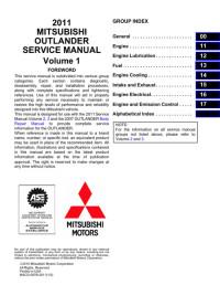
Руководство на английском языке по техническому обслуживание и ремонту автомобиля Mitsubishi Outlander 2011 года выпуска.
- Автор: —
- Издательство: Mitsubishi Motors Corp.
- Год издания: 2010
- Страниц: 7200
- Формат: PDF
- Размер: 191,0 Mb
Сборник мультимедийных руководств на английском языке по техническому обслуживанию и ремонту автомобиля Mitsubishi Outlander 2007-2012 годов выпуска.
- Автор: —
- Издательство: Mitsubishi Motors Corp.
- Год издания: —
- Страниц: —
- Формат: ISO
- Размер: 2,2 Gb
Сборник мультимедийных руководств на английском языке по техническому обслуживанию и ремонту автомобиля Mitsubishi Outlander 2013-2016 годов выпуска.
- Автор: —
- Издательство: Mitsubishi Motors Corp.
- Год издания: —
- Страниц: —
- Формат: ISO
- Размер: 1,9 Gb
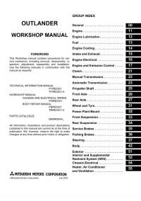
Руководство на английском языке по техническому обслуживанию и ремонту + схемы электрооборудования автомобиля Mitsubishi Outlander первого поколения.
- Автор: —
- Издательство: Mitsubishi Motors Corp.
- Год издания: 2003
- Страниц: —
- Формат: PDF
- Размер: 147,9 Mb
Сборник руководств на английском языке по техническому обслуживание и ремонту автомобиля Mitsubishi Outlander 2007 года выпуска.
- Автор: —
- Издательство: Mitsubishi Motors Corp.
- Год издания: 2006
- Страниц: —
- Формат: PDF
- Размер: 167,3 Mb
Сборник руководство на английском языке по техническому обслуживание и ремонту автомобиля Mitsubishi Outlander 2013 года выпуска.
- Автор: —
- Издательство: Mitsubishi Motors Corp.
- Год издания: 2011
- Страниц: —
- Формат: PDF
- Размер: 133,0 Mb
Сборник руководство на английском и немецком языках по техническому обслуживанию и ремонту автомобиля Mitsubishi Outlander первого поколения.
- Автор: —
- Издательство: Mitsubishi Motors Corp.
- Год издания: 2006
- Страниц: —
- Формат: PDF
- Размер: 428,8 Mb

Руководство по техническому обслуживанию и ремонту автомобиля Mitsubishi Outlander третьего поколения
- Автор: —
- Издательство: Mitsubishi Motors Corp.
- Год издания: —
- Страниц: —
- Формат: PDF
- Размер: 107,4 Mb
Руководство по эксплуатации, техническому обслуживанию и ремонту + каталог расходных запчастей автомобиля Mitsubishi Outlander 2002-2007 годов выпуска с бензиновыми двигателями объемом 2,0/2,4 л.
- Автор: —
- Издательство: Легион-Автодата
- Год издания: —
- Страниц: 526
- Формат: —
- Размер: —
Руководство по эксплуатации, техническому обслуживанию и ремонту + каталог расходных запчастей автомобиля Mitsubishi Outlander III с 2012 года выпуска с бензиновыми двигателями объемом 2,0/2,4/3.0 л.
- Автор: —
- Издательство: Легион-Автодата
- Год издания: —
- Страниц: 590
- Формат: —
- Размер: —
Руководство по эксплуатации, техническому обслуживанию и ремонту + каталог расходных запчастей автомобиля Mitsubishi Outlander 2006-2012 годов выпуска с бензиновыми двигателями объемом 2,0/2,4/3.0 л.
- Автор: —
- Издательство: Легион-Автодата
- Год издания: —
- Страниц: 738
- Формат: —
- Размер: —
Руководство по эксплуатации и ремонту автомобилей Mitsubishi Airtrek и Mitsubishi Outlander XL с 2005 года выпуска с бензиновыми и дизельными двигателями.
- Автор: —
- Издательство: Монолит
- Год издания: —
- Страниц: 458
- Формат: —
- Размер: —
Руководство по эксплуатации и ремонту автомобиля Mitsubishi Outlander с 2009 года выпуска с бензиновыми двигателями объемом 2,0/2,4/3,0 л.
- Автор: —
- Издательство: Монолит
- Год издания: —
- Страниц: 360
- Формат: —
- Размер: —
Руководство по эксплуатации и ремонту автомобиля Mitsubishi Outlander с 2013 года выпуска с бензиновыми и дизельными двигателями.
- Автор: —
- Издательство: Монолит
- Год издания: —
- Страниц: 456
- Формат: —
- Размер: —

Руководство по эксплуатации и техническому обслуживанию автомобиля Mitsubishi Outlander XL с 2006 года выпуска.
- Автор: —
- Издательство: MoToR
- Год издания: —
- Страниц: 510
- Формат: —
- Размер: —
Сборник руководств по эксплуатации и техническому обслуживанию автомобиля Mitsubishi Outlander третьего поколения.
- Автор: —
- Издательство: Mitsubishi Motors Corp.
- Год издания: 2013
- Страниц: —
- Формат: PDF
- Размер: 161,4 Mb

Руководство по эксплуатации и техническому обслуживанию автомобиля Mitsubishi Outlander XL 2007 года выпуска.
- Автор: —
- Издательство: Mitsubishi Motors Corp.
- Год издания: —
- Страниц: 522
- Формат: PDF
- Размер: 27,7 Mb
Руководство по эксплуатации и техническому обслуживанию автомобиля Mitsubishi Outlander XL после рестайлинга.
- Автор: —
- Издательство: Mitsubishi Motors Corp.
- Год издания: 2010
- Страниц: —
- Формат: PDF
- Размер: 85,1 Mb
Руководство по эксплуатации и техническому обслуживанию автомобиля Mitsubishi Outlander первого поколения.
- Автор: —
- Издательство: Mitsubishi Motors
- Год издания: 2005
- Страниц: 350
- Формат: PDF
- Размер: 15,0 Mb
Мультимедийное руководство по эксплуатации, техническому обслуживанию и ремонту автомобиля Mitsubishi Outlander с 2003 года выпуска с двигателями объемом 2,0/2,4 л.
- Автор: —
- Издательство: Новая версия
- Год издания: —
- Страниц: —
- Формат: —
- Размер: 255,4 Mb
