- Manuals
- Brands
- Swan Analytical Instruments Manuals
- Measuring Instruments
- AMI Sodium P
- Operator’s manual
-
Contents
-
Table of Contents
-
Bookmarks
Quick Links
AMI Sodium P
Version 6.00 and higher
A-96.250.211 / 200416
Related Manuals for Swan Analytical Instruments AMI Sodium P
Summary of Contents for Swan Analytical Instruments AMI Sodium P
-
Page 1
AMI Sodium P Version 6.00 and higher A-96.250.211 / 200416… -
Page 2
SWAN representative, or the manufacturer: SWAN ANALYTISCHE INSTRUMENTE AG Studbachstrasse 13 8340 Hinwil Switzerland Internet: www.swan.ch E-mail: support@swan.ch Document Status Monitor AMI Sodium P Operator’s Manual Title: A-96.250.211 Revision Issue April 2005 First edition October 2011 Update to Firmware Release 4.50 April 2014 Main board V2.4, Update to Firmware Release 5.40… -
Page 3: Table Of Contents
Firmware settings for 2nd sample stream option … 3.6. AMI Sodium P connected to a Sample Sequencer … 3.7. Electrical Connections ……. . .
-
Page 4
AMI Sodium P Instrument Setup …….. -
Page 5
AMI Sodium P Error List ……… . . -
Page 6: Safety Instructions
AMI Sodium P Safety Instructions AMI Sodium P — Operator’s Manual This document describes the main steps for instrument setup, oper- ation and maintenance. Safety Instructions General The instructions included in this section explain the potential risks associated with instrument operation and provide important safety practices designed to minimize these risks.
-
Page 7: Warning Notices
AMI Sodium P Safety Instructions 1.1. Warning Notices The symbols used for safety-related notices have the following sig- nificance: DANGER Your life or physical wellbeing are in serious danger if such warnings are ignored. Follow the prevention instructions carefully.
-
Page 8
AMI Sodium P Safety Instructions Warning Signs The importance of the warning signs in this manual. Electrical shock hazard Corrosive Harmful to health Flammable Warning general Attention general A-96.250.211 / 200416… -
Page 9: General Safety Regulations
AMI Sodium P Safety Instructions 1.2. General Safety Regulations Legal The user is responsible for proper system operation. All precautions must be followed to ensure safe operation Requirements of the instrument. Spare Parts Use only official SWAN spare parts and disposables. If other parts are used during the normal warranty period, the manufacturer’s…
-
Page 10: Restrictions For Use
AMI Sodium P Safety Instructions 1.3. Restrictions for use The sample must not contain any particles, which may block the flow cell. Sufficient sample flow is coercive for the correct function of the instrument. This instrument is only applicable to waters of a pH value higher than 7.
-
Page 11: Product Description
The AMI Sodium P is suitable for samples with a pH value higher than pH7. For samples with a pH lower than pH7, use the AMI Sodium A.
-
Page 12
AMI Sodium P Product Description Alarm Relay One potential free contact. Alternatively: Open during normal operation, closed on error and loss of power. Closed during normal operation, open on error and loss of power. Summary alarm indication for programmable alarm values and in- strument faults. -
Page 13
AMI Sodium P Product Description Fluidics Constant head Flow cell Reaction tube Sample outlet Flow regulating valve Overflow tube Sample inlet Air inlet filter Reference electrode Air tube to DIPA bottle pH electrode Tube with DIPA saturated air Sodium electrode… -
Page 14
AMI Sodium P Product Description Second If required the AMI Sodium P can be equipped with the optional second sample stream module. To install the 2nd sample stream Sample Stream option a AMI Sodium P with 400 mm panel with is required. -
Page 15: Instrument Specification
AMI Sodium P Product Description 2.1. Instrument Specification Power Supply Voltage: 100–240 VAC (± 10%) 50/60 Hz (± 5%) or 24 VDC (± 10%) Power consumption: max. 30 VA Electronics Aluminium with a protection degree of IP 66 / NEMA 4X…
-
Page 16
AMI Sodium P Product Description Dimensions: Panel: 280 x 850 x 200 mm Mounting hole distance: 254 x 824 mm Screws: 8 mm diameter Weight: 9.0 kg / 19.85 lbs without sample water 280 mm / 11” 13 mm / ½”… -
Page 17
AMI Sodium P Product Description Dimensions Panel: 400 x 850 x 200 mm with 2nd Mounting hole distance: 374 x 824 mm sample stream Screws: 8 mm diameter Weight: 12.0 kg / 26.5 lbs without sample water 400 mm / 11”… -
Page 18: Instrument Overview
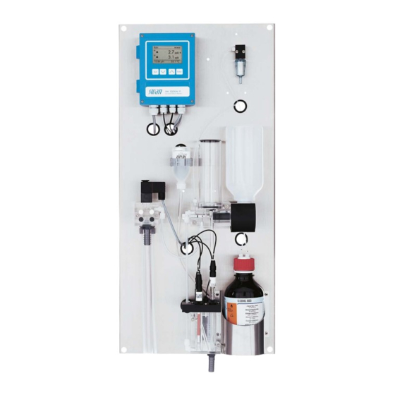
AMI Sodium P Product Description 2.2. Instrument Overview Transmitter Air filter Panel Constant head Reference electrolyte bottle Standard bottle/Grab sample sample stream (option) Standard bottle holder Flow regulating valve Reference electrode Sample inlet Temperature sensor pH electrode Reagent bottle Sodium electrode…
-
Page 19: Installation
AMI Sodium P Installation Installation 3.1. Installation Check List Check Instrument’s specification must conform to the National Electrical Code, all state and local codes, and all plant codes and standards for electrical equipment. On site require- 100 — 240 VAC ( 10%), 50/60 Hz ( 5%) or 24 VDC, isolated ments (±10%) power outlet with ground connection and 30 VA…
-
Page 20: Mounting Of Instrument Panel
AMI Sodium P Installation NOTICE: Do not switch on the Instrument until all electrical Electrical Wiring connections are made. Connect all external devices like limit switches, see Electrical Con- nections, p. Connect power cord. Power-up Turn on the sample flow and wait until the measuring cell is com- pletely filled.
-
Page 21: Connect Sample And Waste
AMI Sodium P Installation 3.3. Connect Sample and Waste 3.3.1 FEP Tube at Sample Inlet CAUTION Damage of acrylic glass flow cell Never screw steel fittings directly into the threads of the acrylic glass. Only use steel tubings with special fitting.
-
Page 22: Install Sensors
AMI Sodium P Installation 3.4. Install Sensors CAUTION The electrodes are made of glass and therefore very sensi- tive. Handle with care. Position of Reference electrode, cable sensors marked with R pH electrode, cable marked with PH Sodium electrode, cable…
-
Page 23: Install The Sodium Electrode
AMI Sodium P Installation 3.4.1 Install the Sodium Electrode General Sodium electrodes are sensitive, electrochemical devices with a very high internal impedance. To maintain correct operation make sure that: the sensing glass bulb stays clean. no air bubbles are trapped in the glass bulb of the electrode.
-
Page 24
AMI Sodium P Installation Install the sodium electrode as follows: 1 Remove the protective cap [I] from the electrode with a careful turning and pulling movement. 2 Etch the electrode, see Cleaning and etching, p. 54 and note the warning about handling of the chemicals. -
Page 25: Install The Reference Electrode
AMI Sodium P Installation 3.4.2 Install the Reference Electrode General The SWAN reference electrode is a double junction Calomel / KCl type electrode. The outer liquid junction is a liquid glass sleeve, guaranteeing easy maintenance and long life time. To maintain correct operation make sure that: …
-
Page 26
AMI Sodium P Installation Prepare the After longer storage of the reference electrode, the diaphragm may be clogged wit salt deposits of KCl. Therefore it is recommended to reference open and clean the diaphragm before installing the reference elec- electrode trode. -
Page 27
AMI Sodium P Installation Install the reference electrode KCl Bottle Connector cap Trapped air bubble Reference chamber hole Dosing tip Electrode shaft Stopper Union screw KCl supply tube Washer Sensor plug O-ring Install the reference electrode as follows: 1 Remove the stopper [D] from the KCl supply tube [E]. -
Page 28
AMI Sodium P Installation 5 Knock against the KCl bottle to remove trapped air bubbles [B] in the dosing tip. NOTICE: Air bubbles trapped in the dosing tip of the KCl bottle may stop the KCl flow to the reference electrode, which results in wrong measuring values. -
Page 29: Install The Ph Electrode
AMI Sodium P Installation 3.4.3 Install the pH Electrode Connector cap Sensor plug Sensor shaft Protective cap Union screw Washer O-ring pH sensor hole 1 Carefully remove the protective cap [D] from the electrode tip. Turn it clockwise only. 2 Rinse the electrode tip with clean water.
-
Page 30: Install The Temperature Sensor
AMI Sodium P Installation 3.4.4 Install the Temperature Sensor The temperature sensor is fixed to the panel with an adhesive tape and already connected to the front end PCB in the AMI transmitter. Temperature sensor Reference sensor pH sensor Sodium sensor…
-
Page 31: Install 2Nd Sample Stream (Option)
AMI Sodium P Installation 3.5. Install 2 Sample Stream (Option) Constant head support Sample stream 1 Blind plug Hose nozzle for drain funnel sample stream option Sample stream 2 with solenoid valve Connection tube Flow regulating valves Existing sample inlet tube…
-
Page 32: Connect The Solenoid Valve
AMI Sodium P Installation 6 Install the connection tube [I] between the 2 sample stream outlet and the constant head support inlet. 7 Connect sample inlet 1 (F) and sample inlet 2 (H) to the corre- sponding inlets at the 2 sample stream.
-
Page 33: Firmware Settings For 2Nd Sample Stream Option
6 Press [Exit], choose <Save> “Yes” Channel switch Auto Confirm with [Enter]. Standards With 2 sample stream option the AMI Sodium P can be operated in the following 4 different modes. None Auto User defined Fieldbus…
-
Page 34: Ami Sodium P Connected To A Sample Sequencer
AMI Sodium P connected to a Sample Sequencer If more than two sample streams are required, an AMI Sample Se- quencer can be connected to the AMI Sodium P which allows to measure up to six sample streams. The electrical connection is de- scribed in the Manual of the AMI Sample Sequencer.
-
Page 35: Electrical Connections
AMI Sodium P Installation 3.7. Electrical Connections WARNING Risk of electrical shock. Do not perform any work on electrical components if the trans- mitter is switched on. Failure to follow safety instructions could result in serious injury or death. Always turn off AC power before manipulating electric parts.
-
Page 36: Alarm Relay
AMI Sodium P Installation WARNING External Voltage. External supplied devices connected to relay 1 or 2 or to the alarm relay can cause electrical shocks Make sure that the devices connected to the following con- tacts are disconnected from the power before resuming in- stallation.
-
Page 37: Connection Diagram
AMI Sodium P Installation 3.7.1 Connection Diagram CAUTION Use only the terminals shown in this diagram, and only for the mentioned purpose. Use of any other terminals will cause short circuits with possible corresponding consequences to material and personnel. A-96.250.211 / 200416…
-
Page 38
Mains cable to comply with standards IEC 60227 or IEC 60245; flammable rating FV1 Mains equipped with an external switch or circuit-breaker – near the instrument – easily accessible to the operator – marked as interrupter for AMI Sodium P A-96.250.211 / 200416… -
Page 39: Relay Contacts
AMI Sodium P Installation 3.8. Relay Contacts 3.8.1 Input NOTICE: Use only potential-free (dry) contacts. The total resistance (sum of cable resistance and resistance of the relay contact) must be less than 50 Ω. Terminals 16/42 For programming see Program list and explanation, 5.3.4, p.
-
Page 40: Relay 1 And 2
AMI Sodium P Installation 3.8.3 Relay 1 and 2 NOTICE: Max. load 1 A/250 VAC Relay 1 and 2 can be configured as normally open or as normally closed. Standard for both relays is normally open. To configure a Relay as normally closed, set the jumper in the upper position.
-
Page 41
AMI Sodium P Installation CAUTION Risk of damage of the relays in the AMI Transmitter due to heavy inductive load. Heavy inductive or directly controlled loads (solenoid valves, dosing pumps) may destroy the relay contacts. To switch inductive loads > 0.1 A use an AMI relay box avail- able as an option or suitable external power relays. -
Page 42: Signal Outputs
AMI Sodium P Installation 3.9. Signal Outputs 3.9.1 Signal Output 1 and 2 (current outputs) NOTICE: Max. burden 510 If signals are sent to two different receivers, use signal isolator (loop isolator). Signal output 1: Terminals 14 (+) and 13 (-)
-
Page 43: Signal Output 3
AMI Sodium P Installation 3.10.1 Signal Output 3 Terminal 38 (+) and 37 (-). Requires the additional board for the third signal output 0/4–20 mA PCB. The third signal output can be operated as current source or current sink (switchable via switch [A]). For detailed information see the corresponding installation instruction.
-
Page 44: Profibus, Modbus Interface
AMI Sodium P Installation 3.10.2 Profibus, Modbus Interface Terminal 37 PB, Terminal 38 PA To connect several instruments by means of a network or to config- ure a PROFIBUS DP or a MODBUS connection, consult the PRO- FIBUS/MODBUS manual. Use appropriate network cable.
-
Page 45: Connection Of Sensors
AMI Sodium P Installation 3.11. Connection of Sensors Front-end board Temperature sensor cable marked with T, Terminal 19 / 20 pH electrode cable marked with pH Reference electrode cable marked with R Sodium electrode cable marked with S A-96.250.211 / 200416…
-
Page 46: Instrument Setup
AMI Sodium P Instrument Setup Instrument Setup 4.1. Install Reagent Bottle CAUTION Formation of reagent vapor To prevent formation of reagent vapors: close the reagent bottle firmly check the EPDM seal regularly install air tubes and filter properly…
-
Page 47: Establish Sample Flow
AMI Sodium P Instrument Setup 4.2. Establish Sample Flow Flow regulating valve Sample inlet Constant head Bottle holder WARNING Risk of water pollution The drain of the Flow cell outlet contains Diisopropylamine (DIPA) At no means recirculate it into the water system.
-
Page 48: Switch On Power
AMI Sodium P Instrument Setup 4.3. Switch on Power First, the instrument performs a self test, displays the firmware ver- sion and then starts normal operation. 1 Let the instrument run continuously for 1 hour with sample. 4.4. Programming Program all parameters for external devices (interface, recorders, etc.) Program all parameters for instrument operation (limits,…
-
Page 49: Operation
AMI Sodium P Operation Operation 5.1. Keys, Display Keys Exit Enter to exit a menu or command (rejecting any changes) to move back to the previous menu level to move DOWN in a menu list and to decrease digits to move UP in a menu list and to increase digits…
-
Page 50
AMI Sodium P Operation Display 15:20:18 21.5 16.8 10.88 pH 22.1°C normal operation HOLD input closed or cal delay: Instrument on hold (shows status of signal outputs). input closed: Control/limit is interrupted (shows status of signal outputs). ERROR Error Fatal Error… -
Page 51: Software Structure
AMI Sodium P Operation 5.2. Software Structure Main Menu Messages Diagnostics Maintenance Operation Installation Menu Messages 1 Messages Reveals pending errors as well as an event history Pending Errors (time and state of events that have occurred at an Message List earlier point of time).
-
Page 52: Changing Parameters And Values
AMI Sodium P Operation 5.3. Changing Parameters and Values Changing The following example shows how to change the logger interval: parameters 1 Select the parameter you want to Sensors Logger 5.1.2 4.4.1 change. Sensor type FOME Log interval 30 min 2 Press [Enter] Disinf.
-
Page 53: Grab Sample
AMI Sodium P Operation 5.4. Grab Sample To perform a grab sample measurement proceed as follows: 1 Rinse a standard bottle well and fill it with grab sample. Do not use closed bottles 2 Screw the grab sample bottle into the standard bottle holder and swing it upwards.
-
Page 54: Maintenance
AMI Sodium P Maintenance Maintenance 6.1. Maintenance Schedule WARNING Stop operation before maintenance. Stop sample flow. Shut off power of the instrument. Check for regular bubble formation. Weekly or Check level of reagent bottle and replace it if necessary.
-
Page 55: Maintenance Of Sodium Electrode
AMI Sodium P Maintenance 6.3. Maintenance of Sodium Electrode Sodium electrodes are sensitive electrochemical devices with very high internal impedance. To maintain correct operation, make sure that the sensing glass bulb stays clean no air bubbles are trapped between glass bulb and glass tube …
-
Page 56
AMI Sodium P Maintenance Mix the etching WARNING solution Health hazard Diluted acidic fluoride solutions are harmful and irritating. Harm- ful if ingested, irritates skin and eyes. Contains less than 0.5% hydrofluoric acid. Contains less than 1% acetic acid. For labora- tory use only. -
Page 57: Maintenance Of Reference Electrode
AMI Sodium P Maintenance 6.4. Maintenance of Reference Electrode Sensor plug Connector cap Union screw Washer O-ring Ring-shaped sleeve Remove the 1 Unscrew and remove the electrode plug [A]. reference Prevent the connector from getting wet. electrode 2 Put on the connector cap [B] onto the electrode.
-
Page 58: Maintenance Of Ph Sensor
AMI Sodium P Maintenance 6.5. Maintenance of pH Sensor Sensor plug Connector cap Union screw Washer O-ring Clean 1 Unscrew and remove the sensor plug [A]. pH sensor Prevent the connector from getting wet. 2 Put the connector cap [B] onto the sensor.
-
Page 59: Maintenance Of Solenoid Valve
AMI Sodium P Maintenance 6.6. Maintenance of Solenoid Valve NOTICE: Only applicable if 2nd sample stream option is installed. Disassemble The solenoid valve is mounted below the constant head. The sole- noid valve should be disassembled if it does not switch anymore or the solenoid if it is clogged.
-
Page 60
AMI Sodium P Maintenance 4 Loosen the fixing screws of the valve body with a 2.5 mm Allen key (D). NOTICE: The O-rings inside the valve body may stick on the flow cell and fall down if the valve body is removed. -
Page 61: Maintenance Of Flow Cell And Constant Head
AMI Sodium P Maintenance 6.7. Maintenance of Flow Cell and Constant Head CAUTION Acrylic glass parts are fragile and scratch-sensitive. Possible damage of acrylic glass parts due to scrubbing materi- als. Never use organic solvents or scrubbing materials to clean acrylic glass parts.
-
Page 62: Cleaning The Flow Cell
AMI Sodium P Maintenance 6.7.1 Cleaning the Flow cell Disassemble 1 Shut off the instrument. the flow cell 2 Close the sample flow main tap. 3 Drain the flow cell [D] completely. 4 Remove all sensors [A]. 5 Remove all tube connections.
-
Page 63: Cleaning The Constant Head
AMI Sodium P Maintenance 6.7.2 Cleaning the Constant Head CAUTION Acrylic glass parts are fragile and scratch-sensitive. Possible damage of acrylic glass parts due to scrubbing materi- als. Never use organic solvents or scrubbing materials to clean acrylic glass parts.
-
Page 64
AMI Sodium P Maintenance Disassemble The flow cell can be disassembled easily. To disassemble the flow cell proceed as follows: the flow cell 1 Shut off the instrument. 2 Stop sample flow. 3 Drain the constant head completely. 4 Remove the constant head cover [A]. -
Page 65: Replace The Air Filter
AMI Sodium P Maintenance 6.8. Replace the Air Filter Insert the air filter (A) in the holder (B) on the right of the transmitter. Exit Enter A Holder B Air filter To replace the air filter proceed as follows: 1 Pull out the polluted air filter of the holder [A].
-
Page 66: Prepare Standard
AMI Sodium P Maintenance 6.9. Prepare Standard Rinse the standard bottles well with deionized water. Prepare the sodium standards directly in the graduated standard bottles using a precision pipette. Make sure the concentrations are programmed correctly. See Menu 5.1.5, p.
-
Page 67: Standard Sodium 1-Point-Calibration
AMI Sodium P Maintenance 4 Press [Enter]. Process pH 3.1.2.4 Current Value 10.78 pH Offset 0.33 mV Process Value 10.78 pH Save <Enter> 5 Enter the correct value with the Process pH 3.1.2.4 ] or [ ] key. Current Value 10.78 pH…
-
Page 68
AMI Sodium P Maintenance Electrode The instrument guides you through the complete calibration pro- cess. If you have completed the required action press <Enter> to Offset proceed. 1 Dismount electrode and rinse in Standard Sodium 3.1.1.5 deionized water. Unmount Electrode… -
Page 69: 2-Point-Calibration
AMI Sodium P Maintenance 6.10.3 2-Point-Calibration Electrode 1 Screw standard bottle 2 onto the Standard Sodium 3.1.1.5 Slope holder and swing bottle upwards. Screw standard 2 bottle onto holder and swing bottle upwards <Enter> to continue 2 Wait until the process has finished.
-
Page 70: Tube Replacement
AMI Sodium P Maintenance 6.11. Tube Replacement 6.11.1 Tube Numbering Tube Length [mm] from Air filter [A] Reagent bottle [C] Reagent bottle [C] Flow cell block [B] A-96.250.211 / 200416…
-
Page 71: Replace The Reaction Tube
AMI Sodium P Maintenance 6.11.2 Replace the Reaction Tube Serto fitting nuts Sealing elements Reaction Tube Light protection sleeves Bubble sensor Flow cell cover 1 Release SERTO fitting nuts [A]. 2 Remove the sealing elements [B] from the reaction tube.
-
Page 72: Replace The Epdm Seal And The Air Inlet Tube
AMI Sodium P Maintenance 6.11.3 Replace the EPDM Seal and the Air Inlet Tube WARNING Diisopropylamine is corrosive. Read the Material Safety Data Sheets (MSDS) first. Wear suitable protective clothing, gloves and eye/face protec- tion. Avoid inhalation of DIPA vapor.
-
Page 73: Replacing Fuses
AMI Sodium P Maintenance 6.12. Replacing Fuses WARNING External Voltage. External supplied devices connected to relay 1 or 2 or to the alarm relay can cause electrical shocks. Make sure that the devices connected to the following con- tacts are disconnected from the power before resuming in- stallation.
-
Page 74: Longer Stop Of Operation
AMI Sodium P Maintenance 6.13. Longer Stop of Operation NOTICE: Store all sensor with tip pointing downwards in a frost- protected room. 1 Shut off the instrument. 2 Stop sample flow. 3 Drain the measuring cell completely. 4 Fill deionized water into the rubber caps of the electrodes.
-
Page 75: Error List
AMI Sodium P Error List Error List Error Non-fatal Error. Indicates an alarm if a programmed value is ex- ceeded. Such Errors are marked E0xx (bold and black). Fatal Error (blinking symbol) Control of dosing devices is interrupted. The indicated measured values are possibly incorrect.
-
Page 76: Ph Alarm High
AMI Sodium P Error List Error Description Corrective action – check process E001 Sodium 1 Alarm high – check programmed value 5.3.1.1/2, p. – check process E002 Sodium 1 Alarm low – check programmed value 5.3.1.1/2, p. – check process (sample pH > 11.5)
-
Page 77
AMI Sodium P Error List Error Description Corrective action – check wiring of temperature sensor E011 Temp. shorted – check temperature sensor – check wiring of temperature sensor E012 Temp. disconnected – check temperature sensor – check case/environment temperature E013 Case Temp. -
Page 78: Program Overview
AMI Sodium P Program Overview Program Overview For explanations about each parameter of the menus see Program List and Explanations, p. 81 Menu 1 Messages is always accessible for everybody. No password protection. No settings can be modified. Menu 2 Diagnostics is always accessible for everybody. No password protection.
-
Page 79: Diagnostics (Main Menu 2)
AMI Sodium P Program Overview 8.2. Diagnostics (Main Menu 2) Identification Designation AMI Sodium P * Menu numbers 2.1* Version V6.00 — 11/15 Factory Test Instrument 2.1.3.1* 2.1.3* Motherboard Front End Operating Time Years / Days / Hours / Minutes / Seconds 2.1.4.1*…
-
Page 80: Maintenance (Main Menu 3)
AMI Sodium P Program Overview 8.3. Maintenance (Main Menu 3) Calibration Standard Sodium (Progress) * Menu numbers 3.1* 3.1.1* Process pH Current Value 3.1.2* Offset Process Value 3.1.2.4* Save <Enter> 3.1.2.5* Simulation Alarm Relay 3.2.1* 3.2* Relay 1 3.2.2* Relay 2 3.2.3*…
-
Page 81: Operation (Main Menu 4)
AMI Sodium P Program Overview 8.4. Operation (Main Menu 4) Sensors Filter Time Const. 4.1.1* 4.1* Hold after Cal. 4.1.2* Channel selection 4.1.3* Relay Contacts Alarm Relay Alarm Sodium 1 and 2 Alarm High 4.2.1.x.1* 4.2* 4.2.1* 4.2.1.1* — 4.2.1.2* Alarm Low 4.2.1.x.x*…
-
Page 82
AMI Sodium P Program Overview Relay Contacts Alarm Relay Alarm Sodium 1 and 2 Alarm High 5.3.1.x.1* 5.3* 5.3.1* 5.3.1.1* — 5.3.1.2* Alarm Low 5.3.1.x.x* Hysteresis 5.3.1.x.x* Delay 5.3.1.x.x* Alarm pH Alarm High 5.3.1.3.1* 5.3.1.3* Alarm Low 5.3.1.3.x* Hysteresis 5.3.1.3.x* Delay 5.3.1.3.x*… -
Page 83: Program List And Explanations
AMI Sodium P Program List and Explanations Program List and Explanations 1 Messages 1.1 Pending Errors 1.1.5 Provides the list of active errors with their status (active, acknowl- edged). If an active error is acknowledged, the alarm relay is active again.
-
Page 84
AMI Sodium P Program List and Explanations 2.2.2.5 Cal. History: Shows the diagnostic values of the last pH electrode calibrations, offset in mV and slope in mV/pH 30 mV Typical offset of pH Electrode 0 mV 59 mV/pH 3 mV/pH Typical slope of pH Electrode 2.2.3… -
Page 85: Maintenance
AMI Sodium P Program List and Explanations 3 Maintenance 3.1 Calibration In this menu, you can correct measuring values, or calibrate offset and slope of pH electrode. 3.1.1 Standard Sodium: Possibility to correct the sodium sensor value. Follow the commands on the screen. Save the value with the <En- ter>…
-
Page 86: Operation
AMI Sodium P Program List and Explanations 4 Operation 4.1 Sensors 4.1.1 Filter Time Constant: Used to damp noisy signals. The higher the filter time constant, the slower the system reacts to changes of the measured value. Range: 5–300 sec 4.1.2…
-
Page 87: Installation
AMI Sodium P Program List and Explanations 5 Installation 5.1 Sensors Sensor type: Display of the used sensor type.(e.g. Sodium) Temperature: Display of the temperature sensor type. (e.g. NT5K) Flow: Display of the actual sample flow B/s 5.1.4 Channel switch: For single sample stream select NONE.
-
Page 88
AMI Sodium P Program List and Explanations 5.2.1.3 Function: Define if the signal output is used to transmit a process value or to drive a control unit. Available functions are: Linear, bilinear or logarithmic for process values. As process values, p. 86 … -
Page 89
AMI Sodium P Program List and Explanations 5.2.1.40 Scaling: Enter beginning and end point (Range low & high) of the linear or logarithmic scale. In addition, the midpoint for the bilinear scale. Parameter Sodium 1 5.2.1.40.10 Range low: 0 ppb–20 ppm 5.2.1.40.20… -
Page 90
AMI Sodium P Program List and Explanations As control out- Signal outputs can be used for driving control units. We distinguish different kinds of controls: P-controller: The controller action is proportional to the devia- tion from the setpoint. The controller is characterized by the P-Band. -
Page 91
AMI Sodium P Program List and Explanations Control upwards/downwards Setpoint: User-defined process value (Measured value or flow) P-Band: Range below (upwards control) or above (downwards control) the set-point, within the dosing intensity is reduced from 100% to 0% to reach the set-point without overshooting. -
Page 92
AMI Sodium P Program List and Explanations 5.3 Relay Contacts 5.3.1 Alarm Relay: The alarm relay is used as cumulative error indicator. Under normal operating conditions the contact is active. The contact is inactive at: Power loss Detection of system faults like defective sensors or electronic parts … -
Page 93
AMI Sodium P Program List and Explanations 5.3.1.3.25 Alarm Low: If the measured value falls below the alarm low value, the alarm relay is activated and E004 is displayed in the message list Range: 0–14.00 pH 5.3.1.3.35 Hysteresis: Within the hyst. range, the relay does not switch. This… -
Page 94
AMI Sodium P Program List and Explanations 5.3.1.5 Sample Temperature: Define the measuring value, which should issue an alarm high respectively low. 5.3.1.5.1 Alarm High: If the sample temperature rises above the pro- grammed value E007 is issued. Range: 30–70 °C 5.3.1.5.x… -
Page 95
AMI Sodium P Program List and Explanations 5.3.2 and 5.3.3 Relay 1 and 2: The contacts can be set as normally open or normally closed with a jumper. See Relay 1 and 2, p. The function of relay contacts 1 or 2 are defined by the user. -
Page 96
AMI Sodium P Program List and Explanations 5.3.2.400 Hysteresis: within the hysteresis range, the relay does not switch. This prevents damage of relay contacts when the measured value fluctuates around the alarm value. Parameter Range Sodium 1 0–20 ppm Sodium 2 0–20 ppm… -
Page 97
AMI Sodium P Program List and Explanations 5.3.2.32.1 Actuator = Time proportional Examples of metering devices that are driven time proportional are solenoid valves, peristaltic pumps. Dosing is controlled by the operating time. 5.3.2.32.20 Cycle time: duration of one control cycle (on/off change). -
Page 98
AMI Sodium P Program List and Explanations 5.3.2.32.4 Control Parameters Range for each Parameter same as 5.2.1.43, p. 89 5.3.2.1 Function = Timer: The relay will be activated repetitively depending on the pro- grammed time scheme. 5.3.2.24 Mode: Operating mode (interval, daily, weekly) 5.3.2.24… -
Page 99
AMI Sodium P Program List and Explanations 5.3.2.24 daily The relay contact can be activated daily, at any time of a day. 5.3.2.341 Start time: to set the start time proceed as follows: 1 Press [Enter], to set the hours. -
Page 100
AMI Sodium P Program List and Explanations 5.3.2.1 Function = Channel Selection: If the 2 sample stream option is installed, relay 2 can be used to indicate which channel is selected. No further parameters are needed. Relay 2 inactive: Channel 1 is selected… -
Page 101
AMI Sodium P Program List and Explanations 5.3.4.4 Fault: No message is issued in pending error list and the alarm relay does not close when input is active. Yes: Message E024 is issued and stored in the mes- sage list. The Alarm relay closes when input is active. -
Page 102
AMI Sodium P Program List and Explanations 5.4.4 Password: Select a password different from 0000 to prevent unau- thorized access to the following menus: 5.4.4.1 Messages 5.4.4.2 Maintenance 5.4.4.3 Operation 5.4.4.4 Installation. Each menu may be protected by a different password. -
Page 103: Material Safety Data Sheet
AMI Sodium P Material Safety Data Sheet Material Safety Data Sheet 10.1. Reagents A-87.729.010A Catalogue No.: Etching Kit A Product name: A-87.729.010B Catalogue No.: Etching Kit B Product name: A-85.141.400 Catalogue No.: Sodium Standard Solution 1’000 ppm Product name: 803646 Catalogue No.:…
-
Page 104: Default Values
AMI Sodium P Default Values Default Values Operation: Sensors: Filter Time Const.:…………..180 Sec Hold after Cal.:…………..300 Sec Alarm Relay …………..same as in Installation Signal Output …………..same as in Installation Relay 1 and 2 …………..same as in Installation Input …………..
-
Page 105
AMI Sodium P Default Values pH: Hysteresis: …………..0.10 pH pH: Delay:…………….5 Sec Flow Alarm:…………….. Yes Sample flow.: Alarm High:……….1000 B/s Sample flow.: Alarm Low: …………5 B/s Sample Temp.: Alarm High: …………. 55 °C Sample Temp.: Alarm Low: …………5 °C Case temp. -
Page 106
AMI Sodium P Default Values Settings: Actuator:……….Time proportional Cycle time: …………….60 s Response time: …………..10 s Settings: Actuator…………Motor valve Run time: …………….60 s Neutral zone: …………….5% If Function = Timer: Mode:………………Interval Interval:…………….. 1 min Mode: ……………… -
Page 107: Index
AMI Sodium P Index Index … . Alarm Logger ..Sample flow Longer Stop of Operation …
-
Page 108
AMI Sodium P Index ..Signal Output ….Signal Outputs Temperature … -
Page 109: Notes
AMI Sodium P Notes Notes A-96.250.211 / 200416…
-
Page 110
AMI Sodium P SWAN is represented worldwide by subsidiary companies and distributors. cooperates with independent representatives all over the world. SWAN Products Analytical Instruments for: High Purity Water Feedwater, Steam and Condensate Potable Water Pool and Sanitary Water Cooling Water…
Swan Analytical Instruments AMI Sodium P Measuring Instruments PDF User Guides and Manuals for Free Download: Found (1) Manuals for Swan Analytical Instruments AMI Sodium P Device Model (Operator’s Manual)
More Measuring Instruments Device Models:
-
Siemens
7KT1 543
Digitale 3-Phasen EnergiezählerDirektanschluß bis 80 A- Wandlerstromanschluß für …/5 Abis 10.000/5 A WARNUNGDie Installation muß von einerElektrofachkraft oder unter derenLeitung und Aufsichtdurchgeführt und geprüft werden.Bei Arbeiten am Meßgerät,Netzspannung abschalten!BedienungsanleitungIIST007-021)ImD …
7KT1 543 Measuring Instruments, 8
-
Eltako electronics
DSZ12DZ-3x65A
Electronic two-way three-phase energy meter DSZ12DZ-3x65A with display, MID approvalMaximum current 3x65A. Standby loss 0.5 watt per path only.Modular device for DIN-EN 60715 TH35 rail mounting. 4 modules = 70mm wide and 58mm deep. Accuracy class B (1%). With S0 interface. The directly measuring two-way three-phase ene …
DSZ12DZ-3x65A Measuring Instruments, 2
-
Max Machinery
213
Max Machinery, Inc. 210 Series User Manual © Copyright 2013 Rev. 002Q4 1 210 Piston Series Positive Displacement Flow MetersModel Model Model Model Model Positive Displacement FlowmetersOperational ManualFor ModelsModel 213, P002, 214, 215 and 216 …
213 Measuring Instruments, 20
-
ABB
Endura AZ30 series
Programming guide COI/AZ30E–EN Rev. DEndura AZ30 series integral probe and remote transmitterCombustion oxygen monitorProven technology for use in hazardous area gases and dustsIntroductionThis Programming Guide provides the following information:– installation details for a remote AZ30 transmitter – see section …
Endura AZ30 series Analytical Instruments, 112
Recommended Documentation:
Table of Contents for Swan Analytical Instruments AMI Sodium P:
-
74 A-96.250.211 / 200416 AMI Sodium P Error List Error Description Corrective action E001 Sodium 1 Alarm high – check process – check programmed value 5.3.1.1/2, p. 90 E002 Sodium 1 Alarm low – check process – check programmed value 5.3.1.1/2, p. 90 E003 pH Alarm high – check process (sample pH > 11.5) – check programmed value, 5.3.1.3.1, p. 90 E004 pH Alarm low – check if reagent bottle is empty – refill reagent E005 Sodium 2 Alarm high – check process – c
-
10 A-96.250.211 / 200416 AMI Sodium P Product Description Alarm Relay One potential free contact. Alternatively: Open during normal operation, closed on error and loss of power. Closed during normal operation, open on error and loss of power. Summary alarm indication for programmable alarm values and in- strument faults. Input For potential-free contact to freeze the measuring value or to inter- rupt control in automated installations (hold function or remote-off).
-
AMI Sodium P Program Overview A-96.250.211 / 200416 77 8.2. Diagnostics (Main Menu 2) Identification Designation AMI Sodium P * Menu numbers 2.1* Version V6.00 — 11/15 Factory Test Instrument 2.1.3.1* 2.1.3* Motherboard Front End Operating Time Years / Days / Hours / Minutes / Seconds 2.1.4.1* 2.1.4* Sensors Sodium Sensor Current Value 2.2* 2.2.1* (Raw value 1) Cal. History Number 2.2.1.5.1* 2.2.1.5* Date, Time Offset Slope pH Electrode Current Value 2.2.2* (Raw value) Cal. History Number 2.2.2.5.1* 2.2.2.5* Da
-
AMI Sodium P Product Description A-96.250.211 / 200416 9 2. Product Description Application Sodium measurement is used for quality control in high purity water applications and to monitor break through of mixed bed ion ex- changers, condenser leaks and the prevention of caustic corrosion of turbines. The AMI Sodium P is suitable for samples with a pH value higher than pH7. For samples with a pH lower than pH7, use the AMI Sodium A. Measurin
-
44 A-96.250.211 / 200416 AMI Sodium P Instrument Setup 4. Instrument Setup 4.1. Install Reagent Bottle CAUTION Formation of reagent vapor To prevent formation of reagent vapors: close the reagent bottle firmly check the EPDM seal regularly install air tubes and filter properly NOTICE: Operate the instrument only with Diisopropylamine. The Tubes are already installed into the tube holder [D] and the EPDM seal [E] seats on the bottom of th
-
AMI Sodium P Installation A-96.250.211 / 200416 27 3.4.3 Install the pH Electrode 1 Carefully remove the protective cap [D] from the electrode tip. Turn it clockwise only. 2 Rinse the electrode tip with clean water. 3 Slip union screw [E], and washer [F] on the electrode shaft [C]. 4 Wet the O-ring [G] and slip it carefully over the electrode shaft. 5 Insert the electrode through the hole [H] in into the flow cell. 6
-
AMI Sodium P Safety Instructions A-96.250.211 / 200416 7 1.2. General Safety Regulations Legal Requirements The user is responsible for proper system operation. All precautions must be followed to ensure safe operation of the instrument. Spare Parts and Disposables Use only official SWAN spare parts and disposables. If other parts are used during the normal warranty period, the manufacturer’s warranty is voided. Modifications Modifications and instrument upgrades shall only be carried out by an authorized Service Technician. SWAN will not
-
96 A-96.250.211 / 200416 AMI Sodium P Program List and Explanations 5.3.2.32.4 Control Parameters Range for each Parameter same as 5.2.1.43, p. 89 The relay will be activated repetitively depending on the pro- grammed time scheme. 5.3.2.24 Mode: Operating mode (interval, daily, weekly) 5.3.2.340 Interval: The interval can be programmed within a range of 1–1’440 min. 5.3.2.44 Run Time: Enter the time the relay stays active. Range: 5–32’400 sec. 5.3.2.54 Delay: during
-
AMI Sodium P Program List and Explanations A-96.250.211 / 200416 99 5.3.4.4 Fault: 5.3.4.5 Delay: Time which the instrument waits, after the input is deactivat- ed, before returning to normal operation. Range: 0–6‘000 sec 5.4 Miscellaneous 5.4.1 Language: Set the desired language. 5.4.2 Set defaults: Reset the instrument to factory default values in three different ways: Calibration: Sets calibration values back to default. All other values are kept
-
A-96.250.211 / 200416 105 AMI Sodium P Index 12. Index A Alarm Sample flow . . . . . . . 91 Alarm pH . . . . . . . . . . . 90 Alarm Relay . . . . . . 37, 102 C Cable thicknesses . . . . . . 33 Cal. History . . . . . . . . . . 81 Calendar . . . . . . . . . . . 97 Changing values . . . . . . . 50 Consumables . . . . . . . . 10 Current outputs . . . . . . . 40 D Default Values . . . . . . . . 102 Diagnostics . . . . . . . . . . 81 E Elect
-
AMI Sodium P Maintenance A-96.250.211 / 200416 53 6.3. Maintenance of Sodium Electrode Sodium electrodes are sensitive electrochemical devices with very high internal impedance. To maintain correct operation, make sure that the sensing glass bulb stays clean no air bubbles are trapped between glass bulb and glass tube the electrical connectors stay absolutely clean and dry. Remove the sodium electrode 1 Unscrew and remove the sensor plug [A]. Prevent the connector from getting wet. 2 Put on the connector cap [B] onto the sensor. 3 Completely
-
36 A-96.250.211 / 200416 AMI Sodium P Installation WARNING Risk of electrical shock Do not perform any work on electrical components if the trans- mitter is switched on. Failure to follow safety instructions could result in serious injury or death. Always turn off AC power before manipulating electric parts. Installation and maintenance of electrical parts must be per- formed by professionals. NOTICE: The protective earth wire (Ground) has to be connected to the grounding terminal. Installation requirements The installation must mee
-
AMI Sodium P Installation A-96.250.211 / 200416 33 3.7. Electrical Connections WARNING Risk of electrical shock. Do not perform any work on electrical components if the trans- mitter is switched on. Failure to follow safety instructions could result in serious injury or death. Always turn off AC power before manipulating electric parts. Grounding requirements: Only operate the inst
-
4 A-96.250.211 / 200416 AMI Sodium P Safety Instructions AMI Sodium P — Operator’s Manual This document describes the main steps for instrument setup, oper- ation and maintenance. 1. Safety Instructions General The instructions included in this section explain the potential risks associated with instrument operation and provide important safety practices designed to minimize these risks. If you carefully follow the information contained in this section
-
108 A-96.250.211 / 200416 AMI Sodium P SWAN is represented worldwide by subsidiary companies and distributors. cooperates with independent representatives all over the world. SWAN Products Analytical Instruments for: High Purity Water Feedwater, Steam and Condensate Potable Water Pool and Sanitary Water Cooling Water Waste Water and Effluents Made in Switzerland
Questions, Opinions and Exploitation Impressions:
You can ask a question, express your opinion or share our experience of Swan Analytical Instruments AMI Sodium P device using right now.
- Manuals
- Brands
- Swann Manuals
- Measuring Instruments
- AMI Sodium P
- Operator’s manual
-
Contents
-
Table of Contents
-
Troubleshooting
-
Bookmarks
Quick Links
A-96.250.211 / 171121
Operator’s Manual
Firmware V6.22 and higher
AMI Sodium P
Related Manuals for Swann AMI Sodium P
Summary of Contents for Swann AMI Sodium P
-
Page 1
A-96.250.211 / 171121 Operator’s Manual Firmware V6.22 and higher AMI Sodium P… -
Page 2
For any technical question, contact your nearest Swan representative, or the manufacturer: Swan Analytische Instrumente AG Studbachstrasse 13 8340 Hinwil Switzerland Internet: www.swan.ch E-mail: support@swan.ch Document Status AMI Sodium P Operator’s Manual Title: A-96.250.211 Revision Issue April 2005 First edition October 2011 Update to Firmware Release 4.50 April 2014 Mainboard V2.4, Update to Firmware Release 5.40… -
Page 3: Table Of Contents
3.5. Installing the 2nd Sample Stream Option ……33 3.6. AMI Sodium P Connected to AMI Sample Sequencer ….35 3.7.
-
Page 4
AMI Sodium P Instrument Setup ……….50 4.1. -
Page 5
AMI Sodium P Program Overview……….89 8.1. -
Page 6: Safety Instructions
AMI Sodium P Safety Instructions Operator’s Manual This document describes the main steps for instrument setup, opera- tion and maintenance. Safety Instructions General The instructions included in this section explain the potential risks associated with instrument operation and provide important safety practices designed to minimize these risks.
-
Page 7: Warning Notices
AMI Sodium P Safety Instructions 1.1. Warning Notices The symbols used for safety-related notices have the following meaning: DANGER Your life or physical wellbeing are in serious danger if such warn- ings are ignored. Follow the prevention instructions carefully.
-
Page 8
AMI Sodium P Safety Instructions Warning Signs The warning signs in this manual have the following meaning: Electrical shock hazard Corrosive Harmful to health Flammable Warning general Attention general A-96.250.211 / 171121… -
Page 9: General Safety Regulations
AMI Sodium P Safety Instructions 1.2. General Safety Regulations Legal The user is responsible for proper system operation. All precautions must be followed to ensure safe operation of the instrument. Requirements Spare Parts Use only official SWAN spare parts and disposables. If other parts are used during the normal warranty period, the manufacturer’s war-…
-
Page 10: Restrictions For Use
AMI Sodium P Safety Instructions 1.3. Restrictions for use The sample must not contain any particles, which may block the flow cell. Sufficient sample flow is coercive for the correct function of the instrument. This instrument is only suitable for water with a pH value of more than 7.
-
Page 11: Product Description
The AMI Sodium P is suitable for samples with a pH value higher than pH7. For samples with a pH lower than pH7, use the AMI Sodium A.
-
Page 12
AMI Sodium P Product Description Alarm Relay One potential free contact. Alternatively: Open during normal operation, closed on error and loss of power. Closed during normal operation, open on error and loss of power. Summary alarm indication for programmable alarm values and in- strument faults. -
Page 13
AMI Sodium P Product Description Fluidics Constant head Sample outlet Reaction tube Overflow tube Flow regulating valve Air inlet filter Sample inlet Air tube to DIPA bottle Reference electrode Automatic regeneration module (option) pH electrode Sodium electrode Magnetic valve Temperature sensor… -
Page 14
To install the 2 sample stream option, Sample Stream an AMI Sodium P with 400 mm or 375 mm panel width is required. Sample If measurement of more than two sample streams is required, the AMI Sodium P can be connected to a Sample Sequencer, which al- Sequencer lows to measure up to six sample streams. -
Page 15: Instrument Specification
AMI Sodium P Product Description 2.1. Instrument Specification Power Supply AC variant: 100–240 VAC (± 10%) 50/60 Hz (± 5%) DC variant 10–36 VDC Power consumption: max. 35 VA Transmitter Housing: aluminum, with a protection degree of specifications IP 66 / NEMA 4X Ambient temperature: −10 to +50 °C…
-
Page 16
AMI Sodium P Product Description Dimensions Panel: stainless steel Dimensions: 280 x 850 x 200 mm Screws: 8 mm diameter Weight: 9.0 kg / 19.85 lbs without sample water 280 mm / 11.02″ 254 mm / 10.00″ Exit Enter AMI Sodium P… -
Page 17
AMI Sodium P Product Description Dimensions Panel: stainless steel with 2nd Dimensions: 400 x 850 x 200 mm sample stream Screws: 8 mm diameter Weight: 12.0 kg / 26.5 lbs without sample water 400 mm / 15.75″ 374 mm / 14.72″… -
Page 18
AMI Sodium P Product Description Dimensions of Panel: stainless steel compact panel Dimensions: 375 x 700 x 200 mm version Screws: 8 mm diameter Weight: 9.0 kg / 19.85 lbs without sample water 375 mm / 14.76″ 17.5 mm / 0.69″… -
Page 19: Instrument Overview
AMI Sodium P Product Description 2.2. Instrument Overview Transmitter Air filter Panel Constant head Reference electrolyte bottle Standard bottle/Grab sample sample stream (option) Standard bottle holder Flow regulating valve Reference electrode Sample inlet Temperature sensor pH electrode Reagent bottle Sodium electrode…
-
Page 20: Installation
AMI Sodium P Installation Installation 3.1. Installation Checklist On-site AC variant: 100–240 VAC ( 10%), 50/60 Hz ( 5%) requirements DC variant: 10–36 VDC Power consumption: 35 VA maximum. Protective earth connection required. Sample line with sufficient sample flow and pressure (see Instru- ment Specification, p.
-
Page 21
AMI Sodium P Installation Reagent and Install the air filter. filter connections Install the reagent bottle. We recommend to use DIPA to operate the instrument. Use a reagent bottle with either G45 thread (Schott) or a bottle from Merck using a thread adapter. Close the bottle well to prevent the forma- tion of reagent vapors. -
Page 22: Mounting Of Instrument Panel
AMI Sodium P Installation 3.2. Mounting of Instrument Panel The first part of this chapter describes the preparing and placing of the instrument for use. The instrument must only be installed by trained personnel. Mount the instrument in vertical position.
-
Page 23: Connecting Sample And Waste
AMI Sodium P Installation 3.3. Connecting Sample and Waste 3.3.1 FEP Tube at Sample Inlet CAUTION Damage of acrylic glass flow cell Never screw steel fittings directly into the threads of the acrylic glass. Only use steel tubings with special fitting.
-
Page 24: Installing Sensors
AMI Sodium P Installation 3.4. Installing Sensors CAUTION The electrodes are made of glass and therefore very sensitive Handle with care. Position of Reference electrode, cable sensors marked with R pH electrode, cable marked with PH Sodium electrode, cable…
-
Page 25: Installing The Sodium Electrode
AMI Sodium P Installation 3.4.1 Installing the Sodium Electrode General Sodium electrodes are sensitive, electrochemical devices with a very high internal impedance. To maintain correct operation make sure that: the sensing glass bulb stays clean. no air bubbles are trapped in the glass bulb of the electrode.
-
Page 26
AMI Sodium P Installation Install the sodium electrode as follows: 1 Remove the protective cap [I] from the electrode with a careful turning and pulling movement. 2 Etch the electrode, see Cleaning and etching, p. 63 and note the warning about handling of the chemicals. -
Page 27: Installing The Reference Electrode
AMI Sodium P Installation 3.4.2 Installing the Reference Electrode General The SWAN reference electrode is a double junction Calomel / KCl type electrode. The outer liquid junction is a liquid glass sleeve, guar- anteeing easy maintenance and long life time.
-
Page 28
AMI Sodium P Installation Prepare the After longer storage of the reference electrode, the diaphragm may be clogged with salt deposits of KCl. Therefore it is recommended to reference open and clean the diaphragm before installing the reference elec- electrode trode. -
Page 29
AMI Sodium P Installation Install the reference electrode KCl bottle KCl supply tube Trapped air bubble Reference chamber hole Dosing tip Electrode shaft Stopper Union screw Sensor plug Washer Connector cap O-ring Install the reference electrode as follows: 1 Remove the stopper [D] from the KCl supply tube [G]. -
Page 30
AMI Sodium P Installation 3 Fix the KCl bottle upside down in the holder on the panel. 4 Puncture the bottle bottom to allow pressure equilibration. 5 Knock against the KCl bottle to remove trapped air bubbles [B] in the dosing tip. -
Page 31: Installing The Ph Electrode
AMI Sodium P Installation 3.4.3 Installing the pH Electrode Connector cap Sensor plug Sensor shaft Protective cap Union screw Washer O-ring pH sensor hole 1 Carefully remove the protective cap [D] from the electrode tip. Turn it clockwise only. 2 Rinse the electrode tip with clean water.
-
Page 32: Installing The Temperature Sensor
AMI Sodium P Installation 3.4.4 Installing the Temperature Sensor The temperature sensor is fixed to the panel with an adhesive tape and already connected to the front end PCB in the AMI transmitter. Temperature sensor Reference sensor pH sensor Sodium sensor…
-
Page 33: Installing The 2Nd Sample Stream Option
AMI Sodium P Installation 3.5. Installing the 2 Sample Stream Option Constant head support Sample stream 1 Blind plug Hose nozzle for drain funnel sample stream option Sample stream 2 with solenoid valve Connection tube Flow regulating valves Existing sample inlet tube…
-
Page 34
AMI Sodium P Installation 6 Install the connection tube [I] between the 2 sample stream outlet and the constant head support inlet. 7 Connect sample inlet 1 [F] and sample inlet 2 [H] to the corre- sponding inlets at the 2 sample stream. -
Page 35: Ami Sodium P Connected To Ami Sample Sequencer
Sequencer If more than two sample streams are required, an AMI Sample Se- quencer can be connected to the AMI Sodium P, which allows to measure up to six sample streams. The electrical connection is de- scribed in the manual of the AMI Sample Sequencer.
-
Page 36: Installing The Automatic Regeneration Option
AMI Sodium P Installation 3.7. Installing the Automatic Regeneration Option Mechanical 1 Stop the sample flow at the main tap. installation 2 Switch off the instrument. 3 Remove the elbow piece from the inlet of the flow cell and screw in the enclosed T-piece [A].
-
Page 37
AMI Sodium P Installation Exit Enter AMI Sodium P A-96.250.211 / 171121… -
Page 38
AMI Sodium P Installation Electrical connection WARNING Electrical shock hazard! Before opening the AMI transmitter switch power off. Use one of the PG7 cable glands to feed the cable of the solenoid valve into the AMI transmitter housing. 1 Remove the plug [A] from the cable gland [B]. -
Page 39: Electrical Connections
AMI Sodium P Installation 3.8. Electrical Connections WARNING Risk of electrical shock Do not perform any work on electrical components if the transmit- ter is switched on. Failure to follow safety instructions could result in serious injury or death. Always turn off power before manipulating electric parts.
-
Page 40
AMI Sodium P Installation WARNING External Voltage. External supplied devices connected to relay 1 or 2 or to the alarm relay can cause electrical shocks Make sure that the devices connected to the following contacts are disconnected from the power before resuming installation. -
Page 41: Connection Diagram
AMI Sodium P Installation 3.8.1 Connection Diagram CAUTION Use only the terminals shown in this diagram, and only for the mentioned purpose. Use of any other terminals will cause short circuits with possible corresponding consequences to material and personnel. A-96.250.211 / 171121…
-
Page 42
Mains cable to comply with standards IEC 60227 or IEC 60245; flammable rating FV1 Mains equipped with an external switch or circuit-breaker – near the instrument – easily accessible to the operator – marked as interrupter for AMI Sodium P A-96.250.211 / 171121… -
Page 43: Relay Contacts
AMI Sodium P Installation 3.9. Relay Contacts 3.9.1 Input Note: Use only potential-free (dry) contacts. The total resistance (sum of cable resistance and resistance of the relay contact) must be less than 50 Ω. Terminals 16/42 For programming see Program list and explanation, 5.3.4, p.
-
Page 44: Relay 1 And 2
AMI Sodium P Installation 3.9.3 Relay 1 and 2 Note: Max. load 1 A/250 VAC Relay 1 and 2 can be configured as normally open or as normally closed. Standard for both relays is normally open. To configure a Re- lay as normally closed, set the jumper in the upper position.
-
Page 45
AMI Sodium P Installation CAUTION Risk of damage of the relays in the AMI Transmitter due to heavy inductive load. Heavy inductive or directly controlled loads (solenoid valves, dos- ing pumps) may destroy the relay contacts. To switch inductive loads > 0.1 A use an AMI relay box avail- able as an option or suitable external power relays. -
Page 46: Signal Outputs
AMI Sodium P Installation 3.10. Signal Outputs 3.10.1 Signal Output 1 and 2 (current outputs) Note: Max. burden 510 Ω If signals are sent to two different receivers, use signal isolator (loop isolator). Signal output 1: Terminals 14 (+) and 13 (-)
-
Page 47: Signal Output 3
AMI Sodium P Installation 3.11.1 Signal Output 3 Terminals 38 (+) and 37 (-). Requires the additional board for the third signal output 0/4–20 mA. The third signal output can be operated as a current source or as a current sink (switchable via switch [A]). For detailed information see the corresponding installation instruction.
-
Page 48: Hart Interface
AMI Sodium P Installation 3.11.3 HART Interface Terminals 38 (+) and 37 (-). The HART interface PCB allows for communication via the HART protocol. For detailed information, consult the HART manual. HART Interface PCB 3.11.4 USB Interface The USB Interface is used to store Logger data and for Firmware up- load.
-
Page 49: Connection Of Sensors
AMI Sodium P Installation 3.12. Connection of Sensors Front-end board Temperature sensor cable marked with T, Terminal 19 / 20 pH electrode cable marked with pH Reference electrode cable marked with R Sodium electrode cable marked with S A-96.250.211 / 171121…
-
Page 50: Instrument Setup
AMI Sodium P Instrument Setup Instrument Setup 4.1. Installing the Reagent Bottle CAUTION Formation of reagent vapor To prevent formation of reagent vapors: close the reagent bottle firmly check the EPDM seal regularly install air tubes and filter properly…
-
Page 51: Installing The Regeneration Solution Bottle
AMI Sodium P Instrument Setup The tubes are already installed into the tube holder [D] and the EPDM seal [E] seats on the bottom of the tube holder. To install the DIPA bottle proceed as follows: 1 Put the DIPA bottle [G] into the bottle holder [H].
-
Page 52: Establish Sample Flow
AMI Sodium P Instrument Setup 4.3. Establish Sample Flow Flow regulating valve Sample inlet Constant head Holder for grab sample bottle WARNING Risk of water pollution The drain of the Flow cell outlet contains Diisopropylamine (DIPA) At no means recirculate it into the water system.
-
Page 53: Switch On Power
AMI Sodium P Instrument Setup 4.4. Switch on Power Let the instrument run continuously for 1 hour with sample. 4.5. Programming External Program all parameters for external devices (interface, recorders, etc.). See 5.2 Signal Outputs, p. 99 5.3 Relay Contacts, p.
-
Page 54: Operation
AMI Sodium P Operation Operation 5.1. Keys, Display Exit Enter to exit a menu or command (rejecting any changes) to move back to the previous menu level to move DOWN in a menu list and to decrease digits to move UP in a menu list and to increase digits…
-
Page 55
AMI Sodium P Operation Display 15:20:18 21.5 16.8 10.88 pH 22.1°C normal operation HOLD input closed or cal delay: Instrument on hold (shows status of signal outputs). input closed: Control/limit is interrupted (shows status of signal outputs). ERROR Error Fatal Error… -
Page 56: Software Structure
AMI Sodium P Operation 5.2. Software Structure Main Menu Messages Diagnostics Maintenance Operation Installation Menu Messages 1 Messages Reveals pending errors as well as an event history Pending Errors (time and state of events that have occurred at an Message List earlier point of time).
-
Page 57: Changing Parameters And Values
AMI Sodium P Operation 5.3. Changing Parameters and Values Changing The following example shows how to change the logger interval: parameters 1 Select the parameter you want to Sensors Logger 5.1.2 4.4.1 change. Sensor type FOME Log interval 30 min 2 Press [Enter] Disinf.
-
Page 58: Grab Sample
AMI Sodium P Operation 5.4. Grab Sample CAUTION Incorrect measurement If the automatic regeneration option is installed, make sure that no automatic regeneration is running when starting the grab sam- ple measurement. This would falsify the measured value. To perform a grab sample measurement proceed as follows: 1 Rinse a standard bottle well and fill it with grab sample.
-
Page 59
AMI Sodium P Operation 4 After the grab sample bottle is empty, swing the bottle holder down and unscrew the grab sample bottle. 5 Press the [ ] key again. HOLD appears in the display (= cal delay). After the delay time is over, the instrument goes back to the normal operating mode. -
Page 60: Maintenance
AMI Sodium P Maintenance Maintenance 6.1. Maintenance Schedule Check for regular bubble formation. Weekly or every 2 weeks Check fill level of DIPA bottle Etch the sodium electrode using SWAN’s etching kit. Perform a one-point calibration.
-
Page 61: Stop Of Operation For Maintenance
AMI Sodium P Maintenance 6.2. Stop of Operation for Maintenance 1 Stop sample flow. 2 Shut off power of the instrument. 3 Disconnect the reagent bottle and close it. 4 If the automatic regeneration module is installed, swing down, unscrew and close the regeneration solution bottle.
-
Page 62: Maintenance Of Sodium Electrode
AMI Sodium P Maintenance 6.3. Maintenance of Sodium Electrode Sodium electrodes are sensitive electrochemical devices with very high internal impedance. To maintain correct operation, make sure that the sensing glass bulb stays clean no air bubbles are trapped between glass bulb and glass tube …
-
Page 63
AMI Sodium P Maintenance Mix the etching WARNING solution Health hazard Diluted acidic fluoride solutions are harmful and irritating. Harmful if ingested, irritates skin and eyes. Contains less than 0.5% hy- drofluoric acid. Contains less than 1% acetic acid. For laboratory use only. -
Page 64: Maintenance Of Reference Electrode
AMI Sodium P Maintenance 6.4. Maintenance of Reference Electrode Sensor plug Connector cap Union screw Washer O-ring Ring-shaped sleeve Remove the 1 Unscrew and remove the electrode plug [A]. reference Prevent the connector from getting wet. electrode 2 Put on the connector cap [B] onto the electrode.
-
Page 65: Maintenance Of Ph Sensor
AMI Sodium P Maintenance 6.5. Maintenance of pH Sensor Sensor plug Connector cap Union screw Washer O-ring Clean 1 Unscrew and remove the sensor plug [A]. pH sensor Prevent the connector from getting wet. 2 Put the connector cap [B] onto the sensor.
-
Page 66: Maintenance Of Solenoid Valve
AMI Sodium P Maintenance 6.6. Maintenance of Solenoid Valve 6.6.1 Sample Stream Option Disassemble 1 Switch off the instrument according to instructions in Stop of Op- eration for Maintenance, p. the solenoid valve 2 Loosen the nut [A]. 3 Remove the solenoid coil [B] from the valve body [C].
-
Page 67
AMI Sodium P Maintenance Note: The O-rings inside the valve body may stick on the flow cell and fall down if the valve body is removed. 5 Remove the valve body from the flow cell. 6 Remove the white plate [G] with a screw driver size 0 [F]. -
Page 68: Automatic Regeneration Option
AMI Sodium P Maintenance 6.6.2 Automatic Regeneration Option Note: Never use the membranes again after a valve has been opened. Preparation 1 Swing down and remove the regeneration solution bottle. 2 Screw on a bottle filled with water and swing it upwards.
-
Page 69
AMI Sodium P Maintenance Drawing Knurled nut Coil body Solenoid support Washer 2 Long spring Solenoid with membrane holder Membrane 2 Valve body Teflon distance bar Membrane 1 Membrane holder Conical spring Washer 1 Bottom nut Assembling 1 Put new membranes on the membrane holders. -
Page 70: Maintenance Of Flow Cell And Constant Head
AMI Sodium P Maintenance 6.7. Maintenance of Flow Cell and Constant Head CAUTION Acrylic glass parts are fragile and scratch-sensitive Possible damage of acrylic glass parts due to scrubbing materials. Never use organic solvents or scrubbing materials to clean acrylic glass parts.
-
Page 71: Cleaning The Flow Cell
AMI Sodium P Maintenance 6.7.1 Cleaning the Flow cell Disassemble 1 Shut off the instrument. the flow cell 2 Close the sample flow main tap. 3 Drain the flow cell [D] completely. 4 Remove all sensors [A]. 5 Remove all tube connections.
-
Page 72: Cleaning The Constant Head
AMI Sodium P Maintenance 6.7.2 Cleaning the Constant Head CAUTION Acrylic glass parts are fragile and scratch-sensitive. Possible damage of acrylic glass parts due to scrubbing materi- als. Never use organic solvents or scrubbing materials to clean acrylic glass parts.
-
Page 73
AMI Sodium P Maintenance Disassemble The flow cell can be easily disassembled. Proceed as follows: the flow cell 1 Shut off the instrument. 2 Stop sample flow. 3 Drain the constant head completely. 4 Remove the constant head cover [A]. -
Page 74: Replacing The Air Filter
AMI Sodium P Maintenance 6.8. Replacing the Air Filter Insert the air filter [B] in the holder [A] on the right of the transmitter. Exit Enter A Holder B Air filter To replace the air filter proceed as follows: 1 Pull out the polluted air filter of the holder [A].
-
Page 75: Preparing The Standard
AMI Sodium P Maintenance 6.9. Preparing the Standard Rinse the standard bottles well with deionized water. Prepare the sodium standards directly in the graduated standard bottles using a precision pipette. Make sure the concentrations are programmed correctly. See menu 5.1.5, p.
-
Page 76: Calibration
AMI Sodium P Maintenance 6.10. Calibration CAUTION Incorrect measurement If the automatic regeneration option is installed, make sure that no automatic regeneration is running when starting the pH pro- cess or sodium standard calibration. This would falsify the result of the calibration.
-
Page 77: Standard Sodium 1-Point Calibration
AMI Sodium P Maintenance 6 Press [Enter] to save. Process pH 3.1.2.4 Current Value 10.78 pH Offset 0.33 mV Process Value 10.70 pH Save <Enter> Process pH 3.1.2.5 Current Value 10.70 pH Offset -3.80 mV Calibration successful 7 Remove pH electrode from the measuring cell.
-
Page 78
AMI Sodium P Maintenance 3 Mount electrode and wait 2-3 Standard Sodium 3.1.1.5 minutes. Mount electrode and wait 2 — 3 minutes <Enter> to continue 4 Screw standard bottle 1 onto the Standard Sodium 3.1.1.5 holder and swing bottle upwards. -
Page 79: 2-Point Calibration
AMI Sodium P Maintenance 6.10.3 2-Point Calibration Electrode 1 Screw standard bottle 2 onto the Standard Sodium 3.1.1.5 Slope holder and swing bottle upwards. Screw standard 2 bottle onto holder and swing bottle upwards <Enter> to continue 2 Wait until the process has finished.
-
Page 80: Tube Replacement
AMI Sodium P Maintenance 6.11. Tube Replacement 6.11.1 Tube Numbering Tube No from Air filter [A] Reagent [G] Reagent [G] Flow cell block [C] Solenoid valve NC [F] T-piece [H] Solenoid valve Co [E] Regeneration solution bottle [B] *The “NO” port of the 3-way valve must be sealed with a blind plug.
-
Page 81: Replacing The Reaction Tube
AMI Sodium P Maintenance 6.11.2 Replacing the Reaction Tube Serto fitting nuts Sealing elements Reaction tube Light protection sleeves Bubble sensor Flow cell cover 1 Release SERTO fitting nuts [A]. 2 Remove the sealing elements [B] from the reaction tube.
-
Page 82: Replacing The Epdm Seal And The Air Inlet Tube
AMI Sodium P Maintenance 6.11.3 Replacing the EPDM Seal and the Air Inlet Tube WARNING Diisopropylamine is corrosive. Read the Material Safety Data Sheets (MSDS) first. Wear suitable protective clothing, gloves and eye/face protec- tion. Avoid inhalation of DIPA vapor.
-
Page 83: Longer Stop Of Operation
AMI Sodium P Maintenance 6.12. Longer Stop of Operation Note: Store all sensors with tip pointing downwards in a frost- protected room. 1 Stop sample flow. 2 Drain the measuring cell completely. 3 Fill deionized water into the rubber caps of the electrodes.
-
Page 84: Troubleshooting
AMI Sodium P Troubleshooting Troubleshooting 7.1. Error List Error Non-fatal Error. Indicates an alarm if a programmed value is exceeded. Such Errors are marked E0xx (bold and black). Fatal Error (blinking symbol) Control of dosing devices is interrupted. The indicated measured values are possibly incorrect.
-
Page 85
AMI Sodium P Troubleshooting Error Description Corrective action – check process E001 Sodium 1 Alarm high – check programmed value 5.3.1.1/2, p. – check process E002 Sodium 1 Alarm low – check programmed value 5.3.1.1/2, p. – check process (sample pH > 11.5) -
Page 86
AMI Sodium P Troubleshooting Error Description Corrective action – check wiring of temperature sensor E011 Temp. shorted – check temperature sensor – check wiring of temperature sensor E012 Temp. disconnected – check temperature sensor – check case/environment temperature E013 Case Temp. high –… -
Page 87: Automatic Regeneration
AMI Sodium P Troubleshooting 7.2. Automatic Regeneration Note: Only applicable if the automatic regeneration module is installed. Problem Possible Reasons No automatic The automatic regeneration does not start if regeneration is one of the following errors is present: performed E010 Sample flow low …
-
Page 88: Replacing Fuses
AMI Sodium P Troubleshooting 7.3. Replacing Fuses WARNING External Voltage. External supplied devices connected to relay 1 or 2 or to the alarm relay can cause electrical shocks. Make sure that the devices connected to the following contacts are disconnected from the power before resuming installation.
-
Page 89: Program Overview
AMI Sodium P Program Overview Program Overview For explanations about each parameter of the menus see Program List and Explanations, p. 94 Menu 1 Messages informs about pending errors and mainte- nance tasks and shows the error history. Password protection possible.
-
Page 90: Diagnostics (Main Menu 2)
AMI Sodium P Program Overview 8.2. Diagnostics (Main Menu 2) Identification * Menu numbers Designation AMI Sodium P 2.1* Version V6.22 — 06/21 Factory Test 2.1.3.1* Instrument 2.1.3* Motherboard Front End Operating Time Years / Days / Hours / Minutes / Seconds 2.1.4.1*…
-
Page 91: Maintenance (Main Menu 3)
AMI Sodium P Program Overview 8.3. Maintenance (Main Menu 3) Calibration Standard Sodium * Menu numbers (Progress) 3.1* 3.1.1* Process pH Current Value 3.1.2* Offset 3.1.2.4* Process Value Save <Enter> 3.1.2.5* Regeneration Manual Operation Valve Open 3.2* 3.2.1* 3.2.1.1* Closed Parameters 3.2.2.1*…
-
Page 92: Operation (Main Menu 4)
AMI Sodium P Program Overview 8.4. Operation (Main Menu 4) Sensors 4.1.1* * Menu numbers Filter Time Const. 4.1* 4.1.2* Hold after Cal. 4.1.3* Channel selection Relay Contacts Alarm Relay Alarm Sodium 1 and 2 Alarm High 4.2.1.x.1* 4.2* 4.2.1* 4.2.1.1* — 4.2.1.2*…
-
Page 93
AMI Sodium P Program Overview Relay Contacts Alarm Relay Alarm Sodium 1 and 2 Alarm High 5.3.1.x.1* 5.3* 5.3.1* 5.3.1.1* — 5.3.1.2* Alarm Low 5.3.1.x.x* 5.3.1.x.x* Hysteresis 5.3.1.x.x* Delay Alarm pH 5.3.1.3.1* Alarm High 5.3.1.3* 5.3.1.3.x* Alarm Low Hysteresis 5.3.1.3.x* 5.3.1.3.x*… -
Page 94: Program List And Explanations
AMI Sodium P Program List and Explanations Program List and Explanations 1 Messages 1.1 Pending Errors 1.1.5 Provides the list of active errors with their status (active, acknowl- edged). If an active error is acknowledged, the alarm relay is active again.
-
Page 95: Maintenance
AMI Sodium P Program List and Explanations 2.2.2.5 Cal. History: Shows the diagnostic values of the last pH electrode calibrations, offset in mV and slope in mV/pH. Typical offset of pH Electrode 0 mV 30 mV Typical slope of pH Electrode 59 mV/pH …
-
Page 96
AMI Sodium P Program List and Explanations 3.2 Regeneration Note: The Regeneration menu is only visible if the automatic regeneration option is installed. 3.2.1 Manual operation: Allows to manually open and close the solenoid valve to test it or to fill the tube with regeneration solution. -
Page 97: Operation
AMI Sodium P Program List and Explanations 3.3 Simulation To simulate a value or a relay state, select the alarm relay, relay 1 or 2 signal output 1 or 2 valve 1 with the [ ] or [ ] key.
-
Page 98
AMI Sodium P Program List and Explanations 4.1.31 Interval: Only visible if <Channel switch> in menu 5.1.4 is set to <Auto>. The measuring interval can be set in steps of 15 min. Range: 15 min to 120 min 4.1.32 Channel selection: Only visible if <Channel switch> in menu 5.1.4 is set to <User defined>. -
Page 99: Installation
AMI Sodium P Program List and Explanations 5 Installation 5.1 Sensors Sensor type: Display of the used sensor type.(e.g. Sodium) Temperature: Display of the temperature sensor type. (e.g. NT5K) Flow: Display of the actual sample flow B/s 5.1.4 Channel switch: For single sample stream select “None”.
-
Page 100
AMI Sodium P Program List and Explanations As process The process value can be represented in 3 ways: linear, bilinear or logarithmic. See graphs below. values [mA] 0 / 4 X Measured value linear bilinear [mA] 0 / 4 1’000 10’000… -
Page 101
AMI Sodium P Program List and Explanations Parameter pH 5.2.1.40.12 Range low: 0 –14 pH 5.2.1.40.22 Range high: 0 –14 pH Parameter Temperature 5.2.1.40.13 Range low: — 30 to +120 °C 5.2.1.40.23 Range high: -30 to +120 °C Parameter Sample flow 5.2.1.40.14… -
Page 102
AMI Sodium P Program List and Explanations Ziegler-Nichols method for the optimization of a PID controller: Parameters: Setpoint, P-Band, Reset time, Derivative time. Response to maximum control output = 1.2/a Tangent on the inflection point = 2L Time = L/2 The point of intersection of the tangent with the respective axis will result in the parameters a and L. -
Page 103
AMI Sodium P Program List and Explanations 5.2.1.43 Control Parameters: if Parameters = Temperature 5.2.1.43.13 Setpoint: -30 to +120 °C 5.2.1.43.23 P-Band: 0 –100 °C 5.2.1.43 Control Parameters: if Parameters = Sample Flow 5.2.1.43.14 Setpoint: 0–1000 B /s 5.2.1.43.24 P-Band: 0 –1000 B/s 5.2.1.43.3… -
Page 104
AMI Sodium P Program List and Explanations 5.3.1.1/2 Alarm Sodium 1 and 2 5.3.1.x.x Alarm High: If the measured value rises above the alarm high value, the alarm relay is activated and E001 is displayed in the message list. Range: 0.00–20.00 ppm 5.3.1.x.x… -
Page 105
AMI Sodium P Program List and Explanations 5.3.1.4.1 Flow Alarm: Program if the alarm relay should be activated if there is a flow alarm. Choose between yes or no. The flow alarm will always be indicated in the display, pending error list, saved in the message list and the logger. -
Page 106
AMI Sodium P Program List and Explanations 5.3.2 and 5.3.3 Relay 1 and 2: The contacts can be set as normally open or normally closed with a jumper. See Relay 1 and 2, p. The function of relay contacts 1 or 2 are defined by the user. -
Page 107
AMI Sodium P Program List and Explanations 5.3.2.50 Delay: Duration, the activation of the alarm relay is retarded after the measuring value has risen above/fallen below the programmed alarm. Range. 0–600 sec 5.3.2.1 Function = Control upwards/downwards: The relays may be used to drive control units such as solenoid valves, membrane dosing pumps or motor valves. -
Page 108
AMI Sodium P Program List and Explanations 5.3.2.32.31 Control Parameters Range for each Parameter same as 5.2.1.43, p. 102 5.3.2.32.1 Actuator = Motor valve Dosing is controlled by the position of a motor driven mixing valve. 5.3.2.32.22 Run time: Time needed to open a completely closed valve Range: 5–300 sec. -
Page 109
AMI Sodium P Program List and Explanations 5.3.2.7 Output/Control: Select operating mode of the controller output: Controller continues normally. Cont.: Controller continues based on the last valid value. Hold: Controller is switched off. Off: 5.3.2.24 daily The relay contact can be activated daily, at any time of a day. -
Page 110
AMI Sodium P Program List and Explanations 5.3.2.1 Function = Fieldbus: The relay will be switched via the Profibus input. No further parame- ters are needed. 5.3.2.1 Function = Channel Selection: If the 2 sample stream option is installed, relay 2 can be used to in- dicate which channel is selected. -
Page 111
AMI Sodium P Program List and Explanations 5.3.4.3 Output/Control: (relay or signal output): Controller continues normally. Cont.: Controller continues on the last valid value. Hold: Controller is switched off. Off: 5.3.4.4 Fault: No message is issued in pending error list and the alarm relay does not close when input is active. -
Page 112
AMI Sodium P Program List and Explanations 5.4.3 Load Firmware: Firmware updates should be done by instructed ser- vice personnel only. Load Firmware 5.4.4 Password: Select a password different from 0000 to prevent unau- thorized access to the following menus: 5.4.4.1… -
Page 113: Material Safety Data Sheet
AMI Sodium P Material Safety Data Sheet Material Safety Data Sheet 10.1. Reagents A-87.729.010A Catalogue No.: Etching Kit A Product name: A-87.729.010B Catalogue No.: Etching Kit B Product name: A-85.141.400 Catalogue No.: Sodium Standard Solution 1’000 ppm Product name: 803646 Catalogue No.:…
-
Page 114: Default Values
AMI Sodium P Default Values Default Values Note: The <Maintenance>/<Regeneration> menu is only visible if the automatic regeneration option is installed. Maintenance: Regeneration Start time …………….01:00:00 Calendar: Monday to Sunday: …………Off Duration: ………………20 s Delay: ………………300 s Signal Outputs: …………….hold Output/Control: …………….hold…
-
Page 115
AMI Sodium P Default Values Scaling: pH: Range high: …………14.00 pH Scaling: Sample Flow: Range low: ……….0 B/s Scaling: Sample Flow: Range high:……..1000 B/s Alarm Relay Alarm Sodium: Alarm high:…………….. 20.00 ppm Alarm low: …………….0.00 ppb Hysteresis: …………….10.0 ppb Delay:………………… -
Page 116
AMI Sodium P Default Values Parameter:…………..Sample Flow Settings: Actuator: …………Frequency Settings: Pulse Frequency:………….120/min Settings: Control Parameters: Setpoint:……1000 B /s Settings: Control Parameters: P-band: …….100 B/s Common settings Settings: Control Parameters: Reset time:……..0 s Settings: Control Parameters: Derivative Time: ……0 s Settings: Control Parameters: Control Timeout:……0 min… -
Page 117: Index
AMI Sodium P Index Index ….Profibus ….Alarm ..
-
Page 118
AMI Sodium P Index … Sensors ….Signal Outputs USB Interface . -
Page 119: Notes
AMI Sodium P Notes Notes A-96.250.211 / 171121…
-
Page 120
Swan Products — Analytical Instruments for: Swan is represented worldwide by subsidiary companies and distributors and cooperates with independent representatives all over the world. For contact in- formation, please scan the QR code. Swan Analytical Instruments ∙ CH-8340 Hinwil www.swan.ch ∙ swan@swan.ch AMI Sodium P…
-
Page 1
AMI Sodium P Version 6.00 and higher A-96.250.211 / 200416… -
Page 2
SWAN representative, or the manufacturer: SWAN ANALYTISCHE INSTRUMENTE AG Studbachstrasse 13 8340 Hinwil Switzerland Internet: www.swan.ch E-mail: support@swan.ch Document Status Monitor AMI Sodium P Operator’s Manual Title: A-96.250.211 Revision Issue April 2005 First edition October 2011 Update to Firmware Release 4.50 April 2014 Main board V2.4, Update to Firmware Release 5.40… -
Page 3: Table Of Contents
Firmware settings for 2nd sample stream option … 3.6. AMI Sodium P connected to a Sample Sequencer … 3.7. Electrical Connections ……. . .
-
Page 4
AMI Sodium P Instrument Setup …….. -
Page 5
AMI Sodium P Error List ……… . . -
Page 6: Safety Instructions
AMI Sodium P Safety Instructions AMI Sodium P — Operator’s Manual This document describes the main steps for instrument setup, oper- ation and maintenance. Safety Instructions General The instructions included in this section explain the potential risks associated with instrument operation and provide important safety practices designed to minimize these risks.
-
Page 7: Warning Notices
AMI Sodium P Safety Instructions 1.1. Warning Notices The symbols used for safety-related notices have the following sig- nificance: DANGER Your life or physical wellbeing are in serious danger if such warnings are ignored. Follow the prevention instructions carefully.
-
Page 8
AMI Sodium P Safety Instructions Warning Signs The importance of the warning signs in this manual. Electrical shock hazard Corrosive Harmful to health Flammable Warning general Attention general A-96.250.211 / 200416… -
Page 9: General Safety Regulations
AMI Sodium P Safety Instructions 1.2. General Safety Regulations Legal The user is responsible for proper system operation. All precautions must be followed to ensure safe operation Requirements of the instrument. Spare Parts Use only official SWAN spare parts and disposables. If other parts are used during the normal warranty period, the manufacturer’s…
-
Page 10: Restrictions For Use
AMI Sodium P Safety Instructions 1.3. Restrictions for use The sample must not contain any particles, which may block the flow cell. Sufficient sample flow is coercive for the correct function of the instrument. This instrument is only applicable to waters of a pH value higher than 7.
-
Page 11: Product Description
The AMI Sodium P is suitable for samples with a pH value higher than pH7. For samples with a pH lower than pH7, use the AMI Sodium A.
-
Page 12
AMI Sodium P Product Description Alarm Relay One potential free contact. Alternatively: Open during normal operation, closed on error and loss of power. Closed during normal operation, open on error and loss of power. Summary alarm indication for programmable alarm values and in- strument faults. -
Page 13
AMI Sodium P Product Description Fluidics Constant head Flow cell Reaction tube Sample outlet Flow regulating valve Overflow tube Sample inlet Air inlet filter Reference electrode Air tube to DIPA bottle pH electrode Tube with DIPA saturated air Sodium electrode… -
Page 14
AMI Sodium P Product Description Second If required the AMI Sodium P can be equipped with the optional second sample stream module. To install the 2nd sample stream Sample Stream option a AMI Sodium P with 400 mm panel with is required. -
Page 15: Instrument Specification
AMI Sodium P Product Description 2.1. Instrument Specification Power Supply Voltage: 100–240 VAC (± 10%) 50/60 Hz (± 5%) or 24 VDC (± 10%) Power consumption: max. 30 VA Electronics Aluminium with a protection degree of IP 66 / NEMA 4X…
-
Page 16
AMI Sodium P Product Description Dimensions: Panel: 280 x 850 x 200 mm Mounting hole distance: 254 x 824 mm Screws: 8 mm diameter Weight: 9.0 kg / 19.85 lbs without sample water 280 mm / 11” 13 mm / ½”… -
Page 17
AMI Sodium P Product Description Dimensions Panel: 400 x 850 x 200 mm with 2nd Mounting hole distance: 374 x 824 mm sample stream Screws: 8 mm diameter Weight: 12.0 kg / 26.5 lbs without sample water 400 mm / 11”… -
Page 18: Instrument Overview
AMI Sodium P Product Description 2.2. Instrument Overview Transmitter Air filter Panel Constant head Reference electrolyte bottle Standard bottle/Grab sample sample stream (option) Standard bottle holder Flow regulating valve Reference electrode Sample inlet Temperature sensor pH electrode Reagent bottle Sodium electrode…
-
Page 19: Installation
AMI Sodium P Installation Installation 3.1. Installation Check List Check Instrument’s specification must conform to the National Electrical Code, all state and local codes, and all plant codes and standards for electrical equipment. On site require- 100 — 240 VAC ( 10%), 50/60 Hz ( 5%) or 24 VDC, isolated ments (±10%) power outlet with ground connection and 30 VA…
-
Page 20: Mounting Of Instrument Panel
AMI Sodium P Installation NOTICE: Do not switch on the Instrument until all electrical Electrical Wiring connections are made. Connect all external devices like limit switches, see Electrical Con- nections, p. Connect power cord. Power-up Turn on the sample flow and wait until the measuring cell is com- pletely filled.
-
Page 21: Connect Sample And Waste
AMI Sodium P Installation 3.3. Connect Sample and Waste 3.3.1 FEP Tube at Sample Inlet CAUTION Damage of acrylic glass flow cell Never screw steel fittings directly into the threads of the acrylic glass. Only use steel tubings with special fitting.
-
Page 22: Install Sensors
AMI Sodium P Installation 3.4. Install Sensors CAUTION The electrodes are made of glass and therefore very sensi- tive. Handle with care. Position of Reference electrode, cable sensors marked with R pH electrode, cable marked with PH Sodium electrode, cable…
-
Page 23: Install The Sodium Electrode
AMI Sodium P Installation 3.4.1 Install the Sodium Electrode General Sodium electrodes are sensitive, electrochemical devices with a very high internal impedance. To maintain correct operation make sure that: the sensing glass bulb stays clean. no air bubbles are trapped in the glass bulb of the electrode.
-
Page 24
AMI Sodium P Installation Install the sodium electrode as follows: 1 Remove the protective cap [I] from the electrode with a careful turning and pulling movement. 2 Etch the electrode, see Cleaning and etching, p. 54 and note the warning about handling of the chemicals. -
Page 25: Install The Reference Electrode
AMI Sodium P Installation 3.4.2 Install the Reference Electrode General The SWAN reference electrode is a double junction Calomel / KCl type electrode. The outer liquid junction is a liquid glass sleeve, guaranteeing easy maintenance and long life time. To maintain correct operation make sure that: …
-
Page 26
AMI Sodium P Installation Prepare the After longer storage of the reference electrode, the diaphragm may be clogged wit salt deposits of KCl. Therefore it is recommended to reference open and clean the diaphragm before installing the reference elec- electrode trode. -
Page 27
AMI Sodium P Installation Install the reference electrode KCl Bottle Connector cap Trapped air bubble Reference chamber hole Dosing tip Electrode shaft Stopper Union screw KCl supply tube Washer Sensor plug O-ring Install the reference electrode as follows: 1 Remove the stopper [D] from the KCl supply tube [E]. -
Page 28
AMI Sodium P Installation 5 Knock against the KCl bottle to remove trapped air bubbles [B] in the dosing tip. NOTICE: Air bubbles trapped in the dosing tip of the KCl bottle may stop the KCl flow to the reference electrode, which results in wrong measuring values. -
Page 29: Install The Ph Electrode
AMI Sodium P Installation 3.4.3 Install the pH Electrode Connector cap Sensor plug Sensor shaft Protective cap Union screw Washer O-ring pH sensor hole 1 Carefully remove the protective cap [D] from the electrode tip. Turn it clockwise only. 2 Rinse the electrode tip with clean water.
-
Page 30: Install The Temperature Sensor
AMI Sodium P Installation 3.4.4 Install the Temperature Sensor The temperature sensor is fixed to the panel with an adhesive tape and already connected to the front end PCB in the AMI transmitter. Temperature sensor Reference sensor pH sensor Sodium sensor…
-
Page 31: Install 2Nd Sample Stream (Option)
AMI Sodium P Installation 3.5. Install 2 Sample Stream (Option) Constant head support Sample stream 1 Blind plug Hose nozzle for drain funnel sample stream option Sample stream 2 with solenoid valve Connection tube Flow regulating valves Existing sample inlet tube…
-
Page 32: Connect The Solenoid Valve
AMI Sodium P Installation 6 Install the connection tube [I] between the 2 sample stream outlet and the constant head support inlet. 7 Connect sample inlet 1 (F) and sample inlet 2 (H) to the corre- sponding inlets at the 2 sample stream.
-
Page 33: Firmware Settings For 2Nd Sample Stream Option
6 Press [Exit], choose <Save> “Yes” Channel switch Auto Confirm with [Enter]. Standards With 2 sample stream option the AMI Sodium P can be operated in the following 4 different modes. None Auto User defined Fieldbus…
-
Page 34: Ami Sodium P Connected To A Sample Sequencer
AMI Sodium P connected to a Sample Sequencer If more than two sample streams are required, an AMI Sample Se- quencer can be connected to the AMI Sodium P which allows to measure up to six sample streams. The electrical connection is de- scribed in the Manual of the AMI Sample Sequencer.
-
Page 35: Electrical Connections
AMI Sodium P Installation 3.7. Electrical Connections WARNING Risk of electrical shock. Do not perform any work on electrical components if the trans- mitter is switched on. Failure to follow safety instructions could result in serious injury or death. Always turn off AC power before manipulating electric parts.
-
Page 36: Alarm Relay
AMI Sodium P Installation WARNING External Voltage. External supplied devices connected to relay 1 or 2 or to the alarm relay can cause electrical shocks Make sure that the devices connected to the following con- tacts are disconnected from the power before resuming in- stallation.
-
Page 37: Connection Diagram
AMI Sodium P Installation 3.7.1 Connection Diagram CAUTION Use only the terminals shown in this diagram, and only for the mentioned purpose. Use of any other terminals will cause short circuits with possible corresponding consequences to material and personnel. A-96.250.211 / 200416…
-
Page 38
Mains cable to comply with standards IEC 60227 or IEC 60245; flammable rating FV1 Mains equipped with an external switch or circuit-breaker – near the instrument – easily accessible to the operator – marked as interrupter for AMI Sodium P A-96.250.211 / 200416… -
Page 39: Relay Contacts
AMI Sodium P Installation 3.8. Relay Contacts 3.8.1 Input NOTICE: Use only potential-free (dry) contacts. The total resistance (sum of cable resistance and resistance of the relay contact) must be less than 50 Ω. Terminals 16/42 For programming see Program list and explanation, 5.3.4, p.
-
Page 40: Relay 1 And 2
AMI Sodium P Installation 3.8.3 Relay 1 and 2 NOTICE: Max. load 1 A/250 VAC Relay 1 and 2 can be configured as normally open or as normally closed. Standard for both relays is normally open. To configure a Relay as normally closed, set the jumper in the upper position.
-
Page 41
AMI Sodium P Installation CAUTION Risk of damage of the relays in the AMI Transmitter due to heavy inductive load. Heavy inductive or directly controlled loads (solenoid valves, dosing pumps) may destroy the relay contacts. To switch inductive loads > 0.1 A use an AMI relay box avail- able as an option or suitable external power relays. -
Page 42: Signal Outputs
AMI Sodium P Installation 3.9. Signal Outputs 3.9.1 Signal Output 1 and 2 (current outputs) NOTICE: Max. burden 510 If signals are sent to two different receivers, use signal isolator (loop isolator). Signal output 1: Terminals 14 (+) and 13 (-)
-
Page 43: Signal Output 3
AMI Sodium P Installation 3.10.1 Signal Output 3 Terminal 38 (+) and 37 (-). Requires the additional board for the third signal output 0/4–20 mA PCB. The third signal output can be operated as current source or current sink (switchable via switch [A]). For detailed information see the corresponding installation instruction.
-
Page 44: Profibus, Modbus Interface
AMI Sodium P Installation 3.10.2 Profibus, Modbus Interface Terminal 37 PB, Terminal 38 PA To connect several instruments by means of a network or to config- ure a PROFIBUS DP or a MODBUS connection, consult the PRO- FIBUS/MODBUS manual. Use appropriate network cable.
-
Page 45: Connection Of Sensors
AMI Sodium P Installation 3.11. Connection of Sensors Front-end board Temperature sensor cable marked with T, Terminal 19 / 20 pH electrode cable marked with pH Reference electrode cable marked with R Sodium electrode cable marked with S A-96.250.211 / 200416…
-
Page 46: Instrument Setup
AMI Sodium P Instrument Setup Instrument Setup 4.1. Install Reagent Bottle CAUTION Formation of reagent vapor To prevent formation of reagent vapors: close the reagent bottle firmly check the EPDM seal regularly install air tubes and filter properly…
-
Page 47: Establish Sample Flow
AMI Sodium P Instrument Setup 4.2. Establish Sample Flow Flow regulating valve Sample inlet Constant head Bottle holder WARNING Risk of water pollution The drain of the Flow cell outlet contains Diisopropylamine (DIPA) At no means recirculate it into the water system.
-
Page 48: Switch On Power
AMI Sodium P Instrument Setup 4.3. Switch on Power First, the instrument performs a self test, displays the firmware ver- sion and then starts normal operation. 1 Let the instrument run continuously for 1 hour with sample. 4.4. Programming Program all parameters for external devices (interface, recorders, etc.) Program all parameters for instrument operation (limits,…
-
Page 49: Operation
AMI Sodium P Operation Operation 5.1. Keys, Display Keys Exit Enter to exit a menu or command (rejecting any changes) to move back to the previous menu level to move DOWN in a menu list and to decrease digits to move UP in a menu list and to increase digits…
-
Page 50
AMI Sodium P Operation Display 15:20:18 21.5 16.8 10.88 pH 22.1°C normal operation HOLD input closed or cal delay: Instrument on hold (shows status of signal outputs). input closed: Control/limit is interrupted (shows status of signal outputs). ERROR Error Fatal Error… -
Page 51: Software Structure
AMI Sodium P Operation 5.2. Software Structure Main Menu Messages Diagnostics Maintenance Operation Installation Menu Messages 1 Messages Reveals pending errors as well as an event history Pending Errors (time and state of events that have occurred at an Message List earlier point of time).
-
Page 52: Changing Parameters And Values
AMI Sodium P Operation 5.3. Changing Parameters and Values Changing The following example shows how to change the logger interval: parameters 1 Select the parameter you want to Sensors Logger 5.1.2 4.4.1 change. Sensor type FOME Log interval 30 min 2 Press [Enter] Disinf.
-
Page 53: Grab Sample
AMI Sodium P Operation 5.4. Grab Sample To perform a grab sample measurement proceed as follows: 1 Rinse a standard bottle well and fill it with grab sample. Do not use closed bottles 2 Screw the grab sample bottle into the standard bottle holder and swing it upwards.
-
Page 54: Maintenance
AMI Sodium P Maintenance Maintenance 6.1. Maintenance Schedule WARNING Stop operation before maintenance. Stop sample flow. Shut off power of the instrument. Check for regular bubble formation. Weekly or Check level of reagent bottle and replace it if necessary.
-
Page 55: Maintenance Of Sodium Electrode
AMI Sodium P Maintenance 6.3. Maintenance of Sodium Electrode Sodium electrodes are sensitive electrochemical devices with very high internal impedance. To maintain correct operation, make sure that the sensing glass bulb stays clean no air bubbles are trapped between glass bulb and glass tube …
-
Page 56
AMI Sodium P Maintenance Mix the etching WARNING solution Health hazard Diluted acidic fluoride solutions are harmful and irritating. Harm- ful if ingested, irritates skin and eyes. Contains less than 0.5% hydrofluoric acid. Contains less than 1% acetic acid. For labora- tory use only. -
Page 57: Maintenance Of Reference Electrode
AMI Sodium P Maintenance 6.4. Maintenance of Reference Electrode Sensor plug Connector cap Union screw Washer O-ring Ring-shaped sleeve Remove the 1 Unscrew and remove the electrode plug [A]. reference Prevent the connector from getting wet. electrode 2 Put on the connector cap [B] onto the electrode.
-
Page 58: Maintenance Of Ph Sensor
AMI Sodium P Maintenance 6.5. Maintenance of pH Sensor Sensor plug Connector cap Union screw Washer O-ring Clean 1 Unscrew and remove the sensor plug [A]. pH sensor Prevent the connector from getting wet. 2 Put the connector cap [B] onto the sensor.
-
Page 59: Maintenance Of Solenoid Valve
AMI Sodium P Maintenance 6.6. Maintenance of Solenoid Valve NOTICE: Only applicable if 2nd sample stream option is installed. Disassemble The solenoid valve is mounted below the constant head. The sole- noid valve should be disassembled if it does not switch anymore or the solenoid if it is clogged.
-
Page 60
AMI Sodium P Maintenance 4 Loosen the fixing screws of the valve body with a 2.5 mm Allen key (D). NOTICE: The O-rings inside the valve body may stick on the flow cell and fall down if the valve body is removed. -
Page 61: Maintenance Of Flow Cell And Constant Head
AMI Sodium P Maintenance 6.7. Maintenance of Flow Cell and Constant Head CAUTION Acrylic glass parts are fragile and scratch-sensitive. Possible damage of acrylic glass parts due to scrubbing materi- als. Never use organic solvents or scrubbing materials to clean acrylic glass parts.
-
Page 62: Cleaning The Flow Cell
AMI Sodium P Maintenance 6.7.1 Cleaning the Flow cell Disassemble 1 Shut off the instrument. the flow cell 2 Close the sample flow main tap. 3 Drain the flow cell [D] completely. 4 Remove all sensors [A]. 5 Remove all tube connections.
-
Page 63: Cleaning The Constant Head
AMI Sodium P Maintenance 6.7.2 Cleaning the Constant Head CAUTION Acrylic glass parts are fragile and scratch-sensitive. Possible damage of acrylic glass parts due to scrubbing materi- als. Never use organic solvents or scrubbing materials to clean acrylic glass parts.
-
Page 64
AMI Sodium P Maintenance Disassemble The flow cell can be disassembled easily. To disassemble the flow cell proceed as follows: the flow cell 1 Shut off the instrument. 2 Stop sample flow. 3 Drain the constant head completely. 4 Remove the constant head cover [A]. -
Page 65: Replace The Air Filter
AMI Sodium P Maintenance 6.8. Replace the Air Filter Insert the air filter (A) in the holder (B) on the right of the transmitter. Exit Enter A Holder B Air filter To replace the air filter proceed as follows: 1 Pull out the polluted air filter of the holder [A].
-
Page 66: Prepare Standard
AMI Sodium P Maintenance 6.9. Prepare Standard Rinse the standard bottles well with deionized water. Prepare the sodium standards directly in the graduated standard bottles using a precision pipette. Make sure the concentrations are programmed correctly. See Menu 5.1.5, p.
-
Page 67: Standard Sodium 1-Point-Calibration
AMI Sodium P Maintenance 4 Press [Enter]. Process pH 3.1.2.4 Current Value 10.78 pH Offset 0.33 mV Process Value 10.78 pH Save <Enter> 5 Enter the correct value with the Process pH 3.1.2.4 ] or [ ] key. Current Value 10.78 pH…
-
Page 68
AMI Sodium P Maintenance Electrode The instrument guides you through the complete calibration pro- cess. If you have completed the required action press <Enter> to Offset proceed. 1 Dismount electrode and rinse in Standard Sodium 3.1.1.5 deionized water. Unmount Electrode… -
Page 69: 2-Point-Calibration
AMI Sodium P Maintenance 6.10.3 2-Point-Calibration Electrode 1 Screw standard bottle 2 onto the Standard Sodium 3.1.1.5 Slope holder and swing bottle upwards. Screw standard 2 bottle onto holder and swing bottle upwards <Enter> to continue 2 Wait until the process has finished.
-
Page 70: Tube Replacement
AMI Sodium P Maintenance 6.11. Tube Replacement 6.11.1 Tube Numbering Tube Length [mm] from Air filter [A] Reagent bottle [C] Reagent bottle [C] Flow cell block [B] A-96.250.211 / 200416…
-
Page 71: Replace The Reaction Tube
AMI Sodium P Maintenance 6.11.2 Replace the Reaction Tube Serto fitting nuts Sealing elements Reaction Tube Light protection sleeves Bubble sensor Flow cell cover 1 Release SERTO fitting nuts [A]. 2 Remove the sealing elements [B] from the reaction tube.
-
Page 72: Replace The Epdm Seal And The Air Inlet Tube
AMI Sodium P Maintenance 6.11.3 Replace the EPDM Seal and the Air Inlet Tube WARNING Diisopropylamine is corrosive. Read the Material Safety Data Sheets (MSDS) first. Wear suitable protective clothing, gloves and eye/face protec- tion. Avoid inhalation of DIPA vapor.
-
Page 73: Replacing Fuses
AMI Sodium P Maintenance 6.12. Replacing Fuses WARNING External Voltage. External supplied devices connected to relay 1 or 2 or to the alarm relay can cause electrical shocks. Make sure that the devices connected to the following con- tacts are disconnected from the power before resuming in- stallation.
-
Page 74: Longer Stop Of Operation
AMI Sodium P Maintenance 6.13. Longer Stop of Operation NOTICE: Store all sensor with tip pointing downwards in a frost- protected room. 1 Shut off the instrument. 2 Stop sample flow. 3 Drain the measuring cell completely. 4 Fill deionized water into the rubber caps of the electrodes.
-
Page 75: Error List
AMI Sodium P Error List Error List Error Non-fatal Error. Indicates an alarm if a programmed value is ex- ceeded. Such Errors are marked E0xx (bold and black). Fatal Error (blinking symbol) Control of dosing devices is interrupted. The indicated measured values are possibly incorrect.
-
Page 76: Ph Alarm High
AMI Sodium P Error List Error Description Corrective action – check process E001 Sodium 1 Alarm high – check programmed value 5.3.1.1/2, p. – check process E002 Sodium 1 Alarm low – check programmed value 5.3.1.1/2, p. – check process (sample pH > 11.5)
-
Page 77
AMI Sodium P Error List Error Description Corrective action – check wiring of temperature sensor E011 Temp. shorted – check temperature sensor – check wiring of temperature sensor E012 Temp. disconnected – check temperature sensor – check case/environment temperature E013 Case Temp. -
Page 78: Program Overview
AMI Sodium P Program Overview Program Overview For explanations about each parameter of the menus see Program List and Explanations, p. 81 Menu 1 Messages is always accessible for everybody. No password protection. No settings can be modified. Menu 2 Diagnostics is always accessible for everybody. No password protection.
-
Page 79: Diagnostics (Main Menu 2)
AMI Sodium P Program Overview 8.2. Diagnostics (Main Menu 2) Identification Designation AMI Sodium P * Menu numbers 2.1* Version V6.00 — 11/15 Factory Test Instrument 2.1.3.1* 2.1.3* Motherboard Front End Operating Time Years / Days / Hours / Minutes / Seconds 2.1.4.1*…
-
Page 80: Maintenance (Main Menu 3)
AMI Sodium P Program Overview 8.3. Maintenance (Main Menu 3) Calibration Standard Sodium (Progress) * Menu numbers 3.1* 3.1.1* Process pH Current Value 3.1.2* Offset Process Value 3.1.2.4* Save <Enter> 3.1.2.5* Simulation Alarm Relay 3.2.1* 3.2* Relay 1 3.2.2* Relay 2 3.2.3*…
-
Page 81: Operation (Main Menu 4)
AMI Sodium P Program Overview 8.4. Operation (Main Menu 4) Sensors Filter Time Const. 4.1.1* 4.1* Hold after Cal. 4.1.2* Channel selection 4.1.3* Relay Contacts Alarm Relay Alarm Sodium 1 and 2 Alarm High 4.2.1.x.1* 4.2* 4.2.1* 4.2.1.1* — 4.2.1.2* Alarm Low 4.2.1.x.x*…
-
Page 82
AMI Sodium P Program Overview Relay Contacts Alarm Relay Alarm Sodium 1 and 2 Alarm High 5.3.1.x.1* 5.3* 5.3.1* 5.3.1.1* — 5.3.1.2* Alarm Low 5.3.1.x.x* Hysteresis 5.3.1.x.x* Delay 5.3.1.x.x* Alarm pH Alarm High 5.3.1.3.1* 5.3.1.3* Alarm Low 5.3.1.3.x* Hysteresis 5.3.1.3.x* Delay 5.3.1.3.x*… -
Page 83: Program List And Explanations
AMI Sodium P Program List and Explanations Program List and Explanations 1 Messages 1.1 Pending Errors 1.1.5 Provides the list of active errors with their status (active, acknowl- edged). If an active error is acknowledged, the alarm relay is active again.
-
Page 84
AMI Sodium P Program List and Explanations 2.2.2.5 Cal. History: Shows the diagnostic values of the last pH electrode calibrations, offset in mV and slope in mV/pH 30 mV Typical offset of pH Electrode 0 mV 59 mV/pH 3 mV/pH Typical slope of pH Electrode 2.2.3… -
Page 85: Maintenance
AMI Sodium P Program List and Explanations 3 Maintenance 3.1 Calibration In this menu, you can correct measuring values, or calibrate offset and slope of pH electrode. 3.1.1 Standard Sodium: Possibility to correct the sodium sensor value. Follow the commands on the screen. Save the value with the <En- ter>…
-
Page 86: Operation
AMI Sodium P Program List and Explanations 4 Operation 4.1 Sensors 4.1.1 Filter Time Constant: Used to damp noisy signals. The higher the filter time constant, the slower the system reacts to changes of the measured value. Range: 5–300 sec 4.1.2…
-
Page 87: Installation
AMI Sodium P Program List and Explanations 5 Installation 5.1 Sensors Sensor type: Display of the used sensor type.(e.g. Sodium) Temperature: Display of the temperature sensor type. (e.g. NT5K) Flow: Display of the actual sample flow B/s 5.1.4 Channel switch: For single sample stream select NONE.
-
Page 88
AMI Sodium P Program List and Explanations 5.2.1.3 Function: Define if the signal output is used to transmit a process value or to drive a control unit. Available functions are: Linear, bilinear or logarithmic for process values. As process values, p. 86 … -
Page 89
AMI Sodium P Program List and Explanations 5.2.1.40 Scaling: Enter beginning and end point (Range low & high) of the linear or logarithmic scale. In addition, the midpoint for the bilinear scale. Parameter Sodium 1 5.2.1.40.10 Range low: 0 ppb–20 ppm 5.2.1.40.20… -
Page 90
AMI Sodium P Program List and Explanations As control out- Signal outputs can be used for driving control units. We distinguish different kinds of controls: P-controller: The controller action is proportional to the devia- tion from the setpoint. The controller is characterized by the P-Band. -
Page 91
AMI Sodium P Program List and Explanations Control upwards/downwards Setpoint: User-defined process value (Measured value or flow) P-Band: Range below (upwards control) or above (downwards control) the set-point, within the dosing intensity is reduced from 100% to 0% to reach the set-point without overshooting. -
Page 92
AMI Sodium P Program List and Explanations 5.3 Relay Contacts 5.3.1 Alarm Relay: The alarm relay is used as cumulative error indicator. Under normal operating conditions the contact is active. The contact is inactive at: Power loss Detection of system faults like defective sensors or electronic parts … -
Page 93
AMI Sodium P Program List and Explanations 5.3.1.3.25 Alarm Low: If the measured value falls below the alarm low value, the alarm relay is activated and E004 is displayed in the message list Range: 0–14.00 pH 5.3.1.3.35 Hysteresis: Within the hyst. range, the relay does not switch. This… -
Page 94
AMI Sodium P Program List and Explanations 5.3.1.5 Sample Temperature: Define the measuring value, which should issue an alarm high respectively low. 5.3.1.5.1 Alarm High: If the sample temperature rises above the pro- grammed value E007 is issued. Range: 30–70 °C 5.3.1.5.x… -
Page 95
AMI Sodium P Program List and Explanations 5.3.2 and 5.3.3 Relay 1 and 2: The contacts can be set as normally open or normally closed with a jumper. See Relay 1 and 2, p. The function of relay contacts 1 or 2 are defined by the user. -
Page 96
AMI Sodium P Program List and Explanations 5.3.2.400 Hysteresis: within the hysteresis range, the relay does not switch. This prevents damage of relay contacts when the measured value fluctuates around the alarm value. Parameter Range Sodium 1 0–20 ppm Sodium 2 0–20 ppm… -
Page 97
AMI Sodium P Program List and Explanations 5.3.2.32.1 Actuator = Time proportional Examples of metering devices that are driven time proportional are solenoid valves, peristaltic pumps. Dosing is controlled by the operating time. 5.3.2.32.20 Cycle time: duration of one control cycle (on/off change). -
Page 98
AMI Sodium P Program List and Explanations 5.3.2.32.4 Control Parameters Range for each Parameter same as 5.2.1.43, p. 89 5.3.2.1 Function = Timer: The relay will be activated repetitively depending on the pro- grammed time scheme. 5.3.2.24 Mode: Operating mode (interval, daily, weekly) 5.3.2.24… -
Page 99
AMI Sodium P Program List and Explanations 5.3.2.24 daily The relay contact can be activated daily, at any time of a day. 5.3.2.341 Start time: to set the start time proceed as follows: 1 Press [Enter], to set the hours. -
Page 100
AMI Sodium P Program List and Explanations 5.3.2.1 Function = Channel Selection: If the 2 sample stream option is installed, relay 2 can be used to indicate which channel is selected. No further parameters are needed. Relay 2 inactive: Channel 1 is selected… -
Page 101
AMI Sodium P Program List and Explanations 5.3.4.4 Fault: No message is issued in pending error list and the alarm relay does not close when input is active. Yes: Message E024 is issued and stored in the mes- sage list. The Alarm relay closes when input is active. -
Page 102
AMI Sodium P Program List and Explanations 5.4.4 Password: Select a password different from 0000 to prevent unau- thorized access to the following menus: 5.4.4.1 Messages 5.4.4.2 Maintenance 5.4.4.3 Operation 5.4.4.4 Installation. Each menu may be protected by a different password. -
Page 103: Material Safety Data Sheet
AMI Sodium P Material Safety Data Sheet Material Safety Data Sheet 10.1. Reagents A-87.729.010A Catalogue No.: Etching Kit A Product name: A-87.729.010B Catalogue No.: Etching Kit B Product name: A-85.141.400 Catalogue No.: Sodium Standard Solution 1’000 ppm Product name: 803646 Catalogue No.:…
-
Page 104: Default Values
AMI Sodium P Default Values Default Values Operation: Sensors: Filter Time Const.:…………..180 Sec Hold after Cal.:…………..300 Sec Alarm Relay …………..same as in Installation Signal Output …………..same as in Installation Relay 1 and 2 …………..same as in Installation Input …………..
-
Page 105
AMI Sodium P Default Values pH: Hysteresis: …………..0.10 pH pH: Delay:…………….5 Sec Flow Alarm:…………….. Yes Sample flow.: Alarm High:……….1000 B/s Sample flow.: Alarm Low: …………5 B/s Sample Temp.: Alarm High: …………. 55 °C Sample Temp.: Alarm Low: …………5 °C Case temp. -
Page 106
AMI Sodium P Default Values Settings: Actuator:……….Time proportional Cycle time: …………….60 s Response time: …………..10 s Settings: Actuator…………Motor valve Run time: …………….60 s Neutral zone: …………….5% If Function = Timer: Mode:………………Interval Interval:…………….. 1 min Mode: ……………… -
Page 107: Index
AMI Sodium P Index Index … . Alarm Logger ..Sample flow Longer Stop of Operation …
-
Page 108
AMI Sodium P Index ..Signal Output ….Signal Outputs Temperature … -
Page 109: Notes
AMI Sodium P Notes Notes A-96.250.211 / 200416…
-
Page 110
AMI Sodium P SWAN is represented worldwide by subsidiary companies and distributors. cooperates with independent representatives all over the world. SWAN Products Analytical Instruments for: High Purity Water Feedwater, Steam and Condensate Potable Water Pool and Sanitary Water Cooling Water…