Инструкции по эксплуатации
Здесь Вы можете бесплатно просмотреть инструкции по эксплуатации Ваших AMAZONE-машин в формате PDF.
Перечень запасных частей
Портал запасных частей AMAZONE предлагает свободный доступ к перечню запасных частей для машин AMAZONE. Здесь Вы можете найти информацию о различных деталях.
Проспекты
На нашем информационном портале представлены различные проспекты для просмотра и скачивания – бесплатно.
Практические отчеты / Отчеты о тестах из специализированных изданий
В данной рубрике мы размещаем отчеты о проведенных тестах и отзывы наших пользователей. Отчеты опубликованые в специализированных изданиях, которые любезно предоставляют нам свои статьи.
Таблицы распределения
При составлении таблиц распределения и рекомендаций по настройкам используются современные методы обработки данных, моделирования и анализа.
Таблицы норм высева
Указанные в таблице норм высева значения являются ориентировочными, поскольку относятся к определенной объёмной массе, размеру и форме семян, содержанию влаги в посевном материале, который на практике может быть весьма различным. Поэтому для достижения точной нормы высева мы рекомендуем регулярно проводить калибровку (см. инструкцию по эксплуатации).
Фотоматериалы
Здесь Вы можете выбрать фотографии/картинки, бесплатно скачать и опубликовать их.
Sonstiges
In unserem Info-Portal stellen wir Ihnen Dokumente verschiedenster Art zur Ansicht und zum Download bereit — kostenlos. Das können technische und werbende Drucksachen als elektronische Version sein, aber auch Videos, Internet-Links und Kontaktdaten. Informationen lassen sich per Post beziehen und neu veröffentlichte Dokumente aus verschiedenen Kategorien sind abonnierbar.
- Amazone
- Сервис и поддержка
- Для фермеров, подрядных организаций и муниципальных образований
- Сервисная служба
- Материалы для скачивания
-
Contents
-
Table of Contents
-
Bookmarks
Quick Links
MG4136
BAG0087.11 01.20
Printed in Germany
en
Operating Manual
az
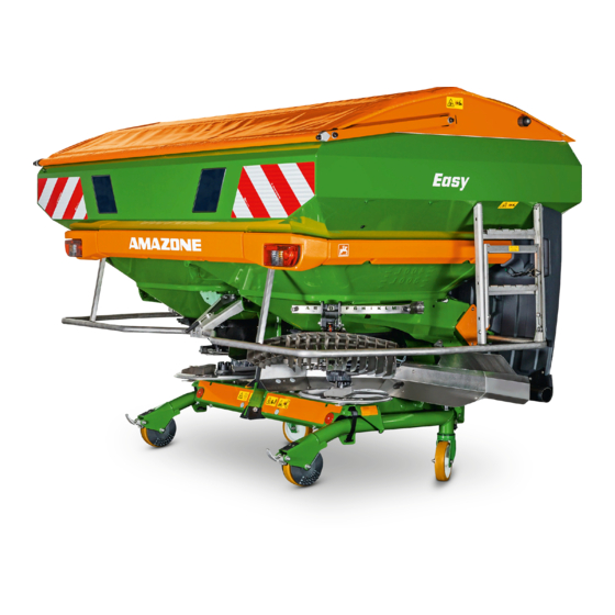
ZA-V
ZA-V Easy
ZA-V Control
ZA-V Tronic
ZA-V Hydro
Mounted spreader
Please read this operating
manual before first
commissioning.
Keep it in a safe place
for future use.
Related Manuals for Amazone ZA-V Series
Summary of Contents for Amazone ZA-V Series
-
Page 1
Operating Manual ZA-V ZA-V Easy ZA-V Control ZA-V Tronic ZA-V Hydro Mounted spreader Please read this operating manual before first MG4136 commissioning. BAG0087.11 01.20 Keep it in a safe place Printed in Germany for future use. -
Page 2
Reading the instruction Manual and following it should seem to be in- convenient and superfluous as it is not enough to hear from others and to realize that a machine is good, to buy it and to believe that now everything should work by itself. -
Page 3
+ 49 (0)5405 501-0 E-mail: amazone@amazone.de Spare part orders Spare parts lists are freely accessible in the spare parts portal at www.amazone.de. Please send orders to your AMAZONE dealer. Formalities of the operating manual Document number: MG4136 Compilation date: 01.20 … -
Page 4
Dear Reader, We update our operating manuals regularly. Your suggestions for improvement help us to create ever more user-friendly manuals. AMAZONEN-WERKE H. DREYER GmbH & Co. KG Postfach 51 D-49202 Hasbergen Tel.: + 49 (0)5405 501-0 E-mail: amazone@amazone.de ZA-V BAG0087.11 01.20… -
Page 5: Table Of Contents
Table of Contents User Information ………………8 Purpose of the document ………………….8 Locations in the operating manual ………………. 8 Diagrams used ……………………. 8 General safety instructions …………….. 9 Obligations and liability ………………….9 Representation of safety symbols ………………11 Organisational measures …………………..
-
Page 6
Table of Contents Dosing slider …………………….. 42 Boundary, ditch and side spreading ………………43 Weighing technology (optional) ………………… 44 PTO shaft ……………………..45 5.8.1 Coupling the PTO shaft ………………….47 5.8.2 Uncoupling the PTO shaft ………………… 48 Hydraulic system connections ………………..49 5.9.1 Coupling the hydraulic hose lines ……………… -
Page 7
Table of Contents 8.8.1 Boundary and side spreading using the Limiter …………106 8.8.2 Boundary spreading by reducing the spreading disc speed ……….108 Switch-on point and switch-off point ………………109 Transportation ………………111 Use of the machine ……………… 112 10.1 Filling the centrifugal broadcaster ……………… -
Page 8: User Information
User Information User Information The User Information section provides information on use of the oper- ating manual. Purpose of the document This operating manual • Describes the operation and maintenance of the machine. • Provides important information on safe and efficient handling of the machine.
-
Page 9: General Safety Instructions
General safety instructions General safety instructions This section contains important information on safe operation of the machine. Obligations and liability Comply with the instructions in the operating manual Knowledge of the basic safety information and safety regulations is a basic requirement for safe handling and fault-free machine operation. Obligations of the operator The operator is obliged only to let those people work with/on the ma- chine who…
-
Page 10
General safety instructions Risks in handling the machine The machine has been constructed to the state-of-the art and the recognised rules of safety. However, there may be risks and re- strictions which occur when operating the machine For the health and safety of the user or third persons, •… -
Page 11: Representation Of Safety Symbols
General safety instructions Representation of safety symbols Safety instructions are indicated by the triangular safety symbol and the highlighted signal word. The signal word (DANGER, WARNING, CAUTION) describes the gravity of the risk and has the following sig- nificance: DANGER Identifies an immediate danger with a high risk that may cause death or serious physical injuries (loss of limbs or long-term damage) if not avoided.
-
Page 12: Organisational Measures
General safety instructions Organisational measures The operator must provide the necessary personal protective equip- ment, such as: Protective glasses • Protective shoes • Protective suit • Skin protection agents, etc. • The operation manual • Must always be kept at the place at which the machine is oper- ated.
-
Page 13: User Training
General safety instructions User training Only those people who have been trained and instructed may work with/on the machine. The operator must clearly specify the responsi- bilities of the people charged with operation, maintenance and repair work. People being trained may only work with/on the machine under the supervision of an experienced person.
-
Page 14: Safety Measures In Normal Operation
General safety instructions Safety measures in normal operation Only operate the machine if all the safety and protection equipment is fully functional. Check the machine at least once a day for visible damage and check the function of the safety and protection equipment. Danger from residual energy Note that there may be residual mechanical, hydraulic, pneumatic and electrical/electronic energy on the machine.
-
Page 15: Spare And Wear Parts And Aids
Immediately replace any machine parts which are not in a perfect state. Only use AMAZONE spare and wear parts released by AMAZONEN- WERKE, so that the type approval remains valid according to the national and international regulations. The use of wear and spare parts from third parties does not guarantee that they have been con- structed in a way as to meet the requirements placed on them.
-
Page 16: Warning Pictograms And Other Signs On The Machine
General safety instructions 2.13 Warning pictograms and other signs on the machine Always keep all the warning pictograms of the machine clean and in a legible state. Replace illegible warning pictograms. You can obtain the warning pictograms from your dealer using the order number (e.g. MD 075).
-
Page 17: Positions Of Warning Symbols And Other Labels
General safety instructions 2.13.1 Positions of warning symbols and other labels Warning symbols The following diagrams show the arrangement of the warning symbols on the machine. Fig. 1 ZA-V BAG0087.11 01.20…
-
Page 18: Positions Of Warning Pictograms And Other Labels
General safety instructions 2.13.2 Positions of warning pictograms and other labels Order number and explanation Warning pictograms MD 075 Danger to fingers or hands from moving op- erating elements due to cutting or cutting off. In these cases there is a danger of extremely serious injuries leading to the loss of body parts such as fingers or hands.
-
Page 19
General safety instructions MD 083 Danger of your arm or upper torso being drawn in or caught by power driven, unpro- tected machine elements! This danger can cause extremely serious injuries to the arm or upper torso. Never open or remove protective devices from driven machinery as long as the tractor engine is running with •… -
Page 20
General safety instructions MD 096 Danger due to escaping high-pressure hy- draulic fluid which can penetrate the body through the skin (danger of infection). This danger can cause serious injuries with long- term damage. Read and observe the information in the operat- ing manual before carrying out repair work on the hydraulic system. -
Page 21
General safety instructions MD 102 Danger for the operator from unintentional starting and rolling during intervention in the machine, e.g. when carrying out installation work, adjustments, troubleshooting, cleaning or repairs. The potential dangers could result in extremely serious and possibly fatal injuries to the entire body. -
Page 22: Dangers If The Safety Information Is Not Observed
General safety instructions 2.14 Dangers if the safety information is not observed Non-compliance with the safety information • Can pose both a danger to people and also to the environment and machine. Can lead to the loss of all warranty claims. •…
-
Page 23: Safety Information For Users
General safety instructions 2.16 Safety information for users WARNING Risk of contusions, cuts, dragging, catching or knocks from in- sufficient traffic and operational safety. Before starting up the machine and the tractor, always check their traffic and operational safety. 2.16.1 General safety and accident prevention information Beside these instructions, comply with the general valid national •…
-
Page 24
General safety instructions When coupling and uncoupling machines, move the support • equipment (if available) to the appropriate position (stability). • When actuating the support equipment, there is a danger of inju- ry from contusion and cutting points! Be particularly careful when coupling the machine to the tractor •… -
Page 25
General safety instructions Machine transportation Comply with the national road traffic regulations when using • public highways. Before moving off, check: • ο The correct connection of the supply lines ο The lighting system for damage, function and cleanliness The brake and hydraulic system for visible damage ο… -
Page 26: Hydraulic System
Replace the hydraulic hose line if it is damaged or worn. Only • use original AMAZONE hydraulic hose lines. • The hydraulic hose lines should not be used for longer than six years, including any storage time of maximum two years. Even…
-
Page 27: Electrical System
General safety instructions 2.16.3 Electrical system When working on the electrical system, always disconnect the • battery (negative terminal). • Only use the prescribed fuses. Using unsuitable fuses will de- stroy the electrical system — risk of fire. Ensure that the battery is connected correctly — firstly connect the •…
-
Page 28
General safety instructions Before switching on the universal joint shaft, check that the se- • lected universal joint shaft speed of the tractor matches the per- mitted drive rev. speed of the machine. Instruct people to leave the danger area of the machine before •… -
Page 29: Fertiliser Spreader Operation
Spare parts must meet at least the specified technical require- • ments of AMAZONEN-WERKE. This is ensured through the use of original AMAZONE spare parts. ZA-V BAG0087.11 01.20…
-
Page 30: Loading And Unloading
Loading and unloading Loading and unloading WARNING Danger from crushing and / or impacts due to unintentional dropping of the raised machine! • It is essential to use the marked lashing points for securing load supporting devices if you are loading or unloading the machine with lifting gear.
-
Page 31: Product Description
Product description Product description Overview of subassemblies Fig. 3 (1) Frame (2) Hopper (3) Spray protection (4) Spreading discs with spreading vanes (5) Setting lever for manual spread rate adjustment (6) Limiter (7) Folding ladder (Option with extension S) ZA-V BAG0087.11 01.20…
-
Page 32: Safety And Protection Equipment
Product description Safety and protection equipment (8) Shaft guard between the input shaft and angular gearbox to pro- tect against the rotating shaft (9) Guard tube as protection against contact with driven spreading discs (10) Guard screen in the hopper as protection against the rotating agitator (11) Shield plates as protection against fertiliser grains that are thrown off to the front…
-
Page 33: Transportation Equipment
Product description Transportation equipment Rear traffic light kit, Fig. 5/… (1) rear lights, brake lights and direction indica- tors (2) warning signs (3) red reflectors (4) side reflectors Front traffic light kit Fig. 5 Fig. 6/… (1) side lights and direction indicators (2) front warning signs (3) One additional warning sign on each side in France.
-
Page 34: Intended Use
Compliance with all the instructions in this operating manual. • Execution of inspection and maintenance work. • Exclusive use of original AMAZONE spare parts. Other uses to those specified above are forbidden and shall be con- sidered as improper. For any damage resulting from improper use: the operator bears the sole responsibility, •…
-
Page 35: Rating Plate And Ce Marking
Product description No-one may stand in the machine danger area: • as long as the tractor engine is running with a connected cardan shaft / hydraulic system. as long as the tractor and machine are not protected against • unintentional start-up and running. The operating person may only move the machine or switch or drive the tools from the transport position to the working position or vice- versa when there is no-one in the machine danger area.
-
Page 36: Technical Data
Product description 4.10 Technical data Hopper Weight Fill level Filling Total Total Extension ZA-V volume width width length (option)** [kg] [mm] [mm] [mm] [mm] ZA-V Special Payload 2200 kg ZA-V 1400 1400 1130 2205 2590 1493 S 600 ZA-V 1700 1700 1155 2205…
-
Page 37: Permitted Mounting Category
Product description Drive rev. speed of the spreading PTO shaft speed disc Mounting height (Tronic) Working width ZA-TS [mm] [mm] [min [min Special V-Set 1: Standard: Standard: 10 – 21 Super V-Set 2: Super Profis 18 – 28 Maximum per- Maximum per- V-Set 3: missible:…
-
Page 38: Necessary Tractor Equipment
Product description 4.12 Necessary tractor equipment For proper machine operation, the tractor must fulfil the following re- quirements: Tractor engine power from 65 kW (90 bhp) upwards Electrical system Battery voltage: • 12V (Volt) Lighting socket: 7-pin • Hydraulic system Maximum operating pressure: •…
-
Page 39: Structure And Function
The following section provides information on the machine structure and the functions of the individual components. Function The AMAZONE ZA-V fertiliser spreader is equipped with two hopper tips and replaceable spreading discs (Fig. 7/1) that are driven from the inside out in opposite directions and counter to the direction of travel, and are equipped with one short (Fig.
-
Page 40: Guard And Function Screens In The Hopper (Protective Device)
Structure and function Guard and function screens in the hopper (protective device) Fig. 9 Di The foldable guard and function screens cover the entire hopper and serve as protection against accidental contact with the rotating agitator • spiral. Protecting from foreign particles and fertiliser clods. •…
-
Page 41: Spreading Discs With Spreading Vanes
Structure and function Spreading discs with spreading vanes An infinite adjustment of the working widths is possible by swivelling the spreading vanes onto the • spreading discs, replacing the spreading vanes on the • spreading discs. In the case of the ZA-V, the spreading discs and agitators are powered by the PTO shaft via the middle gearbox and angular gearbox.
-
Page 42: Agitator
Structure and function Agitator The spiral agitators (Fig. 14/1) in the hopper tips ensure uniform fertiliser flow to the spreading discs. The slow-rotating, spiral-shaped segments of the agitator carry the fertiliser evenly to the corresponding outlet opening. The PTO shaft is responsible for the drive. The speed reduction is attained by means of a free- wheel.
-
Page 43: Boundary, Ditch And Side Spreading
Structure and function Boundary, ditch and side spreading Limiter If the first tramline is half the working width of the field edge, you can carry out boundary spreading via remote control using the Limiter. For this, the limiter can be lowered into the spreading area and thereby influence the spread pattern.
-
Page 44: Weighing Technology (Optional)
Structure and function Weighing technology (optional) (1) Weighing frame (2) Weighing cell (3) Horizontally aligned tie rod The fertiliser spreader makes it possible, with the aid of weighing technology, to determine exactly the fertiliser spread quantity. Likewise, an exact metering can be ensured without a calibration test.
-
Page 45: Pto Shaft
Structure and function PTO shaft For machines with mechanical spreading disc drives, the drive shaft transmits the power from the tractor to the machine. Drive shaft with friction clutch (910 mm) Maximum speeds which briefly occur from approx. 400 Nm, that can occur, e.g., when switching on the PTO shaft, are limited by the fric- tion clutch.
-
Page 46
Structure and function WARNING Danger of trapping and entrapment by unguarded PTO shaft or damaged safety devices! Before all use, check that • ο all PTO shaft protective devices are installed and fully func- tional. the clearance around the PTO shaft is sufficient in all oper- ο… -
Page 47: Coupling The Pto Shaft
Structure and function 5.8.1 Coupling the PTO shaft WARNING Danger from crushing or impact if there is insufficient clearance when coupling the PTO shaft! Couple the PTO shaft with the tractor before coupling the machine with the tractor. This will ensure the necessary clearance for safe coupling of the PTO shaft.
-
Page 48: Uncoupling The Pto Shaft
Structure and function 5.8.2 Uncoupling the PTO shaft WARNING Danger from crushing or impact if there is insufficient clearance when uncoupling the PTO shaft! First uncouple the machine from the tractor before uncoupling the PTO shaft from the tractor. This will ensure the necessary clearance for safe uncoupling of the PTO shaft.
-
Page 49: Hydraulic System Connections
Structure and function Hydraulic system connections All hydraulic hose lines are equipped with grips. • Coloured markings with a code number or code letter have been applied to the gripping sections in order to assign the respective hydraulic function to the pressure line of a tractor control unit! Films are stuck on the implement for the markings that illustrate the respective hydraulic function.
-
Page 50: Coupling The Hydraulic Hose Lines
Structure and function Hydro: single- Permanent oil circulation acting Pressure-free return flow Load-Sensing-control line (where required / settings on the hydraulic block) Maximum permissible pressure in oil return: 10 bar Therefore do not connect the oil return to the tractor control unit, but to a pressure-free oil return flow with a large plug coupling.
-
Page 51: Uncoupling The Hydraulic Hose Lines
Structure and function Observe the maximum approved hydraulic operating pressure of • 210 bar. • Check the compatibility of the hydraulic fluids before connecting the machine to the hydraulic system of your tractor. Do not mix any mineral oils with biological oils. •…
-
Page 52: Three-Point Hitch Frame
Structure and function 5.10 Three-point hitch frame ZA — Ultra: (1) Upper coupling point and lower coupling points. (2) Turning pins for mounting on the tractor with Category 2 or 3 coupling points with linch pin for securing. Fig. 21 ZA — Super: (1) Upper coupling point and lower coupling points.
-
Page 53
Structure and function ZA — Ultra quick hitch: (1) Upper coupling point and lower coupling points (2) Lower link turning pins for mounting on the tractor with Category 3 or 4N coupling points with linch pin for securing. (3) Top link pins for mounting on the tractor with Category 3 cou- pling points with linch pin for securing. -
Page 54: Setting Chart
Setting chart All commercially available types of fertiliser are spread in the AMAZONE spreading hall and the setting data determined in this manner are included in the setting chart. The types of fertiliser listed in the setting chart were in a perfect state when determining the val- ues.
-
Page 55
If you cannot definitively assign the fertiliser to a kind listed in the setting chart • the AMAZONE Fertiliser Service will assist you over the tele- phone in assigning the fertilisers and setting recommendations. +49 (0) 54 05 / 501 111 please consult the contact partner in your country •… -
Page 56
Structure and function Settings Side sprea- Boundary spreading Ditch spreading ding 18,0 17/46 -220 24,0 17/46 -220 28,0 18/47 -220 27,0 14/46 -220 32,0 15/46 -220 36,0 15/48 -220 Operate settings… ZA-V BAG0087.11 01.20… -
Page 57
Structure and function Symbols and units: Fit spreading vane units V-Set1, 2 or 3 onto the spreading disc for one working width spectrum each Working width in m (metre) Spreading vane position Spreader disc speed in rpm depending on the type of spreading Limiter position Half the working width in metres Side spreading… -
Page 58: Control Computer / Operating Terminal Isobus
Structure and function 5.12 Control computer / Operating terminal ISOBUS When using the machine with control computer, it is essential to refer to the operating manual for the Control computer! With the control computer / operating terminal the machine can be conveniently controlled, operated and monitored.
-
Page 59: Control Computer Easyset
Structure and function 5.14 Control computer EasySet (1) Switch On and Off button After being switched on, the display shows the set shutter position (2) Display (3) Function keys Some with LED for showing the activated function Fig. 25 5.14.1 Switch on After switching on, a check is run to see if the real shutter position corresponds to the…
-
Page 60
Structure and function Spread rate setting The spread rate setting is performed separately for the left and right shutters. Read the value for the shutter position for rate settings (0 to 62) from the setting chart or use the result from the spread rate check. Enter the values for the shutter position before operation. -
Page 61
Structure and function Limiter actuation Read the value for adjusting the angle of the limiter (0-100) from the setting chart. Enter the value for the tilt of the limiter before operation. The value can be changed during operation. Lift the limiter for normal spreading / lower for boundary spreading. -
Page 62: Connection
Structure and function 5.14.3 Connection Store the control computer in a dry place when you remove it from the tractor cab. Fig. 31 5.14.4 Error messages Error messages are identified with an E (error). E06 — The left setting motor is not reacting •…
-
Page 63: Easyset Calibration
Structure and function 5.14.5 EasySet calibration EasySet must be calibrated in the following situations: • After working on the base plate or replacing the metering motor. • If the desired and actual spread rate do not concur. 1. Disengage motor. 2.
-
Page 64: Calibration Kit (Option)
Structure and function 5.15 Calibration kit (option) Using the calibration kit, the operating terminal can determine the calibration factor of the ferti- lizer. The calibration factor and the application rate set are used to calculate the necessary shutter posi- tion. Refer to the software operating manual Imple- ment control.
-
Page 65: Transport And Parking Device
Structure and function 5.17 Transport and parking device CAUTION Risk of tipping When setting down the fertilizer spreader, only a small residual amount may be found in the hopper. The transport and parking device enables easy coupling to the trac- tor’s three-point linkage and easy manoeuvring in the yard and in- doors.
-
Page 66
Structure and function Special WARNING When installing/removing the transportation device, secure the raise machine against unintended lowering. Fig. 42 Installation/removal of transportation device: 1. Couple the machine to the tractor. 2. Raise the machine with the tractor’s hydraulic system. 3. Secure the machine against unintentional starting and uninten- tional rolling away. -
Page 67: Border Spreading Deflector And Bed Spreading Deflector
Structure and function 5.18 Border spreading deflector and bed spreading deflector The border spreading deflector and the bed spreading deflector are installed between the spreading discs and influence the spread fans such that border spreading or bed spreading is possible. (1) Hand lever to operate the spreading deflec- tor.
-
Page 68: Three-Way Control (Optional)
Structure and function 5.19 Three-way control (optional) Hose identification Shutter right green Yellow Shutter left blue Limiter The three-way-control is necessary for hydraulic single slider actuation with • tractors with only a double-acting tractor control unit and use of Limiter M. •…
-
Page 69
Structure and function Half-sided spreading with three-way control 1. Keep actuating lever for slide gate of side not for spreading closed. 2. Close the actuating lever (Fig. 40/3) for Limiter M. 3. Open actuating lever for slide gate of side for spreading. 4. -
Page 70: Easycheck (Option)
Afterwards, the collection mats are photographed using the smartphone. The app checks the lat- eral distribution using the photos. If necessary, changes to the settings are sug- gested. Use the AMAZONE homepage to download the following: • EasyCheck app •…
-
Page 71: Camera System (Option)
Structure and function 5.22 Camera system (option) WARNING Risk of injury or even death. If the camera display alone is used for manoeuvring, persons or objects can be overlooked. The camera system is an aid. It does not replace the operator’s awareness of the immediate surroundings. Before manoeuvring, ensure that there are no people or •…
-
Page 72: Implement Mounted On The Front Of The Tractor
Structure and function 5.23 Implement mounted on the front of the tractor Prerequisites for front mounting: • Hydraulic spreading disc drive • ISOBUS control terminal (select front spreader, the left and right shutters are then exchanged in the software) Regulating restrictions in the field of view by the lifting height of the front hopper Road transport: Prevent restrictions in the field of view by maintaining the lifting •…
-
Page 73: Commissioning
Commissioning Commissioning This section contains information • on commissioning your machine. • on checking how you may connect the machine to your tractor. • Before operating the machine for the first time the operator must have read and understood the operating manual. Observe the following chapters •…
-
Page 74: Checking The Suitability Of The Tractor
Commissioning Checking the suitability of the tractor WARNING Danger of breaking during operation, insufficient stability and insufficient tractor steering and braking power on improper use of the tractor! • Check the suitability of your tractor, before connecting the ma- chine to the tractor. You may only connect the machine to tractors suitable for the purpose.
-
Page 75
Commissioning 6.1.1.1 Data required for the calculation Fig. 49 [kg] Empty tractor weight See tractor operating manual or vehicle [kg] Front axle load of the empty tractor documentation [kg] Rear axle load of the empty tractor [kg] Total weight of rear-mounted machine or See technical data for machine or rear bal- rear ballast last… -
Page 76
Commissioning 6.1.1.2 Calculation of the required minimum ballasting at the front G of the tractor to en- V min sure steering capability • − • • • Enter the numeric value for the calculated minimum ballast G V min required on the front side of the tractor, in the table (section 6.1.1.7). 6.1.1.3 Calculation of the actual front axle load of the tractor T V tat… -
Page 77
Commissioning 6.1.1.7 Table Actual value according to Approved value ac- Double approved calculation cording to tractor load capacity (two instruction manual tyres) Minimum ballast front / rear Total weight ≤ Front axle load ≤ ≤ Rear axle load ≤ ≤ •… -
Page 78: Adjusting The Length Of The Pto Shaft To The Tractor
Commissioning Adjusting the length of the PTO shaft to the tractor WARNING Danger from damaged and/or destroyed, flying parts if the PTO shaft is upended or pulls apart while the machine coupled to the tractor is being raised/lowered because the length of the PTO shaft has not been adjusted properly.
-
Page 79
Commissioning The PTO shaft is at its shortest when it is horizontally. The PTO shaft is at its longest when the machine is fully lifted. 1. Couple the tractor to the machine (do not connect the PTO shaft). 2. Apply the tractor’s parking brake. 3. -
Page 80: Securing The Tractor / Machine Against Unintentional Start-Up And Rolling
Commissioning Securing the tractor / machine against unintentional start-up and roll- WARNING Danger of crushing, shearing, cutting, entrapment, entangle- ment, being drawn in, caught or struck during all interventions in the machine. Due to powered operating elements. • Due to unintentional actuation of operating elements or •…
-
Page 81: Adjusting The Hydraulic System With The System Setting Screw
Commissioning Adjusting the hydraulic system with the system setting screw ZA-V Hydro • Be sure to match the hydraulic systems of the tractor and the implement. • The implement hydraulic system is adjusted using the system setting screw on the hydraulic block of the implement. Elevated hydraulic oil temperatures are the result of incorrect •…
-
Page 82
Commissioning (1) Open-Center hydraulic system with con- stant flow pump (gear pump) or setting pump. Put the system setting screw in position A. → Setting pump: Set the maximum required oil quantity on the tractor control unit. If the oil quantity is insufficient, correct functioning of the implement cannot be ensured. -
Page 83: Coupling And Uncoupling The Machine
Coupling and uncoupling the machine Coupling and uncoupling the machine When coupling and decoupling the machine, comply with the chapter «Safety information for the user», page 23. WARNING Danger from crushing, catching, entanglement and / impacts caused by unintentional starting and rolling of the tractor when the tractor’s PTO shaft and supply lines are coupled or decou- pled! Secure the tractor and machine against unintentional start-up and…
-
Page 84: Coupling The Machine
Coupling and uncoupling the machine Coupling the machine WARNING Danger from crushing and / or impacts when coupling the ma- chine between the tractor and the machine! Instruct people to leave the danger area between the tractor and the machine before you approach the machine. Any helpers may only act as guides standing next to the tractor and the machine, and may only move between the vehicles when both are at a standstill.
-
Page 85
Coupling and uncoupling the machine WARNING Risk of energy supply failure between the tractor and the ma- chine through damaged power lines! During coupling, check the course of the power lines. The power lines • must give slightly without tension, bending or rubbing on all movements of the connected machine. -
Page 86: Uncoupling The Machine
Coupling and uncoupling the machine 9. From the tractor seat, couple the upper link to the top attach- ment point of the three-point attachment frame using the top link hook. → The top link hooks lock automatically. 10. Perform a visual inspection to ensure that the upper and lower link hooks are correctly locked before reversing the tractor.
-
Page 87
Coupling and uncoupling the machine Fig. 53 1. Always place the machine with empty hopper on a horizontal storage space with a solid base. 2. Always check for visible damage when uncoupling the machine. See the chapter «Obligation of operator» on page 9. 3. -
Page 88: Adjustments
Adjustments Adjustments When performing any adjustment work on the machine, observe the information in the following chapters «Warning pictograms and other labels on the machine» from • page 16 and «Safety information for the operator» from page 23. • Observing this information is important for your safety. WARNING Danger of, shearing, cutting, entrapment, entanglement, being drawn in, caught or struck during all adjustment work on the…
-
Page 89
Adjustments All settings on the machine are made on the basis of the setting chart for the corresponding fertilizer. • Pay attention to the grain diameter and bulk densi- The calibration factor can be used as a starting value for fertilizer •… -
Page 90: Adjusting The Mounting Height
Adjustments Adjusting the mounting height WARNING Danger of crushing and / or impact for persons behind / under the fertiliser spreader due to unintentional dropping of the ferti- liser spreader if the top link halves are accidentally rotated apart or tear apart! Make sure no persons are present in the danger area behind or be- low the machine before adjusting the mounting height via the upper link.
-
Page 91: Mounting Height For Late Top Dressing
Adjustments Mounting height for late top dressing Using the tractor’s three-point linkage, set the mounting height of the spreader so that the distance between the grain tips and the spread- ing discs is approx. 25 cm. Fasten the lower link pins in the lower link connections at the bottom if required.
-
Page 92: Setting The Spread Rate
Adjustments Setting the spread rate For the ZA-V with control terminal, see separate operating manual! Setting the spread rate for implements without control terminal Fig. 56 To achieve the desired spread rate, set the slider position via the two setting levers. Determine the required slider position either directly from the setting chart or using the calculating disc rule.
-
Page 93
Adjustments Reading off the slider position from the setting chart The slider position depends on the Types of fertiliser being spread (quantity factor). • Working width [m]. • Working speed [km/h]. • Desired spread rate [kg/ha]. • Extract from setting chart: Shutter position for rate setting kg/ha Width… -
Page 94: Spread Rate Check
Adjustments Spread rate check See operating manual for the ISOBUS software / Calibrate fertiliser section. Alternatively, the spread rate check is: ZA-V Profis • carried out at the beginning of the spread- ing process (the calibration factors are measured while spreading the first 200 kg of fertiliser).
-
Page 95: Preparations For The Spread Rate Check With The Fertiliser Chute
Adjustments Spread rate check while standing still It is recommended to perform a spread rate check each time the • fertiliser is changed. • Perform the spread rate check at a standstill with the spreading discs removed and the spreading disc drive switched on. Perform a test run first in order to ensure for continuous fertiliser •…
-
Page 96: Performing A Spread Rate Check With The Fertiliser Chute
Adjustments 8.4.2 Performing a spread rate check with the fertiliser chute 1. Add a sufficient quantity of fertiliser to the hopper. 2. Put the collection bucket under the fertiliser chute 3. Adjust the left shutter position according to the setting chart. 4.
-
Page 97: Determining The Shutter Position With The Sliding Ruler
Adjustments 8.4.4 Determining the shutter position with the sliding ruler The sliding ruler is used to determine the shutter position after per- forming a spread rate check. This is required for implements with manual shutter adjustment using the setting lever and for implements with EasySet. The sliding ruler consists of the covering film and 3 sliding inserts.
-
Page 98
Adjustments Inserts: 1. Slide insert 1 so that the values for the working width and target quantity are lined up on top of each other. 2. Look for the value for the forward speed and read off the desired flow rate written above it 3. -
Page 99
Adjustments For spread rate checks with a calibration device on the side: 1. Slide insert 3 such that the value for the real flow rate (above insert 3) is lined up on top of 2. Look for the value for the desired flow rate (below insert 3) and read off the shutter position to be set above it. -
Page 100: Setting The Spreading Disc Speed
Adjustments Setting the spreading disc speed Take the spreading disc speed for the corresponding fertiliser from the setting chart. Correctly set and maintain the spreading disc speed via the PTO shaft. Hydro: the spreading disc speed must be entered on the control ter- minal.
-
Page 101: Setting The Working Width
Adjustments Setting the working width There are different spreading disc pairs for the various working • widths. • The working widths are adjustable within the working ranges of the respective spreading disc pairs (however, there may be de- viations for the spreading of urea). •…
-
Page 102: Replacing The Spreading Discs
Adjustments 8.6.1 Replacing the spreading discs 1. Loosen the central bolt with the tool. 2. Remove the spreading disc from the gear- box shaft. 3. Put on the other spreading disc. 4. For easier assembly, apply assembly paste (KA059) on the thread of the central bolt. 5.
-
Page 103: Adjusting The Spreading Vane Positions
Adjustments 8.6.2 Adjusting the spreading vane positions Fig. 64 (1) Short spreading vane (2) Adjustment scale (5-25) for short spreading vane (3) Long spreading vane (4) Adjustment scale (35-55) for long spreading vane (5) Adjustment lever for spreading vane (6) Vane locking mechanism as indicator of the vane position The spreading vane position depends on: •…
-
Page 104: Checking The Working Width And Lateral Distribution
Adjustments Adjust the spreading vanes as follows: 1. Switch off the tractor PTO shaft. 2. Secure the tractor against unintentional starting and unintention- al rolling away. 3. Wait until any rotating spreading discs have come to a full stop. 4. Adjust the desired working width on both spreading discs by swivelling the short and long spreading vane.
-
Page 105: Boundary, Ditch And Side Spreading
Adjustments Boundary, ditch and side spreading 1. Boundary spreading in accordance with fertiliser ordinance (Fig. 58): Along the field boundary there is a road, a field path or another person’s lot. Fertiliser is not permitted to fall beyond the Fig. 65 boundaries in accordance with the fertiliser ordi- nance.
-
Page 106: Boundary And Side Spreading Using The Limiter
Adjustments The values in the setting chart are intended as reference values. • Depending on the fertiliser properties and the set spreading vane position, the optimal setting can differ from the values in the setting chart. For this reason, we strongly recommend checking the setting with the mobile test rig.
-
Page 107
Adjustments Adjust according to the type of fertiliser and border distance Fig. 69 1. Pull the adjusting knob (1) and swivel the border spreading de- flector up to the set value on the scale according to the setting chart. 2. Let go of the adjusting knob, so that it catches in the scale. The values in the setting table are intended as guideline values, •… -
Page 108: Boundary Spreading By Reducing The Spreading Disc Speed
Adjustments 8.8.2 Boundary spreading by reducing the spreading disc speed For boundary spreading with the ZA-V Hydro, the spreading disc speed on the boundary side is reduced. Enter the spreading disc speed for boundary spreading on the control terminal. ↓With smaller working widths, the field-side spreading disc speed may also need to be reduced.
-
Page 109: Switch-On Point And Switch-Off Point
Adjustments Switch-on point and switch-off point The switch-on point is the position for opening the shutters • when moving out of the headlands at which the best possible fertiliser distribution is achieved. The switch-off point is the position for closing the shutters •…
-
Page 110
Adjustments Adjusting the switch-off point for the driving style The selection of the switch-off point depends on the driving style on the headlands. • Distribution-optimised driving style With the distribution-optimised driving style, it is not possible to turn into the headland tramline in many cases, as, in particular with small/negative switch-off points, the shutters close too late. -
Page 111: Transportation
Transportation Transportation Comply with the chapter «Safety information for the user», from • page 25 when moving. • Before moving off, check: The correct connection of the supply lines ο ο The lighting system for damage, function and cleanliness The hydraulic system for visible defects ο…
-
Page 112: Use Of The Machine
Use of the machine Use of the machine When using the machine, observe the information in the following sections: «Warning pictograms and other signs on the machine» • «Safety information for the user», on page 23 ff. • Observing this information is important for your safety. WARNING Danger from ejected objects (fertiliser particles, foreign bodies, e.g.
-
Page 113
Use of the machine WARNING Danger from being entangled and drawn in and danger from for- eign objects being caught and thrown in the danger area of the driven PTO shaft! Whenever the machine is used, first check to ensure that the •… -
Page 114: Filling The Centrifugal Broadcaster
Use of the machine 10.1 Filling the centrifugal broadcaster WARNING Danger of breaking during operation, insufficient stability and insufficient tractor steering and braking power on improper use of the tractor! Comply with the maximum load of the connected machine and the approved axle and support loads of the tractor.
-
Page 115: Spreading Operation
Use of the machine 10.2 Spreading operation The spreading vanes are made of especially hard-wearing stain- • less steel. However, the spreading vanes are wearing parts. • The type of fertiliser, times of use and spread rates influence the service life of spreading vanes. The technical condition of the spreading vanes is essential for •…
-
Page 116
Use of the machine WARNING Danger from breaking age during operation when the overload clutch of the PTO shaft engages (if installed)! Switch off the universal joint shaft of the tractor immediately if the overload clutch of the PTO shaft engages. This avoids damaging the overload clutch. -
Page 117
Use of the machine • Do not open the shutter until you have reached the specified spreader disc speed! Maintain a constant spreading disc speed. • Always carry out a spread rate check or turn on the online cali- • bration at the beginning of the spreading process. -
Page 118: Notes For Spreading Slug Pellets (E.g. Mesurol)
Use of the machine 10.3 Notes for spreading slug pellets (e.g. Mesurol) The standard model ZA-V can also be used for wide-area spreading of slug pellets. The slug pellets (e.g. Mesurol) may either be pellets or have a pellet-like shape and are spread in relatively small quantities (e.g.
-
Page 119: Complete Discharging
Use of the machine 10.4 Complete discharging DANGER Risk of injury from rotating spreader discs. Do not drive spreader discs to remove any residue. WARNING Danger of being caught and drawn in with driven agitator! Never open the guard and function screen while the tractor en- •…
-
Page 120: Faults
Faults Faults WARNING Risk of contusions, shearing, cutting, catching, entanglement drawing in and knocks through Unintentional falling of the machine raised using the trac- • tor’s three-point linkage. Unintentional falling of raised, unsecured machine parts. • Unintentional start-up and rolling of the tractor-machine •…
-
Page 121: Faults, Causes And Remedies
Replaced defective or worn parts immediately. The spreading properties of your Contact the fertiliser differ from those of the AMAZONE Fertiliser Service. one we tested when creating the setting chart. +49 5405 501-111 Too much fertiliser in the overlap Prescribed spreading disc speed Reduce tractor engine speed.
-
Page 122: Cleaning, Maintenance And Repairs
Cleaning, maintenance and repairs Cleaning, maintenance and repairs WARNING Risk of contusions, shearing, cutting, catching, entanglement drawing in and knocks through Unintentional falling of the machine raised using the trac- • tor’s three-point linkage. Unintentional falling of raised, unsecured machine parts. •…
-
Page 123: Cleaning
Cleaning, maintenance and repairs 12.1 Cleaning Pay particular attention to the brake, air and hydraulic hose • lines. • Never treat brake, air and hydraulic hose lines with benzene, benzole, petroleum or mineral oils. After cleaning, grease the machine, in particular after cleaning •…
-
Page 124: Lubrication Instructions
Cleaning, maintenance and repairs 12.2 Lubrication instructions Lubricants For lubrication, use a lithium saponified, multipurpose grease with EP additives: Company Lubricant designation Normal use conditions Extreme use conditions ARAL Aralub HL 2 Aralub HLP 2 FINA Marson L2 Marson EPL-2 ESSO Beacon 2 Beacon EP 2…
-
Page 125: Maintenance Plan — Overview
Cleaning, maintenance and repairs 12.3 Maintenance plan – Overview Carry out maintenance work when the first interval is reached. • The times, continuous services or maintenance intervals of any • third party documentation shall have priority. Once after 50 operating hours Component Servicing work See page…
-
Page 126: Oil Change Angular Gearbox
Cleaning, maintenance and repairs 12.4 Oil change angular gearbox 1. Dismantle the transport device if necessary. Maintain the tension in the extension spring by inserting a retaining screw in the frame, swivel the transport device up and disman- tle. 2. Dismantle the cover underneath the gearbox.
-
Page 127: Replacing The Spreading Vanes
Cleaning, maintenance and repairs 12.6 Replacing the spreading vanes Fig. 77 When exchanging the spreading vanes, use the assembly paste pro- vided. This is the only way to ensure that the specified tightening torque is sufficient. Required tightening torque: 8,4 Nm The technical condition of the spreading vanes is essential for •…
-
Page 128: Taring The Spreader
Cleaning, maintenance and repairs 12.7 Taring the spreader If the control computer does not show 0 kg (+/- 5 kg) fill weight with the spreader empty, the spreader must be retared (see control computer operating manual). This may occur, for example, after the attachment of special accesso- ries.
-
Page 129: Hydraulic System
Cleaning, maintenance and repairs 12.9 Hydraulic system WARNING Danger due to escaping high-pressure hydraulic fluid which can penetrate the body through the skin (danger of infection). Only a specialist workshop may carry out work on the hydraulic • system. • The hydraulic system is under high pressure.
-
Page 130: Labelling Of Hydraulic Hose Lines
Replace the hydraulic hose line if it is damaged or worn. Only • use original AMAZONE hydraulic hose lines. • The hydraulic hose lines should not be used for longer than six years, including any storage time of maximum two years. Even…
-
Page 131: Maintenance Intervals
Cleaning, maintenance and repairs 12.9.2 Maintenance intervals After the first 10 operating hours, and then every 50 operating hours 1. Check all the components of the hydraulic system for tightness. 2. If necessary, tighten screw unions. Before each start-up: 1. Check hydraulic hose lines for visible damage. 2.
-
Page 132: Installation And Removal Of Hydraulic Hose Lines
12.9.4 Installation and removal of hydraulic hose lines When installing and removing hydraulic hose lines, always observe the following information: Only use original AMAZONE hydraulic hose lines. • Ensure cleanliness. • Always install the hydraulic hose lines to ensure the following in •…
-
Page 133: Upper And Lower Link Pins
Cleaning, maintenance and repairs 12.10 Upper and lower link pins WARNING Risk of contusions, catching, and knocks when the machine is unexpectedly released from the tractor! Check the upper and lower link pins for visible damage each time you couple the machine. Replace the upper and lower link pins in the event of clearly visible wear.
-
Page 134: Screw Tightening Torques
Cleaning, maintenance and repairs 12.11 Screw tightening torques 10.9 12.9 M 8×1 M 10 16 (17) M 10×1 M 12 18 (19) M 12×1,5 M 14 M 14×1,5 M 16 M 16×1,5 M 18 M 18×1,5 M 20 M 20×1,5 M 22 M 22×1,5 1050…
-
Page 135: Hydraulic Diagram
Hydraulic diagram ZA-V Hydro Fig. 80 ZA-V BAG0087.11 01.20…
-
Page 1
Operating Manual ZA-V ZA-V Easy ZA-V Control ZA-V Tronic ZA-V Hydro Mounted spreader Please read this operating manual before first MG4136 commissioning. BAG0087.11 01.20 Keep it in a safe place Printed in Germany for future use. -
Page 2
Reading the instruction Manual and following it should seem to be in- convenient and superfluous as it is not enough to hear from others and to realize that a machine is good, to buy it and to believe that now everything should work by itself. -
Page 3
+ 49 (0)5405 501-0 E-mail: amazone@amazone.de Spare part orders Spare parts lists are freely accessible in the spare parts portal at www.amazone.de. Please send orders to your AMAZONE dealer. Formalities of the operating manual Document number: MG4136 Compilation date: 01.20 … -
Page 4
Dear Reader, We update our operating manuals regularly. Your suggestions for improvement help us to create ever more user-friendly manuals. AMAZONEN-WERKE H. DREYER GmbH & Co. KG Postfach 51 D-49202 Hasbergen Tel.: + 49 (0)5405 501-0 E-mail: amazone@amazone.de ZA-V BAG0087.11 01.20… -
Page 5: Table Of Contents
Table of Contents User Information ………………8 Purpose of the document ………………….8 Locations in the operating manual ………………. 8 Diagrams used ……………………. 8 General safety instructions …………….. 9 Obligations and liability ………………….9 Representation of safety symbols ………………11 Organisational measures …………………..
-
Page 6
Table of Contents Dosing slider …………………….. 42 Boundary, ditch and side spreading ………………43 Weighing technology (optional) ………………… 44 PTO shaft ……………………..45 5.8.1 Coupling the PTO shaft ………………….47 5.8.2 Uncoupling the PTO shaft ………………… 48 Hydraulic system connections ………………..49 5.9.1 Coupling the hydraulic hose lines ……………… -
Page 7
Table of Contents 8.8.1 Boundary and side spreading using the Limiter …………106 8.8.2 Boundary spreading by reducing the spreading disc speed ……….108 Switch-on point and switch-off point ………………109 Transportation ………………111 Use of the machine ……………… 112 10.1 Filling the centrifugal broadcaster ……………… -
Page 8: User Information
User Information User Information The User Information section provides information on use of the oper- ating manual. Purpose of the document This operating manual • Describes the operation and maintenance of the machine. • Provides important information on safe and efficient handling of the machine.
-
Page 9: General Safety Instructions
General safety instructions General safety instructions This section contains important information on safe operation of the machine. Obligations and liability Comply with the instructions in the operating manual Knowledge of the basic safety information and safety regulations is a basic requirement for safe handling and fault-free machine operation. Obligations of the operator The operator is obliged only to let those people work with/on the ma- chine who…
-
Page 10
General safety instructions Risks in handling the machine The machine has been constructed to the state-of-the art and the recognised rules of safety. However, there may be risks and re- strictions which occur when operating the machine For the health and safety of the user or third persons, •… -
Page 11: Representation Of Safety Symbols
General safety instructions Representation of safety symbols Safety instructions are indicated by the triangular safety symbol and the highlighted signal word. The signal word (DANGER, WARNING, CAUTION) describes the gravity of the risk and has the following sig- nificance: DANGER Identifies an immediate danger with a high risk that may cause death or serious physical injuries (loss of limbs or long-term damage) if not avoided.
-
Page 12: Organisational Measures
General safety instructions Organisational measures The operator must provide the necessary personal protective equip- ment, such as: Protective glasses • Protective shoes • Protective suit • Skin protection agents, etc. • The operation manual • Must always be kept at the place at which the machine is oper- ated.
-
Page 13: User Training
General safety instructions User training Only those people who have been trained and instructed may work with/on the machine. The operator must clearly specify the responsi- bilities of the people charged with operation, maintenance and repair work. People being trained may only work with/on the machine under the supervision of an experienced person.
-
Page 14: Safety Measures In Normal Operation
General safety instructions Safety measures in normal operation Only operate the machine if all the safety and protection equipment is fully functional. Check the machine at least once a day for visible damage and check the function of the safety and protection equipment. Danger from residual energy Note that there may be residual mechanical, hydraulic, pneumatic and electrical/electronic energy on the machine.
-
Page 15: Spare And Wear Parts And Aids
Immediately replace any machine parts which are not in a perfect state. Only use AMAZONE spare and wear parts released by AMAZONEN- WERKE, so that the type approval remains valid according to the national and international regulations. The use of wear and spare parts from third parties does not guarantee that they have been con- structed in a way as to meet the requirements placed on them.
-
Page 16: Warning Pictograms And Other Signs On The Machine
General safety instructions 2.13 Warning pictograms and other signs on the machine Always keep all the warning pictograms of the machine clean and in a legible state. Replace illegible warning pictograms. You can obtain the warning pictograms from your dealer using the order number (e.g. MD 075).
-
Page 17: Positions Of Warning Symbols And Other Labels
General safety instructions 2.13.1 Positions of warning symbols and other labels Warning symbols The following diagrams show the arrangement of the warning symbols on the machine. Fig. 1 ZA-V BAG0087.11 01.20…
-
Page 18: Positions Of Warning Pictograms And Other Labels
General safety instructions 2.13.2 Positions of warning pictograms and other labels Order number and explanation Warning pictograms MD 075 Danger to fingers or hands from moving op- erating elements due to cutting or cutting off. In these cases there is a danger of extremely serious injuries leading to the loss of body parts such as fingers or hands.
-
Page 19
General safety instructions MD 083 Danger of your arm or upper torso being drawn in or caught by power driven, unpro- tected machine elements! This danger can cause extremely serious injuries to the arm or upper torso. Never open or remove protective devices from driven machinery as long as the tractor engine is running with •… -
Page 20
General safety instructions MD 096 Danger due to escaping high-pressure hy- draulic fluid which can penetrate the body through the skin (danger of infection). This danger can cause serious injuries with long- term damage. Read and observe the information in the operat- ing manual before carrying out repair work on the hydraulic system. -
Page 21
General safety instructions MD 102 Danger for the operator from unintentional starting and rolling during intervention in the machine, e.g. when carrying out installation work, adjustments, troubleshooting, cleaning or repairs. The potential dangers could result in extremely serious and possibly fatal injuries to the entire body. -
Page 22: Dangers If The Safety Information Is Not Observed
General safety instructions 2.14 Dangers if the safety information is not observed Non-compliance with the safety information • Can pose both a danger to people and also to the environment and machine. Can lead to the loss of all warranty claims. •…
-
Page 23: Safety Information For Users
General safety instructions 2.16 Safety information for users WARNING Risk of contusions, cuts, dragging, catching or knocks from in- sufficient traffic and operational safety. Before starting up the machine and the tractor, always check their traffic and operational safety. 2.16.1 General safety and accident prevention information Beside these instructions, comply with the general valid national •…
-
Page 24
General safety instructions When coupling and uncoupling machines, move the support • equipment (if available) to the appropriate position (stability). • When actuating the support equipment, there is a danger of inju- ry from contusion and cutting points! Be particularly careful when coupling the machine to the tractor •… -
Page 25
General safety instructions Machine transportation Comply with the national road traffic regulations when using • public highways. Before moving off, check: • ο The correct connection of the supply lines ο The lighting system for damage, function and cleanliness The brake and hydraulic system for visible damage ο… -
Page 26: Hydraulic System
Replace the hydraulic hose line if it is damaged or worn. Only • use original AMAZONE hydraulic hose lines. • The hydraulic hose lines should not be used for longer than six years, including any storage time of maximum two years. Even…
-
Page 27: Electrical System
General safety instructions 2.16.3 Electrical system When working on the electrical system, always disconnect the • battery (negative terminal). • Only use the prescribed fuses. Using unsuitable fuses will de- stroy the electrical system — risk of fire. Ensure that the battery is connected correctly — firstly connect the •…
-
Page 28
General safety instructions Before switching on the universal joint shaft, check that the se- • lected universal joint shaft speed of the tractor matches the per- mitted drive rev. speed of the machine. Instruct people to leave the danger area of the machine before •… -
Page 29: Fertiliser Spreader Operation
Spare parts must meet at least the specified technical require- • ments of AMAZONEN-WERKE. This is ensured through the use of original AMAZONE spare parts. ZA-V BAG0087.11 01.20…
-
Page 30: Loading And Unloading
Loading and unloading Loading and unloading WARNING Danger from crushing and / or impacts due to unintentional dropping of the raised machine! • It is essential to use the marked lashing points for securing load supporting devices if you are loading or unloading the machine with lifting gear.
-
Page 31: Product Description
Product description Product description Overview of subassemblies Fig. 3 (1) Frame (2) Hopper (3) Spray protection (4) Spreading discs with spreading vanes (5) Setting lever for manual spread rate adjustment (6) Limiter (7) Folding ladder (Option with extension S) ZA-V BAG0087.11 01.20…
-
Page 32: Safety And Protection Equipment
Product description Safety and protection equipment (8) Shaft guard between the input shaft and angular gearbox to pro- tect against the rotating shaft (9) Guard tube as protection against contact with driven spreading discs (10) Guard screen in the hopper as protection against the rotating agitator (11) Shield plates as protection against fertiliser grains that are thrown off to the front…
-
Page 33: Transportation Equipment
Product description Transportation equipment Rear traffic light kit, Fig. 5/… (1) rear lights, brake lights and direction indica- tors (2) warning signs (3) red reflectors (4) side reflectors Front traffic light kit Fig. 5 Fig. 6/… (1) side lights and direction indicators (2) front warning signs (3) One additional warning sign on each side in France.
-
Page 34: Intended Use
Compliance with all the instructions in this operating manual. • Execution of inspection and maintenance work. • Exclusive use of original AMAZONE spare parts. Other uses to those specified above are forbidden and shall be con- sidered as improper. For any damage resulting from improper use: the operator bears the sole responsibility, •…
-
Page 35: Rating Plate And Ce Marking
Product description No-one may stand in the machine danger area: • as long as the tractor engine is running with a connected cardan shaft / hydraulic system. as long as the tractor and machine are not protected against • unintentional start-up and running. The operating person may only move the machine or switch or drive the tools from the transport position to the working position or vice- versa when there is no-one in the machine danger area.
-
Page 36: Technical Data
Product description 4.10 Technical data Hopper Weight Fill level Filling Total Total Extension ZA-V volume width width length (option)** [kg] [mm] [mm] [mm] [mm] ZA-V Special Payload 2200 kg ZA-V 1400 1400 1130 2205 2590 1493 S 600 ZA-V 1700 1700 1155 2205…
-
Page 37: Permitted Mounting Category
Product description Drive rev. speed of the spreading PTO shaft speed disc Mounting height (Tronic) Working width ZA-TS [mm] [mm] [min [min Special V-Set 1: Standard: Standard: 10 – 21 Super V-Set 2: Super Profis 18 – 28 Maximum per- Maximum per- V-Set 3: missible:…
-
Page 38: Necessary Tractor Equipment
Product description 4.12 Necessary tractor equipment For proper machine operation, the tractor must fulfil the following re- quirements: Tractor engine power from 65 kW (90 bhp) upwards Electrical system Battery voltage: • 12V (Volt) Lighting socket: 7-pin • Hydraulic system Maximum operating pressure: •…
-
Page 39: Structure And Function
The following section provides information on the machine structure and the functions of the individual components. Function The AMAZONE ZA-V fertiliser spreader is equipped with two hopper tips and replaceable spreading discs (Fig. 7/1) that are driven from the inside out in opposite directions and counter to the direction of travel, and are equipped with one short (Fig.
-
Page 40: Guard And Function Screens In The Hopper (Protective Device)
Structure and function Guard and function screens in the hopper (protective device) Fig. 9 Di The foldable guard and function screens cover the entire hopper and serve as protection against accidental contact with the rotating agitator • spiral. Protecting from foreign particles and fertiliser clods. •…
-
Page 41: Spreading Discs With Spreading Vanes
Structure and function Spreading discs with spreading vanes An infinite adjustment of the working widths is possible by swivelling the spreading vanes onto the • spreading discs, replacing the spreading vanes on the • spreading discs. In the case of the ZA-V, the spreading discs and agitators are powered by the PTO shaft via the middle gearbox and angular gearbox.
-
Page 42: Agitator
Structure and function Agitator The spiral agitators (Fig. 14/1) in the hopper tips ensure uniform fertiliser flow to the spreading discs. The slow-rotating, spiral-shaped segments of the agitator carry the fertiliser evenly to the corresponding outlet opening. The PTO shaft is responsible for the drive. The speed reduction is attained by means of a free- wheel.
-
Page 43: Boundary, Ditch And Side Spreading
Structure and function Boundary, ditch and side spreading Limiter If the first tramline is half the working width of the field edge, you can carry out boundary spreading via remote control using the Limiter. For this, the limiter can be lowered into the spreading area and thereby influence the spread pattern.
-
Page 44: Weighing Technology (Optional)
Structure and function Weighing technology (optional) (1) Weighing frame (2) Weighing cell (3) Horizontally aligned tie rod The fertiliser spreader makes it possible, with the aid of weighing technology, to determine exactly the fertiliser spread quantity. Likewise, an exact metering can be ensured without a calibration test.
-
Page 45: Pto Shaft
Structure and function PTO shaft For machines with mechanical spreading disc drives, the drive shaft transmits the power from the tractor to the machine. Drive shaft with friction clutch (910 mm) Maximum speeds which briefly occur from approx. 400 Nm, that can occur, e.g., when switching on the PTO shaft, are limited by the fric- tion clutch.
-
Page 46
Structure and function WARNING Danger of trapping and entrapment by unguarded PTO shaft or damaged safety devices! Before all use, check that • ο all PTO shaft protective devices are installed and fully func- tional. the clearance around the PTO shaft is sufficient in all oper- ο… -
Page 47: Coupling The Pto Shaft
Structure and function 5.8.1 Coupling the PTO shaft WARNING Danger from crushing or impact if there is insufficient clearance when coupling the PTO shaft! Couple the PTO shaft with the tractor before coupling the machine with the tractor. This will ensure the necessary clearance for safe coupling of the PTO shaft.
-
Page 48: Uncoupling The Pto Shaft
Structure and function 5.8.2 Uncoupling the PTO shaft WARNING Danger from crushing or impact if there is insufficient clearance when uncoupling the PTO shaft! First uncouple the machine from the tractor before uncoupling the PTO shaft from the tractor. This will ensure the necessary clearance for safe uncoupling of the PTO shaft.
-
Page 49: Hydraulic System Connections
Structure and function Hydraulic system connections All hydraulic hose lines are equipped with grips. • Coloured markings with a code number or code letter have been applied to the gripping sections in order to assign the respective hydraulic function to the pressure line of a tractor control unit! Films are stuck on the implement for the markings that illustrate the respective hydraulic function.
-
Page 50: Coupling The Hydraulic Hose Lines
Structure and function Hydro: single- Permanent oil circulation acting Pressure-free return flow Load-Sensing-control line (where required / settings on the hydraulic block) Maximum permissible pressure in oil return: 10 bar Therefore do not connect the oil return to the tractor control unit, but to a pressure-free oil return flow with a large plug coupling.
-
Page 51: Uncoupling The Hydraulic Hose Lines
Structure and function Observe the maximum approved hydraulic operating pressure of • 210 bar. • Check the compatibility of the hydraulic fluids before connecting the machine to the hydraulic system of your tractor. Do not mix any mineral oils with biological oils. •…
-
Page 52: Three-Point Hitch Frame
Structure and function 5.10 Three-point hitch frame ZA — Ultra: (1) Upper coupling point and lower coupling points. (2) Turning pins for mounting on the tractor with Category 2 or 3 coupling points with linch pin for securing. Fig. 21 ZA — Super: (1) Upper coupling point and lower coupling points.
-
Page 53
Structure and function ZA — Ultra quick hitch: (1) Upper coupling point and lower coupling points (2) Lower link turning pins for mounting on the tractor with Category 3 or 4N coupling points with linch pin for securing. (3) Top link pins for mounting on the tractor with Category 3 cou- pling points with linch pin for securing. -
Page 54: Setting Chart
Setting chart All commercially available types of fertiliser are spread in the AMAZONE spreading hall and the setting data determined in this manner are included in the setting chart. The types of fertiliser listed in the setting chart were in a perfect state when determining the val- ues.
-
Page 55
If you cannot definitively assign the fertiliser to a kind listed in the setting chart • the AMAZONE Fertiliser Service will assist you over the tele- phone in assigning the fertilisers and setting recommendations. +49 (0) 54 05 / 501 111 please consult the contact partner in your country •… -
Page 56
Structure and function Settings Side sprea- Boundary spreading Ditch spreading ding 18,0 17/46 -220 24,0 17/46 -220 28,0 18/47 -220 27,0 14/46 -220 32,0 15/46 -220 36,0 15/48 -220 Operate settings… ZA-V BAG0087.11 01.20… -
Page 57
Structure and function Symbols and units: Fit spreading vane units V-Set1, 2 or 3 onto the spreading disc for one working width spectrum each Working width in m (metre) Spreading vane position Spreader disc speed in rpm depending on the type of spreading Limiter position Half the working width in metres Side spreading… -
Page 58: Control Computer / Operating Terminal Isobus
Structure and function 5.12 Control computer / Operating terminal ISOBUS When using the machine with control computer, it is essential to refer to the operating manual for the Control computer! With the control computer / operating terminal the machine can be conveniently controlled, operated and monitored.
-
Page 59: Control Computer Easyset
Structure and function 5.14 Control computer EasySet (1) Switch On and Off button After being switched on, the display shows the set shutter position (2) Display (3) Function keys Some with LED for showing the activated function Fig. 25 5.14.1 Switch on After switching on, a check is run to see if the real shutter position corresponds to the…
-
Page 60
Structure and function Spread rate setting The spread rate setting is performed separately for the left and right shutters. Read the value for the shutter position for rate settings (0 to 62) from the setting chart or use the result from the spread rate check. Enter the values for the shutter position before operation. -
Page 61
Structure and function Limiter actuation Read the value for adjusting the angle of the limiter (0-100) from the setting chart. Enter the value for the tilt of the limiter before operation. The value can be changed during operation. Lift the limiter for normal spreading / lower for boundary spreading. -
Page 62: Connection
Structure and function 5.14.3 Connection Store the control computer in a dry place when you remove it from the tractor cab. Fig. 31 5.14.4 Error messages Error messages are identified with an E (error). E06 — The left setting motor is not reacting •…
-
Page 63: Easyset Calibration
Structure and function 5.14.5 EasySet calibration EasySet must be calibrated in the following situations: • After working on the base plate or replacing the metering motor. • If the desired and actual spread rate do not concur. 1. Disengage motor. 2.
-
Page 64: Calibration Kit (Option)
Structure and function 5.15 Calibration kit (option) Using the calibration kit, the operating terminal can determine the calibration factor of the ferti- lizer. The calibration factor and the application rate set are used to calculate the necessary shutter posi- tion. Refer to the software operating manual Imple- ment control.
-
Page 65: Transport And Parking Device
Structure and function 5.17 Transport and parking device CAUTION Risk of tipping When setting down the fertilizer spreader, only a small residual amount may be found in the hopper. The transport and parking device enables easy coupling to the trac- tor’s three-point linkage and easy manoeuvring in the yard and in- doors.
-
Page 66
Structure and function Special WARNING When installing/removing the transportation device, secure the raise machine against unintended lowering. Fig. 42 Installation/removal of transportation device: 1. Couple the machine to the tractor. 2. Raise the machine with the tractor’s hydraulic system. 3. Secure the machine against unintentional starting and uninten- tional rolling away. -
Page 67: Border Spreading Deflector And Bed Spreading Deflector
Structure and function 5.18 Border spreading deflector and bed spreading deflector The border spreading deflector and the bed spreading deflector are installed between the spreading discs and influence the spread fans such that border spreading or bed spreading is possible. (1) Hand lever to operate the spreading deflec- tor.
-
Page 68: Three-Way Control (Optional)
Structure and function 5.19 Three-way control (optional) Hose identification Shutter right green Yellow Shutter left blue Limiter The three-way-control is necessary for hydraulic single slider actuation with • tractors with only a double-acting tractor control unit and use of Limiter M. •…
-
Page 69
Structure and function Half-sided spreading with three-way control 1. Keep actuating lever for slide gate of side not for spreading closed. 2. Close the actuating lever (Fig. 40/3) for Limiter M. 3. Open actuating lever for slide gate of side for spreading. 4. -
Page 70: Easycheck (Option)
Afterwards, the collection mats are photographed using the smartphone. The app checks the lat- eral distribution using the photos. If necessary, changes to the settings are sug- gested. Use the AMAZONE homepage to download the following: • EasyCheck app •…
-
Page 71: Camera System (Option)
Structure and function 5.22 Camera system (option) WARNING Risk of injury or even death. If the camera display alone is used for manoeuvring, persons or objects can be overlooked. The camera system is an aid. It does not replace the operator’s awareness of the immediate surroundings. Before manoeuvring, ensure that there are no people or •…
-
Page 72: Implement Mounted On The Front Of The Tractor
Structure and function 5.23 Implement mounted on the front of the tractor Prerequisites for front mounting: • Hydraulic spreading disc drive • ISOBUS control terminal (select front spreader, the left and right shutters are then exchanged in the software) Regulating restrictions in the field of view by the lifting height of the front hopper Road transport: Prevent restrictions in the field of view by maintaining the lifting •…
-
Page 73: Commissioning
Commissioning Commissioning This section contains information • on commissioning your machine. • on checking how you may connect the machine to your tractor. • Before operating the machine for the first time the operator must have read and understood the operating manual. Observe the following chapters •…
-
Page 74: Checking The Suitability Of The Tractor
Commissioning Checking the suitability of the tractor WARNING Danger of breaking during operation, insufficient stability and insufficient tractor steering and braking power on improper use of the tractor! • Check the suitability of your tractor, before connecting the ma- chine to the tractor. You may only connect the machine to tractors suitable for the purpose.
-
Page 75
Commissioning 6.1.1.1 Data required for the calculation Fig. 49 [kg] Empty tractor weight See tractor operating manual or vehicle [kg] Front axle load of the empty tractor documentation [kg] Rear axle load of the empty tractor [kg] Total weight of rear-mounted machine or See technical data for machine or rear bal- rear ballast last… -
Page 76
Commissioning 6.1.1.2 Calculation of the required minimum ballasting at the front G of the tractor to en- V min sure steering capability • − • • • Enter the numeric value for the calculated minimum ballast G V min required on the front side of the tractor, in the table (section 6.1.1.7). 6.1.1.3 Calculation of the actual front axle load of the tractor T V tat… -
Page 77
Commissioning 6.1.1.7 Table Actual value according to Approved value ac- Double approved calculation cording to tractor load capacity (two instruction manual tyres) Minimum ballast front / rear Total weight ≤ Front axle load ≤ ≤ Rear axle load ≤ ≤ •… -
Page 78: Adjusting The Length Of The Pto Shaft To The Tractor
Commissioning Adjusting the length of the PTO shaft to the tractor WARNING Danger from damaged and/or destroyed, flying parts if the PTO shaft is upended or pulls apart while the machine coupled to the tractor is being raised/lowered because the length of the PTO shaft has not been adjusted properly.
-
Page 79
Commissioning The PTO shaft is at its shortest when it is horizontally. The PTO shaft is at its longest when the machine is fully lifted. 1. Couple the tractor to the machine (do not connect the PTO shaft). 2. Apply the tractor’s parking brake. 3. -
Page 80: Securing The Tractor / Machine Against Unintentional Start-Up And Rolling
Commissioning Securing the tractor / machine against unintentional start-up and roll- WARNING Danger of crushing, shearing, cutting, entrapment, entangle- ment, being drawn in, caught or struck during all interventions in the machine. Due to powered operating elements. • Due to unintentional actuation of operating elements or •…
-
Page 81: Adjusting The Hydraulic System With The System Setting Screw
Commissioning Adjusting the hydraulic system with the system setting screw ZA-V Hydro • Be sure to match the hydraulic systems of the tractor and the implement. • The implement hydraulic system is adjusted using the system setting screw on the hydraulic block of the implement. Elevated hydraulic oil temperatures are the result of incorrect •…
-
Page 82
Commissioning (1) Open-Center hydraulic system with con- stant flow pump (gear pump) or setting pump. Put the system setting screw in position A. → Setting pump: Set the maximum required oil quantity on the tractor control unit. If the oil quantity is insufficient, correct functioning of the implement cannot be ensured. -
Page 83: Coupling And Uncoupling The Machine
Coupling and uncoupling the machine Coupling and uncoupling the machine When coupling and decoupling the machine, comply with the chapter «Safety information for the user», page 23. WARNING Danger from crushing, catching, entanglement and / impacts caused by unintentional starting and rolling of the tractor when the tractor’s PTO shaft and supply lines are coupled or decou- pled! Secure the tractor and machine against unintentional start-up and…
-
Page 84: Coupling The Machine
Coupling and uncoupling the machine Coupling the machine WARNING Danger from crushing and / or impacts when coupling the ma- chine between the tractor and the machine! Instruct people to leave the danger area between the tractor and the machine before you approach the machine. Any helpers may only act as guides standing next to the tractor and the machine, and may only move between the vehicles when both are at a standstill.
-
Page 85
Coupling and uncoupling the machine WARNING Risk of energy supply failure between the tractor and the ma- chine through damaged power lines! During coupling, check the course of the power lines. The power lines • must give slightly without tension, bending or rubbing on all movements of the connected machine. -
Page 86: Uncoupling The Machine
Coupling and uncoupling the machine 9. From the tractor seat, couple the upper link to the top attach- ment point of the three-point attachment frame using the top link hook. → The top link hooks lock automatically. 10. Perform a visual inspection to ensure that the upper and lower link hooks are correctly locked before reversing the tractor.
-
Page 87
Coupling and uncoupling the machine Fig. 53 1. Always place the machine with empty hopper on a horizontal storage space with a solid base. 2. Always check for visible damage when uncoupling the machine. See the chapter «Obligation of operator» on page 9. 3. -
Page 88: Adjustments
Adjustments Adjustments When performing any adjustment work on the machine, observe the information in the following chapters «Warning pictograms and other labels on the machine» from • page 16 and «Safety information for the operator» from page 23. • Observing this information is important for your safety. WARNING Danger of, shearing, cutting, entrapment, entanglement, being drawn in, caught or struck during all adjustment work on the…
-
Page 89
Adjustments All settings on the machine are made on the basis of the setting chart for the corresponding fertilizer. • Pay attention to the grain diameter and bulk densi- The calibration factor can be used as a starting value for fertilizer •… -
Page 90: Adjusting The Mounting Height
Adjustments Adjusting the mounting height WARNING Danger of crushing and / or impact for persons behind / under the fertiliser spreader due to unintentional dropping of the ferti- liser spreader if the top link halves are accidentally rotated apart or tear apart! Make sure no persons are present in the danger area behind or be- low the machine before adjusting the mounting height via the upper link.
-
Page 91: Mounting Height For Late Top Dressing
Adjustments Mounting height for late top dressing Using the tractor’s three-point linkage, set the mounting height of the spreader so that the distance between the grain tips and the spread- ing discs is approx. 25 cm. Fasten the lower link pins in the lower link connections at the bottom if required.
-
Page 92: Setting The Spread Rate
Adjustments Setting the spread rate For the ZA-V with control terminal, see separate operating manual! Setting the spread rate for implements without control terminal Fig. 56 To achieve the desired spread rate, set the slider position via the two setting levers. Determine the required slider position either directly from the setting chart or using the calculating disc rule.
-
Page 93
Adjustments Reading off the slider position from the setting chart The slider position depends on the Types of fertiliser being spread (quantity factor). • Working width [m]. • Working speed [km/h]. • Desired spread rate [kg/ha]. • Extract from setting chart: Shutter position for rate setting kg/ha Width… -
Page 94: Spread Rate Check
Adjustments Spread rate check See operating manual for the ISOBUS software / Calibrate fertiliser section. Alternatively, the spread rate check is: ZA-V Profis • carried out at the beginning of the spread- ing process (the calibration factors are measured while spreading the first 200 kg of fertiliser).
-
Page 95: Preparations For The Spread Rate Check With The Fertiliser Chute
Adjustments Spread rate check while standing still It is recommended to perform a spread rate check each time the • fertiliser is changed. • Perform the spread rate check at a standstill with the spreading discs removed and the spreading disc drive switched on. Perform a test run first in order to ensure for continuous fertiliser •…
-
Page 96: Performing A Spread Rate Check With The Fertiliser Chute
Adjustments 8.4.2 Performing a spread rate check with the fertiliser chute 1. Add a sufficient quantity of fertiliser to the hopper. 2. Put the collection bucket under the fertiliser chute 3. Adjust the left shutter position according to the setting chart. 4.
-
Page 97: Determining The Shutter Position With The Sliding Ruler
Adjustments 8.4.4 Determining the shutter position with the sliding ruler The sliding ruler is used to determine the shutter position after per- forming a spread rate check. This is required for implements with manual shutter adjustment using the setting lever and for implements with EasySet. The sliding ruler consists of the covering film and 3 sliding inserts.
-
Page 98
Adjustments Inserts: 1. Slide insert 1 so that the values for the working width and target quantity are lined up on top of each other. 2. Look for the value for the forward speed and read off the desired flow rate written above it 3. -
Page 99
Adjustments For spread rate checks with a calibration device on the side: 1. Slide insert 3 such that the value for the real flow rate (above insert 3) is lined up on top of 2. Look for the value for the desired flow rate (below insert 3) and read off the shutter position to be set above it. -
Page 100: Setting The Spreading Disc Speed
Adjustments Setting the spreading disc speed Take the spreading disc speed for the corresponding fertiliser from the setting chart. Correctly set and maintain the spreading disc speed via the PTO shaft. Hydro: the spreading disc speed must be entered on the control ter- minal.
-
Page 101: Setting The Working Width
Adjustments Setting the working width There are different spreading disc pairs for the various working • widths. • The working widths are adjustable within the working ranges of the respective spreading disc pairs (however, there may be de- viations for the spreading of urea). •…
-
Page 102: Replacing The Spreading Discs
Adjustments 8.6.1 Replacing the spreading discs 1. Loosen the central bolt with the tool. 2. Remove the spreading disc from the gear- box shaft. 3. Put on the other spreading disc. 4. For easier assembly, apply assembly paste (KA059) on the thread of the central bolt. 5.
-
Page 103: Adjusting The Spreading Vane Positions
Adjustments 8.6.2 Adjusting the spreading vane positions Fig. 64 (1) Short spreading vane (2) Adjustment scale (5-25) for short spreading vane (3) Long spreading vane (4) Adjustment scale (35-55) for long spreading vane (5) Adjustment lever for spreading vane (6) Vane locking mechanism as indicator of the vane position The spreading vane position depends on: •…
-
Page 104: Checking The Working Width And Lateral Distribution
Adjustments Adjust the spreading vanes as follows: 1. Switch off the tractor PTO shaft. 2. Secure the tractor against unintentional starting and unintention- al rolling away. 3. Wait until any rotating spreading discs have come to a full stop. 4. Adjust the desired working width on both spreading discs by swivelling the short and long spreading vane.
-
Page 105: Boundary, Ditch And Side Spreading
Adjustments Boundary, ditch and side spreading 1. Boundary spreading in accordance with fertiliser ordinance (Fig. 58): Along the field boundary there is a road, a field path or another person’s lot. Fertiliser is not permitted to fall beyond the Fig. 65 boundaries in accordance with the fertiliser ordi- nance.
-
Page 106: Boundary And Side Spreading Using The Limiter
Adjustments The values in the setting chart are intended as reference values. • Depending on the fertiliser properties and the set spreading vane position, the optimal setting can differ from the values in the setting chart. For this reason, we strongly recommend checking the setting with the mobile test rig.
-
Page 107
Adjustments Adjust according to the type of fertiliser and border distance Fig. 69 1. Pull the adjusting knob (1) and swivel the border spreading de- flector up to the set value on the scale according to the setting chart. 2. Let go of the adjusting knob, so that it catches in the scale. The values in the setting table are intended as guideline values, •… -
Page 108: Boundary Spreading By Reducing The Spreading Disc Speed
Adjustments 8.8.2 Boundary spreading by reducing the spreading disc speed For boundary spreading with the ZA-V Hydro, the spreading disc speed on the boundary side is reduced. Enter the spreading disc speed for boundary spreading on the control terminal. ↓With smaller working widths, the field-side spreading disc speed may also need to be reduced.
-
Page 109: Switch-On Point And Switch-Off Point
Adjustments Switch-on point and switch-off point The switch-on point is the position for opening the shutters • when moving out of the headlands at which the best possible fertiliser distribution is achieved. The switch-off point is the position for closing the shutters •…
-
Page 110
Adjustments Adjusting the switch-off point for the driving style The selection of the switch-off point depends on the driving style on the headlands. • Distribution-optimised driving style With the distribution-optimised driving style, it is not possible to turn into the headland tramline in many cases, as, in particular with small/negative switch-off points, the shutters close too late. -
Page 111: Transportation
Transportation Transportation Comply with the chapter «Safety information for the user», from • page 25 when moving. • Before moving off, check: The correct connection of the supply lines ο ο The lighting system for damage, function and cleanliness The hydraulic system for visible defects ο…
-
Page 112: Use Of The Machine
Use of the machine Use of the machine When using the machine, observe the information in the following sections: «Warning pictograms and other signs on the machine» • «Safety information for the user», on page 23 ff. • Observing this information is important for your safety. WARNING Danger from ejected objects (fertiliser particles, foreign bodies, e.g.
-
Page 113
Use of the machine WARNING Danger from being entangled and drawn in and danger from for- eign objects being caught and thrown in the danger area of the driven PTO shaft! Whenever the machine is used, first check to ensure that the •… -
Page 114: Filling The Centrifugal Broadcaster
Use of the machine 10.1 Filling the centrifugal broadcaster WARNING Danger of breaking during operation, insufficient stability and insufficient tractor steering and braking power on improper use of the tractor! Comply with the maximum load of the connected machine and the approved axle and support loads of the tractor.
-
Page 115: Spreading Operation
Use of the machine 10.2 Spreading operation The spreading vanes are made of especially hard-wearing stain- • less steel. However, the spreading vanes are wearing parts. • The type of fertiliser, times of use and spread rates influence the service life of spreading vanes. The technical condition of the spreading vanes is essential for •…
-
Page 116
Use of the machine WARNING Danger from breaking age during operation when the overload clutch of the PTO shaft engages (if installed)! Switch off the universal joint shaft of the tractor immediately if the overload clutch of the PTO shaft engages. This avoids damaging the overload clutch. -
Page 117
Use of the machine • Do not open the shutter until you have reached the specified spreader disc speed! Maintain a constant spreading disc speed. • Always carry out a spread rate check or turn on the online cali- • bration at the beginning of the spreading process. -
Page 118: Notes For Spreading Slug Pellets (E.g. Mesurol)
Use of the machine 10.3 Notes for spreading slug pellets (e.g. Mesurol) The standard model ZA-V can also be used for wide-area spreading of slug pellets. The slug pellets (e.g. Mesurol) may either be pellets or have a pellet-like shape and are spread in relatively small quantities (e.g.
-
Page 119: Complete Discharging
Use of the machine 10.4 Complete discharging DANGER Risk of injury from rotating spreader discs. Do not drive spreader discs to remove any residue. WARNING Danger of being caught and drawn in with driven agitator! Never open the guard and function screen while the tractor en- •…
-
Page 120: Faults
Faults Faults WARNING Risk of contusions, shearing, cutting, catching, entanglement drawing in and knocks through Unintentional falling of the machine raised using the trac- • tor’s three-point linkage. Unintentional falling of raised, unsecured machine parts. • Unintentional start-up and rolling of the tractor-machine •…
-
Page 121: Faults, Causes And Remedies
Replaced defective or worn parts immediately. The spreading properties of your Contact the fertiliser differ from those of the AMAZONE Fertiliser Service. one we tested when creating the setting chart. +49 5405 501-111 Too much fertiliser in the overlap Prescribed spreading disc speed Reduce tractor engine speed.
-
Page 122: Cleaning, Maintenance And Repairs
Cleaning, maintenance and repairs Cleaning, maintenance and repairs WARNING Risk of contusions, shearing, cutting, catching, entanglement drawing in and knocks through Unintentional falling of the machine raised using the trac- • tor’s three-point linkage. Unintentional falling of raised, unsecured machine parts. •…
-
Page 123: Cleaning
Cleaning, maintenance and repairs 12.1 Cleaning Pay particular attention to the brake, air and hydraulic hose • lines. • Never treat brake, air and hydraulic hose lines with benzene, benzole, petroleum or mineral oils. After cleaning, grease the machine, in particular after cleaning •…
-
Page 124: Lubrication Instructions
Cleaning, maintenance and repairs 12.2 Lubrication instructions Lubricants For lubrication, use a lithium saponified, multipurpose grease with EP additives: Company Lubricant designation Normal use conditions Extreme use conditions ARAL Aralub HL 2 Aralub HLP 2 FINA Marson L2 Marson EPL-2 ESSO Beacon 2 Beacon EP 2…
-
Page 125: Maintenance Plan — Overview
Cleaning, maintenance and repairs 12.3 Maintenance plan – Overview Carry out maintenance work when the first interval is reached. • The times, continuous services or maintenance intervals of any • third party documentation shall have priority. Once after 50 operating hours Component Servicing work See page…
-
Page 126: Oil Change Angular Gearbox
Cleaning, maintenance and repairs 12.4 Oil change angular gearbox 1. Dismantle the transport device if necessary. Maintain the tension in the extension spring by inserting a retaining screw in the frame, swivel the transport device up and disman- tle. 2. Dismantle the cover underneath the gearbox.
-
Page 127: Replacing The Spreading Vanes
Cleaning, maintenance and repairs 12.6 Replacing the spreading vanes Fig. 77 When exchanging the spreading vanes, use the assembly paste pro- vided. This is the only way to ensure that the specified tightening torque is sufficient. Required tightening torque: 8,4 Nm The technical condition of the spreading vanes is essential for •…
-
Page 128: Taring The Spreader
Cleaning, maintenance and repairs 12.7 Taring the spreader If the control computer does not show 0 kg (+/- 5 kg) fill weight with the spreader empty, the spreader must be retared (see control computer operating manual). This may occur, for example, after the attachment of special accesso- ries.
-
Page 129: Hydraulic System
Cleaning, maintenance and repairs 12.9 Hydraulic system WARNING Danger due to escaping high-pressure hydraulic fluid which can penetrate the body through the skin (danger of infection). Only a specialist workshop may carry out work on the hydraulic • system. • The hydraulic system is under high pressure.
-
Page 130: Labelling Of Hydraulic Hose Lines
Replace the hydraulic hose line if it is damaged or worn. Only • use original AMAZONE hydraulic hose lines. • The hydraulic hose lines should not be used for longer than six years, including any storage time of maximum two years. Even…
-
Page 131: Maintenance Intervals
Cleaning, maintenance and repairs 12.9.2 Maintenance intervals After the first 10 operating hours, and then every 50 operating hours 1. Check all the components of the hydraulic system for tightness. 2. If necessary, tighten screw unions. Before each start-up: 1. Check hydraulic hose lines for visible damage. 2.
-
Page 132: Installation And Removal Of Hydraulic Hose Lines
12.9.4 Installation and removal of hydraulic hose lines When installing and removing hydraulic hose lines, always observe the following information: Only use original AMAZONE hydraulic hose lines. • Ensure cleanliness. • Always install the hydraulic hose lines to ensure the following in •…
-
Page 133: Upper And Lower Link Pins
Cleaning, maintenance and repairs 12.10 Upper and lower link pins WARNING Risk of contusions, catching, and knocks when the machine is unexpectedly released from the tractor! Check the upper and lower link pins for visible damage each time you couple the machine. Replace the upper and lower link pins in the event of clearly visible wear.
-
Page 134: Screw Tightening Torques
Cleaning, maintenance and repairs 12.11 Screw tightening torques 10.9 12.9 M 8×1 M 10 16 (17) M 10×1 M 12 18 (19) M 12×1,5 M 14 M 14×1,5 M 16 M 16×1,5 M 18 M 18×1,5 M 20 M 20×1,5 M 22 M 22×1,5 1050…
-
Page 135: Hydraulic Diagram
Hydraulic diagram ZA-V Hydro Fig. 80 ZA-V BAG0087.11 01.20…
Перейти к содержанию
На чтение 3 мин. Просмотров 1.4k. Опубликовано

Разбрасыватели минеральных удобрений AMAZONE — ZG-B 5500/8200 — одним из важнейших аспектов распределения удобрений является распределение по границе и по краю поля.
Система AMAZONE Limiter позволяет с высочайшей точностью вносить удобрение до самой кромки поля. Она обеспечивает оптимальное распределение и не затрагивает соседние участки, неиспользуемые в сельскохозяйственных целях.
Высокопроизводительный распределитель ZG-B для крупных предприятий и МТС имеет большой объем бункера и прочный ходовой механизм для транспортной скорости до 60 км/ч. ZG-B могут быть оснащены универсальным распределяющим механизмом для внесения извести до 12 м и минеральных удобрений до 36 м.
Управлять гидравлическими функциями Limiter можно через бортовой компьютер AMATRON+ прямо из кабины трактора:
- не нужно останавливаться
- не нужно прерывать работу
- не нужно выходить из кабины трактора
Содержание
- Разбрасыватели минеральных удобрений AMAZONE — ZG-B 5500/8200 — Видео
Limiter отвечает всем требованиям, содержащимся в действующих предписаниях о внесении удобрений. Все распределители удобрений серии ZG-B (не требуется для ZG-B Ultra Hydro) могут быть оснащены этой системой.
Разбрасыватели минеральных удобрений AMAZONE — ZG-B 5500/8200
Технические характеристики:
Модель
ZG-B 5500
ZG-B 8200
Необходимая мощность трактора (л. с.)
80—100
100—120
Производительность по площади (га/ч)
до 45
до 45
Рабочая ширина (м)
18—24
18—24
Рабочая ширина при замене дисков (м)
10—36
10—36
Норма внесения (кг/га)
20—5000
200—8000
Емкость бункера (л)
5500
8200
Масса (без загрузки) (кг)
до 2709
до 2809Похожие статьи
Разбрасыватели гранулированных минеральных удобрений AMAZONE — ZA-M 900Разбрасыватели гранулированных минеральных удобрений AMAZONE — ZA-M 900. Двухдисковый центробежный разбрасыватель удобрений с рабочей шириной до 24 м. Разбра…
Машина для внесения твердых минеральных удобрений МТТ-4УМашина для внесения твердых минеральных удобрений МТТ-4У предназначена для поверхностного внесения твердых минеральных удобрений в гранулированном и кристаллическом виде на полях и в сада…
Рассеиватель минеральных удобрений РУ-1000Рассеиватель минеральных удобрений РУ-1000 используется для поверхностного внесения в почву твердых минеральных удобрений, выпускаемых в кристаллическом и гранулированном виде. Также данн…
Рассеиватель минеральных удобрений РУ-1600Рассеиватель минеральных удобрений РУ-1600 навесного типа применяется для поверхностного внесения в почву твердых минеральных удобрений, изготовленных в виде кристаллов или гранул.В основ…
Разбрасыватели удобрений GASPARDO — ZENO для внесения гранулированных минеральных удобренийРазбрасыватели удобрений GASPARDO — ZENO для внесения гранулированных минеральных удобрений. Центробежный двухдисковый разбрасыватель удобрений ZENO от Gaspardo — машина,…
- Разбрасыватели минеральных удобрений AMAZONE — ZG-B 5500/8200
Технические характеристики:
Модель
ZG-B 5500
ZG-B 8200
Необходимая мощность трактора (л. с.)
80—100
100—120
Производительность по площади (га/ч)
до 45
до 45
Рабочая ширина (м)
18—24
18—24
Рабочая ширина при замене дисков (м)
10—36
10—36
Норма внесения (кг/га)
20—5000
200—8000
Емкость бункера (л)
5500
8200
Масса (без загрузки) (кг)
до 2709
до 2809Похожие статьи
Разбрасыватели гранулированных минеральных удобрений AMAZONE — ZA-M 900Разбрасыватели гранулированных минеральных удобрений AMAZONE — ZA-M 900. Двухдисковый центробежный разбрасыватель удобрений с рабочей шириной до 24 м. Разбра…
Машина для внесения твердых минеральных удобрений МТТ-4УМашина для внесения твердых минеральных удобрений МТТ-4У предназначена для поверхностного внесения твердых минеральных удобрений в гранулированном и кристаллическом виде на полях и в сада…
Рассеиватель минеральных удобрений РУ-1000Рассеиватель минеральных удобрений РУ-1000 используется для поверхностного внесения в почву твердых минеральных удобрений, выпускаемых в кристаллическом и гранулированном виде. Также данн…
Рассеиватель минеральных удобрений РУ-1600Рассеиватель минеральных удобрений РУ-1600 навесного типа применяется для поверхностного внесения в почву твердых минеральных удобрений, изготовленных в виде кристаллов или гранул.В основ…
Разбрасыватели удобрений GASPARDO — ZENO для внесения гранулированных минеральных удобренийРазбрасыватели удобрений GASPARDO — ZENO для внесения гранулированных минеральных удобрений. Центробежный двухдисковый разбрасыватель удобрений ZENO от Gaspardo — машина,…
- Технические характеристики:
Модель
ZG-B 5500
ZG-B 8200
Необходимая мощность трактора (л. с.)
80—100
100—120
Производительность по площади (га/ч)
до 45
до 45
Рабочая ширина (м)
18—24
18—24
Рабочая ширина при замене дисков (м)
10—36
10—36
Норма внесения (кг/га)
20—5000
200—8000
Емкость бункера (л)
5500
8200
Масса (без загрузки) (кг)
до 2709
до 2809Похожие статьи
Разбрасыватели гранулированных минеральных удобрений AMAZONE — ZA-M 900Разбрасыватели гранулированных минеральных удобрений AMAZONE — ZA-M 900. Двухдисковый центробежный разбрасыватель удобрений с рабочей шириной до 24 м. Разбра…
Машина для внесения твердых минеральных удобрений МТТ-4УМашина для внесения твердых минеральных удобрений МТТ-4У предназначена для поверхностного внесения твердых минеральных удобрений в гранулированном и кристаллическом виде на полях и в сада…
Рассеиватель минеральных удобрений РУ-1000Рассеиватель минеральных удобрений РУ-1000 используется для поверхностного внесения в почву твердых минеральных удобрений, выпускаемых в кристаллическом и гранулированном виде. Также данн…
Рассеиватель минеральных удобрений РУ-1600Рассеиватель минеральных удобрений РУ-1600 навесного типа применяется для поверхностного внесения в почву твердых минеральных удобрений, изготовленных в виде кристаллов или гранул.В основ…
Разбрасыватели удобрений GASPARDO — ZENO для внесения гранулированных минеральных удобренийРазбрасыватели удобрений GASPARDO — ZENO для внесения гранулированных минеральных удобрений. Центробежный двухдисковый разбрасыватель удобрений ZENO от Gaspardo — машина,…
Разбрасыватели минеральных удобрений AMAZONE — ZG-B 5500/8200 — Видео
Limiter отвечает всем требованиям, содержащимся в действующих предписаниях о внесении удобрений. Все распределители удобрений серии ZG-B (не требуется для ZG-B Ultra Hydro) могут быть оснащены этой системой.
Разбрасыватели минеральных удобрений AMAZONE — ZG-B 5500/8200
Технические характеристики:
| Модель | ZG-B 5500 | ZG-B 8200 |
| Необходимая мощность трактора (л. с.) | 80—100 | 100—120 |
| Производительность по площади (га/ч) | до 45 | до 45 |
| Рабочая ширина (м) | 18—24 | 18—24 |
| Рабочая ширина при замене дисков (м) | 10—36 | 10—36 |
| Норма внесения (кг/га) | 20—5000 | 200—8000 |
| Емкость бункера (л) | 5500 | 8200 |
| Масса (без загрузки) (кг) | до 2709 | до 2809 |
Похожие статьи
-
Разбрасыватели гранулированных минеральных удобрений AMAZONE — ZA-M 900
Разбрасыватели гранулированных минеральных удобрений AMAZONE — ZA-M 900. Двухдисковый центробежный разбрасыватель удобрений с рабочей шириной до 24 м. Разбра…
-
Машина для внесения твердых минеральных удобрений МТТ-4У
Машина для внесения твердых минеральных удобрений МТТ-4У предназначена для поверхностного внесения твердых минеральных удобрений в гранулированном и кристаллическом виде на полях и в сада…
-
Рассеиватель минеральных удобрений РУ-1000
Рассеиватель минеральных удобрений РУ-1000 используется для поверхностного внесения в почву твердых минеральных удобрений, выпускаемых в кристаллическом и гранулированном виде. Также данн…
-
Рассеиватель минеральных удобрений РУ-1600
Рассеиватель минеральных удобрений РУ-1600 навесного типа применяется для поверхностного внесения в почву твердых минеральных удобрений, изготовленных в виде кристаллов или гранул.В основ…
-
Разбрасыватели удобрений GASPARDO — ZENO для внесения гранулированных минеральных удобрений
Разбрасыватели удобрений GASPARDO — ZENO для внесения гранулированных минеральных удобрений. Центробежный двухдисковый разбрасыватель удобрений ZENO от Gaspardo — машина,…