- Manuals
- Brands
- Amazone Manuals
- Touch terminals
- AMATRON 3
- Operating manual
In-cab
-
Contents
-
Table of Contents
-
Bookmarks
Quick Links
Operating Manual
az
AMATRON 3
In-cab terminal
Please read this operating
manual before first
MG4128
commissioning.
BAG0094.6 02.15
Printed in Germany
Keep it in a safe place for
future use.
en
Related Manuals for Amazone AMATRON 3
Summary of Contents for Amazone AMATRON 3
-
Page 1
Operating Manual AMATRON 3 In-cab terminal Please read this operating manual before first MG4128 commissioning. BAG0094.6 02.15 Printed in Germany Keep it in a safe place for future use. -
Page 2
Only in this way could you be satisfied both with the machine and with yourself. This goal is the purpose of this instruction manual. Leipzig-Plagwitz 1872. AMATRON 3 BAG0094.6 02.15… -
Page 3
+ 49 5405 501-0 E-mail: amazone@amazone.de Spare part orders Spare parts lists are freely accessible in the spare parts portal at www.amazone.de. Please send orders to your AMAZONE dealer. Formalities of the operating manual Document number: MG4128 Compilation date: 10.14 … -
Page 4
We update our operating manuals regularly. Your suggestions for improvement help us to create ever more user-friendly manuals. Send us your suggestions by fax. AMAZONEN-WERKE H. DREYER GmbH & Co. KG Postfach 51 D-49202 Hasbergen Tel.: + 49 5405 501-0 E-mail: amazone@amazone.de AMATRON 3 BAG0094.6 02.15… -
Page 5: Table Of Contents
GPS-Maps importing application maps (optional) …………..15 Software version ……………………16 USB interface ……………………. 16 Rating plate and CE marking ………………..16 Operation of the AMATRON 3 terminal ………… 17 5.1.1 Selection of the AMATRON 3 application …………….17 Keys and function fields ………………….18 5.2.1…
-
Page 6
GPS Track im Arbeitsmenü ………………..86 12.3 Use of the GPS track………………….87 12.4 Creating lead tracks ………………….88 12.4.1 Lead tracks via AB guide pattern or identical ……………. 88 12.4.2 Lead tracks via A+ guide pattern………………. 88 AMATRON 3 BAG0094.6 02.15… -
Page 7
Guide pattern ……………………. 89 12.5.2 Travel beds ……………………..90 12.6 Light bar ……………………..91 Fault ………………….92 Maintenance ………………..96 14.1 USB stick data management ………………..96 14.2 Carrying out a software update ………………..97 14.3 Storage ……………………… 97 AMATRON 3 BAG0094.6 02.15… -
Page 8: User Information
Lists Lists without an essential order are shown as a list with bullets. Example: • Point 1 • Point 2 Number items in diagrams Numbers in round brackets refer to the item numbers in the diagrams. AMATRON 3 BAG0094.6 02.15…
-
Page 9: General Safety Instructions
Non-compliance with these instructions can cause faults on the machine or in the environment. NOTE Indicates handling tips and particularly useful information. These instructions will help you to use all the functions of your machine to the optimum. AMATRON 3 BAG0094.6 02.15…
-
Page 10: Safety Precautions For The Gps Application
Safety precautions for the GPS application WARNING In automatic mode, the spread fan of the fertiliser spreader pos- es a danger to persons in the working area. The danger may arise through the automatic opening of the shutter. AMATRON 3 BAG0094.6 02.15…
-
Page 11: Installation Instructions
The software is configured to have the GPS antenna mounted on the tractor; see page 77. • The AMATRON 3 can be connected with the tractor basic equipment or with the ISOBUS wiring. • The tractor’s basic equipment (console with distributor) must be…
-
Page 12: Isobus / Isobus Light
Installation instructions ISOBUS / ISOBUS Light Fig. 1 For machines that are connected to an ISOBUS tractor using the ISOBUS light cabling: • the ISOBUS function of the tractor terminal must be deactivated. Connecting the second terminal AMATRON 3 BAG0094.6 02.15…
-
Page 13: Cabling Of External Light Bars And Simulated Tractor Ecu
Installation instructions Cabling of external light bars and simulated tractor ECU Lightbar Simulierte Traktor ECU Lightbar und simulierte Traktor ECU AMATRON 3 BAG0094.6 02.15…
-
Page 14: Product Description
Product description Product description The AMATRON 3 can be applied in two operating modes, depending on the machine equipment: • As AMAZONE terminal for AMAZONE machines (AMABUS). • As ISOBUS terminal for all machines with ISOBUS equipment (ISOBUS certification according to AEF 2013).
-
Page 15: Gps Application
Fields for which the application maps are imported, are processed according to the stored set values. The set values can be edited after import. The application is integrated into the GPS switch, see page 86. A 50 hour test version has been released. AMATRON 3 BAG0094.6 02.15…
-
Page 16: Software Version
The GPS-Switch has a USB interface for data exchange with a USB memory stick. Rating plate and CE marking The following diagrams show the positions of the rating plate and the CE marking. The rating plate shows: (1) Machine ID no.: (2) Type AMATRON 3 BAG0094.6 02.15…
-
Page 17: Operation Of The Amatron 3 Terminal
Operation of the AMATRON 3 terminal Operation of the AMATRON 3 terminal The AMATRON 3 always starts in the operation mode which was started last. Alternatively • the operating mode can be selected after switching the machine ο ISO-VT (ISOBUS) ο…
-
Page 18: Keys And Function Fields
Operation of the AMATRON 3 terminal Keys and function fields The functions indicated at the right display edge by a function field are controlled via the two rows of keys to the right of the display. AMABUS • Quadratic function field (A) →…
-
Page 19
Operation of the AMATRON 3 terminal On / Off (Always switch off the AMATRON 3 when driving on public roads). Switching between the applications • Return to last menu • Switch between work menu — main menu • Cancel entry •… -
Page 20: Shift Key
Operation of the AMATRON 3 terminal 5.2.1 Shift key The Shift key is required in the Work menu of the implement control. Active in work menu and lot data menu. • The shift key is located on the back of the unit (1).
-
Page 21: Entries On The Terminal
Operation of the AMATRON 3 terminal Entries on the terminal For operation of the terminal, the func- tion fields appear in this operating manual in order to make clear that the key for the respective function field must be pressed.
-
Page 22: Entering Numbers
Operation of the AMATRON 3 terminal 5.3.2 Entering numbers • Increment the number • Decrement the number Selection of the decimal place • • Adjust the selected dec- imal place The limit values for the entry are displayed on the right of the input value: To enter negative values (e.g.
-
Page 23: Toggle Function
Operation of the AMATRON 3 terminal 5.3.4 Toggle function Switching functions on/off: • Press function key (2) once → Function on (1). • Again press function key → Function off. 5.3.5 Entry for ISOBUS, terminal setup and TaskController (1) Entry by selecting a function line.
-
Page 24: Implement Control
Implement control Switch to the implement control control menu Operating mode as ISO-VT terminal The AMATRON 3 can be used as an ISOBUS terminal, if the ma- chines meet the corresponding requirements. Please also observe the operating instruction of the corresponding ISOBUS software for the implement control.
-
Page 25: Terminal Setup
(see page 34) • Configure the start application terminal (see page 34) • Configure the parallel operation terminal (see page 35) • Terminal program manager (see page 35) Return to the terminal setup from the sub-menu AMATRON 3 BAG0094.6 02.15…
-
Page 26: Terminal Settings
• Set the decimal separator (only ISOBUS) • Set the date format • ASD-Baud rate • ISOBUS- UT number (only ISOBUS) → When using multiple terminals, assign a number to the AMATRON 3 for identifica- tion. AMATRON 3 BAG0094.6 02.15…
-
Page 27: Tractor Ecu (Simulated)
A separate connecting cable is required for this purpose, see Page 13. Tractor ECU created and active — Tractor ECU created and not active — Display selectable tractors: Display tractor data: • create additional tractor • edit selected tractor • delete selected tractor AMATRON 3 BAG0094.6 02.15…
-
Page 28
ο before the axis – positive value ο after the axis — negative value • C: Position of the trailer coupling / lower link mounting points in relation to the rear axle in the longitudinal direction AMATRON 3 BAG0094.6 02.15… -
Page 29
100 m: 2. Drive straight ahead for exactly 100 m, stop. → The pulses determined are displayed. → Display current speed PTO shaft settings • Enter number of pulses per revolution. → Display current PTO shaft speed AMATRON 3 BAG0094.6 02.15… -
Page 30: Aux-N Assignment (Isobus)
Alternatively, select a key assign- ment in the menu confirm the selection. → The selected key is assigned to the select- ed function. • Delete all assignments • Delete an assignment • Back AMATRON 3 BAG0094.6 02.15…
-
Page 31
Terminal Setup WARNING Performing unintended functions due to incorrect operation with a freely configurable multi-function stick. After starting the AMATRON 3, the assignment of the connected mul- ti-function stick is displayed. 1. Carefully check the key assignment. Confirm the key assignment. -
Page 32: License Manager
Terminal Setup License manager • After new licenses have been purchased, select the application for activation and en- ter the code number provided. • The remaining time is displayed for all 50 hour test versions. AMATRON 3 BAG0094.6 02.15…
-
Page 33: Terminal Diagnosis
Reset the AMATRON 3 Terminal settings: all settings in the AMATRON 3 (language, etc) are reset. Factory settings: reset the GPS switch / track and AMATRON 3. the whole Amatron 3 with all of its applica- tion is reset. •…
-
Page 34: Toggle Button Settings
Terminal start application Start the terminal with the Boot menu • • Start the terminal in AMABUS mode • Start the terminal in ISOBUS mode AMATRON 3 BAG0094.6 02.15…
-
Page 35: Configure The Parallel Operation Terminal
GPS input on the Terminal and the GPS receiver, see page 13. • Select the GPS driver corresponding to the GPS receiver ο Deactivated ο GPS_A100/101 ο GPS_NovAtel ο GPS_SGR1 ο GPS_STD (standard) To configure the GPS receiver, see page 50. AMATRON 3 BAG0094.6 02.15…
-
Page 36: Taskcontroller Task Management
The USB stick must always be plugged in during operation. Display — USB stick not inserted / Task Data folder not created: The TaskController consists of the • Jobs • Master data AMATRON 3 BAG0094.6 02.15…
-
Page 37
USB-Stick, delete data. Set TaskController mode, see page 45 ο • Save data to USB stick. Save the data before removing the USB stick in all cases. Otherwise you may lose all of the task data. AMATRON 3 BAG0094.6 02.15… -
Page 38: Jobs
• copy job / split ended task • back Empty jobs cannot be changed: Open marked job. Edit job Starting a new or finished job: • Start the marked job before starting work • back AMATRON 3 BAG0094.6 02.15…
-
Page 39
• Entries in the started job ο Working phases ο Adjust the target quantity and allocate the implement ο Customer ο Farm ο Field ο Worker responsible ο Tractor ο Driver ο Type of work AMATRON 3 BAG0094.6 02.15… -
Page 40: Master Data
The sub-menus can be called up separately. Changes cannot be carried out here. • Open highlighted object • Search for object • Create new object • Delete object • Edit object • back (always back to the main page) AMATRON 3 BAG0094.6 02.15…
-
Page 41: Setpoints
Jobs can contain application maps Display: digit, unit, medium • Setpoints can be imported via GPS maps (shape file). Display: GPS maps • Setpoints can be provided through the ASD interface. Display: ASD Enter setpoints Value Unit Medium AMATRON 3 BAG0094.6 02.15…
-
Page 42: Enter Implements
Amazone eqpt. geometry settings • Implement active • Implement not active • Create new implement • Change settings for an existing im- plement • Delete highlighted implement • Back and confirm the activation of a new or changed implement AMATRON 3 BAG0094.6 02.15…
-
Page 43
Fertiliser spreader (AMABUS): To adjust the switch-off point of the fertiliser spreader, the GPS X1 value can be manipulated. Manipulate the switch-on point over the headland distance, see page AMATRON 3 BAG0094.6 02.15… -
Page 44
Cayena 8000 6001-C Citan 9000 12001 1107 1257 Condor 12000 15001 1107 1257 12001 RoteC RoteC+ 15001 1105 Especially for seed drills, the GPS X1 value should be entered / de- termined with the maximum accuracy. AMATRON 3 BAG0094.6 02.15… -
Page 45: Working With Or Without The Taskcontroller
Only the connected implement is displayed. ο Possible to work without a USB stick. This is how to change the mode of the TaskCon- troller application: • with job management using TaskController • without job management using TaskController (implement-internal job management) AMATRON 3 BAG0094.6 02.15…
-
Page 46: Implements With Amabus Software And Taskcontroller (Iso)
• settings, see page 42 8.3.2 Implements without TaskController Instead of the TaskController, the screen to enter the implement geome- try appears. Current implement • AMAZONE implement geometry settings, see page 42 • Switch TaskController on/off AMATRON 3 BAG0094.6 02.15…
-
Page 47: Overview Gps Application
Coupling data of the tractor: (automatic with ISOBUS or TECU entry simulat- The main menu is divided into submenus into which the required data must be entered before beginning work. • Lot data menu • Application information • GPS-Switch menu AMATRON 3 BAG0094.6 02.15…
-
Page 48: Work Menu
GPS switch Work menu Working data from Implement control Work menu • Display depends on the software version • Work data is only shown when Section Con- trol and the implement control are running on one terminal. AMATRON 3 BAG0094.6 02.15…
-
Page 49
Display of partially treated field in the work menu. (2D mode) Display of treated headlands with parallel driving support systems GPS track in the Work menu. (3D mode) Display in 3D, Application maps loaded in the Work menu. AMATRON 3 BAG0094.6 02.15… -
Page 50: Gps Diagnosis Menu
The light bar must be deactivated in the Terminal Program Man- ager sub-menu in the Setup Terminal, see page 35. • Connect the GPS receiver directly to the AMATRON 3 (remove the light bar). GPS receiver A100 / A101, NovAtel, standard •…
-
Page 51
Output rate of 5 Hz is standard → Output rate 10 Hz • Confirm output rate • GPS data display The GPS diagnosis shows current data about the GPS signal and the raw data for troubleshooting. AMATRON 3 BAG0094.6 02.15… -
Page 52: Hierarchy Of The Gps-Switch Menu
Compass Overlap tolerance of field Import 2D <-> 3D border Export Set/calibrate Machine modelling reference point Zoom Detect lots Setup GPS Free memory Acoustic field border switch Memory reor- warning (Adjustment ganisation GPS track) Preview time AMATRON 3 BAG0094.6 02.15…
-
Page 53: Definition Of The Gps Parameters
Thus the worked area is also not marked, which means that neither automatic mode nor creating a field border is possible. Poor GPS or malfunctions always cause the GPS-Switch to switch over to manual mode! Switching to manual mode always causes the machine to switch off. AMATRON 3 BAG0094.6 02.15…
-
Page 54: Commissioning The Gps Application
GPS-Switch to receive DGPS signals. 10.1.1 Connection to a third-party GPS system If using a third-party GPS system instead of the AMAZONE GPS receiver, the following entries must be made on the GPS system: • Serial interface must be present, Connection via 9-pin sub-D RS232 connector ο…
-
Page 55: Setup Gps Switch Menu
Switch preview time for width sections on in advance, only for field sprayers and seed drills, see page 60. • Switch preview time for width sections on with delay, only for field sprayers and seed drills, see page 60. AMATRON 3 BAG0094.6 02.15…
-
Page 56
Page three • Field sprayer, AMABUS: Automatic boom lowering within the field boundary. Enter the time in milliseconds. Time before switching on the sprayer in which the booms are lowered. Default: 0 ms Maximum: 5000 ms AMATRON 3 BAG0094.6 02.15… -
Page 57: Degree Of Overlap
For field sprayer and fertiliser spreaders: At the border, work is always carried out with a degree of overlap of 0%. Only for seed drills: Degree of overlap of 100 % is recommended. AMATRON 3 BAG0094.6 02.15…
-
Page 58: Overlap Tolerance
Setting range: 0 to 50 cm. Example 1: Degree of overlap: 0 % Overlap tolerance: 50 cm Example 2: Degree of overlap: 100 % Overlap tolerance: 50 cm AMATRON 3 BAG0094.6 02.15…
-
Page 59: Overlap Tolerance At Field Border
In order to adjust the switch-on and switch-off points of the fertiliser spreader, the value GPS X1 and headland distance can be manipu- lated. Set the switch-on point by entering the headland distance only when the switch-off point (GPS X1) is correct. AMATRON 3 BAG0094.6 02.15…
-
Page 60: Preview On / Off
Switching on – Moving off a worked area: ο Sprayer: decrease lead in/delay off ο Sprayer: decrease lead in/delay off time. time. ο Seed drill: increase lead in/delay off ο Seed drill: decrease lead in/delay off time. time. AMATRON 3 BAG0094.6 02.15…
-
Page 61
Switching on – Moving off a worked area: ο Sprayer: increase lead in/delay off ο Sprayer: increase lead in/delay off time. time. ο Seed drill: decrease lead in/delay off ο Seed drill: increase lead in/delay off time. time. AMATRON 3 BAG0094.6 02.15… -
Page 62
EDX: Section Control switches complete singling units or individual rows. 1200 Switch on singling unit Switch off 1160 Switch on EDX single row control Switch off The stated values are recommendations, they should be checked in every case. AMATRON 3 BAG0094.6 02.15… -
Page 63
For precise switching on the headland – particularly in the case of seed drills – the following points are essential: • RTK precision of the GPS receiver (update rate min. 5 Hz) • Even speed when driving onto and leaving the headland AMATRON 3 BAG0094.6 02.15… -
Page 64: Lot Data Menu
USB stick. • Optimise the memory of the USB stick if the available memory is not suffi- cient. After 50 save procedures, the memory is optimised automatically. → Confirm message on the display. AMATRON 3 BAG0094.6 02.15…
-
Page 65: Loading/Deleting Lot Data
Call up load submenu. Save the current area. ο Only fields in the set radius are displayed — see page 55. ο Display all fields. Select desired field ο search for field after entering a text passage. Confirm selection. AMATRON 3 BAG0094.6 02.15…
-
Page 66
→ → Grey field attributes cannot be selected. Load field attribute. → Selected field appears on the display. Back to main menu. • Delete a field on the USB stick Select desired field. 2. Press AMATRON 3 BAG0094.6 02.15… -
Page 67: Gps-Maps — Importing Shape Files
Confirm selection. Select the directory where the Shape file is located. Change directory → \ Highest directory level \.. One directory level higher \xxx Change to this directory Shape file was saved to the current field. AMATRON 3 BAG0094.6 02.15…
-
Page 68: Info Menu
Main menu: The available applications are displayed in the Info menu. The following is displayed along with the applica- tions: • the remaining running time for test versions • the activation for full versions AMATRON 3 BAG0094.6 02.15…
-
Page 69: Use Of The Gps Switch Application
(12) «Machine at field border» warning (5) Working width (13) Prompt to calibrate (6) GPS signal strength (14) up to three overlaps (only for field sprayer) (7) Degree of overlap (15) Inserted obstacle (8) Automatic mode or manual mode AMATRON 3 BAG0094.6 02.15…
-
Page 70
(1) Working length (2,3) Switch-on / off point, depending on the ma- chine setting AMAZONE field sprayer: see ISOBUS operating manual, configure part width section. AMATRON 3 BAG0094.6 02.15… -
Page 71: Function Fields In Work Menu Gps-Switch
• Delete field border. • GPS track: Create GPS track guide- lines • GPS track: Delete guidelines • Increase field view • Decrease field view • Display entire field • Centre location AMATRON 3 BAG0094.6 02.15…
-
Page 72
→ Before a new trace of a field. • Calibrate the field. → When working an already traced field. • Switch to Setup menu, machine re- mains in automatic mode, see page 55 and page 89. AMATRON 3 BAG0094.6 02.15… -
Page 73: Configurable Headland / Gps Headland
2. Till the inside of the field. Activate headland → grey headland – headland tillable. 4. Till headland. • Delete headland. • Switch to till the inside of the field AMATRON 3 BAG0094.6 02.15…
-
Page 74: Automatic Mode And Manual Mode
6. ISOBUS: if necessary, set Section Control to automatic in the implement control. 7. If necessary, switch on the implement 8. Start up and begin work. → Part width sections are switched automatically. → Worked area is shown in the GPS switch work menu. AMATRON 3 BAG0094.6 02.15…
-
Page 75
Seed coulters must be in working position. ο Spreader: the spreading discs must be switched on. • The GPS signal must have sufficient quality: ο GPS with HDOP </= 6 ο DGPS with HDOP </= 8 AMATRON 3 BAG0094.6 02.15… -
Page 76
The GPS-Switch functions properly in the direction of travel only. Therefore, for safety reasons, switch the GPS-Switch to manual mode for shunting, particularly in combination with reversing. Alternatively on the implement control: • Field sprayer — switch off sprayers • Fertiliser spreader — close shutters, AMATRON 3 BAG0094.6 02.15… -
Page 77: The Reference Point
In this case, calibration is not sufficient. 11.4.1 Incorrect calibration Incorrectly calibrated data cannot be used. Should you have inadvertently carried out a calibration at a wrong location, it is possible to drive to the correct location and repeat the calibration. AMATRON 3 BAG0094.6 02.15…
-
Page 78: Assign New Reference Point
RTK signal fails. • Processing the GPS data when setting or calibrating the reference point takes approx- imately 15 seconds and is indicated on the display. • Confirm the reference point. AMATRON 3 BAG0094.6 02.15…
-
Page 79: Marking Of Obstacles
The position of the obstacle in relation to → the GPS antenna is displayed. Confirm position Delete the obstacles within a circum- ference of 30 metres. Before reaching the obstacles, an acoustic and visual warning is re- leased. AMATRON 3 BAG0094.6 02.15…
-
Page 80: Procedure For New Trace Of The Field
Automatic mode when manoeuvring and reversing. Before new trace: Display without field/field border. Switch on the AMATRON 3. → After approximately 30 seconds, the AMATRON 3 receives DGPS signals. Select GPS application. Select the Lot data menu. New trace of a field.
-
Page 81
Switch between the GPS and implement control applica- tions were necessary. After use: 1. Implement control: Switch off machine. 2. If necessary: Save lot data to USB stick (see page 65). Switch off the AMATRON 3. AMATRON 3 BAG0094.6 02.15… -
Page 82: Procedure For Loading A Field Border / A Field
Automatic mode when manoeuvring and reversing. Stored/loaded field border Switch on the AMATRON 3. → After approximately 30 seconds, the AMATRON 3 receives DGPS signals. Select GPS application. 3. Load field border / field via Lot data menu (see page 65).
-
Page 83: Interrupting The Work
• Saving the field to a USB stick is necessary if tilling another field after the interruption and before resuming work. Field loaded after interrupting the work. AMATRON 3 BAG0094.6 02.15…
-
Page 84: During The Work
Before reaching the field boundary, an acoustic and visual warning is released. If a reference point has been set: Carry out a new calibration as soon as possible if the last calibration was four hours ago and the GPS-Switch prompts you to do so. AMATRON 3 BAG0094.6 02.15…
-
Page 85: Rec For Manual Device Geometry
Once the field borders have been recorded by driving around the perimeter, the field borders can be created and saved in the terminal, and used for machines with automatic part width section control. AMATRON 3 BAG0094.6 02.15…
-
Page 86: Gps Track Application
(3) Following lead track (4) Light bar for finding the lead track (5) Distance from the lead track in cm (A) Starting point for creating the lead tracks (B) Terminal point for creating the lead tracks AMATRON 3 BAG0094.6 02.15…
-
Page 87: Use Of The Gps Track
When the lead track is reached, it is marked in blue. 4. Drive down the lead track. → Observe the light bar in the process. 5. When travelling the first time, register the obstacles present, see page 79. AMATRON 3 BAG0094.6 02.15…
-
Page 88: Creating Lead Tracks
Lead tracks via A+ guide pattern Establish starting point A to create the lead tracks. Enter the angle for the course of the lead tracks. → The lead tracks are calculated and displayed on the terminal. AMATRON 3 BAG0094.6 02.15…
-
Page 89: Setup Gps Switch (Gps Track)
AB → The lead tracks are straight, parallel lines to connect the set points A and B. • A+ → The lead tracks are straight, parallel lines established by points A and B. and an angle in which the lead tracks should run. AMATRON 3 BAG0094.6 02.15…
-
Page 90: Travel Beds
When travelling the beds, one lead track is not travelled after the other, but one or more lead tracks are left out and worked later. Thus, the adjacent lead track can be avoided when manoeuvring. The lead track interval is to be entered. AMATRON 3 BAG0094.6 02.15…
-
Page 91: Light Bar
The light bar is set to a baud rate of 19,200 as standard. The AMATRON 3 and the GPS receiver must be set to the same baud rate as the light bar. The baud rate of the light bar can be adjusted in the Configuration menu.
-
Page 92: Fault
• Check GPS quality. Is the GPS signal too poor? See list of signal requirements. AMATRON 3 cannot be switched on AMATRON 3 switched on and off too fast. • Wait a few seconds and switch on again. • Pull out 9-pin connector of basic equipment and reconnect.
-
Page 93
Check whether the number of part width One or more part width sections in the sections in the GPS switch corresponds to AMATRON 3 do not respond to the GPS those in the AMATRON 3. switch, or vice versa. •… -
Page 94
→ The GPS-Switch switches from automatic to manual mode. A switch to automatic mode is possible only with defined field border. → Define the field border in manual mode. → Load field border. AMATRON 3 BAG0094.6 02.15… -
Page 95
GPS signal is marked in yellow. → The safety zone is increased. No GPS signal present. → Display of the field is not possible. Machine not prepared: • Spreader disc drive not switched on? • Sprayer boom not unlocked? AMATRON 3 BAG0094.6 02.15… -
Page 96: Maintenance
The USB stick contains two folders for storing the data: • Data Three files with all stored fields and field borders. → «Data» folder for storage on computer, if memory of the USB stick is full. • GPS-Switch Export Shape data for GIS program. AMATRON 3 BAG0094.6 02.15…
-
Page 97: Carrying Out A Software Update
AMAZONE logo appears. 9. Remove the stick and delete the five files from the computer. Switch off the AMATRON 3. Switch the AMATRON 3 back on. 14.3 Storage Store the on-board computer in a dry place when you remove it from the tractor cab.
-
Page 98
H. DREYER GmbH & Co. KG Postfach 51 Phone: +49 5405 501-0 D-49202 Hasbergen-Gaste e-mail: amazone@amazone.de Germany http:// www.amazone.de Plants: D-27794 Hude • D-04249 Leipzig • F-57602 Forbach Branches in England and France Manufacturers of mineral fertiliser spreaders, field sprayers, seed drills, soil cultivation machines,…
(Ocr-Read Summary of Contents of some pages of the Amazone AMATRON 3 Document (Main Content), UPD: 10 April 2023)
-
36, TRON 3 functions can only be assigned to an external input device if the AMATRON 3 has the ISOBUS-UT number 1, see page 27. An example for such an exter- nal input device is the AmaPilot + . If a button on the Ama- Pilot + is assigned to a function on the implement, the function can be actuated with the assigned button. REQUIREMENTS The AMATRON 3 is in ISOBUS mode, see page 18 Select «Setup»…
-
103, 1. Select «GPS switch» > > «Beds». 2. Enter the desired rhythm and confirm 12.4 Defining the light bar sensitivity When the vehicle deviates from the followed track line, the distance of the track line deviation is shown by arrow symbols that turn yellow consecutively 1 . The light bar sensitivity indicates the distance by which the vehicle can deviate from the track line before another symbol for indicating the track line deviation turns …
-
67, 1. Select «Jobs» > Started job. 2. Select . The «Assign worker» menu will be opened. The al- ready assigned workers will be shown. : Working time recording started : Working time recording stopped : Opens the selected job : Adds a new worker or : Start or stop the working time recording for the selected worker 3. T o add a worker: Select . J | Using the job management | Creating a new job MG5560-EN-II | B.1 | 2016.07 65
… -
66, 3. Select a controllable implement element. The menu for selecting the setpoint will be opened. The setpoints created in the master data will be shown. NOTE If no setpoints are available, the AMATRON 3 auto- matically opens the menu for creating a setpoint. In this case, see page 56. 4. Select the desired setpoint from the list. The selected setpoint is assigned to the controllable implement element. 3.2 Adding a worker to a job Workers can be assign…
-
112, NOTE If a gap is intended between the headlands and the rows or between the worked areas, a negative value can also be entered for the overlap in the direction of travel. This prevents, for example, the seed rows from overlapping. 14 Saving recorded field data Field data that was created with the AMATRON 3 can be saved as a recording to a USB flash drive. Saved re- cordings can be loaded at a later time and used again. The field data includes the following da…
-
7, 4 Diagrams 4.1 Notes NOTE Indicates practical tips and instructions that will help you to make optimal use of all the functions of your implement. 4.2 Instructions Numbered instructions Actions that have to be performed in a chronological se- quence are represented as numbered instructions. Al- ways observe the sequence of the instructions. The re- action to the respective action is marked with an arrow. 1. Action 1 …
-
57, Start the AMATRON 3. The jobs will be automatically imported. 2 Managing master data Master data is additional information that can be created and saved on the AMATRON 3. The created master data can be added to jobs. Master data from a Farm Manage- ment Information System (FMIS) cannot be edited. The master data includes the following information: Setpoints for application/spread rates: Field data Custom…
-
55, Using the job management J Job management can be used to process jobs in ISO- XML format. The ISO-XML jobs can be created with a Farm Management Information System (FMIS) and im- ported to the AMATRON 3 with a USB flash drive. Alter- natively, the jobs can be created and edited on the AMA- TRON 3. From a job in ISO-XML format, the field boundaries and application maps can be processed with GPS switch. Two types…
-
115, The saved field data files will be displayed. 4. T o delete a field data file: Select . or T o search for field data files: Select . or T o show all field data file for fields within a radius: Select . NOTE The radius for which the existing field data files are shown depends on the corresponding GPS switch setting, see page 113. A GPS signal is required to display the field data file within a radius. 5. T o load a field data file…
-
50, Configuring tractors I For the AMATRON 3 to be able to control the connected implement properly, the data for the utilised tractor must be transmitted to the AMATRON 3. The following tractor data is required: Geometry data Sensor data NOTE ISOBUS tractors can automatically transmit their data to the AMA TRON 3. The ISOBUS tractor must be configured accordingly. More information on this topic can be found in the ISOBUS tractor operating …
-
75, 1 Field boundary warning 2 Compass 3 Worked area in light green, double-worked areas in dark green 4 Tractor symbol and implement symbol 5 Field boundary in red 6 Correction source, number of satellites and GPS signal strength 7 «GPS» speed 8 Worked area and remaining area 9 Obstacle 10 «Virtual» headlands in grey 11 Track line with track line number 12 Mode for the part-width…
-
74, Amazone AMATRON 3 Using the GPS switch K 1 GPS switch overview 1.1 GPS switch interface overview 1.1.1 Symbols on the map 013347 026186 013353 014003 K | Using the GPS switch| MG5560-EN-II | B.1 | 2016.07 72
… -
89, Amazone AMATRON 3 Boundary between the worked and unworked areas NOTE For more information on how the driver assistance system is used, see page 116. REQUIREMENTS For AMABUS seed drills: Seed drill is connected The AMATRON 3 is started in AMABUS mode, see page 18 Seed drill is selected in the implement menu, see page 46 For ISOBUS seed drills: Seed drill is connected The AMATRON 3 is started in ISOBUS mode, see pag…
-
69, Amazone AMATRON 3 1. Select «Jobs» > Started job. 2. Select . The «Implement assignment» menu will be opened. The already assigned implements and tractors will be shown. : Working time recording started : Working time recording stopped : Opens the selected job : Opens the menu with the selectable implements and tractors or : Start or stop the working time recording for the selected implement o…
-
126, Eliminating faults M Fault Cause Remedy Formation of strips between the tracks Wrong tramlines Correct the tramlines Calibrate the GPS drift reference point GPS receiver has no reception Call up the GPS diagnosis menu Data available? No? Check the connections of anten- na / external GPS. Check if the light on the antenna is lit. Red: Power / Orange: GPS / Green: DGPS Check the external GPS device. Settings 19200 baud, 8 data bits, no parity , 1 stop bit Data a…
-
62, Worker menu overview : Opens the master data menu : Adds a worker : Deletes the selected worker : Opens the search function 2.4.1 Editing worker data 1. Select a worker from the list or Add a new worker . The «Worker data» menu will be opened. 2. Enter the worker data. 3. Confirm entries. 2.5 Managing products Products can be added to the setpoints. This enables the documentation of quantities …
-
110, 13.2.3 Defining the overlap tolerance at the field boundary The overlap tolerance at the field boundary defines how far the outer part-width sections can protrude over the field boundary before they are switched off. Overlap tol- erance at the field boundary prevents the outer sections from being constantly switched on and off when driving along and touching a field boundary. This is because a degree of overlap of 0 % is always set at the field boun- dary. Sel…
-
17, 2 Using the F keys The arrangement of the keys «F1» to «F8» corresponds to the arrangement of the buttons on the display. When ex- plaining the procedures, this operating manual uses the symbols on the buttons. To execute the procedures, the corresponding F key must be pressed. : To select the top right button : To select the top left button 3 Using the directional pad and : Move the selection up or down and : Move the se…
-
85, 3.5 Defining the map alignment There are 2 possible settings for the map alignment: «Driving direction»: The map rotates together with the vehicle. The compass on the map shows the current driving direction. «North»: The map always has the same orientation. 1. Select «GPS switch» > > «Map alignment». 2. Select the desired map alignment. 3.6 Entering the…
-
44, Amazone AMATRON 3 4.4 Performing a reset In this menu, the GPS switch settings and the AMA- TRON 3 setting can be reset. 1. Select «Setup» > «Setting» > «Diagnosis» > «Reset». 2. T o reset the GPS switch settings, select «Reset GPS switch/track». 3. To reset the AMATRON 3 settings and delete the data, select «Factory settings». 4. Confirm the reset. 006910 G | Configuring the setup | Using the diag…
|
|
Related Devices:
|
Types of Manuals:
The main types of Amazone AMATRON 3 instructions:
- User guide — rules of useing and characteristics
- Service manual — repair, diagnostics, maintenance
- Operation manual — description of the main functions of equipment
Touch terminals Instructions by Amazone:
-
Amazone AMATRON 3
Operating Manual az AMATRON 3 In-cab terminal MG4128 BAG0094.6 02.15 Printed in Germany Please read this operating manual before first commissioning. Keep it in a safe place for future use. en …
AMATRON 3 Touch terminals, 98
-
HP rp5800
1.2 USB 2.0 ports with sliding door6.Hard Drive LED2.5.25” external optical drive7.NIC activity indicator LED3.NIC link indicator LED8.Stand for vertical configuration (optional)4.Power/ Diagnostic LED9.HP 2-button scroll mouse-(optional)5.Power button10.HP Standard keyboard (optional) 1.24 Volt USB + PWR port10.PS/2 …
rp5800 Desktop, 50
-
Siemens SRTNF3
806870A01s1 / 3Rear TerminalsConexión posteriorPrises arrièresFor Use With Frame NGPara Usar Con Caja Base NGUse only with Siemens certified Components.Utilizar únicamente con componentes certificados de Siemens.A utiliser uniquement avec les composants certifiés Siemens.Installation Instructions / Instructivo de …
SRTNF3 Touch terminals, 3
-
UTC RETAIL 3190 Series
3190 Series™ is a registered trademark of UTC RETAIL 11938027Rev A2016 UTC RETAIL. All rights reserved. 3190 Series Touch Screen POS Workstation USER GUIDE Congratulations on your purchase of UTC RETAIL’s innovative 3190 Series Touch Screen POS Workstation. The 3190 Series was designed to c …
3190 Series Touch terminals, 11
-
Digital Equipment VXT 2000 Model VX225
VXT 2000 Windowing TerminalModels VX225 and VX227Installation InformationOrder Number: EK–VXT15–IN. B01November 1992This document describes how to• Install the VX225 and VX227 models of the VXT 2000 windowingterminal• Add memory to the terminalRevision/Update Information: This is a revised document.Digital Equi …
VXT 2000 Model VX225 Touch terminals, 42
-
First Data FD130
First Data® FD130Quick Reference Guide{Retail}© 2013 First Data Corporation. All rights reserved. All trademarks, service marks and trade names referenced in this material are the property of their respective owners. 4399 0413 QRG-100300SEUse this function to add the tip amount to a transaction that is in the curren …
FD130 Touch terminals, 2
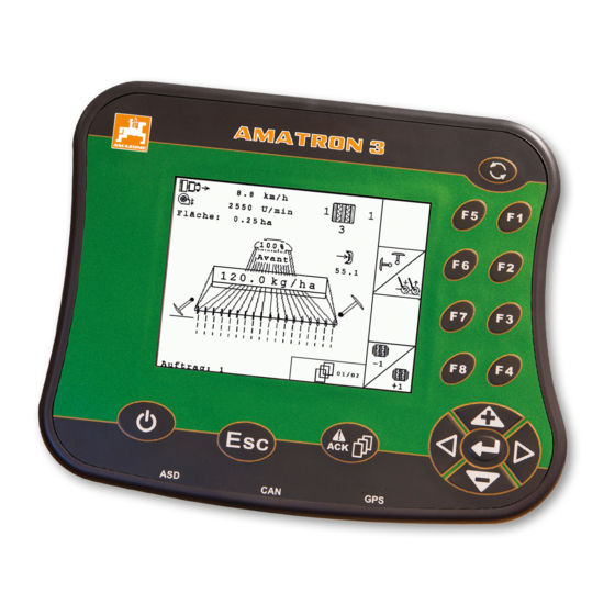
Терминал управления AmaTron 3

Универсальное применение
Управление всеми важными функциями на Avant может осуществляться через терминал управления AmaTron 3. Сюда относятся рабочие функции, а также функции настройки машины, например, калибровка.
Управление всеми важными функциями на Avant может осуществляться через терминал управления AmaTron 3. Сюда относятся рабочие функции, а также функции настройки машины, например, калибровка.
Сервопривод дозирования на Avant позволяет легко проводить калибровку и индивидуальные изменения нормы высева. Электрогидравлическое управление посредством AmaTron 3 позволяет контролировать режим работы Avant и осуществлять настройку машины.
Терминал управления дополнительно контролирует и регулирует ритмы технологической колеи. Сюда относится также возможность нахождения различных препятствий для маркёров. С помощью нового менеджера задач Task Controller возможна подготовка заданий за офисным компьютером и передача их через USB-накопитель на терминал с последующей обработкой. Посредством AmaTron 3 и Avant можно дифференцированно обрабатывать площади с помощью карт в формате Shape. Импульсы скорости поступают от радара.
Reading the instruction
Manual and following it should seem to be in-
convenient and superfluous as it is not
enough to hear from others and to realize that a
machine is good, to buy it and to believe that now
everything should work by itself. The person in
question would not only harm himself but also
make the mistake of blaming the machine for pos-
sible failures instead of himself. In order to ensure
success one should enter the mind of a thing,
make himself familiar with every part of the ma-
chine and get acquainted with how it’s handled.
Only in this way could you be satisfied both with
the machine and with yourself. This goal is the
purpose of this instruction manual.
Leipzig-Plagwitz 1872.
2
AMATRON 3 BAG0094.6 02.15