-
Contents
-
Table of Contents
-
Troubleshooting
-
Bookmarks
Quick Links
PanelView
Standard Operator
Terminals
PV300 Micro, PV300, PV550,
PV600, PV900, PV1000, PV1400
User Manual
Related Manuals for Allen-Bradley PV300 Micro
Summary of Contents for Allen-Bradley PV300 Micro
-
Page 1
PanelView Standard Operator Terminals PV300 Micro, PV300, PV550, PV600, PV900, PV1000, PV1400 User Manual… -
Page 2
Identifies information that is critical for successful IMPORTANT application and understanding of the product. Allen-Bradley, MicroLogix, ControlLogix, FlexLogix, CompactLogix, SLC, PLC, RSLogix, RSLinx, PanelView, PanelBuilder32 are trademarks of Rockwell Automation DeviceNet is a trademark of The Open DeviceNet Vendors Association Modbus is a trademark of Modicon, Inc. -
Page 3: Table Of Contents
Table of Contents Preface Objectives……..P-1 Contents of Manual .
-
Page 4
Alarms ……..5-18 Installing the PV300 Micro… -
Page 5
Table of Contents Installing the PV300 Terminal Chapter 7 Chapter Objectives ……7-1 Hazardous Locations . -
Page 6
Table of Contents Installing the PV1400 Terminal Chapter 11 Chapter Objectives ……11-1 Enclosures . -
Page 7: Objectives
Tells how to copy applications to and from a memory card. Running Applications Describes objects common to most applications. Installing the PV300 Micro Describes enclosure or panel mounting of the Terminal PanelView 300 Micro terminal. Installing the PV300 Terminal Describes enclosure or panel mounting of the PanelView 300 terminal.
-
Page 8: Intended Audience
Preface Intended Audience No special knowledge is required to understand this manual or operate the PanelView terminals. Before running an application, you must know the functions of all screens and screen objects. This information is available from the application designer. Equipment installers must be familiar with standard panel installation techniques.
-
Page 9: Technical Support
Preface Technical Support If you have questions about the PanelView terminals or the PanelBuilder32 software, please refer to the online manuals or online help provided with the PanelBuilder32 installation CD. These publications are also available from the Automation Bookstore or Manuals Online at the www.ab.com website.
-
Page 10: What’s New
Preface What’s New Ethernet communications is now supported on the following PanelView terminals. • PanelView 550 • PanelView 600 • PanelView 900 (not supported on the monochrome versions) • PanelView 1000 • PanelView 1400 All of these terminals are available with an EtherNet/IP connector and RS-232 port for file transfers and/or printing.
-
Page 11: Chapter 1 Chapter Objectives
• AC or DC power (L1 at the end of a catalog number indicates a DC terminal, for example, 2711-B5A1L1, or -T9C1L1). • Stainless steel bezel available on PanelView 550 keypad or keypad & touch terminals. Contact your Allen-Bradley representative for availability. Publication 2711-UM014B-EN-P…
-
Page 12
PanelView 300 Micro Monochrome Terminals The PanelView 300 Micro is available only with 24V dc input power and does not have a printer port. The PV300 Micro contains a single RS-232 communication port which supports either DF1 or DH485 communication protocols as specified in the table below. -
Page 13
Terminal Overview PanelView 550 Monochrome Terminals The Touch Screen version of the PanelView 550 terminal is available only with 24V dc power. The L1 in the catalog number indicates DC power. Communication Port Catalog Operator Printer Port DH-485 RS-232 DeviceNet ControlNet RS-232 Ethernet… -
Page 14
Terminal Overview PanelView 600 Color Terminals Communication Port Catalog Operator Printer Port DH-485 RS-232 DeviceNet ControlNet RS-232 Ethernet Input RS-232 Number (DH-485) (DF1) 2711-B6C1 2711-B6C2 2711-B6C3 2711-B6C5 2711-B6C8 Touch Screen and Keypad 2711-B6C9 2711-B6C10 2711-B6C15 2711-B6C16 2711-B6C20 2711-K6C1 2711-K6C2 2711-K6C3 2711-K6C5 2711-K6C8 Keypad… -
Page 15
Terminal Overview PanelView 900 Monochrome Terminals These terminals are no longer available for purchase. Communication Port Catalog Operator Printer Port DH-485 RS-232 DeviceNet ControlNet RS-232 Input RS-232 Number (DH-485) (DF1) 2711-T9A1 2711-T9A2 2711-T9A3 2711-T9A5 Touch 2711-T9A8 Screen 2711-T9A9 2711-T9A10 2711-T9A15 2711-T9A16 2711-K9A1 2711-K9A2… -
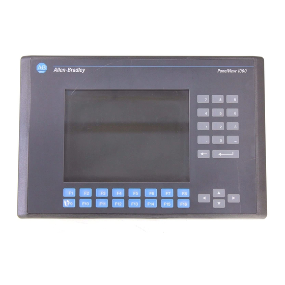
Page 16
Terminal Overview PanelView 1000 Color Terminals Communication Port Catalog Operator Printer Port DH-485 RS-232 DeviceNet ControlNet RS-232 Ethernet Input RS-232 Number (DH-485) (DF1) 2711-T10C1 2711-T10C3 2711-T10C8 2711-T10C9 Touch Screen 2711-T10C10 2711-T10C15 2711-T10C16 2711-T10C20 2711-K10C1 2711-K10C3 2711-K10C8 2711-K10C9 Keypad 2711-K10C10 2711-K10C15 2711-K10C16 2711-K10C20 Add L1 to the end of the catalog number for 24V dc power. -
Page 17
Terminal Overview PanelView 1400 Color Terminals Communication Port Catalog Operator Printer Port DH-485 RS-232 DeviceNet ControlNet RS-232 Ethernet Input RS-232 Number (DH-485) (DF1) 2711-T14C1 2711-T14C3 2711-T14C8 2711-T14C9 Touch Screen 2711-T14C10 2711-T14C15 2711-T14C16 2711-T14C20 2711-K14C1 2711-K14C3 2711-K14C8 2711-K14C9 Keypad 2711-K14C10 2711-K14C15 2711-K14C16 2711-K14C20 Publication 2711-UM014B-EN-P… -
Page 18: Panelview 300 Micro Features
Terminal Overview PanelView 300 Micro This section defines features of the PanelView 300 Micro keypad terminal. Features PanelView 300 Micro Features (Front) Feature Description Function Keys Use the function keys to initiate functions on the terminal (F1 — F4) display. Cursor Keys Use the cursor keys (left, right, up, down) as programmed function keys in addition to the F1 — F4 function keys or to…
-
Page 19
Terminal Overview PanelView 300 Micro Features (Back) Feature Description Power Connection Terminals Connects to a 24V dc (11-30 V dc) external power source. DF1 or DH-485 (RS232) Connects to an SLC, PLC, or MicroLogix controller using an RS-232 Communication Port connection. -
Page 20: Panelview 300 Features
1-10 Terminal Overview PanelView 300 Features This section defines features of the PanelView 300 keypad terminal. PanelView 300 Features (Front) Feature Description Function Keys Use the function keys to initiate functions on the terminal (F1 — F8) display. These keys may have custom legends. Cursor Keys Use the up or down cursor keys to move the cursor up or down in a list or to increment/decrement values.
-
Page 21
Terminal Overview 1-11 PanelView 300 Features (Back) DeviceNet with additional RS-232 Port 10 12 DH-485 without RS-232 Port RS-232 (DH-485 or DF1) without additional RS-232 Port 7, 8, 9, 10, 11, 12 9 or 11 Feature Description Nameplate Label Provides product information. Sealing Gasket Seals the front of the terminal to an enclosure or panel. -
Page 22: Panelview 550 Features
1-12 Terminal Overview PanelView 550 Features This section defines features of the PanelView 550 terminals. PanelView 550 Features (Front) Keypad Terminal Keypad & Touch Screen Terminal Cell 16 Cell 1 Cell 113 Cell 128 Touch Screen Terminal Cell 1 Cell 16 Cell 113 Cell 128 Publication 2711-UM014B-EN-P…
-
Page 23
Terminal Overview 1-13 Feature Description Function Keys On keypad terminals, use the function keys to initiate (F1 — F10) functions on the terminal display. These keys may have custom legends. On keypad & touch screen terminals, you can initiate functions using the function keys and/or touch screen objects. -
Page 24
1-14 Terminal Overview PanelView 550 Keypad or Keypad & Touch Screen Terminals (Back) DH-485 without additional RS-232 Port AC connector shown, DC connector looks different DH-485 with additional RS-232 Port Backlight lamp behind access cover RS-232 (DH-485) Remote I/O, DF1, DH+, DeviceNet, ControlNet, Ethernet, without additional RS-232 Port with additional RS-232 Port 13, 14, 15, 16, 17, or 18… -
Page 25
Terminal Overview 1-15 Feature Description Power Connection Terminals Connects to external power source. Nameplate Label Provides product information. Sealing Gasket Seals the front of the terminal to an enclosure or panel. COMM LED (Green) Indicates when communications is occurring. FAULT LED (Red) Indicates firmware or hardware faults. -
Page 26
1-16 Terminal Overview PanelView 550 Touch Screen Terminal Features (Back) DH-485 without additional RS-232 Port DH-485 with RS-232 Port Backlight lamp behind access cover RS-232 (DH-485) without additional RS-232 Port Remote I/O, DF1, DH+, DeviceNet, ControlNet, Ethernet, with RS-232 Port RS-232 (DH-485) with additional RS-232 Port 13, 14, 15, 16, 17, or 18 Publication 2711-UM014B-EN-P… -
Page 27
Terminal Overview 1-17 Feature Description Power Connection Terminals Connects to external DC power source. Sealing Gasket Seals the front of the terminal to an enclosure or panel. FAULT LED (Red) Indicates firmware or hardware faults. COMM LED (Green) Indicates when communications is occurring. Nameplate Label Provides product information. -
Page 28: Panelview 600 Features
1-18 Terminal Overview PanelView 600 Features This section defines features of the PanelView 600 terminals. PanelView 600 Features (Front) Keypad Terminal Keypad & Touch Screen Terminal Cell 16 Cell 1 Cell 128 Cell 113 Touch Screen Terminal Cell 1 Cell 16 Cell 128 Cell 113 Publication 2711-UM014B-EN-P…
-
Page 29
Terminal Overview 1-19 Feature Description Function Keys (F1 — F10) Use the function keys on keypad terminals to initiate functions on the terminal display. These keys may have custom legends. On the keypad & touch screen terminals, you can initiate functions using the function keys and/or touch screen objects. -
Page 30
1-20 Terminal Overview PanelView 600 Keypad or Keypad & Touch Screen Terminal (Back) Remote I/O, DF1, DH+, DeviceNet, ControlNet, or Ethernet with additional RS-232 Port 10, 11, 12, 13, 14, or 15 DH-485 without additional RS-232 Port 7, 8, 9, 10 11, 12, 13, 14, 15, 16 DH-485 with additional RS-232 Port RS-232 (DH-485) -
Page 31
Terminal Overview 1-21 Feature Description Power Connection Terminals Connects to external power source. Nameplate Label Provides product information. Memory Card Slot Accepts a memory card which stores applications. Sealing Gasket Seals the front of the terminal to an enclosure or panel. FAULT LED (Red) Indicates firmware or hardware faults. -
Page 32
1-22 Terminal Overview PanelView 600 Touch-Screen Terminal Features (Back) Remote I/O, DF1, DH+, DeviceNet, ControlNet, or Ethernet with additional RS-232 Port 11, 12, 13, 14, 15, or 16 DH-485 without additional RS-232 Port 8, 9, 10, 11 12, 13, 14, 15, 16, 17 DH-485 with additonal RS-232 Port RS-232 (DH-485) RS-232 (DH-485) with additional RS-232 Port… -
Page 33
Terminal Overview 1-23 Feature Description Power Connection Terminals Connects to external power source. Nameplate Label Provides product information. Fault LED (Red) Indicates firmware or hardware faults. COMM LED (Green) Indicates when communications is occurring. Sealing Gasket Seals the front of the terminal to an enclosure or panel. Reset Button Resets the terminal. -
Page 34: Panelview 900/1000 Features
1-24 Terminal Overview PanelView 900/1000 This section defines features of the PanelView 900 and 1000 terminals. Features PanelView 900/1000 Terminal Features (Front) Keypad Terminal Touch Screen Terminal Cell 1 Cell 24 Cell 361 Cell 384 Publication 2711-UM014B-EN-P…
-
Page 35
Terminal Overview 1-25 Feature Description Function Keys (F1 — F16) Use the function keys on keypad terminals to initiate functions on the terminal display. These keys may have custom legends. Cursor Keys Use the cursor keys to move the cursor in displayed lists, to select a numeric entry object or to enter configuration mode. -
Page 36
1-26 Terminal Overview PanelView 900/1000 Terminal Features (Back) Remote I/O, DF1, DH+, DeviceNet, Ethernet, or ControlNet with additional RS-232 Port Back View Touch Screen Terminal 11, 12, 13, 14, 15, or 16 DH-485 Version without additional RS-232 Port 8, 9, 10 11, 12, 13, 14, 15, 16, 17 DH-485 with additional RS-232 Port Back View… -
Page 37
Terminal Overview 1-27 Feature Description Power Connection Terminals Connects to external power source. Nameplate Label Provides product information. Reset Button Resets the terminal. Sealing Gasket Seals the front of the terminal to an enclosure or panel. Memory Card Slot Accepts a memory card which stores applications. FAULT LED (Red) Indicates firmware or hardware faults. -
Page 38: Panelview 1400 Features
1-28 Terminal Overview PanelView 1400 Features This section defines features of the PanelView 1400 terminals. PanelView 1400 Terminal Features (Front) Keypad Terminal Touch Screen Terminal Cell 1 Cell 24 Cell 384 Cell 361 Publication 2711-UM014B-EN-P…
-
Page 39
Terminal Overview 1-29 Feature Description Function Keys (F1 — F21) Use the function keys on keypad terminals to initiate functions on the terminal display. These keys may have custom legends. Cursor Keys Use the cursor keys to move the cursor in displayed lists, to select a numeric entry object, or to enter configuration mode. -
Page 40
1-30 Terminal Overview PanelView 1400 Terminal Features (Back and Sides) Remote I/O, DF1, DH+, DeviceNet, ControlNet, or Ethernet with additional RS-232 Port 7, 8, 9 10, 11, 12 13, 14, 15, 16 10, 11, 12, 13, 14, or 15 DH-485 with additional RS-232 Port Left Side RS-232 (DH-485) with additional RS-232 Port Right Side… -
Page 41
Terminal Overview 1-31 Feature Description Brightness Control Adjusts the brightness of the color display. Contrast Control Adjusts the contrast of the color display. Nameplate Label Provides product information. FAULT LED (Red) Indicates firmware or hardware faults. COMM LED (Green) Indicates when communications is occurring. Power Connection Terminals Connects to external power source. -
Page 42: Applications
1-32 Terminal Overview Applications PanelView terminals operate with custom designed applications. The first time you power on the terminal, (no application file loaded), the terminal displays the Configuration Mode menu. Chapter 3 describes the terminal functions you can configure from this menu. Note: Remote I/O terminals provide an out-of-box application for setting Remote I/O communication parameters.
-
Page 43
Terminal Overview 1-33 Touch Screen Operation Applications for touch screen terminals are controlled by touching screen objects. Keypad Operation Applications for keypad terminals are controlled by pressing function keys that correspond to screen objects. Data is entered manually using the numeric entry keys. A function key legend kit is available for each terminal (except the 300 Micro) to create custom labels for the function keys. -
Page 44: Configuration Mode Menu
1-34 Terminal Overview Configuration Mode Menu You can configure terminal functions from the Configuration Mode menu including: • select a language • upload/download applications with a memory card • set or display serial communication parameters • select preset values • obtain terminal and application information •…
-
Page 45: Alarm List
Terminal Overview 1-35 Alarm List PanelView terminals support an Alarm List queue to store information on triggered alarms. The Alarm List stores a maximum of 100 alarms or as many as the terminal can hold in nonvolatile RAM. The number of alarms stored in the list is configured using the PanelBuilder32 software.
-
Page 46: Accessories
2711-NMCD Secures memory card in 550 touch screen terminal and prevents electrostatic discharge. 2711-NMCE Secures memory card in PanelView 300 keypad and 600 touch screen terminals and prevents electrostatic discharge. Contact Allen-Bradley for availability. Not available for purchase. Publication 2711-UM014B-EN-P…
-
Page 47
Terminal Overview 1-37 Antiglare Overlay Self-adhesive filters minimize the reflection of terminal displays. Catalog No. 300M 300 1000 1400 2711-NV4 (Keypad) 2711-NV4T (Touch Screen Terminals) 2711-NV3K (Keypad) 2711-NV3T (Touch Screen Terminals) 2711-NV5 (Keypad) 2711-NV7K (Keypad Terminals) 2711-NV7T (Touch Screen Terminals) 2711-NV6K (Keypad Terminals) 2711-NV6T (Touch Screen Terminals) 2711-NV8 (Keypad Terminals) -
Page 48
1-38 Terminal Overview PanelView File Transfer Utility Catalog No. Description 2711-ND7 Transfers .PVA files between a PanelView terminal and a computer running Windows. Power Supply and Link Couplers The following items are available for all PanelView terminals. Catalog No. Description 1747-NP1 Wallmount Power supply provides power for DH-485 communications when an SLC or network is not connected. -
Page 49
(except PV300 Micro). 2711-NC22 15 meter (49 foot) cable connects an RS-232 terminal to a MicroLogix controller (except PV300 Micro). 2706-NC13 3 meter (10 ft) cable connects an RS-232 terminal to an SLC 5/03 controller or the RS-232 port of a computer or printer. -
Page 50: Replacement Parts
1-40 Terminal Overview Replacement Parts Backlight Lamps Catalog No. 1000 Description 2711-NL1 Halogen backlight lamp for all PV550 terminals. Provides backlighting for LCD display. 2711-NL2 Backlight for PV900 color terminal. 2711-NL3 Backlight for PV600 color terminal. 2711-NL4 Backlight for PV1000 color terminal. Real Time Clock Modules Catalog No.
-
Page 51: Chapter 2 Chapter Objectives
Chapter Applying Power and Resetting Terminal Chapter Objectives This chapter provides information on: • wiring and safety guidelines • connecting AC or DC power • resetting the terminal • power-up sequence Wiring and Safety Use publication NFPA 70E, Electrical Safety Requirements for Employee Workplaces when wiring the PanelView terminals.
-
Page 52: Connecting Ac Power
Applying Power and Resetting Terminal Connecting AC Power Below are AC electrical ratings for the PanelView terminals. The PV550/PV600 touch screen only terminal is available only with DC power, not AC power. Terminal Type Supply Voltage Power Consumption PV550 85 to 264V ac, 47 to 63 Hz 45 VA maximum PV600 85 to 264V ac, 43 to 63 Hz…
-
Page 53
Applying Power and Resetting Terminal PanelView 550 Terminal 120/240V ac, 3 Wire, 120/240V ac, 3 Wire, European Harmonized Color Code U.S. Color Code L1 L2N GND L1 L2N Black (Line) White (Neutral) Blue (Neutral) Green/Yellow Brown (Line) Green (Earth Ground) (Protective Earth) To Power Source To Power Source… -
Page 54: Connecting Dc Power
Electronic circuitry and an internal fuse protect the terminals from reverse polarity and over-voltage conditions. Supply Voltage Terminal Type Power Consumption (24V dc nominal) PV300 Micro 11 to 30V dc 2.5 Watts max. (0.105A @ 24V PV300 18 to 32V dc 10 Watts max. (0.42A @ 24V…
-
Page 55
Applying Power and Resetting Terminal DC Power Connections Connect the power source to the terminal at the 3-screw terminal block (PV300 Micro removable, all others fixed). Explosion Hazard DANGER • Substitution of components may impair suitability for Class I, Division 2. -
Page 56
Applying Power and Resetting Terminal To connect power to the DC versions of the PanelView: 1. Secure the DC power wires to the terminal block screws. PanelView 300 Terminal PanelView 900/1000 Terminal PanelView 550/600 Terminal Power Terminal Power Terminal Block (fixed) Block (fixed) Note: In the PanelView 300, the Earth Ground Earth Ground… -
Page 57: Resetting The Terminal
Resetting the Terminal Resetting the terminal re-initializes the PanelView terminal (same as cycling power). To reset the PV300, PV300 Micro, PV550 (keypad, keypad & touch) or the PV600 (keypad, keypad & touch): • Simultaneously press the Left arrow , Right arrow , and Enter ↵…
-
Page 58: Power-Up Sequence
• If an application is not loaded, the Configuration Mode menu appears. Function keys do not appear on touch screen terminals. PV900 Keypad Terminal Note: On PV550/600 terminals, the Reset Video is F9. On PV300 and PV300 Micro terminals, the Reset Video is F2. Publication 2711-UM014B-EN-P…
-
Page 59
Applying Power and Resetting Terminal For Remote I/O Terminals An out-of-box application screen opens allowing you to set Remote I/O parameters for the terminal. This screen is only available for initial setup. Once an application is downloaded, the Remote I/O setup screen is erased. -
Page 60
2-10 Applying Power and Resetting Terminal Press this function key on: To set this RIO Description Options Parameter: 550/600 900/1000/1400 ↵ Rack # Rack address of terminal on RIO network. 0 to 76 On PV550/600: Press ↵ to open the scratchpad. -
Page 61: Chapter 3 Chapter Objectives
Chapter Configuring the Terminal Chapter Objectives This chapter shows how to use the Configuration Mode menu to configure terminal settings and perform operations including how to: • access the Configuration Mode menu • select a language • use a memory card •…
-
Page 62: Accessing The Configuration Mode Menu
Function keys do not List appear on touch screen terminals. PV300/PV300 Micro Keypad Terminal On PV550/600 terminals, the Reset Video button is F9. On PanelView 300, 300 Micro terminals, the Reset Video button is F2. Operations List Select an operation using the Up or Down arrow keys.
-
Page 63: Selecting A Language
Selecting a Language Press the Language button, [F8] key, from the Configuration Mode menu to display the Language Selection screen. Note: On PV300 and PV300 Micro terminals, scroll down on the main configuration menu to select a language. Choisir Français Deutsches Meün auswãhlen…
-
Page 64
Configuring the Terminal Using a Memory Card Select Memory Card from the Configuration Mode menu to transfer applications between a memory card and the terminal. The PanelView 300 Micro does not support a memory card. Chapter 4 describes the transfer procedure. Valid Card Inserted Memory APPLICATIONS ON CARD… -
Page 65
Configuring the Terminal Configuring Select Communication Setup from the Configuration Mode menu to display or change the communication settings for your PanelView Communications terminal. The screen that appears depends on the communication protocol of the terminal. DH-485 Communications The DH-485 screen lets you modify or display DH-485 settings for either a DH-485 or RS-232 PanelView terminal. -
Page 66
Configuring the Terminal Comm LED • solid fill — normal operating state • blinking — no communications established • no fill — hardware failure Fault LED • no fill — normal operating state • blinking — hardware is functioning but an application is not loaded or the current application is corrupted. -
Page 67
Configuring the Terminal DH+ Communications The DH+ screen lets you display or modify communication settings for the DH+ version of the PanelView terminals. Settings downloaded with a DH+ application take IMPORTANT priority over terminal settings and take effect immediately after the download. Node: Baud: 57.6 K… -
Page 68
Displays the starting module group of the terminal: 0,1 2,3 4,5 6,7 Pass-Through Enabled (read only) Enables/disables Pass-Through which allows you to transfer applications between a computer on the Allen-Bradley DH+ network and a terminal on the Remote I/O link. A PLC-5 controller passes data between the two networks. -
Page 69
Configuring the Terminal ControlNet Communications The ControlNet screen lets you display communications settings for a ControlNet terminal. You are only allowed to change the Node Address and Interscan Delay settings. Settings downloaded with a ControlNet application IMPORTANT take priority over terminal settings and take effect immediately after the download. -
Page 70
Value Value Status Indicates Priority Terminal failure. Contact Allen-Bradley for technical support. 1 (Highest) Self test being performed. Wait for end of test. Incorrect node configuration. Check for duplicate nodes. Incorrect network configuration (such as overflow/underflow if signaled by host, out-of-step). Check for a node greater than UMAX. -
Page 71
Configuring the Terminal 3-11 DeviceNet Communications The DeviceNet screen lets you display or modify communication settings for a DeviceNet terminal. Settings downloaded with a DeviceNet application IMPORTANT take priority over terminal settings and take effect immediately after the download. DeviceNet New Node Address F2: Input Size: Output Size:… -
Page 72
3-12 Configuring the Terminal Active Baud (read only) Displays the current baud rate of the PanelView terminal. The new baud is displayed after a reset. If the baud rate was set to AutoBaud, active baud displays the rate set by the terminal. If the baud rate was set to PGM, the active baud displays the most recent baud stored on the communications card. -
Page 73
Configuring the Terminal 3-13 DF1 Communications The DF1 screen lets you display or modify DF1/full duplex communication settings for a DF1 PanelView terminal. Settings downloaded with a DF1 application have IMPORTANT priority over terminal settings and take effect immediately after the download. Typical DF1 Setup Screens DF1 — Full Duplex Communication… -
Page 74
3-14 Configuring the Terminal Node Specifies the node number (0 — 254 decimal) for DF1 network communications. For point-to-point communications with an SLC, PLC, MicroLogix or a 1761-NET DNI module, the default node number of 64 is used. When you press F4, the numeric entry scratchpad opens. Enter a node number and press the Enter ↵… -
Page 75
Configuring the Terminal 3-15 EtherNet/IP Communications The EtherNet/IP screen lets you display or modify some of the EtherNet/IP communication settings for an Ethernet PanelView terminal. Additional parameters (Gateway Address, DNS Server and Domain Name, and Timeout values) are set in the Communications Setup dialog of the PanelBuilder32 software and downloaded with the application. -
Page 76
3-16 Configuring the Terminal IP Address A unique address identifying the PanelView node on the EtherNet/IP network. The IP address is formatted as four sets of decimal numbers with periods between them (10.0.0.1). The range of values for the first set of decimal numbers is 1 — 255, unless all fields are set to 0.0.0.0. -
Page 77
Configuring the Terminal 3-17 Configuring Presets Select Preset Operations from the Configuration Mode menu to set the values of control objects after a reset or power cycle. You can set presets to: • values provided by the PanelView application or •… -
Page 78: Viewing Terminal Information
3-18 Configuring the Terminal Viewing Terminal Select Terminal Info from the Configuration Mode menu to display information about your terminal. This information may be needed Information when calling for technical support. TERMINAL INFO Boot: ############ Firmware: ############ Hardware: ####################################### Filename: ############ Fontfile: ############…
-
Page 79: Adjusting Screen Parameters
Configuring the Terminal 3-19 Adjusting Screen Select Screen Setup from the Configuration Mode menu to adjust settings of the terminal display. Changes take effect immediately. Parameters PanelView 300 Micro Screen Setup The PanelView 300 Micro backlight is always on and intensity is not adjustable.
-
Page 80
3-20 Configuring the Terminal PanelView 300 Screen Setup SCREEN SETUP SCREEN SAVER F1 Contrast F1 Mode F2 Mode Normal F2 Timeout 10 min. F3 Reset Video F7 MORE F8 EXIT F7 MORE F8 EXIT Certain settings may make viewing the screen IMPORTANT difficult. -
Page 81
Configuring the Terminal 3-21 PanelView 550 Screen Setup SCREEN SETUP Backlight Contrast Video Mode Reverse Backlight Timeout 10 min. EXIT Reset Video Certain settings may make viewing the screen IMPORTANT difficult. Do not exit this screen until viewing adjustments are acceptable. Backlight Turns the backlight On, Off or to Timed mode. -
Page 82
3-22 Configuring the Terminal PanelView 600/900/1000 Color — Screen Setup SCREEN SETUP SCREEN SETUP Normal Screen SCREEN SAVER Saver Intensity Contrast Timed Reset Video Timeout Reset 10 min. SCREEN SAVER Video Timeout Intensity Intensity 10 min. EXIT EXIT color palette adjusts with contrast PV600 color touch-screen only PV600/900/1000 color… -
Page 83
Configuring the Terminal 3-23 PanelView 900 Monochrome — Screen Setup SCREEN SETUP SCREEN SAVER SCREEN CONDITIONER Mode Normal Intensity Mode Timed Disabled Video Mode Timeout Hour Minute Normal 10 min. ## : Intensity Reset Video EXIT Certain settings may make viewing the screen IMPORTANT difficult. -
Page 84
3-24 Configuring the Terminal Screen Conditioner Mode Enables or disables the screen conditioner. This parameter sets a daily schedule for conditioning the display of a PV900 monochrome terminal to prevent image burn-in. The conditioning process takes approximately 30 minutes and will not start until the terminal is inactive and in screen saver mode. -
Page 85
Configuring the Terminal 3-25 PanelView 1000 Grayscale -Screen Setup SCREEN SETUP Screen Video Saver Mode Reset Normal Video SCREEN SAVER Timeout Intensity 10 min. EXIT Certain settings may make viewing the screen IMPORTANT difficult. Do not exit this screen until viewing adjustments are acceptable. -
Page 86
3-26 Configuring the Terminal PanelView 1400 Color Setup SCREEN SETUP SCREEN DEGAUSS Normal SAVER Intensity Auto Mode Enabled Timeout Hour Minute Reset 5 min. Touch Screen only Video Intensity Manual ALIGN EXIT Degauss TOUCH GRID Certain settings may make viewing the screen IMPORTANT difficult. -
Page 87
Configuring the Terminal 3-27 Normal Intensity Adjusts the intensity of the display with each key press: 25, 50, 75, 100. The new setting takes effect immediately. Reset Video Resets the display to normal video (default settings). On keypad terminals, the reset video [F15] key is also active on the Configuration Mode menu. -
Page 88: Setting The Time And Date
MMM/DD/YYYY Setting the Time Use screen buttons (touch screens) or function keys to set the time. On PV300, On PV550/PV600 On PV900/1000/1400 PV300 Micro: Press: Press: Use the left and right Hours button [F6] Hour button [F9] key Set current hour…
-
Page 89: Setting Up The Printer
Configuring the Terminal 3-29 Setting up the Printer Select Printer Setup from the Configuration Mode menu to set parameters for those terminals equipped with an RS-232 printer port. Any printer that supports the IBM enhanced character set can be connected to the RS-232 printer port. PRINTER SETUP Handshaking Communication Parameters…
-
Page 90
3-30 Configuring the Terminal Top of Form Notifies the PanelView terminal the printer is at the top of a page. Manually adjust the printer to the top of the page before pressing the Top of Form button. The printer also uses the Perforation Skip Value (if defined in the Printer Setup of the PanelBuilder32 software) when the Top of Form button is pressed. -
Page 91: Using A Memory Card
Chapter Using a Memory Card Chapter Objectives This chapter describes: • supported memory cards • using the memory card retainer • loading application from a memory card • loading application on a memory card • storing font files on a memory card •…
-
Page 92: Using The Memory Card Retainer
Using a Memory Card Using the Memory Card A Memory Card Retainer (Catalog No. 2711-NMCC, -NMCD, -NMCE) is shipped with all PanelView terminals, except the PV300 Retainer Micro and the PV1400. It is required for: • UL508 installations • vibration/mechanical shock environments •…
-
Page 93
Using a Memory Card The Memory Card Retainer protects against: • electrical shock from loose high voltage wires in an electrical enclosure per UL508 When permanently installing a memory card in ATTENTION an electrical enclosure, the memory card retainer must be used to avoid accidental contact of high voltage leads to metal surfaces on the card. -
Page 94: Loading Application From A Memory Card
Using a Memory Card Loading Application The procedure below shows how to load an application on a memory card into the PanelView terminal. from a Memory Card Explosion Hazard — Do not install or remove memory ATTENTION card unless power has been switched off or the area is known to be non-hazardous.
-
Page 95
Using a Memory Card 5. Press Restore From Card, [F2] on keypad terminals, to begin the transfer. Because this operation overwrites the current application in the terminal, you are prompted to abort or continue. Proceed with download? F1 — Abort F2 — Continue The terminal displays the status of the transfer. -
Page 96: Loading Application On A Memory Card
Using a Memory Card Loading Application The steps below show how to load an application in the terminal onto a memory card. on a Memory Card Explosion Hazard — Do not install or remove memory ATTENTION card unless power has been switched off or the area is known to be non-hazardous.
-
Page 97
Using a Memory Card 4. If necessary, press Erase/Format Card, [F4] key on keypad terminals, to format or erase a 2711-NM11, -12, -13, -14, -15 memory card. Do not perform this operation on a IMPORTANT 2711-NM2xx ATA card (where xx is size in megabytes). -
Page 98: Storing Font Files On A Memory Card
Using a Memory Card Storing Font Files Memory cards also store font files for languages used by PanelView applications. The font file contains the character set for the language. on a Memory Card The memory card containing the font file must be inserted in the PanelView terminal while the application is running.
-
Page 99: Chapter 5 Chapter Objectives
Chapter Running Applications Chapter Objectives This chapter describes operating procedures common to most applications: screen security alarms push button operation printing control lists time or date numeric entry controls message displays ASCII entry controls numeric data displays screen selectors bar graphs list indicators analog gauges multistate indicators…
-
Page 100: Screen Security
Running Applications Screen Security Access to some application screens (including the terminal configuration screens) may be restricted. Secured screens require you to enter a password before the screen is displayed. It is the responsibility of the application designer to provide operators with required passwords.
-
Page 101: Control Lists
Running Applications Control Lists Control lists perform functions similar to push buttons. They can modify either individual bits or values at a controller address. Cursor indicates selected item Active selection is highlighted Vertical bar indicates active control list Active List Item Active item is highlighted.
-
Page 102
Running Applications Cursor Indicates the selected item. Move the cursor up or down the control list using the Up and Down arrow keys. Cursor operation is configured by the application designer. If the cursor is at the first or last item in a control list pressing the Up arrow (when at the top) or the Down arrow (when at the bottom) will either: •… -
Page 103
Running Applications Cursor — Piloted Control Lists On a piloted control list, some items are under controller operation only. In addition, some items may be designated as inactive. You cannot select controller items or inactive items. In both cases, the cursor is hollow when you select the item. -
Page 104
Running Applications Two types of controls allow a numeric value at a controller address: Cursor Point and Keypad Enable button. Press F1 to Enter New Speed Current Speed = 100 RPM Cursor Point Motor 1 Active Motor 2 Cursor Point Numeric Entry Cursor Point Cursor points appear as a box. -
Page 105
Running Applications To enter a cursor point: 1. Select the cursor point by: • touching the object (touch screen terminal only) • pressing the associated function key • press the Left or Right arrows until the cursor point shows a vertical bar 2. -
Page 106
Running Applications PanelView 300, 300 Micro Thumbwheel Scratchpad The thumbwheel scratch pad allows an operator to enter values on terminals without a numeric keypad or touch screen by cycling through the available characters one position at a time. Use the Up and Down cursors to cycle through the available characters. -
Page 107: Ascii Entry Controls
Running Applications ASCII Entry Controls ASCII entry controls allow you to send an alphanumeric string (up to 128 characters) to a controller. Like numeric entry controls, the ASCII entry control can appear on a screen as a keypad enable button or a cursor point.
-
Page 108
5-10 Running Applications ASCII Scratchpad — 300 Micro/300 Terminals The thumbwheel scratch pad allows an operator to enter values on terminals without a numeric keypad or touch screen by cycling through the available characters one position at a time. This is the character sequence: <space>… -
Page 109
Running Applications 5-11 ASCII Scratchpad — 550/600 Touch Screen Terminals Cursor Character Keyboard Display Area Cursor Control Keys Controls To select characters from the Character Keyboard, press the cursor control keys to move the cursor over a character and then press the SEL key. -
Page 110
5-12 Running Applications ASCII Scratchpad — 900/1000/1400 Touch Screen Terminals Display Area Character Keyboard Controls Select characters by touching the Character Keyboard on the screen. The character is entered in the Display Area. This area scrolls so you can enter a string that is longer than the Display Area. All characters are sent to the controller even if not visible. -
Page 111
Running Applications 5-13 ASCII Scratchpads in Other Languages The ASCII Scratchpad is available with character keyboards in: • French • German • Italian • Spanish If the PanelView terminal is configured for operation in one these languages, the ASCII scratchpad will display the appropriate Character Keyboard. -
Page 112: Screen Selectors
5-14 Running Applications Screen Selectors The 2 types of screen selector controls are Screen List Selectors and Screen buttons. Screen List Selector Screen Controls Tank Monitor Screen Goto Screen Button Pump Status Valve Status Previous Screen Tank Control Vertical Bar Return Screen Button indicates active list Goto and Return screen buttons can have a variety of appearances…
-
Page 113
Running Applications 5-15 Cursor Operation Cursor operation is configured by the application designer. If the cursor is at the first or last item in a screen list, pressing the Up arrow (when at top) or Down arrow (when at bottom) will either: •… -
Page 114: List Indicators
5-16 Running Applications List Indicators List indicators highlight an item from a list depending upon the status of either a bit or value at a controller address. List Indicator Mixer Speed Mixer Medium Current status Mixer High is highlighted An indicator list may have a maximum of 255 entries. The list automatically scrolls to display the status of an item.
-
Page 115: Numeric Data Displays
Running Applications 5-17 Numeric Data Displays Numeric Data Displays may appear with or without supporting text. Flow= 37 Gallons 0 0 0 2 3 9 . 4 5 Depending on the application design, displayed data may have these properties: • zero fill •…
-
Page 116: Printing
5-18 Running Applications Printing Terminals equipped with an RS-232 printer port can print: • triggered messages in a message display • triggered states of a multistate indicator • alarm messages • alarm list Text is printed without formatting options. Print attributes for objects and alarms are defined in the application.
-
Page 117: Chapter 6 Chapter Objectives
• mounting dimensions • clearances • cutout dimensions • installing the PV300 micro terminal in a panel Hazardous Locations This equipment is suitable for use in Class 1, Division 2, Groups A, B, C, D or non-hazardous locations only. The following DANGER statement applies to use in hazardous locations.
-
Page 118: Enclosures
Installing the PV300 Micro Terminal Enclosures Mount the PanelView 300 Micro terminal in a panel or enclosure to protect the internal circuitry. The terminal meets NEMA 12/13, 4X (indoor use), IP54 or IP65 ratings only when properly mounted in a panel or enclosure with the equivalent rating.
-
Page 119: Cutout Dimensions
Installing the PV300 Micro Terminal Cutout Dimensions Use the full size template shipped with the PV300 Micro to mark the cutout dimensions. The figure below shows a reduced scale cutout. A full scale template is also available inside the back cover of this document.
-
Page 120: Installing Terminal In Panel
Installing the PV300 Micro Terminal Installing Terminal in Panel To install the PV300 Micro in a panel: • Disconnect all electrical power from the panel ATTENTION before making cutout. • Make sure area around the panel cutout is clear. • Take precautions so that metal cuttings do not enter any components already installed in panel.
-
Page 121
Installing the PV300 Micro Terminal Self-Locking Nuts (4 used, 6 provided) 7. Alternately tighten the self-locking nuts until the terminal is held firmly against the panel. Tighten the nuts to a torque of 10 inch-pounds. Do not overtighten. Mounting nuts must be tightened to a torque of 10… -
Page 122
Installing the PV300 Micro Terminal Publication 2711-UM014B-EN-P… -
Page 123: Chapter 7 Chapter Objectives
Chapter Installing the PV300 Terminal Chapter Objectives This chapter shows how to install the PanelView 300 terminal and covers: • hazardous locations • enclosures • required tools • mounting dimensions • clearances • cutout dimensions • installing the PV300 terminal in a panel Hazardous Locations See the nameplate label on terminal for hazardous location certifications.
-
Page 124: Enclosures
Installing the PV300 Terminal Enclosures Mount the PV300 terminal in a panel or enclosure to protect the internal circuitry. The terminal meets NEMA Type 12/13 and 4X (indoor use) ratings only when mounted in a panel or enclosure with the equivalent rating. Allow enough space within the enclosure for adequate ventilation.
-
Page 125: Mounting Dimensions
Installing the PV300 Terminal Mounting Dimensions The illustration below shows mounting dimensions for the PV300 keypad terminals. Top View 69mm 82 mm 197 mm (2.73 in) (3.21 in) (7.76 in) 140 mm (5.53 in) Cutout Dimensions Use the full size template shipped with the PV300 terminal to mark the cutout dimensions.
-
Page 126: Clearances
Installing the PV300 Terminal Clearances When installing the PV300 terminal, allow space for mounting, air flow, maintenance, memory card and legend strip installation. Side, Top and Bottom Clearances Leave 64 mm (2.5 in) for Mounting and Air Flow Terminal Cutout Recommended Panel Use full size template Cutout Dimensions…
-
Page 127: Installing The Pv300 In A Panel
Installing the PV300 Terminal Installing the PV300 in a To install the PV300 terminal in a panel: Panel • Disconnect all electrical power from the panel ATTENTION before making the cutout. • Make sure the area around the panel cutout is clear.
-
Page 128
Mounting nuts must be tightened to a torque of ATTENTION 10 inch-pounds to provide a proper seal and to prevent potential damage to the terminal. Allen-Bradley assumes no responsibility for water or chemical damage to the terminal or other equipment within the enclosure because of improper installation. -
Page 129: Chapter 8 Chapter Objectives
Chapter Installing the PV550 Terminal Chapter Objectives This chapter describes how to mount the PV550 terminal in a panel or enclosure including: • hazardous locations • enclosures • required tools • mounting dimensions • clearances • cutout dimensions • installing the PV550 terminal in a panel Hazardous Locations See the nameplate label on terminal for hazardous locations certifications.
-
Page 130: Enclosures
Installing the PV550 Terminal Enclosures Mount the PV550 terminal in a panel or enclosure to protect the internal circuitry. The terminal meets NEMA Type 12/13 and 4X (indoor use) ratings only when mounted in a panel or enclosure with the equivalent rating. Allow enough space within the enclosure for adequate ventilation.
-
Page 131: Clearances
Installing the PV550 Terminal Clearances When installing the PV550 terminal, allow space for mounting, air flow, maintenance, memory card and legend strip installation. PV550 Keypad, Keypad & Touch Screen Terminals PV550 Touch Screen Terminals Leave 25 mm (1.0 in) for Mounting and Air Flow Terminal Cutout Terminal Cutout Use full size template…
-
Page 132: Cutout Dimensions
Installing the PV550 Terminal Cutout Dimensions Use the full size template shipped with the PV550 terminal to mark the cutout dimensions. Below is a reduce size cutout. PV550 Keypad, Keypad & Touch Screen Terminals 243 mm (9.55 in) 191 mm (7.51 in) 25.9 mm 106 mm…
-
Page 133: Installing The Pv550 In A Panel
Installing the PV550 Terminal Installing the PV550 in a To install the PV550 terminal in a panel: Panel • Disconnect all electrical power from the panel ATTENTION before making the cutout. • Make sure the area around the panel cutout is clear.
-
Page 134
Mounting nuts must be tightened to a torque of ATTENTION 10 inch-pounds to provide a proper seal and to prevent potential damage to the terminal. Allen-Bradley assumes no responsibility for water or chemical damage to the terminal or other equipment within the enclosure because of improper installation. -
Page 135: Chapter 9 Chapter Objectives
Chapter Installing the PV600 Terminal Chapter Objectives This chapter describes how to mount the PV600 terminal in a panel or enclosure including: • hazardous locations • enclosures • required tools • mounting dimensions • cutout dimensions • clearances • installing the PV600 terminal in a panel Hazardous Locations See the nameplate label on terminal for certifications on hazardous locations.
-
Page 136: Required Tools
Installing the PV600 Terminal Required Tools Other than the tools required to make the PV600 panel cutout, the tools required for installation are: • small slotted screwdriver • torque wrench (in. / lbs) • #2 phillips screwdriver • #2 phillips bit for torque wrench Mounting Dimensions The illustration below shows mounting dimensions for the PV600 terminals.
-
Page 137: Cutout Dimensions
Installing the PV600 Terminal Cutout Dimensions Use the full size template shipped with the PV600 terminal to mark the cutout dimensions. Below is a reduce size cutout. PV600 Keypad, Keypad & Touch Screen Terminals 167 mm Recommended Panel Cut-out Dimensions (6.57 in) 264 mm (10.39 in)
-
Page 138: Clearances
Installing the PV600 Terminal Clearances When installing the PV600 terminal, allow adequate space for mounting, air flow, maintenance, memory card and legend strip installation. PV600 Keypad and Keypad & Touch Screen Terminals Side, Top and Bottom Clearances 6.9 mm 51 mm (2.0 in) (0.27 in) Back Clearance for Mounting…
-
Page 139: Installing The Pv600 In A Panel
Installing the PV600 Terminal Installing the PV600 in a To install the PV600 terminal in a panel: Panel • Disconnect all electrical power from the panel ATTENTION before making the cutout. • Make sure the area around the panel cutout is clear.
-
Page 140
Mounting nuts must be tightened to a torque of ATTENTION 10 inch-pounds to provide a proper seal and to prevent potential damage to the terminal. Allen-Bradley assumes no responsibility for water or chemical damage to the terminal or other equipment within the enclosure because of improper installation. -
Page 141: Chapter 10 Chapter Objectives
Chapter Installing the PV900/1000 Terminals Chapter Objectives This chapter describes how to mount the PV900 and PV1000 terminals in a panel or enclosure including: • hazardous locations and enclosures • required tools • mounting dimensions • clearances • cutout dimensions •…
-
Page 142: Required Tools
10-2 Installing the PV900/1000 Terminals Required Tools Other than the tools required to make the panel cutout, the tools required for installation are: • small slotted screwdriver • torque wrench (in. / lbs) with slotted or phillips head driver Mounting Dimensions PV900 Terminals The illustrations below show mounting dimensions for the PV900 monochrome and color terminals.
-
Page 143
Installing the PV900/1000 Terminals 10-3 PV1000 Terminals The illustrations below show the mounting dimensions for the PV1000 grayscale and color terminals. PV1000 Touch Terminal Mounting Dimensions 6.9 mm Top View (0.27 in) 282 mm (11.11 in) 112 mm 90 mm (4.40 in) (3.54 in) 370 mm… -
Page 144: Clearances
10-4 Installing the PV900/1000 Terminals Clearances Allow adequate space for mounting, air flow, maintenance, memory card and legend strip installation. If using a memory card and/or memory card retainer, IMPORTANT allow a back clearance to load the card. Side, Top and Bottom Clearances Leave 51 mm (2.0 in) for Mounting and Air Flow Terminal Cutout — Front View…
-
Page 145: Cutout Dimensions
Installing the PV900/1000 Terminals 10-5 Cutout Dimensions Use the full size template shipped with the PV900 and PV1000 terminals to mark the cutout dimensions. The following illustrations show reduced cutouts for these terminals with dimensions. PV900 Panel Cutout Dimensions PV900 Keypad Terminals PV900 Touch Screen Terminals 224 mm Recommended Panel Cut-out Dimensions…
-
Page 146: Installing The Pv900/Pv1000 In A Panel
10-6 Installing the PV900/1000 Terminals Installing the To install the PV900/PV1000 terminal in a panel: PV900/PV1000 in a Panel • Disconnect all electrical power from the panel ATTENTION before making the cutout. • Make sure the area around the panel cutout is clear.
-
Page 147
Mounting nuts must be tightened to a torque of ATTENTION 10 inch-pounds to provide a proper seal and to prevent potential damage to the terminal. Allen-Bradley assumes no responsibility for water or chemical damage to the terminal or other equipment within the enclosure because of improper installation. -
Page 148
10-8 Installing the PV900/1000 Terminals Publication 2711-UM014B-EN-P… -
Page 149: Chapter 11 Chapter Objectives
Chapter Installing the PV1400 Terminal Chapter Objectives This chapter describes how to mount the PV1400 terminal in a panel or enclosure including: • enclosures • recommended tools • mounting dimensions • clearances • cutout dimensions • installing the PV1400 terminal in a panel Enclosures The PV1400 terminal must be mounted in an environment that provides IEC-1131-2 Pollution degree 2 protection.
-
Page 150: Mounting Dimensions
11-2 Installing the PV1400 Terminal Mounting Dimensions The illustrations below show mounting dimensions for the PV1400 terminals. PV1400 Touch Terminal Mounting Dimensions 3.3 mm Top View (0.13 in) 355 mm 394 mm 370 mm (13.97 in) (15.53 in) (14.58 in) 441 mm (17.37 in) PV1400 Keypad Terminal Mounting Dimensions…
-
Page 151: Clearances
Installing the PV1400 Terminal 11-3 Clearances Allow adequate space for mounting, air flow, maintenance, adjusting brightness/contrast, memory card and legend strip installation. If using a memory card, allow a back clearance to IMPORTANT load the card. Side, Top and Bottom Clearances Leave 51 mm (2.0 in) for Mounting and Air Flow Terminal Cutout — Front View…
-
Page 152: Cutout Dimensions
11-4 Installing the PV1400 Terminal Cutout Dimensions Use the full size template provided with the terminal to mark cutout dimensions. The illustration below shows reduced size cutouts with dimensions. PV1400 Keypad Terminals 419 mm (16.50 in) 221 mm 7/32 in (5.56 mm) Typical (8.70 in) 110 mm 18 Holes…
-
Page 153: Installing The Pv1400 In A Panel
Installing the PV1400 Terminal 11-5 Installing the PV1400 in a This section gives procedures for mounting a PV1400 using: • mounting clips (10 shipped with terminal, 10 required) Panel • mounting studs (ordered separately, Catalog No. 2711-NP3) • Disconnect all electrical power from the panel ATTENTION before making the cutout.
-
Page 154
Mounting nuts must be tightened to a torque of ATTENTION 10 inch-pounds to provide a proper seal and to prevent potential damage to the terminal. Allen-Bradley assumes no responsibility for water or chemical damage to the terminal or other equipment within the enclosure because of improper installation. -
Page 155
Tighten mounting nuts to a torque of 10 ATTENTION inch-pounds (1.1 N•m) to provide a proper seal and prevent potential damage to the terminal. Allen-Bradley assumes no responsibility for water or chemical damage to the terminal or other equipment within the enclosure because of improper installation. -
Page 156
11-8 Installing the PV1400 Terminal 6. Alternately tighten the self-locking nuts (use 3/8 inch socket) until the PV1400 is held firmly against the panel. (The recommended tightening sequence is shown below). The studs have an integral spacer that prevents the gasket from being over-compressed. -
Page 157: Chapter 12 Chapter Objectives
Chapter Terminal Connections Chapter Objectives This chapter describes network and device connections for PanelView terminals. • wiring and safety guidelines • Cable charts • Remote I/O connections • DH+ connections • DH-485 connections • RS-232 (DH-485) connections • RS-232 (DF1) connections •…
-
Page 158: Cable Charts
12-2 Terminal Connections Cable Charts Refer to the following charts for a summary of PanelView terminal connections to controllers and network interface modules. Runtime Communication Cables — To Processors Cables: PanelView to Processor SLC-500, 5/01, 5/02 SLC-5/03, 5/04, 5/05 SLC 5/03 SLC 5/04 SLC 5/05 Protocol…
-
Page 159
Terminal Connections 12-3 Cables: PanelView to Processor MicroLogix 1000, 1200, PLC-5, PLC-5C, PLC-5E ControlLogix 1500LSP Protocol PanelView Standard Comm Port CH0 (25-pin RS-232) CH0 (9-pin RS-232) CH0 (8-pin Mini DIN) (DF1) (DF1) (DF1 or DH-485) RS-232 (DF1) Comm Port (8-pin Mini Din) 1761-CBL-AP00 (1.5ft/0.5m) 1761-CBL-AP00 (1.5ft/0.5m) 1761-CBL-AM00 (1.5ft/0.5m) -
Page 160
12-4 Terminal Connections Cables: PanelView to Processor MicroLogix 1500LRP CompactLogix FlexLogix Protocol PanelView Standard Comm Port CH1 (9-pin RS-232) CH0 (9-pin RS-232) CH0 (9-pin RS-232) (DF1 or DH-485) (DF1 or DH-485) (DF1) RS-232 (DF1) Comm Port (8-pin Mini Din) 1761-CBL-AP00 (1.5ft/0.5m) 1761-CBL-AP00 (1.5ft/0.5m) 1761-CBL-AP00 (1.5ft/0.5m) xxx16… -
Page 161
Terminal Connections 12-5 Application File Upload/Download (Direct) Cables PanelView Standard Type Cable to Personal Computer PanelView 300 Micro 1761-CBL-PM02 (6.5 ft/2 m) 2711-M3A18L1, -M3A19L1 2711-CBL-PM05 (16 ft/5 m) 2711-CBL-PM10 (32 ft/10 m) DH-485 Comm Port only or DH-485 Comm Port & RS-232 Printer Port PanelView 300, 550/550T, 600/600T 1747-PIC 2711-KxA2, -KxC2, -BxA2, -BxA3, -TxA2, -TxC2, 2711-KxA3, -KxC3, -KxG3, -BxA3, -BxC3, -TxA3, -TxC3, -TxG3… -
Page 162: Remote I/O Terminal Connections
12-6 Terminal Connections Remote I/O Terminal This section describes connections for the Remote I/O PanelView terminals including: Connections • Remote I/O port • supported controllers • making Remote I/O connections • Remote I/O Pass-Through Remote I/O Terminal Ports The Remote I/O versions of the PanelView terminal (catalog numbers ending in 1) have a Remote I/O port and an RS-232 port.
-
Page 163
Terminal Connections 12-7 Supported Controllers The Remote I/O terminal connects to any Allen-Bradley 1771 Remote I/O link. Applicable host controllers include almost all Allen-Bradley PLCs, computers, VME controllers, and DEC Q-Bus controllers with a Remote I/O scanner module. New PLC product releases that support 1771 Remote I/O will also work with PanelView. -
Page 164
12-8 Terminal Connections Making Remote I/O Connections To connect a PanelView terminal to a Remote I/O scanner, use cable Catalog No. 1770-CD (equivalent to Belden 9463). The maximum cable length (link distance) is determined by the baud rate. • 2,800 meters (10,000 feet) for 57.6K baud •… -
Page 165
Remote I/O Pass-Through using DH+ Remote I/O terminals allow the transfer of applications from a computer on the Allen-Bradley DH+ link to a PLC-5 or SLC-5/04 controller. The controller passes data to the PanelView terminal over the Remote I/O network. -
Page 166: Dh+ Terminal Connections
 have a DH+ port and an RS-232 port. Use the DH+ port to: • communicate with a PLC-5 controller on the Allen-Bradley DH+ link via the processor’s DH+ port. • communicate with an SLC 5/04 controller (Channel 1 port) on the Allen-Bradley DH+ link via the processor’s DH+ port.
 -
Page 167
Terminal Connections 12-11 Typical DH+ System Configuration For more information on the Allen-Bradley DH+ link, refer to: • 1785-5.7 Enhanced PLC-5 Programmable Controllers Installation Instructions • 1770-6.2.2 Data Highway/Data Highway Plus/Data Highway II/ Data Highway 485 Cable Installation Manual. PLC-5… -
Page 168
12-12 Terminal Connections Making DH+ Connections Use the Belden 9463 twin axial cable (1770-CD) to connect a DH+ PanelView terminal to the DH+ link. You can connect a DH+ link in 2 ways: • trunk line/drop line — from the drop line to the connector screw terminals on the DH+ connectors of the processor •… -
Page 169: Terminal Connections
Terminal Connections 12-13 DH-485 Terminal This section describes connections for the DH-485 PanelView terminals. Connections • DH-485 terminal ports • Connecting to a single SLC controller (Point-to-Point) • Connecting to a DH-485 network • Connecting a computer • Connecting a Hand-held terminal Note: For PanelView 300 Micro terminals, refer to page 12-39.
-
Page 170
12-14 Terminal Connections Connecting to a Single SLC Controller (Point-to-Point) To connect a DH-485 terminal to a single SLC controller use one of these cables: • 0.3 meter (1 foot) Catalog No. 1747-C11 • 1.83 meter (6 foot) Catalog No. 1747-C10 •… -
Page 171
Terminal Connections 12-15 Connecting to a DH-485 Network This section shows how to connect a DH-485 terminal to multiple SLC controllers on a DH-485 network through the AIC Link Coupler. Note: For PanelView 300 Micro terminals, refer to page 12-39. Link Coupler Catalog No. -
Page 172
12-16 Terminal Connections The illustration below shows how to connect a DH-485 terminal to a MicroLogix or SLC controller using the AIC+ Link Coupler (Catalog No. 1761-NET-AIC). AIC+ PanelView 1000 1761-NET-AIC MicroLogix 1000, 1200, 1500LSP Cable Cat. No. 1761-CBL-AS03 Cat. No. 1761-CBL-AS09 Cat. -
Page 173
Terminal Connections 12-17 Connecting a Computer On DH-485 terminals, PanelView applications are transferred: • through the DH-485 programming connector to the terminal. • through any node on a DH-485 network. To connect a computer to the PanelView terminal, you need: •… -
Page 174
12-18 Terminal Connections Connecting a Computer to DH-485 Connector Using a Power Supply PanelBuilder32 PanelView 1000 Wallmount Power Supply Cat. No. 1747-NP1 To DH-485 To DH-485 Programming Connector Communications Port 25-pin to 9-pin Personal Computer Cable Adapter Interface Converter Cat. No. 1747-C10 (if required) (Cat. -
Page 175
Terminal Connections 12-19 Connecting a Hand-Held Terminal To connect a Hand-Held Terminal (HHT) to the PanelView terminal, use cable Catalog No. 1747-C10. One end of the cable connects to the HHT connector and the other end connects to the DH-485 programming connector on the terminal. -
Page 176: Dh-485) Terminal Connections
12-20 Terminal Connections RS-232 (DH-485) Terminal This section describes connections for the RS-232 (DH-485) PanelView terminals including: Connections • RS-232 ports • connecting to a SLC, CompactLogix, or MicroLogix Controller (point-to-point) • connecting to a MicroLogix Controller through the AIC+ module •…
-
Page 177
Terminal Connections 12-21 Connecting to an SLC, CompactLogix, MicroLogix (Point-to-Point) This section shows how to connect a CompactLogix, MicroLogix 1500LRP, or SLC controller (SLC-5/03, 5/04, or 5/05) to the RS-232 PanelView terminal for point-to-point (DH-485) communications. On terminals with two ports, use the RS-232 Communications Port. For the SLC, CompactLogix or MicroLogix 1500LRP controller, use one of these cables: •… -
Page 178
12-22 Terminal Connections Connecting to a MicroLogix Controller through an AIC+ This section shows how to connect the RS-232 (DH-485) version of the PanelView terminal to a MicroLogix controller through an AIC+ Link Coupler. AIC+ MicroLogix 1000, 1200, 1500LSP Cat. No. 1761-NET-AIC Belden Cable 9842 Catalog No. -
Page 179
Connecting a DH+ to DH-485 Pass-Through Link This section shows connections for transferring applications between a computer on the Allen-Bradley DH+ link and an RS-232 (DH-485) PanelView terminal, through an SLC 5/04 controller. The RS-232 (DH-485) Communications port on the terminal connects to the CH0 port of the controller using one of the cables listed below. -
Page 180: Df1) Terminal Connections
12-24 Terminal Connections RS-232 (DF1) Terminal This section describes connections for the RS-232 (DF1) versions of the PanelView terminal including: Connections • compatible controllers • RS-232 terminal ports • connecting to a controller (point-to-point) • using a modem • connecting to a DeviceNet or EtherNet/IP network Note: For PanelView 300 Micro terminals, refer to page 12-39.
-
Page 181
Terminal Connections 12-25 RS-232/DF1 Port Connector The DF1 port on the PanelView terminal is a 9-pin, male, RS-232 connector. The table below shows the pinout descriptions for this port and how these pins map to the DF1 ports on the controllers. DF1 Port MicroLogix/ DNI 9-pin DCE… -
Page 182
12-26 Terminal Connections Connecting to an SLC, PLC or MicroLogix 1500LRP The following shows a point-to-point connection between the DF1 port of the PanelView and an SLC or PLC controller. PanelView MicroLogix 1500LRP SLC 5/03, 5/04, 5/05 DF1 Port 2711-NC13, -NC14 Cable DF1 Port PLC 5 9 to 25-Pin… -
Page 183
Terminal Connections 12-27 Connecting to a DeviceNet or EtherNet/IP Network The following illustration shows a DF1 PanelView terminal connected to a single controller (MicroLogix, SLC or PLC) on: • a DeviceNet network via 1761-NET-DNI modules or • an EtherNet/IP network via 1761-NET-ENI modules MicroLogix 1000 1761-NET-DNI Module for DeviceNet DF1 PanelView… -
Page 184: Controlnet Connections
• ControlNet System Overview (Publication 1786-2.9) • ControlNet System Planning and Installation Manual (1786-6.2.1) • ControlNet Cable System Component List (AG-2.2) The Allen-Bradley website (www.ab.com) provides information and product descriptions of ControlNet products. Under the Products and Services heading, select Communications.
-
Page 185
Terminal Connections 12-29 Compatible ControlNet Controllers The ControlNet PanelView terminal communicates with a PLC-5C (using PCCC commands) or a ControlLogix processor (using CIP protocol) using unscheduled and scheduled messaging. The following controllers are supported: • ControlLogix using 1756-CNB module • PLC-5/20C, -5/40C, -5/60C, -5/80C ControlNet Terminal Ports ControlNet versions of the PanelView terminal (catalog numbers ending in 15) have a ControlNet communication port and an RS-232… -
Page 186
12-30 Terminal Connections Typical ControlNet Network Below is a typical ControlNet network with a PanelView terminal installed on a network drop. PanelView 1000 RS-232 Port ControlNet Port BNC Coaxial Cable Printer Computer for developing PanelView applications 1784-KTC(X) Card to Serial Link ControlNet (RSLinx) &… -
Page 187
Terminal Connections 12-31 Making ControlNet Connections Use the pinout information below to connect the PanelView to a ControlNet network. Follow the ControlNet network layout and design as IMPORTANT specified in the ControlNet Cable System Planning and Installation Manual (Publication 1786-6.2). Redundant BNC Cable Connectors NAP Connector Channel B… -
Page 188
ControlNet cables, taps, connectors. Refer to the ControlNet Cable System Planning and Installation manual (Publication 1786-6.2.1) for descriptions of these components. For information on purchasing these items, refer to the Allen-Bradley ControlNet Cable System Component List (Publication AG-2.2). Item Catalog Number… -
Page 189: Devicenet Terminal Connections
Terminal Connections 12-33 DeviceNet Terminal This section describes connections for the DeviceNet PanelView terminals including: Connections • DeviceNet connectors • connections • typical DeviceNet network DeviceNet Terminal Ports The DeviceNet versions of the PanelView terminals (catalog numbers ending in 10) have a DeviceNet port and an RS-232 serial port. •…
-
Page 190
12-34 Terminal Connections Making DeviceNet Connections Use one of the cables below to connect the DeviceNet version of the PanelView terminal to a DeviceNet network. Cable Publication No. DeviceNet Cable, 50 meters (164 feet) 1485C-P1A50 DeviceNet Cable, 100 meters (328 feet) 1485C-P1A150 DeviceNet Cable, 150 meters (492 feet) 1485C-P1A300… -
Page 191
Terminal Connections 12-35 Typical DeviceNet Network Below is a typical DeviceNet network with PanelView terminals installed on 2 of the network drops. A DeviceNet network requires a 24V dc power supply. DeviceNet power consumption is 24mA — 90mA @24V dc. The PanelView terminal does not receive its power from the network. -
Page 192: Ethernet/Ip Connections
12-36 Terminal Connections EtherNet/IP Connections The EtherNet/IP PanelView terminal can communicate on an EtherNet TCP/IP network with the following devices: • PLC-5E or PLC-5 with 1761-NET-ENI or 1785-ENET module • SLC-5/05 or SLC with 1761-NET-ENI module • ControlLogix controller with 1756-ENET/B or 1761-NET-ENI module •…
-
Page 193
Terminal Connections 12-37 Ethernet Connector The Ethernet connector is an RJ45, 10/100Base-T connector. The pinout for the connector is shown below: Pin Name RJ45 Connector When to use a straight-through and cross-over pin-out: • Direct point-to-point 10/100Base-T cables, with cross over pin-out (1-3, 2-6, 3-1, 6-2), connect the PanelView Ethernet port directly to another SLC 5/05 Ethernet port (or a computer 10/ 100Base-T port). -
Page 194
12-38 Terminal Connections Typical EtherNet/IP Configuration The following illustration shows a ControlLogix Controller (with 1756-ENET/B modules), a PLC-5E controller, SLC 5/05, a MicroLogix/ CompactLogix/FlexLogix (with 1761-NET-ENI module), and an Ethernet PanelView terminal connected to an EtherNet/IP network. Note that each node has a unique IP address. PLC-5E Controller SLC 5/05 ControlLogix 5550 Controller… -
Page 195: Panelview 300 Micro Terminal Connections
Terminal Connections 12-39 PanelView 300 Micro This section describes how to connect the PanelView 300 Micro terminal. Refer to the following topics in this section: Terminal Connections • RS-232 communications port • Connecting to a MicroLogix Controller • Connecting to a SLC, PLC-5, ControlLogix, MicroLogix, CompactLogix, or FlexLogix Controller •…
-
Page 196
12-40 Terminal Connections Connecting to an SLC, PLC-5, ControlLogix, MicroLogix 1500LRP, CompactLogix, or FlexLogix Directly connect the PanelView 300 Micro terminal to an SLC, PLC-5 ControlLogix, MicroLogix 1500LRP, CompactLogix, or FlexLogix processor using the following cables. Use DH-485 (SLC only) or DF1 protocols for communications. -
Page 197
Terminal Connections 12-41 Connecting to an Advanced Interface Converter DH-485 versions of the PanelView 300 Micro can operate on a DH-485 network through an Advanced Interface Converter (AIC+) module. Use the following cables. AIC+ PanelView 300 Micro 1761-CBL-PM02, 2711-CBL-PMxx (to Port 1 of AIC+) 1761-CBL-HM02, 2711-CBL-HMxx (to Port 2 of AIC+) 1761-CBL-AP00… -
Page 198
Terminal Connections Connecting to a Personal Computer (Application File Transfers) Transfer applications between a computer and PV300 Micro terminal using one of the following cables. Note: Applications for the PanelView 300 Micro terminal are developed using PanelBuilder32 Software (Catalog No. 2711-ND3, V3.60 or later). -
Page 199
Terminal Connections 12-43 Windows CE Pocket PanelView File Transfer (PocketPFT) Utility Supports the direct transfer of PanelBuilder32 application files from the PocketPFT software over an RS-232 link. The PocketPFT software and an RS232 cable is available from Rockwell Software as part of the MaintenCE suite of tools. -
Page 200: Connecting A Computer Or Printer To The Terminal
12-44 Terminal Connections Connecting a Computer or Most of the PanelView terminals have an RS-232 serial port to: • download/upload applications over a serial link Printer to the Terminal • and/or connect a printer that supports the IBM enhanced character set PanelView terminals that don’t have an additional RS-232 Printer Port include the 300 Micro, the 300 (except for DeviceNet), and the -xxA2/ -xxA5 versions of the 550/600 and 900 monochrome terminals.
-
Page 201: Chapter Objectives
Chapter Troubleshooting and Maintenance Chapter Objectives This chapter tells how to isolate and correct common operating problems and perform routine maintenance tasks. • equipment required • using troubleshooting chart • LED indicators • cleaning display window • replacing clock module •…
-
Page 202
4. Power terminal block not fully seated (PV300 connected to the proper terminals. terminals only). 4. Verify power terminal block is snapped onto base of PV300 Micro. Application file will not 1. Communication cable disconnected. 1. Check communication cable type and download (first download). -
Page 203
2. Change the field width for the object. Can’t enter Configuration Mode 1. Left and right arrow keys are assigned to screen 1. Contact Allen-Bradley technical support for when pressing Left and Right objects in the terminal application. assistance. -
Page 204: Indicators
13-4 Troubleshooting and Maintenance Indicators On PanelView terminals (except PanelView 300 Micro), use the COMM and Fault LED indicators to isolate operating problems. The illustration below shows the location of these indicators on some terminals. See chapter 1 for LED locations on other terminals. COMM LED Fault LED COMM LED…
-
Page 205
Troubleshooting and Maintenance 13-5 Remote I/O LED Indications This pattern: Indicates: Solid Fill Normal operating state (no communication faults) Comm No Fill Communications not functioning • Verify that baud rate and rack settings match the PLC settings • Verify proper terminal to controller connections •… -
Page 206: Cleaning The Display Window
13-6 Troubleshooting and Maintenance Cleaning the Display To clean the display window: Window Use of abrasive cleansers or solvents may damage ATTENTION the window. Do not scrub or use brushes. 1. Disconnect power from the terminal at the power source. 2.
-
Page 207: Replacing The Backlight
Troubleshooting and Maintenance 13-7 The clock module replacement kits for the PanelView terminals are listed in Chapter 1 under Replacement Parts. Replacement instructions are provided with the kits. The clock module contains lithium. Do not attempt ATTENTION to dispose of the module in a fire or incinerator. Doing so may cause the clock module to explode.
-
Page 208
13-8 Troubleshooting and Maintenance Publication 2711-UM014B-EN-P… -
Page 209: Appendix A — Specifications
Appendix Specifications PanelView 300 Micro Electrical DC Power Supply Voltage Limits 11 to 30V dc (24V nominal) Power Consumption 2.5W maximum (0.105A @24Vdc) Mechanical Enclosure NEMA Type 12/13, 4X (Indoor use only), IP54, IP65 Weight 284 grams (10 oz.) Dimensions 133 (H) x 112 (W) x 48 (D) Inches 5.23 (H) x 4.38 (W) x 1.87 (D)
-
Page 210
Specifications Character Sizes (Pixel size = 0.48 x 0.48 mm) Size in Pixels Dimensions in mm Characters/Row Maximum Rows width x height) Width x Height 4 x 6 1.9 x 2.9 6 x 8 2.9 x 3.8 6 x 16 2.9 x 7.7 6 x 24 2.9 x 11.5… -
Page 211
Specifications Terminal Memory Total Application Flash Memory 240K bytes (application screens) Environment Operating Temperature 0 to 55° C (32 to 131° F) Storage Temperature -25 to 85° C (-4 to 188° F) Relative Humidity (non-condensing) 5 to 95% at 0 to 55° C (32 to 131° F) Heat Dissipation 18 Watts (69 BTU/HR) Impulse Shock (operating/non-operating) -
Page 212
Specifications PanelView 550 Electrical DC Power Supply Voltage Limits 18 to 30V dc (24V dc nominal) Power Consumption 18 Watts, max. (0.75A @ 24V dc) Supply Voltage Limits (touch screen only) 18 to 32V dc (24V dc nominal) Power Consumption (touch screen only) 18 Watts, max. -
Page 213
Specifications Environment Operating Temperature 0 to 55° C (32 to 131° F) Storage Temperature -20 to 70° C (-4 to 158° F) Relative Humidity (non-condensing) 5 to 95% at 0 to 30° C (32 to 86° F) 5 to 75% at 31 to 40° C (88 to 104° F) 5 to 50% at 41 to 55°… -
Page 214
Specifications PanelView 600 Color Electrical Keypad & Touch DC Power Supply Voltage Limits 85 to 264V ac, 43 to 63 Hz Power Consumption 60 VA maximum AC Power Supply Voltage Limits 18 to 32V dc (24V dc nominal) Power Consumption 34 Watts max. -
Page 215
Specifications Character Sizes (Pixel size = 0.36 x 0.37 mm) Size in Pixels Characters/Row Maximum Rows Dimensions in mm width x height) Width x Height 6 x 9 2.9 x 5.9 8 x 16 2.9 x 5.9 8 x 24 2.9 x 8.9 16 x 24 5.8 x 8.9… -
Page 216
Specifications Environment Operating Temperature 0 to 50° C (32 to 122° F) Storage Temperature -25 to 70° C (-13 to 158° F) Relative Humidity (non-condensing) 5 to 95% at 0 to 40° C (32 to 104° F) Heat Dissipation 17 Watts (577 BTU/HR) Impulse Shock (operating/non-operating) 15G/30G Vibration (operating) -
Page 217
Specifications PanelView 900 Electrical Monochrome and Color AC Power — PV900M and PV900C Supply Voltage Limits 85 to 264V ac, 47 to 63 Hz Power Consumption 110 VA maximum DC Power — PV900M Supply Voltage Limits 18 to 30 V dc (24V dc nominal) Power Consumption 58 Watts max. -
Page 218
A-10 Specifications Display PV900M Type AC Gas Plasma Size 210 x 131 mm (8.27 x 5.17 in.) Pixels 640 x 400 Touch Cells 384 (24 columns x 16 rows) Touch Cell Size 26 x 25 pixels PV900C Type Active Matrix Thin-Film Resistor (TFT) with Cold Cathode Fluorescent (CCF) Backlight Size 171 x 130 mm (6.73 x 5.12 in.) -
Page 219
Specifications A-11 Character Sizes PV900M (Pixel size = 0.33 x 0.33 mm) Size in Pixels Characters/Row Maximum Rows Dimensions in mm width x height) Width x Height 8 x 16 2.6 x 5.3 8 x 24 2.6 x 7.9 16 x 24 5.3 x 7.9 24 x 32 7.9 x 10.6… -
Page 220
A-12 Specifications PanelView 1000 Color & Electrical Grayscale AC Power — PV1000G and PV1000C Supply Voltage Limits 85 to 264V ac, 47 to 63 Hz Power Consumption 100 VA maximum DC Power — PV1000G Supply Voltage Limits 18 to 32 V dc (24V dc nominal) 40 Watts max. -
Page 221
Specifications A-13 Display PV1000G Type Electroluminescent Size 211 x 158 mm (8.3 x 6.2 in.) Pixels 640 x 480 Touch Cells 384 (24 columns x 16 rows) Touch Cell Size 26 x 30 pixels PV1000C Type Active Matrix Thin-Film Resistor (TFT) with Cold Cathode Fluorescent (CCF) Backlight Size 211 x 158 mm (8.3 x 6.2 in.) -
Page 222
A-14 Specifications PanelView 1400 Color Electrical AC Power Supply Voltage Limits 85 to 264V ac, 43 to 63 Hz Power Consumption 200 VA maximum Mechanical Enclosure NEMA Type 12/13, 4X (Indoor use only) IP54, IP65 LED Indicators COMM Green Fault Weight Keypad 20.3 kg (44.75 lbs) -
Page 223
Specifications A-15 Character Sizes PV1400 (Pixel size = 0.32 x 0.32 mm) Size in Pixels Characters/Row Maximum Rows Dimensions in mm width x height) Width x Height 8 x 20 2.5 x 6.4 16 x 24 5.1 x 7.6 24 x 32 7.6 x 10.2 32 x 40 10.2 x 12.7… -
Page 224
A-16 Specifications Agency Certifications 900M 900C 1000G 1000C 1400 Micro Emissions (Class B: Light Industrial) EN50081- 1:1992 Emissions (Class A: Industrial) EN50081-2:1993 Immunity (Industrial) EN61000-6-2:1999 Immunity (Industrial) EN50082-2:1995 Programmable Controllers Equipment Requirements and Tests) EN61131 2:1995 Low Voltage Directive (Safety Sections of EN61131-2) UL508 UL1604 Class 1, Div 2, Groups A, B, C, D, T4… -
Page 225
Appendix Messages, Codes and Self-Test Numbers This appendix lists: • terminal messages and codes that may appear during terminal operation • description of self-test numbers Types of Terminal Status Messages Indicate the terminal is performing an operation that may limit access Messages to the terminal, such as an application download or a communication problem. -
Page 226
Messages, Codes and Self-Test Numbers General Terminal Messages Error Number Terminal Type Meaning Recommended Action Messages 200-206, 300, A fault has Minor Fault A minor fault was detected that could Press any key to recover from a minor 318-321, 328, 329, occurred. -
Page 227
Messages, Codes and Self-Test Numbers Error Number Terminal Type Meaning Recommended Action Messages Unformatted card Reminder Memory card is unformatted, contains an Reformat the card or replace it with a unrecognizable format or is corrupt. new card. Try again. No Card Inserted Reminder You tried to transfer data to/from a Install a memory card and try again. -
Page 228
Messages, Codes and Self-Test Numbers Error Number Terminal Type Meaning Recommended Action Messages File not supported Reminder/File File is incompatible with the terminal’s In PanelBuilder32, click the Catalog & Transfer Status firmware. Revisions button on the Setup tab on the Application Settings dialog. -
Page 229
Messages, Codes and Self-Test Numbers Error Number Terminal Type Meaning Recommended Action Messages 2005 Application file: Terminal Fault Application file may be too large. Try again. If possible, reduce the size of Insufficient RAM the application. 2007 — 2010 Application file Terminal Fault Application contains incompatible data. -
Page 230
Messages, Codes and Self-Test Numbers ControlNet Terminal Messages See Terminal Codes for messages below Error Number Terminal Type Meaning Recommended Action Messages PanelView offline Comm Warning PanelView is offline. Check connections Write fail. Comm Warning PanelView is communicating with the Check / define data table address in the controller. -
Page 231
Messages, Codes and Self-Test Numbers Remote I/O Terminal Messages Error Number Terminal Type Meaning Recommended Action Messages Timeout — No Block Comm Status The PLC is communicating with the Check ladder logic for missing BTW Transfer Writes terminal, but the PanelView is not instructions (instructions are not enabled) receiving BTW requests required by the or addressing errors. -
Page 232
Messages, Codes and Self-Test Numbers DH+ Terminal Messages Error Number Terminal Type Meaning Recommended Action Messages 675 or 684 Required network Comm Status The network is active, but the logic Verify that the logic controller(s) required node(s) not found controller(s) are not located at the by the application are at the expected expected nodes. -
Page 233
Messages, Codes and Self-Test Numbers Terminal Codes Terminal Codes are displayed on the PanelView terminal during operation or terminal configuration. DeviceNet Codes Comm Status codes appear as a banner at the top of an application screen or as an LED status on the terminal’s Configuration screen. Error 634 appears in upper left of banner. -
Page 234
B-10 Messages, Codes and Self-Test Numbers Alert codes appear as a box in the middle of the screen. Error 636 appears in the upper left corner. Operation of the terminal continues. Alert messages can be cleared. DeviceNet Alert Codes Indicates: Recommended Action Unsupported DeviceNet Message received. -
Page 235
Messages, Codes and Self-Test Numbers B-11 Fault codes appear as a full screen box with Error 635 appears in the upper left corner. Reset the terminal to clear the condition. If the problem reoccurs, note the 2-digit code and contact technical support. DeviceNet Fault Codes Indicates: Recommended Action… -
Page 236
B-12 Messages, Codes and Self-Test Numbers ControlNet Codes These errors appear at the top of the application screen or on the terminal’s configuration screen. If you should get an alert number that is not listed, contact technical support. ControlNet Error Type Indicates: Recommended Action Error Codes… -
Page 237
Messages, Codes and Self-Test Numbers B-13 EtherNet/IP Codes These messages appear on the terminal screen as DC Error=xx. If you get an alert number that is not listed here, contact technical support. Error Number Terminal Type Meaning Recommended Action Messages Communication Critical Fault A hardware problem was detected during… -
Page 238
B-14 Messages, Codes and Self-Test Numbers Error Number Terminal Type Meaning Recommended Action Messages 16402 The CRC check of Critical Fault CRC verification failed at startup. Contact technical support. the firmware failed 16403 OS startup failed Critical Fault Operating system failed to start. Contact technical support. -
Page 239
Self-test Numbers The self-test numbers appear on the screen during powerup. COPYRIGHT ALLEN-BRADLEY COMPANY 1999, ALL RIGHTS RESERVED VXX.XX TESTING VERIFICANADO PRUFEN VERIFICATION AUTOTEST… -
Page 240
B-16 Messages, Codes and Self-Test Numbers Test Number Indicates Watchdog test Stuck key test Real time clock test LCD RAM failed Performed CRC extended firmware check Note: You may not see all of these test numbers during a powerup. If a test fails, the terminal displays: ERROR! FEHLER! ERREUR! -
Page 241
Appendix European Union Directive Compliance If the PanelView Operator Terminals are installed within the European Union or EEA regions and have the CE mark, the following regulations apply. EMC and Low Voltage Directives These apparatuses are tested to meet Council Directive 89/336/EEC Electromagnetic Compatibility (EMC), and amending directives 31/EEC, 93/68/EEC;… -
Page 242
European Union Directive Compliance Intended Use of Product According to these Standards, the factor which determines, for EMC purposes, whether a product is deemed to be «Industrial» rather than «Residential, commercial or light industrial», is given in clause 1 of EN50081-2 as follows: Apparatus covered by this standard is not intended for connection to a public mains network supplied from a high- or… -
Page 243
Glossary adapter ControlNet device which responds to scanner messages (also called slave device). address 1) A character string that uniquely identifies a memory location. 2) A character string that uniquely identifies the physical location of an input or output circuit. application In the context of PanelBuilder32, an application is a logical arrangement of screens which replace the functions of a control panel… -
Page 244
Glossary Allen-Bradley communication protocol based on an ANSI X3.28-1976 specification. download See upload/download. DH-485 link Data Highway 485 link. An Allen-Bradley token-passing carrier-band link for a local area network. DH+ link Data Highway Plus link. An Allen-Bradley token-passing baseband link for a local area network. -
Page 245
Memory Card A storage medium which can store a PanelView application and/or a font file. MicroLogix An Allen-Bradley programmable controller. NEMA standards Consensus standards in the United States for electrical equipment approved by the members of the National Electrical Manufacturers Association (NEMA). -
Page 246
PC or DeviceView). This baud rate setting is retained by the daughtercard when the power is cycled on the PanelView. PLC controller 1) An Allen-Bradley programmable controller with a name that has the prefix PLC. See programmable controller. preset value A value loaded into a controller data table when an application is first started. -
Page 247
Glossary remote I/O 1) I/O connected to a processor across a serial link. With a serial link, remote I/O can be located long distances from the processor. remote I/O link A serial link for carrying I/O data between a PLC or SLC processor/ scanner and remote I/O adapters. -
Page 248
Glossary An Allen-Bradley programmable controller with a name that has the prefix SLC. SMAX Highest ControlNet node address which can communicate during the scheduled portion of the network update interval. subnet mask A 32 value forming the PanelView terminal’s subnet mask. This parameter interprets IP addresses when the EtherNet/IP network is divided into multiple networks. -
Page 249
Index runtime communication cables to network interface 12-4 module AC power 12-2 runtime communication cables to processor connecting 1-36, 4-1 card, memory electrical ratings A-16 certifications accessories 13-6 cleaning, display window 1-37 antiglare overlay 3-3, 13-4 Comm LED 1-40 backlight lamp 1-2–1-7 communication ports 1-37–1-39… -
Page 250
Index 12-44 connecting a printer 12-10 DH+ communications port data entry LED indicators ASCII entry cursor point 12-12 making DH+ connections ASCII entry keypad enable button 12-10 RS-232 port ASCII scratchpad 12-11 typical system configuration keypad enable button DH-485 communications numeric entry cursor point available terminals numeric scratchpad… -
Page 251
Index required tools Installing the PanelView 550 3-3, 13-4 Fault LED clearances fault messages cutout dimensions 1-38 file transfer utility enclosures 3-18 firmware revision hazardous locations 3-18, 4-8 font files mounting dimensions 1-33, 1-36 function key legend kits panel installation required tools Installing the PanelView 600 indicators… -
Page 252
Index resetting 3-26 screen adjustments manual contents A-14 specifications 1-36 memory card PanelView 300 installation connecting DC power loading application from card 1-8, 1-10 features loading application onto card installation 3-4, 4-8 removing resetting storing font files specifications types PanelView 300 Micro using retainer 12-41 connecting to AIC+… -
Page 253
Index 12-6 PanelView terminals Remote I/O port 1-33 12-6 operation RS-232 port 2-10 types starting module group 2-10, 3-8 12-7 Pass-Through supported controllers 1-37 personal computer interface converter resetting 12-17 connecting earth ground PanelView 1000 12-17 PIC converter PanelView 1400 power connection PanelView 300 AC power… -
Page 254
Index terminals installation Terminal codes types B-11 ControlLogix terminology B-12 ControlNet 3-28 time and date setup DeviceNet touch screen terminals B-13 Ethernet 1-3–1-7 available options terminal information troubleshooting 3-18 boot revision 13-2 correcting problems 3-18 current application 13-2 problems 3-18 firmware revision 3-18 font file in use… -
Page 256
ack Cover Publication 2711-UM014B-EN-P — May 2001 41061-157-01(B) Supersedes Publication 2711-UM014A-EN-P — September 2000 © 2001 Rockwell International Corporation. Printed in the U.S.A.
 have a DH+ port and an RS-232 port. Use the DH+ port to: • communicate with a PLC-5 controller on the Allen-Bradley DH+ link via the processor’s DH+ port. • communicate with an SLC 5/04 controller (Channel 1 port) on the Allen-Bradley DH+ link via the processor’s DH+ port.
 (Ocr-Read Summary of Contents of some pages of the Allen-Bradley PV300 Micro Document (Main Content), UPD: 24 June 2023)
-
241, 1 Publication 2711-UM014B-EN-P Appendix C European Union Directive Compliance If the PanelView Operator Terminals are installed within the European Union or EEA regions and have the CE mark, the following regulations apply. EMC and Low Voltage Directives These apparatuses are tested to meet Council Directive 89/336/EEC Electromagnetic Compatibility (EMC), and amending directives 92/ 31/EEC, 93/68/EEC; 73/23/…
-
69, Publication 2711-UM014B-EN-P Configuring the Terminal 3-9 ControlNet Communications The ControlNet screen lets you display communications settings for a ControlNet terminal. You are only allowed to change the Node Address and Interscan Delay settings. New Node Address Opens the numeric entry scratchpad. Enter the node address (01 — 99 decimal) of the terminal and press the Enter ↵ key. …
-
118, Allen-Bradley PV300 Micro Publication 2711-UM014B-EN-P 6-2 Installing the PV300 Micro Terminal Enclosures Mount the PanelView 300 Micro terminal in a panel or enclosure to protect the internal circuitry. The terminal meets NEMA 12/13, 4X (indoor use), IP54 or IP65 ratings only when properly mounted in a panel or enclosure with the equivalent rating. Allow enough space within the enclosure for adequate ventilation. …
-
123, 1 Publication 2711-UM014B-EN-P Chapter 7 Installing the PV300 Terminal Chapter Objectives This chapter shows how to install the PanelView 300 terminal and covers: • hazardous locations • enclosures • required tools • mounting dimensions • clearances • cutout dimensions • installing the PV300 terminal in a panel Hazardous Locations See the nameplate label on terminal for hazardous loca…
-
132, Publication 2711-UM014B-EN-P 8-4 Installing the PV550 Terminal Cutout Dimensions Use the full size template shipped with the PV550 terminal to mark the cutout dimensions. Below is a reduce size cutout. PV550 Keypad, Keypad & Touch Screen Terminals PV550 Touch Screen Terminals 144 mm (5.66 in) 150 mm (5.91 in) 85 mm (3.33 in) 106 mm (4.19 in) 191 mm (7.51 in) 243 mm (9.55 in) 4.8 mm dia (0.188 in) 3.3 mm (…
-
144, Publication 2711-UM014B-EN-P 10-4 Installing the PV900/1000 Terminals Clearances Allow adequate space for mounting, air flow, maintenance, memory card and legend strip installation. IMPORTANT If using a memory card and/or memory card retainer, allow a back clearance to load the card. Leave 51 mm (2.0 in) for Mounting and Air Flow Leave 51 mm (2.0 in) for Mounting and Wiring Connections Leave 51 mm (2.0 in) for Mounti…
-
119, Publication 2711-UM014B-EN-P Installing the PV300 Micro Terminal 6-3 Cutout Dimensions Use the full size template shipped with the PV300 Micro to mark the cutout dimensions. The figure below shows a reduced scale cutout. A full scale template is also available inside the back cover of this document. Clearances Allow 51 mm (2.0 inches) of space on all sides of the terminal for adequate ven…
-
200, Publication 2711-UM014B-EN-P 12-44 Terminal Connections Connecting a Computer or Printer to the Terminal Most of the PanelView terminals have an RS-232 serial port to: • download/upload applications over a serial link • and/or connect a printer that supports the IBM enhanced character set PanelView terminals that don’t have an additional RS-232 Printer Port include the 300 Micro, the 300 (except for DeviceNet), and the -xxA2/ -xxA5 versions of the 550/600 and 900 monochrome t…
-
76, Publication 2711-UM014B-EN-P 3-16 Configuring the Terminal IP Address A unique address identifying the PanelView node on the EtherNet/IP network. The IP address is formatted as four sets of decimal numbers with periods between them (10.0.0.1). The range of values for the first set of decimal numbers is 1 — 255, unless all fields are set to 0.0.0.0. The range of values for the last three sets of decimal numbers is 0 — 255. The default value is 0.0.0.0. A change is not effective u…
-
202, Allen-Bradley PV300 Micro Publication 2711-UM014B-EN-P 13-2 Troubleshooting and Maintenance Troubleshooting Chart Problem Probable Cause(s) Corrective Action(s) Terminal does not power up. 1. Improper connection to power source. 2. Incorrect input voltage level. 3. DC power wires reversed (DC terminals only). 4. Power terminal block not fully seated (PV300 terminals only). 1. Verify wiring and connections to power source. 2. Verify correct v…
-
90, Publication 2711-UM014B-EN-P 3-30 Configuring the Terminal Top of Form Notifies the PanelView terminal the printer is at the top of a page. Manually adjust the printer to the top of the page before pressing the Top of Form button. The printer also uses the Perforation Skip Value (if defined in the Printer Setup of the PanelBuilder32 software) when the Top of Form button is pressed. On powerup, the terminal assumes the printer is at the top of a page. We recommend that you also s…
-
96, Publication 2711-UM014B-EN-P 4-6 Using a Memory Card Loading Application on a Memory Card The steps below show how to load an application in the terminal onto a memory card. To transfer an application to a memory card: 1. Insert the memory card into the card slot of the terminal. 2. Open the Configuration Mode menu by simultaneously pressing the Left and Right arrows (on keypad terminals), or the Goto Config. Screen button …
-
124, Publication 2711-UM014B-EN-P 7-2 Installing the PV300 Terminal Enclosures Mount the PV300 terminal in a panel or enclosure to protect the internal circuitry. The terminal meets NEMA Type 12/13 and 4X (indoor use) ratings only when mounted in a panel or enclosure with the equivalent rating. Allow enough space within the enclosure for adequate ventilation. Consider heat produced by other devices in the enclosure. The ambient temperature around the terminals must be between 0�…
-
6, Publication 2711-UM014B-EN-P Table of Contents iv Installing the PV1400 Terminal Chapter 11 Chapter Objectives . . . . . . . . . . . . . . . . . . . . . . . . . . . . . . 11-1 Enclosures . . . . . . . . . . . . . . . . . . . . . . . . . . . . . . . . . . . . 11-1 Required Tools . . . . . . . . . . . . . . . . . . . . . . . . . . . . . . . . . 11-1 Mounting Dimensions . . . . . . . . . . . . . . . . . . . . . . . . . . . . 11-2 Clearances . . . …
-
215, Allen-Bradley PV300 Micro Publication 2711-UM014B-EN-P Specifications A-7 Character Sizes (Pixel size = 0.36 x 0.37 mm) PanelView 600 Color Touch Only Size in Pixels width x height) Characters/Row Maximum Rows Dimensions in mm Width x Height 6 x 9 52 25 2.9 x 5.9 8 x 16 39 14 2.9 x 5.9 8 x 24 39 9 2.9 x 8.9 16 x 24 19 9 5.8 x 8.9 24 x 32 13 7 8.6 x 11.8 32x 40 9 5 11.5 x 14.8 Electrical DC Power Supply Voltage Limits Power Consumption 18 to 32V dc (24V …
-
252, Publication 2711-UM014B-EN-P 4 Index M manual contents 1 memory card 1-36 installation 4-2 loading application from card 4-4 loading application onto card 4-6 removing 3-4, 4-8 storing font files 4-8 types 4-1 using retainer 4-2 write protection 13-3, B-2, B-3 message displays 5-17 messages fault B-1 general B-2 reminder B-1 Remote I/O B-15 status B-1 warning B-1 mounting clips 1-40 mounting studs 1-40 multistate indicators 5-16 N numeric data…
-
179, Publication 2711-UM014B-EN-P Terminal Connections 12-23 Connecting a DH+ to DH-485 Pass-Through Link This section shows connections for transferring applications between a computer on the Allen-Bradley DH+ link and an RS-232 (DH-485) PanelView terminal, through an SLC 5/04 controller. The RS-232 (DH-485) Communications port on the terminal connects to the CH0 port of the controller using one of the cables listed below…
-
190, Allen-Bradley PV300 Micro Publication 2711-UM014B-EN-P 12-34 Terminal Connections Making DeviceNet Connections Use one of the cables below to connect the DeviceNet version of the PanelView terminal to a DeviceNet network. Cable Publication No. DeviceNet Cable, 50 meters (164 feet) 1485C-P1A50 DeviceNet Cable, 100 meters (328 feet) 1485C-P1A150 DeviceNet Cable, 150 meters (492 feet) 1485C-P1A300 IMPORTANT Refer to DeviceNet Cable System Planning and Installation manual (Pu…
-
203, Publication 2711-UM014B-EN-P Troubleshooting and Maintenance 13-3 1 Terminal displays a warning message with instructions if these errors occur. Cannot transfer application to memory card. 1. Memory card is not properly installed. 2. Memory card is write protected. 1 3. File currently exists on memory card. 1 4. Application file is too large, not enough space on memory card. 5. Invalid memory card format. 1 6. Data checksum is …
-
9, Publication 2711-UM014B-EN-P Preface 3 Technical Support If you have questions about the PanelView terminals or the PanelBuilder32 software, please refer to the online manuals or online help provided with the PanelBuilder32 installation CD. These publications are also available from the Automation Bookstore or Manuals Online at the www.ab.com website. If you can’t find the answer, contact Rock…
Download or browse on-line these Operation & User’s Manual for Allen-Bradley PV300 Micro Touch terminals.
Summary of Contents:
 |
[Page 1] Allen-Bradley PV300 Micro PanelView Standard Operator Terminals PV300 Micro, PV300, PV550, PV600, PV900, PV1000, PV1400 User Manual |
 |
[Page 2] Allen-Bradley PV300 Micro Important User Information Because of the variety of uses for the products described in this publication, those responsible for the application and use of this control equipment must satisfy themselves that all necessary steps have been taken to a… |
 |
[Page 3] Allen-Bradley PV300 Micro i Publication 2711-UM014B-EN-P Table of Contents Preface Objectives. . . . . . . . . . . . . . . . . . . . . . . . . . . . . . . . . . . . . P-1 Contents of Manual . . . . . . . . . . . . . . . . . . . . . . . . . . . . . . P-1 Intended Audience . … |
 |
[Page 4] Allen-Bradley PV300 Micro Publication 2711-UM014B-EN-P Table of Contents ii Viewing Terminal Information . . . . . . . . . . . . . . . . . . . . . . 3-18 Adjusting Screen Parameters . . . . . . . . . . . . . . . . . . . . . . . 3-19 Setting the Time and Date . . . . . … |
 |
[Page 5] Allen-Bradley PV300 Micro Publication 2711-UM014B-EN-P Table of Contents iii Installing the PV300 Terminal Chapter 7 Chapter Objectives . . . . . . . . . . . . . . . . . . . . . . . . . . . . . . 7-1 Hazardous Locations . . . . . . . . . . . . . . . . . . . . . . . …. |
 |
[Page 6] Allen-Bradley PV300 Micro Publication 2711-UM014B-EN-P Table of Contents iv Installing the PV1400 Terminal Chapter 11 Chapter Objectives . . . . . . . . . . . . . . . . . . . . . . . . . . . . . . 11-1 Enclosures . . . . . . . . . . . . . . . . . . . . . . . . . . . …. |
 |
[Page 7] Allen-Bradley PV300 Micro 1 Publication 2711-UM014B-EN-P Preface Objectives Read this preface to familiarize yourself with the rest of this manual. • contents of this manual • intended audience • conventions used • terminology • installing PanelView terminals • E… |
 |
[Page 8] Allen-Bradley PV300 Micro Publication 2711-UM014B-EN-P Preface 2 Intended Audience No special knowledge is required to understand this manual or operate the PanelView terminals. Before running an application, you must know the functions of all screens and screen obje… |
 |
[Page 9] Allen-Bradley PV300 Micro Publication 2711-UM014B-EN-P Preface 3 Technical Support If you have questions about the PanelView terminals or the PanelBuilder32 software, please refer to the online manuals or online help provided with the PanelBuilder32 installation CD. … |
 |
[Page 10] Allen-Bradley PV300 Micro Publication 2711-UM014B-EN-P Preface 4 What’s New Ethernet communications is now supported on the following PanelView terminals. • PanelView 550 • PanelView 600 • PanelView 900 (not supported on the monochrome versions) • PanelView … |
 |
[Page 11] Allen-Bradley PV300 Micro 1 Publication 2711-UM014B-EN-P Chapter 1 Terminal Overview Chapter Objectives This chapter gives an overview of the PanelView Operator Terminals. • intended uses • terminal types and features • applications • configuration mode • terminal… |
 |
[Page 12] Allen-Bradley PV300 Micro Publication 2711-UM014B-EN-P 1-2 Terminal Overview Color and Grayscale Terminals Color terminals support a fixed palette of 16 standard EGA colors. Electroluminescent (grayscale) terminals support a fixed palette of 4 colors (shades of yell… |
 |
[Page 13] Allen-Bradley PV300 Micro Publication 2711-UM014B-EN-P Terminal Overview 1-3 PanelView 550 Monochrome Terminals The Touch Screen version of the PanelView 550 terminal is available only with 24V dc power. The L1 in the catalog number indicates DC power. 1 Add L1 to … |
 |
[Page 14] Allen-Bradley PV300 Micro Publication 2711-UM014B-EN-P 1-4 Terminal Overview PanelView 600 Color Terminals 1 Add L1 to the end of the catalog number for 24V dc power. Operator Input Communication Port Printer Port RS-232 Catalog Number 1 RIO DH-485 RS-232 (DH-485) D… |
 |
[Page 15] Allen-Bradley PV300 Micro Publication 2711-UM014B-EN-P Terminal Overview 1-5 PanelView 900 Monochrome Terminals These terminals are no longer available for purchase. 1 Add L1 to the end of the catalog number for 24V dc power. PanelView 900 Color Terminals 1 Add L1 to … |
 |
[Page 16] Allen-Bradley PV300 Micro Publication 2711-UM014B-EN-P 1-6 Terminal Overview PanelView 1000 Color Terminals 1 Add L1 to the end of the catalog number for 24V dc power. PanelView 1000 Grayscale Terminals 1 Add L1 to the end of the catalog number for 24V dc power. Opera… |
 |
[Page 17] Allen-Bradley PV300 Micro Publication 2711-UM014B-EN-P Terminal Overview 1-7 PanelView 1400 Color Terminals Operator Input Communication Port Printer Port RS-232 Catalog Number RIO DH-485 RS-232 (DH-485) DH+ DeviceNet ControlNet RS-232 (DF1) Ethernet Touch Screen … |
 |
[Page 18] Allen-Bradley PV300 Micro Publication 2711-UM014B-EN-P 1-8 Terminal Overview PanelView 300 Micro Features This section defines features of the PanelView 300 Micro keypad terminal. PanelView 300 Micro Features (Front) #Feature Description 1 Function Keys (F1 — F4) … |
 |
[Page 19] Allen-Bradley PV300 Micro Publication 2711-UM014B-EN-P Terminal Overview 1-9 PanelView 300 Micro Features (Back) 1 2 3 4 # Feature Description 1 Power Connection Terminals Connects to a 24V dc (11-30 V dc) external power source. 2 DF1 or DH-485 (RS232) Communication … |
 |
[Page 20] Allen-Bradley PV300 Micro Publication 2711-UM014B-EN-P 1-10 Terminal Overview PanelView 300 Features This section defines features of the PanelView 300 keypad terminal. PanelView 300 Features (Front) #Feature Description 1 Function Keys (F1 — F8) Use the function … |
 |
[Page 21] Allen-Bradley PV300 Micro Publication 2711-UM014B-EN-P Terminal Overview 1-11 PanelView 300 Features (Back) DH-485 without RS-232 Port 10 12 1 2 3 4 7, 8, 9, 10, 11, 12 DeviceNet with additional RS-232 Port 6 5 87 RS-232 (DH-485 or DF1) without additional RS-232 Por… |
 |
[Page 22] Allen-Bradley PV300 Micro Publication 2711-UM014B-EN-P 1-12 Terminal Overview PanelView 550 Features This section defines features of the PanelView 550 terminals. PanelView 550 Features (Front) 1 2 3 4 Keypad Terminal Cell 16 Cell 128 Cell 1 Cell 113 Keypad & Touc… |
 |
[Page 23] Allen-Bradley PV300 Micro Publication 2711-UM014B-EN-P Terminal Overview 1-13 # Feature Description 1 Function Keys (F1 — F10) On keypad terminals, use the function keys to initiate functions on the terminal display. These keys may have custom legends. On keypad &… |
 |
[Page 24] Allen-Bradley PV300 Micro Publication 2711-UM014B-EN-P 1-14 Terminal Overview PanelView 550 Keypad or Keypad & Touch Screen Terminals (Back) DH-485 without additional RS-232 Port 19 13, 14, 15, 16, 17, or 18 4 5 6 7 10 11 1 2 3 19 11 10 12 DH-485 with additional R… |
 |
[Page 25] Allen-Bradley PV300 Micro Publication 2711-UM014B-EN-P Terminal Overview 1-15 # Feature Description 1 Power Connection Terminals Connects to external power source. 2 Nameplate Label Provides product information. 3 Sealing Gasket Seals the front of the terminal to an e… |
 |
[Page 26] Allen-Bradley PV300 Micro Publication 2711-UM014B-EN-P 1-16 Terminal Overview PanelView 550 Touch Screen Terminal Features (Back) DH-485 without additional RS-232 Port 4 5 6 7 1 2 3 11 DH-485 with RS-232 Port 12 RS-232 (DH-485) with additional RS-232 Port 10 11 RS-232… |
 |
[Page 27] Allen-Bradley PV300 Micro Publication 2711-UM014B-EN-P Terminal Overview 1-17 # Feature Description 1 Power Connection Terminals Connects to external DC power source. 2 Sealing Gasket Seals the front of the terminal to an enclosure or panel. 3 FAULT LED (Red) Indicate… |
 |
[Page 28] Allen-Bradley PV300 Micro Publication 2711-UM014B-EN-P 1-18 Terminal Overview PanelView 600 Features This section defines features of the PanelView 600 terminals. PanelView 600 Features (Front) Keypad Terminal 1 2 3 4 Keypad & Touch Screen Terminal Cell 16 Cell 12… |
 |
[Page 29] Allen-Bradley PV300 Micro Publication 2711-UM014B-EN-P Terminal Overview 1-19 # Feature Description 1 Function Keys (F1 — F10) Use the function keys on keypad terminals to initiate functions on the terminal display. These keys may have custom legends. On the keypad… |
 |
[Page 30] Allen-Bradley PV300 Micro Publication 2711-UM014B-EN-P 1-20 Terminal Overview PanelView 600 Keypad or Keypad & Touch Screen Terminal (Back) DH-485 without additional RS-232 Port DH-485 with additional RS-232 Port RS-232 (DH-485) RS-232 (DH-485) with additional … |
 |
[Page 31] Allen-Bradley PV300 Micro Publication 2711-UM014B-EN-P Terminal Overview 1-21 # Feature Description 1 Power Connection Terminals Connects to external power source. 2 Nameplate Label Provides product information. 3 Memory Card Slot Accepts a memory card which stores ap… |
 |
[Page 32] Allen-Bradley PV300 Micro Publication 2711-UM014B-EN-P 1-22 Terminal Overview PanelView 600 Touch-Screen Terminal Features (Back) DH-485 without additional RS-232 Port DH-485 with additonal RS-232 Port RS-232 (DH-485) RS-232 (DH-485) with additional RS-232 Port 8 9 9 … |
 |
[Page 33] Allen-Bradley PV300 Micro Publication 2711-UM014B-EN-P Terminal Overview 1-23 # Feature Description 1 Power Connection Terminals Connects to external power source. 2 Nameplate Label Provides product information. 3Fault LED (Red) Indicates firmware or hardware faults. … |
 |
[Page 34] Allen-Bradley PV300 Micro Publication 2711-UM014B-EN-P 1-24 Terminal Overview PanelView 900/1000 Features This section defines features of the PanelView 900 and 1000 terminals. PanelView 900/1000 Terminal Features (Front) 3 4 1 2 Keypad Terminal Cell 24 Cell 384 5 6 … |
 |
[Page 35] Allen-Bradley PV300 Micro Publication 2711-UM014B-EN-P Terminal Overview 1-25 # Feature Description 1 Function Keys (F1 — F16) Use the function keys on keypad terminals to initiate functions on the terminal display. These keys may have custom legends. 2Cursor Keys … |
 |
[Page 36] Allen-Bradley PV300 Micro Publication 2711-UM014B-EN-P 1-26 Terminal Overview PanelView 900/1000 Terminal Features (Back) 10 17 10 9 8 17 98 1711, 12, 13, 14, 15, or 16 Remote I/O, DF1, DH+, DeviceNet, Ethernet, DH-485 Version without additional RS-232 Port DH-485 wit… |
 |
[Page 37] Allen-Bradley PV300 Micro Publication 2711-UM014B-EN-P Terminal Overview 1-27 # Feature Description 1 Power Connection Terminals Connects to external power source. 2 Nameplate Label Provides product information. 3 Reset Button Resets the terminal. 4 Sealing Gasket Sea… |
 |
[Page 38] Allen-Bradley PV300 Micro Publication 2711-UM014B-EN-P 1-28 Terminal Overview PanelView 1400 Features This section defines features of the PanelView 1400 terminals. PanelView 1400 Terminal Features (Front) Keypad Terminal 1 2 3 4 Touch Screen Terminal Cell 24 Cell 384… |
 |
[Page 39] Allen-Bradley PV300 Micro Publication 2711-UM014B-EN-P Terminal Overview 1-29 # Feature Description 1 Function Keys (F1 — F21) Use the function keys on keypad terminals to initiate functions on the terminal display. These keys may have custom legends. 2Cursor Keys … |
 |
[Page 40] Allen-Bradley PV300 Micro Publication 2711-UM014B-EN-P 1-30 Terminal Overview PanelView 1400 Terminal Features (Back and Sides) 1 2 3 4 5 6 7, 8, 9 10, 11, 12 17 18 19 20 16 10, 11, 12, 13, 14, or 15 7 8 16 9 16 21 Right Side Left Side DH-485 with additional RS-23… |
 |
[Page 41] Allen-Bradley PV300 Micro Publication 2711-UM014B-EN-P Terminal Overview 1-31 # Feature Description 1 Brightness Control Adjusts the brightness of the color display. 2 Contrast Control Adjusts the contrast of the color display. 3 Nameplate Label Provides product infor… |
 |
[Page 42] Allen-Bradley PV300 Micro Publication 2711-UM014B-EN-P 1-32 Terminal Overview Applications PanelView terminals operate with custom designed applications. The first time you power on the terminal, (no application file loaded), the terminal displays the Configuration … |
 |
[Page 43] Allen-Bradley PV300 Micro Publication 2711-UM014B-EN-P Terminal Overview 1-33 Touch Screen Operation Applications for touch screen terminals are controlled by touching screen objects. Keypad Operation Applications for keypad terminals are controlled by pressing funct… |
 |
[Page 44] Allen-Bradley PV300 Micro Publication 2711-UM014B-EN-P 1-34 Terminal Overview Configuration Mode Menu You can configure terminal functions from the Configuration Mode menu including: • select a language • upload/download applications with a memory card • set or… |
 |
[Page 45] Allen-Bradley PV300 Micro Publication 2711-UM014B-EN-P Terminal Overview 1-35 Alarm List PanelView terminals support an Alarm List queue to store information on triggered alarms. The Alarm List stores a maximum of 100 alarms or as many as the terminal can hold in no… |
 |
[Page 46] Allen-Bradley PV300 Micro Publication 2711-UM014B-EN-P 1-36 Terminal Overview Accessories Software Function Key Legend Kits Memory Cards and Retainer 1 Contact Allen-Bradley for availability. 2 Not available for purchase. Catalog No. 300M 300 550 600 900 1000 1400 De… |
 |
[Page 47] Allen-Bradley PV300 Micro Publication 2711-UM014B-EN-P Terminal Overview 1-37 Antiglare Overlay Self-adhesive filters minimize the reflection of terminal displays. DH-485 Operating and Programming Cables Catalog No. 300M 300 550 600 900 1000 1400 2711-NV4 (Keypad) x 2… |
 |
[Page 48] Allen-Bradley PV300 Micro Publication 2711-UM014B-EN-P 1-38 Terminal Overview PanelView File Transfer Utility Power Supply and Link Couplers The following items are available for all PanelView terminals. Catalog No. Description 2711-ND7 Transfers .PVA files between a… |
 |
[Page 49] Allen-Bradley PV300 Micro Publication 2711-UM014B-EN-P Terminal Overview 1-39 RS-232 Cables Remote I/O or DH+ Cable Catalog No. Description 2711-NC13 5 meter (15 foot) connects an RS-232 terminal to the Channel 0 port of an SLC 5/03 controller or the RS-232 port of … |
 |
[Page 50] Allen-Bradley PV300 Micro Publication 2711-UM014B-EN-P 1-40 Terminal Overview Replacement Parts Backlight Lamps Real Time Clock Modules Panel Mount Clips and Studs Remote I/O Connector Power Input Connector Catalog No. 550 600 900 1000 Description 2711-NL1 x Halogen b… |
 |
[Page 51] Allen-Bradley PV300 Micro 1 Publication 2711-UM014B-EN-P Chapter 2 Applying Power and Resetting Terminal Chapter Objectives This chapter provides information on: • wiring and safety guidelines • connecting AC or DC power • resetting the terminal • power-up sequence … |
 |
[Page 52] Allen-Bradley PV300 Micro Publication 2711-UM014B-EN-P 2-2 Applying Power and Resetting Terminal Connecting AC Power Below are AC electrical ratings for the PanelView terminals. The PV550/PV600 touch screen only terminal is available only with DC power, not AC power… |
 |
[Page 53] Allen-Bradley PV300 Micro Publication 2711-UM014B-EN-P Applying Power and Resetting Terminal 2-3 PanelView 900/1000 Terminal PanelView 550 Terminal Black (Line) White (Neutral) Green (Earth Ground) Brown (Line) Blue (Neutral) Green/Yellow (Protective Earth) To Power S… |
 |
[Page 54] Allen-Bradley PV300 Micro Publication 2711-UM014B-EN-P 2-4 Applying Power and Resetting Terminal Connecting DC Power The L1 versions (Cat. No. 2711-K5A1L1, -T9C1L1) of the PV300, PV300 Micro, PV550, PV600, PV900, and PV1000 terminals connect to a 24V dc power source… |
 |
[Page 55] Allen-Bradley PV300 Micro Publication 2711-UM014B-EN-P Applying Power and Resetting Terminal 2-5 DC Power Connections Connect the power source to the terminal at the 3-screw terminal block (PV300 Micro removable, all others fixed). DANGER ! Explosion Hazard • Subst… |
 |
[Page 56] Allen-Bradley PV300 Micro Publication 2711-UM014B-EN-P 2-6 Applying Power and Resetting Terminal To connect power to the DC versions of the PanelView: 1. Secure the DC power wires to the terminal block screws. 2. Secure the Functional Earth Ground (FE) wire to the cor… |
 |
[Page 57] Allen-Bradley PV300 Micro Publication 2711-UM014B-EN-P Applying Power and Resetting Terminal 2-7 Resetting the Terminal Resetting the terminal re-initializes the PanelView terminal (same as cycling power). To reset the PV300, PV300 Micro, PV550 (keypad, keypad & … |
 |
[Page 58] Allen-Bradley PV300 Micro Publication 2711-UM014B-EN-P 2-8 Applying Power and Resetting Terminal Power-up Sequence When resetting or applying power to a PanelView terminal, the terminal runs a series of self-tests. The initial display shows copyright information and… |
 |
[Page 59] Allen-Bradley PV300 Micro Publication 2711-UM014B-EN-P Applying Power and Resetting Terminal 2-9 For Remote I/O Terminals An out-of-box application screen opens allowing you to set Remote I/O parameters for the terminal. This screen is only available for initial se… |
 |
[Page 60] Allen-Bradley PV300 Micro Publication 2711-UM014B-EN-P 2-10 Applying Power and Resetting Terminal Press this function key on: To set this RIO Parameter: Description Options 550/600 900/1000/1400 ↵ F1 Rack # Rack address of terminal on RIO network. On PV550/600: Pre… |
 |
[Page 61] Allen-Bradley PV300 Micro 1 Publication 2711-UM014B-EN-P Chapter 3 Configuring the Terminal Chapter Objectives This chapter shows how to use the Configuration Mode menu to configure terminal settings and perform operations including how to: • access the Configuration Mod… |
 |
[Page 62] Allen-Bradley PV300 Micro Publication 2711-UM014B-EN-P 3-2 Configuring the Terminal Accessing the Configuration Mode Menu The Configuration Mode menu appears on powerup if an application is not loaded or if the menu was last displayed prior to a reset o… |
 |
[Page 63] Allen-Bradley PV300 Micro Publication 2711-UM014B-EN-P Configuring the Terminal 3-3 Reset Video Resets the video to default settings. The reset video function is useful if the screen is set to non-viewable settings. Comm and Fault LED The 2 LEDs on the Configuration … |
 |
[Page 64] Allen-Bradley PV300 Micro Publication 2711-UM014B-EN-P 3-4 Configuring the Terminal Using a Memory Card Select Memory Card from the Configuration Mode menu to transfer applications between a memory card and the terminal. The PanelView 300 Micro does not support a me… |
 |
[Page 65] Allen-Bradley PV300 Micro Publication 2711-UM014B-EN-P Configuring the Terminal 3-5 Configuring Communications Select Communication Setup from the Configuration Mode menu to display or change the communication settings for your PanelView terminal. The screen that a… |
 |
[Page 66] Allen-Bradley PV300 Micro Publication 2711-UM014B-EN-P 3-6 Configuring the Terminal Comm LED • solid fill — normal operating state • blinking — no communications established • no fill — hardware failure Fault LED • no fill — normal operating state • blinking… |
 |
[Page 67] Allen-Bradley PV300 Micro Publication 2711-UM014B-EN-P Configuring the Terminal 3-7 DH+ Communications The DH+ screen lets you display or modify communication settings for the DH+ version of the PanelView terminals. Node Opens the numeric entry scratchpad. Enter the … |
 |
[Page 68] Allen-Bradley PV300 Micro Publication 2711-UM014B-EN-P 3-8 Configuring the Terminal Remote I/O Communications The RIO Configuration screen lets you display communication settings for a Remote I/O terminal. Remote I/O settings are configured with the out-of-box appli… |
 |
[Page 69] Allen-Bradley PV300 Micro Publication 2711-UM014B-EN-P Configuring the Terminal 3-9 ControlNet Communications The ControlNet screen lets you display communications settings for a ControlNet terminal. You are only allowed to change the Node Address and Interscan Dela… |
 |
[Page 70] Allen-Bradley PV300 Micro Publication 2711-UM014B-EN-P 3-10 Configuring the Terminal Channel Status Displays a value indicating the current status of channel A and B. The definition of each status condition follows the table. If multiple status conditions apply, the… |
 |
[Page 71] Allen-Bradley PV300 Micro Publication 2711-UM014B-EN-P Configuring the Terminal 3-11 DeviceNet Communications The DeviceNet screen lets you display or modify communication settings for a DeviceNet terminal. Restart Terminal Resets the terminal. New Node Address Open… |
 |
[Page 72] Allen-Bradley PV300 Micro Publication 2711-UM014B-EN-P 3-12 Configuring the Terminal Active Baud (read only) Displays the current baud rate of the PanelView terminal. The new baud is displayed after a reset. If the baud rate was set to AutoBaud, active baud displays… |
 |
[Page 73] Allen-Bradley PV300 Micro Publication 2711-UM014B-EN-P Configuring the Terminal 3-13 DF1 Communications The DF1 screen lets you display or modify DF1/full duplex communication settings for a DF1 PanelView terminal. Communication Parameters Sets the communication para… |
 |
[Page 74] Allen-Bradley PV300 Micro Publication 2711-UM014B-EN-P 3-14 Configuring the Terminal Node Specifies the node number (0 — 254 decimal) for DF1 network communications. For point-to-point communications with an SLC, PLC, MicroLogix or a 1761-NET DNI module, the default… |
 |
[Page 75] Allen-Bradley PV300 Micro Publication 2711-UM014B-EN-P Configuring the Terminal 3-15 EtherNet/IP Communications The EtherNet/IP screen lets you display or modify some of the EtherNet/IP communication settings for an Ethernet PanelView terminal. Additional parameter… |
 |
[Page 76] Allen-Bradley PV300 Micro Publication 2711-UM014B-EN-P 3-16 Configuring the Terminal IP Address A unique address identifying the PanelView node on the EtherNet/IP network. The IP address is formatted as four sets of decimal numbers with periods between them (10.0.0…. |
 |
[Page 77] Allen-Bradley PV300 Micro Publication 2711-UM014B-EN-P Configuring the Terminal 3-17 Configuring Presets Select Preset Operations from the Configuration Mode menu to set the values of control objects after a reset or power cycle. You can set presets to: • values p… |
 |
[Page 78] Allen-Bradley PV300 Micro Publication 2711-UM014B-EN-P 3-18 Configuring the Terminal Viewing Terminal Information Select Terminal Info from the Configuration Mode menu to display information about your terminal. This information may be needed when calling for techn… |
 |
[Page 79] Allen-Bradley PV300 Micro Publication 2711-UM014B-EN-P Configuring the Terminal 3-19 Adjusting Screen Parameters Select Screen Setup from the Configuration Mode menu to adjust settings of the terminal display. Changes take effect immediately. PanelView 300 Micro Scr… |
 |
[Page 80] Allen-Bradley PV300 Micro Publication 2711-UM014B-EN-P 3-20 Configuring the Terminal PanelView 300 Screen Setup Contrast Increases or decreases the display contrast. The contrast settings range from 0 to 10. Video Mode Toggles between normal video (dark text/graphic… |
 |
[Page 81] Allen-Bradley PV300 Micro Publication 2711-UM014B-EN-P Configuring the Terminal 3-21 PanelView 550 Screen Setup Backlight Turns the backlight On, Off or to Timed mode. When set to Timed, the Backlight Timeout value determines when the backlight is turned off. Con… |
 |
[Page 82] Allen-Bradley PV300 Micro Publication 2711-UM014B-EN-P 3-22 Configuring the Terminal PanelView 600/900/1000 Color — Screen Setup Normal Intensity Adjusts the intensity of the display with each key press. PV600/1000 settings are 10 — 100, in 10 step increments. PV900… |
 |
[Page 83] Allen-Bradley PV300 Micro Publication 2711-UM014B-EN-P Configuring the Terminal 3-23 PanelView 900 Monochrome — Screen Setup Normal Intensity Adjusts the intensity of the display with each key press: 35, 40, 50, 60, 70, 80, 90, 100. A new setting takes effect immedia… |
 |
[Page 84] Allen-Bradley PV300 Micro Publication 2711-UM014B-EN-P 3-24 Configuring the Terminal Screen Conditioner Mode Enables or disables the screen conditioner. This parameter sets a daily schedule for conditioning the display of a PV900 monochrome terminal to prevent image… |
 |
[Page 85] Allen-Bradley PV300 Micro Publication 2711-UM014B-EN-P Configuring the Terminal 3-25 PanelView 1000 Grayscale -Screen Setup Video Mode Toggles between normal video (darker text/graphics on a light background) and reverse video (lighter text/graphics on a dark backgr… |
 |
[Page 86] Allen-Bradley PV300 Micro Publication 2711-UM014B-EN-P 3-26 Configuring the Terminal PanelView 1400 Color Setup Screen Saver Mode Sets the screen saver to Timed or Off. When Timed, the screen intensity is reduced if user input or a controller screen change is not re… |
 |
[Page 87] Allen-Bradley PV300 Micro Publication 2711-UM014B-EN-P Configuring the Terminal 3-27 Normal Intensity Adjusts the intensity of the display with each key press: 25, 50, 75, 100. The new setting takes effect immediately. Reset Video Resets the display to normal video (… |
 |
[Page 88] Allen-Bradley PV300 Micro Publication 2711-UM014B-EN-P 3-28 Configuring the Terminal Setting the Time and Date Select Date/Time from the Configuration Mode menu to reset the date and/or time. Setting the Time Use screen buttons (touch screens) or function keys to s… |
 |
[Page 89] Allen-Bradley PV300 Micro Publication 2711-UM014B-EN-P Configuring the Terminal 3-29 Setting up the Printer Select Printer Setup from the Configuration Mode menu to set parameters for those terminals equipped with an RS-232 printer port. Any printer that supports th… |
 |
[Page 90] Allen-Bradley PV300 Micro Publication 2711-UM014B-EN-P 3-30 Configuring the Terminal Top of Form Notifies the PanelView terminal the printer is at the top of a page. Manually adjust the printer to the top of the page before pressing the Top of Form button. The printe… |
 |
[Page 91] Allen-Bradley PV300 Micro 1 Publication 2711-UM014B-EN-P Chapter 4 Using a Memory Card Chapter Objectives This chapter describes: • supported memory cards • using the memory card retainer • loading application from a memory card • loading application on a memory car… |
 |
[Page 92] Allen-Bradley PV300 Micro Publication 2711-UM014B-EN-P 4-2 Using a Memory Card Using the Memory Card Retainer A Memory Card Retainer (Catalog No. 2711-NMCC, -NMCD, -NMCE) is shipped with all PanelView terminals, except the PV300 Micro and the PV1400. It i… |
 |
[Page 93] Allen-Bradley PV300 Micro Publication 2711-UM014B-EN-P Using a Memory Card 4-3 The Memory Card Retainer protects against: • electrical shock from loose high voltage wires in an electrical enclosure per UL508 • electrostatic discharge (ESD) up to 15KV • accident… |
 |
[Page 94] Allen-Bradley PV300 Micro Publication 2711-UM014B-EN-P 4-4 Using a Memory Card Loading Application from a Memory Card The procedure below shows how to load an application on a memory card into the PanelView terminal. To load an application from a… |
 |
[Page 95] Allen-Bradley PV300 Micro Publication 2711-UM014B-EN-P Using a Memory Card 4-5 5. Press Restore From Card, [F2] on keypad terminals, to begin the transfer. Because this operation overwrites the current application in the terminal, you are prompted to abort or contin… |
 |
[Page 96] Allen-Bradley PV300 Micro Publication 2711-UM014B-EN-P 4-6 Using a Memory Card Loading Application on a Memory Card The steps below show how to load an application in the terminal onto a memory card. To transfer an application to a memory card… |
 |
[Page 97] Allen-Bradley PV300 Micro Publication 2711-UM014B-EN-P Using a Memory Card 4-7 4. If necessary, press Erase/Format Card, [F4] key on keypad terminals, to format or erase a 2711-NM11, -12, -13, -14, -15 memory card. Because this operation erases all data on the memo… |
 |
[Page 98] Allen-Bradley PV300 Micro Publication 2711-UM014B-EN-P 4-8 Using a Memory Card Storing Font Files on a Memory Card Memory cards also store font files for languages used by PanelView applications. The font file contains the character set fo… |
 |
[Page 99] Allen-Bradley PV300 Micro 1 Publication 2711-UM014B-EN-P Chapter 5 Running Applications Chapter Objectives This chapter describes operating procedures common to most applications: Application Information The application designer is responsible for documenting the operation… |
 |
[Page 100] Allen-Bradley PV300 Micro Publication 2711-UM014B-EN-P 5-2 Running Applications Screen Security Access to some application screens (including the terminal configuration screens) may be restricted. Secured screens require you to enter a password before the screen is … |
-
Page 1
PanelView Standard Operator Terminals PV300 Micro, PV300, PV550, PV600, PV900, PV1000, PV1400 User Manual… -
Page 2
Identifies information that is critical for successful IMPORTANT application and understanding of the product. Allen-Bradley, MicroLogix, ControlLogix, FlexLogix, CompactLogix, SLC, PLC, RSLogix, RSLinx, PanelView, PanelBuilder32 are trademarks of Rockwell Automation DeviceNet is a trademark of The Open DeviceNet Vendors Association Modbus is a trademark of Modicon, Inc. -
Page 3: Table Of Contents
Table of Contents Preface Objectives……..P-1 Contents of Manual .
-
Page 4
Alarms ……..5-18 Installing the PV300 Micro… -
Page 5
Table of Contents Installing the PV300 Terminal Chapter 7 Chapter Objectives ……7-1 Hazardous Locations . -
Page 6
Table of Contents Installing the PV1400 Terminal Chapter 11 Chapter Objectives ……11-1 Enclosures . -
Page 7: Objectives
Tells how to copy applications to and from a memory card. Running Applications Describes objects common to most applications. Installing the PV300 Micro Describes enclosure or panel mounting of the Terminal PanelView 300 Micro terminal. Installing the PV300 Terminal Describes enclosure or panel mounting of the PanelView 300 terminal.
-
Page 8: Intended Audience
Preface Intended Audience No special knowledge is required to understand this manual or operate the PanelView terminals. Before running an application, you must know the functions of all screens and screen objects. This information is available from the application designer. Equipment installers must be familiar with standard panel installation techniques.
-
Page 9: Technical Support
Preface Technical Support If you have questions about the PanelView terminals or the PanelBuilder32 software, please refer to the online manuals or online help provided with the PanelBuilder32 installation CD. These publications are also available from the Automation Bookstore or Manuals Online at the www.ab.com website.
-
Page 10: What’s New
Preface What’s New Ethernet communications is now supported on the following PanelView terminals. • PanelView 550 • PanelView 600 • PanelView 900 (not supported on the monochrome versions) • PanelView 1000 • PanelView 1400 All of these terminals are available with an EtherNet/IP connector and RS-232 port for file transfers and/or printing.
-
Page 11: Chapter 1 Chapter Objectives
• AC or DC power (L1 at the end of a catalog number indicates a DC terminal, for example, 2711-B5A1L1, or -T9C1L1). • Stainless steel bezel available on PanelView 550 keypad or keypad & touch terminals. Contact your Allen-Bradley representative for availability. Publication 2711-UM014B-EN-P…
-
Page 12
PanelView 300 Micro Monochrome Terminals The PanelView 300 Micro is available only with 24V dc input power and does not have a printer port. The PV300 Micro contains a single RS-232 communication port which supports either DF1 or DH485 communication protocols as specified in the table below. -
Page 13
Terminal Overview PanelView 550 Monochrome Terminals The Touch Screen version of the PanelView 550 terminal is available only with 24V dc power. The L1 in the catalog number indicates DC power. Communication Port Catalog Operator Printer Port DH-485 RS-232 DeviceNet ControlNet RS-232 Ethernet… -
Page 14
Terminal Overview PanelView 600 Color Terminals Communication Port Catalog Operator Printer Port DH-485 RS-232 DeviceNet ControlNet RS-232 Ethernet Input RS-232 Number (DH-485) (DF1) 2711-B6C1 2711-B6C2 2711-B6C3 2711-B6C5 2711-B6C8 Touch Screen and Keypad 2711-B6C9 2711-B6C10 2711-B6C15 2711-B6C16 2711-B6C20 2711-K6C1 2711-K6C2 2711-K6C3 2711-K6C5 2711-K6C8 Keypad… -
Page 15
Terminal Overview PanelView 900 Monochrome Terminals These terminals are no longer available for purchase. Communication Port Catalog Operator Printer Port DH-485 RS-232 DeviceNet ControlNet RS-232 Input RS-232 Number (DH-485) (DF1) 2711-T9A1 2711-T9A2 2711-T9A3 2711-T9A5 Touch 2711-T9A8 Screen 2711-T9A9 2711-T9A10 2711-T9A15 2711-T9A16 2711-K9A1 2711-K9A2… -
Page 16
Terminal Overview PanelView 1000 Color Terminals Communication Port Catalog Operator Printer Port DH-485 RS-232 DeviceNet ControlNet RS-232 Ethernet Input RS-232 Number (DH-485) (DF1) 2711-T10C1 2711-T10C3 2711-T10C8 2711-T10C9 Touch Screen 2711-T10C10 2711-T10C15 2711-T10C16 2711-T10C20 2711-K10C1 2711-K10C3 2711-K10C8 2711-K10C9 Keypad 2711-K10C10 2711-K10C15 2711-K10C16 2711-K10C20 Add L1 to the end of the catalog number for 24V dc power. -
Page 17
Terminal Overview PanelView 1400 Color Terminals Communication Port Catalog Operator Printer Port DH-485 RS-232 DeviceNet ControlNet RS-232 Ethernet Input RS-232 Number (DH-485) (DF1) 2711-T14C1 2711-T14C3 2711-T14C8 2711-T14C9 Touch Screen 2711-T14C10 2711-T14C15 2711-T14C16 2711-T14C20 2711-K14C1 2711-K14C3 2711-K14C8 2711-K14C9 Keypad 2711-K14C10 2711-K14C15 2711-K14C16 2711-K14C20 Publication 2711-UM014B-EN-P… -
Page 18: Panelview 300 Micro Features
Terminal Overview PanelView 300 Micro This section defines features of the PanelView 300 Micro keypad terminal. Features PanelView 300 Micro Features (Front) Feature Description Function Keys Use the function keys to initiate functions on the terminal (F1 — F4) display. Cursor Keys Use the cursor keys (left, right, up, down) as programmed function keys in addition to the F1 — F4 function keys or to…
-
Page 19
Terminal Overview PanelView 300 Micro Features (Back) Feature Description Power Connection Terminals Connects to a 24V dc (11-30 V dc) external power source. DF1 or DH-485 (RS232) Connects to an SLC, PLC, or MicroLogix controller using an RS-232 Communication Port connection. -
Page 20: Panelview 300 Features
1-10 Terminal Overview PanelView 300 Features This section defines features of the PanelView 300 keypad terminal. PanelView 300 Features (Front) Feature Description Function Keys Use the function keys to initiate functions on the terminal (F1 — F8) display. These keys may have custom legends. Cursor Keys Use the up or down cursor keys to move the cursor up or down in a list or to increment/decrement values.
-
Page 21
Terminal Overview 1-11 PanelView 300 Features (Back) DeviceNet with additional RS-232 Port 10 12 DH-485 without RS-232 Port RS-232 (DH-485 or DF1) without additional RS-232 Port 7, 8, 9, 10, 11, 12 9 or 11 Feature Description Nameplate Label Provides product information. Sealing Gasket Seals the front of the terminal to an enclosure or panel. -
Page 22: Panelview 550 Features
1-12 Terminal Overview PanelView 550 Features This section defines features of the PanelView 550 terminals. PanelView 550 Features (Front) Keypad Terminal Keypad & Touch Screen Terminal Cell 16 Cell 1 Cell 113 Cell 128 Touch Screen Terminal Cell 1 Cell 16 Cell 113 Cell 128 Publication 2711-UM014B-EN-P…
-
Page 23
Terminal Overview 1-13 Feature Description Function Keys On keypad terminals, use the function keys to initiate (F1 — F10) functions on the terminal display. These keys may have custom legends. On keypad & touch screen terminals, you can initiate functions using the function keys and/or touch screen objects. -
Page 24
1-14 Terminal Overview PanelView 550 Keypad or Keypad & Touch Screen Terminals (Back) DH-485 without additional RS-232 Port AC connector shown, DC connector looks different DH-485 with additional RS-232 Port Backlight lamp behind access cover RS-232 (DH-485) Remote I/O, DF1, DH+, DeviceNet, ControlNet, Ethernet, without additional RS-232 Port with additional RS-232 Port 13, 14, 15, 16, 17, or 18… -
Page 25
Terminal Overview 1-15 Feature Description Power Connection Terminals Connects to external power source. Nameplate Label Provides product information. Sealing Gasket Seals the front of the terminal to an enclosure or panel. COMM LED (Green) Indicates when communications is occurring. FAULT LED (Red) Indicates firmware or hardware faults. -
Page 26
1-16 Terminal Overview PanelView 550 Touch Screen Terminal Features (Back) DH-485 without additional RS-232 Port DH-485 with RS-232 Port Backlight lamp behind access cover RS-232 (DH-485) without additional RS-232 Port Remote I/O, DF1, DH+, DeviceNet, ControlNet, Ethernet, with RS-232 Port RS-232 (DH-485) with additional RS-232 Port 13, 14, 15, 16, 17, or 18 Publication 2711-UM014B-EN-P… -
Page 27
Terminal Overview 1-17 Feature Description Power Connection Terminals Connects to external DC power source. Sealing Gasket Seals the front of the terminal to an enclosure or panel. FAULT LED (Red) Indicates firmware or hardware faults. COMM LED (Green) Indicates when communications is occurring. Nameplate Label Provides product information. -
Page 28: Panelview 600 Features
1-18 Terminal Overview PanelView 600 Features This section defines features of the PanelView 600 terminals. PanelView 600 Features (Front) Keypad Terminal Keypad & Touch Screen Terminal Cell 16 Cell 1 Cell 128 Cell 113 Touch Screen Terminal Cell 1 Cell 16 Cell 128 Cell 113 Publication 2711-UM014B-EN-P…
-
Page 29
Terminal Overview 1-19 Feature Description Function Keys (F1 — F10) Use the function keys on keypad terminals to initiate functions on the terminal display. These keys may have custom legends. On the keypad & touch screen terminals, you can initiate functions using the function keys and/or touch screen objects. -
Page 30
1-20 Terminal Overview PanelView 600 Keypad or Keypad & Touch Screen Terminal (Back) Remote I/O, DF1, DH+, DeviceNet, ControlNet, or Ethernet with additional RS-232 Port 10, 11, 12, 13, 14, or 15 DH-485 without additional RS-232 Port 7, 8, 9, 10 11, 12, 13, 14, 15, 16 DH-485 with additional RS-232 Port RS-232 (DH-485) -
Page 31
Terminal Overview 1-21 Feature Description Power Connection Terminals Connects to external power source. Nameplate Label Provides product information. Memory Card Slot Accepts a memory card which stores applications. Sealing Gasket Seals the front of the terminal to an enclosure or panel. FAULT LED (Red) Indicates firmware or hardware faults. -
Page 32
1-22 Terminal Overview PanelView 600 Touch-Screen Terminal Features (Back) Remote I/O, DF1, DH+, DeviceNet, ControlNet, or Ethernet with additional RS-232 Port 11, 12, 13, 14, 15, or 16 DH-485 without additional RS-232 Port 8, 9, 10, 11 12, 13, 14, 15, 16, 17 DH-485 with additonal RS-232 Port RS-232 (DH-485) RS-232 (DH-485) with additional RS-232 Port… -
Page 33
Terminal Overview 1-23 Feature Description Power Connection Terminals Connects to external power source. Nameplate Label Provides product information. Fault LED (Red) Indicates firmware or hardware faults. COMM LED (Green) Indicates when communications is occurring. Sealing Gasket Seals the front of the terminal to an enclosure or panel. Reset Button Resets the terminal. -
Page 34: Panelview 900/1000 Features
1-24 Terminal Overview PanelView 900/1000 This section defines features of the PanelView 900 and 1000 terminals. Features PanelView 900/1000 Terminal Features (Front) Keypad Terminal Touch Screen Terminal Cell 1 Cell 24 Cell 361 Cell 384 Publication 2711-UM014B-EN-P…
-
Page 35
Terminal Overview 1-25 Feature Description Function Keys (F1 — F16) Use the function keys on keypad terminals to initiate functions on the terminal display. These keys may have custom legends. Cursor Keys Use the cursor keys to move the cursor in displayed lists, to select a numeric entry object or to enter configuration mode. -
Page 36
1-26 Terminal Overview PanelView 900/1000 Terminal Features (Back) Remote I/O, DF1, DH+, DeviceNet, Ethernet, or ControlNet with additional RS-232 Port Back View Touch Screen Terminal 11, 12, 13, 14, 15, or 16 DH-485 Version without additional RS-232 Port 8, 9, 10 11, 12, 13, 14, 15, 16, 17 DH-485 with additional RS-232 Port Back View… -
Page 37
Terminal Overview 1-27 Feature Description Power Connection Terminals Connects to external power source. Nameplate Label Provides product information. Reset Button Resets the terminal. Sealing Gasket Seals the front of the terminal to an enclosure or panel. Memory Card Slot Accepts a memory card which stores applications. FAULT LED (Red) Indicates firmware or hardware faults. -
Page 38: Panelview 1400 Features
1-28 Terminal Overview PanelView 1400 Features This section defines features of the PanelView 1400 terminals. PanelView 1400 Terminal Features (Front) Keypad Terminal Touch Screen Terminal Cell 1 Cell 24 Cell 384 Cell 361 Publication 2711-UM014B-EN-P…
-
Page 39
Terminal Overview 1-29 Feature Description Function Keys (F1 — F21) Use the function keys on keypad terminals to initiate functions on the terminal display. These keys may have custom legends. Cursor Keys Use the cursor keys to move the cursor in displayed lists, to select a numeric entry object, or to enter configuration mode. -
Page 40
1-30 Terminal Overview PanelView 1400 Terminal Features (Back and Sides) Remote I/O, DF1, DH+, DeviceNet, ControlNet, or Ethernet with additional RS-232 Port 7, 8, 9 10, 11, 12 13, 14, 15, 16 10, 11, 12, 13, 14, or 15 DH-485 with additional RS-232 Port Left Side RS-232 (DH-485) with additional RS-232 Port Right Side… -
Page 41
Terminal Overview 1-31 Feature Description Brightness Control Adjusts the brightness of the color display. Contrast Control Adjusts the contrast of the color display. Nameplate Label Provides product information. FAULT LED (Red) Indicates firmware or hardware faults. COMM LED (Green) Indicates when communications is occurring. Power Connection Terminals Connects to external power source. -
Page 42: Applications
1-32 Terminal Overview Applications PanelView terminals operate with custom designed applications. The first time you power on the terminal, (no application file loaded), the terminal displays the Configuration Mode menu. Chapter 3 describes the terminal functions you can configure from this menu. Note: Remote I/O terminals provide an out-of-box application for setting Remote I/O communication parameters.
-
Page 43
Terminal Overview 1-33 Touch Screen Operation Applications for touch screen terminals are controlled by touching screen objects. Keypad Operation Applications for keypad terminals are controlled by pressing function keys that correspond to screen objects. Data is entered manually using the numeric entry keys. A function key legend kit is available for each terminal (except the 300 Micro) to create custom labels for the function keys. -
Page 44: Configuration Mode Menu
1-34 Terminal Overview Configuration Mode Menu You can configure terminal functions from the Configuration Mode menu including: • select a language • upload/download applications with a memory card • set or display serial communication parameters • select preset values • obtain terminal and application information •…
-
Page 45: Alarm List
Terminal Overview 1-35 Alarm List PanelView terminals support an Alarm List queue to store information on triggered alarms. The Alarm List stores a maximum of 100 alarms or as many as the terminal can hold in nonvolatile RAM. The number of alarms stored in the list is configured using the PanelBuilder32 software.
-
Page 46: Accessories
2711-NMCD Secures memory card in 550 touch screen terminal and prevents electrostatic discharge. 2711-NMCE Secures memory card in PanelView 300 keypad and 600 touch screen terminals and prevents electrostatic discharge. Contact Allen-Bradley for availability. Not available for purchase. Publication 2711-UM014B-EN-P…
-
Page 47
Terminal Overview 1-37 Antiglare Overlay Self-adhesive filters minimize the reflection of terminal displays. Catalog No. 300M 300 1000 1400 2711-NV4 (Keypad) 2711-NV4T (Touch Screen Terminals) 2711-NV3K (Keypad) 2711-NV3T (Touch Screen Terminals) 2711-NV5 (Keypad) 2711-NV7K (Keypad Terminals) 2711-NV7T (Touch Screen Terminals) 2711-NV6K (Keypad Terminals) 2711-NV6T (Touch Screen Terminals) 2711-NV8 (Keypad Terminals) -
Page 48
1-38 Terminal Overview PanelView File Transfer Utility Catalog No. Description 2711-ND7 Transfers .PVA files between a PanelView terminal and a computer running Windows. Power Supply and Link Couplers The following items are available for all PanelView terminals. Catalog No. Description 1747-NP1 Wallmount Power supply provides power for DH-485 communications when an SLC or network is not connected. -
Page 49
(except PV300 Micro). 2711-NC22 15 meter (49 foot) cable connects an RS-232 terminal to a MicroLogix controller (except PV300 Micro). 2706-NC13 3 meter (10 ft) cable connects an RS-232 terminal to an SLC 5/03 controller or the RS-232 port of a computer or printer. -
Page 50: Replacement Parts
1-40 Terminal Overview Replacement Parts Backlight Lamps Catalog No. 1000 Description 2711-NL1 Halogen backlight lamp for all PV550 terminals. Provides backlighting for LCD display. 2711-NL2 Backlight for PV900 color terminal. 2711-NL3 Backlight for PV600 color terminal. 2711-NL4 Backlight for PV1000 color terminal. Real Time Clock Modules Catalog No.
-
Page 51: Chapter 2 Chapter Objectives
Chapter Applying Power and Resetting Terminal Chapter Objectives This chapter provides information on: • wiring and safety guidelines • connecting AC or DC power • resetting the terminal • power-up sequence Wiring and Safety Use publication NFPA 70E, Electrical Safety Requirements for Employee Workplaces when wiring the PanelView terminals.
-
Page 52: Connecting Ac Power
Applying Power and Resetting Terminal Connecting AC Power Below are AC electrical ratings for the PanelView terminals. The PV550/PV600 touch screen only terminal is available only with DC power, not AC power. Terminal Type Supply Voltage Power Consumption PV550 85 to 264V ac, 47 to 63 Hz 45 VA maximum PV600 85 to 264V ac, 43 to 63 Hz…
-
Page 53
Applying Power and Resetting Terminal PanelView 550 Terminal 120/240V ac, 3 Wire, 120/240V ac, 3 Wire, European Harmonized Color Code U.S. Color Code L1 L2N GND L1 L2N Black (Line) White (Neutral) Blue (Neutral) Green/Yellow Brown (Line) Green (Earth Ground) (Protective Earth) To Power Source To Power Source… -
Page 54: Connecting Dc Power
Electronic circuitry and an internal fuse protect the terminals from reverse polarity and over-voltage conditions. Supply Voltage Terminal Type Power Consumption (24V dc nominal) PV300 Micro 11 to 30V dc 2.5 Watts max. (0.105A @ 24V PV300 18 to 32V dc 10 Watts max. (0.42A @ 24V…
-
Page 55
Applying Power and Resetting Terminal DC Power Connections Connect the power source to the terminal at the 3-screw terminal block (PV300 Micro removable, all others fixed). Explosion Hazard DANGER • Substitution of components may impair suitability for Class I, Division 2. -
Page 56
Applying Power and Resetting Terminal To connect power to the DC versions of the PanelView: 1. Secure the DC power wires to the terminal block screws. PanelView 300 Terminal PanelView 900/1000 Terminal PanelView 550/600 Terminal Power Terminal Power Terminal Block (fixed) Block (fixed) Note: In the PanelView 300, the Earth Ground Earth Ground… -
Page 57: Resetting The Terminal
Resetting the Terminal Resetting the terminal re-initializes the PanelView terminal (same as cycling power). To reset the PV300, PV300 Micro, PV550 (keypad, keypad & touch) or the PV600 (keypad, keypad & touch): • Simultaneously press the Left arrow , Right arrow , and Enter ↵…
-
Page 58: Power-Up Sequence
• If an application is not loaded, the Configuration Mode menu appears. Function keys do not appear on touch screen terminals. PV900 Keypad Terminal Note: On PV550/600 terminals, the Reset Video is F9. On PV300 and PV300 Micro terminals, the Reset Video is F2. Publication 2711-UM014B-EN-P…
-
Page 59
Applying Power and Resetting Terminal For Remote I/O Terminals An out-of-box application screen opens allowing you to set Remote I/O parameters for the terminal. This screen is only available for initial setup. Once an application is downloaded, the Remote I/O setup screen is erased. -
Page 60
2-10 Applying Power and Resetting Terminal Press this function key on: To set this RIO Description Options Parameter: 550/600 900/1000/1400 ↵ Rack # Rack address of terminal on RIO network. 0 to 76 On PV550/600: Press ↵ to open the scratchpad. -
Page 61: Chapter 3 Chapter Objectives
Chapter Configuring the Terminal Chapter Objectives This chapter shows how to use the Configuration Mode menu to configure terminal settings and perform operations including how to: • access the Configuration Mode menu • select a language • use a memory card •…
-
Page 62: Accessing The Configuration Mode Menu
Function keys do not List appear on touch screen terminals. PV300/PV300 Micro Keypad Terminal On PV550/600 terminals, the Reset Video button is F9. On PanelView 300, 300 Micro terminals, the Reset Video button is F2. Operations List Select an operation using the Up or Down arrow keys.
-
Page 63: Selecting A Language
Selecting a Language Press the Language button, [F8] key, from the Configuration Mode menu to display the Language Selection screen. Note: On PV300 and PV300 Micro terminals, scroll down on the main configuration menu to select a language. Choisir Français Deutsches Meün auswãhlen…
-
Page 64
Configuring the Terminal Using a Memory Card Select Memory Card from the Configuration Mode menu to transfer applications between a memory card and the terminal. The PanelView 300 Micro does not support a memory card. Chapter 4 describes the transfer procedure. Valid Card Inserted Memory APPLICATIONS ON CARD… -
Page 65
Configuring the Terminal Configuring Select Communication Setup from the Configuration Mode menu to display or change the communication settings for your PanelView Communications terminal. The screen that appears depends on the communication protocol of the terminal. DH-485 Communications The DH-485 screen lets you modify or display DH-485 settings for either a DH-485 or RS-232 PanelView terminal. -
Page 66
Configuring the Terminal Comm LED • solid fill — normal operating state • blinking — no communications established • no fill — hardware failure Fault LED • no fill — normal operating state • blinking — hardware is functioning but an application is not loaded or the current application is corrupted. -
Page 67
Configuring the Terminal DH+ Communications The DH+ screen lets you display or modify communication settings for the DH+ version of the PanelView terminals. Settings downloaded with a DH+ application take IMPORTANT priority over terminal settings and take effect immediately after the download. Node: Baud: 57.6 K… -
Page 68
Displays the starting module group of the terminal: 0,1 2,3 4,5 6,7 Pass-Through Enabled (read only) Enables/disables Pass-Through which allows you to transfer applications between a computer on the Allen-Bradley DH+ network and a terminal on the Remote I/O link. A PLC-5 controller passes data between the two networks. -
Page 69
Configuring the Terminal ControlNet Communications The ControlNet screen lets you display communications settings for a ControlNet terminal. You are only allowed to change the Node Address and Interscan Delay settings. Settings downloaded with a ControlNet application IMPORTANT take priority over terminal settings and take effect immediately after the download. -
Page 70
Value Value Status Indicates Priority Terminal failure. Contact Allen-Bradley for technical support. 1 (Highest) Self test being performed. Wait for end of test. Incorrect node configuration. Check for duplicate nodes. Incorrect network configuration (such as overflow/underflow if signaled by host, out-of-step). Check for a node greater than UMAX. -
Page 71
Configuring the Terminal 3-11 DeviceNet Communications The DeviceNet screen lets you display or modify communication settings for a DeviceNet terminal. Settings downloaded with a DeviceNet application IMPORTANT take priority over terminal settings and take effect immediately after the download. DeviceNet New Node Address F2: Input Size: Output Size:… -
Page 72
3-12 Configuring the Terminal Active Baud (read only) Displays the current baud rate of the PanelView terminal. The new baud is displayed after a reset. If the baud rate was set to AutoBaud, active baud displays the rate set by the terminal. If the baud rate was set to PGM, the active baud displays the most recent baud stored on the communications card. -
Page 73
Configuring the Terminal 3-13 DF1 Communications The DF1 screen lets you display or modify DF1/full duplex communication settings for a DF1 PanelView terminal. Settings downloaded with a DF1 application have IMPORTANT priority over terminal settings and take effect immediately after the download. Typical DF1 Setup Screens DF1 — Full Duplex Communication… -
Page 74
3-14 Configuring the Terminal Node Specifies the node number (0 — 254 decimal) for DF1 network communications. For point-to-point communications with an SLC, PLC, MicroLogix or a 1761-NET DNI module, the default node number of 64 is used. When you press F4, the numeric entry scratchpad opens. Enter a node number and press the Enter ↵… -
Page 75
Configuring the Terminal 3-15 EtherNet/IP Communications The EtherNet/IP screen lets you display or modify some of the EtherNet/IP communication settings for an Ethernet PanelView terminal. Additional parameters (Gateway Address, DNS Server and Domain Name, and Timeout values) are set in the Communications Setup dialog of the PanelBuilder32 software and downloaded with the application. -
Page 76
3-16 Configuring the Terminal IP Address A unique address identifying the PanelView node on the EtherNet/IP network. The IP address is formatted as four sets of decimal numbers with periods between them (10.0.0.1). The range of values for the first set of decimal numbers is 1 — 255, unless all fields are set to 0.0.0.0. -
Page 77
Configuring the Terminal 3-17 Configuring Presets Select Preset Operations from the Configuration Mode menu to set the values of control objects after a reset or power cycle. You can set presets to: • values provided by the PanelView application or •… -
Page 78: Viewing Terminal Information
3-18 Configuring the Terminal Viewing Terminal Select Terminal Info from the Configuration Mode menu to display information about your terminal. This information may be needed Information when calling for technical support. TERMINAL INFO Boot: ############ Firmware: ############ Hardware: ####################################### Filename: ############ Fontfile: ############…
-
Page 79: Adjusting Screen Parameters
Configuring the Terminal 3-19 Adjusting Screen Select Screen Setup from the Configuration Mode menu to adjust settings of the terminal display. Changes take effect immediately. Parameters PanelView 300 Micro Screen Setup The PanelView 300 Micro backlight is always on and intensity is not adjustable.
-
Page 80
3-20 Configuring the Terminal PanelView 300 Screen Setup SCREEN SETUP SCREEN SAVER F1 Contrast F1 Mode F2 Mode Normal F2 Timeout 10 min. F3 Reset Video F7 MORE F8 EXIT F7 MORE F8 EXIT Certain settings may make viewing the screen IMPORTANT difficult. -
Page 81
Configuring the Terminal 3-21 PanelView 550 Screen Setup SCREEN SETUP Backlight Contrast Video Mode Reverse Backlight Timeout 10 min. EXIT Reset Video Certain settings may make viewing the screen IMPORTANT difficult. Do not exit this screen until viewing adjustments are acceptable. Backlight Turns the backlight On, Off or to Timed mode. -
Page 82
3-22 Configuring the Terminal PanelView 600/900/1000 Color — Screen Setup SCREEN SETUP SCREEN SETUP Normal Screen SCREEN SAVER Saver Intensity Contrast Timed Reset Video Timeout Reset 10 min. SCREEN SAVER Video Timeout Intensity Intensity 10 min. EXIT EXIT color palette adjusts with contrast PV600 color touch-screen only PV600/900/1000 color… -
Page 83
Configuring the Terminal 3-23 PanelView 900 Monochrome — Screen Setup SCREEN SETUP SCREEN SAVER SCREEN CONDITIONER Mode Normal Intensity Mode Timed Disabled Video Mode Timeout Hour Minute Normal 10 min. ## : Intensity Reset Video EXIT Certain settings may make viewing the screen IMPORTANT difficult. -
Page 84
3-24 Configuring the Terminal Screen Conditioner Mode Enables or disables the screen conditioner. This parameter sets a daily schedule for conditioning the display of a PV900 monochrome terminal to prevent image burn-in. The conditioning process takes approximately 30 minutes and will not start until the terminal is inactive and in screen saver mode. -
Page 85
Configuring the Terminal 3-25 PanelView 1000 Grayscale -Screen Setup SCREEN SETUP Screen Video Saver Mode Reset Normal Video SCREEN SAVER Timeout Intensity 10 min. EXIT Certain settings may make viewing the screen IMPORTANT difficult. Do not exit this screen until viewing adjustments are acceptable. -
Page 86
3-26 Configuring the Terminal PanelView 1400 Color Setup SCREEN SETUP SCREEN DEGAUSS Normal SAVER Intensity Auto Mode Enabled Timeout Hour Minute Reset 5 min. Touch Screen only Video Intensity Manual ALIGN EXIT Degauss TOUCH GRID Certain settings may make viewing the screen IMPORTANT difficult. -
Page 87
Configuring the Terminal 3-27 Normal Intensity Adjusts the intensity of the display with each key press: 25, 50, 75, 100. The new setting takes effect immediately. Reset Video Resets the display to normal video (default settings). On keypad terminals, the reset video [F15] key is also active on the Configuration Mode menu. -
Page 88: Setting The Time And Date
MMM/DD/YYYY Setting the Time Use screen buttons (touch screens) or function keys to set the time. On PV300, On PV550/PV600 On PV900/1000/1400 PV300 Micro: Press: Press: Use the left and right Hours button [F6] Hour button [F9] key Set current hour…
-
Page 89: Setting Up The Printer
Configuring the Terminal 3-29 Setting up the Printer Select Printer Setup from the Configuration Mode menu to set parameters for those terminals equipped with an RS-232 printer port. Any printer that supports the IBM enhanced character set can be connected to the RS-232 printer port. PRINTER SETUP Handshaking Communication Parameters…
-
Page 90
3-30 Configuring the Terminal Top of Form Notifies the PanelView terminal the printer is at the top of a page. Manually adjust the printer to the top of the page before pressing the Top of Form button. The printer also uses the Perforation Skip Value (if defined in the Printer Setup of the PanelBuilder32 software) when the Top of Form button is pressed. -
Page 91: Using A Memory Card
Chapter Using a Memory Card Chapter Objectives This chapter describes: • supported memory cards • using the memory card retainer • loading application from a memory card • loading application on a memory card • storing font files on a memory card •…
-
Page 92: Using The Memory Card Retainer
Using a Memory Card Using the Memory Card A Memory Card Retainer (Catalog No. 2711-NMCC, -NMCD, -NMCE) is shipped with all PanelView terminals, except the PV300 Retainer Micro and the PV1400. It is required for: • UL508 installations • vibration/mechanical shock environments •…
-
Page 93
Using a Memory Card The Memory Card Retainer protects against: • electrical shock from loose high voltage wires in an electrical enclosure per UL508 When permanently installing a memory card in ATTENTION an electrical enclosure, the memory card retainer must be used to avoid accidental contact of high voltage leads to metal surfaces on the card. -
Page 94: Loading Application From A Memory Card
Using a Memory Card Loading Application The procedure below shows how to load an application on a memory card into the PanelView terminal. from a Memory Card Explosion Hazard — Do not install or remove memory ATTENTION card unless power has been switched off or the area is known to be non-hazardous.
-
Page 95
Using a Memory Card 5. Press Restore From Card, [F2] on keypad terminals, to begin the transfer. Because this operation overwrites the current application in the terminal, you are prompted to abort or continue. Proceed with download? F1 — Abort F2 — Continue The terminal displays the status of the transfer. -
Page 96: Loading Application On A Memory Card
Using a Memory Card Loading Application The steps below show how to load an application in the terminal onto a memory card. on a Memory Card Explosion Hazard — Do not install or remove memory ATTENTION card unless power has been switched off or the area is known to be non-hazardous.
-
Page 97
Using a Memory Card 4. If necessary, press Erase/Format Card, [F4] key on keypad terminals, to format or erase a 2711-NM11, -12, -13, -14, -15 memory card. Do not perform this operation on a IMPORTANT 2711-NM2xx ATA card (where xx is size in megabytes). -
Page 98: Storing Font Files On A Memory Card
Using a Memory Card Storing Font Files Memory cards also store font files for languages used by PanelView applications. The font file contains the character set for the language. on a Memory Card The memory card containing the font file must be inserted in the PanelView terminal while the application is running.
-
Page 99: Chapter 5 Chapter Objectives
Chapter Running Applications Chapter Objectives This chapter describes operating procedures common to most applications: screen security alarms push button operation printing control lists time or date numeric entry controls message displays ASCII entry controls numeric data displays screen selectors bar graphs list indicators analog gauges multistate indicators…
-
Page 100: Screen Security
Running Applications Screen Security Access to some application screens (including the terminal configuration screens) may be restricted. Secured screens require you to enter a password before the screen is displayed. It is the responsibility of the application designer to provide operators with required passwords.
-
Page 101: Control Lists
Running Applications Control Lists Control lists perform functions similar to push buttons. They can modify either individual bits or values at a controller address. Cursor indicates selected item Active selection is highlighted Vertical bar indicates active control list Active List Item Active item is highlighted.
-
Page 102
Running Applications Cursor Indicates the selected item. Move the cursor up or down the control list using the Up and Down arrow keys. Cursor operation is configured by the application designer. If the cursor is at the first or last item in a control list pressing the Up arrow (when at the top) or the Down arrow (when at the bottom) will either: •… -
Page 103
Running Applications Cursor — Piloted Control Lists On a piloted control list, some items are under controller operation only. In addition, some items may be designated as inactive. You cannot select controller items or inactive items. In both cases, the cursor is hollow when you select the item. -
Page 104
Running Applications Two types of controls allow a numeric value at a controller address: Cursor Point and Keypad Enable button. Press F1 to Enter New Speed Current Speed = 100 RPM Cursor Point Motor 1 Active Motor 2 Cursor Point Numeric Entry Cursor Point Cursor points appear as a box. -
Page 105
Running Applications To enter a cursor point: 1. Select the cursor point by: • touching the object (touch screen terminal only) • pressing the associated function key • press the Left or Right arrows until the cursor point shows a vertical bar 2. -
Page 106
Running Applications PanelView 300, 300 Micro Thumbwheel Scratchpad The thumbwheel scratch pad allows an operator to enter values on terminals without a numeric keypad or touch screen by cycling through the available characters one position at a time. Use the Up and Down cursors to cycle through the available characters. -
Page 107: Ascii Entry Controls
Running Applications ASCII Entry Controls ASCII entry controls allow you to send an alphanumeric string (up to 128 characters) to a controller. Like numeric entry controls, the ASCII entry control can appear on a screen as a keypad enable button or a cursor point.
-
Page 108
5-10 Running Applications ASCII Scratchpad — 300 Micro/300 Terminals The thumbwheel scratch pad allows an operator to enter values on terminals without a numeric keypad or touch screen by cycling through the available characters one position at a time. This is the character sequence: <space>… -
Page 109
Running Applications 5-11 ASCII Scratchpad — 550/600 Touch Screen Terminals Cursor Character Keyboard Display Area Cursor Control Keys Controls To select characters from the Character Keyboard, press the cursor control keys to move the cursor over a character and then press the SEL key. -
Page 110
5-12 Running Applications ASCII Scratchpad — 900/1000/1400 Touch Screen Terminals Display Area Character Keyboard Controls Select characters by touching the Character Keyboard on the screen. The character is entered in the Display Area. This area scrolls so you can enter a string that is longer than the Display Area. All characters are sent to the controller even if not visible. -
Page 111
Running Applications 5-13 ASCII Scratchpads in Other Languages The ASCII Scratchpad is available with character keyboards in: • French • German • Italian • Spanish If the PanelView terminal is configured for operation in one these languages, the ASCII scratchpad will display the appropriate Character Keyboard. -
Page 112: Screen Selectors
5-14 Running Applications Screen Selectors The 2 types of screen selector controls are Screen List Selectors and Screen buttons. Screen List Selector Screen Controls Tank Monitor Screen Goto Screen Button Pump Status Valve Status Previous Screen Tank Control Vertical Bar Return Screen Button indicates active list Goto and Return screen buttons can have a variety of appearances…
-
Page 113
Running Applications 5-15 Cursor Operation Cursor operation is configured by the application designer. If the cursor is at the first or last item in a screen list, pressing the Up arrow (when at top) or Down arrow (when at bottom) will either: •… -
Page 114: List Indicators
5-16 Running Applications List Indicators List indicators highlight an item from a list depending upon the status of either a bit or value at a controller address. List Indicator Mixer Speed Mixer Medium Current status Mixer High is highlighted An indicator list may have a maximum of 255 entries. The list automatically scrolls to display the status of an item.
-
Page 115: Numeric Data Displays
Running Applications 5-17 Numeric Data Displays Numeric Data Displays may appear with or without supporting text. Flow= 37 Gallons 0 0 0 2 3 9 . 4 5 Depending on the application design, displayed data may have these properties: • zero fill •…
-
Page 116: Printing
5-18 Running Applications Printing Terminals equipped with an RS-232 printer port can print: • triggered messages in a message display • triggered states of a multistate indicator • alarm messages • alarm list Text is printed without formatting options. Print attributes for objects and alarms are defined in the application.
-
Page 117: Chapter 6 Chapter Objectives
• mounting dimensions • clearances • cutout dimensions • installing the PV300 micro terminal in a panel Hazardous Locations This equipment is suitable for use in Class 1, Division 2, Groups A, B, C, D or non-hazardous locations only. The following DANGER statement applies to use in hazardous locations.
-
Page 118: Enclosures
Installing the PV300 Micro Terminal Enclosures Mount the PanelView 300 Micro terminal in a panel or enclosure to protect the internal circuitry. The terminal meets NEMA 12/13, 4X (indoor use), IP54 or IP65 ratings only when properly mounted in a panel or enclosure with the equivalent rating.
-
Page 119: Cutout Dimensions
Installing the PV300 Micro Terminal Cutout Dimensions Use the full size template shipped with the PV300 Micro to mark the cutout dimensions. The figure below shows a reduced scale cutout. A full scale template is also available inside the back cover of this document.
-
Page 120: Installing Terminal In Panel
Installing the PV300 Micro Terminal Installing Terminal in Panel To install the PV300 Micro in a panel: • Disconnect all electrical power from the panel ATTENTION before making cutout. • Make sure area around the panel cutout is clear. • Take precautions so that metal cuttings do not enter any components already installed in panel.
-
Page 121
Installing the PV300 Micro Terminal Self-Locking Nuts (4 used, 6 provided) 7. Alternately tighten the self-locking nuts until the terminal is held firmly against the panel. Tighten the nuts to a torque of 10 inch-pounds. Do not overtighten. Mounting nuts must be tightened to a torque of 10… -
Page 122
Installing the PV300 Micro Terminal Publication 2711-UM014B-EN-P… -
Page 123: Chapter 7 Chapter Objectives
Chapter Installing the PV300 Terminal Chapter Objectives This chapter shows how to install the PanelView 300 terminal and covers: • hazardous locations • enclosures • required tools • mounting dimensions • clearances • cutout dimensions • installing the PV300 terminal in a panel Hazardous Locations See the nameplate label on terminal for hazardous location certifications.
-
Page 124: Enclosures
Installing the PV300 Terminal Enclosures Mount the PV300 terminal in a panel or enclosure to protect the internal circuitry. The terminal meets NEMA Type 12/13 and 4X (indoor use) ratings only when mounted in a panel or enclosure with the equivalent rating. Allow enough space within the enclosure for adequate ventilation.
-
Page 125: Mounting Dimensions
Installing the PV300 Terminal Mounting Dimensions The illustration below shows mounting dimensions for the PV300 keypad terminals. Top View 69mm 82 mm 197 mm (2.73 in) (3.21 in) (7.76 in) 140 mm (5.53 in) Cutout Dimensions Use the full size template shipped with the PV300 terminal to mark the cutout dimensions.
-
Page 126: Clearances
Installing the PV300 Terminal Clearances When installing the PV300 terminal, allow space for mounting, air flow, maintenance, memory card and legend strip installation. Side, Top and Bottom Clearances Leave 64 mm (2.5 in) for Mounting and Air Flow Terminal Cutout Recommended Panel Use full size template Cutout Dimensions…
-
Page 127: Installing The Pv300 In A Panel
Installing the PV300 Terminal Installing the PV300 in a To install the PV300 terminal in a panel: Panel • Disconnect all electrical power from the panel ATTENTION before making the cutout. • Make sure the area around the panel cutout is clear.
-
Page 128
Mounting nuts must be tightened to a torque of ATTENTION 10 inch-pounds to provide a proper seal and to prevent potential damage to the terminal. Allen-Bradley assumes no responsibility for water or chemical damage to the terminal or other equipment within the enclosure because of improper installation. -
Page 129: Chapter 8 Chapter Objectives
Chapter Installing the PV550 Terminal Chapter Objectives This chapter describes how to mount the PV550 terminal in a panel or enclosure including: • hazardous locations • enclosures • required tools • mounting dimensions • clearances • cutout dimensions • installing the PV550 terminal in a panel Hazardous Locations See the nameplate label on terminal for hazardous locations certifications.
-
Page 130: Enclosures
Installing the PV550 Terminal Enclosures Mount the PV550 terminal in a panel or enclosure to protect the internal circuitry. The terminal meets NEMA Type 12/13 and 4X (indoor use) ratings only when mounted in a panel or enclosure with the equivalent rating. Allow enough space within the enclosure for adequate ventilation.
-
Page 131: Clearances
Installing the PV550 Terminal Clearances When installing the PV550 terminal, allow space for mounting, air flow, maintenance, memory card and legend strip installation. PV550 Keypad, Keypad & Touch Screen Terminals PV550 Touch Screen Terminals Leave 25 mm (1.0 in) for Mounting and Air Flow Terminal Cutout Terminal Cutout Use full size template…
-
Page 132: Cutout Dimensions
Installing the PV550 Terminal Cutout Dimensions Use the full size template shipped with the PV550 terminal to mark the cutout dimensions. Below is a reduce size cutout. PV550 Keypad, Keypad & Touch Screen Terminals 243 mm (9.55 in) 191 mm (7.51 in) 25.9 mm 106 mm…
-
Page 133: Installing The Pv550 In A Panel
Installing the PV550 Terminal Installing the PV550 in a To install the PV550 terminal in a panel: Panel • Disconnect all electrical power from the panel ATTENTION before making the cutout. • Make sure the area around the panel cutout is clear.
-
Page 134
Mounting nuts must be tightened to a torque of ATTENTION 10 inch-pounds to provide a proper seal and to prevent potential damage to the terminal. Allen-Bradley assumes no responsibility for water or chemical damage to the terminal or other equipment within the enclosure because of improper installation. -
Page 135: Chapter 9 Chapter Objectives
Chapter Installing the PV600 Terminal Chapter Objectives This chapter describes how to mount the PV600 terminal in a panel or enclosure including: • hazardous locations • enclosures • required tools • mounting dimensions • cutout dimensions • clearances • installing the PV600 terminal in a panel Hazardous Locations See the nameplate label on terminal for certifications on hazardous locations.
-
Page 136: Required Tools
Installing the PV600 Terminal Required Tools Other than the tools required to make the PV600 panel cutout, the tools required for installation are: • small slotted screwdriver • torque wrench (in. / lbs) • #2 phillips screwdriver • #2 phillips bit for torque wrench Mounting Dimensions The illustration below shows mounting dimensions for the PV600 terminals.
-
Page 137: Cutout Dimensions
Installing the PV600 Terminal Cutout Dimensions Use the full size template shipped with the PV600 terminal to mark the cutout dimensions. Below is a reduce size cutout. PV600 Keypad, Keypad & Touch Screen Terminals 167 mm Recommended Panel Cut-out Dimensions (6.57 in) 264 mm (10.39 in)
-
Page 138: Clearances
Installing the PV600 Terminal Clearances When installing the PV600 terminal, allow adequate space for mounting, air flow, maintenance, memory card and legend strip installation. PV600 Keypad and Keypad & Touch Screen Terminals Side, Top and Bottom Clearances 6.9 mm 51 mm (2.0 in) (0.27 in) Back Clearance for Mounting…
-
Page 139: Installing The Pv600 In A Panel
Installing the PV600 Terminal Installing the PV600 in a To install the PV600 terminal in a panel: Panel • Disconnect all electrical power from the panel ATTENTION before making the cutout. • Make sure the area around the panel cutout is clear.
-
Page 140
Mounting nuts must be tightened to a torque of ATTENTION 10 inch-pounds to provide a proper seal and to prevent potential damage to the terminal. Allen-Bradley assumes no responsibility for water or chemical damage to the terminal or other equipment within the enclosure because of improper installation. -
Page 141: Chapter 10 Chapter Objectives
Chapter Installing the PV900/1000 Terminals Chapter Objectives This chapter describes how to mount the PV900 and PV1000 terminals in a panel or enclosure including: • hazardous locations and enclosures • required tools • mounting dimensions • clearances • cutout dimensions •…
-
Page 142: Required Tools
10-2 Installing the PV900/1000 Terminals Required Tools Other than the tools required to make the panel cutout, the tools required for installation are: • small slotted screwdriver • torque wrench (in. / lbs) with slotted or phillips head driver Mounting Dimensions PV900 Terminals The illustrations below show mounting dimensions for the PV900 monochrome and color terminals.
-
Page 143
Installing the PV900/1000 Terminals 10-3 PV1000 Terminals The illustrations below show the mounting dimensions for the PV1000 grayscale and color terminals. PV1000 Touch Terminal Mounting Dimensions 6.9 mm Top View (0.27 in) 282 mm (11.11 in) 112 mm 90 mm (4.40 in) (3.54 in) 370 mm… -
Page 144: Clearances
10-4 Installing the PV900/1000 Terminals Clearances Allow adequate space for mounting, air flow, maintenance, memory card and legend strip installation. If using a memory card and/or memory card retainer, IMPORTANT allow a back clearance to load the card. Side, Top and Bottom Clearances Leave 51 mm (2.0 in) for Mounting and Air Flow Terminal Cutout — Front View…
-
Page 145: Cutout Dimensions
Installing the PV900/1000 Terminals 10-5 Cutout Dimensions Use the full size template shipped with the PV900 and PV1000 terminals to mark the cutout dimensions. The following illustrations show reduced cutouts for these terminals with dimensions. PV900 Panel Cutout Dimensions PV900 Keypad Terminals PV900 Touch Screen Terminals 224 mm Recommended Panel Cut-out Dimensions…
-
Page 146: Installing The Pv900/Pv1000 In A Panel
10-6 Installing the PV900/1000 Terminals Installing the To install the PV900/PV1000 terminal in a panel: PV900/PV1000 in a Panel • Disconnect all electrical power from the panel ATTENTION before making the cutout. • Make sure the area around the panel cutout is clear.
-
Page 147
Mounting nuts must be tightened to a torque of ATTENTION 10 inch-pounds to provide a proper seal and to prevent potential damage to the terminal. Allen-Bradley assumes no responsibility for water or chemical damage to the terminal or other equipment within the enclosure because of improper installation. -
Page 148
10-8 Installing the PV900/1000 Terminals Publication 2711-UM014B-EN-P… -
Page 149: Chapter 11 Chapter Objectives
Chapter Installing the PV1400 Terminal Chapter Objectives This chapter describes how to mount the PV1400 terminal in a panel or enclosure including: • enclosures • recommended tools • mounting dimensions • clearances • cutout dimensions • installing the PV1400 terminal in a panel Enclosures The PV1400 terminal must be mounted in an environment that provides IEC-1131-2 Pollution degree 2 protection.
-
Page 150: Mounting Dimensions
11-2 Installing the PV1400 Terminal Mounting Dimensions The illustrations below show mounting dimensions for the PV1400 terminals. PV1400 Touch Terminal Mounting Dimensions 3.3 mm Top View (0.13 in) 355 mm 394 mm 370 mm (13.97 in) (15.53 in) (14.58 in) 441 mm (17.37 in) PV1400 Keypad Terminal Mounting Dimensions…
-
Page 151: Clearances
Installing the PV1400 Terminal 11-3 Clearances Allow adequate space for mounting, air flow, maintenance, adjusting brightness/contrast, memory card and legend strip installation. If using a memory card, allow a back clearance to IMPORTANT load the card. Side, Top and Bottom Clearances Leave 51 mm (2.0 in) for Mounting and Air Flow Terminal Cutout — Front View…
-
Page 152: Cutout Dimensions
11-4 Installing the PV1400 Terminal Cutout Dimensions Use the full size template provided with the terminal to mark cutout dimensions. The illustration below shows reduced size cutouts with dimensions. PV1400 Keypad Terminals 419 mm (16.50 in) 221 mm 7/32 in (5.56 mm) Typical (8.70 in) 110 mm 18 Holes…
-
Page 153: Installing The Pv1400 In A Panel
Installing the PV1400 Terminal 11-5 Installing the PV1400 in a This section gives procedures for mounting a PV1400 using: • mounting clips (10 shipped with terminal, 10 required) Panel • mounting studs (ordered separately, Catalog No. 2711-NP3) • Disconnect all electrical power from the panel ATTENTION before making the cutout.
-
Page 154
Mounting nuts must be tightened to a torque of ATTENTION 10 inch-pounds to provide a proper seal and to prevent potential damage to the terminal. Allen-Bradley assumes no responsibility for water or chemical damage to the terminal or other equipment within the enclosure because of improper installation. -
Page 155
Tighten mounting nuts to a torque of 10 ATTENTION inch-pounds (1.1 N•m) to provide a proper seal and prevent potential damage to the terminal. Allen-Bradley assumes no responsibility for water or chemical damage to the terminal or other equipment within the enclosure because of improper installation. -
Page 156
11-8 Installing the PV1400 Terminal 6. Alternately tighten the self-locking nuts (use 3/8 inch socket) until the PV1400 is held firmly against the panel. (The recommended tightening sequence is shown below). The studs have an integral spacer that prevents the gasket from being over-compressed. -
Page 157: Chapter 12 Chapter Objectives
Chapter Terminal Connections Chapter Objectives This chapter describes network and device connections for PanelView terminals. • wiring and safety guidelines • Cable charts • Remote I/O connections • DH+ connections • DH-485 connections • RS-232 (DH-485) connections • RS-232 (DF1) connections •…
-
Page 158: Cable Charts
12-2 Terminal Connections Cable Charts Refer to the following charts for a summary of PanelView terminal connections to controllers and network interface modules. Runtime Communication Cables — To Processors Cables: PanelView to Processor SLC-500, 5/01, 5/02 SLC-5/03, 5/04, 5/05 SLC 5/03 SLC 5/04 SLC 5/05 Protocol…
-
Page 159
Terminal Connections 12-3 Cables: PanelView to Processor MicroLogix 1000, 1200, PLC-5, PLC-5C, PLC-5E ControlLogix 1500LSP Protocol PanelView Standard Comm Port CH0 (25-pin RS-232) CH0 (9-pin RS-232) CH0 (8-pin Mini DIN) (DF1) (DF1) (DF1 or DH-485) RS-232 (DF1) Comm Port (8-pin Mini Din) 1761-CBL-AP00 (1.5ft/0.5m) 1761-CBL-AP00 (1.5ft/0.5m) 1761-CBL-AM00 (1.5ft/0.5m) -
Page 160
12-4 Terminal Connections Cables: PanelView to Processor MicroLogix 1500LRP CompactLogix FlexLogix Protocol PanelView Standard Comm Port CH1 (9-pin RS-232) CH0 (9-pin RS-232) CH0 (9-pin RS-232) (DF1 or DH-485) (DF1 or DH-485) (DF1) RS-232 (DF1) Comm Port (8-pin Mini Din) 1761-CBL-AP00 (1.5ft/0.5m) 1761-CBL-AP00 (1.5ft/0.5m) 1761-CBL-AP00 (1.5ft/0.5m) xxx16… -
Page 161
Terminal Connections 12-5 Application File Upload/Download (Direct) Cables PanelView Standard Type Cable to Personal Computer PanelView 300 Micro 1761-CBL-PM02 (6.5 ft/2 m) 2711-M3A18L1, -M3A19L1 2711-CBL-PM05 (16 ft/5 m) 2711-CBL-PM10 (32 ft/10 m) DH-485 Comm Port only or DH-485 Comm Port & RS-232 Printer Port PanelView 300, 550/550T, 600/600T 1747-PIC 2711-KxA2, -KxC2, -BxA2, -BxA3, -TxA2, -TxC2, 2711-KxA3, -KxC3, -KxG3, -BxA3, -BxC3, -TxA3, -TxC3, -TxG3… -
Page 162: Remote I/O Terminal Connections
12-6 Terminal Connections Remote I/O Terminal This section describes connections for the Remote I/O PanelView terminals including: Connections • Remote I/O port • supported controllers • making Remote I/O connections • Remote I/O Pass-Through Remote I/O Terminal Ports The Remote I/O versions of the PanelView terminal (catalog numbers ending in 1) have a Remote I/O port and an RS-232 port.
-
Page 163
Terminal Connections 12-7 Supported Controllers The Remote I/O terminal connects to any Allen-Bradley 1771 Remote I/O link. Applicable host controllers include almost all Allen-Bradley PLCs, computers, VME controllers, and DEC Q-Bus controllers with a Remote I/O scanner module. New PLC product releases that support 1771 Remote I/O will also work with PanelView. -
Page 164
12-8 Terminal Connections Making Remote I/O Connections To connect a PanelView terminal to a Remote I/O scanner, use cable Catalog No. 1770-CD (equivalent to Belden 9463). The maximum cable length (link distance) is determined by the baud rate. • 2,800 meters (10,000 feet) for 57.6K baud •… -
Page 165
Remote I/O Pass-Through using DH+ Remote I/O terminals allow the transfer of applications from a computer on the Allen-Bradley DH+ link to a PLC-5 or SLC-5/04 controller. The controller passes data to the PanelView terminal over the Remote I/O network. -
Page 166: Dh+ Terminal Connections
have a DH+ port and an RS-232 port. Use the DH+ port to: • communicate with a PLC-5 controller on the Allen-Bradley DH+ link via the processor’s DH+ port. • communicate with an SLC 5/04 controller (Channel 1 port) on the Allen-Bradley DH+ link via the processor’s DH+ port.
-
Page 167
Terminal Connections 12-11 Typical DH+ System Configuration For more information on the Allen-Bradley DH+ link, refer to: • 1785-5.7 Enhanced PLC-5 Programmable Controllers Installation Instructions • 1770-6.2.2 Data Highway/Data Highway Plus/Data Highway II/ Data Highway 485 Cable Installation Manual. PLC-5… -
Page 168
12-12 Terminal Connections Making DH+ Connections Use the Belden 9463 twin axial cable (1770-CD) to connect a DH+ PanelView terminal to the DH+ link. You can connect a DH+ link in 2 ways: • trunk line/drop line — from the drop line to the connector screw terminals on the DH+ connectors of the processor •… -
Page 169: Terminal Connections
Terminal Connections 12-13 DH-485 Terminal This section describes connections for the DH-485 PanelView terminals. Connections • DH-485 terminal ports • Connecting to a single SLC controller (Point-to-Point) • Connecting to a DH-485 network • Connecting a computer • Connecting a Hand-held terminal Note: For PanelView 300 Micro terminals, refer to page 12-39.
-
Page 170
12-14 Terminal Connections Connecting to a Single SLC Controller (Point-to-Point) To connect a DH-485 terminal to a single SLC controller use one of these cables: • 0.3 meter (1 foot) Catalog No. 1747-C11 • 1.83 meter (6 foot) Catalog No. 1747-C10 •… -
Page 171
Terminal Connections 12-15 Connecting to a DH-485 Network This section shows how to connect a DH-485 terminal to multiple SLC controllers on a DH-485 network through the AIC Link Coupler. Note: For PanelView 300 Micro terminals, refer to page 12-39. Link Coupler Catalog No. -
Page 172
12-16 Terminal Connections The illustration below shows how to connect a DH-485 terminal to a MicroLogix or SLC controller using the AIC+ Link Coupler (Catalog No. 1761-NET-AIC). AIC+ PanelView 1000 1761-NET-AIC MicroLogix 1000, 1200, 1500LSP Cable Cat. No. 1761-CBL-AS03 Cat. No. 1761-CBL-AS09 Cat. -
Page 173
Terminal Connections 12-17 Connecting a Computer On DH-485 terminals, PanelView applications are transferred: • through the DH-485 programming connector to the terminal. • through any node on a DH-485 network. To connect a computer to the PanelView terminal, you need: •… -
Page 174
12-18 Terminal Connections Connecting a Computer to DH-485 Connector Using a Power Supply PanelBuilder32 PanelView 1000 Wallmount Power Supply Cat. No. 1747-NP1 To DH-485 To DH-485 Programming Connector Communications Port 25-pin to 9-pin Personal Computer Cable Adapter Interface Converter Cat. No. 1747-C10 (if required) (Cat. -
Page 175
Terminal Connections 12-19 Connecting a Hand-Held Terminal To connect a Hand-Held Terminal (HHT) to the PanelView terminal, use cable Catalog No. 1747-C10. One end of the cable connects to the HHT connector and the other end connects to the DH-485 programming connector on the terminal. -
Page 176: Dh-485) Terminal Connections
12-20 Terminal Connections RS-232 (DH-485) Terminal This section describes connections for the RS-232 (DH-485) PanelView terminals including: Connections • RS-232 ports • connecting to a SLC, CompactLogix, or MicroLogix Controller (point-to-point) • connecting to a MicroLogix Controller through the AIC+ module •…
-
Page 177
Terminal Connections 12-21 Connecting to an SLC, CompactLogix, MicroLogix (Point-to-Point) This section shows how to connect a CompactLogix, MicroLogix 1500LRP, or SLC controller (SLC-5/03, 5/04, or 5/05) to the RS-232 PanelView terminal for point-to-point (DH-485) communications. On terminals with two ports, use the RS-232 Communications Port. For the SLC, CompactLogix or MicroLogix 1500LRP controller, use one of these cables: •… -
Page 178
12-22 Terminal Connections Connecting to a MicroLogix Controller through an AIC+ This section shows how to connect the RS-232 (DH-485) version of the PanelView terminal to a MicroLogix controller through an AIC+ Link Coupler. AIC+ MicroLogix 1000, 1200, 1500LSP Cat. No. 1761-NET-AIC Belden Cable 9842 Catalog No. -
Page 179
Connecting a DH+ to DH-485 Pass-Through Link This section shows connections for transferring applications between a computer on the Allen-Bradley DH+ link and an RS-232 (DH-485) PanelView terminal, through an SLC 5/04 controller. The RS-232 (DH-485) Communications port on the terminal connects to the CH0 port of the controller using one of the cables listed below. -
Page 180: Df1) Terminal Connections
12-24 Terminal Connections RS-232 (DF1) Terminal This section describes connections for the RS-232 (DF1) versions of the PanelView terminal including: Connections • compatible controllers • RS-232 terminal ports • connecting to a controller (point-to-point) • using a modem • connecting to a DeviceNet or EtherNet/IP network Note: For PanelView 300 Micro terminals, refer to page 12-39.
-
Page 181
Terminal Connections 12-25 RS-232/DF1 Port Connector The DF1 port on the PanelView terminal is a 9-pin, male, RS-232 connector. The table below shows the pinout descriptions for this port and how these pins map to the DF1 ports on the controllers. DF1 Port MicroLogix/ DNI 9-pin DCE… -
Page 182
12-26 Terminal Connections Connecting to an SLC, PLC or MicroLogix 1500LRP The following shows a point-to-point connection between the DF1 port of the PanelView and an SLC or PLC controller. PanelView MicroLogix 1500LRP SLC 5/03, 5/04, 5/05 DF1 Port 2711-NC13, -NC14 Cable DF1 Port PLC 5 9 to 25-Pin… -
Page 183
Terminal Connections 12-27 Connecting to a DeviceNet or EtherNet/IP Network The following illustration shows a DF1 PanelView terminal connected to a single controller (MicroLogix, SLC or PLC) on: • a DeviceNet network via 1761-NET-DNI modules or • an EtherNet/IP network via 1761-NET-ENI modules MicroLogix 1000 1761-NET-DNI Module for DeviceNet DF1 PanelView… -
Page 184: Controlnet Connections
• ControlNet System Overview (Publication 1786-2.9) • ControlNet System Planning and Installation Manual (1786-6.2.1) • ControlNet Cable System Component List (AG-2.2) The Allen-Bradley website (www.ab.com) provides information and product descriptions of ControlNet products. Under the Products and Services heading, select Communications.
-
Page 185
Terminal Connections 12-29 Compatible ControlNet Controllers The ControlNet PanelView terminal communicates with a PLC-5C (using PCCC commands) or a ControlLogix processor (using CIP protocol) using unscheduled and scheduled messaging. The following controllers are supported: • ControlLogix using 1756-CNB module • PLC-5/20C, -5/40C, -5/60C, -5/80C ControlNet Terminal Ports ControlNet versions of the PanelView terminal (catalog numbers ending in 15) have a ControlNet communication port and an RS-232… -
Page 186
12-30 Terminal Connections Typical ControlNet Network Below is a typical ControlNet network with a PanelView terminal installed on a network drop. PanelView 1000 RS-232 Port ControlNet Port BNC Coaxial Cable Printer Computer for developing PanelView applications 1784-KTC(X) Card to Serial Link ControlNet (RSLinx) &… -
Page 187
Terminal Connections 12-31 Making ControlNet Connections Use the pinout information below to connect the PanelView to a ControlNet network. Follow the ControlNet network layout and design as IMPORTANT specified in the ControlNet Cable System Planning and Installation Manual (Publication 1786-6.2). Redundant BNC Cable Connectors NAP Connector Channel B… -
Page 188
ControlNet cables, taps, connectors. Refer to the ControlNet Cable System Planning and Installation manual (Publication 1786-6.2.1) for descriptions of these components. For information on purchasing these items, refer to the Allen-Bradley ControlNet Cable System Component List (Publication AG-2.2). Item Catalog Number… -
Page 189: Devicenet Terminal Connections
Terminal Connections 12-33 DeviceNet Terminal This section describes connections for the DeviceNet PanelView terminals including: Connections • DeviceNet connectors • connections • typical DeviceNet network DeviceNet Terminal Ports The DeviceNet versions of the PanelView terminals (catalog numbers ending in 10) have a DeviceNet port and an RS-232 serial port. •…
-
Page 190
12-34 Terminal Connections Making DeviceNet Connections Use one of the cables below to connect the DeviceNet version of the PanelView terminal to a DeviceNet network. Cable Publication No. DeviceNet Cable, 50 meters (164 feet) 1485C-P1A50 DeviceNet Cable, 100 meters (328 feet) 1485C-P1A150 DeviceNet Cable, 150 meters (492 feet) 1485C-P1A300… -
Page 191
Terminal Connections 12-35 Typical DeviceNet Network Below is a typical DeviceNet network with PanelView terminals installed on 2 of the network drops. A DeviceNet network requires a 24V dc power supply. DeviceNet power consumption is 24mA — 90mA @24V dc. The PanelView terminal does not receive its power from the network. -
Page 192: Ethernet/Ip Connections
12-36 Terminal Connections EtherNet/IP Connections The EtherNet/IP PanelView terminal can communicate on an EtherNet TCP/IP network with the following devices: • PLC-5E or PLC-5 with 1761-NET-ENI or 1785-ENET module • SLC-5/05 or SLC with 1761-NET-ENI module • ControlLogix controller with 1756-ENET/B or 1761-NET-ENI module •…
-
Page 193
Terminal Connections 12-37 Ethernet Connector The Ethernet connector is an RJ45, 10/100Base-T connector. The pinout for the connector is shown below: Pin Name RJ45 Connector When to use a straight-through and cross-over pin-out: • Direct point-to-point 10/100Base-T cables, with cross over pin-out (1-3, 2-6, 3-1, 6-2), connect the PanelView Ethernet port directly to another SLC 5/05 Ethernet port (or a computer 10/ 100Base-T port). -
Page 194
12-38 Terminal Connections Typical EtherNet/IP Configuration The following illustration shows a ControlLogix Controller (with 1756-ENET/B modules), a PLC-5E controller, SLC 5/05, a MicroLogix/ CompactLogix/FlexLogix (with 1761-NET-ENI module), and an Ethernet PanelView terminal connected to an EtherNet/IP network. Note that each node has a unique IP address. PLC-5E Controller SLC 5/05 ControlLogix 5550 Controller… -
Page 195: Panelview 300 Micro Terminal Connections
Terminal Connections 12-39 PanelView 300 Micro This section describes how to connect the PanelView 300 Micro terminal. Refer to the following topics in this section: Terminal Connections • RS-232 communications port • Connecting to a MicroLogix Controller • Connecting to a SLC, PLC-5, ControlLogix, MicroLogix, CompactLogix, or FlexLogix Controller •…
-
Page 196
12-40 Terminal Connections Connecting to an SLC, PLC-5, ControlLogix, MicroLogix 1500LRP, CompactLogix, or FlexLogix Directly connect the PanelView 300 Micro terminal to an SLC, PLC-5 ControlLogix, MicroLogix 1500LRP, CompactLogix, or FlexLogix processor using the following cables. Use DH-485 (SLC only) or DF1 protocols for communications. -
Page 197
Terminal Connections 12-41 Connecting to an Advanced Interface Converter DH-485 versions of the PanelView 300 Micro can operate on a DH-485 network through an Advanced Interface Converter (AIC+) module. Use the following cables. AIC+ PanelView 300 Micro 1761-CBL-PM02, 2711-CBL-PMxx (to Port 1 of AIC+) 1761-CBL-HM02, 2711-CBL-HMxx (to Port 2 of AIC+) 1761-CBL-AP00… -
Page 198
Terminal Connections Connecting to a Personal Computer (Application File Transfers) Transfer applications between a computer and PV300 Micro terminal using one of the following cables. Note: Applications for the PanelView 300 Micro terminal are developed using PanelBuilder32 Software (Catalog No. 2711-ND3, V3.60 or later). -
Page 199
Terminal Connections 12-43 Windows CE Pocket PanelView File Transfer (PocketPFT) Utility Supports the direct transfer of PanelBuilder32 application files from the PocketPFT software over an RS-232 link. The PocketPFT software and an RS232 cable is available from Rockwell Software as part of the MaintenCE suite of tools. -
Page 200: Connecting A Computer Or Printer To The Terminal
12-44 Terminal Connections Connecting a Computer or Most of the PanelView terminals have an RS-232 serial port to: • download/upload applications over a serial link Printer to the Terminal • and/or connect a printer that supports the IBM enhanced character set PanelView terminals that don’t have an additional RS-232 Printer Port include the 300 Micro, the 300 (except for DeviceNet), and the -xxA2/ -xxA5 versions of the 550/600 and 900 monochrome terminals.
-
Page 201: Chapter Objectives
Chapter Troubleshooting and Maintenance Chapter Objectives This chapter tells how to isolate and correct common operating problems and perform routine maintenance tasks. • equipment required • using troubleshooting chart • LED indicators • cleaning display window • replacing clock module •…
-
Page 202
4. Power terminal block not fully seated (PV300 connected to the proper terminals. terminals only). 4. Verify power terminal block is snapped onto base of PV300 Micro. Application file will not 1. Communication cable disconnected. 1. Check communication cable type and download (first download). -
Page 203
2. Change the field width for the object. Can’t enter Configuration Mode 1. Left and right arrow keys are assigned to screen 1. Contact Allen-Bradley technical support for when pressing Left and Right objects in the terminal application. assistance. -
Page 204: Indicators
13-4 Troubleshooting and Maintenance Indicators On PanelView terminals (except PanelView 300 Micro), use the COMM and Fault LED indicators to isolate operating problems. The illustration below shows the location of these indicators on some terminals. See chapter 1 for LED locations on other terminals. COMM LED Fault LED COMM LED…
-
Page 205
Troubleshooting and Maintenance 13-5 Remote I/O LED Indications This pattern: Indicates: Solid Fill Normal operating state (no communication faults) Comm No Fill Communications not functioning • Verify that baud rate and rack settings match the PLC settings • Verify proper terminal to controller connections •… -
Page 206: Cleaning The Display Window
13-6 Troubleshooting and Maintenance Cleaning the Display To clean the display window: Window Use of abrasive cleansers or solvents may damage ATTENTION the window. Do not scrub or use brushes. 1. Disconnect power from the terminal at the power source. 2.
-
Page 207: Replacing The Backlight
Troubleshooting and Maintenance 13-7 The clock module replacement kits for the PanelView terminals are listed in Chapter 1 under Replacement Parts. Replacement instructions are provided with the kits. The clock module contains lithium. Do not attempt ATTENTION to dispose of the module in a fire or incinerator. Doing so may cause the clock module to explode.
-
Page 208
13-8 Troubleshooting and Maintenance Publication 2711-UM014B-EN-P… -
Page 209: Appendix A — Specifications
Appendix Specifications PanelView 300 Micro Electrical DC Power Supply Voltage Limits 11 to 30V dc (24V nominal) Power Consumption 2.5W maximum (0.105A @24Vdc) Mechanical Enclosure NEMA Type 12/13, 4X (Indoor use only), IP54, IP65 Weight 284 grams (10 oz.) Dimensions 133 (H) x 112 (W) x 48 (D) Inches 5.23 (H) x 4.38 (W) x 1.87 (D)
-
Page 210
Specifications Character Sizes (Pixel size = 0.48 x 0.48 mm) Size in Pixels Dimensions in mm Characters/Row Maximum Rows width x height) Width x Height 4 x 6 1.9 x 2.9 6 x 8 2.9 x 3.8 6 x 16 2.9 x 7.7 6 x 24 2.9 x 11.5… -
Page 211
Specifications Terminal Memory Total Application Flash Memory 240K bytes (application screens) Environment Operating Temperature 0 to 55° C (32 to 131° F) Storage Temperature -25 to 85° C (-4 to 188° F) Relative Humidity (non-condensing) 5 to 95% at 0 to 55° C (32 to 131° F) Heat Dissipation 18 Watts (69 BTU/HR) Impulse Shock (operating/non-operating) -
Page 212
Specifications PanelView 550 Electrical DC Power Supply Voltage Limits 18 to 30V dc (24V dc nominal) Power Consumption 18 Watts, max. (0.75A @ 24V dc) Supply Voltage Limits (touch screen only) 18 to 32V dc (24V dc nominal) Power Consumption (touch screen only) 18 Watts, max. -
Page 213
Specifications Environment Operating Temperature 0 to 55° C (32 to 131° F) Storage Temperature -20 to 70° C (-4 to 158° F) Relative Humidity (non-condensing) 5 to 95% at 0 to 30° C (32 to 86° F) 5 to 75% at 31 to 40° C (88 to 104° F) 5 to 50% at 41 to 55°… -
Page 214
Specifications PanelView 600 Color Electrical Keypad & Touch DC Power Supply Voltage Limits 85 to 264V ac, 43 to 63 Hz Power Consumption 60 VA maximum AC Power Supply Voltage Limits 18 to 32V dc (24V dc nominal) Power Consumption 34 Watts max. -
Page 215
Specifications Character Sizes (Pixel size = 0.36 x 0.37 mm) Size in Pixels Characters/Row Maximum Rows Dimensions in mm width x height) Width x Height 6 x 9 2.9 x 5.9 8 x 16 2.9 x 5.9 8 x 24 2.9 x 8.9 16 x 24 5.8 x 8.9… -
Page 216
Specifications Environment Operating Temperature 0 to 50° C (32 to 122° F) Storage Temperature -25 to 70° C (-13 to 158° F) Relative Humidity (non-condensing) 5 to 95% at 0 to 40° C (32 to 104° F) Heat Dissipation 17 Watts (577 BTU/HR) Impulse Shock (operating/non-operating) 15G/30G Vibration (operating) -
Page 217
Specifications PanelView 900 Electrical Monochrome and Color AC Power — PV900M and PV900C Supply Voltage Limits 85 to 264V ac, 47 to 63 Hz Power Consumption 110 VA maximum DC Power — PV900M Supply Voltage Limits 18 to 30 V dc (24V dc nominal) Power Consumption 58 Watts max. -
Page 218
A-10 Specifications Display PV900M Type AC Gas Plasma Size 210 x 131 mm (8.27 x 5.17 in.) Pixels 640 x 400 Touch Cells 384 (24 columns x 16 rows) Touch Cell Size 26 x 25 pixels PV900C Type Active Matrix Thin-Film Resistor (TFT) with Cold Cathode Fluorescent (CCF) Backlight Size 171 x 130 mm (6.73 x 5.12 in.) -
Page 219
Specifications A-11 Character Sizes PV900M (Pixel size = 0.33 x 0.33 mm) Size in Pixels Characters/Row Maximum Rows Dimensions in mm width x height) Width x Height 8 x 16 2.6 x 5.3 8 x 24 2.6 x 7.9 16 x 24 5.3 x 7.9 24 x 32 7.9 x 10.6… -
Page 220
A-12 Specifications PanelView 1000 Color & Electrical Grayscale AC Power — PV1000G and PV1000C Supply Voltage Limits 85 to 264V ac, 47 to 63 Hz Power Consumption 100 VA maximum DC Power — PV1000G Supply Voltage Limits 18 to 32 V dc (24V dc nominal) 40 Watts max. -
Page 221
Specifications A-13 Display PV1000G Type Electroluminescent Size 211 x 158 mm (8.3 x 6.2 in.) Pixels 640 x 480 Touch Cells 384 (24 columns x 16 rows) Touch Cell Size 26 x 30 pixels PV1000C Type Active Matrix Thin-Film Resistor (TFT) with Cold Cathode Fluorescent (CCF) Backlight Size 211 x 158 mm (8.3 x 6.2 in.) -
Page 222
A-14 Specifications PanelView 1400 Color Electrical AC Power Supply Voltage Limits 85 to 264V ac, 43 to 63 Hz Power Consumption 200 VA maximum Mechanical Enclosure NEMA Type 12/13, 4X (Indoor use only) IP54, IP65 LED Indicators COMM Green Fault Weight Keypad 20.3 kg (44.75 lbs) -
Page 223
Specifications A-15 Character Sizes PV1400 (Pixel size = 0.32 x 0.32 mm) Size in Pixels Characters/Row Maximum Rows Dimensions in mm width x height) Width x Height 8 x 20 2.5 x 6.4 16 x 24 5.1 x 7.6 24 x 32 7.6 x 10.2 32 x 40 10.2 x 12.7… -
Page 224
A-16 Specifications Agency Certifications 900M 900C 1000G 1000C 1400 Micro Emissions (Class B: Light Industrial) EN50081- 1:1992 Emissions (Class A: Industrial) EN50081-2:1993 Immunity (Industrial) EN61000-6-2:1999 Immunity (Industrial) EN50082-2:1995 Programmable Controllers Equipment Requirements and Tests) EN61131 2:1995 Low Voltage Directive (Safety Sections of EN61131-2) UL508 UL1604 Class 1, Div 2, Groups A, B, C, D, T4… -
Page 225
Appendix Messages, Codes and Self-Test Numbers This appendix lists: • terminal messages and codes that may appear during terminal operation • description of self-test numbers Types of Terminal Status Messages Indicate the terminal is performing an operation that may limit access Messages to the terminal, such as an application download or a communication problem. -
Page 226
Messages, Codes and Self-Test Numbers General Terminal Messages Error Number Terminal Type Meaning Recommended Action Messages 200-206, 300, A fault has Minor Fault A minor fault was detected that could Press any key to recover from a minor 318-321, 328, 329, occurred. -
Page 227
Messages, Codes and Self-Test Numbers Error Number Terminal Type Meaning Recommended Action Messages Unformatted card Reminder Memory card is unformatted, contains an Reformat the card or replace it with a unrecognizable format or is corrupt. new card. Try again. No Card Inserted Reminder You tried to transfer data to/from a Install a memory card and try again. -
Page 228
Messages, Codes and Self-Test Numbers Error Number Terminal Type Meaning Recommended Action Messages File not supported Reminder/File File is incompatible with the terminal’s In PanelBuilder32, click the Catalog & Transfer Status firmware. Revisions button on the Setup tab on the Application Settings dialog. -
Page 229
Messages, Codes and Self-Test Numbers Error Number Terminal Type Meaning Recommended Action Messages 2005 Application file: Terminal Fault Application file may be too large. Try again. If possible, reduce the size of Insufficient RAM the application. 2007 — 2010 Application file Terminal Fault Application contains incompatible data. -
Page 230
Messages, Codes and Self-Test Numbers ControlNet Terminal Messages See Terminal Codes for messages below Error Number Terminal Type Meaning Recommended Action Messages PanelView offline Comm Warning PanelView is offline. Check connections Write fail. Comm Warning PanelView is communicating with the Check / define data table address in the controller. -
Page 231
Messages, Codes and Self-Test Numbers Remote I/O Terminal Messages Error Number Terminal Type Meaning Recommended Action Messages Timeout — No Block Comm Status The PLC is communicating with the Check ladder logic for missing BTW Transfer Writes terminal, but the PanelView is not instructions (instructions are not enabled) receiving BTW requests required by the or addressing errors. -
Page 232
Messages, Codes and Self-Test Numbers DH+ Terminal Messages Error Number Terminal Type Meaning Recommended Action Messages 675 or 684 Required network Comm Status The network is active, but the logic Verify that the logic controller(s) required node(s) not found controller(s) are not located at the by the application are at the expected expected nodes. -
Page 233
Messages, Codes and Self-Test Numbers Terminal Codes Terminal Codes are displayed on the PanelView terminal during operation or terminal configuration. DeviceNet Codes Comm Status codes appear as a banner at the top of an application screen or as an LED status on the terminal’s Configuration screen. Error 634 appears in upper left of banner. -
Page 234
B-10 Messages, Codes and Self-Test Numbers Alert codes appear as a box in the middle of the screen. Error 636 appears in the upper left corner. Operation of the terminal continues. Alert messages can be cleared. DeviceNet Alert Codes Indicates: Recommended Action Unsupported DeviceNet Message received. -
Page 235
Messages, Codes and Self-Test Numbers B-11 Fault codes appear as a full screen box with Error 635 appears in the upper left corner. Reset the terminal to clear the condition. If the problem reoccurs, note the 2-digit code and contact technical support. DeviceNet Fault Codes Indicates: Recommended Action… -
Page 236
B-12 Messages, Codes and Self-Test Numbers ControlNet Codes These errors appear at the top of the application screen or on the terminal’s configuration screen. If you should get an alert number that is not listed, contact technical support. ControlNet Error Type Indicates: Recommended Action Error Codes… -
Page 237
Messages, Codes and Self-Test Numbers B-13 EtherNet/IP Codes These messages appear on the terminal screen as DC Error=xx. If you get an alert number that is not listed here, contact technical support. Error Number Terminal Type Meaning Recommended Action Messages Communication Critical Fault A hardware problem was detected during… -
Page 238
B-14 Messages, Codes and Self-Test Numbers Error Number Terminal Type Meaning Recommended Action Messages 16402 The CRC check of Critical Fault CRC verification failed at startup. Contact technical support. the firmware failed 16403 OS startup failed Critical Fault Operating system failed to start. Contact technical support. -
Page 239
Self-test Numbers The self-test numbers appear on the screen during powerup. COPYRIGHT ALLEN-BRADLEY COMPANY 1999, ALL RIGHTS RESERVED VXX.XX TESTING VERIFICANADO PRUFEN VERIFICATION AUTOTEST… -
Page 240
B-16 Messages, Codes and Self-Test Numbers Test Number Indicates Watchdog test Stuck key test Real time clock test LCD RAM failed Performed CRC extended firmware check Note: You may not see all of these test numbers during a powerup. If a test fails, the terminal displays: ERROR! FEHLER! ERREUR! -
Page 241
Appendix European Union Directive Compliance If the PanelView Operator Terminals are installed within the European Union or EEA regions and have the CE mark, the following regulations apply. EMC and Low Voltage Directives These apparatuses are tested to meet Council Directive 89/336/EEC Electromagnetic Compatibility (EMC), and amending directives 31/EEC, 93/68/EEC;… -
Page 242
European Union Directive Compliance Intended Use of Product According to these Standards, the factor which determines, for EMC purposes, whether a product is deemed to be «Industrial» rather than «Residential, commercial or light industrial», is given in clause 1 of EN50081-2 as follows: Apparatus covered by this standard is not intended for connection to a public mains network supplied from a high- or… -
Page 243
Glossary adapter ControlNet device which responds to scanner messages (also called slave device). address 1) A character string that uniquely identifies a memory location. 2) A character string that uniquely identifies the physical location of an input or output circuit. application In the context of PanelBuilder32, an application is a logical arrangement of screens which replace the functions of a control panel… -
Page 244
Glossary Allen-Bradley communication protocol based on an ANSI X3.28-1976 specification. download See upload/download. DH-485 link Data Highway 485 link. An Allen-Bradley token-passing carrier-band link for a local area network. DH+ link Data Highway Plus link. An Allen-Bradley token-passing baseband link for a local area network. -
Page 245
Memory Card A storage medium which can store a PanelView application and/or a font file. MicroLogix An Allen-Bradley programmable controller. NEMA standards Consensus standards in the United States for electrical equipment approved by the members of the National Electrical Manufacturers Association (NEMA). -
Page 246
PC or DeviceView). This baud rate setting is retained by the daughtercard when the power is cycled on the PanelView. PLC controller 1) An Allen-Bradley programmable controller with a name that has the prefix PLC. See programmable controller. preset value A value loaded into a controller data table when an application is first started. -
Page 247
Glossary remote I/O 1) I/O connected to a processor across a serial link. With a serial link, remote I/O can be located long distances from the processor. remote I/O link A serial link for carrying I/O data between a PLC or SLC processor/ scanner and remote I/O adapters. -
Page 248
Glossary An Allen-Bradley programmable controller with a name that has the prefix SLC. SMAX Highest ControlNet node address which can communicate during the scheduled portion of the network update interval. subnet mask A 32 value forming the PanelView terminal’s subnet mask. This parameter interprets IP addresses when the EtherNet/IP network is divided into multiple networks. -
Page 249
Index runtime communication cables to network interface 12-4 module AC power 12-2 runtime communication cables to processor connecting 1-36, 4-1 card, memory electrical ratings A-16 certifications accessories 13-6 cleaning, display window 1-37 antiglare overlay 3-3, 13-4 Comm LED 1-40 backlight lamp 1-2–1-7 communication ports 1-37–1-39… -
Page 250
Index 12-44 connecting a printer 12-10 DH+ communications port data entry LED indicators ASCII entry cursor point 12-12 making DH+ connections ASCII entry keypad enable button 12-10 RS-232 port ASCII scratchpad 12-11 typical system configuration keypad enable button DH-485 communications numeric entry cursor point available terminals numeric scratchpad… -
Page 251
Index required tools Installing the PanelView 550 3-3, 13-4 Fault LED clearances fault messages cutout dimensions 1-38 file transfer utility enclosures 3-18 firmware revision hazardous locations 3-18, 4-8 font files mounting dimensions 1-33, 1-36 function key legend kits panel installation required tools Installing the PanelView 600 indicators… -
Page 252
Index resetting 3-26 screen adjustments manual contents A-14 specifications 1-36 memory card PanelView 300 installation connecting DC power loading application from card 1-8, 1-10 features loading application onto card installation 3-4, 4-8 removing resetting storing font files specifications types PanelView 300 Micro using retainer 12-41 connecting to AIC+… -
Page 253
Index 12-6 PanelView terminals Remote I/O port 1-33 12-6 operation RS-232 port 2-10 types starting module group 2-10, 3-8 12-7 Pass-Through supported controllers 1-37 personal computer interface converter resetting 12-17 connecting earth ground PanelView 1000 12-17 PIC converter PanelView 1400 power connection PanelView 300 AC power… -
Page 254
Index terminals installation Terminal codes types B-11 ControlLogix terminology B-12 ControlNet 3-28 time and date setup DeviceNet touch screen terminals B-13 Ethernet 1-3–1-7 available options terminal information troubleshooting 3-18 boot revision 13-2 correcting problems 3-18 current application 13-2 problems 3-18 firmware revision 3-18 font file in use… -
Page 256
ack Cover Publication 2711-UM014B-EN-P — May 2001 41061-157-01(B) Supersedes Publication 2711-UM014A-EN-P — September 2000 © 2001 Rockwell International Corporation. Printed in the U.S.A.
![]()
Installation Instructions
PanelView 300 Micro Terminals
(Catalog Numbers 2711-M3A18L1, 2711-M3A19L1)
|
Inside: |
|
|
English……………………………………………………………………………………….. |
3 |
|
Français ……………………………………………………………………………………. |
25 |
|
Deutsch ……………………………………………………………………………………. |
47 |
|
Español…………………………………………………………………………………….. |
69 |
|
Italiano …………………………………………………………………………………….. |
91 |
41061-156-01(A)

2 PanelView 300 Micro Terminals
41061-156-01(A)

Installation Instructions
English
PanelView 300 Micro Terminal
(Catalog Numbers 2711-M3A18L1, 2711-M3A19L1)
|
Inside: |
|
|
For More Information…………………………………………………………………… |
4 |
|
European Communities (EC) Directive Compliance ………………………….. |
4 |
|
Hazardous Locations ……………………………………………………………………. |
5 |
|
Wiring and Safety Guidelines……………………………………………………….. |
6 |
|
Mounting the Terminal…………………………………………………………………. |
6 |
|
Connecting DC Power ………………………………………………………………… |
10 |
|
Using the Communications Port ………………………………………………….. |
13 |
|
Accessing Configuration Mode …………………………………………………… |
18 |
|
Resetting the Terminal……………………………………………………………….. |
18 |
|
Comm and Fault Indicators …………………………………………………………. |
19 |
|
Troubleshooting and Maintenance ………………………………………………. |
20 |
|
Accessories ………………………………………………………………………………. |
22 |
|
Specifications …………………………………………………………………………… |
23 |
41061-156-01(A)

4 PanelView 300 Micro Terminal
For More Information
|
For |
Refer to |
Refer to |
|
More detailed information on the 300 Micro and |
Standard PanelView |
2711-UM014A-EN-P |
|
the other Standard PanelView terminals. |
Terminals User Manual |
|
If you would like a publication, you can:
•download a free electronic version from the PanelBuilder32 installation CD
•download a free electronic version from the internet: www.ab.com/manuals/eoi or www.theautomationbookstore.com
To purchase a publication:
•visit the www.theautomationbookstore.com and place your order
•contact your local distributor or Rockwell Automation Representative
European Communities (EC) Directive
Compliance
This product has the CE mark and is approved for installation within the European Union and EEA regions. It has been designed and tested to meet the following directives.
EMC Directive
This product is tested to meet the Council Directive 89/336/EC Electromagnetic Compatibility (EMC) by applying the following standards:
•EN 50081-2 EMC — Generic Emission Standard, Part 2 — Industrial Environment
•EN 61000-6-2 EMC — Generic Standard, Immunity for Industrial Environments.
This product is intended for use in an industrial environment.
41061-156-01(A)
|
PanelView 300 Micro Terminal |
5 |
Hazardous Locations
This equipment is suitable for use in Class 1, Division 2, Groups A, B, C, D or non-hazardous locations only. The following DANGER statement applies to use in hazardous locations.
•Substitution of components may impair suitability for Class I, Division 2.
!• Do not disconnect equipment unless power has been switched off and area is known to be non-hazardous.
•Do not connect or disconnect components unless power has been switched off.
•All wiring must comply with N.E.C. article 501-4(b).
•Peripheral equipment must be suitable for the location it is used in.
Use only the following communication cables in Class 1, Division 2, Hazardous Locations.
|
Environmental Classification |
Communication Cable |
1761-CBL-PM01, Series C
1761-CBL-HM02, Series C
1761-CBL-AM00, Series C
1761-CBL-AP00, Series C
Class I, Division 2, Hazardous Locations
2711-CBL-PM05, Series C
2711-CBL-HM05, Series C
2711-CBL-PM10, Series C
2711-CBL-HM10, Series C
41061-156-01(A)
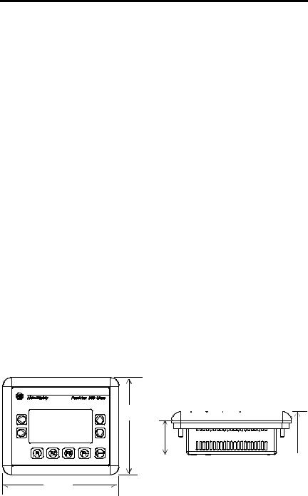
6 PanelView 300 Micro Terminal
Wiring and Safety Guidelines
Install the PanelView 300 Micro terminal using publication 70E, Electrical Safety Requirements for Employee Workplaces. In addition to the NFPA general guidelines, follow these recommendations:
•Route incoming power to the PanelView 300 Micro by a separate path from the communication cable.
•Where power and communication lines must cross, they should cross at right angles. Communication lines can be installed in the same conduit as low level DC I/O lines (less than 10 Volts).
•Grounding minimizes noise from Electromagnetic Interference (EMI) and is a safety measure in electrical installations. To avoid EMI, shield and ground cables appropriately.
A source for grounding recommendations is the National Electrical Code published by the National Fire Protection Association of Boston.
Mounting the Terminal
Enclosures
Mount the PanelView 300 Micro terminal in a panel or enclosure to protect the internal circuitry. The terminal meets NEMA 12/13 and 4X (indoor use) ratings only when properly mounted in a panel or enclosure with the equivalent rating.
Allow enough space within the enclosure for adequate ventilation. Consider heat produced by other devices in the enclosure. The ambient temperature around the PanelView 300 Micro must be between 0° and 55° C (32° and 131° F).
Make provisions for accessing the side panel of the terminal for wiring, maintenance and troubleshooting.
Mounting Dimensions
111 mm
(4.38 in.)
|
35 mm |
48 mm |
|||
|
(1.39 in.) |
(1.87 in.) |
133 mm
(5.23 in.)
41061-156-01(A)

|
PanelView 300 Micro Terminal |
7 |
Cutout Dimensions
Use the full size template shipped with the PV300 Micro to mark the cutout dimensions. The figure below shows a reduced scale cutout. A full scale template is also available inside the back cover of this document.
|
4.42 in. (112 mm) |
0.178 in. (4.5 mm) |
|||||||||||||
|
Diameter |
||||||||||||||
|
4.0 in. (102 mm) |
||||||||||||||
3.62 in.
(92 mm)
2.12 in.
(54 mm)
Clearances
Allow 51 mm (2.0 inches) of space on all sides of the terminal for adequate ventilation and maintenance.
|
2.0 in. (51 mm) |
|
2.0 in. (51 mm) |
41061-156-01(A)
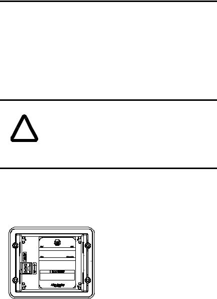
8 PanelView 300 Micro Terminal
Installing Terminal in Panel
Other than the tools required to make the panel cutout, the tools required for installation are:
•7 mm (M4) deep well socket wrench or nut driver
•small slotted screwdriver
•torque wrench (in. / lbs.)
To install the PV300 Micro in a panel:
|
ATTENTION |
• Disconnect all electrical power from the panel before |
|
|
making cutout. |
||
•Make sure area around the panel cutout is clear.
!• Take precautions so that metal cuttings do not enter any components already installed in panel.
•Failure to follow this warning may result in personal injury or damage to the panel components.
1.Cut an opening in the panel using the panel cutout provided with the terminal. Remove sharp edges or burrs.
2.Make sure the sealing gasket is properly positioned on the terminal (as shown below). This gasket forms a compression type seal. Do not use sealing compounds.
 Sealing Gasket
3. Place the terminal in the panel cutout.
41061-156-01(A)
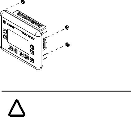
|
PanelView 300 Micro Terminal |
9 |
4. Install the 4 self-locking nuts, hand tight.
Self-Locking Nuts (4 used, 6 provided)
5.Alternately tighten the self-locking nuts until the terminal is held firmly against the panel. Tighten the nuts to a torque of 10 inch-pounds. Do not overtighten.
|
ATTENTION |
Mounting nuts must be tightened to a torque of 10 |
|
|
inch-pounds to provide a proper seal and to prevent |
||
|
! |
potential damage to the terminal. Allen-Bradley assumes no |
|
|
responsibility for water or chemical damage to the terminal |
||
|
or other equipment within the enclosure because of |
||
|
improper installation. |
||
41061-156-01(A)
10 PanelView 300 Micro Terminal
Connecting DC Power
The PV300 Micro terminal connects to a 24V dc power source. The table below shows the electrical ratings for the DC versions of the terminals. Electronic circuitry and an internal fuse protect the terminals from reverse polarity and over-voltage conditions.
|
Terminal Type |
Supply Voltage |
Power Consumption |
|
PV300 Micro |
11 to 30V dc |
2.5 Watts maximum |
|
(24V dc nominal) |
(0.105 Amps @24V dc) |
|
PV300 Micro terminal is designed for safe use when installed in a suitably rated NEMA Type 12, 13, 4X (indoor use only), IP54 or IP65 enclosure.
|
ATTENTION |
• Do not connect the PanelView terminal to an AC power |
|
|
source. Connecting to an AC power source will damage the |
||
|
terminal. |
!• Use only a Safety Extra Low-Voltage (SELV) power supply with an output rated between 11 — 30V dc as a power source for the PanelView 300 Micro. A SELV power supply does not exceed 42.4V dc.
The input power terminal block on the PanelView 300 Micro is removable and supports the following wiring types.
|
Wire Type |
Wire Size (2-wire maximum per terminal) |
|
Solid |
#16 to #22 AWG |
|
Stranded |
#18 to #22 AWG |
41061-156-01(A)
![]()
|
PanelView 300 Micro Terminal |
11 |
To connect DC power to the PanelView 300 Micro terminal:
1.Secure the DC power wires to the screw terminal block.
2.Secure the Functional Earth Ground wire to the screw terminal block.
•Substitution of components may impair suitability for Class I, Division 2.
!• Do not disconnect equipment unless power has been switched off and area is known to be non-hazardous.
•Do not connect or disconnect components unless power has been switched off.
•All wiring must comply with N.E.C. article 501-4(b).
3.Apply power (24V dc nominal) to the terminal.
+DC Positive
—DC Negative
 Functional Earth Ground
Removing and Installing the Power Terminal Block
You can remove and re-install the power terminal block for ease of installation, wiring and maintenance. The terminal block is pre-installed when shipped. Additional terminal blocks (quantity of 10) are available by ordering Catalog Number 2711-TBDC.
To remove the DC power terminal block:
1.Disconnect all electrical power from the panel. See Explosion Hazard Warning above.
2.Insert tip of small flat-blade screw driver into DC power terminal access slot.
41061-156-01(A)

12 PanelView 300 Micro Terminal
 Insert tip of screw driver here.
3.Gently push the blade of the screw driver away from the terminal block to release locking mechanism.
4.Remove DC power terminal block.
To re-install the DC power terminal block
Note: Install the terminal block with or without the power wires connected.
1.Disconnect all electrical power from the panel prior to installation. See Explosion Hazard Warning on previous page.
2.Position the terminal block at a 45° angle to the base surface and place lower edge of the wire connection side into the base.
3.Gently push the top of the terminal block back to a vertical position to snap in the locking tab.
Press terminal block  base in first with block leaning outward
Push top back to  vertical position
to lock-in.
41061-156-01(A)
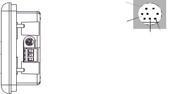
|
PanelView 300 Micro Terminal |
13 |
Using the Communications Port
The PanelView 300 Micro terminal is available in 2 versions.
|
Catalog Number |
Communication Port |
Communication Protocol |
|
2711-M3A18L1 |
RS-232 |
DF1 |
|
2711-M3A19L1 |
RS-232 |
DH485 |
Both versions have an identical RS-232 communications port with a MicroLogix 8-pin mini-DIN style connector. The only difference is the protocol firmware (DF1 or DH485) pre-loaded at the factory. Both versions of the protocol firmware are supplied with the PanelBuilder32 software. You can change the protocol by downloading the firmware to the terminal using the Windows PanelView MotherBoard Firmware Download Utility (WinMBFWDL) utility. This utility is included with the PanelBuilder32 software.

 RS-232
8-pin mini-DIN connector
 Port is used for both communications with a controller and to transfer application files.
|
2 |
1 |
|||||
|
5 |
3 |
|||||
Pin # Signal
1NC (No Connection)
2GND
3RTS
4RXD
5NC (No Connection)
6CTS
7TXD
8GND
The following table lists the communication parameters supported by each of the protocols on the RS-232 communications port.
|
Communication Link |
Communication Parameters |
|
RS-232 or DH-485 Link Point-to-Point |
|
|
Baud Rate: |
1200, 2400, 9600, 19.2K Baud |
|
Maximum Distance |
6.1 meters (20 feet) |
|
DF1 — Full Duplex Communication |
|
|
Baud Rate |
1200, 2400, 4800, 9600, 19.2K Baud |
|
Maximum Distance |
15.24 meters (50 feet) |
41061-156-01(A)

14 PanelView 300 Micro Terminal
Connecting to Controllers
This section lists the cables used by the PanelView 300 Micro to communicate with Allen-Bradley controllers and to operate on a DH-485 or DeviceNet network.
|
MicroLogix Controller |
Cable |
Cable Length |
|
|
Point-to-Point Communications with a |
1761-CBL-AM00, Series C |
0.5 meter (1.5 ft) |
|
|
MicroLogix 1000/1200/1500 controller |
|||
|
1761-CBL-HM02, Series C |
2 meter (6.5 ft) |
||
|
using either DF1 or DH485 protocol over an |
|||
|
2711-CBL-HM05, Series C |
5 meter (15 ft) |
||
|
RS-232 link. |
|||
|
2711-CBL-HM10, Series C |
10 meter (30 ft) |
||
|
SLC/PLC-5/ControlLogix Controller |
Cables |
Cable Length |
|
|
Point-to-Point Communications with a SLC, |
1761-CBL-AP00, Series C |
0.5 meter (1.5 ft) |
|
|
PLC-5 or ControlLogix processor or module |
|||
|
1761-CBL-PM02, Series C |
2 meter (6.5 ft) |
||
|
using either DF1 or DH485 protocol over an |
|||
|
2711-CBL-PM05, Series C |
5 meter (15 ft) |
||
|
RS-232 link. |
|||
|
2711-CBL-PM10, Series C |
10 meter (30 ft) |
||
|
Advanced Interface Converter (AIC+) |
Cables |
Cable Length |
|
|
Point-to-point connection between the |
1761-CBL-AM00, Series C |
0.5 meter (1.5 ft) |
|
|
PanelView 300 Micro and an AIC+ module |
|||
|
1761-CBL-APOO, Series C |
0.5 meter (1.5 ft) |
||
|
(Cat. No. 1761-NET-AIC). This connection |
|||
|
1761-CBL-PM02, Series C |
2 meter (6.5 ft) |
||
|
allows the DH-485 version of the 300 |
|||
|
Micro to operate on a DH-485 network. |
1761-CBL-HM02, Series C |
2 meter (6.5 ft) |
|
|
2711-CBL-PM05, Series C |
5 meter (15 ft) |
||
|
2711-CBL-HM05, Series C |
5 meter (15 ft) |
||
|
2711-CBL-PM10, Series C |
10 meter (30 ft) |
||
|
2711-CBL-HM10, Series C |
10 meter (30 ft) |
||
|
DeviceNet Interface (DNI) |
Cables |
Cable Length |
|
|
Point-to-Point connection between a |
1761-CBL-AM00, Series C |
0.5 meter (1.5 ft) |
|
|
PanelView 300 Micro and the DNI module |
|||
|
1761-CBL-HM02, Series C |
2 meter (6.5 ft) |
||
|
(Cat. No. 1761-NET-DNI). This connection |
|||
|
2711-CBL-HM05, Series C |
5 meter (15 ft) |
||
|
allows the DF1 version of the Micro 300 to |
|||
|
operate on a DeviceNet network. |
2711-CBL-HM10, Series C |
10 meter (30 ft) |
|
41061-156-01(A)

|
PanelView 300 Micro Terminal |
15 |
Bulletin 1761 or 2711-CBL-HMxx Cable Pinouts
These cables connect the PanelView 300 Micro terminal directly to a MicroLogix controller, AIC+ or DNI module for runtime communications.
|
8-Pin mini-DIN |
8-Pin mini-DIN |
|||||||||||||||||||
|
1 |
24V |
24V |
1 |
|||||||||||||||||
|
2 |
GND |
GND |
2 |
|||||||||||||||||
|
3 |
RTS |
RTS |
3 |
|||||||||||||||||
|
4 |
CTS |
CTS |
6 |
|||||||||||||||||
|
5 |
DCD |
DCD |
5 |
|||||||||||||||||
|
6 |
RXD |
RXD |
4 |
|||||||||||||||||
|
7 |
TXD |
TXD |
7 |
|||||||||||||||||
|
8 |
GND |
GND |
8 |
|||||||||||||||||
Bulletin 1761 or 2711-CBL-PMxx Cable Pinouts
These cables connect the PanelView 300 Micro terminal directly to a personal computer for application file transfers or to an SLC, PLC-5 or ControlLogix controller for runtime communications.
|
8-pin mini-DIN |
|||||||||||||||||||||
|
9-Pin D-Shell |
|||||||||||||||||||||
|
9 |
RI |
24V |
1 |
||||||||||||||||||
|
5 |
GND |
GND |
2 |
||||||||||||||||||
|
7 |
RTS |
RTS |
3 |
||||||||||||||||||
|
8 |
CTS |
CTS |
6 |
||||||||||||||||||
|
1 |
DCD |
DCD |
5 |
||||||||||||||||||
|
2 |
RXD |
RXD |
4 |
||||||||||||||||||
|
3 |
TXD |
TXD |
7 |
||||||||||||||||||
|
4 |
DTR |
GND |
8 |
||||||||||||||||||
|
6 |
DSR |
||||||||||||||||||||
41061-156-01(A)

16 PanelView 300 Micro Terminal
Transferring Application Files
Applications for the PanelView 300 Micro terminal are developed using PanelBuilder32 Software (Catalog Number 2711-ND3, V3.60 or later). You can transfer application files between a computer and the terminal over an RS-232 communication link using one of the following cables.
|
Download Cable |
Cable Length |
|
1761-CBL-PM02, Series C |
2 meter (6.5 ft) |
|
2711-CBL-PM05, Series C |
5 meter (15 ft) |
|
2711-CBL-PM10, Series C |
10 meter (30 ft) |
Three file transfer methods are available for the PanelView 300 Micro:
PanelBuilder32 Software
Supports the direct transfer of application files from PanelBuilder32 using an RS-232 link.
Windows PanelView File Transfer (WinPFT) Utility
Supports the direct transfer of PanelBuilder32 application files from WinPFT over an RS-232 link. The WinPFT utility is included with the PanelBuilder32 Software. RSLinx software may be required to transfer applications to the terminal for DH-485 and DF1 protocols.
This method is recommended for direct downloads to installed PanelView 300 Micro terminals using a portable or laptop computer.
Windows CE Pocket PanelView File Transfer (PocketPFT) Utility
Supports the direct transfer of PanelBuilder32 application files from the PocketPFT software over an RS-232 link. The PocketPFT software and an RS232 cable is available from Rockwell Software as part of the MaintenCE suite of tools. You will also need one of the recommended download cables.
This method is recommended for direct downloads to installed PanelView 300 Micro terminals using an HPC JORNADA portable CE computer, available only from Rockwell Software.
41061-156-01(A)
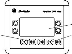
|
PanelView 300 Micro Terminal |
17 |
File Transfer Considerations
Because the communication port supports both runtime communications and application transfers,you must make sure the port is set properly.
For successful communications, the PV300 Micro and the communicating device must be set to the same communications settings and baud rate. The factory default setting is 9600 baud.
Downloaded Baud Rate Changes — After a successful application download, you may not be able to download another application. It is possible, the downloaded application was configured with a different run-time communication baud rate in the PanelBuilder32 software.
Run-Time Baud Rate Changes — After a successful application download, the PanelView 300 Micro may not be communicating with the logic controller. It is possible, the downloaded application was configured with a different communication baud rate than the connected logic controller.
To adjust the baud rate, you can either:
•enter Configuration Mode on the terminal and select the Communication Setup screen (looks similar to screen below). See page 18 to access Configuration Mode.
|
DF1 — Full Duplex |
||
|
F1 Comms |
N/8/1 |
|
|
F2 Baud |
9600 |
|
|
Press F2 to change |
F3 MORE |
F4 EXIT |
|
baud rate setting. |
 Current baud rate setting.
 Press F4 to save setting and exit.
•access the Communication Setup dialog from the Application Settings dialog in PanelBuilder32 and then redownload the application to the PV300 Micro.
41061-156-01(A)
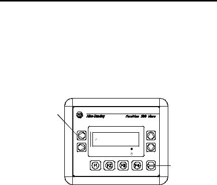
18 PanelView 300 Micro Terminal
Accessing Configuration Mode
The PanelView 300 Micro terminal, like all standard PanelView terminals, has configuration screens you can access to review or modify terminal settings.
1.Apply power to the PanelView 300 Micro as described in previous sections.
2.Simultaneously press both the Left and Right arrow keys on the front panel.
You will not be able to access Configuration mode if the arrow keys are assigned to objects in the terminal application.
Press and release both the Left and Right arrow keys
simultaneously to enter Configuration Mode.
CONFIGURATION MODE
Language
 Communication
Preset Operations
|
F1 RUN MODE |
C |
|
F2 RESET VIDEO |
F |
Enter Key
3.The Configuration Mode menu displays the various options. Using the up and down arrow keys, navigate through the configuration screens to review terminal information, communication settings, time/date settings, display settings, and the current language setting.
Changes to settings take affect immediately (without powering off the terminal).
Resetting the Terminal
You can reset the PanelView 300 Micro from the front panel without having to remove and then re-apply power. A 3-key reset from the front panel is equivalent to a power cycle.
To reset, the PanelView 300 Micro:
Press and release both the Left and Right arrow keys and the Enter key simultaneously. The terminal resets.
41061-156-01(A)
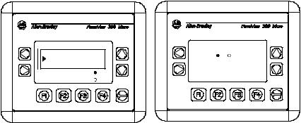
|
PanelView 300 Micro Terminal |
19 |
Comm and Fault Indicators
The PanelView 300 Micro has a Comm (communication) and Fault (error) status indicator. These indicators are visible from Configuration Mode when selecting the Communication screen. Use the Comm and Fault indicators to isolate operating problems.
|
CONFIGURATION MODE |
DF1 — Full Duplex |
|||
|
Language |
Comm |
Fault |
||
|
Communication |
||||
|
Preset Operations |
C |
PanelView Online |
||
|
F1 RUN MODE |
F3 MORE |
F4 EXIT |
||
|
F2 RESET VIDEO |
F |
|||
|
Indicator |
State |
Indicates |
|
Comm |
ON (steady state solid fill) |
Normal Operating (no communications fault) |
|
OFF (no fill) |
Fault detected. Verify: |
|
|
• controller is in run mode. |
||
|
• communication settings for terminal and |
||
|
controller. |
||
|
• terminal and controller node addresses. |
||
|
• terminal to controller connections. |
||
|
Blinking (flashing) |
No communications established. For DF1 terminals, |
|
|
the Comm indicator flashes until an application is |
||
|
loaded. |
||
|
Fault |
OFF (no fill pattern) |
Normal operating state |
|
ON (steady state solid fill) |
Fault detected. Reset or cycle power to the terminal. |
|
|
If the fault remains the terminal requires servicing. |
||
|
Blinking (flashing) |
Hardware is functioning but no application is loaded |
|
|
in the terminal or the current application is |
||
|
corrupted. Reload the application file into the |
||
|
terminal. |
||
41061-156-01(A)

20 PanelView 300 Micro Terminal
Troubleshooting and Maintenance
The troubleshooting chart below lists common operating problems, causes and corrective steps.
|
Problem |
Causes |
Corrective Action |
||
|
Terminal does not powerup |
1. |
Improper connection to |
1. |
Verify correct voltage at |
|
power source. |
power terminals. |
|||
|
2. |
Incorrect input voltage level. |
2. Verify power source output |
||
|
3. |
Power terminal block |
is between 11 — 30V dc. |
||
|
3. |
Snap power terminal block |
|||
|
removed. |
onto base on back of |
|||
|
4. |
DC power wires reversed. |
terminal. |
||
|
4. |
Connect DC power positive |
|||
|
and negative wires to |
||||
|
correct terminals. |
||||
|
Application File will not |
1. |
Communication cable |
1. |
Check communication cable |
|
download (first download) |
disconnected. |
type and connections. |
||
|
2. |
Incorrect baud rate or |
2. |
Verify computer and |
|
|
communication settings. |
terminal are set to same |
|||
|
3. |
Incorrect computer COM |
communication settings. |
||
|
3. |
Verify correct COM port |
|||
|
port selection. |
number in WinPFT or |
|||
|
PanelBuilder32 software. |
||||
|
Application File will not |
1. |
Incorrect communication or |
1. |
Verify computer and |
|
download (subsequent |
baud rate settings. |
terminal have same |
||
|
downloads) |
communication settings. |
|||
|
Change settings in |
||||
|
Communication setup |
||||
|
screen of terminal. |
||||
|
No communication with |
1. |
Communications Comm |
1. |
Check Comm indicator. See |
|
MicroLogix, ControlLogix, SLC |
fault. |
page 19. |
||
|
or PLC controller. |
2. |
Incorrect baud rates. |
2. |
Verify controller and |
|
3. |
Controller not in run mode. |
terminal set to same baud. |
||
|
3. |
Place controller in run mode. |
|||
|
4. |
Incorrect terminal node and |
4. |
Verify node addresses. |
|
|
max node addresses. |
||||
|
No communication with |
1. |
Incorrect node address of |
1. |
Verify node address of |
|
controller but Comm indicator |
controller. |
controller. |
||
|
is active. |
2. |
Inhibit bit set as default on |
2. |
Change inhibit bit setting. |
|
PLC channel status screen. |
||||
|
Clock Module Battery Low |
1. |
Internal parameters corrupt. |
1. |
Reload application and cycle |
|
message displayed. |
power to terminal. |
|||
|
2. |
Clock module battery failure. |
2. Replace terminal. |
||
|
Screen objects do not |
1. |
Communication problem. |
1. |
Check status of Comm |
|
function. |
indicator. |
|||
41061-156-01(A)
|
PanelView 300 Micro Terminal |
21 |
|||||
|
Problem |
Causes |
Corrective Action |
||||
|
No communications with |
1. |
Communications Comm |
1. |
Check Comm indicator. See |
||
|
computer. |
fault. |
page 19. |
||||
|
2. |
Incorrect baud rate or |
2. |
Verify computer and |
|||
|
communication settings. |
terminal are at same baud. |
|||||
|
3. |
Incorrect terminal node or |
3. |
Verify node addresses. |
|||
|
max node address. |
||||||
|
4. |
Computer fault. |
4. |
Refer to computer manual. |
|||
|
5. |
Communications driver not |
5. |
Refer to RSLinx online help |
|||
|
properly loaded. |
or manual. |
|||||
|
Application filename appears |
1. |
Application file invalid. |
1. |
Download application to |
||
|
as ****** on Terminal Info |
terminal. |
|||||
|
screen. |
2. |
Application unusable |
2. |
Download new application. |
||
|
because of error. |
||||||
|
Screen objects not visible. |
1. |
Correct power not applied. |
1. |
Verify power connections. |
||
|
2. |
Contrast not set correctly. |
2. |
Access Screen Setup from |
|||
|
Configuration Mode and |
||||||
|
3. |
Terminal in screen saver |
adjust display contrast. |
||||
|
3. |
Access Screen Setup from |
|||||
|
mode. |
Configuration Mode to |
|||||
|
check if terminal is in Screen |
||||||
|
Saver Mode. |
||||||
|
Values do not update on |
1. |
Terminal not communicating |
1. |
Check status of Comm |
||
|
display but appear as asterisks |
with logic controller. |
indicator. See problem “No |
||||
|
**** |
communication with |
|||||
|
2. |
Value is invalid or exceeds |
controller” for details. |
||||
|
2. |
Change the field width set |
|||||
|
the field width for object. |
for the object. |
|||||
|
LCD display is difficult to view. |
1. |
Display contrast level set |
1. |
Access Configuration mode |
||
|
incorrectly. |
and adjust the display |
|||||
|
contrast level. |
||||||
|
Can’t Configuration Mode |
1. |
Left and right arrow keys are |
1. |
Contact Technical Support |
||
|
when pressing Left and Right |
assigned to screen objects |
for assistance. |
||||
|
arrow keys simultaneously. |
in the terminal application. |
|||||
|
No network found. |
1. |
Node setting of controller |
1. |
Change node address in |
||
|
does not match application. |
application to match |
|||||
|
2. |
Controller data file does not |
controller node address. |
||||
|
2. |
Verify data file elements for |
|||||
|
have enough elements. |
all tag addresses. |
|||||
41061-156-01(A)

22 PanelView 300 Micro Terminal
Maintenance
The PanelView 300 Micro has no internal components that are user accessible. The rear cover is not removable, therefore, you should not remove it for troubleshooting or maintenance. The real-time clock battery and the LCD display backlight are not replaceable.
To clean the display window of the PanelView 300 Micro:
1.Disconnect power from the terminal at the power source.
2.Use a clean sponge or soft cloth to clean with a mild soap or detergent to clean the display. Do not scrub, use brushes, abrasive cleaners or solvents.
3.Dry the display with a chamois or moist cellulose sponge to avoid water spots.
Accessories
The following accessories are available for the PanelView 300 Micro.
PanelBuilder32 Software
|
Catalog No. |
Description |
Version |
|
2711-ND3 |
PanelBuilder32 Software for developing applications |
3.60 or later |
|
for the line of Standard PanelView terminals. |
||
DC Power Input Terminal Block
|
Catalog No. |
Description |
Quantity |
|
2711-TBDC |
Removable (3-position screw) DC Power Input Terminal Block |
10 |
Communication Cables
|
Cable |
Connector Type |
Cable Length |
|
1761-CBL-AM00, Series C |
8-pin mini-DIN to 8-pin mini-DIN |
0.5 meter (1.5 ft) |
|
1761-CBL-AP00, Series C |
8-pin mini-DIN to 9-pin D-Shell |
0.5 meter (1.5 ft) |
|
1761-CBL-PM02, Series C |
8-pin mini-DIN to 9-pin D-Shell |
2 meter (6.5 ft) |
|
1761-CBL-HM02, Series C |
8-pin mini-DIN to 8-pin mini-DIN |
2 meter (6.5 ft) |
|
2711-CBL-PM05, Series C |
8-pin mini-DIN to 9-pin D-Shell |
5 meter (15 ft) |
|
2711-CBL-HM05, Series C |
8-pin mini-DIN to 8-pin mini-DIN |
5 meter (15 ft) |
|
2711-CBL-PM10, Series C |
8-pin mini-DIN to 9-pin D-Shell |
10 meter (30 ft) |
|
2711-CBL-HM10, Series C |
8-pin mini-DIN to 8-pin mini-DIN |
10 meter (30 ft) |
41061-156-01(A)

|
PanelView 300 Micro Terminal |
23 |
Specifications
|
Electrical |
||||||||||||
|
Supply Voltage Limits |
11 to 30V dc (24V dc nominal) |
|||||||||||
|
Power Consumption |
2.5W maximum (0.105A @24V dc) |
|||||||||||
|
Mechanical |
||||||||||||
|
Enclosure |
NEMA Type 12/13, 4X (indoor use only), IP54, IP65 |
|||||||||||
|
Weight |
284 grams (10 oz.) |
|||||||||||
|
Dimensions |
133 (H) x 111 (W) x 48 (D) mm |
|||||||||||
|
5.23 (H) x 4.38 (W) x 1.87 (D) inches |
||||||||||||
|
Installed Depth |
35 mm (1.39 inches) |
|||||||||||
|
Display |
||||||||||||
|
Type |
Liquid Crystal Display (LCD) with LED backlighting |
|||||||||||
|
Size |
73 mm (w) x 42 mm (h) |
|||||||||||
|
2.87 in. (w) x 1.67 in. (h) |
||||||||||||
|
Pixels |
128 x 64 |
|||||||||||
|
Environment |
||||||||||||
|
Operating Temperature |
° |
to 55 |
° |
C (32 |
° |
° |
F) |
|||||
|
0 |
to 131 |
|||||||||||
|
Storage Temperature |
° |
to 85 |
° |
C (-4 |
° |
to 188 |
° |
F) |
||||
|
-20 |
||||||||||||
|
Humidity (non-condensing) |
° |
° |
° |
° |
||||||||
|
5 to 95% at 0 |
to 55 C (32 to 131 |
F) |
||||||||||
|
Heat Dissipation |
2.5W (8.5 BTU/Hour) |
|||||||||||
|
Impulse Shock |
30G operating, 50G non-operating |
|||||||||||
|
Vibration |
2G up to 2,000 Hz operating |
|||||||||||
|
Agency Certifications |
||||||||||||
|
When product is marked: |
UL |
|||||||||||
|
CE marked for all applicable directives |
||||||||||||
|
c-UL Class I Div 2 Hazardous(1) |
(1) CSA certification — Class I, Division 2, Group A,B,C,D or nonhazardous locations
41061-156-01(A)

24 PanelView 300 Micro Terminal
41061-156-01(A)

Notice d’installation
Français
Terminal PanelView 300 Micro
(Références 2711-M3A18L1, 2711-M3A19L1)
|
Sommaire : |
|
|
Pour plus d’informations …………………………………………………………….. |
26 |
|
Conformité aux directives de l’Union européenne …………………………. |
26 |
|
Emplacements dangereux…………………………………………………………… |
27 |
|
Câblage et consignes de sécurité………………………………………………… |
28 |
|
Dimensions de montage …………………………………………………………….. |
28 |
|
Branchement de l’alimentation c.c. ……………………………………………… |
32 |
|
Utilisation du port de communication ………………………………………….. |
35 |
|
Accès au mode de configuration …………………………………………………. |
40 |
|
Réinitialisation du terminal ………………………………………………………… |
40 |
|
Indicateurs de communication et de défauts ………………………………… |
41 |
|
Dépannage et maintenance………………………………………………………… |
42 |
|
Maintenance …………………………………………………………………………….. |
45 |
|
Caractéristiques ………………………………………………………………………… |
46 |
41061-156-01(A)

26 Terminal PanelView 300 Micro
Pour plus d’informations
|
Pour |
Se reporter au |
N° de publication |
|
document |
||
|
Une description plus détaillée sur le 300 Micro |
Manuel d’utilisation des |
2711-UM014A-FR-P |
|
et autres terminaux PanelView standard. |
terminaux PanelView |
|
Pour obtenir l’une de ces publications, vous pouvez :
•charger une version électronique gratuite à partir du CD d’installation PanelBuilder32
•charger une version électronique gratuite à partir d’internet à l’adresse suivante : www.ab.com/manuals/eoi or www.theautomationbookstore.com
Pour acheter une publication :
•visitez le site www.theautomationbookstore.com et passez votre commande
•contactez votre distributeur local ou votre représentant de Rockwell Automation
Conformité aux directives de l’Union européenne
Si ce produit porte le marquage CE, son installation dans les pays de l’Union européenne et de l’Espace Economique Européen a été approuvée. Il a été conçu et testé en conformité avec les directives suivantes.
Directive CEM
Cet appareil a été testé en termes de compatibilité électromagnétique (CEM) selon la directive 89/336/EEC à l’aide d’un cahier des charges et d’après les normes suivantes, en totalité ou partie :
•EN 50081-2 Compatibilité électromagnétique – Norme générique émission – Partie 2 : Environnement industriel
•EN 50082-2 Compatibilité électromagnétique – Norme générique immunité – Partie 2 : Environnement industriel.
Ce produit décrit dans le présent document est conçu pour une utilisation en environnement industriel.
41061-156-01(A)

|
Terminal PanelView 300 Micro |
27 |
Emplacements dangereux
Cet équipement ne convient qu’à une utilisation dans un environnement de Classe 1, Division 2, Groupes A, B, C, D ou non dangereux. L’avertissement ATTENTION suivant concerne l’utilisation en environnements dangereux.
|
DANGER |
Risque d’explosion |
•La substitution de composants peut rendre cet équipement impropre à une utilisation en environnement de Classe I,
!Division 2.
•Ne pas débrancher l’équipement tant que l’alimentation électrique n’a pas été coupée et que la zone n’est pas sans danger.
•Ne pas brancher ou débrancher de composants tant que l’alimentation électrique n’a pas été coupée.
•Les câblages doivent tous être conformes à la norme N.E.C. article 501-4(b).
•Les équipements périphériques doivent être appropriés à l’endroit dans lequel ils seront utilisés.
Utiliser exclusivement les câbles de communication suivants dans les environnements dangereux de Classe 1, Division 2.
|
Classification relative aux |
Câbles de communication |
|
environnements |
|
|
1761-CBL-PM01, série C |
|
|
1761-CBL-HM02, série C |
|
|
1761-CBL-AM00, série C |
|
|
Emplacements dangereux de Classe 1, |
1761-CBL-AP00, série C |
|
Division 2 |
2711-CBL-PM05, série C |
|
2711-CBL-HM05, série C |
|
|
2711-CBL-PM10, série C |
|
|
2711-CBL-HM10, série C |
|
41061-156-01(A)
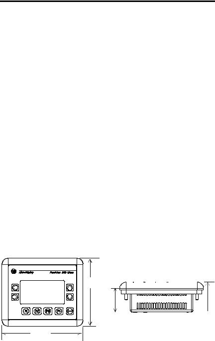
28 Terminal PanelView 300 Micro
Câblage et consignes de sécurité
Installer le terminal PanelView 300 Micro en suivant les instructions figurant dans la publication américaine 70E, Electrical Safety Requirements for Employee Workplaces. Outre les consignes de sécurité générales NFPA (Association nationale de protection contre l’incendie), il convient de suivre les recommandations suivantes :
•Acheminer l’alimentation d’arrivée du PanelView 300 Micro par le biais d’un chemin séparé du câble de communication.
•Lorsque les lignes de courant et de communication doivent se croiser, elles doivent se croiser à angle droit. Les lignes de communication peuvent être installées dans le même conduit que les lignes d’E/S c.c. de bas niveau (de moins de 10 volts).
•La mise à la terre permet de réduire les interférences électromagnétiques (EMI) et constitue une mesure de sécurité sur les installations électriques. Pour éviter les interférences électromagnétiques, il convient de blinder les câbles et de les relier à la terre de manière appropriée.
Pour plus d’informations relatives aux recommandations en matière de mise à la terre, se reporter au National Electrical Code publié par la National Fire Protection Association of Boston.
Montage du terminal
Armoires
Monter le terminal PanelView 300 Micro dans un panneau ou une armoire pour protéger les circuits internes. Le terminal est conforme aux normes NEMA 12/13 et 4X (s’appliquant à une utilisation sous-abri), à condition qu’il soit monté correctement dans un panneau ou une armoire conformément aux normes appropriées. Veiller à laisser un espace suffisant à l’intérieur de l’armoire pour permettre une ventilation adéquate. Prendre en compte la chaleur produite par les autres dispositifs installés dans l’armoire. La température ambiante autour du PanelView 300 Micro doit être comprise entre 0 ° et 55 ° C (32 ° et 131 ° F).
Prévoir les accès au panneau latéral du terminal pour le câblage, la maintenance et le dépannage.
Dimensions de montage
111 mm
(4,38 in.)
|
35 mm |
48 mm |
|||
|
(1,39 in.) |
(1,87 in.) |
133 mm
(5,23 in.)
41061-156-01(A)
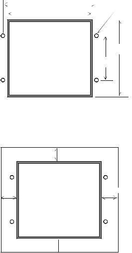
|
Terminal PanelView 300 Micro |
29 |
Dimensions de la découpe
Utiliser le gabarit grandeur nature fourni avec le PV300 Micro pour déterminer les dimensions de la découpe. La figure ci-dessous montre la découpe à échelle réduite. Un gabarit grandeur nature est également disponible dans l’avant-derrière de couverture de ce document.
|
112 mm (4,42 in.) |
4,5 mm (0,178 in.) |
|||||||||||||
|
Diamètre |
||||||||||||||
|
102 mm (4,0 in.) |
||||||||||||||
92 mm
(3,62 in.)
54 mm
(2,12 in.)
Espacements
Laisser 51 mm (2,0 in.) d’espace sur tous les cô tés du terminal afin d’assurer une ventilation adéquate et un accès pour la maintenance.
|
51 mm (2,0 in.) |
|
51 mm (2,0 in.) |
41061-156-01(A)
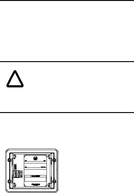
30 Terminal PanelView 300 Micro
Installation du terminal dans un panneau
Outre les outils requis pour découper le panneau, les outils suivants sont nécessaires pour l’installation :
•une clé à tube de grande profondeur de 7 mm (M4) ou une clé à pipe
•un petit tournevis pour écrous à fente
•une clé dynamométrique
Pour installer le terminal PV300 Micro dans un panneau :
|
ATTENTION |
• Déconnecter toute alimentation électrique du panneau avant |
|
|
de réaliser la découpe. |
||
•Vérifier que l’espace environnant la découpe du panneau
!est dégagé.
•Prendre des précautions afin d’éviter que des copeaux métalliques ne pénètrent dans les composants, quels qu’ils soient, déjà installés dans le panneau.
•Si ces recommandations ne sont pas respectées, il y a risque de blessures ou dommages.
1.Couper une ouverture dans le panneau à l’aide du gabarit fourni avec le terminal. Eliminer les arêtes vives.
2.Veiller à ce que le joint d’étanchéité soit correctement positionné sur le terminal (comme indiqué ci-dessous). Ce joint forme une étanchéité de type compression. Ne pas utiliser de produit d’étanchéité.
 Joint d’étanchéité
3. Placer le terminal dans la découpe du panneau.
41061-156-01(A)
![]()
|
Terminal PanelView 300 Micro |
31 |
4. Installer les 4 écrous autobloquants en les serrant à la main.
Ecrous autobloquants
(4 utilisés, 6 fournis)
5.Serrer les écrous autobloquants en alternance jusqu’à ce que le terminal soit fermement maintenu contre le panneau. Serrer les écrous à un couple de
10 lb-in (1,2 Nm). Ne pas trop serrer.
|
ATTENTION |
Les écrous de montage doivent être serrés à un couple de |
|
|
10 lb-in (1,2 Nm) afin d’assurer un joint approprié et |
||
|
d’éviter des dommages potentiels au terminal. |
!dommages qui auraient été engendrés par de l’eau ou des
produits chimiques sur le terminal ou autre équipement, inclus dans l’armoire, du fait d’une mauvaise installation.Allen-Bradley ne saurait être tenu pour responsable des
41061-156-01(A)

32 Terminal PanelView 300 Micro
Branchement de l’alimentation c.c.
Le terminal PV300 Micro est raccordé à une source d’alimentation de 24 V c.c. Le tableau ci-dessous indique les valeurs électriques nominales pour les terminaux version c.c. Les circuits électroniques et les fusibles internes protègent le terminal contre l’inversion de polarité et les surtensions.
|
Type de terminal |
Tension d’alimentation |
Consommation d’énergie |
|
PV300 Micro |
de 11 à 30 V c.c. |
2,5 Watts maximum |
|
(24 V c.c. nominal) |
(0,105 A @ 24 V c.c.) |
|
Le terminal PV300 Micro a été conçu pour une utilisation en toute sécurité lorsqu’il est installé dans un panneau conforme aux normes NEMA Type 12, 13, 4X (uniquement utilisation sous abri), IP54 ou IP65.
|
ATTENTION |
• Ne pas raccorder le terminal PanelView à une source de |
|
|
courant c.a. Le fait de le raccorder à une source de courant |
||
|
c.a. risque d’endommager le terminal. |
!• Pour l’alimentation du PanelView 300 Micro, utiliser uniquement une source de courant à tension extrêmement faible de type haute sécurité (SELV) avec une sortie comprise entre 11 et 30 V c.c. Une alimentation de type haute sécurité (SELV) ne dépasse pas 42,4 V c.c.
Le bornier d’alimentation d’entrée est amovible sur le PanelView 300 Micro et permet l’utilisation des types de câblage suivants.
|
Type de câble |
Section des câbles |
|
(2 câbles maximum par borne) |
|
|
Plein |
calibre de 16 à 22 |
|
Torsadé |
calibre de 18 à 22 |
41061-156-01(A)

|
Terminal PanelView 300 Micro |
33 |
Pour raccorder le terminal PanelView 300 Micro à une source de courant c.c. :
1.Fixer les câbles d’alimentation c.c. au bornier à vis.
2.Fixer le câble de mise à la terre au bornier à vis.
|
DANGER |
Risque d’explosion |
•La substitution de composants peut rendre cet équipement impropre à une utilisation en environnement de Classe 1,
!Division 2.
•Ne pas débrancher l’équipement tant que l’alimentation électrique n’a pas été coupée et que la zone n’est pas sans danger.
•Ne pas brancher ou débrancher de composants tant que l’alimentation électrique n’a pas été coupée.
•Les câblages doivent tous être conformes à la norme N.E.C. article 501-4(b).
3.Appliquer la source d’alimentation (24 V c.c. nominal) au terminal.
+c.c. positif
—c.c. négatif
Mise à la terre
Retrait et installation du bornier d’alimentation
Le bornier d’alimentation peut être retiré et réinstallé afin de faciliter l’installation, le câblage et la maintenance. Le bornier externe est préinstallé à la livraison. Les terminaux supplémentaires (au nombre de 10) sont disponibles sur commande, référence 2711-TBDC.
Pour retirer le bornier d’alimentation c.c. :
1.Déconnecter toute alimentation électrique du panneau. Se reporter à l’avertissement relatif au Risque d’explosion.
2.Insérer le bout d’un tournevis fin à lame plate dans la fente d’accès du bornier d’alimentation c.c.
41061-156-01(A)

34 Terminal PanelView 300 Micro
 Insérer le bout du tournevis à cet endroit.
3.Ecarter doucement la lame du tournevis du bornier en poussant afin de libérer le mécanisme de verrouillage.
4.Retirer le bornier d’alimentation c.c.
Pour réinstaller le bornier d’alimentation c.c.
Remarque : Le bornier peut être installé, que les câbles d’alimentation soient connectés ou non.
1.Déconnecter toute alimentation électrique du panneau avant de procéder à l’installation. Se reporter à l’avertissement relatif au Risque d’explosion, page précédente.
2. Incliner le bornier à 45° et placer le cô té connecteurs dans la base.
3.Pousser doucement le haut du bornier à nouveau en position verticale pour qu’il s’enclenche dans l’ergot de blocage.
Enfoncer d’abord la base du bornier, câbles orientés vers l’extérieur
Pousser le haut du bornier en arrière en position verticale afin de le verrouiller.
41061-156-01(A)

|
Terminal PanelView 300 Micro |
35 |
Utilisation du port de communication
Deux versions de terminal PanelView 300 Micro sont disponibles.
|
Référence |
Port de communication |
Protocole de |
|
communication |
||
|
2711-M3A18L1 |
RS-232 |
DF1 |
|
2711-M3A19L1 |
RS-232 |
DH485 |
Les deux versions sont pourvues d’un port identique de communication RS-232 avec un connecteur à 8 broches de type mini-DIN. La seule différence réside dans le firmware du protocole (DF1 ou DH485) qui est préchargé en usine. Les deux versions de firmware sont fournies avec le logiciel PanelBuilder32. Le protocole peut être changé en chargeant le firmware sur le terminal à l’aide de l’utilitaire Windows WinMBFWDL (Windows PanelView MotherBoard Firmware Download Utility). Cet utilitaire est inclus dans le logiciel PanelBuilder32.

 RS-232
avec connecteur 8 broches de type mini-DIN
 Ce port est utilisé pour les deux types de communication avec un automate et pour transférer des fichiers d’application.
|
2 |
1 |
|||||
|
5 |
3 |
|||||
Broche n° Signal
1NC (Pas de connexion)
2GND
3RTS
4RXD
5NC (Pas de connexion)
6CTS
7TXD
8GND
Le tableau suivant énumère les paramètres de communication reconnus par chacun des protocoles sur le port de communication RS-232.
|
Interface de communication |
Paramètres de communication |
|
Interface point à point RS-232 ou DH-485 |
|
|
Vitesse en bauds |
1200, 2400, 9600, 19,2 Kbauds |
|
Distance maximale |
6,1 mètres (20 pieds) |
|
DF1 – Communication full duplex |
|
|
Vitesse en bauds |
1200, 2400, 4800, 9600, 19,2 Kbauds |
|
Distance maximale |
15,24 mètres (50 pieds) |
41061-156-01(A)
 Loading…