-
Contents
-
Table of Contents
-
Troubleshooting
-
Bookmarks
Quick Links
Kinetix 6000 Multi-axis
Servo Drive
Catalog Numbers
2094-AC05-MP5, 2094-AC05-M01,
2094-AC09-M02, 2094-AC16-M03,
2094-AC32-M05, 2094-BC01-MP5,
2094-BC01-M01, 2094-BC02-M02,
2094-BC04-M03, 2094-BC07-M05
2094-AC05-MP5-S, 2094-AC05-M01-S,
2094-AC09-M02-S, 2094-AC16-M03 -S,
2094-AC32-M05-S, 2094-BC01-MP5-S,
2094-BC01-M01-S, 2094-BC02-M02-S,
2094-BC04-M03-S, 2094-BC07-M05-S
2094-AMP5, 2094-AM01, 2094-AM02,
2094-AM03, 2094-AM05, 2094-BMP5,
2094-BM01, 2094-BM02, 2094-BM03,
2094-BM05
2094-AMP5-S, 2094-AM01-S,
2094-AM02-S, 2094-AM03-S,
2094-AM05-S, 2094-BMP5-S,
2094-BM01-S, 2094-BM02-S,
2094-BM03-S, 2094-BM05-S
2094-BSP2
User Manual
Troubleshooting
Summary of Contents for Rockwell Automation Allen-Bradley Kinetix 6000
Document Update
Kinetix 6000 Multi-axis Servo Drives User Manual
Catalog Numbers
Kinetix 6000 Multi-axis Servo Drives
Integrated Axis Modules (IAM)
Axis Modules (AM)
Page 195
Catalog Numbers (230V)
2094-AC05-MP5-S
2094-AC05-MP5
2094-AC05-M01-S
2094-AC05-M01
2094-AC09-M02-S
2094-AC09-M02
2094-AC16-M03-S
2094-AC16-M03
2094-AC32-M05-S
2094-AC32-M05
2094-AMP5-S
2094-AMP5
2094-AM01-S
2094-AM01
2094-AM02-S
2094-AM02
2094-AM03-S
2094-AM03
2094-AM05-S
2094-AM05
This publication corrects errors in the Kinetix 6000 drive dimensions. The
updated information distinguishes the dimensional differences between series A
drives and series B drives. Series B drives exist for all 2094-BCxx-Mxx-S IAM
modules and 2094-BMxx-S AM (460V) modules.
Use this document in conjunction with the Kinetix 6000 Multi-axis Servo Drives
User Manual, publication 2094-UM001D-EN-P.
No changes were necessary for the IAM module dimensions on this page, other
than to state that these dimensions apply to series A and series B drives.
Catalog Numbers (460V)
2094-BC01-MP5-S
2094-BC01-MP5
2094-BC01-M01-S
2094-BC01-M01
2094-BC02-M02-S
2094-BC02-M02
2094-BC04-M03-S
2094-BC04-M03
2094-BC07-M05-S
2094-BC07-M05
2094-BMP5-S
2094-BMP5
2094-BM01-S
2094-BM01
2094-BM02-S
2094-BM02
2094-BM03-S
2094-BM03
2094-BM05-S
2094-BM05
Table 102 — Seven-segment Status Indicator Error Codes
Error
Fault Message — Logix
Code
Designer (HIM)
No Error Code Displayed
BusUndervoltage Fault
E00
(Blown fuse)
MotorOvertemp Fault
E04
(Motor Overtemp)
DriveOvercurrent Fault
E05
(Power Fault)
HardOvertravel Fault
E06
(+/- Hard Overtravel)
MotFeedbackFault
E07
(Motor Feedback Loss)
The following list of problematic symptoms (no error code shown) and faults
with assigned error codes is designed to help you resolve anomalies.
When a fault is detected, the seven-segment status indicator displays an E
followed by the flashing of the two-digit error code, one digit at a time. This is
repeated until the error code is cleared.
Anomaly or Symptom
Potential Cause
No AC power or auxiliary logic power.
Power (PWR) indicator not ON
Internal power supply malfunction.
Motor wiring error.
Motor jumps when first
enabled
Incorrect motor chosen.
Digital I/O not working
I/O power supply disconnected.
correctly
A blown fuse was detected on
Blown fuse.
the inverter PCB
• High motor ambient temperature
and/or
• Excessive current
Motor thermal switch tripped
Motor wiring error.
Incorrect motor selection.
Motor cables shorted.
Motor winding shorted internally.
Kinetix 6000 drive temperature too high.
Self-protection of the
Intelligent Power Module
(IPM) is indicating a major
power related fault condition.
Operation above continuous power rating and/
or product environmental ratings.
Kinetix 6000 drive has a short circuit,
overcurrent, or failed component.
Axis moved beyond the
physical travel limits in the
Dedicated overtravel input is inactive.
positive/negative direction.
The feedback wiring is open, shorted, or missing.
Rockwell Automation Publication 2094-UM001J-EN-P — March 2017
Troubleshooting the Kinetix 6000 Drive System
Possible Resolution
Verify AC control power is applied to the
Kinetix 6000 system.
Call your Rockwell Automation sales representative
to return module for repair.
• Check motor wiring.
• Run Hookup test in the Logix Designer
application.
Verify the proper motor is selected.
Verify connections and I/O power source.
Call your Rockwell Automation sales representative
to return module for repair.
• Operate within (not above) the continuous
torque rating for the ambient temperature
40 °C (104 °F) maximum.
• Lower ambient temperature, increase motor
cooling.
Check motor wiring at MF connector on the IAM/
AM module.
Verify the proper motor has been selected.
Verify continuity of motor power cable and
connector.
Disconnect motor power cables from the motor. If
the motor is difficult to turn by hand, consider
replacing the motor.
• Check for clogged vents or defective fan.
• Make sure cooling is not restricted by
insufficient space around the unit.
• Verify ambient temperature is not too high.
• Operate within the continuous power rating.
• Reduce acceleration rates.
• Reduce deceleration rates.
Remove all power and motor connections, and
preform a continuity check from the DC bus to the
U, V, and W motor outputs. If a continuity exists,
check for wire fibers between terminals, or send
drive in for repair.
• Check wiring.
• Verify motion profile.
• Verify axis configuration in software.
• Check motor encoder wiring.
• Run Hookup test in the Logix Designer
application.
Chapter 7
167
Rockwell Automation Publication 2094-UM001H-EN-P — June 2013
165
Troubleshooting the Kinetix 6000 Drive System
Chapter 7
Kinetix 6000 Drive System Error Codes
The following list of problematic symptoms (no error code shown) and faults
with assigned error codes is designed to help you resolve anomalies.
When a fault is detected, the seven-segment status indicator displays an E
followed by the flashing of the two-digit error code, one digit at a time. This is
repeated until the error code is cleared.
Table 99 — Seven-segment Status Indicator Error Codes
Error
Code
Fault Message — Logix
Designer (HIM)
Anomaly or Symptom
Potential Cause
Possible Resolution
No Error Code Displayed
Power (PWR) indicator not ON
No AC power or auxiliary logic power.
Verify AC control power is applied to the
Kinetix 6000 system.
Internal power supply malfunction.
Call your Rockwell Automation sales representative
to return module for repair.
Motor jumps when first
enabled
Motor wiring error.
• Check motor wiring.
• Run Hookup test in the Logix Designer
application.
Incorrect motor chosen.
Verify the proper motor is selected.
Digital I/O not working
correctly
I/O power supply disconnected.
Verify connections and I/O power source.
E00
BusUndervoltage Fault
(Blown fuse)
A blown fuse was detected on
the inverter PCB
Blown fuse.
Call your Rockwell Automation sales representative
to return module for repair.
E04
MotorOvertemp Fault
(Motor Overtemp)
Motor thermal switch tripped
• High motor ambient temperature
and/or
• Excessive current
• Operate within (not above) the continuous
torque rating for the ambient temperature 40 °C
(104 °F) maximum.
• Lower ambient temperature, increase motor
cooling.
Motor wiring error.
Check motor wiring at MF connector on the IAM/AM
module.
Incorrect motor selection.
Verify the proper motor has been selected.
E05
DriveOvercurrent Fault
(Power Fault)
Self-protection of the
Intelligent Power Module
(IPM) is indicating a major
power related fault condition.
Motor cables shorted.
Verify continuity of motor power cable and
connector.
Motor winding shorted internally.
Disconnect motor power cables from the motor. If
the motor is difficult to turn by hand, consider
replacing the motor.
Kinetix 6000 drive temperature too high.
• Check for clogged vents or defective fan.
• Make sure cooling is not restricted by insufficient
space around the unit.
Operation above continuous power rating and/or
product environmental ratings.
• Verify ambient temperature is not too high.
• Operate within the continuous power rating.
• Reduce acceleration rates.
Kinetix 6000 drive has a short circuit, overcurrent,
or failed component.
Remove all power and motor connections, and
preform a continuity check from the DC bus to the U,
V, and W motor outputs. If a continuity exists, check
for wire fibers between terminals, or send drive in
for repair.
E06
HardOvertravel Fault
(+/- Hard Overtravel)
Axis moved beyond the
physical travel limits in the
positive/negative direction.
Dedicated overtravel input is inactive.
• Check wiring.
• Verify motion profile.
• Verify axis configuration in software.
E07
MotFeedbackFault
(Motor Feedback Loss)
The feedback wiring is open, shorted, or missing.
• Check motor encoder wiring.
• Run Hookup test in the Logix Designer
application.
Принцип работы сервопреобразователей Kinetix 6000 основан на преобразовании сигнала управления в линейное движение на основании обратной связи. Обратная связь возникает из-за наличия на выходе сервопреобразователя датчика положения, который передает информацию о положении ротора электродвигателя обратно в систему контроля движения. Это датчик может сообщать системе контроля движения о скорости, ускорении и торможении движения.
Сервопреобразователь Kinetix 6000 имеет несколько основных компонентов: блок управления, усилитель мощности и двигатель. Блок управления содержит микропроцессор и программное обеспечение, которые обрабатывают управляющий сигнал и преобразуют его в движение на основании созданного алгоритма. Усилитель мощности служит для усиления сигнала, чтобы обеспечить более высокую мощность на выходе. Двигатель — это обычно крутящийся электродвигатель, который служит для приведения в действие движения.
Одна из главных особенностей сервопреобразователей Kinetix 6000 — это их способность изменять параметры движения в режиме реального времени. Это позволяет точно управлять движением в любой момент времени, что обеспечивает максимально точную и эффективную работу оборудования.
Системы управления движением, использующие сервопреобразователи Kinetix 6000, обычно оснащены также программным обеспечением, которое позволяет задавать параметры управления движением, обрабатывать данные датчиков и создавать сигналы управления для сервопреобразователей. Это обеспечивает более гибкое и точное управление системой.
Одна из основных преимуществ сервопреобразователей Kinetix 6000 — это их надежность и долговечность. Сервопреобразователи производятся из высококачественных компонентов и проходят строгие тесты на надежность и долговечность. Это позволяет увеличить срок эксплуатации оборудования и снизить затраты на его техническое обслуживание и ремонт.
В заключение, сервопреобразователи Kinetix 6000 являются важными элементами систем управления движением в машиностроении и промышленности. Их высокая надежность, точность и эффективность позволяют повышать производительность работы оборудования и улучшать качество продукции.
В преобразователях Kinetix 6000 серии B и более поздних версиях (460 В) реализована функция повышения пикового тока. Пиковые значения тока приводов Kinetix 6000 (460 В) настроены на заводе как 150 % постоянного тока. Тем не менее, вы можете запрограммировать модули AM 460 В и эквивалентные модули IAM (инверторы) на до 250% постоянного тока инвертора.
Таблица 1. Изменение серии Kinetix 6000 Enhanced Peak Performance
1АМ-модуль Кот. Нет. АМ-модул ь Кот. Нет. Пиковый ток
Серия А (инвертор) Серия В и выше (инвертор)
2094-ВС01-МР5-5 2094-БМП5-С 1 50% 250%
2094-ВС01-М01-5 2094-ВМ01-С 1 50% 250%
2094-ВС02-М02-5 2094-ВМ02-С 1 50% 250%
2094-ВС04-М03-5 2094-ВМ03-С 1 50% 250%
2094-ВС07-М05-5 2094-БМ05-С 150% 200%
В серии C и более поздних версиях механическое реле для цепи торможения и еще одно для входов
безопасного отключения крутящего момента заменены полупроводниковыми реле для повышения
надежности. Вся проводка соответствует выпускам предыдущих серий.
Многоосевые сервоприводы Kinetix 6000 предназначены для обеспечения решения Kinetix Integrated Motion для ваших приводов/двигателей/приводов
Лилейные приводы Кичетисс МП К совместимым приводам относятся одноосевые Kinetix MPAS (классы 205 В и 400 В) и м-огоосевые встроенные линейные ступени Klneta МРМА. а также электрические цилиндры Klneta МРАК и МРАЗ [клоссы 200 В и 400 В).
Kinetix LDAT Встроенные линейные приводы Kinetix LDAT совместимы с приводными системами класса 200 В и 400 В.
Кабели Кабели питания и обратной связи Klneta 2095 Кабели питания и обратной связи IJnetlx 2090 доступны с байонетными, резьбовыми разъемами и разъемами SpeecTec. Кабели гмтанияГторыозо имеют свободные прсеода на приводном конце и прямые разъемы для подключения к серводвигателям. Кабели обратной связи имеют свободные провода, которые соединяются с хсмплестами низкопрсфильньа разъемов на приводной стороне и прямыми разъемами на стороне двигате.гя.
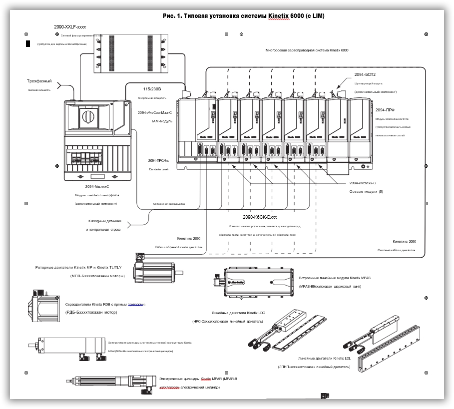
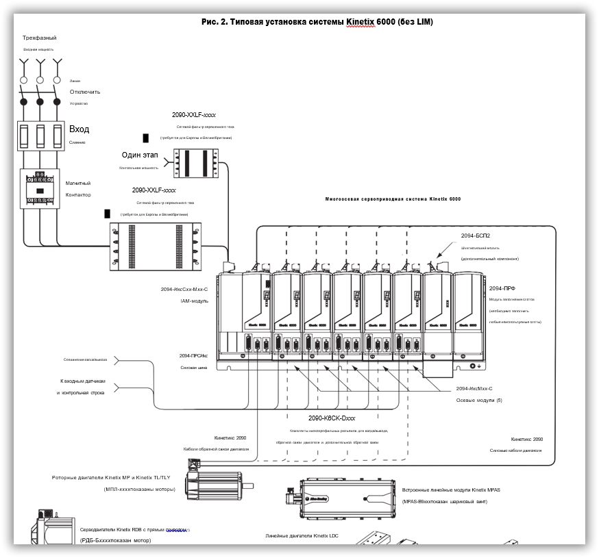
Типичные установки системы Kinetix 6000 включают конфигурации с трехфазным переменным током, с модулем линейного интерфейса (LIM) и без него, а также конфигурации с общей шиной постоянного тока.
Сетевой фильтр переменного тока
Комплекты низкопрофильных разъемов для ввода/вывода, обратной связи двигателя и дополнительной обратной связи
Типовая установка системы Kinetix 6000 (без LIM)
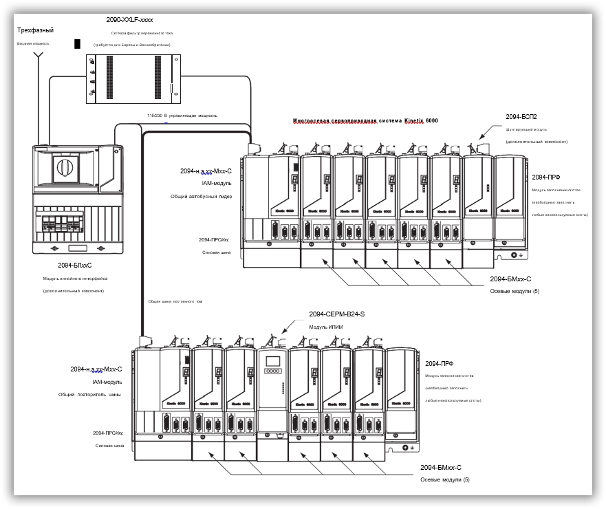
Эта конфигурация иллюстрирует систему Kinetix 6000M с интегрированным двигателем-приводом (IDM) с модулем интерфейса питания IDM (IPIM), установленным на шине питания Bulletin 2094. Модуль IPIM входит в состав оптоволоконного кабеля от привода к приводу вместе с осевыми модулями.
Рис. 4. Типовая установка системы общей шины постоянного тока (класс 400 В)
В приведенном выше примере ведущий модуль IAM подключен к ведомому модулю IAM через общую шину постоянного тока. Подчиняющая система также включает модуль интерфейса питания (IPIM) со встроенным двигателем-приводом (IDM) Kinetix 6000M, который поддерживает до 16 блоков IDM.
При планировании компоновки панели необходимо рассчитать общую емкость шины вашей системы с общей шиной постоянного тока, чтобы убедиться, что размер ведущего модуля IAM достаточен для предварительной зарядки всей системы. Чтобы получить больше информации.
|
|
ВАЖНЫЙ Если общая емкость шины вашей системы превышает рейтинг предварительной зарядки ведущего модуля IAM и подается входная мощность, семисегментный индикатор состояния модуля IAM отображает код ошибки E90 (ошибка тайм-аута предварительной зарядки).
Чтобы исправить это условие, вы должны заменить ведущий модуль IAM на модуль большего размера или уменьшить общую емкость шины, удалив модуль IPIM или модули AM.
Сервопреобразователи Kinetix 6000 – это высокотехнологичные устройства, которые позволяют управлять двигателями любых типов и классов. Этот продукт обладает уникальными техническими характеристиками, которые делают его незаменимым в реализации множества промышленных задач.
Основные преимущества сервопреобразователей Kinetix 6000:
— Благодаря своему высокому быстродействию Kinetix 6000 обеспечивает великолепную точность в работе двигателя, что позволяет добиваться наилучших результатов при решении любых задач.
— Гибкость – это еще одно преимущество, которым обладают сервопреобразователи Kinetix 6000. Вы можете изменять частоту вращения двигателя в зависимости от требований задачи.
— Простая установка и настройка. Никаких сложных процедур и настроек – все сделано таким образом, чтобы использование было легким и комфортным.
— Длительный срок службы. Высокий уровень надежности сервопреобразователей Kinetix 6000 гарантирует долговечность и безотказность продукта.
— Гибкая программируемость. Благодаря этому сервопреобразователю вы можете реализовывать задачи как на языке программирования, так и без него.
Технические характеристики сервопреобразователей Kinetix 6000:
— Широкий диапазон рабочих токов – до 27,1 А.
— Высокая частота вращения двигателя – до 7000 об./мин.
— Подключение по интерфейсам RS232, RS485, Ethernet/IP.
— Встроенный интерфейс для прямой связи с контроллерами Allen Bradley/Logix.
— Питание от 220 В до 240 В.
Сервопреобразователь Kinetix 6000 может использоваться с различными типами двигателей. Это могут быть моторы:
— Шаговые
— Постоянного тока
— Синхронные
— Асинхронные
Сервопреобразователи Kinetix 6000 – идеальный выбор для энергоэффективной автоматизации производственных задач различного уровня сложности. С помощью этой технологии вы сможете существенно увеличить производительность и точность работы оборудования, снизить затраты на обслуживание и техническое обслуживание, а также значительно повысить уровень безопасности производства.
Отметим также, что данное оборудование имеет широкий разброс цен и подходит как для крупных производств, так и для небольших предприятий. Используйте сервопреобразователи Kinetix 6000, и ваше производство заработает на максимальных оборотах!
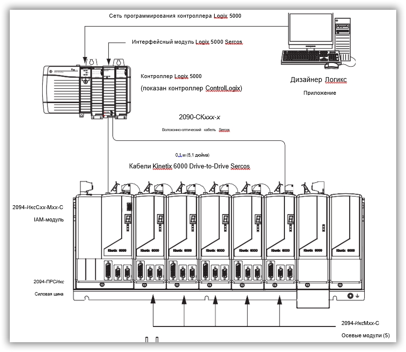
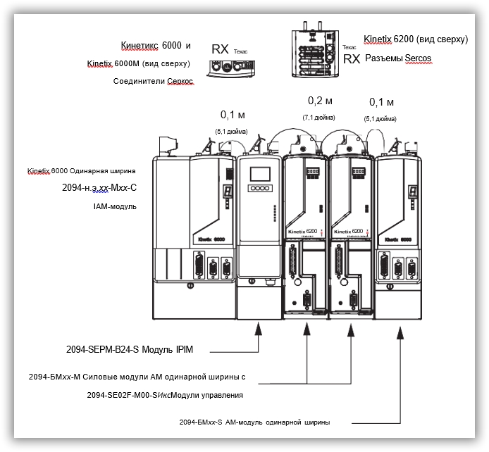
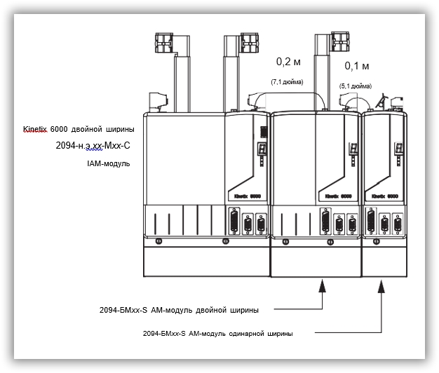
В этом примере показаны кабели Sercos между приводами и каталожные номера, когда модули приводов Kinetix 6000, Kinetix 6000M и Kinetix 6200 установлены на одной шине питания.
Модули управления Kinetix 6200 используют интерфейс Sercos для настройки модуля Logix 5000 и сеть EtherNet/IP для диагностики и настройки функций безопасности. Кабель Ethernet подключается к каждому модулю управления во время настройки безопасности
Стандартная связь Kinetix 6000 и Kinetix 6200 (Sercos)
Оборудование Allen-Bradley — это один из лидеров в производстве и поставке автоматического оборудования для промышленности. Компания Allen-Bradley была основана в 1903 году, и в настоящее время входит в состав корпорации Rockwell Automation. Она является мировым лидером в области проектирования, производства и технического обслуживания промышленного оборудования для контроля, управления и защиты.
Allen-Bradley предлагает широкий спектр продукции, включая контроллеры, программное обеспечение, сервоприводы, концевые выключатели, реле, считыватели кодов, сигнализаторы, средства связи и датчики. Компания сосредоточена на инновационном подходе к разработке оборудования, используя передовые технологии для улучшения функциональности и надежности своих продуктов.
Одним из самых популярных продуктов Allen-Bradley является их линия контроллеров. Эти контроллеры используются в широком спектре промышленных приложений, включая производство, логистику, эксплуатацию, энергетику, пищевую и фармацевтическую промышленность. Они обеспечивают надежный контроль и управление быстро изменяющимися процессами, улучшая эффективность производства и повышая качество продукции.
Allen-Bradley также предлагает широкий спектр сервоприводов, которые используются для управления давлением, преобразования движения, позиционирования и скорости. Сервоприводы обеспечивают точное и быстрое управление движениями, позволяя производственным предприятиям увеличить эффективность и точность производства.
Концевые выключатели, реле и счетчики Allen-Bradley также являются популярными продуктами, используемыми в различных промышленных приложениях. Они обеспечивают точное и надежное управление и контроль процессов, уменьшая количество ошибок и повышая качество продукции.
Allen-Bradley также предлагает широкий спектр программного обеспечения, которое позволяет пользователям легко управлять и мониторить производственные процессы. Они обеспечивают быстрый доступ к данным и представляют их в удобном для анализа и понимания формате. Это позволяет пользователям быстро обнаруживать проблемы и решать их, уменьшая время простоя и увеличивая производительность.
Существуют множество преимуществ использования оборудования Allen-Bradley для автоматизации производственных процессов. Одно из основных преимуществ заключается в том, что оборудование Allen-Bradley обеспечивает высокую надежность и точность управления процессами, что позволяет предприятиям повысить эффективность производства и улучшить качество продукции.
Кроме того, оборудование Allen-Bradley обеспечивает быстрый и легкий доступ к данным, что помогает пользователям быстро и точно анализировать условия производства и принимать наиболее эффективные решения. Как результат, пользователи смогут достигать максимальной производительности и экономической точности на своих предприятиях.
В целом, оборудование Allen-Bradley является ведущим на рынке промышленной автоматизации благодаря своей инновационности, надежности и точности управления процессами. Это позволяет предприятиям достигать максимальной эффективности производства и повышения качества продукции.
Сервопреобразователи Kinetix 6000 от компании Allen-Bradley имеют следующие технические характеристики:
— Номинальное входное напряжение: 200…460 В переменного тока
— Номинальный выходной ток: от 1,5 до 60 А
— Мощность: от 0,75 до 37 кВт
— Частота выходного напряжения: до 4 кГц
— Режим управления: скоростной, тяговый, позиционный
— Интерфейсы связи: EtherNet/IP, ControlNet, DeviceNet
— Встроенная защита от короткого замыкания, перегрузки и перегрева
— Размеры (ШхВхГ): от 170x182x233 до 720x692x362 мм
— Вес: от 1,2 до 64 кг
— Рабочая температура: от 0 до 40°C
Кроме того, сервопреобразователи Kinetix 6000 поддерживают разные типы моторов (ROT, LINE и PM) и могут использоваться в различных отраслях промышленности, в том числе в автомобильной, пищевой, фармацевтической и других отраслях.
Сервопреобразователи Kinetix 6000 – надежные и производительные устройства для управления двигателями в различных промышленных задачах. Эти сервопреобразователи обладают повышенной точностью, динамикой и возможностью настройки, что позволяет достигать высокой производительности на производстве.
Одним из главных преимуществ Kinetix 6000 является возможность максимальной настройки под конкретные требования задачи. Высокая точность управления двигателями позволяет использовать эти устройства в самых различных отраслях промышленности – машиностроение, робототехника, пищевая промышленность и многие другие.
Кроме того, сервопреобразователи Kinetix 6000 обладают высокой энергоэффективностью. Это означает, что они потребляют меньше электроэнергии, что позволяет снизить операционные расходы на производстве. Это особенно важно для тех, кто заботится о бережливости ресурсов, экологии и экономике предприятия.
Каждый сервопреобразователь Kinetix 6000 имеет свой собственный уникальный дизайн, который позволяет ему легко интегрироваться в существующее оборудование. Высокая гибкость устройства, возможность настройки и быстрое реагирование на изменения окружающей среды, позволяют использовать Kinetix 6000 в самых разных условиях и при любых требованиях к точности и производительности.
Если вы ищете надежное, производительное и гибкое устройство для управления двигателями, то сервопреобразователь Kinetix 6000 – это именно то, что вам нужно. Созданный с использованием передовых технологий и инженерных решений, этот сервопреобразователь обеспечивает высокие эксплуатационные характеристики и энергоэффективность, а также гарантирует максимальную производительность на производстве.
Rockwell Automation Publication 2094-UM001H-EN-P — June 2013
165
Troubleshooting the Kinetix 6000 Drive System
Chapter 7
Kinetix 6000 Drive System Error Codes
The following list of problematic symptoms (no error code shown) and faults
with assigned error codes is designed to help you resolve anomalies.
When a fault is detected, the seven-segment status indicator displays an E
followed by the flashing of the two-digit error code, one digit at a time. This is
repeated until the error code is cleared.
Table 99 — Seven-segment Status Indicator Error Codes
Error
Code
Fault Message — Logix
Designer (HIM)
Anomaly or Symptom
Potential Cause
Possible Resolution
No Error Code Displayed
Power (PWR) indicator not ON
No AC power or auxiliary logic power.
Verify AC control power is applied to the
Kinetix 6000 system.
Internal power supply malfunction.
Call your Rockwell Automation sales representative
to return module for repair.
Motor jumps when first
enabled
Motor wiring error.
• Check motor wiring.
• Run Hookup test in the Logix Designer
application.
Incorrect motor chosen.
Verify the proper motor is selected.
Digital I/O not working
correctly
I/O power supply disconnected.
Verify connections and I/O power source.
E00
BusUndervoltage Fault
(Blown fuse)
A blown fuse was detected on
the inverter PCB
Blown fuse.
Call your Rockwell Automation sales representative
to return module for repair.
E04
MotorOvertemp Fault
(Motor Overtemp)
Motor thermal switch tripped
• High motor ambient temperature
and/or
• Excessive current
• Operate within (not above) the continuous
torque rating for the ambient temperature 40 °C
(104 °F) maximum.
• Lower ambient temperature, increase motor
cooling.
Motor wiring error.
Check motor wiring at MF connector on the IAM/AM
module.
Incorrect motor selection.
Verify the proper motor has been selected.
E05
DriveOvercurrent Fault
(Power Fault)
Self-protection of the
Intelligent Power Module
(IPM) is indicating a major
power related fault condition.
Motor cables shorted.
Verify continuity of motor power cable and
connector.
Motor winding shorted internally.
Disconnect motor power cables from the motor. If
the motor is difficult to turn by hand, consider
replacing the motor.
Kinetix 6000 drive temperature too high.
• Check for clogged vents or defective fan.
• Make sure cooling is not restricted by insufficient
space around the unit.
Operation above continuous power rating and/or
product environmental ratings.
• Verify ambient temperature is not too high.
• Operate within the continuous power rating.
• Reduce acceleration rates.
Kinetix 6000 drive has a short circuit, overcurrent,
or failed component.
Remove all power and motor connections, and
preform a continuity check from the DC bus to the U,
V, and W motor outputs. If a continuity exists, check
for wire fibers between terminals, or send drive in
for repair.
E06
HardOvertravel Fault
(+/- Hard Overtravel)
Axis moved beyond the
physical travel limits in the
positive/negative direction.
Dedicated overtravel input is inactive.
• Check wiring.
• Verify motion profile.
• Verify axis configuration in software.
E07
MotFeedbackFault
(Motor Feedback Loss)
The feedback wiring is open, shorted, or missing.
• Check motor encoder wiring.
• Run Hookup test in the Logix Designer
application.
(Ocr-Read Summary of Contents of some pages of the Rockwell Automation Allen-Bradley Kinetix 6000 Document (Main Content), UPD: 07 March 2023)
-
38, 38 Rockwell Automation Publication 2094-UM001D-EN-P — May 2010 Chapter 2 Planning the Kinetix 6000 Drive System Installation Observe these guidelines when a 2094-AL09 or 2094-BL02 LIM module is used in the Bulletin 2094 system and mounted left of the IAM module: • The clean zone (C) is to the right and beneath the Bulletin 2094 system (gray wireway). • The dirty zone (D) is to the left and above the Bulletin 2094 system, an…
-
17, Rockwell Automation Publication 2094-UM001D-EN-P — May 2010 17 Start Chapter 1 Figure 3 — Typical DC Common Bus System Installation In the example above, the leader IAM module is connected to the follower IAM module via the DC common-bus. When planning your panel layout, you must calculate the total bus capacitance of your DC common-bus system to be sure that the leader IAM module is sized sufficiently to pre-charge the entire system. …
-
32, Rockwell Automation Allen-Bradley Kinetix 6000 32 Rockwell Automation Publication 2094-UM001D-EN-P — May 2010 Chapter 2 Planning the Kinetix 6000 Drive System Installation These illustrations show details of recommended bonding practices for painted panels, enclosures, and mounting brackets. Figure 7 — Recommended Bonding Practices for Painted Panels Stud-mounting the Subpanel to the Enclosure Back Wall Stud-mounting a Ground Bus or Chassis to the Subpanel Subpanel Welded Stud Scrape Paint Flat Washe…
-
20, 20 Rockwell Automation Publication 2094-UM001D-EN-P — May 2010 Chapter 1 Start Drive Component Compatibility The 2094-BCxx-Mxx-M and 2094-BMxx-M power modules contain the same power structure as the 2094-BCxx-Mxx-S and 2094-BMxx-S drive modules. Because of this, the 2094-BSP2 shunt module, 2094-PRF slot-filler module, and 2094-PRSx power rails are supported by both drive families. In addition, 2094-BMxx-M AM power mo…
-
208, 208 Rockwell Automation Publication 2094-UM001D-EN-P — May 2010 Appendix B Interconnect Diagrams Figure 92 8720MC-RPS Leader Drive with Single Follower IAM Module CONT EN- CONT EN+ W V U DC- DC+ L3 L2 L1 CTRL 2 CTRL 1 1 2 1 2 3 4 5 6 1 2 6 5 4 3 2 1 4 3 2 1 MBRK — MBRK + COM PWR DBRK — DBRK + N.C. N.C. N.C. E/N L1 L2 L3 G R S T TB1 CR1* CR1* L1 AUX L2 AUX L3 AUX PR1 PR2 PR3 MC1 MC2 TB2 R1 S1 T1 MC TB1 DC- DC+ N P TB3 COM RDY +24V DC PWR…
-
47, Rockwell Automation Allen-Bradley Kinetix 6000 Rockwell Automation Publication 2094-UM001D-EN-P — May 2010 47 Chapter 3 Mounting the Kinetix 6000 Drive System Introduction This chapter provides the system installation procedures for mounting your Kinetix 6000 drive components on the Bulletin 2094 power rail. This procedure assumes you have prepared your panel, mounted your Bulletin 2094 power rail, and understand how to bond your system. For installation instructions …
-
44, 44 Rockwell Automation Publication 2094-UM001D-EN-P — May 2010 Chapter 2 Planning the Kinetix 6000 Drive System Installation External Shunt Modules Observe these guidelines when mounting your external shunt module outside the enclosure: • Mount circuit components and wiring in the very dirty zone or in an external shielded enclosure. Run shunt power and fan wiring inside metal conduit to minimize the effects of EMI and RFI. …
-
62, 62 Rockwell Automation Publication 2094-UM001D-EN-P — May 2010 Chapter 4 Kinetix 6000 Connector Data IAM and AM Motor Power and Brake Connector Pinout Table 26 — Motor Power Connector Table 27 — Motor Brake/Resistive Brake Connector MP Pin Description Signal 4 Chassis ground 3 Three-phase motor power W 2V 1U IMPORTANT Combined motor-power cable length for all axes on the same DC bus must not exceed 240 m (787 ft) with 460V systems or 160 m (525 ft) with 230V systems. Drive-to-m…
-
165, Rockwell Automation Publication 2094-UM001D-EN-P — May 2010 165 Troubleshooting the Kinetix 6000 Drive System Chapter 7 Shunt Module Status Indicators Each of the shunt module status indicators provide specific troubleshooting information. Table 88 — General Shunt Module Troubleshooting Module Status Under These Conditions Shunt Fault is latched. Until fault condition is corrected and cleared. Fault is cleared.…
-
162, 162 Rockwell Automation Publication 2094-UM001D-EN-P — May 2010 Chapter 7 Troubleshooting the Kinetix 6000 Drive System E66 No Fault Message (condition indicated by on-screen message) (Atune Flt) Autotune procedure failed Motor or feedback device malfunction. • Check motor power/feedback wiring. • Refer to on-screen message for resolution. • Perform Hookup in RSLogix 5000 software. • Consult RSLogix 5000 help screen. E67 DriveHardFault (Ta…
-
197, Rockwell Automation Publication 2094-UM001D-EN-P — May 2010 197 Specifications and Dimensions Appendix A Figure 85 — AM Module Dimensions 2094-AMP5-x, 2094-AM01-x, and 2094-AM02-x (230V) 2094-BMP5-x, 2094-BM01-x, and 2094-BM02-x (460V) The AM module is shown mounted to the power rail. Table 117 — AM Module Dimensions 20 (0.8) 8.9 (0.35) 70 (2.76) A B D E F 62 (2.45) Dimensions are in millimeters (inc…
-
37, Rockwell Automation Publication 2094-UM001D-EN-P — May 2010 37 Planning the Kinetix 6000 Drive System Installation Chapter 2 Keep the DC common-bus cable (very dirty) segregated from all other cables (not in a wireway) when the 2094-ALxxS, 2094-BLxxS, or 2094-XL75S-Cx LIM module is used in a DC common-bus configuration and the follower IAM module is mounted below the leader IAM module. Figure 12 — Noise Zones (DC common bus) (1) If drive system I/…
-
31, Rockwell Automation Publication 2094-UM001D-EN-P — May 2010 31 Planning the Kinetix 6000 Drive System Installation Chapter 2 Electrical Noise Reduction This section outlines best practices that minimize the possibility of noise-related failures as they apply specifically to Kinetix 6000 system installations. For more information on the concept of high-frequency (HF) bonding, the ground plane principle, and electrical noise reduction, refer to the System Design for Control of Elect…
-
152, 152 Rockwell Automation Publication 2094-UM001D-EN-P — May 2010 Chapter 6 Configure and Start Up the Kinetix 6000 Drive System The Online Command — Apply Tune dialog box opens. When the test completes, the Command Status changes from Executing to Command Complete. 11. Click OK. 12. Determine if your test completed successfully. 13. Repeat Test and Tune the Axes for each axis. If Then Your test …
-
100, Rockwell Automation Allen-Bradley Kinetix 6000 100 Rockwell Automation Publication 2094-UM001D-EN-P — May 2010 Chapter 5 Connecting the Kinetix 6000 Drive System Pigtail Terminations TL-Series motors have a short pigtail cable that connects to the motor, but is not shielded. The preferred method for grounding the TL-Series power cable on the motor side is to expose a section of the cable shield and clamp it directly to the machine frame. The motor power cable also has a 150 mm (6.0 in.) shield termination wire with a ring …
-
30, 30 Rockwell Automation Publication 2094-UM001D-EN-P — May 2010 Chapter 2 Planning the Kinetix 6000 Drive System Installation Minimum Clearance Requirements This section provides information to assist you in sizing your cabinet and positioning your Bulletin 2094 system components. Figure 6 — Minimum Clearance Requirements (1) The power rail (slim), catalog number 2094-PRSx, extends left and right of the first and last module 5.0 mm (0.20 in.). The power rail, catalog number…
-
175, Rockwell Automation Publication 2094-UM001D-EN-P — May 2010 175 Removing and Replacing the Kinetix 6000 Drive Modules Chapter 8 7. Lift the bracket out of the power rail slot and remove the module from the power rail. Replace Kinetix 6000 Drive Modules Follow these steps to replace drives from the Bulletin 2094 power rail. Follow these steps to replace the drive modules. 1. Determine your drive module rep…
-
222, 222 Rockwell Automation Publication 2094-UM001D-EN-P — May 2010 Appendix B Interconnect Diagrams Figure 107 AM Module with LDC-Series or LDL-Series Linear Motors with Cable Connectors C B A W V U 4 3 2 1 GREEN/YELLOW BLUE BLACK BROWN GND SHIELD W V U 1 4 2 5 3 6 8 7 (AM-) (AM+) (BM-) (BM+) IM- IM+ ECOM +5VDC BLUE WHT/BLUE WHT/GREEN GREEN WHT/GRAY GRAY WHT/BLACK BLACK WHT/RED RED TS+ TS- S1 S2 S3 YELLOW WHT/YE…
-
264, 264 Rockwell Automation Publication 2094-UM001D-EN-P — May 2010 Appendix F RBM Module Interconnect Diagrams This example diagram shows 2094-xCxx-Mxx and 2094-xMxx drives (without safe off) and 2094-AL09 and 2094-BL02 LIM modules wired with the Bulletin 2090 RBM module. Figure 117 — RBM Wiring Example, Category 2 Configuration per EN954-1 T2 T1 K 4 3 2 1 4 3 2 1 D C B A IO_PWR BRKTMP0 CONT EN- CONT EN+ W V U L3 L2 L1 DC- DC+ L3 L2 L1 CTRL 2 CTRL 1 L…
-
73, Rockwell Automation Allen-Bradley Kinetix 6000 Rockwell Automation Publication 2094-UM001D-EN-P — May 2010 73 Kinetix 6000 Connector Data Chapter 4 Feedback Specifications The IAM and AM modules can accept motor and auxiliary feedback signals from these types of encoders: • Stegmann Hiperface • TTL or Sine/Cosine with index pulse and Hall commutation • Resolver Transmitter TR = 0.25 (motor feedback only) Motor feedback from Heidenhain EnDat high-resolution encoders is also accepted, but only wh…


