-
Contents
-
Table of Contents
-
Bookmarks
Quick Links
OPERATOR’S MANUAL
AGC 150
Generators, Mains and BTB
4189341312A
Related Manuals for Deif AGC 150
Summary of Contents for Deif AGC 150
-
Page 1
OPERATOR’S MANUAL AGC 150 Generators, Mains and BTB 4189341312A… -
Page 2: Table Of Contents
1.4 Legal information ……………………………………..2. Getting started 2.1 About controller operation ………………………………….2.1.1 Display settings ……………………………………. 3. About the AGC 150 Generator 3.1 Display, buttons and LEDs ………………………………….3.2 Mimic function ……………………………………… 3.3 Running modes ……………………………………..3.4 Exhaust after-treatment (Tier 4/Stage V) …………………………….
-
Page 3: Introduction
This document gives the necessary information to operate the controller. CAUTION Installation errors Read this document before working with the AGC 150 controller. Failure to do this may result in human injury or damage to the equipment. Intended users of the operator’s manual The operator’s manual is for the operator that uses the controller regularly.
-
Page 4: Warnings And Safety
Legal information Third party equipment DEIF takes no responsibility for the installation or operation of any third party equipment, including the genset. Contact the genset company if you have any doubt about how to install or operate the genset. Warranty…
-
Page 5: Getting Started
About controller operation The AGC 150 Generator controller contains all the functions needed to protect and control a genset, and the genset breaker. If you do not use power management, the controller can also protect and control the mains breaker.
-
Page 6: About The Agc 150 Generator
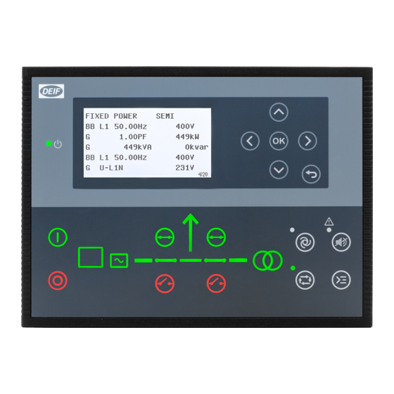
3. About the AGC 150 Generator Display, buttons and LEDs Name Function Green: The controller power is ON. Power OFF: The controller power is OFF. Resolution: 240 x 128 px. Display screen Viewing area: 88.50 x 51.40 mm. Six lines, each with 25 characters.
-
Page 7: Mimic Function
Name Function Green flashing: Synchronising or deloading. Red: Breaker failure. Green: Generator voltage and frequency are OK. The controller can synchronise and close the breaker. Generator Green flashing: The generator voltage and frequency are OK, but the V&Hz OK timer is still running. The controller cannot close the breaker.
-
Page 8: Running Modes
Running modes The AGC 150 Generator controller has four running modes, and a test mode. To configure the running mode push the Shortcut button and select Running Modes. Configure the test mode in Settings > Power set points > Test. To run the test push the Shortcut button and select Start Test.
-
Page 9
AGC 150 Tier 4/Stage V screen ISLAND SEMI DEF level: 32.0% 1/20 Referent Symbol Description Engine emission system failure Shows an emission failure or malfunction. Diesel Particle Filter (DPF) Shows that a regeneration is needed. Application mode Diesel Particle Filter (DPF) Inhibit Shows that regeneration is inhibited. -
Page 10
Referent Symbol Description Engine interface status Shows an engine shutdown. LIMIT lamp Only for MTU engines. Diesel Exhaust Fluid (DEF) Shows the fluid tank level is low. Diesel Exhaust Fluid (DEF) % level Shows the level (%) of the Diesel Exhaust Fluid. NOTE Grey symbols show that communication is available for the referent. -
Page 11: About The Agc 150 Mains
4. About the AGC 150 Mains Display, buttons and LEDs Name Function Green: The controller power is ON. Power OFF: The controller power is OFF. Resolution: 240 x 128 px. Display screen Viewing area: 88.50 x 51.40 mm. Six lines, each with 25 characters.
-
Page 12: Mimic Function
The controller is de-loading Running modes The AGC 150 Mains controller has three running modes, and a test mode. Push the Shortcut button and select Running Modes to configure the mode. Configure the test mode in Settings > Power set points > Test. To run the test push the Shortcut button and select Start Test.
-
Page 13: About The Agc 150 Btb
5. About the AGC 150 BTB Display, buttons and LEDs Name Function Green: The controller power is ON. Power OFF: The controller power is OFF. Resolution: 240 x 128 px. Display screen Viewing area: 88.50 x 51.40 mm. Six lines, each with 25 characters.
-
Page 14: Mimic Function
• The controller is synchronising • The controller is de-loading Running modes The AGC 150 BTB controller has three running modes. To configure the running mode push the Shortcut button and select Running Modes. Mode Description The controller automatically joins and splits the busbar. The operator cannot start a sequence manually. The AUTO controllers use the power management configuration to automatically select the power management action.
-
Page 15: Menus
6. Menus Menu structure The AGC 150 has two menu systems, which can be used without password entry: • The View menu system: Shows the operating status and values. The system has 20 configurable windows, that can be entered with the arrow buttons.
-
Page 16: Menu Numbers
6.2.1 Menu numbers Each parameter has a menu number. You can find the number in the upper right corner on the display screen. You can also find the menu number with the utility software: 1. Select Parameters from the vertical toolbar on the left. 2.
-
Page 17: Display Views
2. Values and information 3. Page number, power management priority, power management ID and engine DEF level. The view menu has 20 different display views. Use the buttons to select a view. AGC 150 Generator example Push AGC 150 Mains example Push…
-
Page 18
AGC 150 Generator Line View 1 View 2 View 3 View 4 View 5 U-Supply 0.0V BB L1 0.0Hz 0V BB L1 0.0Hz 0V G U-L1L2 0V G 0.00PF 0kW G L1 0.0Hz 0V Synchroniser G 0.00PF 0kW G U-L2L3 0V G 0kVA 0kvar G 0.00PF 0kW… -
Page 19: Display Text
M 0.00PF 0kW Multi Input 23 0 MB operations BB Angle L1L2 0deg M 0 0 0A Energy Total 0kWh TB Operations BB Angle L2L3 0deg AGC 150 BTB Line View 1 View 2 View 3 View 4 View 5 U-Supply 0.0V BB L1 0.0Hz 0V…
-
Page 20: Status Texts
3. Select the display line you want to change. 4. In the pop-up window, select the text you want and click OK. Display text You can select five of the display texts for each display view. Status texts Status text Condition ACCESS LOCK The configurable input is activated, and the operator tries to activate one of the blocked keys.
-
Page 21
Status text Condition Power management: Broadcast one of the four applications from one controller to the other BROADCASTING APPL. # controllers in the power management system, through the CAN line. BROADCAST COMPLETED Power management: Correct broadcast of an application. BTB power management: External equipment has tripped the breaker, and this is logged in the BTB TRIP EXTERNALLY event log. -
Page 22
Status text Condition The frequency or voltage measurement is outside the limits. The timer shown is the mains failure MAINS FAILURE IN ###s delay. MAINS f OK DEL ####s Mains frequency is OK after a mains failure. The timer shown is the mains OK delay. MAINS P EXPORT AUTO The mains controller is in auto mode and ready to respond. -
Page 23: Service View
Status text Condition STOP DG(s) IN ###s The stop genset set point has been exceeded. The genset stops when the timer expires. SYNCHRONISING BTB XX Generator power management: BTB XX is synchronising. SYNCHRONISING MB XX Generator power management: MB XX is synchronising. SYNCHRONISING TB XX Generator power management: TB XX is synchronising.
-
Page 24: Alarm Handling And Log List
7. Alarm handling and log list Alarm handling If the function Alarm Jump is on, the controller automatically shows the alarm list on the display screen when an alarm occurs. Service View > Display > Alarm Jump Parameter Text Range Default 9157 Alarm Jump…
-
Page 25: Logs Menu
CAUTION Caution If an alarm is blocking a genset in AUTO mode from starting, the genset automatically starts if the condition that triggered the alarm has gone and the alarm has been acknowledged. Logs menu These are the log sub-menus: 1.
- Sobre
![]()
-
Home
-
Documentation
- AGC 150 Stand-alone
Go to product page
About
Manuals
Installation Instructions
Reference
Other Technical Documentation
Também somos bem sociáveis
- Über uns
![]()
-
Home
-
Documentation
- AGC 150 Remote display
Go to product page
About
Manuals
Installation Instructions
Reference
Other Technical Documentation
Wir sind auch in sozialen Netzwerken aktiv
Types of Manuals:
The main types of Deif AGC 150 instructions:
- User guide — rules of useing and characteristics
- Service manual — repair, diagnostics, maintenance
- Operation manual — description of the main functions of equipment
Controller, Marine Equipment, Measuring Instruments Instructions by Deif:
-
Panasonic PAW-PACR3
1Instructions for the Electrical Installer (PAW-PACR3)For your safety Read the following instructions carefully, and carry out secure installation and electrical work. The precautions given in this manual consist of specific “Warnings” and “Cautions”. They provide important safety-related information. Be …
PAW-PACR3 Controller, 17
-
Dynojet Power commander v
15-013 www.powercommander.com 2010-2011 Harley Davidson Dyna PCV — 1PARTS LIST1 Power Commander1 USB Cable1 CD-ROM1 Installation Guide2 Power Commander Decals2 Dynojet Decals2 Velcro1 Alcohol swab2 O2 eliminatorsYOU CAN ALSO DOWNLOAD THE POWER COMMANDER SOFTWARE AND LATEST MAPS FROM OUR WEB SITE AT:www.power …
Power commander v Automobile Accessories, 6
-
Dynojet Power commander v
2007-2008 Yamaha R1 — PCV — 122-036 www.powercommander.comInstallation InstructionsPLEASE READ ALL DIRECTIONS BEFORE STARTING INSTALLATIONTHE IGNITION MUST BE TURNED OFF BEFORE INSTALLATION!THE LATEST POWER COMMANDER SOFTWARE AND MAP FILES CAN BE DOWNLOADED FROM OUR WEB SITE AT:www.powercommander.com2191 Mendenhal …
Power commander v Automobile Accessories, 4
-
Oxford Instruments Omicron NanoScience MercuryiTC
Operator’s Manual MercuryiTC ©2014 Oxford Instruments Omicron NanoScienceOperator’s Manual Oxford Instruments NanoScience Issue 05 / Feb 2015 / Original Instructions MercuryiTC Cryogenic environment controllerIssue 05 / Feb 2015 / UMC0071Omicron NanoScience. All rights reserved. Oxford Instruments OmicronNano …
MercuryiTC Controller, 174
-
SCHUNK UWG Series
1Montage- und Betriebsanleitung fürWinkelgreifer Type UWGOperating manual forAngular Gripper Type UWGDruck-Nr.: 03 / 0008 / D-GB / 09.00 H / 002-Finger-WinkelgreiferType: UWG2-Finger-Angular GripperType: UWGSehr geehrter Kunde,wir freuen uns, dass Sie sich für ein SCHUNK-Produkt entschieden haben.Bitte beachten S …
UWG Series Controller, 11
-
Siemens SINUMERIK 828D Turning
SINUMERIK SINUMERIK 828D Fundamentals Programming ManualValid for: CNC system software Version 4.3 07/2010 6FC5398-1BP40-0BA0 Preface Fundamental Geometrical Principles 1Fundamental Principles of NC Programming 2Creating an NC program 3Tool change 4Tool offsets 5Spindle motion 6Feed control 7Geometry settin …
SINUMERIK 828D Turning Control Unit, 610
-
Laversab 6300
MODEL 6300 Rev. E5 USER’S MANUAL LAVERSAB INC., 505 GILLINGHAM LANE SUGAR LAND TX 77478. (281) 325-8300 FAX: (281) 325-8399 Email: [email protected] Document Number : 9033 REV.E5 Date: Februar …
6300 Controller, 72
-
Eaton Digitrip RMS
TABLE OF CONTENTS PAGE1.0 Supplementary Information…………………………….. 22.0 Digitrip RMS and Digitrip OPTIM Trip Units ………. 23.0 Rating Plugs…………………………………………………. 33.0.1 Digitrip RMS Plugs for 510, 610, 810,910…………. 3 …
Digitrip RMS Controller, 24
(Ocr-Read Summary of Contents of some pages of the Deif AGC 150 Document (Main Content), UPD: 17 March 2023)
-
19, Deif AGC 150 Analogue tacho input (W) 19 20 21 22 23 24 25 26 27 28 29 30 31 32 Pos SCR Neg Charging alternator W B- 5.3 DC connections 5.3.1 Digital inputs 39 40 41 42 43 44 45 46 47 48 49 50 In In In In In In In In MB on MB off GB/TB on GB/TB off In order to be EN60255 compliant, when wiring is more than 10 m, a 4007 diode must be connected on each input. 5.3.2 Digital outputs 8 9 10 11 12 13 14 15 16 17 18 DC (+) Out Out Out Out Out O…
-
18, 19 20 21 22 23 24 25 26 27 28 29 30 31 32 Pos SCR Neg Tacho Analogue tacho input (NPN) 19 20 21 22 23 24 25 26 27 28 29 30 31 32 Pos SCR Neg Tacho + — Analogue tacho input (PNP) 19 20 21 22 23 24 25 26 27 28 29 30 31 32 Pos SCR Neg Tacho — INSTALLATION INSTRUCTIONS UK Page 18 of 22
… -
8, Materials Used for Ethernet cable Connecting the controller communication between controllers and/or external systems Cable ties Securing wiring and Ethernet cable 3.1.3 Mounting instructions The controller is designed for mounting in the panel front. Max. panel thickness: 4.5 mm (0.18 in). Panel cutout: • Width: 218.5 mm (8.60 in) • Height: 158.5 mm (6.24 in) • Tolerance: ± 0.3 mm (0.01 in) 1. Insert the controller in the pa…
-
10, Terminal Text Function Technical data 10 Out Configurable Max. 500 mA 11 Out Configurable Max. 500 mA 12 Out Configurable Max. 500 mA 13 Out Configurable Max. 500 mA 14 Out Configurable Max. 500 mA 15 MB on Configurable (application dependent) Max. 500 mA 16 MB off Configurable (application dependent) Max. 500 mA 17 GB/TB on Configurable (application dependent), also used for BTB ON Max. 500 mA 18 GB/TB off Configurable (application dependent), a…
-
21, 5.3.4 Power supply and start 1 2 3 4 5 6 7 DC (+) DC (-) Not used Emerg. stop Run coil Crank D+ Fuel M G D+ B+ F1 F2 Fuses: • F1: 2 A MCB, c-curve • F2: 6 A MCB, c-curve 5.4 Communication 5.4.1 CAN bus power management system 19 20 21 22 23 24 25 26 27 28 29 30 31 32 PMS Hi PMS Sh PMS Lo AGC 150 AGC 150 AGC 150 120120 PMS Hi PMS Sh PMS Lo PMS Hi PMS Sh PMS Lo Recommended cable: Belden 3105A or equivalent, 24 AWG (0.5 mm 2 ) twisted pair, shielded, imped…
-
12, Terminal Text Function Technical data 66 N B-side 67 L1 B-side 68 L2 B-side 69 L3 B-side Table 4.9 Plug 9: PC connection Description Function Technical data USB connection Service port USB B Table 4.10 Plug 9: Modbus connection Description Function Technical data RJ45 Modbus TCP/IP connection Ethernet INSTALLATION INSTRUCTIONS UK Page 12 of 22
… -
11, Table 4.5 Plug 5: Digital input Terminal Text Function Technical data 39 In Configurable Negative switching only, < 100 Ω 40 In Configurable Negative switching only, < 100 Ω 41 In Configurable Negative switching only, < 100 Ω 42 In Configurable Negative switching only, < 100 Ω 43 In Configurable Negative switching only, < 100 Ω 44 In Configurable Negative switching only, < 100 Ω 45 In Configurable…
-
5, • Restrict access to authorised persons. 1.3 Legal information 1.3.1 Third party equipment DEIF takes no responsibility for the installation or operation of any third party equipment, including the genset. Contact the genset company if you have any doubt about how to install or operate the genset. 1.3.2 Warranty CAUTION The AGC 150 controller is not to be opened by unauthorised personnel. If opened anyw…
-
1, Advanced Genset Controller AGC 150 Installation instructions DEIF A/S · Frisenborgvej 33 · DK-7800 Skive · Tel.: +45 9614 9614 · Fax: +45 9614 9615 · [email protected] · www.deif.com Document no.: 4189341185A
… -
13, Deif AGC 150 5. Wiring 5.1 Wiring overview 5.1.1 Wiring overview Figure 5.1 Typical wiring for genset 120120 + — + ‐ 120 s2 s1 P2 P1 s2s1 P2P1 s2s1 P2P1 + G ‐ ‐‐ P2P1 s2 s1 L1 L2 L3 N L1 L2 L3 N + F1 F2 F3 F4 F5 120 120 56 57 58 59 60 61 62 63 64 65 8 9 10 11 12 13 14 15 16 17 18 39 40 41 42 43 44 45 46 47 48 49 50 66 67 68 69 1 2 4 5 6 7 19 20 21 22 23 24 25 26 27 28 29 30 31 32 33 34 35 36 37 38 51 52 54 55 AC current CT-side DC out…
-
15, 3-phase application (4 wires) L1 L2 L3 N L1 L2 L3 N G 62 63 64 65 66 67 68 69 N L1 L2 L3 N L1 L2 L3 F5F4 3-phase application (3 wires) L1 L2 L3 L1 L2 L3 G 62 63 64 65 66 67 68 69 N L1 L2 L3 N L1 L2 L3 F5F4 When three-phase distribution systems are used, the neutral line (N) is only necessary if it is a three-phase + neutral system. If the distribution system is a three-phase system without neutral, then do not connect t…
-
17, Mains controller tie power 56 57 58 59 60 61 L1 L2 L3 N L4 (s1) L4 (s2) L1 L2 L3 N P2P1 s2 s1 5.2.3 Current transformer ground The current transformer ground connection must be made on the s2 connection. DANGER! Failure to ground the current transformer could lead to injury or death. 5.2.4 Voltage measurement fuses If the wires/cables must be protected with fuses, use max. 2 A slow blow fuses, dependent on the wires/cables to be protect…
-
14, Figure 5.3 Typical wiring for BTB s2s1 P2P1 s2s1 P2P1 ‐ ‐ P2P1 s2 s1 + — USBEternet + F1 + F3 F4 F5 120 120 120 ‐ BTB K2 K2 BTB feedback L1 L2 L3 N L1 L2 L3 N 56 57 58 59 60 61 62 63 64 65 8 9 10 11 12 13 14 15 16 17 18 39 40 41 42 43 44 45 46 47 48 49 50 66 67 68 69 1 2 4 5 6 7 19 20 21 22 23 24 25 26 27 28 29 30 31 32 33 34 35 36 37 38 51 52 54 55 AC current CT-side DC output (configurable) DC (+) GB/TB off GB/TB on MB off…
-
4, Deif AGC 150 Document Contents • Minimum wiring for the controller • Wiring communication Operator’s manual • Controller equipment (push-buttons and LEDs) • Operating the system • Alarms • Log Modbus tables • Modbus address list ◦ PLC addresses ◦ Corresponding controller functions • Descriptions for function codes, function groups 1.2 Warnings and safety 1.2.1 Safety during installation …
-
6, 2. Product description 2.1 General description 2.1.1 General description The AGC 150 is a controller containing all necessary functions for protection and control of a genset, a mains breaker, and a bus tie breaker. It can be used as a single controller for one genset, or a number of controllers can be connected in a complete power management system for synchronising projects, island applications or running parallel to mains. The …
-
22, Deif AGC 150 5.4.2 CAN bus engine communication Recommended cable: Belden 3105A or equivalent, 24 AWG (0.5 mm 2 ) twisted pair, shielded, impedance 120 Ω, <40 mΩ/m, min. 95 % shield coverage. In order to be EN60255 compliant, when wiring is more than 10 m, terminal 28 must be connected to GND. 5.4.3 Modbus 1 A 1 GND 1 B 2 A 2 GND 2 B 33 34 35 36 37 38 Scada/PLC/ … 120 Scada/PLC/ … 120 Recommended cable: Belden 3105A or equivalent, 24 AWG (0.5 mm 2 ) twisted pair, s…
-
20, 5.3.3 Breaker wiring Pulse breaker wiring 8 9 10 11 12 13 14 15 16 17 18 DC (+) MB on MB off GB/TB on GB/TB off — K1 K2 K3 K4 F3 L1 L2 L3 N L1 L2 L3 N G GB MB K1 K2 K3 K4 Continuous breaker wiring 8 9 10 11 12 13 14 15 16 17 18 DC (+) MB on MB off GB/TB on GB/TB off — K1 K3 F3 L1 L2 L3 N L1 L2 L3 N G GB MB K1K3 Fuse F3: 4 A MCB, b-curve INSTALLATION INSTRUCTIONS UK Page 20 of 22
…