-
Contents
-
Table of Contents
-
Troubleshooting
-
Bookmarks
Quick Links
A
D
T
—
H
C
4
5
0
0
A
D
T
—
H
C
4
5
0
0
Flame / Plasma Cutting Machine CNC System
User’s Manual
Adtech (Shenzhen) CNC Technology Co., Ltd.
Add: F/5, Bldg/27-29, Tianxia IC Industrial Park, Yiyuan Rd, Nanshan District, Shenzhen
Postal code: 518052
Tel: 0755-26722719 (20 lines)
Fax: 0755-26722718
E-mail: Adtech@21cn.com
http://www.adtechcn.com
Summary of Contents for Adtech ADT-HC4500
-
Page 1
Flame / Plasma Cutting Machine CNC System User’s Manual Adtech (Shenzhen) CNC Technology Co., Ltd. Add: F/5, Bldg/27-29, Tianxia IC Industrial Park, Yiyuan Rd, Nanshan District, Shenzhen Postal code: 518052 Tel: 0755-26722719 (20 lines) Fax: 0755-26722718 E-mail: Adtech@21cn.com http://www.adtechcn.com… -
Page 2
This manual doesn’t contain any assurance, stance or implication in any form. Adtech and the employees are not responsible for any direct or indirect data disclosure, profits loss or cause termination caused by this manual or any information about mentioned products in this manual. -
Page 3
ADT-HC4500 Flame/Plasma Cutting Machine CNC System Basic Manual Info Item No. First uploaded on Version No. Pages Compiled by Typeset by XT20110101 2010/03/07 A0101 Xiaodan Xiaodan Revision Date Version/Page Result Confirmed by — 2 -… -
Page 4
ADT-HC4500 Flame/Plasma Cutting Machine CNC System Precautions Transportation and storage The packaging boxes shouldn’t be stacked more than six layers Do not climb onto, stand on or put heavy objects on the packaging box Do not drag or convey the product with a cable connected to the product… -
Page 5: Table Of Contents
ADT-HC4500 Flame/Plasma Cutting Machine CNC System Contents Chapter I: Introduction ………………… — 7 — 1. Function …………………………- 7 — 2. Features …………………………- 7 — 3. Application environment ……………………… — 8 — Chapter II: Quick Guide ………………..- 9 — 1.
-
Page 6
ADT-HC4500 Flame/Plasma Cutting Machine CNC System 5. Diagnosis …………………………- 75 — 5.1 Submenu description ……………………- 75 — 6. Upgrade …………………………- 79 — 6.1 Submenu description ……………………- 79 — 6.2 Reset ………………………… — 80 — 6.3 Upgrading through USB disk ………………….- 83 — 6.4 Connecting to PC and upgrading ……………….. -
Page 7
ADT-HC4500 Flame/Plasma Cutting Machine CNC System 2. The cutting isn’t accurate ……………………- 122 — 3. The cutting quality of corners is low ………………… — 122 — 4. The cut square becomes rectangle ………………….- 122 — 5. The cut circle becomes ellipse ………………….. — 122 — 6. -
Page 8: Chapter I: Introduction
IC chip and multilayer PCB. The monitor is 7” color display, and uses SMT process. The hardware of this controller bases on the powerful R&D strength of Adtech for many years, and the software integrates features of many domestic and foreign manufacturers. This controller features high hardware stability, perfect and mature software performance.
-
Page 9: Application Environment
ADT-HC4500 Flame/Plasma Cutting Machine CNC System 14) Space running, board measuring, knife aligning, and backtracking 15) Slot compensation, backlash compensation for machine tools 16) Graphics display, real-time cutting track display 17) Integrate diagnosis function to help users eliminate machine failures quickly…
-
Page 10: Chapter Ii: Quick Guide
ADT-HC4500 Flame/Plasma Cutting Machine CNC System Chapter II: Quick Guide ADT-HC4500 flame/plasma CNC cutting system controls the flame or plasma torch for cutting on the machine tool. The system displays in progressive windows. In certain interface, you can press [F1] to [F6] to select a function, and press [ ] or [ ] to return to previous menu.
-
Page 11: Get Help Info
ADT-HC4500 Flame/Plasma Cutting Machine CNC System Press [F6] to enter system parameter reset, software update and help interface. 1. Get help info In most menus, you can press [INS] to get the help information; for example, press [F1] (Auto) in the main menu to enter the Auto interface, and then press [INS] to get the help info about the Auto interface.
-
Page 12: Graphics Library
ADT-HC4500 Flame/Plasma Cutting Machine CNC System 3. Graphics library To facilitate the processing, reduce the workload and increase system usability, the system embodies 35 common processing part graphics and one test graphics. In the main menu interface, press [F2] (Graphics library) to enter the graphics library interface, and select the corresponding graphics parts in the library to process.
-
Page 13: Importing Processing File
ADT-HC4500 Flame/Plasma Cutting Machine CNC System Current directory: Return / New / Copy Delete Return Fig. 2.4 Copy Processing Files Then, press [Y+][Y-] to select the processing file to copy, and press [F2] (Copy) or [OK] to copy; after copying, press any key to return to the main menu when the prompt pops up.
-
Page 14: Adjusting Cutting Speed
ADT-HC4500 Flame/Plasma Cutting Machine CNC System Return Import Delete / Copy / Copy all / Return Fig. 2.5 File Importing Interface In above interface, press [Y+][Y-] to select a processing file and then press [F2] or [OK] to confirm; the system enters processing code edit interface.
-
Page 15
ADT-HC4500 Flame/Plasma Cutting Machine CNC System Manual speed Processing speed Return / System / Speed / Adjust / Control / Precision / Store / Return 2.6.1 Speed Setting Interface Press [X+], [X-], [Y+], [Y-] to move the cursor to select, and press the number keys in the left to enter the value. -
Page 16: Adjusting Manual Speed
ADT-HC4500 Flame/Plasma Cutting Machine CNC System The processing speed depends on the “Processing speed limit” in Speed Setting interface and “Speed percentage” in Auto interface. Actual processing speed = Processing speed × Speed percentage in Auto interface Note: The speed percentage is adjusted with [F ]/[F ] on the panel or the [F] key.
-
Page 17: Controlling Corner Cutting Quality
ADT-HC4500 Flame/Plasma Cutting Machine CNC System Note: The speed percentage is adjusted with [F ]/[F ] on the panel or the [F] key. 8. Controlling corner cutting quality During flame cutting and plasma cutting, the speed should be controlled when cutting the corners. The acceleration/deceleration setting directly affects the quality of corner cutting, especially during the flame cutting, if the speed is too high, the flame may be off or can’t cut through the steel plate;…
-
Page 18
ADT-HC4500 Flame/Plasma Cutting Machine CNC System data are adjusted according to field cutting effect: Processing speed (mm/min) Start speed (mm/min) 100-200 200-500 500-700 700-800 800-1000 1000-1300 1600-2000 1000 2000-3000 1500 3000-4000 2000 Table 2.8.1 Acceleration: the average increment that the processing speed is added from start speed to top speed;… -
Page 19: Adjusting Preheating Time While Flame Cutting
ADT-HC4500 Flame/Plasma Cutting Machine CNC System 0.010000-0.011000 0.011000-0.012000 0.012000-0.013000 Table 2.8.2 9. Adjusting preheating time while flame cutting In the main menu interface, press [F4] (Parameter) [F4] (Control), and set the “Preheating delay” in the second line to desired time.
-
Page 20
ADT-HC4500 Flame/Plasma Cutting Machine CNC System Return 2.9.1 Control Interface While cutting in Auto interface, the system performs preheating before perforation. At this moment, the lower right of the interface shows the total preheating time and preheated time. In the bottom center, the system prompts: “To memorize and stop preheating, press [G];… -
Page 21: Power Failure Treatment
ADT-HC4500 Flame/Plasma Cutting Machine CNC System Prompt: Working state: Running Flame Return / Demonstrate / Manual / Back / Process / Return reference / Break point / Return 2.9.2 Auto Interface Preheating 10. Power failure treatment To avoid material waste caused by sudden power failure, the system integrates power failure protection function.
-
Page 22: Shift And Punch
ADT-HC4500 Flame/Plasma Cutting Machine CNC System Auto Speed: / Program name Prompt: Cut after idle stroke return Stop after idle stroke return Cut and return directly Continue at current position Torch up / Cutting Control Torch down / Height control…
-
Page 23: Moving Workpiece
ADT-HC4500 Flame/Plasma Cutting Machine CNC System Fig. 1 Fig. 2 As in Fig. 1, the outer rectangle is steel plate and the inner rectangle is the workpiece to be cut. Suppose cutting from point A, if the steel plate being processed if too thick, it requires rather long time for perforating; however, it will save the preheating time to cut from point B, i.e.
-
Page 24: Array
ADT-HC4500 Flame/Plasma Cutting Machine CNC System Current state: Turning / Program name: Please select the positioning mode for line selecting: 1Current point 2Origin Press OK after selecting Please enter the target line No.: Return / Turn / Select line /…
-
Page 25
ADT-HC4500 Flame/Plasma Cutting Machine CNC System Current state : Array Program name: Please enter the parameters: 1Line No. 2Row No. 3 Line space 4Row space 5Plate width 6Plate height X. Vertical Y. Staggered Width: Height: Return / Turn / Select line /… -
Page 26
ADT-HC4500 Flame/Plasma Cutting Machine CNC System Current state: Array Program name Please enter the parameters: 1 Line No. 2Row No. 3Line space 4Row space 5Plate width 6Plate height Select array direction and then press [OK] Width: Height: Return / Turn /… -
Page 27: Mirror
ADT-HC4500 Flame/Plasma Cutting Machine CNC System Current state: Array Program name Please enter the parameters: 1Line No. 2Row No. 3 Line space 4Row space 5Plate width 6Plate height X. Vertical Y. Staggered Return / Turn / Select line / Select point /…
-
Page 28
ADT-HC4500 Flame/Plasma Cutting Machine CNC System press [F1] (X mirror) or [F2] (Y mirror) or [F3] (XY mirror), as in the figure below: Current state: Turn Program name Current graphics size Height Width Return /X X mirror / Y Y mirror/ XY… -
Page 29: Rotate
ADT-HC4500 Flame/Plasma Cutting Machine CNC System Height Width Return / X X mirror /Y Y mirror/XY XY mirror / Rotate / Correct / Restore / Return Fig. 2.17.2 After X Mirror 18. Rotate While cutting, the position and angle of steel plate should coincide with XY axis of the cutter; during the actual processing, offset is inevitable, and XY axis on the steel plate shifts the moving angle relative to the XY axis of the machine tool.
-
Page 30: Correct
ADT-HC4500 Flame/Plasma Cutting Machine CNC System 19. Correct If the rotation angle isn’t determined while correcting, we can get the rotation angle through the correction function. First, a reference axis is required for correction, and the graphics rotate for certain angle around this axis.
-
Page 31
ADT-HC4500 Flame/Plasma Cutting Machine CNC System plate and axis X of reference coordinates. If axis Y is the reference axis: the offset angle of the steel plate is the angle between axis Y of the steel plate and axis Y of reference coordinates. -
Page 32
ADT-HC4500 Flame/Plasma Cutting Machine CNC System Fig. 1 Fig. 2 1) In Fig. 1 above, the bigger frame (real line) is the steel plate, the smaller frame (broken line) is the graphics to be cut, and point A is the start position of the torch. If cutting according to the position in Fig. -
Page 33: Selecting Cutter Point
ADT-HC4500 Flame/Plasma Cutting Machine CNC System relationship between the graphics to be processed and the steel plate follows: 3) If the steel plate inclines to the left as in the figure below, the correcting method follows: Original position of torch Position after moving Press [X+] and then press [Y+], or press [Y+] and then [X+], and then press [OK].
-
Page 34
ADT-HC4500 Flame/Plasma Cutting Machine CNC System In pause state, press [G], and the start point moves to the lower left of the graphics automatically; press [G] again, and the start point moves to the lower right. Press it repeatedly, and the start point appears in the four corners of the graphics in sequence. -
Page 35: Chapter Iii: Detailed System Operation And Instructions
ADT-HC4500 Flame/Plasma Cutting Machine CNC System Chapter III: Detailed System Operation and Instructions 1. Auto In the main menu interface, press [F1] (Auto) to enter automatic processing interface, as shown below: Auto Speed: Program name Ethyne control / Torch up…
-
Page 36
ADT-HC4500 Flame/Plasma Cutting Machine CNC System Auto Speed: Program name: GLOBAL Torch up / Cutting Control Torch down / Height control Current coordinates Slot compensation Prompt: Working state: Stopped Plasma Return / Demonstrate / Manual / Back / Process /… -
Page 37: Program Running Description
ADT-HC4500 Flame/Plasma Cutting Machine CNC System Current function, mode and state of the system; Cutter model; Current working state of the system; Code run by current processing program; Tracking of current processing graphics; The differences between plasma and flame processing interface are that plasma doesn’t have preheating time and certain electronic valves are different.
-
Page 38
ADT-HC4500 Flame/Plasma Cutting Machine CNC System Slot compensation Prompt: Working state: Paused Plasma Return / Demonstrate / Manual / forward/ Back / Process / Return reference / Break point / Return Fig. 3.1.1 Pause during Automatic Processing Treatment while pause (shift perforating and torch replacing function):… -
Page 39: Submenu Description Of Auto Interface
ADT-HC4500 Flame/Plasma Cutting Machine CNC System Return / Demonstrate / Manual / Back / Process / Return reference / Break point / Return Fig. 3.1.1.2 Pause Treatment While cutting, if you press [Pause], the following treatment is available according to whether the torch is moved manually: 1) If the torch isn’t moved manually after pause, you can press the [Start] button directly to make…
-
Page 40
ADT-HC4500 Flame/Plasma Cutting Machine CNC System 1.2.2 Manual In the main menu, press [F1] (Auto) [F2] (Manual) to enter Manual interface: Manual Speed: Program name: G: switch Manual/Jog Ethyne control / Torch up X: Set coordinates of X axis Preheating control /… -
Page 41
ADT-HC4500 Flame/Plasma Cutting Machine CNC System Manual Speed: Program name: G: switch Manual/Jog Torch up / Cutting Control X: Set coordinates of X axis Torch down/ Height control Y: Set coordinates of Y axis Current coordinates: Shift Shift: Set coordinates of Z axis… -
Page 42
ADT-HC4500 Flame/Plasma Cutting Machine CNC System 1.2.2.1 Jog Manual Speed: Program name: G: switch Manual/Jog Ethyne control / Torch up X: Set coordinates of X axis Preheating control / Torch down Y: Set coordinates of Y axis Cutting Control /… -
Page 43
ADT-HC4500 Flame/Plasma Cutting Machine CNC System [X-], [Y+], [Y-], the respective axis performs continuous motion; when you release [X+], [X-], [Y+], [Y-], the system will decelerate and stop motion. 1.2.2.2 Breaking point Manual Speed: Program name: G: switch Manual/Jog Ethyne control /… -
Page 44
ADT-HC4500 Flame/Plasma Cutting Machine CNC System 1.2.2.3 Clear In the manual interface, press [F5] to clear the parameters in memory; if you press [X] or [Y] [F5] (Clear) [OK], the X, Y coordinates of the entire line will be cleared; to clear the last digit only, press [DEL] on the panel. -
Page 45
ADT-HC4500 Flame/Plasma Cutting Machine CNC System the figure below Please select corresponding graphics processing function Program name Current graphics size Width Height Return / Turn / Select line / Select point / Array / Restore / Return Fig. 3.1.2.5.1 Graphics Processing Interface 1.2.5.1.1 Turn… -
Page 46
ADT-HC4500 Flame/Plasma Cutting Machine CNC System Current state: Turn Program name Current graphics size Height Width Return / X X mirror /Y Y mirror /XY XY mirror / Rotate / Correct / Restore / Return Fig. 3.1.2.5.1.1 Graphics Processing Interface 1.2.5.1.2 X/Y mirror… -
Page 47
ADT-HC4500 Flame/Plasma Cutting Machine CNC System 1.2.5.1.7 Selecting point In the processing interface shown in Fig. 3.1.2.5.1, press [F3] (Select point) to enter point selecting. Current state: Select point / Current point: Program name Please select the point selecting mode… -
Page 48
ADT-HC4500 Flame/Plasma Cutting Machine CNC System 1.2.5.1.8 Array Please refer to Chapter II Section 16: Array. 1.2.5.1.9 Restore In processing and turn interface, press [F6] (Restore) to restore the graphics after array, selecting point and line to the graphics before being imported. -
Page 49: Basic Operation
ADT-HC4500 Flame/Plasma Cutting Machine CNC System Current coordinates: Slot compensation: Preheating delay: Prompt: Start from power failure memory Working state: Stopped Flame Return / Demonstrate / Manual/ back / process / Return reference / Break point / Return 3.1.2.7 Start from Power Failure Memory If the automatic processing is paused manually, press [F6] (Break point), and the system will save current track (torch position) as a break point automatically.
-
Page 50: Graphics Library
ADT-HC4500 Flame/Plasma Cutting Machine CNC System hold this key to increase or decrease the speed continuously; if during processing, press the key to increase or decrease the speed percentage by 1 every time. Press [Pgup/S ] and [Pgdn/S ], which are composite key. Press [Pgup/S ] (or [Pgdn/S ]) to move the torch upwards (or downwards);…
-
Page 51
ADT-HC4500 Flame/Plasma Cutting Machine CNC System Fig. 2.1 We will take “Circle” as an example for description. Move the blue frame to the circle and press [OK] to enter the graphics. Graphics Library Parameters Settings Part type: piece Radius Lead-in wire… -
Page 52: Edit
ADT-HC4500 Flame/Plasma Cutting Machine CNC System The parameter settings of the graphics library are limited: the circle radius shouldn’t exceed the radius of outer arc, or the height from circle center to base side of the trapezium; base side length of the trapezium shouldn’t be smaller than two times of top arc radius.
-
Page 53: Submenu Description
ADT-HC4500 Flame/Plasma Cutting Machine CNC System 3.1 Submenu description 3.1.1 New Input method: Please type the file name: Return / Save / Return Fig. 3.1.1 New File Interface In Fig. 3.1 edit interface, press [F1] to enter new file interface as shown in Fig. 3.1.1. At this moment, you can press the number keys directly to edit the file name, and press [F5] to save, or press [shift] to switch the input method.
-
Page 54
ADT-HC4500 Flame/Plasma Cutting Machine CNC System Delete Switch input method / OK / Cancel Page-up / Down / Page-down After entering, press [OK]; if the file name already exists in the system, press [OK], and the system will prompt, as shown in Fig. 3.1.1.2 below, or else enter the file edit interface, as in Fig. 3.1.1.3;… -
Page 55
ADT-HC4500 Flame/Plasma Cutting Machine CNC System Input method: Prompt The file exists. Overwrite? Cancel Return / Save / Return Fig. 3.1.1.2 File Name Already Exists in the System In this prompt interface, press [OK] to overwrite the original file and enter the interface shown in Fig. -
Page 56
ADT-HC4500 Flame/Plasma Cutting Machine CNC System Current directory: Name / Size (byte) / Type Return / Import / Delete / Copy / Copy all / Return Fig. 3.1.2 File Importing Interface In above interface, press [F ][F ] to select a processing file, and then press [F2] or [OK] to select, and then enter the processing code edit interface. -
Page 57
ADT-HC4500 Flame/Plasma Cutting Machine CNC System Current directory: Copying data. Please wait…… Return / New / Copy / Delete / Return Fig. 3.1.2.1 File Copy Function 3.1.2.2 Delete In processing file importing interface, you can select to delete the files in system directory. The system will ask you to confirm, you can press [OK] — Delete;… -
Page 58
ADT-HC4500 Flame/Plasma Cutting Machine CNC System Prompt Delete this file? Cancel Return / Import / Delete / Copy / Copy all / Return Fig. 3.1.2.2 Delete Interface 3.1.3 USB disk In Fig. 3.1 Edit Menu Option Window, press [F3] to enter USB connection. If the USB disk isn’t connected… -
Page 59
ADT-HC4500 Flame/Plasma Cutting Machine CNC System Current directory: Return / New / Copy / Delete / Return Fig. 3.1.3.1 USB disk is connected successfully Press [Y+][Y-] to select the processing file to copy, and then press [F2] (Copy) or [OK]. After that, the system will prompt “Copy data successfully. -
Page 60
ADT-HC4500 Flame/Plasma Cutting Machine CNC System Flame: Fixed ignition cycle Fixed torch down cycle Fixed preheating cycle Fixed perforating torch up cycle Cutting oxygen on Fixed perforating torch down cycle Plasma: A. When height adjustment system is integrated: Height adjustment on M22… -
Page 61: Editing Processing Files
ADT-HC4500 Flame/Plasma Cutting Machine CNC System 3.2 Editing processing files In Fig. 3.1 Edit Menu Option Window, if you create a new file or import a file successfully, the system will enter the edit interface automatically, and then you can edit the processing file, as shown below:…
-
Page 62
ADT-HC4500 Flame/Plasma Cutting Machine CNC System Encoding completes. Code entered correctly. Return / Graphics / Test / Save / Add line / Delete line / Return Fig. 3.2.1.2 Code Error Check Interface If the check code has error, the cursor will stay in the line with error. You can press [OK] to modify the error, and then press [F2] to check the processing file. -
Page 63: Basic Operation
ADT-HC4500 Flame/Plasma Cutting Machine CNC System In above interface, press [OK] to re-check from the first line, or press [Cancel] to check from the cursor. 3.2.3 Save Prompt Save in another file name? Press OK to save, or press Cancel to exit…
-
Page 64: Parameters
ADT-HC4500 Flame/Plasma Cutting Machine CNC System press it to execute the lower functions on the keys, or press [Shift] and the composite keys to execute the upper functions. This function is only available in program edit state. When cursor moves up/down, you can locate the cursor at the line end of the program automatically, and press to move the cursor for one line every time.
-
Page 65
ADT-HC4500 Flame/Plasma Cutting Machine CNC System System Configuration Interface M07 instruction: Default M08 instruction: Default Model: Flame System: Metric Language: Chinese Return / Configure / Adjust height / Advance / Flame / Save / Return Fig. 4.1 Configuration Interface M07, M08 instruction: The user can select Default or Custom for M07, M08 preheating perforating instruction. -
Page 66
ADT-HC4500 Flame/Plasma Cutting Machine CNC System Plasma Height Adjustment Interface Allow height adjustment: Initial positioning: Arc voltage test Return / Configure / Adjust height / Advance / Flame / Save / Return Fig. 4.1.1 Height Adjustment Allow height adjustment: When the system is installed with arc voltage height adjustment device, this controls when to turn on/off arc voltage height adjustment. -
Page 67
ADT-HC4500 Flame/Plasma Cutting Machine CNC System Flame Step Height Adjustment Setting Allow Z axis height adjustment: Off Z axis pulse equivalent Z axis start speed Z axis acceleration Z axis maximum speed: Torch up/down distance Perforating up/down distance: Return /… -
Page 68: Speed
ADT-HC4500 Flame/Plasma Cutting Machine CNC System 7) Perforating up/down distance: the distance that torch rises from cutting height to safe height while perforating (the distance that torch rises from safe height to cutting height), preventing high temperature solution entering the nozzle.
-
Page 69: Adjustment
ADT-HC4500 Flame/Plasma Cutting Machine CNC System 4.2.1 Speed setting Parameter Description Unit Start speed Start speed of axis X/Y mm/min Acceleration The speed value of axis X/Y added every time from start speed to mm/min maximum speed Manual speed Axis X/Y speed during manual running, G00 and reference returning…
-
Page 70
ADT-HC4500 Flame/Plasma Cutting Machine CNC System Parameter Setting Interface Soft positive limit Soft negative limit Machine tool origin Reverse clearance Return / System / Speed / Adjust / Control / Precision / Store / Return Fig. 4.3Parameter Setting Interface 4.3.1 Adjustment setting… -
Page 71: Control
ADT-HC4500 Flame/Plasma Cutting Machine CNC System Reverse Clearance compensation for axis Y during reverse direction clearance (Y) change Table 4.3.1 4.4 Control In Fig. 4 system parameter setting interface, press [F4] to show the interface below, in which you can set X, Y motor speed, preheating and torch up/down time during automatic processing.
-
Page 72
ADT-HC4500 Flame/Plasma Cutting Machine CNC System Plasma Control Parameter Interface Start arc delay Torch up delay Torch down delay Preheating delay Corner speed ratio Positioning up time Slot compensation Preheating up delay Corner arc radius Corner down speed Return /… -
Page 73
ADT-HC4500 Flame/Plasma Cutting Machine CNC System can be adjusted Torch up delay Used before G00 transferring position to raise the torch to 0.01 sec an appropriate height, preventing the torch and steel plate from colliding Torch down Counter action of torch up delay lowers the torch to an 0.01 sec… -
Page 74: Precision
ADT-HC4500 Flame/Plasma Cutting Machine CNC System Slot Flame/plasma radius compensation compensation Preheating up (Plasma) Torch up time while perforating delay 0.01 sec delay Corner speed (Plasma) When the processing speed percentage drops to ratio this value, height adjustment control signal is turned off;…
-
Page 75
ADT-HC4500 Flame/Plasma Cutting Machine CNC System Pulse Equivalent Setting Interface X axis pulse equivalent Y axis pulse equivalent Note: The unit is N·mm/min. Return / System / Speed / Adjust / Control / Precision / Store / Return Fig. 4.5 Precision Parameter Interface 4.5.1 Pulse equivalent settings… -
Page 76: Storage
ADT-HC4500 Flame/Plasma Cutting Machine CNC System 1) Return to the main interface, press [F4] and then [F5] to enter precision setting interface, enter 0.005780 into X, Y axis pulse equivalent coefficient. Note: Generally, the pulse equivalent of X, Y axis has a little error. Please set respectively.
-
Page 77
ADT-HC4500 Flame/Plasma Cutting Machine CNC System Press [F4] to test the reverse rotation of X axis Press [F5] to stop current rotation of X/Y axis Press [X+] [X-] [Y+] [Y-] to move output cursor, and press [OK] to output related switching signal. -
Page 78
ADT-HC4500 Flame/Plasma Cutting Machine CNC System Select the output port to set Ignition control: Default Preheating oxygen control: Default Ethyne control: Default Cutting oxygen control: Default Torch up control: Default Torch down control: Default Return Return Flame — 77 -… -
Page 79
ADT-HC4500 Flame/Plasma Cutting Machine CNC System Select the output port to set Start arc control: Default Corner control: Default Perforating torch up control: Default Perforating torch down control: Default Return Return Plasma Fig. 5.1.2 Customizing Output Port 4) In the Diagnosis interface shown in Fig. 5, press [F5] to show the latest update of the system. -
Page 80: Upgrade
ADT-HC4500 Flame/Plasma Cutting Machine CNC System 6. Upgrade This function is used by the used to upgrade the software. In the main interface, press [F6] to enter the upgrade option window, as shown in Fig. 6: Upgrade Interface (F1) System parameter reset…
-
Page 81: Reset
ADT-HC4500 Flame/Plasma Cutting Machine CNC System 6.2 Reset In Fig. 6.1 Upgrade Interface, press [F1] to enter system parameter reset/save interface. Reset (F1) Reset current parameters to default (F2) Set current parameters to default Back / Reset / Save Back Fig.
-
Page 82
ADT-HC4500 Flame/Plasma Cutting Machine CNC System Prompt Reset current parameters to default? Cancel Return / Reset / Save / Return Fig. 6.2.2 Can’t reset the parameters Prompt Reset parameters successfully. Please restart. Return / Reset / Save / Return Fig. 6.2.3 Reset parameters successfully… -
Page 83
ADT-HC4500 Flame/Plasma Cutting Machine CNC System In system parameter reset/save interface, you need to enter the valid password to save the parameters; if you don’t want to save, press [ ] or [ ] to return. Prompt Please type the password… -
Page 84: Upgrading Through Usb Disk
ADT-HC4500 Flame/Plasma Cutting Machine CNC System Prompt Set current parameters as default? Cancel Return / Reset / Save / Return Fig. 6.2.5 Default Setting Prompt Interface In Default Setting Prompt Interface, press [OK] to set current parameters as default, and the parameters will be reset to this default value.
-
Page 85
ADT-HC4500 Flame/Plasma Cutting Machine CNC System Current directory Can’t find USB disk. Press any key to return Return / New / Copy / Delete / Return Fig. 6.3.1 USB disk isn’t connected successfully Copy the latest program to USB disk, and insert the disk into USB interface. In the main interface, press [F6] to enter the upgrade interface, and press [F2] to show the interface in Fig. -
Page 86
ADT-HC4500 Flame/Plasma Cutting Machine CNC System Current directory Multiple copies copy copy Return / Reset /U USB disk / Restart / PC / Help / Return Fig. 6.3.2 USB disk is connected successfully If the USB disk is connected successfully, press [Y+], [Y-] in the directory to move cursor to “2440TEST.BIN”… -
Page 87
ADT-HC4500 Flame/Plasma Cutting Machine CNC System Current directory This isn’t system file. Upgrade fails Return / Reset /U USB disk / Restart / PC / Help / Return Fig. 6.3.4 Upgrade fails If the selected file is appropriate, the interface after downloading the program is shown below:… -
Page 88: Connecting To Pc And Upgrading
ADT-HC4500 Flame/Plasma Cutting Machine CNC System update interface and burn the latest program into BIOS chip. Return / Restart / OK / Return Fig. 6.3.5 Upgrade completes At this moment, press [F3] to restart, press [Cancel] after one second to enter the interface shown in Fig.
-
Page 89: Burning Program
ADT-HC4500 Flame/Plasma Cutting Machine CNC System [Cancel] and connect the power to burn the latest program into BIOS chip. Refer to 6.6 for specific operation. Fig. 6.5.1.1 USB cable 6.5 Burning program After transmitting the latest software to the controller, you need to save the software in the BIOS of the controller, making the controller be able to execute the latest software.
-
Page 90
ADT-HC4500 Flame/Plasma Cutting Machine CNC System Current date: January 13, 2006; Current time: 11:00:00 0 – System setting 0—- 1 – BIOS setting 1—-BIOS 2 – USB disk setting 2—U 3 – System self test 3— 4 – Start mode 4— 5 –… -
Page 91: Bios Interface Connecting To Pc And Upgrading
ADT-HC4500 Flame/Plasma Cutting Machine CNC System and the system will find the file to update, and prompt “NAND Flash programming completes” after that. Please cut off the power supply and restart the controller. After updating the program, check whether the start mode is “Normal”, as shown below: Current date: January 13, 2006;…
-
Page 92
ADT-HC4500 Flame/Plasma Cutting Machine CNC System Current date: January 13, 2006; Current time: 11:00:00 0—- 0 – System setting 1—BIOS 1 – BIOS setting 2—U 2 – USB disk setting 3—- 3 – System self test 4—- 4 – Start mode 5—- 5 –… -
Page 93
ADT-HC4500 Flame/Plasma Cutting Machine CNC System Current date: January 13, 2006; Current time: 11:00:00 0—-USB 0 – USB communication 1—- 1 – Format USB disk 2—U 2 – Copy data in USB disk 3—- YAFFS2 3 – Format YAFFS2 section… -
Page 94: Help System
ADT-HC4500 Flame/Plasma Cutting Machine CNC System Current date: January 13, 2006; Current time: 11:00:00 Please select the section to update: 0—-BIOS 0 – BIOS section 1— 1 – Program section 2—-16 2 – 16-dot matrix section 3—-24 3 – 24-dot matrix section Press number keys to perform operations, press [ESC] to return 6.6.6 Entering setting interface of BIOS…
-
Page 95: Using Different Languages
ADT-HC4500 Flame/Plasma Cutting Machine CNC System the entire help file. Note: The help involves G code, M code and commonly used instructions that are easily to be forgotten. 3) Press [pgup ] [pgdn ] to turn pages, and press [ ] or [ ] to exit the help system and return to current interface.
-
Page 96
7. If the equal mark isn’t followed by any content, which is preserved length of previous line, you can write the excessive part of previous line after translated. For example: (Chinese info) [1]=Adtech (Shenzhen) CNC Technology Co., Ltd.; ( 60 Byte) [2]=; [3]= …;… -
Page 97: Chapter Iv: Instruction Programming System
ADT-HC4500 Flame/Plasma Cutting Machine CNC System Chapter IV: Instruction Programming System 1. Description of programming symbols Every motion of the CNC processing follows specified procedure, every processing program consists of several instructions, every instruction consists of several function words, and every function word is started with letter and followed by parameter value.
-
Page 98: Absolute Coordinates
ADT-HC4500 Flame/Plasma Cutting Machine CNC System Fig. 2.1 As in the figure above, if calculated with relative coordinates, the coordinates of the entire graphics will be: 1. A is the origin, and the coordinates are X0, Y0; 2. B relative to A: X50, Y50;…
-
Page 99: G92 Reference Point Setting
ADT-HC4500 Flame/Plasma Cutting Machine CNC System 3.1. G92 reference point setting When setting program running, the coordinates of processing start (reference point) must be put at the start of the program. Format: G92 X0 Y0 If G92 isn’t followed by X, Y, the current coordinates of X, Y will be the reference point. Generally, if the origin of machine tool is used for positioning, G92 won’t be followed by X, Y.
-
Page 100: G02/G03 Arc Cutting
ADT-HC4500 Flame/Plasma Cutting Machine CNC System G92 X0 Y0 G00 X100 Y50 G01 X30 Y90 Current position of torch Expected position of torch 3.5. G02/G03 arc cutting This instruction is used to cut a circle or arc, while circles include G02 (clockwise) and G03 (counterclockwise)
-
Page 101: G26, G27, G28 Returning To Reference Point
ADT-HC4500 Flame/Plasma Cutting Machine CNC System If G04 isn’t followed by Ln, the system will be delayed without day after executing G04 until you press [Start] to stop the delay. 3.7. G26, G27, G28 returning to reference point This instruction can return the torch to reference point automatically. The processing is at run idle speed, i.e.
-
Page 102: G91/G90 Relative/Absolute Coordinate Programming
ADT-HC4500 Flame/Plasma Cutting Machine CNC System 0005: M02 3.10. G91/G90 relative/absolute coordinate programming Relative coordinates under G91 (default), absolute coordinates under G90 Format: G91 G01 X100 3.11. G41/G42/G40 Set the slot compensation, which is set before steel plate perforating and cutting, and canceled by M08 instruction…
-
Page 103
ADT-HC4500 Flame/Plasma Cutting Machine CNC System 2. Start arc M12 3. Wait for arc voltage test signal (IN0) When arc starts, the height adjuster initializes the positioning automatically (height adjuster with initial positioning, which is disabled in parameters); perforates, delays, and sends a successful arc voltage test signal to the controller. -
Page 104
ADT-HC4500 Flame/Plasma Cutting Machine CNC System Fixed preheating cycle (controlled by time in “Control” interface) General switch; all outputs will be turned off after performing M80 — 103 -… -
Page 105: Chapter V: Hardware
ADT-HC4500 Flame/Plasma Cutting Machine CNC System Chapter V: Hardware 1. Dimensions Fig. 1.1 Front Appearance Dimensions Fig. 2.1 Side Appearance Dimensions — 104 -…
-
Page 106: System I/O Connection
ADT-HC4500 Flame/Plasma Cutting Machine CNC System Digital output Motor Digital input USB communication / Serial port Fig. 2.1 Rear Appearance Dimensions Note: The length above is in “mm”; 2. System I/O connection 2.1 Rear cover view Digital output Motor — 105 -…
-
Page 107: Electrical Specifications
ADT-HC4500 Flame/Plasma Cutting Machine CNC System Digital input USB communication / Serial port 2.2 Electrical specifications Switching quantity input Channel: 32, all optic coupling isolation Input voltage: 12-24V DC High level>4.5V Low level<1.0V Isolation voltage: 2500V DC Count input: Channel: main axis ABZ phase code input, all optic coupling isolation…
-
Page 108: Electrical Connection
ADT-HC4500 Flame/Plasma Cutting Machine CNC System 2.3 Electrical connection 2.2.1 Motor control interface——15-port socket (male) XDR+ XDR- XPU+ XPU- YDR+ YDR- YPU+ YPU- ZDR+ ZDR- ZPU+ ZPU- PU_COM Wire No. Definition Fun ctio n XDR+ X direction signal + XDR-…
-
Page 109
ADT-HC4500 Flame/Plasma Cutting Machine CNC System supply Negative end of internal 5V power supply; can’t connect to external power supply Wiring mode of pulse output signal: Æ Differential mode: This mode is recommended for step drives with independent pulse and direction input and most servo drives to get better anti-interference. -
Page 110
ADT-HC4500 Flame/Plasma Cutting Machine CNC System in differential mode, PU_COM and 5V- do not need to be connected. Please note that PU_COM shouldn’t be used for any other purpose except non-differential connection of drive pulse, or else the controller may be damaged. -
Page 111
ADT-HC4500 Flame/Plasma Cutting Machine CNC System Internal 24V+ of the controller (do not connect any circuit) +24V Internal 24V+ of the controller (do not connect any circuit) +24V Internal 24V+ grounding of the controller IN10 Y axis positive limit (>Y+) IN11 Y axis negative limit (Y-<) -
Page 112
ADT-HC4500 Flame/Plasma Cutting Machine CNC System 2.2.3 Output control interface——25-port socket (female) Wire No. Definition Fun ctio n OUT0 Flame cutting ethyne valve control, M10 (ON), M11 (OFF) OUT1 Torch up control, M14 (ON), M15 (OFF) OUT2 Flame cutting ignition control, M20 (ON), M21 (OFF) -
Page 113
ADT-HC4500 Flame/Plasma Cutting Machine CNC System Flame cutting preheating oxygen valve control, M24 (ON), M25 (OFF) OUT11 Reserved preheating oxygen control, M26 (ON), M27 (OFF) OUT12 Reserved cutting oxygen/start arc control, M32 (ON), M33 (OFF) OUT13 Reserved torch down control, M36 (ON), M37 (OFF) -
Page 114
ADT-HC4500 Flame/Plasma Cutting Machine CNC System 2.2.4 Serial communication interface—— 9-port socket (male) Wire No. Definition Fun ctio n Null Transmit data (dedicated fo r software engineer) Receive data (dedicated for so ftware engineer) Null Grounding Null Null Null Null… -
Page 115: Motor Connection
ADT-HC4500 Flame/Plasma Cutting Machine CNC System 2.2.5 Power connection of SX8 2.2.6 Standard USB interface of SX11 3. Motor connection 3.1 Differential drive connection The following diagram is the controller connected to ADT Q2BYG404MA drive: Q2BYG404MA drive Controller XS3 plug…
-
Page 116
ADT-HC4500 Flame/Plasma Cutting Machine CNC System Q2BYG404MA drive 5V motor locked DC power 18-40V DC power Blac 56BYGH630C Step motor Blue Yell The following diagram is ADT Q2BYG404MA drive connected to 56BYGH630EJP step motor — 115 -… -
Page 117
ADT-HC4500 Flame/Plasma Cutting Machine CNC System Q2BYG404MA drive 5V motor locked DC power 18-40V DC power Blac Yell 56BYGH630EJP Step motor Oran Coffee The following diagram is ADT Q2BYG404MA drive connected to 85BYGH830A step motor — 116 -… -
Page 118: Common Anode Drive Connection
ADT-HC4500 Flame/Plasma Cutting Machine CNC System Q2BYG404MA drive 5V motor locked DC power 18-40V DC power Yellow/blue Purple/brown 85BYGH830A Black Step motor White Green Remark: 1) Please adjust the drive subsections and current dip switch properly during operating. It is recommended to adjust the drive into 64 subsections, and adjust the current to 1.2 times of motor current.
-
Page 119
ADT-HC4500 Flame/Plasma Cutting Machine CNC System X axis drive XDR+ XDR- DIR+ XPU+ XPU- YDR+ OPTO YDR- Motor YPU+ locked YPU- power ZDR+ ZDR- ZPU+ power ZPU- PU_COM Step motor — 118 -… -
Page 120: Panasonic Servo Drive Connection
ADT-HC4500 Flame/Plasma Cutting Machine CNC System 3.3 Panasonic servo drive connection Controller XS3 plug X axis drive XDR+ CN1/F5 SING1 XDR- CN1/F6 SING2 XPU+ CN1/F3 SING1 XPU- CN1/F4 SING2 YDR+ YDR- YPU+ YPU- ZDR+ ZDR- ZPU+ ZPU- PU_COM Servo motor 4.
-
Page 121: Current Adjustment For The Drive
Please adjust the current according to the driver manual of the manufacturer. If you use the step motor drive Q2BYG404MA+56BYGH630C provided by Adtech, please adjust the drive current to 1.2 times of motor current. 4.3 Testing method of pulse equivalent Please refer to Chapter II —…
-
Page 122
ADT-HC4500 Flame/Plasma Cutting Machine CNC System Fig. 5.5.4 Note: Do not reel PE end i.e. earth wire into the magnetic ring. 3) A magnetic ring should be added to the end of X, Y axis signal output wire, as shown below:… -
Page 123: Chapter Vi: Troubleshooting
ADT-HC4500 Flame/Plasma Cutting Machine CNC System Chapter VI: Troubleshooting 1. Can’t read USB disk A: Insert the USB disk into the controller, but the disk can’t be read. To solve this problem, you can modify the “File system” of USB disk with computer and then format the disk. The specific operation: insert the USB disk into the computer open “My Computer”…
-
Page 124: The Motor Doesn’t Work Or Is Similar To Crash In Auto Mode
ADT-HC4500 Flame/Plasma Cutting Machine CNC System 7. The motor doesn’t work or is similar to crash in auto mode A: Please check whether “Auto speed limit” is set to appropriate speed and whether the manual processing percentage is too low.
-
Page 125
ADT-HC4500 Flame/Plasma Cutting Machine CNC System 3) If the relay doesn’t have input voltage signal, the interior of output end of the CNC system is damaged. Please replace the reversed output according to the procedure below. 4) Open the case, and then open the output ports, as shown below:… -
Page 126
ADT-HC4500 Flame/Plasma Cutting Machine CNC System 7) After installation, connect the power supply of the system, press [F5] (Diagnosis) [F2] (Define) in the start-up interface, press [Y ], [Y ] to select up/down, press [X ], [X ] to select the state, and then press Save to change corresponding port to reserved. -
Page 127: Appendix 2: Example Of Editing Processing Graphics
ADT-HC4500 Flame/Plasma Cutting Machine CNC System Appendix 2: Example of Editing Processing Graphics In the main interface, press [F3] to enter the edit interface, and then press [F1] to create a new processing file, enter the file name, press [OK] to enter file edit interface. Take cutting the figure below as an example (the dashed and arrows are the motion direction, the real line is the cutting track, and “…
-
Page 128: Square
ADT-HC4500 Flame/Plasma Cutting Machine CNC System 0007: G81——Counting instruction; the system counts once automatically every cycle; 0009: G40——Compensation ends 0010: G28——Return to reference point 0011: G80——Cycle ends; 0012: M02——Processing ends 2. Square Relative coordinate programming and graphics code description: 0000: G92 0001: G41——Left compensation…
-
Page 129: Triangle
ADT-HC4500 Flame/Plasma Cutting Machine CNC System 0011: M02——Processing ends 3. Triangle Relative coordinate programming 0000: G92 0001: G21 0002: G41 0003: M07 0004: G01 0005: X50 0006: Y-50 0007: X-50 0008: G40 0009: M08 0010: G28 0011: M02 — 128 -…
-
Page 130: Quincunx
ADT-HC4500 Flame/Plasma Cutting Machine CNC System 4. Quincunx Relative coordinate programming 0000: G92 0001: G21 0002: G41 0003: M07 0004: G00 0005: G02 Y100 0006: X100 I50 J0 0007: Y-100 I0 J-50 0008: X-100 I-50 0009: G40 0010: M08 0011: G28…
-
Page 131: Four Graphics
ADT-HC4500 Flame/Plasma Cutting Machine CNC System 5. Four graphics Relative coordinate programming 0000: G92X0Y0 0001: G21 0002: G22 L1 0003: G41 0004: M07 0005: G0 X50 0006: G1 Y200 0007: X200 0008: Y-200 0009: X-200 0010: M08 0011: G00 Y400…
-
Page 132
ADT-HC4500 Flame/Plasma Cutting Machine CNC System 0018: G2 X-50 Y-50 I-50 J0 0019: G1 X-100 0020: G2 X-50 Y50 I0 J50 0021: G1 Y50 0022: M08 0023: G00 X400 Y50 0024: M07 0025: G2 X100 Y0 I50 J0 0026: Y-100 I0 J-50… -
Page 133: Appendix 3: G Instruction Fact Sheet
ADT-HC4500 Flame/Plasma Cutting Machine CNC System Appendix 3: G Instruction Fact Sheet Instruction name Description Quick positioning (run idle) Linear processing Clockwise circle processing Counterclockwise circle processing Pause/delay X axis returns to reference point Y axis returns to reference point…
-
Page 134: Appendix 4: M Instruction Fact Sheet
ADT-HC4500 Flame/Plasma Cutting Machine CNC System Appendix 4: M Instruction Fact Sheet Instruction name Description Program ends Start fixed cycle of preheating perforating Turn off the fixed cycle of cutting oxygen (plasma arc) M10/M11 Ethyne valve switch, M10 (ON), M11 (OFF)
-
Contents
-
Table of Contents
-
Troubleshooting
-
Bookmarks
Quick Links
A
D
T
—
H
C
4
5
0
0
A
D
T
—
H
C
4
5
0
0
Flame / Plasma Cutting Machine CNC System
User’s Manual
Adtech (Shenzhen) CNC Technology Co., Ltd.
Add: F/5, Bldg/27-29, Tianxia IC Industrial Park, Yiyuan Rd, Nanshan District, Shenzhen
Postal code: 518052
Tel: 0755-26722719 (20 lines)
Fax: 0755-26722718
E-mail: Adtech@21cn.com
http://www.adtechcn.com
Summary of Contents for Adtech ADT-HC4500
-
Page 1
Flame / Plasma Cutting Machine CNC System User’s Manual Adtech (Shenzhen) CNC Technology Co., Ltd. Add: F/5, Bldg/27-29, Tianxia IC Industrial Park, Yiyuan Rd, Nanshan District, Shenzhen Postal code: 518052 Tel: 0755-26722719 (20 lines) Fax: 0755-26722718 E-mail: Adtech@21cn.com http://www.adtechcn.com… -
Page 2
This manual doesn’t contain any assurance, stance or implication in any form. Adtech and the employees are not responsible for any direct or indirect data disclosure, profits loss or cause termination caused by this manual or any information about mentioned products in this manual. -
Page 3
ADT-HC4500 Flame/Plasma Cutting Machine CNC System Basic Manual Info Item No. First uploaded on Version No. Pages Compiled by Typeset by XT20110101 2010/03/07 A0101 Xiaodan Xiaodan Revision Date Version/Page Result Confirmed by — 2 -… -
Page 4
ADT-HC4500 Flame/Plasma Cutting Machine CNC System Precautions Transportation and storage The packaging boxes shouldn’t be stacked more than six layers Do not climb onto, stand on or put heavy objects on the packaging box Do not drag or convey the product with a cable connected to the product… -
Page 5: Table Of Contents
ADT-HC4500 Flame/Plasma Cutting Machine CNC System Contents Chapter I: Introduction ………………… — 7 — 1. Function …………………………- 7 — 2. Features …………………………- 7 — 3. Application environment ……………………… — 8 — Chapter II: Quick Guide ………………..- 9 — 1.
-
Page 6
ADT-HC4500 Flame/Plasma Cutting Machine CNC System 5. Diagnosis …………………………- 75 — 5.1 Submenu description ……………………- 75 — 6. Upgrade …………………………- 79 — 6.1 Submenu description ……………………- 79 — 6.2 Reset ………………………… — 80 — 6.3 Upgrading through USB disk ………………….- 83 — 6.4 Connecting to PC and upgrading ……………….. -
Page 7
ADT-HC4500 Flame/Plasma Cutting Machine CNC System 2. The cutting isn’t accurate ……………………- 122 — 3. The cutting quality of corners is low ………………… — 122 — 4. The cut square becomes rectangle ………………….- 122 — 5. The cut circle becomes ellipse ………………….. — 122 — 6. -
Page 8: Chapter I: Introduction
IC chip and multilayer PCB. The monitor is 7” color display, and uses SMT process. The hardware of this controller bases on the powerful R&D strength of Adtech for many years, and the software integrates features of many domestic and foreign manufacturers. This controller features high hardware stability, perfect and mature software performance.
-
Page 9: Application Environment
ADT-HC4500 Flame/Plasma Cutting Machine CNC System 14) Space running, board measuring, knife aligning, and backtracking 15) Slot compensation, backlash compensation for machine tools 16) Graphics display, real-time cutting track display 17) Integrate diagnosis function to help users eliminate machine failures quickly…
-
Page 10: Chapter Ii: Quick Guide
ADT-HC4500 Flame/Plasma Cutting Machine CNC System Chapter II: Quick Guide ADT-HC4500 flame/plasma CNC cutting system controls the flame or plasma torch for cutting on the machine tool. The system displays in progressive windows. In certain interface, you can press [F1] to [F6] to select a function, and press [ ] or [ ] to return to previous menu.
-
Page 11: Get Help Info
ADT-HC4500 Flame/Plasma Cutting Machine CNC System Press [F6] to enter system parameter reset, software update and help interface. 1. Get help info In most menus, you can press [INS] to get the help information; for example, press [F1] (Auto) in the main menu to enter the Auto interface, and then press [INS] to get the help info about the Auto interface.
-
Page 12: Graphics Library
ADT-HC4500 Flame/Plasma Cutting Machine CNC System 3. Graphics library To facilitate the processing, reduce the workload and increase system usability, the system embodies 35 common processing part graphics and one test graphics. In the main menu interface, press [F2] (Graphics library) to enter the graphics library interface, and select the corresponding graphics parts in the library to process.
-
Page 13: Importing Processing File
ADT-HC4500 Flame/Plasma Cutting Machine CNC System Current directory: Return / New / Copy Delete Return Fig. 2.4 Copy Processing Files Then, press [Y+][Y-] to select the processing file to copy, and press [F2] (Copy) or [OK] to copy; after copying, press any key to return to the main menu when the prompt pops up.
-
Page 14: Adjusting Cutting Speed
ADT-HC4500 Flame/Plasma Cutting Machine CNC System Return Import Delete / Copy / Copy all / Return Fig. 2.5 File Importing Interface In above interface, press [Y+][Y-] to select a processing file and then press [F2] or [OK] to confirm; the system enters processing code edit interface.
-
Page 15
ADT-HC4500 Flame/Plasma Cutting Machine CNC System Manual speed Processing speed Return / System / Speed / Adjust / Control / Precision / Store / Return 2.6.1 Speed Setting Interface Press [X+], [X-], [Y+], [Y-] to move the cursor to select, and press the number keys in the left to enter the value. -
Page 16: Adjusting Manual Speed
ADT-HC4500 Flame/Plasma Cutting Machine CNC System The processing speed depends on the “Processing speed limit” in Speed Setting interface and “Speed percentage” in Auto interface. Actual processing speed = Processing speed × Speed percentage in Auto interface Note: The speed percentage is adjusted with [F ]/[F ] on the panel or the [F] key.
-
Page 17: Controlling Corner Cutting Quality
ADT-HC4500 Flame/Plasma Cutting Machine CNC System Note: The speed percentage is adjusted with [F ]/[F ] on the panel or the [F] key. 8. Controlling corner cutting quality During flame cutting and plasma cutting, the speed should be controlled when cutting the corners. The acceleration/deceleration setting directly affects the quality of corner cutting, especially during the flame cutting, if the speed is too high, the flame may be off or can’t cut through the steel plate;…
-
Page 18
ADT-HC4500 Flame/Plasma Cutting Machine CNC System data are adjusted according to field cutting effect: Processing speed (mm/min) Start speed (mm/min) 100-200 200-500 500-700 700-800 800-1000 1000-1300 1600-2000 1000 2000-3000 1500 3000-4000 2000 Table 2.8.1 Acceleration: the average increment that the processing speed is added from start speed to top speed;… -
Page 19: Adjusting Preheating Time While Flame Cutting
ADT-HC4500 Flame/Plasma Cutting Machine CNC System 0.010000-0.011000 0.011000-0.012000 0.012000-0.013000 Table 2.8.2 9. Adjusting preheating time while flame cutting In the main menu interface, press [F4] (Parameter) [F4] (Control), and set the “Preheating delay” in the second line to desired time.
-
Page 20
ADT-HC4500 Flame/Plasma Cutting Machine CNC System Return 2.9.1 Control Interface While cutting in Auto interface, the system performs preheating before perforation. At this moment, the lower right of the interface shows the total preheating time and preheated time. In the bottom center, the system prompts: “To memorize and stop preheating, press [G];… -
Page 21: Power Failure Treatment
ADT-HC4500 Flame/Plasma Cutting Machine CNC System Prompt: Working state: Running Flame Return / Demonstrate / Manual / Back / Process / Return reference / Break point / Return 2.9.2 Auto Interface Preheating 10. Power failure treatment To avoid material waste caused by sudden power failure, the system integrates power failure protection function.
-
Page 22: Shift And Punch
ADT-HC4500 Flame/Plasma Cutting Machine CNC System Auto Speed: / Program name Prompt: Cut after idle stroke return Stop after idle stroke return Cut and return directly Continue at current position Torch up / Cutting Control Torch down / Height control…
-
Page 23: Moving Workpiece
ADT-HC4500 Flame/Plasma Cutting Machine CNC System Fig. 1 Fig. 2 As in Fig. 1, the outer rectangle is steel plate and the inner rectangle is the workpiece to be cut. Suppose cutting from point A, if the steel plate being processed if too thick, it requires rather long time for perforating; however, it will save the preheating time to cut from point B, i.e.
-
Page 24: Array
ADT-HC4500 Flame/Plasma Cutting Machine CNC System Current state: Turning / Program name: Please select the positioning mode for line selecting: 1Current point 2Origin Press OK after selecting Please enter the target line No.: Return / Turn / Select line /…
-
Page 25
ADT-HC4500 Flame/Plasma Cutting Machine CNC System Current state : Array Program name: Please enter the parameters: 1Line No. 2Row No. 3 Line space 4Row space 5Plate width 6Plate height X. Vertical Y. Staggered Width: Height: Return / Turn / Select line /… -
Page 26
ADT-HC4500 Flame/Plasma Cutting Machine CNC System Current state: Array Program name Please enter the parameters: 1 Line No. 2Row No. 3Line space 4Row space 5Plate width 6Plate height Select array direction and then press [OK] Width: Height: Return / Turn /… -
Page 27: Mirror
ADT-HC4500 Flame/Plasma Cutting Machine CNC System Current state: Array Program name Please enter the parameters: 1Line No. 2Row No. 3 Line space 4Row space 5Plate width 6Plate height X. Vertical Y. Staggered Return / Turn / Select line / Select point /…
-
Page 28
ADT-HC4500 Flame/Plasma Cutting Machine CNC System press [F1] (X mirror) or [F2] (Y mirror) or [F3] (XY mirror), as in the figure below: Current state: Turn Program name Current graphics size Height Width Return /X X mirror / Y Y mirror/ XY… -
Page 29: Rotate
ADT-HC4500 Flame/Plasma Cutting Machine CNC System Height Width Return / X X mirror /Y Y mirror/XY XY mirror / Rotate / Correct / Restore / Return Fig. 2.17.2 After X Mirror 18. Rotate While cutting, the position and angle of steel plate should coincide with XY axis of the cutter; during the actual processing, offset is inevitable, and XY axis on the steel plate shifts the moving angle relative to the XY axis of the machine tool.
-
Page 30: Correct
ADT-HC4500 Flame/Plasma Cutting Machine CNC System 19. Correct If the rotation angle isn’t determined while correcting, we can get the rotation angle through the correction function. First, a reference axis is required for correction, and the graphics rotate for certain angle around this axis.
-
Page 31
ADT-HC4500 Flame/Plasma Cutting Machine CNC System plate and axis X of reference coordinates. If axis Y is the reference axis: the offset angle of the steel plate is the angle between axis Y of the steel plate and axis Y of reference coordinates. -
Page 32
ADT-HC4500 Flame/Plasma Cutting Machine CNC System Fig. 1 Fig. 2 1) In Fig. 1 above, the bigger frame (real line) is the steel plate, the smaller frame (broken line) is the graphics to be cut, and point A is the start position of the torch. If cutting according to the position in Fig. -
Page 33: Selecting Cutter Point
ADT-HC4500 Flame/Plasma Cutting Machine CNC System relationship between the graphics to be processed and the steel plate follows: 3) If the steel plate inclines to the left as in the figure below, the correcting method follows: Original position of torch Position after moving Press [X+] and then press [Y+], or press [Y+] and then [X+], and then press [OK].
-
Page 34
ADT-HC4500 Flame/Plasma Cutting Machine CNC System In pause state, press [G], and the start point moves to the lower left of the graphics automatically; press [G] again, and the start point moves to the lower right. Press it repeatedly, and the start point appears in the four corners of the graphics in sequence. -
Page 35: Chapter Iii: Detailed System Operation And Instructions
ADT-HC4500 Flame/Plasma Cutting Machine CNC System Chapter III: Detailed System Operation and Instructions 1. Auto In the main menu interface, press [F1] (Auto) to enter automatic processing interface, as shown below: Auto Speed: Program name Ethyne control / Torch up…
-
Page 36
ADT-HC4500 Flame/Plasma Cutting Machine CNC System Auto Speed: Program name: GLOBAL Torch up / Cutting Control Torch down / Height control Current coordinates Slot compensation Prompt: Working state: Stopped Plasma Return / Demonstrate / Manual / Back / Process /… -
Page 37: Program Running Description
ADT-HC4500 Flame/Plasma Cutting Machine CNC System Current function, mode and state of the system; Cutter model; Current working state of the system; Code run by current processing program; Tracking of current processing graphics; The differences between plasma and flame processing interface are that plasma doesn’t have preheating time and certain electronic valves are different.
-
Page 38
ADT-HC4500 Flame/Plasma Cutting Machine CNC System Slot compensation Prompt: Working state: Paused Plasma Return / Demonstrate / Manual / forward/ Back / Process / Return reference / Break point / Return Fig. 3.1.1 Pause during Automatic Processing Treatment while pause (shift perforating and torch replacing function):… -
Page 39: Submenu Description Of Auto Interface
ADT-HC4500 Flame/Plasma Cutting Machine CNC System Return / Demonstrate / Manual / Back / Process / Return reference / Break point / Return Fig. 3.1.1.2 Pause Treatment While cutting, if you press [Pause], the following treatment is available according to whether the torch is moved manually: 1) If the torch isn’t moved manually after pause, you can press the [Start] button directly to make…
-
Page 40
ADT-HC4500 Flame/Plasma Cutting Machine CNC System 1.2.2 Manual In the main menu, press [F1] (Auto) [F2] (Manual) to enter Manual interface: Manual Speed: Program name: G: switch Manual/Jog Ethyne control / Torch up X: Set coordinates of X axis Preheating control /… -
Page 41
ADT-HC4500 Flame/Plasma Cutting Machine CNC System Manual Speed: Program name: G: switch Manual/Jog Torch up / Cutting Control X: Set coordinates of X axis Torch down/ Height control Y: Set coordinates of Y axis Current coordinates: Shift Shift: Set coordinates of Z axis… -
Page 42
ADT-HC4500 Flame/Plasma Cutting Machine CNC System 1.2.2.1 Jog Manual Speed: Program name: G: switch Manual/Jog Ethyne control / Torch up X: Set coordinates of X axis Preheating control / Torch down Y: Set coordinates of Y axis Cutting Control /… -
Page 43
ADT-HC4500 Flame/Plasma Cutting Machine CNC System [X-], [Y+], [Y-], the respective axis performs continuous motion; when you release [X+], [X-], [Y+], [Y-], the system will decelerate and stop motion. 1.2.2.2 Breaking point Manual Speed: Program name: G: switch Manual/Jog Ethyne control /… -
Page 44
ADT-HC4500 Flame/Plasma Cutting Machine CNC System 1.2.2.3 Clear In the manual interface, press [F5] to clear the parameters in memory; if you press [X] or [Y] [F5] (Clear) [OK], the X, Y coordinates of the entire line will be cleared; to clear the last digit only, press [DEL] on the panel. -
Page 45
ADT-HC4500 Flame/Plasma Cutting Machine CNC System the figure below Please select corresponding graphics processing function Program name Current graphics size Width Height Return / Turn / Select line / Select point / Array / Restore / Return Fig. 3.1.2.5.1 Graphics Processing Interface 1.2.5.1.1 Turn… -
Page 46
ADT-HC4500 Flame/Plasma Cutting Machine CNC System Current state: Turn Program name Current graphics size Height Width Return / X X mirror /Y Y mirror /XY XY mirror / Rotate / Correct / Restore / Return Fig. 3.1.2.5.1.1 Graphics Processing Interface 1.2.5.1.2 X/Y mirror… -
Page 47
ADT-HC4500 Flame/Plasma Cutting Machine CNC System 1.2.5.1.7 Selecting point In the processing interface shown in Fig. 3.1.2.5.1, press [F3] (Select point) to enter point selecting. Current state: Select point / Current point: Program name Please select the point selecting mode… -
Page 48
ADT-HC4500 Flame/Plasma Cutting Machine CNC System 1.2.5.1.8 Array Please refer to Chapter II Section 16: Array. 1.2.5.1.9 Restore In processing and turn interface, press [F6] (Restore) to restore the graphics after array, selecting point and line to the graphics before being imported. -
Page 49: Basic Operation
ADT-HC4500 Flame/Plasma Cutting Machine CNC System Current coordinates: Slot compensation: Preheating delay: Prompt: Start from power failure memory Working state: Stopped Flame Return / Demonstrate / Manual/ back / process / Return reference / Break point / Return 3.1.2.7 Start from Power Failure Memory If the automatic processing is paused manually, press [F6] (Break point), and the system will save current track (torch position) as a break point automatically.
-
Page 50: Graphics Library
ADT-HC4500 Flame/Plasma Cutting Machine CNC System hold this key to increase or decrease the speed continuously; if during processing, press the key to increase or decrease the speed percentage by 1 every time. Press [Pgup/S ] and [Pgdn/S ], which are composite key. Press [Pgup/S ] (or [Pgdn/S ]) to move the torch upwards (or downwards);…
-
Page 51
ADT-HC4500 Flame/Plasma Cutting Machine CNC System Fig. 2.1 We will take “Circle” as an example for description. Move the blue frame to the circle and press [OK] to enter the graphics. Graphics Library Parameters Settings Part type: piece Radius Lead-in wire… -
Page 52: Edit
ADT-HC4500 Flame/Plasma Cutting Machine CNC System The parameter settings of the graphics library are limited: the circle radius shouldn’t exceed the radius of outer arc, or the height from circle center to base side of the trapezium; base side length of the trapezium shouldn’t be smaller than two times of top arc radius.
-
Page 53: Submenu Description
ADT-HC4500 Flame/Plasma Cutting Machine CNC System 3.1 Submenu description 3.1.1 New Input method: Please type the file name: Return / Save / Return Fig. 3.1.1 New File Interface In Fig. 3.1 edit interface, press [F1] to enter new file interface as shown in Fig. 3.1.1. At this moment, you can press the number keys directly to edit the file name, and press [F5] to save, or press [shift] to switch the input method.
-
Page 54
ADT-HC4500 Flame/Plasma Cutting Machine CNC System Delete Switch input method / OK / Cancel Page-up / Down / Page-down After entering, press [OK]; if the file name already exists in the system, press [OK], and the system will prompt, as shown in Fig. 3.1.1.2 below, or else enter the file edit interface, as in Fig. 3.1.1.3;… -
Page 55
ADT-HC4500 Flame/Plasma Cutting Machine CNC System Input method: Prompt The file exists. Overwrite? Cancel Return / Save / Return Fig. 3.1.1.2 File Name Already Exists in the System In this prompt interface, press [OK] to overwrite the original file and enter the interface shown in Fig. -
Page 56
ADT-HC4500 Flame/Plasma Cutting Machine CNC System Current directory: Name / Size (byte) / Type Return / Import / Delete / Copy / Copy all / Return Fig. 3.1.2 File Importing Interface In above interface, press [F ][F ] to select a processing file, and then press [F2] or [OK] to select, and then enter the processing code edit interface. -
Page 57
ADT-HC4500 Flame/Plasma Cutting Machine CNC System Current directory: Copying data. Please wait…… Return / New / Copy / Delete / Return Fig. 3.1.2.1 File Copy Function 3.1.2.2 Delete In processing file importing interface, you can select to delete the files in system directory. The system will ask you to confirm, you can press [OK] — Delete;… -
Page 58
ADT-HC4500 Flame/Plasma Cutting Machine CNC System Prompt Delete this file? Cancel Return / Import / Delete / Copy / Copy all / Return Fig. 3.1.2.2 Delete Interface 3.1.3 USB disk In Fig. 3.1 Edit Menu Option Window, press [F3] to enter USB connection. If the USB disk isn’t connected… -
Page 59
ADT-HC4500 Flame/Plasma Cutting Machine CNC System Current directory: Return / New / Copy / Delete / Return Fig. 3.1.3.1 USB disk is connected successfully Press [Y+][Y-] to select the processing file to copy, and then press [F2] (Copy) or [OK]. After that, the system will prompt “Copy data successfully. -
Page 60
ADT-HC4500 Flame/Plasma Cutting Machine CNC System Flame: Fixed ignition cycle Fixed torch down cycle Fixed preheating cycle Fixed perforating torch up cycle Cutting oxygen on Fixed perforating torch down cycle Plasma: A. When height adjustment system is integrated: Height adjustment on M22… -
Page 61: Editing Processing Files
ADT-HC4500 Flame/Plasma Cutting Machine CNC System 3.2 Editing processing files In Fig. 3.1 Edit Menu Option Window, if you create a new file or import a file successfully, the system will enter the edit interface automatically, and then you can edit the processing file, as shown below:…
-
Page 62
ADT-HC4500 Flame/Plasma Cutting Machine CNC System Encoding completes. Code entered correctly. Return / Graphics / Test / Save / Add line / Delete line / Return Fig. 3.2.1.2 Code Error Check Interface If the check code has error, the cursor will stay in the line with error. You can press [OK] to modify the error, and then press [F2] to check the processing file. -
Page 63: Basic Operation
ADT-HC4500 Flame/Plasma Cutting Machine CNC System In above interface, press [OK] to re-check from the first line, or press [Cancel] to check from the cursor. 3.2.3 Save Prompt Save in another file name? Press OK to save, or press Cancel to exit…
-
Page 64: Parameters
ADT-HC4500 Flame/Plasma Cutting Machine CNC System press it to execute the lower functions on the keys, or press [Shift] and the composite keys to execute the upper functions. This function is only available in program edit state. When cursor moves up/down, you can locate the cursor at the line end of the program automatically, and press to move the cursor for one line every time.
-
Page 65
ADT-HC4500 Flame/Plasma Cutting Machine CNC System System Configuration Interface M07 instruction: Default M08 instruction: Default Model: Flame System: Metric Language: Chinese Return / Configure / Adjust height / Advance / Flame / Save / Return Fig. 4.1 Configuration Interface M07, M08 instruction: The user can select Default or Custom for M07, M08 preheating perforating instruction. -
Page 66
ADT-HC4500 Flame/Plasma Cutting Machine CNC System Plasma Height Adjustment Interface Allow height adjustment: Initial positioning: Arc voltage test Return / Configure / Adjust height / Advance / Flame / Save / Return Fig. 4.1.1 Height Adjustment Allow height adjustment: When the system is installed with arc voltage height adjustment device, this controls when to turn on/off arc voltage height adjustment. -
Page 67
ADT-HC4500 Flame/Plasma Cutting Machine CNC System Flame Step Height Adjustment Setting Allow Z axis height adjustment: Off Z axis pulse equivalent Z axis start speed Z axis acceleration Z axis maximum speed: Torch up/down distance Perforating up/down distance: Return /… -
Page 68: Speed
ADT-HC4500 Flame/Plasma Cutting Machine CNC System 7) Perforating up/down distance: the distance that torch rises from cutting height to safe height while perforating (the distance that torch rises from safe height to cutting height), preventing high temperature solution entering the nozzle.
-
Page 69: Adjustment
ADT-HC4500 Flame/Plasma Cutting Machine CNC System 4.2.1 Speed setting Parameter Description Unit Start speed Start speed of axis X/Y mm/min Acceleration The speed value of axis X/Y added every time from start speed to mm/min maximum speed Manual speed Axis X/Y speed during manual running, G00 and reference returning…
-
Page 70
ADT-HC4500 Flame/Plasma Cutting Machine CNC System Parameter Setting Interface Soft positive limit Soft negative limit Machine tool origin Reverse clearance Return / System / Speed / Adjust / Control / Precision / Store / Return Fig. 4.3Parameter Setting Interface 4.3.1 Adjustment setting… -
Page 71: Control
ADT-HC4500 Flame/Plasma Cutting Machine CNC System Reverse Clearance compensation for axis Y during reverse direction clearance (Y) change Table 4.3.1 4.4 Control In Fig. 4 system parameter setting interface, press [F4] to show the interface below, in which you can set X, Y motor speed, preheating and torch up/down time during automatic processing.
-
Page 72
ADT-HC4500 Flame/Plasma Cutting Machine CNC System Plasma Control Parameter Interface Start arc delay Torch up delay Torch down delay Preheating delay Corner speed ratio Positioning up time Slot compensation Preheating up delay Corner arc radius Corner down speed Return /… -
Page 73
ADT-HC4500 Flame/Plasma Cutting Machine CNC System can be adjusted Torch up delay Used before G00 transferring position to raise the torch to 0.01 sec an appropriate height, preventing the torch and steel plate from colliding Torch down Counter action of torch up delay lowers the torch to an 0.01 sec… -
Page 74: Precision
ADT-HC4500 Flame/Plasma Cutting Machine CNC System Slot Flame/plasma radius compensation compensation Preheating up (Plasma) Torch up time while perforating delay 0.01 sec delay Corner speed (Plasma) When the processing speed percentage drops to ratio this value, height adjustment control signal is turned off;…
-
Page 75
ADT-HC4500 Flame/Plasma Cutting Machine CNC System Pulse Equivalent Setting Interface X axis pulse equivalent Y axis pulse equivalent Note: The unit is N·mm/min. Return / System / Speed / Adjust / Control / Precision / Store / Return Fig. 4.5 Precision Parameter Interface 4.5.1 Pulse equivalent settings… -
Page 76: Storage
ADT-HC4500 Flame/Plasma Cutting Machine CNC System 1) Return to the main interface, press [F4] and then [F5] to enter precision setting interface, enter 0.005780 into X, Y axis pulse equivalent coefficient. Note: Generally, the pulse equivalent of X, Y axis has a little error. Please set respectively.
-
Page 77
ADT-HC4500 Flame/Plasma Cutting Machine CNC System Press [F4] to test the reverse rotation of X axis Press [F5] to stop current rotation of X/Y axis Press [X+] [X-] [Y+] [Y-] to move output cursor, and press [OK] to output related switching signal. -
Page 78
ADT-HC4500 Flame/Plasma Cutting Machine CNC System Select the output port to set Ignition control: Default Preheating oxygen control: Default Ethyne control: Default Cutting oxygen control: Default Torch up control: Default Torch down control: Default Return Return Flame — 77 -… -
Page 79
ADT-HC4500 Flame/Plasma Cutting Machine CNC System Select the output port to set Start arc control: Default Corner control: Default Perforating torch up control: Default Perforating torch down control: Default Return Return Plasma Fig. 5.1.2 Customizing Output Port 4) In the Diagnosis interface shown in Fig. 5, press [F5] to show the latest update of the system. -
Page 80: Upgrade
ADT-HC4500 Flame/Plasma Cutting Machine CNC System 6. Upgrade This function is used by the used to upgrade the software. In the main interface, press [F6] to enter the upgrade option window, as shown in Fig. 6: Upgrade Interface (F1) System parameter reset…
-
Page 81: Reset
ADT-HC4500 Flame/Plasma Cutting Machine CNC System 6.2 Reset In Fig. 6.1 Upgrade Interface, press [F1] to enter system parameter reset/save interface. Reset (F1) Reset current parameters to default (F2) Set current parameters to default Back / Reset / Save Back Fig.
-
Page 82
ADT-HC4500 Flame/Plasma Cutting Machine CNC System Prompt Reset current parameters to default? Cancel Return / Reset / Save / Return Fig. 6.2.2 Can’t reset the parameters Prompt Reset parameters successfully. Please restart. Return / Reset / Save / Return Fig. 6.2.3 Reset parameters successfully… -
Page 83
ADT-HC4500 Flame/Plasma Cutting Machine CNC System In system parameter reset/save interface, you need to enter the valid password to save the parameters; if you don’t want to save, press [ ] or [ ] to return. Prompt Please type the password… -
Page 84: Upgrading Through Usb Disk
ADT-HC4500 Flame/Plasma Cutting Machine CNC System Prompt Set current parameters as default? Cancel Return / Reset / Save / Return Fig. 6.2.5 Default Setting Prompt Interface In Default Setting Prompt Interface, press [OK] to set current parameters as default, and the parameters will be reset to this default value.
-
Page 85
ADT-HC4500 Flame/Plasma Cutting Machine CNC System Current directory Can’t find USB disk. Press any key to return Return / New / Copy / Delete / Return Fig. 6.3.1 USB disk isn’t connected successfully Copy the latest program to USB disk, and insert the disk into USB interface. In the main interface, press [F6] to enter the upgrade interface, and press [F2] to show the interface in Fig. -
Page 86
ADT-HC4500 Flame/Plasma Cutting Machine CNC System Current directory Multiple copies copy copy Return / Reset /U USB disk / Restart / PC / Help / Return Fig. 6.3.2 USB disk is connected successfully If the USB disk is connected successfully, press [Y+], [Y-] in the directory to move cursor to “2440TEST.BIN”… -
Page 87
ADT-HC4500 Flame/Plasma Cutting Machine CNC System Current directory This isn’t system file. Upgrade fails Return / Reset /U USB disk / Restart / PC / Help / Return Fig. 6.3.4 Upgrade fails If the selected file is appropriate, the interface after downloading the program is shown below:… -
Page 88: Connecting To Pc And Upgrading
ADT-HC4500 Flame/Plasma Cutting Machine CNC System update interface and burn the latest program into BIOS chip. Return / Restart / OK / Return Fig. 6.3.5 Upgrade completes At this moment, press [F3] to restart, press [Cancel] after one second to enter the interface shown in Fig.
-
Page 89: Burning Program
ADT-HC4500 Flame/Plasma Cutting Machine CNC System [Cancel] and connect the power to burn the latest program into BIOS chip. Refer to 6.6 for specific operation. Fig. 6.5.1.1 USB cable 6.5 Burning program After transmitting the latest software to the controller, you need to save the software in the BIOS of the controller, making the controller be able to execute the latest software.
-
Page 90
ADT-HC4500 Flame/Plasma Cutting Machine CNC System Current date: January 13, 2006; Current time: 11:00:00 0 – System setting 0—- 1 – BIOS setting 1—-BIOS 2 – USB disk setting 2—U 3 – System self test 3— 4 – Start mode 4— 5 –… -
Page 91: Bios Interface Connecting To Pc And Upgrading
ADT-HC4500 Flame/Plasma Cutting Machine CNC System and the system will find the file to update, and prompt “NAND Flash programming completes” after that. Please cut off the power supply and restart the controller. After updating the program, check whether the start mode is “Normal”, as shown below: Current date: January 13, 2006;…
-
Page 92
ADT-HC4500 Flame/Plasma Cutting Machine CNC System Current date: January 13, 2006; Current time: 11:00:00 0—- 0 – System setting 1—BIOS 1 – BIOS setting 2—U 2 – USB disk setting 3—- 3 – System self test 4—- 4 – Start mode 5—- 5 –… -
Page 93
ADT-HC4500 Flame/Plasma Cutting Machine CNC System Current date: January 13, 2006; Current time: 11:00:00 0—-USB 0 – USB communication 1—- 1 – Format USB disk 2—U 2 – Copy data in USB disk 3—- YAFFS2 3 – Format YAFFS2 section… -
Page 94: Help System
ADT-HC4500 Flame/Plasma Cutting Machine CNC System Current date: January 13, 2006; Current time: 11:00:00 Please select the section to update: 0—-BIOS 0 – BIOS section 1— 1 – Program section 2—-16 2 – 16-dot matrix section 3—-24 3 – 24-dot matrix section Press number keys to perform operations, press [ESC] to return 6.6.6 Entering setting interface of BIOS…
-
Page 95: Using Different Languages
ADT-HC4500 Flame/Plasma Cutting Machine CNC System the entire help file. Note: The help involves G code, M code and commonly used instructions that are easily to be forgotten. 3) Press [pgup ] [pgdn ] to turn pages, and press [ ] or [ ] to exit the help system and return to current interface.
-
Page 96
7. If the equal mark isn’t followed by any content, which is preserved length of previous line, you can write the excessive part of previous line after translated. For example: (Chinese info) [1]=Adtech (Shenzhen) CNC Technology Co., Ltd.; ( 60 Byte) [2]=; [3]= …;… -
Page 97: Chapter Iv: Instruction Programming System
ADT-HC4500 Flame/Plasma Cutting Machine CNC System Chapter IV: Instruction Programming System 1. Description of programming symbols Every motion of the CNC processing follows specified procedure, every processing program consists of several instructions, every instruction consists of several function words, and every function word is started with letter and followed by parameter value.
-
Page 98: Absolute Coordinates
ADT-HC4500 Flame/Plasma Cutting Machine CNC System Fig. 2.1 As in the figure above, if calculated with relative coordinates, the coordinates of the entire graphics will be: 1. A is the origin, and the coordinates are X0, Y0; 2. B relative to A: X50, Y50;…
-
Page 99: G92 Reference Point Setting
ADT-HC4500 Flame/Plasma Cutting Machine CNC System 3.1. G92 reference point setting When setting program running, the coordinates of processing start (reference point) must be put at the start of the program. Format: G92 X0 Y0 If G92 isn’t followed by X, Y, the current coordinates of X, Y will be the reference point. Generally, if the origin of machine tool is used for positioning, G92 won’t be followed by X, Y.
-
Page 100: G02/G03 Arc Cutting
ADT-HC4500 Flame/Plasma Cutting Machine CNC System G92 X0 Y0 G00 X100 Y50 G01 X30 Y90 Current position of torch Expected position of torch 3.5. G02/G03 arc cutting This instruction is used to cut a circle or arc, while circles include G02 (clockwise) and G03 (counterclockwise)
-
Page 101: G26, G27, G28 Returning To Reference Point
ADT-HC4500 Flame/Plasma Cutting Machine CNC System If G04 isn’t followed by Ln, the system will be delayed without day after executing G04 until you press [Start] to stop the delay. 3.7. G26, G27, G28 returning to reference point This instruction can return the torch to reference point automatically. The processing is at run idle speed, i.e.
-
Page 102: G91/G90 Relative/Absolute Coordinate Programming
ADT-HC4500 Flame/Plasma Cutting Machine CNC System 0005: M02 3.10. G91/G90 relative/absolute coordinate programming Relative coordinates under G91 (default), absolute coordinates under G90 Format: G91 G01 X100 3.11. G41/G42/G40 Set the slot compensation, which is set before steel plate perforating and cutting, and canceled by M08 instruction…
-
Page 103
ADT-HC4500 Flame/Plasma Cutting Machine CNC System 2. Start arc M12 3. Wait for arc voltage test signal (IN0) When arc starts, the height adjuster initializes the positioning automatically (height adjuster with initial positioning, which is disabled in parameters); perforates, delays, and sends a successful arc voltage test signal to the controller. -
Page 104
ADT-HC4500 Flame/Plasma Cutting Machine CNC System Fixed preheating cycle (controlled by time in “Control” interface) General switch; all outputs will be turned off after performing M80 — 103 -… -
Page 105: Chapter V: Hardware
ADT-HC4500 Flame/Plasma Cutting Machine CNC System Chapter V: Hardware 1. Dimensions Fig. 1.1 Front Appearance Dimensions Fig. 2.1 Side Appearance Dimensions — 104 -…
-
Page 106: System I/O Connection
ADT-HC4500 Flame/Plasma Cutting Machine CNC System Digital output Motor Digital input USB communication / Serial port Fig. 2.1 Rear Appearance Dimensions Note: The length above is in “mm”; 2. System I/O connection 2.1 Rear cover view Digital output Motor — 105 -…
-
Page 107: Electrical Specifications
ADT-HC4500 Flame/Plasma Cutting Machine CNC System Digital input USB communication / Serial port 2.2 Electrical specifications Switching quantity input Channel: 32, all optic coupling isolation Input voltage: 12-24V DC High level>4.5V Low level<1.0V Isolation voltage: 2500V DC Count input: Channel: main axis ABZ phase code input, all optic coupling isolation…
-
Page 108: Electrical Connection
ADT-HC4500 Flame/Plasma Cutting Machine CNC System 2.3 Electrical connection 2.2.1 Motor control interface——15-port socket (male) XDR+ XDR- XPU+ XPU- YDR+ YDR- YPU+ YPU- ZDR+ ZDR- ZPU+ ZPU- PU_COM Wire No. Definition Fun ctio n XDR+ X direction signal + XDR-…
-
Page 109
ADT-HC4500 Flame/Plasma Cutting Machine CNC System supply Negative end of internal 5V power supply; can’t connect to external power supply Wiring mode of pulse output signal: Æ Differential mode: This mode is recommended for step drives with independent pulse and direction input and most servo drives to get better anti-interference. -
Page 110
ADT-HC4500 Flame/Plasma Cutting Machine CNC System in differential mode, PU_COM and 5V- do not need to be connected. Please note that PU_COM shouldn’t be used for any other purpose except non-differential connection of drive pulse, or else the controller may be damaged. -
Page 111
ADT-HC4500 Flame/Plasma Cutting Machine CNC System Internal 24V+ of the controller (do not connect any circuit) +24V Internal 24V+ of the controller (do not connect any circuit) +24V Internal 24V+ grounding of the controller IN10 Y axis positive limit (>Y+) IN11 Y axis negative limit (Y-<) -
Page 112
ADT-HC4500 Flame/Plasma Cutting Machine CNC System 2.2.3 Output control interface——25-port socket (female) Wire No. Definition Fun ctio n OUT0 Flame cutting ethyne valve control, M10 (ON), M11 (OFF) OUT1 Torch up control, M14 (ON), M15 (OFF) OUT2 Flame cutting ignition control, M20 (ON), M21 (OFF) -
Page 113
ADT-HC4500 Flame/Plasma Cutting Machine CNC System Flame cutting preheating oxygen valve control, M24 (ON), M25 (OFF) OUT11 Reserved preheating oxygen control, M26 (ON), M27 (OFF) OUT12 Reserved cutting oxygen/start arc control, M32 (ON), M33 (OFF) OUT13 Reserved torch down control, M36 (ON), M37 (OFF) -
Page 114
ADT-HC4500 Flame/Plasma Cutting Machine CNC System 2.2.4 Serial communication interface—— 9-port socket (male) Wire No. Definition Fun ctio n Null Transmit data (dedicated fo r software engineer) Receive data (dedicated for so ftware engineer) Null Grounding Null Null Null Null… -
Page 115: Motor Connection
ADT-HC4500 Flame/Plasma Cutting Machine CNC System 2.2.5 Power connection of SX8 2.2.6 Standard USB interface of SX11 3. Motor connection 3.1 Differential drive connection The following diagram is the controller connected to ADT Q2BYG404MA drive: Q2BYG404MA drive Controller XS3 plug…
-
Page 116
ADT-HC4500 Flame/Plasma Cutting Machine CNC System Q2BYG404MA drive 5V motor locked DC power 18-40V DC power Blac 56BYGH630C Step motor Blue Yell The following diagram is ADT Q2BYG404MA drive connected to 56BYGH630EJP step motor — 115 -… -
Page 117
ADT-HC4500 Flame/Plasma Cutting Machine CNC System Q2BYG404MA drive 5V motor locked DC power 18-40V DC power Blac Yell 56BYGH630EJP Step motor Oran Coffee The following diagram is ADT Q2BYG404MA drive connected to 85BYGH830A step motor — 116 -… -
Page 118: Common Anode Drive Connection
ADT-HC4500 Flame/Plasma Cutting Machine CNC System Q2BYG404MA drive 5V motor locked DC power 18-40V DC power Yellow/blue Purple/brown 85BYGH830A Black Step motor White Green Remark: 1) Please adjust the drive subsections and current dip switch properly during operating. It is recommended to adjust the drive into 64 subsections, and adjust the current to 1.2 times of motor current.
-
Page 119
ADT-HC4500 Flame/Plasma Cutting Machine CNC System X axis drive XDR+ XDR- DIR+ XPU+ XPU- YDR+ OPTO YDR- Motor YPU+ locked YPU- power ZDR+ ZDR- ZPU+ power ZPU- PU_COM Step motor — 118 -… -
Page 120: Panasonic Servo Drive Connection
ADT-HC4500 Flame/Plasma Cutting Machine CNC System 3.3 Panasonic servo drive connection Controller XS3 plug X axis drive XDR+ CN1/F5 SING1 XDR- CN1/F6 SING2 XPU+ CN1/F3 SING1 XPU- CN1/F4 SING2 YDR+ YDR- YPU+ YPU- ZDR+ ZDR- ZPU+ ZPU- PU_COM Servo motor 4.
-
Page 121: Current Adjustment For The Drive
Please adjust the current according to the driver manual of the manufacturer. If you use the step motor drive Q2BYG404MA+56BYGH630C provided by Adtech, please adjust the drive current to 1.2 times of motor current. 4.3 Testing method of pulse equivalent Please refer to Chapter II —…
-
Page 122
ADT-HC4500 Flame/Plasma Cutting Machine CNC System Fig. 5.5.4 Note: Do not reel PE end i.e. earth wire into the magnetic ring. 3) A magnetic ring should be added to the end of X, Y axis signal output wire, as shown below:… -
Page 123: Chapter Vi: Troubleshooting
ADT-HC4500 Flame/Plasma Cutting Machine CNC System Chapter VI: Troubleshooting 1. Can’t read USB disk A: Insert the USB disk into the controller, but the disk can’t be read. To solve this problem, you can modify the “File system” of USB disk with computer and then format the disk. The specific operation: insert the USB disk into the computer open “My Computer”…
-
Page 124: The Motor Doesn’t Work Or Is Similar To Crash In Auto Mode
ADT-HC4500 Flame/Plasma Cutting Machine CNC System 7. The motor doesn’t work or is similar to crash in auto mode A: Please check whether “Auto speed limit” is set to appropriate speed and whether the manual processing percentage is too low.
-
Page 125
ADT-HC4500 Flame/Plasma Cutting Machine CNC System 3) If the relay doesn’t have input voltage signal, the interior of output end of the CNC system is damaged. Please replace the reversed output according to the procedure below. 4) Open the case, and then open the output ports, as shown below:… -
Page 126
ADT-HC4500 Flame/Plasma Cutting Machine CNC System 7) After installation, connect the power supply of the system, press [F5] (Diagnosis) [F2] (Define) in the start-up interface, press [Y ], [Y ] to select up/down, press [X ], [X ] to select the state, and then press Save to change corresponding port to reserved. -
Page 127: Appendix 2: Example Of Editing Processing Graphics
ADT-HC4500 Flame/Plasma Cutting Machine CNC System Appendix 2: Example of Editing Processing Graphics In the main interface, press [F3] to enter the edit interface, and then press [F1] to create a new processing file, enter the file name, press [OK] to enter file edit interface. Take cutting the figure below as an example (the dashed and arrows are the motion direction, the real line is the cutting track, and “…
-
Page 128: Square
ADT-HC4500 Flame/Plasma Cutting Machine CNC System 0007: G81——Counting instruction; the system counts once automatically every cycle; 0009: G40——Compensation ends 0010: G28——Return to reference point 0011: G80——Cycle ends; 0012: M02——Processing ends 2. Square Relative coordinate programming and graphics code description: 0000: G92 0001: G41——Left compensation…
-
Page 129: Triangle
ADT-HC4500 Flame/Plasma Cutting Machine CNC System 0011: M02——Processing ends 3. Triangle Relative coordinate programming 0000: G92 0001: G21 0002: G41 0003: M07 0004: G01 0005: X50 0006: Y-50 0007: X-50 0008: G40 0009: M08 0010: G28 0011: M02 — 128 -…
-
Page 130: Quincunx
ADT-HC4500 Flame/Plasma Cutting Machine CNC System 4. Quincunx Relative coordinate programming 0000: G92 0001: G21 0002: G41 0003: M07 0004: G00 0005: G02 Y100 0006: X100 I50 J0 0007: Y-100 I0 J-50 0008: X-100 I-50 0009: G40 0010: M08 0011: G28…
-
Page 131: Four Graphics
ADT-HC4500 Flame/Plasma Cutting Machine CNC System 5. Four graphics Relative coordinate programming 0000: G92X0Y0 0001: G21 0002: G22 L1 0003: G41 0004: M07 0005: G0 X50 0006: G1 Y200 0007: X200 0008: Y-200 0009: X-200 0010: M08 0011: G00 Y400…
-
Page 132
ADT-HC4500 Flame/Plasma Cutting Machine CNC System 0018: G2 X-50 Y-50 I-50 J0 0019: G1 X-100 0020: G2 X-50 Y50 I0 J50 0021: G1 Y50 0022: M08 0023: G00 X400 Y50 0024: M07 0025: G2 X100 Y0 I50 J0 0026: Y-100 I0 J-50… -
Page 133: Appendix 3: G Instruction Fact Sheet
ADT-HC4500 Flame/Plasma Cutting Machine CNC System Appendix 3: G Instruction Fact Sheet Instruction name Description Quick positioning (run idle) Linear processing Clockwise circle processing Counterclockwise circle processing Pause/delay X axis returns to reference point Y axis returns to reference point…
-
Page 134: Appendix 4: M Instruction Fact Sheet
ADT-HC4500 Flame/Plasma Cutting Machine CNC System Appendix 4: M Instruction Fact Sheet Instruction name Description Program ends Start fixed cycle of preheating perforating Turn off the fixed cycle of cutting oxygen (plasma arc) M10/M11 Ethyne valve switch, M10 (ON), M11 (OFF)
ADT-HC4500 Flame/Plasma Cutting Machine CNC System
Copyright
Adtech (Shenzhen) Technology Co., Ltd. (Adtech hereafter) is in possession of the copyright of this
manual. Without the permission of Adtech, the imitation, copy, transcription and translation by any
organization or individual are prohibited. This manual doesn’t contain any assurance, stance or
implication in any form. Adtech and the employees are not responsible for any direct or indirect
data disclosure, profits loss or cause termination caused by this manual or any information about
mentioned products in this manual. In addition, the products and data in this manual are subject to
changes without prior notice.
All rights reserved.
Adtech (Shenzhen) CNC Technology Co., Ltd.
— 1 —
 Loading…
![]()
ADT-HC4500
CNC Flame/Plasma Controller
User Manual
ADTECH (SHENZHEN) CNC TECHNOLOGY CO., LTD
5th Floor, 27-29th Building, Tianxia IC Industrial Park, Yiyuan road, Nanshan District, Shenzhen Post code: 518052 Tel: 0755-26099116 Fax: 0755-26722718
E-mail: sales02@machine-controller.com http://www.machine-controller.com

ADT-HC4500 CNC Flame/Plasma Controller
Copyright
All property rights of this user manual are reserved by Adtech (Shenzhen) CNC Technology Co., Ltd (ADTECH for short). No institution or person is allowed to counterfeit, copy, transcribe or translate this user manual without permission of ADTECH. This user manual does not include warranty, standpoint expression, or other hints in any form. ADTECH does not bear any responsibility for any data outflow, benefit loss or business termination due to the product info contained or mentioned by this user manual. All products and data mentioned are for reference only. Contents are subject to change without prior notice.
All Rights Reserved
ADTECH (SHENZHEN) CNC TECHNOLOGY CO., LTD
1

ADT-HC4500 CNC Flame/Plasma Controller
Upgrade Information
|
Item No. |
Version No. |
Revision Date |
Remark |
|
HC4500 |
0.1.4 |
2011/02/24 |
Edition 4 |
|
(General) |
|||
Note: Meanings of the three numbers in version number are as follows:
|
0 |
1 |
4 |
||||||
|
Library main version No. |
Library secondary version No. |
Reserved |
Remark:
1.This user manual is strictly emended and checked by ADTECH (SHENZHEN) CNC TECHNOLOGY CO., LTD, however, it is not guaranteed that the user manual has no any mistake or error.
2.ADTECH (SHENZHEN) CNC TECHNOLOGY CO., LTD commits itself to improving the product functions and the service quality consistently. Therefore, the company reserves the right of changing any products as described, any software program, and the content of the user manual, without prior notice.
2

ADT-HC4500 CNC Flame/Plasma Controller
Safety Notice
Read this safety notice before operating.
I. Notice
1 Notice on safety:
Original copy of safety notice should be dispensed to every operator.
Do not open the controller cover without permission; otherwise, it would be out of the range of guarantee.
Cut off the power supply in case the machine is not used for a long time.
Pay attention not to drop any dust or iron powder into the controller.
Do not pour any liquid into the controller.
Handle with care, and do not cause any damage.
Abide by the accident prevention provision and regulations.
Abide by the accident prevention provision and regulations on Oxygen cutting.
Wear the mask when performing the plasma arc cutting, for the plasma arc will generate UV-b radiation.
2 Notice on correct application:
Our control system is capable of anti-interfering, but it is still required that your plasma power supply have shielding function and the plasma controller have good grounding. Otherwise, it will bring serious result.
Please set all parameters of the controller strictly according to the user manual; otherwise, it may lead to failure of control system or even cause serious consequences.
The controller uses the 24V DC power supply. To avoid short circuit, please pay attention to the voltage, negative or positive electrode of power supply when installing.
Do not insert or pull out any output plug of controller while the power supply is connected; otherwise, it will damage the inside of controller.
If the output relay is non-solid-state relay, a freewheeling diode should be connected in parallel on relay coil. Check the applied power supply to see whether it is up to requirements, avoid burning out the controller.
Controller lifetime has a great relationship with ambient temperature. Install a cooling fan if the temperature in processing area is too high. The allowable ambient temperature of the controller is between 0°C and 60°C.
Do some protection measures if the machine is used in high temperature, damp, or dusty environment, or environment with corrosive gas.
In place with strong vibration, add a rubber anti-vibration pad to weaken the vibration.
3

ADT-HC4500 CNC Flame/Plasma Controller
II. Statement:
We offer one year factory warranty or lifetime maintenance for any malfunction arising under the normal use. In case of man-made damage or if the warranty expired, ADTECH will charge a certain cost price of parts. However, the warranty is not applied to the following conditions:
The label of serial number is torn down.
Any damage caused by personal factors
Any damage caused by natural disasters
Disassembly, modification, or repair without permission
III. Maintenance
1.Notice for maintenance and inspection:
Cut off the power supply of major loop before maintaining or repairing the controller.
To prevent the accident, the operator should confirm the power supply is cut off.
2.Inspection item and period:
Under the general operating conditions (Daily average 30°C, load rate 80%, operating ratio 12 hours per day), carry out the following items to do the route and periodical inspections.
|
● Check whether the ambient temperature, dust and foreign |
|||
|
Route inspection |
Daily |
matters exceed the criteria |
|
|
● Check whether there is abnormal vibration or sound |
|||
|
Periodical inspection |
Half year |
● |
Check whether the firm parts are loosened |
|
● |
Check whether the terminal board is damaged |
||
4

ADT-HC4500 CNC Flame/Plasma Controller
|
Content |
|||
|
Upgrade Information ……………………………………………………………………………………………….. |
2 |
||
|
Safety Notice …………………………………………………………………………………………………………… |
3 |
||
|
Chapter I. Introduction ……………………………………………………………………………………………. |
8 |
||
|
1. |
Function introduction ……………………………………………………………………………………………………………….. |
8 |
|
|
2. |
Features ………………………………………………………………………………………………………………………………….. |
8 |
|
|
3. Application environment …………………………………………………………………………………………………………… |
9 |
||
|
Chapter II Quick Start……………………………………………………………………………………………. |
10 |
||
|
1. |
Help information ……………………………………………………………………………………………………………………. |
10 |
|
|
2. |
Restore factory default ……………………………………………………………………………………………………………. |
11 |
|
|
3. |
Figure library…………………………………………………………………………………………………………………………. |
11 |
|
|
4. |
Copying processing files …………………………………………………………………………………………………………. |
12 |
|
|
5. |
Calling in processing file…………………………………………………………………………………………………………. |
13 |
|
|
6. |
Adjustment of cutting speed[Adju] …………………………………………………………………………………………… |
13 |
|
|
7. |
Adjustment of Manual Speed…………………………………………………………………………………………………… |
15 |
|
|
8. |
Control of Turning Quality………………………………………………………………………………………………………. |
15 |
|
|
9. Adjustment of preheating time in flame cutting [Adju] ……………………………………………………………….. |
17 |
||
|
10. Power Failure Treatment ……………………………………………………………………………………………………….. |
19 |
||
|
11. Break point setup………………………………………………………………………………………………………………….. |
19 |
||
|
12 Change of cutting gun nozzle……………………………………………………………………………………………….. |
19 |
||
|
13. Displacement perforating ………………………………………………………………………………………………………. |
20 |
||
|
14. Movement of work piece……………………………………………………………………………………………………….. |
21 |
||
|
15. Line and point selection ………………………………………………………………………………………………………… |
21 |
||
|
16. Array………………………………………………………………………………………………………. |
|||
|
17. Mirror …………………………………………………………………………………………………………………………………. |
24 |
||
|
18. Rotation ………………………………………………………………………………………………………………………………. |
25 |
||
|
19. Calibration…………………………………………………………………………………………………………………………… |
26 |
||
|
20 Tool Setting ……………………………………………………………………………………………………………………….. |
29 |
||
|
Chapter III Operations and Details…………………………………………………………………………. |
30 |
||
|
1. Auto……………………………………………………………………………………………………………………………………… |
30 |
||
|
1.1 |
Details of program running …………………………………………………………………………………………….. |
31 |
|
|
1.2 |
Details of submenu in auto interface ………………………………………………………………………………… |
33 |
|
|
1.3 |
Basic operations ……………………………………………………………………………………………………………. |
40 |
|
|
2. |
Figure library…………………………………………………………………………………………………………………………. |
41 |
|
|
2.1 |
Operations ……………………………………………………………………………………………………………………. |
41 |
|
|
2.2 |
Hole-cutting and slicing …………………………………………………………………….. |
||
|
2.3 |
Edge-sharing cut……………………………………………………………………………….. |
||
|
3. |
Edition ………………………………………………………………………………………………………………………………….. |
42 |
|
|
3.1 |
Explanation of sub-menu………………………………………………………………………………………………… |
43 |
|
|
3.2 |
Editing processing file……………………………………………………………………………………………………. |
50 |
|
|
3.3 |
Basic operations ……………………………………………………………………………………………………………. |
53 |
|
|
4. |
Parameter………………………………………………………………………………………………………………………………. |
54 |
|
|
4.1 |
System …………………………………………………………………………………………………………………………. |
54 |
|
|
4.2 |
Speed …………………………………………………………………………………………………………………………… |
56 |
|
|
5 |

|
ADT-HC4500 CNC Flame/Plasma Controller |
||
|
4.3 Adjustment (Adju)…………………………………………………………………………………………………………. |
58 |
|
|
4.4 |
Control (Ctrl)………………………………………………………………………………………………………………… |
58 |
|
4.5 Accuracy (Prec) …………………………………………………………………………………………………………….. |
60 |
|
|
4.6 |
Save …………………………………………………………………………………………………………………………….. |
62 |
|
5. Diagnosis (Diag) ……………………………………………………………………………………………………………………. |
62 |
|
|
5.1 |
Sub-menu …………………………………………………………………………………………………………………….. |
62 |
|
6. Upgrade (Upgd)……………………………………………………………………………………………………………………… |
65 |
|
|
6.1 |
Description of sub-menu ………………………………………………………………………………………………… |
65 |
|
6.2 |
Restoration (Rev) ………………………………………………………………………………………………………….. |
66 |
|
6.3 |
Upgraded by USB disk (Udsk)………………………………………………………………………………………… |
69 |
|
6.4 |
Backup/Restoration of HC6500 system files…………………………………………. |
|
|
6.5 |
Upgrade via PC ………………………………………………………………………………… |
|
|
6.6 |
Recording program………………………………………………………………………………………………………… |
73 |
|
6.7 |
Upgrade in BIOS interface via PC …………………………………………………………………………………… |
74 |
|
7. |
Help system…………………………………………………………………………………………………………………………… |
76 |
|
|
8. |
Multi-language operations……………………………………………………………………………………………………….. |
77 |
|
|
Chapter IV Instruction System ……………………………………………………………………………….. |
79 |
||
|
1. |
Explanation of programming symbol …………………………………………………………………………………….. |
79 |
|
|
2. |
Coordinate explanation …………………………………………………………………………………………………………. |
79 |
|
|
2.1 |
Relative coordinate………………………………………………………………………………………………………… |
79 |
|
|
2.2 |
Absolute coordinate……………………………………………………………………………………………………….. |
80 |
|
|
3. |
G instruction………………………………………………………………………………………………………………………….. |
80 |
|
|
3.1. G92 reference point setup………………………………………………………………………………………………. |
80 |
||
|
3.2. G21/G20 Metric /Imperial setting …………………………………………………………………………………… |
80 |
||
|
3.3. G00 idle motion……………………………………………………………………………………………………………. |
81 |
||
|
3.4. G01 linear cutting…………………………………………………………………………………………………………. |
81 |
||
|
3.5. G02/G03 circular arc cutting………………………………………………………………………………………….. |
81 |
||
|
3.6. G04 Pause/Delay instruction ………………………………………………………………………………………….. |
82 |
||
|
3.7. G26, G27, G28 Back to reference point …………………………………………………………………………… |
82 |
||
|
3.8. G22/G80 cycle processing……………………………………………………………………………………………… |
82 |
||
|
3.9. G81 workpiece counting ……………………………………………………………………………………………….. |
83 |
||
|
3.10. G91/G90 relative/absolute coordinate programming ……………………………………………………….. |
83 |
||
|
3.11. G41/G42/G40 …………………………………………………………………………………………………………….. |
83 |
||
|
4. |
Common M instructions………………………………………………………………………………………………………….. |
84 |
|
|
Chapter V Hardware ……………………………………………………………………………………………… |
86 |
||
|
1. |
Overall dimension ………………………………………………………………………………………………………………….. |
86 |
|
|
2. |
System input/output interface…………………………………………………………………………………………………… |
87 |
|
|
2.1 |
Back cover……………………………………………………………………………………………………………………. |
87 |
|
|
2.2 |
Specifications ……………………………………………………………………………………………………………….. |
87 |
|
|
2.3 |
Electrical connection ……………………………………………………………………………………………………… |
88 |
|
|
3. |
Connection mode of motor………………………………………………………………………………………………………. |
96 |
|
|
3.1 |
Connection of Differential Driver ……………………………………………………………………………………. |
96 |
|
|
3.2 |
Connection of common-anode driver……………………………………………………………………………… |
100 |
|
|
3.3 |
Connection of Panasonic servo motor …………………………………………………………………………. |
101 |
|
|
4. |
Key Points for Installation & Test …………………………………………………………………………………………… |
101 |
|
|
4.1 |
NCS’s Requirement on Impulse Equivalent Value……………………………………………………………. |
101 |
|
|
6 |

|
ADT-HC4500 CNC Flame/Plasma Controller |
||
|
4.2 Current adjustment of driver …………………………………………………………………………………………. |
102 |
|
|
4.3 Test method of impulse equivalent…………………………………………………………………………………. |
102 |
|
|
4.4 Anti-interference measures……………………………………………………………………………………………. |
102 |
|
|
Chapter VI Troubleshooting………………………………………………………………………………….. |
104 |
|
|
1. |
Why the U-disk cannot be read? …………………………………………………………………………………………….. |
104 |
|
2. |
Why there is an error in the cutting? ……………………………………………………………………………………….. |
104 |
|
3. |
Why the cutting quality of the turning is poor?…………………………………………………………………………. |
104 |
|
4. |
Why the cutting square is changed to rectangle? ………………………………………………………………………. |
104 |
|
5. |
Why the cutting circle is changed to ellipse? ……………………………………………………………………………. |
104 |
|
6. |
Why there is wave shake in the opposite angles when cutting the circle? …………………………………….. |
104 |
|
7. |
Why the motor does not work or is similar to death when it is in “Auto” state? ……………………………. |
104 |
|
8. |
Why the motor does not work or is similar to death when it is in “Manual” state? ………………………… |
105 |
|
9. |
The processing code has the “Return” instructions. However, why the device does not return to the |
|
|
home position after having finished the track?……………………………………………………………………………… |
105 |
|
|
10. Why the right angle of the cutting square is not vertical? …………………………………………………………. |
105 |
|
|
11. Why the anti-interference performance of plasma is poor?……………………………………………………….. |
105 |
|
|
12. Why, one of the solenoid valves cannot work? ……………………………………………………………………….. |
105 |
|
|
Annex II Illustration of edition and processing………………………………………………………. |
107 |
|
|
1. |
Standard circle……………………………………………………………………………………………………………………… |
108 |
|
2. |
Square…………………………………………………………………………………………………………………………………. |
109 |
|
3. |
Triangle ……………………………………………………………………………………………………………………………… |
110 |
|
4. |
Quincunx ……………………………………………………………………………………………………………………………. |
111 |
|
5. |
Four figures …………………………………………………………………………………………………………………………. |
112 |
|
Annex III G Instruction Quick Reference………………………………………………………………. |
114 |
|
|
Annex IV M Instruction Quick Reference……………………………………………………………… |
115 |
7

ADT-HC4500 CNC Flame/Plasma Controller
Chapter I. Introduction
1. Function introduction
HC4500 is a newest generation of high-performance flame/plasma controller developed by ADTECH. The control circuit adopts the ARM9 high-speed microprocessor, large-scale custom-tailor IC chip, and multi-layer PCB, and the display adopts 7” color display screen. Surface mount devices are used throughout the entire process. The controller is developed basing on powerful R&D capacity of ADTECH for many years, and the software integrates advantages of factories from home and abroad. The hardware of this controller is highly stable in operation, and the software is perfect in performance, making it a trusted and highly cost-efficient flame/plasma controller.
2.Features
1)Adopt 32-bit high performance CPU and super-large programmable FPGA, real-time multi-task control technology and hardware interpolation technology, realizing a fast and stable operation.
2)ARM9 processor technologies, achieving quick running speed of program and refreshing speed
3)Reasonable process structure, combining with all Optocoupler isolation control and powerful plasma anti-interference capacity
4)256M storage space for processing files, satisfying the running and processing of all kinds of complex programs, and capable of handling the running of large program easily
5)Capable of controlling 3 stepper/servo motors at the same time, as well as synchronizing of double axes or developing the function of third axis in accordance with the actual requirements
6)7” color display screen, human-friendly operating interface, easy to operate, and the interface supports display in many languages
7)Support plasma and flame cutting, and the system software contains the perfect cutting processes for both kinds of cutting
Figure library is provided, capable of selecting hole-cutting or slicing of figure in figure library as required
9)Figure processing function allows it possible to rotate, calibrate, or do X/Y mirror for the processing figure
10)Provided with array, rectangle edge-sharing cutting functions
11)Delay, preheating, and perforating control
12)Plasma arcing detection, initial positioning, and corner signal speed control, supporting THC
13)Cutting gun nozzle changing, replacement perforating, and part moving
14)Breakpoint restoration, and power-off protection during the processing
15)The functions including idling, testing gragh scope, retroversion etc..
16)Gap compensation and backlash compensation
17)Figure display, real-time track movement display
18)The stepper motor adopts high-subdivision driver, with high accuracy and stable running.
19)Cutting gun can be adjusted up and down as required.
20)Diagnosis function is provided for helping users to solve the machine errors quickly.
21)Capable of copying processing files in NCS to USB disk.
8

ADT-HC4500 CNC Flame/Plasma Controller
22)File name can be displayed in Chinese so that users know clearly the content of files.
23)Users can download the latest upgrade via the USB disk for updating the application.
24)End users can restore the factory default and system files using the one-key backup and restoration function, which better protects the system parameters and system files.
25)Procedure input has two modes: processing file after USB disk transfers CAD and nests, and on-site compiling G code manually.
26)USB and RS232 serial port communication control; capable of reading files via USB disk, it is convenient for the on-site operations
27)Help system makes the operations easier for the primary users.
28)Speed range : 0—15000MM / MIN , Distance of travel : (+)99999.999—(-)99999.999 mm.
3.Application environment
Power supply: DC 24V 50/60Hz
Power consumption: <4W
Operating temperature: 0°C —60°C
Storage temperature: -20°C —80°C
Operating humidity: 20%—95%
Storage humidity: 0%—95%
9
![]()
ADT-HC4500 CNC Flame/Plasma Controller
Chapter II Quick Start
ADT-HC4500 flame/plasma controller can be used in machine tool to control flame or plasma cutting gun
for cutting. This system is displayed with window prompt by grade. In the menu of an interface, you can
press [F1] to [F6] to select the relevant functions, or press [ ] or [
 ] to return to the previous menu.
This chapter introduces the general operating procedures for using the system, allowing users to be able to
use quickly. However, to master every skill or details, you have to read through the user manual.
Once connecting to the power supply and entering into the main interface, a greeting word will be
shown as follows:
Picture 2 Main interface
Press [F1] to [F6] to enter the interfaces of different functions:
Press [F1] to enter the auto process, manual, figure display and processing interfaces Press [F2] to enter the figure library.
Press [F3] to enter the interface for calling processing files, manual editing of processing files, and copying files.
Press [F4] to enter the parameter setting and adjusting interface.
Press [F5] to enter the system diagnosis, version enquiry, and user-defined outlet editing interfaces.
Press [F6] to enter the system parameter restoration, application upgrade, and help interfaces.
1. Help information
In most interfaces of main menu, you can press [INS] to get the relevant text help information. For
example, in main interface, press [F1] (Auto) to enter the auto interface, where pressing [INS] allows you to
get the help information on this interface.
10
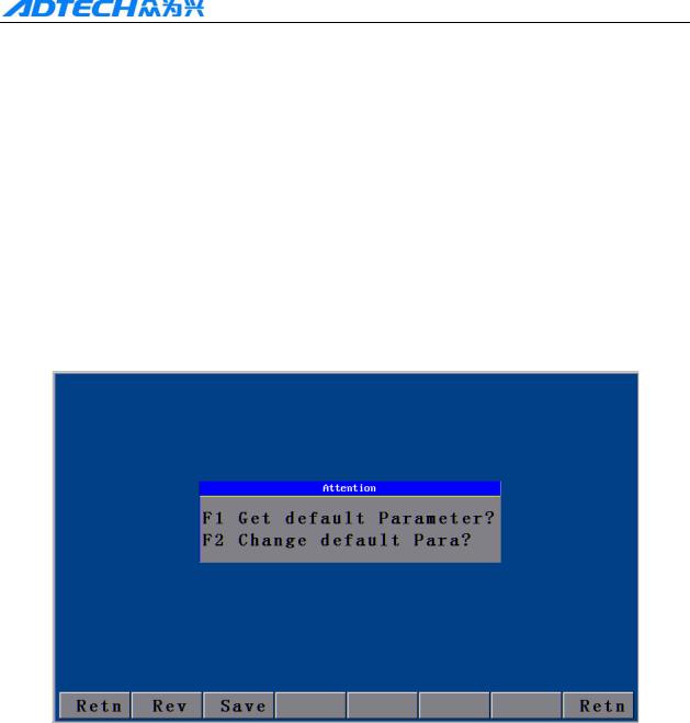
ADT-HC4500 CNC Flame/Plasma Controller
Main menu →Press [F6] to enter the upgrade interface →Press [F6] (Help) to search for the relevant help information.
2. Restore factory default
In case there is a condition of abnormal speed or accuracy due to the improper adjustment of system parameters, you can, in main menu of system, press [F6] (Upgd) →Press [F1] (LEV)→Press [F1] (LEV)→Press [ENTER] to restore the parameters to factory default.
In HC4500, you can also press [F6] (Upgrade) in main menu→ [F3] (Restore) →Press [F1] (Restore)→Press [ENTER] to restore the system configuration files, help files, and figure library files.
Note: If the factory has not saved the factory default, it is not allowed to restore the parameters, and the corresponding dialogue box will be shown.
Picture 2.2 Parameter revert
It can refer to the chape 3 system details operation and specification (6.2) Revert fucntion
3. Figure library
For the convenience of processing and for reducing workload of operators and increasing the usability of system, the system is provided with 33 common figures of processing part and 1 testing figure. In the main menu interface, press [F2] (Grap) to enter the figure library interface as follows, and select the corresponding figure to process.
11
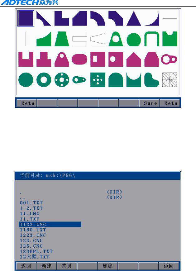
ADT-HC4500 CNC Flame/Plasma Controller
Picture 2.3 Figure library interface
Operation: Press [X+], [X-], [Y+], or [Y-] to move the cursor up, down, left or right. Press [S↑], [S↓] to page up or down, and press [ENTER] to enter the figure.
4. Copying processing files
Insert the USB disk with copied processing files into the USB port of control system. In main menu, press [F3] (Edit) →[F3] (Udsk). If it is connected successfully, the interface will show the file names of files stored in USB disk, as the following picture shows:
Picture 2.4 Copying processing files
At this time, press [Y+] or [Y-] to select the processing files to be copied, and press [F2] (SCpy) or
[ENTER] to copy. After that, a prompt will pop up when you can press any key to return to the main menu
12
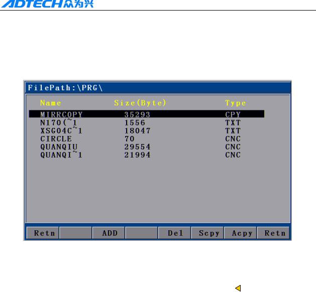
ADT-HC4500 CNC Flame/Plasma Controller
interface.
5. Calling in processing file
In main interface, press [F3] → [F2] to enter the interface for calling in files as follows:
Picture 2.5 File calling interface
After entering the above interface, press [Y+] or [Y-] to select the processing file, and then press [F2] or [ENTER] to confirm and enter the processing code editing interface. You can press  to exit and go back to the main interface, when you can press [F1] to enter the auto interface to carry out the processing with selected files.
6. Adjustment of cutting speed[Adju]
In main interface, you can press [F4] (Para) → [F2] (Speed) to enter speed setting interface.
13
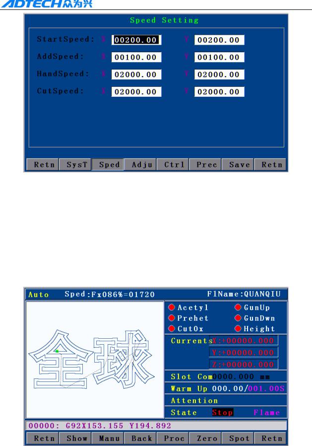
ADT-HC4500 CNC Flame/Plasma Controller
2.6.1 Speed setting interface
First, set the processing speed in the interface as above picture. The speed is the max speed that the actual processing can achieve.
Press [X+], [X-], [Y+], or [Y-] to move the cursor to make the selection, and then press the number key on left of panel to input the value.
After setting the speed, press 
 to return to main menu. Press [F1] again to enter the auto processing interface:
2.6.2 Auto processing interface
14
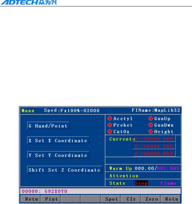
ADT-HC4500 CNC Flame/Plasma Controller
Processing speed is determined by the “CutSpeed” in speed setting interface and the “Speed” rate in auto processing interface.
Actual Processing Speed =CutSpeed × Speed Rate
Note: Speed rate can be adjusted by pressing [F↑] and [F↓] on the panel, or just the [F] key.
7. Adjustment of Manual Speed
In main interface, press [F4] (Para) → [F2] (Speed) to enter the speed setting interface.
See section “HSpeed” for the interface picture. Set the manual speed with the same method as setting cutting speed, and exit to the main interface.
In main interface, press [F1] (Auto) → [F2] (Manual) to enter the manual interface:
2.7 Manual interface Actual Manual Speed = HSpeed × Speed Rate
Note: Speed rate can be adjusted by pressing [F↑] and [F↓] on the panel, or just the [F] key.
8. Control of Turning Quality
During the flame cutting and plasma cutting, there is a process of acceleration and deceleration when turning. Whether the acceleration or the deceleration is properly set or not, it directly influences the cutting quality of the turning. Especially when it is flame cutting, the fast speed of turning may easily cause flameout or halfway cutting; and if the turning speed is too slow, it may easily burn the turning to be
15
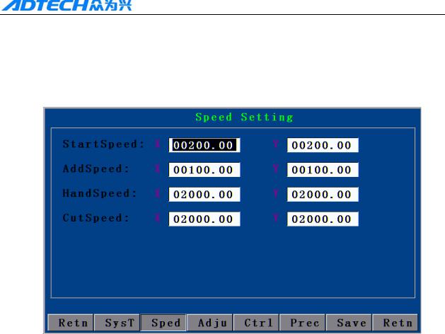
ADT-HC4500 CNC Flame/Plasma Controller
circular arc shape.
The system acceleration and deceleration are set as follows: Press [F4] (Para) in main menu interface, and press [F2] (Speed), then, set the speed in “StrSpeed” and “AddSpeed” (See picture below). Detailed definitions are as follows:
2.8Speed settings
1.[StrSpeed]—Start-up speed: Track-Move, a speed of starting up. For example, if the “StrSpeed” is set to be 300, the system speed is 0.3m at the just beginning. The value of start-up speed is determined by the processing speed. The following list shows the reference value of start-up speed; actual data are subject to the on-scene cutting effect.
|
CutSpeed (mm/minute) |
StrSpeed (mm/minute) |
|
100-200 |
100 |
|
200-500 |
200 |
|
500-700 |
300 |
|
700-800 |
500 |
|
800-1000 |
600 |
|
1000-1300 |
700 |
|
1600-2000 |
1000 |
|
2000-3000 |
1500 |
|
3000-4000 |
2000 |
|
Table 2.8.1 |
|
|
16 |

ADT-HC4500 CNC Flame/Plasma Controller
2.[AddSpeed]— Acceleration: It is an average increment of increasing the processing speed from start-up speed to the highest speed. For example, if the start-up speed is 300, acceleration is 100, and highest speed is 1000, then, the speed is increased to 300, 400, 500…1000 at 100 intervals; if the acceleration is 50, then, the speed is increased by 50 each time.
The acceleration is determined by the Precision (In main menu, press [F4] (Para) → [F5] (Prec).
Precision: refer to the distance the corresponding machine moves when the control system gives an impulse.
The following list shows the reference value of impulse equivalent and the acceleration; the actual data are subject to the on-scene cutting effect.
|
Precision |
Addeleration (mm/minute) |
|
0.001000-0.002000 |
10 |
|
0.002000-0.003000 |
20 |
|
0.003000-0.004000 |
30 |
|
0.004000-0.005000 |
40 |
|
0.005000-0.006000 |
50 |
|
0.006000-0.007000 |
60 |
|
0.007000-0.008000 |
70 |
|
0.008000-0.009000 |
80 |
|
0.009000-0.010000 |
90 |
|
0.010000-0.011000 |
100 |
|
0.011000-0.012000 |
110 |
|
0.012000-0.013000 |
120 |
Table 2.8.2
9. Adjustment of preheating time in flame cutting [Adju]
In main menu, press [F4] (Para) → [F4] (Ctrl) to set the “Preheat Delay” in the second row as the required time.
17
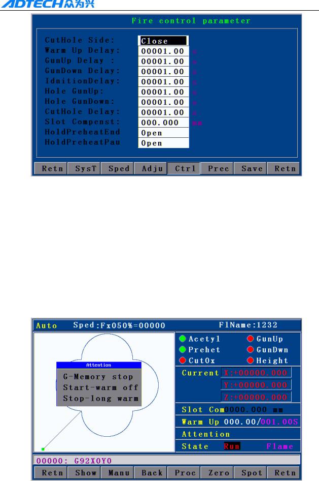
ADT-HC4500 CNC Flame/Plasma Controller
2.9.1 Control interface
In auto cutting interface, it will carry out preheating before perforating. Total preheating time and the current preheating time will be shown on the right bottom of the interface; on the left bottom there will show “Record & GO, Press [G]; Stop, press [START]; Go-on, Press [STOP].” As prompted, if you press [START], the system will stop preheating immediately and go to the next action without saving the preheating time. If you press [STOP], the preheating time will be extended without limit. Press [G] to stop preheating, and the system will save the “Current preheating time” automatically as the “Preheating time” for the future.
In main menu, press [F1] (Auto):
2.9.2 Preheating in auto interface
18

ADT-HC4500 CNC Flame/Plasma Controller
10. Power Failure Treatment
In order to avoid the waste of raw materials caused by the sudden power failure, the system equips with a power-off protection function. If the device is powered off during the processing, the system will automatically save the last processing track as a break point. When the power supply is resumed and you want to resume the coordinate before power-off, you just have to press [F1] (Auto) in main menu → [F6] (Break point) or [F1] (Auto) → [F4] (Break point).
Note: Do not move the cutting nozzle when the power is off, and make sure to set the current coordinate when the power is resumed; otherwise, all the memory coordinate will be wrong.
11. Break point setup
If you exit the automatic processing interface (press [F1] (Auto) to enter) and want to return next time, you need to resume to the current stop coordinate. This can be made by pressing “Pause” during the automatic processing and pressing [F6] (Spot), then, the system will automatically save the current processing point (where the cutting nozzle is located) as a break point. This point is saved forever; no matter it is power off or on. The coordinate will be the saved break point coordinate when you enter the “Auto” interface next time, as long as the current program has not changed.
If you restart the device after the power-off, you just have to press [F6] (Spot ) in the “Auto” interface to restore the break point, and press the [Start] key to resume processing.
12 Change of cutting gun nozzle
If cutting gun nozzle is damaged during the processing, please follow the following steps to change it:
c In main menu, Press [F1] (Auto) → d Press [Stop] key → e Press the corresponding [X+], [X-], [Y+],
and [Y-] keys to move the cutting gun to a proper place for changing the nozzle →f Press [START] → g
select the relevant item in the popped up dialogue box as Picture 2.12 → h Press [ENTER], the coordinate
will be moved to the current break point automatically and proceed the processing of selected item.
19
![]()
ADT-HC4500 CNC Flame/Plasma Controller
2.12 Change of cutting gun nozzle
FBack and Cutting : Go back to the interrupt with no cut then cut continue the program. FBack and Stop : Go back to the interrupt with no cut then stop program..
CBack and Cutting : Go back to the interrupt with cutting then then cut continue program. Process ringht here : cut continue program right here.
13. Displacement perforating
|
A |
B |
|||||
|
B |
||||||
|
Picture 2 |
||||||
|
Picture 1 |
As picture 1, the outer is square steel plate and the inside rectangle is the workpiece to be cut. Assuming that it is to cut the work piece from point A and the steel plate is of thick materials; then, it will cost a lot of time to perforate. However, if it is to cut from the edge of steel plate (point B), the time of preheating perforating may be saved. Detailed operations are as follows:
c In automatic processing → d Press [STOP] → e Press the corresponding X, and Y keys to move the cutting gun to the edge of the steel plate →f Press [Start] again →g Select the relevant item in the popped up dialogue box → h Press [ENTER], the coordinate will be moved to the current break point automatically and
proceed the processing of selected item.
20

ADT-HC4500 CNC Flame/Plasma Controller
14. Movement of work piece
|
Work piece 2 |
|||||||||
|
Work piece 2 |
|||||||||
|
Work piece 1 |
Work piece 1 |
||||||||
|
Picture 1 |
Picture 2 |
To save the steels during the processing, you can move the tracks of work piece to a certain place for processing when cutting some kinds of figures. As shown in above pictures, the out frame is the steel plate, and the inside frame is the figure to be cut. For example, it may waste many materials if you cut the “work piece 2” directly after having cut the “work piece 1”, because they are a certain distance away. Therefore, you can move the track of work piece to a proper place as Picture 2 before cutting, which can save many materials. Detailed operations are as follows:
Press [STOP] key after you have cut the “work piece 1” → Press [X+], [X-], [Y+], and [Y-] to move the cutting gun to the proper position.
15. Line and point selection
This function allows you to select any line of G code of the figure for processing.
In main menu, press [F1] (Auto) → [F4] (Grap) → [F4] (Pro) → [F2] (ChoG) to enter the interface of positioning mode as follows:
21
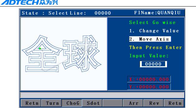
ADT-HC4500 CNC Flame/Plasma Controller
Picture 2.15.1 Positioning mode of line selection
Direct change coordinate: the cutting gun does not move, but the coordinate is changed to the coordinate of this line directly.
Auto move Gun: the cutting gun moves from the current position to the coordinate of selected program line.
You can press [Y+] or [Y-] to change the mode of positioning when selecting line, and press [ENTER] to select the line number (as Picture 2.15.2 shown below).
Input the line number by pressing the number key and then press [ENTER]. In case of doing fine adjustment, you can press [X+] or [X-] to select the next line number.
16. Array
When you need to cut a single figure on big steel plate for several times, you can use the array function to realize the simple array of this repeated figure.
In main menu interface, press [F1] (Auto) → [F4] (Grap) → [F4] (Pro):
22
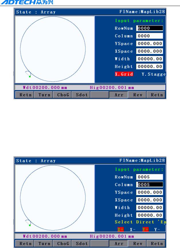
ADT-HC4500 CNC Flame/Plasma Controller
Picture 2.16.1 before arraying (Processing interface)
The acquiescent deviant is the space usage size as aboce picture, which it means the single graph height and width. Suitable adjust the width and height can make the arraying more reasonable.
Press the No. key input the parameter value, press Y+ Y- select item of paramters, input correct parameter, press Confirm enter into the direction seletion of arraying.
In above interface, press [F5] (Arr) to enter the array parameter setting interface.
Picture 2.16.2 Array parameter settings
Press X+ X- Y+ Y- select cursor movement to arraying direction, after selected, press Confirm , finished all of the step of arraying, graph will finished array immideately.
23
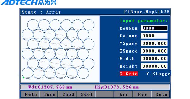
ADT-HC4500 CNC Flame/Plasma Controller
Picture 2.16.3 After array graph
Matters need attention when you operate arraying
1)After the array, it will not save the original process file, like stop coordinate etc.
2)After Array, press Retn enter into dealing interface, It can check if the size suitable the plate or not. Afresh Array press F6 (restore)
17. Mirror
If you need to exchange the start point and the final point of the figure horizontally at 180˚ during the cutting, you can do it by mirror function.
Press [F1] (Auto) → [F4] (Figure) → [F4] (Process) → [F1] (Rotate) → and press [F1] (Y mirror) / [F2] (X mirror) / [F3] (XY mirror). As shown in the following picture:
24
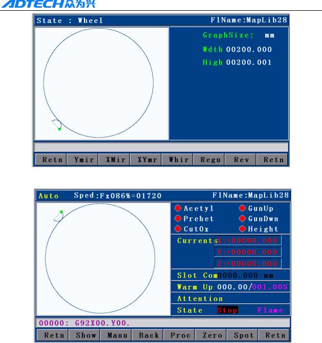
ADT-HC4500 CNC Flame/Plasma Controller
Picture 2.17.1 Before X mirroring
Picture 2.17.2 After X mirroring
18. Rotation
Sometimes, the position and angle of the steel plate are required to meet the XY axis of the cutting machine during the cutting. However, in the actual processing, it is hard to avoid the XY axes on steel plate deviating from the XY axes of cutting machine for an angle.
In virtue of rotation function, it is allowed to achieve the auto calibration of steel plate so that you do not have to move the steel plate or cutting machine. The operations are as: in main menu, press [F1] (Auto) → [F4] (Figure) → [F4] (Process) → [F1] (Rotate) → [F4] (Rotate), and then input the rotation parameter to finish the figure rotation.
25
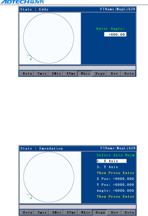
ADT-HC4500 CNC Flame/Plasma Controller
Picture 2.18 Rotation
19. Calibration
If rotation angle is uncertain when calibrating the steel plate, we can get a correct rotation angle by calibration function.
First, a reference axis is required, around which the figure is rotated at a certain angle when calibrating. To select the reference axis, press [F1] (Auto) in main interface → [F4] (Figure) → [F4] (Process) → [F1] (Rotate) → [F5] (Calibrate), and a dialogue box will show up for selecting the reference axis (HC4200 can only take X as the reference axis).
Picture 2.19.1 Selection of calibration reference
Reference axis X: the offset angle of steel plate is the angle formed by X axis of steel plate
26
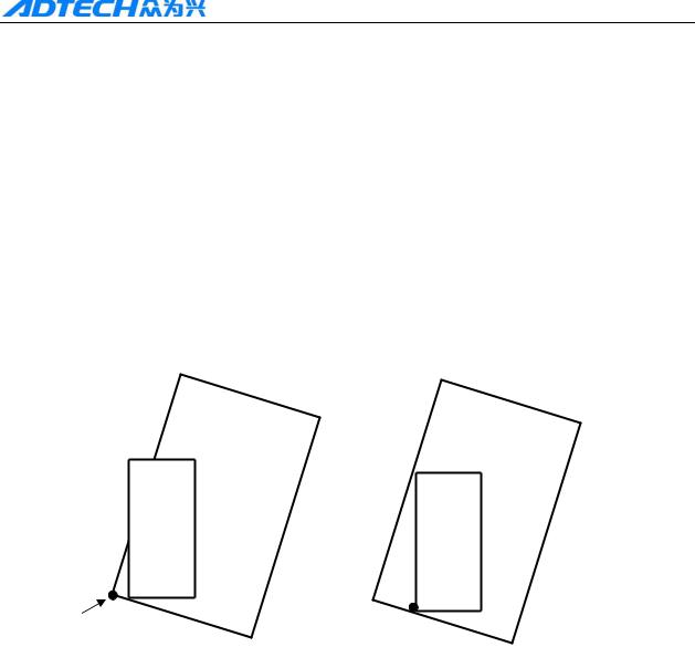
ADT-HC4500 CNC Flame/Plasma Controller
and the X axis of reference coordinate.
Reference axis Y: the offset angle of steel plate is the angle formed by Y axis of steel plate and
the Y axis of reference coordinate.
Press X+ X- Y+ Y- to select the move cutting gun, at the same time, the system will calculate the angel automationly.
The following calibration takes X axis as the reference axis.
The principle of calibration taking X axis as reference axis is as follows:
A
1 In Picture 1, the large frame (Real line) is the steel plate, the small frame (Dashed line) is the figure to be cut, and point A is the start point of the cutting gun. If it is cut according to Picture 1, the figure outside may not be cut; and if it is cut when the start point is moved to the middle of the steel plate as Picture 2, obviously it will waste the steel plate.
2 At this point, without moving the steel plate, you just have to figure out the slope angle of the plate, and incline the figure to be processed at the corresponding angle before cutting effectively.
27
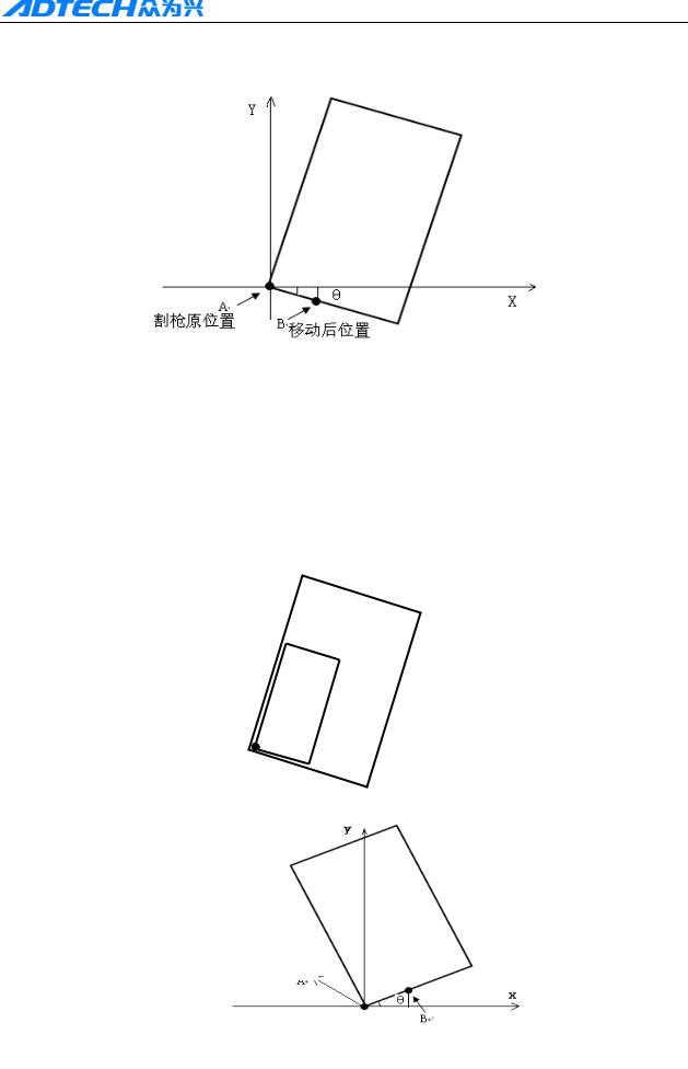
ADT-HC4500 CNC Flame/Plasma Controller
Way of calibrating the steel plate:
|
Original position |
||
|
Position after the move |
||
1 As above picture, point A is the start point of cutting gun. You can figure out the slope angle of the steel plate by moving the cutting gun to any point of its base line. Press [X+] → [Y-], or [Y-]
→ [X+]; then, press [ENTER] to confirm.
2 Then, the figure displayed on the controller will be rotated at a certain degree. The position of figure to be processed and the steel plate is shown as follows:
3 If the steel plate is inclined as follows, then, the calibration method is as below:
Original position
Position after the move
28
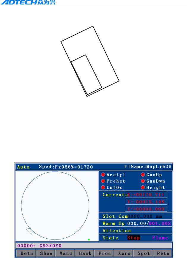
ADT-HC4500 CNC Flame/Plasma Controller
Press [X+] → [Y+], or [Y+] → [X+], then, press [ENTER] to confirm. The position of
figure to be processed and the steel plate is shown as follows:
20 Tool Setting
Main Interface after power on, press F1 Auto— F4 Graph, Enter into Graph track follow
interface, Press key G .
Graph Original start point will turn to position of lower left quarter, Press Key G , The
graph start point will positioned 5 directions like original point, lower left quarter, Lower Right
Corner, top right corner, top left corner.
Picture 2.20 Positioning process Set start to lower right corner
The program will restore automationly when used this fuction.
When you press key of Start for processing, cutting gun will start move from “select start” to program original point, then make the processing
29
![]()
ADT-HC4500 CNC Flame/Plasma Controller
Chapter III Operations and Details
1. Auto
In main interface, press [F1] (Auto) to enter the auto processing interface as follows:
Picture 3.1 Flame mode
Picture 3.1 Plasma mode
30

ADT-HC4500 CNC Flame/Plasma Controller
Picture 3.1 Flame mode interface details:
1)Speed in %: can be adjusted by pressing [F↑] and [F↓]
2)Current moving speed
3)Name of processing file
4)Status of all electrovalves
5)Current The real-time coordinate value of X ,Y,Z
6)Current Gun gas of cutting diameter conpensation
7)Preheating time of preheat oxygen when perforating in flame cutting
Current working status of the system
9)Cutting machine model remind
10)System cuttent working status remind
11)System current remind of function mode status
12)Track display of current process graph
For plasma and flame mode interface, the difference is that the plasma mode does not have
preheating time and some electrovalves are different.
1.1 Details of program running
In interface as shown in Picture 3.1 and 3.1 , you can press [Start] to run the current program. Once you have pressed the [Start] key, in any cutting mode, the cutting gun will start perforating on steel plate (M07 is default as perforating instruction), and then cutting. After the cutting, close the cutting oxygen. For M07 instruction, see section 4 of Chapter IV in this user manual.
If pause key is pressed during the cutting, the interface will be shown as Picture 3.1.1 and [F2] is changed from [Manual] to [Forward]. If you press [F2] [Forward], the machine will travel forward along the track, and when you press [ ] or [ ], [Forward] will be changed to [Manual], and the interface operations are of the same.
31

ADT-HC4500 CNC Flame/Plasma Controller
Picture 3.1.1 Pause in auto mode
Processing in pause (displacement perforating and gun changing)
Picture 3.1.1.2 Pause processing
During the cutting, if [Pause] is pressed, according to whether the cutting gun has been moved manually, there are the following treatments:
1)If there is no manual movement after the pause, the controller will start perforating once you press the [Start] button, and then proceed running the program.
2)After the pause, if the cutting gun is moved deviating from the running track of processing file, when you press the [Start] button, the interface as Picture above will show up.
[1]. the controller travels back to where the processing program pauses, enables the cutting
32

ADT-HC4500 CNC Flame/Plasma Controller
cycle, and then runs the processing program.
[2].the controller travels back to where the processing program pauses, and then stops.
[3].the controller enables the cutting at current position, and then returns to where the processing program pauses and runs the processing program. The three options can be selected by pressing [Y+] or [Y-] to move “←” up and down. After that, press [ENTER] to run the relevant function.
[4].Proceed running the program code at offset position, and does not return to where the track is located when paused.
Press [ESC] to cancel, and wait at the current position for the users to decide whether to continue processing.
3) Perforating instruction will be performed automatically according to the program status. You can press pause to stop the M07 instruction.
1.2 Details of submenu in auto interface
1.2.1 Travel
(Auto)→ [F1] (Travel): the system only runs X, and Y tracks, and the switches of preheating oxygen, acetylene, cutting oxygen, arcing, and cornering are not opened. It is for calculating whether the track and the size of running steel plate are correct.
(Auto) → Y , testing plate function. System will run automation an idling process picture of min rectangle figure
Travel and TEST speed is the maximum manual speed, and is not controlled by the speed percentage.
1.2.2 Manual
In main menu → [F1] (Auto) → [F2] (Manual) to enter the manual interface:
33

ADT-HC4500 CNC Flame/Plasma Controller
Picture 3.1.2.2 Manual interface in flame mode
Picture 3.1.2.2 Manual interface in plasma mode
1.2.2.1 Inching
In manual interface as Picture 3.1.2.2, press [F1] (Point), and the above interface will show up when the “Inching” is highlighted, with an input prompt “Input L value” at the bottom of the screen. Press the number keys to input the length of inching, unit in mm. Then, you can press [X+], [X-], [Y+] or [Y-] to allow the motor to run the input length relatively for each time. It’s the same for the plasma function (Picture is omitted)
34
Портальный станок термической резки металла ЭП
- Описание
- Характеристики
- Видео
Особенности оборудования:
- Резка газом/плазмой, быстрое переключение.
- Контроллер высоты дуги плазмы по напряжению (THC)
- Программная коррекция толщины реза
- Программная коррекция укладки листа
- Восстановление по сбою электропитания.
- Гарантия 1 год. Гарантийная и тех. поддержка в России.
- Встроенная библиотека типовых деталей
- Контроллер на русском языке
- ПО для подготовки управляющих файлов на русском языке
- Инструкции на русском языке
| Характеристики |
Портальный станок термической резки металла ЭП |
|
Электропитание |
AC 220V±10%/50/60Hz |
|
Режимы резки металла |
Пропан + O2/Ацетилен + O2/Плазма |
|
Межосевое расстояние по направляющим(mm) |
2500 |
|
Длина направляющих(mm) |
5000 |
|
Размер рабочей зоны(mm) |
2000 × 4000, 2000 × 6000, 2000 × 8000 |
|
Пределы регулировки высоты горелок(mm) |
≤100 |
|
Толщина реза(mm) O2+Пропан Плазма |
5-150 мм определяется используемым источником плазмы |
|
Скорость холостого хода(mm/min) |
0-6000 |
|
Максимальная скорость реза(mm/min) |
0-6000 |
|
Приводы |
Ось X, ось Y, ось Z автоматическая регулировка высоты |
|
Система ЧПУ |
ADTECH HC-4500 (русифицировано) |
|
Программное обеспечение в комплекте поставки |
StankCAM 2.0 (русифицировано) |
Оставить отзыв
Вы недавно смотрели

Наши постоянные клиенты
Каталог
Услуги
Контакты
Specifications:
|
Accompanying Data:
Adtech ADT-HC4500 Welding System PDF Operation & User’s Manual (Updated: Sunday 9th of April 2023 12:50:20 AM)
Rating: 4.3 (rated by 97 users)
Compatible devices: TRI STAR MIG 1636/M, AC2-CW5170S, GA-16C, DIGITECH 400 PULSED, PLANON, MONOMAG 180, MA-400, AUTOMIG190.
Recommended Documentation:
Adtech ADT-HC4500: Text of Operation & User’s Manual
(Ocr-Read Version Summary of Contents, UPD: 09 April 2023)
-
127, ADT-HC4500 Flame/Plasma Cutting Machine CNC System — 126 — Appendix 2: Example of Editing Processing Graphics In the main interface, press [F3] to enter the edit interface, and then press [F1] to create a new processing file, enter the file name, press [OK] to enter file edit inter…
-
20, ADT-HC4500 Flame/Plasma Cutting Machine CNC System — 19 — Return 2.9.1 Control Interface While cutting in Auto interface, the system performs preheating before perforation. At this moment, the lower right of the interface shows the total preheating time and preheated time.…
-
78, ADT-HC4500 Flame/Plasma Cutting Machine CNC System — 77 — Select the output port to set Ignition control: Default Preheating oxygen control: Default �…
-
113, ADT-HC4500 Flame/Plasma Cutting Machine CNC System — 112 — 17 OUT11 Flame cutting preheating oxygen valve control, M24 (ON), M25 (OFF) 18 OUT12 Reserved preheating oxygen control, M26 (ON), M27 (OFF) 19 OUT13 Reserved cutting oxygen/start arc control, M32 (ON), M33 (OFF) 20…
-
72, ADT-HC4500 Flame/Plasma Cutting Machine CNC System — 71 — Plasma Control Parameter Interface Start arc delay Torch up delay Torch down delay Preheating delay �…
-
67, ADT-HC4500 Flame/Plasma Cutting Machine CNC System — 66 — Flame Step Height Adjustment Setting Z Allow Z axis height adjustment: Off Z Z axis pulse equivalent Z Z axis start speed Z �…
-
103, ADT-HC4500 Flame/Plasma Cutting Machine CNC System — 102 — 2. Start arc M12 3. Wait for arc voltage test signal (IN0) When arc starts, the height adjuster initializes the positioning automatically (height adjuster with initial positioning, which is disa…
-
53, ADT-HC4500 Flame/Plasma Cutting Machine CNC System — 52 — 3.1 Submenu description 3.1.1 New Input method: digital 123 Please type the file name: Return / Save / Return Fig. 3.1.1 New File Interface In Fig. 3.1 edit inter…
-
4, ADT-HC4500 Flame/Plasma Cutting Machine CNC System — 3 — Precautions Transportation and storage H The packaging boxes shouldn’t be stacked more than six layers H Do not climb onto, stand on or put heavy objects on the packaging box H Do not drag or convey the prod…
-
131, ADT-HC4500 Flame/Plasma Cutting Machine CNC System — 130 — 5. Four graphics Relative coordinate programming 0000: G92X0Y0 0001: G21 0002: G22 L1 0003: G41 0004: M07 0005: G0 X50 0006: G1 Y200 0007: X200 0008: Y-200 0009: X-200 0010: M08 001…
-
122, ADT-HC4500 Flame/Plasma Cutting Machine CNC System — 121 — Fig. 5.5.4 Note: Do not reel PE end i.e. earth wire into the magnetic ring. 3) A magnetic ring should be added to the end of X, Y axis signal output wire, as shown below:
… -
133, ADT-HC4500 Flame/Plasma Cutting Machine CNC System — 132 — Appendix 3: G Instruction Fact Sheet S/N Instruction name Description 1 G00 Quick positioning (run idle) 2 G01 Linear processing 3 G02 Clockwise circle processing 4 G03 Counterclockwise circle pr…
-
14, ADT-HC4500 Flame/Plasma Cutting Machine CNC System — 13 — Return / Import / Delete / Copy / Copy all / Return Fig. 2.5 File Importing Interface In above interface, press [Y+][Y-] to select a processing file and then press [F2] or…
-
104, ADT-HC4500 Flame/Plasma Cutting Machine CNC System — 103 — M74 Fixed preheating cycle (controlled by time in “Control” interface) M80 General switch; all outputs will be turned off after performing M80
…
Adtech ADT-HC4500: Recommended Instructions
5JE, GF3 DVII, R500-S5003, 13AAB11CH712, R8C/27


-
Valid from serial no. 2170700 159 017 0219CaddyTig HFBruksanvisningBrugsanvisningBruksanvisningKäyttöohjeetInstruction manualBetriebsanweisungManuel d’instructionsGebruiksaanwijzingInstrucciones de usoIstruzioni per l’usoManual de instruçõesÏäçãßåò ÷ñÞóåùòInstrukcja obs³ugi …
CaddyTig HF 11
-
225 AC, 225/150 AC/DC, And 300/200 AC/DCOM-316 087 083U2014−02Visit our website atwww.MillerWelds.comFile: Stick(SMAW)ProcessesStick (SMAW) WeldingDescriptionArc Welding Power Source225 AC Models:225/150 AC/DC Models:300/200 AC/DC Models:Thunderbolt XLR …
Thunderbolt XL 40
-
• Sales and Service through Subsidiaries and Distributors Worldwide •Cleveland, Ohio 44117-1199 U.S.A. TEL: 216.481.8100 FAX: 216.486.1751 WEB SITE: www.lincolnelectric.com• World’s Leader in Welding and Cutting Products •TANDEM MIG 800 AMPERAGE WELDING TORCHOPERATOR’S MANUALIM865February, 2005Safety Depends on YouLincoln arc welding and cuttingequipment is designed a …
TANDEM MIG S22693-121 25
-
Warranty ……………………………………………………………………………………… 2 Identification of the machine ……………………………………………………………. 2 Product specifications ……………………………………………………………………… 2 Dimensions and weight ……………………………… …
Powerduction 160L 11
-
Operating instructions EN Welding machine Taurus 351 Basic FKG Taurus 401 Basic FKG Taurus 351 Basic FKW Taurus 401 Basic FKW Taurus 501 Basic FKW 099-005425-EW501 14.07.2016 Register nowand benefit!Jetzt Registrierenund Profitieren!www.ewm-group.com*For details visitwww.ewm-group.com* …
Taurus 351 Basic FKG 74
-
5013777QUICKGUIDE ZETA 60 I 100DK10A 30A 45A 60A0 5 10 15 200,91,01,11,210A 30A 45A 60A 75A 85A 100A0 5 10 15 20 25 30 350,91,01,11,21,41,51,6Forventet kvalitetssnitDelesnit med nedsat kvalitetZeta 60Zeta 100Tabellen er retningsgivende for valg af dysestr./A sammenholdt medmaksimal godstykkelse ved skæring i sort stål. Ved skæring i andre materialerreduceres den opnåelige sk …
ZETA 60 18
-
…It’s guaranteedto save yourcustomersmoney!This little box could make you very popular…The Beckett HeatManagerTMis apatented,microprocessor controlthat automatically adjusts the burnerrun pattern to match the system’s heatload, substantially improving efficiency.For use on new or existing boilers*, HeatManagerworks with the existing boiler control to deli …
Heat Manager 61572 04 1
-
————-DE Originalbetriebsanleitung————-EN Translation of the original instructions————-FR Traduction du mode d’emploi d’origine————-IT Traduzione del Manuale d’Uso originale————-NL Vertaling van de originele gebruiksaanwijzing————-CZ Překlad originálního návodu k provozu————-SK Prekl …
GIS 121 63
Additional Information:
Operating Impressions, Questions and Answers:
#1
![]()
OFFLINE
008shadow
- Пол:Мужчина
- Из:Almaty
Отправлено 15 Август 2014 — 14:34
Ищу мануал на него и программу. Готовые файлы принимает с расширением *.cnc. Меню все на китайском, на плазморезах похожее управление, но так как там меняется язык здесь не какнает.
Одновременно обрабатывает 2 болясины. Подсобите кто чем.


-
0
- Наверх
#2
![]()
Aleksandr3
- Пол:Мужчина
- Город:Краснодар
- Интересы:Электроника. станки с ЧПУ,музыка.
- Из:Краснодар
Отправлено 15 Август 2014 — 15:11
Единственное, что вот так, с ходу, в голову пришло. Попробуй от Фанука , может, подойдёт. А так, если серьёзнее, надо будет посмотреть. Если что найду — скину на форум.
-
0
- Наверх
#3
![]()
008shadow
- Пол:Мужчина
- Из:Almaty
Отправлено 15 Август 2014 — 15:55
Спасибо. Немного потыкал кнопки- смог запустить файл, который был в памяти. Но без его проги однако не попрет
-
0
- Наверх
#4
![]()
Vadosi4
- Пол:Мужчина
- Город:Москва
- Из:Москва
Отправлено 15 Август 2014 — 17:51
У меня мануал Adtech на английском на 30%-40% не соответствовал действительности. Проверенно было на 2-х стойках.
Может вам повезет — ADT-HC4500.
-
0
- Наверх
#5
![]()
008shadow
- Пол:Мужчина
- Из:Almaty
Отправлено 17 Август 2014 — 11:41
У меня мануал Adtech на английском на 30%-40% не соответствовал действительности. Проверенно было на 2-х стойках.
Может вам повезет — ADT-HC4500.
Такой есть в наличии и однако не со всем то. Благодарю за отклик
-
0
- Наверх
#6
![]()
courage
- Пол:Мужчина
- Город:Новосибирск, Россия
- Из:Новосибирск
Отправлено 23 Октябрь 2014 — 20:18
Вообще мой совет поменять систему управления. Пробовали с этими контроллерами работать на разных станках и на качельных для радиусных фасадов, и на обычных фрезерах. Мануалы не соответствуют действительности, обо всё приходится догадываться и действовать методом тыка.
Разводка электрическая не совсем адекватная. Техподдержки нифига не отвечает и я думаю ответит только если звонить им из китая и ругаться китайским матом.
В итоге поменяли все контроллеры на Ncstudio, выбросили Adtech в металлолом.
-
0
Опыт прямопропорционален количеству испорченного оборудования.
Сертифицированный инженер по обслуживанию источников механизированной резки и система автоматизации Hypertherm.
Представитель и инженер сервисной и техподдержки компании Weihong (Ncstudio, NK105, NK260, NK300) на территории России.
- Наверх
Оригинальная HC4500 3 оси плазменной резки с ЧПУ Пламя машина для контроллер
Лучшее качество HC4500 3 оси CNC плазменная машина для резки пламени контроллер
Характеристики HC4500:
Подгонянное программное обеспечение: сильный> он может применяться для плазменной, пробивной и гравировальной функции
В пределах одной машины, простая лазерная резка и т. Д.
USB, RS232 серийный Коммуникационный контроль, непосредственно считывает файл купить U диск
Функция восстановления точки разрыва
Задержка, подогрев, перфорация, изменение сопла, движущихся частей, движущихся частей и т. Д. Контроль процесса;
Функция графической работы, поддерживающая вращение, коррекцию и
Функция зеркального изображения и т. Д.;
Графическая Библиотека: 63 графа, которые могут отрезать отверстие или нарезать по своему выбору;
Плазма/пламя контроллер может контролировать 3 шаг/Серводвигатель в то же время, который принимает
Сомневающаяся ось в одно время или разработка 3 оси в соответствии с запросами клиентов;
Большой файл процесса хранения: 256 м, требует сложного/большого запуска программы
И обработка всех фотоэлектрических изоляции управления, супер большой анти-интерфейс
Возможность; Поддержка многоязычного дисплея;
7-дюймовый реальный цвет дисплея экран, дружелюбны и легко операционный интерфейс,
Технология многозадачного управления в реальном времени и технология интерполяции оборудования
Высокоскоростной микропроцессор ARM9 и супер большой программируемый FPGA. Он принимает ARM9
Процессор, супер большой.
Цифровой вход:
Канал: 32, все Фотоэлектрические изоляции
Входное напряжение: 12-24 В постоянного тока
Высокий уровень> 4,5 V
Низкий уровень <1,0 V
Напряжение изоляции: 2500 В постоянного тока
Подсчет входного сигнала:
Канал: шпиндель ABZphase кодирования ввода, все Фотоэлектрические изоляции
Максимальная частота подсчета: 2 МГц
Входное напряжение: 5-24 В постоянного тока
Высокий уровень> 4,5 V
Низкий уровень <1,0 V
Напряжение изоляции: 2500 В постоянного тока
Импульсный выход:
Канал: 3 оси импульса, 3 оси направления, все фотогальванические изоляции
Максимальная частота импульса: 2 МГц
Тип выхода: 5 В дифференциальный выход
Выходной режим: пульс + направление или Пульс + пульс
Цифровой выход:
Выходной канал: 16, все Фотоэлектрические изоляции
Тип выхода: NPN open-collectorout поставить 12-24 В постоянного тока, максимальный ток 100 мА.
RS-232 скорость передачи данных (bps):
1200,2400,4800,9600,19200,38400,57600,115200


Доставка
Он будет отправлен в течение 1-3 дней после четкой оплаты и занимает 4-7 дней для доставки в вашу мастерскую.DHL,UPS.Fedex, TNT и EMS и т. Д. Курьер и Почта Китая, HK Post avalible.
Напоминание о кэшбэке: Что бы получить кешбек при покупке этого или другого товара на Aliexpress. Перейдите по ссылке ниже, затем на открывшейся странице авторизуйтесь/зарегистрируйетсь, далее появиться подробная инструкция как получать кэшбэк при покупках на Алиэкспресс.
Кэшбэк в интернет магазинах
Отзывы покупателей
*о других товарах
Отзывы
Здесь вы можете оставить свой отзыв о данном товаре.
![]()
ADT-HC4500
CNC Flame/Plasma Controller
User Manual
ADTECH (SHENZHEN) CNC TECHNOLOGY CO., LTD
5th Floor, 27-29th Building, Tianxia IC Industrial Park, Yiyuan road, Nanshan District, Shenzhen Post code: 518052 Tel: 0755-26099116 Fax: 0755-26722718
E-mail: sales02@machine-controller.com http://www.machine-controller.com
ADT-HC4500 CNC Flame/Plasma Controller
Copyright
All property rights of this user manual are reserved by Adtech (Shenzhen) CNC Technology Co., Ltd (ADTECH for short). No institution or person is allowed to counterfeit, copy, transcribe or translate this user manual without permission of ADTECH. This user manual does not include warranty, standpoint expression, or other hints in any form. ADTECH does not bear any responsibility for any data outflow, benefit loss or business termination due to the product info contained or mentioned by this user manual. All products and data mentioned are for reference only. Contents are subject to change without prior notice.
All Rights Reserved
ADTECH (SHENZHEN) CNC TECHNOLOGY CO., LTD
1
ADT-HC4500 CNC Flame/Plasma Controller
Upgrade Information
|
Item No. |
Version No. |
Revision Date |
Remark |
|
HC4500 |
0.1.4 |
2011/02/24 |
Edition 4 |
|
(General) |
|||
Note: Meanings of the three numbers in version number are as follows:
|
0 |
1 |
4 |
||||||
|
Library main version No. |
Library secondary version No. |
Reserved |
Remark:
1.This user manual is strictly emended and checked by ADTECH (SHENZHEN) CNC TECHNOLOGY CO., LTD, however, it is not guaranteed that the user manual has no any mistake or error.
2.ADTECH (SHENZHEN) CNC TECHNOLOGY CO., LTD commits itself to improving the product functions and the service quality consistently. Therefore, the company reserves the right of changing any products as described, any software program, and the content of the user manual, without prior notice.
2
ADT-HC4500 CNC Flame/Plasma Controller
Safety Notice
Read this safety notice before operating.
I. Notice
1 Notice on safety:
Original copy of safety notice should be dispensed to every operator.
Do not open the controller cover without permission; otherwise, it would be out of the range of guarantee.
Cut off the power supply in case the machine is not used for a long time.
Pay attention not to drop any dust or iron powder into the controller.
Do not pour any liquid into the controller.
Handle with care, and do not cause any damage.
Abide by the accident prevention provision and regulations.
Abide by the accident prevention provision and regulations on Oxygen cutting.
Wear the mask when performing the plasma arc cutting, for the plasma arc will generate UV-b radiation.
2 Notice on correct application:
Our control system is capable of anti-interfering, but it is still required that your plasma power supply have shielding function and the plasma controller have good grounding. Otherwise, it will bring serious result.
Please set all parameters of the controller strictly according to the user manual; otherwise, it may lead to failure of control system or even cause serious consequences.
The controller uses the 24V DC power supply. To avoid short circuit, please pay attention to the voltage, negative or positive electrode of power supply when installing.
Do not insert or pull out any output plug of controller while the power supply is connected; otherwise, it will damage the inside of controller.
If the output relay is non-solid-state relay, a freewheeling diode should be connected in parallel on relay coil. Check the applied power supply to see whether it is up to requirements, avoid burning out the controller.
Controller lifetime has a great relationship with ambient temperature. Install a cooling fan if the temperature in processing area is too high. The allowable ambient temperature of the controller is between 0°C and 60°C.
Do some protection measures if the machine is used in high temperature, damp, or dusty environment, or environment with corrosive gas.
In place with strong vibration, add a rubber anti-vibration pad to weaken the vibration.
3
ADT-HC4500 CNC Flame/Plasma Controller
II. Statement:
We offer one year factory warranty or lifetime maintenance for any malfunction arising under the normal use. In case of man-made damage or if the warranty expired, ADTECH will charge a certain cost price of parts. However, the warranty is not applied to the following conditions:
The label of serial number is torn down.
Any damage caused by personal factors
Any damage caused by natural disasters
Disassembly, modification, or repair without permission
III. Maintenance
1.Notice for maintenance and inspection:
Cut off the power supply of major loop before maintaining or repairing the controller.
To prevent the accident, the operator should confirm the power supply is cut off.
2.Inspection item and period:
Under the general operating conditions (Daily average 30°C, load rate 80%, operating ratio 12 hours per day), carry out the following items to do the route and periodical inspections.
|
● Check whether the ambient temperature, dust and foreign |
|||
|
Route inspection |
Daily |
matters exceed the criteria |
|
|
● Check whether there is abnormal vibration or sound |
|||
|
Periodical inspection |
Half year |
● |
Check whether the firm parts are loosened |
|
● |
Check whether the terminal board is damaged |
||
4
ADT-HC4500 CNC Flame/Plasma Controller
|
Content |
|||
|
Upgrade Information ……………………………………………………………………………………………….. |
2 |
||
|
Safety Notice …………………………………………………………………………………………………………… |
3 |
||
|
Chapter I. Introduction ……………………………………………………………………………………………. |
8 |
||
|
1. |
Function introduction ……………………………………………………………………………………………………………….. |
8 |
|
|
2. |
Features ………………………………………………………………………………………………………………………………….. |
8 |
|
|
3. Application environment …………………………………………………………………………………………………………… |
9 |
||
|
Chapter II Quick Start……………………………………………………………………………………………. |
10 |
||
|
1. |
Help information ……………………………………………………………………………………………………………………. |
10 |
|
|
2. |
Restore factory default ……………………………………………………………………………………………………………. |
11 |
|
|
3. |
Figure library…………………………………………………………………………………………………………………………. |
11 |
|
|
4. |
Copying processing files …………………………………………………………………………………………………………. |
12 |
|
|
5. |
Calling in processing file…………………………………………………………………………………………………………. |
13 |
|
|
6. |
Adjustment of cutting speed[Adju] …………………………………………………………………………………………… |
13 |
|
|
7. |
Adjustment of Manual Speed…………………………………………………………………………………………………… |
15 |
|
|
8. |
Control of Turning Quality………………………………………………………………………………………………………. |
15 |
|
|
9. Adjustment of preheating time in flame cutting [Adju] ……………………………………………………………….. |
17 |
||
|
10. Power Failure Treatment ……………………………………………………………………………………………………….. |
19 |
||
|
11. Break point setup………………………………………………………………………………………………………………….. |
19 |
||
|
12 Change of cutting gun nozzle……………………………………………………………………………………………….. |
19 |
||
|
13. Displacement perforating ………………………………………………………………………………………………………. |
20 |
||
|
14. Movement of work piece……………………………………………………………………………………………………….. |
21 |
||
|
15. Line and point selection ………………………………………………………………………………………………………… |
21 |
||
|
16. Array………………………………………………………………………………………………………. |
|||
|
17. Mirror …………………………………………………………………………………………………………………………………. |
24 |
||
|
18. Rotation ………………………………………………………………………………………………………………………………. |
25 |
||
|
19. Calibration…………………………………………………………………………………………………………………………… |
26 |
||
|
20 Tool Setting ……………………………………………………………………………………………………………………….. |
29 |
||
|
Chapter III Operations and Details…………………………………………………………………………. |
30 |
||
|
1. Auto……………………………………………………………………………………………………………………………………… |
30 |
||
|
1.1 |
Details of program running …………………………………………………………………………………………….. |
31 |
|
|
1.2 |
Details of submenu in auto interface ………………………………………………………………………………… |
33 |
|
|
1.3 |
Basic operations ……………………………………………………………………………………………………………. |
40 |
|
|
2. |
Figure library…………………………………………………………………………………………………………………………. |
41 |
|
|
2.1 |
Operations ……………………………………………………………………………………………………………………. |
41 |
|
|
2.2 |
Hole-cutting and slicing …………………………………………………………………….. |
||
|
2.3 |
Edge-sharing cut……………………………………………………………………………….. |
||
|
3. |
Edition ………………………………………………………………………………………………………………………………….. |
42 |
|
|
3.1 |
Explanation of sub-menu………………………………………………………………………………………………… |
43 |
|
|
3.2 |
Editing processing file……………………………………………………………………………………………………. |
50 |
|
|
3.3 |
Basic operations ……………………………………………………………………………………………………………. |
53 |
|
|
4. |
Parameter………………………………………………………………………………………………………………………………. |
54 |
|
|
4.1 |
System …………………………………………………………………………………………………………………………. |
54 |
|
|
4.2 |
Speed …………………………………………………………………………………………………………………………… |
56 |
|
|
5 |
|
ADT-HC4500 CNC Flame/Plasma Controller |
||
|
4.3 Adjustment (Adju)…………………………………………………………………………………………………………. |
58 |
|
|
4.4 |
Control (Ctrl)………………………………………………………………………………………………………………… |
58 |
|
4.5 Accuracy (Prec) …………………………………………………………………………………………………………….. |
60 |
|
|
4.6 |
Save …………………………………………………………………………………………………………………………….. |
62 |
|
5. Diagnosis (Diag) ……………………………………………………………………………………………………………………. |
62 |
|
|
5.1 |
Sub-menu …………………………………………………………………………………………………………………….. |
62 |
|
6. Upgrade (Upgd)……………………………………………………………………………………………………………………… |
65 |
|
|
6.1 |
Description of sub-menu ………………………………………………………………………………………………… |
65 |
|
6.2 |
Restoration (Rev) ………………………………………………………………………………………………………….. |
66 |
|
6.3 |
Upgraded by USB disk (Udsk)………………………………………………………………………………………… |
69 |
|
6.4 |
Backup/Restoration of HC6500 system files…………………………………………. |
|
|
6.5 |
Upgrade via PC ………………………………………………………………………………… |
|
|
6.6 |
Recording program………………………………………………………………………………………………………… |
73 |
|
6.7 |
Upgrade in BIOS interface via PC …………………………………………………………………………………… |
74 |
|
7. |
Help system…………………………………………………………………………………………………………………………… |
76 |
|
|
8. |
Multi-language operations……………………………………………………………………………………………………….. |
77 |
|
|
Chapter IV Instruction System ……………………………………………………………………………….. |
79 |
||
|
1. |
Explanation of programming symbol …………………………………………………………………………………….. |
79 |
|
|
2. |
Coordinate explanation …………………………………………………………………………………………………………. |
79 |
|
|
2.1 |
Relative coordinate………………………………………………………………………………………………………… |
79 |
|
|
2.2 |
Absolute coordinate……………………………………………………………………………………………………….. |
80 |
|
|
3. |
G instruction………………………………………………………………………………………………………………………….. |
80 |
|
|
3.1. G92 reference point setup………………………………………………………………………………………………. |
80 |
||
|
3.2. G21/G20 Metric /Imperial setting …………………………………………………………………………………… |
80 |
||
|
3.3. G00 idle motion……………………………………………………………………………………………………………. |
81 |
||
|
3.4. G01 linear cutting…………………………………………………………………………………………………………. |
81 |
||
|
3.5. G02/G03 circular arc cutting………………………………………………………………………………………….. |
81 |
||
|
3.6. G04 Pause/Delay instruction ………………………………………………………………………………………….. |
82 |
||
|
3.7. G26, G27, G28 Back to reference point …………………………………………………………………………… |
82 |
||
|
3.8. G22/G80 cycle processing……………………………………………………………………………………………… |
82 |
||
|
3.9. G81 workpiece counting ……………………………………………………………………………………………….. |
83 |
||
|
3.10. G91/G90 relative/absolute coordinate programming ……………………………………………………….. |
83 |
||
|
3.11. G41/G42/G40 …………………………………………………………………………………………………………….. |
83 |
||
|
4. |
Common M instructions………………………………………………………………………………………………………….. |
84 |
|
|
Chapter V Hardware ……………………………………………………………………………………………… |
86 |
||
|
1. |
Overall dimension ………………………………………………………………………………………………………………….. |
86 |
|
|
2. |
System input/output interface…………………………………………………………………………………………………… |
87 |
|
|
2.1 |
Back cover……………………………………………………………………………………………………………………. |
87 |
|
|
2.2 |
Specifications ……………………………………………………………………………………………………………….. |
87 |
|
|
2.3 |
Electrical connection ……………………………………………………………………………………………………… |
88 |
|
|
3. |
Connection mode of motor………………………………………………………………………………………………………. |
96 |
|
|
3.1 |
Connection of Differential Driver ……………………………………………………………………………………. |
96 |
|
|
3.2 |
Connection of common-anode driver……………………………………………………………………………… |
100 |
|
|
3.3 |
Connection of Panasonic servo motor …………………………………………………………………………. |
101 |
|
|
4. |
Key Points for Installation & Test …………………………………………………………………………………………… |
101 |
|
|
4.1 |
NCS’s Requirement on Impulse Equivalent Value……………………………………………………………. |
101 |
|
|
6 |
|
ADT-HC4500 CNC Flame/Plasma Controller |
||
|
4.2 Current adjustment of driver …………………………………………………………………………………………. |
102 |
|
|
4.3 Test method of impulse equivalent…………………………………………………………………………………. |
102 |
|
|
4.4 Anti-interference measures……………………………………………………………………………………………. |
102 |
|
|
Chapter VI Troubleshooting………………………………………………………………………………….. |
104 |
|
|
1. |
Why the U-disk cannot be read? …………………………………………………………………………………………….. |
104 |
|
2. |
Why there is an error in the cutting? ……………………………………………………………………………………….. |
104 |
|
3. |
Why the cutting quality of the turning is poor?…………………………………………………………………………. |
104 |
|
4. |
Why the cutting square is changed to rectangle? ………………………………………………………………………. |
104 |
|
5. |
Why the cutting circle is changed to ellipse? ……………………………………………………………………………. |
104 |
|
6. |
Why there is wave shake in the opposite angles when cutting the circle? …………………………………….. |
104 |
|
7. |
Why the motor does not work or is similar to death when it is in “Auto” state? ……………………………. |
104 |
|
8. |
Why the motor does not work or is similar to death when it is in “Manual” state? ………………………… |
105 |
|
9. |
The processing code has the “Return” instructions. However, why the device does not return to the |
|
|
home position after having finished the track?……………………………………………………………………………… |
105 |
|
|
10. Why the right angle of the cutting square is not vertical? …………………………………………………………. |
105 |
|
|
11. Why the anti-interference performance of plasma is poor?……………………………………………………….. |
105 |
|
|
12. Why, one of the solenoid valves cannot work? ……………………………………………………………………….. |
105 |
|
|
Annex II Illustration of edition and processing………………………………………………………. |
107 |
|
|
1. |
Standard circle……………………………………………………………………………………………………………………… |
108 |
|
2. |
Square…………………………………………………………………………………………………………………………………. |
109 |
|
3. |
Triangle ……………………………………………………………………………………………………………………………… |
110 |
|
4. |
Quincunx ……………………………………………………………………………………………………………………………. |
111 |
|
5. |
Four figures …………………………………………………………………………………………………………………………. |
112 |
|
Annex III G Instruction Quick Reference………………………………………………………………. |
114 |
|
|
Annex IV M Instruction Quick Reference……………………………………………………………… |
115 |
7
ADT-HC4500 CNC Flame/Plasma Controller
Chapter I. Introduction
1. Function introduction
HC4500 is a newest generation of high-performance flame/plasma controller developed by ADTECH. The control circuit adopts the ARM9 high-speed microprocessor, large-scale custom-tailor IC chip, and multi-layer PCB, and the display adopts 7” color display screen. Surface mount devices are used throughout the entire process. The controller is developed basing on powerful R&D capacity of ADTECH for many years, and the software integrates advantages of factories from home and abroad. The hardware of this controller is highly stable in operation, and the software is perfect in performance, making it a trusted and highly cost-efficient flame/plasma controller.
2.Features
1)Adopt 32-bit high performance CPU and super-large programmable FPGA, real-time multi-task control technology and hardware interpolation technology, realizing a fast and stable operation.
2)ARM9 processor technologies, achieving quick running speed of program and refreshing speed
3)Reasonable process structure, combining with all Optocoupler isolation control and powerful plasma anti-interference capacity
4)256M storage space for processing files, satisfying the running and processing of all kinds of complex programs, and capable of handling the running of large program easily
5)Capable of controlling 3 stepper/servo motors at the same time, as well as synchronizing of double axes or developing the function of third axis in accordance with the actual requirements
6)7” color display screen, human-friendly operating interface, easy to operate, and the interface supports display in many languages
7)Support plasma and flame cutting, and the system software contains the perfect cutting processes for both kinds of cutting
 Figure library is provided, capable of selecting hole-cutting or slicing of figure in figure library as required
9)Figure processing function allows it possible to rotate, calibrate, or do X/Y mirror for the processing figure
10)Provided with array, rectangle edge-sharing cutting functions
11)Delay, preheating, and perforating control
12)Plasma arcing detection, initial positioning, and corner signal speed control, supporting THC
13)Cutting gun nozzle changing, replacement perforating, and part moving
14)Breakpoint restoration, and power-off protection during the processing
15)The functions including idling, testing gragh scope, retroversion etc..
16)Gap compensation and backlash compensation
17)Figure display, real-time track movement display
18)The stepper motor adopts high-subdivision driver, with high accuracy and stable running.
19)Cutting gun can be adjusted up and down as required.
20)Diagnosis function is provided for helping users to solve the machine errors quickly.
21)Capable of copying processing files in NCS to USB disk.
8
ADT-HC4500 CNC Flame/Plasma Controller
22)File name can be displayed in Chinese so that users know clearly the content of files.
23)Users can download the latest upgrade via the USB disk for updating the application.
24)End users can restore the factory default and system files using the one-key backup and restoration function, which better protects the system parameters and system files.
25)Procedure input has two modes: processing file after USB disk transfers CAD and nests, and on-site compiling G code manually.
26)USB and RS232 serial port communication control; capable of reading files via USB disk, it is convenient for the on-site operations
27)Help system makes the operations easier for the primary users.
28)Speed range : 0—15000MM / MIN , Distance of travel : (+)99999.999—(-)99999.999 mm.
3.Application environment
Power supply: DC 24V 50/60Hz
Power consumption: <4W
Operating temperature: 0°C —60°C
Storage temperature: -20°C —80°C
Operating humidity: 20%—95%
Storage humidity: 0%—95%
9
![]()
ADT-HC4500 CNC Flame/Plasma Controller
Chapter II Quick Start
ADT-HC4500 flame/plasma controller can be used in machine tool to control flame or plasma cutting gun
for cutting. This system is displayed with window prompt by grade. In the menu of an interface, you can
press [F1] to [F6] to select the relevant functions, or press [] or [] to return to the previous menu.
This chapter introduces the general operating procedures for using the system, allowing users to be able to
use quickly. However, to master every skill or details, you have to read through the user manual.
Once connecting to the power supply and entering into the main interface, a greeting word will be
shown as follows:
Picture 2 Main interface
Press [F1] to [F6] to enter the interfaces of different functions:
Press [F1] to enter the auto process, manual, figure display and processing interfaces Press [F2] to enter the figure library.
Press [F3] to enter the interface for calling processing files, manual editing of processing files, and copying files.
Press [F4] to enter the parameter setting and adjusting interface.
Press [F5] to enter the system diagnosis, version enquiry, and user-defined outlet editing interfaces.
Press [F6] to enter the system parameter restoration, application upgrade, and help interfaces.
1. Help information
In most interfaces of main menu, you can press [INS] to get the relevant text help information. For
example, in main interface, press [F1] (Auto) to enter the auto interface, where pressing [INS] allows you to
get the help information on this interface.
10
ADT-HC4500 CNC Flame/Plasma Controller
Main menu →Press [F6] to enter the upgrade interface →Press [F6] (Help) to search for the relevant help information.
2. Restore factory default
In case there is a condition of abnormal speed or accuracy due to the improper adjustment of system parameters, you can, in main menu of system, press [F6] (Upgd) →Press [F1] (LEV)→Press [F1] (LEV)→Press [ENTER] to restore the parameters to factory default.
In HC4500, you can also press [F6] (Upgrade) in main menu→ [F3] (Restore) →Press [F1] (Restore)→Press [ENTER] to restore the system configuration files, help files, and figure library files.
Note: If the factory has not saved the factory default, it is not allowed to restore the parameters, and the corresponding dialogue box will be shown.
Picture 2.2 Parameter revert
It can refer to the chape 3 system details operation and specification (6.2) Revert fucntion
3. Figure library
For the convenience of processing and for reducing workload of operators and increasing the usability of system, the system is provided with 33 common figures of processing part and 1 testing figure. In the main menu interface, press [F2] (Grap) to enter the figure library interface as follows, and select the corresponding figure to process.
11
ADT-HC4500 CNC Flame/Plasma Controller
Picture 2.3 Figure library interface
Operation: Press [X+], [X-], [Y+], or [Y-] to move the cursor up, down, left or right. Press [S↑], [S↓] to page up or down, and press [ENTER] to enter the figure.
4. Copying processing files
Insert the USB disk with copied processing files into the USB port of control system. In main menu, press [F3] (Edit) →[F3] (Udsk). If it is connected successfully, the interface will show the file names of files stored in USB disk, as the following picture shows:
Picture 2.4 Copying processing files
At this time, press [Y+] or [Y-] to select the processing files to be copied, and press [F2] (SCpy) or
[ENTER] to copy. After that, a prompt will pop up when you can press any key to return to the main menu
12
ADT-HC4500 CNC Flame/Plasma Controller
interface.
5. Calling in processing file
In main interface, press [F3] → [F2] to enter the interface for calling in files as follows:
Picture 2.5 File calling interface
After entering the above interface, press [Y+] or [Y-] to select the processing file, and then press [F2] or [ENTER] to confirm and enter the processing code editing interface. You can press to exit and go back to the main interface, when you can press [F1] to enter the auto interface to carry out the processing with selected files.
6. Adjustment of cutting speed[Adju]
In main interface, you can press [F4] (Para) → [F2] (Speed) to enter speed setting interface.
13
ADT-HC4500 CNC Flame/Plasma Controller
2.6.1 Speed setting interface
First, set the processing speed in the interface as above picture. The speed is the max speed that the actual processing can achieve.
Press [X+], [X-], [Y+], or [Y-] to move the cursor to make the selection, and then press the number key on left of panel to input the value.
After setting the speed, press to return to main menu. Press [F1] again to enter the auto processing interface:
2.6.2 Auto processing interface
14
ADT-HC4500 CNC Flame/Plasma Controller
Processing speed is determined by the “CutSpeed” in speed setting interface and the “Speed” rate in auto processing interface.
Actual Processing Speed =CutSpeed × Speed Rate
Note: Speed rate can be adjusted by pressing [F↑] and [F↓] on the panel, or just the [F] key.
7. Adjustment of Manual Speed
In main interface, press [F4] (Para) → [F2] (Speed) to enter the speed setting interface.
See section “HSpeed” for the interface picture. Set the manual speed with the same method as setting cutting speed, and exit to the main interface.
In main interface, press [F1] (Auto) → [F2] (Manual) to enter the manual interface:
2.7 Manual interface Actual Manual Speed = HSpeed × Speed Rate
Note: Speed rate can be adjusted by pressing [F↑] and [F↓] on the panel, or just the [F] key.
8. Control of Turning Quality
During the flame cutting and plasma cutting, there is a process of acceleration and deceleration when turning. Whether the acceleration or the deceleration is properly set or not, it directly influences the cutting quality of the turning. Especially when it is flame cutting, the fast speed of turning may easily cause flameout or halfway cutting; and if the turning speed is too slow, it may easily burn the turning to be
15
ADT-HC4500 CNC Flame/Plasma Controller
circular arc shape.
The system acceleration and deceleration are set as follows: Press [F4] (Para) in main menu interface, and press [F2] (Speed), then, set the speed in “StrSpeed” and “AddSpeed” (See picture below). Detailed definitions are as follows:
2.8Speed settings
1.[StrSpeed]—Start-up speed: Track-Move, a speed of starting up. For example, if the “StrSpeed” is set to be 300, the system speed is 0.3m at the just beginning. The value of start-up speed is determined by the processing speed. The following list shows the reference value of start-up speed; actual data are subject to the on-scene cutting effect.
|
CutSpeed (mm/minute) |
StrSpeed (mm/minute) |
|
100-200 |
100 |
|
200-500 |
200 |
|
500-700 |
300 |
|
700-800 |
500 |
|
800-1000 |
600 |
|
1000-1300 |
700 |
|
1600-2000 |
1000 |
|
2000-3000 |
1500 |
|
3000-4000 |
2000 |
|
Table 2.8.1 |
|
|
16 |
ADT-HC4500 CNC Flame/Plasma Controller
2.[AddSpeed]— Acceleration: It is an average increment of increasing the processing speed from start-up speed to the highest speed. For example, if the start-up speed is 300, acceleration is 100, and highest speed is 1000, then, the speed is increased to 300, 400, 500…1000 at 100 intervals; if the acceleration is 50, then, the speed is increased by 50 each time.
The acceleration is determined by the Precision (In main menu, press [F4] (Para) → [F5] (Prec).
Precision: refer to the distance the corresponding machine moves when the control system gives an impulse.
The following list shows the reference value of impulse equivalent and the acceleration; the actual data are subject to the on-scene cutting effect.
|
Precision |
Addeleration (mm/minute) |
|
0.001000-0.002000 |
10 |
|
0.002000-0.003000 |
20 |
|
0.003000-0.004000 |
30 |
|
0.004000-0.005000 |
40 |
|
0.005000-0.006000 |
50 |
|
0.006000-0.007000 |
60 |
|
0.007000-0.008000 |
70 |
|
0.008000-0.009000 |
80 |
|
0.009000-0.010000 |
90 |
|
0.010000-0.011000 |
100 |
|
0.011000-0.012000 |
110 |
|
0.012000-0.013000 |
120 |
Table 2.8.2
9. Adjustment of preheating time in flame cutting [Adju]
In main menu, press [F4] (Para) → [F4] (Ctrl) to set the “Preheat Delay” in the second row as the required time.
17
ADT-HC4500 CNC Flame/Plasma Controller
2.9.1 Control interface
In auto cutting interface, it will carry out preheating before perforating. Total preheating time and the current preheating time will be shown on the right bottom of the interface; on the left bottom there will show “Record & GO, Press [G]; Stop, press [START]; Go-on, Press [STOP].” As prompted, if you press [START], the system will stop preheating immediately and go to the next action without saving the preheating time. If you press [STOP], the preheating time will be extended without limit. Press [G] to stop preheating, and the system will save the “Current preheating time” automatically as the “Preheating time” for the future.
In main menu, press [F1] (Auto):
2.9.2 Preheating in auto interface
18
ADT-HC4500 CNC Flame/Plasma Controller
10. Power Failure Treatment
In order to avoid the waste of raw materials caused by the sudden power failure, the system equips with a power-off protection function. If the device is powered off during the processing, the system will automatically save the last processing track as a break point. When the power supply is resumed and you want to resume the coordinate before power-off, you just have to press [F1] (Auto) in main menu → [F6] (Break point) or [F1] (Auto) → [F4] (Break point).
Note: Do not move the cutting nozzle when the power is off, and make sure to set the current coordinate when the power is resumed; otherwise, all the memory coordinate will be wrong.
11. Break point setup
If you exit the automatic processing interface (press [F1] (Auto) to enter) and want to return next time, you need to resume to the current stop coordinate. This can be made by pressing “Pause” during the automatic processing and pressing [F6] (Spot), then, the system will automatically save the current processing point (where the cutting nozzle is located) as a break point. This point is saved forever; no matter it is power off or on. The coordinate will be the saved break point coordinate when you enter the “Auto” interface next time, as long as the current program has not changed.
If you restart the device after the power-off, you just have to press [F6] (Spot ) in the “Auto” interface to restore the break point, and press the [Start] key to resume processing.
12 Change of cutting gun nozzle
If cutting gun nozzle is damaged during the processing, please follow the following steps to change it:
c In main menu, Press [F1] (Auto) → d Press [Stop] key → e Press the corresponding [X+], [X-], [Y+],
and [Y-] keys to move the cutting gun to a proper place for changing the nozzle →f Press [START] → g
select the relevant item in the popped up dialogue box as Picture 2.12 → h Press [ENTER], the coordinate
will be moved to the current break point automatically and proceed the processing of selected item.
19
![]()
ADT-HC4500 CNC Flame/Plasma Controller
2.12 Change of cutting gun nozzle
FBack and Cutting : Go back to the interrupt with no cut then cut continue the program. FBack and Stop : Go back to the interrupt with no cut then stop program..
CBack and Cutting : Go back to the interrupt with cutting then then cut continue program. Process ringht here : cut continue program right here.
13. Displacement perforating
|
A |
B |
|||||
|
B |
||||||
|
Picture 2 |
||||||
|
Picture 1 |
As picture 1, the outer is square steel plate and the inside rectangle is the workpiece to be cut. Assuming that it is to cut the work piece from point A and the steel plate is of thick materials; then, it will cost a lot of time to perforate. However, if it is to cut from the edge of steel plate (point B), the time of preheating perforating may be saved. Detailed operations are as follows:
c In automatic processing → d Press [STOP] → e Press the corresponding X, and Y keys to move the cutting gun to the edge of the steel plate →f Press [Start] again →g Select the relevant item in the popped up dialogue box → h Press [ENTER], the coordinate will be moved to the current break point automatically and
proceed the processing of selected item.
20
ADT-HC4500 CNC Flame/Plasma Controller
14. Movement of work piece
|
Work piece 2 |
|||||||||
|
Work piece 2 |
|||||||||
|
Work piece 1 |
Work piece 1 |
||||||||
|
Picture 1 |
Picture 2 |
To save the steels during the processing, you can move the tracks of work piece to a certain place for processing when cutting some kinds of figures. As shown in above pictures, the out frame is the steel plate, and the inside frame is the figure to be cut. For example, it may waste many materials if you cut the “work piece 2” directly after having cut the “work piece 1”, because they are a certain distance away. Therefore, you can move the track of work piece to a proper place as Picture 2 before cutting, which can save many materials. Detailed operations are as follows:
Press [STOP] key after you have cut the “work piece 1” → Press [X+], [X-], [Y+], and [Y-] to move the cutting gun to the proper position.
15. Line and point selection
This function allows you to select any line of G code of the figure for processing.
In main menu, press [F1] (Auto) → [F4] (Grap) → [F4] (Pro) → [F2] (ChoG) to enter the interface of positioning mode as follows:
21
ADT-HC4500 CNC Flame/Plasma Controller
Picture 2.15.1 Positioning mode of line selection
Direct change coordinate: the cutting gun does not move, but the coordinate is changed to the coordinate of this line directly.
Auto move Gun: the cutting gun moves from the current position to the coordinate of selected program line.
You can press [Y+] or [Y-] to change the mode of positioning when selecting line, and press [ENTER] to select the line number (as Picture 2.15.2 shown below).
Input the line number by pressing the number key and then press [ENTER]. In case of doing fine adjustment, you can press [X+] or [X-] to select the next line number.
16. Array
When you need to cut a single figure on big steel plate for several times, you can use the array function to realize the simple array of this repeated figure.
In main menu interface, press [F1] (Auto) → [F4] (Grap) → [F4] (Pro):
22
ADT-HC4500 CNC Flame/Plasma Controller
Picture 2.16.1 before arraying (Processing interface)
The acquiescent deviant is the space usage size as aboce picture, which it means the single graph height and width. Suitable adjust the width and height can make the arraying more reasonable.
Press the No. key input the parameter value, press Y+ Y- select item of paramters, input correct parameter, press Confirm enter into the direction seletion of arraying.
In above interface, press [F5] (Arr) to enter the array parameter setting interface.
Picture 2.16.2 Array parameter settings
Press X+ X- Y+ Y- select cursor movement to arraying direction, after selected, press Confirm , finished all of the step of arraying, graph will finished array immideately.
23
ADT-HC4500 CNC Flame/Plasma Controller
Picture 2.16.3 After array graph
Matters need attention when you operate arraying
1)After the array, it will not save the original process file, like stop coordinate etc.
2)After Array, press Retn enter into dealing interface, It can check if the size suitable the plate or not. Afresh Array press F6 (restore)
17. Mirror
If you need to exchange the start point and the final point of the figure horizontally at 180˚ during the cutting, you can do it by mirror function.
Press [F1] (Auto) → [F4] (Figure) → [F4] (Process) → [F1] (Rotate) → and press [F1] (Y mirror) / [F2] (X mirror) / [F3] (XY mirror). As shown in the following picture:
24
ADT-HC4500 CNC Flame/Plasma Controller
Picture 2.17.1 Before X mirroring
Picture 2.17.2 After X mirroring
18. Rotation
Sometimes, the position and angle of the steel plate are required to meet the XY axis of the cutting machine during the cutting. However, in the actual processing, it is hard to avoid the XY axes on steel plate deviating from the XY axes of cutting machine for an angle.
In virtue of rotation function, it is allowed to achieve the auto calibration of steel plate so that you do not have to move the steel plate or cutting machine. The operations are as: in main menu, press [F1] (Auto) → [F4] (Figure) → [F4] (Process) → [F1] (Rotate) → [F4] (Rotate), and then input the rotation parameter to finish the figure rotation.
25
ADT-HC4500 CNC Flame/Plasma Controller
Picture 2.18 Rotation
19. Calibration
If rotation angle is uncertain when calibrating the steel plate, we can get a correct rotation angle by calibration function.
First, a reference axis is required, around which the figure is rotated at a certain angle when calibrating. To select the reference axis, press [F1] (Auto) in main interface → [F4] (Figure) → [F4] (Process) → [F1] (Rotate) → [F5] (Calibrate), and a dialogue box will show up for selecting the reference axis (HC4200 can only take X as the reference axis).
Picture 2.19.1 Selection of calibration reference
Reference axis X: the offset angle of steel plate is the angle formed by X axis of steel plate
26
ADT-HC4500 CNC Flame/Plasma Controller
and the X axis of reference coordinate.
Reference axis Y: the offset angle of steel plate is the angle formed by Y axis of steel plate and
the Y axis of reference coordinate.
Press X+ X- Y+ Y- to select the move cutting gun, at the same time, the system will calculate the angel automationly.
The following calibration takes X axis as the reference axis.
The principle of calibration taking X axis as reference axis is as follows:
A
1 In Picture 1, the large frame (Real line) is the steel plate, the small frame (Dashed line) is the figure to be cut, and point A is the start point of the cutting gun. If it is cut according to Picture 1, the figure outside may not be cut; and if it is cut when the start point is moved to the middle of the steel plate as Picture 2, obviously it will waste the steel plate.
2 At this point, without moving the steel plate, you just have to figure out the slope angle of the plate, and incline the figure to be processed at the corresponding angle before cutting effectively.
27
ADT-HC4500 CNC Flame/Plasma Controller
Way of calibrating the steel plate:
|
Original position |
||
|
Position after the move |
||
1 As above picture, point A is the start point of cutting gun. You can figure out the slope angle of the steel plate by moving the cutting gun to any point of its base line. Press [X+] → [Y-], or [Y-]
→ [X+]; then, press [ENTER] to confirm.
2 Then, the figure displayed on the controller will be rotated at a certain degree. The position of figure to be processed and the steel plate is shown as follows:
3 If the steel plate is inclined as follows, then, the calibration method is as below:
Original position
Position after the move
28
ADT-HC4500 CNC Flame/Plasma Controller
Press [X+] → [Y+], or [Y+] → [X+], then, press [ENTER] to confirm. The position of
figure to be processed and the steel plate is shown as follows:
20 Tool Setting
Main Interface after power on, press F1 Auto— F4 Graph, Enter into Graph track follow
interface, Press key G .
Graph Original start point will turn to position of lower left quarter, Press Key G , The
graph start point will positioned 5 directions like original point, lower left quarter, Lower Right
Corner, top right corner, top left corner.
Picture 2.20 Positioning process Set start to lower right corner
The program will restore automationly when used this fuction.
When you press key of Start for processing, cutting gun will start move from “select start” to program original point, then make the processing
29
![]()
ADT-HC4500 CNC Flame/Plasma Controller
Chapter III Operations and Details
1. Auto
In main interface, press [F1] (Auto) to enter the auto processing interface as follows:
Picture 3.1 Flame mode
Picture 3.1 Plasma mode
30
ADT-HC4500 CNC Flame/Plasma Controller
Picture 3.1 Flame mode interface details:
1)Speed in %: can be adjusted by pressing [F↑] and [F↓]
2)Current moving speed
3)Name of processing file
4)Status of all electrovalves
5)Current The real-time coordinate value of X ,Y,Z
6)Current Gun gas of cutting diameter conpensation
7)Preheating time of preheat oxygen when perforating in flame cutting
Current working status of the system
9)Cutting machine model remind
10)System cuttent working status remind
11)System current remind of function mode status
12)Track display of current process graph
For plasma and flame mode interface, the difference is that the plasma mode does not have
preheating time and some electrovalves are different.
1.1 Details of program running
In interface as shown in Picture 3.1 and 3.1 , you can press [Start] to run the current program. Once you have pressed the [Start] key, in any cutting mode, the cutting gun will start perforating on steel plate (M07 is default as perforating instruction), and then cutting. After the cutting, close the cutting oxygen. For M07 instruction, see section 4 of Chapter IV in this user manual.
If pause key is pressed during the cutting, the interface will be shown as Picture 3.1.1 and [F2] is changed from [Manual] to [Forward]. If you press [F2] [Forward], the machine will travel forward along the track, and when you press [ ] or [ ], [Forward] will be changed to [Manual], and the interface operations are of the same.
31
ADT-HC4500 CNC Flame/Plasma Controller
Picture 3.1.1 Pause in auto mode
Processing in pause (displacement perforating and gun changing)
Picture 3.1.1.2 Pause processing
During the cutting, if [Pause] is pressed, according to whether the cutting gun has been moved manually, there are the following treatments:
1)If there is no manual movement after the pause, the controller will start perforating once you press the [Start] button, and then proceed running the program.
2)After the pause, if the cutting gun is moved deviating from the running track of processing file, when you press the [Start] button, the interface as Picture above will show up.
[1]. the controller travels back to where the processing program pauses, enables the cutting
32
ADT-HC4500 CNC Flame/Plasma Controller
cycle, and then runs the processing program.
[2].the controller travels back to where the processing program pauses, and then stops.
[3].the controller enables the cutting at current position, and then returns to where the processing program pauses and runs the processing program. The three options can be selected by pressing [Y+] or [Y-] to move “←” up and down. After that, press [ENTER] to run the relevant function.
[4].Proceed running the program code at offset position, and does not return to where the track is located when paused.
Press [ESC] to cancel, and wait at the current position for the users to decide whether to continue processing.
3) Perforating instruction will be performed automatically according to the program status. You can press pause to stop the M07 instruction.
1.2 Details of submenu in auto interface
1.2.1 Travel
(Auto)→ [F1] (Travel): the system only runs X, and Y tracks, and the switches of preheating oxygen, acetylene, cutting oxygen, arcing, and cornering are not opened. It is for calculating whether the track and the size of running steel plate are correct.
(Auto) → Y , testing plate function. System will run automation an idling process picture of min rectangle figure
Travel and TEST speed is the maximum manual speed, and is not controlled by the speed percentage.
1.2.2 Manual
In main menu → [F1] (Auto) → [F2] (Manual) to enter the manual interface:
33
ADT-HC4500 CNC Flame/Plasma Controller
Picture 3.1.2.2 Manual interface in flame mode
Picture 3.1.2.2 Manual interface in plasma mode
1.2.2.1 Inching
In manual interface as Picture 3.1.2.2, press [F1] (Point), and the above interface will show up when the “Inching” is highlighted, with an input prompt “Input L value” at the bottom of the screen. Press the number keys to input the length of inching, unit in mm. Then, you can press [X+], [X-], [Y+] or [Y-] to allow the motor to run the input length relatively for each time. It’s the same for the plasma function (Picture is omitted)
34
Loading…
#1
![]()
OFFLINE
008shadow
- Пол:Мужчина
- Из:Almaty
Отправлено 15 Август 2014 — 14:34
Ищу мануал на него и программу. Готовые файлы принимает с расширением *.cnc. Меню все на китайском, на плазморезах похожее управление, но так как там меняется язык здесь не какнает.
Одновременно обрабатывает 2 болясины. Подсобите кто чем.
-
0
- Наверх
#2
![]()
OFFLINE
Aleksandr3
Aleksandr3
- Пол:Мужчина
- Город:Краснодар
- Интересы:Электроника. станки с ЧПУ,музыка.
- Из:Краснодар
Отправлено 15 Август 2014 — 15:11
Единственное, что вот так, с ходу, в голову пришло. Попробуй от Фанука , может, подойдёт. А так, если серьёзнее, надо будет посмотреть. Если что найду — скину на форум.
-
0
- Наверх
#3
![]()
OFFLINE
008shadow
008shadow
- Пол:Мужчина
- Из:Almaty
Отправлено 15 Август 2014 — 15:55
Спасибо. Немного потыкал кнопки- смог запустить файл, который был в памяти. Но без его проги однако не попрет
-
0
- Наверх
#4
![]()
OFFLINE
Vadosi4
Vadosi4
- Пол:Мужчина
- Город:Москва
- Из:Москва
Отправлено 15 Август 2014 — 17:51
У меня мануал Adtech на английском на 30%-40% не соответствовал действительности. Проверенно было на 2-х стойках.
Может вам повезет — ADT-HC4500.
-
0
- Наверх
#5
![]()
OFFLINE
008shadow
008shadow
- Пол:Мужчина
- Из:Almaty
Отправлено 17 Август 2014 — 11:41
У меня мануал Adtech на английском на 30%-40% не соответствовал действительности. Проверенно было на 2-х стойках.
Может вам повезет — ADT-HC4500.
Такой есть в наличии и однако не со всем то. Благодарю за отклик
-
0
- Наверх
#6
![]()
OFFLINE
courage
courage
- Пол:Мужчина
- Город:Новосибирск, Россия
- Из:Новосибирск
Отправлено 23 Октябрь 2014 — 20:18
Вообще мой совет поменять систему управления. Пробовали с этими контроллерами работать на разных станках и на качельных для радиусных фасадов, и на обычных фрезерах. Мануалы не соответствуют действительности, обо всё приходится догадываться и действовать методом тыка.
Разводка электрическая не совсем адекватная. Техподдержки нифига не отвечает и я думаю ответит только если звонить им из китая и ругаться китайским матом.
В итоге поменяли все контроллеры на Ncstudio, выбросили Adtech в металлолом.
-
0
Опыт прямопропорционален количеству испорченного оборудования.
Сертифицированный инженер по обслуживанию источников механизированной резки и система автоматизации Hypertherm.
Представитель и инженер сервисной и техподдержки компании Weihong (Ncstudio, NK105, NK260, NK300) на территории России.
- Наверх
ADT-HC4500 Flame/Plasma Cutting Machine CNC System
Copyright
Adtech (Shenzhen) Technology Co., Ltd. (Adtech hereafter) is in possession of the copyright of this
manual. Without the permission of Adtech, the imitation, copy, transcription and translation by any
organization or individual are prohibited. This manual doesn’t contain any assurance, stance or
implication in any form. Adtech and the employees are not responsible for any direct or indirect
data disclosure, profits loss or cause termination caused by this manual or any information about
mentioned products in this manual. In addition, the products and data in this manual are subject to
changes without prior notice.
All rights reserved.
Adtech (Shenzhen) CNC Technology Co., Ltd.
— 1 —