-
Page 1: Installation And Operation Manual
INTEROPERABILITY NOW Installation and Operation Manual ACU-5000 Twelve Channel Interoperability Gateway JPS Interoperability Solutions 5800 Departure Drive Raleigh, NC 27616 919-790-1011 Email: sales@jpsinterop.com support@jpsinterop.com www.jpsinterop.com JPS P/N 5100-100200 Revision 2.1 November 2017…
-
Page 2
PROPRIETARY STATEMENT The information contained in this manual is the property of JPS Interoperability Solutions and is intended for the purchaser’s use only. It may not be reproduced without the expressed written consent of JPS Interoperability Solutions, Inc. -
Page 3: Table Of Contents
ACU-5000 Operations Manual Table Of Contents 1 ACU-5000 OVERVIEW ……………………. 1-1 1.1 S ……………………….1-1 COPE 1.2 T ) ……..1-1 WELVE HANNEL NTEROPERABILITY APABILITY PLUS ANDSET 1.2.1 12 C OUR TO HANNELS CTIVATED 1.2.2 NTERFACE ONNECTORS 1.2.3 NTERCONNECT IMITATIONS 1.3 LAN P…
-
Page 4
ACU-5000 Operations Manual 4.2.1 ETWORK ONFIGURATION 4.2.2 XPANDED YSTEM ONFIGURATION 4.2.3 ANAGEMENT 4.2.4 PIN M ANAGEMENT 4.2.5 OFTWARE PDATE 4.2.6 ICENSE PDATE 4.2.7 4-10 ESTORE EFAULTS 4.2.8 4-11 YSTEM HUTDOWN 5 CHANNEL CONFIGURATION ………………..5-1 5.1 C ………………5-1 HANNEL… -
Page 5
DTMF – B 9.3.2 9-18 EMOTE REAK A ONNECTION DTMF – A 9.3.3 9-18 EMOTE TTENTION OMMAND DTMF – M 9.3.4 9-18 EMOTE ONITOR UNCTION 10 RECENT UPGRADES TO THE ACU-5000 …………….10-1 10.1 N ………………….. 10-1 PDATED EATURES Interoperability Now… -
Page 6
NXU-2A Network Extension Unit. A JPS device that interfaces a radio or other 4-wire device to other communications devices over an IP network. An NXU-2A uses RoIP. Private Branch Exchange. A telephone system that owned an operated by a private company (such as a manufacturing business) rather than by a telephone company such as ATT. -
Page 7
ACU-5000 Operations Manual Glossary Session Initiation Protocol – A flexible, standards-based, open protocol that initiates and manages communications between devices over an IP network. A computer that’s used as a VoIP phone. Soft Phone Squelch A means of detecting audio and causing some action when it is present, such as keying a transmitter or unmuting an audio path. -
Page 8
ACU-5000 Operations Manual blank page Interoperability Now… -
Page 9: Acu-5000 Overview
ACU-1000 or ACU-2000, where there is an ability of any channel to connect to any (or all) of the other modules in the ACU Chassis. The ACU-5000 is more capable and flexible — rather than relying on plug-in modules, the channels are themselves configurable to allow a wide range of devices to be interfaced.
-
Page 10: Interface Connectors
PSTN ports is 3. Configuration is done by web browser; no local/manual intervention is needed (that is, it’s not necessary to be at the same location as the ACU-5000 to configure a channel). Examples of possible configurations include any or all of the following (and many more):…
-
Page 11: Handset
RJ-12 connector. This is the same handset that is provided with other ACU devices. The handset interface has two main purposes: o Provide a simple means to properly set up & optimize an ACU-5000 interoperability system. The “level reference” provided by the handset port assists this operation.
-
Page 12: Control Methodology
NIST standard BSI interface protocol (Bridging Systems Interface). Links can be made to any other BSI compliant gateways (for example an ACU-2000 or another ACU-5000). The ACU-5000 currently supports inclusion in an ACU-1000/ACU-2000 based WAIS (Wide Area Interoperability System), however there are no provisions to dispatch to radios interfaced to the ACU-5000 (a feature of WAIS Enhanced and WAIS Enterprise).
-
Page 13: Specifications
ACU-5000 Operations Manual 1.13 Specifications Table 1-1 ACU-5000 Specifications Radio RX Audio Input Input Impedance Balanced 2.2k ohms, transformer coupled Incoming signals adjustable in approx 4 dB steps from –26 to +12 dBm to set 0 Input Level dBm nominal input; +15 dBm clipping…
-
Page 14: Equipment And Accessories Supplied
Note: When ordering a unit from the factory, use the 5100-1000xx number. This calls for the ACU-5000 tabletop unit, plus the accessory kit which has the power supply, handset, and the cables associated with each. To order that additional channels be added to an already purchased unit, use the 5100-112000 part number.
-
Page 15
Note: When ordering a unit from the factory, use the 5110-8000xx number. This calls for the ACU-5000 rack mount unit, plus the accessory kit which has the power supply, handset, and the cables associated with each. To order that additional channels be added to an already purchased unit, use the 5100-112000 part number. -
Page 16: Optional Equipment : Not Supplied
ACU Generic Radio Interface Cable; unterminated at radio end, D15 at other; 5961-291115- specify length: 15, 30, or 50 feet 15/30/50 Interface cables for a very wide range of commercial radios are available for purchase. Consult the JPS website or contact JPS Customer Service. Email: sales@jpsinterop.com support@jpsinterop.com…
-
Page 17: Installation
If it is necessary to return the equipment to the manufacturer, a Returned Material Authorization (RMA) number must first be obtained from JPS. This number must be noted on the outside of the packing carton and on all accompanying documents. When packing the unit for reshipment, it is best to use the original packaging for the unit;…
-
Page 18: Installation Considerations
ACU-5000 Operations Manual 2.2 Installation Considerations The ACU-5000 must be installed in a location that provides both protection from the weather and assurance of ambient temperatures between 0 and +40 degrees C. The unit is neither splash proof nor corrosion resistant and must be protected from exposure to salt spray. When the unit is mounted in a cabinet with other heat-generating equipment, the use of a rack blower is suggested to keep the cabinet interior temperature rise to a minimum.
-
Page 19: Interoperability Now
ACU-5000 Operations Manual ACU-5000 Tabletop Version Front View ACU-5000 Tabletop Version Rear View Interoperability Now…
-
Page 20: Interoperability Now
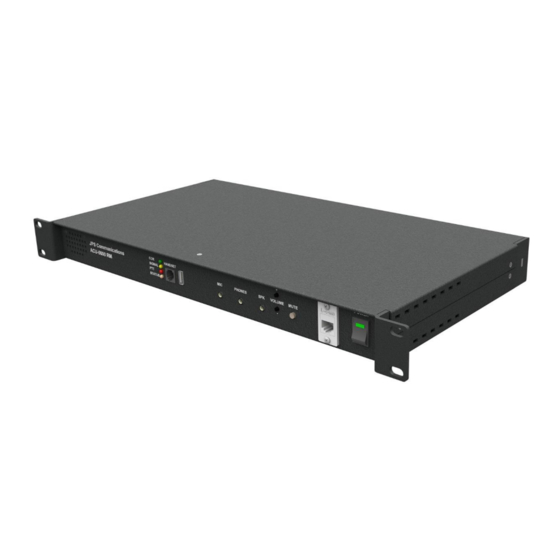
ACU-5000 Operations Manual ACU-5000 Rack Mount Version 3/4 View ACU-5000 Rack Mount Version Front View ACU-5000 Rack Mount Version Rear View Interoperability Now…
-
Page 21: Connectors, Controls, And Indicators
ACU-5000 Operations Manual 2.5 Connectors, Controls, and Indicators On the ACU-5000 front panel are the power on/off switch, a handset port, four indicator LEDs (Signal/COR/PTT/Status), a USB connector, a 3.5 mm external speaker connector and volume & mute controls. Also (on the rack mount version only) are 3.5 mm microphone and headphone jacks.
-
Page 22: Interoperability Now
ACU-5000 Operations Manual End of Section 2 Interoperability Now…
-
Page 23: Interface Capabilities
Radios are connected to the ACU-5000 via a cable that is likely to include interfacing circuitry (such as is used with JPS radio cables). Adapter cables (RJ-45 to D15) allow the use of the very large library of JPS radio cables already in existence, including standard Military 5 and 6 pin microphone connectors.
-
Page 24: Ip (Sip) Interface
There are two VoIP connections depicted in the diagram above. One connection is via an Analog Telephone Adapter to a PSTN port on the ACU-5000. Another connection is via SIP through an ACU-5000 VoIP channel. Both connections ultimately result in digital audio signals that are mixed internally in the ACU-5000.
-
Page 25
ACU-5000 Operations Manual The figure below shows four of the ACU-5000’s channels engaged in a conference call. Note that this system diagram could also be depicting a pair of two party connections. Note also that the laptop (shown in the figure as operating as a soft phone) could also be browsing to the IP address of the ACU-5000, so if the computer’s operator has the proper permissions, this operator… -
Page 26: Roip Interface
IP network. When the RoIP interface configuration is selected, an ACU-5000 channel can communicate with JPS ACU and NXU devices. The main use is to allow the ACU-5000 to interface a distant radio via an IP network (see Figure 3-4) below.
-
Page 27: Web-Based Configuration
Note: Due to ongoing upgrades and enhancements to the ACU-5000, the unit’s web pages may not be identical to those shown in this manual. Check Section 10 for upgrade information.
-
Page 28: Network Configuration
4.2.1 Network Configuration This page is used to set the ACU-5000’s IP address and other network settings. The page includes full instructions, and the default IP address can be seen in the screen shot below.
-
Page 29: Expanded System Configuration
ACU-5000 Operations Manual 4.2.2 Expanded System Configuration The ACU-5000 can be used as an individual 12 channel unit, or two units can be connected to create a 24 channel expanded system. The following rules apply to expanded systems: • The two ACU-5000 units may be connected together via a standard CAT5 cable plugged into one of the LAN ports on each of the units.
-
Page 30
If the expansion unit (that is, the other ACU-5000 that the one being configured will be connected to) is set to “Inactive” this means that, though configured for future use as an Expanded System, the chassis is currently functioning as a Stand Alone System. -
Page 31
ACU-5000 Operations Manual 4.2.3 User Management This page (available to the existing Super User and System Administrator roles) allows new users to be added to the system. Users are given one of the existing roles, with various permission sets (as noted on next manual page) associated with each role. Alternatively, new roles can be created or the permission sets of an existing role modified. -
Page 32: User Management
ACU-5000 Operations Manual Initial roles and associated permission sets: Super User (access to all system capabilities) o Control Nets o Change Channel Configurations o Change Basic System Settings o Apply/Update System Software o Configure Users and Roles o Create/Update Channel Profiles…
-
Page 33
ACU-5000 Operations Manual available to each authorized user. The PIN management tool and a full explanation are available from the ‘PIN Management’ option on the System menu. (Note that you must have user management permissions to create or modify PINs.) -
Page 34
ACU-5000 Operations Manual 4.2.5 Software Update The ACU-5000 may have software updates to add features or to fix errant behaviors. The Software Update tool provides a means for applying these updates. Use the ‘Upload New Software’ tool at the bottom of the page to upload a new software load to the system. After the software has been uploaded, it will be displayed in a chart with any other uploaded software releases. -
Page 35
ACU-5000 Operations Manual 4.2.6 License Update The ACU-5000’s channels are enabled via license keys. To increase the number of channels on the system, contact customer support. You may be asked to provide the current System ID (shown on the License Key Update tool; see below), and/or the existing license key file (available for download from the License Key Update tool). -
Page 36: Restore Defaults
ACU-5000 Operations Manual 4.2.7 Restore Defaults If necessary, the unit can be reset to its factory default settings. If Restore Default Users and Restore Default Network Settings are both set to No, the following are reset: • Channel configuration (type of channel & all settings) •…
-
Page 37: System Shutdown
Note that, if the system is shut down, the ACU-5000’s front panel power switch must be cycled to bring the unit back on. This is similar to shutting down any other computer; while it is shut down, there is no web interface and therefore no capability to respond to web commands.
-
Page 38
ACU-5000 Operations Manual End of Section 4 4-12 Interoperability Now… -
Page 39: Channel Configuration
Note: Due to ongoing upgrades and enhancements to the ACU-5000, the unit’s web pages may not be exactly the same as those shown in this manual. Check Section 10 for related information.
-
Page 40
ACU-5000 Operations Manual Interoperability Now… -
Page 41: Channel Configuration — Basic Settings
ACU-5000 Operations Manual 5.2 Channel Configuration – Basic Settings The first step is to select the desired channel type and other basic settings that apply to all channel types. These basic settings appear at the top of each settings page. Subsequent sections in this manual will provide details related to proper configuration of each channel type.
-
Page 42: Channel Configuration — Current Status
Save Configuration. The ACU-5000 front panel has a set of LEDs that may be useful in system set up & optimization. The COR, PTT, and Signal LEDs may be associated with any of the unit’s channels via the Show on Hardware LEDs selection.
-
Page 43: Channel Configuration — Handset
Channel “zero” can be configured only as the handset channel, and no other channel can have this configuration. The handset with PTT switch (provided in the ACU-5000 accessory kit) is plugged into the Handset connector on the unit’s front panel.
-
Page 44: Channel Configuration — Radio
Any of the channels one through 12 can be configured to the Radio channel type. The 12 RJ-45 connectors on the ACU-5000 rear panel provide the radio hardware interfaces. As can be seen on the associated configuration page, along with the Basic Settings and Current Channel Status settings, there are a variety of settings to optimize the interface.
-
Page 45: Channel Configuration — Pstn
System and the means of interfacing is to simply plug one end of a standard phone cord into one of the three ACU-5000 rear panel PSTN port, and the other into a wall outlet. Only channels 1 through 3 can be configured to the PSTN channel type.
-
Page 46
ACU-5000 Operations Manual Interoperability Now… -
Page 47: Channel Configuration — Sip
5.7 Channel Configuration — SIP Any of the ACU-5000’s channels 1 through twelve can be configured to the SIP channel type. The hardware interface for any and all of the SIP channels is any of the ACU-5000 RJ-45 LAN connectors.
-
Page 48: Channel Configuration — Roip
VoIP communications in a radio communications environment. The hardware interface for any and all of the RoIP channels is any of the ACU-5000 RJ-45 LAN connectors. See Section 3.4 for more information regarding the use of this RoIP protocol and the devices that employ it.
-
Page 49: Observe Mode
ACU-5000. To reach the Observe Mode, select it from the options presented after clicking on the “More Actions”…
-
Page 50
ACU-5000 Operations Manual This image shows the same system while in Observe Mode. End of Section 5 5-12 Interoperability Now… -
Page 51: System Preferences
ACU-5000 Operations Manual 6 System Preferences This section explains optional behaviors that can be selected via the Preferences pull down menu. Some preferences are stored on a per-user basis (e.g control preferences & password), while others apply to the system as a whole (such as system preferences and speed dials).
-
Page 52: Control Preferences
ACU-5000 system. Note: The ACU-5000 is optimized to allow quickest possible operation of the system. Sometimes it may be desirable that some operations are more difficult to perform; in particular, those that if not done correctly can cause an inexperienced operator to make disruptive changes to ongoing communications.
-
Page 53: Net Control — Standard Behavior Preferences
ACU-5000 Operations Manual take these factors into account. The Confirm and Deselect functions, for example, slow down operation, but with an aim towards ensuring proper system control. 6.2.1 Net Control — Standard Behavior Preferences Confirm on Selected Net Move If ‘yes’, the user must ‘commit’ channel moves by clicking on a net — channels will not be moved to a new net until this is completed (unconfirmed channel moves are represented by gray channel icons where the channel used to be).
-
Page 54: Net Control — Multi-Channel Click Behaviors
ACU-5000 Operations Manual Deselect Net Button (after action) If ‘yes’, when performing net-based operations (combining/separating/disbanding nets), the selected net control button is automatically de-selected. (Net Groups are often comprised of just 2 nets, so enabling this can save a click. However, this will require extra clicks when additional net operations are needed.)
-
Page 55: Preferences — Change Password
SIP User (see Section 9.3 regarding operation by remote DTMF). If the ACU-5000 is set to retain the Dial Out Destinations, appropriate numbers will be accessible when the operator of the Net Control GUI initiates a connection. By “appropriate” that means that, when the operator initiates a phone call, phone numbers will be accessible, not IP addresses.
-
Page 56: Preferences — System Dtmf Settings
The other relates to PIN Security requirements for users externally accessing the ACU-5000 — for example, telephone or SIP Phone users who dial in to the system and want to make connections to other channels User (see Section 9.3 regarding operation by remote DTMF).
-
Page 57: Preferences — Speed Dials
SIP channels, and a set for RoIP channels. Speed dials apply to all channels of a given type, not to individual channels. For example, if an ACU-5000 has both Channel 1 and Channel 2 set up as PSTN channels, a remote radio user calling in on Channel 6 would use the same PSTN…
-
Page 58: Preferences — Manage Channel Profiles
ACU-5000 Operations Manual 6.7 Preferences – Manage Channel Profiles Channel profiles are a means of saving different sets of settings for channels ahead of time. These settings can then be applied to the channel, preventing the need to manually configure them every time you change the channel type.
-
Page 59
ACU-5000 Operations Manual Alternatively, you may import profiles created by another ACU-5000 system – adding them to this system as if they were created locally. Conversely, profiles may be exported for use on other systems. After requesting a profile search a list of results will be displayed (see below) unless only one profile matched the search, in which case you will be taken directly to that profile’s configuration… -
Page 60
This sample profile shows multiple radios that use the same profile. Stored Application notes related to these radio models are stored within the ACU-5000 and can be retrieved by clicking on the “Download” button. A new search can also be requested from this page. -
Page 61
ACU-5000 Operations Manual Create Channel Profile page: Use this page to create a new profile from scratch. Interoperability Now 6-11… -
Page 62
ACU-5000 Operations Manual End of Section 6 6-12 Interoperability Now… -
Page 63: System Help
7 System Help 7.1 Help Types The ACU-5000 contains a wide array of Help features; most is context sensitive and can be reached without changing the current GUI page. For example, the channel configuration pages include context-sensitive help available by hovering over the adjacent circular blue question mark.
-
Page 64
ACU-5000 Operations Manual Furthermore, this Operations Manual, in PDF format, can be downloaded from the unit, again, click on the Help tag, and select “Documentation.” End of Section 7 Interoperability Now… -
Page 65: Control Capabilities
No special software or setup is required on this PC as control and configuration is performed via web pages served up by the ACU-5000. An operator will need to browse to the unit’s IP address and supply a proper User Name & Password.
-
Page 66: Ip Address And Password Reset
ACU-5000 Operations Manual 8.4 IP Address and Password Reset The system’s recessed reset switch provides a means to determine the unit’s current IP address and also to reset the unit to factory defaults. A momentary press of the switch (up to five seconds) results in the current IP address being read out over the handset and local speaker.
-
Page 67: Operating Instructions
9.1 Web-Based Operation- Net Management 9.1.1 Initial Net Control Page The figure below shows the Net Control GUI when none of the ACU-5000 channels are engaged in interoperability cross-patches. The channels are configured in the various types available; all channels are situated in the top «Free» net. Whenever any channel is in the Free net it is not communicating with any other channels (Monitor Mode operation and monitor communication excepted –…
-
Page 68
ACU-5000 Operations Manual buttons on the left; the net will darken to indicate that it is selected), and then click the channels. The channels may display a grayed-out box from the net they were in before being moved. This indicates that the channel move is not yet final, and serves as a temporary record of the channel’s previous net assignment. -
Page 69
ACU-5000 Operations Manual Note the information line at the bottom left of the screen shot. Various pertinent messages are placed here; each refers either to the current state (as with the “System Ready” message above) or the status of the previous operation. -
Page 70
ACU-5000 Operations Manual In the previous screen shot, the Net 3 icon and the net line are both still dark green to indicate that channel building operation is still active and other channels can be quickly added to the net. After clicking on radio channel number 5 (to add channel 5 to the net), and again on Net 3… -
Page 71
ACU-5000 Operations Manual Similarly, to hang up a channel (remove it from a net), click the ‘Disconnect’ button, then click the channel. Alternatively, simply “drag & drop” to the Free net. This will cause the channel to terminate its external link connection. If a channel is configured to ‘Disconnect on Free’, the channel will automatically hang up when it is moved to the Free net. -
Page 72
ACU-5000 Operations Manual When setup of this master is finished, click the ‘Monitor’ button again. The small status indicators in the upper left of the icons will disappear to indicate that the setup of this monitor group is complete. The screen shot on the following manual page shows what the system looks like after the setup is complete and terminated by clicking again on the Monitor button. -
Page 73
ACU-5000 Operations Manual There may be multiple master monitors, monitoring any or all of the channels simultaneously. Different master monitors and monitor groups are differentiated by the color-coded number icon on the channel in the lower corners of the icons. If multiple masters are monitoring a single channel, the icon will be a ‘+’ sign rather than a number. -
Page 74
ACU-5000 Operations Manual The following screen shot shows a Priority Connection in the process of being made between Channel 4 and Channel 7. When the building of this connection is complete (following another click on the Priority button), the yellow stars in the top left corners will no longer be present. -
Page 75
ACU-5000 Operations Manual To break a Priority Connection, select both ‘Remove’ and ‘Priority’ (yellow). Then click on any channel icon that’s currently in a Priority Connection to remove it from that connection. 9.1.7 Remove Button — Special Properties Use the ‘Remove’ button to break both Priority and Monitor Connections. If both types of connection in use simultaneously, the recommended operation is to select both ‘Remove”… -
Page 76
ACU-5000 Operations Manual Above – Before Net 3 and Net 6 are combined into a Net Group. Below – After the Net Group is built 9-10 Interoperability Now… -
Page 77
First identify the connection status that you want to be able to revert to later by simply clicking on “Mark Positions” (under “More Actions”). After this has been done, whenever “Revert” is selected, the ACU-5000 channel connection state will revert to the set of connections in existence when “Mark Positions” was selected. -
Page 78
ACU-5000 Operations Manual 9.1.10 Expanded System Operation Operation of an expanded system is no different than single-unit operation; there are simply more available channels and more potential nets. Below is the Channel Configuration Overview page. Note that: • For the Primary System, the handset is Channel 0 and the external interoperability channels are numbered one through twelve. -
Page 79
ACU-5000 Operations Manual The Net Control screen shot below shows an expanded system and the larger supply of nets to allow control of the additional channels. If the monitor is not ‘tall’ enough to show all the nets, the user may scroll down to see the higher number nets. -
Page 80
ACU-5000 Operations Manual 9.1.11 Live Status Information There is a variety of live, current status information available. Some is in the form of indicators that appear on the channel icons; additional information pertinent to any individual channel can be brought up by hovering over the channel icon. -
Page 81
ACU-5000 Operations Manual 9.1.12 Status Indicators on Channel Icons Note the small circle in the upper right corners of some of the channel icons in the previous image, with enlarged examples below. These small indicator icons provide additional information of a channel’s overall current state. -
Page 82
ACU-5000 Operations Manual 9.2 Modifying Connection Operations through Preferences Some of the Net Control operations can be modified through the Net Control Preferences page. The preferences can be tailored to individual users, and any user’s changes will not affect the operation seen by other users. -
Page 83
ACU-5000 Operations Manual 9.3 Operation Via Remote DTMF An ACU-5000 may be controlled via DTMF from the field. This may be from the DTMF keypads of radios or other 4-wire devices, remote telephones connected via PSTN, or VoIP phones or softphones. -
Page 84
For example, if the VHF radio user of the sample ACU-5000 system presses * * * the ACU-5000 will transmit a voice prompt over VHF identifying the channel number. -
Page 85
This section lists and explains updates and new features that have not yet been fully integrated into the text of this Operations Manual. These upgrades may result in differences in the current ACU-5000 web pages from what has provided in previous chapters. Additional improvements may have been made that are not included in this section. -
Page 86
ACU-5000 Operations Manual End of Document 10-2 Interoperability Now…
-
Contents
-
Table of Contents
-
Bookmarks
Quick Links
INTEROPERABILITY NOW
Installation and Operation Manual
ACU-5000
Twelve Channel
Interoperability
Gateway
JPS Interoperability Solutions
5800 Departure Drive
Raleigh, NC 27616
919-790-1011
Email:
sales@jpsinterop.com
/
support@jpsinterop.com
www.jpsinterop.com
JPS P/N 5100-100200
Revision 2.1
November 2017
Related Manuals for JPS ACU-5000
Summary of Contents for JPS ACU-5000
-
Page 1: Installation And Operation Manual
INTEROPERABILITY NOW Installation and Operation Manual ACU-5000 Twelve Channel Interoperability Gateway JPS Interoperability Solutions 5800 Departure Drive Raleigh, NC 27616 919-790-1011 Email: sales@jpsinterop.com support@jpsinterop.com www.jpsinterop.com JPS P/N 5100-100200 Revision 2.1 November 2017…
-
Page 2
PROPRIETARY STATEMENT The information contained in this manual is the property of JPS Interoperability Solutions and is intended for the purchaser’s use only. It may not be reproduced without the expressed written consent of JPS Interoperability Solutions, Inc. -
Page 3: Table Of Contents
ACU-5000 Operations Manual Table Of Contents 1 ACU-5000 OVERVIEW ……………………. 1-1 1.1 S ……………………….1-1 COPE 1.2 T ) ……..1-1 WELVE HANNEL NTEROPERABILITY APABILITY PLUS ANDSET 1.2.1 12 C OUR TO HANNELS CTIVATED 1.2.2 NTERFACE ONNECTORS 1.2.3 NTERCONNECT IMITATIONS 1.3 LAN P…
-
Page 4
ACU-5000 Operations Manual 4.2.1 ETWORK ONFIGURATION 4.2.2 XPANDED YSTEM ONFIGURATION 4.2.3 ANAGEMENT 4.2.4 PIN M ANAGEMENT 4.2.5 OFTWARE PDATE 4.2.6 ICENSE PDATE 4.2.7 4-10 ESTORE EFAULTS 4.2.8 4-11 YSTEM HUTDOWN 5 CHANNEL CONFIGURATION ………………..5-1 5.1 C ………………5-1 HANNEL… -
Page 5
DTMF – B 9.3.2 9-18 EMOTE REAK A ONNECTION DTMF – A 9.3.3 9-18 EMOTE TTENTION OMMAND DTMF – M 9.3.4 9-18 EMOTE ONITOR UNCTION 10 RECENT UPGRADES TO THE ACU-5000 …………….10-1 10.1 N ………………….. 10-1 PDATED EATURES Interoperability Now… -
Page 6
NXU-2A Network Extension Unit. A JPS device that interfaces a radio or other 4-wire device to other communications devices over an IP network. An NXU-2A uses RoIP. Private Branch Exchange. A telephone system that owned an operated by a private company (such as a manufacturing business) rather than by a telephone company such as ATT. -
Page 7
ACU-5000 Operations Manual Glossary Session Initiation Protocol – A flexible, standards-based, open protocol that initiates and manages communications between devices over an IP network. A computer that’s used as a VoIP phone. Soft Phone Squelch A means of detecting audio and causing some action when it is present, such as keying a transmitter or unmuting an audio path. -
Page 8
ACU-5000 Operations Manual blank page Interoperability Now… -
Page 9: Acu-5000 Overview
ACU-1000 or ACU-2000, where there is an ability of any channel to connect to any (or all) of the other modules in the ACU Chassis. The ACU-5000 is more capable and flexible — rather than relying on plug-in modules, the channels are themselves configurable to allow a wide range of devices to be interfaced.
-
Page 10: Interface Connectors
PSTN ports is 3. Configuration is done by web browser; no local/manual intervention is needed (that is, it’s not necessary to be at the same location as the ACU-5000 to configure a channel). Examples of possible configurations include any or all of the following (and many more):…
-
Page 11: Handset
RJ-12 connector. This is the same handset that is provided with other ACU devices. The handset interface has two main purposes: o Provide a simple means to properly set up & optimize an ACU-5000 interoperability system. The “level reference” provided by the handset port assists this operation.
-
Page 12: Control Methodology
NIST standard BSI interface protocol (Bridging Systems Interface). Links can be made to any other BSI compliant gateways (for example an ACU-2000 or another ACU-5000). The ACU-5000 currently supports inclusion in an ACU-1000/ACU-2000 based WAIS (Wide Area Interoperability System), however there are no provisions to dispatch to radios interfaced to the ACU-5000 (a feature of WAIS Enhanced and WAIS Enterprise).
-
Page 13: Specifications
ACU-5000 Operations Manual 1.13 Specifications Table 1-1 ACU-5000 Specifications Radio RX Audio Input Input Impedance Balanced 2.2k ohms, transformer coupled Incoming signals adjustable in approx 4 dB steps from –26 to +12 dBm to set 0 Input Level dBm nominal input; +15 dBm clipping…
-
Page 14: Equipment And Accessories Supplied
Note: When ordering a unit from the factory, use the 5100-1000xx number. This calls for the ACU-5000 tabletop unit, plus the accessory kit which has the power supply, handset, and the cables associated with each. To order that additional channels be added to an already purchased unit, use the 5100-112000 part number.
-
Page 15
Note: When ordering a unit from the factory, use the 5110-8000xx number. This calls for the ACU-5000 rack mount unit, plus the accessory kit which has the power supply, handset, and the cables associated with each. To order that additional channels be added to an already purchased unit, use the 5100-112000 part number. -
Page 16: Optional Equipment : Not Supplied
ACU Generic Radio Interface Cable; unterminated at radio end, D15 at other; 5961-291115- specify length: 15, 30, or 50 feet 15/30/50 Interface cables for a very wide range of commercial radios are available for purchase. Consult the JPS website or contact JPS Customer Service. Email: sales@jpsinterop.com support@jpsinterop.com…
-
Page 17: Installation
If it is necessary to return the equipment to the manufacturer, a Returned Material Authorization (RMA) number must first be obtained from JPS. This number must be noted on the outside of the packing carton and on all accompanying documents. When packing the unit for reshipment, it is best to use the original packaging for the unit;…
-
Page 18: Installation Considerations
ACU-5000 Operations Manual 2.2 Installation Considerations The ACU-5000 must be installed in a location that provides both protection from the weather and assurance of ambient temperatures between 0 and +40 degrees C. The unit is neither splash proof nor corrosion resistant and must be protected from exposure to salt spray. When the unit is mounted in a cabinet with other heat-generating equipment, the use of a rack blower is suggested to keep the cabinet interior temperature rise to a minimum.
-
Page 19: Interoperability Now
ACU-5000 Operations Manual ACU-5000 Tabletop Version Front View ACU-5000 Tabletop Version Rear View Interoperability Now…
-
Page 20: Interoperability Now
ACU-5000 Operations Manual ACU-5000 Rack Mount Version 3/4 View ACU-5000 Rack Mount Version Front View ACU-5000 Rack Mount Version Rear View Interoperability Now…
-
Page 21: Connectors, Controls, And Indicators
ACU-5000 Operations Manual 2.5 Connectors, Controls, and Indicators On the ACU-5000 front panel are the power on/off switch, a handset port, four indicator LEDs (Signal/COR/PTT/Status), a USB connector, a 3.5 mm external speaker connector and volume & mute controls. Also (on the rack mount version only) are 3.5 mm microphone and headphone jacks.
-
Page 22: Interoperability Now
ACU-5000 Operations Manual End of Section 2 Interoperability Now…
-
Page 23: Interface Capabilities
Radios are connected to the ACU-5000 via a cable that is likely to include interfacing circuitry (such as is used with JPS radio cables). Adapter cables (RJ-45 to D15) allow the use of the very large library of JPS radio cables already in existence, including standard Military 5 and 6 pin microphone connectors.
-
Page 24: Ip (Sip) Interface
There are two VoIP connections depicted in the diagram above. One connection is via an Analog Telephone Adapter to a PSTN port on the ACU-5000. Another connection is via SIP through an ACU-5000 VoIP channel. Both connections ultimately result in digital audio signals that are mixed internally in the ACU-5000.
-
Page 25
ACU-5000 Operations Manual The figure below shows four of the ACU-5000’s channels engaged in a conference call. Note that this system diagram could also be depicting a pair of two party connections. Note also that the laptop (shown in the figure as operating as a soft phone) could also be browsing to the IP address of the ACU-5000, so if the computer’s operator has the proper permissions, this operator… -
Page 26: Roip Interface
IP network. When the RoIP interface configuration is selected, an ACU-5000 channel can communicate with JPS ACU and NXU devices. The main use is to allow the ACU-5000 to interface a distant radio via an IP network (see Figure 3-4) below.
-
Page 27: Web-Based Configuration
Note: Due to ongoing upgrades and enhancements to the ACU-5000, the unit’s web pages may not be identical to those shown in this manual. Check Section 10 for upgrade information.
-
Page 28: Network Configuration
4.2.1 Network Configuration This page is used to set the ACU-5000’s IP address and other network settings. The page includes full instructions, and the default IP address can be seen in the screen shot below.
-
Page 29: Expanded System Configuration
ACU-5000 Operations Manual 4.2.2 Expanded System Configuration The ACU-5000 can be used as an individual 12 channel unit, or two units can be connected to create a 24 channel expanded system. The following rules apply to expanded systems: • The two ACU-5000 units may be connected together via a standard CAT5 cable plugged into one of the LAN ports on each of the units.
-
Page 30
If the expansion unit (that is, the other ACU-5000 that the one being configured will be connected to) is set to “Inactive” this means that, though configured for future use as an Expanded System, the chassis is currently functioning as a Stand Alone System. -
Page 31
ACU-5000 Operations Manual 4.2.3 User Management This page (available to the existing Super User and System Administrator roles) allows new users to be added to the system. Users are given one of the existing roles, with various permission sets (as noted on next manual page) associated with each role. Alternatively, new roles can be created or the permission sets of an existing role modified. -
Page 32: User Management
ACU-5000 Operations Manual Initial roles and associated permission sets: Super User (access to all system capabilities) o Control Nets o Change Channel Configurations o Change Basic System Settings o Apply/Update System Software o Configure Users and Roles o Create/Update Channel Profiles…
-
Page 33
ACU-5000 Operations Manual available to each authorized user. The PIN management tool and a full explanation are available from the ‘PIN Management’ option on the System menu. (Note that you must have user management permissions to create or modify PINs.) -
Page 34
ACU-5000 Operations Manual 4.2.5 Software Update The ACU-5000 may have software updates to add features or to fix errant behaviors. The Software Update tool provides a means for applying these updates. Use the ‘Upload New Software’ tool at the bottom of the page to upload a new software load to the system. After the software has been uploaded, it will be displayed in a chart with any other uploaded software releases. -
Page 35
ACU-5000 Operations Manual 4.2.6 License Update The ACU-5000’s channels are enabled via license keys. To increase the number of channels on the system, contact customer support. You may be asked to provide the current System ID (shown on the License Key Update tool; see below), and/or the existing license key file (available for download from the License Key Update tool). -
Page 36: Restore Defaults
ACU-5000 Operations Manual 4.2.7 Restore Defaults If necessary, the unit can be reset to its factory default settings. If Restore Default Users and Restore Default Network Settings are both set to No, the following are reset: • Channel configuration (type of channel & all settings) •…
-
Page 37: System Shutdown
Note that, if the system is shut down, the ACU-5000’s front panel power switch must be cycled to bring the unit back on. This is similar to shutting down any other computer; while it is shut down, there is no web interface and therefore no capability to respond to web commands.
-
Page 38
ACU-5000 Operations Manual End of Section 4 4-12 Interoperability Now… -
Page 39: Channel Configuration
Note: Due to ongoing upgrades and enhancements to the ACU-5000, the unit’s web pages may not be exactly the same as those shown in this manual. Check Section 10 for related information.
-
Page 40
ACU-5000 Operations Manual Interoperability Now… -
Page 41: Channel Configuration — Basic Settings
ACU-5000 Operations Manual 5.2 Channel Configuration – Basic Settings The first step is to select the desired channel type and other basic settings that apply to all channel types. These basic settings appear at the top of each settings page. Subsequent sections in this manual will provide details related to proper configuration of each channel type.
-
Page 42: Channel Configuration — Current Status
Save Configuration. The ACU-5000 front panel has a set of LEDs that may be useful in system set up & optimization. The COR, PTT, and Signal LEDs may be associated with any of the unit’s channels via the Show on Hardware LEDs selection.
-
Page 43: Channel Configuration — Handset
Channel “zero” can be configured only as the handset channel, and no other channel can have this configuration. The handset with PTT switch (provided in the ACU-5000 accessory kit) is plugged into the Handset connector on the unit’s front panel.
-
Page 44: Channel Configuration — Radio
Any of the channels one through 12 can be configured to the Radio channel type. The 12 RJ-45 connectors on the ACU-5000 rear panel provide the radio hardware interfaces. As can be seen on the associated configuration page, along with the Basic Settings and Current Channel Status settings, there are a variety of settings to optimize the interface.
-
Page 45: Channel Configuration — Pstn
System and the means of interfacing is to simply plug one end of a standard phone cord into one of the three ACU-5000 rear panel PSTN port, and the other into a wall outlet. Only channels 1 through 3 can be configured to the PSTN channel type.
-
Page 46
ACU-5000 Operations Manual Interoperability Now… -
Page 47: Channel Configuration — Sip
5.7 Channel Configuration — SIP Any of the ACU-5000’s channels 1 through twelve can be configured to the SIP channel type. The hardware interface for any and all of the SIP channels is any of the ACU-5000 RJ-45 LAN connectors.
-
Page 48: Channel Configuration — Roip
VoIP communications in a radio communications environment. The hardware interface for any and all of the RoIP channels is any of the ACU-5000 RJ-45 LAN connectors. See Section 3.4 for more information regarding the use of this RoIP protocol and the devices that employ it.
-
Page 49: Observe Mode
ACU-5000. To reach the Observe Mode, select it from the options presented after clicking on the “More Actions”…
-
Page 50
ACU-5000 Operations Manual This image shows the same system while in Observe Mode. End of Section 5 5-12 Interoperability Now… -
Page 51: System Preferences
ACU-5000 Operations Manual 6 System Preferences This section explains optional behaviors that can be selected via the Preferences pull down menu. Some preferences are stored on a per-user basis (e.g control preferences & password), while others apply to the system as a whole (such as system preferences and speed dials).
-
Page 52: Control Preferences
ACU-5000 system. Note: The ACU-5000 is optimized to allow quickest possible operation of the system. Sometimes it may be desirable that some operations are more difficult to perform; in particular, those that if not done correctly can cause an inexperienced operator to make disruptive changes to ongoing communications.
-
Page 53: Net Control — Standard Behavior Preferences
ACU-5000 Operations Manual take these factors into account. The Confirm and Deselect functions, for example, slow down operation, but with an aim towards ensuring proper system control. 6.2.1 Net Control — Standard Behavior Preferences Confirm on Selected Net Move If ‘yes’, the user must ‘commit’ channel moves by clicking on a net — channels will not be moved to a new net until this is completed (unconfirmed channel moves are represented by gray channel icons where the channel used to be).
-
Page 54: Net Control — Multi-Channel Click Behaviors
ACU-5000 Operations Manual Deselect Net Button (after action) If ‘yes’, when performing net-based operations (combining/separating/disbanding nets), the selected net control button is automatically de-selected. (Net Groups are often comprised of just 2 nets, so enabling this can save a click. However, this will require extra clicks when additional net operations are needed.)
-
Page 55: Preferences — Change Password
SIP User (see Section 9.3 regarding operation by remote DTMF). If the ACU-5000 is set to retain the Dial Out Destinations, appropriate numbers will be accessible when the operator of the Net Control GUI initiates a connection. By “appropriate” that means that, when the operator initiates a phone call, phone numbers will be accessible, not IP addresses.
-
Page 56: Preferences — System Dtmf Settings
The other relates to PIN Security requirements for users externally accessing the ACU-5000 — for example, telephone or SIP Phone users who dial in to the system and want to make connections to other channels User (see Section 9.3 regarding operation by remote DTMF).
-
Page 57: Preferences — Speed Dials
SIP channels, and a set for RoIP channels. Speed dials apply to all channels of a given type, not to individual channels. For example, if an ACU-5000 has both Channel 1 and Channel 2 set up as PSTN channels, a remote radio user calling in on Channel 6 would use the same PSTN…
-
Page 58: Preferences — Manage Channel Profiles
ACU-5000 Operations Manual 6.7 Preferences – Manage Channel Profiles Channel profiles are a means of saving different sets of settings for channels ahead of time. These settings can then be applied to the channel, preventing the need to manually configure them every time you change the channel type.
-
Page 59
ACU-5000 Operations Manual Alternatively, you may import profiles created by another ACU-5000 system – adding them to this system as if they were created locally. Conversely, profiles may be exported for use on other systems. After requesting a profile search a list of results will be displayed (see below) unless only one profile matched the search, in which case you will be taken directly to that profile’s configuration… -
Page 60
This sample profile shows multiple radios that use the same profile. Stored Application notes related to these radio models are stored within the ACU-5000 and can be retrieved by clicking on the “Download” button. A new search can also be requested from this page. -
Page 61
ACU-5000 Operations Manual Create Channel Profile page: Use this page to create a new profile from scratch. Interoperability Now 6-11… -
Page 62
ACU-5000 Operations Manual End of Section 6 6-12 Interoperability Now… -
Page 63: System Help
7 System Help 7.1 Help Types The ACU-5000 contains a wide array of Help features; most is context sensitive and can be reached without changing the current GUI page. For example, the channel configuration pages include context-sensitive help available by hovering over the adjacent circular blue question mark.
-
Page 64
ACU-5000 Operations Manual Furthermore, this Operations Manual, in PDF format, can be downloaded from the unit, again, click on the Help tag, and select “Documentation.” End of Section 7 Interoperability Now… -
Page 65: Control Capabilities
No special software or setup is required on this PC as control and configuration is performed via web pages served up by the ACU-5000. An operator will need to browse to the unit’s IP address and supply a proper User Name & Password.
-
Page 66: Ip Address And Password Reset
ACU-5000 Operations Manual 8.4 IP Address and Password Reset The system’s recessed reset switch provides a means to determine the unit’s current IP address and also to reset the unit to factory defaults. A momentary press of the switch (up to five seconds) results in the current IP address being read out over the handset and local speaker.
-
Page 67: Operating Instructions
9.1 Web-Based Operation- Net Management 9.1.1 Initial Net Control Page The figure below shows the Net Control GUI when none of the ACU-5000 channels are engaged in interoperability cross-patches. The channels are configured in the various types available; all channels are situated in the top «Free» net. Whenever any channel is in the Free net it is not communicating with any other channels (Monitor Mode operation and monitor communication excepted –…
-
Page 68
ACU-5000 Operations Manual buttons on the left; the net will darken to indicate that it is selected), and then click the channels. The channels may display a grayed-out box from the net they were in before being moved. This indicates that the channel move is not yet final, and serves as a temporary record of the channel’s previous net assignment. -
Page 69
ACU-5000 Operations Manual Note the information line at the bottom left of the screen shot. Various pertinent messages are placed here; each refers either to the current state (as with the “System Ready” message above) or the status of the previous operation. -
Page 70
ACU-5000 Operations Manual In the previous screen shot, the Net 3 icon and the net line are both still dark green to indicate that channel building operation is still active and other channels can be quickly added to the net. After clicking on radio channel number 5 (to add channel 5 to the net), and again on Net 3… -
Page 71
ACU-5000 Operations Manual Similarly, to hang up a channel (remove it from a net), click the ‘Disconnect’ button, then click the channel. Alternatively, simply “drag & drop” to the Free net. This will cause the channel to terminate its external link connection. If a channel is configured to ‘Disconnect on Free’, the channel will automatically hang up when it is moved to the Free net. -
Page 72
ACU-5000 Operations Manual When setup of this master is finished, click the ‘Monitor’ button again. The small status indicators in the upper left of the icons will disappear to indicate that the setup of this monitor group is complete. The screen shot on the following manual page shows what the system looks like after the setup is complete and terminated by clicking again on the Monitor button. -
Page 73
ACU-5000 Operations Manual There may be multiple master monitors, monitoring any or all of the channels simultaneously. Different master monitors and monitor groups are differentiated by the color-coded number icon on the channel in the lower corners of the icons. If multiple masters are monitoring a single channel, the icon will be a ‘+’ sign rather than a number. -
Page 74
ACU-5000 Operations Manual The following screen shot shows a Priority Connection in the process of being made between Channel 4 and Channel 7. When the building of this connection is complete (following another click on the Priority button), the yellow stars in the top left corners will no longer be present. -
Page 75
ACU-5000 Operations Manual To break a Priority Connection, select both ‘Remove’ and ‘Priority’ (yellow). Then click on any channel icon that’s currently in a Priority Connection to remove it from that connection. 9.1.7 Remove Button — Special Properties Use the ‘Remove’ button to break both Priority and Monitor Connections. If both types of connection in use simultaneously, the recommended operation is to select both ‘Remove”… -
Page 76
ACU-5000 Operations Manual Above – Before Net 3 and Net 6 are combined into a Net Group. Below – After the Net Group is built 9-10 Interoperability Now… -
Page 77
First identify the connection status that you want to be able to revert to later by simply clicking on “Mark Positions” (under “More Actions”). After this has been done, whenever “Revert” is selected, the ACU-5000 channel connection state will revert to the set of connections in existence when “Mark Positions” was selected. -
Page 78
ACU-5000 Operations Manual 9.1.10 Expanded System Operation Operation of an expanded system is no different than single-unit operation; there are simply more available channels and more potential nets. Below is the Channel Configuration Overview page. Note that: • For the Primary System, the handset is Channel 0 and the external interoperability channels are numbered one through twelve. -
Page 79
ACU-5000 Operations Manual The Net Control screen shot below shows an expanded system and the larger supply of nets to allow control of the additional channels. If the monitor is not ‘tall’ enough to show all the nets, the user may scroll down to see the higher number nets. -
Page 80
ACU-5000 Operations Manual 9.1.11 Live Status Information There is a variety of live, current status information available. Some is in the form of indicators that appear on the channel icons; additional information pertinent to any individual channel can be brought up by hovering over the channel icon. -
Page 81
ACU-5000 Operations Manual 9.1.12 Status Indicators on Channel Icons Note the small circle in the upper right corners of some of the channel icons in the previous image, with enlarged examples below. These small indicator icons provide additional information of a channel’s overall current state. -
Page 82
ACU-5000 Operations Manual 9.2 Modifying Connection Operations through Preferences Some of the Net Control operations can be modified through the Net Control Preferences page. The preferences can be tailored to individual users, and any user’s changes will not affect the operation seen by other users. -
Page 83
ACU-5000 Operations Manual 9.3 Operation Via Remote DTMF An ACU-5000 may be controlled via DTMF from the field. This may be from the DTMF keypads of radios or other 4-wire devices, remote telephones connected via PSTN, or VoIP phones or softphones. -
Page 84
For example, if the VHF radio user of the sample ACU-5000 system presses * * * the ACU-5000 will transmit a voice prompt over VHF identifying the channel number. -
Page 85
This section lists and explains updates and new features that have not yet been fully integrated into the text of this Operations Manual. These upgrades may result in differences in the current ACU-5000 web pages from what has provided in previous chapters. Additional improvements may have been made that are not included in this section. -
Page 86
ACU-5000 Operations Manual End of Document 10-2 Interoperability Now…
(Ocr-Read Summary of Contents of some pages of the JPS ACU-5000 Document (Main Content), UPD: 19 June 2023)
-
1, JPS ACU-5000 INTEROPERABILITY NOW Installation and Operation Manual ACU-5000 Twelve Channel Interoperability Gateway JPS Interoperability Solutions 5800 Departure Drive Raleigh, NC 27616 919-790-1011 Email: [email protected] / [email protected] www.jpsinterop.com JPS P/N 5100-100200 Revision 2.1 November 2017 …
-
3, ACU-5000 Operations Manual Interoperability Now 3 Table Of Contents 1 ACU-5000 OVERVIEW ………………………………………………………………………………………………….. 1-1 1.1 SCOPE ………………………………………………………………………………………………………………………….. 1-1 1.2 TWELVE CHANNEL INTEROPERABILITY CAPABILITY (PLUS HANDSET) ……………….…
-
15, ACU-5000 Operations Manual Interoperability Now 1-7 Table 1-3 Equipment and Accessories Supplied Rack Mount Version ACU-5000 Shipping Level — P/N 5110-800000 (4 channel) to 5110-800012 (12 channel) Quantity Item JPS P/N 1 ACU-5000 Final Assembly (main box only – rack mount 4 channels) 5110-800000 ACU-5000 Final Assembly (main box only – rack mount 5 channels) 5110-800005 ACU-5000 Final Assembly (main box only – rack mount 6…
-
27, ACU-5000 Operations Manual Interoperability Now 4-1 4 Web-Based Configuration The unit is configured via its web-based Graphical User Interface (GUI). The GUI is carefully designed to provide a range of easily accessible context-sensitive help information. Note: Due to ongoing upgrades and enhancements to the ACU-5000, the unit’s web pages may not be identical to those shown in this manual. Check Section 10 for upgrade information. …
-
42, ACU-5000 Operations Manual 5-4 Interoperability Now 5.3 Channel Configuration – Current Status Information related to each channel’s current status is available via this section in the top right of each channel configuration page alongside the Basic Settings. As with other configuration selections, context-sensitive help is available. The status information applies to the existing condition of the channel, irresp…
-
18, ACU-5000 Operations Manual 2-2 Interoperability Now 2.2 Installation Considerations The ACU-5000 must be installed in a location that provides both protection from the weather and assurance of ambient temperatures between 0 and +40 degrees C. The unit is neither splash proof nor corrosion resistant and must be protected from exposure to salt spray. When the unit is mounted in a cabinet with other heat-generating equipment, the use of a rack b…
-
85, JPS ACU-5000 ACU-5000 Operations Manual Interoperability Now 10-1 10 Recent Upgrades to the ACU-5000 This section lists and explains updates and new features that have not yet been fully integrated into the text of this Operations Manual. These upgrades may result in differences in the current ACU-5000 web pages from what has provided in previous chapters. Additional improvements may have been made that are not included in this section. 10.1 New/Updated Featur…
-
52, ACU-5000 Operations Manual 6-2 Interoperability Now 6.2 Control Preferences These preferences are open to all users and allow variations in how the Net Control GUI is viewed and operated. For example, some changes allow users who are more familiar with the ACU Controller to modify some GUI behaviors to more closely match that application. If the system is set to ‘Confirm,’ the user can to view the results …
-
12, ACU-5000 Operations Manual 1-4 Interoperability Now 1.8 Control Methodology The unit may be controlled (create and dissolve cross-connections between the devices interfaced to the unit) in two ways: o Via a web-based graphical user interface that allows users to create interoperability nets by simple mouse-click procedures. o Via user-initiated DTMF sequences. Section 6 provides details about both control methodologies. 1.9 Expansion Capability The commu…
-
59, ACU-5000 Operations Manual Interoperability Now 6-9 Alternatively, you may import profiles created by another ACU-5000 system – adding them to this system as if they were created locally. Conversely, profiles may be exported for use on other systems. After requesting a profile search a list of results will be displayed (see below) unless only one profile matched the search, in which case you wi…
-
49, ACU-5000 Operations Manual Interoperability Now 5-11 5.9 Observe Mode The Observe Mode assists system setup and optimization. It allows near instantaneous indications of COR, PTT, and Signal status in the web browser. Due to the IP nature of the system and the many processes underway and the associated communications between system components, there is some delay during normal (non Observe …
-
79, JPS ACU-5000 ACU-5000 Operations Manual Interoperability Now 9-13 The Net Control screen shot below shows an expanded system and the larger supply of nets to allow control of the additional channels. If the monitor is not ‘tall’ enough to show all the nets, the user may scroll down to see the higher number nets.
… -
43, ACU-5000 Operations Manual Interoperability Now 5-5 5.4 Channel Configuration — Handset Channel “zero” can be configured only as the handset channel, and no other channel can have this configuration. The handset with PTT switch (provided in the ACU-5000 accessory kit) is plugged into the Handset connector on the unit’s front panel. Note that the handset earpiece and the speaker are run by th…
-
13, ACU-5000 Operations Manual Interoperability Now 1-5 1.13 Specifications Table 1-1 ACU-5000 Specifications Radio RX Audio Input Input Impedance Balanced 2.2k ohms, transformer coupled Input Level Incoming signals adjustable in approx 4 dB steps from –26 to +12 dBm to set 0 dBm nominal input; +15 dBm clipping Radio TX Audio Output Output Impedance Unbalanced 600 ohms, AC Coupled Output Level Adjustable from –26 to +12 dBm in approx 4 d…
-
55, ACU-5000 Operations Manual Interoperability Now 6-5 6.3 Preferences – Change Password All users have the capability of changing their own passwords. This is operation is performed in the typical fashion as shown below. 6.4 Preferences – System Memory Settings The System Memory Settings preferences set what the ACU-5000 will retain under various conditions. If ‘Resto…
-
71, ACU-5000 Operations Manual Interoperability Now 9-5 Similarly, to hang up a channel (remove it from a net), click the ‘Disconnect’ button, then click the channel. Alternatively, simply “drag & drop” to the Free net. This will cause the channel to terminate its external link connection. If a channel is configured to ‘Disconnect on Free’, the channel will automatically hang up when it is moved to the Free net. 9.1.4 Dial In Operation (answer …
-
50, ACU-5000 Operations Manual 5-12 Interoperability Now This image shows the same system while in Observe Mode. End of Section 5
…
Table of Contents for JPS ACU-5000:
-
ACU-5000 Operations Manual 4 Interoperability Now 4.2.1 NETWORK CONFIGURATION 4-2 4.2.2 EXPANDED SYSTEM CONFIGURATION 4-3 4.2.3 USER MANAGEMENT 4-5 4.2.4 PIN MANAGEMENT 4-6 4.2.5 SOFTWARE UPDATE 4-8 4.2.6 LICENSE UPDATE 4-9 4.2.7 RESTORE DEFAULTS 4-10 4.2.8 SYSTEM SHUTDOWN 4-11 5 CHANNEL CONFIGURATION ………………………………………………………………………………
-
ACU-5000 Operations Manual 1-8 Interoperability Now 1.15 Optional Equipment: Not Supplied Table 1-4 Optional Equipment — Not Supplied Description JPS P/N RJ-45 to D15 Adapter Cable; shielded CAT5 cable with Adapter-for use with ACU standard radio interface cables (1 foot long) 5100-110010 ACU Generic Radio Interface Cable; unterminated at radio end, D15 at other; specify length: 15, 30, or 50 feet 5961-291115- 15/30/50 Interface cables
-
ACU-5000 Operations Manual 5-2 Interoperability Now
-
ACU-5000 Operations Manual Interoperability Now 1-3 1.4 Handset A handset with PTT switch is provided with the unit, which can be plugged into the single front panel RJ-12 connector. This is the same handset that is provided with other ACU devices. The handset interface has two main purposes: o Provide a simple means to properly set up & optimize an ACU-5000 interoperability system. The “level reference” provided by the handset port assists this operation. o Allow a local operator t
-
ACU-5000 Operations Manual 4-6 Interoperability Now Initial roles and associated permission sets: Super User (access to all system capabilities) o Control Nets o Change Channel Configurations o Change Basic System Settings o Apply/Update System Software o Configure Users and Roles o Create/Update Channel Profiles System Admin o Control Nets o Change Channel Configurations o Change Basic Syst
-
ACU-5000 Operations Manual 1-6 Interoperability Now 1.14 Equipment and Accessories Supplied Table 1-2 Equipment and Accessories Supplied — Tabletop Version ACU-5000 Shipping Level — P/N 5100-100000 (4 channel) to 5100-100012 (12 channel) Quantity Item JPS P/N 1 ACU-5000 Final Assembly (main box only – tabletop 4 channels) 5100-100000 ACU-5000 Final Assembly (main box only – tabletop 5 channels
-
ACU-5000 Operations Manual 1-4 Interoperability Now 1.8 Control Methodology The unit may be controlled (create and dissolve cross-connections between the devices interfaced to the unit) in two ways: o Via a web-based graphical user interface that allows users to create interoperability nets by simple mouse-click procedures. o Via user-initiated DTMF sequences. Section 6 provides details a
-
ACU-5000 Operations Manual Interoperability Now 10-1 10 Recent Upgrades to the ACU-5000 This section lists and explains updates and new features that have not yet been fully integrated into the text of this Operations Manual. These upgrades may result in differences in the current ACU-5000 web pages from what has provided in previous chapters. Additional improvements may have been made that are not included in this section. 10.1 New/Updated Features
-
ACU-5000 Operations Manual Interoperability Now 1-7 Table 1-3 Equipment and Accessories Supplied Rack Mount Version ACU-5000 Shipping Level — P/N 5110-800000 (4 channel) to 5110-800012 (12 channel) Quantity Item JPS P/N 1 ACU-5000 Final Assembly (main box only – rack mount 4 channels) 5110-800000 ACU-5000 Final Assembly (main box only – rack mount 5 channels) 5110-800005 ACU-5000 Final Assembly (main box only – rack mount 6 channels) 5110-80
-
ACU-5000 Operations Manual Interoperability Now 1-5 1.13 Specifications Table 1-1 ACU-5000 Specifications Radio RX Audio Input Input Impedance Balanced 2.2k ohms, transformer coupled Input Level Incoming signals adjustable in approx 4 dB steps from –26 to +12 dBm to set 0 dBm nominal input; +15 dBm clipping Radio TX Audio Output Output Impedance Unbalanced 600 ohms, AC Coupled Output Level Adjustable from –26 to +12 dBm in approx
-
ACU-5000 Operations Manual Interoperability Now 4-7 available to each authorized user. The PIN management tool and a full explanation are available from the ‘PIN Management’ option on the System menu. (Note that you must have user management permissions to create or modify PINs.)
-
ACU-5000 Operations Manual 6-2 Interoperability Now 6.2 Control Preferences These preferences are open to all users and allow variations in how the Net Control GUI is viewed and operated. For example, some changes allow users who are more familiar with the ACU Controller to modify some GUI behaviors to more closely match that application. If the system is set to ‘Confirm,’ the user can to view the results of net building or disbanding operations before they actually take place, and allows the opportunity to u
-
ACU-5000 Operations Manual 4-2 Interoperability Now The System tab provides the capability to view or change a variety of system configuration settings as shown in the screen shot below. This overview can be reached by clicking on the System tab; the various configuration settings pages can be reached by selection from the drop- down menu or by clicking on the appropriate hypertext in the overview screen. 4.2.1 Network
-
ACU-5000 Operations Manual Interoperability Now 9-3 Note the information line at the bottom left of the screen shot. Various pertinent messages are placed here; each refers either to the current state (as with the “System Ready” message above) or the status of the previous operation. Note: “Drag-and-Drop” procedures can also be used to create and disband nets. Simply drag an icon to a net line to plac
Questions, Opinions and Exploitation Impressions:
You can ask a question, express your opinion or share our experience of JPS ACU-5000 device using right now.
- Home
- Brands
- JPS Manuals
- Gateway
- JPS ACU-5000
1 docs – User Manuals, Help Guides and Specs – for the JPS ACU-5000 product are present in our data base.
|
|
Product Types:
|
")
Tips for Finding Manuals:
This web-page provides a list of 1 accessible operating manuals and information books describing JPS ACU-5000.
All manuals and instructions for JPS ACU-5000 are introduced in an easy-to-use PDF format and may be gratuitously downloaded or looked through directly from the site.
The page offers the following types of manuals: Gateway.
Helpful hints: While selecting a necessary guide for JPS ACU-5000 one should pay special attention to the type of the document.
We try to supply you with the fullest possible set of papers we or our users are able to find. These may be overviews and specifications of the device, mounting and installing instructions, the unit operating rules and maintenance regulations and much more.
Haven’t found a required manual for your JPS ACU-5000?
Check in a while. We update our guides collection and add new documents on a daily basis for you to be always able to find the very paper you need on our web-site. In case you own a directory or an instruction for JPS ACU-5000, which is absent on our site, and you’d like to share it with the public, please send it to us as a scanned copy or a PDF file, and we’ll definitely place it on our page while providing your name as a supplier of the doc. Lots of our users will be grateful for your assistance!